EP2889183B1 - Vehicle rear view mirror assembly - Google Patents
Vehicle rear view mirror assembly Download PDFInfo
- Publication number
- EP2889183B1 EP2889183B1 EP14198076.3A EP14198076A EP2889183B1 EP 2889183 B1 EP2889183 B1 EP 2889183B1 EP 14198076 A EP14198076 A EP 14198076A EP 2889183 B1 EP2889183 B1 EP 2889183B1
- Authority
- EP
- European Patent Office
- Prior art keywords
- base
- rear view
- view mirror
- mirror assembly
- vehicle rear
- Prior art date
- Legal status (The legal status is an assumption and is not a legal conclusion. Google has not performed a legal analysis and makes no representation as to the accuracy of the status listed.)
- Active
Links
Images


Classifications
-
- B—PERFORMING OPERATIONS; TRANSPORTING
- B60—VEHICLES IN GENERAL
- B60R—VEHICLES, VEHICLE FITTINGS, OR VEHICLE PARTS, NOT OTHERWISE PROVIDED FOR
- B60R1/00—Optical viewing arrangements; Real-time viewing arrangements for drivers or passengers using optical image capturing systems, e.g. cameras or video systems specially adapted for use in or on vehicles
- B60R1/02—Rear-view mirror arrangements
- B60R1/06—Rear-view mirror arrangements mounted on vehicle exterior
-
- B—PERFORMING OPERATIONS; TRANSPORTING
- B60—VEHICLES IN GENERAL
- B60R—VEHICLES, VEHICLE FITTINGS, OR VEHICLE PARTS, NOT OTHERWISE PROVIDED FOR
- B60R1/00—Optical viewing arrangements; Real-time viewing arrangements for drivers or passengers using optical image capturing systems, e.g. cameras or video systems specially adapted for use in or on vehicles
- B60R1/02—Rear-view mirror arrangements
- B60R1/08—Rear-view mirror arrangements involving special optical features, e.g. avoiding blind spots, e.g. convex mirrors; Side-by-side associations of rear-view and other mirrors
- B60R1/081—Rear-view mirror arrangements involving special optical features, e.g. avoiding blind spots, e.g. convex mirrors; Side-by-side associations of rear-view and other mirrors avoiding blind spots, e.g. by using a side-by-side association of mirrors
-
- B—PERFORMING OPERATIONS; TRANSPORTING
- B62—LAND VEHICLES FOR TRAVELLING OTHERWISE THAN ON RAILS
- B62D—MOTOR VEHICLES; TRAILERS
- B62D65/00—Designing, manufacturing, e.g. assembling, facilitating disassembly, or structurally modifying motor vehicles or trailers, not otherwise provided for
- B62D65/02—Joining sub-units or components to, or positioning sub-units or components with respect to, body shell or other sub-units or components
- B62D65/024—Positioning of sub-units or components with respect to body shell or other sub-units or components
-
- B—PERFORMING OPERATIONS; TRANSPORTING
- B62—LAND VEHICLES FOR TRAVELLING OTHERWISE THAN ON RAILS
- B62D—MOTOR VEHICLES; TRAILERS
- B62D65/00—Designing, manufacturing, e.g. assembling, facilitating disassembly, or structurally modifying motor vehicles or trailers, not otherwise provided for
- B62D65/02—Joining sub-units or components to, or positioning sub-units or components with respect to, body shell or other sub-units or components
- B62D65/16—Joining sub-units or components to, or positioning sub-units or components with respect to, body shell or other sub-units or components the sub-units or components being exterior fittings, e.g. bumpers, lights, wipers, exhausts
-
- G—PHYSICS
- G02—OPTICS
- G02B—OPTICAL ELEMENTS, SYSTEMS OR APPARATUS
- G02B5/00—Optical elements other than lenses
- G02B5/08—Mirrors
Definitions
- the present invention relates to a vehicle rear view mirror assembly in which an auxiliary lens is further rotated to adjust an angle between the auxiliary lens and a main lens, after the main lens is adjusted toward a desired position by a driver, thus increasing a visible range.
- a conventional rear view mirror is mounted on a front end of a vehicle so that a driver learns driving states while driving a car.
- some blind spots cannot be seen clearly because of a limited visible range of the conventional rear view mirror.
- the present invention has arisen to mitigate and/or obviate the afore-described disadvantages.
- a rear view mirror assembly comprising a base and three angle adjustable lenses connected to the base via ball and socket joints allowing to adjust the angles between the base and the mirror plane of each lens individually.
- a rear view mirror assembly comprising a base and an angle adjustable lens connected to the base via a positioning portion formed on the base and a connecting portion formed on the lens.
- US 4 714 322 A discloses a rear view mirror assembly with a multi-segmented prismoidal mirror. A central segment of the mirror is rigidly fixed to a mirror housing, while adjacent segments are hinged vertically to it to allow for an adjustable panoramic view,
- US 5 432 643 A describes a vehicle rear view mirror assembly according to the preamble of claim 1.
- the device comprises a circular auxiliary mirror which is rotatably fixed at an angle to a base which can be affixed to the mirror surface of the rear view mirror.
- the primary object of the present invention is to provide a vehicle rear view mirror assembly in which an auxiliary lens is further rotated to adjust an angle between the auxiliary lens and a main lens, after the main lens is adjusted toward a desired position by a driver, thus increasing a visible range.
- a vehicle rear view mirror assembly by the present invention contains: a base for fixing a main lens and an auxiliary lens.
- the base includes a positioning portion defined on one side thereof, and the auxiliary lens includes a connecting portion for corresponding to the positioning portion of the base, such that the auxiliary lens is rotatably fixed in the positioning portion of the base.
- the positioning portion is formed in a groove shape and has an inner arcuate face defined on an inner wall thereof
- the connecting portion is a sleeve retained with the positioning portion and has an outer arcuate face defined on an outer wall thereof to contact with the inner arcuate face
- a vehicle rear view mirror assembly 10 comprises: a base 20 for fixing a main lens 30 and an auxiliary lens 40 which is a flat lens and is rotated relative to the base 20 to adjust an angle between the auxiliary lens 40 and the main lens 30.
- the base 20 includes a positioning portion 21 defined on one side thereof and formed in a circular groove shape, the positioning portion 21 has an inner arcuate face 22 defined on an inner wall thereof (as shown in FIG. 3 ) and has a limiting post 23 extending outwardly to the auxiliary lens 40 from a bottom end thereof.
- the base 20 also includes two guiding members 24 disposed on an outer wall of the positioning portion 21, wherein the two guiding members 24 are arranged on a straight line A, and each guiding member 24 has a recess 25 defined therein.
- the auxiliary lens 40 includes a connecting portion 41 for corresponding to the positioning portion 21 of the base 20.
- the connecting portion 41 is an annular sleeve retained with the positioning portion 21 and has an outer arcuate face 42 defined on an outer wall thereof to contact with the inner arcuate face 22, such that the auxiliary lens 40 is rotatably fixed in the base 20.
- the auxiliary lens 40 also includes two guided portions 43, each being formed in a column shape to correspond to each of the two guiding members 24, such that when the auxiliary lens 40 is fixed in the base 20, the two guided portions 43 are inserted into two recesses 25 of the two guiding members 24, and the auxiliary lens 40 is guided by the two guiding members 24 to rotate through a virtual plane of the straight line A.
- a rotating angle of the auxiliary lens 40 is limited by the limiting post 23, in other words, when the auxiliary lens 40 is rotated to a maximum rotating angle, a back surface of the auxiliary lens 40 contacts with a top surface of the limiting post 23.
- positioning portion 21 and the connecting portion 41 is one embodiment of the present invention, any configurations for retaining the positioning portion 21 with the connecting portion 41 are in a scope of the present invention.
- a difference of a vehicle rear view mirror assembly 10 of a second embodiment from that of the first embodiment comprises: a cusp-shaped extending section 44 extending to the main lens 30 from a lower side of the auxiliary lens 40, thus increasing a visible range.
- a vehicle rear view mirror assembly 101 comprises: a base 201 for fixing a main lens 301 and an auxiliary lens 401 which is a flat lens and is rotated relative to the base 201 to adjust an angle between the auxiliary lens 401 and the main lens 301.
- the base 201 includes a positioning portion 211 defined on one side thereof and formed in a circular groove shape, the positioning portion 211 has an inner arcuate face 221 defined on an inner wall thereof (as shown in FIG. 8 ) and has a limiting post 231 extending outwardly to the auxiliary lens 401 from a bottom end thereof and connecting with a confining element 501.
- the base 201 also includes two guiding members 241 disposed on an outer wall of the positioning portion 211, wherein the two guiding members 241 are arranged on a straight line A.
- the auxiliary lens 401 includes a connecting portion 411 for corresponding to the positioning portion 211 of the base 201.
- the connecting portion 411 is a semispherical block retained with the positioning portion 211 and has an outer arcuate face defined on an outer wall thereof to contact with the inner arcuate face 221, such that the auxiliary lens 401 is rotatably fixed in the base 201.
- the auxiliary lens 401 also includes two guided portions 431, each being formed in a notch shape to correspond to each of the two guiding members 241, such that when the auxiliary lens 401 is fixed in the base 201, the two guided portions 431 are inserted into the two guiding members 241, and the auxiliary lens 401 is guided by the two guiding members 241 to rotate through a virtual plane of the straight line.
- the auxiliary lens is rotated further to adjust the angle between the auxiliary lens and the main lens, thus increasing the visible range.
Description
- The present invention relates to a vehicle rear view mirror assembly in which an auxiliary lens is further rotated to adjust an angle between the auxiliary lens and a main lens, after the main lens is adjusted toward a desired position by a driver, thus increasing a visible range.
- A conventional rear view mirror is mounted on a front end of a vehicle so that a driver learns driving states while driving a car. However, some blind spots cannot be seen clearly because of a limited visible range of the conventional rear view mirror.
- The present invention has arisen to mitigate and/or obviate the afore-described disadvantages.
- From document
US 5 295 021 A a rear view mirror assembly is known comprising a base and three angle adjustable lenses connected to the base via ball and socket joints allowing to adjust the angles between the base and the mirror plane of each lens individually. - From document
US 5 946 151 A a rear view mirror assembly is known comprising a base and an angle adjustable lens connected to the base via a positioning portion formed on the base and a connecting portion formed on the lens.
US 4 714 322 A discloses a rear view mirror assembly with a multi-segmented prismoidal mirror. A central segment of the mirror is rigidly fixed to a mirror housing, while adjacent segments are hinged vertically to it to allow for an adjustable panoramic view,US 5 432 643 A describes a vehicle rear view mirror assembly according to the preamble of claim 1. The device comprises a circular auxiliary mirror which is rotatably fixed at an angle to a base which can be affixed to the mirror surface of the rear view mirror. - The primary object of the present invention is to provide a vehicle rear view mirror assembly in which an auxiliary lens is further rotated to adjust an angle between the auxiliary lens and a main lens, after the main lens is adjusted toward a desired position by a driver, thus increasing a visible range.
- To obtain the above object, a vehicle rear view mirror assembly according to claim 1 is provided. Advantageous embodiments are defined in the dependent claims.
- A vehicle rear view mirror assembly by the present invention contains: a base for
fixing a main lens and an auxiliary lens. - The base includes a positioning portion defined on one side thereof, and the auxiliary lens includes a connecting portion for corresponding to the positioning portion of the base, such that the auxiliary lens is rotatably fixed in the positioning portion of the base.
- The positioning portion is formed in a groove shape and has an inner arcuate face defined on an inner wall thereof, the connecting portion is a sleeve retained with the positioning portion and has an outer arcuate face defined on an outer wall thereof to contact with the inner arcuate face
-
-
FIG. 1 is a perspective view showing the assembly of a vehicle rear view mirror assembly according to a first embodiment of the present invention. -
FIG. 2 is a perspective view showing the exploded components of a part of the vehicle rear view mirror assembly according to the first embodiment of the present invention. -
FIG. 3 is a cross sectional view taken along the line 3-3 ofFIG. 2 . -
FIG. 4 is a perspective view showing the assembly of a vehicle rear view mirror assembly according to a second embodiment of the present invention. -
FIG. 5 is a perspective view showing the exploded components of a part of the vehicle rear view mirror assembly according to the second embodiment of the present invention. -
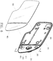
FIG. 6 is a perspective view showing the exploded components of a vehicle rear view mirror assembly according to a third embodiment of the present invention. -
FIG. 7 is a perspective view showing the exploded components of a part of the vehicle rear view mirror assembly according to the third embodiment of the present invention. -
FIG. 8 is a cross sectional view taken along the line 8-8 ofFIG. 6 . - With reference to
FIG. 1 , a vehicle rearview mirror assembly 10 according to a first embodiment of the present invention comprises: abase 20 for fixing amain lens 30 and anauxiliary lens 40 which is a flat lens and is rotated relative to thebase 20 to adjust an angle between theauxiliary lens 40 and themain lens 30. - Referring further to
FIG. 2 , thebase 20 includes apositioning portion 21 defined on one side thereof and formed in a circular groove shape, thepositioning portion 21 has an innerarcuate face 22 defined on an inner wall thereof (as shown inFIG. 3 ) and has alimiting post 23 extending outwardly to theauxiliary lens 40 from a bottom end thereof. Thebase 20 also includes two guidingmembers 24 disposed on an outer wall of thepositioning portion 21, wherein the two guidingmembers 24 are arranged on a straight line A, and each guidingmember 24 has arecess 25 defined therein. - The
auxiliary lens 40 includes a connectingportion 41 for corresponding to thepositioning portion 21 of thebase 20. In this embodiment, the connectingportion 41 is an annular sleeve retained with thepositioning portion 21 and has an outerarcuate face 42 defined on an outer wall thereof to contact with the innerarcuate face 22, such that theauxiliary lens 40 is rotatably fixed in thebase 20. Furthermore, theauxiliary lens 40 also includes two guidedportions 43, each being formed in a column shape to correspond to each of the two guidingmembers 24, such that when theauxiliary lens 40 is fixed in thebase 20, the two guidedportions 43 are inserted into tworecesses 25 of the two guidingmembers 24, and theauxiliary lens 40 is guided by the two guidingmembers 24 to rotate through a virtual plane of the straight line A. - As shown in
FIG. 3 , a rotating angle of theauxiliary lens 40 is limited by thelimiting post 23, in other words, when theauxiliary lens 40 is rotated to a maximum rotating angle, a back surface of theauxiliary lens 40 contacts with a top surface of the limitingpost 23. - It is to be noted that the
positioning portion 21 and the connectingportion 41 is one embodiment of the present invention, any configurations for retaining thepositioning portion 21 with the connectingportion 41 are in a scope of the present invention. - As shown in
FIGS. 4 and5 , a difference of a vehicle rearview mirror assembly 10 of a second embodiment from that of the first embodiment comprises: a cusp-shaped extendingsection 44 extending to themain lens 30 from a lower side of theauxiliary lens 40, thus increasing a visible range. - As shown in
FIG. 6 , a vehicle rearview mirror assembly 101 according a third embodiment of the present invention comprises: abase 201 for fixing amain lens 301 and anauxiliary lens 401 which is a flat lens and is rotated relative to thebase 201 to adjust an angle between theauxiliary lens 401 and themain lens 301. - With reference to
FIG. 7 , thebase 201 includes apositioning portion 211 defined on one side thereof and formed in a circular groove shape, thepositioning portion 211 has an innerarcuate face 221 defined on an inner wall thereof (as shown inFIG. 8 ) and has alimiting post 231 extending outwardly to theauxiliary lens 401 from a bottom end thereof and connecting with aconfining element 501. Thebase 201 also includes two guidingmembers 241 disposed on an outer wall of thepositioning portion 211, wherein the two guidingmembers 241 are arranged on a straight line A. - The
auxiliary lens 401 includes a connectingportion 411 for corresponding to thepositioning portion 211 of thebase 201. In this embodiment, the connectingportion 411 is a semispherical block retained with thepositioning portion 211 and has an outer arcuate face defined on an outer wall thereof to contact with the innerarcuate face 221, such that theauxiliary lens 401 is rotatably fixed in thebase 201. Furthermore, theauxiliary lens 401 also includes two guidedportions 431, each being formed in a notch shape to correspond to each of the two guidingmembers 241, such that when theauxiliary lens 401 is fixed in thebase 201, the two guidedportions 431 are inserted into the two guidingmembers 241, and theauxiliary lens 401 is guided by the two guidingmembers 241 to rotate through a virtual plane of the straight line. - Thereby, after the main lens is adjusted toward a desired position by a driver, the auxiliary lens is rotated further to adjust the angle between the auxiliary lens and the main lens, thus increasing the visible range.
Claims (9)
- A vehicle rear view mirror assembly (10, 101) comprising: a base (20, 201) for fixing a main lens (30, 301) and an auxiliary lens (40, 401),
the base (20, 201) including a positioning portion (21, 211) defined on one side thereof, the auxiliary lens (40, 401) includes a connecting portion (41, 411) for corresponding to the positioning portion (21, 211) of the base (20, 201), such that the auxiliary lens (40, 401) is rotatably fixed in the positioning portion (21, 211) of the base, wherein the base (20, 201) includes a flat face arranged on a main portion of the base (20, 201) and configured to connect with the main lens (30, 301), and the base (20, 201) also includes a second face, wherein the second face has the positioning portion (21, 211); characterized in that the second face of the base (20, 201) extends from the one side of the base (20, 201) in parallel to the flat face but in a different plane so that the second face is lower than the main flat face of the base (20, 201) so that the auxiliary lens (40, 401), which is a flat lens, after being connected with the positioning portion (21, 211) is adjustable to be arranged in a way so that the auxiliary lens (40) extends in parallel to the main lens (30, 301). - The vehicle rear view mirror assembly (10, 101) as claimed in claim 1, wherein the positioning portion (21, 211) is formed in a groove shape and has an inner arcuate face (22, 221) defined on an inner wall thereof, the connecting portion (41, 411) is a sleeve retained with the positioning portion (21, 211) and has an outer arcuate face (42) defined on an outer wall thereof to contact with the inner arcuate face (22, 221).
- The vehicle rear view mirror assembly (10, 101) as claimed in claim 2, wherein the groove is circular, and the sleeve is annular.
- The vehicle rear view mirror assembly (10, 101) as claimed in claim 1 or 2, wherein the base (20, 201) also includes at least one guiding member (24, 241) disposed on an outer wall of the positioning portion (21, 211), and the auxiliary lens (40, 401) also includes at least one guided portion (43, 431) for corresponding to the at least one guiding member (24, 241).
- The vehicle rear view mirror assembly (10, 101) as claimed in claim 4, wherein each of the at least one guiding member (24, 241) has a recess (25) defined therein, and each of the at least one guided portion (43, 431) is formed in a column shape to insert into the recess (25).
- The vehicle rear view mirror assembly (10, 101) as claimed in claim 5, wherein a number of the at least one guiding member (24, 241) is two, a number of the at least one guided portion (43, 431) is two, and the two guiding members (24, 241) are arranged on a straight line.
- The vehicle rear view mirror assembly (10, 101) as claimed in claim 6, wherein the positioning portion (21, 211) has a limiting post (23, 231) extending outwardly to the auxiliary lens (40, 401) from a bottom end thereof.
- The vehicle rear view mirror assembly (10, 101) as claimed in claim 1, wherein the auxiliary lens (40, 401) further includes an extending section (44) extending to the main lens (30, 301) from a lower side thereof.
- The vehicle rear view mirror assembly (10, 101) as claimed in claim 8, wherein the extending section (44) is formed in a cusp shape.
Applications Claiming Priority (1)
| Application Number | Priority Date | Filing Date | Title |
|---|---|---|---|
| TW102224330U TWM480489U (en) | 2013-12-24 | 2013-12-24 | Improved structure of vehicle side-view mirror |
Publications (2)
| Publication Number | Publication Date |
|---|---|
| EP2889183A1 EP2889183A1 (en) | 2015-07-01 |
| EP2889183B1 true EP2889183B1 (en) | 2018-06-13 |
Family
ID=51395765
Family Applications (1)
| Application Number | Title | Priority Date | Filing Date |
|---|---|---|---|
| EP14198076.3A Active EP2889183B1 (en) | 2013-12-24 | 2014-12-15 | Vehicle rear view mirror assembly |
Country Status (7)
| Country | Link |
|---|---|
| EP (1) | EP2889183B1 (en) |
| JP (1) | JP3191969U (en) |
| KR (1) | KR20150075044A (en) |
| CN (1) | CN203946028U (en) |
| ES (1) | ES2680223T3 (en) |
| PH (1) | PH12014000372B1 (en) |
| TW (1) | TWM480489U (en) |
Families Citing this family (1)
| Publication number | Priority date | Publication date | Assignee | Title |
|---|---|---|---|---|
| US11679721B2 (en) | 2021-03-12 | 2023-06-20 | Motherson Innovations Company Limited | Rear view device with multi-piece backing plate |
Family Cites Families (6)
| Publication number | Priority date | Publication date | Assignee | Title |
|---|---|---|---|---|
| US4714322A (en) * | 1986-03-03 | 1987-12-22 | Charles Cook | Rear view mirror with day/night setting and adjustable panoramic view |
| BR8900142A (en) * | 1989-01-10 | 1990-08-14 | Metagal Industria E Comercio Ltda. | IMPROVEMENTS IN EXTERNAL REAR-VIEW MIRROR FOR VEHICLES |
| US5295021A (en) * | 1993-04-19 | 1994-03-15 | Arthur P. Swanson | Triple exterior rearview vehicle mirror |
| US5432643A (en) * | 1994-08-08 | 1995-07-11 | Huang; Chi S. | Auxiliary mirror assembly for rear view mirror |
| US5946151A (en) * | 1997-03-17 | 1999-08-31 | Siegel-Robert, Inc. | Automobile pivotal mirror mounting assembly |
| JP3781714B2 (en) * | 2002-11-01 | 2006-05-31 | 株式会社アトラスオート | door mirror |
-
2013
- 2013-12-24 TW TW102224330U patent/TWM480489U/en not_active IP Right Cessation
-
2014
- 2014-01-26 CN CN201420050301.0U patent/CN203946028U/en not_active Expired - Fee Related
- 2014-04-16 JP JP2014001982U patent/JP3191969U/en not_active Expired - Fee Related
- 2014-12-09 PH PH12014000372A patent/PH12014000372B1/en unknown
- 2014-12-15 EP EP14198076.3A patent/EP2889183B1/en active Active
- 2014-12-15 ES ES14198076.3T patent/ES2680223T3/en active Active
- 2014-12-23 KR KR1020140187341A patent/KR20150075044A/en not_active Application Discontinuation
Non-Patent Citations (1)
| Title |
|---|
| None * |
Also Published As
| Publication number | Publication date |
|---|---|
| EP2889183A1 (en) | 2015-07-01 |
| PH12014000372A1 (en) | 2016-06-13 |
| PH12014000372B1 (en) | 2016-06-13 |
| CN203946028U (en) | 2014-11-19 |
| KR20150075044A (en) | 2015-07-02 |
| TWM480489U (en) | 2014-06-21 |
| ES2680223T3 (en) | 2018-09-05 |
| JP3191969U (en) | 2014-07-24 |
Similar Documents
| Publication | Publication Date | Title |
|---|---|---|
| ES2309866T3 (en) | OUTDOOR REAR VIEW MIRROR WITH ADJUSTMENT DEVICE. | |
| KR20170107385A (en) | A ball joint | |
| US10220753B2 (en) | Vehicle headrest structure | |
| US7419260B1 (en) | Eyeglass assembly | |
| US20170153456A1 (en) | Universal joint module and head-mounted display device | |
| CN105914082A (en) | Switch device | |
| USD847091S1 (en) | Housing for cable transition assembly | |
| EP2889183B1 (en) | Vehicle rear view mirror assembly | |
| US10647259B2 (en) | Rearview mirror structure for vehicle | |
| JP2010083464A (en) | In-vehicle device and holding member | |
| US9676322B2 (en) | Light linking system | |
| JP5632967B2 (en) | Vehicle mounted camera | |
| ES2268529T3 (en) | ARTICULATED INTERLOCK UNION. | |
| JP2011124097A (en) | Vehicular lamp | |
| ES2265288B1 (en) | ACCELERATOR PEDAL ADJUSTMENT MECHANISM. | |
| US20130188121A1 (en) | Eyeglasses | |
| US20190077317A1 (en) | Vehicle visual recognition device | |
| ES2204286B1 (en) | PEDAL ADJUSTMENT MECHANISM. | |
| US20160004093A1 (en) | Hinge joint for eyeglasses | |
| USD891666S1 (en) | Prismatic light fixture | |
| CN207571387U (en) | Vehicle-mounted head-up display device | |
| US20150258938A1 (en) | Rear-view mirror assembly | |
| JP2016097961A (en) | Mirror actuator of vehicle | |
| JPWO2017221914A1 (en) | Blind spot assist device | |
| ES2270692B1 (en) | MIRROR SYSTEM COMPLETELY INTEGRATED INSIDE THE CAR. |
Legal Events
| Date | Code | Title | Description |
|---|---|---|---|
| PUAI | Public reference made under article 153(3) epc to a published international application that has entered the european phase |
Free format text: ORIGINAL CODE: 0009012 |
|
| 17P | Request for examination filed |
Effective date: 20141215 |
|
| AK | Designated contracting states |
Kind code of ref document: A1 Designated state(s): AL AT BE BG CH CY CZ DE DK EE ES FI FR GB GR HR HU IE IS IT LI LT LU LV MC MK MT NL NO PL PT RO RS SE SI SK SM TR |
|
| AX | Request for extension of the european patent |
Extension state: BA ME |
|
| R17P | Request for examination filed (corrected) |
Effective date: 20160104 |
|
| RBV | Designated contracting states (corrected) |
Designated state(s): AL AT BE BG CH CY CZ DE DK EE ES FI FR GB GR HR HU IE IS IT LI LT LU LV MC MK MT NL NO PL PT RO RS SE SI SK SM TR |
|
| 17Q | First examination report despatched |
Effective date: 20160909 |
|
| GRAP | Despatch of communication of intention to grant a patent |
Free format text: ORIGINAL CODE: EPIDOSNIGR1 |
|
| INTG | Intention to grant announced |
Effective date: 20171222 |
|
| GRAS | Grant fee paid |
Free format text: ORIGINAL CODE: EPIDOSNIGR3 |
|
| GRAA | (expected) grant |
Free format text: ORIGINAL CODE: 0009210 |
|
| AK | Designated contracting states |
Kind code of ref document: B1 Designated state(s): AL AT BE BG CH CY CZ DE DK EE ES FI FR GB GR HR HU IE IS IT LI LT LU LV MC MK MT NL NO PL PT RO RS SE SI SK SM TR |
|
| REG | Reference to a national code |
Ref country code: GB Ref legal event code: FG4D |
|
| REG | Reference to a national code |
Ref country code: CH Ref legal event code: EP Ref country code: AT Ref legal event code: REF Ref document number: 1008150 Country of ref document: AT Kind code of ref document: T Effective date: 20180615 |
|
| REG | Reference to a national code |
Ref country code: IE Ref legal event code: FG4D |
|
| REG | Reference to a national code |
Ref country code: DE Ref legal event code: R096 Ref document number: 602014026902 Country of ref document: DE |
|
| REG | Reference to a national code |
Ref country code: ES Ref legal event code: FG2A Ref document number: 2680223 Country of ref document: ES Kind code of ref document: T3 Effective date: 20180905 |
|
| REG | Reference to a national code |
Ref country code: SE Ref legal event code: TRGR |
|
| REG | Reference to a national code |
Ref country code: NL Ref legal event code: MP Effective date: 20180613 |
|
| REG | Reference to a national code |
Ref country code: LT Ref legal event code: MG4D |
|
| PG25 | Lapsed in a contracting state [announced via postgrant information from national office to epo] |
Ref country code: FI Free format text: LAPSE BECAUSE OF FAILURE TO SUBMIT A TRANSLATION OF THE DESCRIPTION OR TO PAY THE FEE WITHIN THE PRESCRIBED TIME-LIMIT Effective date: 20180613 Ref country code: LT Free format text: LAPSE BECAUSE OF FAILURE TO SUBMIT A TRANSLATION OF THE DESCRIPTION OR TO PAY THE FEE WITHIN THE PRESCRIBED TIME-LIMIT Effective date: 20180613 Ref country code: BG Free format text: LAPSE BECAUSE OF FAILURE TO SUBMIT A TRANSLATION OF THE DESCRIPTION OR TO PAY THE FEE WITHIN THE PRESCRIBED TIME-LIMIT Effective date: 20180913 Ref country code: NO Free format text: LAPSE BECAUSE OF FAILURE TO SUBMIT A TRANSLATION OF THE DESCRIPTION OR TO PAY THE FEE WITHIN THE PRESCRIBED TIME-LIMIT Effective date: 20180913 Ref country code: CY Free format text: LAPSE BECAUSE OF FAILURE TO SUBMIT A TRANSLATION OF THE DESCRIPTION OR TO PAY THE FEE WITHIN THE PRESCRIBED TIME-LIMIT Effective date: 20180613 |
|
| PG25 | Lapsed in a contracting state [announced via postgrant information from national office to epo] |
Ref country code: GR Free format text: LAPSE BECAUSE OF FAILURE TO SUBMIT A TRANSLATION OF THE DESCRIPTION OR TO PAY THE FEE WITHIN THE PRESCRIBED TIME-LIMIT Effective date: 20180914 Ref country code: RS Free format text: LAPSE BECAUSE OF FAILURE TO SUBMIT A TRANSLATION OF THE DESCRIPTION OR TO PAY THE FEE WITHIN THE PRESCRIBED TIME-LIMIT Effective date: 20180613 Ref country code: HR Free format text: LAPSE BECAUSE OF FAILURE TO SUBMIT A TRANSLATION OF THE DESCRIPTION OR TO PAY THE FEE WITHIN THE PRESCRIBED TIME-LIMIT Effective date: 20180613 Ref country code: LV Free format text: LAPSE BECAUSE OF FAILURE TO SUBMIT A TRANSLATION OF THE DESCRIPTION OR TO PAY THE FEE WITHIN THE PRESCRIBED TIME-LIMIT Effective date: 20180613 |
|
| REG | Reference to a national code |
Ref country code: AT Ref legal event code: MK05 Ref document number: 1008150 Country of ref document: AT Kind code of ref document: T Effective date: 20180613 |
|
| PG25 | Lapsed in a contracting state [announced via postgrant information from national office to epo] |
Ref country code: NL Free format text: LAPSE BECAUSE OF FAILURE TO SUBMIT A TRANSLATION OF THE DESCRIPTION OR TO PAY THE FEE WITHIN THE PRESCRIBED TIME-LIMIT Effective date: 20180613 |
|
| PG25 | Lapsed in a contracting state [announced via postgrant information from national office to epo] |
Ref country code: AT Free format text: LAPSE BECAUSE OF FAILURE TO SUBMIT A TRANSLATION OF THE DESCRIPTION OR TO PAY THE FEE WITHIN THE PRESCRIBED TIME-LIMIT Effective date: 20180613 Ref country code: IS Free format text: LAPSE BECAUSE OF FAILURE TO SUBMIT A TRANSLATION OF THE DESCRIPTION OR TO PAY THE FEE WITHIN THE PRESCRIBED TIME-LIMIT Effective date: 20181013 Ref country code: EE Free format text: LAPSE BECAUSE OF FAILURE TO SUBMIT A TRANSLATION OF THE DESCRIPTION OR TO PAY THE FEE WITHIN THE PRESCRIBED TIME-LIMIT Effective date: 20180613 Ref country code: SK Free format text: LAPSE BECAUSE OF FAILURE TO SUBMIT A TRANSLATION OF THE DESCRIPTION OR TO PAY THE FEE WITHIN THE PRESCRIBED TIME-LIMIT Effective date: 20180613 Ref country code: CZ Free format text: LAPSE BECAUSE OF FAILURE TO SUBMIT A TRANSLATION OF THE DESCRIPTION OR TO PAY THE FEE WITHIN THE PRESCRIBED TIME-LIMIT Effective date: 20180613 Ref country code: RO Free format text: LAPSE BECAUSE OF FAILURE TO SUBMIT A TRANSLATION OF THE DESCRIPTION OR TO PAY THE FEE WITHIN THE PRESCRIBED TIME-LIMIT Effective date: 20180613 Ref country code: PL Free format text: LAPSE BECAUSE OF FAILURE TO SUBMIT A TRANSLATION OF THE DESCRIPTION OR TO PAY THE FEE WITHIN THE PRESCRIBED TIME-LIMIT Effective date: 20180613 |
|
| PG25 | Lapsed in a contracting state [announced via postgrant information from national office to epo] |
Ref country code: SM Free format text: LAPSE BECAUSE OF FAILURE TO SUBMIT A TRANSLATION OF THE DESCRIPTION OR TO PAY THE FEE WITHIN THE PRESCRIBED TIME-LIMIT Effective date: 20180613 |
|
| REG | Reference to a national code |
Ref country code: DE Ref legal event code: R097 Ref document number: 602014026902 Country of ref document: DE |
|
| PLBE | No opposition filed within time limit |
Free format text: ORIGINAL CODE: 0009261 |
|
| STAA | Information on the status of an ep patent application or granted ep patent |
Free format text: STATUS: NO OPPOSITION FILED WITHIN TIME LIMIT |
|
| 26N | No opposition filed |
Effective date: 20190314 |
|
| PG25 | Lapsed in a contracting state [announced via postgrant information from national office to epo] |
Ref country code: SI Free format text: LAPSE BECAUSE OF FAILURE TO SUBMIT A TRANSLATION OF THE DESCRIPTION OR TO PAY THE FEE WITHIN THE PRESCRIBED TIME-LIMIT Effective date: 20180613 Ref country code: DK Free format text: LAPSE BECAUSE OF FAILURE TO SUBMIT A TRANSLATION OF THE DESCRIPTION OR TO PAY THE FEE WITHIN THE PRESCRIBED TIME-LIMIT Effective date: 20180613 |
|
| REG | Reference to a national code |
Ref country code: CH Ref legal event code: PL |
|
| PG25 | Lapsed in a contracting state [announced via postgrant information from national office to epo] |
Ref country code: MC Free format text: LAPSE BECAUSE OF FAILURE TO SUBMIT A TRANSLATION OF THE DESCRIPTION OR TO PAY THE FEE WITHIN THE PRESCRIBED TIME-LIMIT Effective date: 20180613 Ref country code: LU Free format text: LAPSE BECAUSE OF NON-PAYMENT OF DUE FEES Effective date: 20181215 |
|
| REG | Reference to a national code |
Ref country code: IE Ref legal event code: MM4A |
|
| REG | Reference to a national code |
Ref country code: BE Ref legal event code: MM Effective date: 20181231 |
|
| PG25 | Lapsed in a contracting state [announced via postgrant information from national office to epo] |
Ref country code: IE Free format text: LAPSE BECAUSE OF NON-PAYMENT OF DUE FEES Effective date: 20181215 |
|
| PG25 | Lapsed in a contracting state [announced via postgrant information from national office to epo] |
Ref country code: AL Free format text: LAPSE BECAUSE OF FAILURE TO SUBMIT A TRANSLATION OF THE DESCRIPTION OR TO PAY THE FEE WITHIN THE PRESCRIBED TIME-LIMIT Effective date: 20180613 Ref country code: BE Free format text: LAPSE BECAUSE OF NON-PAYMENT OF DUE FEES Effective date: 20181231 |
|
| PG25 | Lapsed in a contracting state [announced via postgrant information from national office to epo] |
Ref country code: CH Free format text: LAPSE BECAUSE OF NON-PAYMENT OF DUE FEES Effective date: 20181231 Ref country code: LI Free format text: LAPSE BECAUSE OF NON-PAYMENT OF DUE FEES Effective date: 20181231 |
|
| PG25 | Lapsed in a contracting state [announced via postgrant information from national office to epo] |
Ref country code: MT Free format text: LAPSE BECAUSE OF NON-PAYMENT OF DUE FEES Effective date: 20181215 |
|
| PG25 | Lapsed in a contracting state [announced via postgrant information from national office to epo] |
Ref country code: PT Free format text: LAPSE BECAUSE OF FAILURE TO SUBMIT A TRANSLATION OF THE DESCRIPTION OR TO PAY THE FEE WITHIN THE PRESCRIBED TIME-LIMIT Effective date: 20180613 |
|
| PG25 | Lapsed in a contracting state [announced via postgrant information from national office to epo] |
Ref country code: MK Free format text: LAPSE BECAUSE OF NON-PAYMENT OF DUE FEES Effective date: 20180613 Ref country code: HU Free format text: LAPSE BECAUSE OF FAILURE TO SUBMIT A TRANSLATION OF THE DESCRIPTION OR TO PAY THE FEE WITHIN THE PRESCRIBED TIME-LIMIT; INVALID AB INITIO Effective date: 20141215 |
|
| PGFP | Annual fee paid to national office [announced via postgrant information from national office to epo] |
Ref country code: DE Payment date: 20201207 Year of fee payment: 7 Ref country code: SE Payment date: 20201221 Year of fee payment: 7 Ref country code: GB Payment date: 20201222 Year of fee payment: 7 Ref country code: FR Payment date: 20201218 Year of fee payment: 7 |
|
| PGFP | Annual fee paid to national office [announced via postgrant information from national office to epo] |
Ref country code: IT Payment date: 20201230 Year of fee payment: 7 |
|
| PGFP | Annual fee paid to national office [announced via postgrant information from national office to epo] |
Ref country code: ES Payment date: 20210122 Year of fee payment: 7 Ref country code: TR Payment date: 20201209 Year of fee payment: 7 |
|
| REG | Reference to a national code |
Ref country code: DE Ref legal event code: R119 Ref document number: 602014026902 Country of ref document: DE |
|
| REG | Reference to a national code |
Ref country code: SE Ref legal event code: EUG |
|
| GBPC | Gb: european patent ceased through non-payment of renewal fee |
Effective date: 20211215 |
|
| PG25 | Lapsed in a contracting state [announced via postgrant information from national office to epo] |
Ref country code: SE Free format text: LAPSE BECAUSE OF NON-PAYMENT OF DUE FEES Effective date: 20211216 Ref country code: GB Free format text: LAPSE BECAUSE OF NON-PAYMENT OF DUE FEES Effective date: 20211215 Ref country code: DE Free format text: LAPSE BECAUSE OF NON-PAYMENT OF DUE FEES Effective date: 20220701 |
|
| PG25 | Lapsed in a contracting state [announced via postgrant information from national office to epo] |
Ref country code: FR Free format text: LAPSE BECAUSE OF NON-PAYMENT OF DUE FEES Effective date: 20211231 |
|
| PG25 | Lapsed in a contracting state [announced via postgrant information from national office to epo] |
Ref country code: IT Free format text: LAPSE BECAUSE OF NON-PAYMENT OF DUE FEES Effective date: 20211215 |
|
| REG | Reference to a national code |
Ref country code: ES Ref legal event code: FD2A Effective date: 20230228 |
|
| PG25 | Lapsed in a contracting state [announced via postgrant information from national office to epo] |
Ref country code: ES Free format text: LAPSE BECAUSE OF NON-PAYMENT OF DUE FEES Effective date: 20211216 |