JP2006103674A - Brake control device for bicycle with electric operation member - Google Patents
Brake control device for bicycle with electric operation member Download PDFInfo
- Publication number
- JP2006103674A JP2006103674A JP2005277971A JP2005277971A JP2006103674A JP 2006103674 A JP2006103674 A JP 2006103674A JP 2005277971 A JP2005277971 A JP 2005277971A JP 2005277971 A JP2005277971 A JP 2005277971A JP 2006103674 A JP2006103674 A JP 2006103674A
- Authority
- JP
- Japan
- Prior art keywords
- brake control
- brake
- control device
- bicycle
- lever
- Prior art date
- Legal status (The legal status is an assumption and is not a legal conclusion. Google has not performed a legal analysis and makes no representation as to the accuracy of the status listed.)
- Withdrawn
Links
- 239000000463 material Substances 0.000 claims description 4
- 230000004048 modification Effects 0.000 description 12
- 238000012986 modification Methods 0.000 description 12
- 230000007246 mechanism Effects 0.000 description 7
- 230000008859 change Effects 0.000 description 2
- 230000007935 neutral effect Effects 0.000 description 2
- 230000005540 biological transmission Effects 0.000 description 1
- 238000010276 construction Methods 0.000 description 1
- 210000003811 finger Anatomy 0.000 description 1
- 210000004247 hand Anatomy 0.000 description 1
- 230000006872 improvement Effects 0.000 description 1
- 230000007257 malfunction Effects 0.000 description 1
- 239000002184 metal Substances 0.000 description 1
- 230000002093 peripheral effect Effects 0.000 description 1
- 230000009467 reduction Effects 0.000 description 1
- 239000000725 suspension Substances 0.000 description 1
- 210000003813 thumb Anatomy 0.000 description 1
Images


Classifications
-
- B—PERFORMING OPERATIONS; TRANSPORTING
- B62—LAND VEHICLES FOR TRAVELLING OTHERWISE THAN ON RAILS
- B62M—RIDER PROPULSION OF WHEELED VEHICLES OR SLEDGES; POWERED PROPULSION OF SLEDGES OR SINGLE-TRACK CYCLES; TRANSMISSIONS SPECIALLY ADAPTED FOR SUCH VEHICLES
- B62M25/00—Actuators for gearing speed-change mechanisms specially adapted for cycles
- B62M25/08—Actuators for gearing speed-change mechanisms specially adapted for cycles with electrical or fluid transmitting systems
-
- B—PERFORMING OPERATIONS; TRANSPORTING
- B62—LAND VEHICLES FOR TRAVELLING OTHERWISE THAN ON RAILS
- B62K—CYCLES; CYCLE FRAMES; CYCLE STEERING DEVICES; RIDER-OPERATED TERMINAL CONTROLS SPECIALLY ADAPTED FOR CYCLES; CYCLE AXLE SUSPENSIONS; CYCLE SIDE-CARS, FORECARS, OR THE LIKE
- B62K23/00—Rider-operated controls specially adapted for cycles, i.e. means for initiating control operations, e.g. levers, grips
- B62K23/02—Rider-operated controls specially adapted for cycles, i.e. means for initiating control operations, e.g. levers, grips hand actuated
- B62K23/06—Levers
-
- B—PERFORMING OPERATIONS; TRANSPORTING
- B62—LAND VEHICLES FOR TRAVELLING OTHERWISE THAN ON RAILS
- B62L—BRAKES SPECIALLY ADAPTED FOR CYCLES
- B62L3/00—Brake-actuating mechanisms; Arrangements thereof
- B62L3/02—Brake-actuating mechanisms; Arrangements thereof for control by a hand lever
-
- Y—GENERAL TAGGING OF NEW TECHNOLOGICAL DEVELOPMENTS; GENERAL TAGGING OF CROSS-SECTIONAL TECHNOLOGIES SPANNING OVER SEVERAL SECTIONS OF THE IPC; TECHNICAL SUBJECTS COVERED BY FORMER USPC CROSS-REFERENCE ART COLLECTIONS [XRACs] AND DIGESTS
- Y10—TECHNICAL SUBJECTS COVERED BY FORMER USPC
- Y10T—TECHNICAL SUBJECTS COVERED BY FORMER US CLASSIFICATION
- Y10T74/00—Machine element or mechanism
- Y10T74/20—Control lever and linkage systems
- Y10T74/20396—Hand operated
- Y10T74/20402—Flexible transmitter [e.g., Bowden cable]
- Y10T74/2042—Flexible transmitter [e.g., Bowden cable] and hand operator
- Y10T74/20438—Single rotatable lever [e.g., for bicycle brake or derailleur]
Abstract
Description
本発明は、自転車用ブレーキ制御装置、特に、人間工学に基づいて設計されたブレーキ制御装置のブレーキレバーに動作可能に連結された電気操作部材を備える自転車用ブレーキ制御装置に関する。 The present invention relates to a bicycle brake control device, and more particularly to a bicycle brake control device including an electric operation member operably connected to a brake lever of a brake control device designed based on ergonomics.
自転車に乗ることは、移動の手段であるとともに、レクレーションの形態としてもますます人気が高まっている。また、自転車に乗ることは、プロ、アマを問わず、競技スポーツとしても人気が高い。レクレーション、移動、競技の用途に関わらず、自転車産業において、種々の自転車部品は常に改良が続けられている。絶えず設計が見直されている自転車部品の一つとして、自転車用ブレーキ制御装置が挙げられる。 Riding a bicycle is a means of movement and is also becoming increasingly popular as a form of recreation. Bicycling is a popular sport for both professionals and amateurs. Regardless of recreational, mobile or competition applications, various bicycle components are constantly being improved in the bicycle industry. One bicycle component that is constantly being reviewed is a bicycle brake control device.
一般に、自転車用ブレーキ制御装置は、ブラケットに回動自在に連結されたレバーを有している。ブラケットは、通常、ハンドルバーに固定されている。レバーを操作することによってブレーキケーブルが引っ張られ、従来のブレーキ制御装置は作動する。近年、シフト装置には、ブレーキ制御装置が組み込まれている。ブレーキ制御装置が組み込まれたシフト装置は、通常、機械的シフトケーブルを引っ張ったり解放したりするためにブラケットに対して相対的に移動する機械式のレバーである。したがって、ライダーは、それぞれのブレーキ制御装置によって、ブレーキ装置およびディレーラの両方を操作することができる。近年、自転車は、電子部品を装備するようにもなってきている。これらの部品は、一般に、ハンドルバー等に装着される電気制御装置によって操作される。
これらの従来のブレーキ装置、シフト装置および電子制御装置は十分な機能を有しているものの、必ずしもライダーが操作することに対して使いやすいものではなく快適なものでもない。具体的には、ライダーは、ハンドルバーにおいて様々な位置に手を移動させて、これらの種々の装置を操作する。あるいは、ライダーが手を様々な位置に移動させる必要がない場合でも、これらの種々の装置を操作することが容易ではなかったり快適でなかったりする。 Although these conventional brake devices, shift devices and electronic control devices have sufficient functions, they are not always easy to use and comfortable for the rider to operate. Specifically, the rider moves these hands to various positions on the handlebar and operates these various devices. Alternatively, even when the rider does not need to move his hand to various positions, it is not easy or comfortable to operate these various devices.
本開示から本技術に精通するものには明らかであるが、上記視点から電気操作部材を備える自転車用ブレーキ装置の改良が必要であることがわかる。本発明では、本技術におけるこの必要性ならびにその他の必要性が示され、本開示によって当業者はそれらを明確に理解することができる。 Although it is obvious to those skilled in the art from the present disclosure, it can be seen from the above viewpoint that an improvement of a bicycle brake device including an electric operation member is necessary. The present invention addresses this need as well as other needs in the art, which can be clearly understood by those skilled in the art through this disclosure.
本発明の目的は、人間工学に基づいて設計された電気制御部材を備える自転車用ブレーキ装置を提供することにある。 An object of the present invention is to provide a bicycle brake device including an electric control member designed based on ergonomics.
また、本発明の目的は、操作しやすい電気制御部材を備える自転車用ブレーキ装置を提供することにある。 Moreover, the objective of this invention is providing the brake device for bicycles provided with the electric control member which is easy to operate.
また、本発明の目的は、ライダーがブレーキおよび変速操作を行うことが容易である電気制御部材を備える比較的コンパクトな自転車用ブレーキ制御装置を提供することにある。 It is another object of the present invention to provide a relatively compact bicycle brake control device including an electric control member that allows a rider to easily perform a brake and a shift operation.
さらに、本発明の目的は、構成が比較的簡単で製造および/または組み立てが低コストで行える電気制御部材を備える自転車用ブレーキ装置を提供することにある。 It is a further object of the present invention to provide a bicycle brake device including an electric control member that is relatively simple in construction and can be manufactured and / or assembled at low cost.
以上の目的は、主に、ブレーキレバーブラケットと、ブレーキ制御レバーと、電気操作部材とを備える自転車用ブレーキ制御装置を提供することによって達成できる。ブレーキレバーブラケットは、自転車用ハンドルバーの装着部に取り付けられ固定される。ブレーキ制御レバーは、ブレーキレバーブラケットに回動自在に連結されて、ブレーキ面に沿ってレスト位置からブレーキ位置へハンドルバーに向かってピボット軸回りに移動する。ブレーキ制御レバーは、ブレーキレバーブラケットに回動自在に連結される基端部と、基端部から延びる末端部とを有する。電気操作部材は、制御レバーの末端部に移動可能に連結されて、電気的に自転車部品を操作する。ブレーキ制御レバーの末端部は、ブレーキ面に対して垂直方向に見ると、基端部の横方向の最も外側の基端側端部から横方向外側に位置する横方向の最も外側の末端側端部を有している。操作部材は、ブレーキ制御レバーがブレーキ位置に位置するとき、ブレーキ面に対して垂直方向に見ると装着部のハンドルバー中心線から横方向外側に位置している。 The above object can be achieved mainly by providing a bicycle brake control device including a brake lever bracket, a brake control lever, and an electric operation member. The brake lever bracket is attached and fixed to the mounting portion of the bicycle handlebar. The brake control lever is rotatably connected to the brake lever bracket, and moves around the pivot axis from the rest position to the brake position along the brake surface toward the handlebar. The brake control lever has a base end portion that is rotatably connected to the brake lever bracket, and a distal end portion that extends from the base end portion. The electric operation member is movably connected to the end of the control lever to electrically operate the bicycle component. The distal end of the brake control lever, when viewed in the direction perpendicular to the brake surface, is the laterally outermost distal end located laterally outward from the laterally outermost proximal end of the proximal end. Has a part. When the brake control lever is located at the brake position, the operation member is located laterally outward from the handlebar center line of the mounting portion when viewed in the direction perpendicular to the brake surface.
本発明のその他の目的、特徴、態様、利点は、添付された図面と共に、以下に開示された本発明の実施形態の詳細な説明から当業者に明らかにされる。 Other objects, features, aspects and advantages of the present invention will become apparent to those skilled in the art from the detailed description of the embodiments of the present invention disclosed below in conjunction with the accompanying drawings.
本発明の自転車用ブレーキ装置は電気制御部材を備えており、電気制御部材は、人間工学に基づいて設計されておりコンパクト化が図られている。また、本自転車用ブレーキ装置では、電気制御部材が人間工学に基づいて設計されているので、ライダーがブレーキ操作および変速操作を、誤動作を効果的に防止しつつ容易に行うことができる。さらに、本自転車用ブレーキ装置は、製造および組み立てを容易に行いやすく低コスト化を実現することができる。 The bicycle brake device of the present invention includes an electric control member, and the electric control member is designed based on ergonomics and is made compact. Further, in the bicycle brake device, since the electric control member is designed based on ergonomics, the rider can easily perform the brake operation and the shift operation while effectively preventing the malfunction. In addition, the bicycle brake device can be easily manufactured and assembled, and can achieve cost reduction.
[実施例1]
本発明にかかる実施例を図面を参照しながら説明することとする。以下の本発明にかかる実施例の説明は単なる例示であって、添付の特許請求の範囲およびそれらの均等物によって決められる本発明を限定するものではないことは、本開示から、当業者には明らかであろう。
[Example 1]
Embodiments according to the present invention will be described with reference to the drawings. It will be apparent to those skilled in the art from this disclosure that the following description of the embodiments of the present invention is illustrative only and is not intended to limit the present invention as defined by the appended claims and their equivalents. It will be clear.
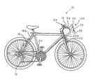
まず、図1および図2には、本発明の第1実施例にかかる、自転車用ハンドルバー14に装着される1組の(つまり左右の)ブレーキ制御装置12R,12L(図1には、一方のみを図示)を備える自転車10が示されている。ブレーキ制御装置12R,12Lのそれぞれは、以下に説明するように、本発明にかかる、人間工学に基づいて設計されたブレーキ制御レバー32を有する。人間工学に基づいて設計されたブレーキ制御レバー32には、自転車用部品を電気的に操作する電気スイッチSが連結されている。
First, FIG. 1 and FIG. 2 show a set of
ハンドルバー14は、横方向部14aと、横方向部14aの両端部に位置する左右の装着部14b,14cとを有する。ハンドルバー中心線Cは、横方向部14aおよび装着部14b,14cの中心を通るようにして延びている。図2からよくわかるように、右側制御装置12Rは装着部14bに連結され、制御装置12Lは装着部14cに連結されている。
The
右手側および左手側ブレーキ制御装置12R,12Lは、それぞれが互いに鏡像関係にあるということを除いて、構成および操作に関してほぼ同一である。したがって、ここでは、ブレーキ制御装置12Rのみの詳細な説明および例示を行うものとする。しかしながら、ブレーキ制御装置12Rの説明および例示がブレーキ制御装置12Lにも同様に当てはまるということは、本開示から当業者には明らかである。また、ここでは、同一の右手側および左手側制御装置12R,12Lの部材あるいは鏡像関係にある右手側および左手側制御装置12R,12Lの部材には、簡単化のため同じ参照符号を付している。
The right hand side and left hand side
例示の実施例においては、以下により詳細に説明するように、電気スイッチSは、自転車用電気制御変速機の部品を操作できるように構成された電気シフト制御スイッチである。しかしながら、必要および/または要望に応じて、電気スイッチSを他の自転車用部品を操作するために利用するということは、本開示から当業者には明らかであろう。例えば、必要および/または要望に応じて、スイッチSを、電気制御サスペンションあるいは他の自転車用部品を操作するために用いることができる。 In the illustrated embodiment, as will be described in more detail below, the electrical switch S is an electrical shift control switch configured to allow operation of parts of a bicycle electrical control transmission. However, it will be apparent to those skilled in the art from this disclosure that the electrical switch S is utilized to operate other bicycle components as needed and / or desired. For example, the switch S can be used to operate an electrically controlled suspension or other bicycle component as needed and / or desired.
図1および図2を参照して、右手側制御装置12Rは、サイクルコンピュータ24を介してリアディレーラ16を操作可能なようにリアディレーラ16に連結されている。一方で、左手側制御装置12Lは、サイクルコンピュータ24を介してフロントディレーラ20を操作可能なようにフロントディレーラ20に連結されている。詳細には、電気スイッチSは、サイクルコンピュータ24に電気的に連結されており、これにより、従来と同様に、ディレーラ16,20は電気的に操作される。また、右手側制御装置12Rは、従来と同様に、ブレーキケーブル18aを介してリアブレーキ装置18に直接的に連結されている。一方で、左手側制御装置12Lは、従来と同様に、ブレーキケーブル22aを介してフロントブレーキ装置22に直接的に連結されている。
Referring to FIGS. 1 and 2, right-hand side control device 12 </ b> R is connected to
サイクルコンピュータ24は、ディレーラ16,20と同様に、当技術分野においては既知のものである。したがって、ここでは、本発明の制御装置12R,12Lの説明に必要となる場合を除いて、サイクルコンピュータ24およびディレーラ16,20の詳細な説明および/または例示はなされない。また、ここでは、自転車10のほとんどの部品が当技術において周知のものあるので、本発明の制御装置12R,12Lに関連する部品を除いて、自転車10のほとんどの部品の詳細な説明または例示はなされない。さらに、詳細に説明および/または例示されていない種々の従来の自転車部品を本発明と組み合わせて使用することができるということは、本開示から、当業者には明らかである。
The
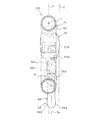
次に、図2から図12に示すように、ブレーキ制御装置12R,12Lのそれぞれは、基本的に、支持部材すなわちブレーキレバーブラケット30と、ブレーキ制御レバー32と、ブレーキレバー付勢部材(図示せず)と、電気操作部材36を有する電気スイッチSと、を備えている。図2からよくわかるように、サイクルコンピュータ24は、1組の電気コード54を介して、制御装置12R,12Lそれぞれの電気スイッチSの電気操作部材36に電気的に接続されている。制御装置12R,12Lは基本的に同一であるので、右側制御装置12Rの詳細な説明のみを行うこととし、左側制御装置12Lの詳細な説明は行わない。
Next, as shown in FIGS. 2 to 12, each of the
制御装置12Rのブレーキレバーブラケット30は、内側壁面30aと、外側壁面30bと、フロント壁面30cと、ボトム壁面30dと、トップ壁面30eと、を有している。図3、図4および図9からよくわかるように、ブレーキレバーブラケット30は、基本的に、剛性支持体すなわちグリップ体40と、バンドすなわちチューブクランプ42と、を備えている。グリップ体40は、従来と同様に、バンドクランプ42によって、自転車用ハンドルバー14に連結され固定される。詳細には、バンドクランプ42は、ハンドルバー14の装着部14bの周りに締め付け装着される。内側壁面30a、フロント壁面30c、ボトム壁面30dおよびトップ壁面30eは、ライダーが手によって握りやすいように設計されたグリップ体40の外周面を形成する。もちろん、必要および/または要望に応じて、他の装着機構を用いてもよいことは、本開示から当業者には明らかであろう。
The
ブレーキ制御レバー32とグリップ体40との間にはバネ(図示せず)が装着されている。このバネは、ブレーキ制御レバー32を、ブレーキ位置(図9および図10を参照)から通常のレスト(ブレーキがかかっていない)位置(図2から図5を参照)へと、従来と同様に付勢する。詳細には、ブレーキ制御レバー32は、グリップ体40に、ブレーキピボット軸Aを有するピボットピン42の回りに回動可能に連結されている。ライダーは、ブレーキ制御レバー32をハンドルバー14に向けてブレーキ操作面Pに沿って引っ張るすなわち握ることによって、ブレーキ制御レバー32をピボット軸Aの回りに回動させる。すると、従来と同様に、ブレーキケーブル18aのインナーワイヤが引っ張られる。ここで、ブレーキ操作面Pは、ピボット軸Aに対して垂直であり、ハンドルバー14の装着部14bの中心線Cにほぼ一致する。また、ブレーキピボット軸Aは、ブレーキレバーブラケット30に対して横断方向に延びている。
A spring (not shown) is mounted between the
図2から図12に示すように、ブレーキ制御レバー32は、基本的に、基端部44と、末端部46と、末端部46と基端部44との間に位置する中間部48とを備えている。中間部48は、末端部46を基端部44に対して実質的に平行な状態で基端部44からオフセットするように形成されている。基端部44、末端部46および中間部48は、金属あるいは当技術分野の既知の他の適切な材料などの軽量かつ高剛性の材料を用いて、ワンピースの単一部材として一体に形成されてることが好ましい。電気スイッチSは、別体構成とし、ブレーキ制御レバー32に固定されていることが好ましい。
As shown in FIGS. 2 to 12, the
電気スイッチSは、ブレーキ制御レバー32の末端部46に連結され固定されていることが好ましい。例示の実施例においては、電気スイッチSは、中間部48に取り付けられ固定されている。ブレーキ制御レバー32がレスト位置とブレーキ位置との間で移動させられるとき、一般的に、電気スイッチSはブレーキ制御レバー32とともに移動する。一方で、以下に説明するように、電気操作部材36は、ブレーキ制御レバー32に対して相対的に移動可能である。電気スイッチSが電気操作部材36と電気的に接続されている限り、電気スイッチSおよび/または電気スイッチSの一部は、電気操作部材36ではなく自転車10の適切な部分に連結して固定するようにしてもよい。
The electrical switch S is preferably connected and fixed to the
基端部44は、ブレーキレバーブラケット30に回動自在に連結されている。ブレーキレバーブラケット30は、基端部44の少なくとも一部ここでは大部分がブレーキレバーブラケット30内に完全に収容できるように形成されている。基端部44は、実質的にブレーキ操作面Pに沿って一方向に延びている。詳細には、基端部44は基端中心長手方向軸X1を有しており、この基端中心長手方向軸X1は、基端部44に沿うように中心に位置し実質的にブレーキ操作面Pに沿って移動する。つまり、基端中心長手方向軸X1は、ブレーキ操作面Pに実質的に平行であり、ブレーキ操作面Pに実質的に一致している。
The
基端部44は、末端部46よりも横方向の内側に(つまり、自転車10の中心面側に)位置している。詳細には、基端部44は、横方向に最も外側の端面44aと、横方向に最も内側の端面44bとを有している。横方向に最も内側の端面44bは、末端部46よりも横方向内側に位置している。
The
末端部46は、中間部48を介して基端部44に連結されている。このように、末端部46は基端部44から延びている。ここで用いられる「から延びる」あるいは「から延びている」という用語は、あるエレメントが他のエレメントから直接的に延びる場合の構成と、あるエレメントが間に配置された中間部材を介して他のエレメントから延びる場合の構成と、あるエレメントの一部がそのエレメントの他の一部から直接的に延びる場合の構成と、あるエレメントの一部が間に配置されるそのエレメントの中間部分を介してそのエレメントの他の部分から延びる場合の構成とを含んでいる。中間部48は湾曲して形成されている。これにより、末端部46が基端部44の横方向内側に配置される。詳細には、ブレーキ制御レバー32の末端部46は、基端部44から離れる方向に実質的に直線状に延びている。より詳細には、末端部46は基端中心長手方向軸X2を有しており、この基端中心長手方向軸X2は、末端部46に沿うように中心に位置しオフセット配置において実質的にブレーキ操作面Pに沿うように移動する。つまり、末端中心長手方向軸X2は、ブレーキ操作面Pに実質的に平行であり、ブレーキ操作面Pおよび基端中心長手方向軸X1からオフセットしている。
The
したがって、末端部44は、基端部44よりも横方向の外側に(つまり、自転車10の中心面から離反する方向に)位置している。詳細には、末端部46は、横方向の最も外側の最も外側の末端側端面46aと、横方向の最も内側の末端側端面46bとを有している。横方向に最も外側の末端側端面46aは、基端部44の横方向外側に位置している。
Therefore, the
詳細には、末端部46の横方向の最も外側の末端側端面46aは、ブレーキ操作面Pに対する垂直な方向において、基端部44の横方向の最も外側の基端側端面44aより横方向外側に位置している。また、末端部46の横方向の最も内側の末端側端面46bは、ブレーキ操作面Pに対する垂直な方向において、基端部44の横方向の最も内側の基端側端面44bから横方向内側に位置している。ブレーキ制御レバー32がブレーキ位置するかレスト位置に位置するかにかかわらず、これらの配置は維持される。
Specifically, the outermost
好ましい実施例においては、末端部46の最も外側の末端側端面46aが、レバーブラケット30の横方向外側には位置しないようになっている。詳細には、レバーブラケット30の外側壁面30bは横方向の最も外側の端面を有しており、この端面は、ブレーキ操作面Pに平行である最も外側の面Oに位置している。末端部46の最も外側の末端側端面46aは、ブレーキ面Pに対する垂直な方向において、ブレーキレバーブラケット30の最も外側の面Oから横方向外側には位置しない。本実施例においては、最も外側の末端側端面46aは、レバーブラケット30の最も外側の面Oの横方向内側に位置している。しかしながら、末端部46の横方向に最も外側の末端側端面46aは、ブレーキ操作面Pに対する垂直な方向において、ブレーキレバーブラケット30の横方向の最も外側のブラケット面上に実質的に位置するようにすることもできる。
In the preferred embodiment, the outermost distal end face 46 a of the
図5,図7および図8を参照すると、基端部44の長手方向長さは、中間部48の長手方向長さよりも長くなっている。また、末端部46の長手方向長さは、基端部44および中間部48のそれぞれの長手方向長さよりも長くなっている。末端部46の長手方向長さは、基端部44の長手方向の長さと中間部48の長手方向の長さとの合計長さよりも長くなっていることが好ましい。しかしながら、これらの長さの設定については、以下の本発明の他の実施例において説明するように、様々な長さに設定することができるということは、本開示から当業者には明らかであろう。例示のために、図5、図7および図8では、基端部44、末端部46および中間部48は破線によって区分されている。
Referring to FIGS. 5, 7, and 8, the longitudinal length of the
図2から図12に示すように、電気スイッチSは、ブレーキ制御レバー32の末端部46および中間部48に、1組のネジ50を介して連結され固定される。詳細には、電気スイッチSはスイッチ用ハウジング52を有しており、スイッチ用ハウジング52は、ブレーキ制御レバー32の末端部46および中間部48に、ネジ50を介して装着され固定される。電気操作部材36は、スイッチ用ハウジング52に回動自在に連結されて、軸R回りにレスト位置(図2から図10を参照)から2つの異なる作動位置(図11および図12を参照)に回動する。電気操作部材36は、ブレーキ制御レバー32がブレーキピボット軸Aの回りにブレーキ位置とレスト位置との間でブレーキ操作面Pに沿って回動されるとき、実質的にブレーキ操作面Pに沿ってブレーキ制御レバー32とともに移動する。回転軸Rは、ブレーキ操作面Pおよび基端中心長手方向軸X1と並んで位置するか、ブレーキ操作面Pおよび基端中心長手方向軸X1から僅かに横方向外側に位置している。
As shown in FIGS. 2 to 12, the electric switch S is connected and fixed to the
電気スイッチ用ハウジング52は、ブレーキ制御レバー32のリア側に面する面に装着される。また、電気操作部材36は、電気スイッチ用ハウジング52のリア側の面に装着される。これにより、ライダーは、親指または他の指を用いて電気操作部材36を操作することができる。詳細には、電気操作部材36は、装着部36aと、装着部36aから横方向外側に位置するライダー操作部36bと、電気接点部36cとを有している。装着部36a、ライダー操作部36bおよび電気接点部36cは、ともに回転軸Rの回りに回動する。
The
装着部36aは、回転軸Rに沿った方向において、ライダー操作部36bよりも薄くなっている。また、電気操作部材36のライダー操作部36bは、ブレーキ操作面Pに対する垂直方向において、ブレーキ操作面P(つまり中心線C)から横方向外側に間隔を隔てて配置されている。図5から図12に示すように、このような配置にすることによって、ブレーキ制御レバーをブレーキ位置に移動させたときに、電気操作部材36のハンドルバー14の装着部14bとの望ましくない接触(つまり、破損や望ましくないシフト)が起きないようにすることができる。この理由は、ライダー操作部36bがハンドルバー14に予期せず接触するということが起きなくなるためである。
The mounting
ライダー操作部36bは、ブレーキ操作面Pに対する垂直方向において、レバーブラケット30の最も外側の面Oの横方向内側に(つまり、ハンドルバー14の装着部14bのハンドルバー中心線Cとブレーキレバーブラケット30の横方向の最も外側のブラケット面との間に)位置している。このようにライダー操作部36bを配置することによって、自転車10が側方に倒れたとしても、電気操作部材36が破損したり、電気操作部材36が勝手にシフトされたりしないようにすることができる。図5、図6、図9および図10に示すように、電気操作部材36のライダー操作部36bの大部分は、ブレーキ制御レバー32がレスト位置からブレーキ位置に移動するとき、ハンドルバー14の装着部14bのハンドルバー中心線Cとハンドルバー14の装着部14bの横方向の最も外側のハンドルバー面との間に位置している。
The
電気スイッチSは、1組の電気接点56を有する内部機構(詳細には図示せず)を有している。この内部機構は、従来と同様に、電気操作部材36の電気接点部36cが電気接点56のいずれかに接触したときに、電気シフト信号をサイクルコンピュータ24に送信する。したがって、電気操作部材36が図11および図12に示すシフト(作動)位置に移動されると、電気信号が電気コード54を介して送信される。電気スイッチSの内部機構(詳細には図示せず)は、従来と同様のものであり、当技術分野においては周知である。また、電気スイッチSの内部機構(詳細には図示せず)は、本発明において重要な役割を果たしていない。したがって、ここでは、電気スイッチSの内部機構(詳細には図示せず)の詳細な説明および/または例示はなされていない。自転車用電気スイッチの従来の内部機構の例は、本発明にかかるスイッチSに用いることができる2003年11月26日に出願され、株式会社シマノに付与された米国特許出願10/721,070に開示されている。
The electrical switch S has an internal mechanism (not shown in detail) having a set of
[実施例2]
次に、図13および図14を参照して、本発明の第2実施例にかかる、変形例としてのブレーキ制御装置212Rを説明する。制御装置212Rが変形例としてのブレーキレバーブラケット230を有していることを除いて、第2実施例は第1実施例と同一である。第1実施例と第2実施例との類似点を考慮して、第1実施例の部材と同一である第2実施例の部材には、第1実施例の部材と同じ参照符号を付している。また、説明の簡略化のために、第1実施例の部材と同一である第2実施例の部材の説明は省略する。しかしながら、ここに説明および例示された部分を除いて、第1実施例の説明および例示が第2実施例にも当てはまることは、本開示から当業者に明らかであろう。
[Example 2]
Next, a modified
実施例2における変形例としてのブレーキレバーブラケット230は、第1実施例よりも多くの部分のブレーキ制御レバー32を収容する(取り囲む)ことができるように形成されている。詳細には、第2実施例における変形例としてのブレーキレバーブラケット230は、ブレーキ制御レバー32の中間部48の少なくとも一部ここでは大部分がブレーキレバーブラケット230内に収容できるように形成されている。
The
[実施例3]
次に、図15を参照して、本発明の第3実施例にかかる変形例としてのブレーキ制御レバー332を説明する。ブレーキ制御レバー332は、第1実施例のブレーキ制御レバー32に代えて第1実施例の制御装置12Rに利用できるように設計されている。以下に説明するように、様々な部分の長さに関する説明の部分を除いては、変形例としてのブレーキ制御レバー332はブレーキ制御レバー32と同一である。第1実施例と第3実施例との類似点を考慮して、第1実施例の部材と同一である第3実施例の部材には、第1実施例の部材と同じ参照符号を付している。また、説明の簡略化のために、第1実施例の部材と同一である第3実施例の部材の説明は省略する。しかしながら、ここに説明および例示された部分を除いて、第1実施例の説明および例示が第3実施例にも当てはまることは、本開示から当業者に明らかであろう。
[Example 3]
Next, a
詳細には、変形例としてのブレーキ制御レバー332は、基本的に、変形例としての基端部344と、変形例としての末端部346と、中間部348とを有している。本実施例において、末端部346の長手方向長さは、基端部344の長手方向長さとほぼ同じである。このため、中間部348は、ブレーキ制御レバー332の長手方向のほぼ中央に位置している。
In detail, the
[実施例4]
次に、図16を参照して、本発明の第4実施例にかかる変形例としてのブレーキ制御レバー432を説明する。ブレーキ制御レバー432は、第1実施例のブレーキ制御レバー32に代えて第1実施例の制御装置12Rに利用できるように設計されている。以下に説明するように、様々な部分の長さを除いて、変形例としてのブレーキ制御レバー432はブレーキ制御レバー32と同一である。第1実施例と第4実施例との類似点を考慮して、第1実施例の部材と同一である第4実施例の部材には、第4実施例の部材と同じ参照符号を付している。また、説明の簡略化のために、第1実施例の部材と同一である第4実施例の部材の説明は省略する。しかしながら、ここに説明および例示された部分を除いて、第1実施例の説明および例示が第4実施例にも当てはまることは、本開示から当業者に明らかであろう。
[Example 4]
Next, a
詳細には、変形例としてのブレーキ制御レバー432は、基本的に、変形例としての基端部444と、変形例としての末端部446と、中間部448とを有している。本実施例において、末端部446の長手方向長さは、基端部444の長手方向長さより短くなっている。このため、中間部448は、ブレーキ制御レバー432の自由端側に近い位置に位置している。
Specifically, the
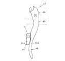
[実施例5]
次に、図17を参照して、本発明の第5実施例にかかる、変形例としてのブレーキ制御装置512Rを説明する。制御装置512Rが変形例としてのブレーキ制御レバー532を有していることを除いて、第5実施例は第1実施例と同一である。第1実施例と第5実施例との類似点を考慮して、第1実施例の部材と同一である第5実施例の部材には、第1実施例の部材と同じ参照符号を付している。また、説明の簡略化のために、第1実施例の部材と同一の第5実施例の部材の説明は省略する。しかしながら、ここに説明および例示された部分を除いて、第1実施例の説明および例示が第5実施例にも当てはまることは、本開示から当業者に明らかであろう。
[Example 5]
Next, referring to FIG. 17, a modified
詳細には、変形例としてのブレーキ制御レバー532は、基本的に、変形例としての基端部544と、その基端部に対して傾斜している変形例としての末端部546と、を備える。第1実施例の中間部48は、第5実施例においては取り除かれている。本実施例において、末端部546は、基端部544の長手方向長さとほぼ同じである。基端部544の長さ以外、基端部544は第1実施例と同一である。同様に、末端部は、より短くなっておりかつ傾斜しているが、第1実施例とほぼ同一である。この配置により、末端部546の横方向に最も外側の末端側端面546aは、ブレーキ面Pに対する垂直な方向において、ブレーキレバーブラケット30の横方向に最も外側のブラケット面上に実質的に位置している。また、この配置により、末端部546はブレーキ面Pに対して傾斜した末端中心長手方向軸X3を有しており、ブレーキ制御レバー532がレスト位置からブレーキ位置に移動するとき、末端中心長手方向軸X3は、ブレーキ面Pに対して傾斜した状態で移動する。
Specifically, the modified
[実施例6]
次に、図18を参照して、本発明の第6実施例にかかる、変形例としてのブレーキ制御装置612Rを説明する。制御装置512Rが変形例としてのブレーキレバーブラケット630を有することを除いて、第6実施例は第1実施例と同一である。第1実施例と第6実施例との類似点を考慮して、第1実施例の部材と同一である第6実施例の部材には、第1実施例の部材と同じ参照符号を付している。また、説明の簡略化のために、第1実施例の部材と同一の第6実施例の部材の説明は省略する。しかしながら、ここに説明および例示された部分を除いて、第1実施例の説明および例示が第6実施例にも当てはまることは、本開示から当業者に明らかであろう。
[Example 6]
Next, referring to FIG. 18, a modified
第2実施例における変形例としてのブレーキレバーブラケット630は、外側の面630bの横方向の最も外側の端面とブレーキ制御レバー32の最も外側の末端側端面46aとがほぼ同一面上に位置するように形成されている。本実施例において、ブレーキレバーブラケット630の外形は、外側の面630bの横方向に最も外側の端面とハンドルバー14の装着部14bの最も外側の端面とがほぼ同一面上に位置するように変形されている(つまり、狭くなっている)。なお、第1実施例におけるブレーキレバーブラケット30の内部構造を、その外部形状に変えて(例えば、この第6実施例のように変えて)、ブレーキコントロールレバー32が実質的にブレーキレバーブラケットの最外面に並ぶように第1実施例に示されている位置から横方向外側に取り付けられる如く、変更できるということは本開示から当業者に明らかであろう。
In the
ここで使用した「前方、後方、上方、上、下方、垂直、水平、下、横」などの方向を示す用語、ならびに他の同様の方向を表す用語は、本発明が装着された自転車の方向を示す用語として用いられている。したがって、本発明を説明するこれらの用語は、本発明の装着された自転車を基準に解釈されなければならない。 As used herein, terms indicating directions such as “front, back, up, up, down, vertical, horizontal, down, side”, as well as other similar directions are directions of the bicycle to which the present invention is attached. Is used as a terminology. Accordingly, these terms describing the present invention should be construed with reference to the mounted bicycle of the present invention.
本発明の範囲も理解において、ここで用いられる用語「備える」およびその派生語は、記載された特徴、エレメント、部品、群、完全体、および/またはステップがあることを明記しているオープンエンドの用語を意味するのであって、記載されていない特徴、エレメント、部品、群、完全体、および/またはステップがあることを排除するものではない。上記は、用語「有する」、「含む」およびそれらの派生語など同様の意味を持つ語にも当てはまる。また、単数形的に用いられる用語「部材」あるいは「エレメント」は、単一のパートあるいは複数のパーツの2つの意味を持ちうる。さらには、ここで使用されている「ほぼ」、「約」、「おおよそ」などの程度を表す用語は、最終結果が著しく変化しない妥当量の変化を意味する修正用語である。これらの用語は、修正対象の用語の意味を無効にしない範囲で、±5%の偏差を含むものと解釈される。 For purposes of understanding the scope of the present invention, the term “comprising” and its derivatives as used herein are open ends specifying that there is a stated feature, element, part, group, completeness, and / or step. And does not exclude the presence of features, elements, parts, groups, complete bodies, and / or steps not described. The above also applies to words having similar meanings such as the terms “having”, “including” and their derivatives. Further, the terms “member” or “element” used singularly may have two meanings: a single part or a plurality of parts. Furthermore, as used herein, terms such as “approximately”, “about”, “approximately”, etc. are amended terms that mean a reasonable amount of change that does not significantly change the final result. These terms are interpreted to include a deviation of ± 5% within a range that does not invalidate the meaning of the terms to be corrected.
本発明の説明のためにいくつかの実施例が選択されたに過ぎず、添付の特許請求の範囲に記載された本発明の範囲を逸脱することがない範囲で、様々な修正、変更を加えることができるということは、本開示から当業者には明らかである。さらに、前述の本発明にかかる実施例の説明は単なる例示であって、添付の特許請求の範囲およびそれらの均等物によって規定される発明を制限するものではないということは、本開示から当業者には明らかである。 Only a few embodiments have been selected to describe the present invention, and various modifications and changes are made without departing from the scope of the present invention as set forth in the appended claims. It will be apparent to those skilled in the art from this disclosure. Furthermore, it should be understood by those skilled in the art from this disclosure that the foregoing description of the embodiments of the invention is merely illustrative and is not intended to limit the invention as defined by the appended claims and their equivalents. Is obvious.
10 自転車
12R,12L ブレーキ制御装置
14 ハンドルバー
16 リアディレーラ
18 リアブレーキ装置
18a ブレーキケーブル
20 フロントディレーラ
22 フロントブレーキ装置
22a ブレーキケーブル
24 サイクルコンピュータ
30 ブレーキレバーブラケット
32 ブレーキ制御レバー
36 電気操作部材
36a 装着部
36b ライダー操作部
36c 電気接点部
40 グリップ体
44 基端部
46 末端部
48 中間部
50 ネジ
52 電気スイッチ用ハウジング
212R ブレーキ制御装置
230 ブレーキレバーブラケット
332 ブレーキ制御レバー
344 基端部
346 末端部
348 中間部
432 ブレーキ制御レバー
444 基端部
446 末端部
448 中間部
512R ブレーキ制御装置
532 ブレーキ制御レバー
544 基端部
546 末端部
612R ブレーキ制御装置
630 ブレーキレバーブラケット
S 電気スイッチ
C ハンドルバー中心線
P ブレーキ操作面
DESCRIPTION OF
Claims (31)
前記ブレーキレバーブラケットに回動可能に連結され、ブレーキ面に沿ってレスト位置からブレーキ位置へと前記ハンドルバーに向けてピボット軸回りに移動し、前記ブレーキレバーブラケットに回動自在に連結される基端部と前記基端部から延びる末端部とを有するブレーキ制御レバーと、
前記ブレーキ制御レバーの前記末端部に移動可能に連結され、電気的に自転車部品を動作させる電気操作部材と、
を備え、
前記ブレーキ制御レバーの前記末端部は、前記ブレーキ面に対する垂直な方向において前記基端部の横方向の最も外側の基端側端面から横方向外側に位置する横方向の最も外側の末端側端面を有しており、前記操作部材のライダー操作部は、前記ブレーキ制御レバーが前記ブレーキ位置に位置するときに前記ブレーキ面に対する垂直な方向において前記装着部のハンドルバー中心線から横方向外側に位置している、
自転車用ブレーキ制御装置。 A brake lever bracket to be mounted on the mounting portion of the bicycle handlebar;
A base that is pivotally connected to the brake lever bracket, moves about the pivot axis from the rest position to the brake position along the brake surface toward the handlebar, and is pivotally connected to the brake lever bracket. A brake control lever having an end and a distal end extending from the proximal end;
An electric operation member that is movably connected to the end portion of the brake control lever and electrically operates a bicycle component;
With
The distal end portion of the brake control lever is a laterally outermost distal end surface located laterally outward from the laterally outermost proximal end surface of the proximal end portion in a direction perpendicular to the brake surface. And the rider operating portion of the operating member is positioned laterally outward from the handlebar center line of the mounting portion in a direction perpendicular to the brake surface when the brake control lever is positioned at the brake position. ing,
Bicycle brake control device.
請求項1に記載の自転車用ブレーキ制御装置。 The outermost end surface of the end portion is not located laterally outward from the outermost bracket surface in the lateral direction of the brake lever bracket in a direction perpendicular to the brake surface;
The bicycle brake control device according to claim 1.
請求項2に記載の自転車用ブレーキ制御装置。 The outermost distal end surface of the distal portion is substantially located on the laterally outermost bracket surface of the brake lever bracket in a direction perpendicular to the brake surface;
The bicycle brake control device according to claim 2.
請求項1から3のいずれかに記載の自転車用ブレーキ制御装置。 The proximal end extends substantially linearly along the brake surface;
The bicycle brake control device according to any one of claims 1 to 3.
請求項1から4のいずれかに記載の自転車用ブレーキ制御装置。 The distal portion extends substantially linearly in a direction away from the proximal end portion,
The bicycle brake control device according to any one of claims 1 to 4.
請求項5に記載の自転車用ブレーキ制御装置。 The brake control lever includes an intermediate portion that is disposed between the distal end portion and the proximal end portion and is formed to position the distal end portion laterally outward from the proximal end portion.
The bicycle brake control device according to claim 5.
請求項6に記載の自転車用ブレーキ制御装置。 The intermediate portion is curved so that the distal portion is substantially parallel to the proximal portion and the distal portion is offset from the proximal portion;
The bicycle brake control device according to claim 6.
請求項5に記載の自転車用ブレーキ制御装置。 The distal end is inclined with respect to the proximal end;
The bicycle brake control device according to claim 5.
請求項8に記載の自転車用ブレーキ制御装置。 The outermost distal end surface of the distal portion is substantially located on the laterally outermost bracket surface of the brake lever bracket in a direction perpendicular to the brake surface;
The bicycle brake control device according to claim 8.
請求項1から9のいずれかに記載の自転車用ブレーキ制御装置。 The proximal end has a proximal central longitudinal axis that moves along the brake surface, and the brake surface substantially coincides with the center line of the mounting portion of the handlebar. ,
The bicycle brake control device according to any one of claims 1 to 9.
請求項1から10のいずれかに記載の自転車用ブレーキ制御装置。 The base end and the end of the brake control lever are integrally formed as a one-piece single material.
The bicycle brake control device according to any one of claims 1 to 10.
請求項1から11のいずれかに記載の自転車用ブレーキ制御装置。 The distal portion extends substantially linearly in a direction away from the proximal end portion,
The bicycle brake control device according to any one of claims 1 to 11.
請求項12に記載の自転車用ブレーキ制御装置。 The brake surface is perpendicular to the pivot axis and substantially includes a proximal central longitudinal axis of the proximal end;
The bicycle brake control device according to claim 12.
請求項13に記載の自転車用ブレーキ制御装置。 The distal end has a distal central longitudinal axis that moves along a plane that is substantially parallel to and offset from the brake surface when the brake control lever moves from the rest position to the brake position. ,
The bicycle brake control device according to claim 13.
請求項13に記載の自転車用ブレーキ制御装置。 The end portion has an end center longitudinal axis that is inclined with respect to the brake surface, the end center longitudinal axis being when the brake control lever moves from the rest position to the brake position. To move in an inclined state with respect to the brake surface,
The bicycle brake control device according to claim 13.
請求項1から15のいずれかに記載の自転車用ブレーキ制御装置。 The brake control lever includes an intermediate portion that is disposed between the distal end portion and the proximal end portion and is formed to position the distal end portion laterally outward from the proximal end portion.
The bicycle brake control device according to any one of claims 1 to 15.
請求項16に記載の自転車用ブレーキ制御装置。 A majority of the proximal end is disposed within the brake lever bracket;
The bicycle brake control device according to claim 16.
請求項17に記載の自転車用ブレーキ制御装置。 A majority of the intermediate portion is disposed within the brake lever bracket;
The bicycle brake control device according to claim 17.
請求項16から18のいずれかに記載の自転車用ブレーキ制御装置。 The intermediate portion has a longitudinal length shorter than the longitudinal length of the end portion,
The bicycle brake control device according to any one of claims 16 to 18.
請求項19に記載の自転車用ブレーキ制御装置。 The longitudinal length of the intermediate portion is shorter than the longitudinal length of the proximal end portion,
The bicycle brake control device according to claim 19.
請求項16から18のいずれかに記載の自転車用ブレーキ制御装置。 The intermediate portion has a longitudinal length shorter than the longitudinal length of the proximal end portion,
The bicycle brake control device according to any one of claims 16 to 18.
請求項16から21のいずれかに記載の自転車用ブレーキ制御装置。 The base end portion, the distal end portion, and the intermediate portion of the brake control lever are integrally formed as a one-piece single material,
The bicycle brake control device according to any one of claims 16 to 21.
請求項1から22のいずれかに記載の自転車用ブレーキ制御装置。 A majority of the proximal end is disposed within the brake lever bracket;
The bicycle brake control device according to any one of claims 1 to 22.
請求項1から23のいずれかに記載の自転車用ブレーキ制御装置。 The rider operation portion of the electric operation member is between the handlebar center line of the mounting portion of the handlebar and a laterally outermost bracket surface of the brake lever bracket in a direction perpendicular to the brake surface. Located in the
The bicycle brake control device according to any one of claims 1 to 23.
請求項1から24のいずれかに記載の自転車用ブレーキ制御装置。 Most of the rider operation portion of the electric operation member is configured such that when the brake control lever moves from the rest position to the brake position, the handlebar center line of the mounting portion of the handlebar and the handlebar It is located between the laterally outermost handlebar surface of the mounting portion,
The bicycle brake control device according to any one of claims 1 to 24.
請求項1から25のいずれかに記載の自転車用ブレーキ制御装置。 The distal end has a longitudinal length that is longer than the longitudinal length of the proximal end.
The bicycle brake control device according to any one of claims 1 to 25.
請求項1から25のいずれかに記載の自転車用ブレーキ制御装置。 The distal portion has a longitudinal length that is shorter than the longitudinal length of the proximal portion,
The bicycle brake control device according to any one of claims 1 to 25.
請求項1から25のいずれかに記載の自転車用ブレーキ制御装置。 The distal end has a longitudinal length that is substantially the same as the longitudinal length of the proximal end;
The bicycle brake control device according to any one of claims 1 to 25.
請求項1から28のいずれかに記載の自転車用ブレーキ制御装置。 The electric operation member is a part of an electric shift control switch.
The bicycle brake control device according to any one of claims 1 to 28.
請求項1から29のいずれかに記載の自転車用ブレーキ制御装置。 The electric operation member is rotatable relative to the brake control lever;
The bicycle brake control device according to any one of claims 1 to 29.
請求項1から30のいずれかに記載の自転車用ブレーキ制御装置。 The brake lever bracket has a tubular clamp part, and the tubular clamp part is fixedly attached to the attachment part of the handlebar so as to be immovable.
The bicycle brake control device according to any one of claims 1 to 30.
Applications Claiming Priority (1)
| Application Number | Priority Date | Filing Date | Title |
|---|---|---|---|
| US10/953,458 US20060070480A1 (en) | 2004-09-30 | 2004-09-30 | Bicycle brake control device with electrical operating member |
Publications (1)
| Publication Number | Publication Date |
|---|---|
| JP2006103674A true JP2006103674A (en) | 2006-04-20 |
Family
ID=35160064
Family Applications (1)
| Application Number | Title | Priority Date | Filing Date |
|---|---|---|---|
| JP2005277971A Withdrawn JP2006103674A (en) | 2004-09-30 | 2005-09-26 | Brake control device for bicycle with electric operation member |
Country Status (6)
| Country | Link |
|---|---|
| US (1) | US20060070480A1 (en) |
| EP (1) | EP1642823B1 (en) |
| JP (1) | JP2006103674A (en) |
| CN (1) | CN1754768A (en) |
| BR (1) | BRPI0503786A (en) |
| TW (1) | TWI260294B (en) |
Cited By (1)
| Publication number | Priority date | Publication date | Assignee | Title |
|---|---|---|---|---|
| JP2009126515A (en) * | 2007-11-23 | 2009-06-11 | Campagnolo Spa | Control device for bicycle with curved handlebar |
Families Citing this family (19)
| Publication number | Priority date | Publication date | Assignee | Title |
|---|---|---|---|---|
| ITTO20011079A1 (en) * | 2001-11-16 | 2003-05-16 | Campagnolo Srl | ,, GEARBOX CONTROL DEVICE FOR A BICYCLE WITH A HANDLEBAR WITH STRAIGHT ENDS ,, |
| EP1564131B1 (en) | 2004-02-06 | 2007-08-15 | Campagnolo S.R.L. | Actuation device for a control cable for a bicycle gearshift |
| ATE520583T1 (en) | 2005-06-27 | 2011-09-15 | Campagnolo Srl | CONTROL DEVICE FOR A BICYCLE CHAIN GEARS |
| ATE477997T1 (en) * | 2006-01-23 | 2010-09-15 | Campagnolo Srl | CONTROL DEVICE FOR BICYCLE CHAIN GEARS |
| DE602006015158D1 (en) * | 2006-02-23 | 2010-08-12 | Campagnolo Srl | Bicycle brake control device |
| ITMI20070239A1 (en) | 2007-02-09 | 2008-08-10 | Campagnolo Srl | CONTROL DEVICE FOR A BICYCLE DERAILLEUR |
| ITMI20070400A1 (en) | 2007-03-01 | 2008-09-02 | Campagnolo Srl | COMMAND DEVICE FOR BICYCLE AND BICYCLE INCLUDING SUCH DIPSOSITIVE |
| ITMI20070399A1 (en) | 2007-03-01 | 2008-09-02 | Campagnolo Srl | COMMAND DEVICE FOR BICYCLE AND BICYCLE THAT INCLUDES IT |
| ITMI20070401A1 (en) * | 2007-03-01 | 2008-09-02 | Campagnolo Srl | CONTROL DEVICE FOR BICYCLE AND BICYCLE INCLUDING THIS DEVICE |
| ITMI20070398A1 (en) | 2007-03-01 | 2008-09-02 | Campagnolo Srl | COMMAND DEVICE FOR BICYCLE AND BICYCLE THAT INCLUDES IT |
| US8393244B2 (en) | 2007-08-06 | 2013-03-12 | Shimano Inc. | Bicycle operating device |
| US9016162B2 (en) * | 2008-06-30 | 2015-04-28 | Shimano Inc. | Bicycle component operating device |
| US8177078B2 (en) * | 2009-06-03 | 2012-05-15 | Michael Pezzati | Eyeglasses retainer for handle bars |
| TW201427863A (en) * | 2013-01-10 | 2014-07-16 | Ad Ii Engineering Inc | Electrical shift controller and bike handlebar using the same |
| CN103963916B (en) * | 2013-01-24 | 2017-09-29 | 台湾微转股份有限公司 | Electrical shift control device and the bicycle handle using the device |
| US9434444B2 (en) * | 2013-11-08 | 2016-09-06 | Shimano Inc. | Bicycle hydraulic actuating device |
| US20150284049A1 (en) * | 2014-04-04 | 2015-10-08 | Sram, Llc | Control assembly for a wireless electromechanical bicycle shifting system |
| US10894578B2 (en) | 2018-01-11 | 2021-01-19 | Sram, Llc | Electronic shift control device for a bicycle derailleur |
| US11390353B2 (en) * | 2020-05-01 | 2022-07-19 | Shimano Inc. | Operating device for human-powered vehicle |
Family Cites Families (12)
| Publication number | Priority date | Publication date | Assignee | Title |
|---|---|---|---|---|
| JPS58186990U (en) * | 1982-06-09 | 1983-12-12 | 株式会社シマノ | Bicycle control device |
| JPH02120299U (en) * | 1989-03-16 | 1990-09-27 | ||
| US5159851A (en) * | 1991-09-18 | 1992-11-03 | Paul Rahmes | Bicycle grip |
| IT1261090B (en) * | 1993-07-08 | 1996-05-08 | Antonio Romano | MOTORIZED SPEED CHANGE UNIT FOR BICYCLES. |
| JP3510442B2 (en) * | 1997-01-14 | 2004-03-29 | 株式会社シマノ | Bicycle electric shifting mechanism |
| IT1320405B1 (en) * | 2000-06-06 | 2003-11-26 | Campagnolo Srl | ELECTRIC CONTROL DEVICE FOR A MOTORIZED FRONT DERAILLEUR. |
| US20010053274A1 (en) * | 2000-06-20 | 2001-12-20 | Koninklijke Philips Electronics N.V. | System and method for remote control of consumer electronics over data network with visual feedback |
| US6546827B2 (en) * | 2001-03-28 | 2003-04-15 | Shimano Inc. | Bicycle handlebar |
| ITTO20010555A1 (en) * | 2001-06-08 | 2002-12-08 | Campagnolo Srl | ELECTRIC CONTROL DEVICE FOR A MOTORIZED FRONT DERAILLEUR FOR BICYCLES. |
| US6698307B2 (en) * | 2001-10-23 | 2004-03-02 | Sram Corporation | Electronic shifter for a bicycle |
| US6991081B2 (en) | 2003-11-26 | 2006-01-31 | Shimano Inc. | Shift and break control device |
| US7174805B2 (en) * | 2004-04-30 | 2007-02-13 | Tektro Technology Corporation | Cross racing bike front brake lever |
-
2004
- 2004-09-30 US US10/953,458 patent/US20060070480A1/en not_active Abandoned
-
2005
- 2005-05-12 TW TW094115410A patent/TWI260294B/en not_active IP Right Cessation
- 2005-05-25 CN CN200510072069.6A patent/CN1754768A/en active Pending
- 2005-08-10 EP EP05017423A patent/EP1642823B1/en not_active Revoked
- 2005-08-31 BR BRPI0503786-7A patent/BRPI0503786A/en not_active IP Right Cessation
- 2005-09-26 JP JP2005277971A patent/JP2006103674A/en not_active Withdrawn
Cited By (2)
| Publication number | Priority date | Publication date | Assignee | Title |
|---|---|---|---|---|
| JP2009126515A (en) * | 2007-11-23 | 2009-06-11 | Campagnolo Spa | Control device for bicycle with curved handlebar |
| US9126650B2 (en) | 2007-11-23 | 2015-09-08 | Campagnolo S.R.L. | Control device for a bicycle with curved handlebars |
Also Published As
| Publication number | Publication date |
|---|---|
| US20060070480A1 (en) | 2006-04-06 |
| TWI260294B (en) | 2006-08-21 |
| CN1754768A (en) | 2006-04-05 |
| EP1642823A2 (en) | 2006-04-05 |
| TW200610698A (en) | 2006-04-01 |
| BRPI0503786A (en) | 2006-05-09 |
| EP1642823B1 (en) | 2012-01-25 |
| EP1642823A3 (en) | 2007-11-21 |
Similar Documents
| Publication | Publication Date | Title |
|---|---|---|
| JP2006103674A (en) | Brake control device for bicycle with electric operation member | |
| US6991081B2 (en) | Shift and break control device | |
| US8393244B2 (en) | Bicycle operating device | |
| US9199688B2 (en) | Bicycle control device | |
| US7228756B2 (en) | Bicycle control device | |
| TWI331112B (en) | ||
| US7565848B2 (en) | Bicycle control device | |
| US8297143B2 (en) | Electrical bicycle shift control device | |
| US7841255B2 (en) | Electrical bicycle shift control device | |
| TWI299312B (en) | Bicycle control device | |
| US7100471B2 (en) | Bicycle control device | |
| EP2082953B1 (en) | Bicycle control device | |
| US20070193388A1 (en) | Bicycle shift control device | |
| US20070137361A1 (en) | Bicycle operating component with electrical shift control switch | |
| EP1473220A1 (en) | Control device for a bicycle derailleur | |
| US20080098848A1 (en) | Control device for a bicycle and related kit of parts | |
| EP1816062A2 (en) | Bicycle shift control device | |
| US20100083786A1 (en) | Bicycle component body assembly | |
| EP2065298A1 (en) | Bicycle control device | |
| US20150296907A1 (en) | Bicycle Handlebar and COntrol System | |
| EP1452433B1 (en) | Twist grip for operating a bicycle transmission | |
| TWI586576B (en) | Operating device | |
| JPH10147277A (en) | Brake lever and bar end for bicycle |
Legal Events
| Date | Code | Title | Description |
|---|---|---|---|
| A761 | Written withdrawal of application |
Free format text: JAPANESE INTERMEDIATE CODE: A761 Effective date: 20080218 |