JP7033056B2 - Color prediction model construction method, color prediction method, and color prediction model construction program - Google Patents
Color prediction model construction method, color prediction method, and color prediction model construction program Download PDFInfo
- Publication number
- JP7033056B2 JP7033056B2 JP2018240741A JP2018240741A JP7033056B2 JP 7033056 B2 JP7033056 B2 JP 7033056B2 JP 2018240741 A JP2018240741 A JP 2018240741A JP 2018240741 A JP2018240741 A JP 2018240741A JP 7033056 B2 JP7033056 B2 JP 7033056B2
- Authority
- JP
- Japan
- Prior art keywords
- color
- patch
- color prediction
- spectral
- ink
- Prior art date
- Legal status (The legal status is an assumption and is not a legal conclusion. Google has not performed a legal analysis and makes no representation as to the accuracy of the status listed.)
- Active
Links
Images


Classifications
-
- H—ELECTRICITY
- H04—ELECTRIC COMMUNICATION TECHNIQUE
- H04N—PICTORIAL COMMUNICATION, e.g. TELEVISION
- H04N1/00—Scanning, transmission or reproduction of documents or the like, e.g. facsimile transmission; Details thereof
- H04N1/46—Colour picture communication systems
- H04N1/56—Processing of colour picture signals
- H04N1/60—Colour correction or control
- H04N1/603—Colour correction or control controlled by characteristics of the picture signal generator or the picture reproducer
- H04N1/6033—Colour correction or control controlled by characteristics of the picture signal generator or the picture reproducer using test pattern analysis
Description
本発明は、複数の色(典型的には、特色を含む複数の色)のインクの重ね刷りによって得られる色を予測する際に用いられるカラーチャート内のパッチの色を予測するための色予測モデルを構築する方法および当該色予測モデルを用いた色予測方法に関する。 The present invention is a color prediction for predicting the color of a patch in a color chart used when predicting the color obtained by overprinting inks of a plurality of colors (typically, a plurality of colors including spot colors). The present invention relates to a method of constructing a model and a color prediction method using the color prediction model.
近年、印刷業界では、デジタル印刷装置の普及が進んでいる。しかしながら、ラベル・パッケージの分野では、近年でも印刷版を使用した印刷装置(以下、「従来方式の印刷装置」あるいは単に「印刷装置」という。)による印刷(オフセット印刷、グラビア印刷、フレキソ印刷など)が行われることが多い。ところが、デザインやコンテンツの制作の短納期化の要求が高まっており、従来方式の印刷装置を使用している場合にはデザイン等の変更があったときに印刷版の再作製や工程の後戻りによって生じるコストが大きいことが問題となっている。この点、デジタル印刷装置によれば、印刷版を使用しないため、印刷版の交換・再作製という作業が発生することがない。すなわち、デジタル印刷装置を採用することにより、特に小ロットの印刷を低コストで行うことが可能となり、デザインやコンテンツの制作の短納期化の要求へも低コストで対応することが可能となる。 In recent years, digital printing devices have become widespread in the printing industry. However, in the field of label packaging, even in recent years, printing by a printing device using a printing plate (hereinafter referred to as "conventional printing device" or simply "printing device") (offset printing, gravure printing, flexo printing, etc.) Is often done. However, there is an increasing demand for shorter delivery times for design and content production, and when using conventional printing equipment, when there is a change in design, etc., the printing plate is remade or the process goes back. The problem is that the costs involved are high. In this respect, according to the digital printing apparatus, since the printing plate is not used, the work of exchanging / remanufacturing the printing plate does not occur. That is, by adopting a digital printing device, it is possible to print a small lot at low cost, and it is possible to meet the demand for short delivery time for design and content production at low cost.
ところで、ラベル・パッケージの分野では、色の表現力を高めるために特色が多用される傾向にある。このため、従来方式の印刷装置での印刷用に生成された印刷データを用いてデジタル印刷装置で印刷を行うためには、特色のインクの重ね刷りによって得られる色の予測を行って、その予測した色をデジタル印刷装置で再現する必要がある。なお、以下においては、複数の色のインクの重ね刷りによって得られる色を特定する値(具体的には、反射率、あるいは、CIE1931XYZ色空間における三刺激値X,Y,およびZ)の予測値のことを「オーバープリント予測値」という。 By the way, in the field of labels and packages, spot colors tend to be frequently used in order to enhance the expressiveness of colors. Therefore, in order to print with a digital printing device using the print data generated for printing with a conventional printing device, the color obtained by overprinting the special color ink is predicted and the prediction is performed. It is necessary to reproduce the printed colors on a digital printing device. In the following, the predicted values of the values that specify the color obtained by overprinting the inks of a plurality of colors (specifically, the reflectance or the tristimulation values X, Y, and Z in the CIE1931XYZ color space). This is called "overprint predicted value".
後述する非特許文献1には、特色を含む複数の色のインクの重ね刷りによって得られる色(オーバープリント予測値)を比較的簡単に予測する手法(以下、「Deshpandeらの手法」という。)が開示されている。Deshpandeらの手法では、オーバープリント予測値は、三刺激値X,Y,およびZを用いて次式(1)~(3)のように表される(図20参照)。
X=jx×(Xb×Xf)+kx ・・・(1)
Y=jy×(Yb×Yf)+ky ・・・(2)
Z=jz×(Zb×Zf)+kz ・・・(3)
ここで、Xb,Yb,およびZbは背景色の三刺激値であり、Xf,Yf,およびZfは前景色の三刺激値であり、jx,jy,およびjzはスケーリング係数であり、kx,ky,およびkzは定数である。以下、jx,jy,jz,kx,ky,およびkzをまとめて「オーバープリント係数」という。
In
X = j x × (X b × X f ) + k x ... (1)
Y = j y x (Y b x Y f ) + k y ... (2)
Z = j z × (Z b × Z f ) + k z ... (3)
Here, X b , Y b , and Z b are the tristimulation values of the background color, and X f , Y f , and Z f are the tristimulation values of the foreground color, and j x , j y , and j z . Is the scaling factor and k x , ky, and k z are constants. Hereinafter, j x , j y , j z , k x , ky , and k z are collectively referred to as "overprint coefficient".
ところで、色の再現方法には加法混色と減法混色とがあるが、印刷の場合には減法混色によって色の再現が行われる。これに関し、仮に理想的な減法混色が行われると、例えば、重ね刷りによって得られる色の刺激値Xは「Xb×Xf」で表される(刺激値Y,Zについても同様である)。しかしながら、より正確な値を得るためには、不透明インクの使用や表面での光の反射などに起因する誤差を考慮した補正が必要となる。そこで、Deshpandeらの手法では、上式(1)~(3)に示したように、一次式を用いた補正が行われている。 By the way, there are additive color mixing and subtractive color mixing as color reproduction methods, but in the case of printing, color reproduction is performed by subtractive color mixing. In this regard, if ideal subtractive color mixing is performed, for example, the stimulus value X of the color obtained by overprinting is represented by "X b x X f " (the same applies to the stimulus values Y and Z). .. However, in order to obtain a more accurate value, it is necessary to make a correction in consideration of an error caused by the use of opaque ink, reflection of light on the surface, and the like. Therefore, in the method of Deshpade et al., As shown in the above equations (1) to (3), the correction using the linear equation is performed.
Deshpandeらの手法では、例えば、模式的には図21に示すようなカラーチャートが使用される。このカラーチャートは「CxFチャート」と呼ばれている。図21に示す例では、CxFチャートは22個のパッチによって構成されている。上段の11個のパッチは、網点パーセントを10%刻みにして対象の特色のインクを紙などの基材上に印刷することによって得られるパッチである。下段の11個のパッチは、網点パーセントを10%刻みにして対象の特色のインクを黒色(墨ベタ)上に印刷することによって得られるパッチである。このようなCxFチャートのパッチの測色で得られる値(測色値)を用いて、オーバープリント予測値が算出される。 In the method of Deshpanda et al., For example, a color chart as shown in FIG. 21 is schematically used. This color chart is called a "CxF chart". In the example shown in FIG. 21, the CxF chart is composed of 22 patches. The 11 patches in the upper row are patches obtained by printing the ink of the target special color on a substrate such as paper in increments of 10% halftone dots. The lower 11 patches are patches obtained by printing the target color ink on black (black solid) with halftone dot percentages in 10% increments. The overprint prediction value is calculated using the value (color measurement value) obtained by the color measurement of the patch of the CxF chart.
以下、図22に示すフローチャートを参照しつつ、背景色が網点パーセントを40%とする特色(便宜上「特色1」という。)であって前景色が網点パーセントを60%とする別の特色(便宜上「特色2」という。)である場合のオーバープリント予測値の算出を例に挙げて、Deshpandeらの手法について詳しく説明する。
Hereinafter, while referring to the flowchart shown in FIG. 22, another spot color in which the background color has a halftone dot percentage of 40% (referred to as “
まず、特色1のインクを用いてCxFチャートの印刷が行われ、さらに、特色2のインクを用いてCxFチャートの印刷が行われる(ステップS900)。
First, the CxF chart is printed using the ink of the
次に、特色2のインクを用いて印刷されたCxFチャート(便宜上「特色2チャート」という。)を使用して、特色2に関する上式(1)~(3)のオーバープリント係数jx,jy,jz,kx,ky,およびkzが算出される(ステップS910)。これに関し、例えば、上式(1)に着目すると、Xb×Xfについての実用上の最大値および最小値は、それぞれ、基材上および黒色(墨ベタ)上に特色2のインクが塗られたことによって得られる値である。Yb×YfおよびZb×Zfについても同様である。そこで、オーバープリント係数を算出するために、上式(1)~(3)を表す座標系(図23参照:但し、図23には上式(1)を表す座標系のみを示している。)において、黒色上に網点パーセントを60%とする特色2のインクが塗られた状態の刺激値を表す座標が第1校正点P91とされ、基材上に網点パーセントを60%とする特色2のインクが塗られた状態の刺激値を表す座標が第2校正点P92とされる。
Next, using a CxF chart printed using the ink of the spot color 2 (referred to as a “
三刺激値のうちの例えばXに着目すると、第1校正点P91については、上式(1)に対して次のように値の代入が行われる。特色2チャートのパッチPA93の測色によって得られる値(黒色の刺激値)がXbに代入され、特色2チャートのパッチPA92の測色によって得られる値(基材上に網点パーセントを60%とする特色2のインクが塗られた状態の刺激値)がXfに代入され、特色2チャートのパッチPA91の測色によって得られる値(黒色上に網点パーセントを60%とする特色2のインクが塗られた状態の刺激値)がXに代入される(図21参照)。また、第2校正点P92については、上式(1)に対して次のように値の代入が行われる。特色2チャートのパッチPA94の測色によって得られる値(基材の刺激値)がXbに代入され、特色2チャートのパッチPA92の測色によって得られる値(基材上に網点パーセントを60%とする特色2のインクが塗られた状態の刺激値)がXfおよびXに代入される(図21参照)。
Focusing on, for example, X among the three stimulus values, the value is substituted for the first calibration point P91 with respect to the above equation (1) as follows. The value obtained by the color measurement of the patch PA93 of the
第1校正点P91に関する方程式と第2校正点P92に関する方程式との連立方程式を解くことによってオーバープリント係数jx,kxが算出される。すなわち、図23で符号L91を付した直線を表す式が得られる。オーバープリント係数jy,jz,ky,およびkzについても、同様にして算出される。 The overprint coefficients j x and k x are calculated by solving the simultaneous equations of the equation relating to the first calibration point P91 and the equation relating to the second calibration point P92. That is, an equation representing a straight line with reference numeral L91 is obtained in FIG. 23. The overprint coefficients j y , j z , ky, and k z are calculated in the same manner.
なお、図21に示すCxFチャートでは10%刻みでパッチが設けられているが、線形補間によって得られる測色値に基づいて、左右方向に隣接する2つのパッチ間の網点パーセントに対応するオーバープリント係数を求めることができる。 In the CxF chart shown in FIG. 21, patches are provided in increments of 10%, but based on the colorimetric value obtained by linear interpolation, an overtone corresponding to the halftone dot percentage between two patches adjacent in the left-right direction is over. The print coefficient can be obtained.
次に、特色1のインクを用いて印刷されたCxFチャート(便宜上「特色1チャート」という。)を使用して、最終的なオーバープリント予測値を算出するための上式(1)~(3)中のXb,Yb,およびZbの値(背景色の三刺激値)が取得される(ステップS920)。具体的には、特色1チャートのパッチPA95(図21参照)の測色によって、Xb,Yb,およびZbの値が取得される。
Next, the above equations (1) to (3) for calculating the final overprint prediction value using the CxF chart (referred to as “
次に、特色2チャートを使用して、最終的なオーバープリント予測値を算出するための上式(1)~(3)中のXf,Yf,およびZfの値(前景色の三刺激値)が取得される(ステップS930)。具体的には、特色2チャートのパッチPA92(図21参照)の測色によって、Xf,Yf,およびZfの値が取得される。
Next, using the
最後に、ステップS910~S930で得られた値を上式(1)~(3)に代入することによって、オーバープリント予測値としての三刺激値X,Y,およびZが算出される(ステップS940)。これは、例えば、図23で符号L91を付した直線において横軸が「ステップS920で取得されたXb」と「ステップS930で取得されたXf」との積であるときの縦軸の値をXの値として算出することに相当する。 Finally, by substituting the values obtained in steps S910 to S930 into the above equations (1) to (3), the tristimulation values X, Y, and Z as overprint predicted values are calculated (step S940). ). This is, for example, the value of the vertical axis when the horizontal axis is the product of "X b acquired in step S920" and "X f acquired in step S930" in the straight line with the reference numeral L91 in FIG. 23. Is equivalent to calculating as the value of X.
なお、上記では、特色2チャートのパッチPA91,PA92,およびPA93をそれぞれ測色することによって、第1校正点P91(図23参照)に関するX,Xf,およびXbの値を取得している。しかし、高精度のオーバープリント予測値が必要とされないのであれば、簡単のために第1校正点P91を図23のグラフの原点に位置するとみなすこともできる。この場合には、特色2チャートのパッチPA91およびPA93の測色が不要になる(第2校正点P92のXおよびXfの値の取得のためにパッチPA92の測色は依然として必要である)。この場合、図21に示すCxFチャートのパッチPA91およびPA93等を含む下段のパッチ群を印刷しなくても、オーバープリント予測値としての三刺激値X,Y,およびZを算出することができる。このように、図21に示す上段のパッチ群を有し下段のパッチ群を備えないCxFチャートを本明細書では便宜上「簡易CxFチャート」という。
In the above, the values of X, X f , and X b related to the first calibration point P91 (see FIG. 23) are acquired by measuring the colors of the patches PA91, PA92, and PA93 of the
なお、本発明に関連して、特開平6-281501号公報には、或る測色装置で得られた色彩値から他の測色装置で得られる色彩値をニューラルネットワークを用いて求める色彩値修正装置の発明が開示されている。 In connection with the present invention, Japanese Patent Application Laid-Open No. 6-281501 describes a color value obtained by using a neural network to obtain a color value obtained by another color measuring device from a color value obtained by one color measuring device. The invention of the modifying device is disclosed.
上述したように、Deshpandeらの手法によれば、例えば図21に示したようなCxFチャートを用いて色の予測が行われている。ところが、特色を用いた印刷が行われる場合であっても、通常、このようなCxFチャートは事前には印刷されていない。このため、特色の数に等しい数のCxFチャートを印刷して各パッチの測色を行う必要性が生じる。これにより、コストの増加や工数の増加が引き起こされる。 As described above, according to the method of Deshpade et al., Color prediction is performed using, for example, a CxF chart as shown in FIG. 21. However, even when printing using spot colors is performed, such a CxF chart is usually not printed in advance. Therefore, it becomes necessary to print a number of CxF charts equal to the number of spot colors to measure the color of each patch. This causes an increase in cost and man-hours.
そこで、本発明は、複数の色のインクの重ね刷りによって得られる色を従来よりも低コストかつ少ない工数で予測できるよう、CxFチャートに含まれるべきパッチの色の予測を可能にすることを目的とする。 Therefore, an object of the present invention is to make it possible to predict the color of a patch to be included in a CxF chart so that the color obtained by overprinting inks of a plurality of colors can be predicted at a lower cost and with less man-hours than before. And.
第1の発明は、基材上にインクを複数段階のインク濃度で塗ることによって得られる複数の第1タイプパッチを含むカラーチャート内のパッチの色を予測する色予測モデルを構築する方法であって、
前記カラーチャート内の所定のパッチである基準パッチの分光特性と前記カラーチャート内の色予測対象パッチの色値とを含む複数の教師データを取得する教師データ取得ステップと、
入力データを前記基準パッチの分光特性とし出力データを前記色予測対象パッチの色値とするニューラルネットワークで前記複数の教師データを用いた機械学習を行う学習ステップと
を含むことを特徴とする。
The first invention is a method of constructing a color prediction model for predicting the color of a patch in a color chart including a plurality of first type patches obtained by applying ink on a substrate at a plurality of stages of ink densities. hand,
A teacher data acquisition step for acquiring a plurality of teacher data including the spectral characteristics of a reference patch which is a predetermined patch in the color chart and the color value of the color prediction target patch in the color chart.
It is characterized by including a learning step of performing machine learning using the plurality of teacher data in a neural network in which the input data is the spectral characteristic of the reference patch and the output data is the color value of the color prediction target patch.
第2の発明は、第1の発明において、
前記基準パッチは、前記複数の第1タイプパッチのうちインク濃度が最大のパッチであることを特徴とする。
The second invention is the first invention.
The reference patch is characterized in that it is the patch having the highest ink density among the plurality of first type patches.
第3の発明は、第1の発明において、
前記基準パッチは、前記複数の第1タイプパッチのうちインク濃度が最大のパッチおよび前記複数の第1タイプパッチのうちインク濃度が最小のパッチであることを特徴とする。
The third invention is the first invention.
The reference patch is characterized in that it is a patch having the highest ink density among the plurality of first type patches and a patch having the lowest ink density among the plurality of first type patches.
第4の発明は、第1から第3までのいずれかの発明において、
前記色予測対象パッチは、N個のパッチであって、
前記N個のパッチと1対1で対応するようにN個の前記ニューラルネットワークが用意され、
前記学習ステップでは、ニューラルネットワーク毎に、対応するパッチの色値と前記基準パッチの分光特性とを用いて機械学習が行われることを特徴とする。
The fourth invention is the invention of any one of the first to the third.
The color prediction target patch is N patches.
N neural networks are prepared so as to have a one-to-one correspondence with the N patches.
The learning step is characterized in that machine learning is performed for each neural network using the color values of the corresponding patches and the spectral characteristics of the reference patch.
第5の発明は、第1から第3までのいずれかの発明において、
前記色予測対象パッチは、N個のパッチであって、
入力データを前記基準パッチの分光特性とし出力データを前記N個のパッチの色値とする1つだけの前記ニューラルネットワークが用意され、
前記学習ステップでは、前記1つだけのニューラルネットワークによって前記基準パッチの分光特性と前記N個のパッチの色値とを用いて機械学習が行われることを特徴とする。
The fifth invention is the invention of any one of the first to the third.
The color prediction target patch is N patches.
Only one neural network is prepared, in which the input data is the spectral characteristic of the reference patch and the output data is the color value of the N patches.
The learning step is characterized in that machine learning is performed by using only one neural network using the spectral characteristics of the reference patch and the color values of the N patches.
第6の発明は、第1から第5までのいずれかの発明において、
前記カラーチャート内の各パッチの色は、K個の分光特性によって特定され、
前記ニューラルネットワークは、入力層と隠れ層と出力層とを含み、
前記入力層には、前記基準パッチとしての1つのパッチにつきK個のユニットが設けられ、
前記出力層には、前記色予測対象パッチとしての1つのパッチにつきK個のユニットが設けられていることを特徴とする。
The sixth invention is the invention in any one of the first to fifth inventions.
The color of each patch in the color chart is identified by K spectral properties.
The neural network includes an input layer, a hidden layer, and an output layer.
The input layer is provided with K units for each patch as the reference patch.
The output layer is characterized in that K units are provided for one patch as the color prediction target patch.
第7の発明は、第6の発明において、
前記K個の分光特性は、400nmから700nmまでの波長範囲を適宜の大きさの単位波長範囲で除することによって得られる数の分光反射率であることを特徴とする。
The seventh invention is the sixth invention.
The K spectral characteristics are characterized by a number of spectral reflectances obtained by dividing a wavelength range from 400 nm to 700 nm by a unit wavelength range of an appropriate size.
第8の発明は、第1から第6までのいずれかの発明において、
前記分光特性は、分光反射率、分光吸収率、および分光吸収係数のいずれかであることを特徴とする。
The eighth invention is the invention in any one of the first to the sixth.
The spectral characteristic is one of a spectral reflectance, a spectral absorption rate, and a spectral absorption coefficient.
第9の発明は、第1から第8までのいずれかの発明において、
前記色値は分光特性であることを特徴とする。
The ninth invention is the invention of any one of the first to the eighth.
The color value is characterized by its spectral characteristics.
第10の発明は、第9の発明において、
前記教師データ取得ステップは、
各教師データを生成するための前記カラーチャートの印刷を行うカラーチャート印刷ステップと、
前記カラーチャート印刷ステップで印刷されたカラーチャートに関して前記基準パッチの分光特性および前記色予測対象パッチの分光特性を測定する第1の分光特性測定ステップと
を含むことを特徴とする。
The tenth invention is the ninth invention.
The teacher data acquisition step is
A color chart printing step for printing the color chart for generating each teacher data, and
It is characterized by including a first spectral characteristic measurement step for measuring the spectral characteristics of the reference patch and the spectral characteristics of the color prediction target patch with respect to the color chart printed in the color chart printing step.
第11の発明は、第1から第8までのいずれかの発明において、
前記色値は、階調レベルであることを特徴とする。
The eleventh invention is the invention of any one of the first to the eighth.
The color value is characterized by being a gradation level.
第12の発明は、第11の発明において、
前記教師データ取得ステップは、
各教師データを生成するための前記カラーチャートの印刷を行うカラーチャート印刷ステップと、
前記カラーチャート印刷ステップで印刷されたカラーチャートに関して前記基準パッチの分光特性および前記色予測対象パッチの分光特性を測定する第1の分光特性測定ステップと、
前記第1の分光特性測定ステップで測定された前記色予測対象パッチの分光特性を階調レベルに変換する色値変換ステップと
を含むことを特徴とする。
The twelfth invention is the eleventh invention.
The teacher data acquisition step is
A color chart printing step for printing the color chart for generating each teacher data, and
A first spectral characteristic measurement step for measuring the spectral characteristics of the reference patch and the spectral characteristics of the color prediction target patch with respect to the color chart printed in the color chart printing step.
It is characterized by including a color value conversion step of converting the spectral characteristics of the color prediction target patch measured in the first spectral characteristic measurement step into a gradation level.
第13の発明は、第1から第12までのいずれかの発明において、
前記カラーチャートは、黒色インク上に前記インクを前記複数段階のインク濃度で塗ることによって得られる複数の第2タイプパッチをさらに含むことを特徴とする。
The thirteenth invention is the invention in any one of the first to the twelfth.
The color chart is characterized by further comprising a plurality of second type patches obtained by applying the ink on the black ink at the plurality of stages of ink densities.
第14の発明は、第1の発明において、
前記カラーチャートは、黒色インク上に前記インクを前記複数段階のインク濃度で塗ることによって得られる複数の第2タイプパッチをさらに含み、
前記基準パッチは、前記複数の第1タイプパッチのうちインク濃度が最大のパッチおよび前記複数の第2タイプパッチのうちインク濃度が最小のパッチであることを特徴とする。
The fourteenth invention is the first invention.
The color chart further comprises a plurality of second type patches obtained by applying the ink onto the black ink at the plurality of ink densities.
The reference patch is characterized in that it is a patch having the highest ink density among the plurality of first type patches and a patch having the lowest ink density among the plurality of second type patches.
第15の発明は、色予測方法であって、
前記カラーチャート内のパッチの色を予測する対象のインクである色予測対象インクについての前記基準パッチの分光特性を測定する第2の分光特性測定ステップと、
第9または第10の発明に係る色予測モデル構築方法によって構築された色予測モデルである学習済みのニューラルネットワークに入力データとして前記第2の分光特性測定ステップで測定された分光特性を与えることによって前記色予測対象インクについての前記色予測対象パッチの分光特性を予測する分光特性予測ステップと
を含むことを特徴とする。
The fifteenth invention is a color prediction method.
A second spectral characteristic measurement step for measuring the spectral characteristics of the reference patch for the color prediction target ink, which is the target ink for predicting the color of the patch in the color chart,
By giving the spectral characteristics measured in the second spectral characteristic measurement step as input data to the trained neural network which is the color prediction model constructed by the color prediction model construction method according to the ninth or tenth invention. It is characterized by including a spectral characteristic prediction step for predicting the spectral characteristics of the color prediction target patch for the color prediction target ink.
第16の発明は、色予測方法であって、
前記カラーチャート内のパッチの色を予測する対象のインクである色予測対象インクについての前記基準パッチの分光特性を測定する第2の分光特性測定ステップと、
第11または第12の発明に係る色予測モデル構築方法によって構築された色予測モデルである学習済みのニューラルネットワークに入力データとして前記第2の分光特性測定ステップで測定された分光特性を与えることによって前記色予測対象インクについての前記色予測対象パッチの階調レベルを予測する階調レベル予測ステップと、
前記階調レベル予測ステップで予測された階調レベルから所定の変換式によって分光特性を求める分光特性算出ステップと
を含むことを特徴とする。
The sixteenth invention is a color prediction method.
A second spectral characteristic measurement step for measuring the spectral characteristics of the reference patch for the color prediction target ink, which is the target ink for predicting the color of the patch in the color chart,
By giving the spectral characteristics measured in the second spectral characteristic measurement step as input data to the trained neural network which is the color prediction model constructed by the color prediction model construction method according to the eleventh or twelfth invention. A gradation level prediction step for predicting the gradation level of the color prediction target patch for the color prediction target ink, and
It is characterized by including a spectral characteristic calculation step of obtaining spectral characteristics from the gradation level predicted in the gradation level prediction step by a predetermined conversion formula.
第17の発明は、基材上にインクを複数段階のインク濃度で塗ることによって得られる複数の第1タイプパッチを含むカラーチャート内のパッチの色を予測する色予測モデルを構築するためのプログラムであって、
コンピュータに、
前記カラーチャート内の所定のパッチである基準パッチの分光特性と前記カラーチャート内の色予測対象パッチの色値とを含む複数の教師データを読み込む教師データ読み込みステップと、
入力データを前記基準パッチの分光特性とし出力データを前記色予測対象パッチの色値とするニューラルネットワークで前記複数の教師データを用いた機械学習を行う学習ステップと
を実行させることを特徴とする。
The seventeenth invention is a program for constructing a color prediction model for predicting the color of a patch in a color chart including a plurality of first type patches obtained by applying ink on a substrate at a plurality of stages of ink densities. And,
On the computer
A teacher data reading step for reading a plurality of teacher data including the spectral characteristics of the reference patch which is a predetermined patch in the color chart and the color value of the color prediction target patch in the color chart.
It is characterized in that a learning step of performing machine learning using the plurality of teacher data is executed by a neural network in which the input data is the spectral characteristic of the reference patch and the output data is the color value of the color prediction target patch.
上記第1の発明によれば、複数の色のインクの重ね刷りによって得られる色の予測に用いられるカラーチャートに関し、基準パッチの分光特性と色予測対象パッチの色値との関係の学習がニューラルネットワークによって行われる。これにより、カラーチャートに含まれるべきパッチの色を予測する色予測モデルが構築される。その色予測モデルを用いることにより、色予測対象インクについてのカラーチャートの印刷や測色を行うことなく、当該カラーチャートが印刷されたと仮定した場合の各パッチの分光特性が得られる。以上より、複数の色のインクの重ね刷りによって得られる色の予測を従来よりも低コストおよび少ない工数で行うことが可能となる。 According to the first invention, the learning of the relationship between the spectral characteristics of the reference patch and the color value of the patch to be color predicted is neural with respect to the color chart used for color prediction obtained by overprinting inks of a plurality of colors. It is done by the network. This builds a color prediction model that predicts the color of the patch that should be included in the color chart. By using the color prediction model, the spectral characteristics of each patch when it is assumed that the color chart is printed can be obtained without printing or measuring the color chart of the ink to be color predicted. From the above, it is possible to predict the color obtained by overprinting inks of a plurality of colors at a lower cost and less man-hours than in the past.
上記第2の発明によれば、上記第1の発明と同様の効果が得られる。 According to the second invention, the same effect as that of the first invention can be obtained.
上記第3の発明によれば、印刷に使用される基材の特性も考慮してニューラルネットワークでの学習が行われる。このため、学習済みのニューラルネットワークによって、該当の基材に印刷が行われた場合の分光特性の予測をより精度良く行うことが可能となる。 According to the third invention, learning with a neural network is performed in consideration of the characteristics of the base material used for printing. Therefore, the trained neural network makes it possible to more accurately predict the spectral characteristics when printing is performed on the corresponding substrate.
上記第4の発明によれば、ニューラルネットワークが1つだけ用意される構成に比べて、各色予測対象パッチの分光特性の予測精度が向上する。 According to the fourth invention, the prediction accuracy of the spectral characteristics of each color prediction target patch is improved as compared with the configuration in which only one neural network is prepared.
上記第5の発明によれば、色予測対象パッチ毎にニューラルネットワークが用意される構成に比べて、全体の処理速度が向上する。 According to the fifth invention, the overall processing speed is improved as compared with the configuration in which the neural network is prepared for each color prediction target patch.
上記第6から上記第8の発明によれば、上記第1の発明と同様の効果が得られる。 According to the sixth to eighth inventions, the same effects as those of the first invention can be obtained.
上記第9または第10の発明によれば、色予測対象インクについての色予測対象パッチの分光特性をニューラルネットワークを用いて直接的に求めることが可能となる。 According to the ninth or tenth invention, it is possible to directly obtain the spectral characteristics of the color prediction target patch for the color prediction target ink by using a neural network.
上記第11または第12の発明によれば、ニューラルネットワークから出力される階調レベルに基づいて色予測対象インクについての色予測対象パッチの分光特性を求めることが可能となる。 According to the eleventh or twelfth invention described above, it is possible to obtain the spectral characteristics of the color prediction target patch for the color prediction target ink based on the gradation level output from the neural network.
上記第13の発明によれば、上記第1の発明と同様の効果が得られる。 According to the thirteenth invention, the same effect as that of the first invention can be obtained.
上記第14の発明によれば、いわゆる「墨ベタ」のパッチの分光特性を考慮してニューラルネットワークでの学習が行われる。このため、学習済みのニューラルネットワークによって、特に黒色上に対象のインクが塗られた状態の分光特性の予測をより精度良く行うことが可能となる。 According to the fourteenth invention, the learning is performed by the neural network in consideration of the spectral characteristics of the so-called "black solid" patch. Therefore, the trained neural network makes it possible to more accurately predict the spectral characteristics of the state in which the target ink is applied, especially on black.
上記第15または第16の発明によれば、色予測モデルを用いることによって、色予測対象インクについては基準パッチの測色を行うだけで色予測対象パッチの分光特性を求めることが可能となる。 According to the fifteenth or sixteenth invention, by using the color prediction model, it is possible to obtain the spectral characteristics of the color prediction target patch only by measuring the color of the reference patch for the color prediction target ink.
上記第17の発明によれば、上記第1の発明と同様の効果が得られる。 According to the seventeenth invention, the same effect as that of the first invention can be obtained.
<0.はじめに>
実施形態について説明する前に、本発明の考え方について説明する。なお、以下においては、CxFチャートの上段のパッチ(図1で符号71を付した段のパッチ)(対象のインクを基材上に印刷することによって得られるパッチ)を「第1タイプパッチ」といい、CxFチャートの下段のパッチ(図1で符号72を付した段のパッチ)(対象のインクを黒色上に印刷することによって得られるパッチ)を「第2タイプパッチ」という。また、基材そのものの色を表しているパッチ(図1で符号PA1を付したパッチ)を「紙白パッチ」といい、基材上に対象のインクがベタ(網点パーセント100%)で塗られた状態のパッチ(図1で符号PA2を付したパッチ)を「ベタパッチ」といい、基材上に黒色インクだけがベタで塗られた状態のパッチ(図1で符号PA3を付したパッチ)を「墨ベタパッチ」という。
<0. Introduction >
Before explaining the embodiment, the idea of this invention will be described. In the following, the patch at the top of the CxF chart (patch at the stage marked with
上述したように、特色のインクを含む複数の色のインクの重ね刷りによって得られる色を予測するためには、CxFチャートの測色の結果(測色値)が必要となる。これに関し、CxFチャートを構成する22個のパッチのうちベタパッチPA2および紙白パッチPA1については、測色値である分光反射率を比較的容易に取得することができる。なお、以下の実施形態では、分光反射率は、380~730nmの波長範囲で10nm刻みで得られる。但し、これには限定されない。例えば、分光反射率を400~700nmの波長範囲で適宜の大きさの単位波長範囲刻み(例えば10nm刻み)で得るようにしても良い。すなわち、波長範囲を単位波長範囲で除することによって得られる数(例えば36個)の分光反射率によって1つの色が特定される。 As described above, in order to predict the color obtained by overprinting the inks of a plurality of colors including the spot color ink, the color measurement result (color measurement value) of the CxF chart is required. In this regard, the spectral reflectance, which is a colorimetric value, can be relatively easily obtained for the solid patch PA2 and the paper white patch PA1 among the 22 patches constituting the CxF chart. In the following embodiments, the spectral reflectance is obtained in a wavelength range of 380 to 730 nm in increments of 10 nm. However, the present invention is not limited to this. For example, the spectral reflectance may be obtained in a wavelength range of 400 to 700 nm in units of a unit wavelength range of an appropriate size (for example, in increments of 10 nm). That is, one color is specified by the number of spectral reflectances (eg, 36) obtained by dividing the wavelength range by the unit wavelength range.
ベタパッチPA2の分光反射率は、例えば、色玉や印刷物に含まれる該当色の部分の測色を行うことによって得られる。また、ベタパッチPA2の分光反射率については、該当色の色見本の測色で得られた分光反射率で代用することもできる。何故ならば、色見本は、該当色をベタ塗りしたときの目標とする色を表しているからである。 The spectral reflectance of the solid patch PA2 can be obtained, for example, by measuring the color of a portion of the corresponding color contained in a colored ball or a printed matter. Further, the spectral reflectance of the solid patch PA2 can be substituted by the spectral reflectance obtained by measuring the color sample of the corresponding color. This is because the color swatch represents the target color when the corresponding color is solid-painted.
紙白パッチPA1の分光反射率は、基材上の何も印刷されていない部分の測色を行うことによって得られる。また、印刷の際に基材として同じ用紙が使用されるのであれば、インクの色に関わらず、紙白パッチPA1の分光反射率は一定である。従って、複数の色のインクについての処理が行われる場合であっても、同じ用紙が使用される限り、紙白パッチPA1の分光反射率の測定は一度だけ行われれば良い。なお、複数のCxFチャートの紙白パッチPA1の分光反射率を測定して、それらの平均値を紙白パッチPA1の分光反射率の代表値として用いても良い。 The spectral reflectance of the white paper patch PA1 is obtained by measuring the color of an unprinted portion of the substrate. Further, if the same paper is used as the base material during printing, the spectral reflectance of the white paper patch PA1 is constant regardless of the color of the ink. Therefore, even when processing for inks of a plurality of colors is performed, the spectral reflectance of the white paper patch PA1 needs to be measured only once as long as the same paper is used. The spectral reflectance of the white paper patch PA1 of a plurality of CxF charts may be measured, and the average value thereof may be used as a representative value of the spectral reflectance of the white paper patch PA1.
CxFチャートを構成する22個のパッチのうちベタパッチPA2と紙白パッチPA1とを除く20個のパッチについては、実際に基材上あるいは黒色上に印刷されたものを測色しなければ正確な分光反射率は得られない。しかしながら、色味が近い複数の特色に着目したとき、上記20個のパッチに関して、複数の特色間で分光反射率は互いに近い値になると考えられる。印刷の際に基材として同じ用紙が使用されるのであれば、ベタパッチPA2の分光反射率と上記20個のパッチのそれぞれの分光反射率とは一定の関係があると考えられる。 Of the 22 patches that make up the CxF chart, 20 patches, excluding the solid patch PA2 and the paper white patch PA1, are accurately separated unless the color actually printed on the substrate or black is measured. No reflectance can be obtained. However, when focusing on a plurality of spot colors having similar colors, it is considered that the spectral reflectances of the plurality of spot colors are close to each other for the above 20 patches. If the same paper is used as the base material for printing, it is considered that there is a certain relationship between the spectral reflectance of the solid patch PA2 and the spectral reflectance of each of the above 20 patches.
以上のことを考慮して、第1の実施形態では、上記20個のパッチを色予測対象パッチとし、ベタパッチPA2の分光反射率と色予測対象パッチの分光反射率との関係を予めニューラルネットワークに学習させた上で、色予測対象インク(CxFチャート内のパッチの色を予測する対象のインク)についての色予測対象パッチの分光反射率を学習済みのニューラルネットワークを用いて予測する。なお、上述したように例えば36個の分光反射率によって1つの色が特定されるので、以下、分光反射率の予測を行う一連の処理のことを「色予測処理」という。 In consideration of the above, in the first embodiment, the above 20 patches are used as the color prediction target patches, and the relationship between the spectral reflectance of the solid patch PA2 and the spectral reflectance of the color prediction target patch is previously converted into a neural network. After training, the spectral reflectance of the color prediction target patch for the color prediction target ink (the target ink for predicting the color of the patch in the CxF chart) is predicted using a trained neural network. As described above, for example, one color is specified by 36 spectral reflectances. Therefore, a series of processes for predicting the spectral reflectances are hereinafter referred to as "color prediction processing".
また、第2の実施形態では、上記20個のパッチを色予測対象パッチとし、ベタパッチPA2の分光反射率と色予測対象パッチのトーンバリュー(階調レベル)との関係を予めニューラルネットワークに学習させた上で、色予測対象インクについての色予測対象パッチのトーンバリューを学習済みのニューラルネットワークを用いて予測する。そして、予測結果としてのトーンバリューを所定の変換式で分光反射率に変換する。 Further, in the second embodiment, the above 20 patches are used as color prediction target patches, and the relationship between the spectral reflectance of the solid patch PA2 and the tone value (gradation level) of the color prediction target patch is learned in advance by the neural network. Then, the tone value of the color prediction target patch for the color prediction target ink is predicted using the trained neural network. Then, the tone value as the prediction result is converted into the spectral reflectance by a predetermined conversion formula.
以下、添付図面を参照しつつ、本発明の実施形態について説明する。 Hereinafter, embodiments of the present invention will be described with reference to the accompanying drawings.
<1.第1の実施形態>
<1.1 印刷システムの全体構成>
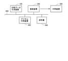
図2は、本発明の第1の実施形態における印刷システムの全体構成図である。この印刷システムは、PDFファイルなどの入稿データに対して各種処理を施して印刷データを生成する印刷データ生成装置100と、印刷データに基づいて印刷版を作製する製版装置200と、その製版装置200で作製された印刷版を使用して印刷を行う印刷装置300と、印刷版を用いることなくデジタルデータである印刷データに基づいて印刷を行うインクジェット印刷機・コピー機等のデジタル印刷装置400と、色の測定を行う測色機500とによって構成されている。印刷データ生成装置100と製版装置200とデジタル印刷装置400と測色機500とは、通信回線600によって互いに通信可能に接続されている。なお、本実施形態で使用される測色機500は分光測色機である。
<1. First Embodiment>
<1.1 Overall configuration of printing system>
FIG. 2 is an overall configuration diagram of the printing system according to the first embodiment of the present invention. This printing system includes a print
本実施形態では、印刷データ生成装置100において、CxFチャートに含まれるべきパッチの色を予測するためのモデル(学習モデル)である色予測モデルの構築が行われる。この色予測モデルを用いることにより、CxFチャートの印刷が行われていない特色についても、CxFチャートが印刷されたと仮定した場合の各パッチの色値(分光反射率)を取得することができる。印刷データ生成装置100では、このような色予測モデルの構築に必要となるCxFチャートを作成するための印刷データの生成も行われる。また、印刷データ生成装置100では、複数の色のインクの重ね刷りによって得られる色(典型的には、複数の特色のインクの重ね刷りが行われた部分あるいは特色のインクとプロセスカラーのインクとの重ね刷りが行われた部分の色)を予測するオーバープリント予測処理が行われる。オーバープリント予測処理では、必要に応じて、色予測モデルによる予測結果(分光反射率の予測値)が用いられる。さらに、印刷データ生成装置100では、オーバープリント予測処理で得られたデータをデジタル印刷装置400での印刷出力が可能な形式の印刷データに変換する処理も行われる。なお、オーバープリント予測処理の具体的な手法については、上述したDeshpandeらの手法を採用しても良いし、それとは別の手法を採用しても良い。
In the present embodiment, in the print
<1.2 印刷データ生成装置の構成>
図3は、本実施形態における印刷データ生成装置100のハードウェア構成図である。この印刷データ生成装置100は、パソコンによって実現されており、CPU11と、ROM12と、RAM13と、補助記憶装置14と、キーボード等の入力操作部15と、表示部16と、光学ディスクドライブ17と、ネットワークインタフェース部18とを有している。通信回線600経由で送られてくる入稿データは、ネットワークインタフェース部18を介して印刷データ生成装置100の内部へと入力される。印刷データ生成装置100で生成された印刷データは、ネットワークインタフェース部18を介して通信回線600経由でデジタル印刷装置400に送られる。
<1.2 Configuration of print data generator>
FIG. 3 is a hardware configuration diagram of the print
色予測モデルを構築するためのプログラム(以下、「色予測モデル構築プログラム」という。)141は補助記憶装置14に格納されている。色予測モデル構築プログラム141は、CD-ROMやDVD-ROM等のコンピュータ読み取り可能な記録媒体に格納されて提供される。すなわちユーザは、例えば、色予測モデル構築プログラム141の記録媒体としての光学ディスク(CD-ROM、DVD-ROM等)170を購入して光学ディスクドライブ17に装着し、その光学ディスク170から色予測モデル構築プログラム141を読み出して補助記憶装置14にインストールする。また、これに代えて、通信回線600を介して送られる色予測モデル構築プログラム141をネットワークインタフェース部18で受信して、それを補助記憶装置14にインストールするようにしてもよい。
A program for constructing a color prediction model (hereinafter referred to as “color prediction model construction program”) 141 is stored in the
なお、色予測モデル構築プログラム141が実行されると、膨大な量の計算処理が行われることが多い。そのため、プロセッサとしてCPU11に代えてGPUが設けられていても良いし、プロセッサとしてCPU11およびGPUが設けられていても良い。
When the color prediction
<1.3 色予測処理>
<1.3.1 概要>
まず、図1および図4を参照しつつ、色予測処理の概要を説明する。上述したように、CxFチャートを構成する22個のパッチのうちベタパッチPA2および紙白パッチPA1については、比較的容易に分光反射率を取得することができる。また、印刷の際に基材として同じ用紙が使用されるのであれば、インクの色に関わらず、紙白パッチPA1の分光反射率は一定である。そこで、本実施形態においては、ベタパッチPA2の分光反射率から色予測対象パッチ(CxFチャートを構成する22個のパッチのうちベタパッチPA2と紙白パッチPA1とを除くパッチ)の分光反射率を予測する色予測モデルが構築される。そして、当該色予測モデルを用いて、色予測対象インクについての色予測対象パッチの分光反射率が予測される。なお、本実施形態におけるベタパッチPA2のように色予測対象パッチの分光反射率の予測元となるパッチのことを「基準パッチ」という。
<1.3 Color prediction processing>
<1.3.1 Overview>
First, an outline of the color prediction process will be described with reference to FIGS. 1 and 4. As described above, the spectral reflectance of the solid patch PA2 and the paper white patch PA1 among the 22 patches constituting the CxF chart can be obtained relatively easily. Further, if the same paper is used as the base material during printing, the spectral reflectance of the white paper patch PA1 is constant regardless of the color of the ink. Therefore, in the present embodiment, the spectral reflectance of the color prediction target patch (the patch excluding the solid patch PA2 and the white patch PA1 among the 22 patches constituting the CxF chart) is predicted from the spectral reflectance of the solid patch PA2. A color prediction model is built. Then, using the color prediction model, the spectral reflectance of the color prediction target patch for the color prediction target ink is predicted. A patch that is a source of prediction of the spectral reflectance of a patch subject to color prediction, such as the solid patch PA2 in the present embodiment, is referred to as a “reference patch”.
本実施形態においては、色予測モデルは機械学習を行うニューラルネットワーク73によって実現される(図4参照)。色予測処理は、概略的には、学習段階の処理と予測(推論)段階の処理とに分けられる。学習段階では、ニューラルネットワーク73に教師データが与えられ、当該教師データを用いた機械学習がニューラルネットワーク73で行われる。ニューラルネットワーク73には、教師データとして、CxFチャート内のパッチの測色によって得られる分光反射率が与えられる。なお、本実施形態においては、1つの教師データは、ベタパッチPA2の測色によって得られる36個の分光反射率と1つの色予測対象パッチの測色によって得られる36個の分光反射率とによって構成される。予測段階では、学習済みのニューラルネットワーク73に、色予測対象インクについてのベタパッチ(基準パッチ)PA2の分光反射率が与えられる。これにより、ニューラルネットワーク73から色予測対象インクについての色予測対象パッチの分光反射率(予測値)が出力される。
In this embodiment, the color prediction model is realized by a
<1.3.2 詳細>
図5は、本実施形態で用いられるニューラルネットワーク73の構造の一例を示す図である。このニューラルネットワーク73は、入力層と隠れ層(中間層)と出力層とによって構成されている。入力層は、36個の分光反射率75(1)~75(36)を受け取る36個のユニット(ニューロン)によって構成されている。隠れ層も36個のユニットによって構成されている。但し、隠れ層のユニット数は36には限定されない。また、図5に示す例では隠れ層の層数は1であるが、隠れ層の層数は2以上であっても良い。出力層は、36個の分光反射率76(1)~76(36)を出力する36個のユニットによって構成されている。
<1.3.2 Details>
FIG. 5 is a diagram showing an example of the structure of the
入力層-隠れ層間の結合および隠れ層-出力層間の結合は、全結合である。隠れ層および出力層の活性化関数にはシグモイド関数が採用される。但し、シグモイド関数以外の関数を活性化関数として採用しても良い。 The bond between the input layer and the hidden layer and the bond between the hidden layer and the output layer are full bonds. The sigmoid function is adopted as the activation function of the hidden layer and the output layer. However, a function other than the sigmoid function may be adopted as the activation function.
このニューラルネットワーク73を用いた学習時には、分光反射率75(1)~75(36)が入力層に与えられる。これにより、ニューラルネットワーク73内で順伝播の処理が行われ、出力層から出力される分光反射率76(1)~76(36)と正解データである分光反射率77(1)~77(36)との2乗誤差の総和が求められる(図6参照)。そして、誤差の逆伝播の処理で得られる結果に基づいて勾配降下法を用いることによって、ニューラルネットワーク73のパラメータ(重み係数、バイアス)が更新される。以上のようにして学習が繰り返されることによって、上記パラメータが最適化される。なお、学習手法については、全ての教師データをまとめてニューラルネットワーク73に与えるバッチ学習を採用しても良いし、教師データを複数のグループに分割してグループ毎に教師データをニューラルネットワーク73に与えるミニバッチ学習を採用しても良いし、教師データを1つずつニューラルネットワーク73に与えるオンライン学習を採用しても良い。
At the time of learning using this
このニューラルネットワーク73を用いた予測時(推論時)には、色予測対象インクについてのベタパッチPA2の分光反射率75(1)~75(36)が入力層に与えられる。そして、ニューラルネットワーク73内で順伝播の処理が行われることによって出力層から出力される分光反射率76(1)~76(36)が、色予測対象インクについての色予測対象パッチの分光反射率の予測値として扱われる。
At the time of prediction (inference) using the
ところで、図5に示したニューラルネットワーク73は、色予測対象パッチ毎に用意される。本実施形態では、20個のパッチが色予測対象パッチとされるので、図7に示すように20個のニューラルネットワーク73(1)~73(20)が用意される。そして、色予測対象パッチ毎に、対応するニューラルネットワーク73を用いて学習および予測(推論)が行われる。
By the way, the
<1.3.3 処理手順>
次に、図8および図9に示すフローチャートを参照しつつ、色予測処理の手順について説明する。図8に示すように、まず、色予測モデルとして構築されるべきニューラルネットワーク73での学習に必要な教師データを取得する処理が行われる(ステップS100)。ステップS100では、分光反射率の予測が精度良く行われるよう、充分な数の教師データを取得することが好ましい。ステップS100は、詳しくは、図9に示すように、CxFチャートを印刷するステップ(ステップS102)と分光反射率を測定するステップ(ステップS104)とからなる。ステップS102およびステップS104の処理については、図10を参照しつつ、詳しく説明する。
<1.3.3 Processing procedure>
Next, the procedure of the color prediction process will be described with reference to the flowcharts shown in FIGS. 8 and 9. As shown in FIG. 8, first, a process of acquiring teacher data necessary for learning in the
ステップS102では、まず、印刷データ生成装置100でCxFチャート出力用の印刷データDchが作成され、当該印刷データDchが製版装置200に送られる。製版装置200では、印刷データDchに基づいて印刷版PLが作製される。そして、その印刷版PLを用いて、印刷装置300で印刷が実行される。これにより、印刷装置300からCxFチャートCHが出力される。
In step S102, first, the print
ステップS104では、測色機500によって、ステップS102で印刷されたCxFチャートCHに含まれるパッチの測色が行われる。測色機500による測色で得られた測色データDcmは、印刷データ生成装置100に送られる。上述したように、本実施形態で使用される測色機500は分光測色機である。従って、測色で得られる測色データDcmは、分光反射率のデータである。本実施形態においては、分光反射率のデータは、380~730nmの波長範囲で10nm刻みで得られる。従って、CxFチャートCHの任意の1つのパッチの測色を行うことによって、36個の分光反射率のデータが得られる。
In step S104, the
教師データの取得後、ニューラルネットワーク73によって、ステップS100で得られた教師データを用いた機械学習が行われる(ステップS110)。上述したように、本実施形態においては、この機械学習は、色予測対象パッチ毎に、対応するニューラルネットワーク73を用いて行われる。ステップS110での機械学習によって、ニューラルネットワーク73のパラメータ(重み係数、バイアス)が最適化される。その最適化されたパラメータを有するニューラルネットワーク73が、色の予測に使用される色予測モデルとなる。以上のように、ステップS110では、CxFチャート内のパッチの色を予測する色予測モデルが構築される。
After the teacher data is acquired, the
なお、ステップS100およびステップS110の処理(図8で符号61を付した部分の処理)については、1度だけ行われれば良く、1つの色予測対象インクの処理毎に行われる必要はない。これに対して、ステップS120およびステップS130の処理(図8で符号62を付した部分の処理)は、1つの色予測対象インクの処理毎に行われる必要がある。
The processing of steps S100 and S110 (processing of the portion designated with
ステップS120では、測色機500を用いて、色予測対象インクについてのベタパッチPA2の分光反射率が測定される。上述したように、ベタパッチの分光反射率は、例えば、色玉や印刷物に含まれる該当色の部分の測色を行うことによって得られる。また、ベタパッチの分光反射率を該当色の色見本の分光反射率で代用することもできる。
In step S120, the spectral reflectance of the solid patch PA2 for the color prediction target ink is measured by using the
次に、ステップS110で構築された色予測モデルとしてのニューラルネットワーク73に入力データとしてステップS120で得られた分光反射率を与えることによって、色予測対象インクについての色予測対象パッチの分光反射率(予測値)が求められる(ステップS130)。このステップS130では、20個の色予測対象パッチのそれぞれについて、36個の分光反射率が求められる。ところで、ベタパッチPA2の分光反射率はステップS120で得られている。また、紙白パッチPA1の分光反射率については、同じ用紙が使用される限り、過去の測定値を用いることができる。以上より、実際には色予測対象インクについてのCxFチャートが印刷されていなくても、当該CxFチャートが印刷されたと仮定した場合の全てのパッチの分光反射率が得られる。
Next, by giving the spectral reflectance obtained in step S120 as input data to the
なお、本実施形態においては、ステップS100によって教師データ取得ステップが実現され、ステップS110によって学習ステップが実現され、ステップS120によって第2の分光特性測定ステップが実現され、ステップS130によって分光特性予測ステップが実現されている。また、ステップS102によってカラーチャート印刷ステップが実現され、ステップS104によって第1の分光特性測定ステップが実現されている。 In the present embodiment, the teacher data acquisition step is realized by step S100, the learning step is realized by step S110, the second spectral characteristic measurement step is realized by step S120, and the spectral characteristic prediction step is realized by step S130. It has been realized. Further, the color chart printing step is realized by step S102, and the first spectral characteristic measurement step is realized by step S104.
<1.4 実験結果>
上記ニューラルネットワーク73を用いた分光反射率の予測の実験結果について説明する。図11は、第1タイプパッチ71についての実験結果を示すグラフである。図12は、第2タイプパッチ72についての実験結果を示すグラフである。図11および図12において、A部には各波長についての反射率の実測値をパッチ毎の実線で表しており、B部には各波長についての反射率の予測値をパッチ毎の実線で表している。各グラフに関し、横軸は波長(単位:nm)であり、縦軸は反射率である。なお、図11および図12に関し、符号とCxFチャートにおける特色の網点パーセントとの対応関係は「M(0):0%、M(1):10%、M(2):20%、M(3):30%、M(4):40%、M(5):50%、M(6):60%、M(7):70%、M(8):80%、M(9):90%、M(10):100%」となっている。
<1.4 Experimental results>
The experimental result of the prediction of the spectral reflectance using the
図11から、第1タイプパッチ71については中間調の予測精度がやや低いものの全体的には充分な精度で予測が行われていることが把握される。なお、中間調のパッチの分光反射率については、紙白パッチPA1の分光反射率とベタパッチPA2の分光反射率とに基づいて補間計算を行うことによって求めることもできる。
From FIG. 11, it can be seen that the
第2タイプパッチ72については、図12のA部に着目すると、約480nm以下の波長領域では特色の濃度が低いほど反射率が高いのに対して、約480nm以上の波長領域では特色の濃度が高いほど反射率が高い。本来的にはインクが多く重ねられるほど反射率は低くなるが、約480nm以上の波長領域ではインクが多く重ねられるほど反射率が高くなっている。これは、特色のインクの中に不透明成分が存在しており不透明部分での光の反射が生じているためと考えられる。図12のB部に示すように、約480nmの波長を境とするこのような反射率の逆転現象が予測値についても生じている。すなわち、ニューラルネットワーク73において上記のような不透明成分の影響を考慮して分光反射率の予測が行われていることが把握される。
Regarding the
また、実験によれば、第2タイプパッチ72に関して、実測値と予測値との色差(すなわち予測誤差)が特色の濃度に関わらず5前後の値であった。なお、色差は、次のようにして求められる。まず、実測値および予測値のそれぞれについて、分光反射率から所定の計算式によって三刺激値X,Y,およびZを求める。次に、実測値および予測値のそれぞれについて、三刺激値X,Y,およびZから所定の変換式によってLab値(L値、a値、およびb値)を求める。次に、L値、a値、およびb値のそれぞれについて、実測値と予測値との差を求める。それによって得られた3つの差の2乗和の平方根の値(正の値)が色差である。ここで、墨ベタパッチPA3の分光反射率が得られると仮定して、全ての第2タイプパッチ72の分光反射率を墨ベタパッチPA3の分光反射率で代用することを考える。この場合、特色の濃度が高いパッチほど色差が大きくなる。第2タイプパッチ72のうち特色の網点パーセントが100%のパッチでは色差は約13となった。本実施形態に係るニューラルネットワーク73を用いて予測を行った場合には特色の濃度に関わらず色差は約5であったので、本実施形態の手法の優位性が理解される。
Further, according to the experiment, the color difference (that is, the prediction error) between the measured value and the predicted value was about 5 for the
<1.5 効果>
本実施形態によれば、複数の色のインクの重ね刷りによって得られる色の予測に用いられるCxFチャート(図1参照)に関し、ベタパッチPA2と紙白パッチPA1とを除くパッチを色予測対象パッチとして、ベタパッチPA2の分光反射率と色予測対象パッチの分光反射率との関係の学習がニューラルネットワーク73によって行われる。これにより、CxFチャートに含まれるべきパッチの色を予測する色予測モデルが構築される。そして、その色予測モデルを用いて、色予測対象インクについての色予測対象パッチの分光反射率(予測値)が求められる。すなわち、色予測対象インクについてのCxFチャートを印刷することなく、当該CxFチャートが印刷されたと仮定した場合の各パッチの分光反射率が得られる。従って、CxFチャートの印刷や測色が不要となる。以上より、複数の色のインクの重ね刷りによって得られる色の予測を従来よりも低コストおよび少ない工数で行うことが可能となる。
<1.5 effect>
According to the present embodiment, with respect to the CxF chart (see FIG. 1) used for color prediction obtained by overprinting inks of a plurality of colors, patches other than the solid patch PA2 and the paper white patch PA1 are used as color prediction target patches. The
<1.6.変形例>
以下、上記第1の実施形態の変形例について説明する。
<1.6. Modification example>
Hereinafter, a modified example of the first embodiment will be described.
<1.6.1 第1の変形例>
上記第1の実施形態においては、ベタパッチPA2の分光反射率に基づいて色予測対象パッチの分光反射率が予測されていた。しかしながら、本発明はこれに限定されず、ベタパッチPA2の分光反射率と紙白パッチPA1の分光反射率とに基づいて色予測対象パッチの分光反射率が予測されるようにしても良い。この場合、ニューラルネットワーク73の構造は、例えば図13に示すような構造となる。図13に示すように、入力層は、ベタパッチPA2についての36個の分光反射率75(1)~75(36)および紙白パッチPA1についての36個の分光反射率78(1)~78(36)を受け取る72個のユニットによって構成される。隠れ層は、例えば36個のユニットによって構成される。出力層は、上記第1の実施形態と同様、色予測対象パッチについての36個の分光反射率76(1)~76(36)を出力する36個のユニットによって構成される。学習時および予測時には、ベタパッチPA2の分光反射率75(1)~75(36)に加えて紙白パッチPA1の分光反射率78(1)~78(36)が入力データとしてニューラルネットワーク73に与えられる。
<1.6.1 First modification>
In the first embodiment, the spectral reflectance of the color prediction target patch is predicted based on the spectral reflectance of the solid patch PA2. However, the present invention is not limited to this, and the spectral reflectance of the color prediction target patch may be predicted based on the spectral reflectance of the solid patch PA2 and the spectral reflectance of the white paper patch PA1. In this case, the structure of the
本変形例によれば、印刷に使用される基材(印刷用紙)の特性も考慮してニューラルネットワーク73での学習が行われる。このため、該当の基材に印刷が行われた場合の分光反射率の予測が、より精度良く行われる。
According to this modification, learning is performed by the
<1.6.2 第2の変形例>
また、ベタパッチPA2の分光反射率と墨ベタパッチPA3の分光反射率とに基づいて色予測対象パッチの分光反射率が予測されるようにしても良い。この場合、上記第1の変形例と同様の構造のニューラルネットワーク73が用いられ、学習時および予測時には、ベタパッチPA2についての36個の分光反射率および墨ベタパッチPA3についての36個の分光反射率が入力データとしてニューラルネットワーク73に与えられる
<1.6.2 Second variant>
Further, the spectral reflectance of the color prediction target patch may be predicted based on the spectral reflectance of the solid patch PA2 and the spectral reflectance of the black solid patch PA3. In this case, a
本変形例によれば、墨ベタパッチPA3の分光反射率を考慮してニューラルネットワーク73での学習が行われる。このため、特に第2タイプパッチ72の分光反射率の予測が、より精度良く行われる。
According to this modification, learning is performed by the
<1.6.3 第3の変形例>
上記第1の実施形態においては、ニューラルネットワーク73には入力データとして分光反射率の値がそのまま与えられていた。しかしながら、本発明はこれには限定されず、分光反射率の各測定値に対して紙白パッチPA1の分光反射率を1とする正規化を施し、正規化によって得られた値を入力データとしてニューラルネットワーク73に与えるようにしても良い。
<1.6.3 Third variant>
In the first embodiment, the
本変形例によれば、紙白パッチPA1の分光反射率が基準となるように正規化が施されたデータがニューラルネットワーク73に与えられるので、印刷に使用される基材(印刷用紙)の特性を考慮して学習が行われる。このため、上記第1の変形例と同様、該当の基材に印刷が行われた場合の分光反射率の予測が、より精度良く行われる。
According to this modification, since the data normalized so that the spectral reflectance of the white paper patch PA1 is used as a reference is given to the
<1.6.4 第4の変形例>
上記第1の実施形態においては、色予測対象パッチの数に等しい数のニューラルネットワーク73が用意され、色予測対象パッチ毎に、対応するニューラルネットワーク73を用いて学習および予測(推論)が行われていた。しかしながら、本発明はこれに限定されず、1つのニューラルネットワーク73で全ての色予測対象パッチの処理が行われるようにしても良い。
<1.6.4 Fourth variant>
In the first embodiment, the number of
図14は、本変形例におけるニューラルネットワーク73の構造の一例を示す図である。なお、図14では、2つの層間を結合する線の図示を省略している。入力層-隠れ層間の結合および隠れ層-出力層間の結合は、全結合である。入力層および隠れ層については、上記第1の実施形態と同様の構造を有している。出力層は、全ての色予測対象パッチについての36個の分光反射率76(1)~76(36)を出力するように構成されている。すなわち、出力層には、20個の色予測対象パッチP(1)~P(20)の各々につき36個の分光反射率76(1)~76(36)を出力する36個のユニットが設けられている。
FIG. 14 is a diagram showing an example of the structure of the
本変形例においては、上記第1の実施形態とは異なり、入力層-隠れ層間のネットワークが全ての色予測対象パッチで共通化される。このため、上記第1の実施形態に比べて全体の処理速度が向上する。 In this modification, unlike the first embodiment, the network between the input layer and the hidden layer is shared by all the color prediction target patches. Therefore, the overall processing speed is improved as compared with the first embodiment.
<1.6.5 第5の変形例>
上記第1の実施形態においては、ベタパッチPA2の分光反射率に基づいて色予測対象パッチの分光反射率が予測されていた。すなわち、ベタパッチPA2を基準パッチとして分光反射率の予測が行われていた。しかしながら、本発明はこれに限定されず、中間調のパッチの分光反射率に基づいて他のパッチ(色予測対象パッチ)の分光反射率が予測されるようにしても良い。例えば、第1タイプパッチ71のうちの特色の網点パーセントが50%のパッチの分光反射率と他のパッチの分光反射率との関係をニューラルネットワーク73に学習させておき、基材上に網点パーセントを50%とする色予測対象インクが塗られた状態の分光反射率を学習済みのニューラルネットワーク73に与えることによって当該色予測対象インクについての色予測対象パッチの分光反射率(予測値)を求めるようにすることもできる。このように、中間調のパッチを基準パッチとして分光反射率の予測が行われるようにしても良い。
<1.6.5 Fifth variant>
In the first embodiment, the spectral reflectance of the color prediction target patch is predicted based on the spectral reflectance of the solid patch PA2. That is, the spectral reflectance was predicted using the solid patch PA2 as a reference patch. However, the present invention is not limited to this, and the spectral reflectance of another patch (the patch subject to color prediction) may be predicted based on the spectral reflectance of the patch of the halftone. For example, the
<1.6.6 第6の変形例>
上記第1の実施形態においては、第1タイプパッチ71と第2タイプパッチ72とからなるCxFチャートが使用される例を挙げて説明したが、模式的には図15に示すような3つの段からなるCxFチャートが使用されることもある。図15で符号81を付した段のパッチは第1タイプパッチである。図15で符号82を付した段のパッチは第2タイプパッチである。図15で符号83を付した段のパッチは、網点パーセントを50%とする黒色上に対象のインクを印刷することによって得られるパッチ(以下、「第3タイプパッチ」という。)である。
<1.6.6 Sixth Modification Example>
In the first embodiment described above, an example in which a CxF chart composed of a
上記のような第3タイプパッチ83の分光反射率を教師データに含めて予めニューラルネットワーク73で学習を行うことができるのであれば、色予測対象インクについての第3タイプパッチ83の分光反射率を学習済みのニューラルネットワーク73で予測することも可能となる。
If the spectral reflectance of the
<2.第2の実施形態>
本発明の第2の実施形態について説明する。但し、上記第1の実施形態と異なる点を中心に説明する。
<2. Second embodiment>
A second embodiment of the present invention will be described. However, the points different from the first embodiment will be mainly described.
<2.1 概要>
上記第1の実施形態においては、色予測対象インクについての色予測対象パッチの分光反射率を予測するために、ベタパッチPA2(図1参照)の分光反射率と色予測対象パッチの分光反射率との関係の学習が予めニューラルネットワーク73によって行われていた。これに対して、本実施形態においては、色予測対象インクについての色予測対象パッチの分光反射率を予測するために、ベタパッチPA2の分光反射率と色予測対象パッチのトーンバリュー(階調レベル)との関係の学習が予めニューラルネットワーク73によって行われる。すなわち、ニューラルネットワーク73の出力層からはトーンバリューが出力される。分光反射率の予測を行う際には、色予測対象インクについてのベタパッチPA2の分光反射率を学習済みのニューラルネットワーク73に与えることによって、色予測対象パッチのトーンバリュー(予測値)が得られる。そして、所定の変換式に基づき、トーンバリューから分光反射率が算出される。
<2.1 Overview>
In the first embodiment, in order to predict the spectral reflectance of the color prediction target patch for the color prediction target ink, the spectral reflectance of the solid patch PA2 (see FIG. 1) and the spectral reflectance of the color prediction target patch are used. The learning of the relationship was performed in advance by the
以下、本実施形態における色予測処理について説明する。なお、印刷システムの全体構成および印刷データ生成装置100の構成については、上記第1の実施形態と同様である(図2および図3を参照)。
Hereinafter, the color prediction process in the present embodiment will be described. The overall configuration of the printing system and the configuration of the print
<2.2 色予測処理>
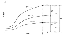
上述したように、本実施形態においては、ニューラルネットワーク73を用いてトーンバリューの予測が行われる。そこで、まず、図16を参照しつつ、トーンバリューについて説明する。図16に示すグラフは、横軸を波長とし、縦軸を反射率としている。符号84を付した曲線は、基材そのものの色(紙白)についての各波長の反射率を表している。符号85を付した曲線は、或るインクが基材上にベタ(網点パーセント100%)で塗られた状態の各波長の反射率を表している。符号86を付した曲線は、当該或るインクが基材上に或る網点パーセント(ここではQ%とする)で塗られた状態の各波長の反射率を表している。このとき、基材上に網点パーセントをQ%として当該或るインクが塗られた状態の波長WにおけるトーンバリューTVは、次式(4)で表される(図16参照)。
TV=V2/V1
=(V3-V5)/(V3-V4) ・・・(4)
<2.2 Color prediction processing>
As described above, in the present embodiment, the tone value is predicted using the
TV = V2 / V1
= (V3-V5) / (V3-V4) ... (4)
上式(4)より、次式(5)が成立する。すなわち、トーンバリューTVが得られていれば、次式(5)によって、基材上に網点パーセントをQ%として上記或るインクが塗られた状態の波長Wにおける反射率V5を求めることができる。
V5=V3-TV(V3-V4) ・・・(5)
From the above equation (4), the following equation (5) is established. That is, if the tone value TV is obtained, the reflectance V5 at the wavelength W in the state where the above-mentioned ink is applied can be obtained by the following equation (5) with the halftone dot percentage as Q%. can.
V5 = V3-TV (V3-V4) ... (5)
本実施形態においては、ニューラルネットワーク73を用いた予測時(推論時)には、図17に示すように、色予測対象インクについての色予測対象パッチのトーンバリュー87(1)~87(36)がニューラルネットワーク73から出力される。図17に示すように、このトーンバリュー87(1)~87(36)を分光反射率76(1)~76(36)に変換するための色値変換部88が設けられている。色値変換部88は、上式(5)によって、トーンバリュー87(1)~87(36)を分光反射率76(1)~76(36)に変換する。その際、上式(5)のV3には紙白パッチの分光反射率が代入され、上式(5)のV4にはベタパッチの分光反射率が代入される。
In the present embodiment, at the time of prediction (inference) using the
図18および図19に示すフローチャートを参照しつつ、本実施形態における色予測処理の手順について説明する。まず、ニューラルネットワーク73での学習に必要な教師データを取得する処理が行われる(ステップS200)。
The procedure of the color prediction processing in this embodiment will be described with reference to the flowcharts shown in FIGS. 18 and 19. First, a process of acquiring teacher data necessary for learning in the
図19に示すように、ステップS200は、CxFチャートを印刷するステップ(ステップS202)と、分光反射率を測定するステップ(ステップS204)と、分光反射率をトーンバリューに変換するステップ(ステップS206)とからなる。ステップS202では、上記第1の実施形態と同様にしてCxFチャートが印刷される。ステップS204では、上記第1の実施形態と同様にして分光反射率の測定が行われる。ステップS206では、上式(4)を用いて、ステップS204で得られた分光反射率をトーンバリューに変換する処理が行われる。このような処理が行われる理由は、本実施形態においてはベタパッチPA2の測色で得られる36個の分光反射率と1つの色予測対象パッチの測色で得られる36個の分光反射率に対応する36個のトーンバリューとによって1つの教師データが構成されるからである。 As shown in FIG. 19, step S200 includes a step of printing a CxF chart (step S202), a step of measuring the spectral reflectance (step S204), and a step of converting the spectral reflectance into a tone value (step S206). It consists of. In step S202, the CxF chart is printed in the same manner as in the first embodiment. In step S204, the spectral reflectance is measured in the same manner as in the first embodiment. In step S206, a process of converting the spectral reflectance obtained in step S204 into a tone value is performed using the above equation (4). The reason why such processing is performed corresponds to the 36 spectral reflectances obtained by the color measurement of the solid patch PA2 and the 36 spectral reflectances obtained by the color measurement of one color prediction target patch in the present embodiment. This is because one teacher data is composed of 36 tone values.
教師データの取得後、ニューラルネットワーク73によって、ステップS200で得られた教師データを用いた機械学習が行われる(ステップS210)。これにより、ニューラルネットワーク73のパラメータ(重み係数、バイアス)が最適化され、CxFチャート内のパッチの色を予測する色予測モデルが構築される。
After the teacher data is acquired, the
ステップS220では、上記第1の実施形態と同様、測色機500を用いて、色予測対象インクについてのベタパッチPA2の分光反射率が測定される。そして、ステップS210で構築された色予測モデルとしてのニューラルネットワーク73に入力データとしてステップS220で得られた分光反射率を与えることによって、色予測対象インクについての色予測対象パッチのトーンバリュー(予測値)が求められる(ステップS230)。このステップS230では、20個の色予測対象パッチのそれぞれについて、36個のトーンバリューが求められる。最後に、上式(5)に基づき、ステップS230で求められたトーンバリューから分光反射率が算出される(ステップS240)。
In step S220, the spectral reflectance of the solid patch PA2 for the color prediction target ink is measured by using the
なお、本実施形態においては、ステップS200によって教師データ取得ステップが実現され、ステップS210によって学習ステップが実現され、ステップS220によって第2の分光特性測定ステップが実現され、ステップS230によって階調レベル予測ステップが実現され、ステップS240によって分光特性算出ステップが実現されている。また、ステップS202によってカラーチャート印刷ステップが実現され、ステップS204によって第1の分光特性測定ステップが実現され、ステップS206によって色値変換ステップが実現されている。 In the present embodiment, the teacher data acquisition step is realized by step S200, the learning step is realized by step S210, the second spectral characteristic measurement step is realized by step S220, and the gradation level prediction step is realized by step S230. Is realized, and the spectral characteristic calculation step is realized by step S240. Further, a color chart printing step is realized by step S202, a first spectral characteristic measurement step is realized by step S204, and a color value conversion step is realized by step S206.
<2.3 効果>
上記第1の実施形態と同様、本実施形態によれば、複数の色のインクの重ね刷りによって得られる色の予測を従来よりも低コストおよび少ない工数で行うことが可能となる。
<2.3 effect>
Similar to the first embodiment, according to the present embodiment, it is possible to predict the color obtained by overprinting inks of a plurality of colors at a lower cost and less man-hours than in the conventional case.
<3.その他>
本発明は、上記各実施形態(変形例を含む)に限定されるものではなく、本発明の趣旨を逸脱しない範囲で種々変形して実施することができる。
<3. Others>
The present invention is not limited to each of the above embodiments (including modifications), and can be variously modified and implemented without departing from the spirit of the present invention.
上記各実施形態では、カラーチャートのパッチ等を測色機500で測色し、分光反射率を得た上で、色予測モデルが構築されている。しかし、分光反射率以外の測定値に基づいて色予測モデルを構築することもできる。例えば、分光吸収率(1から分光反射率を減ずることによって得られる値)や次式(6)から得られる分光吸収係数αに基づいても色予測モデルを構築することができる。なお、分光反射率、分光吸収率、および分光吸収係数等の測定値が「分光特性」に相当する。ある波長における紙白での反射率をR0とし、該当パッチの反射率をRとし、インクの厚みをxとすると、多重反射を考慮しない場合には、分光吸収係数αは次式(6)で表される。
α=-(1/(2x))・ln(R/R0) ・・・(6)
In each of the above embodiments, a color prediction model is constructed after measuring a patch or the like of a color chart with a
α =-(1 / (2x)) · ln (R / R 0 ) ... (6)
さらに、上記第1の実施形態(第6の変形例以外の変形例を含む)および上記第2の実施形態では図1に示すCxFチャート(第1タイプパッチ71および第2タイプパッチ72からなるCxFチャート)を用いて色予測モデルが構築され、上記第1の実施形態の第6の変形例では図15に示すCxFチャート(第1タイプパッチ81、第2タイプパッチ82、および第3タイプパッチ83からなるCxFチャート)を用いて色予測モデルが構築されている。しかし、第1タイプパッチのみからなる「簡易CxFチャート」を用いて色予測モデルを構築することもできる。
Further, in the first embodiment (including the modification other than the sixth modification) and the second embodiment, the CxF chart shown in FIG. 1 (CxF composed of the
73…ニューラルネットワーク
88…色値変換部
100…印刷データ生成装置
141…色予測モデル構築プログラム
200…製版装置
300…印刷装置
400…デジタル印刷装置
500…測色機
PA1…紙白パッチ
PA2…ベタパッチ
PA3…墨ベタパッチ
73 ...
Claims (17)
前記カラーチャート内の所定のパッチである基準パッチの分光特性と前記カラーチャート内の色予測対象パッチの色値とを含む複数の教師データを取得する教師データ取得ステップと、
入力データを前記基準パッチの分光特性とし出力データを前記色予測対象パッチの色値とするニューラルネットワークで前記複数の教師データを用いた機械学習を行う学習ステップと
を含むことを特徴とする、色予測モデル構築方法。 A method of constructing a color prediction model that predicts the color of a patch in a color chart containing a plurality of first-type patches obtained by applying ink on a substrate at multiple levels of ink density.
A teacher data acquisition step for acquiring a plurality of teacher data including the spectral characteristics of a reference patch which is a predetermined patch in the color chart and the color value of the color prediction target patch in the color chart.
A color characterized by including a learning step of performing machine learning using the plurality of teacher data in a neural network in which the input data is the spectral characteristic of the reference patch and the output data is the color value of the color prediction target patch. How to build a predictive model.
前記N個のパッチと1対1で対応するようにN個の前記ニューラルネットワークが用意され、
前記学習ステップでは、ニューラルネットワーク毎に、対応するパッチの色値と前記基準パッチの分光特性とを用いて機械学習が行われることを特徴とする、請求項1から3までのいずれか1項に記載の色予測モデル構築方法。 The color prediction target patch is N patches.
N neural networks are prepared so as to have a one-to-one correspondence with the N patches.
The learning step is characterized in that machine learning is performed using the color value of the corresponding patch and the spectral characteristics of the reference patch for each neural network, according to any one of claims 1 to 3. The described color prediction model construction method.
入力データを前記基準パッチの分光特性とし出力データを前記N個のパッチの色値とする1つだけの前記ニューラルネットワークが用意され、
前記学習ステップでは、前記1つだけのニューラルネットワークによって前記基準パッチの分光特性と前記N個のパッチの色値とを用いて機械学習が行われることを特徴とする、請求項1から3までのいずれか1項に記載の色予測モデル構築方法。 The color prediction target patch is N patches.
Only one neural network is prepared, in which the input data is the spectral characteristic of the reference patch and the output data is the color value of the N patches.
The learning step is characterized in that machine learning is performed by using only one neural network using the spectral characteristics of the reference patch and the color values of the N patches, according to claims 1 to 3. The color prediction model construction method according to any one of the items.
前記ニューラルネットワークは、入力層と隠れ層と出力層とを含み、
前記入力層には、前記基準パッチとしての1つのパッチにつきK個のユニットが設けられ、
前記出力層には、前記色予測対象パッチとしての1つのパッチにつきK個のユニットが設けられていることを特徴とする、請求項1から5までのいずれか1項に記載の色予測モデル構築方法。 The color of each patch in the color chart is identified by K spectral properties.
The neural network includes an input layer, a hidden layer, and an output layer.
The input layer is provided with K units for each patch as the reference patch.
The color prediction model construction according to any one of claims 1 to 5, wherein the output layer is provided with K units for one patch as the color prediction target patch. Method.
各教師データを生成するための前記カラーチャートの印刷を行うカラーチャート印刷ステップと、
前記カラーチャート印刷ステップで印刷されたカラーチャートに関して前記基準パッチの分光特性および前記色予測対象パッチの分光特性を測定する第1の分光特性測定ステップと
を含むことを特徴とする、請求項9に記載の色予測モデル構築方法。 The teacher data acquisition step is
A color chart printing step for printing the color chart for generating each teacher data, and
9. A aspect of claim 9, wherein the color chart printed in the color chart printing step includes a first spectral characteristic measuring step for measuring the spectral characteristics of the reference patch and the spectral characteristics of the color prediction target patch. The described color prediction model construction method.
各教師データを生成するための前記カラーチャートの印刷を行うカラーチャート印刷ステップと、
前記カラーチャート印刷ステップで印刷されたカラーチャートに関して前記基準パッチの分光特性および前記色予測対象パッチの分光特性を測定する第1の分光特性測定ステップと、
前記第1の分光特性測定ステップで測定された前記色予測対象パッチの分光特性を階調レベルに変換する色値変換ステップと
を含むことを特徴とする、請求項11に記載の色予測モデル構築方法。 The teacher data acquisition step is
A color chart printing step for printing the color chart for generating each teacher data, and
A first spectral characteristic measurement step for measuring the spectral characteristics of the reference patch and the spectral characteristics of the color prediction target patch with respect to the color chart printed in the color chart printing step.
The color prediction model construction according to claim 11, further comprising a color value conversion step of converting the spectral characteristics of the color prediction target patch measured in the first spectral characteristic measurement step into a gradation level. Method.
前記基準パッチは、前記複数の第1タイプパッチのうちインク濃度が最大のパッチおよび前記複数の第2タイプパッチのうちインク濃度が最小のパッチであることを特徴とする、請求項1に記載の色予測モデル構築方法。 The color chart further comprises a plurality of second type patches obtained by applying the ink onto the black ink at the plurality of ink densities.
The reference patch according to claim 1, wherein the reference patch is a patch having the highest ink density among the plurality of first type patches and a patch having the lowest ink density among the plurality of second type patches. How to build a color prediction model.
請求項9または10に記載の色予測モデル構築方法によって構築された色予測モデルである学習済みのニューラルネットワークに入力データとして前記第2の分光特性測定ステップで測定された分光特性を与えることによって前記色予測対象インクについての前記色予測対象パッチの分光特性を予測する分光特性予測ステップと
を含むことを特徴とする、色予測方法。 A second spectral characteristic measurement step for measuring the spectral characteristics of the reference patch for the color prediction target ink, which is the target ink for predicting the color of the patch in the color chart,
The said by giving the spectral characteristics measured in the second spectral characteristic measurement step as input data to the trained neural network which is the color prediction model constructed by the color prediction model construction method according to claim 9 or 10. A color prediction method comprising a spectral characteristic prediction step for predicting the spectral characteristics of the color prediction target patch for a color prediction target ink.
請求項11または12に記載の色予測モデル構築方法によって構築された色予測モデルである学習済みのニューラルネットワークに入力データとして前記第2の分光特性測定ステップで測定された分光特性を与えることによって前記色予測対象インクについての前記色予測対象パッチの階調レベルを予測する階調レベル予測ステップと、
前記階調レベル予測ステップで予測された階調レベルから所定の変換式によって分光特性を求める分光特性算出ステップと
を含むことを特徴とする、色予測方法。 A second spectral characteristic measurement step for measuring the spectral characteristics of the reference patch for the color prediction target ink, which is the target ink for predicting the color of the patch in the color chart,
The said by giving the spectral characteristics measured in the second spectral characteristic measurement step as input data to the trained neural network which is the color prediction model constructed by the color prediction model construction method according to claim 11 or 12. A gradation level prediction step for predicting the gradation level of the color prediction target patch for the color prediction target ink, and
A color prediction method comprising: a spectral characteristic calculation step of obtaining a spectral characteristic from a gradation level predicted in the gradation level prediction step by a predetermined conversion formula.
コンピュータに、
前記カラーチャート内の所定のパッチである基準パッチの分光特性と前記カラーチャート内の色予測対象パッチの色値とを含む複数の教師データを読み込む教師データ読み込みステップと、
入力データを前記基準パッチの分光特性とし出力データを前記色予測対象パッチの色値とするニューラルネットワークで前記複数の教師データを用いた機械学習を行う学習ステップと
を実行させるための色予測モデル構築プログラム。 A program for constructing a color prediction model that predicts the color of a patch in a color chart containing a plurality of first-type patches obtained by applying ink on a substrate at multiple levels of ink density.
On the computer
A teacher data reading step for reading a plurality of teacher data including the spectral characteristics of the reference patch which is a predetermined patch in the color chart and the color value of the color prediction target patch in the color chart.
Construction of a color prediction model for executing a learning step of performing machine learning using the plurality of teacher data in a neural network in which the input data is the spectral characteristics of the reference patch and the output data is the color value of the patch to be color predicted. program.
Priority Applications (2)
| Application Number | Priority Date | Filing Date | Title |
|---|---|---|---|
| JP2018240741A JP7033056B2 (en) | 2018-12-25 | 2018-12-25 | Color prediction model construction method, color prediction method, and color prediction model construction program |
| EP19219439.7A EP3675476B1 (en) | 2018-12-25 | 2019-12-23 | Color prediction model construction method and color prediction model construction program |
Applications Claiming Priority (1)
| Application Number | Priority Date | Filing Date | Title |
|---|---|---|---|
| JP2018240741A JP7033056B2 (en) | 2018-12-25 | 2018-12-25 | Color prediction model construction method, color prediction method, and color prediction model construction program |
Publications (3)
| Publication Number | Publication Date |
|---|---|
| JP2020102807A JP2020102807A (en) | 2020-07-02 |
| JP2020102807A5 JP2020102807A5 (en) | 2021-08-05 |
| JP7033056B2 true JP7033056B2 (en) | 2022-03-09 |
Family
ID=69005629
Family Applications (1)
| Application Number | Title | Priority Date | Filing Date |
|---|---|---|---|
| JP2018240741A Active JP7033056B2 (en) | 2018-12-25 | 2018-12-25 | Color prediction model construction method, color prediction method, and color prediction model construction program |
Country Status (2)
| Country | Link |
|---|---|
| EP (1) | EP3675476B1 (en) |
| JP (1) | JP7033056B2 (en) |
Cited By (1)
| Publication number | Priority date | Publication date | Assignee | Title |
|---|---|---|---|---|
| WO2023214767A1 (en) * | 2022-05-04 | 2023-11-09 | 주식회사 케이씨씨 | Method for predicting dry paint color value from liquid paint color value |
Families Citing this family (3)
| Publication number | Priority date | Publication date | Assignee | Title |
|---|---|---|---|---|
| JP7299048B2 (en) * | 2019-03-26 | 2023-06-27 | 株式会社Screenホールディングス | Color prediction method and color prediction program |
| CN111860987A (en) * | 2020-07-08 | 2020-10-30 | 江苏科慧半导体研究院有限公司 | Mixed fluorescent material emission spectrum prediction method and device |
| JP2022052633A (en) | 2020-09-23 | 2022-04-04 | 株式会社Screenホールディングス | Color chart data correction method and color chart data correction program |
Citations (3)
| Publication number | Priority date | Publication date | Assignee | Title |
|---|---|---|---|---|
| JP2009111667A (en) | 2007-10-30 | 2009-05-21 | Seiko Epson Corp | Prediction of printing result |
| JP2012080279A (en) | 2010-09-30 | 2012-04-19 | Fujifilm Corp | Device, method and program for color reproduction prediction |
| JP2016082598A (en) | 2014-10-20 | 2016-05-16 | ハイデルベルガー ドルツクマシーネン アクチエンゲゼルシヤフトHeidelberger Druckmaschinen AG | Method for calculating spot color database |
Family Cites Families (6)
| Publication number | Priority date | Publication date | Assignee | Title |
|---|---|---|---|---|
| JP2568710B2 (en) * | 1989-12-29 | 1997-01-08 | 松下電器産業株式会社 | Drawing control method |
| JP3208907B2 (en) | 1993-03-25 | 2001-09-17 | 東洋インキ製造株式会社 | Color value correction device |
| JPH07212609A (en) * | 1994-01-14 | 1995-08-11 | Toyo Ink Mfg Co Ltd | Device for converting color density into color value |
| JPH07322082A (en) * | 1994-05-27 | 1995-12-08 | Toyo Ink Mfg Co Ltd | Color separation device |
| JP4247639B2 (en) * | 2006-06-14 | 2009-04-02 | セイコーエプソン株式会社 | Generate a color conversion profile for printing |
| US8208170B2 (en) * | 2008-10-10 | 2012-06-26 | Xerox Corporation | System and method for printing target colors with process colors utilizing parallel feedforward neural networks |
-
2018
- 2018-12-25 JP JP2018240741A patent/JP7033056B2/en active Active
-
2019
- 2019-12-23 EP EP19219439.7A patent/EP3675476B1/en active Active
Patent Citations (3)
| Publication number | Priority date | Publication date | Assignee | Title |
|---|---|---|---|---|
| JP2009111667A (en) | 2007-10-30 | 2009-05-21 | Seiko Epson Corp | Prediction of printing result |
| JP2012080279A (en) | 2010-09-30 | 2012-04-19 | Fujifilm Corp | Device, method and program for color reproduction prediction |
| JP2016082598A (en) | 2014-10-20 | 2016-05-16 | ハイデルベルガー ドルツクマシーネン アクチエンゲゼルシヤフトHeidelberger Druckmaschinen AG | Method for calculating spot color database |
Cited By (1)
| Publication number | Priority date | Publication date | Assignee | Title |
|---|---|---|---|---|
| WO2023214767A1 (en) * | 2022-05-04 | 2023-11-09 | 주식회사 케이씨씨 | Method for predicting dry paint color value from liquid paint color value |
Also Published As
| Publication number | Publication date |
|---|---|
| EP3675476B1 (en) | 2023-11-15 |
| EP3675476A1 (en) | 2020-07-01 |
| JP2020102807A (en) | 2020-07-02 |
Similar Documents
| Publication | Publication Date | Title |
|---|---|---|
| JP7033056B2 (en) | Color prediction model construction method, color prediction method, and color prediction model construction program | |
| JP7299048B2 (en) | Color prediction method and color prediction program | |
| EP2629978B1 (en) | Image processing apparatus and image processing method | |
| JP5014475B2 (en) | Image processing apparatus and image processing method | |
| CN102035991B (en) | Profile generating method and device | |
| JP4800380B2 (en) | Colorimetric value prediction method for subtractive color mixture | |
| JP2012034032A (en) | Image processing apparatus, and image processing method | |
| JP2022052632A (en) | Color prediction method and color prediction program | |
| JP7353763B2 (en) | Color prediction method and color prediction program | |
| JP5840227B2 (en) | Data generation method and data generation apparatus | |
| JP5682759B2 (en) | Bronzing index value calculation method and bronzing index value calculation device | |
| JP7082919B2 (en) | Color prediction method, print data generation method, print data generation device, and color prediction program | |
| US11659131B2 (en) | Method and computer program product for predicting spectral characteristics of ink applied to a base material | |
| JP2022052633A (en) | Color chart data correction method and color chart data correction program | |
| JP7220823B2 (en) | Color prediction method | |
| JP4131204B2 (en) | Reproduction color prediction method | |
| KR20170032851A (en) | Image processing apparatus and image processing method | |
| JP2011151491A (en) | Device and program for color conversion | |
| JP2023086179A (en) | Color data conversion method, color data conversion device, and color data conversion program | |
| JPS59176980A (en) | Picture processing method |
Legal Events
| Date | Code | Title | Description |
|---|---|---|---|
| A621 | Written request for application examination |
Free format text: JAPANESE INTERMEDIATE CODE: A621 Effective date: 20210618 |
|
| A521 | Request for written amendment filed |
Free format text: JAPANESE INTERMEDIATE CODE: A523 Effective date: 20210623 |
|
| A977 | Report on retrieval |
Free format text: JAPANESE INTERMEDIATE CODE: A971007 Effective date: 20220215 |
|
| TRDD | Decision of grant or rejection written | ||
| A01 | Written decision to grant a patent or to grant a registration (utility model) |
Free format text: JAPANESE INTERMEDIATE CODE: A01 Effective date: 20220222 |
|
| A61 | First payment of annual fees (during grant procedure) |
Free format text: JAPANESE INTERMEDIATE CODE: A61 Effective date: 20220225 |
|
| R150 | Certificate of patent or registration of utility model |
Ref document number: 7033056 Country of ref document: JP Free format text: JAPANESE INTERMEDIATE CODE: R150 |