EP3675476B1 - Color prediction model construction method and color prediction model construction program - Google Patents
Color prediction model construction method and color prediction model construction program Download PDFInfo
- Publication number
- EP3675476B1 EP3675476B1 EP19219439.7A EP19219439A EP3675476B1 EP 3675476 B1 EP3675476 B1 EP 3675476B1 EP 19219439 A EP19219439 A EP 19219439A EP 3675476 B1 EP3675476 B1 EP 3675476B1
- Authority
- EP
- European Patent Office
- Prior art keywords
- color
- patch
- color prediction
- prediction model
- patches
- Prior art date
- Legal status (The legal status is an assumption and is not a legal conclusion. Google has not performed a legal analysis and makes no representation as to the accuracy of the status listed.)
- Active
Links
- 238000010276 construction Methods 0.000 title claims description 18
- 230000003595 spectral effect Effects 0.000 claims description 177
- 238000013528 artificial neural network Methods 0.000 claims description 79
- 238000007639 printing Methods 0.000 claims description 75
- 238000000034 method Methods 0.000 claims description 61
- 239000000463 material Substances 0.000 claims description 29
- 238000010801 machine learning Methods 0.000 claims description 11
- 238000010521 absorption reaction Methods 0.000 claims description 7
- 238000005259 measurement Methods 0.000 claims description 7
- 238000006243 chemical reaction Methods 0.000 claims description 5
- 230000007935 neutral effect Effects 0.000 claims 1
- 239000000976 ink Substances 0.000 description 74
- 239000007787 solid Substances 0.000 description 44
- 238000004737 colorimetric analysis Methods 0.000 description 31
- 238000012986 modification Methods 0.000 description 25
- 230000004048 modification Effects 0.000 description 25
- 239000003086 colorant Substances 0.000 description 24
- 241000533901 Narcissus papyraceus Species 0.000 description 22
- 238000010586 diagram Methods 0.000 description 20
- 238000012545 processing Methods 0.000 description 8
- 238000004891 communication Methods 0.000 description 6
- 230000006870 function Effects 0.000 description 5
- 230000003287 optical effect Effects 0.000 description 5
- 238000004364 calculation method Methods 0.000 description 4
- 238000012937 correction Methods 0.000 description 3
- 238000013461 design Methods 0.000 description 3
- 230000000694 effects Effects 0.000 description 3
- 230000004913 activation Effects 0.000 description 2
- 230000001965 increasing effect Effects 0.000 description 2
- 238000002372 labelling Methods 0.000 description 2
- 238000004519 manufacturing process Methods 0.000 description 2
- 238000010606 normalization Methods 0.000 description 2
- 238000004806 packaging method and process Methods 0.000 description 2
- 239000000758 substrate Substances 0.000 description 2
- 239000000654 additive Substances 0.000 description 1
- 230000000996 additive effect Effects 0.000 description 1
- 230000007423 decrease Effects 0.000 description 1
- 230000001419 dependent effect Effects 0.000 description 1
- 230000002708 enhancing effect Effects 0.000 description 1
- 238000002474 experimental method Methods 0.000 description 1
- 238000011478 gradient descent method Methods 0.000 description 1
- 238000007646 gravure printing Methods 0.000 description 1
- 210000002569 neuron Anatomy 0.000 description 1
- 238000007645 offset printing Methods 0.000 description 1
Images


Classifications
-
- H—ELECTRICITY
- H04—ELECTRIC COMMUNICATION TECHNIQUE
- H04N—PICTORIAL COMMUNICATION, e.g. TELEVISION
- H04N1/00—Scanning, transmission or reproduction of documents or the like, e.g. facsimile transmission; Details thereof
- H04N1/46—Colour picture communication systems
- H04N1/56—Processing of colour picture signals
- H04N1/60—Colour correction or control
- H04N1/603—Colour correction or control controlled by characteristics of the picture signal generator or the picture reproducer
- H04N1/6033—Colour correction or control controlled by characteristics of the picture signal generator or the picture reproducer using test pattern analysis
Definitions
- the present invention relates to a method for constructing a color prediction model for predicting a color of a patch in a color chart used for predicting a color obtained by overprinting inks of a plurality of colors (typically, a plurality of colors including a spot color).
- X b , Y b , and Z b are tristimulus values of a background color
- X f , Y f , and Z f are tristimulus values of a foreground color
- j x , j y , and j z are scaling coefficients
- k x , k y , and k z are constants.
- j x , j y , j z , k x , k y , and k z are collectively referred to as "overprint coefficient".
- color reproduction methods include additive color mixing and subtractive color mixing.
- the subtractive color mixing is applied for color reproduction.
- the stimulus value X of the color obtained by overprinting is represented by "X b ⁇ X f " (the same applies to the stimulus values Y and Z), for example.
- a correction using a linear equation is performed as shown in the above Equations (1) to (3).
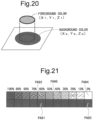
- a color chart as schematically shown in Fig. 21 is used, for example.
- This color chart is called a "CxF chart".
- the CxF chart is composed of twenty-two patches.
- the eleven patches in the upper part are patches obtained by printing an ink of a target spot color on a base material such as paper at a dot percentage in increments of 10%.
- the eleven patches in the lower part are patches obtained by printing an ink of a target spot color on black (black solid) at a dot percentage in increments of 10%.
- the overprint prediction value is calculated using the value (colorimetry value) obtained by the colorimetry of the patches in the CxF chart described above.
- Deshpande et al. method will be described in detail with reference to the flowchart in Fig. 22 , taking, as an example, calculation of an overprint prediction value in the case where a background color is a spot color at a dot percentage of 40% (referred to as a "spot color 1" for convenience) and a foreground color is another spot color at a dot percentage of 60% (referred to as a “spot color 2" for convenience).
- the CxF chart is printed using the ink of spot color 1, and further, the CxF chart is printed using the ink of spot color 2 (step S900).
- the overprint coefficients j x , j y , j z , k x , k y , and k z of the above Equations (1) to (3) regarding the spot color 2 are calculated using the CxF chart printed using the ink of spot color 2 (referred to as "spot color 2 chart" for convenience) (step S910).
- spot color 2 chart for convenience
- the practical maximum value and the minimum value for X b ⁇ X f are values obtained by the ink of the spot color 2 being applied on the base material and black (black solid), respectively.
- Y b ⁇ Y f and Z b ⁇ Z f are values obtained by the ink of the spot color 2 being applied on the base material and black (black solid), respectively. The same applies to Y b ⁇ Y f and Z b ⁇ Z f .
- a coordinate system representing the above Equations (1) to (3) in order to calculate the overprint coefficient, in a coordinate system representing the above Equations (1) to (3) (see Fig. 23 .
- the coordinates representing the stimulus value of a state where the ink of the spot color 2 at a dot percentage of 60% is applied on black are defined as a first calibration point P91
- the coordinates representing the stimulus value of a state where the ink of the spot color 2 at a dot percentage of 60% is applied on the base material are defined as a second calibration point P92.
- X values are assigned as follows for the first calibration point P91 with respect to the above Equation (1).
- the value obtained by colorimetry of the patch PA93 in the spot color 2 chart black stimulus value
- X b the value obtained by colorimetry of the patch PA92 in the spot color 2 chart
- X f the value obtained by colorimetry of the patch PA91 in the spot color 2 chart
- X the value obtained by colorimetry of the patch PA91 in the spot color 2 chart
- the overprint coefficients j x and k x are calculated by solving a simultaneous equation consisting of the equation relating to the first calibration point P91 and the equation relating to the second calibration point P92. That is, an equation representing a straight line denoted by reference numeral L91 in Fig. 23 is obtained.
- the overprint coefficients j y , j z , k y , and k z are similarly calculated.
- an overprint coefficient corresponding to the dot percentage between two patches which are adjacent to each other in the horizontal direction can be obtained on the basis of the colorimetric values obtained by linear interpolation.
- the values of X b , Y b , and Z b (tristimulus values of the background color) for calculating final overprint prediction values in the above Equations (1) to (3) are obtained using the CxF chart printed using the ink of spot color 1 (referred to as "spot color 1 chart" for convenience) (step S920). Specifically, the values of X b , Y b , and Z b are obtained by colorimetry of the patch PA95 (see Fig. 21 ) in the spot color 1 chart.
- the values of X f , Y f , and Z f (tristimulus values of the foreground color) for calculating the final overprint prediction values in the above Equations (1) to (3) are obtained using the spot color 2 chart (step S930). Specifically, the values of X f , Y f , and Z f are obtained by colorimetry of the patch PA92 (see Fig. 21 ) in the spot color 2 chart.
- step S940 the values obtained in steps S910 to S930 are substituted into the above Equations (1) to (3), whereby the tristimulus values X, Y, and Z as overprint prediction values are calculated (step S940).
- the values of X, X f , and X b relating to the first calibration point P91 are obtained by colorimetry of the patches PA91, PA92, and PA93 in the spot color 2 chart.
- the first calibration point P91 can be regarded as being located at the origin of the graph in Fig. 23 for simplicity. In this case, the colorimetry of the patches PA91 and PA93 in the spot color 2 chart is not necessary (the colorimetry of the patch PA92 is still necessary for obtaining the values of X and X f of the second calibration point P92).
- the tristimulus values X, Y, and Z as the overprint prediction values can be calculated without printing the lower patch group including the patches PA91 and PA93 in the CxF chart shown in Fig. 21 .
- the CxF chart having the upper patch group shown in Fig. 21 without having the lower patch group is herein referred to as a "simple CxF chart" for convenience.
- Japanese Laid-Open Patent Publication No. 6-281501 discloses a color value correction device for obtaining, from a color value obtained by a certain colorimetric device, a color value obtained by another colorimetric device using a neural network.
- a system for printing target colors includes a print-engine interface and a neural network component.
- the print-engine interface is in operative communication with a print engine of a printing system.
- the neural network component is calibrated to the print engine for printing a target color on a substrate.
- the neural network is in operative communication with the print-engine interface and communicates a parameter associated with printing the target color on the substrate utilizing the print engine.
- an object of the present invention is to enable prediction of a color of a patch to be included in a CxF chart so that a color obtained by overprinting inks of a plurality of colors can be predicted at lower cost and with fewer man-hours than ever before.
- This object is achieved by the subject-matters of the claims 1 and 15. Further advantageous embodiments of the invention are the subject-matter of the dependent claims. The invention is defined by claims 1 and 15. Aspects of the invention are set out below.
- One aspect of the present invention is directed to a color prediction model construction method for constructing a color prediction model for predicting a color of a patch in a color chart including a plurality of first type patches obtained by applying an ink on a base material with ink densities of a plurality of levels, the color prediction model construction method including:
- the relationship between the spectral characteristics of the reference patch and the color values of the color prediction target patch is learned by a neural network.
- a color prediction model for predicting a color of a patch to be included in the color chart is constructed.
- Another aspect of the present invention is directed to a color prediction model construction program for constructing a color prediction model for predicting a color of a patch in a color chart including a plurality of first type patches obtained by applying an ink on a base material with ink densities of a plurality of levels, the color prediction model construction program causing a computer to execute:
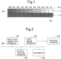
- each of upper patches in the CxF chart (each of patches in the part denoted by reference numeral 71 in Fig. 1 ) (a patch obtained by printing a target ink on a base material) is referred to as a "first type patch”
- each of lower patches in the CxF chart (each of patches in the part denoted by reference numeral 72 in Fig. 1 ) (a patch obtained by printing a target ink on black) is referred to as a "second type patch”.
- a patch representing the color of the base material itself (a patch marked with PA1 in Fig.
- a paper white patch a patch obtained by solidly applying the target ink all over the base material (at a dot percentage of 100%) (a patch marked with PA2 in Fig. 1 ) is referred to as a "solid patch”, and a patch obtained by solidly applying only a black ink all over the base material (a patch marked with PA3 in Fig. 1 ) is referred to as a "black solid patch”.
- the colorimetry result (colorimetric value) of the CxF chart is required to predict a color obtained by overprinting a plurality of color inks including a spot color ink.
- spectral reflectances which are colorimetric values can be relatively easily obtained for the solid patch PA2 and the paper white patch PA1 among 22 patches constituting the CxF chart. It should be noted that, in the following embodiments, the spectral reflectances are obtained in 10 nm increments in the wavelength range of 380 to 730 nm. However, it is not limited thereto.
- the spectral reflectances may be obtained in increments of a unit wavelength range of an appropriate size (for example, in 10 nm increments) in the wavelength range of 400 to 700 nm. That is, one color is specified by spectral reflectances, the number of the spectral reflectances (for example, 36) is obtained by dividing the wavelength range by the unit wavelength range.
- the spectral reflectances of the solid patch PA2 can be obtained, for example, by performing colorimetry of a portion of the corresponding color included in a colored ball or printed matter. Further, the spectral reflectances of the solid patch PA2 can be substituted with the spectral reflectances obtained by colorimetry of the color sample of the corresponding color. This is because the color sample represents a target color when the corresponding color is solidly applied.
- the spectral reflectances of the paper white patch PA1 are obtained by colorimetry of a portion on the base material where nothing is printed. Further, as long as the same paper is used as the base material when performing printing, each of the spectral reflectances of the paper white patch PA1 is constant regardless of an ink color. Therefore, even when processing is performed for a plurality of color inks, the spectral reflectances of the paper white patch PA1 needs to be measured only once, as long as the same paper is used. Note that the configuration may be such that spectral reflectances of the paper white patches PA1 of a plurality of CxF charts are measured and the average values thereof are used as the representative values of the respective spectral reflectances of the paper white patch PA1.
- the accurate spectral reflectances cannot be obtained unless the colorimetry of the matter actually printed on the base material or black is performed.
- the respective spectral reflectances for the plurality of spot colors are considered to be close to each other.
- the spectral reflectances of the solid patch PA2 and the spectral reflectances of each of the 20 patches have a certain relationship.
- the above 20 patches are taken as color prediction target patches, and after the relationship between the spectral reflectances of the solid patch PA2 and the spectral reflectances of each of the color prediction target patches is learned by a neural network, the spectral reflectances of each of the color prediction target patches for color prediction target ink (ink for which the color of the patch in the CxF chart is predicted) are predicted using the learned neural network.
- the spectral reflectances of each of the color prediction target patches for color prediction target ink are predicted using the learned neural network.
- the above 20 patches are taken as color prediction target patches, and after the relationship between the spectral reflectances of the solid patch PA2 and the tone values (tone levels) of each of the color prediction target patches is learned by a neural network, the tone values of each of the color prediction target patches for the color prediction target ink are predicted using the learned neural network. Then, the tone values as prediction results are converted into spectral reflectances using a predetermined conversion equation.
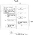
- Fig. 2 is a diagram showing an overall configuration of a printing system according to the first embodiment of the present invention.
- the printing system includes: a print data generation apparatus 100 that generates print data by performing various processes on submitted data such as a PDF file; a plate making apparatus 200 that produces a printing plate on the basis of the print data; a printing apparatus 300 that performs printing using the printing plate manufactured by the plate making apparatus 200; a digital printing apparatus 400 such as an inkjet printer or copier that performs printing on the basis of the print data which is digital data without using the printing plate; and a colorimeter 500 for measuring a color.
- the print data generation apparatus 100, the plate making apparatus 200, the digital printing apparatus 400, and the colorimeter 500 are communicably interconnected by a communication line 600. Note that the colorimeter 500 used in the present embodiment is a spectral colorimeter.
- a color prediction model that is a model (learning model) for predicting a color of a patch to be included in the CxF chart is constructed.
- this color prediction model also for a spot color for which the CxF chart is not printed, color values (spectral reflectances) of each patch when the CxF chart is assumed to be printed can be obtained.
- the print data generation apparatus 100 also generates print data for creating a CxF chart necessary for constructing such a color prediction model.
- the print data generation apparatus 100 also performs an overprint prediction process for predicting a color obtained by overprinting inks of a plurality of colors (typically, a color of a portion where a plurality of spot color inks are overprinted or a portion where a spot color ink and a process color ink are overprinted).
- an overprint prediction process prediction results (predicted values of spectral reflectances) by a color prediction model are used as necessary.
- the print data generation apparatus 100 also performs a process for converting the data obtained by the overprint prediction process into print data in a format that can be printed by the digital printing apparatus 400. It should be noted that, as a specific method of the overprint prediction process, the above-described Deshpande et al. method may be employed, or another method may be employed.
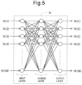
- Fig. 3 is a diagram showing a hardware configuration of the print data generation apparatus 100 in the present embodiment.
- the print data generation apparatus 100 is implemented by a personal computer, and includes a CPU 11, a ROM 12, a RAM 13, an auxiliary storage device 14, an input operation unit 15 such as a keyboard, a display unit 16, an optical disk drive 17, and a network interface unit 18.
- the submitted data transmitted through the communication line 600 is inputted into the print data generation apparatus 100 via the network interface unit 18.
- Print data generated by the print data generation apparatus 100 is sent to the digital printing apparatus 400 through the communication line 600 via the network interface unit 18.
- a program 141 for constructing the color prediction model (hereinafter referred to as a "color prediction model construction program") is stored in the auxiliary storage device 14.
- the color prediction model construction program 141 is provided by being stored in a computer readable recording medium such as a CD-ROM or a DVD-ROM. That is, a user purchases, for example, an optical disk (CD-ROM, DVD-ROM, etc.) 170 as a recording medium for the color prediction model construction program 141, mounts the optical disk 170 on the optical disk drive 17, reads the color prediction model construction program 141 from the optical disk 170, and installs the read program in the auxiliary storage device 14.
- the color prediction model construction program 141 sent through the communication line 600 may be received by the network interface unit 18 and installed in the auxiliary storage device 14.
- a GPU may be provided as a processor instead of the CPU 11, or the CPU 11 and the GPU may be provided as processors.
- the spectral reflectances can be obtained relatively easily for the solid patch PA2 and the paper white patch PA1 among the 22 patches constituting the CxF chart. Further, as long as the same paper is used as the base material when performing printing, each of the spectral reflectances of the paper white patch PA1 is constant regardless of an ink color. Therefore, in the present embodiment, a color prediction model for predicting the spectral reflectances of each of the color prediction target patches (the patches excluding the solid patch PA2 and the paper white patch PA1 from the 22 patches constituting the CxF chart) on the basis of the spectral reflectances of the solid patch PA2 is constructed.
- the spectral reflectances of each of the color prediction target patches for the color prediction target ink are predicted.
- a patch based on which the spectral reflectances of each of the color prediction target patches are predicted such as the solid patch PA2 in the present embodiment, is referred to as a "reference patch”.
- the color prediction model is implemented by a neural network 73 that performs machine learning (see Fig. 4 ).
- the color prediction process is roughly classified into a learning stage process and a prediction (inference) stage process.
- teaching data is given to the neural network 73, and machine learning using the teaching data is performed in the neural network 73.
- the neural network 73 is given, as teaching data, spectral reflectances obtained by colorimetry of the patches in the CxF chart.
- teaching data spectral reflectances obtained by colorimetry of the patches in the CxF chart.
- one piece of teaching data is composed of 36 spectral reflectances obtained by colorimetry of the solid patch PA2 and 36 spectral reflectances obtained by colorimetry of one color prediction target patch.
- the spectral reflectances of the solid patch (reference patch) PA2 for the color prediction target ink are given to the learned neural network 73.
- the spectral reflectances (predicted values) of the color prediction target patch for the color prediction target ink are outputted from the neural network 73.
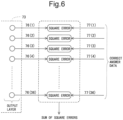
- Fig. 5 is a diagram showing an example of the structure of the neural network 73 used in the present embodiment.
- the neural network 73 includes an input layer, a hidden layer (intermediate layer), and an output layer.
- the input layer is composed of 36 units (neurons) that receive 36 spectral reflectances 75(1) to 75(36).
- the hidden layer is also composed of 36 units. Note that the number of units in the hidden layer is not limited to 36. In addition, although the number of hidden layers is 1 in the example shown in Fig. 5 , the number of hidden layers may be 2 or more.
- the output layer is composed of 36 units that output 36 spectral reflectances 76(1) to 76(36).
- the input layer and the hidden layer are fully connected, and the hidden layer and the output layer are also fully connected.
- a sigmoid function is adopted as the activation function for the hidden layer and the output layer.
- a function other than the sigmoid function may be adopted as the activation function.
- the spectral reflectances 75(1) to 75(36) are given to the input layer.
- forward propagation processing is performed in the neural network 73, and the sum of square errors of the spectral reflectances 76(1) to 76(36) outputted from the output layer and the spectral reflectances 77(1) to 77(36) which are correct answer data is obtained (see Fig. 6 ).
- the parameters (weighting coefficients, biases) of the neural network 73 are updated by using the gradient descent method on the basis of the result obtained by the back propagation processing of the errors.
- the above parameters are optimized by repeating the learning as described above.
- batch learning may be used in which all pieces of teaching data are given to the neural network 73 in a collective manner
- mini-batch learning may be used in which teaching data is divided into a plurality of group, and the teaching data is given to the neural network 73 for each group
- online learning may be used in which teaching data is given to the neural network 73 one by one.
- the spectral reflectances 75(1) to 75(36) of the solid patch PA2 for the color prediction target ink are given to the input layer.
- the spectral reflectances 76(1) to 76(36) outputted from the output layer by the forward propagation processing in the neural network 73 are treated as the predicted values of the spectral reflectances of the color prediction target patch for the color prediction target ink.
- the neural network 73 shown in Fig. 5 is prepared for each color prediction target patch.
- 20 patches are taken as color prediction target patches
- 20 neural networks 73(1) to 73(20) are prepared as shown in Fig. 7 .
- learning and prediction (inference) are performed for each color prediction target patch using the corresponding neural network 73.
- step S100 a process of acquiring teaching data necessary for learning in the neural network 73 to be constructed as a color prediction model is performed (step S100).
- step S100 it is preferable to acquire a sufficient number of teaching data pieces so that spectral reflectances are accurately predicted.
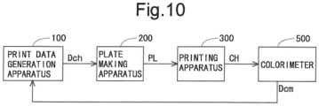
- the step S100 includes a step of printing a CxF chart (step S102) and a step of measuring spectral reflectances (step S104). The processes in the step S102 and the step S104 will be described in detail with reference to Fig. 10 .
- step S102 first, print data Dch for outputting the CxF chart is created by the print data generation apparatus 100, and the print data Dch is sent to the plate making apparatus 200.
- the plate making apparatus 200 produces a printing plate PL on the basis of the print data Dch.
- the printing apparatus 300 performs printing using the printing plate PL.
- the CxF chart CH is outputted from the printing apparatus 300.
- the colorimeter 500 performs colorimetry of the patches included in the CxF chart CH printed in the step S102.
- Colorimetric data Dcm obtained by the colorimetry by the colorimeter 500 is sent to the print data generation apparatus 100.
- the colorimeter 500 used in the present embodiment is a spectral colorimeter. Therefore, the colorimetric data Dcm obtained by the colorimetry is spectral reflectance data.
- spectral reflectance data is obtained in 10 nm increments in the wavelength range of 380 to 730 nm. Accordingly, 36 pieces of spectral reflectance data are obtained by performing the colorimetry of any one of the patches in the CxF chart CH.
- step S110 machine learning using the teaching data obtained in the step S100 is performed by the neural network 73 (step S110). As described above, in the present embodiment, this machine learning is performed using the corresponding neural network 73 for each color prediction target patch.
- the parameters (weighting coefficients, biases) of the neural network 73 are optimized.
- the neural network 73 having the optimized parameters serves as a color prediction model used for color prediction. In this manner, in the step S110, a color prediction model for predicting the color of a patch in the CxF chart is constructed.
- step S100 and the step S110 need to be performed only once, and do not need to be performed for each process for one color prediction target ink.
- the processes in the step S120 and the step S130 need to be performed for each process for one color prediction target ink.
- the spectral reflectances of the solid patch PA2 for the color prediction target ink are measured using the colorimeter 500.
- the spectral reflectances of the solid patch can be obtained, for example, by performing colorimetry of a portion of the corresponding color included in a colored ball or printed matter. Further, the spectral reflectances of the solid patch can be substituted with the spectral reflectances of the color sample of the corresponding color.
- the spectral reflectances (predicted values) of the color prediction target patch for the color prediction target ink are obtained by giving, as input data, the spectral reflectances obtained in the step S120 to the neural network 73 serving as the color prediction model constructed in the step S110 (step S130).
- step S130 36 spectral reflectances are obtained for each of the 20 color prediction target patches.
- the spectral reflectances of the solid patch PA2 have been obtained in the step S120.
- past measured values can be used as long as the same paper is used. Thus, even if the CxF chart for the color prediction target ink is not actually printed, the spectral reflectances of all patches when the CxF chart is assumed to be printed can be obtained.
- a teaching data acquisition step is implemented by the step S100
- a learning step is implemented by the step S110
- a second spectral characteristic measurement step is implemented by the step S120
- a spectral characteristic prediction step is implemented by the step S130.
- a color chart printing step is implemented by the step S102
- a first spectral characteristic measurement step is implemented by the step S104.
- Fig. 11 is a graph showing experimental results for the first type patches 71.
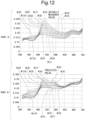
- Fig. 12 is a graph showing experimental results for the second type patches 72.
- part A represents actually measured values of reflectances at respective wavelengths by a solid lines for respective patches
- part B represents predicted reflectance values of reflectances at respective wavelengths by solid lines for respective patches.
- the horizontal axis represents wavelength (unit: nm)
- the vertical axis represents reflectance.
- the correspondence relationship between reference signs and dot percentages of the spot color in the CxF chart is as follows: "M(0): 0%, M(1): 10%, M(2): 20%, M(3): 30%, M(4): 40%, M(5): 50%, M(6): 60%, M(7): 70%, M(8): 80%, M(9 ): 90%, and M(10): 100%".
- the prediction is performed with sufficient accuracy as a whole, although the prediction accuracy for halftone is slightly low.
- the spectral reflectance of each of the halftone patches can also be obtained by performing interpolation calculation on the basis of the spectral reflectance of the paper white patch PA1 and the spectral reflectance of the solid patch PA2.
- the reflectance is higher as the density of the spot color is lower in the wavelength region of about 480 nm or less, whereas the reflectance is higher as the density of the spot color is higher in the wavelength region of about 480 nm or more.
- the reflectance generally decreases as inks are more overlaid.
- the reflectance increases as inks are more overlaid. This is presumably because an opaque component is present in the spot color ink and light is reflected at the opaque portion.
- the color difference (that is, the prediction error) between the actually measured value and the predicted value is around 5 regardless of the density of the spot color.
- the color difference is obtained as follows. First, tristimulus values X, Y, and Z are obtained for each of the actually measured value and the predicted value from the spectral reflectance using a predetermined equation. Next, for each of the actually measured value and the predicted value, Lab values ("L value”, “a value”, and “b value”) are obtained from the tristimulus values X, Y, and Z by a predetermined conversion equation. Next, for each of "L value”, "a value”, and "b value”, the difference between the actually measured value and the predicted value is obtained.
- the value (positive value) of the square root of the sum of squares of the three differences obtained in this manner is the color difference. It is supposed here that the spectral reflectances of all the second type patches 72 are substituted with the spectral reflectances of the black solid patch PA3, on the assumption that the spectral reflectances of the black solid patch PA3 can be obtained. In this case, the patch having a higher density of the spot color has a greater color difference. At the patch in which a dot percentage of the spot color is 100 % among the second type patches 72, the color difference is about 13. Since the color difference is about 5 regardless of the density of the spot color in a case in which the prediction is performed using the neural network 73 according to the present embodiment, the superiority of the method of the present embodiment can be understood.
- the CxF chart (see Fig. 1 ) used for predicting a color obtained by overprinting inks of a plurality of colors
- patches other than the solid patch PA2 and the paper white patch PA1 are taken as color prediction target patches, and the relationship between the spectral reflectances of the solid patch PA2 and the spectral reflectances of each of the color prediction target patches is learned by the neural network 73.
- a color prediction model for predicting a color of the patch to be included in the CxF chart is constructed.
- the spectral reflectances (predicted values) of each of the color prediction target patches for the color prediction target ink are obtained.
- the spectral reflectances of respective patches when the CxF chart is assumed to be printed can be obtained without printing the CxF chart for the color prediction target ink. Therefore, printing of the CxF chart and colorimetry thereof are not necessary. From the above, it is possible to predict the color obtained by overprinting inks of a plurality of colors at lower cost and with fewer man-hours than ever before.
- the spectral reflectances of the color prediction target patch are predicted on the basis of the spectral reflectances of the solid patch PA2.
- the present invention is not limited thereto, and the spectral reflectances of the color prediction target patch may be predicted on the basis of the spectral reflectances of the solid patch PA2 and the spectral reflectances of the paper white patch PA1.
- the neural network 73 has a structure shown in Fig. 13 , for example.
- an input layer is composed of 72 units that receive 36 spectral reflectances 75(1) to 75(36) of the solid patch PA2 and 36 spectral reflectances 78(1) to 78(36) of the paper white patch PA1.
- a hidden layer is composed of, for example, 36 units.
- an output layer is composed of 36 units that output 36 spectral reflectances 76(1) to 76(36) of the color prediction target patch.
- the spectral reflectances 78(1) to 78(36) of the paper white patch PA1 as well as the spectral reflectances 75(1) to 75(36) of the solid patch PA2 are given to the neural network 73 as input data.
- learning by the neural network 73 is performed taking the characteristics of the base material (printing paper) used for printing into account. Therefore, the spectral reflectances when printing is performed on the corresponding base material can be predicted with higher accuracy.
- the spectral reflectances of the color prediction target patch may be predicted on the basis of the spectral reflectances of the solid patch PA2 and the spectral reflectances of the black solid patch PA3.
- a neural network 73 having the same structure as that of the first modification is used, and when performing learning and when performing prediction, 36 spectral reflectances of the solid patch PA2 and 36 spectral reflectances of the black solid patch PA3 are given to the neural network 73 as input data.
- the neural network 73 is directly given the spectral reflectance values as input data.
- the present invention is not limited thereto.
- the configuration may be such that measured values of spectral reflectances are subjected to normalization with the spectral reflectance of the paper white patch PA1 being 1 and the values obtained by normalization are given to the neural network 73 as input data.
- the same number of neural networks 73 as the number of the color prediction target patches are prepared, and learning and prediction (inference) are performed for each color prediction target patch using the corresponding neural network 73.
- the present invention is not limited thereto.
- the configuration may be such that all the color prediction target patches are processed by one neural network 73.
- Fig. 14 is a diagram showing an example of the structure of a neural network 73 in this modification. It should be noted that, in Fig. 14 , lines indicating connection between two layers are not illustrated. An input layer and a hidden layer are fully connected, and the hidden layer and an output layer are also fully connected. The input layer and the hidden layer have the same structure as that of the first embodiment.
- the output layer is configured to output 36 spectral reflectances 76(1) to 76(36) of all the color prediction target patches. That is, in the output layer, 36 units that output 36 spectral reflectances 76(1) to 76(36) are provided for each of the 20 color prediction target patches P(1) to P(20).
- the network between the input layer and the hidden layer is shared by all color prediction target patches.
- the overall processing speed is increased as compared with the first embodiment.
- the spectral reflectances of the color prediction target patch are predicted on the basis of the spectral reflectances of the solid patch PA2. That is, the spectral reflectances are predicted using the solid patch PA2 as a reference patch.
- the present invention is not limited thereto, and the configuration may be such that, on the basis of the spectral reflectances of a halftone patch, the spectral reflectances of the other patches (color prediction target patches) are predicted.
- the present invention can also be configured such that the relationship between the spectral reflectances of the patch in which a dot percentage of the spot color is 50% among the first type patches 71 and the spectral reflectances of the other patches is learned by the neural network 73, and by giving the spectral reflectances in the state in which the color prediction target ink is applied at a dot percentage of 50% on the base material to the learned neural network 73, the spectral reflectances (predicted values) of the color prediction target patch for the color prediction target ink are obtained. In this way, the spectral reflectances may be predicted using a halftone patch as a reference patch.
- the first embodiment describes an example in which the CxF chart including the first type patches 71 and the second type patches 72 is used.
- a CxF chart having three parts as schematically shown in Fig. 15 may be used.
- Each of the patches in the part denoted by reference numeral 81 in Fig. 15 is a first type patch.
- Each of the patches in the part denoted by reference numeral 82 in Fig. 15 is a second type patch.
- Each of the patches in the part denoted by reference numeral 83 in Fig. 15 is a patch (hereinafter referred to as a "third type patch") obtained by printing a target ink on black at a dot percentage of 500.
- the spectral reflectances of each of the third type patches 83 for the color prediction target ink can also be predicted by the learned neural network 73.
- the relationship between the spectral reflectances of the solid patch PA2 (see Fig. 1 ) and the spectral reflectances of the color prediction target patch is learned in advance by the neural network 73.
- the relationship between the spectral reflectances of the solid patch PA2 and the tone values (tone levels) of the color prediction target patch is learned in advance by the neural network 73. That is, the tone values are outputted from an output layer of the neural network 73.
- the tone values (predicted values) of the color prediction target patch are obtained by giving the spectral reflectances of the solid patch PA2 for the color prediction target ink to the learned neural network 73. Then, the spectral reflectances are calculated from the tone values on the basis of a predetermined conversion equation.
- tone values are predicted using the neural network 73.
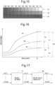
- the tone values will be described with reference to Fig. 16 .
- the horizontal axis represents wavelength
- the vertical axis represents reflectance.
- a curve denoted by reference numeral 84 represents the reflectances at respective wavelengths regarding the color of the base material itself (paper white).
- a curve denoted by reference numeral 85 represents the reflectances at respective wavelengths in a state in which a certain ink is solidly applied on the base material (at a dot percentage of 100%).
- a curve denoted by reference numeral 86 represents the reflectances at respective wavelengths in a state in which the certain ink is applied on the base material at a certain dot percentage (here, at a dot percentage of Q%).
- the tone value TV at the wavelength W in a state in which the certain ink is applied on the base material at a dot percentage of Q% is expressed by the following Equation (4) (see Fig. 16 ).
- Equation (5) V 3 ⁇ TV V 3 ⁇ V 4
- tone values 87(1) to 87(36) of the color prediction target patch for the color prediction target ink are outputted from the neural network 73 as shown in Fig. 17 .
- a color value converter 88 for converting the tone values 87(1) to 87(36) into spectral reflectances 76(1) to 76(36) is provided as shown in Fig. 17 .
- the color value converter 88 converts the tone values 87(1) to 87(36) into spectral reflectances 76(1) to 76(36) using the above Equation (5).
- the spectral reflectance of the paper white patch is substituted for V3 in the above Equation (5), and the spectral reflectance of the solid patch is substituted for V4 in the above Equation (5).
- step S200 a process of acquiring teaching data necessary for learning by the neural network 73 is performed.
- the step S200 includes a step of printing a CxF chart (step S202), a step of measuring spectral reflectances (step S204), and a step of converting spectral reflectances into tone values (step S206).
- step S202 the CxF chart is printed in the same manner as in the first embodiment.
- step S204 the spectral reflectances are measured in the same manner as in the first embodiment.
- step S206 a process for converting the spectral reflectances obtained in the step S204 into tone values is performed using the above Equation (4).
- one piece of teaching data is composed of 36 spectral reflectances obtained by colorimetry of the solid patch PA2 and 36 tone values corresponding to 36 spectral reflectances obtained by colorimetry of one color prediction target patch.
- step S210 After acquiring the teaching data, machine learning using the teaching data obtained in the step S200 is performed by the neural network 73 (step S210).
- the parameters (weighting coefficients, biases) of the neural network 73 are optimized, and a color prediction model for predicting a color of the patch in the CxF chart is constructed.
- step S220 spectral reflectances of the solid patch PA2 for the color prediction target ink are measured using the colorimeter 500 as in the first embodiment. Then, tone values (predicted values) of the color prediction target patch for the color prediction target ink are obtained by giving, as input data, the spectral reflectances obtained in the step S220 to the neural network 73 serving as the color prediction model constructed in the step S210 (step S230). In the step S230, 36 tone values are obtained for each of the 20 color prediction target patches. Finally, spectral reflectances are calculated from the tone values obtained in the step S230 on the basis of the above Equation (5) (step S240).
- a teaching data acquisition step is implemented by the step S200
- a learning step is implemented by the step S210
- a second spectral characteristic measurement step is implemented by step the S220
- a tone level prediction step is implemented by step the S230
- a spectral characteristic calculation step is implemented by the step S240.
- a color chart printing step is implemented by the step S202
- a first spectral characteristic measurement step is implemented by the step S204
- a color value conversion step is implemented by the step S206.
- the color prediction model is constructed after spectral reflectances are obtained by colorimetry of the patches in the color chart by the colorimeter 500.
- a color prediction model can also be constructed on the basis of measured values other than spectral reflectances.
- a color prediction model can also be constructed on the basis of spectral absorption factors (values each obtained by subtracting the spectral reflectance from 1) or spectral absorption coefficients ⁇ each obtained from the following Equation (6). Note that measured values such as spectral reflectances, spectral absorption factors, and spectral absorption coefficients correspond to "spectral characteristics".
- a color prediction model is constructed using the CxF chart shown in Fig. 1 (CxF chart including the first type patch 71 and the second type patch 72) in the first embodiment (including modifications other than the sixth modification) and the second embodiment, and a color prediction model is constructed using the CxF chart shown in Fig. 15 (CxF chart including the first type patch 81, the second type patch 82, and the third type patch 83) in the sixth modification of the first embodiment.
Landscapes
- Engineering & Computer Science (AREA)
- Multimedia (AREA)
- Signal Processing (AREA)
- Color Image Communication Systems (AREA)
- Spectrometry And Color Measurement (AREA)
- Facsimile Image Signal Circuits (AREA)
Description
- The present invention relates to a method for constructing a color prediction model for predicting a color of a patch in a color chart used for predicting a color obtained by overprinting inks of a plurality of colors (typically, a plurality of colors including a spot color).
- In recent years, digital printing apparatuses have become popular in the printing industry. However, in the labeling and packaging field, printing (offset printing, gravure printing, flexographic printing, etc.) with printing apparatuses using printing plates (hereinafter referred to as a "conventional printing apparatus" or simply referred to as a "printing apparatus") is still often performed in recent years. Meanwhile, there is an increasing demand for quick delivery for design and content production, and when there are some changes in design or the like in a case in which a conventional printing apparatus is used, cost for recreation of the printing plate or retrogression of the process is high, which is a significant problem. In this respect, a digital printing apparatus does not use a printing plate, and thus, does not need an operation for exchanging or recreating the printing plate. That is, by adopting a digital printing apparatus, it is possible to carry out especially small-lot printing at low cost, and therefore, it is also possible to respond to the demand of quick delivery for design and content production at low cost.
- Meanwhile, in the labeling and packaging field, spot colors tend to be often used for enhancing color expression. For this reason, in order to perform printing with a digital printing apparatus using print data generated for printing with a conventional printing apparatus, it is necessary that colors obtained by overprinting spot color inks be predicted and the predicted colors be reproduced with the digital printing apparatus. In the following, prediction values of values (specifically, reflectance or tristimulus values X, Y, and Z in the CIE 1931 XYZ color space) identifying colors obtained by overprinting inks of a plurality of colors is referred to as an "overprint prediction value".
- The "Recommendations for predicting spot color overprints" (http://www.color.org/ICC_white_paper_43_Draft2kd.doc) by K. Deshpande and P. Green discloses a method (hereinafter, referred to as "Deshpande et al. method") for relatively easily predicting colors (overprint prediction values) obtained by overprinting inks of a plurality of colors including a spot color. In the Deshpande et al. method, overprint prediction values are expressed as in the following Equations (1) to (3) using tristimulus values X, Y, and Z (see
Fig. 20 ).


- Here, Xb, Yb, and Zb are tristimulus values of a background color, Xf, Yf, and Zf are tristimulus values of a foreground color, jx, jy, and jz are scaling coefficients, and kx, ky, and kz are constants. Hereinafter, jx, jy, jz, kx, ky, and kz are collectively referred to as "overprint coefficient".
- Meanwhile, color reproduction methods include additive color mixing and subtractive color mixing. In the case of printing, the subtractive color mixing is applied for color reproduction. In this regard, if ideal subtractive color mixing is performed, the stimulus value X of the color obtained by overprinting is represented by "Xb × Xf" (the same applies to the stimulus values Y and Z), for example. However, in order to obtain a more accurate value, it is necessary to make a correction in consideration of an error caused by the use of an opaque ink and reflection of light on the surface. Therefore, in the Deshpande et al. method, a correction using a linear equation is performed as shown in the above Equations (1) to (3).
- In the Deshpande et al. method, a color chart as schematically shown in
Fig. 21 is used, for example. This color chart is called a "CxF chart". In the example shown inFig. 21 , the CxF chart is composed of twenty-two patches. The eleven patches in the upper part are patches obtained by printing an ink of a target spot color on a base material such as paper at a dot percentage in increments of 10%. The eleven patches in the lower part are patches obtained by printing an ink of a target spot color on black (black solid) at a dot percentage in increments of 10%. The overprint prediction value is calculated using the value (colorimetry value) obtained by the colorimetry of the patches in the CxF chart described above. - Hereinafter, the Deshpande et al. method will be described in detail with reference to the flowchart in
Fig. 22 , taking, as an example, calculation of an overprint prediction value in the case where a background color is a spot color at a dot percentage of 40% (referred to as a "spot color 1" for convenience) and a foreground color is another spot color at a dot percentage of 60% (referred to as a "spot color 2" for convenience). - First, the CxF chart is printed using the ink of
spot color 1, and further, the CxF chart is printed using the ink of spot color 2 (step S900). - Next, the overprint coefficients jx, jy, jz, kx, ky, and kz of the above Equations (1) to (3) regarding the
spot color 2 are calculated using the CxF chart printed using the ink of spot color 2 (referred to as "spot color 2 chart" for convenience) (step S910). In this regard, focusing on the above Equation (1), for example, the practical maximum value and the minimum value for Xb × Xf are values obtained by the ink of thespot color 2 being applied on the base material and black (black solid), respectively. The same applies to Yb × Yf and Zb × Zf. Therefore, in order to calculate the overprint coefficient, in a coordinate system representing the above Equations (1) to (3) (seeFig. 23 . Note thatFig. 23 shows only the coordinate system representing the above Equation (1)), the coordinates representing the stimulus value of a state where the ink of thespot color 2 at a dot percentage of 60% is applied on black are defined as a first calibration point P91, and the coordinates representing the stimulus value of a state where the ink of thespot color 2 at a dot percentage of 60% is applied on the base material are defined as a second calibration point P92. - Focusing on, for example, X among the tristimulus values, values are assigned as follows for the first calibration point P91 with respect to the above Equation (1). The value obtained by colorimetry of the patch PA93 in the
spot color 2 chart (black stimulus value) is assigned to Xb, the value obtained by colorimetry of the patch PA92 in thespot color 2 chart (stimulus value of a state where the ink of thespot color 2 at a dot percentage of 60% is applied on the base material) is assigned to Xf, and the value obtained by colorimetry of the patch PA91 in thespot color 2 chart (stimulus value of a state where the ink of thespot color 2 at a dot percentage of 60% is applied on black) is assigned to X (seeFig. 21 ). In addition, for the second calibration point P92, values are assigned as follows with respect to the above Equation (1). The value obtained by colorimetry of the patch PA94 in thespot color 2 chart (stimulus value of base material) is assigned to Xb, the value obtained by colorimetry of the patch PA92 in thespot color 2 chart (stimulus value of a state where the ink of thespot color 2 at a dot percentage of 60% is applied on the base material) is assigned to Xf and X (seeFig. 21 ). - The overprint coefficients jx and kx are calculated by solving a simultaneous equation consisting of the equation relating to the first calibration point P91 and the equation relating to the second calibration point P92. That is, an equation representing a straight line denoted by reference numeral L91 in
Fig. 23 is obtained. The overprint coefficients jy, jz, ky, and kz are similarly calculated. - Although the patches are provided in 10% increments in the CxF chart shown in
Fig. 21 , an overprint coefficient corresponding to the dot percentage between two patches which are adjacent to each other in the horizontal direction can be obtained on the basis of the colorimetric values obtained by linear interpolation. - Next, the values of Xb, Yb, and Zb (tristimulus values of the background color) for calculating final overprint prediction values in the above Equations (1) to (3) are obtained using the CxF chart printed using the ink of spot color 1 (referred to as "
spot color 1 chart" for convenience) (step S920). Specifically, the values of Xb, Yb, and Zb are obtained by colorimetry of the patch PA95 (seeFig. 21 ) in thespot color 1 chart. - Next, the values of Xf, Yf, and Zf (tristimulus values of the foreground color) for calculating the final overprint prediction values in the above Equations (1) to (3) are obtained using the
spot color 2 chart (step S930). Specifically, the values of Xf, Yf, and Zf are obtained by colorimetry of the patch PA92 (seeFig. 21 ) in thespot color 2 chart. - Finally, the values obtained in steps S910 to S930 are substituted into the above Equations (1) to (3), whereby the tristimulus values X, Y, and Z as overprint prediction values are calculated (step S940). This corresponds to, for example, calculating, as the value of X, the ordinate value of the straight line L91 in
Fig. 23 when the abscissa indicates the product of "Xb calculated in step S920" and "Xf calculated in step S930". - In the above description, the values of X, Xf, and Xb relating to the first calibration point P91 (see
Fig. 23 ) are obtained by colorimetry of the patches PA91, PA92, and PA93 in thespot color 2 chart. However, if a highly accurate overprint prediction value is not necessary, the first calibration point P91 can be regarded as being located at the origin of the graph inFig. 23 for simplicity. In this case, the colorimetry of the patches PA91 and PA93 in thespot color 2 chart is not necessary (the colorimetry of the patch PA92 is still necessary for obtaining the values of X and Xf of the second calibration point P92). In this case, the tristimulus values X, Y, and Z as the overprint prediction values can be calculated without printing the lower patch group including the patches PA91 and PA93 in the CxF chart shown inFig. 21 . The CxF chart having the upper patch group shown inFig. 21 without having the lower patch group is herein referred to as a "simple CxF chart" for convenience. - It should be noted that, in relation to the present invention,
Japanese Laid-Open Patent Publication No. 6-281501 - As described above, according to the Deshpande et al. method, color prediction is performed using, for example, a CxF chart as shown in
Fig. 21 . However, even when printing using spot colors is performed, such a CxF chart is usually not printed in advance. For this reason, it is necessary to print the same number of CxF charts as the number of the spot colors and perform colorimetry of the respective patches. This causes an increase in cost and man-hours. - Moreover, the prior art document
US 2010/0091305 A1 discloses a system and a method for printing target colors with process colors utilizing parallel feedforward neural networks. In particular, according toUS 2010/0091305 A1 , a system for printing target colors includes a print-engine interface and a neural network component. The print-engine interface is in operative communication with a print engine of a printing system. The neural network component is calibrated to the print engine for printing a target color on a substrate. The neural network is in operative communication with the print-engine interface and communicates a parameter associated with printing the target color on the substrate utilizing the print engine. - In view of the above, an object of the present invention is to enable prediction of a color of a patch to be included in a CxF chart so that a color obtained by overprinting inks of a plurality of colors can be predicted at lower cost and with fewer man-hours than ever before. This object is achieved by the subject-matters of the
claims claims - One aspect of the present invention is directed to a color prediction model construction method for constructing a color prediction model for predicting a color of a patch in a color chart including a plurality of first type patches obtained by applying an ink on a base material with ink densities of a plurality of levels, the color prediction model construction method including:
- a teaching data acquisition step (S100, S200) of acquiring a plurality of pieces of teaching data including spectral characteristics of a reference patch that is a prescribed patch in the color chart and color values of a color prediction target patch in the color chart; and
- a learning step (S110, S210) of performing machine learning by a neural network that takes the spectral characteristics of the reference patch as input data and takes the color values of the color prediction target patch as output data, using the plurality of pieces of teaching data.
- According to such a configuration, regarding the color chart used for predicting a color obtained by overprinting inks of a plurality of colors, the relationship between the spectral characteristics of the reference patch and the color values of the color prediction target patch is learned by a neural network. Thus, a color prediction model for predicting a color of a patch to be included in the color chart is constructed. By using the constructed color prediction model, it is possible to obtain the spectral characteristics of respective patches when a color chart for color prediction target ink is assumed to be printed, without printing the color chart and performing colorimetry. From the above, it is possible to predict the color obtained by overprinting inks of a plurality of colors at lower cost and with fewer man-hours than ever before.
- Another aspect of the present invention is directed to a color prediction model construction program for constructing a color prediction model for predicting a color of a patch in a color chart including a plurality of first type patches obtained by applying an ink on a base material with ink densities of a plurality of levels, the color prediction model construction program causing a computer to execute:
- a teaching data reading step (S100, S200) of reading a plurality of pieces of teaching data including spectral characteristics of a reference patch that is a prescribed patch in the color chart and color values of a color prediction target patch in the color chart; and
- a learning step (S110, S210) of performing machine learning by a neural network that takes the spectral characteristics of the reference patch as input data and takes the color values of the color prediction target patch as output data, using the plurality of pieces of teaching data.
- These and other objects, features, modes, and advantageous effects of the present invention will become more apparent from the following detailed description of the present invention with reference to the accompanying drawings.
-
-
Fig. 1 is a diagram for describing terms regarding a CxF chart used herein. -
Fig. 2 is a diagram showing an overall configuration of a printing system according to a first embodiment of the present invention. -
Fig. 3 is a diagram showing a hardware configuration of a print data generation apparatus in the first embodiment. -
Fig. 4 is a diagram for describing an overview of a color prediction process in the first embodiment. -
Fig. 5 is a diagram showing an example of the structure of a neural network in the first embodiment. -
Fig. 6 is a diagram for describing a process during learning using the neural network in the first embodiment. -
Fig. 7 is a diagram for describing that the neural network is prepared for each color prediction target patch in the first embodiment. -
Fig. 8 is a flowchart showing a procedure of the color prediction process in the first embodiment. -
Fig. 9 is a flowchart showing a procedure of acquiring teaching data in the first embodiment. -
Fig. 10 is a block diagram for describing details of acquisition of the teaching data in the first embodiment. -
Fig. 11 is a graph showing experimental results about a first type patch regarding the first embodiment. -
Fig. 12 is a graph showing experimental results about a second type patch regarding the first embodiment. -
Fig. 13 is a diagram showing an example of the structure of a neural network in a first modification of the first embodiment. -
Fig. 14 is a diagram showing an example of the structure of a neural network in a fourth modification of the first embodiment. -
Fig. 15 is a diagram schematically showing an example of a CxF chart used in a sixth modification of the first embodiment. -
Fig. 16 is a diagram for describing a tone value in a second embodiment of the present invention. -
Fig. 17 is a block diagram for describing a color prediction process in the second embodiment. -
Fig. 18 is a flowchart showing a procedure of the color prediction process in the second embodiment. -
Fig. 19 is a flowchart showing a procedure of acquiring teaching data in the second embodiment. -
Fig. 20 is a diagram for describing a Deshpande et al. method in relation to a conventional example. -
Fig. 21 is a diagram schematically showing an example of a CxF chart in relation to the conventional example. -
Fig. 22 is a flowchart for describing the Deshpande et al. method in relation to the conventional example. -
Fig. 23 is a diagram for describing the Deshpande et al. method in relation to the conventional example. - Prior to describing embodiments, the concept of the present invention will be described. It should be noted that, in the following, each of upper patches in the CxF chart (each of patches in the part denoted by
reference numeral 71 inFig. 1 ) (a patch obtained by printing a target ink on a base material) is referred to as a "first type patch", and each of lower patches in the CxF chart (each of patches in the part denoted byreference numeral 72 inFig. 1 ) (a patch obtained by printing a target ink on black) is referred to as a "second type patch". Also, a patch representing the color of the base material itself (a patch marked with PA1 inFig. 1 ) is referred to as a "paper white patch", a patch obtained by solidly applying the target ink all over the base material (at a dot percentage of 100%) (a patch marked with PA2 inFig. 1 ) is referred to as a "solid patch", and a patch obtained by solidly applying only a black ink all over the base material (a patch marked with PA3 inFig. 1 ) is referred to as a "black solid patch". - As described above, the colorimetry result (colorimetric value) of the CxF chart is required to predict a color obtained by overprinting a plurality of color inks including a spot color ink. In this regard, spectral reflectances which are colorimetric values can be relatively easily obtained for the solid patch PA2 and the paper white patch PA1 among 22 patches constituting the CxF chart. It should be noted that, in the following embodiments, the spectral reflectances are obtained in 10 nm increments in the wavelength range of 380 to 730 nm. However, it is not limited thereto. For example, the spectral reflectances may be obtained in increments of a unit wavelength range of an appropriate size (for example, in 10 nm increments) in the wavelength range of 400 to 700 nm. That is, one color is specified by spectral reflectances, the number of the spectral reflectances (for example, 36) is obtained by dividing the wavelength range by the unit wavelength range.
- The spectral reflectances of the solid patch PA2 can be obtained, for example, by performing colorimetry of a portion of the corresponding color included in a colored ball or printed matter. Further, the spectral reflectances of the solid patch PA2 can be substituted with the spectral reflectances obtained by colorimetry of the color sample of the corresponding color. This is because the color sample represents a target color when the corresponding color is solidly applied.
- The spectral reflectances of the paper white patch PA1 are obtained by colorimetry of a portion on the base material where nothing is printed. Further, as long as the same paper is used as the base material when performing printing, each of the spectral reflectances of the paper white patch PA1 is constant regardless of an ink color. Therefore, even when processing is performed for a plurality of color inks, the spectral reflectances of the paper white patch PA1 needs to be measured only once, as long as the same paper is used. Note that the configuration may be such that spectral reflectances of the paper white patches PA1 of a plurality of CxF charts are measured and the average values thereof are used as the representative values of the respective spectral reflectances of the paper white patch PA1.
- Regarding 20 patches among 22 patches constituting the CxF chart except for the solid patch PA2 and the paper white patch PA1, the accurate spectral reflectances cannot be obtained unless the colorimetry of the matter actually printed on the base material or black is performed. However, focusing on a plurality of spot colors having similar colors, in regard to each of the 20 patches described above, the respective spectral reflectances for the plurality of spot colors are considered to be close to each other. As long as the same paper is used as the base material when performing printing, it is considered that the spectral reflectances of the solid patch PA2 and the spectral reflectances of each of the 20 patches have a certain relationship.
- In view of the above, in a first embodiment, the above 20 patches are taken as color prediction target patches, and after the relationship between the spectral reflectances of the solid patch PA2 and the spectral reflectances of each of the color prediction target patches is learned by a neural network, the spectral reflectances of each of the color prediction target patches for color prediction target ink (ink for which the color of the patch in the CxF chart is predicted) are predicted using the learned neural network. It should be noted that, since one color is specified by, for example, 36 spectral reflectances as described above, in the following, a series of processes for predicting spectral reflectances will be referred to as a "color prediction process".
- In a second embodiment, the above 20 patches are taken as color prediction target patches, and after the relationship between the spectral reflectances of the solid patch PA2 and the tone values (tone levels) of each of the color prediction target patches is learned by a neural network, the tone values of each of the color prediction target patches for the color prediction target ink are predicted using the learned neural network. Then, the tone values as prediction results are converted into spectral reflectances using a predetermined conversion equation.
- Embodiments of the present invention will now be described with reference to the accompanying drawings.
-
Fig. 2 is a diagram showing an overall configuration of a printing system according to the first embodiment of the present invention. The printing system includes: a printdata generation apparatus 100 that generates print data by performing various processes on submitted data such as a PDF file; aplate making apparatus 200 that produces a printing plate on the basis of the print data; aprinting apparatus 300 that performs printing using the printing plate manufactured by theplate making apparatus 200; adigital printing apparatus 400 such as an inkjet printer or copier that performs printing on the basis of the print data which is digital data without using the printing plate; and acolorimeter 500 for measuring a color. The printdata generation apparatus 100, theplate making apparatus 200, thedigital printing apparatus 400, and thecolorimeter 500 are communicably interconnected by acommunication line 600. Note that thecolorimeter 500 used in the present embodiment is a spectral colorimeter. - In the present embodiment, in the print
data generation apparatus 100, a color prediction model that is a model (learning model) for predicting a color of a patch to be included in the CxF chart is constructed. By using this color prediction model, also for a spot color for which the CxF chart is not printed, color values (spectral reflectances) of each patch when the CxF chart is assumed to be printed can be obtained. The printdata generation apparatus 100 also generates print data for creating a CxF chart necessary for constructing such a color prediction model. The printdata generation apparatus 100 also performs an overprint prediction process for predicting a color obtained by overprinting inks of a plurality of colors (typically, a color of a portion where a plurality of spot color inks are overprinted or a portion where a spot color ink and a process color ink are overprinted). In the overprint prediction process, prediction results (predicted values of spectral reflectances) by a color prediction model are used as necessary. Furthermore, the printdata generation apparatus 100 also performs a process for converting the data obtained by the overprint prediction process into print data in a format that can be printed by thedigital printing apparatus 400. It should be noted that, as a specific method of the overprint prediction process, the above-described Deshpande et al. method may be employed, or another method may be employed. -
Fig. 3 is a diagram showing a hardware configuration of the printdata generation apparatus 100 in the present embodiment. The printdata generation apparatus 100 is implemented by a personal computer, and includes aCPU 11, aROM 12, aRAM 13, anauxiliary storage device 14, aninput operation unit 15 such as a keyboard, adisplay unit 16, anoptical disk drive 17, and anetwork interface unit 18. The submitted data transmitted through thecommunication line 600 is inputted into the printdata generation apparatus 100 via thenetwork interface unit 18. Print data generated by the printdata generation apparatus 100 is sent to thedigital printing apparatus 400 through thecommunication line 600 via thenetwork interface unit 18. - A
program 141 for constructing the color prediction model (hereinafter referred to as a "color prediction model construction program") is stored in theauxiliary storage device 14. The color predictionmodel construction program 141 is provided by being stored in a computer readable recording medium such as a CD-ROM or a DVD-ROM. That is, a user purchases, for example, an optical disk (CD-ROM, DVD-ROM, etc.) 170 as a recording medium for the color predictionmodel construction program 141, mounts theoptical disk 170 on theoptical disk drive 17, reads the color predictionmodel construction program 141 from theoptical disk 170, and installs the read program in theauxiliary storage device 14. Alternatively, the color predictionmodel construction program 141 sent through thecommunication line 600 may be received by thenetwork interface unit 18 and installed in theauxiliary storage device 14. - It should be noted that, when the color prediction
model construction program 141 is executed, an enormous amount of calculation processing is often performed. Therefore, a GPU may be provided as a processor instead of theCPU 11, or theCPU 11 and the GPU may be provided as processors. - First, the overview of the color prediction process will be described with reference to
Fig. 1 andFig. 4 . As described above, the spectral reflectances can be obtained relatively easily for the solid patch PA2 and the paper white patch PA1 among the 22 patches constituting the CxF chart. Further, as long as the same paper is used as the base material when performing printing, each of the spectral reflectances of the paper white patch PA1 is constant regardless of an ink color. Therefore, in the present embodiment, a color prediction model for predicting the spectral reflectances of each of the color prediction target patches (the patches excluding the solid patch PA2 and the paper white patch PA1 from the 22 patches constituting the CxF chart) on the basis of the spectral reflectances of the solid patch PA2 is constructed. Then, using the constructed color prediction model, the spectral reflectances of each of the color prediction target patches for the color prediction target ink are predicted. Note that a patch based on which the spectral reflectances of each of the color prediction target patches are predicted, such as the solid patch PA2 in the present embodiment, is referred to as a "reference patch". - In the present embodiment, the color prediction model is implemented by a
neural network 73 that performs machine learning (seeFig. 4 ). The color prediction process is roughly classified into a learning stage process and a prediction (inference) stage process. In the learning stage, teaching data is given to theneural network 73, and machine learning using the teaching data is performed in theneural network 73. Theneural network 73 is given, as teaching data, spectral reflectances obtained by colorimetry of the patches in the CxF chart. It should be noted that, in the present embodiment, one piece of teaching data is composed of 36 spectral reflectances obtained by colorimetry of the solid patch PA2 and 36 spectral reflectances obtained by colorimetry of one color prediction target patch. In the prediction stage, the spectral reflectances of the solid patch (reference patch) PA2 for the color prediction target ink are given to the learnedneural network 73. As a result, the spectral reflectances (predicted values) of the color prediction target patch for the color prediction target ink are outputted from theneural network 73. -
Fig. 5 is a diagram showing an example of the structure of theneural network 73 used in the present embodiment. Theneural network 73 includes an input layer, a hidden layer (intermediate layer), and an output layer. The input layer is composed of 36 units (neurons) that receive 36 spectral reflectances 75(1) to 75(36). The hidden layer is also composed of 36 units. Note that the number of units in the hidden layer is not limited to 36. In addition, although the number of hidden layers is 1 in the example shown inFig. 5 , the number of hidden layers may be 2 or more. The output layer is composed of 36 units thatoutput 36 spectral reflectances 76(1) to 76(36). - The input layer and the hidden layer are fully connected, and the hidden layer and the output layer are also fully connected. A sigmoid function is adopted as the activation function for the hidden layer and the output layer. However, a function other than the sigmoid function may be adopted as the activation function.
- When performing learning using this
neural network 73, the spectral reflectances 75(1) to 75(36) are given to the input layer. As a result, forward propagation processing is performed in theneural network 73, and the sum of square errors of the spectral reflectances 76(1) to 76(36) outputted from the output layer and the spectral reflectances 77(1) to 77(36) which are correct answer data is obtained (seeFig. 6 ). Then, the parameters (weighting coefficients, biases) of theneural network 73 are updated by using the gradient descent method on the basis of the result obtained by the back propagation processing of the errors. The above parameters are optimized by repeating the learning as described above. It should be noted that, as a learning method, batch learning may be used in which all pieces of teaching data are given to theneural network 73 in a collective manner, mini-batch learning may be used in which teaching data is divided into a plurality of group, and the teaching data is given to theneural network 73 for each group, or online learning may be used in which teaching data is given to theneural network 73 one by one. - When performing prediction (inference) using this
neural network 73, the spectral reflectances 75(1) to 75(36) of the solid patch PA2 for the color prediction target ink are given to the input layer. Then, the spectral reflectances 76(1) to 76(36) outputted from the output layer by the forward propagation processing in theneural network 73 are treated as the predicted values of the spectral reflectances of the color prediction target patch for the color prediction target ink. - Meanwhile, the
neural network 73 shown inFig. 5 is prepared for each color prediction target patch. In the present embodiment, since 20 patches are taken as color prediction target patches, 20 neural networks 73(1) to 73(20) are prepared as shown inFig. 7 . Then, learning and prediction (inference) are performed for each color prediction target patch using the correspondingneural network 73. - Next, the procedure of the color prediction process will be described with reference to the flowcharts shown in
Fig. 8 and Fig. 9 . As shown inFig. 8 , first, a process of acquiring teaching data necessary for learning in theneural network 73 to be constructed as a color prediction model is performed (step S100). In the step S100, it is preferable to acquire a sufficient number of teaching data pieces so that spectral reflectances are accurately predicted. Specifically, as shown inFig. 9 , the step S100 includes a step of printing a CxF chart (step S102) and a step of measuring spectral reflectances (step S104). The processes in the step S102 and the step S104 will be described in detail with reference toFig. 10 . - In the step S102, first, print data Dch for outputting the CxF chart is created by the print
data generation apparatus 100, and the print data Dch is sent to theplate making apparatus 200. Theplate making apparatus 200 produces a printing plate PL on the basis of the print data Dch. Then, theprinting apparatus 300 performs printing using the printing plate PL. Thus, the CxF chart CH is outputted from theprinting apparatus 300. - In the step S104, the
colorimeter 500 performs colorimetry of the patches included in the CxF chart CH printed in the step S102. Colorimetric data Dcm obtained by the colorimetry by thecolorimeter 500 is sent to the printdata generation apparatus 100. As described above, thecolorimeter 500 used in the present embodiment is a spectral colorimeter. Therefore, the colorimetric data Dcm obtained by the colorimetry is spectral reflectance data. In the present embodiment, spectral reflectance data is obtained in 10 nm increments in the wavelength range of 380 to 730 nm. Accordingly, 36 pieces of spectral reflectance data are obtained by performing the colorimetry of any one of the patches in the CxF chart CH. - After acquiring the teaching data, machine learning using the teaching data obtained in the step S100 is performed by the neural network 73 (step S110). As described above, in the present embodiment, this machine learning is performed using the corresponding
neural network 73 for each color prediction target patch. By machine learning in the step S110, the parameters (weighting coefficients, biases) of theneural network 73 are optimized. Theneural network 73 having the optimized parameters serves as a color prediction model used for color prediction. In this manner, in the step S110, a color prediction model for predicting the color of a patch in the CxF chart is constructed. - Note that the processes in the step S100 and the step S110 (the processes marked with
reference numeral 61 inFig. 8 ) need to be performed only once, and do not need to be performed for each process for one color prediction target ink. On the other hand, the processes in the step S120 and the step S130 (the processes marked withreference numeral 62 inFig. 8 ) need to be performed for each process for one color prediction target ink. - In the step S120, the spectral reflectances of the solid patch PA2 for the color prediction target ink are measured using the
colorimeter 500. As described above, the spectral reflectances of the solid patch can be obtained, for example, by performing colorimetry of a portion of the corresponding color included in a colored ball or printed matter. Further, the spectral reflectances of the solid patch can be substituted with the spectral reflectances of the color sample of the corresponding color. - Next, the spectral reflectances (predicted values) of the color prediction target patch for the color prediction target ink are obtained by giving, as input data, the spectral reflectances obtained in the step S120 to the
neural network 73 serving as the color prediction model constructed in the step S110 (step S130). In the step S130, 36 spectral reflectances are obtained for each of the 20 color prediction target patches. Meanwhile, the spectral reflectances of the solid patch PA2 have been obtained in the step S120. Further, regarding the spectral reflectances of the paper white patch PA1, past measured values can be used as long as the same paper is used. Thus, even if the CxF chart for the color prediction target ink is not actually printed, the spectral reflectances of all patches when the CxF chart is assumed to be printed can be obtained. - It should be noted that, in the present embodiment, a teaching data acquisition step is implemented by the step S100, a learning step is implemented by the step S110, a second spectral characteristic measurement step is implemented by the step S120, and a spectral characteristic prediction step is implemented by the step S130. In addition, a color chart printing step is implemented by the step S102, and a first spectral characteristic measurement step is implemented by the step S104.
- An experimental result of spectral reflectance prediction using the
neural network 73 will be described.Fig. 11 is a graph showing experimental results for thefirst type patches 71.Fig. 12 is a graph showing experimental results for thesecond type patches 72. InFig. 11 andFig. 12 , part A represents actually measured values of reflectances at respective wavelengths by a solid lines for respective patches, and part B represents predicted reflectance values of reflectances at respective wavelengths by solid lines for respective patches. In each graph, the horizontal axis represents wavelength (unit: nm), and the vertical axis represents reflectance. It should be noted that, inFig. 11 andFig. 12 , the correspondence relationship between reference signs and dot percentages of the spot color in the CxF chart is as follows: "M(0): 0%, M(1): 10%, M(2): 20%, M(3): 30%, M(4): 40%, M(5): 50%, M(6): 60%, M(7): 70%, M(8): 80%, M(9 ): 90%, and M(10): 100%". - It can be seen from
Fig. 11 that, for thefirst type patches 71, the prediction is performed with sufficient accuracy as a whole, although the prediction accuracy for halftone is slightly low. It should be noted that the spectral reflectance of each of the halftone patches can also be obtained by performing interpolation calculation on the basis of the spectral reflectance of the paper white patch PA1 and the spectral reflectance of the solid patch PA2. - With regard to the
second type patches 72, focusing on the part A ofFig. 12 , the reflectance is higher as the density of the spot color is lower in the wavelength region of about 480 nm or less, whereas the reflectance is higher as the density of the spot color is higher in the wavelength region of about 480 nm or more. Originally, the reflectance generally decreases as inks are more overlaid. However, in the wavelength region of about 480 nm or more, the reflectance increases as inks are more overlaid. This is presumably because an opaque component is present in the spot color ink and light is reflected at the opaque portion. As shown in part B ofFig. 12 , such a reversal phenomenon of reflectance with the wavelength of about 480 nm as a boundary occurs also in regard to the predicted values. That is, it is understood that theneural network 73 predicts the spectral reflectance in consideration of the influence of the above opaque component. - Further, according to the experiment, regarding the
second type patches 72, the color difference (that is, the prediction error) between the actually measured value and the predicted value is around 5 regardless of the density of the spot color. It should be noted that the color difference is obtained as follows. First, tristimulus values X, Y, and Z are obtained for each of the actually measured value and the predicted value from the spectral reflectance using a predetermined equation. Next, for each of the actually measured value and the predicted value, Lab values ("L value", "a value", and "b value") are obtained from the tristimulus values X, Y, and Z by a predetermined conversion equation. Next, for each of "L value", "a value", and "b value", the difference between the actually measured value and the predicted value is obtained. The value (positive value) of the square root of the sum of squares of the three differences obtained in this manner is the color difference. It is supposed here that the spectral reflectances of all thesecond type patches 72 are substituted with the spectral reflectances of the black solid patch PA3, on the assumption that the spectral reflectances of the black solid patch PA3 can be obtained. In this case, the patch having a higher density of the spot color has a greater color difference. At the patch in which a dot percentage of the spot color is 100 % among thesecond type patches 72, the color difference is about 13. Since the color difference is about 5 regardless of the density of the spot color in a case in which the prediction is performed using theneural network 73 according to the present embodiment, the superiority of the method of the present embodiment can be understood. - According to the present embodiment, regarding the CxF chart (see
Fig. 1 ) used for predicting a color obtained by overprinting inks of a plurality of colors, patches other than the solid patch PA2 and the paper white patch PA1 are taken as color prediction target patches, and the relationship between the spectral reflectances of the solid patch PA2 and the spectral reflectances of each of the color prediction target patches is learned by theneural network 73. Thus, a color prediction model for predicting a color of the patch to be included in the CxF chart is constructed. Then, by using the constructed color prediction model, the spectral reflectances (predicted values) of each of the color prediction target patches for the color prediction target ink are obtained. That is, the spectral reflectances of respective patches when the CxF chart is assumed to be printed can be obtained without printing the CxF chart for the color prediction target ink. Therefore, printing of the CxF chart and colorimetry thereof are not necessary. From the above, it is possible to predict the color obtained by overprinting inks of a plurality of colors at lower cost and with fewer man-hours than ever before. - Modifications of the first embodiment will now be described.
- In the first embodiment, the spectral reflectances of the color prediction target patch are predicted on the basis of the spectral reflectances of the solid patch PA2. However, the present invention is not limited thereto, and the spectral reflectances of the color prediction target patch may be predicted on the basis of the spectral reflectances of the solid patch PA2 and the spectral reflectances of the paper white patch PA1. In this case, the
neural network 73 has a structure shown inFig. 13 , for example. As shown inFig. 13 , an input layer is composed of 72 units that receive 36 spectral reflectances 75(1) to 75(36) of the solid patch PA2 and 36 spectral reflectances 78(1) to 78(36) of the paper white patch PA1. A hidden layer is composed of, for example, 36 units. As in the first embodiment, an output layer is composed of 36 units thatoutput 36 spectral reflectances 76(1) to 76(36) of the color prediction target patch. When performing learning and when performing prediction, the spectral reflectances 78(1) to 78(36) of the paper white patch PA1 as well as the spectral reflectances 75(1) to 75(36) of the solid patch PA2 are given to theneural network 73 as input data. - According to this modification, learning by the
neural network 73 is performed taking the characteristics of the base material (printing paper) used for printing into account. Therefore, the spectral reflectances when printing is performed on the corresponding base material can be predicted with higher accuracy. - The spectral reflectances of the color prediction target patch may be predicted on the basis of the spectral reflectances of the solid patch PA2 and the spectral reflectances of the black solid patch PA3. In this case, a
neural network 73 having the same structure as that of the first modification is used, and when performing learning and when performing prediction, 36 spectral reflectances of the solid patch PA2 and 36 spectral reflectances of the black solid patch PA3 are given to theneural network 73 as input data. - According to this modification, learning by the
neural network 73 is performed taking the spectral reflectances of the black solid patch PA3 into account. Therefore, the spectral reflectances of each of thesecond type patches 72, in particular, can be predicted with higher accuracy. - In the first embodiment, the
neural network 73 is directly given the spectral reflectance values as input data. However, the present invention is not limited thereto. The configuration may be such that measured values of spectral reflectances are subjected to normalization with the spectral reflectance of the paper white patch PA1 being 1 and the values obtained by normalization are given to theneural network 73 as input data. - According to this modification, since the data normalized with the spectral reflectances of the paper white patch PA1 being references is given to the
neural network 73, learning is performed by taking the characteristics of the base material (printing paper) used for printing into account. Therefore, as in the first modification, the spectral reflectances when printing is performed on the corresponding base material can be predicted with higher accuracy. - In the first embodiment, the same number of
neural networks 73 as the number of the color prediction target patches are prepared, and learning and prediction (inference) are performed for each color prediction target patch using the correspondingneural network 73. However, the present invention is not limited thereto. The configuration may be such that all the color prediction target patches are processed by oneneural network 73. -
Fig. 14 is a diagram showing an example of the structure of aneural network 73 in this modification. It should be noted that, inFig. 14 , lines indicating connection between two layers are not illustrated. An input layer and a hidden layer are fully connected, and the hidden layer and an output layer are also fully connected. The input layer and the hidden layer have the same structure as that of the first embodiment. The output layer is configured tooutput 36 spectral reflectances 76(1) to 76(36) of all the color prediction target patches. That is, in the output layer, 36 units thatoutput 36 spectral reflectances 76(1) to 76(36) are provided for each of the 20 color prediction target patches P(1) to P(20). - In this modification, unlike the first embodiment, the network between the input layer and the hidden layer is shared by all color prediction target patches. Thus, the overall processing speed is increased as compared with the first embodiment.
- In the first embodiment, the spectral reflectances of the color prediction target patch are predicted on the basis of the spectral reflectances of the solid patch PA2. That is, the spectral reflectances are predicted using the solid patch PA2 as a reference patch. However, the present invention is not limited thereto, and the configuration may be such that, on the basis of the spectral reflectances of a halftone patch, the spectral reflectances of the other patches (color prediction target patches) are predicted. For example, the present invention can also be configured such that the relationship between the spectral reflectances of the patch in which a dot percentage of the spot color is 50% among the
first type patches 71 and the spectral reflectances of the other patches is learned by theneural network 73, and by giving the spectral reflectances in the state in which the color prediction target ink is applied at a dot percentage of 50% on the base material to the learnedneural network 73, the spectral reflectances (predicted values) of the color prediction target patch for the color prediction target ink are obtained. In this way, the spectral reflectances may be predicted using a halftone patch as a reference patch. - The first embodiment describes an example in which the CxF chart including the
first type patches 71 and thesecond type patches 72 is used. However, a CxF chart having three parts as schematically shown inFig. 15 may be used. Each of the patches in the part denoted byreference numeral 81 inFig. 15 is a first type patch. Each of the patches in the part denoted byreference numeral 82 inFig. 15 is a second type patch. Each of the patches in the part denoted byreference numeral 83 inFig. 15 is a patch (hereinafter referred to as a "third type patch") obtained by printing a target ink on black at a dot percentage of 500. - If learning can be performed in advance by the
neural network 73 using the teaching data including the spectral reflectances of thethird type patches 83 described above, the spectral reflectances of each of thethird type patches 83 for the color prediction target ink can also be predicted by the learnedneural network 73. - The second embodiment of the present invention will be described. Note that the description will mainly focus on the differences from the first embodiment.
- In the first embodiment, in order to predict the spectral reflectances of the color prediction target patch for the color prediction target ink, the relationship between the spectral reflectances of the solid patch PA2 (see
Fig. 1 ) and the spectral reflectances of the color prediction target patch is learned in advance by theneural network 73. In contrast, in the present embodiment, in order to predict the spectral reflectances of the color prediction target patch for the color prediction target ink, the relationship between the spectral reflectances of the solid patch PA2 and the tone values (tone levels) of the color prediction target patch is learned in advance by theneural network 73. That is, the tone values are outputted from an output layer of theneural network 73. When the spectral reflectances are predicted, the tone values (predicted values) of the color prediction target patch are obtained by giving the spectral reflectances of the solid patch PA2 for the color prediction target ink to the learnedneural network 73. Then, the spectral reflectances are calculated from the tone values on the basis of a predetermined conversion equation. - Hereinafter, the color prediction process according to the present embodiment will be described. Note that the overall configuration of a printing system and the configuration of a print
data generation apparatus 100 are the same as those in the first embodiment (seeFig. 2 andFig. 3 ). - As described above, in the present embodiment, tone values are predicted using the
neural network 73. Thus, first, the tone values will be described with reference toFig. 16 . In the graph shown inFig. 16 , the horizontal axis represents wavelength, and the vertical axis represents reflectance. A curve denoted byreference numeral 84 represents the reflectances at respective wavelengths regarding the color of the base material itself (paper white). A curve denoted byreference numeral 85 represents the reflectances at respective wavelengths in a state in which a certain ink is solidly applied on the base material (at a dot percentage of 100%). A curve denoted byreference numeral 86 represents the reflectances at respective wavelengths in a state in which the certain ink is applied on the base material at a certain dot percentage (here, at a dot percentage of Q%). In this case, the tone value TV at the wavelength W in a state in which the certain ink is applied on the base material at a dot percentage of Q% is expressed by the following Equation (4) (seeFig. 16 ).
- From the above Equation (4), the following Equation (5) is established. That is, when the tone value TV has been obtained, the reflectance V5 at the wavelength W in a state in which the above-mentioned certain ink is applied on the base material at a dot percentage of Q% can be obtained by the following Equation (5).

- In the present embodiment, when performing prediction (inference) using the
neural network 73, tone values 87(1) to 87(36) of the color prediction target patch for the color prediction target ink are outputted from theneural network 73 as shown inFig. 17 . Acolor value converter 88 for converting the tone values 87(1) to 87(36) into spectral reflectances 76(1) to 76(36) is provided as shown inFig. 17 . Thecolor value converter 88 converts the tone values 87(1) to 87(36) into spectral reflectances 76(1) to 76(36) using the above Equation (5). At that time, the spectral reflectance of the paper white patch is substituted for V3 in the above Equation (5), and the spectral reflectance of the solid patch is substituted for V4 in the above Equation (5). - The procedure of the color prediction process according to the present embodiment will be described with reference to the flowcharts shown in
Fig. 18 and Fig. 19 . First, a process of acquiring teaching data necessary for learning by theneural network 73 is performed (step S200). - As shown in
Fig. 19 , the step S200 includes a step of printing a CxF chart (step S202), a step of measuring spectral reflectances (step S204), and a step of converting spectral reflectances into tone values (step S206). In the step S202, the CxF chart is printed in the same manner as in the first embodiment. In the step S204, the spectral reflectances are measured in the same manner as in the first embodiment. In the step S206, a process for converting the spectral reflectances obtained in the step S204 into tone values is performed using the above Equation (4). The reason why such processing is performed is because, in the present embodiment, one piece of teaching data is composed of 36 spectral reflectances obtained by colorimetry of the solid patch PA2 and 36 tone values corresponding to 36 spectral reflectances obtained by colorimetry of one color prediction target patch. - After acquiring the teaching data, machine learning using the teaching data obtained in the step S200 is performed by the neural network 73 (step S210). Thus, the parameters (weighting coefficients, biases) of the
neural network 73 are optimized, and a color prediction model for predicting a color of the patch in the CxF chart is constructed. - In the step S220, spectral reflectances of the solid patch PA2 for the color prediction target ink are measured using the
colorimeter 500 as in the first embodiment. Then, tone values (predicted values) of the color prediction target patch for the color prediction target ink are obtained by giving, as input data, the spectral reflectances obtained in the step S220 to theneural network 73 serving as the color prediction model constructed in the step S210 (step S230). In the step S230, 36 tone values are obtained for each of the 20 color prediction target patches. Finally, spectral reflectances are calculated from the tone values obtained in the step S230 on the basis of the above Equation (5) (step S240). - It should be noted that, in the present embodiment, a teaching data acquisition step is implemented by the step S200, a learning step is implemented by the step S210, a second spectral characteristic measurement step is implemented by step the S220, a tone level prediction step is implemented by step the S230, and a spectral characteristic calculation step is implemented by the step S240. In addition, a color chart printing step is implemented by the step S202, a first spectral characteristic measurement step is implemented by the step S204, and a color value conversion step is implemented by the step S206.
- Similar to the first embodiment, according to the present embodiment, it is possible to predict the color obtained by overprinting inks of a plurality of colors at lower cost and with fewer man-hours than ever before.
- In each of the above-described embodiments, the color prediction model is constructed after spectral reflectances are obtained by colorimetry of the patches in the color chart by the
colorimeter 500. However, a color prediction model can also be constructed on the basis of measured values other than spectral reflectances. For example, a color prediction model can also be constructed on the basis of spectral absorption factors (values each obtained by subtracting the spectral reflectance from 1) or spectral absorption coefficients α each obtained from the following Equation (6). Note that measured values such as spectral reflectances, spectral absorption factors, and spectral absorption coefficients correspond to "spectral characteristics". When the reflectance of paper white at a certain wavelength is R0, the reflectance of the corresponding patch is R, and the thickness of the ink is x, the spectral absorption coefficient α is expressed by the following Equation (6) when multiple reflection is not considered.
- Further, a color prediction model is constructed using the CxF chart shown in
Fig. 1 (CxF chart including thefirst type patch 71 and the second type patch 72) in the first embodiment (including modifications other than the sixth modification) and the second embodiment, and a color prediction model is constructed using the CxF chart shown inFig. 15 (CxF chart including thefirst type patch 81, thesecond type patch 82, and the third type patch 83) in the sixth modification of the first embodiment. However, it is also possible to construct a color prediction model using a "simple CxF chart" including only the first type patch. - The present invention is not limited to the above-described embodiments (including modifications), and various modifications can be made as long as the modifications are covered by the scope of the claims.
Claims (15)
- A color prediction model construction method for constructing a color prediction model for predicting a color of a patch in a color chart including a plurality of first type patches (71) obtained by applying an ink on a base material with ink densities of a plurality of levels, the color prediction model construction method comprising:a teaching data acquisition step (S100, S200) of acquiring a plurality of pieces of teaching data including spectral characteristics of a reference patch (PA2) that is a prescribed patch in the color chart and color values of a color prediction target patch in the color chart, the color prediction target patch being at least one patch among patches in the color chart excluding patches having a maximum ink density or a minimum ink density among the plurality of first type patches; anda learning step (S110, S210) of performing machine learning by a neural network (73) that takes the spectral characteristics of the reference patch (PA2) as input data and takes the color values of the color prediction target patch as output data, using the plurality of pieces of teaching data.
- The color prediction model construction method according to claim 1, wherein the reference patch (PA2) is a patch having a maximum ink density among the plurality of first type patches (71).
- The color prediction model construction method according to claim 1, wherein the reference patch (PA2) includes a patch having a maximum ink density among the plurality of first type patches (71) and a patch having a minimum ink density among the plurality of first type patches (71).
- The color prediction model construction method according to any one of claims 1 to 3, whereinthe color prediction target patch includes N patches,N pieces of neural networks (73(1)-73(20)) are prepared in one-to-one correspondence with the N patches, andin the learning step (S110, S210), machine learning is performed for each neural network (73(1)-73(20)), using color values of a corresponding patch and the spectral characteristics of the reference patch (PA2).
- The color prediction model construction method according to any one of claims 1 to 3, whereinthe color prediction target patch includes N patches,only one piece of neutral network (73) that takes the spectral characteristics of the reference patch (PA2) as input data and takes color values of the N patches as output data is prepared, andin the learning step (S110, S210), machine learning is performed by the only one piece of the neural network (73), using the spectral characteristics of the reference patch (PA2) and the color values of the N patches.
- The color prediction model construction method according to any one of claims 1 to 5, whereina color of each patch in the color chart is specified by K spectral characteristics,the neural network (73) includes an input layer, a hidden layer, and an output layer,the hidden layer being an intermediate layer between the input layer and the output layer, and being connected to the input layer and to the output layer such that the input layer is connected to the output layer via the hidden layer,the input layer includes K units for one patch serving as the reference patch (PA2), andthe output layer includes K units for one patch serving as the color prediction target patch.
- The color prediction model construction method according to claim 6, wherein the K spectral characteristics are spectral reflectances, the number of the spectral reflectances being obtained by dividing a wavelength range from 400 nm to 700 nm by a unit wavelength range of an appropriate size.
- The color prediction model construction method according to any one of claims 1 to 6, wherein the spectral characteristics are any one of spectral reflectances, spectral absorption factors, and spectral absorption coefficients.
- The color prediction model construction method according to any one of claims 1 to 8, wherein the color values are the spectral characteristics.
- The color prediction model construction method according to claim 9, wherein the teaching data acquisition step (S100) includes:a color chart printing step (S102) of printing the color chart for generating each piece of teaching data; anda first spectral characteristic measurement step (S104) of measuring the spectral characteristics of the reference patch (PA2) and the spectral characteristics of the color prediction target patch for the color chart printed in the color chart printing step.
- The color prediction model construction method according to any one of claims 1 to 8, wherein the color values are tone levels.
- The color prediction model construction method according to claim 11, wherein the teaching data acquisition step (S200) includes:a color chart printing step (S202) of printing the color chart for generating each piece of teaching data;a first spectral characteristic measurement step (S204) of measuring the spectral characteristics of the reference patch (PA2) and the spectral characteristics of the color prediction target patch for the color chart printed in the color chart printing step; anda color value conversion step (S206) of converting the spectral characteristics of the color prediction target patch measured in the first spectral characteristic measurement step into the tone levels.
- The color prediction model construction method according to any one of claims 1 to 12, wherein the color chart further includes a plurality of second type patches (72) obtained by applying the ink on a black ink with ink densities of the plurality of levels.
- The color prediction model construction method according to claim 1, whereinthe color chart further includes a plurality of second type patches (72) obtained by applying the ink on a black ink with ink densities of the plurality of levels, andthe reference patch (PA2) includes a patch having a maximum ink density among the plurality of first type patches (71), and a patch having a minimum ink density among the plurality of second type patches (72).
- A color prediction model construction program for constructing a color prediction model for predicting a color of a patch in a color chart including a plurality of first type patches (71) obtained by applying an ink on a base material with ink densities of a plurality of levels, the color prediction model construction program causing, when executed on a computer, said computer to execute the method according to one of claims 1 to 14.
Applications Claiming Priority (1)
| Application Number | Priority Date | Filing Date | Title |
|---|---|---|---|
| JP2018240741A JP7033056B2 (en) | 2018-12-25 | 2018-12-25 | Color prediction model construction method, color prediction method, and color prediction model construction program |
Publications (2)
| Publication Number | Publication Date |
|---|---|
| EP3675476A1 EP3675476A1 (en) | 2020-07-01 |
| EP3675476B1 true EP3675476B1 (en) | 2023-11-15 |
Family
ID=69005629
Family Applications (1)
| Application Number | Title | Priority Date | Filing Date |
|---|---|---|---|
| EP19219439.7A Active EP3675476B1 (en) | 2018-12-25 | 2019-12-23 | Color prediction model construction method and color prediction model construction program |
Country Status (2)
| Country | Link |
|---|---|
| EP (1) | EP3675476B1 (en) |
| JP (1) | JP7033056B2 (en) |
Families Citing this family (4)
| Publication number | Priority date | Publication date | Assignee | Title |
|---|---|---|---|---|
| JP7299048B2 (en) * | 2019-03-26 | 2023-06-27 | 株式会社Screenホールディングス | Color prediction method and color prediction program |
| CN111860987B (en) * | 2020-07-08 | 2024-05-31 | 江苏科慧半导体研究院有限公司 | Method and device for predicting emission spectrum of mixed fluorescent material |
| JP7494075B2 (en) | 2020-09-23 | 2024-06-03 | 株式会社Screenホールディングス | COLOR CHART DATA CORRECTION METHOD AND COLOR CHART DATA CORRECTION PROGRAM |
| KR102679700B1 (en) * | 2022-05-04 | 2024-06-27 | 주식회사 케이씨씨 | Method for predicting dry paint color value from liquid paint color value |
Family Cites Families (9)
| Publication number | Priority date | Publication date | Assignee | Title |
|---|---|---|---|---|
| JP2568710B2 (en) * | 1989-12-29 | 1997-01-08 | 松下電器産業株式会社 | Drawing control method |
| JP3208907B2 (en) | 1993-03-25 | 2001-09-17 | 東洋インキ製造株式会社 | Color value correction device |
| JPH07212609A (en) * | 1994-01-14 | 1995-08-11 | Toyo Ink Mfg Co Ltd | Device for converting color density into color value |
| JPH07322082A (en) * | 1994-05-27 | 1995-12-08 | Toyo Ink Mfg Co Ltd | Color separation device |
| JP4247639B2 (en) * | 2006-06-14 | 2009-04-02 | セイコーエプソン株式会社 | Generate a color conversion profile for printing |
| JP2009111667A (en) * | 2007-10-30 | 2009-05-21 | Seiko Epson Corp | Prediction of printing result |
| US8208170B2 (en) * | 2008-10-10 | 2012-06-26 | Xerox Corporation | System and method for printing target colors with process colors utilizing parallel feedforward neural networks |
| JP5559652B2 (en) * | 2010-09-30 | 2014-07-23 | 富士フイルム株式会社 | Color reproduction prediction apparatus, method and program |
| DE102014221207B3 (en) * | 2014-10-20 | 2015-09-24 | Heidelberger Druckmaschinen Ag | Method for calculating a spot color database |
-
2018
- 2018-12-25 JP JP2018240741A patent/JP7033056B2/en active Active
-
2019
- 2019-12-23 EP EP19219439.7A patent/EP3675476B1/en active Active
Also Published As
| Publication number | Publication date |
|---|---|
| JP2020102807A (en) | 2020-07-02 |
| JP7033056B2 (en) | 2022-03-09 |
| EP3675476A1 (en) | 2020-07-01 |
Similar Documents
| Publication | Publication Date | Title |
|---|---|---|
| EP3675476B1 (en) | Color prediction model construction method and color prediction model construction program | |
| EP3716601B1 (en) | Color prediction method and color prediction program | |
| JP4561483B2 (en) | Determining the ink amount combination that reproduces the specified color | |
| US7965417B2 (en) | Tone correction table generation method and apparatus | |
| EP2629978B1 (en) | Image processing apparatus and image processing method | |
| JP4800380B2 (en) | Colorimetric value prediction method for subtractive color mixture | |
| EP3975535B1 (en) | Color prediction method and color prediction program | |
| EP3687151B1 (en) | Color prediction method and color prediction program | |
| EP2899964A2 (en) | Method for generating lookup table and color conversion device | |
| US10836181B2 (en) | Color prediction method | |
| EP4087226B1 (en) | Spectral characteristics prediction method and spectral characteristics prediction program | |
| JP2008259168A (en) | Prediction of printing result | |
| EP3979614A1 (en) | Color chart data correction method and color chart data correction program | |
| JP2012215536A (en) | Bronzing index value calculation method and bronzing index value calculation device | |
| JP4131204B2 (en) | Reproduction color prediction method | |
| JP7220823B2 (en) | Color prediction method | |
| Milder et al. | The Artificial Neural Network Structure Selection Algorithm in the Direct Task of Spectral Reflection Prediction | |
| JP2023086179A (en) | Color data conversion method, color data conversion device, and color data conversion program |
Legal Events
| Date | Code | Title | Description |
|---|---|---|---|
| PUAI | Public reference made under article 153(3) epc to a published international application that has entered the european phase |
Free format text: ORIGINAL CODE: 0009012 |
|
| STAA | Information on the status of an ep patent application or granted ep patent |
Free format text: STATUS: THE APPLICATION HAS BEEN PUBLISHED |
|
| AK | Designated contracting states |
Kind code of ref document: A1 Designated state(s): AL AT BE BG CH CY CZ DE DK EE ES FI FR GB GR HR HU IE IS IT LI LT LU LV MC MK MT NL NO PL PT RO RS SE SI SK SM TR |
|
| AX | Request for extension of the european patent |
Extension state: BA ME |
|
| STAA | Information on the status of an ep patent application or granted ep patent |
Free format text: STATUS: REQUEST FOR EXAMINATION WAS MADE |
|
| 17P | Request for examination filed |
Effective date: 20210111 |
|
| RBV | Designated contracting states (corrected) |
Designated state(s): AL AT BE BG CH CY CZ DE DK EE ES FI FR GB GR HR HU IE IS IT LI LT LU LV MC MK MT NL NO PL PT RO RS SE SI SK SM TR |
|
| STAA | Information on the status of an ep patent application or granted ep patent |
Free format text: STATUS: EXAMINATION IS IN PROGRESS |
|
| 17Q | First examination report despatched |
Effective date: 20220422 |
|
| GRAP | Despatch of communication of intention to grant a patent |
Free format text: ORIGINAL CODE: EPIDOSNIGR1 |
|
| STAA | Information on the status of an ep patent application or granted ep patent |
Free format text: STATUS: GRANT OF PATENT IS INTENDED |
|
| INTG | Intention to grant announced |
Effective date: 20230530 |
|
| P01 | Opt-out of the competence of the unified patent court (upc) registered |
Effective date: 20230626 |
|
| GRAS | Grant fee paid |
Free format text: ORIGINAL CODE: EPIDOSNIGR3 |
|
| GRAA | (expected) grant |
Free format text: ORIGINAL CODE: 0009210 |
|
| STAA | Information on the status of an ep patent application or granted ep patent |
Free format text: STATUS: THE PATENT HAS BEEN GRANTED |
|
| AK | Designated contracting states |
Kind code of ref document: B1 Designated state(s): AL AT BE BG CH CY CZ DE DK EE ES FI FR GB GR HR HU IE IS IT LI LT LU LV MC MK MT NL NO PL PT RO RS SE SI SK SM TR |
|
| REG | Reference to a national code |
Ref country code: CH Ref legal event code: EP Ref country code: GB Ref legal event code: FG4D |
|
| REG | Reference to a national code |
Ref country code: DE Ref legal event code: R096 Ref document number: 602019041393 Country of ref document: DE |
|
| REG | Reference to a national code |
Ref country code: IE Ref legal event code: FG4D |
|
| PGFP | Annual fee paid to national office [announced via postgrant information from national office to epo] |
Ref country code: GB Payment date: 20231213 Year of fee payment: 5 |
|
| PGFP | Annual fee paid to national office [announced via postgrant information from national office to epo] |
Ref country code: FR Payment date: 20231213 Year of fee payment: 5 Ref country code: DE Payment date: 20231221 Year of fee payment: 5 |
|
| REG | Reference to a national code |
Ref country code: LT Ref legal event code: MG9D |
|
| REG | Reference to a national code |
Ref country code: NL Ref legal event code: MP Effective date: 20231115 |
|
| PG25 | Lapsed in a contracting state [announced via postgrant information from national office to epo] |
Ref country code: GR Free format text: LAPSE BECAUSE OF FAILURE TO SUBMIT A TRANSLATION OF THE DESCRIPTION OR TO PAY THE FEE WITHIN THE PRESCRIBED TIME-LIMIT Effective date: 20240216 |
|
| PG25 | Lapsed in a contracting state [announced via postgrant information from national office to epo] |
Ref country code: IS Free format text: LAPSE BECAUSE OF FAILURE TO SUBMIT A TRANSLATION OF THE DESCRIPTION OR TO PAY THE FEE WITHIN THE PRESCRIBED TIME-LIMIT Effective date: 20240315 |
|
| PG25 | Lapsed in a contracting state [announced via postgrant information from national office to epo] |
Ref country code: LT Free format text: LAPSE BECAUSE OF FAILURE TO SUBMIT A TRANSLATION OF THE DESCRIPTION OR TO PAY THE FEE WITHIN THE PRESCRIBED TIME-LIMIT Effective date: 20231115 |
|
| REG | Reference to a national code |
Ref country code: AT Ref legal event code: MK05 Ref document number: 1632831 Country of ref document: AT Kind code of ref document: T Effective date: 20231115 |
|
| PG25 | Lapsed in a contracting state [announced via postgrant information from national office to epo] |
Ref country code: NL Free format text: LAPSE BECAUSE OF FAILURE TO SUBMIT A TRANSLATION OF THE DESCRIPTION OR TO PAY THE FEE WITHIN THE PRESCRIBED TIME-LIMIT Effective date: 20231115 |
|
| PG25 | Lapsed in a contracting state [announced via postgrant information from national office to epo] |
Ref country code: AT Free format text: LAPSE BECAUSE OF FAILURE TO SUBMIT A TRANSLATION OF THE DESCRIPTION OR TO PAY THE FEE WITHIN THE PRESCRIBED TIME-LIMIT Effective date: 20231115 |
|
| PG25 | Lapsed in a contracting state [announced via postgrant information from national office to epo] |
Ref country code: ES Free format text: LAPSE BECAUSE OF FAILURE TO SUBMIT A TRANSLATION OF THE DESCRIPTION OR TO PAY THE FEE WITHIN THE PRESCRIBED TIME-LIMIT Effective date: 20231115 |
|
| PG25 | Lapsed in a contracting state [announced via postgrant information from national office to epo] |
Ref country code: NL Free format text: LAPSE BECAUSE OF FAILURE TO SUBMIT A TRANSLATION OF THE DESCRIPTION OR TO PAY THE FEE WITHIN THE PRESCRIBED TIME-LIMIT Effective date: 20231115 Ref country code: LT Free format text: LAPSE BECAUSE OF FAILURE TO SUBMIT A TRANSLATION OF THE DESCRIPTION OR TO PAY THE FEE WITHIN THE PRESCRIBED TIME-LIMIT Effective date: 20231115 Ref country code: IS Free format text: LAPSE BECAUSE OF FAILURE TO SUBMIT A TRANSLATION OF THE DESCRIPTION OR TO PAY THE FEE WITHIN THE PRESCRIBED TIME-LIMIT Effective date: 20240315 Ref country code: GR Free format text: LAPSE BECAUSE OF FAILURE TO SUBMIT A TRANSLATION OF THE DESCRIPTION OR TO PAY THE FEE WITHIN THE PRESCRIBED TIME-LIMIT Effective date: 20240216 Ref country code: ES Free format text: LAPSE BECAUSE OF FAILURE TO SUBMIT A TRANSLATION OF THE DESCRIPTION OR TO PAY THE FEE WITHIN THE PRESCRIBED TIME-LIMIT Effective date: 20231115 Ref country code: BG Free format text: LAPSE BECAUSE OF FAILURE TO SUBMIT A TRANSLATION OF THE DESCRIPTION OR TO PAY THE FEE WITHIN THE PRESCRIBED TIME-LIMIT Effective date: 20240215 Ref country code: AT Free format text: LAPSE BECAUSE OF FAILURE TO SUBMIT A TRANSLATION OF THE DESCRIPTION OR TO PAY THE FEE WITHIN THE PRESCRIBED TIME-LIMIT Effective date: 20231115 Ref country code: PT Free format text: LAPSE BECAUSE OF FAILURE TO SUBMIT A TRANSLATION OF THE DESCRIPTION OR TO PAY THE FEE WITHIN THE PRESCRIBED TIME-LIMIT Effective date: 20240315 |
|
| PG25 | Lapsed in a contracting state [announced via postgrant information from national office to epo] |
Ref country code: SE Free format text: LAPSE BECAUSE OF FAILURE TO SUBMIT A TRANSLATION OF THE DESCRIPTION OR TO PAY THE FEE WITHIN THE PRESCRIBED TIME-LIMIT Effective date: 20231115 Ref country code: RS Free format text: LAPSE BECAUSE OF FAILURE TO SUBMIT A TRANSLATION OF THE DESCRIPTION OR TO PAY THE FEE WITHIN THE PRESCRIBED TIME-LIMIT Effective date: 20231115 Ref country code: PL Free format text: LAPSE BECAUSE OF FAILURE TO SUBMIT A TRANSLATION OF THE DESCRIPTION OR TO PAY THE FEE WITHIN THE PRESCRIBED TIME-LIMIT Effective date: 20231115 Ref country code: NO Free format text: LAPSE BECAUSE OF FAILURE TO SUBMIT A TRANSLATION OF THE DESCRIPTION OR TO PAY THE FEE WITHIN THE PRESCRIBED TIME-LIMIT Effective date: 20240215 Ref country code: LV Free format text: LAPSE BECAUSE OF FAILURE TO SUBMIT A TRANSLATION OF THE DESCRIPTION OR TO PAY THE FEE WITHIN THE PRESCRIBED TIME-LIMIT Effective date: 20231115 Ref country code: HR Free format text: LAPSE BECAUSE OF FAILURE TO SUBMIT A TRANSLATION OF THE DESCRIPTION OR TO PAY THE FEE WITHIN THE PRESCRIBED TIME-LIMIT Effective date: 20231115 |
|
| PG25 | Lapsed in a contracting state [announced via postgrant information from national office to epo] |
Ref country code: DK Free format text: LAPSE BECAUSE OF FAILURE TO SUBMIT A TRANSLATION OF THE DESCRIPTION OR TO PAY THE FEE WITHIN THE PRESCRIBED TIME-LIMIT Effective date: 20231115 |
|
| PG25 | Lapsed in a contracting state [announced via postgrant information from national office to epo] |
Ref country code: CZ Free format text: LAPSE BECAUSE OF FAILURE TO SUBMIT A TRANSLATION OF THE DESCRIPTION OR TO PAY THE FEE WITHIN THE PRESCRIBED TIME-LIMIT Effective date: 20231115 |
|
| PG25 | Lapsed in a contracting state [announced via postgrant information from national office to epo] |
Ref country code: SK Free format text: LAPSE BECAUSE OF FAILURE TO SUBMIT A TRANSLATION OF THE DESCRIPTION OR TO PAY THE FEE WITHIN THE PRESCRIBED TIME-LIMIT Effective date: 20231115 |
|
| PG25 | Lapsed in a contracting state [announced via postgrant information from national office to epo] |
Ref country code: SM Free format text: LAPSE BECAUSE OF FAILURE TO SUBMIT A TRANSLATION OF THE DESCRIPTION OR TO PAY THE FEE WITHIN THE PRESCRIBED TIME-LIMIT Effective date: 20231115 Ref country code: SK Free format text: LAPSE BECAUSE OF FAILURE TO SUBMIT A TRANSLATION OF THE DESCRIPTION OR TO PAY THE FEE WITHIN THE PRESCRIBED TIME-LIMIT Effective date: 20231115 Ref country code: RO Free format text: LAPSE BECAUSE OF FAILURE TO SUBMIT A TRANSLATION OF THE DESCRIPTION OR TO PAY THE FEE WITHIN THE PRESCRIBED TIME-LIMIT Effective date: 20231115 Ref country code: IT Free format text: LAPSE BECAUSE OF FAILURE TO SUBMIT A TRANSLATION OF THE DESCRIPTION OR TO PAY THE FEE WITHIN THE PRESCRIBED TIME-LIMIT Effective date: 20231115 Ref country code: EE Free format text: LAPSE BECAUSE OF FAILURE TO SUBMIT A TRANSLATION OF THE DESCRIPTION OR TO PAY THE FEE WITHIN THE PRESCRIBED TIME-LIMIT Effective date: 20231115 Ref country code: DK Free format text: LAPSE BECAUSE OF FAILURE TO SUBMIT A TRANSLATION OF THE DESCRIPTION OR TO PAY THE FEE WITHIN THE PRESCRIBED TIME-LIMIT Effective date: 20231115 Ref country code: CZ Free format text: LAPSE BECAUSE OF FAILURE TO SUBMIT A TRANSLATION OF THE DESCRIPTION OR TO PAY THE FEE WITHIN THE PRESCRIBED TIME-LIMIT Effective date: 20231115 |
|
| REG | Reference to a national code |
Ref country code: CH Ref legal event code: PL |
|
| PG25 | Lapsed in a contracting state [announced via postgrant information from national office to epo] |
Ref country code: LU Free format text: LAPSE BECAUSE OF NON-PAYMENT OF DUE FEES Effective date: 20231223 |
|
| PG25 | Lapsed in a contracting state [announced via postgrant information from national office to epo] |
Ref country code: MC Free format text: LAPSE BECAUSE OF FAILURE TO SUBMIT A TRANSLATION OF THE DESCRIPTION OR TO PAY THE FEE WITHIN THE PRESCRIBED TIME-LIMIT Effective date: 20231115 |
|
| REG | Reference to a national code |
Ref country code: BE Ref legal event code: MM Effective date: 20231231 |
|
| PG25 | Lapsed in a contracting state [announced via postgrant information from national office to epo] |
Ref country code: MC Free format text: LAPSE BECAUSE OF FAILURE TO SUBMIT A TRANSLATION OF THE DESCRIPTION OR TO PAY THE FEE WITHIN THE PRESCRIBED TIME-LIMIT Effective date: 20231115 Ref country code: LU Free format text: LAPSE BECAUSE OF NON-PAYMENT OF DUE FEES Effective date: 20231223 |