JP7031005B2 - Vehicle behavior prediction method and vehicle behavior prediction device - Google Patents

Vehicle behavior prediction method and vehicle behavior prediction device Download PDF

Info

Publication number
JP7031005B2
JP7031005B2 JP2020547454A JP2020547454A JP7031005B2 JP 7031005 B2 JP7031005 B2 JP 7031005B2 JP 2020547454 A JP2020547454 A JP 2020547454A JP 2020547454 A JP2020547454 A JP 2020547454A JP 7031005 B2 JP7031005 B2 JP 7031005B2
Authority
JP
Japan
Prior art keywords
vehicle
moving object
course
time
behavior prediction
Prior art date
Legal status (The legal status is an assumption and is not a legal conclusion. Google has not performed a legal analysis and makes no representation as to the accuracy of the status listed.)
Active
Application number
JP2020547454A
Other languages
Japanese (ja)
Other versions
JPWO2020058740A1 (en
Inventor
芳 方
卓也 南里
翔太郎 山口
Current Assignee (The listed assignees may be inaccurate. Google has not performed a legal analysis and makes no representation or warranty as to the accuracy of the list.)
Renault SAS
Original Assignee
Renault SAS
Priority date (The priority date is an assumption and is not a legal conclusion. Google has not performed a legal analysis and makes no representation as to the accuracy of the date listed.)
Filing date
Publication date
Application filed by Renault SAS filed Critical Renault SAS
Publication of JPWO2020058740A1 publication Critical patent/JPWO2020058740A1/en
Application granted granted Critical
Publication of JP7031005B2 publication Critical patent/JP7031005B2/en
Active legal-status Critical Current
Anticipated expiration legal-status Critical

Links

Images

Classifications

    • GPHYSICS
    • G08SIGNALLING
    • G08GTRAFFIC CONTROL SYSTEMS
    • G08G1/00Traffic control systems for road vehicles
    • G08G1/16Anti-collision systems
    • G08G1/166Anti-collision systems for active traffic, e.g. moving vehicles, pedestrians, bikes
    • GPHYSICS
    • G08SIGNALLING
    • G08GTRAFFIC CONTROL SYSTEMS
    • G08G1/00Traffic control systems for road vehicles
    • G08G1/16Anti-collision systems
    • G08G1/167Driving aids for lane monitoring, lane changing, e.g. blind spot detection
    • BPERFORMING OPERATIONS; TRANSPORTING
    • B60VEHICLES IN GENERAL
    • B60RVEHICLES, VEHICLE FITTINGS, OR VEHICLE PARTS, NOT OTHERWISE PROVIDED FOR
    • B60R21/00Arrangements or fittings on vehicles for protecting or preventing injuries to occupants or pedestrians in case of accidents or other traffic risks
    • GPHYSICS
    • G06COMPUTING; CALCULATING OR COUNTING
    • G06TIMAGE DATA PROCESSING OR GENERATION, IN GENERAL
    • G06T7/00Image analysis
    • GPHYSICS
    • G08SIGNALLING
    • G08GTRAFFIC CONTROL SYSTEMS
    • G08G1/00Traffic control systems for road vehicles
    • G08G1/09Arrangements for giving variable traffic instructions
    • GPHYSICS
    • G08SIGNALLING
    • G08GTRAFFIC CONTROL SYSTEMS
    • G08G1/00Traffic control systems for road vehicles
    • G08G1/16Anti-collision systems

Description

本発明は、車両挙動予測方法及び車両挙動予測装置に関する。 The present invention relates to a vehicle behavior prediction method and a vehicle behavior prediction device.

従来より、自車両が交差点を右折する際に、自車両の前方の対向車両に関する支援情報を自車両の運転者に報知する発明が知られている(特許文献1)。特許文献1に記載された発明は、対向道路を直進する対向車両(先行車両)と、先行車両の後方を走行する後方車両との車種の関係に基づいて後方車両が先行車両の死角に入り込む度合いに応じた死角ランクを設定する。そして、特許文献1に記載された発明は、設定した死角ランクに基づいて支援情報を運転者に報知する。 Conventionally, an invention has been known in which when the own vehicle turns right at an intersection, the driver of the own vehicle is notified of support information regarding an oncoming vehicle in front of the own vehicle (Patent Document 1). The invention described in Patent Document 1 describes the degree to which the rear vehicle enters the blind spot of the preceding vehicle based on the relationship between the oncoming vehicle (preceding vehicle) traveling straight on the oncoming road and the rear vehicle traveling behind the preceding vehicle. Set the blind spot rank according to. Then, the invention described in Patent Document 1 notifies the driver of the support information based on the set blind spot rank.

特開2011-90582号公報Japanese Unexamined Patent Publication No. 2011-90582

しかしながら、特許文献1に記載された発明は、後方車両が先行車両の死角に入り込む度合いに応じた死角ランクを設定するものの、後方車両の進路を予測していない。後方車両の進路の予測は、自車両のスムーズな走行に寄与するが、特許文献1に記載された発明は後方車両の進路を予測していないため、改善の余地がある。また、後方車両の進路の予測は、自車両のスムーズな走行に寄与するため、早期の予測が求められる。 However, the invention described in Patent Document 1 sets the blind spot rank according to the degree to which the rear vehicle enters the blind spot of the preceding vehicle, but does not predict the course of the rear vehicle. Predicting the course of the rear vehicle contributes to the smooth running of the own vehicle, but since the invention described in Patent Document 1 does not predict the course of the rear vehicle, there is room for improvement. Further, since the prediction of the course of the rear vehicle contributes to the smooth running of the own vehicle, early prediction is required.

本発明は、上記問題に鑑みて成されたものであり、その目的は、自車両の前方または側方を走行する移動物体の進路を早期に予測する車両挙動予測方法及び車両挙動予測装置を提供することである。 The present invention has been made in view of the above problems, and an object thereof is to provide a vehicle behavior prediction method and a vehicle behavior prediction device for early predicting the course of a moving object traveling in front of or to the side of the own vehicle. It is to be.

本発明の一態様に係る車両挙動予測方法は、自車両の前方または側方の物体の自車両に対する位置を検出し、自車両から見て物体より遠方を走行する移動物体を検出する。車両挙動予測方法は、移動物体を検出した後に移動物体が所定の進路で進行した場合の、移動物体を検出した時から移動物体が死角領域に進入するまでの時間である検出可能時間を推測する。車両挙動予測方法は、推測した検出可能時間と、移動物体を検出した時から移動物体が実際に死角領域に進入するまでの時間である、実際の検出可能時間とを比較し、比較した結果に基づいて移動物体の進路を予測する。 The vehicle behavior prediction method according to one aspect of the present invention detects the position of an object in front of or to the side of the own vehicle with respect to the own vehicle, and detects a moving object traveling farther than the object when viewed from the own vehicle. The vehicle behavior prediction method estimates the detectable time, which is the time from the time when the moving object is detected to the time when the moving object enters the blind spot region when the moving object travels in a predetermined course after detecting the moving object. .. The vehicle behavior prediction method compares the estimated detectable time with the actual detectable time, which is the time from the time when the moving object is detected until the moving object actually enters the blind spot area, and the result of the comparison is obtained. Predict the course of a moving object based on it.

本発明によれば、自車両の前方または側方を走行する移動物体の進路を早期に予測することができる。 According to the present invention, it is possible to predict the course of a moving object traveling in front of or to the side of the own vehicle at an early stage.

図1は、本発明の実施形態に係る車両挙動予測装置の概略構成図である。FIG. 1 is a schematic configuration diagram of a vehicle behavior prediction device according to an embodiment of the present invention. 図2は、移動物体の進路予測方法の一実施例(交差点)について説明する図である。FIG. 2 is a diagram illustrating an embodiment (intersection) of a method of predicting the course of a moving object. 図3は、移動物体の進路予測方法の一実施例(交差点)について説明する図である。FIG. 3 is a diagram illustrating an embodiment (intersection) of a method of predicting the course of a moving object. 図4は、移動物体の進路予測方法の一実施例(交差点)について説明する図である。FIG. 4 is a diagram illustrating an embodiment (intersection) of a method of predicting the course of a moving object. 図5は、車線変更の可能性の増減について説明する図である。FIG. 5 is a diagram illustrating an increase / decrease in the possibility of changing lanes. 図6は、移動物体の進路予測方法の一実施例(カーブ)について説明する図である。FIG. 6 is a diagram illustrating an embodiment (curve) of a method of predicting the course of a moving object. 図7は、移動物体の進路予測方法の一実施例(カーブ)について説明する図である。FIG. 7 is a diagram illustrating an embodiment (curve) of a method of predicting the course of a moving object. 図8は、移動物体の進路予測方法の一実施例(カーブ)について説明する図である。FIG. 8 is a diagram illustrating an embodiment (curve) of a method of predicting the course of a moving object. 図9は、移動物体の進路予測方法の一実施例(側道)について説明する図である。FIG. 9 is a diagram illustrating an embodiment (frontage road) of a method of predicting the course of a moving object. 図10は、移動物体の進路予測方法の一実施例(側道)について説明する図である。FIG. 10 is a diagram illustrating an embodiment (frontage road) of a method of predicting the course of a moving object. 図11は、移動物体の進路予測方法の一実施例(側道)について説明する図である。FIG. 11 is a diagram illustrating an embodiment (frontage road) of a method of predicting the course of a moving object. 図12は、移動物体の進路予測方法の一実施例(駐車場)について説明する図である。FIG. 12 is a diagram illustrating an embodiment (parking lot) of a method of predicting the course of a moving object. 図13は、移動物体の進路予測方法の一実施例(駐車場)について説明する図である。FIG. 13 is a diagram illustrating an embodiment (parking lot) of a method of predicting the course of a moving object. 図14は、移動物体の進路予測方法の一実施例(駐車場)について説明する図である。FIG. 14 is a diagram illustrating an embodiment (parking lot) of a method of predicting the course of a moving object. 図15Aは、本発明の実施形態に係る車両挙動予測装置の一動作例を説明するフローチャートである。FIG. 15A is a flowchart illustrating an operation example of the vehicle behavior prediction device according to the embodiment of the present invention. 図15Bは、本発明の実施形態に係る車両挙動予測装置の一動作例を説明するフローチャートである。FIG. 15B is a flowchart illustrating an operation example of the vehicle behavior prediction device according to the embodiment of the present invention. 図16は、本発明の実施形態に係る車両挙動予測装置の一動作例を説明するフローチャートである。FIG. 16 is a flowchart illustrating an operation example of the vehicle behavior prediction device according to the embodiment of the present invention.

以下、本発明の実施形態について、図面を参照して説明する。図面の記載において同一部分には同一符号を付して説明を省略する。 Hereinafter, embodiments of the present invention will be described with reference to the drawings. In the description of the drawings, the same parts are designated by the same reference numerals and the description thereof will be omitted.

(車両挙動予測装置の構成)
図1を参照して、車両挙動予測装置の構成を説明する。車両挙動予測装置は、物体検出装置1と、自車位置推定装置2と、地図取得装置3と、コントローラ100とを備える。車両挙動予測装置は、自動運転機能を有する車両に適用されてもよく、自動運転機能を有しない車両に適用されてもよい。また、車両挙動予測装置は、自動運転と手動運転とを切り替えることが可能な車両に適用されてもよい。なお、本実施形態における自動運転とは、例えば、ブレーキ、アクセル、ステアリングなどのアクチュエータの内、少なくとも何れかのアクチュエータが乗員の操作なしに制御されている状態のことを指す。そのため、その他のアクチュエータが乗員の操作により作動していたとしても構わない。また、自動運転とは、加減速制御、横位置制御などのいずれかの制御が実行されている状態であればよい。また、本実施形態における手動運転とは、例えば、ブレーキ、アクセル、ステアリングを乗員が操作している状態のことを指す。
(Configuration of vehicle behavior prediction device)
The configuration of the vehicle behavior prediction device will be described with reference to FIG. The vehicle behavior prediction device includes an object detection device 1, a vehicle position estimation device 2, a map acquisition device 3, and a controller 100. The vehicle behavior prediction device may be applied to a vehicle having an automatic driving function, or may be applied to a vehicle having no automatic driving function. Further, the vehicle behavior prediction device may be applied to a vehicle capable of switching between automatic driving and manual driving. The automatic driving in the present embodiment means, for example, a state in which at least one of the actuators such as the brake, the accelerator, and the steering is controlled without the operation of the occupant. Therefore, other actuators may be operated by the operation of the occupant. Further, the automatic operation may be a state in which any control such as acceleration / deceleration control or lateral position control is executed. Further, the manual operation in the present embodiment means, for example, a state in which the occupant is operating the brake, the accelerator, and the steering.

物体検出装置1は、自車両に搭載された、レーザレーダ、ミリ波レーダ、カメラなどの物体検出センサを備える。物体検出装置1は、複数の物体検出センサを用いて自車両の周囲の物体を検出する。また、物体検出装置1は、自車両の前方または側方の物体を検出する。物体検出装置1は、他車両、バイク、自転車、歩行者を含む移動物体、及び駐車車両、建物を含む静止物体を検出する。例えば、物体検出装置1は、移動物体及び静止物体の自車両に対する位置、姿勢(ヨー角)、大きさ、速度、加速度、ジャーク、減速度、ヨーレートを検出する。 The object detection device 1 includes an object detection sensor such as a laser radar, a millimeter wave radar, and a camera mounted on the own vehicle. The object detection device 1 detects an object around the own vehicle by using a plurality of object detection sensors. Further, the object detection device 1 detects an object in front of or to the side of the own vehicle. The object detection device 1 detects moving objects including other vehicles, motorcycles, bicycles and pedestrians, and stationary objects including parked vehicles and buildings. For example, the object detection device 1 detects the position, posture (yaw angle), size, speed, acceleration, jerk, deceleration, and yaw rate of a moving object and a stationary object with respect to the own vehicle.

自車位置推定装置2は、自車両に搭載された、GPS(グローバル・ポジショニング・システム)、オドメトリなど自車両の絶対位置を計測する位置検出センサを備える。自車位置推定装置2は、位置検出センサを用いて、自車両の絶対位置、すなわち、所定の基準点に対する自車両の位置、姿勢及び速度を計測する。 The own vehicle position estimation device 2 includes a position detection sensor mounted on the own vehicle to measure the absolute position of the own vehicle such as GPS (Global Positioning System) and odometry. The own vehicle position estimation device 2 measures the absolute position of the own vehicle, that is, the position, posture, and speed of the own vehicle with respect to a predetermined reference point by using the position detection sensor.

地図取得装置3は、自車両が走行する道路の構造を示す地図情報を取得する。地図取得装置3が取得する地図情報には、車線の絶対位置、車線の接続関係、相対位置関係などの道路構造の情報が含まれる。また、地図取得装置3が取得する地図情報には、駐車場、ガソリンスタンドなどの施設情報も含まれる。地図取得装置3は、地図情報を格納した地図データベースを所有してもよいし、クラウドコンピューティングにより地図情報を外部の地図データサーバから取得してもよい。また、地図取得装置3は、車車間通信、路車間通信を用いて地図情報を取得してもよい。 The map acquisition device 3 acquires map information indicating the structure of the road on which the own vehicle travels. The map information acquired by the map acquisition device 3 includes road structure information such as absolute lane positions, lane connection relationships, and relative positional relationships. Further, the map information acquired by the map acquisition device 3 includes facility information such as a parking lot and a gas station. The map acquisition device 3 may own a map database storing map information, or may acquire map information from an external map data server by cloud computing. Further, the map acquisition device 3 may acquire map information by using vehicle-to-vehicle communication and road-to-vehicle communication.

コントローラ100は、物体検出装置1及び自車位置推定装置2による検出結果及び地図取得装置3による取得情報に基づいて、他車両の進路を予測する。コントローラ100は、CPU(中央処理装置)、メモリ、及び入出力部を備える汎用のマイクロコンピュータである。マイクロコンピュータには、車両挙動予測装置として機能させるためのコンピュータプログラムがインストールされている。コンピュータプログラムを実行することにより、マイクロコンピュータは、車両挙動予測装置が備える複数の情報処理回路として機能する。なお、ここでは、ソフトウェアによって車両挙動予測装置が備える複数の情報処理回路を実現する例を示すが、もちろん、以下に示す各情報処理を実行するための専用のハードウェアを用意して、情報処理回路を構成することも可能である。また、複数の情報処理回路を個別のハードウェアにより構成してもよい。 The controller 100 predicts the course of another vehicle based on the detection result by the object detection device 1 and the own vehicle position estimation device 2 and the acquisition information by the map acquisition device 3. The controller 100 is a general-purpose microcomputer including a CPU (central processing unit), a memory, and an input / output unit. A computer program for functioning as a vehicle behavior predictor is installed in the microcomputer. By executing the computer program, the microcomputer functions as a plurality of information processing circuits included in the vehicle behavior prediction device. Here, an example of realizing a plurality of information processing circuits included in the vehicle behavior prediction device by software is shown, but of course, information processing is performed by preparing dedicated hardware for executing each of the following information processing. It is also possible to configure a circuit. Further, a plurality of information processing circuits may be configured by individual hardware.

コントローラ100は、複数の情報処理回路として、検出統合部4と、物体追跡部5と、地図内位置演算部6と、挙動予測部10と、車両制御部30を備える。更に、挙動予測部10は、車線判定部11と、意図予測部12と、死角領域算出部13と、進入タイミング推測部14と、進入判定部15と、軌道取得部16と、進路予測部17とを備える。 The controller 100 includes a detection integration unit 4, an object tracking unit 5, a map position calculation unit 6, a behavior prediction unit 10, and a vehicle control unit 30 as a plurality of information processing circuits. Further, the behavior prediction unit 10 includes a lane determination unit 11, an intention prediction unit 12, a blind spot area calculation unit 13, an approach timing estimation unit 14, an approach determination unit 15, an orbit acquisition unit 16, and a course prediction unit 17. And prepare.

検出統合部4は、物体検出装置1が備える複数の物体検出センサの各々から得られた複数の検出結果を統合して、各物体に対して一つの検出結果を出力する。具体的には、物体検出センサの各々から得られた物体の挙動から、各物体検出センサの誤差特性などを考慮した上で最も誤差が少なくなる最も合理的な物体の挙動を算出する。具体的には、既知のセンサ・フュージョン技術を用いることにより、複数種類のセンサで取得した検出結果を総合的に評価して、より正確な検出結果を得る。 The detection integration unit 4 integrates a plurality of detection results obtained from each of the plurality of object detection sensors included in the object detection device 1 and outputs one detection result for each object. Specifically, from the behavior of the object obtained from each of the object detection sensors, the behavior of the most rational object with the least error is calculated in consideration of the error characteristics of each object detection sensor. Specifically, by using a known sensor fusion technique, the detection results acquired by a plurality of types of sensors are comprehensively evaluated to obtain more accurate detection results.

物体追跡部5は、検出統合部4によって検出された物体を追跡する。具体的に、物体追跡部5は、異なる時刻に出力された物体の挙動から、異なる時刻間における物体の同一性の検証(対応付け)を行い、かつ、その対応付けを基に、物体を追跡する。 The object tracking unit 5 tracks the object detected by the detection integration unit 4. Specifically, the object tracking unit 5 verifies (associates) the identity of the object between different times from the behavior of the object output at different times, and tracks the object based on the association. do.

地図内位置演算部6は、自車位置推定装置2により得られた自車両の絶対位置、及び地図取得装置3により取得された地図データから、地図上における自車両の位置を推定する。 The position calculation unit 6 in the map estimates the position of the own vehicle on the map from the absolute position of the own vehicle obtained by the own vehicle position estimation device 2 and the map data acquired by the map acquisition device 3.

車線判定部11は、物体追跡部5から取得した物体情報、及び地図内位置演算部6によって推定された自己位置を用いて、地図上における自車両及び物体の走行車線を特定する。 The lane determination unit 11 identifies the traveling lane of the own vehicle and the object on the map by using the object information acquired from the object tracking unit 5 and the self-position estimated by the position calculation unit 6 in the map.

意図予測部12は、車線判定部11から取得した走行車線に関する情報及び道路構造に基づいて、物体が進む可能性があるすべての候補車線を予測する。例えば、物体が走行している走行車線が1車線道路の場合、物体が進む可能性がある候補車線は1つとなる。一方、物体が走行している走行車線が2車線道路の場合、物体が進もうとする候補車線は、そのまま走行車線を直進する車線と、走行車線に隣接する車線の2つがある。また、意図予測部12は、物体の位置、向き、姿勢などに基づいて物体の挙動を予測してもよい。 The intention prediction unit 12 predicts all candidate lanes in which the object may travel based on the information about the traveling lane and the road structure acquired from the lane determination unit 11. For example, if the traveling lane in which the object is traveling is a one-lane road, there is only one candidate lane in which the object may travel. On the other hand, when the traveling lane in which the object is traveling is a two-lane road, there are two candidate lanes in which the object tries to travel, one is a lane that goes straight on the traveling lane and the other is a lane adjacent to the traveling lane. Further, the intention prediction unit 12 may predict the behavior of the object based on the position, orientation, posture, and the like of the object.

死角領域算出部13は、自車両の周囲の物体によって形成される、自車両の死角領域を算出する。自車両の死角領域とは、自車両の周囲の物体によって形成された死角によって、物体検出装置1が物体を検出することができない領域をいう。 The blind spot area calculation unit 13 calculates the blind spot area of the own vehicle formed by the objects around the own vehicle. The blind spot area of the own vehicle means an area in which the object detection device 1 cannot detect an object due to a blind spot formed by an object around the own vehicle.

進入タイミング推測部14は、移動物体が検出された後に移動物体が直進した場合の、移動物体が検出された時から移動物体が死角領域に進入するまでの時間である検出可能時間を推測する。詳細は、後述する。 The approach timing estimation unit 14 estimates the detectable time, which is the time from the time when the moving object is detected until the moving object enters the blind spot region, when the moving object goes straight after the moving object is detected. Details will be described later.

進入判定部15は、進入タイミング推測部14によって推測された検出可能時間が経過する前に、移動物体が死角領域に進入したか否かを判定する。すなわち、進入判定部15は、進入タイミング推測部14によって推測された検出可能時間と実際の検出可能時間とを比較して、推測された検出可能時間よりも実際の検出可能時間が短いか否かを判定する。 The approach determination unit 15 determines whether or not the moving object has entered the blind spot area before the detectable time estimated by the approach timing estimation unit 14 has elapsed. That is, the approach determination unit 15 compares the detectable time estimated by the approach timing estimation unit 14 with the actual detectable time, and determines whether or not the actual detectable time is shorter than the estimated detectable time. To judge.

軌道取得部16は、移動物体が検出された時から移動物体が死角領域に進入する直前までの、移動物体の軌道を取得する。 The trajectory acquisition unit 16 acquires the trajectory of the moving object from the time when the moving object is detected to immediately before the moving object enters the blind spot region.

進路予測部17は、進入判定部15によって判定された結果に基づいて、移動物体の進路を予測する。また、進路予測部17は、進入判定部15によって判定された結果及び軌道取得部16から取得した情報に基づいて、移動物体の進路を予測してもよい。 The course prediction unit 17 predicts the course of a moving object based on the result determined by the approach determination unit 15. Further, the course prediction unit 17 may predict the course of the moving object based on the result determined by the approach determination unit 15 and the information acquired from the trajectory acquisition unit 16.

車両制御部30は、予め設定された進路に進むため、各種センサの情報を用いて自車両の各種アクチュエータ(ステアリングアクチュエータ、アクセルペダルアクチュエータ、ブレーキアクチュエータなど)を制御して自動運転制御または運転支援制御(例えば、自動ブレーキ)を実行する。 The vehicle control unit 30 controls various actuators (steering actuator, accelerator pedal actuator, brake actuator, etc.) of the own vehicle using information from various sensors in order to advance to a preset course, and automatically controls or supports driving. Perform (eg, automatic braking).

次に、図2~5を参照して、進路予測方法の一例について説明する。 Next, an example of the course prediction method will be described with reference to FIGS. 2 to 5.

図2に示すように、自車両50は、2車線道路の右側を走行しており、次の交差点を右折する予定である。また、他車両51は、2車線道路の右側を走行しており、次の交差点を右折する予定である。なお、意図予測部12は、他車両51の位置、向き、姿勢、ターンシグナルの点灯の有無などに基づいて、他車両51が次の交差点を右折する予定であるか否か予測してもよい。また、他車両51は、自車両50と同じ道路を自車両50が走行する方向と逆の方向に走行する対向車両である。他車両52は、他車両51の後方を走行している。図2に示すRは、他車両51により形成される、自車両50の死角領域を示す。死角領域Rは死角領域算出部13によって算出される。具体的には、死角領域算出部13は、物体検出装置1によって検出された他車両51の位置に基づいて死角領域Rを算出する。他車両51及び他車両52は、自車両50の前方に位置し、物体検出装置1によって検出される。また、図2に示す走行シーンにおいて、他車両52は死角領域Rに進入していないため、物体検出装置1は他車両52を検出できる。他車両52の矢印に示すように、他車両52の進路として2つの進路が考えられる。一つの進路は、他車両52がそのまま直進し、他車両51に追従する進路である。もう一つの進路は、他車両52が車線変更する進路である。本実施形態において、他車両52が死角領域Rに進入したということは、物体検出装置1が他車両52を検出できなくなったということを意味する。 As shown in FIG. 2, the own vehicle 50 is traveling on the right side of a two-lane road and is scheduled to make a right turn at the next intersection. In addition, the other vehicle 51 is traveling on the right side of the two-lane road, and is scheduled to turn right at the next intersection. The intention prediction unit 12 may predict whether or not the other vehicle 51 is planning to make a right turn at the next intersection based on the position, direction, posture, whether or not the turn signal is lit, and the like. .. Further, the other vehicle 51 is an oncoming vehicle that travels on the same road as the own vehicle 50 in the direction opposite to the direction in which the own vehicle 50 travels. The other vehicle 52 is traveling behind the other vehicle 51. R shown in FIG. 2 indicates a blind spot region of the own vehicle 50 formed by the other vehicle 51. The blind spot area R is calculated by the blind spot area calculation unit 13. Specifically, the blind spot area calculation unit 13 calculates the blind spot area R based on the position of the other vehicle 51 detected by the object detection device 1. The other vehicle 51 and the other vehicle 52 are located in front of the own vehicle 50 and are detected by the object detection device 1. Further, in the traveling scene shown in FIG. 2, since the other vehicle 52 has not entered the blind spot region R, the object detection device 1 can detect the other vehicle 52. As shown by the arrow of the other vehicle 52, two paths can be considered as the course of the other vehicle 52. One course is a course in which the other vehicle 52 goes straight as it is and follows the other vehicle 51. The other course is a course in which the other vehicle 52 changes lanes. In the present embodiment, the fact that the other vehicle 52 has entered the blind spot region R means that the object detection device 1 can no longer detect the other vehicle 52.

他車両52が車線変更した場合、他車両52の進路と自車両50の進路とが交差する可能性がある。この場合、他車両52が優先であるため、自車両50は減速、または停止を行うことになる。一方で、他車両52がそのまま直進し、他車両51に追従する場合、他車両52の進路と自車両50の進路とは交差しない。他車両52も交差点を右折するからである。この場合、自車両50は減速、または停止を行うことなく、交差点を通過できる。したがって、図2に示す走行シーンにおいて、他車両52の進路を早期に予測することが求められる。 When the other vehicle 52 changes lanes, the course of the other vehicle 52 and the course of the own vehicle 50 may intersect. In this case, since the other vehicle 52 has priority, the own vehicle 50 decelerates or stops. On the other hand, when the other vehicle 52 goes straight and follows the other vehicle 51, the course of the other vehicle 52 and the course of the own vehicle 50 do not intersect. This is because the other vehicle 52 also turns right at the intersection. In this case, the own vehicle 50 can pass through the intersection without decelerating or stopping. Therefore, in the traveling scene shown in FIG. 2, it is required to predict the course of the other vehicle 52 at an early stage.

そこで本実施形態において、進入タイミング推測部14は、他車両52が検出された後に他車両52が直進した場合の、他車両52が検出された時から他車両52が死角領域Rに進入するまでの時間である検出可能時間を推測する。この検出可能時間は、他車両52が検出された後に他車両52が直進するという仮定条件、換言すれば他車両52が検出された後に他車両52の挙動は変化しないという仮定条件において推測されるものである。 Therefore, in the present embodiment, the approach timing estimation unit 14 determines that when the other vehicle 52 goes straight after the other vehicle 52 is detected, from the time when the other vehicle 52 is detected until the other vehicle 52 enters the blind spot region R. Estimate the detectable time, which is the time of. This detectable time is estimated under the hypothetical condition that the other vehicle 52 goes straight after the other vehicle 52 is detected, in other words, the behavior of the other vehicle 52 does not change after the other vehicle 52 is detected. It is a thing.

図3に示す走行シーンは、図2に示す走行シーンから検出可能時間T1が経過した後の走行シーンである。死角領域Rは、自車両50及び他車両51の位置、速度などに応じて時々刻々と変化する。そこで、他車両52が検出された後に他車両52が直進するという仮定条件において、進入タイミング推測部14は、自車両50、他車両51、及び他車両52の速度、位置関係などを用いて、他車両52が検出された時から他車両52が死角領域Rに進入するまでの検出可能時間T1を推測する。つまり、検出可能時間T1が経過した後に、他車両52が検出されなくなったということは、他車両52は直進した可能性が高いことを意味する。したがって、検出可能時間T1が経過した後に、他車両52が検出されなくなった場合、すなわち実際の検出可能時間が推測された検出可能時間T1以上である場合、進路予測部17は、他車両52は直進したと予測する。 The traveling scene shown in FIG. 3 is a traveling scene after the detectable time T1 has elapsed from the traveling scene shown in FIG. The blind spot region R changes from moment to moment depending on the position, speed, and the like of the own vehicle 50 and the other vehicle 51. Therefore, under the hypothetical condition that the other vehicle 52 goes straight after the other vehicle 52 is detected, the approach timing estimation unit 14 uses the speed, positional relationship, etc. of the own vehicle 50, the other vehicle 51, and the other vehicle 52. The detectable time T1 from the time when the other vehicle 52 is detected until the other vehicle 52 enters the blind spot region R is estimated. That is, the fact that the other vehicle 52 is no longer detected after the detectable time T1 has elapsed means that the other vehicle 52 is likely to go straight. Therefore, when the other vehicle 52 is no longer detected after the detectable time T1 has elapsed, that is, when the actual detectable time is equal to or longer than the estimated detectable time T1, the course predicting unit 17 tells the other vehicle 52 that the other vehicle 52 is not detected. I predict that I went straight.

図4に示す走行シーンは、図2に示す走行シーンから検出可能時間T1が経過する前の走行シーンである。検出可能時間T1が経過する前に、他車両52が死角領域Rに進入したということは、他車両52が車線変更した可能性が高いことを意味する。理由は、図2に示す走行シーンにおいて他車両52が直進したならば、検出可能時間T1が経過するまでは、物体検出装置1は他車両52を検出可能だからである。それにもかかわらず、検出可能時間T1が経過する前に、物体検出装置1が他車両52を検出できなくなった、すなわち、他車両52が死角領域Rに進入したということは、他車両52が車線変更した可能性が高いことを意味する。したがって、検出可能時間T1が経過する前に、他車両52が死角領域Rに進入した場合、すなわち実際の検出可能時間が推測された検出可能時間T1未満である場合、進路予測部17は、他車両52は車線変更したと予測する。なお、検出可能時間T1が経過する前に、他車両52が死角領域Rに進入したか否かについては、進入判定部15が判断する。 The traveling scene shown in FIG. 4 is a traveling scene before the detectable time T1 elapses from the traveling scene shown in FIG. The fact that the other vehicle 52 enters the blind spot region R before the detectable time T1 elapses means that there is a high possibility that the other vehicle 52 has changed lanes. The reason is that if the other vehicle 52 goes straight in the traveling scene shown in FIG. 2, the object detection device 1 can detect the other vehicle 52 until the detectable time T1 elapses. Nevertheless, before the detectable time T1 elapses, the object detection device 1 cannot detect the other vehicle 52, that is, the other vehicle 52 has entered the blind spot region R, which means that the other vehicle 52 is in the lane. It means that it is likely to have changed. Therefore, if the other vehicle 52 enters the blind spot region R before the detectable time T1 elapses, that is, if the actual detectable time is less than the estimated detectable time T1, the course prediction unit 17 may use the other vehicle. It is predicted that the vehicle 52 has changed lanes. The approach determination unit 15 determines whether or not the other vehicle 52 has entered the blind spot region R before the detectable time T1 has elapsed.

なお、進路予測部17は、他車両52の進路を予測すると説明したが、これに限定されない。例えば、図5のグラフAに示すように、検出可能時間T1が経過する前に、他車両52が死角領域Rに進入した場合、進路予測部17は、他車両52が車線変更した可能性が高いと判定してもよい。また、図5のグラフBに示すように、検出可能時間T1が経過した後に、他車両52が検出されなくなった場合、進路予測部17は、他車両52が車線変更した可能性が低いと判定してもよい。他車両52が車線変更した可能性が低いということは、他車両52は直進した可能性が高いことを意味する。 The course prediction unit 17 has explained that it predicts the course of another vehicle 52, but the present invention is not limited to this. For example, as shown in Graph A of FIG. 5, if the other vehicle 52 enters the blind spot region R before the detectable time T1 elapses, the course prediction unit 17 may have changed lanes of the other vehicle 52. It may be determined that it is high. Further, as shown in Graph B of FIG. 5, when the other vehicle 52 is not detected after the detectable time T1 has elapsed, the course prediction unit 17 determines that it is unlikely that the other vehicle 52 has changed lanes. You may. The fact that the possibility that the other vehicle 52 has changed lanes is low means that the other vehicle 52 is likely to have gone straight.

他車両51は、普通自動車でもよく、トラック、バスなどでもよい。また、他車両52は、車両として説明したが、車両に限定されない。他車両52は、他車両51の後方を走行可能な移動物体であればよく、例えばバイク、自転車でもよい。 The other vehicle 51 may be an ordinary vehicle, a truck, a bus, or the like. Further, although the other vehicle 52 has been described as a vehicle, it is not limited to the vehicle. The other vehicle 52 may be any moving object that can travel behind the other vehicle 51, and may be, for example, a motorcycle or a bicycle.

また、上述した例においては、進入判定部15が、他車両52が直進した場合を仮定した検出可能時間T1と実際の検出可能時間とを比較する。そして、進路予測部17は、実際の検出可能時間が推測された検出可能時間T1以上である場合には他車両52は直進したと予測し、実際の検出可能時間が推測された検出可能時間T1未満である場合には他車両52は車線変更したと予測する。ただし、これに限らない。すなわち、検出可能時間T1は、他車両52が予め定められた所定の進路で進行した場合の検出可能時間であってもよい。この場合、進入判定部15が、検出可能時間T1と実際の検出可能時間とを比較することによって、進路予測部17は他車両52が所定の進路で進行したか否かを予測することが可能である。例えば、検出可能時間T1が、他車両52が直進ではなく、車線変更した場合を仮定した時間である場合、進路予測部17は、実際の検出可能時間が検出可能時間T1より大きい場合に他車両52は直進したと予測してもよく、実際の検出可能時間が検出可能時間T1以下である場合に他車両52は車線変更したと予測してもよい。ただし、検出可能時間T1をより正確に推測するためには、上述の通り検出可能時間T1は他車両52が直進した場合を想定した時間であることが好ましい。 Further, in the above-mentioned example, the approach determination unit 15 compares the detectable time T1 assuming that the other vehicle 52 goes straight and the actual detectable time. Then, the course prediction unit 17 predicts that the other vehicle 52 has traveled straight when the actual detectable time is equal to or longer than the estimated detectable time T1, and the actual detectable time is estimated to be the detectable time T1. If it is less than, it is predicted that the other vehicle 52 has changed lanes. However, it is not limited to this. That is, the detectable time T1 may be the detectable time when the other vehicle 52 travels in a predetermined course. In this case, the approach determination unit 15 can compare the detectable time T1 with the actual detectable time, so that the course predicting unit 17 can predict whether or not the other vehicle 52 has traveled in a predetermined course. Is. For example, when the detectable time T1 is a time assuming that the other vehicle 52 does not go straight and changes lanes, the course prediction unit 17 determines that the actual detectable time is larger than the detectable time T1 of the other vehicle. 52 may be predicted to have traveled straight, and when the actual detectable time is equal to or less than the detectable time T1, it may be predicted that the other vehicle 52 has changed lanes. However, in order to estimate the detectable time T1 more accurately, it is preferable that the detectable time T1 is a time assuming that the other vehicle 52 goes straight as described above.

図2~4では、直進道路について説明したが、本発明が適用されるのは直進道路に限定されない。本発明はカーブ(図6~8)においても適用される。図6に示すカーブにおいても他車両52の矢印に示すように、他車両52の進路として2つの進路が考えられる。図7に示すように、検出可能時間T1が経過した後に、他車両52が検出されなくなった場合、進路予測部17は、他車両52は直進したと予測する。また、図8に示すように、検出可能時間T1が経過する前に、他車両52が死角領域Rに進入した場合、進路予測部17は、他車両52は直進したと予測する。なお、図6~8において、他車両51が停止している理由は、歩行者60の通過を待っているからである。 Although the straight road has been described with reference to FIGS. 2 to 4, the present invention is not limited to the straight road. The present invention also applies to curves (FIGS. 6-8). Also in the curve shown in FIG. 6, as shown by the arrow of the other vehicle 52, two paths can be considered as the course of the other vehicle 52. As shown in FIG. 7, when the other vehicle 52 is no longer detected after the detectable time T1 has elapsed, the course prediction unit 17 predicts that the other vehicle 52 has traveled straight. Further, as shown in FIG. 8, if the other vehicle 52 enters the blind spot region R before the detectable time T1 elapses, the course prediction unit 17 predicts that the other vehicle 52 has traveled straight. In FIGS. 6 to 8, the reason why the other vehicle 51 is stopped is that it is waiting for the pedestrian 60 to pass.

次に、図9~11を参照して、進路予測方法の他の例について説明する。 Next, another example of the course prediction method will be described with reference to FIGS. 9 to 11.

図9に示すように、自車両50は、1車線道路を走行しており、次の交差点を右折する予定である。また、他車両51は、1車線道路を走行しており、次の交差点を右折する予定である。他車両52は、他車両51の後方を走行している。図9に示す走行シーンにおいて、他車両52は死角領域Rに進入していないため、物体検出装置1は他車両52を検出できる。他車両52の前方左側には、進入可能な側道70がある。他車両52の矢印に示すように、他車両52の進路として2つの進路が考えられる。一つの進路は、他車両52がそのまま直進し、他車両51に追従する進路である。もう一つの進路は、他車両52が左折して側道70に進入する進路である。 As shown in FIG. 9, the own vehicle 50 is traveling on a one-lane road and is scheduled to turn right at the next intersection. In addition, the other vehicle 51 is traveling on a one-lane road and is scheduled to turn right at the next intersection. The other vehicle 52 is traveling behind the other vehicle 51. In the traveling scene shown in FIG. 9, since the other vehicle 52 has not entered the blind spot region R, the object detection device 1 can detect the other vehicle 52. On the front left side of the other vehicle 52, there is an accessible frontage road 70. As shown by the arrow of the other vehicle 52, two paths can be considered as the course of the other vehicle 52. One course is a course in which the other vehicle 52 goes straight as it is and follows the other vehicle 51. The other course is a course in which another vehicle 52 turns left and enters the frontage road 70.

図10に示す走行シーンは、図9に示す走行シーンから検出可能時間T1が経過した後の走行シーンである。図10に示すように、検出可能時間T1が経過した後に、他車両52が検出されなくなった場合、進路予測部17は、他車両52は直進したと予測する。 The traveling scene shown in FIG. 10 is a traveling scene after the detectable time T1 has elapsed from the traveling scene shown in FIG. As shown in FIG. 10, when the other vehicle 52 is no longer detected after the detectable time T1 has elapsed, the course prediction unit 17 predicts that the other vehicle 52 has traveled straight.

図11に示す走行シーンは、図9に示す走行シーンから検出可能時間T1が経過する前の走行シーンである。検出可能時間T1が経過する前に、他車両52が死角領域Rに進入したということは、他車両52が左折した可能性が高いことを意味する。したがって、検出可能時間T1が経過する前に、他車両52が死角領域Rに進入した場合、進路予測部17は、他車両52は左折したと予測する。 The traveling scene shown in FIG. 11 is a traveling scene before the detectable time T1 elapses from the traveling scene shown in FIG. The fact that the other vehicle 52 has entered the blind spot region R before the detectable time T1 has elapsed means that it is highly possible that the other vehicle 52 has turned left. Therefore, if the other vehicle 52 enters the blind spot region R before the detectable time T1 elapses, the course prediction unit 17 predicts that the other vehicle 52 has turned left.

なお、図9~11において、他車両52が左折可能な場所として側道70を取り上げて説明したが、他車両52が左折可能な場所は側道70に限定されない。他車両52が左折可能な場所は、駐車場、ガソリンスタンド、コンビニエンスストアなどを含む。 In FIGS. 9 to 11, the frontage road 70 is taken up and described as a place where the other vehicle 52 can turn left, but the place where the other vehicle 52 can turn left is not limited to the frontage road 70. Places where the other vehicle 52 can turn left include parking lots, gas stations, convenience stores, and the like.

次に、図12~14を参照して、進路予測方法の他の例について説明する。 Next, another example of the course prediction method will be described with reference to FIGS. 12 to 14.

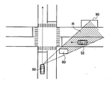
図12に示すように、自車両50は、1車線道路を走行しており、次の交差点を直進する予定である。また、他車両52は、1車線道路を走行している。図12に示すRは、建物80により形成される、自車両50の死角領域を示す。他車両52及び建物80は、自車両50の側方(前側方)に位置し、物体検出装置1によって検出される。 As shown in FIG. 12, the own vehicle 50 is traveling on a one-lane road and is scheduled to go straight on at the next intersection. Further, the other vehicle 52 is traveling on a one-lane road. R shown in FIG. 12 indicates a blind spot region of the own vehicle 50 formed by the building 80. The other vehicle 52 and the building 80 are located on the side (front side) of the own vehicle 50 and are detected by the object detection device 1.

図12に示す走行シーンにおいて、他車両52は死角領域Rに進入していないため、物体検出装置1は他車両52を検出できる。他車両52の前方右側には、進入可能な駐車場90がある。他車両52の矢印に示すように、他車両52の進路として2つの進路が考えられる。一つの進路は、他車両52がそのまま直進する進路である。もう一つの進路は、他車両52が右折して駐車場90に進入する進路である。 In the traveling scene shown in FIG. 12, since the other vehicle 52 has not entered the blind spot region R, the object detection device 1 can detect the other vehicle 52. There is an accessible parking lot 90 on the front right side of the other vehicle 52. As shown by the arrow of the other vehicle 52, two paths can be considered as the course of the other vehicle 52. One course is a course in which the other vehicle 52 goes straight as it is. The other course is a course in which another vehicle 52 turns right and enters the parking lot 90.

図13に示す走行シーンは、図12に示す走行シーンから検出可能時間T1が経過した後の走行シーンである。図13に示すように、検出可能時間T1が経過した後に、他車両52が検出されなくなった場合、進路予測部17は、他車両52は直進したと予測する。 The traveling scene shown in FIG. 13 is a traveling scene after the detectable time T1 has elapsed from the traveling scene shown in FIG. As shown in FIG. 13, when the other vehicle 52 is no longer detected after the detectable time T1 has elapsed, the course prediction unit 17 predicts that the other vehicle 52 has traveled straight.

図14に示す走行シーンは、図12に示す走行シーンから検出可能時間T1が経過する前の走行シーンである。検出可能時間T1が経過する前に、他車両52が死角領域Rに進入したということは、他車両52が右折した可能性が高いことを意味する。したがって、検出可能時間T1が経過する前に、他車両52が死角領域Rに進入した場合、進路予測部17は、他車両52は右折したと予測する。 The traveling scene shown in FIG. 14 is a traveling scene before the detectable time T1 elapses from the traveling scene shown in FIG. The fact that the other vehicle 52 has entered the blind spot region R before the detectable time T1 has elapsed means that it is highly possible that the other vehicle 52 has turned right. Therefore, if the other vehicle 52 enters the blind spot region R before the detectable time T1 elapses, the course prediction unit 17 predicts that the other vehicle 52 has turned right.

次に、図15A及び図15Bのフローチャートを参照して、車両挙動予測装置の一動作例を説明する。 Next, an operation example of the vehicle behavior prediction device will be described with reference to the flowcharts of FIGS. 15A and 15B.

ステップS101において、物体検出装置1は、複数の物体検出センサを用いて、自車両50の前方の物体(他車両51)を検出する。また、物体検出装置1は、自車両50から見て他車両51より遠方を走行する移動物体(他車両52)を検出する。処理はステップS103に進み、検出統合部4は、複数の物体検出センサの各々から得られた複数の検出結果を統合して、各他車両に対して一つの検出結果を出力する。そして、物体追跡部5が、検出及び統合された各他車両を追跡する。 In step S101, the object detection device 1 detects an object (another vehicle 51) in front of the own vehicle 50 by using a plurality of object detection sensors. Further, the object detection device 1 detects a moving object (other vehicle 52) traveling farther than the other vehicle 51 when viewed from the own vehicle 50. The process proceeds to step S103, and the detection integration unit 4 integrates a plurality of detection results obtained from each of the plurality of object detection sensors and outputs one detection result to each other vehicle. Then, the object tracking unit 5 tracks each other vehicle that has been detected and integrated.

処理はステップS105に進み、自車位置推定装置2は、位置検出センサを用いて、自車両50の絶対位置を計測する。処理はステップS107に進み、地図取得装置3は、自車両50が走行する道路の構造を示す地図情報を取得する。処理はステップS109に進み、地図内位置演算部6は、ステップS105で計測された自車両50の絶対位置、及びステップS107で取得された地図データから、地図上における自車両50の位置を推定する。 The process proceeds to step S105, and the own vehicle position estimation device 2 measures the absolute position of the own vehicle 50 by using the position detection sensor. The process proceeds to step S107, and the map acquisition device 3 acquires map information indicating the structure of the road on which the own vehicle 50 travels. The process proceeds to step S109, and the position calculation unit 6 in the map estimates the position of the own vehicle 50 on the map from the absolute position of the own vehicle 50 measured in step S105 and the map data acquired in step S107. ..

処理はステップS111に進み、意図予測部12は、他車両51及び他車両52の挙動(進路)を予測する。図2に示す例では、意図予測部12は、他車両51の位置、向き、姿勢、ターンシグナルの点灯の有無などに基づいて、他車両51が次の交差点を右折する予定であると予測する。 The process proceeds to step S111, and the intention prediction unit 12 predicts the behavior (course) of the other vehicle 51 and the other vehicle 52. In the example shown in FIG. 2, the intention prediction unit 12 predicts that the other vehicle 51 will make a right turn at the next intersection based on the position, orientation, posture, whether or not the turn signal is lit, and the like. ..

処理はステップS113に進み、死角領域算出部13は、物体検出装置1によって検出された他車両51の位置に基づいて、他車両51によって形成される、自車両50の死角領域Rを算出する。処理はステップS115に進み、進入タイミング推測部14は、他車両52が検出された後に他車両52が直進した場合の、他車両52が検出された時から他車両52が死角領域Rに進入するまでの時間である検出可能時間T1を推測する。 The process proceeds to step S113, and the blind spot area calculation unit 13 calculates the blind spot area R of the own vehicle 50 formed by the other vehicle 51 based on the position of the other vehicle 51 detected by the object detection device 1. The process proceeds to step S115, and the approach timing estimation unit 14 enters the blind spot region R from the time when the other vehicle 52 is detected when the other vehicle 52 goes straight after the other vehicle 52 is detected. The detectable time T1 which is the time until is estimated.

処理はステップS119に進み、進入判定部15は、検出可能時間T1が経過する前に、他車両52が死角領域Rに進入したか否かを判定する。検出可能時間T1が経過する前に、他車両52が死角領域Rに進入した場合(ステップS119でYes)、処理はステップS121、ステップS125に進む。 The process proceeds to step S119, and the approach determination unit 15 determines whether or not the other vehicle 52 has entered the blind spot region R before the detectable time T1 elapses. If the other vehicle 52 enters the blind spot region R before the detectable time T1 elapses (Yes in step S119), the process proceeds to step S121 and step S125.

ステップS121において、物体検出装置1は、他車両52が死角領域Rに進入する直前における他車両52と自車両50との距離を取得する。処理はステップS123に進み、進路予測部17は、ステップS121で取得された距離に基づいて他車両52の挙動が変化した可能性を変更する。本実施形態において、移動物体の挙動の変化とは、移動物体の車線変更、左折、右折のいずれかを意味する。例えば、図4に示す例において、他車両52と自車両50との距離(図示しない)が短いほど、進路予測部17は、他車両52が車線変更した可能性を増加させる。センサの誤差は、自車両50からの距離が短いほど小さいからである。 In step S121, the object detection device 1 acquires the distance between the other vehicle 52 and the own vehicle 50 immediately before the other vehicle 52 enters the blind spot region R. The process proceeds to step S123, and the course prediction unit 17 changes the possibility that the behavior of the other vehicle 52 has changed based on the distance acquired in step S121. In the present embodiment, the change in the behavior of the moving object means any one of lane change, left turn, and right turn of the moving object. For example, in the example shown in FIG. 4, the shorter the distance (not shown) between the other vehicle 52 and the own vehicle 50, the more likely that the course prediction unit 17 has changed lanes. This is because the error of the sensor is smaller as the distance from the own vehicle 50 is shorter.

ステップS125において、軌道取得部16は、他車両52が検出された時から他車両52が死角領域Rに進入する直前までの、他車両52の軌道(他車両52の車線上の位置)を取得する。処理はステップS127に進み、進路予測部17は、ステップS125で取得された軌道に基づいて他車両52の挙動が変化した可能性を増加させる。例えば、図4に示す例において、他車両52が検出された時から他車両52が死角領域Rに進入する直前までの、他車両52の軌道が直進を示す軌道と異なる場合、進路予測部17は、他車両52が車線変更した可能性を増加させる。また、図11に示す例において、他車両52が検出された時から他車両52が側道70に進入するまでの、他車両52の軌道が直進を示す軌道と異なる場合、進路予測部17は、他車両52は左折した可能性を増加させる。なお、進路予測部17は、ステップS121、123、125、127に係る処理を行うことなく、他車両52の進路を予測してもよい。換言すれば、検出可能時間T1が経過する前に、他車両52が死角領域Rに進入したことのみに基づいて、進路予測部17は他車両52が車線変更した、左折した、あるいは右折したと予測してもよい。なお、図11に示す例において、他車両52が検出された時から他車両52が死角領域Rに進入する直前までの、他車両52の軌道が走行車線の左側(路肩側)を走行する軌道を示す場合、進路予測部17は、他車両52が左折した可能性を増加させ、他車両52は左折したと予測してもよい。 In step S125, the track acquisition unit 16 acquires the track (position on the lane of the other vehicle 52) of the other vehicle 52 from the time when the other vehicle 52 is detected to just before the other vehicle 52 enters the blind spot region R. do. The process proceeds to step S127, and the course prediction unit 17 increases the possibility that the behavior of the other vehicle 52 has changed based on the track acquired in step S125. For example, in the example shown in FIG. 4, when the track of the other vehicle 52 is different from the track indicating straight travel from the time when the other vehicle 52 is detected until immediately before the other vehicle 52 enters the blind spot region R, the course prediction unit 17 Increases the possibility that the other vehicle 52 has changed lanes. Further, in the example shown in FIG. 11, when the track of the other vehicle 52 is different from the track indicating straight travel from the time when the other vehicle 52 is detected until the other vehicle 52 enters the frontage road 70, the course prediction unit 17 , The other vehicle 52 increases the possibility of turning left. The course prediction unit 17 may predict the course of another vehicle 52 without performing the process according to steps S121, 123, 125, 127. In other words, the course prediction unit 17 indicates that the other vehicle 52 has changed lanes, turned left, or turned right based only on the fact that the other vehicle 52 has entered the blind spot region R before the detectable time T1 has elapsed. You may predict. In the example shown in FIG. 11, the track of the other vehicle 52 travels on the left side (shoulder side) of the traveling lane from the time when the other vehicle 52 is detected until immediately before the other vehicle 52 enters the blind spot region R. In the case of, the course prediction unit 17 may increase the possibility that the other vehicle 52 has turned left, and may predict that the other vehicle 52 has turned left.

一方、検出可能時間T1が経過した後に、他車両52が死角領域Rに進入した場合(ステップS119でNo)、処理はステップS129に進む。ステップS129において、進路予測部17は、他車両52が検出された時から他車両52が死角領域Rに進入する直前までの、他車両52の軌道を取得する。他車両52の軌道が直進を示す場合、進路予測部17は、他車両52が直進した可能性を増加させ、他車両52は直進したと予測する(ステップS137)。一方、他車両52の軌道が取得されない場合(ステップS129でNo)、処理はステップS131に進み、進路予測部17は、他車両52が死角領域Rに進入する直前の他車両52の速度変化を取得する。処理はステップS133に進み、進路予測部17は、ステップS131で取得された速度変化に基づいて他車両52が直進した可能性を増加させる。なお、進路予測部17は、ステップS129、131、133に係る処理を行うことなく、他車両52の進路を予測してもよい。換言すれば、検出可能時間T1が経過した後に、他車両52が死角領域Rに進入したことのみに基づいて、進路予測部17は他車両52が直進したと予測してもよい。 On the other hand, when the other vehicle 52 enters the blind spot region R after the detectable time T1 has elapsed (No in step S119), the process proceeds to step S129. In step S129, the course prediction unit 17 acquires the track of the other vehicle 52 from the time when the other vehicle 52 is detected to just before the other vehicle 52 enters the blind spot region R. When the track of the other vehicle 52 indicates straight travel, the course prediction unit 17 increases the possibility that the other vehicle 52 has traveled straight, and predicts that the other vehicle 52 has traveled straight (step S137). On the other hand, when the track of the other vehicle 52 is not acquired (No in step S129), the process proceeds to step S131, and the course prediction unit 17 changes the speed of the other vehicle 52 immediately before the other vehicle 52 enters the blind spot region R. get. The process proceeds to step S133, and the course prediction unit 17 increases the possibility that the other vehicle 52 goes straight based on the speed change acquired in step S131. The course prediction unit 17 may predict the course of another vehicle 52 without performing the process according to steps S129, 131, 133. In other words, the course prediction unit 17 may predict that the other vehicle 52 has traveled straight based only on the fact that the other vehicle 52 has entered the blind spot region R after the detectable time T1 has elapsed.

なお、車両挙動予測装置は、予測した他車両52の進路に基づいて自車両を制御してもよい。この点について図16を参照して説明する。 The vehicle behavior prediction device may control the own vehicle based on the predicted course of the other vehicle 52. This point will be described with reference to FIG.

ステップS201において、車両制御部30は、進路予測部17によって予測された他車両52の進路を取得する。処理は、ステップS203に進み、車両制御部30は、予め設定された自車両50の進路を取得する。 In step S201, the vehicle control unit 30 acquires the course of the other vehicle 52 predicted by the course prediction unit 17. The process proceeds to step S203, and the vehicle control unit 30 acquires a preset course of the own vehicle 50.

処理はステップS205に進み、車両制御部30は、他車両52の進路が自車両50の進路と交差するか否かを判定する。他車両52の進路が自車両50の進路と交差する場合(ステップS205でYes)、処理はステップS207に進み、車両制御部30は、他車両52が走行する道路が優先道路か否かを判定する。優先道路の判断は、道路構造、道路標識、交通規則などに基づいて行われる。他車両52が走行する道路が優先道路である場合(ステップS207でYes)、処理はステップS209に進み、車両制御部30は、自車両50を減速または停止させるための速度プロファイルを算出する。速度プロファイルとは、自車両50の速度を時間の関数として示すものである。図4に示す例では、他車両52の進路が自車両50の進路と交差し、かつ他車両52が走行する道路が優先道路である。この場合、車両制御部30は他車両52の通過を待つために、自車両50を減速または停止させるための速度プロファイルを算出する。処理はステップS217に進み、車両制御部30は速度プロファイルに基づいてブレーキアクチュエータなどを制御して自動運転制御を実行する。これにより、急減速は抑制される。 The process proceeds to step S205, and the vehicle control unit 30 determines whether or not the course of the other vehicle 52 intersects the course of the own vehicle 50. When the course of the other vehicle 52 intersects the course of the own vehicle 50 (Yes in step S205), the process proceeds to step S207, and the vehicle control unit 30 determines whether the road on which the other vehicle 52 travels is a priority road. do. Priority roads are determined based on road structure, road signs, traffic rules, etc. When the road on which the other vehicle 52 travels is a priority road (Yes in step S207), the process proceeds to step S209, and the vehicle control unit 30 calculates a speed profile for decelerating or stopping the own vehicle 50. The speed profile shows the speed of the own vehicle 50 as a function of time. In the example shown in FIG. 4, the road where the course of the other vehicle 52 intersects the course of the own vehicle 50 and the other vehicle 52 travels is the priority road. In this case, the vehicle control unit 30 calculates a speed profile for decelerating or stopping the own vehicle 50 in order to wait for the passage of the other vehicle 52. The process proceeds to step S217, and the vehicle control unit 30 controls the brake actuator and the like based on the speed profile to execute automatic driving control. As a result, sudden deceleration is suppressed.

他車両52の進路が自車両50の進路と交差しない場合(ステップS205でNo)、処理はステップS211に進み、車両制御部30は、他車両52の進路の可能性の高さに応じて速度プロファイルを算出する。図3に示すように、他車両52は直進した可能性が高い場合、車両制御部30は一定の速度を示す速度プロファイルを算出する。処理はステップS217に進み、車両制御部30は速度プロファイルに基づいて自動運転制御を実行する。これにより、スムーズな自動運転が実現する。 If the course of the other vehicle 52 does not intersect the course of the own vehicle 50 (No in step S205), the process proceeds to step S211 and the vehicle control unit 30 speeds according to the high possibility of the course of the other vehicle 52. Calculate the profile. As shown in FIG. 3, when the other vehicle 52 is likely to go straight, the vehicle control unit 30 calculates a speed profile indicating a constant speed. The process proceeds to step S217, and the vehicle control unit 30 executes automatic driving control based on the speed profile. As a result, smooth automatic operation is realized.

他車両52が走行する道路が優先道路でない場合(ステップS207でNo)、つまり自車両50が走行する道路が優先道路である場合、処理はステップS215に進む。ステップS215において、車両制御部30は一定の速度を示す速度プロファイルを算出する。処理はステップS217に進み、車両制御部30は速度プロファイルに基づいて自動運転制御を実行する。これにより、スムーズな自動運転が実現する。 If the road on which the other vehicle 52 travels is not a priority road (No in step S207), that is, if the road on which the own vehicle 50 travels is a priority road, the process proceeds to step S215. In step S215, the vehicle control unit 30 calculates a speed profile indicating a constant speed. The process proceeds to step S217, and the vehicle control unit 30 executes automatic driving control based on the speed profile. As a result, smooth automatic operation is realized.

以上説明したように、本実施形態に係る車両挙動予測装置によれば、以下の作用効果が得られる。 As described above, according to the vehicle behavior prediction device according to the present embodiment, the following effects can be obtained.

物体検出装置1は、自車両50の前方または側方の物体(他車両51または建物80)を検出する。また、物体検出装置1は、自車両50の前方または側方の物体の自車両50に対する位置を検出する。また、物体検出装置1は、自車両50から見て物体より遠方を走行する移動物体(他車両52)を検出する。死角領域算出部13は、物体検出装置1によって検出された物体の位置に基づいて、物体により形成される、自車両50の死角領域Rを算出する。進入タイミング推測部14は、移動物体を検出した後に移動物体が直進した場合の、移動物体を検出した時から移動物体が死角領域Rに進入するまでの時間である検出可能時間T1を推測する。進入判定部15は、検出可能時間T1が経過する前に、移動物体が死角領域Rに進入したか否かを判定する。車両制御部30は、判定した結果に基づいて、移動物体の進路を予測する。図4に示す例では、検出可能時間T1が経過する前に、他車両52(移動物体)が死角領域Rに進入した場合、進路予測部17は、他車両52は車線変更したと予測する。したがって、本実施形態に係る車両挙動予測装置は、移動物体の進路を早期に予測することができる。なお、上述したように、自車両50の前方または側方の物体は、移動物体(他車両51)でもよく、静止物体(建物80)でもよい。また、他車両51は、自車両50と同じ道路を自車両50が走行する方向と逆の方向に走行する対向車両である。また、静止物体は建物80に限定されない。静止物体は駐車車両を含む。また、検出可能時間T1は、他車両52が検出された後に他車両52が所定の進路で進行した場合の、他車両52が検出された時から他車両52が死角領域Rに進入するまでの時間であってもよい。所定の進路とは、直進と車線変更を含む。物体検出装置1は、推測した検出可能時間T1と、他車両52が検出された時から他車両52が実際に死角領域Rに進入するまでの時間である実際の検出可能時間とを比較し、比較した結果に基づいて、他車両52の進路を予測してもよい。 The object detection device 1 detects an object (another vehicle 51 or a building 80) in front of or to the side of the own vehicle 50. Further, the object detection device 1 detects the position of the object in front of or to the side of the own vehicle 50 with respect to the own vehicle 50. Further, the object detection device 1 detects a moving object (another vehicle 52) traveling farther than the object when viewed from the own vehicle 50. The blind spot area calculation unit 13 calculates the blind spot area R of the own vehicle 50 formed by the object based on the position of the object detected by the object detection device 1. The approach timing estimation unit 14 estimates the detectable time T1 which is the time from the time when the moving object is detected until the moving object enters the blind spot region R when the moving object goes straight after detecting the moving object. The approach determination unit 15 determines whether or not the moving object has entered the blind spot region R before the detectable time T1 elapses. The vehicle control unit 30 predicts the course of the moving object based on the determination result. In the example shown in FIG. 4, if the other vehicle 52 (moving object) enters the blind spot region R before the detectable time T1 elapses, the course prediction unit 17 predicts that the other vehicle 52 has changed lanes. Therefore, the vehicle behavior prediction device according to the present embodiment can predict the course of a moving object at an early stage. As described above, the object in front of or to the side of the own vehicle 50 may be a moving object (another vehicle 51) or a stationary object (building 80). Further, the other vehicle 51 is an oncoming vehicle that travels on the same road as the own vehicle 50 in the direction opposite to the direction in which the own vehicle 50 travels. Further, the stationary object is not limited to the building 80. Stationary objects include parked vehicles. Further, the detectable time T1 is the time when the other vehicle 52 travels in a predetermined course after the other vehicle 52 is detected, from the time when the other vehicle 52 is detected until the other vehicle 52 enters the blind spot region R. It may be time. The predetermined course includes going straight and changing lanes. The object detection device 1 compares the estimated detectable time T1 with the actual detectable time, which is the time from the time when the other vehicle 52 is detected until the other vehicle 52 actually enters the blind spot region R. The course of the other vehicle 52 may be predicted based on the result of the comparison.

移動物体が走行する道路が複数の車線で構成され、自車両50が移動物体を検出した際に移動物体が複数の車線のうち、自車両50から見て最も遠い車線以外を走行している場合において、進入判定部15が、検出可能時間T1が経過する前に、移動物体が死角領域Rに進入したと判定した場合、進路予測部17は移動物体が車線変更したと予測する。図2に示す例では、他車両52(移動物体)が走行する道路が複数の車線(2車線)で構成され、自車両50が他車両52を検出した際に他車両52が複数の車線のうち、自車両50から見て最も遠い車線以外を走行している。図2において、他車両52が走行する車線のうち、自車両50から見て最も遠い車線とは左側車線である。図2において、他車両52は右側車線を走行している。そして、図4に示すように、検出可能時間T1が経過する前に、他車両52が死角領域Rに進入した場合、進路予測部17は、他車両52は車線変更したと予測する。したがって、本実施形態に係る車両挙動予測装置は、移動物体の進路を早期に予測することができる。 When the road on which the moving object travels is composed of a plurality of lanes, and the moving object is traveling in a lane other than the farthest lane from the own vehicle 50 among the plurality of lanes when the own vehicle 50 detects the moving object. When the approach determination unit 15 determines that the moving object has entered the blind spot region R before the detectable time T1 has elapsed, the course prediction unit 17 predicts that the moving object has changed lanes. In the example shown in FIG. 2, the road on which the other vehicle 52 (moving object) travels is composed of a plurality of lanes (two lanes), and when the own vehicle 50 detects the other vehicle 52, the other vehicle 52 has a plurality of lanes. Of these, the vehicle is traveling in a lane other than the farthest lane when viewed from the own vehicle 50. In FIG. 2, among the lanes in which the other vehicle 52 travels, the lane farthest from the own vehicle 50 is the left lane. In FIG. 2, the other vehicle 52 is traveling in the right lane. Then, as shown in FIG. 4, if the other vehicle 52 enters the blind spot region R before the detectable time T1 elapses, the course prediction unit 17 predicts that the other vehicle 52 has changed lanes. Therefore, the vehicle behavior prediction device according to the present embodiment can predict the course of a moving object at an early stage.

移動物体が走行する道路の左側に進入可能な場所が存在する場合において、進入判定部15が、検出可能時間T1が経過する前に、移動物体が死角領域Rに進入したと判定した場合、進路予測部17は移動物体が左折したと予測する。図9に示す例では、他車両52(移動物体)が走行する道路の左側に進入可能な場所(側道70)が存在する。そして、図11に示すように、検出可能時間T1が経過する前に、他車両52が死角領域Rに進入した場合、進路予測部17は、他車両52は左折したと予測する。したがって、本実施形態に係る車両挙動予測装置は、移動物体の進路を早期に予測することができる。 If there is an accessible place on the left side of the road on which the moving object travels, and the approach determination unit 15 determines that the moving object has entered the blind spot region R before the detectable time T1 elapses, the course The prediction unit 17 predicts that the moving object has turned left. In the example shown in FIG. 9, there is an accessible place (frontage road 70) on the left side of the road on which the other vehicle 52 (moving object) travels. Then, as shown in FIG. 11, if the other vehicle 52 enters the blind spot region R before the detectable time T1 elapses, the course prediction unit 17 predicts that the other vehicle 52 has turned left. Therefore, the vehicle behavior prediction device according to the present embodiment can predict the course of a moving object at an early stage.

移動物体が走行する道路の右側に進入可能な場所が存在する場合において、進入判定部15が、検出可能時間T1が経過する前に、移動物体が死角領域Rに進入したと判定した場合、進路予測部17は移動物体が右折したと予測する。図12に示す例では、他車両52(移動物体)が走行する道路の右側に進入可能な場所(駐車場90)が存在する。そして、図14に示すように、検出可能時間T1が経過する前に、他車両52が死角領域Rに進入した場合、進路予測部17は、他車両52は右折したと予測する。したがって、本実施形態に係る車両挙動予測装置は、移動物体の進路を早期に予測することができる。 If there is an accessible place on the right side of the road on which the moving object travels, and the approach determination unit 15 determines that the moving object has entered the blind spot region R before the detectable time T1 elapses, the course The prediction unit 17 predicts that the moving object has turned right. In the example shown in FIG. 12, there is a place (parking lot 90) that can be entered on the right side of the road on which the other vehicle 52 (moving object) travels. Then, as shown in FIG. 14, if the other vehicle 52 enters the blind spot region R before the detectable time T1 elapses, the course prediction unit 17 predicts that the other vehicle 52 has turned right. Therefore, the vehicle behavior prediction device according to the present embodiment can predict the course of a moving object at an early stage.

進入判定部15が、検出可能時間T1が経過する前に、移動物体が死角領域Rに進入したと判定した場合、進路予測部17は移動物体と自車両50との距離が短いほど、移動物体の挙動が変化した可能性を増加させる。本実施形態において、移動物体の挙動の変化とは、移動物体の車線変更、左折、右折のいずれかを意味する。つまり、進路予測部17は移動物体と自車両50との距離が短いほど、移動物体は車線変更した可能性、または左折した可能性、または右折した可能性を増加させる。センサの誤差は、自車両50からの距離が短いほど小さいため、上述したように、進路予測部17は可能性を増加させることにより、精度よく移動物体の進路を予測することができる。 When the approach determination unit 15 determines that the moving object has entered the blind spot region R before the detectable time T1 elapses, the course prediction unit 17 increases the shorter the distance between the moving object and the own vehicle 50, the more the moving object. Increases the likelihood that the behavior of the object has changed. In the present embodiment, the change in the behavior of the moving object means any one of lane change, left turn, and right turn of the moving object. That is, the shorter the distance between the moving object and the own vehicle 50, the more the path predicting unit 17 increases the possibility that the moving object has changed lanes, turned left, or turned right. Since the error of the sensor is smaller as the distance from the own vehicle 50 is shorter, as described above, the course prediction unit 17 can accurately predict the course of the moving object by increasing the possibility.

進入判定部15が、検出可能時間T1が経過する前に、移動物体が死角領域Rに進入したと判定した場合、進路予測部17は移動物体が検出された時から移動物体が死角領域Rに進入する直前までの、移動物体の軌道に基づいて移動物体の挙動が変化した可能性を増加させる。図4に示す例において、他車両52(移動物体)が検出された時から他車両52が死角領域Rに進入する直前までの、他車両52の軌道が直進を示す軌道と異なる場合、進路予測部17は、他車両52が車線変更した可能性を増加させる。このように、進路予測部17は移動物体の軌道に基づいて移動物体の挙動が変化した可能性を増加させることにより、精度よく移動物体の進路を予測することができる。 If the approach determination unit 15 determines that the moving object has entered the blind spot area R before the detectable time T1 has elapsed, the course prediction unit 17 will move the moving object into the blind spot area R from the time when the moving object is detected. Increases the likelihood that the behavior of the moving object has changed based on the trajectory of the moving object until just before entering. In the example shown in FIG. 4, when the track of the other vehicle 52 is different from the track indicating straight travel from the time when the other vehicle 52 (moving object) is detected to just before the other vehicle 52 enters the blind spot region R, the course prediction The unit 17 increases the possibility that the other vehicle 52 has changed lanes. In this way, the course prediction unit 17 can accurately predict the course of the moving object by increasing the possibility that the behavior of the moving object has changed based on the trajectory of the moving object.

進入判定部15が、検出可能時間T1が経過した後に、移動物体が死角領域Rに進入したと判定した場合、進路予測部17は移動物体が直進したと予測する。これにより、図3に示すように、自車両50は他車両52(移動物体)を待つことなく交差点を通過できる。すなわち、自車両50のスムーズな走行に寄与する。 When the approach determination unit 15 determines that the moving object has entered the blind spot region R after the detectable time T1 has elapsed, the course prediction unit 17 predicts that the moving object has traveled straight. As a result, as shown in FIG. 3, the own vehicle 50 can pass through the intersection without waiting for another vehicle 52 (moving object). That is, it contributes to the smooth running of the own vehicle 50.

進入判定部15が、検出可能時間T1が経過した後に、移動物体が死角領域Rに進入したと判定した場合、進路予測部17は移動物体と自車両50との距離が短いほど、移動物体が直進した可能性を増加させてもよい。また、移動物体が検出された時から移動物体が死角領域Rに進入する直前までの、移動物体の軌道が直進を示す場合、進路予測部17は他車両52が直進した可能性を増加させてもよい。進路予測部17は可能性を増加させることにより、精度よく移動物体の進路を予測することができる。 When the approach determination unit 15 determines that the moving object has entered the blind spot region R after the detectable time T1 has elapsed, the course prediction unit 17 determines that the shorter the distance between the moving object and the own vehicle 50, the more the moving object becomes. You may increase the possibility of going straight. Further, when the trajectory of the moving object indicates straight travel from the time when the moving object is detected to just before the moving object enters the blind spot region R, the course prediction unit 17 increases the possibility that the other vehicle 52 has traveled straight. May be good. By increasing the possibility, the course prediction unit 17 can accurately predict the course of a moving object.

車両制御部30は、進路予測部17によって予測された他車両52の進路に基づいて、自車両50の速度プロファイルを算出する。そして、車両制御部30は、算出した速度プロファイルに基づいて自車両50を制御する。これにより、急減速の抑制、またはスムーズな自動運転が実現しうる。例えば、図4に示すように、他車両52の進路が自車両50の進路と交差し、かつ他車両52が走行する道路が優先道路である場合、車両制御部30は他車両52の通過を待つために、自車両50を減速または停止させるための速度プロファイルを算出する。車両制御部30は速度プロファイルに基づいてブレーキアクチュエータなどを制御して自動運転制御を実行する。これにより、急減速は抑制される。 The vehicle control unit 30 calculates the speed profile of the own vehicle 50 based on the course of the other vehicle 52 predicted by the course prediction unit 17. Then, the vehicle control unit 30 controls the own vehicle 50 based on the calculated speed profile. As a result, sudden deceleration can be suppressed or smooth automatic operation can be realized. For example, as shown in FIG. 4, when the course of the other vehicle 52 intersects the course of the own vehicle 50 and the road on which the other vehicle 52 travels is a priority road, the vehicle control unit 30 passes through the other vehicle 52. To wait, calculate a speed profile for decelerating or stopping the own vehicle 50. The vehicle control unit 30 controls a brake actuator or the like based on the speed profile to execute automatic driving control. As a result, sudden deceleration is suppressed.

また、移動物体の進路が自車両50の進路と交差し、かつ、自車両50が走行する道路が優先道路である場合、車両制御部30は、一定の速度を示す速度プロファイルを算出し、この速度プロファイルに基づいて自車両50を制御してもよい。また、移動物体の進路が自車両50の進路と交差しない場合、車両制御部30は、一定の速度を示す速度プロファイルを算出し、この速度プロファイルに基づいて自車両50を制御してもよい。これにより、スムーズな自動運転が実現する。 Further, when the course of the moving object intersects the course of the own vehicle 50 and the road on which the own vehicle 50 travels is a priority road, the vehicle control unit 30 calculates a speed profile indicating a constant speed, and this The own vehicle 50 may be controlled based on the speed profile. Further, when the course of the moving object does not intersect the course of the own vehicle 50, the vehicle control unit 30 may calculate a speed profile indicating a constant speed and control the own vehicle 50 based on this speed profile. As a result, smooth automatic operation is realized.

上述の実施形態に記載される各機能は、1または複数の処理回路により実装され得る。処理回路は、電気回路を含む処理装置等のプログラムされた処理装置を含む。処理回路は、また、記載された機能を実行するようにアレンジされた特定用途向け集積回路(ASIC)や回路部品等の装置を含む。また、車両挙動予測装置は、コンピュータの機能を改善しうる。 Each of the functions described in the above embodiments may be implemented by one or more processing circuits. The processing circuit includes a programmed processing device such as a processing device including an electric circuit. Processing circuits also include devices such as application specific integrated circuits (ASICs) and circuit components arranged to perform the described functions. In addition, the vehicle behavior predictor can improve the function of the computer.

上記のように、本発明の実施形態を記載したが、この開示の一部をなす論述及び図面はこの発明を限定するものであると理解すべきではない。この開示から当業者には様々な代替実施の形態、実施例及び運用技術が明らかとなろう。 As mentioned above, embodiments of the invention have been described, but the statements and drawings that form part of this disclosure should not be understood to limit the invention. This disclosure will reveal to those skilled in the art various alternative embodiments, examples and operational techniques.

1 物体検出装置
2 自車位置推定装置
3 地図取得装置
4 検出統合部
5 物体追跡部
6 地図内位置演算部
10 挙動予測部
11 車線判定部
12 意図予測部
13 死角領域算出部
14 進入タイミング推測部
15 進入判定部
16 軌道取得部
17 進路予測部
30 車両制御部
1 Object detection device 2 Own vehicle position estimation device 3 Map acquisition device 4 Detection integration unit 5 Object tracking unit 6 In-map position calculation unit 10 Behavior prediction unit 11 Lane determination unit 12 Intention prediction unit 13 Blind spot area calculation unit 14 Entry timing estimation unit 15 Approach determination unit 16 Track acquisition unit 17 Course prediction unit 30 Vehicle control unit

Claims (17)

自車両に搭載されたセンサを用いて前記自車両の前方または側方の物体の前記自車両に対する位置を検出し、
前記センサを用いて前記自車両から見て前記物体より遠方を走行する移動物体を検出し、
前記位置に基づいて、前記物体により形成される、前記センサが検出することができない前記自車両の死角領域を算出し、
前記移動物体を検出した後に前記移動物体が所定の進路で進行した場合の、前記移動物体を検出した時から前記移動物体が前記死角領域に進入するまでの時間である検出可能時間を推測し、
推測した前記検出可能時間と、前記移動物体を検出した時から前記移動物体が実際に前記死角領域に進入するまでの時間である実際の検出可能時間とを比較し、
比較した結果に基づいて、前記移動物体の進路を予測する
ことを特徴とする車両挙動予測方法。
A sensor mounted on the own vehicle is used to detect the position of an object in front of or to the side of the own vehicle with respect to the own vehicle.
Using the sensor, a moving object traveling farther than the object as seen from the own vehicle is detected.
Based on the position, the blind spot region of the own vehicle, which is formed by the object and cannot be detected by the sensor, is calculated.
When the moving object travels in a predetermined course after detecting the moving object, the detectable time, which is the time from the time when the moving object is detected until the moving object enters the blind spot region, is estimated.
The estimated detectable time is compared with the actual detectable time, which is the time from the time when the moving object is detected until the moving object actually enters the blind spot region.
A vehicle behavior prediction method, characterized in that the course of a moving object is predicted based on the results of comparison.
前記所定の進路は直進であり、
推測した前記検出可能時間よりも前記実際の検出可能時間が短いか否かを比較した結果に基づいて、前記移動物体の進路を予測する
ことを特徴とする請求項1に記載の車両挙動予測方法。
The predetermined course is straight ahead,
The vehicle behavior prediction method according to claim 1, wherein the course of the moving object is predicted based on the result of comparing whether or not the actual detectable time is shorter than the estimated detectable time. ..
前記物体は、前記自車両と同じ道路を前記自車両が走行する方向と逆の方向に走行する対向車両である
ことを特徴とする請求項1または2に記載の車両挙動予測方法。
The vehicle behavior prediction method according to claim 1 or 2, wherein the object is an oncoming vehicle traveling on the same road as the own vehicle in a direction opposite to the direction in which the own vehicle travels.
前記物体は、静止物体である
ことを特徴とする請求項1または2に記載の車両挙動予測方法。
The vehicle behavior prediction method according to claim 1 or 2, wherein the object is a stationary object.
前記所定の進路は直進であり、前記移動物体が走行する道路が複数の車線で構成され、前記自車両が前記移動物体を検出した際に前記移動物体が前記複数の車線のうち、前記自車両から見て最も遠い車線以外を走行している場合において、
推測した前記検出可能時間よりも前記実際の検出可能時間が短い場合、前記移動物体は車線変更したと予測する
ことを特徴とする請求項1~4のいずれか1項に記載の車両挙動予測方法。
The predetermined course is straight, the road on which the moving object travels is composed of a plurality of lanes, and when the own vehicle detects the moving object, the moving object is the own vehicle among the plurality of lanes. When driving in a lane other than the farthest lane when viewed from
The vehicle behavior prediction method according to any one of claims 1 to 4, wherein when the actual detectable time is shorter than the estimated detectable time, the moving object is predicted to have changed lanes. ..
前記所定の進路は直進であり、前記移動物体が走行する道路の左側に進入可能な場所が存在する場合において、
推測した前記検出可能時間よりも前記実際の検出可能時間が短い場合、前記移動物体は左折したと予測する
ことを特徴とする請求項1~5のいずれか1項に記載の車両挙動予測方法。
When the predetermined course is straight ahead and there is an accessible place on the left side of the road on which the moving object travels,
The vehicle behavior prediction method according to any one of claims 1 to 5, wherein when the actual detectable time is shorter than the estimated detectable time, the moving object is predicted to have turned left.
前記所定の進路は直進であり、前記移動物体が走行する道路の右側に進入可能な場所が存在する場合において、
推測した前記検出可能時間よりも前記実際の検出可能時間が短い場合、前記移動物体は右折したと予測する
ことを特徴とする請求項1~6のいずれか1項に記載の車両挙動予測方法。
When the predetermined course is straight ahead and there is an accessible place on the right side of the road on which the moving object travels,
The vehicle behavior prediction method according to any one of claims 1 to 6, wherein when the actual detectable time is shorter than the estimated detectable time, the moving object is predicted to have turned right.
前記所定の進路は直進であり、推測した前記検出可能時間よりも前記実際の検出可能時間が短い場合、前記移動物体と前記自車両との距離が短いほど、前記移動物体の挙動が変化した可能性を増加させ、
前記可能性及び前記比較した結果に基づいて、前記移動物体の進路を予測する
ことを特徴とする請求項1~7のいずれか1項に記載の車両挙動予測方法。
When the predetermined course is straight and the actual detectable time is shorter than the estimated detectable time, the behavior of the moving object may change as the distance between the moving object and the own vehicle becomes shorter. Increase sex,
The vehicle behavior prediction method according to any one of claims 1 to 7, wherein the course of the moving object is predicted based on the possibility and the result of the comparison.
前記所定の進路は直進であり、推測した前記検出可能時間よりも前記実際の検出可能時間が短い場合、前記移動物体を検出した時から前記移動物体が前記死角領域に進入する直前までの、前記移動物体の軌道に基づいて前記移動物体の挙動が変化した可能性を増加させ、
前記可能性及び前記比較した結果に基づいて、前記移動物体の進路を予測する
ことを特徴とする請求項1~7のいずれか1項に記載の車両挙動予測方法。
When the predetermined path is straight and the actual detectable time is shorter than the estimated detectable time, the said Increasing the possibility that the behavior of the moving object has changed based on the trajectory of the moving object,
The vehicle behavior prediction method according to any one of claims 1 to 7, wherein the course of the moving object is predicted based on the possibility and the result of the comparison.
前記所定の進路は直進であり、前記実際の検出可能時間が推測した前記検出可能時間以上で場合、前記移動物体は直進したと予測する
ことを特徴とする請求項1~9のいずれか1項に記載の車両挙動予測方法。
One of claims 1 to 9, wherein the predetermined course is straight ahead, and when the actual detectable time is equal to or longer than the estimated detectable time, the moving object is predicted to go straight. The vehicle behavior prediction method described in.
前記移動物体と前記自車両との距離が短いほど、前記移動物体が直進した可能性を増加させ、または、前記移動物体を検出した時から前記移動物体が前記死角領域に進入する直前までの、前記移動物体の軌道に基づいて前記移動物体が直進した可能性を増加させ、
前記移動物体は直進したと予測する
ことを特徴とする請求項10に記載の車両挙動予測方法。
The shorter the distance between the moving object and the own vehicle, the greater the possibility that the moving object has traveled straight, or from the time when the moving object is detected until immediately before the moving object enters the blind spot region. Increasing the possibility that the moving object has traveled straight based on the trajectory of the moving object,
The vehicle behavior prediction method according to claim 10, wherein the moving object is predicted to travel straight.
前記移動物体の進路の予測結果に基づいて、前記自車両の速度を時間の関数として示す速度プロファイルを算出する
ことを特徴とする請求項1~11のいずれか1項に記載の車両挙動予測方法。
The vehicle behavior prediction method according to any one of claims 1 to 11, wherein a speed profile showing the speed of the own vehicle as a function of time is calculated based on the prediction result of the course of the moving object. ..
請求項12に記載された車両挙動予測方法を用いて前記自車両を制御する車両制御方法であって、
前記移動物体の進路が前記自車両の進路と交差し、かつ、前記移動物体が走行する道路が優先道路である場合、前記自車両を減速または停止させるための前記速度プロファイルを算出し、
前記速度プロファイルに基づいて前記自車両を制御する
ことを特徴とする車両制御方法。
A vehicle control method for controlling the own vehicle by using the vehicle behavior prediction method according to claim 12.
When the course of the moving object intersects the course of the own vehicle and the road on which the moving object travels is a priority road, the speed profile for decelerating or stopping the own vehicle is calculated.
A vehicle control method comprising controlling the own vehicle based on the speed profile.
請求項12に記載された車両挙動予測方法を用いて前記自車両を制御する車両制御方法であって、
前記移動物体の進路が前記自車両の進路と交差し、かつ、前記自車両が走行する道路が優先道路である場合、一定の速度を示す前記速度プロファイルを算出し、
前記速度プロファイルに基づいて前記自車両を制御する
ことを特徴とする車両制御方法。
A vehicle control method for controlling the own vehicle by using the vehicle behavior prediction method according to claim 12.
When the course of the moving object intersects the course of the own vehicle and the road on which the own vehicle travels is a priority road, the speed profile indicating a constant speed is calculated.
A vehicle control method comprising controlling the own vehicle based on the speed profile.
請求項12に記載された車両挙動予測方法を用いて前記自車両を制御する車両制御方法であって、
前記移動物体の進路が前記自車両の進路と交差しない場合、一定の速度を示す前記速度プロファイルを算出し、
前記速度プロファイルに基づいて前記自車両を制御する
ことを特徴とする車両制御方法。
A vehicle control method for controlling the own vehicle by using the vehicle behavior prediction method according to claim 12.
When the course of the moving object does not intersect the course of the own vehicle, the speed profile indicating a constant speed is calculated.
A vehicle control method comprising controlling the own vehicle based on the speed profile.
自車両の前方または側方の物体の前記自車両に対する位置、及び前記自車両から見て前記物体より遠方を走行する移動物体を検出するセンサと、
制御部とを備え、
前記制御部は、
前記センサによって検出された前記位置に基づいて、前記物体により形成される、前記センサが検出することができない前記自車両の死角領域を算出し、
前記センサによって前記移動物体が検出された後に前記移動物体が所定の進路で進行した場合の、前記移動物体を検出した時から前記移動物体が前記死角領域に進入するまでの時間である検出可能時間を推測し、
前記検出可能時間と、前記移動物体を検出した時から前記移動物体が実際に前記死角領域に進入するまでの時間である実際の検出可能時間とを比較し、
比較した結果に基づいて、前記移動物体の進路を予測する
ことを特徴とする車両挙動予測装置。
A sensor that detects the position of an object in front of or to the side of the own vehicle with respect to the own vehicle, and a moving object traveling farther than the object when viewed from the own vehicle.
Equipped with a control unit
The control unit
Based on the position detected by the sensor, the blind spot region of the own vehicle formed by the object and which the sensor cannot detect is calculated.
Detectable time, which is the time from the time when the moving object is detected to the time when the moving object enters the blind spot region, when the moving object travels in a predetermined course after the moving object is detected by the sensor. Guess,
The detectable time is compared with the actual detectable time, which is the time from the time when the moving object is detected until the moving object actually enters the blind spot region.
A vehicle behavior prediction device characterized by predicting the course of the moving object based on the result of comparison.
前記所定の進路は直進であり、
前記制御部は、
推測した前記検出可能時間よりも前記実際の検出可能時間が短いか否かを比較した結果に基づいて、前記移動物体の進路を予測する
ことを特徴とする請求項16に記載の車両挙動予測装置。
The predetermined course is straight ahead,
The control unit
The vehicle behavior prediction device according to claim 16, further comprising predicting the course of the moving object based on the result of comparing whether or not the actual detectable time is shorter than the estimated detectable time. ..
JP2020547454A 2018-09-17 2018-09-17 Vehicle behavior prediction method and vehicle behavior prediction device Active JP7031005B2 (en)

Applications Claiming Priority (1)

Application Number Priority Date Filing Date Title
PCT/IB2018/001582 WO2020058740A1 (en) 2018-09-17 2018-09-17 Vehicle behavior prediction method and vehicle behavior prediction device

Publications (2)

Publication Number Publication Date
JPWO2020058740A1 JPWO2020058740A1 (en) 2021-08-30
JP7031005B2 true JP7031005B2 (en) 2022-03-07

Family

ID=69888388

Family Applications (1)

Application Number Title Priority Date Filing Date
JP2020547454A Active JP7031005B2 (en) 2018-09-17 2018-09-17 Vehicle behavior prediction method and vehicle behavior prediction device

Country Status (6)

Country Link
US (1) US11302197B2 (en)
EP (1) EP3855408B1 (en)
JP (1) JP7031005B2 (en)
CN (1) CN112703541B (en)
RU (1) RU2762150C1 (en)
WO (1) WO2020058740A1 (en)

Families Citing this family (3)

* Cited by examiner, † Cited by third party
Publication number Priority date Publication date Assignee Title
JP7289760B2 (en) * 2019-09-18 2023-06-12 日立Astemo株式会社 electronic controller
US20230159025A1 (en) * 2021-11-19 2023-05-25 Qualcomm Incorporated Managing Vehicle Behavior Based On Predicted Behavior Of Other Vehicles
CN116639151B (en) * 2023-05-30 2023-11-28 武汉理工大学 Unmanned vehicle control method and system based on pedestrian existence prediction in pavement blind area

Citations (4)

* Cited by examiner, † Cited by third party
Publication number Priority date Publication date Assignee Title
JP2006227811A (en) 2005-02-16 2006-08-31 Denso Corp Driving support apparatus
JP2008041058A (en) 2006-08-10 2008-02-21 Sumitomo Electric Ind Ltd System for notifying blind mobing body, image processor, on-vehicle device and notification method
JP2011028770A (en) 2010-09-13 2011-02-10 Mitsubishi Electric Corp On-vehicle device, traffic information system, on-vehicle information processing method for on-vehicle device, and on-vehicle information processing program or on-vehicle device
JP2012014257A (en) 2010-06-29 2012-01-19 Toyota Motor Corp Alarm device

Family Cites Families (20)

* Cited by examiner, † Cited by third party
Publication number Priority date Publication date Assignee Title
JP4709099B2 (en) * 2006-08-30 2011-06-22 三菱電機株式会社 Evaluation device, traffic information system, in-vehicle device, evaluation method for evaluation device, traffic information processing method for traffic information system, in-vehicle information processing method for in-vehicle device, evaluation program for evaluation device, and in-vehicle information processing program for in-vehicle device
JP5469430B2 (en) 2009-10-23 2014-04-16 富士重工業株式会社 Driving assistance device when turning right
JP5637302B2 (en) * 2011-04-13 2014-12-10 日産自動車株式会社 Driving support apparatus and adjacent vehicle detection method
US9013579B2 (en) * 2011-06-16 2015-04-21 Aisin Seiki Kabushiki Kaisha Vehicle surrounding-area monitoring apparatus
JP5895258B2 (en) * 2011-12-22 2016-03-30 三洋テクノソリューションズ鳥取株式会社 Mobile communication device and driving support method
BR112015000983A2 (en) * 2012-07-17 2017-06-27 Nissan Motor driving assistance system and driving assistance method
US20150232028A1 (en) * 2014-02-14 2015-08-20 Magnadyne Corporation Exterior Mirror Blind Spot Warning Display and Video Camera
WO2015152304A1 (en) * 2014-03-31 2015-10-08 エイディシーテクノロジー株式会社 Driving assistance device and driving assistance system
JP2017114155A (en) * 2015-12-21 2017-06-29 三菱自動車工業株式会社 Drive support device
US9994151B2 (en) * 2016-04-12 2018-06-12 Denso International America, Inc. Methods and systems for blind spot monitoring with adaptive alert zone
US10380439B2 (en) * 2016-09-06 2019-08-13 Magna Electronics Inc. Vehicle sensing system for detecting turn signal indicators
JP6332384B2 (en) * 2016-09-29 2018-05-30 マツダ株式会社 Vehicle target detection system
KR101827698B1 (en) * 2016-11-01 2018-02-12 현대자동차주식회사 Vehicle and method for controlling thereof
MX2019008618A (en) * 2017-01-20 2019-09-09 Nissan Motor Vehicle behavior prediction method and vehicle behavior prediction apparatus.
US10453344B2 (en) * 2017-02-16 2019-10-22 Panasonic Intellectual Corporation Of America Information processing apparatus and non-transitory recording medium
CA3055160A1 (en) * 2017-03-02 2018-09-07 Nissan Motor Co., Ltd. Driving assistance method and driving assistance device
JP6768604B2 (en) * 2017-07-03 2020-10-14 日立オートモティブシステムズ株式会社 Vehicle control device
US11150342B2 (en) * 2017-09-07 2021-10-19 Magna Electronics Inc. Vehicle radar sensing system with surface segmentation using interferometric statistical analysis
CN109801508B (en) * 2019-02-26 2021-06-04 百度在线网络技术(北京)有限公司 Method and device for predicting movement track of obstacle at intersection
CN111272165B (en) * 2020-02-27 2020-10-30 清华大学 Intelligent vehicle positioning method based on characteristic point calibration

Patent Citations (4)

* Cited by examiner, † Cited by third party
Publication number Priority date Publication date Assignee Title
JP2006227811A (en) 2005-02-16 2006-08-31 Denso Corp Driving support apparatus
JP2008041058A (en) 2006-08-10 2008-02-21 Sumitomo Electric Ind Ltd System for notifying blind mobing body, image processor, on-vehicle device and notification method
JP2012014257A (en) 2010-06-29 2012-01-19 Toyota Motor Corp Alarm device
JP2011028770A (en) 2010-09-13 2011-02-10 Mitsubishi Electric Corp On-vehicle device, traffic information system, on-vehicle information processing method for on-vehicle device, and on-vehicle information processing program or on-vehicle device

Also Published As

Publication number Publication date
EP3855408A4 (en) 2021-09-22
US11302197B2 (en) 2022-04-12
US20220028274A1 (en) 2022-01-27
EP3855408A1 (en) 2021-07-28
JPWO2020058740A1 (en) 2021-08-30
RU2762150C1 (en) 2021-12-16
KR20210057054A (en) 2021-05-20
CN112703541B (en) 2022-09-20
WO2020058740A1 (en) 2020-03-26
EP3855408B1 (en) 2022-11-02
CN112703541A (en) 2021-04-23

Similar Documents

Publication Publication Date Title
JP6798611B2 (en) Driving support method and driving support device
CN110352450B (en) Driving assistance method and driving assistance device
CN110709911B (en) Travel assist method for travel assist device and travel assist device
CN110622226A (en) Method and device for predicting operation of travel assistance device
JP7031005B2 (en) Vehicle behavior prediction method and vehicle behavior prediction device
JP7037956B2 (en) Vehicle course prediction method, vehicle travel support method, and vehicle course prediction device
JP7167977B2 (en) Vehicle driving support method and vehicle driving support device
JP7147836B2 (en) Vehicle behavior prediction method and vehicle behavior prediction device
JP7182376B2 (en) Driving support method and driving support device
JP6943005B2 (en) Lane change judgment method and lane change judgment device
JP7277215B2 (en) Behavior prediction method, behavior prediction device, and vehicle control device
JP7143893B2 (en) Vehicle behavior prediction method and vehicle behavior prediction device
KR102657973B1 (en) Vehicle behavior prediction method and vehicle behavior prediction device
JP7223588B2 (en) Driving characteristic estimation method and driving characteristic estimation device
WO2018198186A1 (en) Travelling assistance method and travelling assistance device
JP7398236B2 (en) Vehicle control method and vehicle control device
WO2018198163A1 (en) Peripheral-state prediction method and peripheral-state prediction device
JP7274329B2 (en) Vehicle behavior prediction method, vehicle behavior prediction device, and vehicle control device
EP4318430A1 (en) Method for predicting behavior of other vehicle, device for predicting behavior of other vehicle, and driving assistance method
JP2023095099A (en) Pedestrian Crossing Prediction Method and Pedestrian Crossing Prediction Device

Legal Events

Date Code Title Description
A621 Written request for application examination

Free format text: JAPANESE INTERMEDIATE CODE: A621

Effective date: 20210311

TRDD Decision of grant or rejection written
A01 Written decision to grant a patent or to grant a registration (utility model)

Free format text: JAPANESE INTERMEDIATE CODE: A01

Effective date: 20220125

A61 First payment of annual fees (during grant procedure)

Free format text: JAPANESE INTERMEDIATE CODE: A61

Effective date: 20220222

R150 Certificate of patent or registration of utility model

Ref document number: 7031005

Country of ref document: JP

Free format text: JAPANESE INTERMEDIATE CODE: R150