WO2015152304A1 - Driving assistance device and driving assistance system - Google Patents
Driving assistance device and driving assistance system Download PDFInfo
- Publication number
- WO2015152304A1 WO2015152304A1 PCT/JP2015/060272 JP2015060272W WO2015152304A1 WO 2015152304 A1 WO2015152304 A1 WO 2015152304A1 JP 2015060272 W JP2015060272 W JP 2015060272W WO 2015152304 A1 WO2015152304 A1 WO 2015152304A1
- Authority
- WO
- WIPO (PCT)
- Prior art keywords
- image
- vehicle
- person
- display
- analysis
- Prior art date
Links
Images


Classifications
-
- G—PHYSICS
- G08—SIGNALLING
- G08G—TRAFFIC CONTROL SYSTEMS
- G08G1/00—Traffic control systems for road vehicles
- G08G1/16—Anti-collision systems
- G08G1/166—Anti-collision systems for active traffic, e.g. moving vehicles, pedestrians, bikes
-
- G—PHYSICS
- G06—COMPUTING; CALCULATING OR COUNTING
- G06V—IMAGE OR VIDEO RECOGNITION OR UNDERSTANDING
- G06V20/00—Scenes; Scene-specific elements
- G06V20/50—Context or environment of the image
- G06V20/56—Context or environment of the image exterior to a vehicle by using sensors mounted on the vehicle
- G06V20/58—Recognition of moving objects or obstacles, e.g. vehicles or pedestrians; Recognition of traffic objects, e.g. traffic signs, traffic lights or roads
Definitions
- the present invention relates to a driving support device and a driving support system for notifying a driver of a vehicle of a danger corresponding to a situation around the vehicle.
- Patent Document 1 a display device that can project an external situation or scenery on a vehicle window is known (see, for example, Patent Document 1).
- the display device described in Patent Document 1 includes an observation device that observes the state (position, speed, etc.) of a vehicle and an accumulation device that accumulates image information of outside scenery in advance. Based on the information indicating the position of the observed vehicle, the image information of the scenery that will be visible outside the vehicle at the observed position is acquired from the storage device, and the image represented by the image information is displayed on the window of the vehicle. .
- the landscape image stored in advance in the storage device is only displayed on the window of the vehicle. That is, it is impossible to detect the situation around the vehicle in real time and notify the driver of the situation about the situation. For this reason, the driver cannot recognize a risk (for example, a risk of a collision with an object around the vehicle) that occurs during driving.
- the driving support apparatus includes a detection unit that detects a situation around a vehicle, a recognition unit that recognizes an object around the vehicle based on a detection result of the detection unit, and the recognition unit.
- Analyzing means for analyzing the recognized object, setting means for setting a degree to be alerted based on the analysis result of the analyzing means, and causing the vehicle operator to visually recognize the object.
- generating means for generating an image for use based on the degree set by the setting means, and display means for displaying the image generated by the generating means.
- “Analysis” is intended to determine, determine, or estimate the type and state of an object by various analyses.
- the degree of alerting (hereinafter also referred to as the alert level) is set for each object according to the type and state of the object around the vehicle, and the alert level is set according to the alert level.
- the image will be displayed. For this reason, the driver
- the generation means may generate the following image as an image for allowing the vehicle operator to visually recognize the object.
- -An image surrounding the object-An image pointing to the object for example, an arrow image
- -Image of a message notifying the presence of an object may be displayed by the display means alone or in combination.
- a plurality of images may be displayed at the same time or may be displayed with a time difference.
- the next image may be displayed a predetermined time after a certain image is displayed.
- an image of an arrow indicating the target object may be displayed a predetermined time after the image surrounding the target object is displayed.
- an image surrounding the object is displayed first, and after that, when the distance from the host vehicle to the object becomes a predetermined distance or less, the object is displayed.
- An image of a pointing arrow may be displayed. According to such an aspect, the driver can be continuously supported so that the object can be easily recognized.
- the driving support device includes a determination unit that determines whether or not the object recognized by the recognition unit is a person, and a storage unit that stores image data of symbolic symbols indicating the state of the person.
- the analyzing means analyzes the state of the object determined to be a human by the determining means among the objects, and the generating means indicates the analysis result based on the analysis result of the analyzing means.
- an image can be displayed especially when the object is a person, and it is possible to further contribute to improving driving safety. Further, by displaying a symbol representing the state according to the state of the person, the driver can recognize the state of the person around the vehicle. For this reason, the driver can perform appropriate driving in consideration of the conditions of people around the vehicle.
- the driving support device is a detection result of the line-of-sight detection unit that detects the line-of-sight detection unit that detects the line of sight of the driver of the vehicle and an image recognized by the driver among the images displayed by the display unit. And an identification unit that identifies the moving state of the driver's line of sight, and an erasing unit that erases an image identified by the identification unit as recognized by the driver.
- the driver when the driver recognizes the object, the image for visually recognizing the object can be erased. Therefore, the driver continues to display the image even if the driver recognizes the image (in other words, recognizes the existence and state of the object) (in other words, the driver is continuously warned). It can be avoided.
- the driving support device may include at least one imaging device as a detection unit. If an image around the vehicle is taken by the imaging device, the type and state of the object around the vehicle can be analyzed in more detail by image analysis. In addition, various image analysis techniques are known, and analysis can be performed relatively easily using conventional techniques.
- the driving support device may be configured to compare the captured images of the respective imaging devices and select a captured image to be adopted based on the comparison result. good. Further, it may be configured to extract a portion with high accuracy (a portion with little noise component or the like) from the data of each captured image and integrate such portions to generate one data. According to this, the accuracy of image analysis can be further increased. As a result, detection and grasping of the situation around the vehicle can be realized at a high level.
- the detection unit reproduces the parallax (difference between the position of the image and the viewing direction) using a plurality of (specifically, two) imaging devices, and the three-dimensional information (specifically, depth) of the object based on the parallax. Information).
- the driving assistance apparatus can also set a warning level based on the three-dimensional information of the target object.
- the driving support device may display a stereoscopic image (3D image) of the object.
- the display unit may be configured to display a stereoscopic image (3D image) of the object based on the detection result (stereoscopic information) of the detection unit.
- the driving support device may be configured to identify a plurality of objects that overlap in the field of view of the imaging device from the three-dimensional information (depth information) of each object.
- the recognition means may be configured to recognize a plurality of overlapping objects as separate objects from the three-dimensional information (depth information) of each object.
- a plurality of objects that are present in the same direction and partially overlap when viewed from the imaging device are recognized as one identical object only by image analysis based on two-dimensional information.
- image analysis based on two-dimensional information.
- three-dimensional information depth information
- the generation means may be configured to generate an image for allowing the operator to visually recognize each of the plurality of objects that are partially overlapped.
- each of the plurality of objects may be easily recognized by changing the form of the image.
- the driver can be notified more accurately of the situation around the vehicle.
- the driver can more easily grasp the situation around the vehicle. For example, it may be easier for the driver to recognize a separate object hidden behind the object.
- the analysis means may be configured to analyze whether or not the object exists on a travel route of the own vehicle (a vehicle on which the driving support device is mounted). Specifically, it is assumed that the road is recognized by the detection means and the recognition means, and the analysis means may analyze whether or not the object exists on the road. Further, when the course of the vehicle is estimated from the motion state of the vehicle or the like, it may be analyzed whether or not an object exists on the course.
- the setting means may set the alert level relatively high for the object existing on the travel route.
- the warning level may be set relatively low for an object that does not exist on the travel route.
- the analysis means may be configured to analyze a distance from the own vehicle to the object. For example, the analysis can be performed based on the detection result of the detection means.
- the distance can be calculated by image analysis of a captured image of an imaging device as a detection unit. Further, if the detection means includes a distance sensor, the distance to the object can be calculated based on the output result (output signal) of the distance sensor.
- the setting means may set the alert level relatively high for an object having a relatively small distance from the host vehicle to the object.
- the warning level may be set relatively low for an object having a relatively large distance from the host vehicle to the object.
- the analysis means may be configured to analyze whether or not the person has a portable terminal such as a mobile phone, a smartphone, or a tablet when the object is a person.
- a portable terminal such as a mobile phone, a smartphone, or a tablet when the object is a person.
- an image analysis of a captured image of an imaging device as a detection unit may be performed.
- the brightness of the display portion becomes bright during the operation of the mobile terminal, and the boundary of the display can be detected as an edge in the image analysis. Based on the fact that the display can be recognized by such edge detection, it may be configured to analyze whether or not the mobile terminal is operating (whether or not the mobile terminal exists).
- the analysis means may be configured to analyze whether or not a person is operating the mobile terminal. Analysis includes whether or not the mobile terminal is in operation, the relationship between the position of the human body part (particularly the position of the hand and face) and the position of the mobile terminal, the orientation of the face, and the positional relationship between both eyes relative to the mobile terminal. Etc. may be included. And based on those analysis, it may be determined whether the person is operating the portable terminal.
- the analyzing means may be configured to analyze whether a person is talking on the mobile terminal.
- the setting means may set the alert level relatively high for the object that is operating the mobile terminal and the object that is talking.
- the warning level may be set relatively low for objects that are not operating the mobile terminal and objects that are not in a call.
- the analysis means may be configured to analyze (or estimate) whether or not the person recognizes the presence of the own vehicle when the person is operating the mobile terminal. For example, if a person's face part is analyzed and both eyes can be extracted, it is determined that the person is facing the direction of the own vehicle, and the person is determined to recognize the existence of the own vehicle. Also good. On the other hand, if both eyes cannot be extracted, it may be determined that the person is not facing the direction of the host vehicle and the person is not aware of the presence of the host vehicle.
- the setting means may set the alert level relatively high for an object that does not recognize the presence of the host vehicle.
- the setting means may set the alert level relatively low for an object that recognizes the presence of the host vehicle. Also, the alert level may be lowered.
- the analyzing means analyzes the reaction of the person after the driving support device issues a warning to the person, and whether or not the person recognizes the existence of the own vehicle (in other words, the It may be configured to analyze whether or not the existence has been noticed. For example, both eyes may be extracted as described above. Further, the movement of the face may be analyzed. For example, when it is detected that the person's face is facing the own vehicle, it may be determined that the person has noticed the existence of the own vehicle.
- the analysis means may be configured to analyze the gender and age of the person using a face recognition technique. Further, the analyzing means may be configured to analyze whether or not a person is using headphones. Further, the analyzing means may be configured to analyze (or estimate) whether or not the person recognizes the presence of the own vehicle when the person uses headphones.
- the analysis means may be configured to analyze whether or not a person is talking.
- the analysis means may be configured to analyze (or estimate) whether or not the person recognizes the presence of the own vehicle when the person is talking.
- the analysis means may be configured to analyze the movement state of the person. Specifically, the moving direction of the person may be determined. Further, it may be configured to analyze whether or not a person is approaching the own vehicle (in other words, whether or not the person is moving away).
- the generation unit may be configured to generate an image representing the moving direction. Further, the analyzing means may calculate a moving speed of the person. In this case, the generation unit may be configured to generate an image representing the movement speed of the person.
- the analysis means may determine whether the person is a child or an adult based on the size (specifically, height) of the person. Specifically, it may be determined whether the student is junior high school student or younger or elementary school student or younger. For this determination, the average height of a predetermined age published as statistical data is used as a threshold value. Also good.
- the setting means may set the alert level relatively high when the person is a child.
- the present invention may be a system (driving support system) including the above-described driving support device.
- the present invention provides a detection unit that detects a situation around the vehicle, a recognition unit that recognizes an object around the vehicle based on a detection result of the detection unit, and a recognition unit that recognizes the object.
- An analyzing means for analyzing the object a setting means for setting a degree to be alerted based on an analysis result of the analyzing means, and a vehicle operator for visually recognizing the object.
- the driving support system may include a generating unit that generates the image based on the degree set by the setting unit, and a display unit that displays the image generated by the generating unit.
- this driving assistance system may be provided with the same composition as the composition with which the above-mentioned driving assistance device is provided.
- FIG. 1 shows the example of application to the vehicle of the driving assistance device of embodiment. It is a block diagram which shows the structure of the driving assistance device of 1st Embodiment. It is a flowchart showing the flow of the handling assistance process which control ECU performs. It is a flowchart showing the flow of the extraction process which control ECU performs.
- 3 is a flowchart showing the flow of analysis processing 1; 6 is a flowchart showing a flow of analysis processing 2; 10 is a flowchart showing the flow of analysis processing 3; 6 is a flowchart showing a flow of analysis processing 4; 10 is a flowchart showing the flow of analysis processing 5; 10 is a flowchart showing the flow of analysis processing 6; 10 is a flowchart showing a subroutine flow of analysis processing 6; 10 is a flowchart showing the flow of analysis processing 7; It is a flowchart showing the flow of a vehicle recognition determination process. It is a flowchart showing the flow of a display data generation process. It is a flowchart showing the flow of an emphasized image generation process.
- FIG. 4 is a flowchart showing the flow of analysis processing 10. It is drawing explaining the detection of raindrops.
- 10 is a flowchart showing the flow of analysis processing 11.
- 10 is a flowchart showing the flow of analysis processing 12; It is a flowchart showing the flow of a vehicle control process. It is drawing explaining the example of a display mode (1). It is drawing explaining the example of a display mode (2). It is drawing explaining the example of a display mode (3). It is drawing explaining the example of a display mode (4).
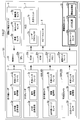
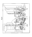
- DESCRIPTION OF SYMBOLS 1,100,101 ... Driving assistance device 2 ... Infrared radar, 3 ... Millimeter group radar, 4 ... Infrared camera, 5 ... Visible light camera, 6 ... Momentum amount detection unit, DESCRIPTION OF SYMBOLS 7 ... Head-up display (HUD), 8 ... Image projector, 9 ... Speaker unit, 10 ... Gaze detection unit, 11 ... Inter-vehicle communication unit, 12 ... Vehicle position sensor 20 ... Control ECU.
- the driving support apparatus 1 of the first embodiment includes an infrared radar 2, a millimeter wave radar 3, an infrared camera 4, a visible light camera 5, a momentum detection unit 6, and a head.
- An up display 7, a speaker unit 8, and a control ECU 20 are provided.
- FIG. 1 the image projector 9, the gaze detection unit 10, the inter-vehicle communication unit 11, and the vehicle position sensor 12 are shown.
- the driving assistance apparatus 1 is provided based on FIG.1 and FIG.2.
- the infrared radar 2 is a radar that detects the surrounding situation using infrared rays (in other words, detects the presence / absence of an object (hereinafter referred to as an object) and the distance to the object).
- the infrared radar 2 includes an infrared transmission / reception unit 2a, a signal processing unit 2b, and an external interface 2c.
- the infrared radar 2 irradiates infrared rays at the infrared transmission / reception unit 2a, and receives reflected light that is reflected by the object and returned.
- the signal processing unit 2b calculates the distance to the object based on the time difference between the irradiation time of the infrared rays and the reception time of the reflected light. Data representing the calculated distance is transmitted to the control ECU 20 via the external interface 2c.
- the distance that can be detected by the infrared radar 2 is about several tens of meters (for example, 20 to 30 m).
- the infrared radar 2 may be provided in a side part and a rear part in addition to the front part of the vehicle, as shown in FIG.
- the millimeter wave radar 3 is a radar that detects surrounding conditions using millimeter wave radio waves. As shown in FIG. 2, the millimeter wave radar 3 includes a millimeter wave transmission / reception unit 3a, a signal processing unit 3b, and an external interface 3c.
- the millimeter radar 3 receives the reflected wave that is reflected by the object and irradiated with the millimeter wave by the millimeter wave transmitting / receiving unit 3a. Then, the signal processing unit 3b calculates the distance to the object based on the time difference between the irradiation time of the millimeter wave and the reception time of the reflected wave. Data representing the calculated distance is transmitted to the control ECU 20 via the external interface 3c.
- the distance detectable by the millimeter wave radar 3 is up to about 150 m (or more). A resolution of about several tens of cm to 1 m is known.
- an object at a short distance up to several tens of meters
- a long distance from several tens of meters to 150 m (or more) is detected by the millimeter wave radar 3. Configured to detect the object.
- the infrared camera 4 is a camera that detects surrounding conditions by detecting infrared rays emitted from an object.
- the infrared camera 4 includes an infrared image sensor 4a, an image processing unit 4b, and an external interface 4c.
- the infrared camera 4 detects light (infrared rays) in the infrared region with the infrared image sensor 4a.
- the image processing unit 4b converts the infrared wavelength and intensity detected by the infrared image sensor 4a into an electrical signal, and generates an image based on the electrical signal.
- Data representing the generated image is transmitted to the control ECU 20 via the external interface 4c.
- this infrared camera 4 forms an image by detecting infrared rays emitted from an object, the object can be detected even in the absence of ambient light (such as sunlight) or headlight light. Therefore, the object can be detected even at night.
- the infrared camera 4 two infrared cameras 4A and 4B arranged at different positions are provided.
- the parallax difference in image position and viewing direction
- the infrared camera 4A and the infrared camera 4B Based on the fact that the parallax is correlated with the distance to the object, the distance to the object can be calculated according to the parallax.
- the infrared camera 4 refers to both the infrared cameras 4A and 4B unless otherwise specified.
- the visible light camera 5 is a camera that detects surrounding conditions by detecting reflected light of ambient light and headlight light.
- the visible light camera 5 includes a CCD image sensor 5a as an imaging device, an image processing unit 5b, and an external interface 5c.
- the visible light camera 5 detects light by the CCD image sensor 5a, and photoelectrically converts light and darkness of the detected light into a charge amount.
- the charge amount data is transferred to the image processing unit 5b.
- the image processing unit 5b generates a color image by reproducing color and brightness based on the charge amount data for each pixel.
- the generated image information is transmitted to the control ECU 20 via the external interface 5c.
- the visible light camera 5 is provided with two visible light cameras 5A and 5B arranged at different positions.
- the parallax is reproduced by the visible light camera 5A and the visible light camera 5B, and thereby a three-dimensional image can be generated. Further, as in the case of the infrared camera 4 described above, the distance to the object can be calculated.
- the momentum detection unit 6 is a unit for detecting the momentum of the host vehicle, and includes a vehicle speed sensor 6a, a yaw rate sensor 6b, and a steering angle sensor 6c.
- the traveling speed of the host vehicle is detected by the vehicle speed sensor 6a
- the yaw rate acting on the host vehicle is detected by the yaw rate sensor 6b
- the steering angle of the steering wheel is detected by the steering angle sensor 6c.
- the detection signal is transmitted to the control ECU 20.
- a head-up display (HUD: Head Up Display) 7 is a device that superimposes and displays an image on a vehicle window (in the example, a front window).
- the HUD 7 has a laser projector 7a, performs signal processing by the laser projector 7a based on a signal from the control ECU 20, generates an image, and displays the image via an optical unit 7b including a mirror and a lens. .
- the image is formed on the virtual image plane so as to be superimposed on the scenery outside the vehicle viewed through the front window.
- the virtual image plane is formed in front of the front window, so that the driver of the vehicle can recognize that the image is displayed in the viewable scenery.
- the speaker unit 8 is a device that emits sound (including sound) around the vehicle based on control by the control ECU 20.
- the control ECU 20 is an electronic control device that includes a CPU 20a, a ROM 20b, a RAM 20c, a flash memory 20d, a communication interface 20e, and the like, and executes various processes.
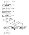
- the control ECU 20 repeatedly executes the driving support process of FIG. 3 at a predetermined cycle while the vehicle is traveling. Accordingly, the driving support device 1 detects the environment around the vehicle, recognizes an object (person, vehicle, etc.), and notifies the vehicle driver of the presence of the object (in other words, gives a warning).
- the driving support device 1 detects the environment around the vehicle, recognizes an object (person, vehicle, etc.), and notifies the vehicle driver of the presence of the object (in other words, gives a warning).
- detection data is acquired from the momentum detection unit 6, and the momentum of the host vehicle is estimated based on the acquired vehicle speed, yaw rate, and steering angle.
- a signal from the infrared radar 2 is acquired.
- the process proceeds to S112, and a signal from the millimeter wave radar 3 is acquired.
- S114 based on the signal from the infrared radar 2 and the signal from the millimeter wave radar 3, it is determined whether or not an object exists in the detection range.
- the process proceeds to S116 to store a log indicating that the object does not exist, and then the process is terminated. This log may be stored in the flash memory 20d.
- S118 based on the distance data to the object obtained from the infrared radar 2 signal and the millimeter wave radar 3 signal, it is determined whether or not the distance to the object is equal to or less than a preset threshold value ⁇ .
- the threshold value ⁇ is appropriately set to a value that causes a risk of collision.
- a fixed value may be set as the threshold value ⁇ .
- a value that is determined to cause a collision risk in relation to the host vehicle traveling at the momentum is calculated by calculation. It may be set.
- processing for warning the driver of the vehicle is executed.
- the HUD 7 is controlled to display a warning superimposed on, for example, the front window of the vehicle.
- a warning display a message or a symbol indicating that there is a risk of collision may be displayed.
- a collision avoidance command for avoiding a collision with the object is transmitted to an ECU (not shown) that controls the operation of the vehicle. Specifically, a collision avoidance command is transmitted to the brake control ECU, the steering control ECU, etc., and brake control and steering control for avoiding the collision are executed. Thereafter, the process ends.
- S124 image data is acquired from the infrared camera 4.
- either one of the image data of the infrared cameras 4A and 4B or both of them may be acquired.
- an average value of the two image data may be calculated and used.
- a highly accurate portion (a portion with less noise or the like) may be extracted from each of the two image data, and data combining them may be generated and used.
- image data is acquired from the visible light camera 5.
- image data of the visible light cameras 5A and 5B may be acquired, or both may be acquired.
- an average value of the two image data may be calculated and used.
- a highly accurate portion (a portion with less noise or the like) may be extracted from each of the two image data, and data combining them may be generated and used.
- processing for recognizing and analyzing the object (hereinafter, recognition processing) is executed. Details of the recognition process will be described later.
- S130 a display process for displaying information on objects around the vehicle based on the result of the recognition process in S128 is executed. In other words, this process is a process of notifying the driver of the presence of the object by displaying a predetermined image. Details of the display process will be described later.
- the process proceeds to S142, and an edge in the image (a portion where the amount of change in luminance (brightness / darkness) is larger than a predetermined threshold) is extracted.
- This process is based on the premise that the amount of change in luminance becomes large at the boundary between, for example, a person or a vehicle and the background.
- candidates for areas occupied by the same object are set based on the edge information extracted in S142. For example, as described above, it is assumed that the amount of change in luminance is large at the boundary between a person or vehicle and the background, but the amount of change in luminance is not always large at all boundaries, and the edges may be interrupted. obtain. In this processing, the range (area) of the same object determined by the edge is set (estimated) while recognizing the break of the edge from the data of the peripheral edge.
- the process proceeds to S146, and pattern matching is performed on the region set in S144 (more specifically, on the estimated object) with a pattern stored in advance and a past learning value (learned pattern), and the object Estimate what is In this pattern matching, a person (including a person riding a bicycle or the like), a vehicle, an animal (pet or the like), and an installation (a guardrail, a sign, a traffic light, a signboard or the like) can be recognized.
- S150 it is determined whether or not to notify the driver of the own vehicle of the extracted vehicle information (whether or not to warn). For example, it may be configured to be able to set in advance whether or not to notify the driver of the vehicle of vehicle information. And in S150, you may determine based on the setting. Alternatively, the positional relationship between the vehicle and the host vehicle, the relative speed, and the like may be detected, and the risk may be determined based on the detected position.
- warning display data is generated based on the analysis processing result in S152 and the determination result in S150.
- the data generated here is used in the display process in S130. Specifically, in S130, the data generated in S154 is transmitted to the HUD 7, and a warning image is displayed on the HUD 7.
- the analysis processing in S152 will be specifically described with reference to FIGS.
- the analysis processes 1 to 7 in FIGS. 5 to 12 (and FIG. 13) are executed in parallel or sequentially in a predetermined order.
- the analysis processes 1 to 7 are executed for each object recognized as “person” in S148 described above.
- a warning level for the object (person) is set according to the analysis result.
- the alert level is data used in the process of S154. Specifically, it is data for determining in what manner the warning is displayed to the driver of the vehicle.
- the alert level is represented by a numerical value. As the numerical value increases, display data is generated so that a warning is displayed in a manner that is more easily recognized by the driver of the vehicle.
- the analysis process 1 in FIG. 5 is a process of analyzing a position (location) where an object (person) exists and setting a warning level according to the position.
- a process for analyzing the position where the object (person) exists is executed. Specifically, the distance from the host vehicle, the relative position with respect to other objects, and the like are analyzed by image analysis of a captured image by the infrared camera 4 or the visible light camera 5. The distance from the host vehicle can be calculated using the parallax of the infrared cameras 4A and 4B or the parallax of the visible light cameras 5A and 5B.
- the signal from the infrared radar 2 acquired in S110 and the signal from the millimeter radar 3 acquired in S112 include information on the distance to the object.
- the distance calculated in S160 may be calculated or corrected.
- the distance may be calculated from the signals acquired in S110 and S112. After S160, the process proceeds to S162, and it is determined whether an object (person) exists on the traveling route of the host vehicle.
- the road on which the host vehicle is traveling is recognized by image analysis at the stage of the processing of S160 described above. Further, for the process of S170 described later, a sidewalk may be added and recognized.
- the movement direction (traveling direction) of the host vehicle is estimated based on the data on the amount of movement of the host vehicle acquired in S100. Based on these processes, it is determined whether or not the object (person) exists on the recognized road and on the estimated traveling direction of the own vehicle, so that the object (person) Determine if it exists above.
- the process proceeds to S164.
- the value of the alert level for the object (person) is incremented by 3 points. Thereafter, the process ends.
- the value of the alert level is incremented in the range of 1 to 3.
- “+0” is described in the flowchart. This value is an example, and any value may be set as appropriate.
- the numerical value of the alert level is stored in the flash memory 20d in association with the object (person). If it is determined in S162 that the object (person) does not exist on the travel route of the host vehicle, the process proceeds to S166.
- S166 it is determined whether or not the object (person) exists on the road on which the host vehicle is traveling. If it is determined in S166 that the object (person) exists on the road, the process proceeds to S168.
- S170 it is determined whether an object (person) exists on the sidewalk. If it is determined in S170 that the object (person) exists on the sidewalk, the alert level is incremented by one point.
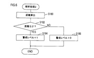
- the analysis process 2 will be described with reference to FIG.
- the analysis process 2 in FIG. 6 is a process of calculating the distance from the host vehicle to the object (person) and setting the alert level according to the calculated distance.
- the distance from the own vehicle to the object (person) is calculated.
- the calculation method is as described above.
- the process proceeds to S182, and it is determined whether or not the distance calculated in S180 is equal to or less than a predetermined threshold value ⁇ .
- the value of ⁇ can be set as appropriate.
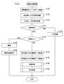
- the analysis process 3 will be described with reference to FIG.
- the analysis process 3 in FIG. 7 is a process for analyzing whether or not an object (person) is carrying and operating a portable terminal (and whether or not the vehicle is recognized) and setting a warning level based on the result. It is.
- the analysis process 3 first, in S190, it is determined whether or not the object (person) is carrying (gripping) the portable terminal.
- the presence / absence (presence) of the portable terminal is recognized by image analysis (pattern matching) in the processing of S140 to S146 described above.
- image analysis pattern matching
- the luminance (brightness) of the display screen portion is high, and edge extraction with relatively high accuracy is possible.
- recognition by pattern matching becomes easy.
- edge extraction can be performed based on a difference in luminance (brightness and darkness) from a human hand when the portable terminal is held by the human hand. Therefore, in any case, recognition by pattern matching is possible.
- S190 if it is determined in S190 that the object (person) is carrying (holding) the portable terminal, the process proceeds to S194.
- S194 it is determined whether or not the mobile terminal is operating.
- the mobile terminal is operating from the brightness (brightness and darkness) in the area recognized as the mobile terminal. This is intended to make a determination on the assumption that the luminance (brightness) of the portion of the display screen in the portable terminal is high when the portable terminal is in operation.
- the process proceeds to S196.
- the alert level is incremented by 1 point based on the determination that the object (person) is holding the mobile terminal although the mobile terminal is not operating. Thereafter, the process is terminated.
- the process proceeds to S198. Note that the process of S194 may be omitted. Specifically, if it is determined in S190 that the object (person) is carrying (gripping) the portable terminal, the process may proceed to S198 without executing the process of S194.
- S198 it is determined whether or not the object (person) is operating the mobile terminal.
- the position of the portable terminal, the position of each part (hand, face) in the object (person), the orientation of the face, and the like are analyzed and comprehensively determined from the information.
- S198 If it is determined that the operation is not being performed in S198, the process proceeds to S196. On the other hand, if it determines with operating in S198, it will transfer to S200. In S200, a process of determining whether or not the object (person) recognizes the presence of the host vehicle (hereinafter, a recognition determination process) is executed.
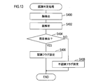
- FIG. 13 shows the recognition determination process.
- the recognition determination process in S200 recognition determination process in FIG. 13
- a face area in the object (person) is extracted.
- step S404 it is determined whether both eyes have been detected.
- a recognition flag indicating that the object (person) recognizes the presence of the host vehicle is set. Thereafter, the process is terminated. On the other hand, if it is determined in S404 that both eyes cannot be detected, it is determined that the host vehicle may not exist within the field of view of the object (person). Based on this determination, the object (person) A simple determination is made that the presence of the vehicle is not recognized, and the flow proceeds to S408.
- a determination process based on the recognition flag set in S406 or the non-recognition flag set in S408 (specifically, a determination process as to whether or not the object (person) recognizes the presence of the host vehicle). )I do.
- the process proceeds to S204.
- the alert level is incremented by 2 points based on the determination that the object (person) recognizes the existence of the own vehicle while the portable terminal is being operated. Thereafter, the process is terminated.
- the process proceeds to S206.
- the alert level is incremented by 3 points based on the determination that the object (person) is operating the mobile terminal and does not recognize the presence of the host vehicle.
- the warning setting process includes a flag for displaying an image for notifying (warning) the driver that the object (person) has not recognized the existence of the own vehicle, and an alarm process for the object (person). This is a process of setting a flag to the effect. This flag is stored in association with the target object (person).
- a warning image for notifying (warning) the driver that the object (person) has not recognized the presence of the own vehicle is generated.
- the vehicle is superimposed and displayed on the front window.
- an alarm is issued to the object (person) through the speaker unit 8 (see FIGS. 1 and 2) by a separate process.
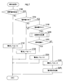
- the analysis process 4 in FIG. 8 is a process of analyzing whether or not the object (person) is using the headphones (and whether or not the vehicle is recognized), and setting a warning level based on the result. .
- S210 it is determined whether or not the object (person) is using headphones or earphones (hereinafter simply referred to as headphones).
- the determination is made based on the result of image analysis (the processing of S140 to S146).
- the process proceeds to S218.
- the alert level is incremented by 1 point based on the determination that the object (person) recognizes the presence of the host vehicle and uses the headphones. Thereafter, the process is terminated.
- the process proceeds to S220.
- the warning level is incremented by 3 points based on the determination that the object (person) is using headphones and does not recognize the presence of the host vehicle.
- the analysis process 5 in FIG. 9 is a process for analyzing whether or not the object (person) is talking or talking (and whether or not the vehicle is recognized) and setting a warning level based on the result. is there.
- the analysis process 5 first, in S230, it is determined whether or not the object (person) is talking or talking. Here, the determination is made based on the result of image analysis (the processing of S140 to S146).
- the process proceeds to S238.
- the alert level is incremented by 1 point based on the determination that the object (person) recognizes the presence of the own vehicle while talking or talking. Thereafter, the process is terminated.
- the process proceeds to S240.
- the alert level is incremented by 3 points based on the determination that the object (person) is talking or talking and does not recognize the presence of the vehicle.
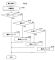
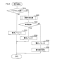
- the analysis process 6 in FIG. 10 is a process of analyzing the movement of an object (person) and setting a warning level based on the result.
- image data is re-acquired from the infrared camera 4 or the visible light camera 5 in S250.
- tracking processing between a plurality of images (between frames) is executed for the object (person). Specifically, the similarity of objects (people) is calculated in the current image (current frame) and the image (frame) in the past, and objects (people) with high similarity are the same object (people). The same label is assigned because it is determined that there is a high possibility that As the similarity index, the size (area) of the region, luminance (brightness / darkness), movement amount, and the like are used. Here, the size (area) of the object (person), the amount of movement, and the like are corrected in consideration of the amount of movement of the host vehicle. The objects (people) with the same label are analyzed in time series, and the presence / absence of movement and the movement direction are calculated.
- the process proceeds to S256, and it is determined whether or not the movement of the object (person) can be analyzed. In other words, it is determined whether the re-acquired image data and exercise amount data are sufficient for recognizing or estimating the movement of the object (person).
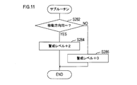
- FIG. 11 is a flowchart showing the flow of subroutine processing in S280.
- S280 subroutine processing of FIG. 11
- S282 it is determined whether or not the moving direction of the object (person) is the same as the moving direction of the host vehicle.
- the alert level is incremented by 2 points. Thereafter, the process is terminated.
- the process proceeds to S286, and then the process is terminated without incrementing the alert level.
- the process proceeds to S262 in FIG. In S262, it is determined whether or not the object (person) is meandering. As for the meanders, there are warnings about wobbling due to drinking, wobbling due to two-seater bicycles, and the like.
- the process proceeds to S264 based on the judgment that the object is not meandering but is moving, and the warning level is incremented by one point. Thereafter, the process is terminated.
- the process proceeds to S268 based on the determination that the object (person) is not approaching but is meandering, and the warning level is incremented by 2 points. Thereafter, the process is terminated.
- the process proceeds to S270, and the warning level is incremented by 3 points.
- the process proceeds to S272, and a flag for displaying an image indicating the moving direction of the object (person) is set.
- this flag is set, an image indicating the moving direction of the object (person) is generated in the process of S154 in FIG. 4, and the image is displayed in the process of S130 in FIG.
- This series of processing is executed with the purpose of calling attention to the driver of the vehicle by displaying an image indicating the moving direction of the object (person).
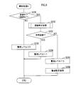
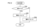
- the analysis process 7 will be described with reference to FIG.
- the analysis process 7 in FIG. 12 is a process for simply determining whether or not the object (person) is a child and setting a warning level based on the result.
- the height (height) of the object (person) is equal to or less than a predetermined threshold value Ta.
- a predetermined threshold value Ta an average height of a person (child) of an age to be discriminated may be assigned.
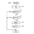
- processing for generating an image for emphasizing the object (person) is executed for each object (person) according to the extracted alert level.
- the enhanced image generation process will be specifically described with reference to FIG.
- S504 enhanced image generation process of FIG. 15
- S520 an image surrounding the object area is generated in accordance with the object area of each object (person).
- a triangle, a quadrangle, a circle, an ellipse, or the like can be set as appropriate.
- a vertically long image can be generated for a standing object (person), and an image with a substantially equal aspect ratio can be generated for a sitting object (person), for example.
- a horizontally long image is generated for an object (person) that has fallen down.
- the process proceeds to S522, and the display mode of the image generated in S520 is set according to the alert level extracted in S502 described above. Specifically, the thickness of the frame line, the color of the line, etc. are set. It is also set whether to blink display.
- the higher the alert level the thicker the line.
- the line color may be set to a color (red, yellow, other fluorescent color, etc.) that attracts the driver's attention.
- the image may be set to blink.
- Each object (person) may be classified as a group with a high point, an intermediate group, or a low group according to the set alert level point. And the display mode of an image may be set for every group.
- S524 it is determined whether images have been set for all objects (people). If it is determined in S524 that no image has been set for all objects (persons) (an unset object (person) exists), the process returns to S520 (and S522).
- a flag for warning the vehicle (hereinafter, vehicle warning flag) is set. This flag is set in the process of S156 in FIG. If it is determined in S506 that the vehicle warning flag is set, the process proceeds to S508, and an image for emphasizing the object (vehicle) is generated in association with the target object (vehicle). Specifically, an image surrounding the object area of the object (vehicle) recognized in the processes of S140 to S148 in FIG. 4 is generated. As an image surrounding the object region, a triangle, a quadrangle, a circle, an ellipse, or the like can be set as appropriate. After the processing of S508, the process proceeds to S510.
- S510 whether or not a flag (hereinafter referred to as an unrecognized notification flag) for displaying an image for notifying (warning) the driver that the object (person) has not recognized the presence of the host vehicle is set. Determine whether. This flag is set in the processing of S208 in FIGS.
- a warning image for the driver is generated in association with the target object (person).
- This warning image is an image for notifying (warning) the driver that the object (person) has not recognized the presence of the own vehicle.
- the image is not limited to a mark such as a symbol, but may be a message, for example. Alternatively, an image surrounding the face portion of the object (person) may be used.
- the color of the warning image may be a color (red, yellow, other fluorescent color, etc.) that further prompts the warning.
- S510 If it is determined in S510 that the unrecognition notification flag is not set, the process proceeds to S514. In S514, it is determined whether or not a flag for displaying an image indicating the moving direction of the object (person) (hereinafter referred to as a moving display flag) is set. This flag is set in the process of S272 of FIG.
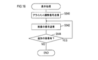
- an alignment adjustment signal for initializing and adjusting the display position and the imaging position by the HUD 7 is transmitted to the HUD 7. This causes the HUD 7 to execute adjustment (initialization) of the display position and the imaging position.
- a signal representing an image generated in the display data generation process of S154 (display data generation process shown in FIGS. 14 and 15) is transmitted to the HUD 7.
- the image is superimposed and displayed on the front window of the vehicle via the HUD 7.
- the signal representing the image includes data of coordinate values (coordinate values based on the display area by the HUD 7) at which the image is to be displayed.
- control ECU 20 includes information on coordinate axes (hereinafter referred to as camera coordinate axes) based on the imaging areas of the infrared camera 4 and the visible light camera 5 and coordinate axes (hereinafter referred to as HUD coordinate axes) based on the display area of the HUD 7. Have both information. Then, the coordinate value (the coordinate value indicating the position to be displayed by the HUD 7) on which the image generated by the image analysis of the infrared camera 4 or the visible light camera 5 is to be displayed is changed from the coordinate value on the camera coordinate axis on the HUD coordinate axis. Calculated by converting to coordinate values.
- coordinate axes hereinafter referred to as camera coordinate axes
- HUD coordinate axes coordinate axes
- S542 the process proceeds to S544, and it is determined whether there is an additional display image. Specifically, it is determined whether or not a new image is generated by the display data generation process of S154. If it is determined in S544 that there is an additional image, the process of S542 is executed again.
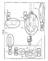
- FIG. 17 First, the example of FIG. 17 will be described.
- an object H that is a person and objects V0, V1, and V2 that are vehicles are extracted and recognized.
- an image for emphasis is superimposed and displayed for both a person and a vehicle.
- an oval frame image (hereinafter also simply referred to as a frame) W surrounding the object H is displayed.
- a frame an oval frame image
- elliptical frames X0, X1, and X2 that surround the objects V0, V1, and V2 are displayed.
- the display mode may be different between the frame W and the frames X0, X1, and X2.
- the frame W may be displayed as a solid line
- the frames X0, X1, and X2 may be displayed as a broken line.
- the object V0 and the object V2 are seen partially overlapping (part of the object V2 is behind the object V0).
- the positional relationship between the object V0 and the object V2 may be grasped from the stereoscopic information (depth information).
- the control ECU 20 is configured not to recognize the object V0 and the object V2 as different objects based on the three-dimensional information (depth information) but as different objects.
- a frame X0 corresponding to the object V0 and a frame X2 corresponding to the object V2 are drawn.
- the frame X0 and the frame X2 may also include stereoscopic information (depth information).
- the frame X2 may be displayed so that a part of the frame X2 is hidden behind the object V0.
- a mode display area R is shown at the upper right of the drawing. This area is an area for displaying a target for displaying an image for emphasis (specifically, a target symbol mark).
- a vehicle symbol Mv and a human symbol Mp are shown in the mode display area R. This indicates a mode in which an image for emphasis (frame W and frames X0, X1, and X2 in FIG. 17) is displayed for the vehicle and the person.
- an image (frame W) for detecting an object (person, other vehicle) or the like around the host vehicle and causing the driver to visually recognize the detected object is displayed on the object. It is superimposed and displayed in association. For this reason, it is easier for the driver to recognize the object.
- FIGS. 18A and 18B Next, an example of FIGS. 18A and 18B will be described.
- the driving support device 1 analyzes the state of each person by image analysis for each of the four persons, and displays a warning image corresponding to the analyzed state.
- a frame W (W1, W2, W3, W4) for emphasis is displayed for each of the objects H1 to H4.
- the frame W may be generated and displayed so as to surround the areas of the objects H1 to H4.
- the frame W may be configured to be generated and displayed vertically.
- the frame W may be configured to be generated and displayed horizontally.
- the frame W may be generated and displayed so that the aspect ratio of the frame W is approximately equal.
- the display modes of the frames W1 to W4 differ depending on the alert level.
- the objects H1 and H2 exist in the travel route of the host vehicle. In particular, it is assumed that the distance from the host vehicle is equal to or less than a predetermined threshold value ⁇ for the object H1.
- the frame W1 is displayed in a display mode that is more emphasized.
- the frame W1 may be configured with a double frame. Further, it may be displayed in a more conspicuous color such as a fluorescent color.
- the distance from the host vehicle is greater than a predetermined threshold ⁇ for the object H2. Accordingly, when the alert level is set relatively low (compared to the object H1) for the object H2, the degree of emphasis of the frame W2 may be suppressed in comparison with the frame W1.
- the frame W2 may be displayed blinking, for example.
- the driving support apparatus 1 determines that the objects H1 and H2 are in conversation, the driving support apparatus 1 displays the conversation symbols M1 and M2 indicating that the objects are in conversation in the vicinity of the frames W1 and W2 in association with the objects H1 and H2. You may do it.
- Data of conversation symbols M1 and M2 is stored in the flash memory 20d. Note that the data of the conversation symbols M1 and M2 may be stored in the ROM 20b. The same applies to a portable terminal symbol M3, a headphone symbol M4, an unrecognized symbol M1 ′, and a recognized symbol M2 ′ described later.
- the vicinity is a position adjacent to (or in contact with) the frame W regardless of whether it is up, down, left, or right with respect to the frame W.
- it may be within the area of the frame W.
- the conversation symbols M1 and M2 may be displayed superimposed on the areas of the frames W1 and W2. The meaning of “near” is the same in the following.
- an unrecognized symbol M1 ′ representing that fact may be superimposed on the vicinity of the frame W1 in association with the object H1.
- a recognition symbol M2 ′ representing that fact is superimposed on the vicinity of the frame W2 in association with the object H2. You may display.
- a mobile terminal symbol M3 indicating that may be displayed in a superimposed manner in the vicinity of the frame W3 in association with the object H3.
- the headphone symbol M4 indicating that may be displayed in the vicinity of the frame W4 in association with the object H4.
- the driving support device 1 may set an auxiliary display area P1 for displaying auxiliary information.
- the number of extracted objects may be displayed in the auxiliary display area P1.
- the number of persons displayed in the auxiliary display area P1 may be the number of persons displaying an image for emphasis.
- the numerical value of the number of people may be incremented according to the addition.
- the numerical value of the number of people may be decremented and displayed in accordance with the erase. Further, when the number of people is the same but the object is changed, the fact may be notified by flashing a numerical value or the like.
- the symbols M1 to M4, M1 ′, and M2 ′ may be deleted or changed according to changes in the states of the objects H1 to H4.
- the driving support device 1 when the object is a person, information indicating the state of the person is displayed, so the driver recognizes not only the presence of the person but also the state of the person. become able to. For this reason, it becomes possible for the driver to realize driving according to the conditions of people around the vehicle. That is, it can contribute to improving driving safety.
- FIG. 19 Next, the example of FIG. 19 will be described.
- four objects H5, H6, H7, and H8 are extracted.
- Objects H5 and H6 are pedestrians walking on a pedestrian crossing, and objects H7 and H8 are people riding bicycles.
- Objects H5, H6, H7, and H8 are surrounded by frames W5, W6, W7, and frame 8 for emphasis, respectively.
- the display mode of W5, W6, W7, and the frame 8 may be different depending on the distance from the host vehicle to the objects H5, H6, H7, and H8, for example.
- the line thickness may be different.
- the object H5 is closest to the own vehicle, and the frame 5 corresponding to the object H5 is displayed with the thickest line.
- the object H8 is farthest from the host vehicle, and the frame 8 corresponding to the object H8 is displayed by the thinnest line.
- an arrow image (hereinafter, also simply referred to as an arrow) Y indicating the traveling direction of the object is displayed in association with each object H.
- arrows Y5 and Y7 are directed to the right side in the drawing, indicating that the objects H5 and H7 are traveling toward the right side.
- An arrow Y6 is directed toward the left side in the drawing, and indicates that the object H6 is traveling toward the left side.
- the arrow Y8 is directed toward the own vehicle, indicating that the object H8 is approaching the own vehicle.
- the arrow Y may indicate the moving speed of each object H.
- the magnitude of the moving speed may be indicated by the length of the arrow Y.
- arrows Y5, Y6, and Y7 whose lengths are easily compared are targeted.
- the length of the arrow Y7 is the longest and the moving speed of the object H7 is the highest.
- the arrow Y6 is the shortest and the moving speed of the object H6 is the lowest.
- the length of the arrow Y5 is intermediate between the arrows Y7 and Y6, and the moving speed of the object H5 is between the moving speed of the object H7 and the moving speed of the object H6.
- arrow gradation portions G5, G6, G7 may be drawn, and the magnitude of the moving speed may be indicated by the length, density, etc. of the gradation portions.
- the magnitude of the moving speed may be indicated by the position of the arrow Y with respect to the frame W (or the object H).
- arrows Y5, Y6, and Y7 that can be compared in the height direction with respect to the frame W (or the object H) are targeted.
- the arrow Y7 is shown further upward in the range in the height direction of the frame W7 (and the object H7).
- the arrow Y5 is shown around the middle in the range in the height direction of the frame W5 (and the object H5).
- the arrow Y6 is shown below in the range in the height direction of the frame W6 (and the object H6).
- the moving speed of the object H7 is the highest at the position of the arrow Y7 (the position in the vertical direction) shown above in relation to the object H. Further, it may be indicated that the moving speed of the object H6 is the lowest at the position of the arrow Y6 (vertical direction position) shown below in relation to the object H. In addition, even if the position of the arrow Y5 (vertical direction position) indicated at an intermediate position in relation to the object H indicates that the moving speed of the object H5 is intermediate between the object H7 and the object H6. good.
- the driving support device 1 since the information indicating the direction in which the person around the vehicle is moving and the moving speed thereof is displayed, it is easy for the driver to predict the movement of the person. For this reason, it can contribute to improving the safety of driving.
- the example of FIG. 20 is a display example at night.
- the object H9 is extracted and recognized.
- a frame W9 for emphasizing the object H9 is superimposed and displayed.
- the frame W9 may be drawn with a white color or a fluorescent color so that the frame W9 is easily visible at night.
- an arrow symbol M9 is displayed to enhance the effect of attracting the driver's attention.
- the arrow symbol M ⁇ b> 9 faces the object H ⁇ b> 9 rather than the moving direction of the object H ⁇ b> 9 and strengthens the presence of the object H ⁇ b> 9.
- the arrow symbol M9 is arranged so that when the line of sight is moved in the direction of the arrow, the object H9 is naturally recognized (so that it comes to the center of the field of view).
- the driving support device 1 may be configured to display the frame W9 and the arrow symbol M9 at the same time when the object H9 is detected.
- the frame W9 may be displayed and the arrow symbol M9 may be additionally displayed after a predetermined time has elapsed. According to the latter configuration, the enhancement effect can be further enhanced.
- a caution symbol M9 ' is displayed on the left side of the frame W9.
- the attention symbol M9 ' can also be displayed to enhance the effect of attracting the driver's attention, like the arrow symbol M9.
- the display position of the attention symbol M9 '(and the arrow symbol M9) may be any position as long as it is easily recognized in relation to the background.
- the frame W9 (and the object H)) may be displayed in the lower left area Ra.
- it may be displayed in the region Rb directly below the frame W9 (and the object H)).
- the background is displayed in a region where the luminance (brightness / darkness) does not vary (in other words, a region where the luminance (brightness / darkness) is constant).
- auxiliary display areas P2 to P4 may be set.
- a symbol mark h9 representing the object H9 is displayed in the auxiliary display area P2.
- the symbol mark h9 may be displayed in the auxiliary display area P2.
- Such a mode may be set by the driver using an input device operated by the driver.
- the distance is displayed in the auxiliary display area P3. This distance represents the distance from the host vehicle to the object H9.
- a symbol m9 that is the same symbol as the attention symbol M9 ′ is displayed.
- the attention symbol M9 ′ and the symbol m9 may be displayed in conjunction with each other. For example, the symbol m9 may be automatically displayed when the attention symbol M9 ′ is displayed. Further, when the attention symbol M9 ′ is deleted, the symbol m9 may also be deleted.
- the driving assistance device 1 it is possible to appropriately support the driver visually recognizing the surrounding situation at night or the like when the visibility is lowered for the driver. For this reason, it can contribute to improving driving safety even at night.
- the infrared radar 2, the millimeter radar 3, the infrared camera 4, and the visible light camera 5 correspond to an example of a detection unit
- the processes of S114, S128, and S140 to S148 correspond to an example of a recognition unit.
- the processing of S152 corresponds to an example of analysis means, and S164, S168, S172, S174, S184, S186, S192, S196, S204, S206, S208, S212, S218, S220, S232, S238, S240, S260,
- the processing of S264, S268, S270, S284, S286, S292, S294, and S660 corresponds to an example of a setting unit
- the processing of S154 corresponds to an example of a generation unit
- the processing of HUD7 and S130 corresponds to an example of a display unit. To do.
- the process of S148 corresponds to an example of a determination unit
- the ROM 20b or the flash memory 20d corresponds to an example of a storage unit.
- the conversation symbols M1, M2, the mobile terminal symbol M3, and the headphone symbol M4 correspond to examples of symbolic symbols.
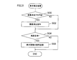
- the driving support device 100 (see FIG. 21) of the second embodiment is different from the driving support device 1 (see FIG. 2) of the first embodiment in that an image projecting device 9 is provided.
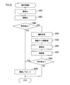
- the driving support device 100 is different from the driving support device 1 in the following points. First, instead of the recognition process of FIG. 4, the recognition process (2) of FIG. 22 is executed.
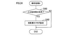
- the analysis process 8 of FIG. 24 is performed. Further, instead of the display process of S130 in FIG. 3 (display process of FIG. 16), the display process (2) of FIG. 25 is executed.
- the image projecting device 9 is a device for projecting an image to an area in an environment outside the vehicle, which can project an image as a screen.
- a region where an image can be projected as a screen can be detected by analyzing an image captured by the infrared camera 4 or the visible light camera 5.
- the image projector 9 has a laser projector 9a, performs signal processing by the laser projector 9a based on a signal from the control ECU 20 (in other words, generates a display image signal), and includes an optical system including a mirror, a lens, and the like. An image is projected through the unit 9b.
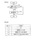
- the screen determination process is a process for determining whether or not an image can be projected onto the area of the object determined to be “other”.
- the control ECU 20 first determines whether or not the area of the object region is equal to or larger than the predetermined area S in S560.
- This process is a process for determining whether or not the image has a sufficient area (area) for projecting an image.
- S562 it is determined whether the distance from the host vehicle to the object is a distance at which an image can be projected. If it is determined in S562 that the distance is not projectable, the process ends.
- the difference and variation in the brightness (brightness and darkness) of the image increases as the degree of unevenness of the surface of the object region increases.
- the smaller the unevenness of the surface of the object area the smaller the difference and variation in the luminance (brightness) of the image.
- the flatness is estimated by analyzing the difference (brightness and darkness) in the luminance (brightness and darkness) of the image of the object region.
- the process proceeds to S566, and it is determined whether or not the estimated flatness is equal to or less than a predetermined threshold F (assuming that the smaller the flatness value is, the flatter it is). If it is determined in S566 that the flatness is not less than or equal to the predetermined threshold value F, the process is terminated.
- a predetermined threshold F assuming that the smaller the flatness value is, the flatter it is.
- the characteristic that the absorption rate of infrared rays varies depending on the color of the surface irradiated with infrared rays is used.
- White objects have a relatively low infrared absorption rate (in other words, infrared reflectance is relatively high.
- black objects have a relatively high infrared absorption rate (in other words, infrared reflectance). Is relatively low).
- the infrared absorption rate of the object can be calculated by analyzing the intensity of the reflected infrared light irradiated by the infrared sensor 2 in consideration of the distance to the object. Based on the calculation result, the color of the object can be estimated.
- the color of the surface of the object area is estimated using the infrared sensor 2 by the method described above. After S568, the process proceeds to S570, and based on the estimation result in S568, it is determined whether or not the color of the surface of the object region is a color capable of projecting an image.
- S570 If it is determined in S570 that projection is not possible, the process ends. On the other hand, if it determines with projection being possible in S570, it will transfer to S572. In S572, a flag (projectable flag) indicating that an image can be projected as a screen is set for the target object region.
- the control ECU 20 further executes an analysis process 8 as one of the analysis processes of S152 in FIG.
- FIG. 24 shows the flow of the analysis process 8.
- the control ECU 20 first determines in S580 whether or not a person exists in the blind spot of the vehicle (other vehicle) from the extracted positional relationship between the person and the vehicle. In this determination, the traveling direction of the other vehicle, the person and the objects (obstacles) around the other vehicle are extracted, and it is comprehensively determined whether or not the person exists in the view area of the driver of the other vehicle.
- S590 it is determined whether the projection enable flag and the projection execution flag are set.
- the projectable flag is a flag set in the above-described processing of S572 (see FIG. 23).
- the projection execution flag is a flag set in the process of S582 described above (see FIG. 24).
- the process proceeds to S592.
- the information (specifically, information on the coordinate value, range, area, etc.) of the object area that can be projected as a screen and stored in S574 is transmitted to the image projection device 9.
- image data to be projected on the image projection device 9 is transmitted to the image projection device 9.
- This image data may be a part or all of the data of the image captured by the infrared camera 4 or a part or all of the data of the image captured by the visible light camera 5.
- generated by the process (refer FIG. 22) of S154 may be included.
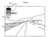
- the image projecting device 9 can project an image onto a predetermined region (region in which an image can be projected) in the environment around the vehicle. .
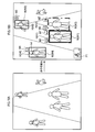
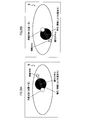
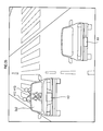
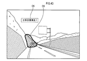
- the driving support apparatus 100 is mounted on a vehicle (own vehicle) K1. There is another vehicle K2 around the host vehicle K1. There are also objects H10 and H11.
- the object H10 is a bag and the object H11 is a person (here, a duo). In FIG. 26, only the top of one person's head is visible. When viewed from the direction of the other vehicle K2, the object H11 is hidden behind the object H10. That is, a positional relationship is formed in which the object H10 cannot be visually recognized by the driver of the other vehicle K2.
- the driving support device 100 of the host vehicle K1 detects the objects H10 and H11 by analyzing the image data of the infrared camera 4 or the image data of the visible light camera 5. Further, the other vehicle K2 is detected.
- a screen determination process is executed to determine whether an image can be projected as a screen. Further, the positional relationship between the objects H10 and H11 and the other vehicle K2 is analyzed, and it is determined whether or not the object H11 is within the field of view of the driver of the other vehicle K2.
- the driving support apparatus 100 transmits the image data of the object H11 to the image projection apparatus 9, and projects the image of the object H11 on a predetermined area (screen area that can project an image as a screen) Sc1 in the object H10. .
- the driver displayed on the screen area Sc1 of the object H10 indicates that the driver of the other vehicle K2 has the presence of the object H11. Can be recognized.
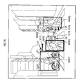
- the driving support device 101 (see FIG. 27) of the third embodiment is different from the driving support device 1 (see FIG. 2) of the first embodiment in that it includes a line-of-sight detection unit 10.
- the driving support device 101 is different from the driving support device 1 in that the driving support processing (2) in FIG. 29 is executed instead of the driving support processing in FIG.
- the line-of-sight detection unit 10 is a device that is mounted in a vehicle and detects the line of sight by tracking the movement of the eyeball (pupil) of the driver of the vehicle by image recognition.
- the line-of-sight detection unit 10 includes a CCD image sensor 10a, an LED light source 10b, and an image processing unit 10c.
- the LED light source 10b irradiates invisible near infrared rays. This near infrared ray is emitted toward the eyes of the driver. In this case, the near-infrared ray is reflected by the cornea of the eye, and the position of the reflection can be detected as a bright portion compared to the surroundings. Further, the reflection position has a feature that it maintains a constant position even if the line of sight changes (even if the position of the pupil changes).
- the line-of-sight detection unit 10 detects an eye image by the CCD image sensor 10a, and analyzes the eye image by the image processing unit 10c. In the image analysis, the above-described reflection position (near-infrared reflection position) in the cornea and the position of the pupil are detected.
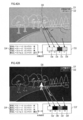
- FIGS. 28A and 28B show examples of image analysis.
- FIGS. 28A and 28B are schematic views showing examples of imaging of the driver's eyes.
- the line of sight (pupil position) is different.
- the pupil is darker in the eye than other parts, and the corneal reflection is brighter in the eye than other parts.
- the pupil and corneal reflection are detected and the positional relationship between them is analyzed using this feature.
- the corneal reflection appears at the most prominent part of the entire cornea and the position thereof is almost constant, and the direction of the line of sight is detected (estimated) from the positional relationship of the pupil with respect to the position of the corneal reflection.
- the direction of the line of sight may be estimated based on the direction connecting the center position of corneal reflection and the center position of the pupil.
- the direction of the line of sight may be estimated based on research data on the relationship between the position of corneal reflection, the position of the pupil, and the direction of the line of sight, past learning values, and the like.
- driving support processing (2) executed by the driving support device 101 will be described with reference to FIG.
- control ECU 20 indirectly determines whether or not the driver has recognized the warning image based on the detection result of the line-of-sight detection unit 10, and reconstructs the warning image based on the determination result ( Correction).
- the display correction process in S602 is a process in which the control ECU 20 corrects the display image based on the result of the correction determination process in S600.
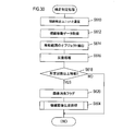
- the correction determination process will be specifically described with reference to FIG.
- control ECU 20 When the control ECU 20 starts the correction determination process of S600 (the correction determination process of FIG. 30), first, the control ECU 20 communicates with the line-of-sight detection unit 10 in S610. Next, the process proceeds to S612, and analysis data by the line-of-sight detection unit 10 (in other words, data indicating movement of the line of sight) is acquired.
- the process of S504 is the same as the process of S504 in FIG. In the emphasized image generation process of S504 in FIG. 30, except for the object (person) for which the flag for erasing the image to be emphasized is set, the other objects (persons) are newly processed in S520 to S524 (FIG. 15). ).
- an object (person) belonging to a group with a lower alert level is moved up to a group with a higher alert level, and an image with a higher alert level can be set.
- S634 it is determined whether or not the image display mode has been reset. In other words, it is determined whether or not the process of S504 in FIG. 30 has been executed. If it is determined in S634 that the image display mode has been reset (the process in S504 has been re-executed), the process proceeds to S636.
- a signal representing an image to be displayed is transmitted to the HUD 7 based on the processing result of S504 in FIG. Thereby, the image is superimposed and displayed on the front window of the vehicle via the HUD 7. Thereafter, the process ends.
- the driving support apparatus 101 displays an image that emphasizes objects around the vehicle in a superimposed manner on the front window, and determines whether the driver of the vehicle has recognized the image. Judgment is made by detecting the driver's line of sight. Then, the display of the image for which the determination result that the driver of the vehicle recognizes is obtained is stopped (in other words, deleted). Then, the display mode is reset. Thereby, another image (an image for emphasizing another object (person)) is further emphasized and displayed. In addition, an object (person) for which an image has not been set can be newly set and emphasized.
- the line-of-sight detection unit 10 corresponds to an example of a line-of-sight detection unit
- the process of S618 corresponds to an example of an identification unit
- the processes of S620 and S602 correspond to an example of an erasure unit.
- ⁇ Fourth embodiment> A fourth embodiment of the present invention will be described.
- the configuration of the driving support device is the same as the configuration of the driving support device 1 of the first embodiment (see FIG. 2).
- the fourth embodiment is different in that the recognition determination process (2) in FIG. 32 is executed instead of the recognition determination process in FIG.
- the recognition determination process (2) in FIG. 32 is different from the recognition determination process in FIG. 13 in that the processes of S650 to S658 are executed. Note that the processing of S400 to S408 is the same as the recognition determination processing of FIG.
- an alarm process for issuing an alarm to the object (person) is executed. Specifically, a process of emitting a predetermined sound (including sound) from the speaker unit 8 is executed. The alarm is issued to make the object (person) aware of the existence of the own vehicle. Also, it is issued to determine whether or not the object (person) has noticed the existence of the own vehicle. Note that an alarm may be given by turning on or blinking the headlamp of the vehicle.
- the process proceeds to S652, and the image data of the infrared camera 4 or the visible light camera 5 is acquired again.
- the face area of the same object (person) is re-extracted based on the image data reacquired in S652.
- step S656 the process proceeds to S656, and the extracted face is analyzed. More specifically, “eyes” are extracted by edge detection and pattern matching. In step S658, it is determined whether both eyes have been detected.
- the driving support device 1 issues an alarm to make the presence of the own vehicle noticeable.
- an object (person) can be made to recognize presence of the own vehicle.
- the danger (warning level) can be set appropriately in accordance with the state of the object (person). As a result, it is possible to display an image for warning the driver more appropriately.
- a fifth embodiment of the present invention will be described.
- the configuration of the driving support device is the same as the configuration of the driving support device 1 of the first embodiment (see FIG. 2).
- the fifth embodiment is different from the driving support device 1 of the first embodiment in that the analysis process 9 of FIG. 33 is further executed.
- the analysis process 9 will be specifically described.
- the processes of S400 to S404 in the analysis process 9 are the same as the processes of S400 to S404 in FIG. 13 (and the processes of S400 to S404 in FIG. 32). Further, the processing of S650 to S658 in the analysis processing 9 is the same as the processing of S650 to S658 in FIG. Description of these processes is omitted.
- the control ECU 8 executes the analysis process 9 in addition to the analysis processes 1 to 7 shown in FIGS. 5 to 12 (and FIG. 13) as the analysis process of S152 in FIG. 4, and in the analysis process 9, in S404 or S658 If it is determined that both eyes have been detected, the process proceeds to S660.
- the alert level is decremented by 2 points for the target object (person) determined to have detected both eyes.
- the numerical value of 2 points is an example, and any value may be used.
- the purpose of the process of S660 is that the object (person) can determine that the object (person) recognizes (or has noticed) the existence of the own vehicle by an affirmative determination in S404 or S658.
- the purpose is to lower.
- the warning level is lowered for the object (person) that recognizes the existence of the own vehicle, and thereby the other object (person) (for example, the existence of the own vehicle is recognized).
- the level of vigilance for objects (persons) that do not exist is relatively increased.
- a more emphasized image can be displayed for an object (person) to be more careful. Therefore, the presence of the object can be recognized more effectively or efficiently by the driver.
- Modification 1 will be described with reference to FIG. 34, the objects H7 and H8 are extracted and recognized.
- the moving direction of the object is detected and displayed by arrows (arrows Y7 and Y8).
- the positions and paths of the objects H7 and H8 after a predetermined time are estimated and displayed.
- the position surrounded by the frame W7 is the current position, and this is the initial position at time tA.
- the driving assistance apparatus 1 repeats acquisition and analysis of the image data of the infrared camera 4 or the visible light camera 5, and executes a tracking process for tracking the movement of the object H7. Then, based on the tracking process, the moving speed and moving direction of the object H7 are estimated.
- the position and speed of the object H7 after a predetermined time tB are estimated, and an image of the object H7 is displayed so as to be superimposed on the estimated position. This image is displayed blinking.
- the position and speed of the object H7 after a predetermined time tC are estimated using the time tA as a reference, and an image of the object H7 is displayed so as to be superimposed on the estimated position. This image is displayed blinking.
- the image after the predetermined time tB and the image after the predetermined time tC are continuously displayed as if the object H7 is moving.
- a movement estimation arrow YF7 is displayed so as to follow a locus from the initial position at time tA to a position after a predetermined time tC.
- the movement estimation arrow YF7 is a movement path of the object H7 and indicates a movement path that is predicted (or is determined to have a high possibility of movement).
- the position surrounded by the frame W8 is the current position, and this is the initial position at time ta.
- the position and speed of the object H8 after a predetermined time tb are estimated, and an image of the object H8 is displayed so as to be superimposed on the estimated position. This image is displayed blinking.
- the position and speed of the object H8 after a predetermined time tc are estimated using the time ta as a reference, and an image of the object H8 is displayed so as to be superimposed on the estimated position. This image is displayed blinking.
- the image after the predetermined time tb and the image after the predetermined time tc are continuously displayed as if the object H8 is moving.
- the object H8 is approaching the host vehicle, and the image of the object H8 is displayed so as to gradually increase.
- a movement estimation arrow YF8 is displayed so as to follow the locus from the initial position at time ta to the position after a predetermined time tc.
- the movement estimation arrow YF8 indicates a movement path of the object H8 and is predicted (or determined to have a high possibility of movement).
- Modification 2 will be described with reference to FIG.
- the driving support apparatus 1 is mounted on a vehicle K3.
- the vehicle K4 is another vehicle.
- the vehicles K3 and K4 are traveling in the same traveling direction (from the bottom to the top (from the front to the back) in the drawing).
- the driving support device 1 of the vehicle K3 analyzes the positional relationship between the objects H12, H13 and the vehicle K4 and determines that the objects H12, H13 are difficult to visually recognize from the vehicle K3, the driving support device 1 in the vehicle Sc3, for example, in a region Sc2 in the rear window. Images of the objects H12 and H13 may be displayed. At this time, an image, a message, or the like that alerts the driver of the vehicle K4 may be displayed.
- FIG. 17 an example in which an image for emphasis is displayed for a person and a vehicle has been described.
- the example of FIG. 36 shows an example of displaying an image for emphasis on other objects around the vehicle in addition to the person and the vehicle. In addition, the name of the object is displayed.
- the driving support device 1 includes the infrared radar 2, the millimeter wave radar 3, the infrared camera 4, and the visible light camera 5 has been described.
- the infrared radar 2 may be omitted and the millimeter wave radar 3 may be configured to detect near and far objects.
- the driving support device 1 includes the infrared radar 2, the millimeter wave radar 3, the infrared camera 4, and the visible light camera 5 has been described.
- the mounting of the infrared radar 2 and the millimeter wave radar 3 may be omitted.
- information detected by each of the infrared camera and the visible light camera information on the distance to the object may be used.
- the driving support device 1 may include a laser radar instead of the millimeter wave radar 3.
- a millimeter wave radar and a laser radar may be provided.
- the laser radar is a radar that detects a surrounding situation using laser light. Specifically, the laser radar scans the pulsed laser beam (two-dimensional scanning), and receives the laser beam that is reflected by the object and returned. Then, the laser radar measures the time difference between the emission time of the laser light and the reception time of the reflected light, and the intensity of the reflected light, and detects an object based on them.
- the laser radar in addition to a three-dimensional object, it is possible to detect a lane boundary line (a white line that forms a boundary such as a vehicle lane and a sidewalk).
- the driving support devices 1, 100, 101 include the infrared radar 2, the millimeter wave radar 3, the infrared camera 4, the visible light camera 5, the momentum detection unit 6, the head-up display 7, the speaker. All of the unit 8, the image projection device 9, and the line-of-sight detection unit 10 may be mounted.
- an example of displaying an image for emphasizing an object has been described, but an image of the object itself may be generated and displayed.
- the infrared cameras 4A and 4B or the visible light cameras 5A and 5B may be used to generate a stereoscopic image by capturing the object stereoscopically and display the stereoscopic image.
- an illuminance sensor may be further provided, and the infrared camera 4 and the visible light camera 5 may be switched and used in accordance with detection data of the illuminance sensor. Specifically, when the illuminance is equal to or higher than a predetermined threshold (for example, during the day), the image data of the visible light camera 5 is used, and when the illuminance is lower than the predetermined threshold (for example, from evening to night, cloudy or rainy) In this case, the data of the infrared camera 4 may be used.
- a predetermined threshold for example, during the day
- the predetermined threshold for example, from evening to night, cloudy or rainy
- whether or not an object (person) is operating a mobile terminal may be determined by communicating with the mobile terminal.
- Bluetooth (registered trademark) equipment or the like is mounted, and pairing with mobile terminals around the vehicle is attempted.
- data communication may be performed with the mobile terminal, and data for determining whether or not the mobile terminal is operated may be acquired from the mobile terminal.
- an application that detects that a user of the mobile terminal is moving and using the mobile terminal is installed on the mobile terminal, the mobile terminal is operated in conjunction with the application. May be detected.
- a warning image may be transmitted from the driving support devices 1, 100, 101 to the mobile terminal, and the image may be displayed on the mobile terminal so that the user of the mobile terminal can recognize the presence of the vehicle.
- the analysis processes 1 to 9 have been described.
- the example in which the analysis processes 1 to 9 are sequentially executed in parallel or in a predetermined order has been described.
- display data is generated based on the result of the analysis process (the process of FIG. 14 is executed), and then the next analysis process is executed.
- Display data may be newly generated based on the result of the analysis process (in other words, display data may be generated (corrected) every time the analysis process is executed).
- the inter-vehicle communication unit may communicate with another vehicle to warn the driver of the other vehicle. Or you may make it receive warning information from another vehicle.
- the position of the own vehicle may be acquired via the vehicle position sensor 12, and based on the acquired position, you may make it grasp
- the analysis processes 1 to 9 FIGGS. 5 to 12 (and FIG. 13), FIG. 24, and FIG. 33
- the analysis process 10 will be described with reference to FIG.
- the analysis process 10 is a process for analyzing the weather, and more specifically, a process for detecting rainy weather.
- the analysis process 10 can be repeatedly executed by the control ECU 20 at a predetermined timing.
- image data of an image captured by the visible light camera 5 is acquired.
- the visible light camera 5 is provided in the vehicle so as to take an image of the surroundings of the vehicle from inside the vehicle through the window glass of the vehicle (see FIG. 1).
- the image data including the image of the area of the window glass of the vehicle is acquired as the image data of the image captured by the visible light camera 5.
- FIG. 38A shows an example of an image of raindrops.
- the raindrop portion becomes blurred and is detected with a transparency different from the transparency of the windowglass portion.
- the portion there appears a portion (edge) where the change in chromaticity (density) of adjacent pixels is steep. Based on such an edge, a raindrop region is detected.
- a raindrop image model is stored in advance in a storage device.
- a storage device a ROM 20b, a flash memory 20d, and the like can be considered, but other storage devices may be used.
- FIG. 38B shows models 1, 2, 3,... N as examples of raindrop image models stored in advance in the storage device.
- models 1, 2, 3,..., N representative models representing raindrops can be arbitrarily selected and stored.
- the control ECU 20 may be provided with a function (learning function) for accumulating a raindrop image model.
- the raindrop candidate detected in S672 is compared with the models 1, 2, 3,... N stored in the storage device, and the area (number of pixels), color between the raindrop candidate and the model is compared.
- the degree of similarity is calculated for parameters such as degree (shading) and shape.
- at least one of the parameters may be used.
- the raindrop candidate may be determined to be a raindrop if the at least one parameter matches a predetermined ratio.
- processing in S672 and S674 can be executed for all raindrop candidates in the image data acquired in S670.
- a predetermined area may be extracted from the image data, and the processes of S672 and S674 may be executed only for the extracted area.
- the process proceeds to S676, and the amount of raindrops (in other words, the amount of rainfall) is detected.
- the amount of raindrops can be detected from the number of raindrops and / or the ratio of the area occupied by the raindrops in the image.
- the process proceeds to S678, and it is determined whether or not the amount of raindrops is a predetermined amount or more. If it is determined that the amount of raindrops is not equal to or greater than the predetermined amount (less than the predetermined amount), the process is terminated as it is. On the other hand, if it is determined that the raindrop amount is greater than or equal to the predetermined amount, the process proceeds to S680, and the warning level is incremented by one point.
- the weather may be recognized by a process different from the analysis process 10. Specifically, the weather may be recognized by the analysis process 11 shown in FIG.
- weather information is acquired by communication with the outside in S682.
- the driving support devices 1, 100, 101 may be provided with a communication device for connecting to a communication line network (for example, the Internet network).
- a communication line network for example, the Internet network.
- the driving assistance apparatus 1,100,101 should just connect to an internet network through the communication apparatus, for example, and should acquire weather information.
- illuminance data is acquired from an illuminance sensor (not shown) for detecting illuminance (outdoor illuminance) included in the vehicle.
- process proceeds to S686, where temperature data is acquired from a temperature sensor (not shown) for detecting an external temperature provided in the vehicle.
- the process proceeds to S688, and it is comprehensively determined whether or not it is rainy based on the data acquired in S682 to S686.
- it can be said that it is possible to grasp the weather only by the processing of S682 (for example, it is possible by acquiring weather forecast information), it is not guaranteed that the weather forecast is 100% accurate, Often, weather forecasts are not made for pinpoint areas.
- an illuminance sensor and a temperature sensor are used, and in addition to weather forecast data, outdoor illuminance and temperature are detected and used to determine whether it is rainy or not, thereby detecting the weather more accurately. be able to.
- the humidity may be detected and used.
- the process proceeds to S690, and it is determined whether the weather is clear based on the processes of S682 to S688. If it is determined to be clear, the process proceeds to S694. In S694, the alert level is maintained at the current alert level (in other words, the process for changing the alert level is not executed). Thereafter, the process is terminated.
- S690 If it is determined in S690 that the weather is not clear, the process proceeds to S692. In S692, it is determined whether or not the weather is cloudy. If it is determined that it is cloudy, then the flow shifts to S696. In S696, the alert level is incremented by one point. Thereafter, the process is terminated.
- the process proceeds to S698, and the warning level is incremented by 2 points.
- the weather can be detected (or determined) with higher accuracy as described above, and thus more appropriate driving support according to the weather can be realized.
- the warning level can be set appropriately according to the weather, the objects around the vehicle are highlighted according to the appropriately set warning level, and / or according to the danger It is possible to appropriately control the warning display.
- the driving support devices 1, 100, 101 of the present embodiment may execute the analysis process 12 in addition to the analysis processes 1 to 11 or instead of the analysis processes 1 to 11.
- the analysis process 12 detects that the user is operating the mobile communication terminal while moving (for example, walking) in conjunction with a function on the mobile communication terminal side such as a smartphone, a tablet, or a mobile phone (more specifically, Is a process of detecting such a portable communication terminal.
- a function and application for detecting that the user is operating the mobile communication terminal while moving may be provided on the mobile communication terminal side. Specifically, it is detected whether the position of the mobile communication terminal is fluctuated by the GPS function or the like, and thus whether the user is moving. And it is detected whether the portable communication terminal or the portable communication terminal is operated when the user is moving.
- a warning to that effect is issued.
- a warning is displayed on the display screen of the mobile communication terminal, a sound is generated, or an alarm (a sound alarm or a signal indicating a warning) is issued to surrounding terminals.
- the analysis process 12 is based on the premise that the mobile communication terminal has the functions and applications as described above.
- S700 a process for searching for portable communication terminals existing around is executed.
- this search it is possible to search by detecting a Bluetooth (registered trademark) signal or other wireless signal emitted from the mobile communication terminal.
- a pairing signal for pairing with Bluetooth (registered trademark) is transmitted from the driving support devices 1, 100, 101, and the presence or absence of a response signal to the pairing signal is detected.
- the presence / absence of a pairing signal transmitted from the mobile communication terminal is detected.
- the mobile communication terminal may be detected by image processing using image data from the visible light camera 5.
- the process proceeds to S702, and based on the process of S700, it is determined whether or not there is a mobile communication terminal around the driving support devices 1, 100, 101. If it is determined that there is no portable communication terminal, the process is terminated as it is. On the other hand, if it is determined that a mobile communication terminal exists, the process proceeds to S704.
- a warning signal warning that the user is operating the mobile communication terminal while moving is received from the mobile communication terminal detected in S700 and 702.
- the specification of this type of warning signal is determined so that it can be detected unconditionally in surrounding communication devices.
- Bluetooth registered trademark
- step S704 If it is determined in S704 that a warning signal has not been received, the processing is terminated as it is. On the other hand, if it is determined that a warning signal has been received, the process proceeds to S706, where a warning is displayed on the HUD 7. In step S708, the alert level is incremented by one point. Thereafter, the process is terminated.
- the driving support devices 1, 100, 101 of this example may control the operation of the vehicle according to the alert level. Such an example will be described with reference to FIGS. 41A and 41B.
- the driving assistance devices 1, 100, and 101 repeatedly execute the vehicle control process of FIG. 41A at a predetermined timing.
- this vehicle control process first, in S710, it is determined whether the alert level is equal to or higher than a predetermined level. If it is determined that the alert level is not equal to or higher than the predetermined level, the process is terminated as it is.
- the process proceeds to S712, and a control command for controlling the vehicle is output.
- this control command can be output to an electronic control unit (ECU) that controls each part of the vehicle. And ECU which received the control command controls a controlled object. After the process of S712, the process is terminated.
- ECU electronice control unit
- Examples of the vehicle control by the vehicle control process include throttle control for controlling the opening of the throttle valve, braking control for controlling a braking device (brake), steering control for controlling the traveling route or traveling direction of the vehicle, and the like. be able to.
- the throttle control may be control that suppresses the throttle opening (in other words, prohibits acceleration).
- the braking control may be control that causes the vehicle to decelerate by causing the brake to function.
- the steering control may be a control for controlling the traveling path of the host vehicle so that the host vehicle is separated from the target object around the host vehicle and the possibility of a collision.
- an alarm may be given.
- a vibration mechanism may be incorporated in the handle, and the vibration mechanism may be vibrated according to a warning level, and an alarm may be transmitted to the driver by vibration (hereinafter, this type of alarm is also referred to as alarm control).
- the driving assistance apparatus 1,100,101 has the table information which matched the warning level and the content of vehicle control as shown to FIG. 41B.
- This table information can be stored in advance in a storage device (ROM 20b or the like).
- vehicle control is realized as follows.
- vehicle control is not executed.
- the value of the warning level is 1 to 3
- warning control and throttle control are performed.
- the value of the warning level is 4 to 6, alarm control, throttle control, and braking control are performed.
- the classification of the alert level is an example.
- the warning level classification may be further subdivided in multiple stages or conversely.
- the variation in the alert level may vary depending on the type of analysis processing to be executed (in this example, analysis processing 1 to 12 is exemplified)
- the table information is optimal depending on the type of analysis processing to be executed. It can be understood by those skilled in the art that it can be realized.
- the display mode is controlled in accordance with the warning level, so that the driver of the vehicle is alerted and the driver can be encouraged to drive safely.
- Vehicle control is executed in order to realize safe driving without the driver's judgment entering the judgment process 101.
- FIGS. 42A and 42B show an example of controlling the display contrast in accordance with the alert level.
- the contrast is intended to be a contrast between a target object (person, obstacle, etc.) to be highlighted and a display object other than the target object.
- the warning level may be associated with the contrast level at the time of display.
- This information can be stored in a storage device (ROM 20b or the like) as table information.
- the driving assistance devices 1, 100, 101 read the information of the table D4 from the storage device, and read the contrast information corresponding to the set alert level. Contrast (contrast ratio) is low when the warning level is-(minus) to 0, medium when the warning level is 1 to 3, high when the warning level is 4 to 6, and when the warning level is 7 or higher May be set to the highest.
- FIG. 42A shows an example when the contrast is low.
- FIG. 42B shows the case where the contrast is highest.
- the contrast between the object D0 as the highlight target and the surroundings (background, etc.) is low, and the difference in brightness between the object D0 and the surroundings is small, but the warning level is low.
- priority may be given to the merit of reducing the contrast.
- the advantages of reducing the contrast may be that eye fatigue may be suppressed in some cases, and that naturalness may be prioritized and may be close to the actual scenery.
- the contrast between the object D0 and its surroundings is high, and the difference in brightness between the object D0 and its surroundings is large. For this reason, the object D0 is more emphasized and can be visually recognized more clearly and clearly.
- the alert level is high, the object D0 may be more emphasized by setting the contrast high in this way.
- shading may be set for each representative region in the image. This point will be described using the tables D3 and D3 ′.
- Tables D3 and D3 ′ contain information on the shades set for each of the representative regions in the image.
- the blocks Da and Da ′ indicate the density of the area of the object D0
- the blocks Db and Db ′ indicate the intensity of the background planting area of the object D0
- the blocks Dc and Dc ′ Indicates the density of the ground surface of the background of the object D0
- the blocks Dd and Dd ′ indicate the density of the road.
- the relative relationship between the shades of the blocks may be automatically set according to the default value according to the contrast level (low, medium, high, maximum).
- the relative relationship between the shades of each block may be set manually by the user (driver).
- a menu display D2 may be provided, and when the menu display D2 is selected, the screen shifts to various setting screens, and the contrast can be set on such a setting screen.
- the display mode can be optimized for each individual user (driver), and the effect of driving support can be maximized.
- the display mode is adjusted according to the skill of the user (driver) (whether or not he is a good driver), age, gender, accident history, violation history, physical ability (mainly visual acuity), physical condition during driving, etc. May be.
- a mechanism for reading a driver's license may be provided, and some of the above information may be automatically acquired by reading the driver's license.
- Information that cannot be read from the driver's license, such as visual acuity and physical condition during driving, may be configured to be manually input.
- a display D1 is a display for indicating that the display control is functioning normally. If any abnormality is detected in the display control, the display content of the display D1 is changed to the content indicating that an abnormality has occurred.
- the target object is highlighted.
- a highlighting mode the frame is surrounded by a frame, highlighted, changed in display color, blinked, and adjacent symbols are displayed.
- Various modes are prepared, and such highlighting may be canceled. That is, the display mode can change in real time.
- the user by providing a display for indicating that the display control is functioning normally like the display D1, the user (driver) can be confident that the displayed screen is a normal screen.
- the user can recognize that fact, and the occurrence of misidentification due to the apologyd display can be suppressed.
- Timing at which the vehicle ignition switch is turned on (2) Timing at which the vehicle actually starts running after the vehicle ignition switch is turned on (for example, timing at which tire rotation is detected) (3) Timing at which the vehicle stopped once after traveling (timing when the vehicle stopped at a signal, crossing store, etc.) (4) Arbitrary timing during traveling of the vehicle (including repeated execution)
- the above timings (1) and (2) are timings when the driving is just started, and the abnormality detection processing is executed at such timing, so that the display D1 is displayed, so that the user (driver) ) Can give a sense of security to future driving.
- the processing load for display control is small, or the processing load for display control is omitted by deliberately omitting the display control. You can do that. If the abnormality detection process is executed at such timing, it is possible to suppress an excessive increase in processing load. In addition, it is possible to suppress the risk that display control, for example, causes any abnormality due to an increase in processing load (for example, risk that processing delay occurs). For this reason, it can contribute to driving support with high safety and reliability.
- the timing of the above (4) is the timing during traveling, and unless the display control is hindered from the viewpoint of processing load or the like, the presence or absence of abnormality can be notified to the user (driver) in real time. It is safer for the driver.
- the display D1 may be always displayed or may be displayed at an arbitrary timing.
- the display timing may be set in accordance with the execution timing of the abnormality detection process as exemplified in the above (1) to (4).
- the display D1 may be displayed in synchronization with the timing at which the abnormality detection process is executed (the timing at which the process is completed).
- FIG. 43 is an example in which a dangerous area in an area (a road or the like) where the vehicle travels is highlighted.
- This example is an example in the case where a landslide disaster occurs and a part of the road is cut off by landslides.
- the driving support devices 1, 100, 101 include the visible light camera 5 as described above, and as described above, the detection target reflected in the image obtained by performing image processing on the image captured by the visible light camera 5, or the detection target An area occupied by the detection target can be recognized. Therefore, the driving assistance devices 1, 100, and 101 may be configured to detect a landslide area and display the emphasis display D6 in a superimposed manner on the landslide area.
- a text display D5 may be displayed adjacent to the highlight display D6. These text display D5 and highlight display D6 may be displayed blinking. Further, the display color may be changed. For example, the display mode may be changed according to the scale of the disaster.
- areas other than the areas where landslides may occur may be additionally highlighted.
- an area where no landslide countermeasure is taken for example, an area not covered with concrete
- an area where water and / or a slight amount of earth and sand, etc. are flowing on the surface is detected by image processing, and the area is detected. May be highlighted.
- FIG. 44 assumes a scene in which a river is running along a river.
- an example of displaying the safety level or risk level of a river level (in other words, the risk of flooding a river) is displayed. It is.
- the water level of a river may be detected and the degree of danger displayed as an indicator.
- an indicator display D10 may be provided.
- a gradation display may be adopted as the indicator display D10.
- a danger display D12 and a safety display D13 can be provided in the vicinity of the indicator display D10. And according to the water level of a river, the present water level frame D14 is superimposed and displayed on the indicator display D10. The closer the display position of the current water level frame D14 is to the danger display D12, the higher the river water level is, and the more dangerous it is. The closer the display position of the current water level frame D14 is to the safety display D13, the safer the display is.
- the text display D11 is provided adjacent to the current water level frame D14. As the text display D11, the degree of danger (or safety) may be displayed as text. Emphasis display D15 can be superimposed and displayed on the area occupied by the river.
- the display mode such as the display color and pattern of the highlight display D15 is preferably matched with the display mode such as the display color and pattern of the region surrounded by the current water level frame D14.
- control ECU 20 of the driving assistance apparatus 1, 100, 101 extracts the data of the display mode in the region surrounded by the current water level frame D14, and then applies the display mode to the display mode of the highlight display D15. Processing will be executed.
- the user can recognize the possibility of the occurrence of the disaster rather than recognizing the fact of the disaster as illustrated in FIG.
- the user (driver) can intuitively grasp the danger level through the indicator display D10 indicating the danger level.
- the display mode of the highlight display D15 matches the display mode of the indicator D10 (the display mode of the region currently surrounded by the water level frame D14), the ease of recognition for the user (driver) is significantly improved. obtain.
- FIG. 45A one of the meanings is to display a target object in three dimensions.
- structures D20 and D22 are buildings that exist along the road on which the host vehicle travels. About this kind of building, you may display in three dimensions using a three-dimensional display technique.
- a stereoscopic display technique a plurality of projectors (generally a pair of left and right projectors) that project from different directions are prepared, and a stereoscopic vision is realized by displaying a left-eye image and a right-eye image, respectively. It has been known.
- map data including stereoscopic image data may be used. That is, an image represented by the stereoscopic image data may be displayed. According to the three-dimensional display, it is expected that the user (driver) can more easily see.
- symbol displays D21 and D23 are drawn in accordance with the attributes of the structures D20 and D22, respectively.
- the attribute includes the type of structure. Types of structures include stores, government offices, and private houses.
- the attribute includes attached information attached to the structure.
- the attached information includes information such as business hours, store size, average number of visitors, and location information.
- Such attribute information is attached to the map data, for example, and the driving support device 1, 100, 101 side may be obtained from the map data.
- the structure D20 is a convenience store, for example, information such as being a store, being open 24 hours, and having many visitors in the morning and evening is included in the attributes of the structure D20. obtain.
- the control ECU 20 displays a symbol display D21 that calls attention to the presence or absence of vehicles from the parking lot on the basis of information indicating that there are many visitors 24 hours a day, and the structure D20.
- Display in association with Displaying in association with the structure D20 is understood to mean, for example, displaying near the structure D20, displaying adjacent to the structure D20, or displaying superimposed on the structure D20. Also good.
- the structure D22 is located at a point where the road is curved, and information (location information) that “is located at a curve point” is included in the attribute. For example, based on such attributes, the control ECU 20 displays a symbol display D23 that prompts traveling along a curve in association with the structure D22.
- FIG. 45B shows an example in which the oncoming vehicle is running outside the central lane.
- the control ECU 20 estimates a route on which the oncoming vehicle may travel by calculation, and displays the emphasis display D25 superimposed on the estimated area.
- display control may not be performed when the oncoming vehicle is traveling in the lane.
- display control may be executed when an oncoming vehicle is running out of the lane and there is a risk of collision.
- FIG. 45C shows an example in which the host vehicle is running outside the lane.
- the control ECU 20 estimates a route on which the host vehicle may travel by calculation, displays a symbol of the host vehicle, and displays a highlight display D27 in a superimposed manner on the estimated region.
- Such display control may not be performed when the host vehicle is traveling in a lane.
- such display control may be executed when the host vehicle is running out of the lane and there is a risk of collision.
- the display mode of the highlight display D25 and the display mode of the highlight display D27 are different in an easily distinguishable form. In this case, it is easy to recognize whether the oncoming vehicle protrudes from the lane and is dangerous, or whether the host vehicle protrudes from the lane and is dangerous.
- the display screen may be configured with a touch panel. Then, by selecting an object on the touch panel, the object may be highlighted or canceled.
- the warning level may be additionally increased (a point of the warning level is additionally incremented).
Abstract
Provided is a driving assistance device equipped with: a detection means that detects conditions around a vehicle; a recognition means that recognizes objects around the vehicle on the basis of the detection result of the detection means; an analysis means that analyzes the objects recognized by the recognition means; a setting means that sets, on the basis of the analysis result of the analysis means, degrees of caution to be exercised with respect to the objects; a generation means that generates, on the basis of the degrees set by the setting means, an image for causing a driver to visually recognize the objects; and a display means that displays the image generated by the generation means.
Description
本国際出願は、2014年3月31日に日本国特許庁に出願された日本国特許出願第2014-72419号に基づく優先権を主張するものであり、日本国特許出願第2014-72419号の全内容を参照により本国際出願に援用する。
This international application claims priority based on Japanese Patent Application No. 2014-72419 filed with the Japan Patent Office on March 31, 2014, and is based on Japanese Patent Application No. 2014-72419. The entire contents are incorporated herein by reference.
本発明は、車両の周辺の状況に応じた危険性を車両の運転者に報知する運転支援装置、及び運転支援システムに関する。
The present invention relates to a driving support device and a driving support system for notifying a driver of a vehicle of a danger corresponding to a situation around the vehicle.
従来、車両の窓に、外の状況や風景を映写することのできる表示装置が知られている(例えば、特許文献1参照)。
この特許文献1に記載の表示装置は、車両の状態(位置や速度等)を観測する観測装置と、外の風景の画像情報を予め蓄積しておく蓄積装置とを備えており、観測装置により観測された車両の位置を表す情報に基づき、その観測された位置において車両の外に見えるであろう風景の画像情報を蓄積装置より取得し、その画像情報が表す画像を車両の窓に表示させる。 2. Description of the Related Art Conventionally, a display device that can project an external situation or scenery on a vehicle window is known (see, for example, Patent Document 1).
The display device described inPatent Document 1 includes an observation device that observes the state (position, speed, etc.) of a vehicle and an accumulation device that accumulates image information of outside scenery in advance. Based on the information indicating the position of the observed vehicle, the image information of the scenery that will be visible outside the vehicle at the observed position is acquired from the storage device, and the image represented by the image information is displayed on the window of the vehicle. .
この特許文献1に記載の表示装置は、車両の状態(位置や速度等)を観測する観測装置と、外の風景の画像情報を予め蓄積しておく蓄積装置とを備えており、観測装置により観測された車両の位置を表す情報に基づき、その観測された位置において車両の外に見えるであろう風景の画像情報を蓄積装置より取得し、その画像情報が表す画像を車両の窓に表示させる。 2. Description of the Related Art Conventionally, a display device that can project an external situation or scenery on a vehicle window is known (see, for example, Patent Document 1).
The display device described in
しかしながら、上述したような従来の画像表示装置によれば、蓄積装置に予め蓄積された風景画像が車両の窓に表示されるだけである。即ち、車両の周辺の状況をリアルタイムに検出して、その状況について車両の運転者に通知することはできない。このため、運転者は、運転中に発生する危険性(例えば、車両の周辺の物体との衝突の危険性等)を認識することができない。
However, according to the conventional image display device as described above, the landscape image stored in advance in the storage device is only displayed on the window of the vehicle. That is, it is impossible to detect the situation around the vehicle in real time and notify the driver of the situation about the situation. For this reason, the driver cannot recognize a risk (for example, a risk of a collision with an object around the vehicle) that occurs during driving.
車両の周辺の状況に応じた危険性を車両の運転者に分かりやすく報知できることが望ましい。
It is desirable to be able to easily inform the driver of the danger according to the situation around the vehicle.
本発明の第1局面の運転支援装置は、車両の周辺の状況を検知する検知手段と、前記検知手段の検知結果に基づき、車両の周辺の対象物を認識する認識手段と、前記認識手段により認識された前記対象物を解析する解析手段と、前記対象物について、前記解析手段の解析結果に基き、警戒すべき度合いを設定する設定手段と、前記対象物を車両の運手者に視認させるための画像を、前記設定手段により設定された度合いに基づき生成する生成手段と、前記生成手段により生成された画像を表示する表示手段と、を備える。
The driving support apparatus according to the first aspect of the present invention includes a detection unit that detects a situation around a vehicle, a recognition unit that recognizes an object around the vehicle based on a detection result of the detection unit, and the recognition unit. Analyzing means for analyzing the recognized object, setting means for setting a degree to be alerted based on the analysis result of the analyzing means, and causing the vehicle operator to visually recognize the object. And generating means for generating an image for use based on the degree set by the setting means, and display means for displaying the image generated by the generating means.
なお、「解析」とは、対象物の種類及び状態等を、各種分析により判断、決定、又は推定などする趣旨である。
このような運転支援装置によれば、車両の周辺の対象物の種類及び状態等に応じて、対象物毎に警戒すべき度合い(以下、警戒レベルとも称する)が設定され、その警戒レベルに応じた画像が表示されるようになる。このため、車両の運転者は、対象物の種類及び状態等に応じて、どの程度警戒すべきか(警戒したら良いか)を把握することができるようになる。 “Analysis” is intended to determine, determine, or estimate the type and state of an object by various analyses.
According to such a driving support device, the degree of alerting (hereinafter also referred to as the alert level) is set for each object according to the type and state of the object around the vehicle, and the alert level is set according to the alert level. The image will be displayed. For this reason, the driver | operator of a vehicle comes to be able to grasp | ascertain how much he should be alerted (it should be alerted) according to the kind and state, etc. of a target object.
これにより、車両を適切に運転できるようになる。例えば、対象物について、警戒レベルが高いことを示す画像が表示された場合には、危険回避のために減速したり、所定のハンドル操作を行ったりすることができるようになることが考えられる。なお、「危険」とは、衝突の危険性などを言う。
This makes it possible to drive the vehicle properly. For example, when an image indicating that the alert level is high is displayed for an object, it may be possible to decelerate or perform a predetermined steering operation to avoid danger. “Danger” means the danger of a collision.
また、生成手段は、対象物を車両の運手者に視認させるための画像として、次のような画像を生成しても良い。
・対象物を囲む画像
・対象物を指し示す画像(例えば、矢印の画像)
・対象物を模式的に表す画像(対象物のイラストの画像など)
・対象物の存在を知らせるメッセージの画像
上記のような画像は、単独で又は組み合わされて、表示手段により表示されても良い。 Further, the generation means may generate the following image as an image for allowing the vehicle operator to visually recognize the object.
-An image surrounding the object-An image pointing to the object (for example, an arrow image)
・ Images that schematically represent the object (images of object illustrations, etc.)
-Image of a message notifying the presence of an object The above-mentioned images may be displayed by the display means alone or in combination.
これによれば、運転者は、対象物の存在を容易に認識し得るようになる。
また、組み合わされて表示される場合には、複数の画像が同時に表示されても良いし、時間差をもって表示されても良い。時間差をもって表示される場合、具体的には、ある画像が表示されてから所定時間後に、次の画像が表示されても良い。例えば、対象物を囲む画像が表示されてから所定時間後に、その対象物を指し示す矢印の画像が表示されても良い。 According to this, the driver can easily recognize the presence of the object.
Further, when combined and displayed, a plurality of images may be displayed at the same time or may be displayed with a time difference. When displayed with a time difference, specifically, the next image may be displayed a predetermined time after a certain image is displayed. For example, an image of an arrow indicating the target object may be displayed a predetermined time after the image surrounding the target object is displayed.
一例では、対象物が検出された段階で、まず、その対象物を囲む画像が表示され、その後、自車両からその対象物までの距離が所定の距離以下になった段階で、その対象物を指し示す矢印の画像が表示されても良い。このような態様によれば、運転者に対し、対象物を認識しやすくなるように継続してサポートすることができる。
In one example, when an object is detected, an image surrounding the object is displayed first, and after that, when the distance from the host vehicle to the object becomes a predetermined distance or less, the object is displayed. An image of a pointing arrow may be displayed. According to such an aspect, the driver can be continuously supported so that the object can be easily recognized.
また、運転支援装置は、前記認識手段により認識された対象物が人であるか否かを判定する判定手段と、前記人の状態を示す象徴記号の画像データを記憶する記憶手段と、を備え、前記解析手段は、前記対象物のうち、前記判定手段により人であると判定された対象物の状態を解析し、前記生成手段は、前記解析手段の解析結果に基き、その解析結果を示す記号であって前記人の状態を示す象徴記号に対応する画像データを前記記憶手段から読み出す読出手段を備え、前記表示手段は、前記読出手段により前記象徴記号の画像データが読み出されると、その画像データが表す象徴記号を表示する、ように構成されても良い。
In addition, the driving support device includes a determination unit that determines whether or not the object recognized by the recognition unit is a person, and a storage unit that stores image data of symbolic symbols indicating the state of the person. The analyzing means analyzes the state of the object determined to be a human by the determining means among the objects, and the generating means indicates the analysis result based on the analysis result of the analyzing means. Read means for reading image data corresponding to a symbol that is a symbol and indicating the state of the person from the storage means, and the display means reads the image data when the image data of the symbol is read by the read means The symbol symbol represented by the data may be displayed.
これによれば、特に対象物が人である場合について画像が表示され得るようになり、運転の安全性を高めることに、より一層寄与できるようになる。また、人の状態に応じてその状態を示す象徴記号が表示されることで、運転者は、車両の周囲の人の状態を認識できるようになる。このため、運転者は、車両の周囲の人の状態を考慮した適切な運転を行うことができるようになる。
According to this, an image can be displayed especially when the object is a person, and it is possible to further contribute to improving driving safety. Further, by displaying a symbol representing the state according to the state of the person, the driver can recognize the state of the person around the vehicle. For this reason, the driver can perform appropriate driving in consideration of the conditions of people around the vehicle.
また、運転支援装置は、前記車両の運転者の視線を検出する視線検出手段と、前記表示手段が表示した画像のうち、前記運転者が認識した画像を、前記視線検出手段の検出結果である、前記運転者の視線の移動状態から識別する識別手段と、前記識別手段により前記運転者が認識したと識別された画像を消去する消去手段と、を備えても良い。
In addition, the driving support device is a detection result of the line-of-sight detection unit that detects the line-of-sight detection unit that detects the line of sight of the driver of the vehicle and an image recognized by the driver among the images displayed by the display unit. And an identification unit that identifies the moving state of the driver's line of sight, and an erasing unit that erases an image identified by the identification unit as recognized by the driver.
これによれば、運転者が対象物を認識すると、その対象物を視認させるための画像が消去されるようにすることができる。よって、運転者が画像を認識した(換言すれば、対象物の存在及び状態を認識した)にもかかわらず画像が表示され続けること(換言すれば、運転者への警告がなされ続けること)を回避することができる。
According to this, when the driver recognizes the object, the image for visually recognizing the object can be erased. Therefore, the driver continues to display the image even if the driver recognizes the image (in other words, recognizes the existence and state of the object) (in other words, the driver is continuously warned). It can be avoided.
一方、運転者が認識していない画像は継続して表示され、その部分では警告は継続される。このため、運転の安全性を高めるという効果は失われない。これによれば、使い勝手と運転支援の効果とを高いレベルで両立させることができる。
On the other hand, images that are not recognized by the driver are continuously displayed, and warnings are continued in that portion. For this reason, the effect of improving driving safety is not lost. According to this, usability and the effect of driving assistance can be made compatible at a high level.
また、一例では、運転支援装置は、検知手段として少なくとも1つの撮像装置を備えても良い。撮像装置により車両の周囲の画像を撮像するようにすれば、画像解析により、車両の周囲の対象物の種類及び状態等をより詳細に解析することができる。しかも、画像解析の手法は種々知られており、従来の手法を用いて比較的容易に解析を行うことができる。
In one example, the driving support device may include at least one imaging device as a detection unit. If an image around the vehicle is taken by the imaging device, the type and state of the object around the vehicle can be analyzed in more detail by image analysis. In addition, various image analysis techniques are known, and analysis can be performed relatively easily using conventional techniques.
検知手段が撮像装置を複数備える場合には、運転支援装置(又は検知手段)は、各撮像装置の撮像画像を比較して、比較結果に基き採用する撮像画像を選択するように構成されても良い。また、各撮像画像のデータから、精度が高い部分(ノイズ成分等が少ない部分)を抽出し、そのような部分同士を統合して1つのデータを生成するように構成されても良い。これによれば、画像解析の精度をより高めることができる。ひいては、車両の周囲の状況の検知及び把握を高いレベルで実現することができる。
When the detection unit includes a plurality of imaging devices, the driving support device (or the detection unit) may be configured to compare the captured images of the respective imaging devices and select a captured image to be adopted based on the comparison result. good. Further, it may be configured to extract a portion with high accuracy (a portion with little noise component or the like) from the data of each captured image and integrate such portions to generate one data. According to this, the accuracy of image analysis can be further increased. As a result, detection and grasping of the situation around the vehicle can be realized at a high level.
また、検知手段は、複数(具体的には2台)の撮像装置を用いて視差(像の位置及び視方向の差異)を再現し、視差に基づき対象物の立体情報(具体的には奥行き情報)を取得しても良い。これによれば、運転支援装置は、対象物の立体情報に基づき、警戒レベルを設定することもできる。また、一例では、運転支援装置は、対象物の立体画像(3D画像)を表示するようにしても良い。この場合、表示手段が、検知手段の検知結果(立体情報)に基いて対象物の立体画像(3D画像)を表示するように構成されても良い。
In addition, the detection unit reproduces the parallax (difference between the position of the image and the viewing direction) using a plurality of (specifically, two) imaging devices, and the three-dimensional information (specifically, depth) of the object based on the parallax. Information). According to this, the driving assistance apparatus can also set a warning level based on the three-dimensional information of the target object. In one example, the driving support device may display a stereoscopic image (3D image) of the object. In this case, the display unit may be configured to display a stereoscopic image (3D image) of the object based on the detection result (stereoscopic information) of the detection unit.
また、運転支援装置(又は検知手段)は、撮像装置の視野において重複している複数の対象物を、各対象物の立体情報(奥行き情報)から識別するように構成されても良い。例えば、認識手段が、各対象物の立体情報(奥行き情報)から、重複している複数の対象物を別個の対象物として認識するように構成されても良い。
Further, the driving support device (or detection means) may be configured to identify a plurality of objects that overlap in the field of view of the imaging device from the three-dimensional information (depth information) of each object. For example, the recognition means may be configured to recognize a plurality of overlapping objects as separate objects from the three-dimensional information (depth information) of each object.
ここで、撮像装置から見て、同一方向に存在して一部が重なって見える複数の対象物については、2次元情報に基づく画像解析のみでは1個の同一の対象物と認識されてしまう。一方、立体情報(奥行き情報)に基づけばそのような複数の対象物を、別個の対象物として識別し得る。
Here, a plurality of objects that are present in the same direction and partially overlap when viewed from the imaging device are recognized as one identical object only by image analysis based on two-dimensional information. On the other hand, based on three-dimensional information (depth information), such a plurality of objects can be identified as separate objects.
この場合、生成手段は、一部が重複する複数の対象物のそれぞれについて、運手者に視認させるための画像を生成するように構成されても良い。この場合、画像の態様を変えることで、複数の対象物のそれぞれが認識されやすくなるようにしても良い。
In this case, the generation means may be configured to generate an image for allowing the operator to visually recognize each of the plurality of objects that are partially overlapped. In this case, each of the plurality of objects may be easily recognized by changing the form of the image.
上記の構成によれば、運転者に、車両の周囲の状況をより正確に報知できるようになる。また、運転者が車両の周囲の状況をより簡単に把握できるようになる。例えば、運転者にとって、対象物の陰に隠れている別個の対象物を認識することがより容易となり得る。
According to the above configuration, the driver can be notified more accurately of the situation around the vehicle. In addition, the driver can more easily grasp the situation around the vehicle. For example, it may be easier for the driver to recognize a separate object hidden behind the object.
次に、解析手段は、対象物が、自車両(運転支援装置が搭載される車両)の走行ルート上に存在するか否かを解析するように構成されても良い。具体的には、検知手段及び認識手段により道路が認識されるものとし、解析手段は、対象物がその道路上に存在するか否かを解析しても良い。また、車両の運動状態等から車両の進路が推定される場合には、その進路上に対象物が存在するか否かを解析しても良い。
Next, the analysis means may be configured to analyze whether or not the object exists on a travel route of the own vehicle (a vehicle on which the driving support device is mounted). Specifically, it is assumed that the road is recognized by the detection means and the recognition means, and the analysis means may analyze whether or not the object exists on the road. Further, when the course of the vehicle is estimated from the motion state of the vehicle or the like, it may be analyzed whether or not an object exists on the course.
この場合、設定手段は、走行ルート上に存在する対象物については警戒レベルを相対的に高く設定しても良い。一方、走行ルート上に存在しない対象物については、警戒レベルを相対的に低く設定しても良い。
In this case, the setting means may set the alert level relatively high for the object existing on the travel route. On the other hand, the warning level may be set relatively low for an object that does not exist on the travel route.
また、解析手段は、自車両から対象物までの距離を解析するように構成されても良い。
例えば、検知手段の検知結果等に基き解析することができる。一例では、検知手段としての撮像装置の撮像画像を画像解析することによって距離を算出することができる。また、検知手段が距離センサを含むものであれば、距離センサの出力結果(出力信号)に基づき対象物までの距離を算出することができる。 Further, the analysis means may be configured to analyze a distance from the own vehicle to the object.
For example, the analysis can be performed based on the detection result of the detection means. In one example, the distance can be calculated by image analysis of a captured image of an imaging device as a detection unit. Further, if the detection means includes a distance sensor, the distance to the object can be calculated based on the output result (output signal) of the distance sensor.
この場合、設定手段は、自車両から対象物までの距離が相対的に小さい対象物については、警戒レベルを相対的に高く設定しても良い。一方、自車両から対象物までの距離が相対的に大きい対象物については、警戒レベルを相対的に低く設定しても良い。
In this case, the setting means may set the alert level relatively high for an object having a relatively small distance from the host vehicle to the object. On the other hand, the warning level may be set relatively low for an object having a relatively large distance from the host vehicle to the object.
また、解析手段は、対象物が人である場合に、その人が携帯電話、スマートフォン、又はタブレット等の携帯端末を所持しているか否かを解析するように構成されても良い。具体的には、検知手段としての撮像装置の撮像画像を画像解析しても良い。例えば、携帯端末の動作中においてはディスプレイ部分の輝度が明るくなり、画像解析においてはそのディスプレイの境界がエッジとして検出され得る。このようなエッジ検出によりディスプレイを認識できることに基づき、携帯端末が動作中であるか否か(携帯端末が存在するか否か)を解析するように構成されても良い。
Further, the analysis means may be configured to analyze whether or not the person has a portable terminal such as a mobile phone, a smartphone, or a tablet when the object is a person. Specifically, an image analysis of a captured image of an imaging device as a detection unit may be performed. For example, the brightness of the display portion becomes bright during the operation of the mobile terminal, and the boundary of the display can be detected as an edge in the image analysis. Based on the fact that the display can be recognized by such edge detection, it may be configured to analyze whether or not the mobile terminal is operating (whether or not the mobile terminal exists).
また、解析手段は、人が携帯端末を操作中であるか否かを解析するように構成されても良い。解析としては、携帯端末が動作中であるか否か、人の体の部位の位置(特に手及び顔の位置)と携帯端末の位置との関係、顔の向き、携帯端末に対する両目の位置関係などを解析することが含まれても良い。そして、それらの解析に基づき、人が携帯端末を操作中であるか否かが判定されても良い。また、解析手段は、人が携帯端末にて通話中であるか否かを解析するように構成されても良い。
Further, the analysis means may be configured to analyze whether or not a person is operating the mobile terminal. Analysis includes whether or not the mobile terminal is in operation, the relationship between the position of the human body part (particularly the position of the hand and face) and the position of the mobile terminal, the orientation of the face, and the positional relationship between both eyes relative to the mobile terminal. Etc. may be included. And based on those analysis, it may be determined whether the person is operating the portable terminal. The analyzing means may be configured to analyze whether a person is talking on the mobile terminal.
この場合、設定手段は、携帯端末を操作中である対象物、及び通話中である対象物については、警戒レベルを相対的に高く設定しても良い。一方、携帯端末を操作中でない対象物、及び通話中でない対象物については、警戒レベルを相対的に低く設定しても良い。
In this case, the setting means may set the alert level relatively high for the object that is operating the mobile terminal and the object that is talking. On the other hand, the warning level may be set relatively low for objects that are not operating the mobile terminal and objects that are not in a call.
また、解析手段は、人が携帯端末を操作中であるという場合に、その人が自車両の存在を認識しているか否かを解析(又は推定)するように構成されても良い。例えば、人の顔の部分を解析し、両目を抽出できたならば、人が自車両の方向を向いていると判断して、その人は自車両の存在を認識していると判定しても良い。一方、両目を抽出できない場合には、人が自車両の方向を向いていないと判断して、その人は自車両の存在を認識していないと判定しても良い。
Further, the analysis means may be configured to analyze (or estimate) whether or not the person recognizes the presence of the own vehicle when the person is operating the mobile terminal. For example, if a person's face part is analyzed and both eyes can be extracted, it is determined that the person is facing the direction of the own vehicle, and the person is determined to recognize the existence of the own vehicle. Also good. On the other hand, if both eyes cannot be extracted, it may be determined that the person is not facing the direction of the host vehicle and the person is not aware of the presence of the host vehicle.
この場合、設定手段は、自車両の存在を認識していない対象物については、警戒レベルを相対的に高く設定するようにしても良い。
一方、設定手段は、自車両の存在を認識している対象物については、警戒レベルを相対的に低く設定しても良い。また、警戒レベルを下げても良い。 In this case, the setting means may set the alert level relatively high for an object that does not recognize the presence of the host vehicle.
On the other hand, the setting means may set the alert level relatively low for an object that recognizes the presence of the host vehicle. Also, the alert level may be lowered.
また、解析手段は、運転支援装置が人に対して警報を発した後のその人の反応を解析して、人が自車両の存在を認識しているか否か(換言すれば、自車両の存在に気付いたか否か)を解析するように構成されても良い。例えば、前述のように両目を抽出することを行っても良い。また、顔の動きを解析しても良い。例えば、人の顔が自車両側を向いたことを検出できた場合、人が自車両の存在に気付いたと判定しても良い。
Further, the analyzing means analyzes the reaction of the person after the driving support device issues a warning to the person, and whether or not the person recognizes the existence of the own vehicle (in other words, the It may be configured to analyze whether or not the existence has been noticed. For example, both eyes may be extracted as described above. Further, the movement of the face may be analyzed. For example, when it is detected that the person's face is facing the own vehicle, it may be determined that the person has noticed the existence of the own vehicle.
また、解析手段は、顔認識技術を用いて、人の性別、年齢を解析するように構成されても良い。
また、解析手段は、人がヘッドフォンを使用しているか否かを解析するように構成されても良い。また、解析手段は、人がヘッドフォンを使用しているという場合に、その人が自車両の存在を認識しているか否かを解析(又は推定)するように構成されても良い。 The analysis means may be configured to analyze the gender and age of the person using a face recognition technique.
Further, the analyzing means may be configured to analyze whether or not a person is using headphones. Further, the analyzing means may be configured to analyze (or estimate) whether or not the person recognizes the presence of the own vehicle when the person uses headphones.
また、解析手段は、人が会話中であるか否かを解析するように構成されても良い。また、解析手段は、人が会話中であるという場合に、その人が自車両の存在を認識しているか否かを解析(又は推定)するように構成されても良い。
Further, the analysis means may be configured to analyze whether or not a person is talking. The analysis means may be configured to analyze (or estimate) whether or not the person recognizes the presence of the own vehicle when the person is talking.
また、解析手段は、人の移動状態を解析するように構成されても良い。具体的には、人の移動方向を判定しても良い。また、人が自車両に近づいているか否か(換言すれば、遠ざかっているか否か)を解析するように構成されても良い。
Further, the analysis means may be configured to analyze the movement state of the person. Specifically, the moving direction of the person may be determined. Further, it may be configured to analyze whether or not a person is approaching the own vehicle (in other words, whether or not the person is moving away).
この場合、生成手段は、移動方向を表す画像を生成するように構成されても良い。
さらに、解析手段は、人の移動速度を算出しても良い。
この場合、生成手段は、人の移動速度を表す画像を生成するように構成されても良い。 In this case, the generation unit may be configured to generate an image representing the moving direction.
Further, the analyzing means may calculate a moving speed of the person.
In this case, the generation unit may be configured to generate an image representing the movement speed of the person.
また、解析手段は、人の大きさ(具体的には、身長)に基づき、人が子供であるか大人であるかを判定しても良い。具体的には、中学生以下か否か、又は小学生以下か否か、を判定しても良く、この判定には、統計データとして公表されている、所定の年齢の平均身長を閾値として利用しても良い。
Further, the analysis means may determine whether the person is a child or an adult based on the size (specifically, height) of the person. Specifically, it may be determined whether the student is junior high school student or younger or elementary school student or younger. For this determination, the average height of a predetermined age published as statistical data is used as a threshold value. Also good.
設定手段は、人が子供である場合には、警戒レベルを相対的に高く設定しても良い。
なお、他の局面では、本発明は、上述の運転支援装置を備えるシステム(運転支援システム)であっても良い。 The setting means may set the alert level relatively high when the person is a child.
In another aspect, the present invention may be a system (driving support system) including the above-described driving support device.
なお、他の局面では、本発明は、上述の運転支援装置を備えるシステム(運転支援システム)であっても良い。 The setting means may set the alert level relatively high when the person is a child.
In another aspect, the present invention may be a system (driving support system) including the above-described driving support device.
また、他の局面では、本発明は、車両の周辺の状況を検知する検知手段と、前記検知手段の検知結果に基づき、車両の周辺の対象物を認識する認識手段と、前記認識手段により認識された前記対象物を解析する解析手段と、前記対象物について、前記解析手段の解析結果に基き、警戒すべき度合いを設定する設定手段と、前記対象物を車両の運手者に視認させるための画像を、前記設定手段により設定された度合いに基づき生成する生成手段と、前記生成手段により生成された画像を表示する表示手段と、を備える運転支援システムであっても良い。
In another aspect, the present invention provides a detection unit that detects a situation around the vehicle, a recognition unit that recognizes an object around the vehicle based on a detection result of the detection unit, and a recognition unit that recognizes the object. An analyzing means for analyzing the object, a setting means for setting a degree to be alerted based on an analysis result of the analyzing means, and a vehicle operator for visually recognizing the object. The driving support system may include a generating unit that generates the image based on the degree set by the setting unit, and a display unit that displays the image generated by the generating unit.
そして、この運転支援システムは、上述の運転支援装置が備える構成と同様の構成を備えていても良い。
And this driving assistance system may be provided with the same composition as the composition with which the above-mentioned driving assistance device is provided.
1,100,101・・・運転支援装置、2・・・赤外線レーダ、3・・・ミリ派レーダ、4・・・赤外線カメラ、5・・・可視光カメラ、6・・・運動量検出ユニット、7・・・ヘッドアップディスプレイ(HUD)、8・・・画像投影装置、9・・・スピーカユニット、10・・・視線検出ユニット、11・・・車車間通信ユニット、12・・・車両位置センサ、20・・・制御ECU。
DESCRIPTION OF SYMBOLS 1,100,101 ... Driving assistance device, 2 ... Infrared radar, 3 ... Millimeter group radar, 4 ... Infrared camera, 5 ... Visible light camera, 6 ... Momentum amount detection unit, DESCRIPTION OF SYMBOLS 7 ... Head-up display (HUD), 8 ... Image projector, 9 ... Speaker unit, 10 ... Gaze detection unit, 11 ... Inter-vehicle communication unit, 12 ... Vehicle position sensor 20 ... Control ECU.
以下、本発明が適用された実施形態について、図面を用いて説明する。
<第1実施形態>
1.全体構成
図1に示すように、本第1実施形態の運転支援装置1は、赤外線レーダ2と、ミリ波レーダ3と、赤外線カメラ4と、可視光カメラ5と、運動量検出ユニット6と、ヘッドアップディスプレイ7と、スピーカユニット8と、制御ECU20と、を備える。 Embodiments to which the present invention is applied will be described below with reference to the drawings.
<First Embodiment>
1. Overall Configuration As shown in FIG. 1, the drivingsupport apparatus 1 of the first embodiment includes an infrared radar 2, a millimeter wave radar 3, an infrared camera 4, a visible light camera 5, a momentum detection unit 6, and a head. An up display 7, a speaker unit 8, and a control ECU 20 are provided.
<第1実施形態>
1.全体構成
図1に示すように、本第1実施形態の運転支援装置1は、赤外線レーダ2と、ミリ波レーダ3と、赤外線カメラ4と、可視光カメラ5と、運動量検出ユニット6と、ヘッドアップディスプレイ7と、スピーカユニット8と、制御ECU20と、を備える。 Embodiments to which the present invention is applied will be described below with reference to the drawings.
<First Embodiment>
1. Overall Configuration As shown in FIG. 1, the driving
なお、図1においては、他に、画像投影装置9、視線検出ユニット10、車車間通信ユニット11、及び車両位置センサ12が示されている。
以下、運転支援装置1が備える各構成について、図1及び図2に基づき説明する。 In addition, in FIG. 1, theimage projector 9, the gaze detection unit 10, the inter-vehicle communication unit 11, and the vehicle position sensor 12 are shown.
Hereinafter, each structure with which the drivingassistance apparatus 1 is provided is demonstrated based on FIG.1 and FIG.2.
以下、運転支援装置1が備える各構成について、図1及び図2に基づき説明する。 In addition, in FIG. 1, the
Hereinafter, each structure with which the driving
[赤外線レーダ]
赤外線レーダ2は、赤外線を用いて周辺の状況を探知する(換言すれば、対象物(以下、オブジェクト)の有無、及びそのオブジェクトまでの距離を検出する)レーダである。 [Infrared radar]
Theinfrared radar 2 is a radar that detects the surrounding situation using infrared rays (in other words, detects the presence / absence of an object (hereinafter referred to as an object) and the distance to the object).
赤外線レーダ2は、赤外線を用いて周辺の状況を探知する(換言すれば、対象物(以下、オブジェクト)の有無、及びそのオブジェクトまでの距離を検出する)レーダである。 [Infrared radar]
The
図2に示すように、赤外線レーダ2は、赤外線送受光部2aと、信号処理部2bと、外部インタフェース2cとを備える。
赤外線レーダ2は、赤外線送受光部2aにて、赤外線を照射し、オブジェクトにて反射して返ってくる反射光を受光する。そして、信号処理部2bが、赤外線の照射時刻と反射光の受光時刻との時間差に基づき、オブジェクトまでの距離を算出する。算出された距離を表すデータは、外部インタフェース2cを介して制御ECU20に送信される。 As shown in FIG. 2, theinfrared radar 2 includes an infrared transmission / reception unit 2a, a signal processing unit 2b, and an external interface 2c.
Theinfrared radar 2 irradiates infrared rays at the infrared transmission / reception unit 2a, and receives reflected light that is reflected by the object and returned. Then, the signal processing unit 2b calculates the distance to the object based on the time difference between the irradiation time of the infrared rays and the reception time of the reflected light. Data representing the calculated distance is transmitted to the control ECU 20 via the external interface 2c.
赤外線レーダ2は、赤外線送受光部2aにて、赤外線を照射し、オブジェクトにて反射して返ってくる反射光を受光する。そして、信号処理部2bが、赤外線の照射時刻と反射光の受光時刻との時間差に基づき、オブジェクトまでの距離を算出する。算出された距離を表すデータは、外部インタフェース2cを介して制御ECU20に送信される。 As shown in FIG. 2, the
The
赤外線レーダ2によって検出可能な距離は数十m(例えば20~30m)程度までである。なお、赤外線レーダ2は、図1に示されるように、車両のフロント部の他、側部、及びリア部に設けられても良い。
The distance that can be detected by the infrared radar 2 is about several tens of meters (for example, 20 to 30 m). In addition, the infrared radar 2 may be provided in a side part and a rear part in addition to the front part of the vehicle, as shown in FIG.
[ミリ波レーダ]
ミリ波レーダ3は、ミリ波帯の電波を用いて周辺の状況を探知するレーダである。
図2に示すように、ミリ波レーダ3は、ミリ波送受信部3aと、信号処理部3bと、外部インタフェース3cとを備える。 [Millimeter wave radar]
Themillimeter wave radar 3 is a radar that detects surrounding conditions using millimeter wave radio waves.
As shown in FIG. 2, themillimeter wave radar 3 includes a millimeter wave transmission / reception unit 3a, a signal processing unit 3b, and an external interface 3c.
ミリ波レーダ3は、ミリ波帯の電波を用いて周辺の状況を探知するレーダである。
図2に示すように、ミリ波レーダ3は、ミリ波送受信部3aと、信号処理部3bと、外部インタフェース3cとを備える。 [Millimeter wave radar]
The
As shown in FIG. 2, the
ミリ派レーダ3は、ミリ波送受信部3aにて、ミリ波を照射し、オブジェクトにて反射して返ってくる反射波を受信する。そして、信号処理部3bが、ミリ波の照射時刻と反射波の受信時刻との時間差に基づき、オブジェクトまでの距離を算出する。算出された距離を表すデータは、外部インタフェース3cを介して制御ECU20に送信される。
The millimeter radar 3 receives the reflected wave that is reflected by the object and irradiated with the millimeter wave by the millimeter wave transmitting / receiving unit 3a. Then, the signal processing unit 3b calculates the distance to the object based on the time difference between the irradiation time of the millimeter wave and the reception time of the reflected wave. Data representing the calculated distance is transmitted to the control ECU 20 via the external interface 3c.
ミリ波レーダ3によって検出可能な距離は150m程度まで(ないしそれ以上)である。分解能としては数十cm~1m程度のものが知られている。
本第1実施形態では、前述の赤外線レーダ2にて近距離(数十mまで)のオブジェクトを検出し、ミリ波レーダ3にて遠距離(数十m~150m程度(ないしそれ以上)まで)のオブジェクトを検出するように構成される。 The distance detectable by themillimeter wave radar 3 is up to about 150 m (or more). A resolution of about several tens of cm to 1 m is known.
In the first embodiment, an object at a short distance (up to several tens of meters) is detected by theinfrared radar 2 described above, and a long distance (from several tens of meters to 150 m (or more)) is detected by the millimeter wave radar 3. Configured to detect the object.
本第1実施形態では、前述の赤外線レーダ2にて近距離(数十mまで)のオブジェクトを検出し、ミリ波レーダ3にて遠距離(数十m~150m程度(ないしそれ以上)まで)のオブジェクトを検出するように構成される。 The distance detectable by the
In the first embodiment, an object at a short distance (up to several tens of meters) is detected by the
[赤外線カメラ]
赤外線カメラ4は、物体から放出される赤外線を検出することで周辺の状況を探知するカメラである。 [Infrared camera]
Theinfrared camera 4 is a camera that detects surrounding conditions by detecting infrared rays emitted from an object.
赤外線カメラ4は、物体から放出される赤外線を検出することで周辺の状況を探知するカメラである。 [Infrared camera]
The
図2に示すように、赤外線カメラ4は、赤外線イメージセンサ4aと、画像処理部4bと、外部インタフェース4cとを備える。
赤外線カメラ4は、赤外線イメージセンサ4aにて、赤外領域の光(赤外線)を検出する。そして、画像処理部4bが、赤外線イメージセンサ4aにて検出された赤外線の波長及び強度等を電気信号に変換し、その電気信号に基づき画像を生成する。生成された画像を表すデータは、外部インタフェース4cを介して制御ECU20に送信される。 As shown in FIG. 2, theinfrared camera 4 includes an infrared image sensor 4a, an image processing unit 4b, and an external interface 4c.
Theinfrared camera 4 detects light (infrared rays) in the infrared region with the infrared image sensor 4a. Then, the image processing unit 4b converts the infrared wavelength and intensity detected by the infrared image sensor 4a into an electrical signal, and generates an image based on the electrical signal. Data representing the generated image is transmitted to the control ECU 20 via the external interface 4c.
赤外線カメラ4は、赤外線イメージセンサ4aにて、赤外領域の光(赤外線)を検出する。そして、画像処理部4bが、赤外線イメージセンサ4aにて検出された赤外線の波長及び強度等を電気信号に変換し、その電気信号に基づき画像を生成する。生成された画像を表すデータは、外部インタフェース4cを介して制御ECU20に送信される。 As shown in FIG. 2, the
The
この赤外線カメラ4は、物体から放出される赤外線を検出することで画像を形成することから、環境光(太陽光など)又はヘッドライト光が無い状態でもオブジェクトを検出することができる。したがって、夜間等においてもオブジェクトを検出し得る。
Since this infrared camera 4 forms an image by detecting infrared rays emitted from an object, the object can be detected even in the absence of ambient light (such as sunlight) or headlight light. Therefore, the object can be detected even at night.
本第1実施形態では、図1,2に示されるように、赤外線カメラ4としては、異なる位置に配置された2つの赤外線カメラ4A,4Bが設けられている。赤外線カメラ4Aと赤外線カメラ4Bとにより、視差(像の位置及び視方向の差異)が再現される。そして、視差が、オブジェクトまでの距離と相関関係にあることに基づき、視差に応じてオブジェクトまでの距離を算出することが可能となる。
In the first embodiment, as shown in FIGS. 1 and 2, as the infrared camera 4, two infrared cameras 4A and 4B arranged at different positions are provided. The parallax (difference in image position and viewing direction) is reproduced by the infrared camera 4A and the infrared camera 4B. Based on the fact that the parallax is correlated with the distance to the object, the distance to the object can be calculated according to the parallax.
なお、以下、赤外線カメラ4と言った場合には、特段の説明がない限り赤外線カメラ4A,4Bの両方を指すものとする。
[可視光カメラ]
可視光カメラ5は、環境光及びヘッドライト光の反射光を検出することで周辺の状況を探知するカメラである。 Hereinafter, theinfrared camera 4 refers to both the infrared cameras 4A and 4B unless otherwise specified.
[Visible light camera]
The visiblelight camera 5 is a camera that detects surrounding conditions by detecting reflected light of ambient light and headlight light.
[可視光カメラ]
可視光カメラ5は、環境光及びヘッドライト光の反射光を検出することで周辺の状況を探知するカメラである。 Hereinafter, the
[Visible light camera]
The visible
図2に示すように、可視光カメラ5は、撮像素子としてのCCDイメージセンサ5aと、画像処理部5bと、外部インタフェース5cとを備える。
可視光カメラ5は、CCDイメージセンサ5aにて、光を検出し、検出した光の明暗を電荷の量に光電変換する。その電荷量のデータは画像処理部5bに転送される。画像処理部5bは、画素毎の電荷量のデータに基づき、色及び明暗を再現してカラー画像を生成する。生成された画像の情報は、外部インタフェース5cを介して制御ECU20に送信される。 As shown in FIG. 2, the visiblelight camera 5 includes a CCD image sensor 5a as an imaging device, an image processing unit 5b, and an external interface 5c.
The visiblelight camera 5 detects light by the CCD image sensor 5a, and photoelectrically converts light and darkness of the detected light into a charge amount. The charge amount data is transferred to the image processing unit 5b. The image processing unit 5b generates a color image by reproducing color and brightness based on the charge amount data for each pixel. The generated image information is transmitted to the control ECU 20 via the external interface 5c.
可視光カメラ5は、CCDイメージセンサ5aにて、光を検出し、検出した光の明暗を電荷の量に光電変換する。その電荷量のデータは画像処理部5bに転送される。画像処理部5bは、画素毎の電荷量のデータに基づき、色及び明暗を再現してカラー画像を生成する。生成された画像の情報は、外部インタフェース5cを介して制御ECU20に送信される。 As shown in FIG. 2, the visible
The visible
本第1実施形態では、可視光カメラ5としては、異なる位置に配置された2つの可視光カメラ5A,5Bが設けられている。可視光カメラ5Aと可視光カメラ5Bとにより、視差が再現され、これにより立体的な画像が生成され得る。また、前述の赤外線カメラ4の場合と同様に、オブジェクトまでの距離を算出することが可能となる。
In the first embodiment, the visible light camera 5 is provided with two visible light cameras 5A and 5B arranged at different positions. The parallax is reproduced by the visible light camera 5A and the visible light camera 5B, and thereby a three-dimensional image can be generated. Further, as in the case of the infrared camera 4 described above, the distance to the object can be calculated.
なお、以下、可視光カメラ5と言った場合には、特段の説明がない限り可視光カメラ5A,5Bを指すものとする。
[運動量検出ユニット]
運動量検出ユニット6は、自車両の運動量を検出するためのユニットであり、車速センサ6a、ヨーレートセンサ6b及び操舵角センサ6cを備える。 Hereinafter, the visiblelight camera 5 refers to the visible light cameras 5A and 5B unless otherwise specified.
[Momentum detection unit]
Themomentum detection unit 6 is a unit for detecting the momentum of the host vehicle, and includes a vehicle speed sensor 6a, a yaw rate sensor 6b, and a steering angle sensor 6c.
[運動量検出ユニット]
運動量検出ユニット6は、自車両の運動量を検出するためのユニットであり、車速センサ6a、ヨーレートセンサ6b及び操舵角センサ6cを備える。 Hereinafter, the visible
[Momentum detection unit]
The
具体的には、車速センサ6aにて自車両の走行速度を検出し、ヨーレートセンサ6bにて自車両に作用するヨーレートを検出し、操舵角センサ6cにてステアリングホイールの操舵角を検出する。検出信号は、制御ECU20に送信される。
Specifically, the traveling speed of the host vehicle is detected by the vehicle speed sensor 6a, the yaw rate acting on the host vehicle is detected by the yaw rate sensor 6b, and the steering angle of the steering wheel is detected by the steering angle sensor 6c. The detection signal is transmitted to the control ECU 20.
制御ECU20は、車速センサ6a、ヨーレートセンサ6b及び操舵角センサ6cからの検出信号に基づき、自車両の運動量(進行方向及び変位量)を算出する。
[ヘッドアップディスプレイ]
ヘッドアップディスプレイ(HUD:Head Up Display)7は、車両の窓(一例では、フロントウィンドウ)に、画像を重畳して表示する装置である。 Based on detection signals from thevehicle speed sensor 6a, the yaw rate sensor 6b, and the steering angle sensor 6c, the control ECU 20 calculates the amount of movement (traveling direction and displacement) of the host vehicle.
[Head-up display]
A head-up display (HUD: Head Up Display) 7 is a device that superimposes and displays an image on a vehicle window (in the example, a front window).
[ヘッドアップディスプレイ]
ヘッドアップディスプレイ(HUD:Head Up Display)7は、車両の窓(一例では、フロントウィンドウ)に、画像を重畳して表示する装置である。 Based on detection signals from the
[Head-up display]
A head-up display (HUD: Head Up Display) 7 is a device that superimposes and displays an image on a vehicle window (in the example, a front window).
HUD7は、レーザプロジェクタ7aを有し、制御ECU20からの信号に基づきそのレーザプロジェクタ7aにて信号処理を行うとともに画像を生成し、ミラー及びレンズ等を含む光学ユニット7bを介してその画像を表示する。
The HUD 7 has a laser projector 7a, performs signal processing by the laser projector 7a based on a signal from the control ECU 20, generates an image, and displays the image via an optical unit 7b including a mirror and a lens. .
画像は、フロントウィンドウを通して視認される車両外部の景色に重畳して、虚像面に結像される。虚像面は、フロントウィンドウよりも前方に形成され、これにより、車両の運転者にとっては、視認される景色の中に画像が表示されているように認識され得る。
[スピーカユニット]
スピーカユニット8は、制御ECU20による制御に基づき、車両の周辺に音(音声を含む)を発する装置である。 The image is formed on the virtual image plane so as to be superimposed on the scenery outside the vehicle viewed through the front window. The virtual image plane is formed in front of the front window, so that the driver of the vehicle can recognize that the image is displayed in the viewable scenery.
[Speaker unit]
Thespeaker unit 8 is a device that emits sound (including sound) around the vehicle based on control by the control ECU 20.
[スピーカユニット]
スピーカユニット8は、制御ECU20による制御に基づき、車両の周辺に音(音声を含む)を発する装置である。 The image is formed on the virtual image plane so as to be superimposed on the scenery outside the vehicle viewed through the front window. The virtual image plane is formed in front of the front window, so that the driver of the vehicle can recognize that the image is displayed in the viewable scenery.
[Speaker unit]
The
[制御ECU]
制御ECU20は、CPU20a、ROM20b、RAM20c、フラッシュメモリ20d、及び通信インタフェース20e等を備える電子制御装置であり、各種処理を実行する。 [Control ECU]
Thecontrol ECU 20 is an electronic control device that includes a CPU 20a, a ROM 20b, a RAM 20c, a flash memory 20d, a communication interface 20e, and the like, and executes various processes.
制御ECU20は、CPU20a、ROM20b、RAM20c、フラッシュメモリ20d、及び通信インタフェース20e等を備える電子制御装置であり、各種処理を実行する。 [Control ECU]
The
2.運転支援装置1において実行される処理
[運転支援処理]
以下、運転支援装置1の制御ECU20が実行する処理の概要について図3を用いて説明する。 2. Processing executed in driving support device 1 [Driving support processing]
Hereinafter, the outline of the processing executed by thecontrol ECU 20 of the driving support device 1 will be described with reference to FIG.
[運転支援処理]
以下、運転支援装置1の制御ECU20が実行する処理の概要について図3を用いて説明する。 2. Processing executed in driving support device 1 [Driving support processing]
Hereinafter, the outline of the processing executed by the
制御ECU20は、車両の走行中に、図3の運転支援処理を所定の周期で繰り返し実行する。これにより、運転支援装置1は、車両の周辺の環境を探知してオブジェクト(人、車両など)を認識し、オブジェクトの存在を車両の運転者に通知する(換言すれば、警告を行う)。
The control ECU 20 repeatedly executes the driving support process of FIG. 3 at a predetermined cycle while the vehicle is traveling. Accordingly, the driving support device 1 detects the environment around the vehicle, recognizes an object (person, vehicle, etc.), and notifies the vehicle driver of the presence of the object (in other words, gives a warning).
運転支援処理では、まず、S100にて、運動量検出ユニット6から検出データを取得し、取得できた自車両の車速、ヨーレート及び操舵角に基づき、自車両の運動量を推定する。
In the driving support process, first, in S100, detection data is acquired from the momentum detection unit 6, and the momentum of the host vehicle is estimated based on the acquired vehicle speed, yaw rate, and steering angle.
次に、S110にて、赤外線レーダ2からの信号を取得する。
次に、S112に移行し、ミリ波レーダ3からの信号を取得する。
続くS114では、赤外線レーダ2からの信号及びミリ波レーダ3からの信号に基づき、探知範囲にオブジェクトが存在するか否かを判定する。 Next, in S110, a signal from theinfrared radar 2 is acquired.
Next, the process proceeds to S112, and a signal from themillimeter wave radar 3 is acquired.
In subsequent S114, based on the signal from theinfrared radar 2 and the signal from the millimeter wave radar 3, it is determined whether or not an object exists in the detection range.
次に、S112に移行し、ミリ波レーダ3からの信号を取得する。
続くS114では、赤外線レーダ2からの信号及びミリ波レーダ3からの信号に基づき、探知範囲にオブジェクトが存在するか否かを判定する。 Next, in S110, a signal from the
Next, the process proceeds to S112, and a signal from the
In subsequent S114, based on the signal from the
S114にてオブジェクトが存在しないと判定すると、S116に移行してオブジェクトが存在しない旨のログを記憶し、その後当該処理を終了する。このログは、フラッシュメモリ20dに記憶されても良い。
If it is determined in S114 that the object does not exist, the process proceeds to S116 to store a log indicating that the object does not exist, and then the process is terminated. This log may be stored in the flash memory 20d.
S114にてオブジェクトが存在すると判定すると、S118に移行する。S118では、赤外線レーダ2の信号及びミリ波レーダ3の信号から得られる、オブジェクトまでの距離のデータに基づき、オブジェクトまでの距離が予め設定された閾値α以下であるか否かを判定する。
If it is determined in S114 that the object exists, the process proceeds to S118. In S118, based on the distance data to the object obtained from the infrared radar 2 signal and the millimeter wave radar 3 signal, it is determined whether or not the distance to the object is equal to or less than a preset threshold value α.
S118にてオブジェクトまでの距離が閾値α以下であると判定すると、S120に移行する。なお、閾値αは、衝突の危険性が生じるような値に適宜設定される。閾値αとしては、固定値が設定されても良い。或いは、前述のS100において推定される自車両の運動量に基づき、その運動量にて走行する自車両との関係において衝突の危険性が生じると判断されるような値が、演算により算出されたうえで設定されても良い。
If it is determined in S118 that the distance to the object is equal to or less than the threshold value α, the process proceeds to S120. The threshold value α is appropriately set to a value that causes a risk of collision. A fixed value may be set as the threshold value α. Alternatively, based on the momentum of the host vehicle estimated in the above-described S100, a value that is determined to cause a collision risk in relation to the host vehicle traveling at the momentum is calculated by calculation. It may be set.
S120では、車両の運転者に対し警告する処理を実行する。具体的には、HUD7を制御して、例えば車両のフロントウィンドウに重畳して警告表示する。警告表示としては、衝突の危険性があることを示すメッセージ又はシンボル等を表示しても良い。
In S120, processing for warning the driver of the vehicle is executed. Specifically, the HUD 7 is controlled to display a warning superimposed on, for example, the front window of the vehicle. As the warning display, a message or a symbol indicating that there is a risk of collision may be displayed.
続くS122では、オブジェクトとの衝突を回避するための衝突回避指令を、車両の動作を制御するECU(図示省略)に送信する。具体的には、ブレーキ制御ECU、操舵制御ECU等に衝突回避指令を送信し、衝突を回避するためのブレーキ制御及び操舵制御を実行させる。その後、当該処理を終了する。
In subsequent S122, a collision avoidance command for avoiding a collision with the object is transmitted to an ECU (not shown) that controls the operation of the vehicle. Specifically, a collision avoidance command is transmitted to the brake control ECU, the steering control ECU, etc., and brake control and steering control for avoiding the collision are executed. Thereafter, the process ends.
S118にてオブジェクトまでの距離が閾値α以下でないと判定すると、S124に移行する。
S124では、赤外線カメラ4から画像データを取得する。なお、この場合、赤外線カメラ4A,4Bの何れかの画像データを取得しても良いし、両方を取得しても良い。両方を取得する場合には、2つの画像データの平均値を算出して利用しても良い。また、2つの画像データのそれぞれから、精度の高い部分(ノイズ等が少ない部分)を抽出してそれらを組み合わせたデータを生成して利用しても良い。 If it is determined in S118 that the distance to the object is not less than the threshold value α, the process proceeds to S124.
In S124, image data is acquired from theinfrared camera 4. In this case, either one of the image data of the infrared cameras 4A and 4B or both of them may be acquired. When both are acquired, an average value of the two image data may be calculated and used. Further, a highly accurate portion (a portion with less noise or the like) may be extracted from each of the two image data, and data combining them may be generated and used.
S124では、赤外線カメラ4から画像データを取得する。なお、この場合、赤外線カメラ4A,4Bの何れかの画像データを取得しても良いし、両方を取得しても良い。両方を取得する場合には、2つの画像データの平均値を算出して利用しても良い。また、2つの画像データのそれぞれから、精度の高い部分(ノイズ等が少ない部分)を抽出してそれらを組み合わせたデータを生成して利用しても良い。 If it is determined in S118 that the distance to the object is not less than the threshold value α, the process proceeds to S124.
In S124, image data is acquired from the
また、続くS126にて、可視光カメラ5から画像データを取得する。なお、この場合、可視光カメラ5A,5Bの何れかの画像データを取得しても良いし、両方を取得しても良い。両方を取得する場合には、2つの画像データの平均値を算出して利用しても良い。また、2つの画像データのそれぞれから、精度の高い部分(ノイズ等が少ない部分)を抽出してそれらを組み合わせたデータを生成して利用しても良い。
In subsequent S126, image data is acquired from the visible light camera 5. In this case, either image data of the visible light cameras 5A and 5B may be acquired, or both may be acquired. When both are acquired, an average value of the two image data may be calculated and used. Further, a highly accurate portion (a portion with less noise or the like) may be extracted from each of the two image data, and data combining them may be generated and used.
続いて、S128にて、オブジェクトを認識及び解析する処理(以下、認識処理)を実行する。認識処理の詳細については後述する。
次に、S130にて、S128の認識処理の結果に基き車両の周辺のオブジェクトの情報を表示する表示処理を実行する。この処理は、換言すれば、オブジェクトの存在を、所定の画像の表示によって運転者に通知する処理である。表示処理の詳細については後述する。 Subsequently, in S128, processing for recognizing and analyzing the object (hereinafter, recognition processing) is executed. Details of the recognition process will be described later.
Next, in S130, a display process for displaying information on objects around the vehicle based on the result of the recognition process in S128 is executed. In other words, this process is a process of notifying the driver of the presence of the object by displaying a predetermined image. Details of the display process will be described later.
[認識処理]
以下、S128の認識処理について、図4を用いて具体的に説明する。
制御ECU20は、S128の認識処理(図4の認識処理)を開始すると、まず、S140にて、赤外線カメラ4の画像データ及び可視光カメラ5の画像データから、それらのデータが表す画像の解析処理を行う。具体的には、画像を構成する画素毎に、その画素の輝度(明暗)を解析する処理を実行する。なお、赤外線カメラ4の画像データ及び可視光カメラ5の画像データについては、何れか一方が利用されても良いし、両方が利用されても良い。何れの画像データの場合も基本的には以下の処理フローが適用され得る。 [Recognition process]
Hereinafter, the recognition processing in S128 will be specifically described with reference to FIG.
When thecontrol ECU 20 starts the recognition process of S128 (recognition process of FIG. 4), first, in S140, from the image data of the infrared camera 4 and the image data of the visible light camera 5, the analysis processing of the image represented by those data I do. Specifically, for each pixel constituting the image, processing for analyzing the luminance (brightness) of the pixel is executed. Note that either one or both of the image data of the infrared camera 4 and the image data of the visible light camera 5 may be used. In any case of image data, the following processing flow can be basically applied.
以下、S128の認識処理について、図4を用いて具体的に説明する。
制御ECU20は、S128の認識処理(図4の認識処理)を開始すると、まず、S140にて、赤外線カメラ4の画像データ及び可視光カメラ5の画像データから、それらのデータが表す画像の解析処理を行う。具体的には、画像を構成する画素毎に、その画素の輝度(明暗)を解析する処理を実行する。なお、赤外線カメラ4の画像データ及び可視光カメラ5の画像データについては、何れか一方が利用されても良いし、両方が利用されても良い。何れの画像データの場合も基本的には以下の処理フローが適用され得る。 [Recognition process]
Hereinafter, the recognition processing in S128 will be specifically described with reference to FIG.
When the
S140の後はS142に移行し、画像中のエッジ(輝度(明暗)の変化量が所定の閾値より大きい箇所)を抽出する。これは、例えば人又は車両等と背景との境目では輝度の変化量が大きくなることを前提とした処理である。
After S140, the process proceeds to S142, and an edge in the image (a portion where the amount of change in luminance (brightness / darkness) is larger than a predetermined threshold) is extracted. This process is based on the premise that the amount of change in luminance becomes large at the boundary between, for example, a person or a vehicle and the background.
続くS144では、S142で抽出したエッジの情報に基づき、同一のオブジェクトによって占有される領域の候補を設定する。例えば前述のように人又は車両等と背景との境目では輝度の変化量が大きいことが前提とされるものの、全ての境目において輝度の変化量が大きいとは限らず、エッジが途切れる場合もあり得る。本処理では、そのようなエッジの途切れを周辺のエッジのデータから認識しつつ、エッジによって確定される同一オブジェクトの範囲(領域)を設定(推定)する。
In the subsequent S144, candidates for areas occupied by the same object are set based on the edge information extracted in S142. For example, as described above, it is assumed that the amount of change in luminance is large at the boundary between a person or vehicle and the background, but the amount of change in luminance is not always large at all boundaries, and the edges may be interrupted. obtain. In this processing, the range (area) of the same object determined by the edge is set (estimated) while recognizing the break of the edge from the data of the peripheral edge.
次に、S146に移行し、S144にて設定した領域について(より具体的には、推定したオブジェクトについて)、予め記憶するパターン及び過去の学習値(学習したパターン)とのパターンマッチングを行い、オブジェクトが何であるかを推定する。このパターンマッチングでは、人(自転車等に乗った人を含む)、車両、動物(ペット等)、及び設置物(ガードレール、標識、信号機、看板等)を認識することができる。
Next, the process proceeds to S146, and pattern matching is performed on the region set in S144 (more specifically, on the estimated object) with a pattern stored in advance and a past learning value (learned pattern), and the object Estimate what is In this pattern matching, a person (including a person riding a bicycle or the like), a vehicle, an animal (pet or the like), and an installation (a guardrail, a sign, a traffic light, a signboard or the like) can be recognized.
続くS148では、S146のパターンマッチングの結果に基き、抽出できたオブジェクトが人であるか否かを判定する。
S148にて、「その他」(ここでは、具体的には、人及び車両以外を指すものとする)であると判定すると、当該処理を終了する。これは、抽出されたオブジェクトのうち、「その他」に分類されるオブジェクトについては、さらなる解析を行わず、警告表示も行わないという趣旨である。なお、「その他」に分類されるオブジェクトについても運転者に通知する(表示する)ようにしても良い。 In subsequent S148, based on the result of pattern matching in S146, it is determined whether or not the extracted object is a person.
If it is determined in S148 that it is “others” (specifically, it is assumed that it is not a person or a vehicle), the process is terminated. This means that, among the extracted objects, objects classified as “others” are not further analyzed and no warning is displayed. The driver may also be notified (displayed) of objects classified as “others”.
S148にて、車両であると判定すると、S150に移行する。S150では、抽出できた車両の情報を自車両の運転者に通知するか否か(警告するか否か)を判定する。
例えば、車両の情報を自車両の運転者に通知するか否かについては予め設定可能に構成されても良い。そして、S150では、その設定に基づき判定しても良い。また、車両と自車両との位置関係及び相対速度等を検出し、それらに基づき危険性を判断して、危険であると判断した場合に、警告すると判定するようにしても良い。 If it determines with it being a vehicle in S148, it will transfer to S150. In S150, it is determined whether or not to notify the driver of the own vehicle of the extracted vehicle information (whether or not to warn).
For example, it may be configured to be able to set in advance whether or not to notify the driver of the vehicle of vehicle information. And in S150, you may determine based on the setting. Alternatively, the positional relationship between the vehicle and the host vehicle, the relative speed, and the like may be detected, and the risk may be determined based on the detected position.
S150にて警告しないと判定すると、当該処理を終了する。
一方、S150にて警告すると判定すると、S156に移行し、車両について警告を行う旨を表すフラグ(車両警告フラグ)の設定を行う。その後、S154に移行する。 If it is determined in S150 that no warning is given, the process is terminated.
On the other hand, if it determines with warning in S150, it will transfer to S156 and will set the flag (vehicle warning flag) showing that it will warn about a vehicle. Thereafter, the process proceeds to S154.
次に、S148にて、人であると判定すると、S152に移行する。
S152では、抽出された人の状況、状態等をさらに解析する解析処理を実行する。解析処理の詳細については後述する。 Next, when it is determined in S148 that the person is a person, the process proceeds to S152.
In S152, an analysis process for further analyzing the extracted situation, state, etc. of the person is executed. Details of the analysis processing will be described later.
S152の後はS154に移行する。S154では、S152の解析処理の結果、及びS150の判定結果に基き、警告表示のデータを生成する。ここで生成されたデータは、S130における表示処理で用いられる。具体的には、S130では、S154で生成したデータをHUD7に送信し、HUD7に警告画像を表示させる。
After S152, the process proceeds to S154. In S154, warning display data is generated based on the analysis processing result in S152 and the determination result in S150. The data generated here is used in the display process in S130. Specifically, in S130, the data generated in S154 is transmitted to the HUD 7, and a warning image is displayed on the HUD 7.
[解析処理]
以下、S152の解析処理について、図5~図13を用いて具体的に説明する。本第1実施形態では、図5~図12(及び図13)の解析処理1~7が、並行して又は所定の順で順次実行される。また、解析処理1~7は、前述のS148で「人」であると認識されたオブジェクトのそれぞれについて実行される。 [Analysis processing]
Hereinafter, the analysis processing in S152 will be specifically described with reference to FIGS. In the first embodiment, the analysis processes 1 to 7 in FIGS. 5 to 12 (and FIG. 13) are executed in parallel or sequentially in a predetermined order. The analysis processes 1 to 7 are executed for each object recognized as “person” in S148 described above.
そして、解析処理1~7では、解析結果に応じて、オブジェクト(人)に対する警戒レベルが設定される。警戒レベルとは、S154の処理において使用されるデータである。具体的には、車両の運転者に対してどのような態様で警告表示するかを決定するためのデータである。警戒レベルは数値で表され、数値が高くなるほど、車両の運転者がより認識しやすい態様で警告表示されるよう、表示データが生成されることとなる。
In the analysis processes 1 to 7, a warning level for the object (person) is set according to the analysis result. The alert level is data used in the process of S154. Specifically, it is data for determining in what manner the warning is displayed to the driver of the vehicle. The alert level is represented by a numerical value. As the numerical value increases, display data is generated so that a warning is displayed in a manner that is more easily recognized by the driver of the vehicle.
なお、S152の解析処理としては、図5~図12(及び図13)の解析処理1~7の少なくとも何れかが実行されれば良い。
[解析処理1]
図5の解析処理1は、オブジェクト(人)が存在する位置(箇所)を解析し、その位置に応じて警戒レベルを設定する処理である。 It should be noted that at least one of the analysis processes 1 to 7 in FIGS. 5 to 12 (and FIG. 13) may be executed as the analysis process in S152.
[Analysis process 1]
Theanalysis process 1 in FIG. 5 is a process of analyzing a position (location) where an object (person) exists and setting a warning level according to the position.
[解析処理1]
図5の解析処理1は、オブジェクト(人)が存在する位置(箇所)を解析し、その位置に応じて警戒レベルを設定する処理である。 It should be noted that at least one of the analysis processes 1 to 7 in FIGS. 5 to 12 (and FIG. 13) may be executed as the analysis process in S152.
[Analysis process 1]
The
解析処理1では、まず、S160にて、前述のS148で人であると認識したオブジェクトについて、そのオブジェクト(人)が存在する位置を解析する処理を実行する。具体的には、赤外線カメラ4又は可視光カメラ5による撮像画像の画像解析により、自車両からの距離、及び他のオブジェクトとの相対位置等を解析する。自車両からの距離は、赤外線カメラ4A,4Bの視差、又は可視光カメラ5A,5Bの視差を用いて算出することができる。
In the analysis process 1, first, in S160, for the object recognized as a person in S148 described above, a process for analyzing the position where the object (person) exists is executed. Specifically, the distance from the host vehicle, the relative position with respect to other objects, and the like are analyzed by image analysis of a captured image by the infrared camera 4 or the visible light camera 5. The distance from the host vehicle can be calculated using the parallax of the infrared cameras 4A and 4B or the parallax of the visible light cameras 5A and 5B.
ここで、前述のように、S110にて取得した赤外線レーダ2からの信号及びS112にて取得したミリ派レーダ3からの信号には、オブジェクトまでの距離の情報が含まれており、その情報を用いて、S160にて算出した距離を検算又は補正しても良い。
Here, as described above, the signal from the infrared radar 2 acquired in S110 and the signal from the millimeter radar 3 acquired in S112 include information on the distance to the object. The distance calculated in S160 may be calculated or corrected.
或いは、視差を用いることに代えて、S110,S112で取得した信号から距離を算出しても良い。
S160の後はS162に移行し、オブジェクト(人)が自車両の走行ルート上に存在するか否かを判定する。 Alternatively, instead of using parallax, the distance may be calculated from the signals acquired in S110 and S112.
After S160, the process proceeds to S162, and it is determined whether an object (person) exists on the traveling route of the host vehicle.
なお、前述のS160の処理の段階において、画像解析により自車両が走行中である道路が認識されている。また、後述のS170の処理のため、歩道も加えて認識されていても良い。そしてS162では、加えて、S100にて取得される自車両の運動量のデータに基き自車両の運動方向(進行方向)を推定する。そしてこれらの処理に基づき、オブジェクト(人)がその認識された道路上に存在しかつ推定した自車両の進行方向上に存在するか否かを判断することにより、そのオブジェクト(人)が走行ルート上に存在するか否かを判定する。
It should be noted that the road on which the host vehicle is traveling is recognized by image analysis at the stage of the processing of S160 described above. Further, for the process of S170 described later, a sidewalk may be added and recognized. In S162, in addition, the movement direction (traveling direction) of the host vehicle is estimated based on the data on the amount of movement of the host vehicle acquired in S100. Based on these processes, it is determined whether or not the object (person) exists on the recognized road and on the estimated traveling direction of the own vehicle, so that the object (person) Determine if it exists above.
S162にて、オブジェクト(人)が自車両の走行ルート上に存在すると判定すると、S164に移行する。
S164では、オブジェクト(人)に対する警戒レベルの数値を3ポイントインクリメントする。その後、当該処理を終了する。なお、本第1実施形態では、警戒レベルの数値は、1~3の範囲でインクリメントされる。インクリメントしない場合には、フローチャートにおいては、「+0」と記載している。この値は一例であり、適宜、どのような値が設定されても良い。 If it is determined in S162 that the object (person) exists on the travel route of the host vehicle, the process proceeds to S164.
In S164, the value of the alert level for the object (person) is incremented by 3 points. Thereafter, the process ends. In the first embodiment, the value of the alert level is incremented in the range of 1 to 3. When not incrementing, “+0” is described in the flowchart. This value is an example, and any value may be set as appropriate.
警戒レベルの数値は、オブジェクト(人)と対応付けて、フラッシュメモリ20dに記憶される。
S162にてオブジェクト(人)が自車両の走行ルート上に存在しないと判定すると、S166に移行する。 The numerical value of the alert level is stored in theflash memory 20d in association with the object (person).
If it is determined in S162 that the object (person) does not exist on the travel route of the host vehicle, the process proceeds to S166.
S162にてオブジェクト(人)が自車両の走行ルート上に存在しないと判定すると、S166に移行する。 The numerical value of the alert level is stored in the
If it is determined in S162 that the object (person) does not exist on the travel route of the host vehicle, the process proceeds to S166.
S166では、オブジェクト(人)が、自車両が走行中である道路上に存在するか否かを判定する。
S166にて、オブジェクト(人)が道路上に存在すると判定すると、S168に移行する。 In S166, it is determined whether or not the object (person) exists on the road on which the host vehicle is traveling.
If it is determined in S166 that the object (person) exists on the road, the process proceeds to S168.
S166にて、オブジェクト(人)が道路上に存在すると判定すると、S168に移行する。 In S166, it is determined whether or not the object (person) exists on the road on which the host vehicle is traveling.
If it is determined in S166 that the object (person) exists on the road, the process proceeds to S168.
S168では、警戒レベルを2ポイントインクリメントする。その後、当該処理を終了する。
S166にて、オブジェクト(人)が道路上に存在しないと判定すると、S170に移行する。 In S168, the alert level is incremented by 2 points. Thereafter, the process ends.
If it is determined in S166 that the object (person) does not exist on the road, the process proceeds to S170.
S166にて、オブジェクト(人)が道路上に存在しないと判定すると、S170に移行する。 In S168, the alert level is incremented by 2 points. Thereafter, the process ends.
If it is determined in S166 that the object (person) does not exist on the road, the process proceeds to S170.
S170では、オブジェクト(人)が歩道上に存在するか否かを判定する。
S170にてオブジェクト(人)が歩道上に存在すると判定すると、警戒レベルを1ポイントインクリメントする。 In S170, it is determined whether an object (person) exists on the sidewalk.
If it is determined in S170 that the object (person) exists on the sidewalk, the alert level is incremented by one point.
S170にてオブジェクト(人)が歩道上に存在すると判定すると、警戒レベルを1ポイントインクリメントする。 In S170, it is determined whether an object (person) exists on the sidewalk.
If it is determined in S170 that the object (person) exists on the sidewalk, the alert level is incremented by one point.
一方、S170にてオブジェクト(人)が歩道上に存在しないと判定すると、オブジェクト(人)は乗物内又は屋内等(換言すれば、比較的安全と言える場所)に存在すると判断し、S174に移行して警戒レベルをインクリメントすることなく、当該処理を終了する。
On the other hand, if it is determined in S170 that the object (person) does not exist on the sidewalk, it is determined that the object (person) exists in the vehicle or indoors (in other words, a relatively safe place), and the process proceeds to S174. Then, the process ends without incrementing the alert level.
[解析処理2]
解析処理2について図6を用いて説明する。
図6の解析処理2は、自車両からオブジェクト(人)までの距離を算出し、その算出した距離に応じて警戒レベルを設定する処理である。 [Analysis process 2]
Theanalysis process 2 will be described with reference to FIG.
Theanalysis process 2 in FIG. 6 is a process of calculating the distance from the host vehicle to the object (person) and setting the alert level according to the calculated distance.
解析処理2について図6を用いて説明する。
図6の解析処理2は、自車両からオブジェクト(人)までの距離を算出し、その算出した距離に応じて警戒レベルを設定する処理である。 [Analysis process 2]
The
The
解析処理2では、まず、S180にて、自車両からオブジェクト(人)までの距離を算出する。算出の手法については前述のとおりである。
次に、S182に移行し、S180にて算出した距離が所定の閾値β以下であるか否かを判定する。βの値は適宜設定され得る。 In theanalysis process 2, first, in S180, the distance from the own vehicle to the object (person) is calculated. The calculation method is as described above.
Next, the process proceeds to S182, and it is determined whether or not the distance calculated in S180 is equal to or less than a predetermined threshold value β. The value of β can be set as appropriate.
次に、S182に移行し、S180にて算出した距離が所定の閾値β以下であるか否かを判定する。βの値は適宜設定され得る。 In the
Next, the process proceeds to S182, and it is determined whether or not the distance calculated in S180 is equal to or less than a predetermined threshold value β. The value of β can be set as appropriate.
S182にて距離が所定の閾値β以下であると判定すると、危険度がより高いと判断して、S184に移行する。
S184では、警戒レベルを1ポイントインクリメントする。その後、当該処理を終了する。 If it is determined in S182 that the distance is equal to or smaller than the predetermined threshold β, it is determined that the degree of risk is higher, and the process proceeds to S184.
In S184, the alert level is incremented by one point. Thereafter, the process ends.
一方、S182にて距離が所定の閾値β以下でないと判定すると、危険度がより低いと判断して、S186に移行し、警戒レベルをインクリメントすることなく、当該処理を終了する。
On the other hand, if it is determined in S182 that the distance is not less than or equal to the predetermined threshold β, it is determined that the degree of risk is lower, and the process proceeds to S186, and the process is terminated without incrementing the alert level.
[解析処理3]
解析処理3について図7を用いて説明する。
図7の解析処理3は、オブジェクト(人)が携帯端末を携帯及び操作しているか否か(及び自車両を認識しているか否か)を解析し、その結果に基き警戒レベルを設定する処理である。 [Analysis process 3]
Theanalysis process 3 will be described with reference to FIG.
Theanalysis process 3 in FIG. 7 is a process for analyzing whether or not an object (person) is carrying and operating a portable terminal (and whether or not the vehicle is recognized) and setting a warning level based on the result. It is.
解析処理3について図7を用いて説明する。
図7の解析処理3は、オブジェクト(人)が携帯端末を携帯及び操作しているか否か(及び自車両を認識しているか否か)を解析し、その結果に基き警戒レベルを設定する処理である。 [Analysis process 3]
The
The
解析処理3では、まず、S190において、オブジェクト(人)が携帯端末を携帯(把持)しているか否かを判定する。携帯端末の有無(存在)については、前述のS140~S146の処理における画像解析(パターンマッチング)にて認識する。特に、携帯端末が動作中である場合には、表示画面の部分の輝度(明暗)が高くなり比較的高い精度でのエッジ抽出が可能となる。この場合、パターンマッチングによる認識が容易となる。また、携帯端末が動作中でない場合でも、人の手に把持されている場合には、人の手との輝度(明暗)の差異に基づきエッジ抽出が可能となる。よって、何れにしても、パターンマッチングによる認識は可能である。
In the analysis process 3, first, in S190, it is determined whether or not the object (person) is carrying (gripping) the portable terminal. The presence / absence (presence) of the portable terminal is recognized by image analysis (pattern matching) in the processing of S140 to S146 described above. In particular, when the mobile terminal is in operation, the luminance (brightness) of the display screen portion is high, and edge extraction with relatively high accuracy is possible. In this case, recognition by pattern matching becomes easy. Further, even when the mobile terminal is not in operation, edge extraction can be performed based on a difference in luminance (brightness and darkness) from a human hand when the portable terminal is held by the human hand. Therefore, in any case, recognition by pattern matching is possible.
S190にて、オブジェクト(人)が携帯端末を携帯(把持)していないと判定すると、危険性は高くないと判断してS192に移行し、警戒レベルをインクリメントすることなく、当該処理を終了する。
If it is determined in S190 that the object (person) is not carrying (gripping) the portable terminal, it is determined that the risk is not high, and the process proceeds to S192, and the process ends without incrementing the alert level. .
一方、S190にて、オブジェクト(人)が携帯端末を携帯(把持)していると判定すると、S194に移行する。
S194では、携帯端末が動作中であるか否かを判定する。ここでは、画像解析(S140~S146の処理)の結果に基き、携帯端末であると認識された領域における輝度(明暗)から、携帯端末が動作中であるか否かを判定する。これは、携帯端末が動作中である場合にその携帯端末における表示画面の部分の輝度(明暗)が高くなることを前提として判定を行う趣旨である。 On the other hand, if it is determined in S190 that the object (person) is carrying (holding) the portable terminal, the process proceeds to S194.
In S194, it is determined whether or not the mobile terminal is operating. Here, based on the result of image analysis (the processes of S140 to S146), it is determined whether or not the mobile terminal is operating from the brightness (brightness and darkness) in the area recognized as the mobile terminal. This is intended to make a determination on the assumption that the luminance (brightness) of the portion of the display screen in the portable terminal is high when the portable terminal is in operation.
S194において、携帯端末が動作中でないと判定すると、S196に移行する。
S196では、携帯端末は動作中でないもののオブジェクト(人)が携帯端末を把持しているという判定のもと、警戒レベルを1ポイントインクリメントする。そしてその後、当該処理を終了する。 If it is determined in S194 that the mobile terminal is not operating, the process proceeds to S196.
In S196, the alert level is incremented by 1 point based on the determination that the object (person) is holding the mobile terminal although the mobile terminal is not operating. Thereafter, the process is terminated.
一方、S194において携帯端末が動作中であると判定すると、S198に移行する。なお、S194の処理は省略されても良い。具体的には、S190にてオブジェクト(人)が携帯端末を携帯(把持)していると判定すると、S194の処理の処理を実行することなく、S198の処理に移行しても良い。
On the other hand, if it is determined in S194 that the mobile terminal is operating, the process proceeds to S198. Note that the process of S194 may be omitted. Specifically, if it is determined in S190 that the object (person) is carrying (gripping) the portable terminal, the process may proceed to S198 without executing the process of S194.
S198では、オブジェクト(人)が携帯端末の操作中であるか否かを判定する。ここでは、画像解析の結果に基き、携帯端末の位置、オブジェクト(人)における各部(手、顔)の位置、及び顔の向き等を解析してそれらの情報から総合的に判定する。
In S198, it is determined whether or not the object (person) is operating the mobile terminal. Here, based on the result of image analysis, the position of the portable terminal, the position of each part (hand, face) in the object (person), the orientation of the face, and the like are analyzed and comprehensively determined from the information.
S198にて操作中でないと判定すると、S196に移行する。
一方、S198にて操作中であると判定すると、S200に移行する。
S200では、オブジェクト(人)が自車両の存在を認識しているか否かを判定する処理(以下、認識判定処理)を実行する。 If it is determined that the operation is not being performed in S198, the process proceeds to S196.
On the other hand, if it determines with operating in S198, it will transfer to S200.
In S200, a process of determining whether or not the object (person) recognizes the presence of the host vehicle (hereinafter, a recognition determination process) is executed.
図13に、認識判定処理を示す。
S200の認識判定処理(図13の認識判定処理)では、まず、S400にて、オブジェクト(人)における顔の領域を抽出する。 FIG. 13 shows the recognition determination process.
In the recognition determination process in S200 (recognition determination process in FIG. 13), first, in S400, a face area in the object (person) is extracted.
S200の認識判定処理(図13の認識判定処理)では、まず、S400にて、オブジェクト(人)における顔の領域を抽出する。 FIG. 13 shows the recognition determination process.
In the recognition determination process in S200 (recognition determination process in FIG. 13), first, in S400, a face area in the object (person) is extracted.
次に、S402に移行し、抽出した顔について、解析を行う。より具体的には、エッジ検出及びパターンマッチング等により「目」を抽出する。
そして、S404にて、両目を検出できた否かを判定する。 Next, the process proceeds to S402, and the extracted face is analyzed. More specifically, “eyes” are extracted by edge detection and pattern matching.
In step S404, it is determined whether both eyes have been detected.
そして、S404にて、両目を検出できた否かを判定する。 Next, the process proceeds to S402, and the extracted face is analyzed. More specifically, “eyes” are extracted by edge detection and pattern matching.
In step S404, it is determined whether both eyes have been detected.
S404にて両目を検出できたと判定した場合には、自車両はオブジェクト(人)の視界の範囲内に存在する可能性が高いと判断し、この判断に基づき、オブジェクト(人)は自車両の存在を認識していると簡易判定して、S406に移行する。
If it is determined in S404 that both eyes have been detected, it is determined that the host vehicle is likely to exist within the field of view of the object (person). Based on this determination, the object (person) A simple determination is made that the presence is recognized, and the flow proceeds to S406.
S406では、オブジェクト(人)が自車両の存在を認識していることを示す認識フラグを設定する。そしてその後、当該処理を終了する。
一方、S404にて両目を検出できないと判定した場合には、自車両はオブジェクト(人)の視界の範囲内に存在しない可能性があると判断し、この判断に基づき、オブジェクト(人)は自車両の存在を認識していないと簡易判定して、S408に移行する。 In S406, a recognition flag indicating that the object (person) recognizes the presence of the host vehicle is set. Thereafter, the process is terminated.
On the other hand, if it is determined in S404 that both eyes cannot be detected, it is determined that the host vehicle may not exist within the field of view of the object (person). Based on this determination, the object (person) A simple determination is made that the presence of the vehicle is not recognized, and the flow proceeds to S408.
S408では、オブジェクト(人)が自車両の存在を認識していないことを示す不認識フラグを設定する。そしてその後、当該処理を終了する。
S200の認識判定処理(図13の認識判定処理)の次は図7のS202に移行する。 In S408, an unrecognized flag indicating that the object (person) has not recognized the presence of the own vehicle is set. Thereafter, the process is terminated.
After the recognition determination process in S200 (recognition determination process in FIG. 13), the process proceeds to S202 in FIG.
S202では、S406で設定された認識フラグ、又はS408で設定された不認識フラグに基づいた判定処理(具体的には、オブジェクト(人)が自車両の存在を認識しているか否かの判定処理)を行う。
In S202, a determination process based on the recognition flag set in S406 or the non-recognition flag set in S408 (specifically, a determination process as to whether or not the object (person) recognizes the presence of the host vehicle). )I do.
S202にて、オブジェクト(人)が自車両の存在を認識している(認識フラグが設定されている)と判定すると、S204に移行する。
S204では、オブジェクト(人)が自車両の存在を認識している一方で携帯端末を操作中であるという判断のもと、警戒レベルを2ポイントインクリメントする。そしてその後、当該処理を終了する。 If it is determined in S202 that the object (person) recognizes the presence of the host vehicle (the recognition flag is set), the process proceeds to S204.
In S204, the alert level is incremented by 2 points based on the determination that the object (person) recognizes the existence of the own vehicle while the portable terminal is being operated. Thereafter, the process is terminated.
一方、S202にて、オブジェクト(人)が自車両の存在を認識していない(不認識フラグが設定されている)と判定すると、S206に移行する。
S206では、オブジェクト(人)が携帯端末を操作しており自車両の存在を認識していないという判断のもと、警戒レベルを3ポイントインクリメントする。 On the other hand, if it is determined in S202 that the object (person) has not recognized the presence of the host vehicle (the unrecognition flag is set), the process proceeds to S206.
In S206, the alert level is incremented by 3 points based on the determination that the object (person) is operating the mobile terminal and does not recognize the presence of the host vehicle.
続いて、S208に移行し、次に説明する警戒設定処理を行う。警戒設定処理とは、オブジェクト(人)が自車両の存在を認識していないことを運転者に通知(警告)するための画像表示を行う旨のフラグ、及びオブジェクト(人)への警報処理を行う旨のフラグを設定する処理である。このフラグは、対象のオブジェクト(人)と関連付けて記憶される。
Subsequently, the process proceeds to S208, and a warning setting process described below is performed. The warning setting process includes a flag for displaying an image for notifying (warning) the driver that the object (person) has not recognized the existence of the own vehicle, and an alarm process for the object (person). This is a process of setting a flag to the effect. This flag is stored in association with the target object (person).
警戒設定処理が実行されると、図4のS154において、オブジェクト(人)が自車両の存在を認識していないことを運転者に通知(警告)するための警告画像が生成され、その画像が、図3のS130の処理にて車両のフロントウィンドウに重畳表示されることとなる。加えて、別途の処理により、スピーカユニット8(図1,2参照)を介して、オブジェクト(人)に対して警報が発せられる。
When the warning setting process is executed, in S154 of FIG. 4, a warning image for notifying (warning) the driver that the object (person) has not recognized the presence of the own vehicle is generated. In the process of S130 in FIG. 3, the vehicle is superimposed and displayed on the front window. In addition, an alarm is issued to the object (person) through the speaker unit 8 (see FIGS. 1 and 2) by a separate process.
S208の後は、当該処理を終了する。
[解析処理4]
解析処理4について、図8を用いて説明する。 After S208, the process ends.
[Analysis process 4]
Theanalysis process 4 will be described with reference to FIG.
[解析処理4]
解析処理4について、図8を用いて説明する。 After S208, the process ends.
[Analysis process 4]
The
図8の解析処理4は、オブジェクト(人)がヘッドフォンを使用中であるか否か(及び自車両を認識しているか否か)を解析し、その結果に基き警戒レベルを設定する処理である。
The analysis process 4 in FIG. 8 is a process of analyzing whether or not the object (person) is using the headphones (and whether or not the vehicle is recognized), and setting a warning level based on the result. .
解析処理4では、まず、S210にて、オブジェクト(人)がヘッドフォン又はイヤフォン(以下、単にヘッドフォン)を使用しているか否かを判定する。ここでは、画像解析(S140~S146の処理)の結果に基き判定する。
In the analysis process 4, first, in S210, it is determined whether or not the object (person) is using headphones or earphones (hereinafter simply referred to as headphones). Here, the determination is made based on the result of image analysis (the processing of S140 to S146).
S210にて、オブジェクト(人)がヘッドフォンを使用していないと判定すると、危険性は低いと判断して、S212に移行し、警戒レベルをインクリメントすることなく、当該処理を終了する。
If it is determined in S210 that the object (person) does not use the headphones, it is determined that the risk is low, the process proceeds to S212, and the process is terminated without incrementing the alert level.
一方、S210にて、オブジェクト(人)がヘッドフォンを使用していると判定すると、S200に移行し、その後S202に移行する。
S200及びS202の処理は、図7において説明したS200及びS202の処理と同一であり、ここでは説明を省略する。 On the other hand, if it is determined in S210 that the object (person) is using the headphones, the process proceeds to S200, and then the process proceeds to S202.
The processing of S200 and S202 is the same as the processing of S200 and S202 described with reference to FIG. 7, and description thereof is omitted here.
S202にて、オブジェクト(人)が自車両の存在を認識している(認識フラグが設定されている)と判定すると、S218に移行する。
S218では、オブジェクト(人)が自車両の存在を認識している一方でヘッドフォンを使用しているという判断のもと、警戒レベルを1ポイントインクリメントする。そしてその後、当該処理を終了する。 If it is determined in S202 that the object (person) recognizes the presence of the own vehicle (the recognition flag is set), the process proceeds to S218.
In S218, the alert level is incremented by 1 point based on the determination that the object (person) recognizes the presence of the host vehicle and uses the headphones. Thereafter, the process is terminated.
一方、S202にて、オブジェクト(人)が自車両の存在を認識していない(不認識フラグが設定されている)と判定すると、S220に移行する。
S220では、オブジェクト(人)がヘッドフォンを使用しており自車両の存在を認識していないという判断のもと、警戒レベルを3ポイントインクリメントする。 On the other hand, if it is determined in S202 that the object (person) does not recognize the presence of the host vehicle (the unrecognition flag is set), the process proceeds to S220.
In S220, the warning level is incremented by 3 points based on the determination that the object (person) is using headphones and does not recognize the presence of the host vehicle.
次に、S208に移行する。このS208の処理は、図7のS208の処理と同一であり、ここでは説明を省略する。その後、当該処理を終了する。
[解析処理5]
解析処理5について、図9を用いて説明する。 Next, the process proceeds to S208. The process of S208 is the same as the process of S208 of FIG. 7, and a description thereof is omitted here. Thereafter, the process ends.
[Analysis process 5]
Theanalysis process 5 will be described with reference to FIG.
[解析処理5]
解析処理5について、図9を用いて説明する。 Next, the process proceeds to S208. The process of S208 is the same as the process of S208 of FIG. 7, and a description thereof is omitted here. Thereafter, the process ends.
[Analysis process 5]
The
図9の解析処理5は、オブジェクト(人)が会話中又は通話中であるか否か(及び自車両を認識しているか否か)を解析し、その結果に基き警戒レベルを設定する処理である。
解析処理5では、まず、S230にて、オブジェクト(人)が会話中又は通話中であるか否かを判定する。ここでは、画像解析(S140~S146の処理)の結果に基き判定する。 Theanalysis process 5 in FIG. 9 is a process for analyzing whether or not the object (person) is talking or talking (and whether or not the vehicle is recognized) and setting a warning level based on the result. is there.
In theanalysis process 5, first, in S230, it is determined whether or not the object (person) is talking or talking. Here, the determination is made based on the result of image analysis (the processing of S140 to S146).
解析処理5では、まず、S230にて、オブジェクト(人)が会話中又は通話中であるか否かを判定する。ここでは、画像解析(S140~S146の処理)の結果に基き判定する。 The
In the
S230にて、オブジェクト(人)が会話中又は通話中でないと判定すると、危険性は低いと判断して、S232に移行し、警戒レベルをインクリメントすることなく、当該処理を終了する。
If it is determined in S230 that the object (person) is not talking or talking, it is determined that the risk is low, the process proceeds to S232, and the process is terminated without incrementing the alert level.
一方、S230にて、オブジェクト(人)が会話中又は通話中であると判定すると、S200に移行し、その後S202に移行する。
S200及びS202の処理は、図7において説明したS200及びS202の処理と同一であり、ここでは説明を省略する。 On the other hand, if it is determined in S230 that the object (person) is talking or talking, the process proceeds to S200, and then proceeds to S202.
The processing of S200 and S202 is the same as the processing of S200 and S202 described with reference to FIG. 7, and description thereof is omitted here.
S202にて、オブジェクト(人)が自車両の存在を認識している(認識フラグが設定されている)と判定すると、S238に移行する。
S238では、オブジェクト(人)が自車両の存在を認識している一方で会話中又は通話中であるという判断のもと、警戒レベルを1ポイントインクリメントする。そしてその後、当該処理を終了する。 If it is determined in S202 that the object (person) recognizes the presence of the own vehicle (the recognition flag is set), the process proceeds to S238.
In S238, the alert level is incremented by 1 point based on the determination that the object (person) recognizes the presence of the own vehicle while talking or talking. Thereafter, the process is terminated.
一方、S202にて、オブジェクト(人)が自車両の存在を認識していない(不認識フラグが設定されている)と判定すると、S240に移行する。
S240では、オブジェクト(人)が会話中又は通話中であり自車両の存在を認識していないという判断のもと、警戒レベルを3ポイントインクリメントする。 On the other hand, if it is determined in S202 that the object (person) has not recognized the presence of the host vehicle (the unrecognition flag is set), the process proceeds to S240.
In S240, the alert level is incremented by 3 points based on the determination that the object (person) is talking or talking and does not recognize the presence of the vehicle.
次に、S208に移行する。このS208の処理は、図7のS208の処理と同一であり、ここでは説明を省略する。その後、当該処理を終了する。
[解析処理6]
解析処理6について、図10を用いて説明する。 Next, the process proceeds to S208. The process of S208 is the same as the process of S208 of FIG. 7, and a description thereof is omitted here. Thereafter, the process ends.
[Analysis process 6]
Theanalysis process 6 will be described with reference to FIG.
[解析処理6]
解析処理6について、図10を用いて説明する。 Next, the process proceeds to S208. The process of S208 is the same as the process of S208 of FIG. 7, and a description thereof is omitted here. Thereafter, the process ends.
[Analysis process 6]
The
図10の解析処理6は、オブジェクト(人)の移動を解析し、その結果に基き警戒レベルを設定する処理である。
解析処理6では、まず、S250において、赤外線カメラ4又は可視光カメラ5から、画像データを再取得する。 Theanalysis process 6 in FIG. 10 is a process of analyzing the movement of an object (person) and setting a warning level based on the result.
In theanalysis process 6, first, image data is re-acquired from the infrared camera 4 or the visible light camera 5 in S250.
解析処理6では、まず、S250において、赤外線カメラ4又は可視光カメラ5から、画像データを再取得する。 The
In the
次に、S252に移行し、運動量検出ユニット6から、自車両の運動量のデータを再取得する。
S250及びS252の処理は、オブジェクト(人)の動きを時系列に追跡するために実行される。 Next, the process proceeds to S252, and data on the amount of movement of the host vehicle is reacquired from themomentum detection unit 6.
The processes of S250 and S252 are executed to track the movement of the object (person) in time series.
S250及びS252の処理は、オブジェクト(人)の動きを時系列に追跡するために実行される。 Next, the process proceeds to S252, and data on the amount of movement of the host vehicle is reacquired from the
The processes of S250 and S252 are executed to track the movement of the object (person) in time series.
次に、S254にて、オブジェクト(人)に対して、複数の画像間(フレーム間)の追跡処理を実行する。具体的には、現画像(現フレーム)と、1つ過去の画像(フレーム)とにおいて、オブジェクト(人)の類似度を計算し、類似度が高いオブジェクト(人)同士は同一オブジェクト(人)である可能性が高いと判断して、同一のラベルを付与する。類似度の指標としては、領域のサイズ(面積)、輝度(明暗)、移動量等が用いられる。また、ここでは、自車両の運動量を考慮し、オブジェクト(人)のサイズ(面積)、及び移動量等が補正される。同一のラベルが付与されたオブジェクト(人)については、時系列に解析され、移動の有無及び移動方向等が計算される。
Next, in S254, tracking processing between a plurality of images (between frames) is executed for the object (person). Specifically, the similarity of objects (people) is calculated in the current image (current frame) and the image (frame) in the past, and objects (people) with high similarity are the same object (people). The same label is assigned because it is determined that there is a high possibility that As the similarity index, the size (area) of the region, luminance (brightness / darkness), movement amount, and the like are used. Here, the size (area) of the object (person), the amount of movement, and the like are corrected in consideration of the amount of movement of the host vehicle. The objects (people) with the same label are analyzed in time series, and the presence / absence of movement and the movement direction are calculated.
次に、S256に移行し、オブジェクト(人)の移動を解析可能か否かを判定する。換言すれば、再取得した画像データ及び運動量データは、オブジェクト(人)の移動を認識又は推定するのに十分であるか否かを判定する。
Next, the process proceeds to S256, and it is determined whether or not the movement of the object (person) can be analyzed. In other words, it is determined whether the re-acquired image data and exercise amount data are sufficient for recognizing or estimating the movement of the object (person).
S256にて、解析不可(換言すれば、データは十分でない)と判定すると、再びS250(及びS252)に戻り、画像データ(及び運動量データ)を再取得する。さらに、S254にて追跡処理を行う。
If it is determined in S256 that analysis is impossible (in other words, the data is not sufficient), the process returns to S250 (and S252) again, and image data (and momentum data) is acquired again. Furthermore, a tracking process is performed in S254.
一方、S256にて、解析可能と判断すると、S258に移行する。
S258では、S254の追跡処理の結果に基き、オブジェクト(人)が移動しているか否かを判定する。 On the other hand, if it is determined in S256 that analysis is possible, the process proceeds to S258.
In S258, based on the result of the tracking process in S254, it is determined whether or not the object (person) is moving.
S258では、S254の追跡処理の結果に基き、オブジェクト(人)が移動しているか否かを判定する。 On the other hand, if it is determined in S256 that analysis is possible, the process proceeds to S258.
In S258, based on the result of the tracking process in S254, it is determined whether or not the object (person) is moving.
S258にて、オブジェクト(人)が移動していないと判定すると、S260に移行し、警戒レベルをインクリメントすることなく、当該処理を終了する。
一方、S258にて、オブジェクト(人)が移動していると判定すると、S280のサブルーチン処理に入る。 If it is determined in S258 that the object (person) has not moved, the process proceeds to S260, and the process ends without incrementing the alert level.
On the other hand, if it is determined in S258 that the object (person) is moving, the subroutine processing in S280 is entered.
図11は、S280のサブルーチン処理の流れを表すフローチャートである。
S280のサブルーチン処理(図11のサブルーチン処理)を開始すると、まず、S282にて、オブジェクト(人)の移動方向が自車両の移動方向と同一であるか否かを判定する。 FIG. 11 is a flowchart showing the flow of subroutine processing in S280.
When the subroutine processing of S280 (subroutine processing of FIG. 11) is started, first, in S282, it is determined whether or not the moving direction of the object (person) is the same as the moving direction of the host vehicle.
S282にて移動方向が同一であると判定すると、オブジェクト(人)は自車両に背を向けて移動している(ひいては、オブジェクト(人)は自車両の存在に気付いていない可能性が高い)という判断のもと、S284に移行する。
If it is determined in S282 that the moving directions are the same, the object (person) is moving with his back to the own vehicle (and the object (person) is likely not aware of the existence of the own vehicle). Based on the determination, the process proceeds to S284.
S284では、警戒レベルを2ポイントインクリメントする。そしてその後、当該処理を終了する。
一方、S282にて、移動方向が同一でないと判定すると、自車両はオブジェクト(人)の視界の範囲内に存在する可能性が高い(ひいては、オブジェクト(人)は自車両の存在に気付いている可能性が高い)という判断のもと、S286に移行し、警戒レベルをインクリメントすることなく、その後当該処理を終了する。 In S284, the alert level is incremented by 2 points. Thereafter, the process is terminated.
On the other hand, if it is determined in S282 that the moving directions are not the same, the own vehicle is likely to exist within the field of view of the object (person) (and the object (person) is aware of the existence of the own vehicle. Based on the determination that the possibility is high), the process proceeds to S286, and then the process is terminated without incrementing the alert level.
S280のサブルーチン処理(図11のサブルーチン処理)の次は、図10のS262に移行する。
S262では、オブジェクト(人)が蛇行しているか否かを判定する。蛇行者については、飲酒によるふらつき、自転車の二人乗りによるふらつき等が警戒される。 After the subroutine processing in S280 (subroutine processing in FIG. 11), the process proceeds to S262 in FIG.
In S262, it is determined whether or not the object (person) is meandering. As for the meanders, there are warnings about wobbling due to drinking, wobbling due to two-seater bicycles, and the like.
S262にてオブジェクト(人)が蛇行していないと判定すると、蛇行していないものの移動しているという判断のもと、S264に移行し、警戒レベルを1ポイントインクリメントする。そしてその後、当該処理を終了する。
If it is determined in S262 that the object (person) is not meandering, the process proceeds to S264 based on the judgment that the object is not meandering but is moving, and the warning level is incremented by one point. Thereafter, the process is terminated.
一方、S262にて、オブジェクト(人)が蛇行していると判定すると、S266に移行する。
S266では、オブジェクト(人)が自車両の走行ルートに近づいているか否かを判定する。 On the other hand, if it is determined in S262 that the object (person) is meandering, the process proceeds to S266.
In S266, it is determined whether or not the object (person) is approaching the traveling route of the host vehicle.
S266では、オブジェクト(人)が自車両の走行ルートに近づいているか否かを判定する。 On the other hand, if it is determined in S262 that the object (person) is meandering, the process proceeds to S266.
In S266, it is determined whether or not the object (person) is approaching the traveling route of the host vehicle.
S266にて、オブジェクト(人)が自車両の走行ルートに近づいていないと判定すると、近づいてはいないものの蛇行しているという判断のもと、S268に移行し、警戒レベルを2ポイントインクリメントする。そしてその後、当該処理を終了する。
If it is determined in S266 that the object (person) is not approaching the traveling route of the host vehicle, the process proceeds to S268 based on the determination that the object (person) is not approaching but is meandering, and the warning level is incremented by 2 points. Thereafter, the process is terminated.
一方、オブジェクト(人)が自車両の走行ルートに近づいていると判定すると、S270に移行し、警戒レベルを3ポイントインクリメントする。
次に、S272に移行し、オブジェクト(人)の移動方向を示す画像を表示する旨のフラグを設定する。このフラグが設定されると、オブジェクト(人)の移動方向を示す画像が図4のS154の処理にて生成され、その画像が、図3のS130の処理にて表示されることとなる。この一連の処理は、オブジェクト(人)の移動方向を示す画像を表示することで車両の運転者により注意を促すことを趣旨として実行される。 On the other hand, if it is determined that the object (person) is approaching the travel route of the host vehicle, the process proceeds to S270, and the warning level is incremented by 3 points.
Next, the process proceeds to S272, and a flag for displaying an image indicating the moving direction of the object (person) is set. When this flag is set, an image indicating the moving direction of the object (person) is generated in the process of S154 in FIG. 4, and the image is displayed in the process of S130 in FIG. This series of processing is executed with the purpose of calling attention to the driver of the vehicle by displaying an image indicating the moving direction of the object (person).
[解析処理7]
解析処理7について、図12を用いて説明する。
図12の解析処理7は、オブジェクト(人)が子供であるか否かを簡易判定し、その結果に基き警戒レベルを設定する処理である。 [Analysis process 7]
Theanalysis process 7 will be described with reference to FIG.
Theanalysis process 7 in FIG. 12 is a process for simply determining whether or not the object (person) is a child and setting a warning level based on the result.
解析処理7について、図12を用いて説明する。
図12の解析処理7は、オブジェクト(人)が子供であるか否かを簡易判定し、その結果に基き警戒レベルを設定する処理である。 [Analysis process 7]
The
The
解析処理7では、まず、S290にて、オブジェクト(人)の高さ(身長)が、所定の閾値Ta以下であるか否かを判定する。閾値Taとしては、判別したい年齢の人(子供)の平均身長が割り当てられても良い。
In the analysis process 7, first, in S290, it is determined whether or not the height (height) of the object (person) is equal to or less than a predetermined threshold value Ta. As the threshold Ta, an average height of a person (child) of an age to be discriminated may be assigned.
S290にて、閾値Ta以下であると判定すると、オブジェクト(人)は子供であると判断して、S292に移行し、警戒レベルを2ポイントインクリメントする。そしてその後、当該処理を終了する。
If it is determined in S290 that the value is equal to or less than the threshold value Ta, it is determined that the object (person) is a child, and the process proceeds to S292, where the alert level is incremented by 2 points. Thereafter, the process is terminated.
一方、S290にて、閾値Ta以下でないと判定すると、オブジェクト(人)は子供ではないと判断して、S294に移行し、警戒レベルをインクリメントすることなく、当該処理を終了する。
On the other hand, if it is determined in S290 that it is not less than or equal to the threshold value Ta, it is determined that the object (person) is not a child, the process proceeds to S294, and the process ends without incrementing the alert level.
[表示データ生成処理]
次に、図4のS154の表示データ生成処理について、図14を用いて説明する。
表示データ生成処理では、まず、S500にて、図3のS140~S148にて認識したオブジェクト(人又は車両)を抽出する。 [Display data generation processing]
Next, the display data generation process in S154 of FIG. 4 will be described with reference to FIG.
In the display data generation process, first, in S500, the object (person or vehicle) recognized in S140 to S148 in FIG. 3 is extracted.
次に、S502に移行し、オブジェクトのそれぞれ(具体的には、「人」と認識されたオブジェクトのそれぞれ)について、図5~13の処理で設定された警戒レベルを抽出する。
Next, the process proceeds to S502, and for each object (specifically, each object recognized as “person”), the alert level set in the processing of FIGS. 5 to 13 is extracted.
続くS504では、抽出した警戒レベルに応じて、オブジェクト(人)のそれぞれについて、そのオブジェクト(人)を強調するための画像を生成する処理(強調画像生成処理)を実行する。
In subsequent S504, processing for generating an image (emphasized image generation processing) for emphasizing the object (person) is executed for each object (person) according to the extracted alert level.
強調画像生成処理について、図15を用いて具体的に説明する。
S504の強調画像生成処理(図15の強調画像生成処理)を開始すると、まず、S520にて、各オブジェクト(人)のそのオブジェクト領域に合わせて、その領域を囲む画像を生成する。オブジェクト領域を囲む画像としては、三角形、四角形、円、又は楕円など、適宜設定され得る。 The enhanced image generation process will be specifically described with reference to FIG.
When the enhanced image generation process of S504 (enhanced image generation process of FIG. 15) is started, first, in S520, an image surrounding the object area is generated in accordance with the object area of each object (person). As an image surrounding the object region, a triangle, a quadrangle, a circle, an ellipse, or the like can be set as appropriate.
オブジェクト領域に合わせた画像を生成することで、例えば立っているオブジェクト(人)については縦長の画像が生成され、例えば座っているオブジェクト(人)については縦横比がほぼ等しい画像が生成され得る。また、倒れているなどしているオブジェクト(人)については横長の画像が生成される。そのような画像が表示されることで、運転者は、オブジェクト(人)の状態(立っている状態、座っている状態、又は倒れている状態など)を、直感的に把握し得る。
By generating an image that matches the object area, for example, a vertically long image can be generated for a standing object (person), and an image with a substantially equal aspect ratio can be generated for a sitting object (person), for example. In addition, a horizontally long image is generated for an object (person) that has fallen down. By displaying such an image, the driver can intuitively grasp the state of the object (person) (such as standing, sitting, or falling).
次に、S522に移行し、前述のS502にて抽出した警戒レベルに応じて、S520にて生成した画像の表示態様の設定を行う。具体的には、枠の線の太さ、線の色などを設定する。また、点滅表示させるかどうかも設定される。
Next, the process proceeds to S522, and the display mode of the image generated in S520 is set according to the alert level extracted in S502 described above. Specifically, the thickness of the frame line, the color of the line, etc. are set. It is also set whether to blink display.
例えば、警戒レベルが高いほど、線の太さを太くしても良い。また、警戒レベルが高い場合、線の色を、運転者の注意をよりひきつける色(赤色、黄色、その他蛍光色など)に設定しても良い。また、警戒レベルが高い場合、画像が点滅表示されるように設定されても良い。
For example, the higher the alert level, the thicker the line. Further, when the alert level is high, the line color may be set to a color (red, yellow, other fluorescent color, etc.) that attracts the driver's attention. Further, when the alert level is high, the image may be set to blink.
各オブジェクト(人)については、設定された警戒レベルのポイントに応じて、ポイントが高いグループ、中間のグループ、低いグループ、というように分類されても良い。そして、グループ毎に画像の表示態様が設定されても良い。
Each object (person) may be classified as a group with a high point, an intermediate group, or a low group according to the set alert level point. And the display mode of an image may be set for every group.
次に、S524にて、全てのオブジェクト(人)について画像を設定したか否かを判定する。
S524にて全てのオブジェクト(人)について画像を設定していない(未設定のオブジェクト(人)が存在する)と判定すると、S520(及びS522)の処理に戻る。 Next, in S524, it is determined whether images have been set for all objects (people).
If it is determined in S524 that no image has been set for all objects (persons) (an unset object (person) exists), the process returns to S520 (and S522).
一方、S524にて全てのオブジェクト(人)について画像を設定したと判定すると、当該処理を終了する。
S504の強調画像生成処理(図15の強調画像生成処理)を終了すると、図14のS506に移行する。 On the other hand, if it is determined in S524 that images have been set for all objects (persons), the processing ends.
When the enhanced image generation process of S504 (enhanced image generation process of FIG. 15) ends, the process proceeds to S506 of FIG.
S506では、車両について警告を行う旨のフラグ(以下、車両警告フラグ)が設定されているか否かを判定する。このフラグは、図4のS156の処理にて設定される。
S506にて、車両警告フラグが設定されていると判定すると、S508に移行し、対象のオブジェクト(車両)に対応付けて、そのオブジェクト(車両)を強調するための画像を生成する。具体的には、図4のS140~S148の処理にて認識されたオブジェクト(車両)のそのオブジェクト領域を囲む画像を生成する。オブジェクト領域を囲む画像としては、三角形、四角形、円、又は楕円など、適宜設定され得る。S508の処理の後はS510に移行する。 In S506, it is determined whether or not a flag for warning the vehicle (hereinafter, vehicle warning flag) is set. This flag is set in the process of S156 in FIG.
If it is determined in S506 that the vehicle warning flag is set, the process proceeds to S508, and an image for emphasizing the object (vehicle) is generated in association with the target object (vehicle). Specifically, an image surrounding the object area of the object (vehicle) recognized in the processes of S140 to S148 in FIG. 4 is generated. As an image surrounding the object region, a triangle, a quadrangle, a circle, an ellipse, or the like can be set as appropriate. After the processing of S508, the process proceeds to S510.
また、S506にて車両警告フラグが設定されていないと判定した場合、S510に移行する。
S510では、オブジェクト(人)が自車両の存在を認識していないことを運転者に通知(警告)するための画像表示を行う旨のフラグ(以下、不認識通知フラグ)が設定されているか否かを判定する。このフラグは、図7~9のS208の処理にて設定される。 If it is determined in S506 that the vehicle warning flag is not set, the process proceeds to S510.
In S510, whether or not a flag (hereinafter referred to as an unrecognized notification flag) for displaying an image for notifying (warning) the driver that the object (person) has not recognized the presence of the host vehicle is set. Determine whether. This flag is set in the processing of S208 in FIGS.
S510にて、不認識通知フラグが設定されていると判定すると、S512に移行し、対象のオブジェクト(人)に対応付けて、運転者への警告画像を生成する。この警告画像は、オブジェクト(人)が自車両の存在を認識していないことを運転者に通知(警告)するための画像である。画像としては、シンボル等のマークに限られず、例えばメッセージであっても良い。或いは、オブジェクト(人)の顔の部分を囲む画像であっても良い。警告画像の色は、警告がより促されるような色(赤色、黄色、その他蛍光色等)であっても良い。S512の処理の後はS514に移行する。
If it is determined in S510 that the unrecognized notification flag is set, the process proceeds to S512, and a warning image for the driver is generated in association with the target object (person). This warning image is an image for notifying (warning) the driver that the object (person) has not recognized the presence of the own vehicle. The image is not limited to a mark such as a symbol, but may be a message, for example. Alternatively, an image surrounding the face portion of the object (person) may be used. The color of the warning image may be a color (red, yellow, other fluorescent color, etc.) that further prompts the warning. After S512, the process proceeds to S514.
また、S510にて不認識通知フラグが設定されていないと判定すると、S514に移行する。
S514では、オブジェクト(人)の移動方向を示す画像を表示する旨のフラグ(以下、移動表示フラグ)が設定されているか否かを判定する。このフラグは、図10のS272の処理にて設定される。 If it is determined in S510 that the unrecognition notification flag is not set, the process proceeds to S514.
In S514, it is determined whether or not a flag for displaying an image indicating the moving direction of the object (person) (hereinafter referred to as a moving display flag) is set. This flag is set in the process of S272 of FIG.
S514にて移動表示フラグが設定されていると判定すると、S516に移行し、対象のオブジェクト(人)に対応付けて、そのオブジェクト(人)の移動方向を示す画像(例えば矢印のマーク)を生成する。次に、S518に移行する。
If it is determined in S514 that the movement display flag is set, the process proceeds to S516, and an image (for example, an arrow mark) indicating the movement direction of the object (person) is generated in association with the target object (person). To do. Next, the process proceeds to S518.
また、S514にて、移動表示フラグが設定されていないと判定すると、S518に移行する。
S518では、他にオブジェクトがあるか否か(強調するための画像を生成すべきオブジェクトがあるか否か)を判定する。 If it is determined in S514 that the movement display flag is not set, the process proceeds to S518.
In S518, it is determined whether there is another object (whether there is an object for which an image to be emphasized is to be generated).
S518にてオブジェクトがあると判定すると、S502の処理に戻る。
一方、S518にてオブジェクトがないと判定すると、当該処理を終了する。
[表示処理]
次に、図3におけるS130の表示処理について、図16を用いて説明する。 If it is determined in S518 that there is an object, the process returns to S502.
On the other hand, if it is determined in S518 that there is no object, the process ends.
[Display processing]
Next, the display process of S130 in FIG. 3 will be described with reference to FIG.
S130の表示処理(図16の表示処理)を開始すると、まず、S540にて、HUD7による表示位置及び結像位置を初期化して調整するためのアライメント調整信号を、HUD7に送信する。これにより、HUD7に、表示位置及び結像位置の調整(初期化)を実行させる。
When the display process of S130 (display process of FIG. 16) is started, first, in S540, an alignment adjustment signal for initializing and adjusting the display position and the imaging position by the HUD 7 is transmitted to the HUD 7. This causes the HUD 7 to execute adjustment (initialization) of the display position and the imaging position.
次に、S542に移行し、S154の表示データ生成処理(図14、図15で示した表示データ生成処理)にて生成された画像を表す信号を、HUD7に送信する。これにより、その画像を、HUD7を介して車両のフロントウィンドウに重畳表示する。なお、画像を表す信号には、その画像が表示されるべき座標値(HUD7による表示領域を基準とした座標値)のデータが含まれている。
Next, the process proceeds to S542, and a signal representing an image generated in the display data generation process of S154 (display data generation process shown in FIGS. 14 and 15) is transmitted to the HUD 7. Thereby, the image is superimposed and displayed on the front window of the vehicle via the HUD 7. Note that the signal representing the image includes data of coordinate values (coordinate values based on the display area by the HUD 7) at which the image is to be displayed.
具体的には、制御ECU20は、赤外線カメラ4及び可視光カメラ5の撮像領域を基準とした座標軸(以下、カメラ座標軸)の情報、及びHUD7による表示領域を基準とした座標軸(以下、HUD座標軸)の情報の両方を有している。そして、赤外線カメラ4又は可視光カメラ5の画像解析により生成した画像が表示されるべき座標値(HUD7によって表示されるべき位置を示す座標値)を、カメラ座標軸上における座標値からHUD座標軸上における座標値に変換することによって算出する。
Specifically, the control ECU 20 includes information on coordinate axes (hereinafter referred to as camera coordinate axes) based on the imaging areas of the infrared camera 4 and the visible light camera 5 and coordinate axes (hereinafter referred to as HUD coordinate axes) based on the display area of the HUD 7. Have both information. Then, the coordinate value (the coordinate value indicating the position to be displayed by the HUD 7) on which the image generated by the image analysis of the infrared camera 4 or the visible light camera 5 is to be displayed is changed from the coordinate value on the camera coordinate axis on the HUD coordinate axis. Calculated by converting to coordinate values.
S542の後はS544に移行し、追加の表示画像があるか否かを判定する。具体的には、S154の表示データ生成処理によって新たに画像が生成されたか否かを判定する。
S544にて追加の画像があると判定すると、再びS542の処理を実行する。 After S542, the process proceeds to S544, and it is determined whether there is an additional display image. Specifically, it is determined whether or not a new image is generated by the display data generation process of S154.
If it is determined in S544 that there is an additional image, the process of S542 is executed again.
一方、S544にて追加の画像が存在しないと判定すると、当該処理を終了する。
3.本実施形態の作用
次に、本第1実施形態の作用(表示の態様の一例)について、図17~図20を用いて説明する。 On the other hand, if it is determined in S544 that there is no additional image, the process ends.
3. Next, the operation of the first embodiment (an example of a display mode) will be described with reference to FIGS.
3.本実施形態の作用
次に、本第1実施形態の作用(表示の態様の一例)について、図17~図20を用いて説明する。 On the other hand, if it is determined in S544 that there is no additional image, the process ends.
3. Next, the operation of the first embodiment (an example of a display mode) will be described with reference to FIGS.
まず図17の例について説明する。図17の例では、人であるオブジェクトH、及び車両であるオブジェクトV0,V1,V2が抽出されて認識されている。
この例は、人及び車両の両方について、強調のための画像を重畳表示する例である。 First, the example of FIG. 17 will be described. In the example of FIG. 17, an object H that is a person and objects V0, V1, and V2 that are vehicles are extracted and recognized.
In this example, an image for emphasis is superimposed and displayed for both a person and a vehicle.
具体的には、オブジェクトHについて、そのオブジェクトHを囲む楕円形の枠の画像(以下、単に枠とも称する)Wが表示されている。
また、オブジェクトV0,V1,V2について、そのオブジェクトV0,V1,V2を囲む楕円形の枠X0,X1,X2が表示されている。 Specifically, for an object H, an oval frame image (hereinafter also simply referred to as a frame) W surrounding the object H is displayed.
For the objects V0, V1, and V2, elliptical frames X0, X1, and X2 that surround the objects V0, V1, and V2 are displayed.
枠Wと枠X0,X1,X2とは、表示態様が異なっても良い。例えば、図17に示されるように、枠Wは実線にて表示され、枠X0,X1,X2は破線で表示される態様でも良い。
The display mode may be different between the frame W and the frames X0, X1, and X2. For example, as shown in FIG. 17, the frame W may be displayed as a solid line, and the frames X0, X1, and X2 may be displayed as a broken line.
ここで、図17においては、オブジェクトV0とオブジェクトV2とは、一部重複して見えている(オブジェクトV2の一部はオブジェクトV0の陰になっている)。
このような状況において、赤外線カメラ4A,4Bの視差又は可視光カメラ5A,5Bの視差に基づき、オブジェクトV0とオブジェクトV2とについて、立体情報(奥行き情報)から位置関係が把握されても良い。具体的には、制御ECU20は、立体情報(奥行き情報)に基づき、オブジェクトV0とオブジェクトV2とを同一のオブジェクトと認識するのではなく、異なる別個のオブジェクトと認識するように構成されている。 Here, in FIG. 17, the object V0 and the object V2 are seen partially overlapping (part of the object V2 is behind the object V0).
In such a situation, based on the parallax of the infrared cameras 4A and 4B or the parallax of the visible light cameras 5A and 5B, the positional relationship between the object V0 and the object V2 may be grasped from the stereoscopic information (depth information). Specifically, the control ECU 20 is configured not to recognize the object V0 and the object V2 as different objects based on the three-dimensional information (depth information) but as different objects.
このような状況において、赤外線カメラ4A,4Bの視差又は可視光カメラ5A,5Bの視差に基づき、オブジェクトV0とオブジェクトV2とについて、立体情報(奥行き情報)から位置関係が把握されても良い。具体的には、制御ECU20は、立体情報(奥行き情報)に基づき、オブジェクトV0とオブジェクトV2とを同一のオブジェクトと認識するのではなく、異なる別個のオブジェクトと認識するように構成されている。 Here, in FIG. 17, the object V0 and the object V2 are seen partially overlapping (part of the object V2 is behind the object V0).
In such a situation, based on the parallax of the
この場合、図17に示すように、オブジェクトV0に対応する枠X0と、オブジェクトV2に対応する枠X2とが描画される。そして、枠X0と、枠X2とについても、立体情報(奥行き情報)が含まれていても良い。具体的には、図17に示されるように、枠X2の一部がオブジェクトV0の陰に隠れるように、枠X2が表示されるように構成されても良い。
In this case, as shown in FIG. 17, a frame X0 corresponding to the object V0 and a frame X2 corresponding to the object V2 are drawn. Then, the frame X0 and the frame X2 may also include stereoscopic information (depth information). Specifically, as shown in FIG. 17, the frame X2 may be displayed so that a part of the frame X2 is hidden behind the object V0.
図17において、図面右上にはモード表示領域Rが示されている。この領域は、強調のための画像を表示する対象(具体的には、対象のシンボルマーク)を表示する領域である。モード表示領域Rには、車両のシンボルMvと、人のシンボルMpとが示されている。これは、車両と人とについて、強調のための画像(図17では、枠W、及び枠X0,X1,X2)を表示するモードであることを示している。
In FIG. 17, a mode display area R is shown at the upper right of the drawing. This area is an area for displaying a target for displaying an image for emphasis (specifically, a target symbol mark). In the mode display area R, a vehicle symbol Mv and a human symbol Mp are shown. This indicates a mode in which an image for emphasis (frame W and frames X0, X1, and X2 in FIG. 17) is displayed for the vehicle and the person.
このように、運転支援装置1によれば、自車両の周辺のオブジェクト(人、他車両)等を検出し、検出できたオブジェクトを運転者に視認させるための画像(枠W)が、オブジェクトに関連つけて重畳表示される。このため、運転者にとって、オブジェクトの認識のし易さが向上する。
As described above, according to the driving support apparatus 1, an image (frame W) for detecting an object (person, other vehicle) or the like around the host vehicle and causing the driver to visually recognize the detected object is displayed on the object. It is superimposed and displayed in association. For this reason, it is easier for the driver to recognize the object.
次に図18A,18Bの例について説明する。図18A,18Bの例では、図18Aに示されるように、4人が視認される。
運転支援装置1は、4人それぞれについて、画像解析により各人の状態を解析し、解析した状態に応じた警告画像を表示する。 Next, an example of FIGS. 18A and 18B will be described. In the example of FIGS. 18A and 18B, four people are visually recognized as shown in FIG. 18A.
The drivingsupport device 1 analyzes the state of each person by image analysis for each of the four persons, and displays a warning image corresponding to the analyzed state.
運転支援装置1は、4人それぞれについて、画像解析により各人の状態を解析し、解析した状態に応じた警告画像を表示する。 Next, an example of FIGS. 18A and 18B will be described. In the example of FIGS. 18A and 18B, four people are visually recognized as shown in FIG. 18A.
The driving
図18Bに示されるように、4人を、それぞれ、オブジェクトH1,H2,H3,H4として説明する。
まず、オブジェクトH1~H4それぞれについて、強調のための枠W(W1,W2,W3,W4)が表示されている。枠Wは、オブジェクトH1~H4の領域を囲むように生成されて表示されても良い。例えば、オブジェクトHが立っている人であるという場合には、枠Wは縦長に生成されて表示されるように構成されても良い。また、オブジェクトHが人であって何らかの理由で寝ている(倒れている)という場合には、枠Wは横長に生成されて表示されるように構成されても良い。また、オブジェクトHが座っている人であるという場合には、枠Wの縦横比はおおよそ等しくなるように生成されて表示されるように構成されても良い。 As shown in FIG. 18B, the four persons will be described as objects H1, H2, H3, and H4, respectively.
First, a frame W (W1, W2, W3, W4) for emphasis is displayed for each of the objects H1 to H4. The frame W may be generated and displayed so as to surround the areas of the objects H1 to H4. For example, when the object H is a person standing, the frame W may be configured to be generated and displayed vertically. Further, when the object H is a person and is sleeping (falling down) for some reason, the frame W may be configured to be generated and displayed horizontally. When the object H is a sitting person, the frame W may be generated and displayed so that the aspect ratio of the frame W is approximately equal.
枠W1~W4の表示態様は、警戒レベルに応じて異なっている。
オブジェクトH1,H2は、自車両の走行ルート内に存在している。
特に、オブジェクトH1について、自車両からの距離が所定の閾値β以下であるとする。これにより、オブジェクトH1について、警戒レベルが相対的に高く設定されると、枠W1は、より強調されるような表示態様で表示される。例えば、枠W1は、二重の枠にて構成されても良い。また、蛍光色等のより目立つ色で表示されても良い。 The display modes of the frames W1 to W4 differ depending on the alert level.
The objects H1 and H2 exist in the travel route of the host vehicle.
In particular, it is assumed that the distance from the host vehicle is equal to or less than a predetermined threshold value β for the object H1. As a result, when the alert level is set relatively high for the object H1, the frame W1 is displayed in a display mode that is more emphasized. For example, the frame W1 may be configured with a double frame. Further, it may be displayed in a more conspicuous color such as a fluorescent color.
オブジェクトH2について、自車両からの距離が所定の閾値βより大きいとする。これにより、オブジェクトH2について、警戒レベルが相対的に(オブジェクトH1と比較して)低く設定されると、枠W2は、枠W1との比較では強調度合いが抑えられても良い。枠W2は、例えば点滅表示されても良い。
Suppose that the distance from the host vehicle is greater than a predetermined threshold β for the object H2. Accordingly, when the alert level is set relatively low (compared to the object H1) for the object H2, the degree of emphasis of the frame W2 may be suppressed in comparison with the frame W1. The frame W2 may be displayed blinking, for example.
また、オブジェクトH1,H2が会話中である場合、その状態は運転支援装置1により検出される。
運転支援装置1は、オブジェクトH1,H2が会話中であると判定すると、オブジェクトH1,H2に対応付けて、会話中であることを示す会話シンボルM1,M2を枠W1,W2の近辺に重畳表示しても良い。会話シンボルM1,M2のデータは、フラッシュメモリ20dに記憶されている。なお、会話シンボルM1,M2のデータは、ROM20bに記憶されていても良い。後述の携帯端末シンボルM3、ヘッドフォンシンボルM4、不認識シンボルM1‘、及び認識シンボルM2‘についても同様である。 Further, when the objects H1 and H2 are in conversation, the state is detected by the drivingsupport device 1.
When the drivingsupport apparatus 1 determines that the objects H1 and H2 are in conversation, the driving support apparatus 1 displays the conversation symbols M1 and M2 indicating that the objects are in conversation in the vicinity of the frames W1 and W2 in association with the objects H1 and H2. You may do it. Data of conversation symbols M1 and M2 is stored in the flash memory 20d. Note that the data of the conversation symbols M1 and M2 may be stored in the ROM 20b. The same applies to a portable terminal symbol M3, a headphone symbol M4, an unrecognized symbol M1 ′, and a recognized symbol M2 ′ described later.
運転支援装置1は、オブジェクトH1,H2が会話中であると判定すると、オブジェクトH1,H2に対応付けて、会話中であることを示す会話シンボルM1,M2を枠W1,W2の近辺に重畳表示しても良い。会話シンボルM1,M2のデータは、フラッシュメモリ20dに記憶されている。なお、会話シンボルM1,M2のデータは、ROM20bに記憶されていても良い。後述の携帯端末シンボルM3、ヘッドフォンシンボルM4、不認識シンボルM1‘、及び認識シンボルM2‘についても同様である。 Further, when the objects H1 and H2 are in conversation, the state is detected by the driving
When the driving
また、近辺とは、枠Wに対しての上下左右を問わず、枠Wに隣接する(又は接する)位置である。加えて、近辺といった場合には、枠Wの領域内であっても良い。例えば、会話シンボルM1,M2が枠W1,W2の領域内に重畳して表示されても良い。「近辺」の趣旨については、以下においても同様である。
Also, the vicinity is a position adjacent to (or in contact with) the frame W regardless of whether it is up, down, left, or right with respect to the frame W. In addition, in the case of the vicinity, it may be within the area of the frame W. For example, the conversation symbols M1 and M2 may be displayed superimposed on the areas of the frames W1 and W2. The meaning of “near” is the same in the following.
また、オブジェクトH1が自車両の存在に気付いていないと判定すると、その旨を表す不認識シンボルM1‘を、オブジェクトH1に対応付けて枠W1の近辺に重畳表示しても良い。
If it is determined that the object H1 is not aware of the presence of the host vehicle, an unrecognized symbol M1 ′ representing that fact may be superimposed on the vicinity of the frame W1 in association with the object H1.
一方、オブジェクトH2が自車両の存在を認識している(或いは自車両の存在に気付いた)と判定すると、その旨を表す認識シンボルM2‘を、オブジェクトH2に対応付けて枠W2の近辺に重畳表示しても良い。
On the other hand, if it is determined that the object H2 recognizes the existence of the own vehicle (or notices the existence of the own vehicle), a recognition symbol M2 ′ representing that fact is superimposed on the vicinity of the frame W2 in association with the object H2. You may display.
さらに、オブジェクトH3が携帯端末h3(オブジェクトh3)を操作中であると判定すると、その旨を表す携帯端末シンボルM3を、オブジェクトH3に対応付けて枠W3の近辺に重畳表示しても良い。
Furthermore, if it is determined that the object H3 is operating the mobile terminal h3 (object h3), a mobile terminal symbol M3 indicating that may be displayed in a superimposed manner in the vicinity of the frame W3 in association with the object H3.
また、オブジェクトH4がヘッドフォンh4(オブジェクトh4)を使用中であると判定すると、その旨を表すヘッドフォンシンボルM4を、オブジェクトH4に対応付けて枠W4の近辺に表示しても良い。
If the object H4 determines that the headphone h4 (object h4) is being used, the headphone symbol M4 indicating that may be displayed in the vicinity of the frame W4 in association with the object H4.
加えて、運転支援装置1は、補助的な情報を表示する補助表示領域P1を設定しても良い。図18Bに示されるように、例えば、補助表示領域P1には、抽出したオブジェクトの数(人数等)を表示しても良い。また、補助表示領域P1に表示される人数は、強調のための画像が表示されている人の数であっても良い。
In addition, the driving support device 1 may set an auxiliary display area P1 for displaying auxiliary information. As shown in FIG. 18B, for example, the number of extracted objects (number of people, etc.) may be displayed in the auxiliary display area P1. Further, the number of persons displayed in the auxiliary display area P1 may be the number of persons displaying an image for emphasis.
この場合、強調のための画像を追加して表示した場合には、その追加に合わせて人数の数値をインクリメントして表示しても良い。一方、強調のための画像を消去した場合には、その消去に合わせて人数の数値をデクリメントして表示しても良い。また、人数は同一であるがオブジェクトが入れ替わったというような場合には、数値の点滅等によりその旨を通知しても良い。
In this case, when an image for emphasis is added and displayed, the numerical value of the number of people may be incremented according to the addition. On the other hand, when the image for emphasis is erased, the numerical value of the number of people may be decremented and displayed in accordance with the erase. Further, when the number of people is the same but the object is changed, the fact may be notified by flashing a numerical value or the like.
シンボルM1~M4,M1‘,M2’は、オブジェクトH1~H4の状態の変化に応じて、消去又は変更されても良い。
このように、運転支援装置1によれば、オブジェクトが人である場合に、その人の状態を表す情報が表示されるため、運転者は、人の存在のみならず、その人の状態を認識できるようになる。このため、運転者にとって、車両の周囲の人の状態に応じた運転を実現することが可能となる。即ち、運転の安全性を向上させることに寄与することができる。 The symbols M1 to M4, M1 ′, and M2 ′ may be deleted or changed according to changes in the states of the objects H1 to H4.
As described above, according to the drivingsupport device 1, when the object is a person, information indicating the state of the person is displayed, so the driver recognizes not only the presence of the person but also the state of the person. become able to. For this reason, it becomes possible for the driver to realize driving according to the conditions of people around the vehicle. That is, it can contribute to improving driving safety.
このように、運転支援装置1によれば、オブジェクトが人である場合に、その人の状態を表す情報が表示されるため、運転者は、人の存在のみならず、その人の状態を認識できるようになる。このため、運転者にとって、車両の周囲の人の状態に応じた運転を実現することが可能となる。即ち、運転の安全性を向上させることに寄与することができる。 The symbols M1 to M4, M1 ′, and M2 ′ may be deleted or changed according to changes in the states of the objects H1 to H4.
As described above, according to the driving
次に図19の例について説明する。図19の例では、4つのオブジェクトH5,H6,H7,H8が抽出されている。
オブジェクトH5,H6は横断歩道を歩行する歩行者であり、オブジェクトH7,H8は自転車の乗っている人である。 Next, the example of FIG. 19 will be described. In the example of FIG. 19, four objects H5, H6, H7, and H8 are extracted.
Objects H5 and H6 are pedestrians walking on a pedestrian crossing, and objects H7 and H8 are people riding bicycles.
オブジェクトH5,H6は横断歩道を歩行する歩行者であり、オブジェクトH7,H8は自転車の乗っている人である。 Next, the example of FIG. 19 will be described. In the example of FIG. 19, four objects H5, H6, H7, and H8 are extracted.
Objects H5 and H6 are pedestrians walking on a pedestrian crossing, and objects H7 and H8 are people riding bicycles.
オブジェクトH5,H6,H7,H8は、それぞれ、強調のために枠W5,W6,W7,枠8にて囲まれている。
W5,W6,W7,枠8の表示態様は、例えば、自車両からオブジェクトH5,H6,H7,H8までの各距離に応じて異なっていても良い。例えば、線の太さが異なっても良い。 Objects H5, H6, H7, and H8 are surrounded by frames W5, W6, W7, andframe 8 for emphasis, respectively.
The display mode of W5, W6, W7, and theframe 8 may be different depending on the distance from the host vehicle to the objects H5, H6, H7, and H8, for example. For example, the line thickness may be different.
W5,W6,W7,枠8の表示態様は、例えば、自車両からオブジェクトH5,H6,H7,H8までの各距離に応じて異なっていても良い。例えば、線の太さが異なっても良い。 Objects H5, H6, H7, and H8 are surrounded by frames W5, W6, W7, and
The display mode of W5, W6, W7, and the
図19の例では、オブジェクトH5が自車両から最も近く、オブジェクトH5に対応する枠5が最も太い線で表示されている。一方、オブジェクトH8は自車両から最も遠く、オブジェクトH8に対応する枠8は最も細い線で表示されている。
In the example of FIG. 19, the object H5 is closest to the own vehicle, and the frame 5 corresponding to the object H5 is displayed with the thickest line. On the other hand, the object H8 is farthest from the host vehicle, and the frame 8 corresponding to the object H8 is displayed by the thinnest line.
加えて、図19の例では、オブジェクトの進行方向を示す矢印の画像(以下、単に矢印とも称する)Yが、各オブジェクトHに対応付けて表示されている。具体的には、矢印Y5,Y7は図面における右側に向かっており、オブジェクトH5,H7が右側に向かって進行していることを示す。また、矢印Y6は図面における左側に向かっており、オブジェクトH6が左側に向かって進行していることを示す。また、矢印Y8は自車両側に向かっており、オブジェクトH8が自車両に接近していることを示す。
In addition, in the example of FIG. 19, an arrow image (hereinafter, also simply referred to as an arrow) Y indicating the traveling direction of the object is displayed in association with each object H. Specifically, arrows Y5 and Y7 are directed to the right side in the drawing, indicating that the objects H5 and H7 are traveling toward the right side. An arrow Y6 is directed toward the left side in the drawing, and indicates that the object H6 is traveling toward the left side. Further, the arrow Y8 is directed toward the own vehicle, indicating that the object H8 is approaching the own vehicle.
また、矢印Yは、各オブジェクトHの移動速度を示すものであっても良い。
具体的には、矢印Yの長さによって、移動速度の大小を示しても良い。例えば、図19の例において、長さの比較が容易な矢印Y5,Y6,Y7を対象とする。図19では、矢印Y7の長さが最も長く、オブジェクトH7の移動速度が最も大きいことが認識され得る。一方、矢印Y6が最も短く、オブジェクトH6の移動速度が最も小さいことが認識され得る。矢印Y5の長さは、矢印Y7と矢印Y6との中間であり、オブジェクトH5の移動速度はオブジェクトH7の移動速度とオブジェクトH6の移動速度との間であることが認識され得る。 The arrow Y may indicate the moving speed of each object H.
Specifically, the magnitude of the moving speed may be indicated by the length of the arrow Y. For example, in the example of FIG. 19, arrows Y5, Y6, and Y7 whose lengths are easily compared are targeted. In FIG. 19, it can be recognized that the length of the arrow Y7 is the longest and the moving speed of the object H7 is the highest. On the other hand, it can be recognized that the arrow Y6 is the shortest and the moving speed of the object H6 is the lowest. It can be recognized that the length of the arrow Y5 is intermediate between the arrows Y7 and Y6, and the moving speed of the object H5 is between the moving speed of the object H7 and the moving speed of the object H6.
また、矢印Y5,Y6,Y7において示されるように、矢グラデーション部G5,G6,G7を描画し、そのグラデーション部の長さや密度等により移動速度の大小を示しても良い。
Also, as indicated by arrows Y5, Y6, Y7, arrow gradation portions G5, G6, G7 may be drawn, and the magnitude of the moving speed may be indicated by the length, density, etc. of the gradation portions.
また、枠W(又はオブジェクトH)に対する矢印Yの位置によって、移動速度の大小を示しても良い。図19の例において、枠W(又はオブジェクトH)に対する高さ方向の位置を比較できる矢印Y5,Y6,Y7を対象とする。図19では、矢印Y7は、枠W7(及びオブジェクトH7)の、高さ方向の範囲においてより上方に示されている。矢印Y5は、枠W5(及びオブジェクトH5)の、高さ方向の範囲において、中間あたりに示されている。矢印Y6は、枠W6(及びオブジェクトH6)の、高さ方向の範囲において、より下方に示されている。
Also, the magnitude of the moving speed may be indicated by the position of the arrow Y with respect to the frame W (or the object H). In the example of FIG. 19, arrows Y5, Y6, and Y7 that can be compared in the height direction with respect to the frame W (or the object H) are targeted. In FIG. 19, the arrow Y7 is shown further upward in the range in the height direction of the frame W7 (and the object H7). The arrow Y5 is shown around the middle in the range in the height direction of the frame W5 (and the object H5). The arrow Y6 is shown below in the range in the height direction of the frame W6 (and the object H6).
このような関係において、オブジェクトHとの関係でより上方に示されている矢印Y7の位置(上下方向の位置)をもって、オブジェクトH7の移動速度が最も大きいことが示されても良い。また、オブジェクトHとの関係でより下方に示されている矢印Y6の位置(上下方向の位置)をもって、オブジェクトH6の移動速度が最も小さいことが示されても良い。また、オブジェクトHとの関係で中間の位置に示されている矢印Y5の位置(上下方向の位置)をもって、オブジェクトH5の移動速度がオブジェクトH7とオブジェクトH6との中間であることが示されても良い。
In such a relationship, it may be indicated that the moving speed of the object H7 is the highest at the position of the arrow Y7 (the position in the vertical direction) shown above in relation to the object H. Further, it may be indicated that the moving speed of the object H6 is the lowest at the position of the arrow Y6 (vertical direction position) shown below in relation to the object H. In addition, even if the position of the arrow Y5 (vertical direction position) indicated at an intermediate position in relation to the object H indicates that the moving speed of the object H5 is intermediate between the object H7 and the object H6. good.
このように、運転支援装置1によれば、車両の周囲の人が移動している方向やその移動速度を表す情報が表示されるため、運転者にとって、人の動きを予測し易くなる。このため、運転の安全性を向上させることに寄与することができる。
Thus, according to the driving support device 1, since the information indicating the direction in which the person around the vehicle is moving and the moving speed thereof is displayed, it is easy for the driver to predict the movement of the person. For this reason, it can contribute to improving the safety of driving.
次に、図20の例について説明する。図20の例は、夜間における表示例である。
図20の例では、オブジェクトH9が抽出され認識されている。
そして、オブジェクトH9を強調するための枠W9が重畳表示されている。枠W9は、夜間において視認されやすいよう、ホワイト系の色、又は蛍光色にて描画されても良い。 Next, the example of FIG. 20 will be described. The example of FIG. 20 is a display example at night.
In the example of FIG. 20, the object H9 is extracted and recognized.
A frame W9 for emphasizing the object H9 is superimposed and displayed. The frame W9 may be drawn with a white color or a fluorescent color so that the frame W9 is easily visible at night.
枠W9の上部には、運転者の注意をひく効果をより高めるために、矢印シンボルM9が表示されている。矢印シンボルM9は、図19の例とは異なり、オブジェクトH9の移動方向ではなくオブジェトH9側を向いてそのオブジェクトH9の存在を強めている。
In the upper part of the frame W9, an arrow symbol M9 is displayed to enhance the effect of attracting the driver's attention. Unlike the example of FIG. 19, the arrow symbol M <b> 9 faces the object H <b> 9 rather than the moving direction of the object H <b> 9 and strengthens the presence of the object H <b> 9.
換言すれば、矢印の方向に視線を移動させると自然にオブジェクトH9が視認されるように(視界の中心に来るように)、矢印シンボルM9は配置されている。
運転支援装置1は、オブジェクトH9を検出した段階で枠W9と矢印シンボルM9とを同時に表示するように構成されても良い。また、例えば、枠W9を表示して、所定時間経過した後に矢印シンボルM9を追加的に表示するように構成されても良い。後者の構成によれば、強調の効果をより高めることができる。 In other words, the arrow symbol M9 is arranged so that when the line of sight is moved in the direction of the arrow, the object H9 is naturally recognized (so that it comes to the center of the field of view).
The drivingsupport device 1 may be configured to display the frame W9 and the arrow symbol M9 at the same time when the object H9 is detected. For example, the frame W9 may be displayed and the arrow symbol M9 may be additionally displayed after a predetermined time has elapsed. According to the latter configuration, the enhancement effect can be further enhanced.
運転支援装置1は、オブジェクトH9を検出した段階で枠W9と矢印シンボルM9とを同時に表示するように構成されても良い。また、例えば、枠W9を表示して、所定時間経過した後に矢印シンボルM9を追加的に表示するように構成されても良い。後者の構成によれば、強調の効果をより高めることができる。 In other words, the arrow symbol M9 is arranged so that when the line of sight is moved in the direction of the arrow, the object H9 is naturally recognized (so that it comes to the center of the field of view).
The driving
枠W9の左側にはさらに、注意シンボルM9‘が表示されている。注意シンボルM9‘も、矢印シンボルM9と同様に運転者の注意をひく効果をより高めるために表示され得る。
** Further, a caution symbol M9 'is displayed on the left side of the frame W9. The attention symbol M9 'can also be displayed to enhance the effect of attracting the driver's attention, like the arrow symbol M9.
なお、注意シンボルM9‘(及び矢印シンボルM9)の表示位置は、背景との関係で認識しやすい位置であれば、どのような位置でも良い。例えば、図20の例では、枠W9(及びオブジェクトH))に対して左下の領域Raに表示されても良い。或いは、枠W9(及びオブジェクトH))に対して真下の領域Rbに表示されても良い。好ましくは、背景において、輝度(明暗)にばらつきがない領域(換言すれば、輝度(明暗)が一定である領域)に表示されると良い。
Note that the display position of the attention symbol M9 '(and the arrow symbol M9) may be any position as long as it is easily recognized in relation to the background. For example, in the example of FIG. 20, the frame W9 (and the object H)) may be displayed in the lower left area Ra. Alternatively, it may be displayed in the region Rb directly below the frame W9 (and the object H)). Preferably, the background is displayed in a region where the luminance (brightness / darkness) does not vary (in other words, a region where the luminance (brightness / darkness) is constant).
また、図20の例において、補助表示領域P2~P4が設定されても良い。
補助表示領域P2には、オブジェクトH9を表すシンボルマークh9が表示されている。このようなシンボルマークを追加的に表示することにより、運転者の注意をよりひくことが可能となる。 In the example of FIG. 20, auxiliary display areas P2 to P4 may be set.
A symbol mark h9 representing the object H9 is displayed in the auxiliary display area P2. By additionally displaying such symbol marks, the driver's attention can be further increased.
また、枠W9、矢印シンボルM9、又は注意シンボルM9‘を表示することに代えて、補助表示領域P2にシンボルマークh9を表示するようにしても良い。このような態様(モード)については、運転者により操作される入力装置等により運転者が設定できるようにしても良い。
Further, instead of displaying the frame W9, the arrow symbol M9, or the attention symbol M9 ', the symbol mark h9 may be displayed in the auxiliary display area P2. Such a mode (mode) may be set by the driver using an input device operated by the driver.
補助表示領域P3には、距離が表示されている。この距離は、自車両からオブジェクトH9までの距離を表す。
補助表示領域P4には、注意シンボルM9‘と同じシンボルであるシンボルm9が表示されている。注意シンボルM9‘とシンボルm9とは、連動して表示されても良い。例えば、注意シンボルM9‘が表示されると自動的にシンボルm9が表示されるようにしても良い。また、注意シンボルM9‘が消去されるとシンボルm9も消去されるようにしても良い。 The distance is displayed in the auxiliary display area P3. This distance represents the distance from the host vehicle to the object H9.
In the auxiliary display area P4, a symbol m9 that is the same symbol as the attention symbol M9 ′ is displayed. The attention symbol M9 ′ and the symbol m9 may be displayed in conjunction with each other. For example, the symbol m9 may be automatically displayed when the attention symbol M9 ′ is displayed. Further, when the attention symbol M9 ′ is deleted, the symbol m9 may also be deleted.
このように、運転支援装置1によれば、運転者にとって視認性が低下する夜間等において、運転者が周囲の状況を視認することを適切にサポートすることができる。このため、夜間においても、運転の安全性を向上させることに寄与することができる。
Thus, according to the driving assistance device 1, it is possible to appropriately support the driver visually recognizing the surrounding situation at night or the like when the visibility is lowered for the driver. For this reason, it can contribute to improving driving safety even at night.
本第1実施形態において、赤外線レーダ2,ミリ派レーダ3,赤外線カメラ4,及び可視光カメラ5が検知手段の一例に相当し、S114,S128,S140~S148の処理が認識手段の一例に相当し、S152の処理が解析手段の一例に相当し、S164,S168,S172,S174,S184,S186,S192,S196,S204,S206,S208,S212,S218,S220,S232,S238,S240,S260,S264,S268,S270,S284,S286,S292,S294,S660の処理が設定手段の一例に相当し、S154の処理が生成手段の一例に相当し、HUD7及びS130の処理が表示手段の一例に相当する。
In the first embodiment, the infrared radar 2, the millimeter radar 3, the infrared camera 4, and the visible light camera 5 correspond to an example of a detection unit, and the processes of S114, S128, and S140 to S148 correspond to an example of a recognition unit. The processing of S152 corresponds to an example of analysis means, and S164, S168, S172, S174, S184, S186, S192, S196, S204, S206, S208, S212, S218, S220, S232, S238, S240, S260, The processing of S264, S268, S270, S284, S286, S292, S294, and S660 corresponds to an example of a setting unit, the processing of S154 corresponds to an example of a generation unit, and the processing of HUD7 and S130 corresponds to an example of a display unit. To do.
また、S148の処理が判定手段の一例に相当し、ROM20b又はフラッシュメモリ20dが記憶手段の一例に相当する。
また、会話シンボルM1,M2、携帯端末シンボルM3、及びヘッドフォンシンボルM4は、象徴記号の一例に相当する。 Further, the process of S148 corresponds to an example of a determination unit, and theROM 20b or the flash memory 20d corresponds to an example of a storage unit.
The conversation symbols M1, M2, the mobile terminal symbol M3, and the headphone symbol M4 correspond to examples of symbolic symbols.
また、会話シンボルM1,M2、携帯端末シンボルM3、及びヘッドフォンシンボルM4は、象徴記号の一例に相当する。 Further, the process of S148 corresponds to an example of a determination unit, and the
The conversation symbols M1, M2, the mobile terminal symbol M3, and the headphone symbol M4 correspond to examples of symbolic symbols.
<第2実施形態>
本発明の第2実施形態について、図21~図25を用いて説明する。
第2実施形態の運転支援装置100(図21参照)は、第1実施形態の運転支援装置1(図2参照)と比較して、画像投影装置9を備えている点が異なっている。 Second Embodiment
A second embodiment of the present invention will be described with reference to FIGS.
The driving support device 100 (see FIG. 21) of the second embodiment is different from the driving support device 1 (see FIG. 2) of the first embodiment in that animage projecting device 9 is provided.
本発明の第2実施形態について、図21~図25を用いて説明する。
第2実施形態の運転支援装置100(図21参照)は、第1実施形態の運転支援装置1(図2参照)と比較して、画像投影装置9を備えている点が異なっている。 Second Embodiment
A second embodiment of the present invention will be described with reference to FIGS.
The driving support device 100 (see FIG. 21) of the second embodiment is different from the driving support device 1 (see FIG. 2) of the first embodiment in that an
また、運転支援装置100は、以下の点において、運転支援装置1と比較して異なっている。
まず、図4の認識処理に代えて、図22の認識処理(2)を実行する。 The drivingsupport device 100 is different from the driving support device 1 in the following points.
First, instead of the recognition process of FIG. 4, the recognition process (2) of FIG. 22 is executed.
まず、図4の認識処理に代えて、図22の認識処理(2)を実行する。 The driving
First, instead of the recognition process of FIG. 4, the recognition process (2) of FIG. 22 is executed.
また、図24の解析処理8を実行する。
また、図3におけるS130の表示処理(図16の表示処理)に代えて、図25の表示処理(2)を実行する。 Moreover, theanalysis process 8 of FIG. 24 is performed.
Further, instead of the display process of S130 in FIG. 3 (display process of FIG. 16), the display process (2) of FIG. 25 is executed.
また、図3におけるS130の表示処理(図16の表示処理)に代えて、図25の表示処理(2)を実行する。 Moreover, the
Further, instead of the display process of S130 in FIG. 3 (display process of FIG. 16), the display process (2) of FIG. 25 is executed.
[画像投影装置]
画像投影装置9は、車両外部の環境における領域であって、スクリーンとして画像を投影し得る領域に画像を投影するための装置である。スクリーンとして画像を投影し得る領域は、赤外線カメラ4又は可視光カメラ5による撮像画像を解析することによって検出され得る。 [Image projection device]
Theimage projecting device 9 is a device for projecting an image to an area in an environment outside the vehicle, which can project an image as a screen. A region where an image can be projected as a screen can be detected by analyzing an image captured by the infrared camera 4 or the visible light camera 5.
画像投影装置9は、車両外部の環境における領域であって、スクリーンとして画像を投影し得る領域に画像を投影するための装置である。スクリーンとして画像を投影し得る領域は、赤外線カメラ4又は可視光カメラ5による撮像画像を解析することによって検出され得る。 [Image projection device]
The
画像投影装置9は、レーザプロジェクタ9aを有し、制御ECU20からの信号に基づきそのレーザプロジェクタ9aによって信号処理を行い(換言すれば、表示画像の信号を生成し)、ミラー及びレンズ等を含む光学ユニット9bを介して画像を投影する。
The image projector 9 has a laser projector 9a, performs signal processing by the laser projector 9a based on a signal from the control ECU 20 (in other words, generates a display image signal), and includes an optical system including a mirror, a lens, and the like. An image is projected through the unit 9b.
[認識処理(2)]
次に、運転支援装置100が実行する認識処理(2)について、図22を用いて説明する。 [Recognition process (2)]
Next, the recognition process (2) performed by the drivingsupport device 100 will be described with reference to FIG.
次に、運転支援装置100が実行する認識処理(2)について、図22を用いて説明する。 [Recognition process (2)]
Next, the recognition process (2) performed by the driving
図22の認識処理(2)は、図4の認識処理と比較して、S550のスクリーン判定処理が実行される点が異なっている。S140~S156の処理については、図4の認識処理と同一であるため、ここでは説明を省略する。
22 is different from the recognition process in FIG. 4 in that the screen determination process in S550 is executed. Since the processing of S140 to S156 is the same as the recognition processing of FIG. 4, the description is omitted here.
図22の認識処理(2)では、制御ECU20は、S148においてオブジェクトが「その他」であると判定すると、S550のスクリーン判定処理を実行する。
[スクリーン判定処理]
スクリーン判定処理の流れを図23に示す。 In the recognition process (2) of FIG. 22, when thecontrol ECU 20 determines that the object is “others” in S148, the control ECU 20 executes a screen determination process in S550.
[Screen judgment processing]
The flow of the screen determination process is shown in FIG.
[スクリーン判定処理]
スクリーン判定処理の流れを図23に示す。 In the recognition process (2) of FIG. 22, when the
[Screen judgment processing]
The flow of the screen determination process is shown in FIG.
スクリーン判定処理は、「その他」であると判定したオブジェクトの領域に画像を投影可能か否かを判定する処理である。
制御ECU20は、S550のスクリーン判定処理(図23のスクリーン判定処理)を開始すると、まず、S560にて、オブジェクト領域の面積が所定の面積S以上であるか否かを判定する。この処理は、画像を投影するのに十分な領域(面積)を有するか否かを判定する趣旨の処理である。 The screen determination process is a process for determining whether or not an image can be projected onto the area of the object determined to be “other”.
When starting the screen determination process of S550 (screen determination process of FIG. 23), thecontrol ECU 20 first determines whether or not the area of the object region is equal to or larger than the predetermined area S in S560. This process is a process for determining whether or not the image has a sufficient area (area) for projecting an image.
制御ECU20は、S550のスクリーン判定処理(図23のスクリーン判定処理)を開始すると、まず、S560にて、オブジェクト領域の面積が所定の面積S以上であるか否かを判定する。この処理は、画像を投影するのに十分な領域(面積)を有するか否かを判定する趣旨の処理である。 The screen determination process is a process for determining whether or not an image can be projected onto the area of the object determined to be “other”.
When starting the screen determination process of S550 (screen determination process of FIG. 23), the
S560にてオブジェクト領域の面積が所定の面積S以上でないと判定すると、投影不可と判断して、当該処理を終了する。
一方、S560にてオブジェクト領域の面積が所定の面積S以上であると判定すると、S562に移行する。 If it is determined in S560 that the area of the object region is not equal to or larger than the predetermined area S, it is determined that projection is impossible, and the process is terminated.
On the other hand, if it is determined in S560 that the area of the object region is equal to or larger than the predetermined area S, the process proceeds to S562.
S562では、自車両からオブジェクトまでの距離が、画像を投影可能な距離か否かを判定する。
S562にて投影可能な距離でないと判定すると、当該処理を終了する。 In S562, it is determined whether the distance from the host vehicle to the object is a distance at which an image can be projected.
If it is determined in S562 that the distance is not projectable, the process ends.
S562にて投影可能な距離でないと判定すると、当該処理を終了する。 In S562, it is determined whether the distance from the host vehicle to the object is a distance at which an image can be projected.
If it is determined in S562 that the distance is not projectable, the process ends.
一方、S562にて投影可能な距離であると判定すると、S564に移行する。
S564では、オブジェクト領域の面の平坦度を推定する処理(平坦度推定処理)を実行する。平坦度推定処理では、オブジェクト領域の画像解析を行い、そのオブジェクト領域の面の平坦度を推定する。 On the other hand, if it is determined in S562 that the distance can be projected, the process proceeds to S564.
In S564, processing for estimating the flatness of the surface of the object region (flatness estimation processing) is executed. In the flatness estimation process, image analysis of the object area is performed, and the flatness of the surface of the object area is estimated.
ここで、オブジェクト領域の面の凹凸度合いが大きいほど、画像の輝度(明暗)の差及びばらつきは大きくなる。一方、オブジェクト領域の面の凹凸度合いが小さいほど、画像の輝度(明暗)の差及びばらつきは小さくなる。このような特徴を前提に、平坦度の推定は、オブジェクト領域の画像の輝度(明暗)の差及びばらつきを解析することにより行う。
Here, the difference and variation in the brightness (brightness and darkness) of the image increases as the degree of unevenness of the surface of the object region increases. On the other hand, the smaller the unevenness of the surface of the object area, the smaller the difference and variation in the luminance (brightness) of the image. On the premise of such a feature, the flatness is estimated by analyzing the difference (brightness and darkness) in the luminance (brightness and darkness) of the image of the object region.
S564の次はS566に移行し、推定した平坦度が所定の閾値F以下であるか否かを判定する(なお、平坦度の値が小さいほどより平坦であるものとする)。
S566にて平坦度が所定の閾値F以下でないと判定すると、当該処理を終了する。 After S564, the process proceeds to S566, and it is determined whether or not the estimated flatness is equal to or less than a predetermined threshold F (assuming that the smaller the flatness value is, the flatter it is).
If it is determined in S566 that the flatness is not less than or equal to the predetermined threshold value F, the process is terminated.
一方、S566にて平坦度が所定の閾値以下であると判定すると、S568に移行する。
S568では、オブジェクト領域の面の色を推定する処理(色推定処理)を実行する。色推定処理は、オブジェクト領域の面に画像を投影可能か否かを判断するために実行される。 On the other hand, if it is determined in S566 that the flatness is equal to or less than the predetermined threshold value, the process proceeds to S568.
In S568, a process for estimating the color of the surface of the object area (color estimation process) is executed. The color estimation process is executed to determine whether an image can be projected onto the surface of the object area.
ここでは、赤外線が照射される面の色によってその赤外線の吸収率が異なるという特徴を利用する。白い物体は赤外線の吸収率は相対的に低い(換言すれば、赤外線の反射率が相対的に高い。一方、黒い物体は赤外線の吸収率は相対的に高い(換言すれば、赤外線の反射率が相対的に低い)。
Here, the characteristic that the absorption rate of infrared rays varies depending on the color of the surface irradiated with infrared rays is used. White objects have a relatively low infrared absorption rate (in other words, infrared reflectance is relatively high. On the other hand, black objects have a relatively high infrared absorption rate (in other words, infrared reflectance). Is relatively low).
このような特徴を前提に、赤外線センサ2によって照射した赤外線の反射光の強度を、オブジェクトまでの距離を加味して解析することにより、オブジェクトにおける赤外線の吸収率を計算することができる。そして、その計算結果に基き、オブジェクトの色を推定することができる。
Based on such characteristics, the infrared absorption rate of the object can be calculated by analyzing the intensity of the reflected infrared light irradiated by the infrared sensor 2 in consideration of the distance to the object. Based on the calculation result, the color of the object can be estimated.
そこで、S568では、赤外線センサ2を用いて、前述の方法にてオブジェクト領域の面の色を推定する。
S568の次はS570に移行し、S568での推定結果に基き、オブジェクト領域の面の色が、画像を投影可能な色であるか否かを判定する。 Therefore, in S568, the color of the surface of the object area is estimated using theinfrared sensor 2 by the method described above.
After S568, the process proceeds to S570, and based on the estimation result in S568, it is determined whether or not the color of the surface of the object region is a color capable of projecting an image.
S568の次はS570に移行し、S568での推定結果に基き、オブジェクト領域の面の色が、画像を投影可能な色であるか否かを判定する。 Therefore, in S568, the color of the surface of the object area is estimated using the
After S568, the process proceeds to S570, and based on the estimation result in S568, it is determined whether or not the color of the surface of the object region is a color capable of projecting an image.
S570にて投影可能でないと判定すると当該処理を終了する。
一方、S570にて投影可能であると判定すると、S572に移行する。
S572では、対象のオブジェクト領域について、スクリーンとして画像を投影可能であることを示すフラグ(投影可能フラグ)を設定する。 If it is determined in S570 that projection is not possible, the process ends.
On the other hand, if it determines with projection being possible in S570, it will transfer to S572.
In S572, a flag (projectable flag) indicating that an image can be projected as a screen is set for the target object region.
次にS574に移行し、その対象のオブジェクト領域の情報(座標、範囲、面積等の情報)を記憶する。その後、当該処理を終了する。
[解析処理8]
制御ECU20は、さらに、図22におけるS152の解析処理のひとつとして、解析処理8を実行する。 Next, the process proceeds to S574, and information on the target object region (information such as coordinates, range, area, etc.) is stored. Thereafter, the process ends.
[Analysis process 8]
Thecontrol ECU 20 further executes an analysis process 8 as one of the analysis processes of S152 in FIG.
[解析処理8]
制御ECU20は、さらに、図22におけるS152の解析処理のひとつとして、解析処理8を実行する。 Next, the process proceeds to S574, and information on the target object region (information such as coordinates, range, area, etc.) is stored. Thereafter, the process ends.
[Analysis process 8]
The
図24に解析処理8の流れを示す。
制御ECU20は、解析処理8を開始すると、まず、S580にて、抽出できた人及び車両の位置関係から、人が車両(他車両)の死角に存在するか否かを判定する。この判定では、他車両の進行方向、人及び他車両周辺のオブジェクト(障害物)等を抽出して、人が他車両の運転者の視界領域に存在するか否かを総合的に判断する。 FIG. 24 shows the flow of theanalysis process 8.
When theanalysis process 8 is started, the control ECU 20 first determines in S580 whether or not a person exists in the blind spot of the vehicle (other vehicle) from the extracted positional relationship between the person and the vehicle. In this determination, the traveling direction of the other vehicle, the person and the objects (obstacles) around the other vehicle are extracted, and it is comprehensively determined whether or not the person exists in the view area of the driver of the other vehicle.
制御ECU20は、解析処理8を開始すると、まず、S580にて、抽出できた人及び車両の位置関係から、人が車両(他車両)の死角に存在するか否かを判定する。この判定では、他車両の進行方向、人及び他車両周辺のオブジェクト(障害物)等を抽出して、人が他車両の運転者の視界領域に存在するか否かを総合的に判断する。 FIG. 24 shows the flow of the
When the
S580にて、死角に存在しないと判定すると、当該処理を終了する。
一方、S580にて、死角に存在すると判定すると、S582に移行し、車両の外部環境に画像を投影する旨のフラグ(投影実行フラグ)を設定する。その後、当該処理を終了する。 If it is determined in S580 that there is no blind spot, the process is terminated.
On the other hand, if it is determined in S580 that the object is in the blind spot, the process proceeds to S582, and a flag (projection execution flag) for projecting an image to the external environment of the vehicle is set. Thereafter, the process ends.
[表示処理(2)]
次に、表示処理(2)について、図25を用いて説明する。
図25の表示処理(2)において、S540~S544の処理は、図16におけるS540~S544の処理と同一であるため、ここでは説明を省略する。 [Display processing (2)]
Next, the display process (2) will be described with reference to FIG.
In the display process (2) of FIG. 25, the processes of S540 to S544 are the same as the processes of S540 to S544 in FIG.
表示処理(2)では、S544にて追加の表示画像が無いと判定すると、S590に移行する。
S590では、投影可能フラグ及び投影実行フラグが設定されているか否かを判定する。投影可能フラグは、前述のS572の処理(図23参照)にて設定されるフラグである。投影実行フラグは、前述のS582の処理(図24参照)にて設定されるフラグである。 In the display process (2), if it is determined in S544 that there is no additional display image, the process proceeds to S590.
In S590, it is determined whether the projection enable flag and the projection execution flag are set. The projectable flag is a flag set in the above-described processing of S572 (see FIG. 23). The projection execution flag is a flag set in the process of S582 described above (see FIG. 24).
S590にて投影可能フラグ及び投影実行フラグが設定されていると判定すると、S592に移行する。
S592では、前述のS574にて記憶した、スクリーンとして画像を投影可能であるオブジェクト領域の情報(具体的には、座標値、範囲、面積等の情報)を、画像投影装置9に送信する。 If it is determined in S590 that the projection enable flag and the projection execution flag are set, the process proceeds to S592.
In S592, the information (specifically, information on the coordinate value, range, area, etc.) of the object area that can be projected as a screen and stored in S574 is transmitted to theimage projection device 9.
S592では、前述のS574にて記憶した、スクリーンとして画像を投影可能であるオブジェクト領域の情報(具体的には、座標値、範囲、面積等の情報)を、画像投影装置9に送信する。 If it is determined in S590 that the projection enable flag and the projection execution flag are set, the process proceeds to S592.
In S592, the information (specifically, information on the coordinate value, range, area, etc.) of the object area that can be projected as a screen and stored in S574 is transmitted to the
次に、S594に移行し、画像投影装置9に投影させる画像データをその画像投影装置9送信する。この画像データは、赤外線カメラ4の撮像画像のデータの一部又は全部、或いは可視光カメラ5の撮像画像のデータの一部又は全部であっても良い。また、S154の処理(図22参照)で生成したデータが含まれていても良い。
Next, the process proceeds to S594, and image data to be projected on the image projection device 9 is transmitted to the image projection device 9. This image data may be a part or all of the data of the image captured by the infrared camera 4 or a part or all of the data of the image captured by the visible light camera 5. Moreover, the data produced | generated by the process (refer FIG. 22) of S154 may be included.
このような図25の処理(より具体的にはS590~S594の処理)により、車両の周辺の環境における所定の領域(画像を投影可能な領域)に、画像投影装置9によって画像が投影され得る。
With the processing in FIG. 25 (more specifically, the processing in S590 to S594), the image projecting device 9 can project an image onto a predetermined region (region in which an image can be projected) in the environment around the vehicle. .
本第2実施形態の作用について、図26を用いて説明する。
図26においては、車両(自車両)K1に、運転支援装置100が搭載されている。自車両K1の周辺には、他車両K2が存在する。また、オブジェクトH10,H11が存在する。 The operation of the second embodiment will be described with reference to FIG.
In FIG. 26, the drivingsupport apparatus 100 is mounted on a vehicle (own vehicle) K1. There is another vehicle K2 around the host vehicle K1. There are also objects H10 and H11.
図26においては、車両(自車両)K1に、運転支援装置100が搭載されている。自車両K1の周辺には、他車両K2が存在する。また、オブジェクトH10,H11が存在する。 The operation of the second embodiment will be described with reference to FIG.
In FIG. 26, the driving
オブジェクトH10は塀であり、オブジェクトH11は人(ここでは、二人組)である。なお、図26では、一方の人の頭頂部のみが視認できる。
他車両K2の方向からみて、オブジェクトH11は、オブジェクトH10の陰に隠れている。即ち、他車両K2の運転者からはオブジェクトH10を視認できない位置関係が形成されている。 The object H10 is a bag and the object H11 is a person (here, a duo). In FIG. 26, only the top of one person's head is visible.
When viewed from the direction of the other vehicle K2, the object H11 is hidden behind the object H10. That is, a positional relationship is formed in which the object H10 cannot be visually recognized by the driver of the other vehicle K2.
一方、自車両K1からは、オブジェクトH11の存在を視認可能であり、検出できるものとする。
自車両K1の運転支援装置100は、赤外線カメラ4の画像データの解析又は可視光カメラ5の画像データの解析により、オブジェクトH10,H11を検出する。また、他車両K2を検出する。 On the other hand, it is assumed that the presence of the object H11 can be visually recognized and detected from the host vehicle K1.
The drivingsupport device 100 of the host vehicle K1 detects the objects H10 and H11 by analyzing the image data of the infrared camera 4 or the image data of the visible light camera 5. Further, the other vehicle K2 is detected.
自車両K1の運転支援装置100は、赤外線カメラ4の画像データの解析又は可視光カメラ5の画像データの解析により、オブジェクトH10,H11を検出する。また、他車両K2を検出する。 On the other hand, it is assumed that the presence of the object H11 can be visually recognized and detected from the host vehicle K1.
The driving
オブジェクトH10については、スクリーン判定処理を実行し、スクリーンとして画像を投影可能か否かを判定する。
また、オブジェクトH10,H11、及び他車両K2の位置関係を解析し、オブジェクトH11が、他車両K2の運転者の視界の範囲内か否かを判定する。 For the object H10, a screen determination process is executed to determine whether an image can be projected as a screen.
Further, the positional relationship between the objects H10 and H11 and the other vehicle K2 is analyzed, and it is determined whether or not the object H11 is within the field of view of the driver of the other vehicle K2.
運転支援装置100は、オブジェクトH11の画像データを画像投影装置9に送信し、オブジェクトH10における所定の領域(スクリーンとして画像を投影可能な領域であるスクリーン領域)Sc1に、オブジェクトH11の画像を投影させる。
The driving support apparatus 100 transmits the image data of the object H11 to the image projection apparatus 9, and projects the image of the object H11 on a predetermined area (screen area that can project an image as a screen) Sc1 in the object H10. .
他車両K2の運転者からはオブジェクトH10の陰に存在するオブジェクトH11自体は視認できないものの、オブジェクトH10のスクリーン領域Sc1に表示された画像により、他車両K2の運転者はオブジェクトH11の存在(人の存在)を認識できるようになる。
Although the object H11 existing behind the object H10 cannot be visually recognized from the driver of the other vehicle K2, the driver displayed on the screen area Sc1 of the object H10 indicates that the driver of the other vehicle K2 has the presence of the object H11. Can be recognized.
以上、本第2実施形態によれば、自車両の周囲の人(例えば、他車両の運転者、或いは歩行者等)に対し、周囲の状況を報知することができる。
<第3実施形態>
本発明の第3実施形態について、図27~図31を用いて説明する。 As described above, according to the second embodiment, it is possible to notify surrounding people (for example, a driver or a pedestrian of another vehicle) of the surroundings of the host vehicle.
<Third Embodiment>
A third embodiment of the present invention will be described with reference to FIGS.
第3実施形態の運転支援装置101(図27参照)は、第1実施形態の運転支援装置1(図2参照)と比較して、視線検出ユニット10を備えている点が異なっている。
また、運転支援装置101は、図3の運転支援処理に代えて図29の運転支援処理(2)を実行する点が運転支援装置1と異なっている。 The driving support device 101 (see FIG. 27) of the third embodiment is different from the driving support device 1 (see FIG. 2) of the first embodiment in that it includes a line-of-sight detection unit 10.
The drivingsupport device 101 is different from the driving support device 1 in that the driving support processing (2) in FIG. 29 is executed instead of the driving support processing in FIG.
また、運転支援装置101は、図3の運転支援処理に代えて図29の運転支援処理(2)を実行する点が運転支援装置1と異なっている。 The driving support device 101 (see FIG. 27) of the third embodiment is different from the driving support device 1 (see FIG. 2) of the first embodiment in that it includes a line-of-
The driving
[視線検出ユニット]
視線検出ユニット10は、車両内に搭載され、画像認識により車両の運転者の眼球(瞳孔)の動きを追跡することで、視線を検出する装置である。 [Gaze detection unit]
The line-of-sight detection unit 10 is a device that is mounted in a vehicle and detects the line of sight by tracking the movement of the eyeball (pupil) of the driver of the vehicle by image recognition.
視線検出ユニット10は、車両内に搭載され、画像認識により車両の運転者の眼球(瞳孔)の動きを追跡することで、視線を検出する装置である。 [Gaze detection unit]
The line-of-
視線検出ユニット10は、CCDイメージセンサ10aと、LED光源10bと、画像処理部10cと備える。
LED光源10bは、目に見えない近赤外線を照射する。この近赤外線は、運転者の目に向けて照射される。この場合、近赤外線は目の角膜において反射し、反射の位置は、周辺と比較して明るい部分として検出され得る。また、反射の位置については、視線が変化しても(瞳孔の位置が変化しても)一定の位置を保つという特徴がある。 The line-of-sight detection unit 10 includes a CCD image sensor 10a, an LED light source 10b, and an image processing unit 10c.
The LEDlight source 10b irradiates invisible near infrared rays. This near infrared ray is emitted toward the eyes of the driver. In this case, the near-infrared ray is reflected by the cornea of the eye, and the position of the reflection can be detected as a bright portion compared to the surroundings. Further, the reflection position has a feature that it maintains a constant position even if the line of sight changes (even if the position of the pupil changes).
LED光源10bは、目に見えない近赤外線を照射する。この近赤外線は、運転者の目に向けて照射される。この場合、近赤外線は目の角膜において反射し、反射の位置は、周辺と比較して明るい部分として検出され得る。また、反射の位置については、視線が変化しても(瞳孔の位置が変化しても)一定の位置を保つという特徴がある。 The line-of-
The LED
視線検出ユニット10は、CCDイメージセンサ10aにより目の画像を検出し、画像処理部10cにて、目の画像の解析を行う。
画像解析では、角膜における前述の反射位置(近赤外線の反射位置)と、瞳孔の位置とを検出する。 The line-of-sight detection unit 10 detects an eye image by the CCD image sensor 10a, and analyzes the eye image by the image processing unit 10c.
In the image analysis, the above-described reflection position (near-infrared reflection position) in the cornea and the position of the pupil are detected.
画像解析では、角膜における前述の反射位置(近赤外線の反射位置)と、瞳孔の位置とを検出する。 The line-of-
In the image analysis, the above-described reflection position (near-infrared reflection position) in the cornea and the position of the pupil are detected.
図28A,28Bに、画像解析例を示す。図28A,28Bは、何れも、運転者の目の撮像例を示す模式図である。ただし、視線の位置(瞳孔の位置)は異なっている。
瞳孔は目の中において他の部分よりも暗く、角膜反射は目の中において他の部分よりも明るい。この特徴を利用し、画像解析では、瞳孔及び角膜反射を検出するとともに、それらの位置関係を解析する。 28A and 28B show examples of image analysis. FIGS. 28A and 28B are schematic views showing examples of imaging of the driver's eyes. However, the line of sight (pupil position) is different.
The pupil is darker in the eye than other parts, and the corneal reflection is brighter in the eye than other parts. In this image analysis, the pupil and corneal reflection are detected and the positional relationship between them is analyzed using this feature.
そして、角膜反射は、角膜全体の最も盛り上がった部分に現れ、その位置はほぼ一定であるという特徴を利用し、角膜反射の位置に対する瞳孔の位置関係から、視線の方向を検出(推定)する。
The corneal reflection appears at the most prominent part of the entire cornea and the position thereof is almost constant, and the direction of the line of sight is detected (estimated) from the positional relationship of the pupil with respect to the position of the corneal reflection.
視線の方向としては、図28A,28Bに図示されて示唆されるように、角膜反射の中心位置と瞳孔の中心位置とを結ぶ方向に基づき推定されても良い。或いは、角膜反射の位置と瞳孔の位置と視線の方向との関係についての研究データ及び過去の学習値等に基いて、視線の方向が推定されても良い。
As shown in FIGS. 28A and 28B, the direction of the line of sight may be estimated based on the direction connecting the center position of corneal reflection and the center position of the pupil. Alternatively, the direction of the line of sight may be estimated based on research data on the relationship between the position of corneal reflection, the position of the pupil, and the direction of the line of sight, past learning values, and the like.
[運転支援処理(2)]
次に、運転支援装置101が実行する運転支援処理(2)について、図29を用いて説明する。 [Driving support processing (2)]
Next, driving support processing (2) executed by the drivingsupport device 101 will be described with reference to FIG.
次に、運転支援装置101が実行する運転支援処理(2)について、図29を用いて説明する。 [Driving support processing (2)]
Next, driving support processing (2) executed by the driving
図29の運転支援処理(2)は、図3の運転支援処理と比較して、S130の処理の後にS600の補正判定処理、及びS602の表示補正処理が実行される点が異なっている。S100~S130の処理については、図3の運転支援処理と同一であるため、ここでは説明を省略する。
29 is different from the driving support process in FIG. 3 in that the correction determination process in S600 and the display correction process in S602 are executed after the process in S130. Since the processing of S100 to S130 is the same as the driving support processing of FIG. 3, the description thereof is omitted here.
S600の補正判定処理は、制御ECU20が、視線検出ユニット10の検出結果に基き、運転者が警告画像を認識したか否かを間接的に判定し、その判定結果に基き警告画像を再構成(補正)する処理である。
In the correction determination process of S600, the control ECU 20 indirectly determines whether or not the driver has recognized the warning image based on the detection result of the line-of-sight detection unit 10, and reconstructs the warning image based on the determination result ( Correction).
S602の表示補正処理は、制御ECU20が、S600の補正判定処理の結果に基き、表示画像を補正する処理である。
補正判定処理について、図30を用いて具体的に説明する。 The display correction process in S602 is a process in which thecontrol ECU 20 corrects the display image based on the result of the correction determination process in S600.
The correction determination process will be specifically described with reference to FIG.
補正判定処理について、図30を用いて具体的に説明する。 The display correction process in S602 is a process in which the
The correction determination process will be specifically described with reference to FIG.
制御ECU20は、S600の補正判定処理(図30の補正判定処理)を開始すると、まず、S610にて、視線検出ユニット10と通信を行う。
次に、S612に移行し、視線検出ユニット10による解析データ(換言すれば、視線の移動を示すデータ)を取得する。 When thecontrol ECU 20 starts the correction determination process of S600 (the correction determination process of FIG. 30), first, the control ECU 20 communicates with the line-of-sight detection unit 10 in S610.
Next, the process proceeds to S612, and analysis data by the line-of-sight detection unit 10 (in other words, data indicating movement of the line of sight) is acquired.
次に、S612に移行し、視線検出ユニット10による解析データ(換言すれば、視線の移動を示すデータ)を取得する。 When the
Next, the process proceeds to S612, and analysis data by the line-of-sight detection unit 10 (in other words, data indicating movement of the line of sight) is acquired.
続くS614では、S612で取得した解析データに基き、視線が移動したとされる範囲にあるオブジェクトを抽出する。
次に、S616に移行し、S612及びS614の処理と同じ処理を所定回数反復して実行する。この処理は、運転者の視線の移動を所定期間監視する(追跡する)趣旨で実行される。 In subsequent S614, based on the analysis data acquired in S612, an object in a range in which the line of sight is assumed to be extracted is extracted.
Next, the process proceeds to S616, and the same process as the process of S612 and S614 is repeated a predetermined number of times. This process is executed for the purpose of monitoring (tracking) the movement of the driver's line of sight for a predetermined period.
続くS618では、S614,S616にて抽出したオブジェクトのそれぞれについて、そのオブジェクトが存在する領域に、運転者の視線が所定回数以上移動してきたか否かを判定する。この処理は、運転者の視線の移動が1回のみの場合、移動先のオブジェクト(換言すれば、強調画像)を確実に認識したかどうか定かではなく、所定回数以上移動したことをもって認識がなされたと判定する趣旨で実行される。
In subsequent S618, for each of the objects extracted in S614 and S616, it is determined whether or not the driver's line of sight has moved more than a predetermined number of times to the area where the object exists. In this process, when the driver's line of sight is moved only once, it is not certain whether or not the object to be moved (in other words, the emphasized image) is surely recognized, and recognition is performed when the driver has moved a predetermined number of times. It is executed for the purpose of determining that
S618において、所定回数以上移動していないと判定すると、当該処理を終了する。
一方、S618において、所定回数以上移動したと判定すると、その所定回数以上移動したと判定される領域のオブジェクト(人)に対応付けて、強調するための画像を消去する旨のフラグ(画像消去フラグ)を設定する。 If it is determined in S618 that the user has not moved more than a predetermined number of times, the process is terminated.
On the other hand, if it is determined in S618 that the movement has been performed a predetermined number of times or more, a flag (image erasure flag) indicating that the image to be emphasized is erased in association with the object (person) in the area determined to have moved the predetermined number of times or more. ) Is set.
次に、S504に移行して、強調画像生成処理を実行する。このS504の処理は、図14におけるS504の処理と同一である。
図30におけるS504の強調画像生成処理では、強調するための画像を消去するフラグが設定されたオブジェクト(人)を除いて、他のオブジェクト(人)について、改めて、S520~S524の処理(図15参照)を実行する。 Next, the process proceeds to S504, and an emphasized image generation process is executed. The process of S504 is the same as the process of S504 in FIG.
In the emphasized image generation process of S504 in FIG. 30, except for the object (person) for which the flag for erasing the image to be emphasized is set, the other objects (persons) are newly processed in S520 to S524 (FIG. 15). ).
これにより、場合によっては、警戒レベルがより低いグループに属していたオブジェクト(人)が、警戒レベルがより高いグループに繰り上げられ、ひいては警戒レベルがより高い態様の画像が設定され得る。
Thereby, in some cases, an object (person) belonging to a group with a lower alert level is moved up to a group with a higher alert level, and an image with a higher alert level can be set.
図30に戻り、S504の後は当該処理を終了する。
次に、S602の表示補正処理について、図31を用いて説明する。
S602の表示補正処理(図31の表示補正処理)を開始すると、まず、S630にて、画像消去フラグが設定されているか否かを判定する。画像消去フラグは、前述のS620の処理にて、オブジェクト(人)に対応付けて設定される。 Returning to FIG. 30, after S504, the processing is terminated.
Next, the display correction process in S602 will be described with reference to FIG.
When the display correction process in S602 (display correction process in FIG. 31) is started, first, in S630, it is determined whether or not an image deletion flag is set. The image erasure flag is set in association with the object (person) in the processing of S620 described above.
S630にて画像消去フラグが設定されていないと判定すると、S634に移行する。
一方、S630にて画像消去フラグが設定されていると判定すると、S632に移行する。 If it is determined in S630 that the image deletion flag is not set, the process proceeds to S634.
On the other hand, if it is determined in S630 that the image deletion flag is set, the process proceeds to S632.
一方、S630にて画像消去フラグが設定されていると判定すると、S632に移行する。 If it is determined in S630 that the image deletion flag is not set, the process proceeds to S634.
On the other hand, if it is determined in S630 that the image deletion flag is set, the process proceeds to S632.
S632では、画像消去フラグに対応するオブジェクト(人)について、そのオブジェクト(人)を強調するための画像を消去する指令を生成し、HUD7に送信する。これにより、HUD7に、消去対象の画像の表示を中止させる(消去させる)。次に、S634に移行する。
In S632, for the object (person) corresponding to the image erasure flag, a command for erasing the image for emphasizing the object (person) is generated and transmitted to the HUD 7. This causes the HUD 7 to stop displaying (erase) the display of the image to be erased. Next, the process proceeds to S634.
S634では、画像の表示態様が再設定されたか否かを判定する。換言すれば、図30におけるS504の処理が実行されたか否かを判定する。
S634にて画像の表示態様が再設定された(S504の処理が再実行された)と判定すると、S636に移行する。 In S634, it is determined whether or not the image display mode has been reset. In other words, it is determined whether or not the process of S504 in FIG. 30 has been executed.
If it is determined in S634 that the image display mode has been reset (the process in S504 has been re-executed), the process proceeds to S636.
S636では、図30におけるS504の処理結果に基き、表示する画像を表す信号を、HUD7に送信する。これにより、その画像を、HUD7を介して車両のフロントウィンドウに重畳表示する。その後、当該処理を終了する。
In S636, a signal representing an image to be displayed is transmitted to the HUD 7 based on the processing result of S504 in FIG. Thereby, the image is superimposed and displayed on the front window of the vehicle via the HUD 7. Thereafter, the process ends.
以上のように、本第3実施形態の運転支援装置101は、車両の周辺のオブジェクトを強調する画像をフロントウィンドウに重畳表示する一方、車両の運転者がその画像を認識したか否かを、運転者の視線を検出することで判定する。そして、車両の運転者が認識したという判定結果が得られた画像については表示を中止する(換言すれば、消去する)。そして、表示態様を再設定する。これにより、他の画像(他のオブジェクト(人)を強調するための画像)を、さらに強調して表示する。また、画像が設定されていなかったオブジェクト(人)について、新たに画像を設定して強調することもできるようになる。
As described above, the driving support apparatus 101 according to the third embodiment displays an image that emphasizes objects around the vehicle in a superimposed manner on the front window, and determines whether the driver of the vehicle has recognized the image. Judgment is made by detecting the driver's line of sight. Then, the display of the image for which the determination result that the driver of the vehicle recognizes is obtained is stopped (in other words, deleted). Then, the display mode is reset. Thereby, another image (an image for emphasizing another object (person)) is further emphasized and displayed. In addition, an object (person) for which an image has not been set can be newly set and emphasized.
これによれば、運転者に対しより効果的又は効率的にオブジェクトの存在を認識させることができるようになる。
例えば、同一のオブジェクトについて、運転者が認識しているにもかかわらずそのオブジェクトを強調するための画像が表示され続けることを回避することができ、実用性がより向上する。 According to this, it becomes possible to make the driver recognize the existence of the object more effectively or efficiently.
For example, it is possible to avoid displaying an image for emphasizing the same object even though the driver recognizes it, and the utility is further improved.
本第3実施形態において、視線検出ユニット10が視線検出手段の一例に相当し、S618の処理が識別手段の一例に相当し、S620及びS602の処理が消去手段の一例に相当する。
In the third embodiment, the line-of-sight detection unit 10 corresponds to an example of a line-of-sight detection unit, the process of S618 corresponds to an example of an identification unit, and the processes of S620 and S602 correspond to an example of an erasure unit.
<第4実施形態>
本発明の第4実施形態について説明する。
本第4実施形態では、運転支援装置の構成は、第1実施形態の運転支援装置1の構成(図2参照)と同一である。 <Fourth embodiment>
A fourth embodiment of the present invention will be described.
In the fourth embodiment, the configuration of the driving support device is the same as the configuration of the drivingsupport device 1 of the first embodiment (see FIG. 2).
本発明の第4実施形態について説明する。
本第4実施形態では、運転支援装置の構成は、第1実施形態の運転支援装置1の構成(図2参照)と同一である。 <Fourth embodiment>
A fourth embodiment of the present invention will be described.
In the fourth embodiment, the configuration of the driving support device is the same as the configuration of the driving
一方、本第4実施形態では、図13の認識判定処理に代えて、図32の認識判定処理(2)が実行される点が異なっている。
図32の認識判定処理(2)は、図13の認識判定処理と比較して、S650~S658の処理が実行される点が異なっている。なお、S400~S408の処理については、図13の認識判定処理と同一であるため、適宜説明を省略する。 On the other hand, the fourth embodiment is different in that the recognition determination process (2) in FIG. 32 is executed instead of the recognition determination process in FIG.
The recognition determination process (2) in FIG. 32 is different from the recognition determination process in FIG. 13 in that the processes of S650 to S658 are executed. Note that the processing of S400 to S408 is the same as the recognition determination processing of FIG.
図32の認識判定処理(2)では、制御ECU20は、S404の処理において両目を検出できないと判定すると、S650に移行する。
S650では、オブジェクト(人)に対して警報を発する警報処理を実行する。具体的には、スピーカユニット8から所定の音(音声を含む)を発する処理を実行する。警報は、オブジェクト(人)に対して自車両の存在を気付かせるために発せられる。また、オブジェクト(人)が自車両の存在に気付いたか否かを判定するために発せられる。なお、車両のヘッドランプを点灯又は点滅させることにより警報がなされるようにしても良い。 In the recognition determination process (2) of FIG. 32, if thecontrol ECU 20 determines that both eyes cannot be detected in the process of S404, the process proceeds to S650.
In S650, an alarm process for issuing an alarm to the object (person) is executed. Specifically, a process of emitting a predetermined sound (including sound) from thespeaker unit 8 is executed. The alarm is issued to make the object (person) aware of the existence of the own vehicle. Also, it is issued to determine whether or not the object (person) has noticed the existence of the own vehicle. Note that an alarm may be given by turning on or blinking the headlamp of the vehicle.
S650では、オブジェクト(人)に対して警報を発する警報処理を実行する。具体的には、スピーカユニット8から所定の音(音声を含む)を発する処理を実行する。警報は、オブジェクト(人)に対して自車両の存在を気付かせるために発せられる。また、オブジェクト(人)が自車両の存在に気付いたか否かを判定するために発せられる。なお、車両のヘッドランプを点灯又は点滅させることにより警報がなされるようにしても良い。 In the recognition determination process (2) of FIG. 32, if the
In S650, an alarm process for issuing an alarm to the object (person) is executed. Specifically, a process of emitting a predetermined sound (including sound) from the
次に、S652に移行し、赤外線カメラ4又は可視光カメラ5の画像データを再取得する。
続くS654では、S652にて再取得した画像データに基き、同一のオブジェクト(人)における顔の領域を再抽出する。 Next, the process proceeds to S652, and the image data of theinfrared camera 4 or the visible light camera 5 is acquired again.
In the subsequent S654, the face area of the same object (person) is re-extracted based on the image data reacquired in S652.
続くS654では、S652にて再取得した画像データに基き、同一のオブジェクト(人)における顔の領域を再抽出する。 Next, the process proceeds to S652, and the image data of the
In the subsequent S654, the face area of the same object (person) is re-extracted based on the image data reacquired in S652.
次に、S656に移行し、抽出した顔について、解析を行う。より具体的には、エッジ検出及びパターンマッチング等により「目」を抽出する。
そして、S658にて、両目を検出できた否かを判定する。 Next, the process proceeds to S656, and the extracted face is analyzed. More specifically, “eyes” are extracted by edge detection and pattern matching.
In step S658, it is determined whether both eyes have been detected.
そして、S658にて、両目を検出できた否かを判定する。 Next, the process proceeds to S656, and the extracted face is analyzed. More specifically, “eyes” are extracted by edge detection and pattern matching.
In step S658, it is determined whether both eyes have been detected.
S658にて両目を検出できたと判定した場合には、自車両はオブジェクト(人)の視界の範囲内に存在する可能性が高いと判断し、この判断に基づき、オブジェクト(人)は自車両の存在を認識していると簡易判定して、S406に移行する。
If it is determined in S658 that both eyes have been detected, it is determined that the host vehicle is likely to exist within the field of view of the object (person), and the object (person) is determined based on this determination. A simple determination is made that the presence is recognized, and the flow proceeds to S406.
一方、S658にて両目を検出できないと判定した場合には、自車両はオブジェクト(人)の視界の範囲内に存在しない可能性があると判断し、この判断に基づき、オブジェクト(人)は自車両の存在を認識していないと簡易判定して、S408に移行する。
On the other hand, if it is determined in S658 that both eyes cannot be detected, it is determined that the host vehicle may not exist within the field of view of the object (person). Based on this determination, the object (person) A simple determination is made that the presence of the vehicle is not recognized, and the flow proceeds to S408.
以上、本第4実施形態によれば、運転支援装置1は、オブジェクト(人)が自車両の存在を認識していないと判定したならば、自車両の存在を気付かせるために警報を発する。これにより、オブジェクト(人)に、自車両の存在を認識させることができる。さらに、警報を発した後のオブジェクト(人)の顔を再解析することにより、オブジェクト(人)が自車両の存在に気付いたか否かを判定する。これにより、危険性(警戒レベル)を、オブジェクト(人)の状態に即して適切に設定できるようになる。ひいては、より適切に、運転者への警告のための画像表示を行うことができるようになる。
As described above, according to the fourth embodiment, when it is determined that the object (person) does not recognize the presence of the own vehicle, the driving support device 1 issues an alarm to make the presence of the own vehicle noticeable. Thereby, an object (person) can be made to recognize presence of the own vehicle. Further, by reanalyzing the face of the object (person) after issuing the alarm, it is determined whether or not the object (person) notices the presence of the own vehicle. As a result, the danger (warning level) can be set appropriately in accordance with the state of the object (person). As a result, it is possible to display an image for warning the driver more appropriately.
<第5実施形態>
本発明の第5実施形態について説明する。
本第5実施形態では、運転支援装置の構成は、第1実施形態の運転支援装置1の構成(図2参照)と同一である。 <Fifth Embodiment>
A fifth embodiment of the present invention will be described.
In the fifth embodiment, the configuration of the driving support device is the same as the configuration of the drivingsupport device 1 of the first embodiment (see FIG. 2).
本発明の第5実施形態について説明する。
本第5実施形態では、運転支援装置の構成は、第1実施形態の運転支援装置1の構成(図2参照)と同一である。 <Fifth Embodiment>
A fifth embodiment of the present invention will be described.
In the fifth embodiment, the configuration of the driving support device is the same as the configuration of the driving
一方、本第5実施形態では、図33の解析処理9がさらに実行される点において、第1実施形態の運転支援装置1と異なっている。
以下、解析処理9について具体的に説明する。 On the other hand, the fifth embodiment is different from the drivingsupport device 1 of the first embodiment in that the analysis process 9 of FIG. 33 is further executed.
Hereinafter, theanalysis process 9 will be specifically described.
以下、解析処理9について具体的に説明する。 On the other hand, the fifth embodiment is different from the driving
Hereinafter, the
解析処理9におけるS400~S404の処理は、図13におけるS400~S404の処理(及び図32におけるS400~S404の処理)と同一である。
また、解析処理9におけるS650~S658の処理は、図32におけるS650~S658の処理と同一である。これらの処理については説明を省略する。 The processes of S400 to S404 in theanalysis process 9 are the same as the processes of S400 to S404 in FIG. 13 (and the processes of S400 to S404 in FIG. 32).
Further, the processing of S650 to S658 in theanalysis processing 9 is the same as the processing of S650 to S658 in FIG. Description of these processes is omitted.
また、解析処理9におけるS650~S658の処理は、図32におけるS650~S658の処理と同一である。これらの処理については説明を省略する。 The processes of S400 to S404 in the
Further, the processing of S650 to S658 in the
制御ECU8は、図4のS152の解析処理として、図5~図12(及び図13)に示される解析処理1~7に加え、解析処理9を実行し、解析処理9において、S404又はS658において両目を検出できたと判定すると、S660に移行する。
The control ECU 8 executes the analysis process 9 in addition to the analysis processes 1 to 7 shown in FIGS. 5 to 12 (and FIG. 13) as the analysis process of S152 in FIG. 4, and in the analysis process 9, in S404 or S658 If it is determined that both eyes have been detected, the process proceeds to S660.
S660では、両目を検出できたと判定した対象のオブジェクト(人)について、警戒レベルを2ポイントデクリメントする。なお、2ポイントという数値は一例であり、どのような値でも良い。
In S660, the alert level is decremented by 2 points for the target object (person) determined to have detected both eyes. The numerical value of 2 points is an example, and any value may be used.
S660の処理の趣旨は、S404又はS658における肯定判定によりオブジェクト(人)が自車両の存在を認識している(又は存在に気付いた)と判断できることに基づき、そのオブジェクト(人)については警戒レベルを下げる、という趣旨である。
The purpose of the process of S660 is that the object (person) can determine that the object (person) recognizes (or has noticed) the existence of the own vehicle by an affirmative determination in S404 or S658. The purpose is to lower.
以上、第5実施形態によれば、自車両の存在を認識しているオブジェクト(人)については警戒レベルを下げ、これにより、その他のオブジェクト(人)(例えば、自車両の存在を認識していないオブジェクト(人))に対する警戒レベルが相対的に上がることとなる。これにより、より注意すべきオブジェクト(人)について、より強調された画像が表示され得るようになる。よって、運転者に対しより効果的又は効率的にオブジェクトの存在を認識させることができるようになる。
As described above, according to the fifth embodiment, the warning level is lowered for the object (person) that recognizes the existence of the own vehicle, and thereby the other object (person) (for example, the existence of the own vehicle is recognized). The level of vigilance for objects (persons) that do not exist is relatively increased. As a result, a more emphasized image can be displayed for an object (person) to be more careful. Therefore, the presence of the object can be recognized more effectively or efficiently by the driver.
<変形例>
以下、表示態様の他の例について説明する。
[変形例1]
変形例1について図34を用いて説明する。図34の例では、オブジェクトH7,H8が抽出され認識されている。 <Modification>
Hereinafter, another example of the display mode will be described.
[Modification 1]
Modification 1 will be described with reference to FIG. In the example of FIG. 34, the objects H7 and H8 are extracted and recognized.
以下、表示態様の他の例について説明する。
[変形例1]
変形例1について図34を用いて説明する。図34の例では、オブジェクトH7,H8が抽出され認識されている。 <Modification>
Hereinafter, another example of the display mode will be described.
[Modification 1]
図34の例は、図19の例と同様、オブジェクトの移動方向を検出して矢印にて表示するようになっている(矢印Y7,Y8)。
加えて、図34では、オブジェクトH7,H8の所定時間後の位置、及び進路が推定されて表示されている。 In the example of FIG. 34, as in the example of FIG. 19, the moving direction of the object is detected and displayed by arrows (arrows Y7 and Y8).
In addition, in FIG. 34, the positions and paths of the objects H7 and H8 after a predetermined time are estimated and displayed.
オブジェクトH7について、枠W7で囲まれる位置が現在の位置であり、これを、時刻tAにおける初期位置とする。
運転支援装置1は、赤外線カメラ4又は可視光カメラ5の画像データの取得及び解析を繰り返し、オブジェクトH7の動きを追跡する追跡処理を実行する。そして、その追跡処理に基づき、オブジェクトH7の移動速度及び移動方向を推定する。 For the object H7, the position surrounded by the frame W7 is the current position, and this is the initial position at time tA.
The drivingassistance apparatus 1 repeats acquisition and analysis of the image data of the infrared camera 4 or the visible light camera 5, and executes a tracking process for tracking the movement of the object H7. Then, based on the tracking process, the moving speed and moving direction of the object H7 are estimated.
運転支援装置1は、赤外線カメラ4又は可視光カメラ5の画像データの取得及び解析を繰り返し、オブジェクトH7の動きを追跡する追跡処理を実行する。そして、その追跡処理に基づき、オブジェクトH7の移動速度及び移動方向を推定する。 For the object H7, the position surrounded by the frame W7 is the current position, and this is the initial position at time tA.
The driving
そして、所定の時間tB後のオブジェクトH7の位置及び速度を推定し、その推定した位置に重畳するように、オブジェクトH7の画像を表示する。この画像は点滅表示される。
Then, the position and speed of the object H7 after a predetermined time tB are estimated, and an image of the object H7 is displayed so as to be superimposed on the estimated position. This image is displayed blinking.
さらに、時刻tAを基準として、所定の時間tC(tB<tC)後のオブジェクトH7の位置及び速度を推定し、その推定した位置に重畳するように、オブジェクトH7の画像を表示する。この画像は、点滅表示される。
Further, the position and speed of the object H7 after a predetermined time tC (tB <tC) are estimated using the time tA as a reference, and an image of the object H7 is displayed so as to be superimposed on the estimated position. This image is displayed blinking.
また、所定の時間tB後の画像及び所定の時間tC後の画像は、オブジェクトH7があたかも移動しているかのように、連続的に表示される。
加えて、時刻tAにおける初期位置から所定の時間tC後の位置までの軌跡を辿るように、移動推定矢印YF7が表示される。移動推定矢印YF7は、オブジェクトH7の移動進路であって、予測される(或いは移動する可能性が高いと判断される)移動進路を示す。 Further, the image after the predetermined time tB and the image after the predetermined time tC are continuously displayed as if the object H7 is moving.
In addition, a movement estimation arrow YF7 is displayed so as to follow a locus from the initial position at time tA to a position after a predetermined time tC. The movement estimation arrow YF7 is a movement path of the object H7 and indicates a movement path that is predicted (or is determined to have a high possibility of movement).
次に、オブジェクトH8についても同様である。オブジェクトH8について、枠W8で囲まれる位置が現在の位置であり、これを、時刻taにおける初期位置とする。
追跡処理により、所定の時間tb後のオブジェクトH8の位置及び速度を推定し、その推定した位置に重畳するように、オブジェクトH8の画像を表示する。この画像は点滅表示される。 The same applies to the object H8. For the object H8, the position surrounded by the frame W8 is the current position, and this is the initial position at time ta.
By the tracking process, the position and speed of the object H8 after a predetermined time tb are estimated, and an image of the object H8 is displayed so as to be superimposed on the estimated position. This image is displayed blinking.
さらに、時刻taを基準として、所定の時間tc(tb<tc)後のオブジェクトH8の位置及び速度を推定し、その推定した位置に重畳するように、オブジェクトH8の画像を表示する。この画像は、点滅表示される。
Further, the position and speed of the object H8 after a predetermined time tc (tb <tc) are estimated using the time ta as a reference, and an image of the object H8 is displayed so as to be superimposed on the estimated position. This image is displayed blinking.
また、所定の時間tb後の画像及び所定の時間tc後の画像は、オブジェクトH8があたかも移動しているかのように、連続的に表示される。なお、オブジェクトH8は自車両に接近しており、オブジェクトH8の画像は次第に大きくなるように表示される。
Further, the image after the predetermined time tb and the image after the predetermined time tc are continuously displayed as if the object H8 is moving. The object H8 is approaching the host vehicle, and the image of the object H8 is displayed so as to gradually increase.
加えて、時刻taにおける初期位置から所定の時間tc後の位置までの軌跡を辿るように、移動推定矢印YF8が表示される。移動推定矢印YF8は、オブジェクトH8の移動進路であって、予測される(或いは移動する可能性が高いと判断される)移動進路を示す。
In addition, a movement estimation arrow YF8 is displayed so as to follow the locus from the initial position at time ta to the position after a predetermined time tc. The movement estimation arrow YF8 indicates a movement path of the object H8 and is predicted (or determined to have a high possibility of movement).
[変形例2]
変形例2について図35を用いて説明する。
図35の例では、車両K3に運転支援装置1が搭載されている。車両K4は他車両である。なお、車両K3,K4は、同じ進行方向(図面において下から上(手前から奥))に走行している。 [Modification 2]
Modification 2 will be described with reference to FIG.
In the example of FIG. 35, the drivingsupport apparatus 1 is mounted on a vehicle K3. The vehicle K4 is another vehicle. The vehicles K3 and K4 are traveling in the same traveling direction (from the bottom to the top (from the front to the back) in the drawing).
変形例2について図35を用いて説明する。
図35の例では、車両K3に運転支援装置1が搭載されている。車両K4は他車両である。なお、車両K3,K4は、同じ進行方向(図面において下から上(手前から奥))に走行している。 [Modification 2]
In the example of FIG. 35, the driving
車両K3の前に、横断歩道を横断する歩行者(オブジェクト)H12,H13が存在する。
車両K4の運転者にとっては、オブジェクトH12,H13が車両K3の陰に入り視認し難くなっている。 In front of the vehicle K3, there are pedestrians (objects) H12 and H13 that cross the pedestrian crossing.
For the driver of the vehicle K4, the objects H12 and H13 are behind the vehicle K3 and are difficult to see.
車両K4の運転者にとっては、オブジェクトH12,H13が車両K3の陰に入り視認し難くなっている。 In front of the vehicle K3, there are pedestrians (objects) H12 and H13 that cross the pedestrian crossing.
For the driver of the vehicle K4, the objects H12 and H13 are behind the vehicle K3 and are difficult to see.
車両K3の運転支援装置1は、オブジェクトH12,H13と車両K4との位置関係を解析し、車両K3からオブジェクトH12,H13を視認し難いと判定すると、自車両の例えばリアウィンドウにおける領域Sc2に、オブジェクトH12,H13の画像を表示するようにしても良い。また、この際、車両K4の運転者に注意を促す画像やメッセージ等を表示するようにしても良い。
When the driving support device 1 of the vehicle K3 analyzes the positional relationship between the objects H12, H13 and the vehicle K4 and determines that the objects H12, H13 are difficult to visually recognize from the vehicle K3, the driving support device 1 in the vehicle Sc3, for example, in a region Sc2 in the rear window. Images of the objects H12 and H13 may be displayed. At this time, an image, a message, or the like that alerts the driver of the vehicle K4 may be displayed.
これによれば、車両K4の運転者がオブジェクトH12,H13の存在を認識しやすくなり効果的である。
[変形例3]
変形例3について図36を用いて説明する。 Accordingly, the driver of the vehicle K4 can easily recognize the existence of the objects H12 and H13, which is effective.
[Modification 3]
Modification 3 will be described with reference to FIG.
[変形例3]
変形例3について図36を用いて説明する。 Accordingly, the driver of the vehicle K4 can easily recognize the existence of the objects H12 and H13, which is effective.
[Modification 3]
ここで、図17において、人及び車両について、強調のための画像を表示する例について説明した。
図36の例は、人及び車両に加え、車両周辺のその他のオブジェクトについて、強調のための画像を表示する例を示している。加えて、そのオブジェクトの名称が表示されるようになっている。 Here, in FIG. 17, an example in which an image for emphasis is displayed for a person and a vehicle has been described.
The example of FIG. 36 shows an example of displaying an image for emphasis on other objects around the vehicle in addition to the person and the vehicle. In addition, the name of the object is displayed.
具体的には、図36の例では、歩行者及び車両に加えて、信号機、道路標識、看板、及び路面表示を抽出して認識し、強調のための枠Wをそれぞれに対応付けて表示するようにしている。加えて、それぞれの枠Wに対応付けて、名称表示領域Nを設定し、その名称表示領域Nに、各オブジェクトの名称を表示している。このように、文字を表示することによっても、運転者の注意をひく効果が向上することが期待され得る。
Specifically, in the example of FIG. 36, in addition to pedestrians and vehicles, traffic lights, road signs, signboards, and road surface displays are extracted and recognized, and a frame W for emphasis is displayed in association with each other. I am doing so. In addition, a name display area N is set in association with each frame W, and the name of each object is displayed in the name display area N. Thus, it can be expected that the effect of attracting the driver's attention is also improved by displaying characters.
<他の実施形態>
上記実施形態では、運転支援装置1が赤外線レーダ2、ミリ波レーダ3、赤外線カメラ4、可視光カメラ5を備える例について説明した。 <Other embodiments>
In the above embodiment, an example in which the drivingsupport device 1 includes the infrared radar 2, the millimeter wave radar 3, the infrared camera 4, and the visible light camera 5 has been described.
上記実施形態では、運転支援装置1が赤外線レーダ2、ミリ波レーダ3、赤外線カメラ4、可視光カメラ5を備える例について説明した。 <Other embodiments>
In the above embodiment, an example in which the driving
一方、赤外線レーダ2の搭載を省略し、ミリ波レーダ3にて、近距離及び遠距離のオブジェクトを検出するように構成しても良い。
上記実施形態では、運転支援装置1が赤外線レーダ2、ミリ波レーダ3、赤外線カメラ4、可視光カメラ5を備える例について説明した。 On the other hand, theinfrared radar 2 may be omitted and the millimeter wave radar 3 may be configured to detect near and far objects.
In the above embodiment, an example in which the drivingsupport device 1 includes the infrared radar 2, the millimeter wave radar 3, the infrared camera 4, and the visible light camera 5 has been described.
上記実施形態では、運転支援装置1が赤外線レーダ2、ミリ波レーダ3、赤外線カメラ4、可視光カメラ5を備える例について説明した。 On the other hand, the
In the above embodiment, an example in which the driving
一方、赤外線レーダ2、ミリ波レーダ3の搭載が省略されても良い。この場合、オブジェクトまでの距離については、赤外線カメラ及び可視光カメラのそれぞれによって検出される情報(オブジェクトまでの距離の情報)を用いれば良い。
On the other hand, the mounting of the infrared radar 2 and the millimeter wave radar 3 may be omitted. In this case, for the distance to the object, information detected by each of the infrared camera and the visible light camera (information on the distance to the object) may be used.
上記実施形態では、運転支援装置1がミリ波レーダ3を備える例について説明した。
一方、運転支援装置1は、ミリ波レーダ3に代えて、レーザレーダを備えても良い。或いは、ミリ波レーダとレーザレーダとの両方を備えても良い。レーザレーダは、レーザ光を用いて周辺の状況を探知するレーダである。具体的には、レーザレーダは、パルス状のレーザ光をスキャン(2次元走査)し、オブジェクトにて反射して返ってくるレーザ光を受光する。そして、レーザレーダは、レーザ光の出射時刻と反射光の受光時刻との時間差、及び反射光の強度を計測して、それらに基づきオブジェクトを検出する。レーザレーダでは、立体物のほか、車線境界線(車両通行帯及び歩道等の境界をなす白線等)を検出することが可能である。 In the above embodiment, an example in which the drivingsupport device 1 includes the millimeter wave radar 3 has been described.
On the other hand, the drivingsupport device 1 may include a laser radar instead of the millimeter wave radar 3. Alternatively, both a millimeter wave radar and a laser radar may be provided. The laser radar is a radar that detects a surrounding situation using laser light. Specifically, the laser radar scans the pulsed laser beam (two-dimensional scanning), and receives the laser beam that is reflected by the object and returned. Then, the laser radar measures the time difference between the emission time of the laser light and the reception time of the reflected light, and the intensity of the reflected light, and detects an object based on them. In the laser radar, in addition to a three-dimensional object, it is possible to detect a lane boundary line (a white line that forms a boundary such as a vehicle lane and a sidewalk).
一方、運転支援装置1は、ミリ波レーダ3に代えて、レーザレーダを備えても良い。或いは、ミリ波レーダとレーザレーダとの両方を備えても良い。レーザレーダは、レーザ光を用いて周辺の状況を探知するレーダである。具体的には、レーザレーダは、パルス状のレーザ光をスキャン(2次元走査)し、オブジェクトにて反射して返ってくるレーザ光を受光する。そして、レーザレーダは、レーザ光の出射時刻と反射光の受光時刻との時間差、及び反射光の強度を計測して、それらに基づきオブジェクトを検出する。レーザレーダでは、立体物のほか、車線境界線(車両通行帯及び歩道等の境界をなす白線等)を検出することが可能である。 In the above embodiment, an example in which the driving
On the other hand, the driving
上記実施形態において、運転支援装置1,100,101は、赤外線レーダ2と、ミリ波レーダ3と、赤外線カメラ4と、可視光カメラ5と、運動量検出ユニット6と、ヘッドアップディスプレイ7と、スピーカユニット8と、画像投影装置9と、視線検出ユニット10と、の全てを搭載していても良い。
In the above embodiment, the driving support devices 1, 100, 101 include the infrared radar 2, the millimeter wave radar 3, the infrared camera 4, the visible light camera 5, the momentum detection unit 6, the head-up display 7, the speaker. All of the unit 8, the image projection device 9, and the line-of-sight detection unit 10 may be mounted.
上記実施形態では、オブジェクトを強調するための画像(オブジェクトを囲む画像)を表示する例について説明したが、オブジェクトそのものの画像を生成して表示するようにしても良い。この場合、赤外線カメラ4A,4B又は可視光カメラ5A,5Bにより、オブジェクトを立体的に捉えて立体画像を生成し、その立体画像を表示するようにしても良い。
In the above embodiment, an example of displaying an image for emphasizing an object (an image surrounding the object) has been described, but an image of the object itself may be generated and displayed. In this case, the infrared cameras 4A and 4B or the visible light cameras 5A and 5B may be used to generate a stereoscopic image by capturing the object stereoscopically and display the stereoscopic image.
上記実施形態において、照度センサをさらに備え、照度センサの検出データに応じて、赤外線カメラ4と可視光カメラ5とを切り換えて使用しても良い。具体的には、照度が所定の閾値以上の場合(例えば、日中)、可視光カメラ5の画像データを用い、照度が所定の閾値未満の場合(例えば、夕方~夜中、曇り、又は雨天等の際)、赤外線カメラ4のデータを用いるようにしても良い。
In the above embodiment, an illuminance sensor may be further provided, and the infrared camera 4 and the visible light camera 5 may be switched and used in accordance with detection data of the illuminance sensor. Specifically, when the illuminance is equal to or higher than a predetermined threshold (for example, during the day), the image data of the visible light camera 5 is used, and when the illuminance is lower than the predetermined threshold (for example, from evening to night, cloudy or rainy) In this case, the data of the infrared camera 4 may be used.
上記実施形態において、オブジェクト(人)が携帯端末を操作しているか否かは、携帯端末と通信することにより判定されるようにしても良い。
例えば、運転支援装置1,100,101において、Buletooth(登録商標)機器等を搭載し、車両の周辺の携帯端末とのペアリングを試みる。ペアリングが確立した場合には、携帯端末との間でデータ通信を行い、携帯端末が操作されているか否かを判断するためのデータを携帯端末より取得しても良い。また、携帯端末に、携帯端末の利用者が移動しながらその携帯端末を使用していることを検出するアプリケーションがインストールされている場合には、そのアプリケーションと連動して、携帯端末が操作されていることを検出しても良い。さらに、運転支援装置1,100,101から携帯端末に警告画像を送信してその画像を携帯端末に表示させ、携帯端末の利用者に車両の存在を認識させるようにしても良い。 In the above embodiment, whether or not an object (person) is operating a mobile terminal may be determined by communicating with the mobile terminal.
For example, in the driving support devices 1, 100, and 101, Bluetooth (registered trademark) equipment or the like is mounted, and pairing with mobile terminals around the vehicle is attempted. When pairing is established, data communication may be performed with the mobile terminal, and data for determining whether or not the mobile terminal is operated may be acquired from the mobile terminal. In addition, when an application that detects that a user of the mobile terminal is moving and using the mobile terminal is installed on the mobile terminal, the mobile terminal is operated in conjunction with the application. May be detected. Further, a warning image may be transmitted from the driving support devices 1, 100, 101 to the mobile terminal, and the image may be displayed on the mobile terminal so that the user of the mobile terminal can recognize the presence of the vehicle.
例えば、運転支援装置1,100,101において、Buletooth(登録商標)機器等を搭載し、車両の周辺の携帯端末とのペアリングを試みる。ペアリングが確立した場合には、携帯端末との間でデータ通信を行い、携帯端末が操作されているか否かを判断するためのデータを携帯端末より取得しても良い。また、携帯端末に、携帯端末の利用者が移動しながらその携帯端末を使用していることを検出するアプリケーションがインストールされている場合には、そのアプリケーションと連動して、携帯端末が操作されていることを検出しても良い。さらに、運転支援装置1,100,101から携帯端末に警告画像を送信してその画像を携帯端末に表示させ、携帯端末の利用者に車両の存在を認識させるようにしても良い。 In the above embodiment, whether or not an object (person) is operating a mobile terminal may be determined by communicating with the mobile terminal.
For example, in the driving
上記実施形態では、解析処理1~9について説明した。そして、その解析処理1~9が、並列に又は所定の順序で順次実行される例について説明した。
一方、解析処理1~9の何れか1つが実行された後、その解析処理の結果に基き表示データが生成され(図14の処理が実行され)、その後、次の解析処理が実行され、その解析処理の結果に基き改めて表示データが生成されても良い(換言すれば、表示データが、解析処理の実行毎に生成(補正)されても良い)。 In the above embodiment, the analysis processes 1 to 9 have been described. The example in which the analysis processes 1 to 9 are sequentially executed in parallel or in a predetermined order has been described.
On the other hand, after any one of the analysis processes 1 to 9 is executed, display data is generated based on the result of the analysis process (the process of FIG. 14 is executed), and then the next analysis process is executed. Display data may be newly generated based on the result of the analysis process (in other words, display data may be generated (corrected) every time the analysis process is executed).
上記実施形態において、車車間通信ユニットにて他車両と通信を行い、他車両の運転者に警告を行うようにしても良い。或いは、他車両から警告情報を受信するようにしても良い。
In the above embodiment, the inter-vehicle communication unit may communicate with another vehicle to warn the driver of the other vehicle. Or you may make it receive warning information from another vehicle.
上記実施形態において、自車両の位置を車両位置センサ12を介して取得し、その取得した位置に基づき、オブジェクトとの位置関係を把握するようにしても良い。
また、上記実施形態において、S152の解析処理として、解析処理1~9(図5~図12(及び図13)、図24、図33)が実行される例について説明した。ここで、解析処理の他の例について説明する。
[解析処理10]
解析処理10について図37に基づき説明する。解析処理10は、天候を解析するための処理であり、より具体的には、雨天を検出する処理である。 In the said embodiment, the position of the own vehicle may be acquired via thevehicle position sensor 12, and based on the acquired position, you may make it grasp | ascertain the positional relationship with an object.
In the above-described embodiment, the example in which the analysis processes 1 to 9 (FIGS. 5 to 12 (and FIG. 13), FIG. 24, and FIG. 33) are executed as the analysis process of S152 has been described. Here, another example of the analysis process will be described.
[Analysis process 10]
Theanalysis process 10 will be described with reference to FIG. The analysis process 10 is a process for analyzing the weather, and more specifically, a process for detecting rainy weather.
また、上記実施形態において、S152の解析処理として、解析処理1~9(図5~図12(及び図13)、図24、図33)が実行される例について説明した。ここで、解析処理の他の例について説明する。
[解析処理10]
解析処理10について図37に基づき説明する。解析処理10は、天候を解析するための処理であり、より具体的には、雨天を検出する処理である。 In the said embodiment, the position of the own vehicle may be acquired via the
In the above-described embodiment, the example in which the analysis processes 1 to 9 (FIGS. 5 to 12 (and FIG. 13), FIG. 24, and FIG. 33) are executed as the analysis process of S152 has been described. Here, another example of the analysis process will be described.
[Analysis process 10]
The
解析処理10は、制御ECU20によって所定のタイミングで繰り返し実行され得る。
解析処理では、まず、S670において、可視光カメラ5により撮像された画像の画像データを取得する。可視光カメラ5は、車両内に配置されて車両内から車両の窓ガラスを介して車両の周囲を撮像するように設けられる(図1参照)。ここでは、可視光カメラ5により撮像された画像の画像データとして、車両の窓ガラスの領域の画像を含む画像データを取得する。 Theanalysis process 10 can be repeatedly executed by the control ECU 20 at a predetermined timing.
In the analysis process, first, in S670, image data of an image captured by the visiblelight camera 5 is acquired. The visible light camera 5 is provided in the vehicle so as to take an image of the surroundings of the vehicle from inside the vehicle through the window glass of the vehicle (see FIG. 1). Here, the image data including the image of the area of the window glass of the vehicle is acquired as the image data of the image captured by the visible light camera 5.
解析処理では、まず、S670において、可視光カメラ5により撮像された画像の画像データを取得する。可視光カメラ5は、車両内に配置されて車両内から車両の窓ガラスを介して車両の周囲を撮像するように設けられる(図1参照)。ここでは、可視光カメラ5により撮像された画像の画像データとして、車両の窓ガラスの領域の画像を含む画像データを取得する。 The
In the analysis process, first, in S670, image data of an image captured by the visible
次に、S672に移行し、S670にて取得した画像データから、窓ガラスの領域における雨滴の候補(窓ガラスに付着した雨滴の候補)を検出する。図38Aに雨滴の画像の一例を示す。雨滴が車両の窓ガラスに付着すると、雨滴の部分はにじんだようになり、窓ガラスの部分の透明度とは異なる透明度を有して検出される。雨滴と窓ガラスとの境界においては、隣り合うピクセルの色度(濃度)の変化が急峻となる部分(エッジ)が現れる。このようなエッジに基づき、雨滴の領域を検出する。
Next, the process proceeds to S672, and raindrop candidates (candidates for raindrops attached to the window glass) in the window glass region are detected from the image data acquired in S670. FIG. 38A shows an example of an image of raindrops. When raindrops adhere to the window glass of the vehicle, the raindrop portion becomes blurred and is detected with a transparency different from the transparency of the windowglass portion. At the boundary between the raindrop and the window glass, there appears a portion (edge) where the change in chromaticity (density) of adjacent pixels is steep. Based on such an edge, a raindrop region is detected.
図37に戻り、S672の後はS674に移行し、S672で検出した雨滴候補についてパターンマッチングにより雨滴か否かを決定する。
具体的には、雨滴の画像のモデルを予め記憶装置に記憶しておく。記憶装置としては、ROM20b,フラッシュメモリ20d等が考えられるが、他の記憶装置でも良い。 Returning to FIG. 37, after S672, the process proceeds to S674, and it is determined whether or not the raindrop candidate detected in S672 is a raindrop by pattern matching.
Specifically, a raindrop image model is stored in advance in a storage device. As the storage device, aROM 20b, a flash memory 20d, and the like can be considered, but other storage devices may be used.
具体的には、雨滴の画像のモデルを予め記憶装置に記憶しておく。記憶装置としては、ROM20b,フラッシュメモリ20d等が考えられるが、他の記憶装置でも良い。 Returning to FIG. 37, after S672, the process proceeds to S674, and it is determined whether or not the raindrop candidate detected in S672 is a raindrop by pattern matching.
Specifically, a raindrop image model is stored in advance in a storage device. As the storage device, a
図38Bには、記憶装置に予め記憶される雨滴の画像のモデルの一例として、モデル1,2,3,・・・nが示されている。モデル1,2,3,・・・nとしては、雨滴を表す代表的なモデルが任意に選択されて記憶され得る。制御ECU20において、雨滴の画像のモデルを蓄積する機能(学習機能)が付与されても良い。
FIG. 38B shows models 1, 2, 3,... N as examples of raindrop image models stored in advance in the storage device. As models 1, 2, 3,..., N, representative models representing raindrops can be arbitrarily selected and stored. The control ECU 20 may be provided with a function (learning function) for accumulating a raindrop image model.
そして、S672で検出した雨滴候補と、記憶装置に記憶されたモデル1,2,3,・・・nとを比較照合し、雨滴の候補とモデルとの間で、面積(ピクセル数)、色度(濃淡)、形状等のパラメータについて類似度合いを演算する。ここでは、パラメータの少なくとも何れかを用いれば良い。そして、その少なくとも1つのパラメータにおいて所定割合だけ一致しているならば雨滴の候補を雨滴と決定するようにしても良い。
Then, the raindrop candidate detected in S672 is compared with the models 1, 2, 3,... N stored in the storage device, and the area (number of pixels), color between the raindrop candidate and the model is compared. The degree of similarity is calculated for parameters such as degree (shading) and shape. Here, at least one of the parameters may be used. The raindrop candidate may be determined to be a raindrop if the at least one parameter matches a predetermined ratio.
なお、S672及びS674の処理は、S670において取得された画像データ中にある雨滴の候補の全てについて実行され得る。或いは、画像データから所定の領域を抽出してその抽出した領域に限ってS672及びS674の処理が実行されても良い。
Note that the processing in S672 and S674 can be executed for all raindrop candidates in the image data acquired in S670. Alternatively, a predetermined area may be extracted from the image data, and the processes of S672 and S674 may be executed only for the extracted area.
S674の後はS676に移行し、雨滴量(換言すれば、降雨量)を検出する。例えば、雨滴の数、及び/又は画像中において雨滴が占める面積の割合等から、雨滴量を検出することができる。
After S674, the process proceeds to S676, and the amount of raindrops (in other words, the amount of rainfall) is detected. For example, the amount of raindrops can be detected from the number of raindrops and / or the ratio of the area occupied by the raindrops in the image.
次にS678に移行し、雨滴量が所定量以上か否かを判定する。雨滴量が所定量以上でない(所定量未満である)と判定すると、そのまま当該処理を終了する。一方、雨滴量が所定量以上であると判定すると、S680に移行し、警戒レベルを1ポイントインクリメントする。
Next, the process proceeds to S678, and it is determined whether or not the amount of raindrops is a predetermined amount or more. If it is determined that the amount of raindrops is not equal to or greater than the predetermined amount (less than the predetermined amount), the process is terminated as it is. On the other hand, if it is determined that the raindrop amount is greater than or equal to the predetermined amount, the process proceeds to S680, and the warning level is incremented by one point.
このような構成によれば、雨滴を精度良く検出することができ、ひいては雨天をより確実かつ正確に検出することができる。そして、雨天であることが検出された場合には、運転支援装置1,100,101において警戒レベルが上がり、より適切な方法(例えば、より目立ち得る方法)で、車両の周囲の対象物を表示し得るようになる。天候は運転者の視界の良否に大きく影響し、特に雨天の場合には車両の運転者にとっては車両の周囲を認識し難くなることが通常である。これに対し、本願発明によれば、雨天であることを検出してそのことに応じてより見やすい態様で表示を行うことができるので、運転の安全に資することができる。
[解析処理11]
ところで、天候は、解析処理10とは別の処理によって認識されても良い
具体的には、天候は、図39に示す解析処理11によって認識されても良い。 According to such a configuration, raindrops can be detected with high accuracy, and as a result, rainy weather can be detected more reliably and accurately. And when it is detected that it is raining, the alert level is raised in the driving support devices 1, 100, 101, and objects around the vehicle are displayed by a more appropriate method (for example, a more conspicuous method). You can get it. The weather greatly affects the visibility of the driver, and it is usually difficult for the driver of the vehicle to recognize the surroundings of the vehicle particularly in case of rain. On the other hand, according to the present invention, it is possible to detect that it is raining and display it in an easier-to-see manner according to it, which can contribute to driving safety.
[Analysis process 11]
Incidentally, the weather may be recognized by a process different from theanalysis process 10. Specifically, the weather may be recognized by the analysis process 11 shown in FIG.
[解析処理11]
ところで、天候は、解析処理10とは別の処理によって認識されても良い
具体的には、天候は、図39に示す解析処理11によって認識されても良い。 According to such a configuration, raindrops can be detected with high accuracy, and as a result, rainy weather can be detected more reliably and accurately. And when it is detected that it is raining, the alert level is raised in the driving
[Analysis process 11]
Incidentally, the weather may be recognized by a process different from the
図39の解析処理11では、まず、S682にて、外部との通信により天候情報を取得する。具体的には、運転支援装置1,100,101に、通信回線網(例えばインターネット網)に接続するための通信装置を設ければ良い。なお、このような通信装置については周知であり、具体的な説明及び図示は省略する。そして、運転支援装置1,100,101は、その通信装置を介して例えばインターネット網に接続して天候情報を取得すれば良い。
In the analysis process 11 of FIG. 39, first, weather information is acquired by communication with the outside in S682. Specifically, the driving support devices 1, 100, 101 may be provided with a communication device for connecting to a communication line network (for example, the Internet network). Note that such a communication device is well known and will not be specifically described and illustrated. And the driving assistance apparatus 1,100,101 should just connect to an internet network through the communication apparatus, for example, and should acquire weather information.
次に、S684に移行し、車両が備える、照度(野外の照度)を検出するための照度センサ(図示省略)から照度データを取得する。
次に、S686に移行し、車両が備える、外部温度を検出するための温度センサ(図示省略)から温度データを取得する。 Next, the process proceeds to S684, and illuminance data is acquired from an illuminance sensor (not shown) for detecting illuminance (outdoor illuminance) included in the vehicle.
Next, the process proceeds to S686, where temperature data is acquired from a temperature sensor (not shown) for detecting an external temperature provided in the vehicle.
次に、S688に移行し、S682~S686で取得したデータに基づいて、雨天であるか否かを総合的に判定する。
例えば、S682の処理のみでも天候を把握することは可能であるとも言えるが(例えば天気予報の情報を取得することで可能)、天気予報が100%正確であることは何ら保証されず、また、ピンポイントのエリアについての天気予報はなされないことも多い。 Next, the process proceeds to S688, and it is comprehensively determined whether or not it is rainy based on the data acquired in S682 to S686.
For example, although it can be said that it is possible to grasp the weather only by the processing of S682 (for example, it is possible by acquiring weather forecast information), it is not guaranteed that the weather forecast is 100% accurate, Often, weather forecasts are not made for pinpoint areas.
そこで、ここでは、一例として、照度センサ及び温度センサを用い、天気予報のデータに加えて野外の照度及び温度を検出して雨天か否かの判定に用いることで、より精度良く天候を検出することができる。この他、湿度を検出して用いるようにしても良い。
Therefore, here, as an example, an illuminance sensor and a temperature sensor are used, and in addition to weather forecast data, outdoor illuminance and temperature are detected and used to determine whether it is rainy or not, thereby detecting the weather more accurately. be able to. In addition, the humidity may be detected and used.
S688の後はS690に移行し、S682~S688の処理に基づき天候が晴であるか否かを判定する。晴であると判定すると、S694に移行する。
S694では、警戒レベルを、現状の警戒レベルに維持する(換言すれば、警戒レベルを変更する処理を実行しない)。そしてその後、当該処理を終了する。 After S688, the process proceeds to S690, and it is determined whether the weather is clear based on the processes of S682 to S688. If it is determined to be clear, the process proceeds to S694.
In S694, the alert level is maintained at the current alert level (in other words, the process for changing the alert level is not executed). Thereafter, the process is terminated.
S690において、天候が晴でないと判定すると、S692に移行する。S692では、天候がくもりであるか否かを判定する。くもりであると判定すると、S696に移行する。S696では、警戒レベルを1ポイントインクリメントする。そしてその後、当該処理を終了する。
If it is determined in S690 that the weather is not clear, the process proceeds to S692. In S692, it is determined whether or not the weather is cloudy. If it is determined that it is cloudy, then the flow shifts to S696. In S696, the alert level is incremented by one point. Thereafter, the process is terminated.
S692において、くもりでないと判定すると、雨、雪、等であると判定してS698に移行し、警戒レベルを2ポイントインクリメントする。
解析処理11によれば、前述のように天候をより精度良く検出(又は判定)することができ、ひいては、天候に応じたより適切な運転支援を実現し得る。具体的には、天候に応じて警戒レベルを適切に設定することができ、適切に設定された警戒レベルに応じて、車両の周囲の対象物を強調表示すること、及び/又は危険に応じて警告表示を行うことを適切に制御することができる。 If it is determined in S692 that it is not cloudy, it is determined that it is raining, snowing, etc., the process proceeds to S698, and the warning level is incremented by 2 points.
According to theanalysis process 11, the weather can be detected (or determined) with higher accuracy as described above, and thus more appropriate driving support according to the weather can be realized. Specifically, the warning level can be set appropriately according to the weather, the objects around the vehicle are highlighted according to the appropriately set warning level, and / or according to the danger It is possible to appropriately control the warning display.
解析処理11によれば、前述のように天候をより精度良く検出(又は判定)することができ、ひいては、天候に応じたより適切な運転支援を実現し得る。具体的には、天候に応じて警戒レベルを適切に設定することができ、適切に設定された警戒レベルに応じて、車両の周囲の対象物を強調表示すること、及び/又は危険に応じて警告表示を行うことを適切に制御することができる。 If it is determined in S692 that it is not cloudy, it is determined that it is raining, snowing, etc., the process proceeds to S698, and the warning level is incremented by 2 points.
According to the
[解析処理12]
次に、解析処理12について図40を用いて説明する。
本実施形態の運転支援装置1,100,101は、上記の解析処理1~11に加えて、或いは上記の解析処理1~11に代えて、解析処理12を実行しても良い。解析処理12は、スマートフォン、タブレット、携帯電話等の携帯通信端末側の機能と連動して、ユーザが移動しながら(例えば歩きながら)携帯通信端末を操作していることを検出する(より具体的には、そのような携帯通信端末を検出する)処理である。 [Analysis process 12]
Next, theanalysis process 12 will be described with reference to FIG.
The driving support devices 1, 100, 101 of the present embodiment may execute the analysis process 12 in addition to the analysis processes 1 to 11 or instead of the analysis processes 1 to 11. The analysis process 12 detects that the user is operating the mobile communication terminal while moving (for example, walking) in conjunction with a function on the mobile communication terminal side such as a smartphone, a tablet, or a mobile phone (more specifically, Is a process of detecting such a portable communication terminal.
次に、解析処理12について図40を用いて説明する。
本実施形態の運転支援装置1,100,101は、上記の解析処理1~11に加えて、或いは上記の解析処理1~11に代えて、解析処理12を実行しても良い。解析処理12は、スマートフォン、タブレット、携帯電話等の携帯通信端末側の機能と連動して、ユーザが移動しながら(例えば歩きながら)携帯通信端末を操作していることを検出する(より具体的には、そのような携帯通信端末を検出する)処理である。 [Analysis process 12]
Next, the
The driving
ユーザが歩きながら携帯通信端末を操作するケースでは、ユーザの視線、関心、及び注意力等が携帯通信端末に向かってしまい、周囲の状況に注意力が向かわず、非常に危険であることが指摘されている。
In cases where the user operates the mobile communication terminal while walking, it is pointed out that the user's line of sight, interest, attention, etc. are directed toward the mobile communication terminal, and attention is not directed to the surrounding situation, which is very dangerous. Has been.
かかる点に鑑み、携帯通信端末側において、ユーザが移動しながらその携帯通信端末を操作していることを検出する機能、アプリケーションが用意されている場合がある。具体的には、GPS機能等にて携帯通信端末の位置が変動しているか否か、ひいてはユーザが移動しているか否かが検出される。そして、携帯通信端末、又はユーザが移動中である際に携帯通信端末が操作されているか否かが検出される。
In view of this point, a function and application for detecting that the user is operating the mobile communication terminal while moving may be provided on the mobile communication terminal side. Specifically, it is detected whether the position of the mobile communication terminal is fluctuated by the GPS function or the like, and thus whether the user is moving. And it is detected whether the portable communication terminal or the portable communication terminal is operated when the user is moving.
このような移動と操作とが重複していることが検出されると、その旨の警告が発せられる。
一例では、携帯通信端末の表示画面に警告を表示したり、音を発したり、或いは周囲の端末に警報(音声による警報、警告を表す信号)を発したりする。 When it is detected that such movement and operation overlap, a warning to that effect is issued.
In an example, a warning is displayed on the display screen of the mobile communication terminal, a sound is generated, or an alarm (a sound alarm or a signal indicating a warning) is issued to surrounding terminals.
解析処理12は、携帯通信端末が上記のような機能、アプリケーションを有していることが前提となる。
解析処理12では、まず、S700において、周囲に存在する携帯通信端末を探索する処理を実行する。この探索では、Bluetooth(登録商標)信号、又は携帯通信端末から発せられるその他無線信号を検出することで探索可能である。一例では、運転支援装置1,100,101から、Bluetooth(登録商標)にてペアリングを行うためのペアリング信号を送出し、そのペアリング信号に対する応答信号の有無を検出する。或いは、携帯通信端末から送出されるペアリング信号の有無を検出する。又は、他の例では、可視光カメラ5からの画像データを用いて画像処理により携帯通信端末を検出するようにしても良い。 Theanalysis process 12 is based on the premise that the mobile communication terminal has the functions and applications as described above.
In theanalysis process 12, first, in S700, a process for searching for portable communication terminals existing around is executed. In this search, it is possible to search by detecting a Bluetooth (registered trademark) signal or other wireless signal emitted from the mobile communication terminal. In one example, a pairing signal for pairing with Bluetooth (registered trademark) is transmitted from the driving support devices 1, 100, 101, and the presence or absence of a response signal to the pairing signal is detected. Alternatively, the presence / absence of a pairing signal transmitted from the mobile communication terminal is detected. Alternatively, in another example, the mobile communication terminal may be detected by image processing using image data from the visible light camera 5.
解析処理12では、まず、S700において、周囲に存在する携帯通信端末を探索する処理を実行する。この探索では、Bluetooth(登録商標)信号、又は携帯通信端末から発せられるその他無線信号を検出することで探索可能である。一例では、運転支援装置1,100,101から、Bluetooth(登録商標)にてペアリングを行うためのペアリング信号を送出し、そのペアリング信号に対する応答信号の有無を検出する。或いは、携帯通信端末から送出されるペアリング信号の有無を検出する。又は、他の例では、可視光カメラ5からの画像データを用いて画像処理により携帯通信端末を検出するようにしても良い。 The
In the
次に、S702に移行し、S700の処理に基づき、運転支援装置1,100,101の周囲に携帯通信端末が存在するか否かを判定する。
携帯通信端末が存在しないと判定すると、そのまま当該処理を終了する。一方、携帯通信端末が存在すると判定すると、S704に移行する。 Next, the process proceeds to S702, and based on the process of S700, it is determined whether or not there is a mobile communication terminal around the driving support devices 1, 100, 101.
If it is determined that there is no portable communication terminal, the process is terminated as it is. On the other hand, if it is determined that a mobile communication terminal exists, the process proceeds to S704.
携帯通信端末が存在しないと判定すると、そのまま当該処理を終了する。一方、携帯通信端末が存在すると判定すると、S704に移行する。 Next, the process proceeds to S702, and based on the process of S700, it is determined whether or not there is a mobile communication terminal around the driving
If it is determined that there is no portable communication terminal, the process is terminated as it is. On the other hand, if it is determined that a mobile communication terminal exists, the process proceeds to S704.
S704では、S700,702にて検出された携帯通信端末から、ユーザが移動しながら携帯通信端末を操作していることを警告する警告信号を受信したか否かを判定する。なお、この種の警告信号は、周囲の通信機器において無条件に検出できるように仕様が定められることが好ましい。例えば、Bluetooth(登録商標)の機能を用いてペアリングが確立させるまでもなく、前記の警告信号だけは互いに検知できることが好ましい。ただし、これは仕様であるとともに本願発明の本質ではないためここでは詳細には記載しない。
In S704, it is determined whether or not a warning signal warning that the user is operating the mobile communication terminal while moving is received from the mobile communication terminal detected in S700 and 702. In addition, it is preferable that the specification of this type of warning signal is determined so that it can be detected unconditionally in surrounding communication devices. For example, it is preferable that only the warning signal can be detected without having to establish pairing using a Bluetooth (registered trademark) function. However, since this is a specification and not the essence of the present invention, it will not be described in detail here.
S704において、警告信号を受信していないと判定すると、そのまま当該処理を終了する。
一方、警告信号を受信したと判定すると、S706に移行し、HUD7にて警告表示を行う。さらに、S708に移行し、警戒レベルを1ポイントインクリメントする。そしてその後、当該処理を終了する。 If it is determined in S704 that a warning signal has not been received, the processing is terminated as it is.
On the other hand, if it is determined that a warning signal has been received, the process proceeds to S706, where a warning is displayed on theHUD 7. In step S708, the alert level is incremented by one point. Thereafter, the process is terminated.
一方、警告信号を受信したと判定すると、S706に移行し、HUD7にて警告表示を行う。さらに、S708に移行し、警戒レベルを1ポイントインクリメントする。そしてその後、当該処理を終了する。 If it is determined in S704 that a warning signal has not been received, the processing is terminated as it is.
On the other hand, if it is determined that a warning signal has been received, the process proceeds to S706, where a warning is displayed on the
このような解析処理12によれば、移動しながら携帯通信端末を操作している人を検出して警戒レベルを上げることができ、運転者に適切に注意喚起を行うことができる。
[車両制御処理]
本例の運転支援装置1,100,101は、警戒レベルに応じて車両の動作を制御しても良い。かかる例について、図41A,41Bを用いて説明する。 According to such ananalysis process 12, it is possible to detect a person who is operating the mobile communication terminal while moving, to raise the alert level, and to appropriately alert the driver.
[Vehicle control processing]
The driving support devices 1, 100, 101 of this example may control the operation of the vehicle according to the alert level. Such an example will be described with reference to FIGS. 41A and 41B.
[車両制御処理]
本例の運転支援装置1,100,101は、警戒レベルに応じて車両の動作を制御しても良い。かかる例について、図41A,41Bを用いて説明する。 According to such an
[Vehicle control processing]
The driving
運転支援装置1,100,101は、図41Aの車両制御処理を所定のタイミングで繰り返し実行する。
この車両制御処理では、まず、S710において、警戒レベルが所定レベル以上であるか否かを判定する。警戒レベルが所定レベル以上でないと判定すると、そのまま当該処理を終了する。 The driving assistance devices 1, 100, and 101 repeatedly execute the vehicle control process of FIG. 41A at a predetermined timing.
In this vehicle control process, first, in S710, it is determined whether the alert level is equal to or higher than a predetermined level. If it is determined that the alert level is not equal to or higher than the predetermined level, the process is terminated as it is.
この車両制御処理では、まず、S710において、警戒レベルが所定レベル以上であるか否かを判定する。警戒レベルが所定レベル以上でないと判定すると、そのまま当該処理を終了する。 The driving
In this vehicle control process, first, in S710, it is determined whether the alert level is equal to or higher than a predetermined level. If it is determined that the alert level is not equal to or higher than the predetermined level, the process is terminated as it is.
一方、警戒レベルが所定レベル以上であると判定すると、S712に移行し、車両を制御するための制御指令を出力する。この制御指令は、具体的には車両の各部を制御する電子制御装置(ECU)に出力され得る。そして、制御指令を受信したECUが制御対象を制御する。S712の処理の後は当該処理を終了する。
On the other hand, if it is determined that the alert level is equal to or higher than the predetermined level, the process proceeds to S712, and a control command for controlling the vehicle is output. Specifically, this control command can be output to an electronic control unit (ECU) that controls each part of the vehicle. And ECU which received the control command controls a controlled object. After the process of S712, the process is terminated.
この車両制御処理による車両制御としては、例えば、スロットルバルブの開度を制御するスロットル制御、制動装置(ブレーキ)を制御する制動制御、車両の走行経路又は走行方向を制御する操舵制御、等を挙げることができる。
Examples of the vehicle control by the vehicle control process include throttle control for controlling the opening of the throttle valve, braking control for controlling a braking device (brake), steering control for controlling the traveling route or traveling direction of the vehicle, and the like. be able to.
スロットル制御としては、スロットル開度を抑える(換言すれば、加速を禁止する)制御であっても良い。制動制御としては、ブレーキを機能させて車両を減速させる制御であっても良い。操舵制御としては、例えば自車両の周囲の対象物であって衝突の可能性が考えられる対象物から自車両が離れるように、自車両の進行経路をコントロールするような制御であっても良い。また、その他、警報を行っても良い。例えば、ハンドルに振動機構を内蔵させ、警戒レベルに応じてその振動機構を振動させ、振動をもって運転者に警報を伝達しても良い(以下、この種の警報を警報制御とも称する)。
The throttle control may be control that suppresses the throttle opening (in other words, prohibits acceleration). The braking control may be control that causes the vehicle to decelerate by causing the brake to function. For example, the steering control may be a control for controlling the traveling path of the host vehicle so that the host vehicle is separated from the target object around the host vehicle and the possibility of a collision. In addition, an alarm may be given. For example, a vibration mechanism may be incorporated in the handle, and the vibration mechanism may be vibrated according to a warning level, and an alarm may be transmitted to the driver by vibration (hereinafter, this type of alarm is also referred to as alarm control).
そして、運転支援装置1,100,101は、図41Bに示すような、警戒レベルと車両制御の内容とを対応付けたテーブル情報を有している。このテーブル情報は、記憶装置(ROM20b等)に予め記憶され得る。図41Bのテーブル情報によれば、次のように車両制御が実現される。
And the driving assistance apparatus 1,100,101 has the table information which matched the warning level and the content of vehicle control as shown to FIG. 41B. This table information can be stored in advance in a storage device (ROM 20b or the like). According to the table information of FIG. 41B, vehicle control is realized as follows.
警戒レベルの値が-(マイナス)から0の場合、車両制御は実行しない。
警戒レベルの値が1から3の場合、警報制御及びスロットル制御を行う。
警戒レベルの値が4から6の場合、警報制御、スロットル制御、及び制動制御を行う。 If the value of the alert level is from-(minus) to 0, vehicle control is not executed.
When the value of the warning level is 1 to 3, warning control and throttle control are performed.
When the value of the warning level is 4 to 6, alarm control, throttle control, and braking control are performed.
警戒レベルの値が7以上の場合、警報制御、スロットル制御、制動制御、及び操舵制御を行う。
ここで、警戒レベルの区分けは一例であることは言うまでもない。警戒レベルの区分けはさらに多段的に細分化しても良いし、逆に粗くしても良い。また、実行される解析処理(本例では、解析処理1~12を例示している)の種類によって警戒レベルのばらつきは変動し得るため、実行される解析処理の種類に応じてテーブル情報は最適化され得ることが当業者であれば理解できる。 When the value of the alert level is 7 or more, alarm control, throttle control, braking control, and steering control are performed.
Here, it goes without saying that the classification of the alert level is an example. The warning level classification may be further subdivided in multiple stages or conversely. In addition, since the variation in the alert level may vary depending on the type of analysis processing to be executed (in this example,analysis processing 1 to 12 is exemplified), the table information is optimal depending on the type of analysis processing to be executed. It can be understood by those skilled in the art that it can be realized.
ここで、警戒レベルの区分けは一例であることは言うまでもない。警戒レベルの区分けはさらに多段的に細分化しても良いし、逆に粗くしても良い。また、実行される解析処理(本例では、解析処理1~12を例示している)の種類によって警戒レベルのばらつきは変動し得るため、実行される解析処理の種類に応じてテーブル情報は最適化され得ることが当業者であれば理解できる。 When the value of the alert level is 7 or more, alarm control, throttle control, braking control, and steering control are performed.
Here, it goes without saying that the classification of the alert level is an example. The warning level classification may be further subdivided in multiple stages or conversely. In addition, since the variation in the alert level may vary depending on the type of analysis processing to be executed (in this example,
このような構成によれば、警戒レベルに応じて、表示態様だけでなく、車両の動作が制御されるため、車両の安全な運転により資することができる。具体的には、警戒レベルに応じて表示態様が制御されることで車両の運転者への注意喚起がなされ、運転者自身に対する安全運転を促すことができる一方で、運転支援装置1,100,101の判断処理により運転者の判断が入り込むまでもなく安全運転を実現すべく車両制御が実行される。
According to such a configuration, not only the display mode but also the operation of the vehicle is controlled according to the alert level, so that it can contribute to safe driving of the vehicle. Specifically, the display mode is controlled in accordance with the warning level, so that the driver of the vehicle is alerted and the driver can be encouraged to drive safely. Vehicle control is executed in order to realize safe driving without the driver's judgment entering the judgment process 101.
これにより、運転者自身による運転に加えて、運転支援装置1,100,101の支援により、車両の安全な運行がより高いレベルで実現される。また、仮に運転者の運転技術が未熟で運転者自身による安全運転の期待値が低い場合でも、運転支援装置1,100,101の制御によって車両の安全な運行が実現され得る。
[表示制御処理、表示態様例]
本願発明による表示制御処理、及び表示態様例について、図面を用いてさらに説明する。 Thereby, in addition to the driving | operation by driver | operator himself, safe driving | running | working of a vehicle is implement | achieved by a higher level by assistance of the driving assistance apparatus 1,100,101. Even if the driving skill of the driver is immature and the expected value of safe driving by the driver himself / herself is low, safe driving of the vehicle can be realized by controlling the driving support devices 1, 100 and 101.
[Display control processing, display mode example]
The display control processing and display mode examples according to the present invention will be further described with reference to the drawings.
[表示制御処理、表示態様例]
本願発明による表示制御処理、及び表示態様例について、図面を用いてさらに説明する。 Thereby, in addition to the driving | operation by driver | operator himself, safe driving | running | working of a vehicle is implement | achieved by a higher level by assistance of the driving assistance apparatus 1,100,101. Even if the driving skill of the driver is immature and the expected value of safe driving by the driver himself / herself is low, safe driving of the vehicle can be realized by controlling the driving
[Display control processing, display mode example]
The display control processing and display mode examples according to the present invention will be further described with reference to the drawings.
まず、図42A,42Bに基づき説明する。
図42A,42Bは、警戒レベルに応じて表示のコントラストを制御する一例を示す。ここでのコントラストとは、強調表示したい対象(人、障害物等)と、その対象以外の表示物との間のコントラストが意図されている。 First, a description will be given based on FIGS. 42A and 42B.
42A and 42B show an example of controlling the display contrast in accordance with the alert level. Here, the contrast is intended to be a contrast between a target object (person, obstacle, etc.) to be highlighted and a display object other than the target object.
図42A,42BにおけるテーブルD4に示されるとおり、警戒レベルと、表示の際のコントラストのレベルとが対応付けられていても良い。この情報は、テーブル情報として、記憶装置(ROM20b等)に記憶され得る。運転支援装置1,100,101は、HUD7によって画像を表示する際、テーブルD4の情報を記憶装置から読み出し、設定されている警戒レベルに対応するコントラスト情報を読み出す。コントラスト(コントラスト比)は、警戒レベルが-(マイナス)から0の場合は低、警戒レベルが1~3の場合は中、警戒レベルが4~6の場合は高、警戒レベルが7以上の場合は最高、というように設定されても良い。
42. As shown in the table D4 in FIGS. 42A and 42B, the warning level may be associated with the contrast level at the time of display. This information can be stored in a storage device (ROM 20b or the like) as table information. When displaying an image with the HUD 7, the driving assistance devices 1, 100, 101 read the information of the table D4 from the storage device, and read the contrast information corresponding to the set alert level. Contrast (contrast ratio) is low when the warning level is-(minus) to 0, medium when the warning level is 1 to 3, high when the warning level is 4 to 6, and when the warning level is 7 or higher May be set to the highest.
図42Aはコントラストが低の場合の例を示す。図42Bはコントラストが最高である場合を示す。
図42Aの例では、強調表示の対象としての対象物D0と、その周囲(背景等)とのコントラストが低く、対象物D0とその周囲との明暗の差は小さくなっているが、警戒レベルが低い場合には、コントラストを小さくすることによるメリットを優先させても良い。コントラストを小さくすることによるメリットとしては、場合によっては目の疲れを抑制し得ること、自然さが優先され実際の景色に近くなる場合があること、などが考えられる。 FIG. 42A shows an example when the contrast is low. FIG. 42B shows the case where the contrast is highest.
In the example of FIG. 42A, the contrast between the object D0 as the highlight target and the surroundings (background, etc.) is low, and the difference in brightness between the object D0 and the surroundings is small, but the warning level is low. If the contrast is low, priority may be given to the merit of reducing the contrast. The advantages of reducing the contrast may be that eye fatigue may be suppressed in some cases, and that naturalness may be prioritized and may be close to the actual scenery.
図42Bの例では、対象物D0と、その周囲(背景等)とのコントラストが高く、対象物D0とその周囲との明暗の差は大きくなっている。このため、対象物D0がより強調され、よりはっきりと明確に視認できるようになっている。警戒レベルが高い場合には、このようにコントラストを高く設定することにより、対象物D0がより強調され得るようにしても良い。
42B, the contrast between the object D0 and its surroundings (background, etc.) is high, and the difference in brightness between the object D0 and its surroundings is large. For this reason, the object D0 is more emphasized and can be visually recognized more clearly and clearly. When the alert level is high, the object D0 may be more emphasized by setting the contrast high in this way.
コントラストの設定に関して、画像中の代表的な領域ごとに濃淡が設定されても良い。
この点について、テーブルD3,D3’を用いて説明する。
テーブルD3,D3’には、画像中の代表的な領域のそれぞれについて設定された濃淡の情報が含まれている。テーブルD3,D3’において、ブロックDa,Da’は、対象物D0の領域の濃淡を示し、ブロックDb,Db’は対象物D0の背景の植栽の領域の濃淡を示し、ブロックDc,Dc’は対象物D0の背景の地表面の濃淡を示し、ブロックDd,Dd’は道路の濃淡を示している。 Regarding contrast setting, shading may be set for each representative region in the image.
This point will be described using the tables D3 and D3 ′.
Tables D3 and D3 ′ contain information on the shades set for each of the representative regions in the image. In the tables D3 and D3 ′, the blocks Da and Da ′ indicate the density of the area of the object D0, the blocks Db and Db ′ indicate the intensity of the background planting area of the object D0, and the blocks Dc and Dc ′. Indicates the density of the ground surface of the background of the object D0, and the blocks Dd and Dd ′ indicate the density of the road.
テーブルD3,D3’では、プラスの値が大きいほど濃く(黒に近く)、プラスの値が小さい、ないしマイナスの値が大きいほど薄い(白に近い)態様となっている。
各ブロックの濃淡の相対関係は、コントラストのレベル(低、中、高、最高)に応じて、デフォルト値に応じて自動設定されても良い。 In the tables D3 and D3 ′, the larger the positive value, the darker (closer to black), and the smaller the positive value, or the larger the negative value, the thinner (closer to white).
The relative relationship between the shades of the blocks may be automatically set according to the default value according to the contrast level (low, medium, high, maximum).
或いは、各ブロックの濃淡の相対関係は、ユーザ(運転者)が手動で設定できるようにしても良い。例えば、メニュー表示D2を設け、メニュー表示D2が選択されると各種設定画面に移行し、そのような設定画面において、コントラストを設定できるようにしても良い。
Or, the relative relationship between the shades of each block may be set manually by the user (driver). For example, a menu display D2 may be provided, and when the menu display D2 is selected, the screen shifts to various setting screens, and the contrast can be set on such a setting screen.
これによれば、ユーザ(運転者)にとって最も見やすくなるコントラストをユーザ(運転者)自らが設定できるため、利便性が向上する。また、個々のユーザ(運転者)毎に表示態様を最適化することができ、運転支援の効果を最大化することが可能となる。
According to this, since the user (driver) himself can set the contrast that is most easily seen by the user (driver), convenience is improved. Further, the display mode can be optimized for each individual user (driver), and the effect of driving support can be maximized.
表示態様については、ユーザ(運転者)の技量(優良運転者か否か)、年齢、性別、事故歴、違反歴、身体能力(主には視力)、又は運転時の体調等に応じて調整されても良い。
The display mode is adjusted according to the skill of the user (driver) (whether or not he is a good driver), age, gender, accident history, violation history, physical ability (mainly visual acuity), physical condition during driving, etc. May be.
例えば、運転免許証を読み取る機構を設け、運転免許証を読み取ることで自動的に上記の情報のいくつかが取得されるように構成されても良い。視力、運転時の体調など、運転免許証から読み取ることができない情報は、手動入力され得るように構成されても良い。
For example, a mechanism for reading a driver's license may be provided, and some of the above information may be automatically acquired by reading the driver's license. Information that cannot be read from the driver's license, such as visual acuity and physical condition during driving, may be configured to be manually input.
図42A,42Bにおいて、表示D1は、表示制御が正常に機能していることを示すための表示である。表示の制御に何らかの異常が検知された場合には、表示D1の表示内容は、異常が生じている旨の内容に変更される。
42A and 42B, a display D1 is a display for indicating that the display control is functioning normally. If any abnormality is detected in the display control, the display content of the display D1 is changed to the content indicating that an abnormality has occurred.
本願の実施形態では、既に述べたように、対象物が強調表示されるが、強調表示の態様としては、枠で囲む、ハイライト表示する、表示色を変更する、点滅させる、シンボルを隣接表示する、など、様々な態様が用意されており、さらに、そのような強調表示が解除されることもあり得る。つまり、表示態様はリアルタイムで変わり得る。
In the embodiment of the present application, as described above, the target object is highlighted. As a highlighting mode, the frame is surrounded by a frame, highlighted, changed in display color, blinked, and adjacent symbols are displayed. Various modes are prepared, and such highlighting may be canceled. That is, the display mode can change in real time.
この場合、表示の制御に何らかの異常が生じて誤った表示がなされていたとしても、ユーザ(運転者)がその異常を把握できない限り、ユーザ(運転者)は表示が誤っていることに気付かずに誤った表示に基づいた認識を行うことになってしまうであろう。つまり、本来意図された結果から外れた誤認が生じ得る可能性がある。
In this case, even if some abnormality occurs in the display control and an incorrect display is made, the user (driver) does not notice that the display is incorrect unless the user (driver) can grasp the abnormality. Will be recognized based on incorrect display. In other words, there is a possibility that misunderstandings may deviate from the originally intended results.
この点に鑑み、表示D1のように、表示制御が正常に機能していることを示すための表示を設けることで、表示中の画面が正常な画面であるという信頼をユーザ(運転者)に抱かせることができ、かつ、異常が生じた場合にはその旨をユーザ(運転者)が認識できるようになり、謝った表示に起因した誤認の発生を抑制することができる。
In view of this point, by providing a display for indicating that the display control is functioning normally like the display D1, the user (driver) can be confident that the displayed screen is a normal screen. When an abnormality occurs, the user (driver) can recognize that fact, and the occurrence of misidentification due to the apologized display can be suppressed.
なお、異常の検出方法(検出処理)については通常知られている一般的な方法を適用することができ、ここでは詳細説明を省略する。
ただし、異常の検出方法(検出処理)が一般的であるとしても、その実行タイミングについては種々の工夫が考えられる。 Note that a generally known general method can be applied to the abnormality detection method (detection process), and detailed description thereof is omitted here.
However, even if an abnormality detection method (detection process) is common, various ideas can be considered for its execution timing.
一例では、以下のタイミングで実行することが考えられる。
(1)車両のイグニションスイッチがオンされたタイミング
(2)車両のイグニションスイッチがオンされた後、車両が実際に走行を開始するタイミング(例えば、タイヤの回転が検出されるタイミング)
(3)走行後、車両が一旦停止したタイミング(信号、交差店等で停止したタイミング)(4)車両の走行中における任意のタイミング(繰り返しの実行も含む)
上記(1),(2)のタイミングは、運転がまさに開始されるというタイミングであり、そのようなタイミングで異常の検出処理が実行されてひいては表示D1が表示されることで、ユーザ(運転者)にとってこれからの運転に対して安心感を抱かせることができる。 In one example, it may be executed at the following timing.
(1) Timing at which the vehicle ignition switch is turned on (2) Timing at which the vehicle actually starts running after the vehicle ignition switch is turned on (for example, timing at which tire rotation is detected)
(3) Timing at which the vehicle stopped once after traveling (timing when the vehicle stopped at a signal, crossing store, etc.) (4) Arbitrary timing during traveling of the vehicle (including repeated execution)
The above timings (1) and (2) are timings when the driving is just started, and the abnormality detection processing is executed at such timing, so that the display D1 is displayed, so that the user (driver) ) Can give a sense of security to future driving.
上記(3)のタイミングは、車両が停止しているため、危険度は小さくなっており、表示制御の処理負荷は小さくなっているか、或いは表示制御を敢えて省略して表示制御のための処理負荷を抑えるということを行っても良い。そして、そのようなタイミングで異常の検出処理を実行するようにしたならば、処理負荷が過度に大きくなることを抑制し得る。また、処理負荷の増大に起因して表示制御に例えば何らかの異常が生じるリスク(例えば処理の遅れ等が生じるリスク)を抑えることができる。このため、安全性、信頼性の高い運転支援に資することができる。
In the timing (3), since the vehicle is stopped, the degree of danger is small and the processing load for display control is small, or the processing load for display control is omitted by deliberately omitting the display control. You can do that. If the abnormality detection process is executed at such timing, it is possible to suppress an excessive increase in processing load. In addition, it is possible to suppress the risk that display control, for example, causes any abnormality due to an increase in processing load (for example, risk that processing delay occurs). For this reason, it can contribute to driving support with high safety and reliability.
上記(4)のタイミングは、走行中のタイミングであり、処理負荷等の観点で表示制御に支障が出ない限り、異常の有無をリアルタイムでユーザ(運転者)に通知することができ、ユーザ(運転者)にとってはより安心である。
The timing of the above (4) is the timing during traveling, and unless the display control is hindered from the viewpoint of processing load or the like, the presence or absence of abnormality can be notified to the user (driver) in real time. It is safer for the driver.
また、表示D1について、常時表示するようにしても良いし、任意のタイミングで表示するようにしても良い。
任意のタイミングで表示する場合、上記(1)~(4)に例示したような、異常の検出処理の実行タイミングに合わせて表示タイミングが設定されても良い。具体的には、異常の検出処理が実行されたタイミング(処理が終了したタイミング)に同期して、表示D1が表示されても良い。 Further, the display D1 may be always displayed or may be displayed at an arbitrary timing.
When displaying at an arbitrary timing, the display timing may be set in accordance with the execution timing of the abnormality detection process as exemplified in the above (1) to (4). Specifically, the display D1 may be displayed in synchronization with the timing at which the abnormality detection process is executed (the timing at which the process is completed).
次に、別の表示態様例について図43に基づき説明する。
図43は、車両が走行する領域(道路等)における危険領域を強調表示する例である。この例は、土砂災害が発生して道路の一部が土砂で寸断されている場合の例である。 Next, another display mode example will be described with reference to FIG.
FIG. 43 is an example in which a dangerous area in an area (a road or the like) where the vehicle travels is highlighted. This example is an example in the case where a landslide disaster occurs and a part of the road is cut off by landslides.
運転支援装置1,100,101は、前述のように可視光カメラ5を備えており、すでに説明したように可視光カメラ5による撮像画像を画像処理して画像に映りこんだ検出対象、又はその検出対象物が占める領域等を認識することができる。そこで、運転支援装置1,100,101は、土砂崩れの領域を検出し、強調表示D6をその土砂崩れの領域に重畳表示し得るように構成されても良い。
The driving support devices 1, 100, 101 include the visible light camera 5 as described above, and as described above, the detection target reflected in the image obtained by performing image processing on the image captured by the visible light camera 5, or the detection target An area occupied by the detection target can be recognized. Therefore, the driving assistance devices 1, 100, and 101 may be configured to detect a landslide area and display the emphasis display D6 in a superimposed manner on the landslide area.
この場合、強調表示D6に加えて、その強調表示D6に隣接してテキスト表示D5が表示されても良い。これらのテキスト表示D5、及び強調表示D6は、点滅表示されても良い。また、表示色が変化するように表示されても良い。例えば、災害の規模に応じて表示態様を変更しても良い。
In this case, in addition to the highlight display D6, a text display D5 may be displayed adjacent to the highlight display D6. These text display D5 and highlight display D6 may be displayed blinking. Further, the display color may be changed. For example, the display mode may be changed according to the scale of the disaster.
さらに、土砂崩れが発生した領域以外において、土砂崩れの恐れのある領域を追加で強調表示するようにしても良い。この場合、土砂崩れ対策がなされていない領域(例えば、コンクリート等で覆われていない領域)、水及び/又は僅かな土砂等が表面を流れているような領域等を画像処理により検出してその領域を強調表示しても良い。
Furthermore, areas other than the areas where landslides may occur may be additionally highlighted. In this case, an area where no landslide countermeasure is taken (for example, an area not covered with concrete), an area where water and / or a slight amount of earth and sand, etc. are flowing on the surface is detected by image processing, and the area is detected. May be highlighted.
土砂災害等に遭遇することは確率的には低いかもしれない。しかし、そうであるからこそ、実際に遭遇した場合には運転者において理解が追いつかず、換言すれば認識が遅れ、重大事故につながる可能性もある。そこで、そのような災害時の強調表示にも対応することで、運転支援の信頼性、安全性をより高めることができる。
It may be probabilistic that you will encounter a sediment disaster. However, it is because of this that when the driver actually encounters the driver, the driver cannot understand. In other words, the driver may not be able to understand and may lead to a serious accident. Therefore, it is possible to further improve the reliability and safety of driving support by responding to such highlighting during a disaster.
次に、別の表示態様例について図44に基づき説明する。
図44は河川沿いの堤防を走行している場面を想定しており、そのような場面において、河川の水位の安全度又は危険度(換言すれば、河川の氾濫の危険性)を表示する例である。 Next, another display mode example will be described with reference to FIG.
FIG. 44 assumes a scene in which a river is running along a river. In such a scene, an example of displaying the safety level or risk level of a river level (in other words, the risk of flooding a river) is displayed. It is.
例えば、河川の水位を検出し、危険度合いをインジケータ表示するようにしても良い。具体的には、インジケータ表示D10を設けても良い。インジケータ表示D10としては、グラデーション表示を採用しても良い。
For example, the water level of a river may be detected and the degree of danger displayed as an indicator. Specifically, an indicator display D10 may be provided. A gradation display may be adopted as the indicator display D10.
インジケータ表示D10の近辺には、危険表示D12、及び安全表示D13を設けることができる。
そして、河川の水位に応じて、現在水位枠D14を、インジケータ表示D10において重畳表示する。現在水位枠D14の表示位置が危険表示D12に近いほど、河川の水位が高く危険であることを示し、現在水位枠D14の表示位置が安全表示D13に近いほど、安全であることを示す。 A danger display D12 and a safety display D13 can be provided in the vicinity of the indicator display D10.
And according to the water level of a river, the present water level frame D14 is superimposed and displayed on the indicator display D10. The closer the display position of the current water level frame D14 is to the danger display D12, the higher the river water level is, and the more dangerous it is. The closer the display position of the current water level frame D14 is to the safety display D13, the safer the display is.
テキスト表示D11は、現在水位枠D14に隣接して設けられる。テキスト表示D11としては、危険度(又は安全度)がテキストにて表示されても良い。
河川が占める領域には、強調表示D15を重畳表示させることができる。強調表示D15の表示色及び模様等の表示態様は、現在水位枠D14にて囲まれる領域の表示色及び模様等の表示態様と一致させることが好ましい。 The text display D11 is provided adjacent to the current water level frame D14. As the text display D11, the degree of danger (or safety) may be displayed as text.
Emphasis display D15 can be superimposed and displayed on the area occupied by the river. The display mode such as the display color and pattern of the highlight display D15 is preferably matched with the display mode such as the display color and pattern of the region surrounded by the current water level frame D14.
この場合、運転支援装置1,100,101の制御ECU20は、現在水位枠D14によって囲まれる領域における表示態様のデータを抽出したうえで、その表示態様を強調表示D15の表示態様に適用する、という処理を実行することとなる。
In this case, the control ECU 20 of the driving assistance apparatus 1, 100, 101 extracts the data of the display mode in the region surrounded by the current water level frame D14, and then applies the display mode to the display mode of the highlight display D15. Processing will be executed.
このような例によれば、ユーザ(運転者)は、図43で例示した場合のように災害の事実を認識するというよりも、災害発生の潜在的な可能性を認識することができる。また、危険度を示すインジケータ表示D10にて、ユーザ(運転者)は危険度を直感的に把握することができる。また、強調表示D15の表示態様がインジケータD10の表示態様(現在水位枠D14で囲まれる領域の表示態様)に一致することで、ユーザ(運転者)にとっての認識のし易さが格段に向上し得る。
According to such an example, the user (driver) can recognize the possibility of the occurrence of the disaster rather than recognizing the fact of the disaster as illustrated in FIG. In addition, the user (driver) can intuitively grasp the danger level through the indicator display D10 indicating the danger level. In addition, since the display mode of the highlight display D15 matches the display mode of the indicator D10 (the display mode of the region currently surrounded by the water level frame D14), the ease of recognition for the user (driver) is significantly improved. obtain.
次に、別の表示態様例について図45A-45Cに基づき説明する。
まず、図45Aについて、趣旨の1つは、対象物を立体表示することである。図45Aにおいて、構造物D20,D22は、自車両が走行する道路に沿って存在する建物である。この種の建物について、立体表示技術を用いて、立体的に表示しても良い。立体表示技術としては、異なる方向から投影する複数のプロジェクタ(一般的には左右一対のプロジェクタ)を用意し、左目用の画像、及び右目用の画像をそれぞれ表示することで立体視を実現する方法が知られている。 Next, another display mode example will be described with reference to FIGS. 45A-45C.
First, about FIG. 45A, one of the meanings is to display a target object in three dimensions. In FIG. 45A, structures D20 and D22 are buildings that exist along the road on which the host vehicle travels. About this kind of building, you may display in three dimensions using a three-dimensional display technique. As a stereoscopic display technique, a plurality of projectors (generally a pair of left and right projectors) that project from different directions are prepared, and a stereoscopic vision is realized by displaying a left-eye image and a right-eye image, respectively. It has been known.
或いは、立体画像データを含む地図データを利用しても良い。即ち、その立体画像データが表す画像を表示するようにしても良い。
立体表示によれば、ユーザ(運転者)にとってより視認し易くなることが期待される。 Alternatively, map data including stereoscopic image data may be used. That is, an image represented by the stereoscopic image data may be displayed.
According to the three-dimensional display, it is expected that the user (driver) can more easily see.
立体表示によれば、ユーザ(運転者)にとってより視認し易くなることが期待される。 Alternatively, map data including stereoscopic image data may be used. That is, an image represented by the stereoscopic image data may be displayed.
According to the three-dimensional display, it is expected that the user (driver) can more easily see.
そして、図45Aでは、構造物D20,D22のそれぞれについて、その属性に応じてシンボル表示D21,D23を描画する。
属性には、構造物の種類が含まれる。構造物の種類としては、店舗、官公庁、民家、といった種類が挙げられる。 In FIG. 45A, symbol displays D21 and D23 are drawn in accordance with the attributes of the structures D20 and D22, respectively.
The attribute includes the type of structure. Types of structures include stores, government offices, and private houses.
また、属性には、構造物に付属する付属情報が含まれる。例えば、店舗であれば、付属情報としては、営業時間、店舗規模、平均来客数、立地情報といった情報が挙げられる。
このような属性の情報は、例えば、地図データに付随しており、運転支援装置1,100,101側ではその地図データから取得する、という構成が考えられる。 The attribute includes attached information attached to the structure. For example, in the case of a store, the attached information includes information such as business hours, store size, average number of visitors, and location information.
Such attribute information is attached to the map data, for example, and the driving support device 1, 100, 101 side may be obtained from the map data.
このような属性の情報は、例えば、地図データに付随しており、運転支援装置1,100,101側ではその地図データから取得する、という構成が考えられる。 The attribute includes attached information attached to the structure. For example, in the case of a store, the attached information includes information such as business hours, store size, average number of visitors, and location information.
Such attribute information is attached to the map data, for example, and the driving
図45Aの例において、構造物D20がコンビニエンスストアであるとすると、一例では、店舗であること、24時間営業であること、朝夕に来客が多いこと、といった情報が構造物D20の属性に含まれ得る。
In the example of FIG. 45A, if the structure D20 is a convenience store, for example, information such as being a store, being open 24 hours, and having many visitors in the morning and evening is included in the attributes of the structure D20. obtain.
制御ECU20は、そのような属性に基づき、例えば、24時間営業で来客が多いこと、という情報に基づいて、駐車場からの車両の出入りがあることの注意を促すシンボル表示D21を、構造物D20に対応付けて表示する。構造物D20に対応付けて表示する、とは、例えば、構造物D20の近辺に表示する、構造物D20に隣接させて表示する、構造物D20に重畳表示する、ということであると理解されても良い。
Based on such attributes, the control ECU 20 displays a symbol display D21 that calls attention to the presence or absence of vehicles from the parking lot on the basis of information indicating that there are many visitors 24 hours a day, and the structure D20. Display in association with. Displaying in association with the structure D20 is understood to mean, for example, displaying near the structure D20, displaying adjacent to the structure D20, or displaying superimposed on the structure D20. Also good.
また、構造物D22は、ちょうど道路がカーブしている地点にあり、「カーブ地点に立地している」という情報(立地情報)が属性に含まれているとする。制御ECU20は、例えば、そのような属性に基づき、カーブに沿った走行を促すシンボル表示D23を構造物D22に対応付けて表示する。
Further, it is assumed that the structure D22 is located at a point where the road is curved, and information (location information) that “is located at a curve point” is included in the attribute. For example, based on such attributes, the control ECU 20 displays a symbol display D23 that prompts traveling along a curve in association with the structure D22.
これによれば、ユーザ(運転者)は、走行中の道路に付随する潜在的なリスクも認識することができる。
図45Bは、対向車が中央車線をはみ出して走行している例を示す。 According to this, the user (driver) can also recognize a potential risk associated with the road that is running.
FIG. 45B shows an example in which the oncoming vehicle is running outside the central lane.
図45Bは、対向車が中央車線をはみ出して走行している例を示す。 According to this, the user (driver) can also recognize a potential risk associated with the road that is running.
FIG. 45B shows an example in which the oncoming vehicle is running outside the central lane.
このような対向車が検出された場合、制御ECU20は、対向車が走行する可能性のある経路を演算により推定し、推定した領域に強調表示D25を重畳表示させる。ただし、このような表示制御は、対向車が車線内を走行している場合には行われなくても良い。例えば、対向車が車線をはみ出して走行しており衝突の危険性がある場合において、そのような表示制御が実行されても良い。
When such an oncoming vehicle is detected, the control ECU 20 estimates a route on which the oncoming vehicle may travel by calculation, and displays the emphasis display D25 superimposed on the estimated area. However, such display control may not be performed when the oncoming vehicle is traveling in the lane. For example, such display control may be executed when an oncoming vehicle is running out of the lane and there is a risk of collision.
図45Cは、自車両が車線をはみ出して走行している例を示す。
このような場合、制御ECU20は、自車両が走行する可能性のある経路を演算により推定し、自車両のシンボルを表示するとともに、推定した領域に強調表示D27を重畳表示させる。 FIG. 45C shows an example in which the host vehicle is running outside the lane.
In such a case, thecontrol ECU 20 estimates a route on which the host vehicle may travel by calculation, displays a symbol of the host vehicle, and displays a highlight display D27 in a superimposed manner on the estimated region.
このような場合、制御ECU20は、自車両が走行する可能性のある経路を演算により推定し、自車両のシンボルを表示するとともに、推定した領域に強調表示D27を重畳表示させる。 FIG. 45C shows an example in which the host vehicle is running outside the lane.
In such a case, the
自車両のシンボルを表示させることで、ユーザ(運転者)は危険を客観的に認識することができるようになる。交通事故においては、「大丈夫、問題ないだろう」という思い込み、即ち主観的判断に問題があるケースがある。状況を客観的に把握できるようにすることで、主観的感情を排除できることにつながり、事故防止に資することができる。
By displaying the symbol of the own vehicle, the user (driver) can objectively recognize the danger. In a traffic accident, there is a case where there is a problem in the belief that “no problem, no problem”, that is, subjective judgment. By making it possible to grasp the situation objectively, it is possible to eliminate subjective feelings and contribute to accident prevention.
ただし、このような表示制御は、自車両が車線内を走行している場合には行われなくても良い。例えば、自車両が車線をはみ出して走行しており衝突の危険性がある場合において、そのような表示制御が実行されても良い。
However, such display control may not be performed when the host vehicle is traveling in a lane. For example, such display control may be executed when the host vehicle is running out of the lane and there is a risk of collision.
強調表示D25の表示態様と強調表示D27の表示態様とは、区別が付き易い形態で異なっていることが好ましい。この場合、対向車が車線をはみ出しており危険であるのか、自車両が車線をはみ出しており危険であるのか、が認識され易くなる。
It is preferable that the display mode of the highlight display D25 and the display mode of the highlight display D27 are different in an easily distinguishable form. In this case, it is easy to recognize whether the oncoming vehicle protrudes from the lane and is dangerous, or whether the host vehicle protrudes from the lane and is dangerous.
以上、本発明の一実施形態について説明したが、当業者であれば、種々の態様が本願発明の範囲に属し得ることを理解できる。
例えば、表示画面をタッチパネルで構成しても良い。そして、タッチパネル上で対象物を選択することで、その対象物の強調表示を行わせたり、強調表示を解除させたりすることができるようにしても良い。 Although one embodiment of the present invention has been described above, those skilled in the art can understand that various aspects can be within the scope of the present invention.
For example, the display screen may be configured with a touch panel. Then, by selecting an object on the touch panel, the object may be highlighted or canceled.
また、交通事故等が多発している箇所を走行する場合においては、警戒レベルを追加的に上げる(警戒レベルのポイント追加的にインクリメントする)ように構成しても良い。
Further, when traveling in a place where traffic accidents frequently occur, the warning level may be additionally increased (a point of the warning level is additionally incremented).
Claims (3)
- 車両の周辺の状況を検知する検知手段と、
前記検知手段の検知結果に基づき、車両の周辺の対象物を認識する認識手段と、
前記認識手段により認識された前記対象物を解析する解析手段と、
前記対象物について、前記解析手段の解析結果に基き、警戒すべき度合いを設定する設定手段と、
前記対象物を車両の運手者に視認させるための画像を、前記設定手段により設定された度合いに基づき生成する生成手段と、
前記生成手段により生成された画像を表示する表示手段と、
を備えることを特徴とする運転支援装置。 Detection means for detecting the situation around the vehicle;
Recognition means for recognizing objects around the vehicle based on the detection result of the detection means;
Analyzing means for analyzing the object recognized by the recognition means;
For the object, based on the analysis result of the analysis means, setting means for setting the degree to be alerted;
Generating means for generating an image for allowing a vehicle operator to visually recognize the object based on the degree set by the setting means;
Display means for displaying the image generated by the generating means;
A driving support apparatus comprising: - 前記認識手段により認識された対象物が人であるか否かを判定する判定手段と、
前記人の状態を示す象徴記号の画像データを記憶する記憶手段と、を備え、
前記解析手段は、前記対象物のうち、前記判定手段により人であると判定された対象物の状態を解析し、
前記生成手段は、前記解析手段の解析結果に基き、その解析結果を示す記号であって前記人の状態を示す象徴記号に対応する画像データを前記記憶手段から読み出す読出手段を備え、
前記表示手段は、前記読出手段により前記象徴記号の画像データが読み出されると、その画像データが表す象徴記号を表示する、
ことを特徴とする請求項1に記載の運転支援装置。 Determination means for determining whether or not the object recognized by the recognition means is a person;
Storage means for storing image data of symbolic symbols indicating the state of the person,
The analysis means analyzes the state of the object determined to be a human by the determination means among the objects,
The generating unit includes a reading unit that reads out, from the storage unit, image data corresponding to the symbol representing the analysis result and the symbol representing the human state based on the analysis result of the analysis unit,
When the image data of the symbol is read by the reading means, the display means displays the symbol represented by the image data.
The driving support device according to claim 1, wherein - 前記車両の運転者の視線を検出する視線検出手段と、
前記表示手段が表示した画像のうち、前記運転者が認識した画像を、前記視線検出手段の検出結果である、前記運転者の視線の移動状態から識別する識別手段と、
前記識別手段により前記運転者が認識したと識別された画像を消去する消去手段と、
を備えることを特徴とする請求項1又2に記載の運転支援装置。 Line-of-sight detection means for detecting the line of sight of the driver of the vehicle;
Identification means for identifying an image recognized by the driver among images displayed by the display means from a movement state of the driver's line of sight, which is a detection result of the line-of-sight detection means;
An erasing unit for erasing an image identified as recognized by the driver by the identifying unit;
The driving support device according to claim 1, further comprising:
Priority Applications (1)
| Application Number | Priority Date | Filing Date | Title |
|---|---|---|---|
| JP2016511968A JP6598255B2 (en) | 2014-03-31 | 2015-03-31 | Driving support device and driving support system |
Applications Claiming Priority (2)
| Application Number | Priority Date | Filing Date | Title |
|---|---|---|---|
| JP2014-072419 | 2014-03-31 | ||
| JP2014072419 | 2014-03-31 |
Publications (1)
| Publication Number | Publication Date |
|---|---|
| WO2015152304A1 true WO2015152304A1 (en) | 2015-10-08 |
Family
ID=54240622
Family Applications (1)
| Application Number | Title | Priority Date | Filing Date |
|---|---|---|---|
| PCT/JP2015/060272 WO2015152304A1 (en) | 2014-03-31 | 2015-03-31 | Driving assistance device and driving assistance system |
Country Status (2)
| Country | Link |
|---|---|
| JP (3) | JP6598255B2 (en) |
| WO (1) | WO2015152304A1 (en) |
Cited By (26)
| Publication number | Priority date | Publication date | Assignee | Title |
|---|---|---|---|---|
| JP2016147652A (en) * | 2015-02-09 | 2016-08-18 | 株式会社デンソー | Vehicle display control device and vehicle display unit |
| JP2017224067A (en) * | 2016-06-14 | 2017-12-21 | 大学共同利用機関法人自然科学研究機構 | Looking aside state determination device |
| WO2018030103A1 (en) * | 2016-08-09 | 2018-02-15 | 日立オートモティブシステムズ株式会社 | Displayed content recognition device and vehicle control device |
| US20180137601A1 (en) * | 2016-11-15 | 2018-05-17 | Kazuhiro Takazawa | Display apparatus, display system, and display control method |
| CN108290499A (en) * | 2015-11-24 | 2018-07-17 | 康蒂-特米克微电子有限公司 | Driver assistance system with adaptive ambient enviroment image data processing function |
| KR20180132922A (en) * | 2016-05-30 | 2018-12-12 | 엘지전자 주식회사 | Vehicle display devices and vehicles |
| KR20190031951A (en) * | 2017-09-19 | 2019-03-27 | 삼성전자주식회사 | An electronic device and Method for controlling the electronic device thereof |
| JP2019109157A (en) * | 2017-12-19 | 2019-07-04 | ヤフー株式会社 | Estimation device, method for estimation, and estimation program |
| CN110015247A (en) * | 2017-12-28 | 2019-07-16 | 丰田自动车株式会社 | Display control unit and display control method |
| JP2019155960A (en) * | 2018-03-07 | 2019-09-19 | 矢崎総業株式会社 | Display projection device for vehicle |
| DE102019204340A1 (en) | 2018-03-29 | 2019-10-02 | Honda Motor Co., Ltd. | output device |
| WO2019194084A1 (en) * | 2018-04-04 | 2019-10-10 | パナソニック株式会社 | Traffic monitoring system and traffic monitoring method |
| WO2020058740A1 (en) * | 2018-09-17 | 2020-03-26 | 日産自動車株式会社 | Vehicle behavior prediction method and vehicle behavior prediction device |
| WO2020115981A1 (en) * | 2018-12-03 | 2020-06-11 | 株式会社Jvcケンウッド | Recognition processing device, recognition processing method, and program |
| US10688928B2 (en) | 2016-10-20 | 2020-06-23 | Panasonic Corporation | Pedestrian-vehicle communication system, in-vehicle terminal device, pedestrian terminal device and safe-driving assistance method |
| JP2020113185A (en) * | 2019-01-16 | 2020-07-27 | 株式会社京三製作所 | Intersection warning system |
| JP2020112698A (en) * | 2019-01-11 | 2020-07-27 | 株式会社リコー | Display control device, display unit, display system, movable body, program, and image creation method |
| JP6746013B1 (en) * | 2019-06-19 | 2020-08-26 | 三菱電機株式会社 | Pairing display device, pairing display system, and pairing display method |
| KR20200129361A (en) * | 2019-05-08 | 2020-11-18 | 주식회사 퀀텀게이트 | Pedestrian feedback system including bollard for preventing traffic accident of smombie and method for the same |
| WO2021079975A1 (en) * | 2019-10-23 | 2021-04-29 | ソニー株式会社 | Display system, display device, display method, and moving device |
| JP2021086229A (en) * | 2019-11-25 | 2021-06-03 | パイオニア株式会社 | Display control device, display control method, and display control program |
| US11127297B2 (en) * | 2017-07-17 | 2021-09-21 | Veoneer Us, Inc. | Traffic environment adaptive thresholds |
| JP2021525423A (en) * | 2018-05-25 | 2021-09-24 | ロベルト・ボッシュ・ゲゼルシャフト・ミト・ベシュレンクテル・ハフツングRobert Bosch Gmbh | Driving assistance methods, control units, driving assistance systems, and operating devices |
| JPWO2021234937A1 (en) * | 2020-05-22 | 2021-11-25 | ||
| WO2022038878A1 (en) * | 2020-08-21 | 2022-02-24 | Sony Group Corporation | Information displaying apparatus, information displaying method, and program |
| WO2023238344A1 (en) * | 2022-06-09 | 2023-12-14 | 日産自動車株式会社 | Parking assist method and parking assist device |
Families Citing this family (3)
| Publication number | Priority date | Publication date | Assignee | Title |
|---|---|---|---|---|
| JP7402083B2 (en) | 2020-02-28 | 2023-12-20 | 本田技研工業株式会社 | Display method, display device and display system |
| WO2022074946A1 (en) * | 2020-10-07 | 2022-04-14 | 株式会社Jvcケンウッド | Image recognition device, image recognition method, and program |
| JP2022161464A (en) * | 2021-04-09 | 2022-10-21 | キヤノン株式会社 | Driving assistance apparatus, mobile device, driving assistance method, computer program, and storage medium |
Citations (6)
| Publication number | Priority date | Publication date | Assignee | Title |
|---|---|---|---|---|
| US20060151223A1 (en) * | 2002-11-16 | 2006-07-13 | Peter Knoll | Device and method for improving visibility in a motor vehicle |
| WO2008029802A1 (en) * | 2006-09-04 | 2008-03-13 | Panasonic Corporation | Travel information providing device |
| JP2009040108A (en) * | 2007-08-06 | 2009-02-26 | Denso Corp | Image display control device and image display control system |
| JP2010234851A (en) * | 2009-03-30 | 2010-10-21 | Mazda Motor Corp | Display device for vehicle |
| JP2011257984A (en) * | 2010-06-09 | 2011-12-22 | Toyota Central R&D Labs Inc | Object detection device and program |
| WO2014034065A1 (en) * | 2012-08-31 | 2014-03-06 | 株式会社デンソー | Moving body warning device and moving body warning method |
Family Cites Families (18)
| Publication number | Priority date | Publication date | Assignee | Title |
|---|---|---|---|---|
| JP2002304700A (en) * | 2001-04-06 | 2002-10-18 | Honda Motor Co Ltd | Moving body alarm system |
| JP4578795B2 (en) * | 2003-03-26 | 2010-11-10 | 富士通テン株式会社 | Vehicle control device, vehicle control method, and vehicle control program |
| JP2006151114A (en) * | 2004-11-26 | 2006-06-15 | Fujitsu Ten Ltd | Driving support device |
| JP2007148835A (en) * | 2005-11-28 | 2007-06-14 | Fujitsu Ten Ltd | Object distinction device, notification controller, object distinction method and object distinction program |
| JP2008310376A (en) * | 2007-06-12 | 2008-12-25 | Mazda Motor Corp | Pedestrian detecting apparatus |
| JP2009015547A (en) * | 2007-07-04 | 2009-01-22 | Omron Corp | Driving support device and method, and program |
| JP2009040115A (en) * | 2007-08-06 | 2009-02-26 | Mazda Motor Corp | Vehicular operation support device |
| JP2009226978A (en) * | 2008-03-19 | 2009-10-08 | Mazda Motor Corp | Vehicular circumference monitoring device |
| JP2009251758A (en) * | 2008-04-02 | 2009-10-29 | Toyota Motor Corp | Pedestrian-to-vehicle communication device and mobile terminal |
| US8812226B2 (en) * | 2009-01-26 | 2014-08-19 | GM Global Technology Operations LLC | Multiobject fusion module for collision preparation system |
| JP5407898B2 (en) * | 2010-01-25 | 2014-02-05 | 株式会社豊田中央研究所 | Object detection apparatus and program |
| EP2388756B1 (en) * | 2010-05-17 | 2019-01-09 | Volvo Car Corporation | Forward collision risk reduction |
| KR101410040B1 (en) * | 2010-12-08 | 2014-06-27 | 주식회사 만도 | Apparatus for protecting children pedestrian and method for protecting protecting children of the same |
| JP2012247326A (en) * | 2011-05-30 | 2012-12-13 | Sanyo Electric Co Ltd | Walking route guidance device and system |
| JP5617819B2 (en) * | 2011-10-28 | 2014-11-05 | 株式会社デンソー | Pedestrian recognition device |
| JP2013131143A (en) * | 2011-12-22 | 2013-07-04 | Sanyo Electric Co Ltd | Mobile communication device and communication control method |
| JP2013191050A (en) * | 2012-03-14 | 2013-09-26 | Toyota Motor Corp | Vehicle periphery monitoring device |
| JP5998777B2 (en) * | 2012-09-12 | 2016-09-28 | ソニー株式会社 | Information processing apparatus, information processing method, program, and information processing system |
-
2015
- 2015-03-31 WO PCT/JP2015/060272 patent/WO2015152304A1/en active Application Filing
- 2015-03-31 JP JP2016511968A patent/JP6598255B2/en active Active
-
2018
- 2018-12-25 JP JP2018241012A patent/JP6860763B2/en active Active
-
2019
- 2019-09-26 JP JP2019175422A patent/JP6919914B2/en active Active
Patent Citations (6)
| Publication number | Priority date | Publication date | Assignee | Title |
|---|---|---|---|---|
| US20060151223A1 (en) * | 2002-11-16 | 2006-07-13 | Peter Knoll | Device and method for improving visibility in a motor vehicle |
| WO2008029802A1 (en) * | 2006-09-04 | 2008-03-13 | Panasonic Corporation | Travel information providing device |
| JP2009040108A (en) * | 2007-08-06 | 2009-02-26 | Denso Corp | Image display control device and image display control system |
| JP2010234851A (en) * | 2009-03-30 | 2010-10-21 | Mazda Motor Corp | Display device for vehicle |
| JP2011257984A (en) * | 2010-06-09 | 2011-12-22 | Toyota Central R&D Labs Inc | Object detection device and program |
| WO2014034065A1 (en) * | 2012-08-31 | 2014-03-06 | 株式会社デンソー | Moving body warning device and moving body warning method |
Cited By (51)
| Publication number | Priority date | Publication date | Assignee | Title |
|---|---|---|---|---|
| JP2016147652A (en) * | 2015-02-09 | 2016-08-18 | 株式会社デンソー | Vehicle display control device and vehicle display unit |
| CN108290499B (en) * | 2015-11-24 | 2022-01-11 | 康蒂-特米克微电子有限公司 | Driver assistance system with adaptive ambient image data processing |
| CN108290499A (en) * | 2015-11-24 | 2018-07-17 | 康蒂-特米克微电子有限公司 | Driver assistance system with adaptive ambient enviroment image data processing function |
| JP2019504382A (en) * | 2015-11-24 | 2019-02-14 | コンティ テミック マイクロエレクトロニック ゲゼルシャフト ミット ベシュレンクテル ハフツングConti Temic microelectronic GmbH | Driver assistant system with adaptive peripheral image data processing |
| KR102201290B1 (en) * | 2016-05-30 | 2021-01-08 | 엘지전자 주식회사 | Vehicle display device and vehicle |
| US11242068B2 (en) | 2016-05-30 | 2022-02-08 | Lg Electronics Inc. | Vehicle display device and vehicle |
| KR20180132922A (en) * | 2016-05-30 | 2018-12-12 | 엘지전자 주식회사 | Vehicle display devices and vehicles |
| JP2017224067A (en) * | 2016-06-14 | 2017-12-21 | 大学共同利用機関法人自然科学研究機構 | Looking aside state determination device |
| JP2018025898A (en) * | 2016-08-09 | 2018-02-15 | 日立オートモティブシステムズ株式会社 | Indication recognition device and vehicle control device |
| WO2018030103A1 (en) * | 2016-08-09 | 2018-02-15 | 日立オートモティブシステムズ株式会社 | Displayed content recognition device and vehicle control device |
| US10688928B2 (en) | 2016-10-20 | 2020-06-23 | Panasonic Corporation | Pedestrian-vehicle communication system, in-vehicle terminal device, pedestrian terminal device and safe-driving assistance method |
| US20180137601A1 (en) * | 2016-11-15 | 2018-05-17 | Kazuhiro Takazawa | Display apparatus, display system, and display control method |
| US10453176B2 (en) * | 2016-11-15 | 2019-10-22 | Ricoh Company, Ltd. | Display apparatus to control display form of virtual object |
| US11127297B2 (en) * | 2017-07-17 | 2021-09-21 | Veoneer Us, Inc. | Traffic environment adaptive thresholds |
| KR20190031951A (en) * | 2017-09-19 | 2019-03-27 | 삼성전자주식회사 | An electronic device and Method for controlling the electronic device thereof |
| KR102436962B1 (en) * | 2017-09-19 | 2022-08-29 | 삼성전자주식회사 | An electronic device and Method for controlling the electronic device thereof |
| JP2019109157A (en) * | 2017-12-19 | 2019-07-04 | ヤフー株式会社 | Estimation device, method for estimation, and estimation program |
| CN110015247A (en) * | 2017-12-28 | 2019-07-16 | 丰田自动车株式会社 | Display control unit and display control method |
| JP7048358B2 (en) | 2018-03-07 | 2022-04-05 | 矢崎総業株式会社 | Vehicle display projection device |
| JP2019155960A (en) * | 2018-03-07 | 2019-09-19 | 矢崎総業株式会社 | Display projection device for vehicle |
| US10818174B2 (en) | 2018-03-29 | 2020-10-27 | Honda Motor Co., Ltd. | Output apparatus |
| CN110319848B (en) * | 2018-03-29 | 2023-03-14 | 本田技研工业株式会社 | Output device |
| DE102019204340B4 (en) | 2018-03-29 | 2024-03-21 | Honda Motor Co., Ltd. | Dispensing device |
| CN110319848A (en) * | 2018-03-29 | 2019-10-11 | 本田技研工业株式会社 | Output device |
| DE102019204340A1 (en) | 2018-03-29 | 2019-10-02 | Honda Motor Co., Ltd. | output device |
| JP7092540B2 (en) | 2018-04-04 | 2022-06-28 | パナソニックホールディングス株式会社 | Traffic monitoring system and traffic monitoring method |
| WO2019194084A1 (en) * | 2018-04-04 | 2019-10-10 | パナソニック株式会社 | Traffic monitoring system and traffic monitoring method |
| JP2019185220A (en) * | 2018-04-04 | 2019-10-24 | パナソニック株式会社 | Traffic monitoring system and method for monitoring traffic |
| US11869347B2 (en) | 2018-04-04 | 2024-01-09 | Panasonic Holdings Corporation | Traffic monitoring system and traffic monitoring method |
| US11403854B2 (en) | 2018-05-25 | 2022-08-02 | Robert Bosch Gmbh | Operating assistance method, control unit, operating assistance system and working device |
| JP7244546B2 (en) | 2018-05-25 | 2023-03-22 | ロベルト・ボッシュ・ゲゼルシャフト・ミト・ベシュレンクテル・ハフツング | Driving support method, control unit, driving support system, and operating device |
| JP2021525423A (en) * | 2018-05-25 | 2021-09-24 | ロベルト・ボッシュ・ゲゼルシャフト・ミト・ベシュレンクテル・ハフツングRobert Bosch Gmbh | Driving assistance methods, control units, driving assistance systems, and operating devices |
| WO2020058740A1 (en) * | 2018-09-17 | 2020-03-26 | 日産自動車株式会社 | Vehicle behavior prediction method and vehicle behavior prediction device |
| RU2762150C1 (en) * | 2018-09-17 | 2021-12-16 | Ниссан Мотор Ко., Лтд. | Method for forecasting vehicle behavior and device for forecasting vehicle behavior |
| WO2020115981A1 (en) * | 2018-12-03 | 2020-06-11 | 株式会社Jvcケンウッド | Recognition processing device, recognition processing method, and program |
| US11752940B2 (en) | 2019-01-11 | 2023-09-12 | Ricoh Company, Ltd. | Display controller, display system, mobile object, image generation method, and carrier means |
| JP2020112698A (en) * | 2019-01-11 | 2020-07-27 | 株式会社リコー | Display control device, display unit, display system, movable body, program, and image creation method |
| JP7240182B2 (en) | 2019-01-16 | 2023-03-15 | 株式会社京三製作所 | intersection warning system |
| JP2020113185A (en) * | 2019-01-16 | 2020-07-27 | 株式会社京三製作所 | Intersection warning system |
| KR20200129361A (en) * | 2019-05-08 | 2020-11-18 | 주식회사 퀀텀게이트 | Pedestrian feedback system including bollard for preventing traffic accident of smombie and method for the same |
| KR102237966B1 (en) * | 2019-05-08 | 2021-04-08 | 주식회사 퀀텀게이트 | Pedestrian feedback system including bollard for preventing traffic accident of smombie and method for the same |
| CN113950711A (en) * | 2019-06-19 | 2022-01-18 | 三菱电机株式会社 | Pairing display device, pairing display system, and pairing display method |
| CN113950711B (en) * | 2019-06-19 | 2023-11-21 | 三菱电机株式会社 | Pairing display device, pairing display system and pairing display method |
| WO2020255286A1 (en) * | 2019-06-19 | 2020-12-24 | 三菱電機株式会社 | Pairing display device, pairing display system, and pairing display method |
| JP6746013B1 (en) * | 2019-06-19 | 2020-08-26 | 三菱電機株式会社 | Pairing display device, pairing display system, and pairing display method |
| WO2021079975A1 (en) * | 2019-10-23 | 2021-04-29 | ソニー株式会社 | Display system, display device, display method, and moving device |
| JP2021086229A (en) * | 2019-11-25 | 2021-06-03 | パイオニア株式会社 | Display control device, display control method, and display control program |
| JPWO2021234937A1 (en) * | 2020-05-22 | 2021-11-25 | ||
| JP7357784B2 (en) | 2020-05-22 | 2023-10-06 | 三菱電機株式会社 | Alarm control device and alarm control method |
| WO2022038878A1 (en) * | 2020-08-21 | 2022-02-24 | Sony Group Corporation | Information displaying apparatus, information displaying method, and program |
| WO2023238344A1 (en) * | 2022-06-09 | 2023-12-14 | 日産自動車株式会社 | Parking assist method and parking assist device |
Also Published As
| Publication number | Publication date |
|---|---|
| JP6598255B2 (en) | 2019-10-30 |
| JP2020095688A (en) | 2020-06-18 |
| JP6860763B2 (en) | 2021-04-21 |
| JP2019075150A (en) | 2019-05-16 |
| JP6919914B2 (en) | 2021-08-18 |
| JPWO2015152304A1 (en) | 2017-04-13 |
Similar Documents
| Publication | Publication Date | Title |
|---|---|---|
| JP6919914B2 (en) | Driving support device | |
| JP7332726B2 (en) | Detecting Driver Attention Using Heatmaps | |
| CN108082037B (en) | Brake light detection | |
| US11242068B2 (en) | Vehicle display device and vehicle | |
| JP7301138B2 (en) | Pothole detection system | |
| KR101359660B1 (en) | Augmented reality system for head-up display | |
| US20160185219A1 (en) | Vehicle-mounted display control device | |
| JP4872245B2 (en) | Pedestrian recognition device | |
| US20180211121A1 (en) | Detecting Vehicles In Low Light Conditions | |
| JP2016020876A (en) | Vehicular display apparatus | |
| JP2007249841A (en) | Image recognition device | |
| JP2017062638A (en) | Image recognition processing device and program | |
| JP2004030212A (en) | Information providing apparatus for vehicle | |
| JP7255608B2 (en) | DISPLAY CONTROLLER, METHOD, AND COMPUTER PROGRAM | |
| KR101986734B1 (en) | Driver assistance apparatus in vehicle and method for guidance a safety driving thereof | |
| JP2024019588A (en) | Map data generation device | |
| JP4701961B2 (en) | Pedestrian detection device | |
| KR101935853B1 (en) | Night Vision System using LiDAR(light detection and ranging) and RADAR(Radio Detecting And Ranging) | |
| JP6555413B2 (en) | Moving object surrounding display method and moving object surrounding display device | |
| WO2014017522A1 (en) | Three-dimensional object detection device and three-dimensional object detection method | |
| JP5192009B2 (en) | Vehicle periphery monitoring device | |
| JP6337601B2 (en) | Three-dimensional object detection device | |
| KR20190071781A (en) | Night vision system for displaying thermal energy information and control method thereof | |
| KR101387548B1 (en) | Vehicle image system and vehicle sensor system | |
| US20230249614A1 (en) | Method and system for displaying external communication message |
Legal Events
| Date | Code | Title | Description |
|---|---|---|---|
| 121 | Ep: the epo has been informed by wipo that ep was designated in this application |
Ref document number: 15774422 Country of ref document: EP Kind code of ref document: A1 |
|
| ENP | Entry into the national phase |
Ref document number: 2016511968 Country of ref document: JP Kind code of ref document: A |
|
| NENP | Non-entry into the national phase | ||
| 122 | Ep: pct application non-entry in european phase |
Ref document number: 15774422 Country of ref document: EP Kind code of ref document: A1 |