JP7027307B2 - Multi-phase clock data recovery circuit calibration - Google Patents
Multi-phase clock data recovery circuit calibration Download PDFInfo
- Publication number
- JP7027307B2 JP7027307B2 JP2018510818A JP2018510818A JP7027307B2 JP 7027307 B2 JP7027307 B2 JP 7027307B2 JP 2018510818 A JP2018510818 A JP 2018510818A JP 2018510818 A JP2018510818 A JP 2018510818A JP 7027307 B2 JP7027307 B2 JP 7027307B2
- Authority
- JP
- Japan
- Prior art keywords
- clock
- frequency
- circuit
- signal
- wire
- Prior art date
- Legal status (The legal status is an assumption and is not a legal conclusion. Google has not performed a legal analysis and makes no representation as to the accuracy of the status listed.)
- Active
Links
Images


Classifications
-
- H—ELECTRICITY
- H04—ELECTRIC COMMUNICATION TECHNIQUE
- H04L—TRANSMISSION OF DIGITAL INFORMATION, e.g. TELEGRAPHIC COMMUNICATION
- H04L7/00—Arrangements for synchronising receiver with transmitter
- H04L7/02—Speed or phase control by the received code signals, the signals containing no special synchronisation information
- H04L7/033—Speed or phase control by the received code signals, the signals containing no special synchronisation information using the transitions of the received signal to control the phase of the synchronising-signal-generating means, e.g. using a phase-locked loop
-
- H—ELECTRICITY
- H03—ELECTRONIC CIRCUITRY
- H03K—PULSE TECHNIQUE
- H03K5/00—Manipulating of pulses not covered by one of the other main groups of this subclass
- H03K5/13—Arrangements having a single output and transforming input signals into pulses delivered at desired time intervals
- H03K5/135—Arrangements having a single output and transforming input signals into pulses delivered at desired time intervals by the use of time reference signals, e.g. clock signals
-
- H—ELECTRICITY
- H04—ELECTRIC COMMUNICATION TECHNIQUE
- H04L—TRANSMISSION OF DIGITAL INFORMATION, e.g. TELEGRAPHIC COMMUNICATION
- H04L25/00—Baseband systems
- H04L25/02—Details ; arrangements for supplying electrical power along data transmission lines
- H04L25/0264—Arrangements for coupling to transmission lines
- H04L25/0272—Arrangements for coupling to multiple lines, e.g. for differential transmission
-
- H—ELECTRICITY
- H04—ELECTRIC COMMUNICATION TECHNIQUE
- H04L—TRANSMISSION OF DIGITAL INFORMATION, e.g. TELEGRAPHIC COMMUNICATION
- H04L25/00—Baseband systems
- H04L25/38—Synchronous or start-stop systems, e.g. for Baudot code
- H04L25/40—Transmitting circuits; Receiving circuits
- H04L25/49—Transmitting circuits; Receiving circuits using code conversion at the transmitter; using predistortion; using insertion of idle bits for obtaining a desired frequency spectrum; using three or more amplitude levels ; Baseband coding techniques specific to data transmission systems
- H04L25/4917—Transmitting circuits; Receiving circuits using code conversion at the transmitter; using predistortion; using insertion of idle bits for obtaining a desired frequency spectrum; using three or more amplitude levels ; Baseband coding techniques specific to data transmission systems using multilevel codes
- H04L25/4923—Transmitting circuits; Receiving circuits using code conversion at the transmitter; using predistortion; using insertion of idle bits for obtaining a desired frequency spectrum; using three or more amplitude levels ; Baseband coding techniques specific to data transmission systems using multilevel codes using ternary codes
-
- H—ELECTRICITY
- H04—ELECTRIC COMMUNICATION TECHNIQUE
- H04L—TRANSMISSION OF DIGITAL INFORMATION, e.g. TELEGRAPHIC COMMUNICATION
- H04L5/00—Arrangements affording multiple use of the transmission path
- H04L5/003—Arrangements for allocating sub-channels of the transmission path
- H04L5/0048—Allocation of pilot signals, i.e. of signals known to the receiver
-
- H—ELECTRICITY
- H04—ELECTRIC COMMUNICATION TECHNIQUE
- H04L—TRANSMISSION OF DIGITAL INFORMATION, e.g. TELEGRAPHIC COMMUNICATION
- H04L7/00—Arrangements for synchronising receiver with transmitter
- H04L7/0008—Synchronisation information channels, e.g. clock distribution lines
-
- H—ELECTRICITY
- H04—ELECTRIC COMMUNICATION TECHNIQUE
- H04L—TRANSMISSION OF DIGITAL INFORMATION, e.g. TELEGRAPHIC COMMUNICATION
- H04L7/00—Arrangements for synchronising receiver with transmitter
- H04L7/04—Speed or phase control by synchronisation signals
-
- H—ELECTRICITY
- H04—ELECTRIC COMMUNICATION TECHNIQUE
- H04L—TRANSMISSION OF DIGITAL INFORMATION, e.g. TELEGRAPHIC COMMUNICATION
- H04L7/00—Arrangements for synchronising receiver with transmitter
- H04L7/04—Speed or phase control by synchronisation signals
- H04L7/08—Speed or phase control by synchronisation signals the synchronisation signals recurring cyclically
Description
関連出願の相互参照
本出願は、その内容全体が参照により本明細書に組み込まれる、2015年9月1日に米国特許商標庁に出願された、非仮出願第14/842,610号の優先権および利益を主張する。
Cross-reference to related applications This application is the priority of non-provisional application No. 14 / 842,610 filed with the United States Patent and Trademark Office on September 1, 2015, the entire contents of which are incorporated herein by reference. Claim profit.
本開示は、一般に、高速データ通信インターフェースに関し、より詳細には、マルチワイヤ多相データ通信リンクに結合されたレシーバにおけるクロック生成回路の較正に関する。 The present disclosure relates generally to high speed data communication interfaces, and more particularly to calibration of clock generation circuits in receivers coupled to multiwire polymorphic data communication links.
セルラーフォンなどのモバイルデバイスの製造業者は、モバイルデバイスの構成要素を、異なる製造業者を含む様々なソースから取得し得る。たとえば、セルラーフォンの中のアプリケーションプロセッサは第1の製造業者から取得されることがあるが、イメージングデバイスまたはカメラは第2の製造業者から取得されることがあり、ディスプレイは第3の製造業者から取得されることがある。アプリケーションプロセッサ、イメージングデバイス、ディスプレイコントローラ、または他のタイプのデバイスは、規格ベースまたはプロプライエタリな物理インターフェースを使用して相互接続され得る。一例では、イメージングデバイスは、モバイルインダストリプロセッサインターフェース(MIPI:Mobile Industry Processor Interface)アライアンスによって規定されたカメラシリアルインターフェース(CSI:Camera Serial Interface)を使用して接続され得る。別の例では、ディスプレイは、モバイルインダストリプロセッサインターフェース(MIPI)アライアンスによって指定されたディスプレイシリアルインターフェース(DSI:Display Serial Interface)規格に準拠するインターフェースを含み得る。 Manufacturers of mobile devices, such as cellular phones, may obtain mobile device components from a variety of sources, including different manufacturers. For example, an application processor in a cellular phone may be obtained from a first manufacturer, an imaging device or camera may be obtained from a second manufacturer, and a display may be obtained from a third manufacturer. May be acquired. Application processors, imaging devices, display controllers, or other types of devices can be interconnected using standard-based or proprietary physical interfaces. In one example, the imaging device may be connected using the Camera Serial Interface (CSI) specified by the Mobile Industry Processor Interface (MIPI) Alliance. In another example, the display may include an interface that conforms to the Display Serial Interface (DSI) standard specified by the Mobile Industry Processor Interface (MIPI) Alliance.
MIPIアライアンスによって規定された多相3ワイヤ(C-PHY)インターフェースは、デバイス間で情報を送信するために3つ組の導体を使用する。3本のワイヤの各々は、C-PHYインターフェースを介したシンボルの送信中、3つのシグナリング状態のうちの1つにあり得る。C-PHYインターフェース上で送信されるシンボルのシーケンスの中でクロック情報が符号化され、レシーバは連続したシンボル間の遷移からクロック信号を生成する。C-PHYインターフェースの最大速度、およびクロック情報を復元するためのクロックデータ復元(CDR:clock and data recovery)回路の能力は、通信リンクの異なるワイヤ上で送信される信号の遷移に関係する最大時間変動によって制限され得る。サンプリングエッジを供給する前に、3つ組の中の導体のすべてが安定なシグナリング状態を帯びていることを確実にするために、レシーバは遅延回路を採用し得る。リンクの送信レートは、使用される遅延値によって制限されることがあり、マルチワイヤインターフェースのシグナリング周波数が高くなるとき、確実に機能することができるクロック生成回路に対する継続した必要性がある。 The polymorphic 3-wire (C-PHY) interface specified by the MIPI Alliance uses a set of triplets to transmit information between devices. Each of the three wires can be in one of three signaling states during the transmission of the symbol over the C-PHY interface. Clock information is encoded in a sequence of symbols transmitted over the C-PHY interface, and the receiver generates a clock signal from transitions between successive symbols. The maximum speed of the C-PHY interface, and the ability of the clock and data recovery (CDR) circuit to recover clock information, is the maximum time involved in the transition of signals transmitted over different wires of a communication link. Can be limited by fluctuations. Before supplying the sampling edge, the receiver may employ a delay circuit to ensure that all conductors in the triplet are in a stable signaling state. The transmission rate of the link may be limited by the delay value used, and there is a continuing need for clock generation circuits that can reliably function when the signaling frequency of the multiwire interface is high.
本明細書で開示する実施形態は、マルチワイヤおよび/または多相通信リンク上の改善された通信を可能にするシステム、方法、および装置を提供する。通信リンクは、複数の集積回路(IC)デバイスを有するモバイル端末などの装置において展開され得る。 The embodiments disclosed herein provide systems, methods, and devices that enable improved communication over multiwire and / or polyphase communication links. Communication links can be deployed in devices such as mobile terminals with multiple integrated circuit (IC) devices.
本開示の一態様では、データ通信の方法は、第1の周波数を有するとともに、3ワイヤ3相インターフェース上で送信された各シンボルに対する単一のパルスを含む、クロック信号を供給するように、第1のクロック復元回路を構成することと、第1のクロック復元回路を較正することとを含む。第1のクロック復元回路によって供給されるクロック信号が、第1の周波数よりも低い周波数を有するまで、第1のクロック復元回路の遅延要素によって与えられる遅延期間を徐々に増大させること、および第1のクロック復元回路が第1の周波数よりも低い周波数を有するとき、第1のクロック復元回路によって供給されるクロック信号が、第1の周波数に一致する周波数を有するまで、第1のクロック復元回路の遅延要素によって与えられる遅延期間を徐々に減少させることによって、第1のクロック復元回路は較正され得る。 In one aspect of the present disclosure, the method of data communication has a first frequency and is configured to provide a clock signal comprising a single pulse for each symbol transmitted on a 3-wire 3-phase interface. Includes configuring one clock restore circuit and calibrating the first clock restore circuit. The delay period given by the delay element of the first clock restore circuit is gradually increased until the clock signal supplied by the first clock restore circuit has a frequency lower than the first frequency, and the first. When the clock recovery circuit of the first has a frequency lower than the first frequency, the clock signal supplied by the first clock recovery circuit has a frequency corresponding to the first frequency of the first clock recovery circuit. The first clock recovery circuit can be calibrated by gradually reducing the delay period given by the delay element.
本開示の一態様では、3ワイヤ3相インターフェース上で送信されるデータを復号するための装置は、第1のクロック復元回路を含む、3ワイヤ3相インターフェース信号から信号を復元するための手段と、第1の周波数を有するとともに、3ワイヤ3相インターフェース上で送信された各シンボルに対する単一のパルスを含む、クロック信号を供給するように、第1のクロック復元回路を構成するための手段と、第1のクロック復元回路を較正するための手段とを含む。第1のクロック復元回路を較正するための手段は、第1のクロック復元回路によって供給されるクロック信号が、第1の周波数よりも低い周波数を有するまで、第1のクロック復元回路の遅延要素によって与えられる遅延期間を徐々に増大させ、第1のクロック復元回路が第1の周波数よりも低い周波数を有するとき、第1のクロック復元回路によって供給されるクロック信号が、第1の周波数に一致する周波数を有するまで、第1のクロック復元回路の遅延要素によって与えられる遅延期間を徐々に減少させるように構成され得る。 In one aspect of the present disclosure, a device for decoding data transmitted over a 3-wire 3-phase interface is a means for restoring a signal from a 3-wire 3-phase interface signal, including a first clock recovery circuit. A means for configuring a first clock recovery circuit to supply a clock signal, including a single pulse for each symbol transmitted over a 3-wire 3-phase interface, as well as having a first frequency. , Includes means for calibrating the first clock recovery circuit. A means for calibrating the first clock recovery circuit is by means of a delay element of the first clock recovery circuit until the clock signal supplied by the first clock recovery circuit has a frequency lower than the first frequency. The clock signal supplied by the first clock restoration circuit matches the first frequency when the given delay period is gradually increased and the first clock restoration circuit has a frequency lower than the first frequency. It may be configured to gradually reduce the delay period given by the delay element of the first clock restore circuit until it has a frequency.
本開示の一態様では、データ通信のための装置は、3ワイヤバスに結合された複数の差分レシーバと、第1の周波数において3ワイヤ3相インターフェース上で、シンボルのストリームの中で送信された各シンボルに対するパルスを含む第1のクロック信号を供給するように構成されたクロック復元回路と、処理回路とを含む。処理回路は、第1のクロック復元回路によって供給されるクロック信号が、第1の周波数よりも低い周波数を有するまで、第1のクロック復元回路の遅延要素によって与えられる遅延期間を徐々に増大させること、および第1のクロック復元回路が第1の周波数よりも低い周波数を有するとき、第1のクロック復元回路によって供給されるクロック信号が、第1の周波数に一致する周波数を有するまで、第1のクロック復元回路の遅延要素によって与えられる遅延期間を徐々に減少させることによって、第1のクロック復元回路を較正するように構成され得る。 In one aspect of the present disclosure, the device for data communication is a plurality of differential receivers coupled to a 3-wire bus and each transmitted in a stream of symbols on a 3-wire 3-phase interface at a first frequency. It includes a clock recovery circuit configured to supply a first clock signal containing a pulse to the symbol, and a processing circuit. The processing circuit gradually increases the delay period given by the delay element of the first clock restoration circuit until the clock signal supplied by the first clock restoration circuit has a frequency lower than the first frequency. , And when the first clock recovery circuit has a lower frequency than the first frequency, the first clock signal supplied by the first clock recovery circuit has a frequency that matches the first frequency. The first clock recovery circuit may be configured to be calibrated by gradually reducing the delay period given by the delay element of the clock recovery circuit.
本開示の一態様では、プロセッサ可読記憶媒体が開示される。記憶媒体は、非一時的記憶媒体であってよく、1つまたは複数のプロセッサによって実行されたとき、1つまたは複数のプロセッサに、第1の周波数を有するとともに、3ワイヤ3相インターフェース上で送信された各シンボルに対する単一のパルスを含む、クロック信号を供給するように、第1のクロック復元回路を構成させ、第1のクロック復元回路を較正させる、コードを記憶し得る。第1のクロック復元回路によって供給されるクロック信号が、第1の周波数よりも低い周波数を有するまで、第1のクロック復元回路の遅延要素によって与えられる遅延期間を徐々に増大させること、および第1のクロック復元回路が第1の周波数よりも低い周波数を有するとき、第1のクロック復元回路によって供給されるクロック信号が、第1の周波数に一致する周波数を有するまで、第1のクロック復元回路の遅延要素によって与えられる遅延期間を徐々に減少させることによって、第1のクロック復元回路は構成され得る。 In one aspect of the present disclosure, a processor readable storage medium is disclosed. The storage medium may be a non-temporary storage medium, which, when executed by one or more processors, has a first frequency and is transmitted over a three-wire, three-phase interface. A code can be stored that configures the first clock recovery circuit to supply a clock signal, including a single pulse for each symbol, and calibrates the first clock recovery circuit. The delay period given by the delay element of the first clock restore circuit is gradually increased until the clock signal supplied by the first clock restore circuit has a frequency lower than the first frequency, and the first. When the clock recovery circuit of the first has a frequency lower than the first frequency, the clock signal supplied by the first clock recovery circuit has a frequency corresponding to the first frequency of the first clock recovery circuit. The first clock recovery circuit can be configured by gradually reducing the delay period given by the delay element.
添付の図面に関して以下に記載する詳細な説明は、様々な構成の説明として意図され、本明細書で説明する概念が実践され得る唯一の構成を表すことは意図されない。詳細な説明は、様々な概念の完全な理解をもたらすための具体的な詳細を含む。しかしながら、これらの概念がこれらの具体的な詳細なしに実践され得ることが当業者に明らかであろう。いくつかの事例では、よく知られている構造および構成要素が、そのような概念を不明瞭にすることを避けるためにブロック図の形態で示される。 The detailed description described below with respect to the accompanying drawings is intended as an explanation of the various configurations and is not intended to represent the only configuration in which the concepts described herein can be practiced. The detailed description includes specific details to provide a complete understanding of the various concepts. However, it will be apparent to those skilled in the art that these concepts can be practiced without these specific details. In some cases, well-known structures and components are shown in the form of block diagrams to avoid obscuring such concepts.
本出願で使用する「構成要素」、「モジュール」、「システム」などの用語は、限定はしないが、ハードウェア、ファームウェア、ハードウェアとソフトウェアの組合せ、ソフトウェア、または実行中のソフトウェアなどの、コンピュータ関連エンティティを含むものとする。たとえば、構成要素は、限定はしないが、プロセッサ上で動作するプロセス、プロセッサ、オブジェクト、実行可能ファイル、実行スレッド、プログラム、および/またはコンピュータであってよい。例として、コンピューティングデバイス上で動作するアプリケーションとコンピューティングデバイスの両方が構成要素であり得る。1つまたは複数の構成要素は、プロセスおよび/または実行スレッド内に存在することができ、構成要素は、1つのコンピュータ上で局在化されてよく、かつ/または2つ以上のコンピュータの間で分散されてもよい。加えて、これらの構成要素は、様々なデータ構造をその上に記憶した様々なコンピュータ可読媒体から実行することができる。構成要素は、ローカルシステムの中の、分散システムの中の、かつ/またはインターネットなどのネットワークを越えた、別の構成要素と対話する1つの構成要素からのデータなどの、1つまたは複数のデータパケットを有する信号などに従って、ローカルプロセスおよび/またはリモートプロセスにより信号を介して他のシステムと通信し得る。 As used in this application, terms such as "component", "module", and "system" are not limited, but are computers such as hardware, firmware, hardware-software combinations, software, or running software. It shall include related entities. For example, the components may be, but are not limited to, processes, processors, objects, executables, threads of execution, programs, and / or computers running on the processor. As an example, both an application running on a computing device and a computing device can be components. One or more components can exist within a process and / or execution thread, the components may be localized on one computer, and / or between two or more computers. It may be dispersed. In addition, these components can be executed from various computer-readable media on which various data structures are stored. A component is one or more data, such as data from one component that interacts with another component in a local system, in a distributed system, and / or across networks such as the Internet. It may communicate with other systems over the signal by local and / or remote processes, such as according to a signal with packets.
その上、「または」という用語は、排他的な「または」ではなく包括的な「または」を意味するものとする。すなわち、別段に規定されていない限り、または文脈から明らかでない限り、「XはAまたはBを採用する」という句は、自然包括的並べ替えのいずれかを意味するものとする。すなわち、「XはAまたはBを採用する」という句は、以下の事例、すなわち、XはAを採用する、XはBを採用する、またはXはAとBの両方を採用する、のいずれかによって満たされる。加えて、本出願および添付の特許請求の範囲で使用する冠詞「a」および「an」は、別段に規定されていない限り、または単数形を対象とすることが文脈から明らかでない限り、概して「1つまたは複数の」を意味するものと解釈されるべきである。 Moreover, the term "or" shall mean a comprehensive "or" rather than an exclusive "or". That is, unless otherwise specified or clear from the context, the phrase "X adopts A or B" shall mean either a natural inclusive sort. That is, the phrase "X adopts A or B" is either in the following cases: X adopts A, X adopts B, or X adopts both A and B. Is filled with. In addition, the articles "a" and "an" used in this application and the appended claims are generally "unless otherwise specified, or unless it is clear from the context that they are in the singular." It should be construed to mean "one or more".
概要
本発明のいくつかの態様は、電話、モバイルコンピューティングデバイス、アプライアンス、自動車用電子機器、アビオニクスシステムなどの、モバイル装置の下位構成要素である電子デバイスを接続するために展開され得る、MIPIアライアンスによって規定されるC-PHYインターフェースに適用可能であり得る。モバイル装置の例は、セルラーフォン、スマートフォン、セッション開始プロトコル(SIP)電話、ラップトップ、ノートブック、ネットブック、スマートブック、携帯情報端末(PDA)、衛星ラジオ、全地球測位システム(GPS)デバイス、マルチメディアデバイス、ビデオデバイス、デジタルオーディオプレーヤ(たとえば、MP3プレーヤ)、カメラ、ゲーム機、ウェアラブルコンピューティングデバイス(たとえば、スマートウォッチ、ヘルスまたはフィットネストラッカーなど)、アプライアンス、センサー、自動販売機、または任意の他の類似の機能デバイスを含む。
Overview Some aspects of the invention can be deployed to connect electronic devices that are subordinate components of mobile devices, such as telephones, mobile computing devices, appliances, automotive electronics, avionics systems, and the MIPI Alliance. May be applicable to the C-PHY interface specified by. Examples of mobile devices include cellular phones, smartphones, session initiation protocol (SIP) phones, laptops, notebooks, netbooks, smartbooks, personal digital assistants (PDAs), satellite radios, Global Positioning System (GPS) devices, Multimedia devices, video devices, digital audio players (eg MP3 players), cameras, game consoles, wearable computing devices (eg smartwatches, health or fitness trackers, etc.), appliances, sensors, vending machines, or any Includes other similar functional devices.
C-PHYインターフェースは、帯域幅が制限されたチャネルを介して高いスループットをもたらすことができる高速シリアルインターフェースである。C-PHYインターフェースは、ディスプレイおよびカメラを含む周辺装置にアプリケーションプロセッサを接続するために展開され得る。C-PHYインターフェースは、データを符号化して、3つ組、または3つ組のワイヤと呼ばれることがある3本のワイヤのセットを介して3相信号の中で送信されるシンボルにする。3相信号は、3つ組の各ワイヤ上で異なる位相で送信される。各3ワイヤの3つ組は、通信リンク上にレーンを提供する。シンボル区間は、単一のシンボルが3つ組のシグナリング状態を制御する時間の区間として定義され得る。各シンボル区間において、1本のワイヤは「非駆動」であるが、3本のワイヤのうちの残りの2本は、差分駆動される2本のワイヤのうちの1本が第1の電圧レベルを帯び、差分駆動される他のワイヤが第1の電圧レベルとは異なる第2の電圧レベルを帯びるように差分駆動される。非駆動ワイヤは浮遊してよく、駆動されてよく、かつ/または第1の電圧レベルと第2の電圧レベルとの間の中間レベル電圧にある、もしくはその近くにある、第3の電圧レベルを帯びるように終端されてもよい。一例では、非駆動電圧が0Vであって、駆動電圧レベルが+Vおよび-Vであってよい。別の例では、非駆動電圧が+V/2であって、駆動電圧レベルが+Vおよび0Vであってもよい。連続的に送信されるシンボルの各ペアにおいて異なるシンボルが送信され、ワイヤの異なるペアは異なるシンボル区間の中で差分駆動され得る。 The C-PHY interface is a high-speed serial interface that can provide high throughput over bandwidth-limited channels. The C-PHY interface can be deployed to connect application processors to peripherals, including displays and cameras. The C-PHY interface encodes data into a symbol that is transmitted in a three-phase signal over a set of three wires, sometimes referred to as a triplet or triplet of wires. The three-phase signal is transmitted in different phases on each of the triplets of wires. A triad of 3 wires each provides a lane on the communication link. A symbol interval can be defined as an interval of time in which a single symbol controls a set of signaling states. In each symbol section, one wire is "undriven", while the remaining two of the three wires have one of the two differentially driven wires at the first voltage level. The other wires that are differentially driven are differentially driven so as to have a second voltage level different from the first voltage level. The non-driving wire may float, be driven, and / or have a third voltage level at or near an intermediate level voltage between the first and second voltage levels. It may be terminated to be tinged. In one example, the non-driving voltage may be 0V and the driving voltage levels may be + V and -V. In another example, the non-driving voltage may be + V / 2 and the driving voltage levels may be + V and 0V. Different symbols are transmitted in each pair of symbols transmitted continuously, and different pairs of wires can be differentially driven within different symbol sections.
図1は、C-PHY3相通信リンクを採用し得る装置100の一例を示す。装置100は、無線周波数(RF)通信トランシーバ106を通じて、無線アクセスネットワーク(RAN)、コアアクセスネットワーク、インターネットおよび/または別のネットワークと通信するワイヤレス通信デバイスを含み得る。通信トランシーバ106は、処理回路102に動作可能に結合され得る。処理回路102は、特定用途向けIC(ASIC)108などの1つまたは複数のICデバイスを含み得る。ASIC108は、1つまたは複数の処理デバイス、論理回路などを含み得る。処理回路102は、ディスプレイ124をサポートする処理回路102およびデバイス、ならびに/またはメモリカードによる実行のためまたは他の使用のためのデータおよび命令を記憶および保持するプロセッサ可読デバイスを含み得る、メモリデバイス112などのプロセッサ可読ストレージを含み得、かつ/またはそれに結合され得る。処理回路102は、オペレーティングシステム、およびワイヤレスデバイスのメモリデバイス112などの記憶媒体の中に存在するソフトウェアモジュールの実行をサポートおよび可能にするアプリケーションプログラミングインターフェース(API)110レイヤのうちの1つまたは複数によって制御され得る。メモリデバイス112は、読取り専用メモリ(ROM)、ダイナミックランダムアクセスメモリ(DRAM)、1つもしくは複数のタイプのプログラマブル読取り専用メモリ(PROM)、フラッシュカード、または処理システムおよびコンピューティングプラットフォームにおいて使用され得る任意のメモリタイプを含み得る。処理回路102は、装置100を構成し動作させるために使用される動作パラメータおよび他の情報を保持できるローカルデータベース114を含み得るか、またはそれにアクセスし得る。ローカルデータベース114は、データベースモジュール、フラッシュメモリ、磁気媒体、電気的消去可能PROM(EEPROM)、光媒体、テープ、ソフトディスクまたはハードディスクなどのうちの1つまたは複数を使用して実装され得る。処理回路はまた、構成要素の中でも、アンテナ122、ディスプレイ124などの外部デバイス、ボタン128およびキーパッド126などのオペレータ制御装置に動作可能に結合され得る。
FIG. 1 shows an example of an
図2は、通信リンク220を通じてデータおよび制御情報を交換できる複数のICデバイス202および230を含む、装置200のいくつかの態様を示すブロック概略図である。通信リンク220は、互いに極近傍に配置されるか、または装置200の異なる部分に物理的に配置される、1対のICデバイス202および230を接続するために使用され得る。一例では、通信リンク220は、ICデバイス202および230を担持するチップキャリア、基板、または回路板上に設けられ得る。別の例では、第1のICデバイス202がフリップフォンのキーパッドセクションに配置されてよく、第2のICデバイス230がフリップフォンのディスプレイセクションに配置されてよい。別の例では、通信リンク220の一部分は、ケーブル接続または光接続を含んでもよい。
FIG. 2 is a block schematic showing some aspects of
通信リンク220は、複数のチャネル222、224、および226を含み得る。1つまたは複数のチャネル226は双方向性であってよく、半二重モードおよび/または全二重モードで動作し得る。1つまたは複数のチャネル222および224は、一方向性であってもよい。通信リンク220は非対称であってよく、より広い帯域幅を1つの方向において提供してよい。本明細書で説明する一例では、第1の通信チャネル222は順方向チャネル222と呼ばれることがあり、第2の通信チャネル224は逆方向チャネル224と呼ばれることがある。ICデバイス202と230の両方が通信チャネル222上で送信および受信するように構成される場合でも、第1のICデバイス202がホストシステムまたはトランスミッタとして指定されてよく、第2のICデバイス230がクライアントシステムまたはレシーバとして指定されてよい。一例では、順方向チャネル222は、第1のICデバイス202から第2のICデバイス230へデータを通信するとき、より高いデータレートで動作し得、逆方向チャネル224は、第2のICデバイス230から第1のICデバイス202へデータを通信するとき、より低いデータレートで動作し得る。
The
ICデバイス202および230は各々、プロセッサ、あるいは他の処理回路もしくは処理デバイスおよび/またはコンピューティング回路もしくはコンピューティングデバイス206、236を含み得る。一例では、第1のICデバイス202は、ワイヤレストランシーバ204およびアンテナ214を通じたワイヤレス通信を確立および維持することを含む、装置200のコア機能を実行し得、第2のICデバイス230は、ディスプレイコントローラ232を管理するかまたは動作させるユーザインターフェースをサポートし得、カメラコントローラ234を使用してカメラ入力デバイスまたはビデオ入力デバイスの動作を制御し得る。ICデバイス202および230のうちの1つまたは複数によってサポートされる他の機能は、キーボード、音声認識構成要素、および他の入力デバイスまたは出力デバイスを含み得る。ディスプレイコントローラ232は、液晶ディスプレイ(LCD)パネル、タッチスクリーンディスプレイ、インジケータなどのディスプレイをサポートする回路およびソフトウェアドライバを含み得る。記憶媒体208および238は、それぞれのプロセッサ206および236、ならびに/またはICデバイス202および230の他の構成要素によって使用される命令およびデータを保持するように適合された、一時的記憶デバイスおよび/または非一時的記憶デバイスを含み得る。各プロセッサ206、236、ならびにその対応する記憶媒体208および238、ならびに他のモジュールおよび回路との間の通信は、1つまたは複数の内部バス212および242、ならびに/あるいは通信リンク220のチャネル222、224、および/または226によって容易にされ得る。
逆方向チャネル224は、順方向チャネル222と同じ方式で動作させられてよく、順方向チャネル222および逆方向チャネル224は、同等の速度または異なる速度で送信することが可能であり得、ここで、速度はデータ転送レートおよび/またはクロッキングレートとして表現され得る。順方向および逆方向データレートは、適用例に応じて桁が実質的に同じであるかまたは桁が異なることがある。いくつかの適用例では、単一の双方向チャネル226は、第1のICデバイス202と第2のICデバイス230との間の通信をサポートし得る。順方向リンク222および/または逆方向チャネル224は、たとえば、順方向チャネル222および逆方向チャネル224が同じ物理接続を共有し、半二重方式で動作するとき、双方向モードで動作するように構成可能であり得る。一例では、通信リンク220は、業界規格または他の規格に従って第1のICデバイス202と第2のICデバイス230との間で制御情報、コマンド情報、および他の情報を通信するように動作させられ得る。
The
図2の通信リンク220は、C-PHYのためのMIPIアライアンス仕様に従って実装され得、複数の信号ワイヤ(M本のワイヤとして示す)を含む有線バスを設け得る。M本のワイヤは、モバイルディスプレイデジタルインターフェース(MDDI:mobile display digital interface)などの高速デジタルインターフェースにおいてN相符号化データを搬送するように構成され得る。M本のワイヤは、チャネル222、224、および226のうちの1つまたは複数でのN相極性符号化を容易にし得る。物理レイヤドライバ210および240は、通信リンク220上の送信のために、N相極性符号化データを生成するように構成または適合され得る。N相極性符号化の使用は高速データ転送を提供し得、N相極性符号化データリンクにおいてより少ないドライバしかアクティブでないので、他のインターフェースの電力の半分以下しか消費しなくてよい。
The
N相極性符号化デバイス210および/または240は、通常、通信リンク220上の遷移当たり複数ビットを符号化することができる。一例では、3相符号化と極性符号化の組合せは、フレームバッファなしでのワイドビデオグラフィックスアレイ(WVGA)の毎秒80フレームのLCDドライバICをサポートするために使用され得、ディスプレイリフレッシュのために810Mbpsでピクセルデータを配信し得る。
The N-phase
図3は、図2に示す通信リンク220のいくつかの態様を実施するために使用され得る、3ワイヤ3相極性エンコーダを示す概略図300である。3ワイヤ3相符号化の例は、単に本発明のいくつかの態様の説明を簡略化するために選択されるにすぎない。3ワイヤ3相エンコーダに対して開示する原理および技法は、MワイヤN相極性エンコーダの他の構成に適用され得る。
FIG. 3 is a schematic diagram 300 showing a 3-wire 3-phase polar encoder that can be used to implement some aspects of the
3ワイヤ3相極性符号化方式における3本のワイヤの各々に対して定義されるシグナリング状態は、非駆動状態、正駆動状態、および負駆動状態を含み得る。信号ワイヤ310a、310b、および/または310cのうちの2本の間に電圧差を与えることによって、かつ/あるいは2本の信号ワイヤ310a、310b、および/または310cにおいて異なる方向に電流が流れるように、直列に接続された信号ワイヤ310a、310b、および/または310cのうちの2本を通る電流を駆動することによって、正駆動状態および負駆動状態が取得され得る。非駆動状態は、信号ワイヤ310a、310b、または310cのドライバの出力を高インピーダンスモードにすることによって実現され得る。代替または追加として、駆動信号ワイヤ310a、310b、および/または310cにおいて与えられた正の電圧レベルと負の電圧レベルとの間の実質的に中間にある電圧レベルに、「非駆動」信号ワイヤ310a、310b、または310cを受動的または能動的に到達させることによって、信号ワイヤ310a、310b、または310cにおいて非駆動状態が取得され得る。通常、非駆動信号ワイヤ310a、310b、または310cを通る著しい電流フローはない。3ワイヤ3相極性符号化方式のために定義されたシグナリング状態は、3つの電圧状態または電流状態(+1、-1、および0)を使用して示され得る。
The signaling state defined for each of the three wires in the three-wire three-phase polar coding scheme can include a non-driven state, a positive drive state, and a negative drive state. By applying a voltage difference between two of the
3ワイヤ3相極性エンコーダは、信号ワイヤ310a、310b、および310cのシグナリング状態を制御するためのラインドライバ308を採用し得る。ドライバ308は、単位レベルの電流モードドライバまたは電圧モードドライバとして実装され得る。一例では、各ドライバ308は、対応する信号ワイヤ310a、310b、および310cの出力状態を決定する信号316a、316b、および316cのうちの2つ以上のセットを受信し得る。一例では、2つの信号316a、316b、および316cのセットは、ハイのとき、信号ワイヤ310a、310b、および310cを、それぞれ、より高いレベルまたはより低いレベルの電圧に向かって駆動するプルアップ回路およびプルダウン回路を活動化させる、プルアップ信号(PU信号)およびプルダウン信号(PD信号)を含み得る。この例では、PU信号とPD信号の両方がローであるとき、信号ワイヤ310a、310b、および310cは中間レベル電圧に終端され得る。
The 3-wire 3-phase polarity encoder may employ a
MワイヤN相極性符号化方式における送信シンボル区間ごとに、レシーバへ流れる電流の合計が常に0となるように、正駆動(+1の電圧状態または電流状態)の信号ワイヤ310a、310b、または310cの数が負駆動(-1の電圧状態または電流状態)の信号ワイヤ310a、310b、または310cの数に等しい間、少なくとも1本の信号ワイヤ310a、310b、または310cは中間レベル/非駆動(0)の電圧状態または電流状態にある。シンボルごとに、少なくとも1本の信号ワイヤ310a、310b、または310cの状態は、先行する送信区間の中で送信されたシンボルから変化させられる。
Positive drive (+1 voltage or current state)
動作中、マッパ302は、16ビットデータ310を受信し得、7つのシンボル312にマッピングし得る。3ワイヤの例では、7つのシンボルの各々は、1つのシンボル区間に対して信号ワイヤ310a、310b、および310cの状態を規定する。7つのシンボル312は、信号ワイヤ310a、310b、および310cごとにシンボル314の時限シーケンスを提供する並直列変換器304を使用して直列化され得る。シンボル314のシーケンスは、通常、送信クロックを使用して時間が指定される。3ワイヤ3相エンコーダ306は、マッパによって生成された7つのシンボル314のシーケンスを一度に1シンボル受信し、シンボル区間ごとに各信号ワイヤ310a、310b、および310cの状態を算出する。3ワイヤエンコーダ306は、電流入力シンボル314ならびに信号ワイヤ310a、310b、および310cの前の状態に基づいて、信号ワイヤ310a、310b、および310cの状態を選択する。
During operation, the
MワイヤN相符号化の使用は、いくつかのビットが複数のシンボルにおいて符号化されることを可能にし、ここで、シンボル当たりのビットは整数でない。3ワイヤ通信リンクの例では、同時に駆動され得る2本のワイヤの3つの利用可能な組合せ、および駆動されるワイヤのペアにおける極性の2つの可能な組合せがあり、6つの可能な状態を生み出す。各遷移は現在の状態から発生するので、6つの状態のうちの5つが、すべての遷移において利用可能である。少なくとも1本のワイヤの状態が、各遷移において変化する必要がある。5つの状態を伴うと、log2(5)≒2.32ビットがシンボルごとに符号化され得る。したがって、シンボル当たり2.32ビットを搬送する7つのシンボルが16.24ビットを符号化できるので、マッパは、16ビットワードを受容し得、それを7つのシンボルに変換し得る。言い換えれば、5つの状態を符号化する7つのシンボルの組合せは、57(78,125)個の順列を有する。したがって、16ビットとしての216(65,536)個の順列を符号化するために7つのシンボルが使用され得る。 The use of M-wire N-phase coding allows some bits to be encoded in multiple symbols, where the bits per symbol are not integers. In the example of a three-wire communication link, there are three available combinations of two wires that can be driven simultaneously, and two possible combinations of polarities in a pair of driven wires, producing six possible states. Since each transition arises from the current state, 5 of the 6 states are available for all transitions. The state of at least one wire needs to change at each transition. With five states, log 2 (5) ≈ 2.32 bits can be coded symbol by symbol. Thus, since seven symbols carrying 2.32 bits per symbol can encode 16.24 bits, the mapper can accept a 16-bit word and convert it to seven symbols. In other words, the combination of seven symbols encoding the five states has 57 (78,125) ordinal sequences. Therefore, seven symbols can be used to encode 2 16 (65,536) sequences as 16 bits.
図4は、円形状態図450に基づく3相変調データ符号化方式を使用して符号化される信号のためのタイミングチャート400の一例を含む。情報は、シグナリング状態のシーケンスにおいて符号化されてよく、ここで、たとえば、ワイヤまたはコネクタは、円形状態図450によって定義される3つの位相状態S1、S2、およびS3のうちの1つにある。各状態は、120°位相シフトによって他の状態から分離され得る。一例では、データは、ワイヤまたはコネクタ上の位相状態の回転の方向において符号化され得る。信号における位相状態は、時計回り方向452および452'または反時計回り方向454および454'に回転し得る。たとえば、時計回り方向452および452'では、位相状態は、S1からS2、S2からS3、およびS3からS1への遷移のうちの1つまたは複数を含むシーケンスで進み得る。反時計回り方向454および454'では、位相状態は、S1からS3、S3からS2、およびS2からS1への遷移のうちの1つまたは複数を含むシーケンスで進み得る。3本の信号ワイヤ310a、310b、および310cは、同じ信号の異なるバージョンを搬送し、ここで、バージョンは、互いに対して120°だけ位相シフトされ得る。各シグナリング状態は、ワイヤもしくはコネクタ上の異なる電圧レベル、および/またはワイヤもしくはコネクタを通る電流フローの方向として表され得る。3ワイヤシステムにおけるシグナリング状態のシーケンスの各々の間、各信号ワイヤ310a、310b、および310cは、他のワイヤとは異なるシグナリング状態にある。3本以上の信号ワイヤ310a、310b、および310cが3相符号化システムにおいて使用されるとき、2本以上の信号ワイヤ310a、310b、および/または310cは、各シグナリング区間において同じシグナリング状態にあり得るが、すべてのシグナリング区間の中で少なくとも1本の信号ワイヤ310a、310b、および/または310c上に各状態が存在する。
FIG. 4 includes an example of a
情報は、各位相遷移410における回転の方向において符号化され得、3相信号は、シグナリング状態ごとに方向を変化させ得る。非駆動信号ワイヤ310a、310b、および/または310cは、回転の方向にかかわらず、回転する3相信号におけるすべてのシグナリング状態において変化するので、位相遷移の前後でどの信号ワイヤ310a、310b、および/または310cが「0」状態にあるのかを考慮することによって、回転の方向が決定され得る。
The information can be encoded in the direction of rotation at each phase transition 410, and the three-phase signal can change direction with each signaling state. The
符号化方式はまた、アクティブに駆動される2つの信号ワイヤ310a、310b、および/または310cの極性408において情報を符号化し得る。3ワイヤ実装形態での任意の時間において、信号ワイヤ310a、310b、310cのうちの厳密に2つが、反対方向の電流、および/または電圧差を用いて駆動される。一実装形態では、データは、2ビット値412を使用して符号化されてよく、ここで、1ビットが位相遷移410の方向において符号化され、第2のビットが現在の状態に対する極性408において符号化される。
The coding scheme can also encode information at polarity 408 of two actively driven
タイミングチャート400は、位相回転方向と極性の両方を使用するデータの符号化を示す。曲線402、404、および406は、それぞれ、複数の位相状態に対して、3本の信号ワイヤ310a、310b、および310c上で搬送される信号に関係する。最初に、位相遷移410は時計回り方向であり、最上位ビットがバイナリ「1」に設定され、その後、最上位ビットのバイナリ「0」によって表されるように、位相遷移410の回転が時間414において反時計回り方向に切り替わる。最下位ビットは、各状態における信号の極性408を反映する。
The
本明細書で開示するいくつかの態様によれば、データの1ビットが、3ワイヤ3相符号化システムにおける回転または位相変化において符号化され得、追加のビットが、2本の駆動ワイヤの極性において符号化され得る。追加の情報は、現在の状態から可能な状態のうちのいずれかへの遷移を可能にすることによって、3ワイヤ3相符号化システムの各遷移において符号化され得る。位相ごとに3つの回転位相および2つの極性が与えられると、3ワイヤ3相符号化システムにおいて6つの状態が利用可能である。したがって、任意の現在の状態から5つの状態が利用可能であり、シンボル(遷移)当たり符号化されたlog2(5)≒2.32ビットがあり得、これにより、マッパ302が16ビットワードを受容するとともにそれを7つのシンボルにおいて符号化することが可能になる。
According to some aspects disclosed herein, one bit of data may be encoded in rotation or phase change in a three-wire three-phase coding system, with additional bits being the polarity of the two drive wires. Can be encoded in. Additional information can be encoded at each transition of the 3-wire 3-phase coding system by allowing the transition from the current state to any of the possible states. Given three rotation phases and two polarities per phase, six states are available in a three-wire, three-phase coding system. Therefore, 5 states are available from any current state, and there can be a coded log 2 (5) ≈2.32 bits per symbol (transition), which causes the
N相データ転送は、バスなどの通信媒体の中に設けられた4本以上のワイヤを使用してよい。同時に駆動され得る追加の信号ワイヤの使用は、状態と極性とのより多くの組合せをもたらし、データのもっと多くのビットが状態間の各遷移において符号化されることを可能にする。このことは、システムのスループットを著しく改善することができ、帯域幅を増大させながら、複数の差動ペアを使用してデータビットを送信する手法を上回って電力消費を低減することができる。 For N-phase data transfer, four or more wires provided in a communication medium such as a bus may be used. The use of additional signal wires that can be driven simultaneously results in more combinations of states and polarities, allowing more bits of data to be encoded at each transition between states. This can significantly improve system throughput and reduce power consumption over techniques for transmitting data bits using multiple differential pairs while increasing bandwidth.
一例では、エンコーダは、状態ごとに駆動されるワイヤの2つのペアを有する6本のワイヤを使用してシンボルを送信し得る。6本のワイヤは、A~Fにラベル付けされてよく、それにより、ある状態では、ワイヤAおよびFが正に、ワイヤBおよびEが負に駆動され、CおよびDが非駆動である(または、電流を搬送しない)。6本のワイヤに対して、アクティブに駆動されるワイヤとしての


アクティブに駆動されるワイヤの15個の異なる組合せは、以下を含み得る。
A B C D A B C E A B C F A B D E A B D F
A B E F A C D E A C D F A C E F A D E F
B C D E B C D F B C E F B D E F C D E F
駆動される4本のワイヤのうち、2本のワイヤの可能な組合せが正に駆動される(かつ、他の2つは負でなければならない)。極性の組合せは、以下を含み得る。
+ + - - + - - + + - + - - + - + - + + - - - + +
Fifteen different combinations of actively driven wires can include:
ABCDABCEABCFABDEABDF
ABEFACDEACDFACEFADEF
BCDEBCDFBCEFBDEFCDEF
Of the four wires driven, the possible combination of two wires is positively driven (and the other two must be negative). The combination of polarities may include:
+ + --- + --- + +-+ --- +-+-+ + ----- + +
したがって、異なる状態の総数は、15×6=90として計算され得る。シンボル間の遷移を保証するために、任意の現在の状態から89個の状態が利用可能であり、各シンボルにおいて符号化され得るビット数は、シンボル当たりlog2(89)≒6.47ビットとして計算され得る。この例では、5×6.47=32.35ビットとすれば、32ビットワードは、マッパによって5つのシンボルに符号化され得る。 Therefore, the total number of different states can be calculated as 15 × 6 = 90. To guarantee the transition between symbols, 89 states are available from any current state, and the number of bits that can be encoded in each symbol is calculated as log 2 (89) ≈ 6.47 bits per symbol. obtain. In this example, if 5 × 6.47 = 32.35 bits, then the 32-bit word can be coded into 5 symbols by the mapper.
任意のサイズのバスに対して駆動され得るワイヤの組合せの数についての一般式は、バスの中のワイヤの本数および同時に駆動されるワイヤの本数の関数として、


図5は、3ワイヤ3相通信リンクの一例における6つの状態および30個の可能な状態遷移を示す状態図500である。状態図500における可能な状態502、504、506、512、514、および516は、図4の円形状態図450に示した状態を含み、その上で拡張する。状態要素520の見本に示すように、状態図500における各状態502、504、506、512、514、および516は、それぞれ、信号A、B、およびC(それぞれ、信号ワイヤ310a、310b、および310c上で送信される)の電圧状態を示すフィールド522、差動レシーバ(たとえば、図6の差動レシーバ602を参照)によるワイヤ電圧の減算の結果を示すフィールド524、および回転の方向を示すフィールド526を含む。たとえば、状態502(+x)では、ワイヤA=+1、ワイヤB=-1、およびワイヤC=0であり、差動レシーバ702a(A-B)=+2、差動レシーバ702b(B-C)=-1、および差動レシーバ702c(C-A)=+1としての出力を生み出す。状態図によって示すように、レシーバにおける位相変化検出回路構成によって行われる遷移決定は、-2、-1、0、+1、および+2の電圧状態を含む、差動レシーバによって生成される5つの可能なレベルに基づく。
FIG. 5 is a state diagram 500 showing 6 states and 30 possible state transitions in an example of a 3-wire 3-phase communication link.
図6は、3ワイヤ3相デコーダ600のいくつかの態様を示す図である。差動レシーバ602およびワイヤ状態デコーダ604は、3本の伝送線路(たとえば、図3に示す信号ワイヤ310a、310b、および310c)の状態の互いに対するデジタル表現を提供するとともに、前のシンボル期間の中で送信された状態と比較した3本の伝送線路の状態の変化を検出するように構成される。7つの連続した状態は、デマッパ608によって処理されるべき7つのシンボルのセットを取得するように、直並列変換器606によって組み立てられる。デマッパ608は、先入れ先出し(FIFO)レジスタ610の中にバッファリングされ得る16ビットのデータを生成する。
FIG. 6 is a diagram showing some aspects of the 3-wire 3-
ワイヤ状態デコーダ604は、信号ワイヤ310a、310b、および310c上で受信される位相符号化信号からシンボル614のシーケンスを抽出し得る。シンボル614は、本明細書で開示するような位相回転と極性の組合せとして符号化される。ワイヤ状態デコーダは、信号ワイヤ310a、310b、および310cからシンボルを確実に取り込むために使用され得るクロック626を抽出するCDR回路624を含み得る。各シンボル境界において信号ワイヤ310a、310b、および310cのうちの少なくとも1本の上で遷移が発生し、CDR回路624は、1つまたは複数の遷移の発生に基づいてクロック626を生成するように構成され得る。すべての信号ワイヤ310a、310b、および310cが安定しているための時間を可能にするように、かつ、それによって、現在のシンボルが復号目的のために取り込まれることを確実にするように、クロックのエッジが遅延されてよい。
The
3相インターフェースにおけるジッタ
3相トランスミッタは、高レベル、低レベル、および中間レベル電圧を送信チャネルに与えるドライバを含む。このことは、連続したシンボル区間の間にいくらかの変動する遷移時間をもたらすことがある。低電圧から高電圧への遷移および高電圧から低電圧への遷移はフルスイング遷移と呼ばれることがあり、低電圧から中間電圧への遷移および高電圧から中間電圧への遷移はハーフスイング遷移と呼ばれることがある。異なるタイプの遷移は、異なる立上りまたは立下り時間を有することがあり、レシーバにおいて異なるゼロ交差をもたらすことがある。これらの差は「符号化ジッタ」という結果になり得、「符号化ジッタ」はリンク信号インテグリティ性能に影響を及ぼすことがある。
Jitter in a three-phase interface
The three-phase transmitter includes drivers that apply high-level, low-level, and intermediate-level voltages to the transmit channel. This can result in some variable transition time between consecutive symbol intervals. The transition from low voltage to high voltage and the transition from high voltage to low voltage are sometimes called full swing transitions, and the transition from low voltage to intermediate voltage and the transition from high voltage to intermediate voltage are called half swing transitions. Sometimes. Different types of transitions can have different rise or fall times, resulting in different zero crossings at the receiver. These differences can result in "coded jitter", which can affect link signal integrity performance.
図7は、C-PHY3相トランスミッタの出力における遷移変動性のいくつかの態様を示すタイミング図700である。信号遷移時間における変動性は、3相シグナリングにおいて使用される異なる電圧レベルおよび/または電流レベルの存在によるものと考えられ得る。タイミング図700は、単一の信号ワイヤ310a、310b、または310cから受信された信号における遷移時間を示す。第1のシンボルSymn 702は、第2のシンボル区間の中で第2のシンボルSymn+1 704が送信される時間722において終わる、第1のシンボル区間の中で送信される。第2のシンボル区間は、第3のシンボル区間の中で第3のシンボルSymn+2 706が送信される時間726において終わってよく、第3のシンボル区間は、第4のシンボル区間の中で第4のシンボルSymn+3 708が送信されるときに終わる。信号ワイヤ310a、310b、または310cにおける電圧がしきい値電圧718および/または720に達するのにかかる時間に帰する遅延712の後、第1のシンボル702によって決定される状態から第2のシンボル704に対応する状態への遷移が検出可能であり得る。しきい値電圧は、信号ワイヤ310a、310b、または310cの状態を決定するために使用され得る。信号ワイヤ310a、310b、または310cにおける電圧がしきい値電圧718および/または720のうちの1つに達するのにかかる時間に帰する遅延714の後、第2のシンボル704によって決定される状態から第3のシンボル706に対する状態への遷移が検出可能であり得る。信号ワイヤ310a、310b、または310cにおける電圧がしきい値電圧718および/または720に達するのにかかる時間に帰する遅延716の後、第3のシンボル706によって決定される状態から第4のシンボル708に対する状態への遷移が検出可能であり得る。遅延712、714、および716が異なる持続時間を有することがあり、そうした持続時間は、3つの状態に関連する異なる電圧または電流レベル、および結果として起こる異なる遷移の大きさに部分的に帰することがある。信号ワイヤ310a、310b、または310cにおける電圧がしきい値電圧718および/または720に達するのにかかる時間に帰する遅延716の後、第3のシンボル706によって決定される状態から第4のシンボル708に対する状態への遷移が検出可能であり得る。遅延712、714、および716は、異なる持続時間を有することがあり、そうした持続時間は、デバイス製造プロセスにおけるばらつきおよび動作条件に部分的に帰することがあり、3つの状態に関連する異なる電圧もしくは電流レベルの間の遷移における不均等な影響、および/または異なる遷移の大きさをもたらすことがある。これらの差は、C-PHY3相レシーバにおけるジッタおよび他の問題の一因となり得る。
FIG. 7 is a timing diagram 700 showing some aspects of transition variability at the output of the C-PHY 3-phase transmitter. Volatility in signal transition times can be attributed to the presence of different voltage and / or current levels used in three-phase signaling. Timing diagram 700 shows the transition time in a signal received from a
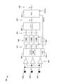
図8は、C-PHY3相インターフェースにおけるレシーバの中に設けられ得るCDR回路のいくつかの態様を示すブロック概略図800を含む。差動レシーバ802a、802b、および802cのセットは、3つ組の中の3本の信号ワイヤ310a、310b、および310cの各々を3つ組の中の3本の信号ワイヤ310a、310b、および310cのうちの他のものと比較することによって、差分信号810のセットを生成するように構成される。図示の例では、第1の差動レシーバ802aが信号ワイヤ310aおよび310bの状態を比較し、第2の差動レシーバ802bが信号ワイヤ310bおよび310cの状態を比較し、第3の差動レシーバ802cが信号ワイヤ310aおよび310cの状態を比較する。したがって、差動レシーバ802a、802b、および802cのうちの少なくとも1つの出力が各シンボル区間の末尾において変化するので、遷移検出回路804は、位相変化の発生を検出するように構成され得る。
FIG. 8 includes a block schematic 800 showing some aspects of a CDR circuit that can be provided within a receiver in a C-PHY 3-phase interface. The set of
送信シンボル間のいくつかの遷移が、単一の差動レシーバ802a、802b、または802cによって検出可能であり得、他の遷移が、差動レシーバ802a、802b、および802cのうちの2つ以上によって検出され得る。一例では、遷移の後、2本のワイヤの状態または相対的な状態が変化しないことがあり、位相遷移の後、対応する差動レシーバ802a、802b、または802cの出力も変化しないことがある。別の例では、信号ワイヤ310a、310b、および/または310cのペアの中の両方のワイヤが第1の時間区間の中で同じ状態にあり得、両方のワイヤが第2の時間区間の中で同じ第2の状態にあり得、位相遷移の後、対応する差動レシーバ802a、802b、または802cが変化しないことがある。したがって、クロック生成回路806は、位相遷移が発生したときを決定するために、すべての差動レシーバ802a、802b、および802cの出力を監視するための遷移検出回路804および/または他の論理を含み得、クロック生成回路は、検出された位相遷移に基づいて受信クロック信号808を生成し得る。
Some transitions between transmit symbols can be detected by a single
3本のワイヤのシグナリング状態の変化は、信号ワイヤ310a、310b、および/または310cの異なる組合せに対して異なる時間において検出され得る。シグナリング状態変化の検出のタイミングは、発生したシグナリング状態変化のタイプに従って変動し得る。そのような変動性の結果が、図8のタイミングチャート850に示される。マーカー822、824、および826は、遷移検出回路804に提供される差分信号810における遷移の発生を表す。マーカー822、824、および826は、単に例示の明快のためにタイミングチャート850において異なる高さが割り当てられ、マーカー822、824、および826の相対的な高さは、クロック生成またはデータ復号のために使用される電圧もしくは電流レベル、極性、または重み付け値の特定の関係を示すことを意図しない。タイミングチャート850は、3本の信号ワイヤ310a、310b、および310c上の位相および極性における、送信されるシンボルに関連する遷移のタイミングの影響を示す。タイミングチャート850において、いくつかのシンボル間の遷移は、シンボルがその間に確実に取り込まれる得る変動する取込みウィンドウ830a、830b、830c、830d、830e、830f、および/または830g(総称して、シンボル取込みウィンドウ830)をもたらすことがある。検出される状態変化の数およびそれらの相対的なタイミングは、クロック信号808上のジッタをもたらし得る。
Changes in the signaling state of the three wires can be detected at different times for different combinations of
C-PHY通信リンクのスループットは、信号遷移時間における持続時間および変動性によって影響を及ぼされることがある。たとえば、検出回路における変動性は、製造プロセス許容差、電圧源および電流源の変動および安定性、ならびに動作温度によって、また信号ワイヤ310a、310b、および310cの電気的特性によって、引き起こされることがある。検出回路における変動性は、チャネル帯域幅を制限することがある。
The throughput of the C-PHY communication link can be affected by the duration and variability in the signal transition time. For example, variability in the detection circuit can be caused by manufacturing process tolerances, voltage and current source variability and stability, and operating temperature, and by the electrical properties of the
図9は、いくつかの連続したシンボル間での第1のシグナリング状態から第2のシグナリング状態への遷移のいくつかの例を表すタイミングチャート900および920を含む。タイミングチャート900および920に示すシグナリング状態遷移は例示のために選択され、MIPIアライアンスC-PHYインターフェースにおいて他の遷移および遷移の組合せが発生することができる。タイミングチャート900および920は、3つ組のワイヤ上での信号レベル間の立上りおよび立下り時間の差異に起因して複数のレシーバ出力遷移が各シンボル区間境界において発生し得る、3ワイヤ3相通信リンクの一例に関する。図8も参照すると、第1のタイミングチャート900は、遷移の前後の3つ組の信号ワイヤ310a、310b、および310c(A、B、およびC)のシグナリング状態を示し、第2のタイミングチャート920は、信号ワイヤ310a、310b、および310cとの間の差異を表す差分信号810を提供する、差動レシーバ802a、802b、および802cの出力を示す。多くの事例では、差動レシーバ802a、802b、および802cのセットは、2本の信号ワイヤ310a、310b、および310cに対する異なる組合せを比較することによって、遷移を取り込むように構成され得る。一例では、これらの差動レシーバ802a、802b、および802cは、それらのそれぞれの入力電圧の差分を(たとえば、減算によって)決定することによって、出力を生成するように構成され得る。
FIG. 9 includes timing charts 900 and 920 showing some examples of the transition from the first signaling state to the second signaling state between several consecutive symbols. The signaling state transitions shown in the timing charts 900 and 920 are selected for illustration purposes and other transition and transition combinations can occur in the MIPI Alliance C-PHY interface. The timing charts 900 and 920 show three-wire, three-phase communication in which multiple receiver output transitions can occur at each symbol section boundary due to differences in rise and fall times between signal levels on a triplet of wires. Regarding an example of a link. Also referring to FIG. 8, the
タイミングチャート900および920に示す例の各々では、初期シンボル(-z)516(図8参照)は異なるシンボルに遷移する。タイミングチャート902、904、および906に示すように、信号Aは最初に+1状態にあり、信号Bは0状態にあり、信号Cは-1状態にある。したがって、差動レシーバ出力に対してタイミングチャート922、932、938に示すように、差動レシーバ802a、802bは、最初に+1差分924を測定し、差動レシーバ802cは-2差分926を測定する。
In each of the examples shown in the timing charts 900 and 920, the initial symbol (-z) 516 (see Figure 8) transitions to a different symbol. As shown in the timing charts 902, 904, and 906, signal A is initially in the +1 state, signal B is in the 0 state, and signal C is in the -1 state. Therefore, as shown in the timing charts 922, 932, 938 for the differential receiver output, the
タイミングチャート902、922に対応する第1の例では、シンボル(-z)516からシンボル(-x)512へ遷移が発生し(図8参照)、ここで、差動レシーバ802aが+1差分924から-2差分930に遷移し、差動レシーバ802bが+1差分924、928のままであり、差動レシーバ802cが-2差分926から+1差分928に遷移して、信号Aは-1状態に遷移し、信号Bは+1状態に遷移し、信号Cは0状態に遷移する。
In the first example corresponding to the timing charts 902 and 922, a transition occurs from symbol (-z) 516 to symbol (-x) 512 (see Figure 8), where the
タイミングチャート904、932に対応する第2の例では、シンボル(-z)516からシンボル(+z)506へ遷移が発生し、ここで、2つの差動レシーバ802aおよび802bが+1差分924から-1差分936に遷移し、差動レシーバ802cが-2差分926から+2差分934に遷移して、信号Aは-1状態に遷移し、信号Bは0状態のままであり、信号Cは+1状態に遷移する。
In the second example corresponding to the timing charts 904, 932, a transition occurs from symbol (-z) 516 to symbol (+ z) 506, where the two
タイミングチャート906、938に対応する第3の例では、シンボル(-z)516からシンボル(+x)502へ遷移が発生し、ここで、差動レシーバ802aが+1差分924から+2差分940に遷移し、差動レシーバ802bが+1差分924から-1差分942に遷移し、差動レシーバ802cが-2差分926から-1差分942に遷移して、信号Aは+1状態のままであり、信号Bは-1状態に遷移し、信号Cは0状態に遷移する。
In the third example corresponding to the timing charts 906 and 938, a transition occurs from symbol (-z) 516 to symbol (+ x) 502, where the
これらの例は、差分値における遷移が0、1、2、3、4、および5レベルに広がることを示す。一般の差動またはシングルエンドのシリアルトランスミッタのために使用されるプリエンファシス技法は、2レベル遷移用に開発されており、MIPIアライアンスC-PHY3相信号上で使用される場合、いくつかの悪影響を持ち込むことがある。詳細には、遷移中に信号を過度に駆動するプリエンファシス回路は、1または2レベルに広がる遷移中にオーバーシュートを引き起こすことがあり、エッジに敏感な回路において誤ったトリガを発生させることがある。 These examples show that transitions in differential values extend to 0, 1, 2, 3, 4, and 5 levels. The pre-emphasis techniques used for common differential or single-ended serial transmitters have been developed for two-level transitions and have some adverse effects when used on the MIPI Alliance C-PHY 3-phase signal. I may bring it in. In particular, pre-emphasis circuits that overdrive the signal during a transition can cause overshoot during a transition that extends to one or two levels, which can cause false triggers in edge-sensitive circuits. ..
図10は、単一のシンボル区間1002を含む複数のシンボル区間の重ね合わせとして生成されるアイパターン1000を示す。信号遷移領域1004は、2つのシンボル間の境界における不確定の時間期間を表し、ここで、変動する信号立上り時間は、信頼できる復号を妨げる。シンボルが安定しており確実に受信および復号され得る時間期間を表す「アイ開口」内のアイマスク1006によって画定される領域において、状態情報が確実に決定され得る。アイマスク1006は、ゼロ交差が発生しない領域をマスクオフし、アイマスクは、最初の信号ゼロ交差に後続するシンボル区間境界における後続のゼロ交差の影響に起因する複数のクロッキングを防止するために、デコーダによって使用される。
FIG. 10 shows an
信号の周期的なサンプリングおよび表示の概念は、受信データの中に現れる頻発する遷移を使用して受信データタイミング信号を再生成するクロックデータ復元回路を使用するシステムの設計、適合、および構成の間に有用である。シリアライザ/デシリアライザ(SERDES)技術に基づく通信システムは、アイパターン1000のアイ開口に基づいてデータを確実に復元する能力を判断するための根拠としてアイパターン1000が利用され得る、システムの一例である。
The concept of periodic sampling and display of a signal is during the design, adaptation, and configuration of a system that uses a clock data recovery circuit to regenerate the received data timing signal using the frequent transitions that appear in the received data. It is useful for. A communication system based on serializer / deserializer (SERDES) technology is an example of a system in which the
3ワイヤ3相エンコーダなどのMワイヤN相符号化システムは、すべてのシンボル境界において少なくとも1つの遷移を有する信号を符号化し得、レシーバは、それらの保証された遷移を使用してクロックを復元し得る。レシーバは、シンボル境界における最初の信号遷移の直前に、信頼できるデータを必要とし得、また同じシンボル境界と相互に関連する複数の遷移のいかなる発生も確実にマスキングすることが可能でなければならない。Mワイヤ(たとえば、3つ組のワイヤ)上で搬送される信号の間の立上りおよび立下り時間のわずかな差異に起因して、かつ受信された信号ペアの組合せ(たとえば、図6の差動レシーバ802a、802b、および802cのA-B、B-C、およびC-A出力)の間の信号伝搬時間のわずかな差異に起因して、複数のレシーバ遷移が発生し得る。
M-wire N-phase coding systems, such as 3-wire 3-phase encoders, can encode signals with at least one transition at all symbol boundaries, and the receiver restores the clock using those guaranteed transitions. obtain. The receiver may need reliable data just prior to the first signal transition at the symbol boundary and must be able to reliably mask any occurrence of multiple transitions interrelated to the same symbol boundary. The combination of signal pairs received (eg, differential in Figure 6) due to slight differences in rise and fall times between signals carried over M-wires (eg, triple wires). Multiple receiver transitions can occur due to slight differences in signal propagation time between
図11は、C-PHY3相信号に対して生成されるアイパターン1100の一例を示す。アイパターン1100は、複数のシンボル区間1102の重ね合わせから生成され得る。アイパターン1100は、固定された、かつ/またはシンボルから独立した、トリガ1130を使用して作成され得る。アイパターン1100は、差動レシーバ802a、802b、802c、およびN相レシーバ回路(図8参照)によって測定される複数の電圧レベルによるものと考えられ得る、増大した数の電圧レベル1120、1122、1124、1126、1128を含む。この例では、アイパターン1100は、差動レシーバ802a、802b、および802cに提供される3ワイヤ3相符号化信号における可能な遷移に対応し得る。3つの電圧レベルは、差動レシーバ802a、802b、および802cに、正極性と負極性の両方に対する強電圧レベル1126、1128、および弱電圧レベル1122、1124を生成させ得る。通常、1本の信号ワイヤ310a、310b、および310cだけが任意のシンボルの中で非駆動であり、差動レシーバ802a、802b、および802cは、出力として0状態(ここでは0ボルト)を生成しない。強レベルおよび弱レベルに関連する電圧は、0ボルトレベルに対して均等に離間される必要はない。たとえば、弱電圧レベル1122、1124は、非駆動信号ワイヤ310a、310bおよび310cが達する電圧レベルを含み得る電圧の比較を表す。受信デバイスにおいてデータが取り込まれるときに信号の3つのペアのすべてが同時であるものと見なされるので、アイパターン1100は、差動レシーバ802a、802b、および802cによって生成される波形を重複させてよい。差動レシーバ802a、802b、および802cによって生成される波形は、信号の3つのペア(A-B、B-C、およびC-A)の比較を表す差分信号810を表す。
FIG. 11 shows an example of the
C-PHY3相デコーダにおいて使用されるドライバ、レシーバ、および他のデバイスは、3本のワイヤから受信された信号間に相対的な遅延を持ち込むことがある異なるスイッチング特性を示し得る。3つ組の信号ワイヤ310a、310b、310cの3本の信号の間の立上りおよび立下り時間のわずかな差異に起因して、かつ信号ワイヤ310a、310b、310cから受信された信号のペアの組合せの間の信号伝搬時間のわずかな差異に起因して、各シンボル区間境界1108および/または1114において複数のレシーバ出力遷移が観測され得る。アイパターン1100は、立上りおよび立下り時間における変動を、各シンボル区間境界1108および1114の近くの遷移における相対的な遅延として取り込み得る。立上りおよび立下り時間における変動は、3相ドライバの異なる特性に起因し得る。立上りおよび立下り時間の差異も、任意の所与のシンボルにとってのシンボル区間1102の持続時間を実効的に短くまたは長くする結果となり得る。
Drivers, receivers, and other devices used in C-PHY 3-phase decoders can exhibit different switching characteristics that can introduce relative delays between the signals received from the three wires. A combination of pairs of signals received from
信号遷移領域1104は、不確定の時間または期間を表し、ここで、変動する信号立上り時間は、信頼できる復号を妨げる。シンボルが安定しており確実に受信および復号され得る時間期間を表す「アイ開口」1106の中で、状態情報が確実に決定され得る。一例では、アイ開口1106は、信号遷移領域1104の末尾1112において開始するとともに、シンボル区間1102のシンボル区間境界1114において終わるように決定され得る。図11に示す例では、アイ開口1106は、信号遷移領域1104の末尾1112において開始するとともに、信号ワイヤ310a、310b、310cのシグナリング状態ならびに/または3つの差動レシーバ802a、802b、および802cの出力が次のシンボルを反映するように変化し始めた時間1116において終わるように決定され得る。
The
N相符号化のために構成された通信リンク220の最大速度は、受信信号に対応するアイ開口1106と比較した信号遷移領域1104の持続時間によって制限され得る。シンボル区間1102にとっての最小期間は、たとえば、図6に示すデコーダ600の中のCDR回路624に関連する厳しい設計マージンによって制約され得る。異なるシグナリング状態遷移は、2本以上の信号ワイヤ310a、310b、および/または310cに対応する信号遷移時間における異なる変動に関連し得、それによって、受信デバイスの中の差動レシーバ802a、802b、および802cの出力を、差動レシーバ802a、802b、および802cの入力が変化し始めるシンボル区間境界1108に対して異なる時間および/またはレートにおいて変化させる。信号遷移時間の間の差は、2つ以上の差分信号810におけるシグナリング遷移間のタイミングスキューをもたらすことがある。CDR回路は、差分信号810の間のタイミングスキューに対応するための遅延要素および他の回路を含み得る。
The maximum speed of the
図12は、3ワイヤ3相インターフェース用のCDR回路1200の一例を提供する。図示したCDR回路1200は、多くの異なるタイプのクロック復元回路にとって共通であるいくつかの機能および機能要素を含む。CDR回路1200は、たとえば、図8の差動レシーバ802a、802b、および802cによって生成された差分信号810から導出され得る差分信号1202、1204、1206を受信する。CDR回路1200において、各差分信号1202、1204、1206は、Dフリップフロップのペア1210a、1210b、1210cをクロッキングして出力信号1230a~1230fを生成する。出力信号1230a~1230fは、対応する差分信号1202、1204、1206の上で遷移が検出されるとパルスを搬送する。Dフリップフロップにおけるクロック入力に供給される立上りエッジは、Dフリップフロップを通じて論理1をクロッキングする。インバータ1208a、1208b、1208cは、対応するDフリップフロップの各ペア1210a、1210b、1210cにおけるDフリップフロップのうちの一方に、差分信号1202、1204、1206の反転バージョンを提供するために使用され得る。したがって、Dフリップフロップの各ペア1210a、1210b、1210cは、対応する差分信号1202、1204、1206において検出された立上りエッジおよび立下りエッジに応答してパルスを生成する。
FIG. 12 provides an example of a
たとえば、AB差分信号1202が、Dフリップフロップの第1のペア1210aの第1のDフリップフロップ1232に提供され、インバータ1208aは、AB差分信号1202の反転バージョンをDフリップフロップの第1のペア1210aの第2のDフリップフロップ1234に提供する。Dフリップフロップは、当初はリセット状態にある。AB差分信号1202における立上りエッジが、第1のDフリップフロップ1232を通じて論理1をクロッキングして、第1のフリップフロップの出力(r_AB)1230aを論理1状態に遷移させる。AB差分信号1202における立下りエッジが、第2のDフリップフロップ1234を通じて論理1をクロッキングして、第2のフリップフロップの出力(f_AB)1230bを論理1状態に遷移させる。
For example, an
出力信号1230a~1230fは、ORゲート1212などの論理に提供され、そうした論理は、レシーバクロック(RxCLK)信号1222として働き得る出力信号を生成する。差分信号1202、1204、1206のうちのいずれかのシグナリング状態において遷移が発生するとき、RxCLK信号1222が論理1状態に遷移する。RxCLK信号1222は、プログラマブル遅延要素1214に供給され、プログラマブル遅延要素1214は、Dフリップフロップのペア1210a、1210b、1210cにおけるDフリップフロップをリセットするリセット信号(rb)1228を駆動する。図示の例では、Dフリップフロップがロー信号によってリセットされるとき、インバータ1216が含まれ得る。Dフリップフロップがリセットされると、ORゲート1212の出力が論理0状態に戻り、RxCLK信号1222上のパルスは終了する。この論理0状態がプログラマブル遅延要素1214およびインバータ1216を通って伝搬すると、Dフリップフロップにおけるリセット条件が解放される。Dフリップフロップがリセット条件にある間、差分信号1202、1204、1206における遷移は無視される。
The output signals 1230a-1230f are provided for logic such as the
プログラマブル遅延要素1214は、通常、差分信号1202、1204、1206における最初および最後の遷移の発生の間のタイミングスキューの差を上回る持続時間を有する遅延を生成するように構成される。プログラマブル遅延要素1214は、RxCLK信号1222上でのパルスの持続時間(すなわち、パルス幅)を構成する。プログラマブル遅延要素1214は、プロセッサまたは他の制御論理および/もしくは構成論理によってSet信号1226がアサートされると構成され得る。
The
RxCLK信号1222はまた、差分信号1202、1204、1206のシグナリング状態を取り込む3つのフリップフロップ1220のセットに供給されてよく、RxCLK信号1222上で発生する各パルスに対して安定な出力シンボル1224を提供する。遅延または整合論理1218が、差分信号1202、1204、1206のセットのタイミングを調整し得る。たとえば、遅延または整合論理1218は、差分信号1202、1204、1206が安定しているときにフリップフロップ1220が差分信号1202、1204、1206のシグナリング状態を取り込むことを確実にするように、RxCLK信号1222上のパルスに対する差分信号1202、1204、1206のタイミングを調整するために使用され得る。遅延または整合論理1218は、プログラマブル遅延要素1214に対して構成された遅延に基づいて、差分信号1202、1204、1206におけるエッジを遅延させ得る。
The
プログラマブル遅延要素1214は、差分信号1202、1204、1206における遷移時間の可能な大きい変動に対応するためにCDR回路1200の中に構成され得る。一例では、プログラマブル遅延要素1214は、差分信号1202、1204、1206における最初および最後の遷移の発生の間のタイミングスキューの持続時間を上回る最小遅延期間を導入し得る。CDR回路1200の信頼できる動作のために、プログラマブル遅延要素1214によって与えられる最大遅延時間は、シンボル区間以下であってよい。もっと高速なデータレートにおいて、タイミングスキューはシンボル区間1102の部分として増大し、アイ開口1106はシンボル区間1102と比較して小さくなることがある。タイミングスキューが、アイ開口1106によって占有されるシンボル区間1102のパーセンテージを、シンボルの信頼できる取込みをサポートできるしきい値サイズよりも小さく低減するとき、最大シンボル送信レートが制限されることがある。
The
図13は、CDR回路1200の動作のいくつかの態様を示すタイミング図である。図は、プログラマブル遅延要素1214が構成された後の動作に関し、Set信号1226はアクティブでない。CDR回路1200は、エッジ検出器として動作する。C-PHY3相符号化は、単位区間(UI)1302ごとに単一のシグナリング状態遷移をもたらす。3つ組の各ワイヤの状態の差および/または3つ組の送信特性は、異なる時間において2つ以上のワイヤ上に遷移を出現させ得る。差分信号1202、1204、1206における遷移の発生の時間的な最大差分は、スキュー時間(tskew)1304と呼ばれることがある。CDR回路1200に関連する他の遅延は、Dフリップフロップのペア1210a、1210b、1210cを通じた伝搬遅延(tck2q)1314、ORゲート1212を通過した立上りエッジに関連する伝搬遅延(tOR_0)1316、ORゲート1212を通過した立下りエッジに関連する伝搬遅延(tOR_1)1318、プログラマブル遅延要素1214およびドライバ/インバータ1216によって導入される遅延を組み合わせるプログラマブル遅延(tpgm)1310、ならびにDフリップフロップのペア1210a、1210b、1210cによるrb信号1228の受信の時間とフリップフロップ出力がクリアされる時間との間の遅延に対応するリセット遅延(trst)1312を含む。
FIG. 13 is a timing diagram showing some aspects of the operation of the
ループ時間(tloop)1320は以下のように定義され得る。
tloop=tck2q+tOR_1+tpgm+trst+tOR_0+tpgm
tloop1320とUI1302との間の関係が、CDR回路1200の動作の信頼性を決定し得る。この関係は、送信用に使用されUI1302に対して直接の影響を有するクロック周波数、およびプログラマブル遅延要素1214の動作の変動性によって影響を及ぼされる。
The loop time (t loop ) 1320 can be defined as:
t loop = t ck2q + t OR_1 + t pgm + t rst + t OR_0 + t pgm
The relationship between
いくつかのデバイスでは、プログラマブル遅延要素1214の動作は、製造プロセスにおけるばらつき、回路電源電圧、およびダイ温度(PVT)によって影響を及ぼされることがある。構成された値に対してプログラマブル遅延要素1214によって与えられる遅延時間は、デバイス間および/またはデバイス内の回路間で著しく変動し得る。従来のシステムでは、CDR回路1200の公称動作条件は、概して、最悪のケースのPVT影響下でさえ、信号遷移領域1104の末尾1112の後かつ次のシンボルへの遷移領域の始まりの前にクロックエッジが発生することを確実にするために、すべてのPVT条件下でアイ開口1106の中間におけるどこかでクロックエッジを生成するための設計によって設定される。送信周波数が高くなり、差分信号1202、1204、1206のタイミングスキューがUI1302と比較して大きいとき、アイ開口1106内のクロックエッジを保証するCDR回路1200を設計する際に難題が生じ得る。たとえば、一般の遅延要素は、すべてのPVT条件にわたって2倍に変化する遅延値を生成し得る。
In some devices, the operation of the
図14は、不十分な遅延しか与えないプログラマブル遅延要素1214の影響を示すタイミング図1400である。この例では、tloop1406は、観測されるtskew1404にとって短すぎ、1つのUI1402の中で複数のクロックパルス1408、1410が生成される。すなわち、ループ遅延tloop1406はtskew1404に比べて十分に大きくなく、差分信号1202、1204、1206において後で発生する遷移はマスキングされない。図示の例では、差分信号1206のうちの1つにおける第2の遷移1414は、差分信号1202のうちの別のものにおいて最初に発生する遷移1412に応答してパルス1408が生成された後、検出され得る。この例では、復元されるクロック周波数は、3相インターフェース上でシンボルを送信するために使用されるクロック周波数の2倍であり得る。
FIG. 14 is a timing diagram 1400 showing the effect of the
図15は、長すぎる遅延を与えるプログラマブル遅延要素1214の影響を示すタイミング図1500である。この例では、tloop1506はUI1502よりも大きい。CDR回路1200は、第1のUI1502の中で最初に発生する遷移1514に応答してクロックパルス1508を生成し得るが、遷移1516、1518が2番目のUI1512の中で発生するとき、rb信号1228はアクティブであり得る。図示の例では、2番目のUI1512の中の遷移1516、1518はマスキングされ、2番目のUI1512に対応する予想パルス1510が抑制される。この例では、復元されるクロック周波数は、3相インターフェース上でシンボルを送信するために使用されるクロック周波数の半分であり得る。
FIG. 15 is a timing diagram 1500 showing the effect of the
図14および図15の例によって示すように、CDR回路1200は、以下の制約を受けてよい。
tskew<tloop<UI
実証的経験は、tloop1320、1406、1506がPVTに極めて敏感であることを示唆する。いくつかの事例では、プログラマブル遅延要素1214によって与えられる遅延は、PVTの潜在的な変動の範囲に対応するように増大されてよい。データレートが増大し、UIの持続時間が減少し、tskewがUIに対して比例して増大するとき、プログラマブル遅延要素1214を構成するために利用可能な遅延の潜在的な範囲が低減する。
As shown by the examples of FIGS. 14 and 15, the
t skew <t loop <UI
Empirical experience suggests that
C-PHY3相インターフェース用のクロック較正
本明細書で開示するいくつかの態様は、C-PHY多相レシーバの中で使用されるクロック復元回路の較正に関する。クロック復元回路は、PVTの変動に関連する問題に対応するように較正され得る。いくつかの態様によれば、C-PHY3相レシーバの中のクロック復元回路は、UI1302(図13参照)に基づいて較正され得る。UI1302は、シンボル送信区間またはシンボル区間と呼ばれることもあり、レシーバにおいて変動するPVT条件にわたって一定のままであると想定され得るシステム規定されたパラメータである。
Clock Calibration for the C-PHY 3-Phase Interface Some aspects disclosed herein relate to the calibration of the clock recovery circuit used in the C-PHY polyphase receiver. The clock recovery circuit can be calibrated to address the problems associated with PVT fluctuations. According to some embodiments, the clock recovery circuit in the C-PHY 3-phase receiver can be calibrated based on UI1302 (see Figure 13). UI1302, sometimes referred to as the symbol transmission interval or symbol interval, is a system-defined parameter that can be expected to remain constant over variable PVT conditions at the receiver.
いくつかの態様によれば、ループ時間tloopとUI1302の持続時間との間の差が最小化されるとき、クロック復元回路が較正され得る。tloopがまったくUI1302の持続時間を上回らないとき、クロックパルスは逸失されない。tloopの持続時間がUI1302に近いとき、UI1302の中の複数パルスの最大限の抑制が得られる。本明細書で開示するいくつかの態様は、tloop<UIという制約を満たしながら最大限のジッタマスキングをもたらすtloop持続時間を取得するように、クロック復元回路を構成するために使用され得る較正プロセスに関する。 According to some embodiments, the clock recovery circuit can be calibrated when the difference between the loop time t loop and the duration of UI1302 is minimized. The clock pulse is not lost when the t loop does not exceed the duration of UI1302 at all. When the duration of the t loop is close to UI1302, maximum suppression of multiple pulses in UI1302 is obtained. Some embodiments disclosed herein are calibrations that can be used to configure the clock recovery circuit to obtain a t loop duration that results in maximum jitter masking while satisfying the t loop <UI constraint. Regarding the process.
図16は、本明細書で開示するいくつかの態様に従って較正されたC-PHY3相レシーバの中のクロック復元回路の動作を示すタイミング図1600である。図示の例では、tloop持続時間1604はUI1602よりも短く、tloop持続時間1604はtskew1612よりも長い。tloop持続時間1604とUI1602との間の差(UI-tloop)1606が最小化されてよく、図12のCDR回路1200の障害の潜在的なモードは、たとえば、1つまたは複数のプログラマブル遅延要素を構成するための較正プロセスの使用を通じて回避され得る。
FIG. 16 is a timing diagram 1600 showing the operation of a clock recovery circuit in a C-PHY 3-phase receiver calibrated according to some aspects disclosed herein. In the illustrated example, the t loop duration 1604 is shorter than the UI1602 and the t loop duration 1604 is longer than the
較正は、tloop持続時間1604に作用する1つまたは複数の遅延要素を調整しながら、クロック復元回路によって生成される受信クロックの周波数を観測することを含み得る。図12におけるCDR回路1200の例では、tloop持続時間1604を調整するためにプログラマブル遅延1214が使用され得る。プログラマブル遅延1214は、CDR回路1200の障害の潜在的な2つのモードを示す図14および図15のタイミング図に示すように、RxCLK信号1222の周波数に作用し得る。たとえば、CDR回路1200の障害の第1のモードは、tloop>UIであるときに発生し、その結果、CDR回路1200によって復元されるRxCLK信号1222は、C-PHYインターフェースの公称シンボル送信周波数の半分である周波数を有する。CDR回路1200の障害の第2のモードは、tloop<tskewであるときに発生し、ここで、tskewは、CDR回路1200によって復元されるRxCLK信号1222がC-PHYインターフェースの公称シンボル送信周波数であり得る周波数を有するときのジッタ(図11の遷移領域1104を参照)の期間を表す。
Calibration may include observing the frequency of the received clock produced by the clock recovery circuit while adjusting for one or more delay factors acting on the t loop duration 1604. In the example of the
CDR回路1200は、RxCLK信号1222の周波数が変化するまでプログラマブル遅延要素1214を徐々に修正することによって較正され得る。周波数が半分または2倍になる変化は、CDR回路1200にとって安定な動作条件を示し得る。較正は、プログラマブル遅延要素1214に対して小さい値とともに、またはプログラマブル遅延要素1214に対して大きい値とともに、開始してよい。遅延値は、次いで、1つまたは複数の周波数変化が起こるまで徐々に変更される。通常動作において使用される遅延値は、RxCLK信号1222の周波数を2倍または半分にする前の、最後の値に基づいて決定されてよい。いくつかの事例では、遅延値は、RxCLK信号1222の周波数が半分になるまで増大されてよく、次いで、遅延値は、RxCLK信号1222の周波数がその前の値に戻るまで徐々に減少される。他の事例では、遅延値は、RxCLK信号1222の周波数が2倍になるまで減少されてよく、次いで、遅延値は、RxCLK信号1222の周波数がその前の値に戻るまで徐々に増大される。
The
一例では、プログラマブル遅延1214は、C-PHYインターフェースの公称シンボル送信周波数に一致する周波数をRxCLK信号1222が有するように初期化されてよい。プログラマブル遅延1214は、RxCLK信号1222の周波数が減少して、1つまたは複数の遷移に対してパルス生成が抑制されたことを示すまで、tloop持続時間1604を増大させるように調整されてよい。プログラマブル遅延1214は、C-PHYインターフェースの公称シンボル送信周波数に一致する周波数を有するRxCLK信号1222をもたらすtloop持続時間1604を与えるように、観測された最大値に設定されてよい。いくつかの事例では、プログラマブル遅延1214の値は、RxCLK信号1222の周波数がC-PHYインターフェースの送信周波数に一致するまで段階的に減少されてよい。
In one example, the
別の例では、プログラマブル遅延1214は、C-PHYインターフェースの公称シンボル送信周波数よりも低い周波数をRxCLK信号1222が有するように初期化されてよい。プログラマブル遅延1214は、次いで、RxCLK信号1222の周波数がC-PHYインターフェースの送信周波数に一致するまで、tloop持続時間1604を減少させるように調整されてよい。
In another example, the
いくつかの態様によれば、レシーバは、C-PHYインターフェースの公称シンボル送信周波数を事前に知っている必要がなく、トレーニングシーケンスが正確に受信されると、較正が達成されたと決定してよい。トランスミッタは、リンク初期化中、データの個々のパケットを送信する前、レシーバにおけるエラーの検出の後、かつ/あるいはアプリケーションまたはシステムの制御下で、トレーニングシーケンスを送ってよい。レシーバは、C-PHYインターフェースのアクティビティを監視してよく、遷移を検出すると較正を実行してよい。いくつかの事例では、トレーニングシーケンスが適切に受信されない場合、レシーバは、CDR回路1200がすでに較正されていると決定してよく、較正を実行してよい。
According to some embodiments, the receiver does not need to know in advance the nominal symbol transmission frequency of the C-PHY interface and may determine that calibration has been achieved when the training sequence is received accurately. The transmitter may send a training sequence during link initialization, before sending individual packets of data, after detecting an error at the receiver, and / or under the control of the application or system. The receiver may monitor the activity of the C-PHY interface and perform calibration when it detects a transition. In some cases, if the training sequence is not properly received, the receiver may determine that the
一例では、CDR回路1200がトレーニングシーケンスを検出することを可能にする所定の値にプログラマブル遅延1214が初期化されると、較正が開始する。プログラマブル遅延1214は、次いで、トレーニングシーケンスの中でエラーが検出されるまで、tloop持続時間1604を増大させるように調整されてよい。CDR回路1200は通常動作用に構成されてよく、プログラマブル遅延1214は、トレーニングシーケンスの中でエラーを検出させる値よりも小さい1つまたは複数の増分である値を有する。
In one example, calibration begins when the
別の例では、CDR回路1200がエラーなしにトレーニングシーケンスを受信することを妨害する所定の値にプログラマブル遅延1214が初期化されると、較正が開始する。プログラマブル遅延1214は、次いで、トレーニングシーケンスがCDR回路1200によって受信されるときに一貫してエラーがなくなるまで、tloop持続時間1604を増大または減少させるように調整されてよい。
In another example, calibration begins when the
図17は、本明細書で開示するいくつかの態様に従って較正され得るクロック復元回路1700を示す。クロック復元回路1700は、タイミング制約tskew<tloop<UIのときに3相インターフェース上で送信されたシンボルを確実に取り込むために使用され得る第1のクロック信号(rclk信号1712)を供給し得る。クロック復元回路1700は、rclkクロック信号1712、および入力1710からクロック情報を復元するために使用され得る第2のクロック信号(ref_clk信号1714)を生成するように構成される2つのCDR回路1702、1704を含み、入力1710は、差分信号1202、1204、1206、および差分信号1202、1204、1206の反転バージョンを含み得る。ref_clkクロック信号1714は、Frefの周波数を有する基準クロックとして使用され得る。rclkクロック信号1712は、ref_clk信号1714の周波数の倍数である周波数(すなわち、2Fref、1Fref、0.5Fref、0.25×Frefなど)を有してよい。第1のCDR回路1702および第2のCDR回路1704は、類似のアーキテクチャを有してよい。
FIG. 17 shows a
ref_clk信号1714の周波数に対するrclk信号1712の周波数を検出し、rclk信号1712の周波数とref_clk信号1714の周波数との間の所望の関係まで、第1のCDR回路1702の中の1つまたは複数のプログラマブル遅延要素の値を調整するために、CDR較正論理1706が設けられ得る。一例では、CDR較正論理1706は、第1のCDR回路1702の中のプログラマブル遅延要素によって生成される遅延の持続時間を構成するマルチビット制御信号1716を提供し得る。較正の1つのモードでは、プログラマブル遅延の値は、UI1618、1620のいくつかの部分に対するパルス生成の抑制が得られるまで調整され得る。較正の別のモードでは、プログラマブル遅延の値は、複数のクロックパルスがいくつかのUI1618、1620の中で生成されるまで調整され得る。
Detects the frequency of the
プログラマブル遅延要素は、rclkクロック信号1712の周波数を監視しながら、プログラムされる遅延を調整することによって構成され得る。最初に、プログラムされる遅延は、UI時間(1シンボルを送信するのに必要とされる時間)よりも小さい値に最初に設定されてよい。したがって、3相信号が最初に受信されると、クロック復元回路は、シンボル送信周波数に等しい周波数を有するrclkクロック信号1712を生成するように構成され得る。プログラムされる遅延の値は、次いで、rclkクロック信号1712の周波数が2によって、3によって、または任意の所望のファクタによって除算されるまで、徐々に増大される。
The programmable delay element can be configured by adjusting the programmed delay while monitoring the frequency of the
図18は、第1のCDR回路1702の遅延要素を構成するために使用され得るCDR較正回路1800の一例を示す。CDR較正回路1800は、処理回路によって提供され得る信号1812によってイネーブルされ得る。CDR較正回路1800は、ref_clk信号1714および較正クロック(cal_clk)信号1814を駆動し、かつ/またはそれらのタイミングを調整するために使用される調整論理1802を含み得る。一例では、ref_clk信号1714は、基準CDR回路(たとえば、第2のCDR回路1704)、自励発振器、位相ロックループ、または他のクロック生成回路から導出され得る。CDR較正回路1800は、ref_clk信号1714およびcal_clk信号1814の調整済みバージョンによってクロッキングされるカウンタ1804および1806を含み得る。カウンタ1804および1806の出力が、比較器論理1808によって監視され得、比較器論理1808は、cal_clk信号1814に対するref_clk信号1714の周波数を決定し得る。較正カウンタ1810は、CDR回路(たとえば、第1のCDR回路1702)の中の1つまたは複数のプログラマブル遅延要素を制御するように、連続する較正サイクル中に調整され得る。較正カウンタ1810は、たとえば、比較器論理1808によって行われた決定に応じて、各較正サイクル後、インクリメントまたはデクリメントされ得る。比較器論理1808は、アップ/ダウン信号1820、イネーブルカウンタ信号1822、および較正サイクルクロック信号1824のうちの1つまたは複数を使用して、較正カウンタ1810を制御し得る。
FIG. 18 shows an example of a
クロック周波数は、カウンタ1804、1806を使用して測定され得る。カウンタ1804、1806は、たとえば、較正サイクルクロック信号1824によって決定され得る所定の時間期間にわたって、ref_clk信号1714およびcal_clk信号1814によってインクリメントされ得る。第1のカウンタ1804は、ref_clk信号1714に対応するクロックサイクルの数(ref_val)1816を取り込み得る。いくつかの事例では、第1のカウンタは、フルレートシンボル送信クロックの測定値であるref_val1816を取り込むために初期化の直後に動作させられてよく、いくつかの事例では、最初に取得されるこのref_val1816は、後続の較正サイクルのために使用されるように記録されてよく、または別のやり方で取り込まれてよい。第2のカウンタ1806は、較正サイクル中に発生するクロックサイクルの数(cal_val)1818をカウントする。較正サイクルは、所定の時間期間として構成されてよく、または調整可能な時間期間であってよい。較正サイクルごとに、制御信号1716は、較正下にあるCDR回路1702に遅延パラメータを提供し、得られたcal_clk信号1814の周波数は、較正サイクル中に第2のカウンタ1806によって累積されたcal_val1818として測定され得る。cal_val1818が所望のファクタによるクロック周波数の除算である値を反映するとき、構成が完了しており、遅延パラメータの対応する値が、クロック復元回路を動作させるために使用され得る。
The clock frequency can be measured using
図19は、本明細書で開示する1つまたは複数の機能を実行するように構成され得る処理回路1902を採用する装置のためのハードウェア実装形態の一例を示す概念図1900である。本開示の様々な態様によれば、本明細書で開示するような要素、または要素の任意の部分、または要素の任意の組合せは、処理回路1902を使用して実装され得る。処理回路1902は、ハードウェアモジュールとソフトウェアモジュールとのいくつかの組合せによって制御される1つまたは複数のプロセッサ1904を含み得る。プロセッサ1904の例は、マイクロプロセッサ、マイクロコントローラ、デジタル信号プロセッサ(DSP)、フィールドプログラマブルゲートアレイ(FPGA)、プログラマブル論理デバイス(PLD)、ステートマシン、シーケンサ、ゲート論理、個別ハードウェア回路、および本開示全体にわたって説明する様々な機能を実行するように構成された他の適切なハードウェアを含む。1つまたは複数のプロセッサ1904は、特定の機能を実行するとともに、ソフトウェアモジュール1916のうちの1つによって構成、増強、または制御され得る専用プロセッサを含み得る。1つまたは複数のプロセッサ1904は、初期化中にロードされたソフトウェアモジュール1916の組合せを介して構成されてよく、動作中に1つまたは複数のソフトウェアモジュール1916をロードまたはアンロードすることによってさらに構成されてよい。
FIG. 19 is a conceptual diagram 1900 showing an example of a hardware implementation for an apparatus that employs a
図示の例では、処理回路1902は、バス1910によって概略的に表されるバスアーキテクチャを用いて実装され得る。バス1910は、処理回路1902の特定の適用例および全体的な設計制約に応じて、任意の数の相互接続バスおよびブリッジを含み得る。バス1910は、1つまたは複数のプロセッサ1904およびストレージ1906を含む様々な回路を互いにリンクさせる。ストレージ1906は、メモリデバイスおよび大容量記憶デバイスを含んでよく、本明細書ではコンピュータ可読媒体および/またはプロセッサ可読媒体と呼ばれることがある。バス1910はまた、タイミングソース、タイマー、周辺装置、電圧調整器、および電力管理回路などの様々な他の回路をリンクさせ得る。バスインターフェース1908は、バス1910と1つまたは複数のトランシーバ1912との間のインターフェースを提供し得る。トランシーバ1912は、処理回路によってサポートされるネットワーキング技術ごとに設けられてよい。いくつかの事例では、複数のネットワーキング技術が、トランシーバ1912の中に見られる回路構成または処理モジュールの一部または全部を共有し得る。各トランシーバ1912は、伝送媒体を介して様々な他の装置と通信するための手段を提供する。装置の性質に応じて、ユーザインターフェース1918(たとえば、キーパッド、ディスプレイ、スピーカー、マイクロフォン、ジョイスティック)も設けられてよく、直接またはバスインターフェース1908を通じてバス1910に通信可能に結合されてよい。
In the illustrated example, the
プロセッサ1904は、バス1910を管理すること、およびストレージ1906を含み得るコンピュータ可読媒体に記憶されたソフトウェアの実行を含み得る一般的な処理を担当し得る。この点において、プロセッサ1904を含む処理回路1902は、本明細書で開示する方法、機能、および技法のいずれかを実施するために使用され得る。ストレージ1906は、ソフトウェアを実行するとき、プロセッサ1904によって操作されるデータを記憶するために使用され得、ソフトウェアは、本明細書で開示する方法のうちの任意の1つを実施するように構成され得る。
処理回路1902の中の1つまたは複数のプロセッサ1904は、ソフトウェアを実行し得る。ソフトウェアは、ソフトウェア、ファームウェア、ミドルウェア、マイクロコード、ハードウェア記述言語と呼ばれるか、または他の名称で呼ばれるかどうかにかかわらず、命令、命令セット、コード、コードセグメント、プログラムコード、プログラム、サブプログラム、ソフトウェアモジュール、アプリケーション、ソフトウェアアプリケーション、ソフトウェアパッケージ、ルーチン、サブルーチン、オブジェクト、実行ファイル、実行スレッド、プロシージャ、関数、アルゴリズムなどを意味するように広く解釈されなければならない。ソフトウェアは、コンピュータ可読形式でストレージ1906の中または外部コンピュータ可読媒体の中に存在してよい。外部コンピュータ可読媒体および/またはストレージ1906は、非一時的コンピュータ可読媒体を含み得る。非一時的コンピュータ可読媒体は、例として、磁気記憶デバイス(たとえば、ハードディスク、フロッピーディスク、磁気ストリップ)、光ディスク(たとえば、コンパクトディスク(CD)またはデジタル多用途ディスク(DVD))、スマートカード、フラッシュメモリデバイス(たとえば、「フラッシュドライブ」、カード、スティック、またはキードライブ)、ランダムアクセスメモリ(RAM)、ROM、PROM、消去可能PROM(EPROM)、EEPROM、レジスタ、リムーバブルディスク、ならびにコンピュータによってアクセスされ得るとともに読み取られ得るソフトウェアおよび/または命令を記憶するための任意の他の適切な媒体を含む。コンピュータ可読媒体および/またはストレージ1906はまた、例として、搬送波、伝送線路、ならびにコンピュータによってアクセスされ得るとともに読み取られ得るソフトウェアおよび/または命令を送信するための任意の他の適切な媒体を含み得る。コンピュータ可読媒体および/またはストレージ1906は、処理回路1902の中、プロセッサ1904の中、処理回路1902の外部に存在してよく、または処理回路1902を含む複数のエンティティにわたって分散されてもよい。コンピュータ可読媒体および/またはストレージ1906は、コンピュータプログラム製品に組み込まれてよい。例として、コンピュータプログラム製品は、パッケージング材料の中にコンピュータ可読媒体を含めることがある。特定の適用例およびシステム全体に課される全体的な設計制約に応じて、本開示全体にわたって提示された説明した機能を実施するための最善の方法を、当業者は認識されよう。
One or
ストレージ1906は、本明細書ではソフトウェアモジュール1916と呼ばれることがある、ロード可能なコードセグメント、モジュール、アプリケーション、プログラムなどで保持および/または編成されたソフトウェアを保持し得る。ソフトウェアモジュール1916の各々は、処理回路1902にインストールまたはロードされるとともに1つまたは複数のプロセッサ1904によって実行されたとき、1つまたは複数のプロセッサ1904の動作を制御するランタイムイメージ1914に寄与する命令およびデータを含み得る。実行されたとき、いくつかの命令は、処理回路1902に、本明細書で説明するいくつかの方法、アルゴリズム、およびプロセスに従って機能を実施させ得る。
ソフトウェアモジュール1916のうちのいくつかは、処理回路1902の初期化中にロードされてよく、これらのソフトウェアモジュール1916は、本明細書で開示する様々な機能の実行を可能にするように処理回路1902を構成してよい。たとえば、いくつかのソフトウェアモジュール1916は、プロセッサ1904の内部デバイスおよび/または論理回路1922を構成し得、トランシーバ1912、バスインターフェース1908、ユーザインターフェース1918、タイマー、数理コプロセッサなどの外部デバイスへのアクセスを管理し得る。ソフトウェアモジュール1916は、割込みハンドラおよびデバイスドライバと対話するとともに処理回路1902によって提供される様々なリソースへのアクセスを制御する、制御プログラムおよび/またはオペレーティングシステムを含み得る。リソースは、メモリ、処理時間、トランシーバ1912へのアクセス、ユーザインターフェース1918などを含み得る。
Some of the
処理回路1902の1つまたは複数のプロセッサ1904は、多機能であってよく、それによって、ソフトウェアモジュール1916のうちのいくつかがロードされ、異なる機能または同じ機能の異なるインスタンスを実行するように構成される。1つまたは複数のプロセッサ1904は、追加として、たとえば、ユーザインターフェース1918、トランシーバ1912、およびデバイスドライバからの入力に応答して開始されるバックグラウンドタスクを管理するように適合され得る。複数の機能の実行をサポートするために、1つまたは複数のプロセッサ1904は、マルチタスク環境を提供するように構成されてよく、それによって、複数の機能の各々が、必要または要望に応じて、1つまたは複数のプロセッサ1904によってサービスされるタスクのセットとして実装される。一例では、マルチタスク環境は、異なるタスク間でプロセッサ1904の制御を渡す時分割プログラム1920を使用して実装されてよく、それによって、各タスクは、任意の未処理動作が完了すると、かつ/または割込みなどの入力に応答して、1つまたは複数のプロセッサ1904の制御を時分割プログラム1920に戻す。タスクが1つまたは複数のプロセッサ1904の制御を有するとき、処理回路は、事実上、制御タスクに関連する機能によって対処される目的に特化される。時分割プログラム1920は、オペレーティングシステム、ラウンドロビンベースで制御を引き渡すメインループ、機能の優先順位付けに従って1つもしくは複数のプロセッサ1904の制御を割り振る機能、および/または1つもしくは複数のプロセッサ1904の制御を処理機能に提供することによって外部イベントに応答する割込み駆動型メインループを含み得る。
One or
図20は、C-PHY3相インターフェースに結合された装置の中のレシーバ回路によって実行され得るデータ通信の方法のフローチャート2000である。
FIG. 20 is a
ブロック2002において、レシーバ回路は、第1の周波数を有するとともに、3ワイヤ3相インターフェース上で送信された各シンボルに対する単一のパルスを含む、クロック信号を供給するように、第1のクロック復元回路を構成し得る。
In
ブロック2004において、レシーバ回路は、第1のクロック復元回路を較正し得る。レシーバ回路は、たとえば、第1のクロック復元回路の遅延期間を初期化し得る。遅延期間は、第1のクロック復元回路の中の遅延要素によって与えられ得る。
In
ブロック2006において、レシーバ回路は、第1のクロック復元回路によって供給されるクロック信号が、第1の周波数よりも低い周波数を有するまで、第1のクロック復元回路の遅延要素によって与えられる遅延期間を徐々に増大させ得る。
In
ブロック2008において、レシーバ回路は、クロック信号の現在の周波数を第1の周波数と比較し得る。周波数が等しい場合、レシーバ回路は、ブロック2006において、別の較正サイクルを実行し得る。第1のクロック復元回路が第1の周波数よりも低い周波数を有するように、周波数が等しくない場合、レシーバ回路はブロック2010に進んでよい。
In
ブロック2010において、レシーバ回路は、第1のクロック復元回路によって供給されるクロック信号が、第1の周波数に一致する周波数を有するまで、第1のクロック復元回路の遅延要素によって与えられる遅延期間を徐々に減少させ得る。
In
第1のクロック復元回路の遅延要素は、3ワイヤ3相インターフェース上で送信された各シンボルに対して、シグナリング状態の中で最初に検出された遷移に応答してパルスを生成するために使用されるパルス生成サイクルに関連するループ遅延を制御し得る。シグナリング状態の中での他の遷移の検出は、パルス生成サイクル中に抑制され得る。 The delay element of the first clock recovery circuit is used to generate a pulse for each symbol transmitted on the 3-wire 3-phase interface in response to the first detected transition in the signaling state. The loop delay associated with the pulse generation cycle can be controlled. Detection of other transitions in the signaling state can be suppressed during the pulse generation cycle.
いくつかの事例では、遅延期間を徐々に増大させることは、第1のクロック復元回路によって供給されるクロック信号が、第1の周波数の半分である周波数を有するまで、遅延期間を増大させることを含む。 In some cases, gradually increasing the delay period increases the delay period until the clock signal supplied by the first clock recovery circuit has a frequency that is half the first frequency. include.
いくつかの例では、第2のクロック復元回路は、第1のクロック復元回路を較正するために使用される基準信号を提供するように構成される。基準信号は、第1の周波数に一致または対応する周波数を有し得る。第2のクロック復元回路は、3ワイヤ3相インターフェースから受信されたシンボルのストリームの中の各シンボルに対する単一のパルスを生成することによって、基準信号を提供し得る。第1のクロック復元回路を較正することは、複数の較正サイクルの各々の間にクロック信号および基準信号の周波数を比較することと、クロック信号が基準信号の周波数よりも高い周波数を有するときに遅延期間を増大させることと、クロック信号が基準信号の周波数よりも低い周波数を有するときに遅延期間を減少させることと、クロック信号が基準信号の周波数に等しい周波数を有するときに複数の較正サイクルを終了させることとを含み得る。 In some examples, the second clock recovery circuit is configured to provide a reference signal used to calibrate the first clock recovery circuit. The reference signal may have a frequency that matches or corresponds to the first frequency. The second clock recovery circuit may provide a reference signal by generating a single pulse for each symbol in the stream of symbols received from the 3-wire 3-phase interface. Calibrating the first clock recovery circuit compares the frequencies of the clock signal and the reference signal during each of the multiple calibration cycles and delays when the clock signal has a frequency higher than the frequency of the reference signal. Increasing the duration, decreasing the delay period when the clock signal has a frequency lower than the frequency of the reference signal, and ending multiple calibration cycles when the clock signal has a frequency equal to the frequency of the reference signal. It can include to let.
第1のクロック復元回路を較正することは、初期遅延期間を与えるように遅延要素を構成することを含み得る。一例では、遅延期間は、トレーニングシーケンスが、3ワイヤ3相インターフェースから受信されたシンボルからの復号に成功するまで、複数の較正サイクルにわたって増大されてよい。別の例では、遅延期間は、トレーニングシーケンスが、3ワイヤ3相インターフェースから受信されたシンボルからの復号に成功するまで、複数の較正サイクルにわたって減少されてよい。 Calibrating the first clock recovery circuit may include configuring the delay element to provide an initial delay period. In one example, the delay period may be increased over multiple calibration cycles until the training sequence is successfully decoded from the symbol received from the 3-wire 3-phase interface. In another example, the delay period may be reduced over multiple calibration cycles until the training sequence is successfully decoded from the symbol received from the 3-wire 3-phase interface.
図21は、処理回路2102を採用する装置2100のためのハードウェア実装形態の一例を示す図である。処理回路は、通常、マイクロプロセッサ、マイクロコントローラ、デジタル信号プロセッサ、シーケンサ、およびステートマシンのうちの1つまたは複数を含み得るプロセッサ2116を有する。処理回路2102は、バス2120によって概略的に表されるバスアーキテクチャを用いて実装され得る。バス2120は、処理回路2102の特定の適用例および全体的な設計制約に応じて、任意の数の相互接続バスおよびブリッジを含み得る。バス2120は、プロセッサ2116によって表される1つまたは複数のプロセッサおよび/またはハードウェアモジュール、モジュールまたは回路2104、2106、2108、および2110、コネクタまたはワイヤ2114の異なるペア間の差分シグナリング状態を決定する差分レシーバ回路2112、ならびにコンピュータ可読記憶媒体2118を含む、様々な回路を互いにリンクさせる。バス2120はまた、タイミングソース、周辺装置、電圧調整器、および電力管理回路などの様々な他の回路をリンクさせてよく、そのことは当技術分野においてよく知られており、したがって、これ以上説明しない。
FIG. 21 is a diagram showing an example of a hardware mounting form for the
プロセッサ2116は、コンピュータ可読記憶媒体2118に記憶されたソフトウェアの実行を含む一般的な処理を担当する。ソフトウェアは、プロセッサ2116によって実行されたとき、任意の特定の装置について上記で説明した様々な機能を処理回路2102に実行させる。コンピュータ可読記憶媒体2118はまた、ソフトウェアを実行するとき、データレーンおよびクロックレーンとして構成され得るコネクタまたはワイヤ2114を介して送信されたシンボルから復号されるデータを含む、プロセッサ2116によって操作されるデータを記憶するために使用され得る。処理回路2102は、モジュール2104、2106、2108、および2110のうちの少なくとも1つをさらに含む。モジュール2104、2106、2108、および2110は、コンピュータ可読記憶媒体2118に存在する/記憶された、プロセッサ2116の中で動作するソフトウェアモジュール、プロセッサ2116に結合された1つもしくは複数のハードウェアモジュール、またはそれらのいくつかの組合せであってよい。モジュール2104、2106、2108、および/または2110は、マイクロコントローラ命令、ステートマシン構成パラメータ、またはそれらのいくつかの組合せを含み得る。
一構成では、装置2100は、C-PHY3相インターフェースを介したデータ通信のために構成され得る。装置2100は、コネクタまたはワイヤ2114上で送信されるシンボルのシーケンスの中に埋め込まれたタイミング情報からクロック信号を復元するように構成されるモジュールおよび/または回路2104、基準信号を生成するためのモジュールおよび/または回路2106、ならびにクロック復元モジュールおよび/または回路2104を較正することができるモジュールおよび/または回路2108を含み得る。
In one configuration,
装置2100は、様々な動作モード用に構成され得る。一例では、クロック復元モジュールおよび/または回路2104は、第1の周波数において3ワイヤ3相インターフェース上で送信された各シンボルに対するパルスを含む第1のクロック信号を供給するように適合されてよく、較正モジュールおよび/または回路2110は、クロック復元回路のループ遅延を較正するように適合されてよく、クロック生成モジュールおよび/または回路2106は、第2のクロック信号を供給するように適合されてよく、シンボル取込みモジュールおよび/または回路2108は、第1のクロック信号および第2のクロック信号を使用して、3ワイヤ3相インターフェースからシンボルを取り込むように適合されてよい。1つの動作モードでは、較正モジュールおよび/または回路2110は、第1の周波数の半分以下である第2の周波数を有するように第1のクロック信号を修正する。第1の動作モードでは、クロック復元モジュールおよび/または回路2104は、整数個のシンボルのうちの最初のものに対して第1のクロック信号におけるパルスを生成し、整数個のシンボルの中の他のシンボルに対してパルス生成を抑制する。第2のクロック信号は、整数個のシンボルの中の他のシンボルの各々に対応するパルスを含み得る。
The
いくつかの事例では、ループ遅延は、3ワイヤ3相インターフェースのシグナリング状態の中で最初に検出された遷移に応答してパルスを生成するために使用されるパルス生成サイクルに対応する。3ワイヤ3相インターフェースのシグナリング状態の中での他の遷移の検出は、パルス生成サイクル中に抑制され得る。較正モジュールおよび/または回路2110は、プログラマブル遅延回路をプログラムするように構成され得る。 In some cases, the loop delay corresponds to the pulse generation cycle used to generate the pulse in response to the first detected transition in the signaling state of the 3-wire 3-phase interface. Detection of other transitions within the signaling state of a 3-wire 3-phase interface can be suppressed during the pulse generation cycle. The calibration module and / or circuit 2110 may be configured to program a programmable delay circuit.
一例では、第1の周波数は、第2の周波数の2倍であり、第2のクロック信号は、第1のクロック信号におけるパルスごとに1つのパルスを含む。第2のクロック信号は、第1のクロック信号に対して180度位相シフトされ得る。別の例では、第2の周波数は、第1の周波数の1/3であり、第2のクロック信号は、第1のクロック信号におけるパルスごとに2つのパルスを含む。別の例では、第2の周波数は、第1の周波数の1/4であり、第2のクロック信号は、第1のクロック信号におけるパルスごとに3つのパルスを含む。 In one example, the first frequency is twice the second frequency and the second clock signal contains one pulse per pulse in the first clock signal. The second clock signal can be phase-shifted 180 degrees with respect to the first clock signal. In another example, the second frequency is one-third of the first frequency and the second clock signal contains two pulses per pulse in the first clock signal. In another example, the second frequency is 1/4 of the first frequency and the second clock signal contains three pulses per pulse in the first clock signal.
いくつかの事例では、較正モジュールおよび/または回路2110は、3ワイヤ3相インターフェースから受信されたシンボルのストリームから基準クロック信号を第1の回路に復元させ、複数の較正サイクルの各々の間に基準クロック信号および第1のクロック信号の周波数を比較することによって、第1のクロック信号の現在の周波数を決定し、現在の周波数が第2の周波数よりも高いと決定されるときにループ遅延を増大させ、現在の周波数が第2の周波数よりも低いと決定されるときにループ遅延を減少させ、現在の周波数が第2の周波数に等しいと決定されるときに複数の較正サイクルを終了させるように適合される。基準クロック信号は、シンボルのストリームの送信のレートに対応する周波数を有し得る。 In some cases, the calibration module and / or circuit 2110 restores the reference clock signal from the stream of symbols received from the 3-wire 3-phase interface to the first circuit and references during each of multiple calibration cycles. By comparing the frequencies of the clock signal and the first clock signal, it determines the current frequency of the first clock signal and increases the loop delay when the current frequency is determined to be higher than the second frequency. To reduce the loop delay when the current frequency is determined to be lower than the second frequency, and to terminate multiple calibration cycles when the current frequency is determined to be equal to the second frequency. It is adapted. The reference clock signal may have a frequency corresponding to the transmission rate of the stream of symbols.
開示するプロセスにおけるステップの特定の順序または階層が、例示的な手法の例示であることが理解される。設計選好に基づいて、プロセスにおけるステップの特定の順序または階層が並べ替えられてよいことが理解される。さらに、いくつかのステップは、組み合わせられてよく、または省略されてよい。添付の方法クレームは、様々なステップの要素を見本的な順序で提示し、提示された特定の順序または階層に限定されることは意図されない。 It is understood that the particular order or hierarchy of steps in the process of disclosure is an example of an exemplary approach. It is understood that a particular order or hierarchy of steps in a process may be rearranged based on design preferences. In addition, some steps may be combined or omitted. Attachment Method Claims present the elements of the various steps in a sample order and are not intended to be limited to the particular order or hierarchy presented.
前の説明は、本明細書で説明した様々な態様を任意の当業者が実践することを可能にするために提供される。これらの態様への様々な変更が当業者には容易に明らかになり、本明細書で定義した一般原理は他の態様に適用され得る。したがって、特許請求の範囲は、本明細書に示す態様に限定されることは意図されないが、クレーム文言と一致するすべての範囲を与えられるべきであり、単数形での要素への参照は、そのように明記されていない限り、「唯一無二の」ではなく、「1つまたは複数の」を意味することが意図される。別段に明記されていない限り、「いくつかの」という用語は、1つまたは複数を指す。当業者に知られているか、後で知られることになる、本開示全体にわたって説明した様々な態様の要素のすべての構造的および機能的均等物は、参照により本明細書に明確に組み込まれ、特許請求の範囲によって包含されるものとする。その上、本明細書で開示するものは、そのような開示が特許請求の範囲において明示的に列挙されているかどうかにかかわらず、公に供されるものではない。クレーム要素は、要素が「ための手段」という句を使用して明確に列挙されていない限り、ミーンズプラスファンクションとして解釈されるべきではない。 The previous description is provided to allow any person skilled in the art to practice the various aspects described herein. Various changes to these embodiments will be readily apparent to those of skill in the art and the general principles defined herein may apply to other embodiments. Therefore, the claims are not intended to be limited to the embodiments set forth herein, but should be given the full scope consistent with the wording of the claim, and references to the elements in the singular form shall be such. Unless otherwise stated, it is intended to mean "one or more" rather than "unique." Unless otherwise stated, the term "several" refers to one or more. All structural and functional equivalents of the various aspects of the elements described throughout this disclosure, which will be known to those of skill in the art or will be known later, are expressly incorporated herein by reference. It shall be included by the scope of claims. Moreover, what is disclosed herein is not publicly available, whether or not such disclosure is explicitly listed within the claims. Claim elements should not be construed as means plus functions unless the elements are explicitly listed using the phrase "means for".
100 装置
102 処理回路
106 通信トランシーバ
108 特定用途向けIC
110 アプリケーションプログラミングインターフェース
112 メモリデバイス
114 ローカルデータベース
122 アンテナ
124 ディスプレイ
126 キーパッド
128 ボタン
200 装置
202 ICデバイス
204 ワイヤレストランシーバ
206 プロセッサ
208 記憶媒体
210 物理レイヤドライバ
212 内部バス
214 アンテナ
220 通信リンク
222、224、226 チャネル
230 ICデバイス
232 ディスプレイコントローラ
234 カメラコントローラ
236 プロセッサ
238 記憶媒体
240 物理レイヤドライバ
242 内部バス
300 概略図
302 マッパ
304 並直列変換器
306 3ワイヤエンコーダ、3ワイヤ3相エンコーダ
308 ラインドライバ
310a、310b、310c 信号ワイヤ
312 7つのシンボル
314 シンボル
316a、316b、316c 信号
400 タイミングチャート
402、404、406 曲線
408 極性
410 位相遷移
412 2ビット値
450 円形状態図
452、452' 時計回り方向
454、454' 反時計回り方向
500 状態図
502、504、506、512、514、516 状態
520 状態要素
522、524、526 フィールド
600 3ワイヤ3相デコーダ
602 差動レシーバ
604 ワイヤ状態デコーダ
606 直並列変換器
608 デマッパ
610 先入れ先出しレジスタ
614 シンボル
624 クロックデータ復元回路
626 クロック
700 タイミング図
702 第1のシンボルSymn
704 第2のシンボルSymn+1
706 第3のシンボルSymn+2
708 第4のシンボルSymn+3
712、714、716 遅延
718、720 しきい値電圧
722、724、726 時間
800 ブロック概略図
802a、802b、802c 差動レシーバ
804 遷移検出回路構成
806 クロック生成回路
808 受信クロック信号
810 差分信号
830、830a、830b、830c、830d、830e、830f、830g 取込みウィンドウ
822、824、826 マーカー
850 タイミングチャート
900、902、904、906、920、922、932、938 タイミングチャート
924、928 +1差分
926、930 -2差分
934、940 +2差分
936、942 -1差分
1000 アイパターン
1002 シンボル区間
1004 信号遷移領域
1006 アイマスク
1100 アイパターン
1102 シンボル区間
1104 信号遷移領域
1106 アイ開口
1108 シンボル区間境界
1112 末尾
1116 時間
1120、1122、1124、1126、1128 電圧レベル
1130 トリガ
1200 CDR回路
1202、1204、1206 差分信号
1208a、1208b、1208c インバータ
1210a、1210b、1210c Dフリップフロップのペア
1212 ORゲート
1214 プログラマブル遅延要素
1216 インバータ
1218 遅延または整合論理
1220 フリップフロップ
1222 RxCLK信号
1224 出力シンボル
1226 Set信号
1228 リセット信号(rb)
1230a~1230f 出力信号
1302 単位区間(UI)
1304 スキュー時間(tskew)
1310 プログラマブル遅延(tpgm)
1312 リセット遅延(trst)
1314 伝搬遅延(tck2q)
1316 伝搬遅延(tOR_0)
1318 伝搬遅延(tOR_1)
1400 タイミング図
1402 UI
1404 tskew
1406 tloop
1408、1410 クロックパルス
1412 遷移
1414 第2の遷移
1500 タイミング図
1502 UI
1506 tloop
1508 クロックパルス
1510 予想パルス
1512 2番目のUI
1514、1516、1518 遷移
1600 タイミング図
1602 UI
1604 tloop持続時間
1606 差(UI-tloop)
1612 tskew
1700 回路
1702 第1のCDR回路
1704 第2のCDR回路
1706 CDR較正論理
1710 入力
1712 rclkクロック信号
1714 ref_clk信号
1716 制御信号
1800 CDR較正回路
1802 調整論理
1804 カウンタ
1806 カウンタ
1808 比較器論理
1810 較正カウンタ
1812 信号
1814 較正クロック(cal_clk)信号
1816 クロックサイクルの数(ref_val)
1820 アップ/ダウン信号
1822 イネーブルカウンタ信号
1824 較正サイクルクロック信号
1900 概念図
1902 処理回路
1904 プロセッサ
1906 ストレージ
1908 バスインターフェース
1910 バス
1912 トランシーバ
1914 ランタイムイメージ
1916 ソフトウェアモジュール
1918 ユーザインターフェース
1920 時分割プログラム
2000 フローチャート
2100 装置
2102 処理回路
2104 クロック復元モジュールおよび/または回路
2106 クロック生成モジュールおよび/または回路
2108 シンボル取込みモジュールおよび/または回路
2110 較正モジュールおよび/または回路
2112 差分レシーバ回路
2114 コネクタまたはワイヤ
2116 プロセッサ
2118 コンピュータ可読記憶媒体
2120 バス
100 equipment
102 Processing circuit
106 Communication Transceiver
108 Specific application IC
110 Application programming interface
112 Memory device
114 Local database
122 antenna
124 display
126 keypad
128 buttons
200 equipment
202 IC device
204 Wireless Transceiver
206 processor
208 Storage medium
210 Physical layer driver
212 Internal bus
214 antenna
220 communication link
222, 224, 226 channels
230 IC device
232 display controller
234 camera controller
236 processor
238 Storage medium
240 physical layer driver
242 Internal bus
300 schematic
302 Mapper
304 parallel series converter
306 3-wire encoder, 3-wire 3-phase encoder
308 line driver
310a, 310b, 310c signal wire
312 7 symbols
314 symbol
316a, 316b, 316c signal
400 timing chart
402, 404, 406 curves
408 polarity
410 Phase transition
412 2-bit value
450 circular phase diagram
452, 452'clockwise
454, 454'Counterclockwise
500 phase diagram
502, 504, 506, 512, 514, 516 status
520 State element
522, 524, 526 fields
600 3 wire 3-phase decoder
602 differential receiver
604 Wire state decoder
606 Series-to-parallel converter
608 Demapper
610 First-in first-out register
614 symbol
624 Clock data recovery circuit
626 clock
700 Timing diagram
702 First symbol Sym n
704 Second symbol Sym n + 1
706 Third symbol Sym n + 2
708 Fourth symbol Sym n + 3
712, 714, 716 Delay
718, 720 Threshold voltage
722, 724, 726 hours
800 block schematic
802a, 802b, 802c differential receiver
804 Transition detection circuit configuration
806 Clock generation circuit
808 Received clock signal
810 Difference signal
830, 830a, 830b, 830c, 830d, 830e, 830f, 830g Capture window
822, 824, 826 markers
850 timing chart
900, 902, 904, 906, 920, 922, 932, 938 Timing chart
924, 928 +1 difference
926, 930 -2 difference
934, 940 +2 difference
936, 942 -1 Difference
1000 eye pattern
1002 symbol section
1004 Signal transition region
1006 eye mask
1100 eye pattern
1102 symbol section
1104 Signal transition region
1106 eye opening
1108 Symbol section boundary
1112 end
1116 hours
1120, 1122, 1124, 1126, 1128 voltage level
1130 trigger
1200 CDR circuit
1202, 1204, 1206 Difference signal
1208a, 1208b, 1208c Inverter
1210a, 1210b, 1210c D flip-flop pair
1212 OR gate
1214 Programmable delay element
1216 Inverter
1218 Delayed or consistent logic
1220 flip flop
1222 RxCLK signal
1224 output symbol
1226 Set signal
1228 reset signal (rb)
1230a-1230f Output signal
1302 Unit interval (UI)
1304 skew time (t skew )
1310 Programmable delay (t pgm )
1312 Reset delay (t rst )
1314 Propagation delay (t ck2q )
1316 Propagation delay (t OR_0 )
1318 Propagation delay (t OR_1 )
1400 Timing diagram
1402 UI
1404 t skew
1406 t loop
1408, 1410 clock pulse
1412 Transition
1414 Second transition
1500 timing diagram
1502 UI
1506 t loop
1508 clock pulse
1510 Expected pulse
1512 Second UI
1514, 1516, 1518 transition
1600 Timing diagram
1602 UI
1604 t loop duration
1606 difference (UI-t loop )
1612 t skew
1700 circuit
1702 First CDR circuit
1704 Second CDR circuit
1706 CDR calibration logic
1710 input
1712 rclk clock signal
1714 ref_clk signal
1716 control signal
1800 CDR calibration circuit
1802 Adjustment logic
1804 counter
1806 counter
1808 Comparator logic
1810 Calibration counter
1812 signal
1814 Calibration clock (cal_clk) signal
1816 Number of clock cycles (ref_val)
1820 up / down signal
1822 enable counter signal
1824 Calibration cycle clock signal
1900 conceptual diagram
1902 Processing circuit
1904 processor
1906 storage
1908 Bus interface
1910 bus
1912 walkie-talkie
1914 runtime image
1916 software module
1918 user interface
1920 time division program
2000 flowchart
2100 equipment
2102 processing circuit
2104 Clock restore module and / or circuit
2106 Clock generator module and / or circuit
2108 Symbol capture module and / or circuit
2110 Calibration module and / or circuit
2112 Difference receiver circuit
2114 connector or wire
2116 processor
2118 Computer-readable storage medium
2120 bus
Claims (13)
3ワイヤ3相インターフェース上で送信された各シンボルに対するシグナリング状態を監視することによって、第1の周波数を有するクロック信号を供給するように、第1のクロック復元回路を構成するステップであって、前記シグナリング状態の遷移が、前記第1のクロック復元回路の遷移検出回路によって検出され、前記クロック信号が、前記検出された遷移に基づいて前記第1のクロック復元回路のクロック生成回路によって生成される、ステップと、
前記第1のクロック復元回路によって供給される前記クロック信号が、前記第1の周波数よりも低い周波数を有するまで、前記第1のクロック復元回路の遅延要素によって与えられる遅延期間を徐々に増大させること、および
前記クロック信号が前記第1の周波数よりも低い周波数を有するとき、前記第1のクロック復元回路によって供給される前記クロック信号が、前記第1の周波数に一致する周波数を有するまで、前記第1のクロック復元回路の前記遅延要素によって与えられる前記遅延期間を徐々に減少させることによって、
前記第1のクロック復元回路を較正するステップと
を備え、
前記第1のクロック復元回路の前記遅延要素は、前記3ワイヤ3相インターフェース上で送信された各シンボルに対する前記シグナリング状態の中で最初に検出された遷移に応答して前記クロック信号のパルスを生成するために使用されるパルス生成サイクルに関連するループ遅延を制御し、
前記パルス生成サイクルにおいて、前記シグナリング状態の中での他の遷移の検出が抑制される、方法。 It ’s a data communication method.
A step of configuring a first clock recovery circuit to supply a clock signal having a first frequency by monitoring the signaling state for each symbol transmitted on a three-wire, three-phase interface. The transition of the signaling state is detected by the transition detection circuit of the first clock restoration circuit, and the clock signal is generated by the clock generation circuit of the first clock restoration circuit based on the detected transition. Steps and
Gradually increasing the delay period given by the delay element of the first clock restore circuit until the clock signal supplied by the first clock restore circuit has a lower frequency than the first frequency. And, when the clock signal has a frequency lower than the first frequency, the first clock signal supplied by the first clock restoration circuit has a frequency corresponding to the first frequency. By gradually reducing the delay period given by the delay element of the clock restore circuit of 1.
A step of calibrating the first clock recovery circuit is provided .
The delay element of the first clock restore circuit generates a pulse of the clock signal in response to the first detected transition in the signaling state for each symbol transmitted on the 3-wire 3-phase interface. Controls the loop delay associated with the pulse generation cycle used to
A method in which the detection of other transitions in the signaling state is suppressed in the pulse generation cycle .
前記第1のクロック復元回路によって供給される前記クロック信号が、前記第1の周波数の半分である周波数を有するまで、前記遅延期間を増大させるステップを備える、
請求項1に記載の方法。 The step of gradually increasing the delay period is
It comprises a step of increasing the delay period until the clock signal supplied by the first clock restore circuit has a frequency that is half of the first frequency.
The method according to claim 1.
請求項1に記載の方法。 Further provided with steps to configure the second clock recovery circuit to provide a reference signal used to calibrate the first clock recovery circuit, the reference signal coincides with the first frequency. Have a frequency,
The method according to claim 1.
複数の較正サイクルの各々の間に前記クロック信号および前記基準信号の周波数を比較するステップと、
前記クロック信号が前記基準信号の前記周波数よりも高い周波数を有するときに前記遅延期間を増大させるステップと、
前記クロック信号が前記基準信号の前記周波数よりも低い周波数を有するときに前記遅延期間を減少させるステップと、
前記クロック信号が前記基準信号の前記周波数に等しい周波数を有するときに前記複数の較正サイクルを終了させるステップとを備える、
請求項3に記載の方法。 The step of calibrating the first clock recovery circuit is
A step of comparing the frequencies of the clock signal and the reference signal during each of the plurality of calibration cycles.
A step of increasing the delay period when the clock signal has a frequency higher than the frequency of the reference signal.
A step of reducing the delay period when the clock signal has a frequency lower than the frequency of the reference signal.
It comprises a step of ending the plurality of calibration cycles when the clock signal has a frequency equal to the frequency of the reference signal.
The method according to claim 3 .
初期遅延期間を与えるように前記遅延要素を構成するステップと、
トレーニングシーケンスが、前記3ワイヤ3相インターフェースから受信されたシンボルからの復号に成功するまで、複数の較正サイクルにわたって前記初期遅延期間を増大させるステップ、または、
トレーニングシーケンスが、前記3ワイヤ3相インターフェースから受信されたシンボルからの復号に成功するまで、複数の較正サイクルにわたって前記初期遅延期間を減少させるステップとを備える、
請求項1に記載の方法。 The step of calibrating the first clock recovery circuit is
The steps that configure the delay element to give an initial delay period,
Steps to increase the initial delay period over multiple calibration cycles, or until the training sequence succeeds in decoding from the symbol received from the 3-wire 3-phase interface, or
The training sequence comprises a step of reducing the initial delay period over multiple calibration cycles until successful decoding from the symbol received from the 3-wire 3-phase interface.
The method according to claim 1.
第1のクロック復元回路を含む、3ワイヤ3相インターフェースから信号を復元するための手段と、
前記3ワイヤ3相インターフェース上で送信された各シンボルに対するシグナリング状態を監視することによって、第1の周波数を有するクロック信号を供給するように、前記第1のクロック復元回路を構成するための手段であって、前記シグナリング状態の遷移が、前記第1のクロック復元回路の遷移検出回路によって検出され、前記クロック信号が、前記検出された遷移に基づいて前記第1のクロック復元回路のクロック生成回路によって生成される、手段と、
前記第1のクロック復元回路によって供給される前記クロック信号が、前記第1の周波数よりも低い周波数を有するまで、前記第1のクロック復元回路の遅延要素によって与えられる遅延期間を徐々に増大させ、
前記クロック信号が前記第1の周波数よりも低い周波数を有するとき、前記第1のクロック復元回路によって供給される前記クロック信号が、前記第1の周波数に一致する周波数を有するまで、前記第1のクロック復元回路の前記遅延要素によって与えられる前記遅延期間を徐々に減少させるように構成された、
前記第1のクロック復元回路を較正するための手段と
を備え、
前記第1のクロック復元回路の前記遅延要素は、前記3ワイヤ3相インターフェース上で送信された各シンボルに対する前記シグナリング状態の中で最初に検出された遷移に応答して前記クロック信号のパルスを生成するために使用されるパルス生成サイクルに関連するループ遅延を制御し、前記パルス生成サイクルにおいて前記シグナリング状態の中での他の遷移の検出が抑制される、装置。 It ’s a device,
A means for restoring a signal from a 3-wire 3-phase interface, including a first clock restore circuit,
By means for configuring the first clock recovery circuit to supply a clock signal having a first frequency by monitoring the signaling state for each symbol transmitted on the 3-wire 3-phase interface. Therefore, the transition of the signaling state is detected by the transition detection circuit of the first clock restoration circuit, and the clock signal is detected by the clock generation circuit of the first clock restoration circuit based on the detected transition. Generated means and
The delay period given by the delay element of the first clock restore circuit is gradually increased until the clock signal supplied by the first clock restore circuit has a frequency lower than that of the first frequency.
When the clock signal has a frequency lower than the first frequency, the first clock signal supplied by the first clock restoration circuit has a frequency corresponding to the first frequency. It is configured to gradually reduce the delay period given by the delay element of the clock restore circuit.
A means for calibrating the first clock recovery circuit is provided .
The delay element of the first clock restore circuit generates a pulse of the clock signal in response to the first detected transition in the signaling state for each symbol transmitted on the 3-wire 3-phase interface. A device that controls the loop delay associated with the pulse generation cycle used to suppress the detection of other transitions in the signaling state in the pulse generation cycle .
前記第1のクロック復元回路によって供給される前記クロック信号が、前記第1の周波数の半分である周波数を有するまで、前記遅延期間を徐々に増大させるように構成される、
請求項7に記載の装置。 The means for calibrating the first clock recovery circuit is
The delay period is configured to gradually increase until the clock signal supplied by the first clock restore circuit has a frequency that is half of the first frequency.
The device according to claim 7 .
前記装置が、前記第1のクロック復元回路を前記較正するために使用される基準信号を提供するように、前記第2のクロック復元回路を構成するための手段をさらに備え、前記基準信号が、前記第1の周波数に一致する周波数を有する、
請求項7に記載の装置。 The means for restoring a signal from the 3-wire 3-phase interface comprises a second clock restore circuit.
The device further comprises means for configuring the second clock recovery circuit such that the device provides a reference signal used to calibrate the first clock recovery circuit. Having a frequency that matches the first frequency,
The device according to claim 7 .
複数の較正サイクルの各々の間に前記クロック信号および前記基準信号の周波数を比較し、
前記クロック信号が前記基準信号の前記周波数よりも高い周波数を有するときに前記遅延期間を増大させ、
前記クロック信号が前記基準信号の前記周波数よりも低い周波数を有するときに前記遅延期間を減少させ、
前記クロック信号が前記基準信号の前記周波数に等しい周波数を有するときに前記複数の較正サイクルを終了させるように構成される、
請求項9に記載の装置。 The means for calibrating the first clock recovery circuit is
The frequencies of the clock signal and the reference signal are compared during each of the plurality of calibration cycles.
When the clock signal has a frequency higher than the frequency of the reference signal, the delay period is increased.
When the clock signal has a frequency lower than the frequency of the reference signal, the delay period is reduced.
It is configured to terminate the plurality of calibration cycles when the clock signal has a frequency equal to that frequency of the reference signal.
The device according to claim 9 .
初期遅延期間を与えるように前記遅延要素を構成し、
トレーニングシーケンスが、前記3ワイヤ3相インターフェースから受信されたシンボルからの復号に成功するまで、複数の較正サイクルにわたって前記初期遅延期間を増大させるように、または、
トレーニングシーケンスが、前記3ワイヤ3相インターフェースから受信されたシンボルからの復号に成功するまで、複数の較正サイクルにわたって前記初期遅延期間を減少させるように構成される、
請求項7に記載の装置。 The means for calibrating the first clock recovery circuit is
Configure the delay element to give an initial delay period
To increase the initial delay period over multiple calibration cycles, or until the training sequence succeeds in decoding from the symbol received from the 3-wire 3-phase interface.
The training sequence is configured to reduce the initial delay period over multiple calibration cycles until the symbol received from the 3-wire 3-phase interface is successfully decoded.
The device according to claim 7 .
3ワイヤ3相インターフェース上で送信された各シンボルに対するシグナリング状態を監視することによって、第1の周波数を有するクロック信号を供給するように、第1のクロック復元回路を構成することであって、前記シグナリング状態の遷移が、前記第1のクロック復元回路の遷移検出回路によって検出され、前記クロック信号が、前記検出された遷移に基づいて前記第1のクロック復元回路のクロック生成回路によって生成される、ことと、
前記第1のクロック復元回路によって供給される前記クロック信号が、前記第1の周波数よりも低い周波数を有するまで、前記第1のクロック復元回路の遅延要素によって与えられる遅延期間を徐々に増大させること、および
前記クロック信号が前記第1の周波数よりも低い周波数を有するとき、前記第1のクロック復元回路によって供給される前記クロック信号が、前記第1の周波数に一致する周波数を有するまで、前記第1のクロック復元回路の前記遅延要素によって与えられる前記遅延期間を徐々に減少させることによって、
前記第1のクロック復元回路を較正することと
を行うためのコードを備え、
前記第1のクロック復元回路の前記遅延要素は、前記3ワイヤ3相インターフェース上で送信された各シンボルに対する前記シグナリング状態の中で最初に検出された遷移に応答して前記クロック信号のパルスを生成するために使用されるパルス生成サイクルに関連するループ遅延を制御し、前記パルス生成サイクルにおいて前記シグナリング状態の中での他の遷移の検出が抑制される、記憶媒体。 A processor-readable storage medium
A first clock recovery circuit is configured to supply a clock signal having a first frequency by monitoring the signaling state for each symbol transmitted on the three-wire three-phase interface. The transition of the signaling state is detected by the transition detection circuit of the first clock restoration circuit, and the clock signal is generated by the clock generation circuit of the first clock restoration circuit based on the detected transition. That and
Gradually increasing the delay period given by the delay element of the first clock restore circuit until the clock signal supplied by the first clock restore circuit has a lower frequency than the first frequency. And, when the clock signal has a frequency lower than the first frequency, the first clock signal supplied by the first clock restoration circuit has a frequency corresponding to the first frequency. By gradually reducing the delay period given by the delay element of the clock restore circuit of 1.
A code for calibrating and performing the first clock recovery circuit is provided .
The delay element of the first clock restore circuit generates a pulse of the clock signal in response to the first detected transition in the signaling state for each symbol transmitted on the 3-wire 3-phase interface. A storage medium that controls the loop delay associated with the pulse generation cycle used to suppress the detection of other transitions in the signaling state in the pulse generation cycle .
Priority Applications (1)
| Application Number | Priority Date | Filing Date | Title |
|---|---|---|---|
| JP2022021168A JP7258199B2 (en) | 2015-09-01 | 2022-02-15 | Multiphase clock data recovery circuit calibration |
Applications Claiming Priority (3)
| Application Number | Priority Date | Filing Date | Title |
|---|---|---|---|
| US14/842,610 US9485080B1 (en) | 2015-09-01 | 2015-09-01 | Multiphase clock data recovery circuit calibration |
| US14/842,610 | 2015-09-01 | ||
| PCT/US2016/046208 WO2017039984A1 (en) | 2015-09-01 | 2016-08-09 | Multiphase clock data recovery circuit calibration |
Related Child Applications (1)
| Application Number | Title | Priority Date | Filing Date |
|---|---|---|---|
| JP2022021168A Division JP7258199B2 (en) | 2015-09-01 | 2022-02-15 | Multiphase clock data recovery circuit calibration |
Publications (3)
| Publication Number | Publication Date |
|---|---|
| JP2018529284A JP2018529284A (en) | 2018-10-04 |
| JP2018529284A5 JP2018529284A5 (en) | 2019-08-29 |
| JP7027307B2 true JP7027307B2 (en) | 2022-03-01 |
Family
ID=56694263
Family Applications (2)
| Application Number | Title | Priority Date | Filing Date |
|---|---|---|---|
| JP2018510818A Active JP7027307B2 (en) | 2015-09-01 | 2016-08-09 | Multi-phase clock data recovery circuit calibration |
| JP2022021168A Active JP7258199B2 (en) | 2015-09-01 | 2022-02-15 | Multiphase clock data recovery circuit calibration |
Family Applications After (1)
| Application Number | Title | Priority Date | Filing Date |
|---|---|---|---|
| JP2022021168A Active JP7258199B2 (en) | 2015-09-01 | 2022-02-15 | Multiphase clock data recovery circuit calibration |
Country Status (11)
| Country | Link |
|---|---|
| US (1) | US9485080B1 (en) |
| EP (2) | EP3345333B1 (en) |
| JP (2) | JP7027307B2 (en) |
| KR (1) | KR102523235B1 (en) |
| CN (2) | CN112751660B (en) |
| BR (1) | BR112018004151B1 (en) |
| CA (1) | CA2992750A1 (en) |
| ES (1) | ES2794527T3 (en) |
| HU (1) | HUE049096T2 (en) |
| TW (1) | TWI699974B (en) |
| WO (1) | WO2017039984A1 (en) |
Families Citing this family (25)
| Publication number | Priority date | Publication date | Assignee | Title |
|---|---|---|---|---|
| US9276731B2 (en) | 2013-08-08 | 2016-03-01 | Qualcomm Incorporated | N-phase signal transition alignment |
| US10289600B2 (en) | 2013-08-08 | 2019-05-14 | Qualcomm Incorporated | Reducing transmitter encoding jitter in a C-PHY interface using multiple clock phases to launch symbols |
| TWI587663B (en) * | 2016-01-25 | 2017-06-11 | 國立交通大學 | Bpsk demodulator |
| US10742390B2 (en) * | 2016-07-13 | 2020-08-11 | Novatek Microelectronics Corp. | Method of improving clock recovery and related device |
| US10419246B2 (en) * | 2016-08-31 | 2019-09-17 | Qualcomm Incorporated | C-PHY training pattern for adaptive equalization, adaptive edge tracking and delay calibration |
| US10033519B2 (en) * | 2016-11-10 | 2018-07-24 | Qualcomm Incorporated | C-PHY half-rate clock and data recovery adaptive edge tracking |
| US10284361B2 (en) | 2017-05-05 | 2019-05-07 | Mediatek Inc. | Channel skew calibration method and associated receiver and system |
| US10298381B1 (en) * | 2018-04-30 | 2019-05-21 | Qualcomm Incorporated | Multiphase clock data recovery with adaptive tracking for a multi-wire, multi-phase interface |
| US10333690B1 (en) | 2018-05-04 | 2019-06-25 | Qualcomm Incorporated | Calibration pattern and duty-cycle distortion correction for clock data recovery in a multi-wire, multi-phase interface |
| CN108900181B (en) * | 2018-07-02 | 2022-07-29 | 天津芯海创科技有限公司 | Clock delay adjusting device and clock delay adjusting system |
| US10382190B1 (en) | 2018-07-13 | 2019-08-13 | Qualcomm Incorporated | Optimizing clock/data recovery power while maintaining link stability in source synchronous applications |
| TWI681635B (en) * | 2018-11-21 | 2020-01-01 | 國立交通大學 | System of referenceless clock and data recovery and frequency detector thereof |
| CN110134177A (en) * | 2018-11-30 | 2019-08-16 | 中电普瑞科技有限公司 | A kind of embedded system timing system and its method applied to smart grid |
| US10581587B1 (en) * | 2019-04-29 | 2020-03-03 | Advanced Micro Devices, Inc. | Deskewing method for a physical layer interface on a multi-chip module |
| US11108604B2 (en) * | 2019-08-19 | 2021-08-31 | Qualcomm Incorporated | Driver architecture for multiphase and amplitude encoding transmitters |
| US11095425B2 (en) | 2019-10-25 | 2021-08-17 | Qualcomm Incorporated | Small loop delay clock and data recovery block for high-speed next generation C-PHY |
| US11240077B2 (en) * | 2019-10-29 | 2022-02-01 | Qualcomm Incorporated | C-PHY half-rate wire state encoder and decoder |
| US11038666B1 (en) * | 2019-12-11 | 2021-06-15 | Qualcomm Incorporated | Open-loop, super fast, half-rate clock and data recovery for next generation C-PHY interfaces |
| US11327914B1 (en) * | 2021-01-29 | 2022-05-10 | Qualcomm Incorporated | C-PHY data-triggered edge generation with intrinsic half-rate operation |
| CN113114190B (en) * | 2021-04-08 | 2024-02-06 | 格科微电子(上海)有限公司 | Clock recovery circuit and method, data processing chip and electronic equipment |
| TWI769046B (en) * | 2021-08-10 | 2022-06-21 | 瑞昱半導體股份有限公司 | Signal relay apparatus and method having frequency calibration mechanism |
| CN113886300A (en) * | 2021-09-23 | 2022-01-04 | 珠海一微半导体股份有限公司 | Clock data self-adaptive recovery system and chip of bus interface |
| CN115903998A (en) * | 2022-11-11 | 2023-04-04 | 深圳天德钰科技股份有限公司 | Calibration method, calibration circuit, storage medium, clock recovery circuit, and electronic device |
| CN116825170B (en) * | 2023-08-31 | 2023-11-07 | 芯砺智能科技(上海)有限公司 | Automatic calibration architecture and chip for die-to-die interconnect |
| CN117056269B (en) * | 2023-10-11 | 2024-02-09 | 芯耀辉科技有限公司 | Data alignment method for parallel interface connection, computer equipment and medium |
Citations (4)
| Publication number | Priority date | Publication date | Assignee | Title |
|---|---|---|---|---|
| JP2008206101A (en) | 2007-02-22 | 2008-09-04 | Nec Corp | Data transmission/reception system, and transmission circuit and reception circuit for use therein |
| JP2009065497A (en) | 2007-09-07 | 2009-03-26 | Seiko Epson Corp | High-speed serial interface circuit and electronic apparatus |
| JP2014027329A (en) | 2012-07-24 | 2014-02-06 | Lapis Semiconductor Co Ltd | Clock data recovery circuit, and semiconductor device |
| WO2015013254A1 (en) | 2013-07-23 | 2015-01-29 | Qualcomm Incorporated | Three phase clock recovery delay calibration |
Family Cites Families (24)
| Publication number | Priority date | Publication date | Assignee | Title |
|---|---|---|---|---|
| US5771264A (en) * | 1996-08-29 | 1998-06-23 | Altera Corporation | Digital delay lock loop for clock signal frequency multiplication |
| US6236697B1 (en) * | 1998-05-28 | 2001-05-22 | Integrated Device Technology, Inc. | Clock recovery for multiple frequency input data |
| US6889334B1 (en) | 2001-10-02 | 2005-05-03 | Advanced Micro Devices, Inc. | Multimode system for calibrating a data strobe delay for a memory read operation |
| DE10202879B4 (en) * | 2002-01-25 | 2004-01-29 | Infineon Technologies Ag | DLL (Delay-Locked-Loop) circuit |
| CN1802810B (en) | 2003-03-04 | 2010-09-22 | 阿尔特拉公司 | Clock and data recovery method and apparatus |
| JP4335586B2 (en) * | 2003-06-11 | 2009-09-30 | Necエレクトロニクス株式会社 | Clock and data recovery circuit |
| CN1780488B (en) * | 2004-11-23 | 2010-05-05 | 中兴通讯股份有限公司 | Clock calibrater for program control switchboard system |
| US7436919B2 (en) * | 2005-04-01 | 2008-10-14 | Freescale Semiconductor, Inc. | Methods and apparatus for bit synchronizing data transferred across a multi-pin asynchronous serial interface |
| US7685216B2 (en) * | 2005-07-07 | 2010-03-23 | Texas Instruments Incorporated | Automatic input error recovery circuit and method for recursive digital filters |
| JP4795032B2 (en) | 2006-01-30 | 2011-10-19 | エルピーダメモリ株式会社 | Timing adjustment circuit and semiconductor device |
| KR100782791B1 (en) * | 2006-08-31 | 2007-12-05 | 삼성전기주식회사 | Digital modulation circuit |
| US7940667B1 (en) | 2006-09-13 | 2011-05-10 | Pmc-Sierra Us, Inc. | Delay measurements and calibration methods and apparatus for distributed wireless systems |
| US9711041B2 (en) * | 2012-03-16 | 2017-07-18 | Qualcomm Incorporated | N-phase polarity data transfer |
| US7622969B2 (en) * | 2007-12-18 | 2009-11-24 | Micron Technology, Inc. | Methods, devices, and systems for a delay locked loop having a frequency divided feedback clock |
| US7826279B2 (en) | 2008-04-10 | 2010-11-02 | Advanced Micro Devices, Inc. | Programmable bias circuit architecture for a digital data/clock receiver |
| US7642827B2 (en) * | 2008-05-28 | 2010-01-05 | Micron Technology, Inc. | Apparatus and method for multi-phase clock generation |
| CN102456087B (en) * | 2010-11-03 | 2013-12-04 | 上海华虹集成电路有限责任公司 | Method for repairing establishing timing sequence |
| US20130216003A1 (en) * | 2012-02-16 | 2013-08-22 | Qualcomm Incorporated | RESETTABLE VOLTAGE CONTROLLED OSCILLATORS (VCOs) FOR CLOCK AND DATA RECOVERY (CDR) CIRCUITS, AND RELATED SYSTEMS AND METHODS |
| US8941430B2 (en) * | 2012-09-12 | 2015-01-27 | Nvidia Corporation | Timing calibration for on-chip interconnect |
| JP2014123796A (en) * | 2012-12-20 | 2014-07-03 | Sony Corp | Clock and data recovery circuit, data reception device and data transmission and reception system |
| US9178690B2 (en) * | 2013-10-03 | 2015-11-03 | Qualcomm Incorporated | N factorial dual data rate clock and data recovery |
| JP6185741B2 (en) * | 2013-04-18 | 2017-08-23 | ルネサスエレクトロニクス株式会社 | Frequency-locked loop circuit and semiconductor integrated circuit |
| US9276731B2 (en) * | 2013-08-08 | 2016-03-01 | Qualcomm Incorporated | N-phase signal transition alignment |
| US9496879B1 (en) * | 2015-09-01 | 2016-11-15 | Qualcomm Incorporated | Multiphase clock data recovery for a 3-phase interface |
-
2015
- 2015-09-01 US US14/842,610 patent/US9485080B1/en active Active
-
2016
- 2016-08-09 CA CA2992750A patent/CA2992750A1/en not_active Abandoned
- 2016-08-09 BR BR112018004151-3A patent/BR112018004151B1/en active IP Right Grant
- 2016-08-09 EP EP16753547.5A patent/EP3345333B1/en active Active
- 2016-08-09 TW TW105125344A patent/TWI699974B/en active
- 2016-08-09 CN CN202011577819.6A patent/CN112751660B/en active Active
- 2016-08-09 CN CN201680050195.8A patent/CN107925564B/en active Active
- 2016-08-09 JP JP2018510818A patent/JP7027307B2/en active Active
- 2016-08-09 KR KR1020187009212A patent/KR102523235B1/en active IP Right Grant
- 2016-08-09 HU HUE16753547A patent/HUE049096T2/en unknown
- 2016-08-09 ES ES16753547T patent/ES2794527T3/en active Active
- 2016-08-09 WO PCT/US2016/046208 patent/WO2017039984A1/en unknown
- 2016-08-09 EP EP20158865.4A patent/EP3678323B1/en active Active
-
2022
- 2022-02-15 JP JP2022021168A patent/JP7258199B2/en active Active
Patent Citations (4)
| Publication number | Priority date | Publication date | Assignee | Title |
|---|---|---|---|---|
| JP2008206101A (en) | 2007-02-22 | 2008-09-04 | Nec Corp | Data transmission/reception system, and transmission circuit and reception circuit for use therein |
| JP2009065497A (en) | 2007-09-07 | 2009-03-26 | Seiko Epson Corp | High-speed serial interface circuit and electronic apparatus |
| JP2014027329A (en) | 2012-07-24 | 2014-02-06 | Lapis Semiconductor Co Ltd | Clock data recovery circuit, and semiconductor device |
| WO2015013254A1 (en) | 2013-07-23 | 2015-01-29 | Qualcomm Incorporated | Three phase clock recovery delay calibration |
Also Published As
| Publication number | Publication date |
|---|---|
| CA2992750A1 (en) | 2017-03-09 |
| TW201711388A (en) | 2017-03-16 |
| US9485080B1 (en) | 2016-11-01 |
| EP3345333A1 (en) | 2018-07-11 |
| KR102523235B1 (en) | 2023-04-18 |
| CN107925564A (en) | 2018-04-17 |
| CN107925564B (en) | 2020-12-29 |
| BR112018004151A2 (en) | 2018-10-02 |
| WO2017039984A1 (en) | 2017-03-09 |
| EP3678323B1 (en) | 2022-06-08 |
| EP3345333B1 (en) | 2020-03-18 |
| CN112751660A (en) | 2021-05-04 |
| EP3678323A1 (en) | 2020-07-08 |
| TWI699974B (en) | 2020-07-21 |
| CN112751660B (en) | 2024-03-08 |
| ES2794527T3 (en) | 2020-11-18 |
| HUE049096T2 (en) | 2020-09-28 |
| JP7258199B2 (en) | 2023-04-14 |
| KR20180048950A (en) | 2018-05-10 |
| BR112018004151B1 (en) | 2023-12-12 |
| JP2018529284A (en) | 2018-10-04 |
| JP2022075665A (en) | 2022-05-18 |
Similar Documents
| Publication | Publication Date | Title |
|---|---|---|
| JP7027307B2 (en) | Multi-phase clock data recovery circuit calibration | |
| JP6876681B2 (en) | Multi-phase clock data recovery for 3-phase interface | |
| CN109644020B (en) | C-PHY training patterns for adaptive equalization, adaptive edge tracking, and delay calibration | |
| JP2018525902A (en) | Time-based equalization for C-PHY 3-phase transmitter | |
| TWI678073B (en) | Calibration pattern and duty-cycle distortion correction for clock data recovery in a multi-wire, multi-phase interface | |
| WO2019209409A1 (en) | Signal monitoring and measurement for a multi-wire, multi-phase interface | |
| WO2019212629A1 (en) | Multiphase clock data recovery with adaptive tracking for a multi-wire, multi-phase interface | |
| JP2022552852A (en) | Small loop delay clock and data recovery block for high speed next generation C-PHY | |
| TWI822732B (en) | Independent pair 3-phase eye sampling circuit | |
| KR102420905B1 (en) | Open-loop, ultra-fast, half-rate clock and data recovery for next-generation C-PHY interfaces |
Legal Events
| Date | Code | Title | Description |
|---|---|---|---|
| A521 | Request for written amendment filed |
Free format text: JAPANESE INTERMEDIATE CODE: A523 Effective date: 20190716 |
|
| A621 | Written request for application examination |
Free format text: JAPANESE INTERMEDIATE CODE: A621 Effective date: 20190716 |
|
| A977 | Report on retrieval |
Free format text: JAPANESE INTERMEDIATE CODE: A971007 Effective date: 20200727 |
|
| A131 | Notification of reasons for refusal |
Free format text: JAPANESE INTERMEDIATE CODE: A131 Effective date: 20200928 |
|
| A521 | Request for written amendment filed |
Free format text: JAPANESE INTERMEDIATE CODE: A523 Effective date: 20201221 |
|
| A131 | Notification of reasons for refusal |
Free format text: JAPANESE INTERMEDIATE CODE: A131 Effective date: 20210510 |
|
| A521 | Request for written amendment filed |
Free format text: JAPANESE INTERMEDIATE CODE: A523 Effective date: 20210810 |
|
| TRDD | Decision of grant or rejection written | ||
| A01 | Written decision to grant a patent or to grant a registration (utility model) |
Free format text: JAPANESE INTERMEDIATE CODE: A01 Effective date: 20220117 |
|
| A61 | First payment of annual fees (during grant procedure) |
Free format text: JAPANESE INTERMEDIATE CODE: A61 Effective date: 20220216 |
|
| R150 | Certificate of patent or registration of utility model |
Ref document number: 7027307 Country of ref document: JP Free format text: JAPANESE INTERMEDIATE CODE: R150 |