JP7024552B2 - Image projection device - Google Patents
Image projection device Download PDFInfo
- Publication number
- JP7024552B2 JP7024552B2 JP2018062937A JP2018062937A JP7024552B2 JP 7024552 B2 JP7024552 B2 JP 7024552B2 JP 2018062937 A JP2018062937 A JP 2018062937A JP 2018062937 A JP2018062937 A JP 2018062937A JP 7024552 B2 JP7024552 B2 JP 7024552B2
- Authority
- JP
- Japan
- Prior art keywords
- unit
- dmd
- image display
- image
- display unit
- Prior art date
- Legal status (The legal status is an assumption and is not a legal conclusion. Google has not performed a legal analysis and makes no representation as to the accuracy of the status listed.)
- Expired - Fee Related
Links
Images


Classifications
-
- G—PHYSICS
- G03—PHOTOGRAPHY; CINEMATOGRAPHY; ANALOGOUS TECHNIQUES USING WAVES OTHER THAN OPTICAL WAVES; ELECTROGRAPHY; HOLOGRAPHY
- G03B—APPARATUS OR ARRANGEMENTS FOR TAKING PHOTOGRAPHS OR FOR PROJECTING OR VIEWING THEM; APPARATUS OR ARRANGEMENTS EMPLOYING ANALOGOUS TECHNIQUES USING WAVES OTHER THAN OPTICAL WAVES; ACCESSORIES THEREFOR
- G03B21/00—Projectors or projection-type viewers; Accessories therefor
- G03B21/14—Details
- G03B21/145—Housing details, e.g. position adjustments thereof
-
- G—PHYSICS
- G03—PHOTOGRAPHY; CINEMATOGRAPHY; ANALOGOUS TECHNIQUES USING WAVES OTHER THAN OPTICAL WAVES; ELECTROGRAPHY; HOLOGRAPHY
- G03B—APPARATUS OR ARRANGEMENTS FOR TAKING PHOTOGRAPHS OR FOR PROJECTING OR VIEWING THEM; APPARATUS OR ARRANGEMENTS EMPLOYING ANALOGOUS TECHNIQUES USING WAVES OTHER THAN OPTICAL WAVES; ACCESSORIES THEREFOR
- G03B21/00—Projectors or projection-type viewers; Accessories therefor
- G03B21/005—Projectors using an electronic spatial light modulator but not peculiar thereto
- G03B21/008—Projectors using an electronic spatial light modulator but not peculiar thereto using micromirror devices
-
- G—PHYSICS
- G03—PHOTOGRAPHY; CINEMATOGRAPHY; ANALOGOUS TECHNIQUES USING WAVES OTHER THAN OPTICAL WAVES; ELECTROGRAPHY; HOLOGRAPHY
- G03B—APPARATUS OR ARRANGEMENTS FOR TAKING PHOTOGRAPHS OR FOR PROJECTING OR VIEWING THEM; APPARATUS OR ARRANGEMENTS EMPLOYING ANALOGOUS TECHNIQUES USING WAVES OTHER THAN OPTICAL WAVES; ACCESSORIES THEREFOR
- G03B21/00—Projectors or projection-type viewers; Accessories therefor
- G03B21/14—Details
- G03B21/16—Cooling; Preventing overheating
-
- G—PHYSICS
- G03—PHOTOGRAPHY; CINEMATOGRAPHY; ANALOGOUS TECHNIQUES USING WAVES OTHER THAN OPTICAL WAVES; ELECTROGRAPHY; HOLOGRAPHY
- G03B—APPARATUS OR ARRANGEMENTS FOR TAKING PHOTOGRAPHS OR FOR PROJECTING OR VIEWING THEM; APPARATUS OR ARRANGEMENTS EMPLOYING ANALOGOUS TECHNIQUES USING WAVES OTHER THAN OPTICAL WAVES; ACCESSORIES THEREFOR
- G03B21/00—Projectors or projection-type viewers; Accessories therefor
- G03B21/14—Details
- G03B21/28—Reflectors in projection beam
Landscapes
- Physics & Mathematics (AREA)
- General Physics & Mathematics (AREA)
- Projection Apparatus (AREA)
- Lenses (AREA)
- Transforming Electric Information Into Light Information (AREA)
Description
本発明は、画像投射装置に関する。 The present invention relates to an image projection device .
パソコンやデジタルカメラ等から送信される画像データに基づき、照明ユニットからの照明光を用いてDMD(Digital Micromirror Device)等を含む画像表示ユニットで画像を形成し、複数のレンズ等を含む投射光学ユニットにより、スクリーン等に投射する画像投射装置が知られている。 Based on the image data transmitted from a personal computer, digital camera, etc., an image is formed by an image display unit including a DMD (Digital Micromirror Device) using the illumination light from the lighting unit, and a projection optical unit including a plurality of lenses, etc. Therefore, an image projection device that projects onto a screen or the like is known.
画像投射装置を構成するDMDやレンズ、或いはこれらの保持部品等には、公差範囲内においても多少なりとも製造ばらつきがある場合がある。そのため、画像投射装置の製造時には、投射画像の位置やフォーカスが画像投射装置毎に調整され、部品の製造ばらつきの影響が取り除かれる。投射画像の位置やフォーカスの調整では、照明ユニットと画像表示ユニットとの間の距離、或いは照明ユニットと投射光学ユニットとの間の距離等が調整される。 The DMDs and lenses constituting the image projection device, the holding parts thereof, and the like may have some manufacturing variations even within the tolerance range. Therefore, at the time of manufacturing the image projection device, the position and focus of the projected image are adjusted for each image projection device, and the influence of manufacturing variation of parts is removed. In adjusting the position and focus of the projected image, the distance between the lighting unit and the image display unit, the distance between the lighting unit and the projection optical unit, and the like are adjusted.
このような調整のために、照明ユニットと投射光学ユニットとの間に、厚さが0.1mm単位で異なる複数の板部材を中間部材として選択して配置することで、両者の間の距離を0.1mm単位で調整する装置が開示されている(例えば、特許文献1参照)。 For such adjustment, by selecting and arranging a plurality of plate members having different thicknesses in units of 0.1 mm as intermediate members between the lighting unit and the projection optical unit, the distance between the two can be reduced. A device that adjusts in units of 0.1 mm is disclosed (see, for example, Patent Document 1).
しかしながら特許文献1の装置では、複数ある板部材の外観が厚さ以外は互いに同じであるため、板部材の0.1mm単位等の厚さの違いを視認することは困難であり、照明ユニットと投射光学ユニットとの間の距離等の調整を、視認で効率的に行うことが困難になる場合があった。
However, in the apparatus of
本発明は、上記の点に鑑みてなされたものであって、照明ユニットと画像表示ユニットとの間、或いは照明ユニットと投射光学ユニットとの間に配置する板部材等のスペーサの厚さの違いを、視認可能にすることを課題とする。 The present invention has been made in view of the above points, and the difference in the thickness of spacers such as plate members arranged between the lighting unit and the image display unit or between the lighting unit and the projection optical unit. The subject is to make it visible.
開示の技術の一態様に係る画像投射装置は、画像表示ユニットと、前記画像表示ユニットを照明する照明ユニットと、投射光学ユニットとを備え、前記画像表示ユニットに形成された画像を前記投射光学ユニットで投射する画像投射装置であって、前記照明ユニットと前記画像表示ユニットとの間、もしくは、前記照明ユニットと前記投射光学ユニットとの間に、互いに厚さの異なる複数のスペーサが配置され、前記互いに厚さの異なる複数のスペーサは、厚さ方向に垂直な面の形状が多角形であり、前記多角形の角数が多いほど、もしくは、前記角数が少ないほど、前記厚さに厚みがあることを特徴とする。 The image projection device according to one aspect of the disclosed technique includes an image display unit, a lighting unit that illuminates the image display unit, and a projection optical unit, and the image formed on the image display unit is displayed on the projection optical unit. A plurality of spacers having different thicknesses are arranged between the lighting unit and the image display unit, or between the lighting unit and the projection optical unit. The plurality of spacers having different thicknesses have a polygonal shape on the surface perpendicular to the thickness direction, and the larger the number of angles of the polygon or the smaller the number of angles, the thicker the thickness. It is characterized by being.
開示の技術によれば、照明ユニットと画像表示ユニットとの間、或いは照明ユニットと投射光学ユニットとの間に配置する板部材等のスペーサの厚さの違いが視認可能になる。 According to the disclosed technique, the difference in the thickness of spacers such as plate members arranged between the lighting unit and the image display unit or between the lighting unit and the projection optical unit becomes visible.
以下、図面を参照して発明を実施するための形態について説明する。各図面において、同一構成部分には同一符号を付し、重複した説明を省略する場合がある。 Hereinafter, embodiments for carrying out the invention will be described with reference to the drawings. In each drawing, the same components may be designated by the same reference numerals and duplicate explanations may be omitted.
[第1の実施形態]
<画像投射装置の構成>
図1は、実施形態におけるプロジェクタ1を例示する図である。
[First Embodiment]
<Configuration of image projection device>
FIG. 1 is a diagram illustrating the
プロジェクタ1は、画像投射装置の一例であり、出射窓3、外部I/F9を有し、投射画像を生成する光学エンジンが内部に設けられている。プロジェクタ1は、例えば外部I/F9に接続されるパソコンやデジタルカメラから画像データが送信されると、光学エンジンが送信された画像データに基づいて投射画像を生成し、図1に示されるように出射窓3からスクリーンSに画像を投射する。
The
なお、以下に示す図面において、X1X2方向はプロジェクタ1の幅方向、Y1Y2方向はプロジェクタ1の奥行き方向、Z1Z2方向はプロジェクタ1の高さ方向である。また、以下では、プロジェクタ1の出射窓3側を上、出射窓3とは反対側を下として説明する場合がある。
In the drawings shown below, the X1X2 direction is the width direction of the
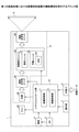
図2は、実施形態におけるプロジェクタ1の機能構成を例示するブロック図である。
FIG. 2 is a block diagram illustrating the functional configuration of the
図2に示されるように、プロジェクタ1は、電源4、メインスイッチSW5、操作部7、外部I/F9、システムコントロール部10、ファン20、光学エンジン15を有する。
As shown in FIG. 2, the
電源4は、商用電源に接続され、プロジェクタ1の内部回路用に電圧及び周波数を変換して、システムコントロール部10、ファン20、光学エンジン15等に給電する。
The
メインスイッチSW5は、ユーザによるプロジェクタ1のON/OFF操作に用いられる。電源4が電源コード等を介して商用電源に接続された状態で、メインスイッチSW5がONに操作されると、電源4がプロジェクタ1の各部への給電を開始し、メインスイッチSW5がOFFに操作されると、電源4がプロジェクタ1の各部への給電を停止する。
The main switch SW5 is used for the ON / OFF operation of the
操作部7は、ユーザによる各種操作を受け付けるボタン等であり、例えばプロジェクタ1の上面に設けられている。操作部7は、例えば投射画像の大きさ、色調、ピント調整等のユーザによる操作を受け付ける。操作部7が受け付けたユーザ操作は、システムコントロール部10に送られる。
The operation unit 7 is a button or the like that receives various operations by the user, and is provided on the upper surface of the
外部I/F9は、例えばパソコン、デジタルカメラ等に接続される接続端子を有し、接続された機器から送信される画像データをシステムコントロール部10に出力する。
The external I /
システムコントロール部10は、画像制御部11、移動制御部12を有する。システムコントロール部10は、例えばCPU,ROM,RAM等を含み、CPUがRAMと協働してROMに記憶されているプログラムを実行することで、各部の機能が実現される。
The
画像制御部11は、画像制御手段の一例であり、外部I/F9から入力される画像データに基づいて光学エンジン15の画像表示ユニット50に設けられているデジタルマイクロミラーデバイスDMD(Digital Micromirror Device(以下、単に「DMD」という))551を制御し、スクリーンSに投射する画像を生成する。
The
移動制御部12は、移動制御手段の一例であり、画像表示ユニット50において移動可能に設けられている可動ユニット55を移動させ、可動ユニット55に設けられているDMD551の位置を制御する。
The
ファン20は、システムコントロール部10に制御されて回転し、光学エンジン15の光源30を冷却する。
The
光学エンジン15は、光源30、照明ユニット40、画像表示ユニット50、投射光学ユニット60を有し、システムコントロール部10に制御されてスクリーンSに画像を投射する。
The
光源30は、例えば水銀高圧ランプ、キセノンランプ、LED等であり、システムコントロール部10により制御され、照明ユニット40に光を照射する。
The
照明ユニット40は、例えばカラーホイール、ライトトンネル、リレーレンズ等を有し、光源30から照射された光を画像表示ユニット50に設けられているDMD551に導く。
The
画像表示ユニット50は、固定支持されている固定ユニット51、固定ユニット51に対して移動可能に設けられている可動ユニット55を有する。可動ユニット55は、DMD551を有し、システムコントロール部10の移動制御部12によって固定ユニット51に対する位置が制御される。DMD551は、画像生成手段の一例であり、システムコントロール部10の画像制御部11により制御され、照明ユニット40によって導かれた光を変調して投射画像を生成する。
The
投射光学ユニット60は、例えば複数の投射レンズ、ミラー等を有し、画像表示ユニット50のDMD551によって生成される画像を拡大してスクリーンSに投射する。
The projection
<光学エンジンの構成>
次に、プロジェクタ1の光学エンジン15の各部の構成について説明する。
<Optical engine configuration>
Next, the configuration of each part of the
図3は、実施形態における光学エンジン15を例示する斜視図である。光学エンジン15は、図3に示されるように、光源30、照明ユニット40、画像表示ユニット50、投射光学ユニット60を有し、プロジェクタ1の内部に設けられている。
FIG. 3 is a perspective view illustrating the
光源30は、照明ユニット40の側面に設けられ、X2方向に光を照射する。照明ユニット40は、光源30から照射された光を、下部に設けられている画像表示ユニット50に導く。画像表示ユニット50は、照明ユニット40によって導かれた光を用いて投射画像を生成する。投射光学ユニット60は、照明ユニット40の上部に設けられ、画像表示ユニット50によって生成された投射画像をプロジェクタ1の外部に投射する。
The
なお、本実施形態の光学エンジン15は、光源30から照射される光を用いて上方に画像を投射するように構成されているが、水平方向に画像を投射するような構成であってもよい。
The
[照明ユニット]
図4は、実施形態における照明ユニット40を例示する図である。
[Lighting unit]
FIG. 4 is a diagram illustrating the
図4に示されるように、照明ユニット40は、カラーホイール401、ライトトンネル402、リレーレンズ403,404、シリンダミラー405、凹面ミラー406を有する。
As shown in FIG. 4, the
カラーホイール401は、例えば周方向の異なる部分にR(レッド)、G(グリーン)、B(ブルー)の各色のフィルタが設けられている円盤である。カラーホイール401は、高速回転することで、光源30から照射される光を、RGB各色に時分割する。
The
ライトトンネル402は、例えば板ガラス等の貼り合わせによって四角筒状に形成されている。ライトトンネル402は、カラーホイール401を透過したRGB各色の光を、内面で多重反射することで輝度分布を均一化してリレーレンズ403,404に導く。
The
リレーレンズ403,404は、ライトトンネル402から出射された光の軸上色収差を補正しつつ集光する。
The
シリンダミラー405及び凹面ミラー406は、リレーレンズ403,404から出射された光を、画像表示ユニット50に設けられているDMD551に反射する。DMD551は、凹面ミラー406からの反射光を変調して投射画像を生成する。
The
[投射光学ユニット]
図5は、実施形態における投射光学ユニット60の内部構成を例示する図である。
[Projection optics unit]
FIG. 5 is a diagram illustrating the internal configuration of the projection
図5に示されるように、投射光学ユニット60は、投射レンズ601、折り返しミラー602、曲面ミラー603がケースの内部に設けられている。
As shown in FIG. 5, the projection
投射レンズ601は、複数のレンズを有し、画像表示ユニット50のDMD551によって生成された投射画像を、折り返しミラー602に結像させる。折り返しミラー602及び曲面ミラー603は、結像された投射画像を拡大するように反射して、プロジェクタ1の外部のスクリーンS等に投射する。
The
[画像表示ユニット]
図6は、実施形態における画像表示ユニット50を例示する斜視図である。また、図7は、実施形態における画像表示ユニット50を例示する側面図である。
[Image display unit]
FIG. 6 is a perspective view illustrating the
図6及び図7に示されるように、画像表示ユニット50は、固定支持されている固定ユニット51、固定ユニット51に対して移動可能に設けられている可動ユニット55を有する。
As shown in FIGS. 6 and 7, the
固定ユニット51は、第1固定板としてのトッププレート511、第2固定板としてのベースプレート512を有する。固定ユニット51は、トッププレート511とベースプレート512とが所定の間隙を介して平行に設けられており、照明ユニット40の下部に固定される。
The fixing
可動ユニット55は、DMD551、第1可動板としての可動プレート552、第2可動板としての結合プレート553、ヒートシンク554を有し、固定ユニット51に移動可能に支持されている。
The
可動プレート552は、固定ユニット51のトッププレート511とベースプレート512との間に設けられ、固定ユニット51によってトッププレート511及びベースプレート512と平行且つ表面に平行な方向に移動可能に支持されている。
The
結合プレート553は、固定ユニット51のベースプレート512を間に挟んで可動プレート552に固定されている。結合プレート553は、上面側にDMD551が固定して設けられ、下面側にヒートシンク554が固定されている。結合プレート553は、可動プレート552に固定されることで、可動プレート552、DMD551、及びヒートシンク554と共に固定ユニット51に移動可能に支持されている。
The
DMD551は、結合プレート553の可動プレート552側の面に設けられ、可動プレート552及び結合プレート553と共に移動可能に設けられている。DMD551は、可動式の複数のマイクロミラーが格子状に配列された画像生成面を有する。DMD551の各マイクロミラーは、鏡面がねじれ軸周りに傾動可能に設けられており、システムコントロール部10の画像制御部11から送信される画像信号に基づいてON/OFF駆動される。
The
マイクロミラーは、例えば「ON」の場合には、光源30からの光を投射光学ユニット60に反射するように傾斜角度が制御される。また、マイクロミラーは、例えば「OFF」の場合には、光源30からの光を不図示のOFF光板に向けて反射する方向に傾斜角度が制御される。
When the micromirror is "ON", for example, the tilt angle is controlled so as to reflect the light from the
このように、DMD551は、画像制御部11から送信される画像信号によって各マイクロミラーの傾斜角度が制御され、光源30から照射されて照明ユニット40を通った光を変調して投射画像を生成する。
In this way, the
ヒートシンク554は、放熱手段の一例であり、少なくとも一部分がDMD551に当接するように設けられている。ヒートシンク554は、移動可能に支持される結合プレート553にDMD551と共に設けられることで、DMD551に当接して効率的に冷却することが可能になっている。このような構成により、本実施形態のプロジェクタ1では、ヒートシンク554がDMD551の温度上昇を抑制し、DMD551の温度上昇による動作不良や故障等といった不具合の発生が低減されている。
The
(固定ユニット)
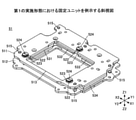
図8は、実施形態における固定ユニット51を例示する斜視図である。また、図9は、実施形態における固定ユニット51を例示する分解斜視図である。
(Fixed unit)
FIG. 8 is a perspective view illustrating the fixed
図8及び図9に示されるように、固定ユニット51は、トッププレート511、ベースプレート512を有する。
As shown in FIGS. 8 and 9, the fixing
トッププレート511及びベースプレート512は、平板状部材から形成され、それぞれ可動ユニット55のDMD551に対応する位置に中央孔513,514が設けられている。また、トッププレート511及びベースプレート512は、複数の支柱515によって、所定の間隙を介して平行に設けられている。
The
支柱515は、図9に示されるように、上端部がトッププレート511に形成されている支柱孔516に圧入され、雄ねじ溝が形成されている下端部がベースプレート512に形成されている支柱孔517に挿入される。支柱515は、トッププレート511とベースプレート512との間に一定の間隔を形成し、トッププレート511とベースプレート512とを平行に支持する。
As shown in FIG. 9, the
また、トッププレート511及びベースプレート512には、支持球体521を回転可能に保持する支持孔522,526がそれぞれ複数形成されている。
Further, a plurality of support holes 522 and 526 for rotatably holding the
トッププレート511の支持孔522には、内周面に雌ねじ溝を有する円筒状の保持部材523が挿入される。保持部材523は、支持球体521を回転可能に保持し、位置調整ねじ524が上から挿入される。ベースプレート512の支持孔526は、下端側が蓋部材527によって塞がれ、支持球体521を回転可能に保持する。
A cylindrical holding
トッププレート511及びベースプレート512の支持孔522,526に回転可能に保持される支持球体521は、それぞれトッププレート511とベースプレート512との間に設けられる可動プレート552に当接し、可動プレート552を移動可能に支持する。
The
図10は、実施形態における固定ユニット51による可動プレート552の支持構造を説明するための図である。また、図11は、図10に示されるA部分の概略構成を例示する部分拡大図である。
FIG. 10 is a diagram for explaining a support structure of the
図10及び図11に示されるように、トッププレート511では、支持孔522に挿入される保持部材523によって支持球体521が回転可能に保持されている。また、ベースプレート512では、下端側が蓋部材527によって塞がれている支持孔526によって支持球体521が回転可能に保持されている。
As shown in FIGS. 10 and 11, in the
各支持球体521は、支持孔522,526から少なくとも一部分が突出するように保持され、トッププレート511とベースプレート512との間に設けられる可動プレート552に当接して支持する。可動プレート552は、回転可能に設けられている複数の支持球体521により、トッププレート511及びベースプレート512と平行且つ表面に平行な方向に移動可能に両面から支持される。
Each
また、トッププレート511側に設けられている支持球体521は、可動プレート552とは反対側で当接する位置調整ねじ524の位置に応じて、保持部材523の下端からの突出量が変化する。例えば、位置調整ねじ524がZ1方向に変位すると、支持球体521の突出量が減り、トッププレート511と可動プレート552との間隔が小さくなる。また、例えば、位置調整ねじ524がZ2方向に変位すると、支持球体521の突出量が増え、トッププレート511と可動プレート552との間隔が大きくなる。
Further, the amount of protrusion of the
このように、位置調整ねじ524を用いて支持球体521の突出量を変化させることで、トッププレート511と可動プレート552との間隔を適宜調整できる。
In this way, by changing the amount of protrusion of the
また、図8及び図9に示されるように、トッププレート511のベースプレート512側の面には、磁石531,532,533,534が設けられている。
Further, as shown in FIGS. 8 and 9,
図12は、実施形態におけるトッププレート511を例示する底面図である。図12に示されるように、トッププレート511のベースプレート512側の面には、磁石531,532,533,534が設けられている。
FIG. 12 is a bottom view illustrating the
磁石531,532,533,534は、トッププレート511の中央孔513を囲むように4箇所に設けられている。磁石531,532,533,534は、それぞれ長手方向が平行になるように配置された直方体状の2つの磁石で構成され、それぞれ可動プレート552に及ぶ磁界を形成する。
磁石531,532,533,534は、それぞれ可動プレート552の上面に各磁石531,532,533,534に対向して設けられているコイルとで、可動プレート552を移動させる移動手段を構成する。
The
なお、上記した固定ユニット51に設けられる支柱515、支持球体521の数や位置等は、可動プレート552を移動可能に支持できればよく、本実施形態に例示される構成に限られるものではない。
It should be noted that the number and positions of the
(可動ユニット)
図13は、実施形態における可動ユニット55を例示する斜視図である。また、図14は、実施形態における可動ユニット55を例示する分解斜視図である。
(Movable unit)
FIG. 13 is a perspective view illustrating the
図13及び図14に示されるように、可動ユニット55は、DMD551、可動プレート552、結合プレート553、ヒートシンク554、保持部材555、DMD基板557を有し、固定ユニット51に対して移動可能に支持されている。
As shown in FIGS. 13 and 14, the
可動プレート552は、上記したように、固定ユニット51のトッププレート511とベースプレート512との間に設けられ、複数の支持球体521により表面に平行な方向に移動可能に支持される。
As described above, the
図15は、実施形態における可動プレート552を例示する斜視図である。
FIG. 15 is a perspective view illustrating the
図15に示されるように、可動プレート552は、平板状の部材から形成され、DMD基板557に設けられるDMD551に対応する位置に中央孔570を有し、中央孔570の周囲にコイル581,582,583,584が設けられている。
As shown in FIG. 15, the
コイル581,582,583,584は、それぞれZ1Z2方向に平行な軸を中心として電線が巻き回されることで形成され、可動プレート552のトッププレート511側の面に形成されている凹部に設けられてカバーで覆われている。コイル581,582,583,584は、それぞれトッププレート511の磁石531,532,533,534とで、可動プレート552を移動させる移動手段を構成する。
The
トッププレート511の磁石531,532,533,534と、可動プレート552のコイル581,582,583,584とは、可動ユニット55が固定ユニット51に支持された状態で、それぞれ対向する位置に設けられている。コイル581,582,583,584に電流が流されると、磁石531,532,533,534によって形成される磁界により、可動プレート552を移動させる駆動力となるローレンツ力が発生する。
The
可動プレート552は、磁石531,532,533,534とコイル581,582,583,584との間で発生する駆動力としてのローレンツ力を受けて、固定ユニット51に対して、XY平面において直線的又は回転するように変位する。
The
各コイル581,582,583,584に流される電流の大きさ及び向きは、システムコントロール部10の移動制御部12によって制御される。移動制御部12は、各コイル581,582,583,584に流す電流の大きさ及び向きによって、可動プレート552の移動(回転)方向、移動量や回転角度等を制御する。
The magnitude and direction of the current flowing through each
本実施形態では、第1駆動手段として、コイル581及び磁石531と、コイル584及び磁石534とが、X1X2方向に対向して設けられている。コイル581及びコイル584に電流が流されると、図15に示されるようにX1方向又はX2のローレンツ力が発生する。可動プレート552は、コイル581及び磁石531と、コイル584及び磁石534とにおいて発生するローレンツ力により、X1方向又はX2方向に移動する。
In the present embodiment, as the first driving means, the
また、本実施形態では、第2駆動手段として、コイル582及び磁石532と、コイル583及び磁石533とが、X1X2方向に並んで設けられ、磁石532及び磁石533は、磁石531及び磁石534とは長手方向が直交するように配置されている。このような構成において、コイル582及びコイル583に電流が流されると、図15に示されるようにY1方向又はY2方向のローレンツ力が発生する。
Further, in the present embodiment, as the second driving means, the
可動プレート552は、コイル582及び磁石532と、コイル583及び磁石533とにおいて発生するローレンツ力により、Y1方向又はY2方向に移動する。また、可動プレート552は、コイル582及び磁石532と、コイル583及び磁石533とで反対方向に発生するローレンツ力により、XY平面において回転するように変位する。
The
例えば、コイル582及び磁石532においてY1方向のローレンツ力が発生し、コイル583及び磁石533においてY2方向のローレンツ力が発生するように電流が流されると、可動プレート552は、上面視で時計回り方向に回転するように変位する。また、コイル582及び磁石532においてY2方向のローレンツ力が発生し、コイル583及び磁石533においてY1方向のローレンツ力が発生するように電流が流されると、可動プレート552は、上面視で反時計回り方向に回転するように変位する。
For example, when a current is passed so that a Lorentz force in the Y1 direction is generated in the
また、可動プレート552には、固定ユニット51の支柱515に対応する位置に、可動範囲制限孔571が設けられている。可動範囲制限孔571は、固定ユニット51の支柱515が挿入され、例えば振動や何らかの異常等により可動プレート552が大きく移動した時に支柱515に接触することで、可動プレート552の可動範囲を制限する。
Further, the
以上で説明したように、本実施形態では、システムコントロール部10の移動制御部12が、コイル581,582,583,584に流す電流の大きさや向きを制御することで、可動範囲内で可動プレート552を任意の位置に移動させることができる。
As described above, in the present embodiment, the
なお、移動手段としての磁石531,532,533,534及びコイル581,582,583,584の数、位置等は、可動プレート552を任意の位置に移動させることが可能であれば、本実施形態とは異なる構成であってもよい。例えば、移動手段としての磁石は、トッププレート511の上面に設けられてもよく、ベースプレート512の何れかの面に設けられてもよい。また、例えば、磁石が可動プレート552に設けられ、コイルがトッププレート511又はベースプレート512に設けられてもよい。
The number, position, etc. of the
また、可動範囲制限孔571の数、位置及び形状等は、本実施形態に例示される構成に限られない。例えば、可動範囲制限孔571は一つであってもよく、複数であってもよい。また、可動範囲制限孔571の形状は、例えば長方形や円形等、本実施形態とは異なる形状であってもよい。
Further, the number, position, shape, and the like of the movable
固定ユニット51によって移動可能に支持される可動プレート552の下面側(ベースプレート512側)には、図13に示されるように、結合プレート553が固定されている。結合プレート553は、平板状部材から形成され、DMD551に対応する位置に中央孔を有し、周囲に設けられている折り曲げ部分が3本のねじ591によって可動プレート552の下面に固定されている。
As shown in FIG. 13, the
図16は、可動プレート552が外された可動ユニット55を例示する斜視図である。
FIG. 16 is a perspective view illustrating the
図16に示されるように、結合プレート553には、上面側にDMD551、下面側にヒートシンク554が設けられている。結合プレート553は、可動プレート552に固定されることで、DMD551、ヒートシンク554と共に、可動プレート552に伴って固定ユニット51に対して移動可能に設けられている。
As shown in FIG. 16, the
DMD551は、DMD基板557に設けられており、DMD基板557が保持部材555と結合プレート553との間で挟み込まれることで、結合プレート553に固定されている。保持部材555、DMD基板557、結合プレート553、ヒートシンク554は、図14及び図16に示されるように、固定部材としての段付ねじ560及び押圧手段としてのばね561によって重ねて固定されている。
The
図17は、実施形態における可動ユニット55のDMD保持構造について説明する図である。図17は、可動ユニット55の側面図であり、可動プレート552及び結合プレート553は図示が省略されている。
FIG. 17 is a diagram illustrating a DMD holding structure of the
図17に示されるように、ヒートシンク554は、結合プレート553に固定された状態で、DMD基板557に設けられている貫通孔からDMD551の下面に当接する突出部554aを有する。なお、ヒートシンク554の突出部554aは、DMD基板557の下面であって、DMD551に対応する位置に当接するように設けられてもよい。
As shown in FIG. 17, the
また、DMD551の冷却効果を高めるために、ヒートシンク554の突出部554aとDMD551との間に弾性変形可能な伝熱シートが設けられてもよい。伝熱シートによりヒートシンク554の突出部554aとDMD551との間の熱伝導性が向上し、ヒートシンク554によるDMD551の冷却効果が向上する。
Further, in order to enhance the cooling effect of the
上記したように、保持部材555、DMD基板557、ヒートシンク554は、段付きねじ560及びばね561によって重ねて固定されている。段付きねじ560が締められると、ばね561がZ1Z2方向に圧縮され、図17に示されるZ1方向の力F1がばね561から生じる。ばね561から生じる力F1により、ヒートシンク554はZ1方向に力F2でDMD551に押圧されることとなる。
As described above, the holding
本実施形態では、段付きねじ560及びばね561は4箇所に設けられており、ヒートシンク554にかかる力F2は、4つのばね561に生じる力F1を合成したものに等しい。また、ヒートシンク554からの力F2は、DMD551が設けられているDMD基板557を保持する保持部材555に作用する。この結果、保持部材555には、ヒートシンク554からの力F2に相当するZ2方向の反力F3が生じ、保持部材555と結合プレート553との間でDMD基板557を保持できるようになる。
In the present embodiment, the stepped
段付きねじ560及びばね561には、保持部材555に生じる力F3からZ2方向の力F4が作用する。ばね561は、4箇所に設けられているため、それぞれに作用する力F4は、保持部材555に生じる力F3の4分の1に相当し、力F1と釣り合うこととなる。
A force F4 in the Z2 direction from the force F3 generated on the holding
また、保持部材555は、図17において矢印Bで示されるように撓むことが可能な部材で板ばね状に形成されている。保持部材555は、ヒートシンク554の突出部554aに押圧されて撓み、ヒートシンク554をZ2方向に押し返す力が生じることで、DMD551とヒートシンク554との接触をより強固に保つことができる。
Further, the holding
可動ユニット55は、以上で説明したように、可動プレート552と、DMD551及びヒートシンク554を有する結合プレート553とが、固定ユニット51によって移動可能に支持されている。可動ユニット55の位置は、システムコントロール部10の移動制御部12によって制御される。また、可動ユニット55には、DMD551に当接するヒートシンク554が設けられており、DMD551の温度上昇に起因する動作不良や故障といった不具合の発生が防止されている。
As described above, in the
<画像投射>
上記したように、本実施形態のプロジェクタ1において、投射画像を生成するDMD551は、可動ユニット55に設けられており、システムコントロール部10の移動制御部12によって可動ユニット55と共に位置が制御される。
<Image projection>
As described above, in the
移動制御部12は、例えば、画像投射時にフレームレートに対応する所定の周期で、DMD551の複数のマイクロミラーの配列間隔未満の距離だけ離れた複数の位置の間を高速移動するように可動ユニット55の位置を制御する。このとき、画像制御部11は、それぞれの位置に応じてシフトした投射画像を生成するようにDMD551に画像信号を送信する。
The
例えば、移動制御部12は、X1X2方向及びY1Y2方向にDMD551のマイクロミラーの配列間隔未満の距離だけ離れた位置P1と位置P2との間で、DMD551を所定の周期で往復移動させる。このとき、画像制御部11が、それぞれの位置に応じてシフトした投射画像を生成するようにDMD551を制御することで、投射画像の解像度を、DMD551の解像度の約2倍にすることが可能になる。また、DMD551の移動位置を増やすことで、投射画像の解像度をDMD551の2倍以上にすることもできる。
For example, the
このように、移動制御部12が可動ユニット55と共にDMD551を所定の周期で移動させ、画像制御部11がDMD551に位置に応じた投射画像を生成させることで、DMD551の解像度以上の画像を投射することが可能になる。
In this way, the
また、本実施形態のプロジェクタ1では、移動制御部12がDMD551を可動ユニット55と共に回転するように制御することで、投射画像を縮小させることなく回転させることができる。例えばDMD551等の画像生成手段が固定されているプロジェクタでは、投射画像を縮小させなければ、投射画像の縦横比を維持しながら回転させることはできない。これに対して、本実施形態のプロジェクタ1では、DMD551を回転させることができるため、投射画像を縮小させることなく回転させて傾き等の調整を行うことが可能になっている。
Further, in the
以上で説明したように、本実施形態のプロジェクタ1では、DMD551が移動可能に構成されることで、投射画像の高解像度化が可能になっている。また、DMD551を冷却するヒートシンク554が、DMD551と共に可動ユニット55に搭載されていることで、DMD551に当接してより効率的に冷却することが可能になり、DMD551の温度上昇が抑制されている。したがって、プロジェクタ1では、DMD551の温度上昇に起因して発生する動作不良や故障といった不具合が低減される。
As described above, in the
(組み付け調整方法)
画像投射装置の製造時には、それぞれユニットとして組み付けられた照明ユニットと、画像表示ユニットと、投射光学ユニットとが組み合わせられ、画像投射装置における光学エンジンが組み付けられる。
(Assembly adjustment method)
At the time of manufacturing the image projection device, the lighting unit assembled as each unit, the image display unit, and the projection optical unit are combined, and the optical engine in the image projection device is assembled.
各ユニットを構成するDMDやレンズ等の部品には、公差範囲内においても多少の製造ばらつきがある場合がある。そのため、光学エンジンの組み付けの際には、投射画像の位置やフォーカスが光学エンジン毎に調整され、部品の製造ばらつきの影響が取り除かれる。組み付け調整では、照明ユニットと画像表示ユニットとの間の距離、或いは照明ユニットと投射光学ユニットとの間の距離等が調整される。 Parts such as DMDs and lenses constituting each unit may have some manufacturing variations even within the tolerance range. Therefore, when assembling the optical engine, the position and focus of the projected image are adjusted for each optical engine, and the influence of manufacturing variations of parts is removed. In the assembly adjustment, the distance between the lighting unit and the image display unit, the distance between the lighting unit and the projection optical unit, and the like are adjusted.
このような光学エンジンの組み付け調整について、以下に、照明ユニットと画像表示ユニットとを組み付ける場合を例に説明する。また比較のため、先ず、本実施形態が適用されない場合の組み付け調整を、図18を参照して説明する。次に本実施形態の組み付け調整を、図19~22を参照して説明する。 The assembly adjustment of such an optical engine will be described below by taking as an example the case where the lighting unit and the image display unit are assembled. Further, for comparison, first, the assembly adjustment in the case where the present embodiment is not applied will be described with reference to FIG. Next, the assembly adjustment of the present embodiment will be described with reference to FIGS. 19 to 22.
比較にあたっての便宜のため、本実施形態が適用されない場合であっても、本実施形態の画像投射装置1と同等の機能を有するユニット、部品等には同一の部品番号が付されている。
For convenience of comparison, even if the present embodiment is not applied, the same part number is assigned to the units, parts, and the like having the same functions as the
図18は、本実施形態が適用されない場合の光学エンジンの組み付け調整の様子を示す図である。 FIG. 18 is a diagram showing a state of assembly adjustment of the optical engine when the present embodiment is not applied.
図18の(a)は、光学エンジン15の全体構成を示す斜視図である。光学エンジン15は、照明ユニット40と、画像表示ユニット50と、投射光学ユニット60とを有する。図18(a)では、照明ユニット40と投射光学ユニット60は既に組み付けられており、照明ユニット40に画像表示ユニット50が組み付ける直前の状態が示されている。
FIG. 18A is a perspective view showing the overall configuration of the
画像表示ユニット50がZ1方向に移動され、照明ユニット40の実線の丸421で示された部分に、画像表示ユニット50の備えるDMD551が配置されるようにして組み付けられる。
The
図18(b)は、図18(a)に実線の丸421で示された照明ユニット40の部分を拡大して表示する図である。
FIG. 18B is an enlarged view showing a portion of the
図18(b)に示されているように、照明ユニット40の有する筐体422には、画像表示ユニット50が組み付けられた際にDMD551の画像生成面が配置される位置に、矩形の開口423が形成されている。また筐体422には、開口423の周囲に、DMD基準面424a、424b、及び424cと、DMD主基準軸425と、DMD従基準軸426とが形成されている。
As shown in FIG. 18B, the
DMD基準面424a、424b、及び424cは、照明ユニット40に画像表示ユニット50を組み付ける際に、DMD551の面の一部を当接させる基準面である。当接させることで、Z1Z2方向における照明ユニット40と画像表示ユニット50の距離合わせ、及び両者の傾きの抑制が図られる。
The
DMD主基準軸425、及びDMD従基準軸426は、照明ユニット40に画像表示ユニット50を組み付ける際に、DMD551の保持部材に設けられた基準穴に嵌合させるピン状部材である。嵌合させることで、X1X2方向、及びY1Y2方向における照明ユニット40と画像表示ユニット50の位置合わせが図られる。DMD主基準軸425は、X1X2方向、及びY1Y2方向における照明ユニット40と画像表示ユニット50の位置合わせにおいて主となる基準軸である。
The DMD
図18(c)は、図18(a)に示された画像表示ユニット50をZ2方向に視た斜視図である。図18(c)に示されているように、画像表示ユニット50は、DMD551と、保持部材555と、ヒートシンク554等を有する。DMD551は、保持部材555に固定される。ヒートシンク554は、保持部材555のDMD551が固定された面の反対側の面に固定される。
FIG. 18C is a perspective view of the
保持部材555において、DMD551の周囲には、DMD主基準穴5511と、DMD従基準穴5512とが形成されている。上述のように、DMD主基準軸425はDMD主基準穴5511に嵌合され、またDMD従基準軸426はDMD従基準穴5512に嵌合される。
In the holding
図18(d)は、図18(a)に破線の丸501で示された画像表示ユニット50の部分を拡大して表示する図である。この部分は、画像表示ユニット50を照明ユニット40にねじ止めして固定するための「ねじ部」である。ねじ部は、X1X2方向、及びY1Y2方向を含む平面内で4箇所に設けられている。4箇所のねじ部のうちの1つが、図18(d)に拡大表示されている。
FIG. 18D is a diagram in which the portion of the
図18(d)に示されているように、ねじ部には、段付きねじ560とばね561が備えられている。照明ユニットに設けられた雌ねじ部に、段付きねじ560がばね561を介して結合することで、照明ユニット40に画像表示ユニット50が固定される。
As shown in FIG. 18 (d), the threaded portion is provided with a stepped
保持部材555、DMD基準面424a、424b、及び424c等の部品には、公差範囲内においても多少なりとも製造ばらつきがある場合がある。上記の構成では、このような製造ばらつきによって、照明ユニット40と画像表示ユニット50のZ1Z2方向の距離を所望の範囲内に合わせ、また両者の傾きを所望の範囲内に抑制することが困難になる場合がある。
Parts such as the holding
またX1X2方向及びY1Y2方向を含む平面内でDMD551を移動、又は回転させるために、上述した固定ユニット51、可動ユニット55等を設けた場合、部品点数の増加に伴い、さらに距離や傾きの誤差が生じやすくなる。
Further, when the above-mentioned
距離や傾きの誤差は、投射画像の全体、或いは部分に焦点ずれや歪みを生じさせる。また距離や傾きの誤差を抑えるように、DMD基準面422a~422c、保持部材555等の加工精度をさらに上げると、部品コストが増大する。
Distance and tilt errors cause defocus and distortion in the entire or portion of the projected image. Further, if the processing accuracy of the DMD reference surfaces 422a to 422c, the holding
図19は、本実施形態の光学エンジンの組み付け調整の様子の一例を説明する図である。 FIG. 19 is a diagram illustrating an example of how the optical engine of the present embodiment is assembled and adjusted.
図19(a)は、光学エンジン15の全体構成を示す斜視図である。光学エンジン15は、照明ユニット40と、画像表示ユニット50と、投射光学ユニット60とを有する。図18と同様に、図19(a)では、照明ユニット40と投射光学ユニット60は既に組み付けられており、照明ユニット40に画像表示ユニット50が組み付けられる直前の状態が示されている。
FIG. 19A is a perspective view showing the overall configuration of the
画像表示ユニット50がZ1方向に移動され、照明ユニット40の実線の丸411で示された部分に、画像表示ユニット50の備えるDMD551が配置されるようにして組み付けられる。
The
図19(b)は、図19(a)に実線の丸411で示された照明ユニット40の部分を拡大して表示する図である。
19 (b) is a diagram in which the portion of the
図19(b)に示されているように、照明ユニット40の有する筐体412には、画像表示ユニット50が組み付けられた際にDMD551の画像生成面が配置される位置に、矩形の開口413が形成されている。また筐体412には、開口413の周囲に、ユニット基準面414a、414b、414c、及び414dと、ユニット主基準軸415と、ユニット従基準軸416とが形成されている。
As shown in FIG. 19B, the
ユニット基準面414a、414b、414c、及び414dは、照明ユニット40に画像表示ユニット50を組み付ける際に、画像表示ユニット50のトッププレート511の面の一部を当接させる基準面である。当接させることで、Z1Z2方向における照明ユニット40と画像表示ユニット50の距離合わせ、及び両者の傾きの抑制が図られる。
The
ユニット基準面414a、414b、414c、及び414dを4つの微小な円形上の面とすることで、加工精度が要求される部分の面積が抑えられている。これにより画像表示ユニット50のトッププレート511に当接する筐体412の面全体を基準面にする場合と比較して、加工コストが抑制される。尚、基準面の数は4つに限定されず、任意の数であってよい。
By making the
またユニット基準面414aの中央部分には、雌ねじ穴414a1が形成されている。同様にユニット基準面414bの中央部分には雌ねじ穴414b1が形成され、ユニット基準面414cの中央部分には雌ねじ穴414c1が形成され、ユニット基準面414dの中央部分には雌ねじ穴414d1が形成されている。
Further, a female screw hole 414a1 is formed in the central portion of the
ユニット主基準軸41とユニット従基準軸414は、照明ユニット40に画像表示ユニット50を組み付ける際に、画像表示ユニット50のトッププレート511に設けられた基準穴に嵌合させるピン状部材である。嵌合させることで、X1X2方向、及びY1Y2方向における照明ユニット40と画像表示ユニット50の位置合わせが図られる。ユニット主基準軸415は、X1X2方向、及びY1Y2方向における照明ユニット40と画像表示ユニット50の位置合わせにおいて、主となる基準軸である。
The unit main reference shaft 41 and the unit slave reference shaft 414 are pin-shaped members that are fitted into reference holes provided in the
図19(c)は、図19(a)に示された画像表示ユニット50をZ2方向に視た斜視図である。画像表示ユニット50は、DMD551と、可動ユニット55と、固定ユニット51等を備える(図6参照)。
19 (c) is a perspective view of the
可動ユニット55は、可動プレート552と、結合プレート553と、ヒートシンク554等を備える。結合プレート553の一方の面にDMD551が固定され、他方の面にヒートシンク554が固定される。結合プレート553は、可動プレート552に固定されることで、DMD551、及びヒートシンク554と共に、可動プレート552に伴って固定ユニット51に対して移動可能である(図16参照)。
The
固定ユニット51は、トッププレート511を有する。トッププレート511を介して、画像表示ユニット50は、照明ユニット40に組み付けられる。
The fixing
図19(c)において、トッププレート511におけるDMD551の周囲には、ユニット主基準穴5111と、ユニット従基準穴5112とが形成されている。上述のように、ユニット主基準軸415はユニット主基準穴5111に嵌合され、またユニット従基準軸416はユニット従基準穴5112に嵌合される。
In FIG. 19C, a unit
図19(d)は、図19(c)に実線の丸503で示された装置取付ねじの部分を拡大して表示する図である。この部分は、画像表示ユニット50を照明ユニット40にねじ止めして固定するための「ねじ部」である。ねじ部はX1X2方向、及びY1Y2方向を含む平面内で4箇所に設けられている。4箇所のねじ部のうちの1つが、図19(d)に拡大表示されている。
FIG. 19 (d) is an enlarged view showing a portion of the device mounting screw shown by the
図19(d)に示されているように、ねじ部において、トッププレート511には、ねじ穴5113aが形成されている。照明ユニット40に画像表示ユニット50を組み付ける際に、取付ねじ5114aはねじ穴5113aに通され、雌ねじ穴414a1と結合する。同様に取付ねじ5114bはねじ穴5113bに通され、雌ねじ穴414b1と結合する。取付ねじ5114cはねじ穴5113cに通され、雌ねじ穴414c1と結合する。取付ねじ5114dはねじ穴5113dに通され、雌ねじ穴414d1と結合する。このように、トッププレート511は、筐体412にねじ止めされ、照明ユニット40に画像表示ユニット50が固定される。
As shown in FIG. 19D, a
図19(a)に戻り、破線の丸502で示された部品はスペーサを示している。スペーサは、照明ユニット40に画像表示ユニット50を固定する際に、両者の間に配置され、両者の間の距離を調整するために用いられる。
Returning to FIG. 19 (a), the part indicated by the
図19(e)は、図19(a)の破線の丸502の部分を拡大して表示する図である。図19(e)に示されているように、本実施形態では、リング状の3つのスペーサ5523a、5524a、及び5525aが用いられる。
19 (e) is a diagram in which the portion of the
照明ユニット40に画像表示ユニット50を固定する際に、スペーサ5523a、5524a、及び5525aはZ1Z2方向に重ねられる。そして重ねられたスペーサ5523a、5524a、及び5525aの中央の円形の開口部分を貫くように、取付ねじ5114aが通される。取付ねじ5114aは、スペーサ5523a、5524a、及び5525aを介して、雌ねじ穴414a1と結合する。これにより照明ユニット40に画像表示ユニット50が固定される。
When fixing the
スペーサ5523a、5524a、及び5525aは、互いに厚さが異なっている。例えばスペーサ5523aの厚さは250μmであり、スペーサ5524aの厚さは200μmであり、スペーサ5525aの厚さは150μmである。他にも厚さの異なるスペーサが複数用意され、照明ユニット40に画像表示ユニット50を固定する際に、両者の間に配置するスペーサの厚さを選択することで、両者の距離を調整することができる。
The
また本実施形態では、5523a、5524a、及び5525aの直径を、厚さに対応付けて互いに異ならせている。例えば、スペーサ5523a、スペーサ5524a、スペーサ5525aは、円形であり、スペーサ5523aの直径は15mmであり、スペーサ5524aの直径は10mmであり、スペーサ5525aの直径は5mmである。
Further, in the present embodiment, the diameters of 5523a, 5524a, and 5525a are made different from each other in correspondence with the thickness. For example, the
組み付け調整を行う作業者は、スペーサ5523aとスペーサ5524aとの間の50μmの厚さの違いを肉眼で識別することは困難である。しかしスペーサ5523aとスペーサ5524aの5mmの直径の違いであれば、一見で視認可能である。
It is difficult for the operator who performs the assembly adjustment to visually identify the difference in thickness of 50 μm between the
スペーサの厚さと直径との関係を予め規定しておけば、作業者は、スペーサの直径を目視で把握することで、スペーサの厚さを認識することができる。換言すると、作業者は、スペーサの厚さを視認することができる。例えば、上記のように、スペーサ5523a、5524a、及び5525aは、互いに比較して、面積が大きいほど、もしくは、直径が大きいほど、厚さも厚くなるように、構成されている。具体的には、直径が5mm大きいほど、厚さは50μm大きい。この関係を予め知ることで、スペーサ5523a、5524a、及び5525aの厚さの違い、および、それぞれの厚さを容易に視認することが可能である。特に、この実施例の場合、スペーサの円形の直径と、厚さとの間に比例の関係を持たせているので、スペーサ間の厚さの差が分かりやすくなっている。また、スペーサ5523a、5524a、及び5525aを、互いに比較して、面積が小さいほど、もしくは、直径が小さいほど、厚さが厚くなるように、構成しても、面積が大きいほど、もしくは、直径が大きいほど、厚さも厚くなるようにした場合と、同じ効果が得られる。
If the relationship between the thickness and the diameter of the spacer is specified in advance, the operator can recognize the thickness of the spacer by visually grasping the diameter of the spacer. In other words, the operator can visually recognize the thickness of the spacer. For example, as described above, the spacers 5523a, 5524a, and 5525a are configured so that the larger the area or the larger the diameter, the thicker the thickness of the spacers 5523a, 5524a, and 5525a. Specifically, the larger the diameter is 5 mm, the larger the thickness is 50 μm. By knowing this relationship in advance, it is possible to easily visually recognize the difference in thickness between the
スペーサは、取付ねじが設けられた4箇所に、取付ねじ毎に配置される。取付ねじ毎でスペーサの厚さを変えて、Z1Z2方向における画像表示ユニット50と照明ユニット40の傾きを調整することも可能である。
Spacers are arranged for each mounting screw at four locations where mounting screws are provided. It is also possible to adjust the inclination of the
このように照明ユニット40と画像表示ユニット50の間に、互いに厚さの異なる複数のスペーサを選択して配置することで、照明ユニット40と画像表示ユニット50の間の距離を調整できる。トッププレート511、ユニット基準面414a、414b、414c、及び414d等に製造ばらつきがあっても、照明ユニット40と画像表示ユニット50のZ1Z2方向の距離を所望の範囲内に合わせ、また両者の傾きを所望の範囲内に抑制するように調整することができる。
By selecting and arranging a plurality of spacers having different thicknesses between the
上記では、取付ねじが貫通可能なスペーサを、取付ねじ毎に配置する例を示したが、必ずしも貫通可能なスペーサでなくてもよいし、取付ねじ毎に配置されなくても構わない。 In the above, the example in which the spacer through which the mounting screw can penetrate is arranged for each mounting screw is shown, but it does not necessarily have to be a spacer that can penetrate, and it does not have to be arranged for each mounting screw.
また上記では、厚さの異なる3つのスペースを重ねて配置する例を示したが、スペーサを重ねる数に制限はなく、任意の数のスペーサを重ねて配置してもよい。 Further, in the above, an example in which three spaces having different thicknesses are stacked and arranged is shown, but the number of spacers to be stacked is not limited, and any number of spacers may be stacked and arranged.
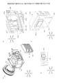
図20は、本実施形態の組み付け調整を実施するための調整装置の構成の一例を示す図である。図20(a)は調整装置の全体構成を示す斜視図である。図20(a)において、調整装置700は、ベース板701と、2軸直動機構702と、変位計703とを有する。
FIG. 20 is a diagram showing an example of the configuration of an adjusting device for carrying out the assembly adjustment of the present embodiment. FIG. 20A is a perspective view showing the overall configuration of the adjusting device. In FIG. 20A, the adjusting
ベース板701は、被調整物を保持する板部材である。ベース板701は、2軸直動機構702の備えるテーブルに固定される。
The
2軸直動機構702は、X1X2方向、及びY1Y2方向の2軸方向に進退可能な直動機構である。直動機構では、例えばステッピングモータ等のモータの回転運動がボールねじ等で直線運動に変換される。ボールねじにナットを介して接続したテーブルは、モータの回転により直動することができる。2軸直動機構702は、2つの直動機構が直交するように組合わされ、構成されている。2軸直動機構702は、テーブルに固定されたベース板701を、X1X2方向、及びY1Y2方向の2軸方向に進退させる。
The two-axis
変位計703は、Z1Z2方向の位置を測定し、測定結果を出力する。尚、以下では、Z1Z2方向の位置を「高さ」と称する。変位計701は、例えばレーザ変位計であり、被調整物の所定の箇所に向けてレーザビームを照射する。変位計701は、被調整物の反射光を受光することで、被調整物の所定の箇所の高さを測定する。
The
変位計703は、ベース板701に設けられた矩形の穴である測定開口部701aを通じて、ベース板701に固定される被調整物の所定の箇所に向けてレーザビームを照射する。測定の際は、X1X2方向、及びY1Y2方向におけるベース板701の位置が2軸直動機構702により変化させられ、被調整物における高さの測定箇所が変更される。
The
本実施形態の組み付け調整においては、先ずマスタ治具710が調整装置700のベース板701にセットされる。ここで、マスタ治具710は、Z1Z2方向の位置の基準となる面を備えた治具である。
In the assembly adjustment of the present embodiment, the
図20(b)は、図20(a)に示されるマスタ治具710をZ2方向に視た場合の斜視図である。図20(b)に示されるように、マスタ治具710は、マスタデータム面位置711a、711b、及び711cを有する。マスタデータム面位置711a、711b、及び711cは、それぞれ相互の高さが等しくなるように調整されて加工された面であり、本実施形態の組み付け調整において、高さの基準となる面である。
20 (b) is a perspective view of the
マスタ治具710は、図20(a)に破線の矢印で示した4箇所で、ベース板701に固定される。マスタデータム面位置711a、711b、及び711cの高さが変位計701で測定され、それぞれの測定値が記録される。その後、ベース板701からマスタ治具710は取り外され、次に被調整物である画像表示ユニット50がベース板701にセットされる。
The
図21は、調整装置700による画像表示ユニット50の組み付け調整の様子の一例を説明する図である。図21(a)は、画像表示ユニット50が調整装置700にセットされる直前の様子を示す斜視図である。図21(b)は、図21(a)に示されている画像表示ユニット50をZ2方向に視た斜視図である。
FIG. 21 is a diagram illustrating an example of how the
図21(b)において、DMD551が固定された基板518には、DMDデータム面位置712a、712b、及び712cが形成されている。また上述のように、トッププレート511には、ユニット主基準穴5111と、ユニット従基準穴5112とが形成されている。
In FIG. 21B, DMD
ユニット主基準穴5111と、ユニット従基準穴5112により、X1X2方向、及びY1Y2方向の位置合わせがなされて、画像表示ユニット50はベース板701に固定される。一方、図21(c)は、図21(a)の破線の丸704の部分を拡大して表示する図である。図21(c)では、3つのリング状のスペーサ5523、5524、及び5525が例示されている。スペーサ5523、5524、及び5525は、Z1Z2方向に重ねられ、画像表示ユニット50における4箇所の取付ねじの位置毎で、画像表示ユニット50とベース板701の間に配置される。
The unit
組み付け調整において、画像表示ユニット50をベース板701にセットする際は、先ず標準となる厚さのスペーサの組み合わせが使用される。標準のスペーサが組み合わされて配置された状態で、画像表示ユニット50はベース板701に固定される。変位計703により、DMDデータム面位置712a、712b、及び712cの高さが測定される。
In the assembly adjustment, when the
次に、DMDデータム面位置712aとマスタデータム面位置711aで、高さの測定値が比較される。両者にずれがある場合は、ずれを補正するように、スペーサの厚さの組み合わせが選択される。同様に、DMDデータム面位置712bとマスタデータム面位置711bで、高さの測定値が比較され、両者にずれがある場合は、ずれを補正するように、スペーサの厚さの組み合わせが選択される。またDMDデータム面位置712cとマスタデータム面位置711cで、高さの測定値が比較され、両者にずれがある場合は、ずれを補正するように、スペーサの厚さの組み合わせが選択される。
Next, the height measurements are compared at the DMD
この時に、上述したように、作業者は、スペーサの直径等の大きさの違いを視認することで、スペーサの厚さの違いを視認しながら、スペーサの厚さの組み合わせを選択することができる。 At this time, as described above, the operator can select a combination of spacer thicknesses while visually recognizing the difference in spacer thickness by visually recognizing the difference in size such as the diameter of the spacer. ..
取付ねじ毎で、厚さの補正されたスペーサが配置され、画像表示ユニット50は照明ユニット40に組み付けられる。これにより、画像表示ユニット50と照明ユニット40との距離が調整されて、光学エンジン15が組み付けられる。
A spacer whose thickness has been corrected is arranged for each mounting screw, and the
尚、上記ではマスタデータム面位置とDMDデータム面位置の数がそれぞれ3つの場合を示したが、これには限定されず、任意の数にしてもよい。 In the above, the number of master datum surface positions and the number of DMD datum surface positions are each three, but the number is not limited to this and may be any number.
図22は、本実施形態の調整方法の一例を示すフローチャートである。 FIG. 22 is a flowchart showing an example of the adjustment method of the present embodiment.
先ず、作業者は、マスタ治具710を調整装置700のベース板701にセットする(ステップS221)。
First, the operator sets the
次に、作業者は、マスタデータム面位置711a、711b、及び711cのそれぞれの高さを変位計703により測定し、測定値を記録する(ステップS222)。
Next, the operator measures the heights of the master
次に、作業者は、マスタ治具710を調整装置700から取り外す(ステップS223)。
Next, the operator removes the
次に、作業者は、画像表示ユニット50の取付ねじの位置毎に標準のスペーサを配置して、画像表示ユニット50を調整装置700のベース板701にセットする(ステップS224)。
Next, the operator arranges a standard spacer for each position of the mounting screw of the
次に、作業者は、DMDデータム面位置712a、712b、及び712cのそれぞれの高さを変位計703により測定し、測定値を記録する(ステップS225)。
Next, the operator measures the heights of the DMD
次に、作業者は、マスタデータム面位置711aとDMDデータム面位置712a、マスタデータム面位置711bとDMDデータム面位置712b、及びマスタデータム面位置711aとDMDデータム面位置712aを、それぞれ比較する。両者に差がある場合、差を補正するようにスペーサの組み合わせが選択される。作業者は、スペーサの大きさの違いを視認し、スペーサの厚さの違いを視認しながら、スペーサの組み合わせを選択し、決定する(ステップS226)。
Next, the operator compares the master
次に、作業者は、画像表示ユニット50を調整装置700から取り外して、決定した組み合わせにスペーサを交換する(ステップS227)。
Next, the operator removes the
次に、作業者は、取付ねじ毎に、決定した組合せのスペーサを配置し、画像表示ユニット50を照明ユニット40に組み付ける(ステップS228)。
Next, the operator arranges the spacers of the determined combination for each mounting screw, and assembles the
このようにして、作業者は、画像表示ユニット50と照明ユニット40との距離を調整して、光学エンジン15を組み付けることができる。
In this way, the operator can adjust the distance between the
尚、ステップS227以降は、適宜変更可能である。例えば、スペーサを交換した後、再度、画像表示ユニット50を調整装置700のベース板701にセットする。そして変位計703でDMDデータム面位置712a、712b、及び712cの高さを測定して、所望の高さになっているか再確認してもよい。
In addition, after step S227, it can be changed as appropriate. For example, after replacing the spacer, the
以上説明してきたように、本実施形態によれば、照明ユニットと画像表示ユニットとの間に配置する厚さの異なる複数のスペーサを、厚さ方向に垂直な面の大きさが互いに異なるものとすることで、スペーサの厚さの違いが視認可能になる。これにより、照明ユニットと画像表示ユニットとの間の距離等の調整を、視認で効率的に行うことができる。また光学エンジンや画像投射装置の製造効率を向上させることができる。 As described above, according to the present embodiment, a plurality of spacers having different thicknesses arranged between the lighting unit and the image display unit have different sizes of surfaces perpendicular to the thickness direction. By doing so, the difference in the thickness of the spacer becomes visible. This makes it possible to visually and efficiently adjust the distance between the lighting unit and the image display unit. In addition, the manufacturing efficiency of the optical engine and the image projection device can be improved.
本実施形態では、照明ユニット40と画像表示ユニット50との間にスペーサを配置する例を示したが、これに限定はされない。例えば、照明ユニット40と投射光学ユニット60との間にスペーサを配置し、照明ユニット40と投射光学ユニット60の距離を同様に調整してもよい。
In the present embodiment, an example in which a spacer is arranged between the
また、カメラ等でスペーサを撮影することで、スペーサの厚さの違いを自動認識することも容易になる。従って、高価な測定装置を用いることなく、スペーサの厚さの違いを自動認識し、照明ユニットと投射光学ユニットとの間の距離等の調整を自動化することも可能となる。 Further, by photographing the spacer with a camera or the like, it becomes easy to automatically recognize the difference in the thickness of the spacer. Therefore, it is possible to automatically recognize the difference in the thickness of the spacer and automate the adjustment of the distance between the lighting unit and the projection optical unit without using an expensive measuring device.
[第2の実施形態]
第1の実施形態では、スペーサの直径等の大きさを変えることで、スペーサの厚さの違いを視認可能にする例を示したが、これに限定はされない。例えば、厚さ方向に垂直な面のスペーサの形状を変えて、スペーサの厚さの違いを視認可能にしてもよい。具体的には、厚さが250μmの形状を五角形とし、厚さが200μmのスペーサの形状を四角形とし、厚さが150μmのスペーサの形状を三角形にする等である。スペーサの形状を目視することで、スペーサの厚さの違いを認識することができる。
[Second Embodiment]
In the first embodiment, an example is shown in which the difference in the thickness of the spacer is made visible by changing the size such as the diameter of the spacer, but the present invention is not limited to this. For example, the shape of the spacer on the surface perpendicular to the thickness direction may be changed so that the difference in the thickness of the spacer can be visually recognized. Specifically, the shape of the spacer having a thickness of 250 μm is a pentagon, the shape of the spacer having a thickness of 200 μm is a quadrangle, the shape of the spacer having a thickness of 150 μm is a triangle, and the like. By visually observing the shape of the spacer, the difference in the thickness of the spacer can be recognized.
第1の実施形態のようにスペーサの大きさを異ならせた場合、大きさの差が小さいと一見では違いを認識することが難しい時がある。例えば、直径9mmのスペーサと直径10mmのスペーサの違いを一目で認識することは難しい場合がある。 When the sizes of the spacers are different as in the first embodiment, it may be difficult to recognize the difference at first glance if the difference in size is small. For example, it may be difficult to recognize the difference between a spacer having a diameter of 9 mm and a spacer having a diameter of 10 mm at a glance.
本実施形態によれば、スペーサの厚さごとで、厚さ方向に垂直な面のスペーサの形状を異ならせるために、スペーサの違いをより分かりやすくすることができる。つまりスペーサの厚さの違いをより容易に視認することができる。例えば、上記のように、互いに比較して、形状の角数が大きいほど、厚さも厚くなるように、複数のスペーサを構成する。具体的には、角数が一つ多いほど、厚さは50μm大きいとする。この関係を予め知ることで、各スペーサの厚さの違い、および、それぞれの厚さを容易に視認することが可能である。特に、この実施例の場合、スペーサの形状の角数の数と、厚さとの間に比例の関係を持たせているので、スペーサ間の厚さの差が分かりやすくなっている。また、互いに比較して、角数が少ないほど、厚さが厚くなるように、構成しても、角数が大きいほど、厚さも厚くなるようにした場合と、同じ効果が得られる。 According to the present embodiment, since the shape of the spacer on the surface perpendicular to the thickness direction is different depending on the thickness of the spacer, the difference between the spacers can be made easier to understand. That is, the difference in the thickness of the spacer can be visually recognized more easily. For example, as described above, a plurality of spacers are configured so that the larger the number of angles of the shape, the thicker the thickness, as compared with each other. Specifically, it is assumed that the larger the number of angles, the larger the thickness by 50 μm. By knowing this relationship in advance, it is possible to easily visually recognize the difference in the thickness of each spacer and the thickness of each spacer. In particular, in the case of this embodiment, since the number of angles of the shape of the spacer and the thickness have a proportional relationship, the difference in thickness between the spacers is easy to understand. Further, in comparison with each other, the same effect can be obtained as in the case where the thickness is increased as the number of angles is smaller and the thickness is increased as the number of angles is larger.
尚、これ以外の効果は、第1の実施形態で説明したものと同様である。 The other effects are the same as those described in the first embodiment.
以上、実施形態に係る画像投射装置、画像形成方法について説明したが、本発明は上記実施形態に限定されるものではなく、本発明の範囲内で種々の変形及び改良が可能である。 Although the image projection device and the image forming method according to the embodiment have been described above, the present invention is not limited to the above embodiment, and various modifications and improvements can be made within the scope of the present invention.
1 プロジェクタ(画像投射装置)
10 システムコントロール部
11 画像制御部(画像制御手段)
12 移動制御部(移動制御手段)
30 光源
40 照明ユニット
412 筐体
414a~414d ユニット基準面
5523a、5524a、5525a スペーサ
50 画像表示ユニット
60 投射光学ユニット
511 トッププレート(第1固定板)
512 ベースプレート(第2固定板)
515 支柱
521 支持球体
522,526 支持孔
524 位置調整ねじ
531,532,533,534 磁石(駆動手段)
581,582,583,584 コイル(駆動手段)
551 DMD(画像生成手段)
552 可動プレート(第1可動板)
553 結合プレート(第2可動板)
554 ヒートシンク(放熱手段)
560 段付きねじ(固定手段)
561 ばね(押圧手段)
571 可動範囲制限孔
700 調整装置
701 ベース板
702 2軸直動機構
703 変位計
710 マスタ治具
1 Projector (image projection device)
10
12 Movement control unit (movement control means)
30
512 base plate (second fixing plate)
515
581,582,583,584 Coil (driving means)
551 DMD (image generation means)
552 Movable plate (1st movable plate)
553 Bonding plate (second movable plate)
554 heat sink (heat dissipation means)
560 stepped screw (fixing means)
561 Spring (pressing means)
571 Movable
Claims (3)
前記照明ユニットと前記画像表示ユニットとの間、もしくは、前記照明ユニットと前記投射光学ユニットとの間に、互いに厚さの異なる複数のスペーサが配置され、
前記互いに厚さの異なる複数のスペーサは、厚さ方向に垂直な面の形状が多角形であり、前記多角形の角数が多いほど、もしくは、前記角数が少ないほど、前記厚さに厚みがある
ことを特徴とする画像投射装置。 An image projection device comprising an image display unit, a lighting unit for illuminating the image display unit, and a projection optical unit, and projecting an image formed on the image display unit by the projection optical unit.
A plurality of spacers having different thicknesses are arranged between the lighting unit and the image display unit, or between the lighting unit and the projection optical unit.
The plurality of spacers having different thicknesses have a polygonal shape on the surface perpendicular to the thickness direction, and the larger the number of angles of the polygon or the smaller the number of angles, the thicker the thickness is. An image projection device characterized by having.
ことを特徴とする請求項1に記載の画像投射装置。 The image projection apparatus according to claim 1 , wherein there is a positive or negative proportional relationship between the number of angles and the thickness.
固定支持されている第1固定板と、
前記第1固定板に固定支持されている第2固定板と、
前記第1固定板と前記第2固定板との間に設けられ、所定の方向に移動可能な第1可動板と、
前記第2固定板を間に挟んで前記第1可動板に固定されている第2可動板と、
前記第2可動板に設けられ、光源から照射される光を用いて画像を生成する画像生成手段と、を有する
ことを特徴とする請求項1に記載の画像投射装置。 The image display unit is
The first fixing plate that is fixedly supported and
The second fixing plate fixedly supported by the first fixing plate and
A first movable plate provided between the first fixing plate and the second fixing plate and movable in a predetermined direction,
A second movable plate fixed to the first movable plate with the second fixing plate sandwiched between them,
The image projection device according to claim 1 , further comprising an image generation means provided on the second movable plate and using light emitted from a light source to generate an image.
Priority Applications (2)
| Application Number | Priority Date | Filing Date | Title |
|---|---|---|---|
| JP2018062937A JP7024552B2 (en) | 2018-03-28 | 2018-03-28 | Image projection device |
| US16/353,092 US20190302584A1 (en) | 2018-03-28 | 2019-03-14 | Image projection apparatus |
Applications Claiming Priority (1)
| Application Number | Priority Date | Filing Date | Title |
|---|---|---|---|
| JP2018062937A JP7024552B2 (en) | 2018-03-28 | 2018-03-28 | Image projection device |
Publications (2)
| Publication Number | Publication Date |
|---|---|
| JP2019174656A JP2019174656A (en) | 2019-10-10 |
| JP7024552B2 true JP7024552B2 (en) | 2022-02-24 |
Family
ID=68056125
Family Applications (1)
| Application Number | Title | Priority Date | Filing Date |
|---|---|---|---|
| JP2018062937A Expired - Fee Related JP7024552B2 (en) | 2018-03-28 | 2018-03-28 | Image projection device |
Country Status (2)
| Country | Link |
|---|---|
| US (1) | US20190302584A1 (en) |
| JP (1) | JP7024552B2 (en) |
Families Citing this family (2)
| Publication number | Priority date | Publication date | Assignee | Title |
|---|---|---|---|---|
| WO2021169789A1 (en) | 2020-02-25 | 2021-09-02 | 青岛海信激光显示股份有限公司 | Projection system, and startup operation method and shutdown operation method for same |
| CN113376949B (en) * | 2020-02-25 | 2022-08-26 | 青岛海信激光显示股份有限公司 | Laser projection system and method for controlling ascending and descending of projection screen |
Citations (4)
| Publication number | Priority date | Publication date | Assignee | Title |
|---|---|---|---|---|
| JP2005283638A (en) | 2004-03-26 | 2005-10-13 | Fujinon Corp | Position adjusting tool of optical component |
| US20060050252A1 (en) | 2004-09-07 | 2006-03-09 | Tsung-Jung Hsu | Optical projection apparatus and assembling method thereof |
| JP2015121644A (en) | 2013-12-24 | 2015-07-02 | 日東光学株式会社 | Fitting structure for projection optical system |
| JP2017146536A (en) | 2016-02-19 | 2017-08-24 | 株式会社リコー | Image display device and image projection device |
Family Cites Families (1)
| Publication number | Priority date | Publication date | Assignee | Title |
|---|---|---|---|---|
| JPH0767595B2 (en) * | 1992-03-10 | 1995-07-26 | ウエン ユアン リー | Washer manufacturing method |
-
2018
- 2018-03-28 JP JP2018062937A patent/JP7024552B2/en not_active Expired - Fee Related
-
2019
- 2019-03-14 US US16/353,092 patent/US20190302584A1/en not_active Abandoned
Patent Citations (4)
| Publication number | Priority date | Publication date | Assignee | Title |
|---|---|---|---|---|
| JP2005283638A (en) | 2004-03-26 | 2005-10-13 | Fujinon Corp | Position adjusting tool of optical component |
| US20060050252A1 (en) | 2004-09-07 | 2006-03-09 | Tsung-Jung Hsu | Optical projection apparatus and assembling method thereof |
| JP2015121644A (en) | 2013-12-24 | 2015-07-02 | 日東光学株式会社 | Fitting structure for projection optical system |
| JP2017146536A (en) | 2016-02-19 | 2017-08-24 | 株式会社リコー | Image display device and image projection device |
Also Published As
| Publication number | Publication date |
|---|---|
| JP2019174656A (en) | 2019-10-10 |
| US20190302584A1 (en) | 2019-10-03 |
Similar Documents
| Publication | Publication Date | Title |
|---|---|---|
| JP6428155B2 (en) | Image projection apparatus and image generation apparatus | |
| EP3026490B1 (en) | Image projection device and image projection method | |
| JP2016177283A (en) | Image projection device | |
| US20070002284A1 (en) | Method for manufacturing projection optical system and projection optical system | |
| JP2016102945A (en) | Image projection device, image projection method, and program | |
| JP2016102946A (en) | Image projection device, image projection method, and program | |
| US9778551B2 (en) | Illumination optical system, optical engine, and image projection apparatus | |
| US9787956B2 (en) | Image projection apparatus | |
| JP7024552B2 (en) | Image projection device | |
| JP5880924B2 (en) | LIGHT SOURCE DEVICE, PROJECTOR, AND LIGHT SOURCE DEVICE MANUFACTURING METHOD | |
| JP6828370B2 (en) | Image generator and image projection device | |
| JP6283993B2 (en) | Projection optical device and image projection device | |
| JP6790433B2 (en) | Illumination optics, optical engine and image projection device | |
| JP6547480B2 (en) | Image projection apparatus and image projection method | |
| JP2005084596A (en) | Optical device, optical conversion element attitude adjustment device, and projector | |
| JP2003172975A (en) | Optical component housing, optical unit, and projector | |
| CN116243547B (en) | Light source system and laser projection equipment | |
| JP6507899B2 (en) | Image projection device | |
| JP2011180488A (en) | projector | |
| JP5644142B2 (en) | projector | |
| JP2017009665A (en) | Image projection device | |
| JP7099133B2 (en) | Image projection device | |
| JP6493056B2 (en) | Image projection device | |
| TW202144894A (en) | Light source device and projection-type display device | |
| JP2016081008A (en) | Image projecting device and projection surface state detecting method |
Legal Events
| Date | Code | Title | Description |
|---|---|---|---|
| A621 | Written request for application examination |
Free format text: JAPANESE INTERMEDIATE CODE: A621 Effective date: 20210118 |
|
| A977 | Report on retrieval |
Free format text: JAPANESE INTERMEDIATE CODE: A971007 Effective date: 20211015 |
|
| A131 | Notification of reasons for refusal |
Free format text: JAPANESE INTERMEDIATE CODE: A131 Effective date: 20211102 |
|
| A521 | Request for written amendment filed |
Free format text: JAPANESE INTERMEDIATE CODE: A523 Effective date: 20211223 |
|
| TRDD | Decision of grant or rejection written | ||
| A01 | Written decision to grant a patent or to grant a registration (utility model) |
Free format text: JAPANESE INTERMEDIATE CODE: A01 Effective date: 20220111 |
|
| A61 | First payment of annual fees (during grant procedure) |
Free format text: JAPANESE INTERMEDIATE CODE: A61 Effective date: 20220124 |
|
| R151 | Written notification of patent or utility model registration |
Ref document number: 7024552 Country of ref document: JP Free format text: JAPANESE INTERMEDIATE CODE: R151 |
|
| LAPS | Cancellation because of no payment of annual fees |