JP7016325B2 - Methods and equipment for extraction and delivery of entities - Google Patents
Methods and equipment for extraction and delivery of entities Download PDFInfo
- Publication number
- JP7016325B2 JP7016325B2 JP2018567905A JP2018567905A JP7016325B2 JP 7016325 B2 JP7016325 B2 JP 7016325B2 JP 2018567905 A JP2018567905 A JP 2018567905A JP 2018567905 A JP2018567905 A JP 2018567905A JP 7016325 B2 JP7016325 B2 JP 7016325B2
- Authority
- JP
- Japan
- Prior art keywords
- conduit
- entity
- target site
- displacement signal
- mechanical
- Prior art date
- Legal status (The legal status is an assumption and is not a legal conclusion. Google has not performed a legal analysis and makes no representation as to the accuracy of the status listed.)
- Active
Links
Images


Classifications
-
- A—HUMAN NECESSITIES
- A61—MEDICAL OR VETERINARY SCIENCE; HYGIENE
- A61B—DIAGNOSIS; SURGERY; IDENTIFICATION
- A61B10/00—Other methods or instruments for diagnosis, e.g. instruments for taking a cell sample, for biopsy, for vaccination diagnosis; Sex determination; Ovulation-period determination; Throat striking implements
- A61B10/02—Instruments for taking cell samples or for biopsy
- A61B10/0233—Pointed or sharp biopsy instruments
- A61B10/0283—Pointed or sharp biopsy instruments with vacuum aspiration, e.g. caused by retractable plunger or by connected syringe
-
- A—HUMAN NECESSITIES
- A61—MEDICAL OR VETERINARY SCIENCE; HYGIENE
- A61B—DIAGNOSIS; SURGERY; IDENTIFICATION
- A61B10/00—Other methods or instruments for diagnosis, e.g. instruments for taking a cell sample, for biopsy, for vaccination diagnosis; Sex determination; Ovulation-period determination; Throat striking implements
- A61B10/02—Instruments for taking cell samples or for biopsy
- A61B10/0233—Pointed or sharp biopsy instruments
- A61B10/0266—Pointed or sharp biopsy instruments means for severing sample
- A61B10/0275—Pointed or sharp biopsy instruments means for severing sample with sample notch, e.g. on the side of inner stylet
-
- A—HUMAN NECESSITIES
- A61—MEDICAL OR VETERINARY SCIENCE; HYGIENE
- A61B—DIAGNOSIS; SURGERY; IDENTIFICATION
- A61B17/00—Surgical instruments, devices or methods, e.g. tourniquets
- A61B17/32—Surgical cutting instruments
- A61B17/320068—Surgical cutting instruments using mechanical vibrations, e.g. ultrasonic
-
- A—HUMAN NECESSITIES
- A61—MEDICAL OR VETERINARY SCIENCE; HYGIENE
- A61B—DIAGNOSIS; SURGERY; IDENTIFICATION
- A61B17/00—Surgical instruments, devices or methods, e.g. tourniquets
- A61B17/34—Trocars; Puncturing needles
-
- A—HUMAN NECESSITIES
- A61—MEDICAL OR VETERINARY SCIENCE; HYGIENE
- A61M—DEVICES FOR INTRODUCING MEDIA INTO, OR ONTO, THE BODY; DEVICES FOR TRANSDUCING BODY MEDIA OR FOR TAKING MEDIA FROM THE BODY; DEVICES FOR PRODUCING OR ENDING SLEEP OR STUPOR
- A61M37/00—Other apparatus for introducing media into the body; Percutany, i.e. introducing medicines into the body by diffusion through the skin
- A61M37/0092—Other apparatus for introducing media into the body; Percutany, i.e. introducing medicines into the body by diffusion through the skin using ultrasonic, sonic or infrasonic vibrations, e.g. phonophoresis
-
- A—HUMAN NECESSITIES
- A61—MEDICAL OR VETERINARY SCIENCE; HYGIENE
- A61B—DIAGNOSIS; SURGERY; IDENTIFICATION
- A61B10/00—Other methods or instruments for diagnosis, e.g. instruments for taking a cell sample, for biopsy, for vaccination diagnosis; Sex determination; Ovulation-period determination; Throat striking implements
- A61B10/0096—Casings for storing test samples
-
- A—HUMAN NECESSITIES
- A61—MEDICAL OR VETERINARY SCIENCE; HYGIENE
- A61B—DIAGNOSIS; SURGERY; IDENTIFICATION
- A61B18/00—Surgical instruments, devices or methods for transferring non-mechanical forms of energy to or from the body
- A61B18/04—Surgical instruments, devices or methods for transferring non-mechanical forms of energy to or from the body by heating
- A61B18/12—Surgical instruments, devices or methods for transferring non-mechanical forms of energy to or from the body by heating by passing a current through the tissue to be heated, e.g. high-frequency current
- A61B18/14—Probes or electrodes therefor
- A61B18/1477—Needle-like probes
-
- A—HUMAN NECESSITIES
- A61—MEDICAL OR VETERINARY SCIENCE; HYGIENE
- A61B—DIAGNOSIS; SURGERY; IDENTIFICATION
- A61B10/00—Other methods or instruments for diagnosis, e.g. instruments for taking a cell sample, for biopsy, for vaccination diagnosis; Sex determination; Ovulation-period determination; Throat striking implements
- A61B10/02—Instruments for taking cell samples or for biopsy
- A61B2010/0208—Biopsy devices with actuators, e.g. with triggered spring mechanisms
-
- A—HUMAN NECESSITIES
- A61—MEDICAL OR VETERINARY SCIENCE; HYGIENE
- A61B—DIAGNOSIS; SURGERY; IDENTIFICATION
- A61B10/00—Other methods or instruments for diagnosis, e.g. instruments for taking a cell sample, for biopsy, for vaccination diagnosis; Sex determination; Ovulation-period determination; Throat striking implements
- A61B10/02—Instruments for taking cell samples or for biopsy
- A61B10/04—Endoscopic instruments
- A61B2010/045—Needles
-
- A—HUMAN NECESSITIES
- A61—MEDICAL OR VETERINARY SCIENCE; HYGIENE
- A61B—DIAGNOSIS; SURGERY; IDENTIFICATION
- A61B17/00—Surgical instruments, devices or methods, e.g. tourniquets
- A61B2017/00017—Electrical control of surgical instruments
- A61B2017/00022—Sensing or detecting at the treatment site
-
- A—HUMAN NECESSITIES
- A61—MEDICAL OR VETERINARY SCIENCE; HYGIENE
- A61B—DIAGNOSIS; SURGERY; IDENTIFICATION
- A61B17/00—Surgical instruments, devices or methods, e.g. tourniquets
- A61B2017/00017—Electrical control of surgical instruments
- A61B2017/00137—Details of operation mode
- A61B2017/00141—Details of operation mode continuous, e.g. wave
- A61B2017/00146—Details of operation mode continuous, e.g. wave with multiple frequencies
-
- A—HUMAN NECESSITIES
- A61—MEDICAL OR VETERINARY SCIENCE; HYGIENE
- A61B—DIAGNOSIS; SURGERY; IDENTIFICATION
- A61B17/00—Surgical instruments, devices or methods, e.g. tourniquets
- A61B2017/00681—Aspects not otherwise provided for
- A61B2017/00738—Aspects not otherwise provided for part of the tool being offset with respect to a main axis, e.g. for better view for the surgeon
-
- A—HUMAN NECESSITIES
- A61—MEDICAL OR VETERINARY SCIENCE; HYGIENE
- A61B—DIAGNOSIS; SURGERY; IDENTIFICATION
- A61B17/00—Surgical instruments, devices or methods, e.g. tourniquets
- A61B17/32—Surgical cutting instruments
- A61B17/320068—Surgical cutting instruments using mechanical vibrations, e.g. ultrasonic
- A61B2017/32007—Surgical cutting instruments using mechanical vibrations, e.g. ultrasonic with suction or vacuum means
-
- A—HUMAN NECESSITIES
- A61—MEDICAL OR VETERINARY SCIENCE; HYGIENE
- A61B—DIAGNOSIS; SURGERY; IDENTIFICATION
- A61B17/00—Surgical instruments, devices or methods, e.g. tourniquets
- A61B17/32—Surgical cutting instruments
- A61B17/320068—Surgical cutting instruments using mechanical vibrations, e.g. ultrasonic
- A61B2017/320089—Surgical cutting instruments using mechanical vibrations, e.g. ultrasonic node location
-
- A—HUMAN NECESSITIES
- A61—MEDICAL OR VETERINARY SCIENCE; HYGIENE
- A61B—DIAGNOSIS; SURGERY; IDENTIFICATION
- A61B17/00—Surgical instruments, devices or methods, e.g. tourniquets
- A61B17/32—Surgical cutting instruments
- A61B17/320068—Surgical cutting instruments using mechanical vibrations, e.g. ultrasonic
- A61B2017/320098—Surgical cutting instruments using mechanical vibrations, e.g. ultrasonic with transverse or torsional motion
-
- A—HUMAN NECESSITIES
- A61—MEDICAL OR VETERINARY SCIENCE; HYGIENE
- A61B—DIAGNOSIS; SURGERY; IDENTIFICATION
- A61B90/00—Instruments, implements or accessories specially adapted for surgery or diagnosis and not covered by any of the groups A61B1/00 - A61B50/00, e.g. for luxation treatment or for protecting wound edges
- A61B90/06—Measuring instruments not otherwise provided for
- A61B2090/064—Measuring instruments not otherwise provided for for measuring force, pressure or mechanical tension
-
- A—HUMAN NECESSITIES
- A61—MEDICAL OR VETERINARY SCIENCE; HYGIENE
- A61B—DIAGNOSIS; SURGERY; IDENTIFICATION
- A61B2562/00—Details of sensors; Constructional details of sensor housings or probes; Accessories for sensors
- A61B2562/02—Details of sensors specially adapted for in-vivo measurements
- A61B2562/0247—Pressure sensors
Landscapes
- Health & Medical Sciences (AREA)
- Life Sciences & Earth Sciences (AREA)
- Engineering & Computer Science (AREA)
- Surgery (AREA)
- General Health & Medical Sciences (AREA)
- Medical Informatics (AREA)
- Biomedical Technology (AREA)
- Animal Behavior & Ethology (AREA)
- Public Health (AREA)
- Veterinary Medicine (AREA)
- Heart & Thoracic Surgery (AREA)
- Molecular Biology (AREA)
- Pathology (AREA)
- Nuclear Medicine, Radiotherapy & Molecular Imaging (AREA)
- Dentistry (AREA)
- Mechanical Engineering (AREA)
- Hematology (AREA)
- Anesthesiology (AREA)
- Dermatology (AREA)
- Surgical Instruments (AREA)
- Media Introduction/Drainage Providing Device (AREA)
- External Artificial Organs (AREA)
Description
関連出願への相互参照
本出願は、2016年7月1日に出願された米国仮特許出願第62/357,485号の利益を主張し、第62/357,485号の内容は参照によりその全体が本明細書に組み込まれる。
Cross-reference to related applications This application claims the interests of US Provisional Patent Application No. 62 / 357,485 filed on 1 July 2016, the contents of No. 62 / 357,485 by reference thereof. The whole is incorporated herein.
様々な実施形態が、いくつかの場合においては対象から実体物を抽出するため、別の場合においては試料を操作するため、および/またはさらに他の場合には対象に実体物を送達するために使用され得る装置および方法について、本明細書に説明される。 Various embodiments are for extracting the entity from the subject in some cases, for manipulating the sample in other cases, and / or for delivering the entity to the subject in other cases. The devices and methods that may be used are described herein.
微細針吸引(FNA)は、体外診断のために乳がん腫瘍などの潜在的に病理の組織から細胞を抽出するために使用される技術である。FNAは、いくつかの場合においては皮下注射針であり得る従来型の針および注射器を以下のように用いる:(i)標的組織(例えば、腫瘍)内に針(注射器に装着された)を挿入し、(ii)注射器ピストンを引いて吸引を誘発し(低圧)、(iii)針を並進または移動させて組織から細胞を切り離す。吸引により、切り離された細胞は、針内部に取り込まれる。FNAの主な利点は、一般医の診療室で行うことができることである。 Fine needle aspiration (FNA) is a technique used to extract cells from potentially pathological tissues such as breast cancer tumors for in vitro diagnosis. FNA uses conventional needles and syringes, which in some cases can be hypodermic needles: (i) Insert the needle (attached to the syringe) into the target tissue (eg, tumor). Then (iii) the syringe piston is pulled to induce aspiration (low pressure) and (iii) the needle is translated or moved to separate the cells from the tissue. By aspiration, the separated cells are taken up inside the needle. The main advantage of FNA is that it can be done in a general practitioner's office.
FNAの問題点はそのユーザ依存性であるが、これは、針が標的組織内へ挿入されなければならず、また針に装着された注射器が、真空を維持しながら手動で並進かつ回転されなければならないためである。これにより、得られた潜在的に病理の細胞の収率においてユーザ内およびユーザ間の高い変動性、ならびに抽出された組織の構造を維持する限られた能力を引き起こす。 The problem with FNA is its user dependence, which is that the needle must be inserted into the target tissue and the syringe attached to the needle must be manually translated and rotated while maintaining a vacuum. This is because it must be. This causes high variability within and between users in the yield of potentially pathological cells obtained, as well as the limited ability to maintain the structure of the extracted tissue.
FNAの別の問題点は、潜在的に病理の細胞が、それらが標的組織内に存在するとしても抽出されない場合があることであり、これは、特に肉腫、乳がん、甲状腺がん、前立腺がん、腫瘍、および、高い膠質性結合組織成分が存在すれば他の病変にも当てはまる。 Another problem with FNA is that potentially pathological cells, even if they are present in the target tissue, may not be extracted, especially sarcoma, breast cancer, thyroid cancer, and prostate cancer. , Tumors, and other lesions if high collagenous tissue components are present.
FNAのこれらの問題点は、不確定な診断もしくは偏った診断または繰返しのFNAを導き得る。一般的に言うと、病理学者にとって意味がある試料を得ることができないということは、臨床医およびFNA手技を受けている患者の両方に対して診断または他の臨床関連情報を達成することを制限すること、ならびにその後の生検が必要とされる場合には危険および費用を増大することになり得る。 These problems with FNA can lead to uncertain or biased diagnosis or repetitive FNA. Generally speaking, the inability to obtain samples that are meaningful to pathologists limits the achievement of diagnosis or other clinically relevant information for both clinicians and patients undergoing FNA procedures. Doing so, and if subsequent biopsy is required, can increase the risk and cost.
FNAの使用の代替案は、手術環境において行われる技術であるコア針生検(CNB)である。CNBは、標的、例えば、腫瘍から、FNAで得られるものよりも体積が大きい組織試料を抽出することができる。したがって、潜在的に病理の細胞を獲得する可能性は、FNAの場合よりも大きい。CNB技術は、組織構造を維持することにおいてはFNAよりも優れている。 An alternative to the use of FNA is core needle aspiration (CNB), a technique performed in the surgical environment. CNB can extract a larger volume of tissue sample from a target, eg, a tumor, than that obtained with FNA. Therefore, the potential for acquiring potentially pathological cells is greater than with FNA. CNB technology is superior to FNA in maintaining tissue structure.
しかしながら、CNBには以下のような問題がある:(i)この手技は、FNAと比較して高費用である、(ii)CNBは、一般医の診療室で行うことができない(CNBは通常、処置室または手術室を必要とする)、(iii)CNBは、標的の内側におけるCNBのより大きな機器直径が理由で、FNAでは発生の可能性が低い出血および他の副作用に患者をさらし得る、ならびに、(iv)CNBは、FNAに類似した試料採取回数を得ることができない。 However, CNB has the following problems: (i) This procedure is expensive compared to FNA, (ii) CNB cannot be performed in the general practitioner's office (CNB is usually (Iii) CNB may expose the patient to bleeding and other side effects that are unlikely to occur with FNA because of the larger instrument diameter of the CNB inside the target. , And (iv) CNB are unable to obtain FNA-like sampling times.
第3の手法は、骨試料を抽出するためにハンマリングを適用することである。これは、患者にとっては非常に痛みを伴い得る。第4の手法は、患者からの骨髄の吸引を利用する。この手法もまた、患者に著しい痛みを誘発し得る。 The third method is to apply hammering to extract bone samples. This can be very painful for the patient. The fourth method utilizes aspiration of bone marrow from the patient. This technique can also induce significant pain in the patient.
幅広い態様において、本明細書に説明される少なくとも1つの実施形態は、目標物の標的部位においてある作用を実施するための音響または機械的エネルギーの送達のためのデバイスを提供し、本デバイスは、近位端および先端付きの遠位端を有する導管と、機械的変位信号を生成するための変位信号源と、変位信号源に結合された第1の端および導管の近位端と遠位端との間における導管上の結合点において結合された第2の端を有する結合組立体であって、使用中に機械的変位信号を導管に結合するように構成される、結合組立体と、導管の近位端に結合され、かつ使用中に導管内の圧力の量を変化させるように構成される圧力制御器と、導管の一部分において所望の音響波または機械的波モードを実行するために、結合点の場所および結合組立体の第2の端と導管との間の結合角度のうちの少なくとも一方に基づいて、機械的変位信号を生成するように変位信号源を制御するための、変位信号源に結合された制御ユニットとを備える。 In a wide range of embodiments, at least one embodiment described herein provides a device for delivering acoustic or mechanical energy to perform an action at a target site of a target, wherein the device. A conduit with a proximal end and a distal end with a tip, a displacement signal source for generating a mechanical displacement signal, and a first end coupled to the displacement signal source and the proximal and distal ends of the conduit. A coupling assembly having a second end coupled at a junction on the conduit between and to the coupling assembly and the conduit configured to couple the mechanical displacement signal to the conduit during use. A pressure controller coupled to the proximal end of the conduit and configured to change the amount of pressure in the conduit during use, and to perform the desired acoustic or mechanical wave mode on a portion of the conduit. Displacement signals for controlling the displacement signal source to generate a mechanical displacement signal based on the location of the coupling point and at least one of the coupling angles between the second end of the coupling assembly and the conduit. It is equipped with a control unit coupled to the source.
少なくとも1つの実施形態において、導管上の結合点は、導管の近位端または導管の中心部の近くであり得る。 In at least one embodiment, the junction on the conduit can be near the proximal end of the conduit or the center of the conduit.
少なくとも1つの実施形態において、変位信号源は、導管に対してオフセットされるか、またはある角度にある縦軸を有し、結合組立体は、導波管の縦中心軸が変位信号源の縦中心軸とは異なる遷移領域を有する。 In at least one embodiment, the displacement signal source has a vertical axis that is offset or at an angle with respect to the conduit, and the coupled assembly has a vertical center axis of the waveguide that is vertical to the displacement signal source. It has a transition region different from the central axis.
少なくとも1つの実施形態において、導波管は、導管の先端における作用の改善のために導管の好ましい共鳴周波数を達成するように選択される固有モードを有する共鳴器として動作される。 In at least one embodiment, the waveguide operates as a resonator with a unique mode selected to achieve the preferred resonance frequency of the conduit for improved action at the tip of the conduit.
少なくとも1つの実施形態において、結合組立体は、S字形状を有する導波管部分を備える。 In at least one embodiment, the coupled assembly comprises a waveguide portion having an S-shape.
少なくとも1つの実施形態において、結合組立体の第2の端は、機械的変位信号が導管に結合されるときに機械的変位信号の増幅の第1のステージを提供するために収束構造体を備え得る。 In at least one embodiment, the second end of the coupled assembly comprises a convergent structure to provide a first stage of amplification of the mechanical displacement signal when the mechanical displacement signal is coupled to the conduit. obtain.
少なくとも1つの実施形態において、収束構造体は、その下方表面上に第1のチャネルを有する上方部分、およびその上方表面上に第2のチャネルを有する下方部分を備え得、第1および第2のチャネルが、それらの間に導管の一部分を受容するようにサイズ決定されて、使用中に導管の一部分に機械的変位信号を転送する。 In at least one embodiment, the convergent structure may comprise an upper portion having a first channel on its lower surface and a lower portion having a second channel on its upper surface, the first and second. The channels are sized to receive a portion of the conduit between them and transfer a mechanical displacement signal to the portion of the conduit during use.
少なくとも1つの実施形態において、結合組立体の第2の端の上方部分は、収束構造体の上方部分を提供するように形状付けされ得、および結合組立体の第2の端の下方部分は、収束構造体の下方部分を提供するように形状付けされる。 In at least one embodiment, the upper portion of the second end of the coupled assembly may be shaped to provide the upper portion of the convergent structure, and the lower portion of the second end of the coupled assembly may be. It is shaped to provide the lower part of the convergent structure.
少なくとも1つの実施形態において、結合組立体は、J字形状を有する導波管部分を備え得る。 In at least one embodiment, the coupled assembly may comprise a waveguide portion having a J-shape.
少なくとも1つの実施形態において、結合組立体の第2の端は、導管の内表面および導管の外表面上に音響波または機械的波を作成するために、導管の外表面に接線方向に接触する。 In at least one embodiment, the second end of the coupled assembly tangentially contacts the outer surface of the conduit to create acoustic or mechanical waves on the inner surface of the conduit and on the outer surface of the conduit. ..
少なくとも1つの実施形態において、本デバイスは、少なくとも1つの追加の変位信号源と、少なくとも1つの追加の変位信号源からの機械的変位信号が、X方向、Y方向、Z方向、または導管の縦軸に対する角度のうちの少なくとも2つから導管に結合され、所望の音響波または機械的波モードが、導管の端領域および導管の先端のうちの少なくとも一方の所望の制御運動を提供するために使用中に生成されるように、結合組立体とは異なる方向から導管に結合される、対応する少なくとも1つの追加の結合組立体とをさらに備え得る。 In at least one embodiment, the device has at least one additional displacement signal source and mechanical displacement signals from at least one additional displacement signal source in the X, Y, Z, or conduit longitudinal directions. Coupled to the conduit from at least two of the angles with respect to the axis, the desired acoustic or mechanical wave mode is used to provide the desired control motion of at least one of the end region of the conduit and the tip of the conduit. It may further comprise a corresponding at least one additional coupling assembly that is coupled to the conduit from a different direction than the coupling assembly as produced in.
少なくとも1つの実施形態において、動作パラメータは、Y方向、X方向、およびZ方向のうちの少なくとも1つにおける線形または非線形の動き、回転運動、ねじれ運動、屈曲運動またはピッチ運動、ヨー運動または傾斜運動を含む制御運動を達成するように選択される。 In at least one embodiment, the motion parameters are linear or non-linear motion, rotational motion, torsional motion, flexion or pitch motion, yaw motion or tilt motion in at least one of the Y, X, and Z directions. Selected to achieve control movements, including.
少なくとも1つの実施形態において、音響波または機械的波モードは、導管の外側または内側に沿って所望の場所において制御されたキャビテーションを達成するように選択され得る。 In at least one embodiment, the acoustic or mechanical wave mode may be selected to achieve controlled cavitation at the desired location along the outside or inside of the conduit.
少なくとも1つの実施形態において、音響波または機械的波モードは、大型化を含む実体物の特性に基づいて標的部位から得られる実体物を並進させるために、導管の内側に定常波を生成するように選択され得る。 In at least one embodiment, the acoustic or mechanical wave mode is to generate a standing wave inside the conduit to translate the entity obtained from the target site based on the properties of the entity, including swelling. Can be selected.
少なくとも1つの実施形態において、音響波または機械的波モードは、導管の先端における作用を増大させ、導管の他の部分における作用を減少させるように選択され得る。 In at least one embodiment, the acoustic or mechanical wave mode may be selected to increase the action at the tip of the conduit and decrease the action at other parts of the conduit.
少なくとも1つの実施形態において、音響波または機械的波モードは、結合組立体および導管の材料および構造特性ならびに機械的変位信号の周波数に基づいて、導管の一部分または先端における活動性を増大させるように選択され得る。 In at least one embodiment, the acoustic or mechanical wave mode is to increase activity at a portion or tip of the conduit based on the material and structural properties of the coupled assembly and conduit and the frequency of the mechanical displacement signal. Can be selected.
少なくとも1つの実施形態において、制御ユニットは、導管上の選択された点または導管の先端における所望の運動経路を得るために、結合点の場所および結合角度に基づいて、変位信号の形状、周波数、繰返し率、遅延、振幅、および直線性または非直線性のうちの少なくとも1つを選択するように構成され得る。 In at least one embodiment, the control unit has a displacement signal shape, frequency, based on the location and angle of the coupling point, in order to obtain the desired motion path at a selected point on the conduit or at the tip of the conduit. It can be configured to select at least one of repeatability, delay, amplitude, and linearity or non-linearity.
少なくとも1つの実施形態において、制御ユニットは、パルス、バースト、インパルス、ホイップラッシュ、チャープ、予め規定された雑音、不規則雑音、衝撃波、正弦波、鋸波、および方形波のうちの少なくとも1つを選択することに基づいて、機械的変位信号の形状を選択し得る。 In at least one embodiment, the control unit comprises at least one of pulse, burst, impulse, whip rush, charp, pre-defined noise, irregular noise, shock wave, sine wave, sawtooth wave, and square wave. Based on the selection, the shape of the mechanical displacement signal can be selected.
導管は、一般に、機械的変位信号を標的部位に送達するための導波管を提供する。 The conduit generally provides a waveguide for delivering the mechanical displacement signal to the target site.
少なくとも1つの実施形態において、変位信号源は、ランジュバントランスデューサ、可撓緊張性圧電アクチュエータ、圧電トランスデューサ、電気スパークギャップ、火工スパーク、光誘起されたプラズマスパーク、PMUT、CMUT、IDT、RF源、およびモータのうちの少なくとも1つを備える。 In at least one embodiment, the displacement signal sources are Langevin transducers, flexible tension piezoelectric actuators, piezoelectric transducers, electric spark gaps, fireworks sparks, photoinduced plasma sparks, PMUTs, CMUTs, IDTs, RF sources, and It comprises at least one of the motors.
少なくとも1つの実施形態において、機械的変位信号は、約0.1Hz~100MHzの範囲内、およびより好ましくは、約10~200kHzの範囲内の主たる周波数成分または複数の周波数成分を有するように生成され得る。 In at least one embodiment, the mechanical displacement signal is generated to have a major frequency component or multiple frequency components in the range of about 0.1 Hz to 100 MHz, and more preferably in the range of about 10 to 200 kHz. obtain.
少なくとも1つの実施形態において、機械的変位信号の瞬間的強度または時間平均強度は、約1mW/cm2~10kW/cm2の範囲内、およびより好ましくは、約0.1~100W/cm2の範囲内である。 In at least one embodiment, the instantaneous or time average intensity of the mechanical displacement signal is in the range of about 1 mW / cm 2-10 kW / cm 2 , and more preferably about 0.1-100 W / cm 2 . It is within the range.
少なくとも1つの実施形態において、機械的変位信号は、連続波または少なくとも1%のデューティサイクルで、約200kHz~20MHzの範囲内の主たる周波数成分または複数の周波数成分を有するように生成され得る。これらの実施形態のうちの少なくともいくつかにおいて、本デバイスは、標的部位における焼灼または出血の減少を助けるために使用され得る。 In at least one embodiment, the mechanical displacement signal can be generated with a continuous wave or at least 1% duty cycle to have a major frequency component or multiple frequency components in the range of about 200 kHz to 20 MHz. In at least some of these embodiments, the device can be used to help reduce cauterization or bleeding at the target site.
少なくとも1つの実施形態において、細胞のより良好な保存、または、伝播する機械的ソリトンもしくは空間的に制御されたキャビテーションを生成することによって、実体物を得るときにより多くの細胞を切り離すことのうちの少なくとも一方を提供するために、導管の外表面および内表面のうちの少なくとも一方は、(i)防腐性表面、(ii)実体物抽出の向上、(iii)キャビテーション核形成部位、または(iv)導管と標的部位との間および導管と抽出された実体物との間の改変された相互作用のうちの少なくとも1つを提供するように被覆またはパターン化され得る。 In at least one embodiment, of better preservation of cells, or detachment of more cells in obtaining an entity by producing mechanical solitons or spatially controlled cavitations that propagate. To provide at least one, at least one of the outer and inner surfaces of the conduit is (i) an antiseptic surface, (ii) improved substance extraction, (iii) a cavitation nucleation site, or (iv). It can be coated or patterned to provide at least one of the modified interactions between the conduit and the target site and between the conduit and the extracted entity.
少なくとも1つの実施形態において、導管の外表面および変位信号源の特定のパラメータは、導管の外表面上に表面波を生成するように、または標的部位における導管の挿入または抽出中の摩擦を低減するように導管の先端を作動させるように適合され得る。 In at least one embodiment, certain parameters of the outer surface of the conduit and the displacement signal source are to generate surface waves on the outer surface of the conduit or reduce friction during insertion or extraction of the conduit at the target site. Can be adapted to actuate the tip of the conduit.
少なくとも1つの実施形態において、導管の遠位端は、先端を有する端部分を備え得、この先端は、導管の別の部分と比較して、機械的変位信号が先端における作用を達成するための増幅の追加のステージを提供する斜面を含む。これらの実施形態のうちの少なくともいくつかにおいて、斜面は、導管の端部分において所望の音響波または機械的波モードを達成するように選択された形状を有し得る。 In at least one embodiment, the distal end of the conduit may comprise an end portion having a tip, which tip is for the mechanical displacement signal to achieve action at the tip as compared to another portion of the conduit. Includes slopes that provide an additional stage of amplification. In at least some of these embodiments, the slope may have a shape selected to achieve the desired acoustic or mechanical wave mode at the end of the conduit.
少なくとも1つの実施形態において、導管は、管状壁であって、その外表面またはその内表面上に鋸歯パターンを有する管状壁と、平坦な斜面端部分とを有し得る。 In at least one embodiment, the conduit may be a tubular wall having a tubular wall having a serrated pattern on its outer surface or its inner surface, and a flat slope end portion.
少なくとも1つの実施形態において、導管は、テーパ付けされる管状壁を有し得、管状壁の端部分が、斜面の波状プロファイルを提供するために湾曲される。 In at least one embodiment, the conduit may have a tapered tubular wall, the ends of which are curved to provide a wavy profile of the slope.
少なくとも1つの実施形態において、斜面は、約0.1~180°の範囲内、およびより好ましくは、約5~45°の範囲内の平均開口角度を有し得る。 In at least one embodiment, the slope can have an average opening angle in the range of about 0.1-180 °, and more preferably in the range of about 5-45 °.
少なくとも1つの実施形態において、導管は、2つの同心円筒を備え得、その各々が、斜めの端を有し、外側円筒の斜めの端が導管先端と標的部位との間の相互作用の向上のために内側円筒の斜めの端とは異なる方向に一瞬動くように、別個に機械的変位信号を受信する。 In at least one embodiment, the conduit may comprise two concentric cylinders, each of which has a diagonal end, the diagonal end of the outer cylinder to improve the interaction between the conduit tip and the target site. Because of this, it receives a separate mechanical displacement signal so that it moves momentarily in a direction different from the diagonal end of the inner cylinder.
少なくとも1つの実施形態において、この動きは、導管の縦軸と平行の水平方向、導管の縦軸に対して垂直方向、導管の縦軸に対して半径方向を含み得る。 In at least one embodiment, the movement may include a horizontal direction parallel to the vertical axis of the conduit, a direction perpendicular to the vertical axis of the conduit, and a radial direction with respect to the vertical axis of the conduit.
少なくとも1つの実施形態において、導管は、2つの半体に垂直に分割されて、異なる半体における異なる動きを可能にし得る。 In at least one embodiment, the conduit can be split vertically into two halves to allow different movements in different halves.
本デバイスは、一般に、ハウジングをさらに備え、機械的変位源および圧力制御器がハウジングに取り付けられ得、ハウジングの一部分は、ユーザが使用中にデバイスを操作することを可能にするための把持領域を提供し得る。 The device generally further comprises a housing, a mechanical displacement source and a pressure controller can be attached to the housing, and a portion of the housing provides a grip area to allow the user to operate the device during use. Can be provided.
少なくとも1つの実施形態において、導管の内表面または外表面は、使用中にキャビテーション核形成部位を提供するために溝、穴、くぼみ、およびパターンのうちの少なくとも1つを含み得る。 In at least one embodiment, the inner or outer surface of the conduit may include at least one of a groove, a hole, a depression, and a pattern to provide a cavitation nucleation site during use.
少なくとも1つの実施形態において、導管または圧力制御器は、使用中に標的部位における少なくとも1つの状態の測定値を得るために光学センサ、電子センサ、圧力センサ、または化学センサのうちの少なくとも1つを備え得る。 In at least one embodiment, the conduit or pressure controller uses at least one of an optical sensor, an electronic sensor, a pressure sensor, or a chemical sensor to obtain a measurement of at least one condition at the target site during use. Can be prepared.
少なくとも1つの実施形態において、本デバイスは、所与の目標物を霧状化または霧化し、霧状化または霧化された所与の目標物を材料表面上または腔内へ噴霧するように動作可能であり得る。 In at least one embodiment, the device operates to atomize or atomize a given target and spray the atomized or atomized given target onto a material surface or into a cavity. It can be possible.
少なくとも1つの実施形態において、作用は、標的部位から第1の実体物を得ることを含み得、導管の遠位端は、使用中に標的部位に配置される開口部であって、そこから第1の実体物を得るための開口部を有し、圧力制御器は、第1の実体物を得るときに導管内の吸引圧力の量を変化させるように構成され、本制御ユニットは、標的部位から第1の実体物を得るときに導管の一部分において所望の音響波または機械的波モードを実行するように構成される。 In at least one embodiment, the action may include obtaining a first entity from the target site, from which the distal end of the conduit is an opening placed at the target site during use. It has an opening for obtaining one entity, the pressure controller is configured to change the amount of suction pressure in the conduit when obtaining the first entity, and the control unit is a target site. It is configured to perform the desired acoustic or mechanical wave mode on a portion of the conduit when obtaining the first entity from.
そのような実施形態において、導管はまた、標的部位から第1の実体物を受容するための共通チャネルとしての役割を果たし得る。 In such embodiments, the conduit can also serve as a common channel for receiving the first entity from the target site.
そのような実施形態において、導管の外表面および変位信号源の特定のパラメータは、導管の外表面上に表面波を生成するように、または実体物を得るときに吸い込まれた実体物を無傷のままにするように導管の先端を作動させるために適合され得る。 In such embodiments, certain parameters of the outer surface of the conduit and the displacement signal source are such that they generate surface waves on the outer surface of the conduit or that the entity is intact when inhaled when the entity is obtained. Can be adapted to actuate the tip of the conduit to leave.
そのような実施形態において、斜面は、導管の端部分において所望の実体物抽出機序を達成するように選択された形状を有し得る。 In such embodiments, the slope may have a shape selected to achieve the desired substance extraction mechanism at the ends of the conduit.
そのような実施形態において、導管の遠位端は、第1の実体物を得るときに標的部位を貫通し作動させるための穿刺構造体を有し得る。 In such embodiments, the distal end of the conduit may have a puncture structure to penetrate and actuate the target site when obtaining the first entity.
そのような実施形態において、圧力制御器は、第1の実体物を受容するように適合されるリザーバを備え得る。 In such an embodiment, the pressure controller may include a reservoir adapted to receive the first entity.
そのような実施形態において、圧力制御器は、導管を提供する針に結合された従来型の注射器であって、注射器の作動のために一方の端にハンドル、および注射器のリザーバ内に配置される他方の端にプランジャを有するピストンを有する、従来型の注射器を備え得、リザーバが第1の実体物を受容するように適合される。 In such an embodiment, the pressure controller is a conventional syringe coupled to a needle that provides a conduit, with a handle at one end for the operation of the syringe, and in the reservoir of the syringe. A conventional syringe may be provided with a piston having a plunger at the other end and the reservoir is adapted to receive the first entity.
少なくとも1つの実施形態において、作用は、第2の実体物を標的部位に送達することを含み得、導管の遠位端は、使用中に標的部位に配置される開口部であって、そこから第2の実体物を送達するための開口部を有し、圧力制御器は、第2の実体物を送達するときに導管内の送達圧力の量を変化させるように構成され、本制御ユニットは、第2の実体物を標的部位に送達するときに導管の一部分において所望の音響波または機械的波モードを実行するように構成される。 In at least one embodiment, the action may comprise delivering a second entity to the target site, from which the distal end of the conduit is an opening placed at the target site during use. It has an opening for delivering the second entity, the pressure controller is configured to change the amount of delivery pressure in the conduit when delivering the second entity, and the control unit is , A part of the conduit is configured to perform the desired acoustic or mechanical wave mode when delivering the second entity to the target site.
そのような実施形態において、導管はまた、第2の実体物を標的部位に送達するための共通チャネルを務め得る。 In such embodiments, the conduit can also serve as a common channel for delivering the second entity to the target site.
そのような実施形態において、斜面は、導管の端部分において所望の実体物送達機序を達成するように選択された形状を有し得る。 In such embodiments, the slope may have a shape selected to achieve the desired entity delivery mechanism at the end of the conduit.
そのような実施形態において、導管の遠位端は、第2の実体物を送達するときに標的部位を貫通し作動させるための穿刺構造体を有し得る。 In such embodiments, the distal end of the conduit may have a puncture structure to penetrate and actuate the target site when delivering the second entity.
そのような実施形態において、圧力制御器は、標的部位に送達されるべき第2の実体物を格納するように適合されるリザーバを備え得る。 In such an embodiment, the pressure controller may comprise a reservoir adapted to contain a second entity to be delivered to the target site.
そのような実施形態において、圧力制御器は、導管を提供する針に結合された従来型の注射器であって、注射器の作動のために一方の端にハンドル、および注射器のリザーバ内に配置される他方の端にプランジャを有するピストンを有する、従来型の注射器を備え得、リザーバが標的部位に送達されるべき第2の実体物を含むように適合される。 In such an embodiment, the pressure controller is a conventional syringe coupled to a needle that provides a conduit, with a handle at one end for the operation of the syringe, and in the reservoir of the syringe. A conventional syringe may be provided with a piston having a plunger at the other end and the reservoir is adapted to contain a second entity to be delivered to the target site.
そのような実施形態において、標的部位に送達される第2の実体物は、薬物、細胞、固定剤、およびナノ粒子のうちの1つを含む。 In such embodiments, the second entity delivered to the target site comprises one of a drug, a cell, a fixative, and nanoparticles.
少なくとも1つの実施形態において、作用は、標的部位から第1の実体物を得ること、または第2の実体物を標的部位に送達することを含み得、導管の遠位端は、使用中に標的部位に配置される開口部であって、そこから第1の実体物を得るため、または第2の実体物を標的部位に送達するための開口部を有し、圧力制御器は、第1の実体物を得るときに導管内の吸引圧力の量を変化させるように、または第2の実体物を送達するときに導管内の送達圧力の量を変化させるように構成され、本制御ユニットは、標的部位から第1の実体物を得るとき、または第2の実体物を標的部位に送達するときに、導管の一部分において所望の音響波または機械的波モードを実行するように構成される。 In at least one embodiment, the action may include obtaining a first entity from the target site or delivering a second entity to the target site, the distal end of the conduit being targeted during use. An opening located at the site, from which the first entity is obtained or for delivering a second entity to the target site, the pressure controller is a first. The control unit is configured to vary the amount of suction pressure in the conduit when the entity is obtained, or to change the amount of delivery pressure in the conduit when the second entity is delivered. It is configured to perform the desired acoustic or mechanical wave mode on a portion of the conduit when obtaining the first entity from the target site or delivering the second entity to the target site.
そのような実施形態において、導管はまた、標的部位から第1の実体物を受容するため、または第2の実体物を標的部位に送達するための共通チャネルを務め得る。 In such embodiments, the conduit can also serve as a common channel for receiving the first entity from the target site or delivering the second entity to the target site.
そのような実施形態において、斜面は、標的部位から第1の実体物をサンプリングするときに導管の端部分において所望の実体物抽出機序を達成するように、または第2の実体物を標的部位に送達するときに所望の実体物送達機序を達成するように選択された形状を有し得る。 In such an embodiment, the slope is to achieve the desired entity extraction mechanism at the end of the conduit when sampling the first entity from the target site, or to target the second entity. It may have a shape selected to achieve the desired entity delivery mechanism when delivered to.
そのような実施形態において、導管の遠位端は、第1の実体物を得るときまたは第2の実体物を送達するときに標的部位を貫通し作動させるための穿刺構造体を有し得る。 In such embodiments, the distal end of the conduit may have a puncture structure to penetrate and actuate the target site when obtaining the first entity or delivering the second entity.
そのような実施形態において、圧力制御器は、サンプリング中に第1の実体物を受容するように、または送達前に第2の実体物を保持するように適合されるリザーバを備え得る。 In such embodiments, the pressure controller may comprise a reservoir adapted to receive the first entity during sampling or to hold the second entity prior to delivery.
そのような実施形態において、第1の実体物は、第2の実体物が標的部位に送達される前に、標的部位からサンプリングされ得る。 In such an embodiment, the first entity may be sampled from the target site before the second entity is delivered to the target site.
そのような実施形態において、第2の実体物は、第1の実体物が標的部位からサンプリングされる前に、標的部位に送達され得る。 In such an embodiment, the second entity may be delivered to the target site before the first entity is sampled from the target site.
少なくとも1つの実施形態において、本デバイスは、導管内に配置されかつ空隙により導管の内表面から分離された内側部材を備え、内側部材がリザーバを備え、導管および内側部材が、コア針生検を実施するようにサイズ決定され、機械的変位信号が、導管と内側部材との間の相対運動を引き起こすために導管および内側部材のうちの少なくとも一方に結合され得る。 In at least one embodiment, the device comprises an inner member disposed within the conduit and separated from the inner surface of the conduit by a void, the inner member comprising a reservoir, and the conduit and inner member performing a core needle biopsy. The mechanical displacement signal can be coupled to at least one of the conduit and the inner member to cause a relative motion between the conduit and the inner member.
そのような実施形態において、内側部材のリザーバは、稜角をさらに含み、内側部材は、内側部材の端部分が導管を過ぎて延在するようにさせ、稜角を有するリザーバが標的部位における切断運動を実施することを手助けすることを可能にするように、機械的変位信号を受信する。 In such an embodiment, the reservoir of the inner member further comprises a ridge angle, the inner member allows the end portion of the inner member to extend past the duct, and the reservoir with the ridge angle performs a cutting motion at the target site. Receive a mechanical displacement signal to be able to help carry out.
本明細書に説明される実施形態において、目標物は、生きているまたは死んでいる植物相、および生きているまたは死んでいる動物相のうちの1つを含む。 In the embodiments described herein, the target comprises one of a living or dead flora, and a living or dead fauna.
幅広い態様において、本明細書に説明される少なくとも1つの実施形態は、目標物の標的部位から実体物を得るためまたは第2の実体物を目標物の標的部位に送達するためのデバイスを提供する。本デバイスは、近位端および遠位端を有する導管であって、遠位端が開口部を有し、かつ、使用中、そこから実体物を得るためまたはそこに第2の実体物を送達するために目標物の標的部位に配置される、導管と、機械的変位信号を生成するための変位信号源と、変位信号源に結合された第1の端および導管の近位端と遠位端との間における導管上の結合点において結合された第2の端を有する結合組立体であって、使用中に機械的変位信号を導管に結合するように構成される、結合組立体と、導管の近位端に結合され、かつ第2の実体物の送達中に導管内の送達圧力の量を変化させるように、または実体物の獲得中に導管内の吸引圧力の量を変化させるように構成される圧力制御器と、標的部位から実体物を得るときまたは第2の実体物を標的部位に送達するときに所望の音響波または機械的波モードを実行するために、結合点の場所および結合組立体の第2の端と導管との間の結合角度に基づいて、機械的変位信号を生成するように変位信号源を制御するための、変位信号源に結合された制御ユニットとを備える。 In a wide range of embodiments, at least one embodiment described herein provides a device for obtaining an entity from a target site of a target or delivering a second entity to a target site of a target. .. The device is a conduit with proximal and distal ends, the distal end having an opening and during use to obtain or deliver a second entity from it. A conduit placed at the target site of the target to generate a displacement signal source for generating a mechanical displacement signal, a first end coupled to the displacement signal source, and the proximal and distal ends of the conduit. A coupling assembly having a second end coupled at a junction on the conduit between the ends and configured to couple a mechanical displacement signal to the conduit during use. To be coupled to the proximal end of the conduit and to change the amount of delivery pressure in the conduit during delivery of the second entity, or to change the amount of suction pressure in the conduit during acquisition of the entity. A pressure controller configured in the location of the coupling point to perform the desired acoustic or mechanical wave mode when obtaining an entity from the target site or delivering a second entity to the target site. And a control unit coupled to the displacement signal source to control the displacement signal source to generate a mechanical displacement signal based on the coupling angle between the second end of the coupling assembly and the conduit. Be prepared.
幅広い態様において、本明細書に説明される少なくとも1つの実施形態は、目標物の標的部位から第1の実体物を得る、または第2の実体物を目標物の標的部位に送達する方法を提供し、本方法は、デバイスを標的部位に置くことであって、本デバイスは、近位端および遠位端を有する導管であって、遠位端が、目標物の標的部位に配置される開口部であって、使用中、そこから第1の実体物を得るか、またはそこに第2の実体物を送達するための開口部を有する、導管と、導管の近位端の近くに配置された変位信号源と、導管の一部分においてある結合場所およびある結合角度で変位信号源を導管に結合するための結合組立体と、第2の実体物の送達または第1の実体物の獲得のために導管内の圧力の量を変化させるための、導管の近位端に結合された圧力制御器と、変位信号源を制御するための変位信号源に結合された制御ユニットとを備える、置くことと、標的部位から第1の実体物を得るときまたは第2の実体物を標的部位に送達するときに導管の一部分または先端において所望の機械的変位を実行するために、結合点の場所および結合組立体と導管との間の結合角度のうちの少なくとも一方に基づいて、変位信号源のための所望の音響波または機械的波モードを選択することと、標的部位から第1の実体物得るためまたは第2の実体物を標的部位に送達するために、変位信号源および選択された音響波または機械的波モードを使用して機械的変位信号を生成することとを含み得る。 In a wide range of embodiments, at least one embodiment described herein provides a method of obtaining a first entity from a target site of a target or delivering a second entity to the target site of the target. However, the method is to place the device at a target site, where the device is a conduit with proximal and distal ends, the distal end of which is placed at the target site of the target. Displaced near the conduit and the proximal end of the conduit, which, in use, has an opening for obtaining a first entity from it or delivering a second entity therein. Displacement signal source and a coupling assembly for coupling the displacement signal source to the conduit at a coupling location and coupling angle in a portion of the conduit, and for delivery of a second entity or acquisition of a first entity. Equipped with a pressure controller coupled to the proximal end of the conduit for varying the amount of pressure in the conduit and a control unit coupled to the displacement signal source to control the displacement signal source. And the location and coupling of the junction points to perform the desired mechanical displacement at a portion or tip of the conduit when obtaining the first entity from the target site or delivering the second entity to the target site. To select the desired acoustic or mechanical wave mode for the displacement signal source based on at least one of the coupling angles between the assembly and the conduit and to obtain the first entity from the target site. Alternatively, it may include generating a mechanical displacement signal using a displacement signal source and a selected acoustic or mechanical wave mode in order to deliver the second entity to the target site.
少なくとも1つの実施形態において、機械的変位信号を生成する前に、本方法は、圧力制御器を作動させて圧力制御器のリザーバについて第1の体積設定にすることと、導管を標的部位内へ挿入することと、圧力制御器を作動させて圧力制御器のリザーバについて第2の体積設定にすることであって、第2の体積が第1の体積より大きい、こととを含み得る。 In at least one embodiment, prior to generating a mechanical displacement signal, the method activates a pressure controller to set a first volume setting for the reservoir of the pressure controller and a conduit into the target site. Insertion may include activating the pressure controller to set a second volume for the reservoir of the pressure controller, wherein the second volume is larger than the first volume.
少なくとも1つの実施形態において、機械的変位信号は、第1の時間期間にわたって生成され得、この第1の時間期間の後に圧力制御器が、減圧を緩和するように作動され、それにより標的部位から第1の実体物を得て、導管が標的部位から回収される。 In at least one embodiment, the mechanical displacement signal can be generated over a first time period, after which the pressure controller is actuated to mitigate the decompression, thereby from the target site. A first entity is obtained and the conduit is recovered from the target site.
少なくとも1つの実施形態において、標的部位から導管を回収した後、圧力制御器は、得られた第1の実体物をガラススライド上またはコンテナ内に排出するように作動され得る。 In at least one embodiment, after recovering the conduit from the target site, the pressure controller can be operated to eject the resulting first entity onto a glass slide or into a container.
少なくとも1つの実施形態において、機械的変位信号を生成している間、本方法は、標的部位から第1の実体物を得ることまたは第2の実体物を標的部位に送達することを含み得る。 In at least one embodiment, the method may include obtaining a first entity from a target site or delivering a second entity to a target site while generating a mechanical displacement signal.
少なくとも1つの実施形態において、機械的変位信号を生成している間、本方法は、導管を標的部位内へ挿入することまたは導管を標的部位から取り除くことを含み得る。 In at least one embodiment, the method may include inserting a conduit into the target site or removing the conduit from the target site while generating a mechanical displacement signal.
少なくとも1つの実施形態において、機械的変位信号を生成している間、本方法は、標的部位の内側または外側での導管または導管先端の並進、傾斜、および/または回転を達成するために、デバイスを手動でまたはロボティクスを用いて動かすことを含み得る。 In at least one embodiment, while generating a mechanical displacement signal, the method is a device for achieving translation, tilting, and / or rotation of a conduit or conduit tip inside or outside a target site. Can include moving manually or using robotics.
少なくとも1つの実施形態において、所望の音響波または機械的波モードは、導管の近位部分、導管の遠位端部分、または導管の近位端部分および遠位端部分の両方を作動させるように選択され得る。 In at least one embodiment, the desired acoustic or mechanical wave mode is such that the proximal portion of the conduit, the distal end portion of the conduit, or both the proximal and distal end portions of the conduit are activated. Can be selected.
少なくとも1つの実施形態において、波モードは、導管の異なる部分が異なる波モードとなるように、または異なる作用を実施するように選択され得る。 In at least one embodiment, the wave mode may be selected so that different parts of the conduit have different wave modes or perform different actions.
少なくとも1つの実施形態において、機械的変位信号を生成する前に、本方法は、第2の実体物をデバイスのリザーバ内へ挿入することと、圧力制御器を作動させて圧力制御器のリザーバについて第1の体積設定にすることと、導管を標的部位内へ挿入することと、圧力制御器を作動させて圧力制御器のリザーバについて第2の体積設定にすることであって、第2の体積が、第2の実体物を標的部位に送達するために第1の体積より小さい、こととを含み得る。 In at least one embodiment, prior to generating a mechanical displacement signal, the method involves inserting a second entity into the reservoir of the device and activating the pressure controller for the reservoir of the pressure controller. The first volume setting, the insertion of the conduit into the target site, and the activation of the pressure controller to the second volume setting for the pressure controller reservoir, the second volume. However, it may include that the second entity is smaller than the first volume in order to deliver it to the target site.
本出願の他の特徴および利点は、添付の図面と併せて以下の詳細な説明から明らかになるものとする。しかしながら、詳細な説明および特定の例は、本出願の好ましい実施形態を示しながらも、本出願の趣旨および範囲内での様々な変更および修正形態が当業者にはこの詳細な説明から明らかであることから、例証としてのみ与えられるということを理解されたい。 Other features and advantages of this application shall be apparent from the following detailed description in conjunction with the accompanying drawings. However, while the detailed description and specific examples show preferred embodiments of the present application, various modifications and modifications within the spirit and scope of the present application will be apparent to those skilled in the art from this detailed description. Please understand that it is given only as an example.
本明細書に説明される様々な実施形態のより良い理解のため、およびこれらの様々な実施形態がどのように遂行され得るかをより明確に示すために、例として、少なくとも1つの例示的な実施形態を示す添付の図面を参照することとし、これよりそれらについて説明する。図面は、本明細書に説明される教示の範囲を限定することは意図されない。 For a better understanding of the various embodiments described herein, and to more clearly show how these various embodiments can be performed, at least one exemplary example. The accompanying drawings showing embodiments will be referred to and will be described below. The drawings are not intended to limit the scope of the teachings described herein.
本明細書に説明される例示的な実施形態のさらなる態様および特徴は、添付の図面と併せて以下の説明から明らかになるものとする。 Further embodiments and features of the exemplary embodiments described herein will be apparent from the following description in conjunction with the accompanying drawings.
本明細書内の教示に従う様々な実施形態が、特許請求される主題の少なくとも1つの実施形態の例を提供するために以下に説明される。本明細書に説明される実施形態は、特許請求されるいかなる主題も制限しない。特許請求される主題は、以下に説明されるデバイスもしくは方法のうちのいずれか一方の特徴のすべてを有するデバイスもしくは方法、または本明細書に説明されるデバイスおよび/もしくは方法の複数もしくはすべてに共通する特徴に制限されない。任意の特許請求される主題の実施形態ではない本明細書に説明されるデバイスまたは方法が存在し得る可能性がある。本文書において特許請求されない本明細書に説明されるいかなる主題も、別の保護文書、例えば、継続特許出願の主題であり得、出願者、発明者、または所有者は、本文書におけるその開示によりいかなるそのような主題も遺棄すること、放棄すること、または公衆に捧げることを意図しない。 Various embodiments that follow the teachings herein are described below to provide examples of at least one embodiment of the claimed subject matter. The embodiments described herein do not limit any subject matter claimed. The claimed subject matter is common to any device or method having all of the features of any one of the devices or methods described below, or to any or all of the devices and / or methods described herein. You are not limited to the features you want to do. It is possible that there may be devices or methods described herein that are not embodiments of any claimed subject matter. Any subject described herein that is not claimed in this document may be the subject of another protected document, eg, a continuation patent application, by the applicant, inventor, or owner by its disclosure in this document. No such subject is intended to be abandoned, abandoned, or dedicated to the public.
例証の簡便性および明確性のため、適切であると見なされる場合には、参照番号は、対応する要素または類似要素を示すために図面間で繰り返され得ることを理解されるものとする。加えて、多数の特定の詳細事項は、本明細書に説明される実施形態の完全な理解を提供するために明記される。しかしながら、本明細書に説明される実施形態はこれらの特定の詳細事項無しに実践され得ることが当業者によって理解されるものとする。他の場合において、周知の方法、手技、および構成要素は、本明細書に説明される実施形態を不明瞭にしないように詳細には説明されていない。また、説明は、本明細書に説明される実施形態の範囲を制限するものと見なされるべきではない。 For convenience and clarity of illustration, it is to be understood that reference numbers can be repeated between drawings to indicate corresponding or similar elements where deemed appropriate. In addition, a number of specific details are specified to provide a complete understanding of the embodiments described herein. However, it will be appreciated by those skilled in the art that the embodiments described herein can be practiced without these particular details. In other cases, well-known methods, procedures, and components are not described in detail so as not to obscure the embodiments described herein. Also, the description should not be considered as limiting the scope of the embodiments described herein.
本明細書で使用される場合、「結合された」または「結合する」という用語は、これらの用語が使用される文脈に応じていくつかの異なる意味を有する場合があることも留意されたい。例えば、結合されたまたは結合するという用語は、機械的、電気的、または音響の暗示的意味を有する場合がある。例えば、本明細書で使用される場合、結合されるまたは結合するという用語は、2つの要素またはデバイスが、特定の文脈に応じて、互いに直接接続され得る、または、電気信号、導管および同様のものなどの機械要素、もしくは超音波振動などの音響信号を介して、1つまたは複数の中間要素もしくはデバイスを通じて互いに接続され得ることを示すことができる。 It should also be noted that, as used herein, the terms "combined" or "combined" may have several different meanings depending on the context in which these terms are used. For example, the term combined or combined may have implied mechanical, electrical, or acoustic implications. For example, as used herein, the term combined or combined means that two elements or devices may be directly connected to each other, depending on the particular context, or electrical signals, conduits and the like. It can be shown that they can be connected to each other through one or more intermediate elements or devices via mechanical elements such as things, or acoustic signals such as ultrasonic vibrations.
本明細書で使用される場合、「および/または」という言葉は、包含的ORを表すことが意図されることにも留意されたい。すなわち、「Xおよび/またはY」は、例えば、XまたはYまたは両方を意味することが意図される。さらなる例として、「X、Y、および/またはZ」は、XまたはYまたはZまたはそれらの任意の組み合わせを意味することが意図される。 It should also be noted that as used herein, the terms "and / or" are intended to represent an inclusive OR. That is, "X and / or Y" is intended to mean, for example, X and / or Y. As a further example, "X, Y, and / or Z" is intended to mean X or Y or Z or any combination thereof.
本明細書で使用される場合、「実質的に」、「約」、および「およそ」などの程度の用語は、最終結果が著しく変化しないように、修飾された用語のある程度の量の偏差を意味することに留意されたい。これらの程度の用語はまた、1%、2%、5%、または10%などの修飾された用語の偏差を、この偏差が修飾する用語の意味を否定しない場合には、含むと解釈され得る。 As used herein, terms of degree such as "substantially", "about", and "approximately" deviate from some amount of modified term so that the final result does not change significantly. Note what it means. Terms of these degrees can also be construed to include deviations of modified terms such as 1%, 2%, 5%, or 10%, provided that the deviation does not deny the meaning of the modifying terms. ..
さらには、本明細書における終点による数的範囲の列挙は、その範囲内のすべての数字および包含される分率を含む(例えば、1~5は、1、1.5、2、2.75、3、3.90、4、および5を含む)。すべての数字およびそれらの分率は、特定の量の数までの変化量を意味する「約」という用語によって修飾されることが推測され、そのような言及は、例えば1%、2%、5%、または10%など、最終結果が著しく変更されない場合になされるということも理解されたい。 Furthermore, the enumeration of numerical ranges by endpoints herein includes all numbers within that range and the fractions included (eg, 1-5 are 1, 1.5, 2, 2.75). , 3, 3.90, 4, and 5). It is speculated that all numbers and their fractions are modified by the term "about" which means the amount of change up to a certain quantity, and such references are, for example, 1%, 2%, 5 It should also be understood that this is done if the final result does not change significantly, such as% or 10%.
体外診断の大部分は、腫瘍などの潜在的に病理の組織からの組織および細胞の抽出に依存する。得られた試料は、目的の組織の病理を診断するため、または、肉腫、腫瘍、および他の病変などの組織病理の修復における、治療、例えば、薬物治療の効果を評価するために使用され得る。組織試料などの試料は、また、例えば、個別化医療の分野において、例えば自己軟骨細胞移植および組織工学においては、通常、身体から抽出される。これらの例では、細胞は、身体(例えば関節軟骨)から抽出され、バイオリアクタ内で培養され、修飾された性質(例えば修飾DNA)を伴ってまたは伴わずにより多くの量が身体内へと挿入されて戻される。主な問題は、試料を保存しながら、すなわち組織および細胞構造も、細胞および組織の機能も修正することなく、適切な数の細胞を含む適切な試料体積を獲得することである。 The majority of in vitro diagnoses rely on the extraction of tissues and cells from potentially pathological tissues such as tumors. The resulting sample can be used to diagnose the pathology of the tissue of interest or to assess the effectiveness of treatment, eg, drug treatment, in the repair of histopathology such as sarcomas, tumors, and other lesions. .. Samples such as tissue samples are also usually extracted from the body, for example in the field of personalized medicine, for example in autologous chondrocyte transplantation and tissue engineering. In these examples, cells are extracted from the body (eg, articular cartilage), cultured in a bioreactor, and inserted into the body in larger amounts with or without modified properties (eg, modified DNA). And returned. The main problem is to obtain the proper sample volume containing the right number of cells while preserving the sample, i.e. without modifying the tissue and cell structure, or the function of the cells and tissues.
集束超音波(HIU)は、組織または他の目標物においてナノ/ミクロンスケールで物質を変位させる。針先端に向かって伝播する集束超音波を針に印加することによって、音は、針先端を高周波数(例えば35kHz)で高速に数マイクロメートルを移動(並進/回転)することができる。このようにして針先端の動きは、圧縮力、張力、せん断力、ねじり力、屈曲力、キャビテーション、放射力、および音響流のうちの1つまたは複数などの特定の機序を使用することによって、組織または他の物質を作動させて、例えば、標的組織または標的物質から細胞を抽出する/ほぐし取ることができる。しかしながら、知られている超音波技術は、体外診断目的のために細胞保存および組織アーキテクチャ保存様式で試料を抽出するように、または従来型の注射器および皮下注射針と併せて使用されるように設計されていない。 Focused ultrasound (HIU) displaces material on a nano / micron scale in a tissue or other target. By applying focused ultrasonic waves propagating toward the tip of the needle to the needle, sound can move (translate / rotate) several micrometers at high speed at the tip of the needle at high frequencies (eg, 35 kHz). In this way, the movement of the needle tip is by using a specific mechanism such as compressive force, tension, shear force, torsional force, bending force, cavitation, radiant force, and one or more of acoustic currents. , Tension or other material can be activated to extract / loosen cells from, for example, the target tissue or target material. However, known ultrasound techniques are designed to extract samples in cell and tissue architecture preservation modes for in vitro diagnostic purposes, or to be used in conjunction with conventional syringes and hypodermic needles. It has not been.
本明細書内の教示によると、本明細書に説明されるサンプリング/送達デバイスの少なくとも1つの例示的な実施形態は、費用効果の高い様式でなされ得、例えば、従来技術と比較して、抽出された細胞、および組織構造/アーキテクチャなどの試料の構造/アーキテクチャを保存しながら大量の試料を抽出することができる。これは、高振幅および制御された運動(例えば変位)が導管の先端、例えば針先端で達成されて、サンプリングデバイスが、限定されるものではないが、例えば腫瘍または関節軟骨などの標的部位内に挿入されたときに標的部位内の細胞をほぐし取ることができるようなやり方で、機械的波または音響波であり得る変位信号を針などの導管に印加することによって達成され得る。この手技の間、導管は、ほぐし取られた細胞およびおそらくは組織構成物が導管の中空または圧力制御ユニット内のチャンバのうちの少なくとも一方の中へ収集されるように、試料が獲得されている間に同時に低圧を印加する圧力制御ユニットに接続され得る。 According to the teachings herein, at least one exemplary embodiment of the sampling / delivery device described herein can be made in a cost-effective manner, eg, extracted as compared to prior art. A large number of samples can be extracted while preserving the structure / architecture of the sample, such as the cells and tissue structure / architecture. This is because high amplitude and controlled motion (eg displacement) is achieved at the tip of the conduit, eg needle tip, and the sampling device is, but is not limited to, within a target site such as a tumor or articular cartilage. It can be achieved by applying a displacement signal, which can be a mechanical or acoustic wave, to a conduit such as a needle in such a way that cells within the target site can be disentangled when inserted. During this procedure, the conduit is being sampled while the sample is being acquired so that the loosened cells and possibly tissue constructs are collected into at least one of the hollow or chambers within the pressure control unit of the conduit. Can be connected to a pressure control unit that applies low pressure at the same time.
本明細書内の教示に従って説明されるデバイスは、例証を容易にするために主にサンプリングデバイスとして説明されるが、サンプリングデバイスは、特定のユースケースシナリオについては本明細書で論じられるように動作パラメータの一部を変更することによって送達デバイスとしても使用および言及され得ることに留意されたい。 The devices described according to the teachings herein are primarily described as sampling devices for ease of illustration, but sampling devices operate as discussed herein for specific use case scenarios. Note that it can also be used and referred to as a delivery device by modifying some of the parameters.
サンプリングデバイスの導管の外表面に沿って進行する機械的波または音響波はまた、標的部位を貫通するときの導管のいかなる摩擦力または耐水圧も弱めるまたは低減することに寄与し得る。これは、限定されるものではないが、例えば感圧性細胞などの特定の種類の細胞を得るために、深い標的部位においてさえも、導管として微細針を使用することを可能にし得る。同様の種類の変位信号が、導管の内表面に沿って進行し、それにより導管の内側の耐水圧を低減するように生成され得、それが、抽出された試料の全体的な生体構造/アーキテクチャを維持しながら標的部位からより多くの量の細胞において吸引することを容易にし得る。 Mechanical or acoustic waves traveling along the outer surface of the conduit of the sampling device can also contribute to weakening or reducing any frictional or water pressure resistance of the conduit as it penetrates the target site. This may allow the use of fine needles as conduits, even at deep target sites, to obtain certain types of cells, such as, but not limited to, pressure sensitive cells. A similar type of displacement signal can be generated to travel along the inner surface of the conduit, thereby reducing the water pressure resistance inside the conduit, which is the overall biostructure / architecture of the extracted sample. It may be facilitated to aspirate in a larger amount of cells from the target site while maintaining.
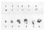
1つの態様において、本明細書内の教示に従って説明されるサンプリングデバイスの例示的な実施形態のうちの少なくとも1つでは、FNAと比較した場合により大きな試料体積が標的部位から抽出され得る。加えて、導管の先端は、標的部位から試料を得るときに特定の機械的変位信号を使用することによって、より優れた精度および正確性で制御され得る。この増大された制御およびより大きなサンプリング体積が、より小さい導管先端の使用をもたらし得る。増大された制御は、FNAが操作者によるかなり主観的な手の動きを必要とする一方、本明細書に説明される実施形態によって表される技術は必ずしも主観的な手の動きを必要としないため、FNAと比較した場合に、例えば試料体積において、ユーザ間またはユーザ内のより小さい変動性として現れ得る。ユーザ内の変動性における向上の例は、図6Bに提示されるデータによって実証される。したがって、手術環境の外、例えば、一般医の診療室内で、非侵襲的手技において使用され得るサンプリングデバイスの少なくとも1つの実施形態が存在する。 In one embodiment, in at least one of the exemplary embodiments of the sampling device described according to the teachings herein, a larger sample volume can be extracted from the target site when compared to FNA. In addition, the tip of the conduit can be controlled with better accuracy and accuracy by using a specific mechanical displacement signal when obtaining the sample from the target site. This increased control and larger sampling volume can result in the use of smaller conduit tips. The increased control requires the FNA to have fairly subjective hand movements by the operator, while the techniques described by the embodiments described herein do not necessarily require subjective hand movements. Thus, when compared to FNA, it may manifest itself as less variability between and within users, for example in sample volume. An example of an improvement in variability within a user is demonstrated by the data presented in FIG. 6B. Thus, there is at least one embodiment of a sampling device that can be used in non-invasive procedures outside the surgical environment, eg, in the clinic of a general practitioner.
機械的変位信号または変位信号という用語は、変位源によって生成され、かつ、標的部位からのサンプリングまたは標的部位への実体物の送達など、導管の端において特定の作用を実施するために、導管に沿ってその外表面および/または内表面を介して導管の端まで伝送するために導管に結合される信号を指すことに留意されたい。変位信号の例としては、限定されるものではないが、音響波、機械的波、または負荷応力に起因するひずみが挙げられる。音響波は、超音波周波数を含む様々な周波数のものであり得る。変位信号および機械的変位信号という用語は、互いに等価である。加えて、音および超音波は、音響波の例である。さらには、音響波または機械的波モードは、共鳴モードであり得ることに留意されたい。例えば、波、圧力、応力、強度、エネルギー、またはモードに対して適用される「音響または機械的」という修飾語句は、導管の動きが、i.音響波もしくは機械的波、ii.音響波および機械的波、またはiii.ひずみに起因し得ることから本明細書内で使用される。 The term mechanical displacement signal or displacement signal is generated by a displacement source and is used on the conduit to perform certain actions at the end of the conduit, such as sampling from the target site or delivery of an entity to the target site. Note that it refers to the signal coupled to the conduit for transmission along its outer and / or inner surface to the end of the conduit. Examples of displacement signals include, but are not limited to, acoustic waves, mechanical waves, or strains due to load stress. Acoustic waves can be of various frequencies, including ultrasonic frequencies. The terms displacement signal and mechanical displacement signal are equivalent to each other. In addition, sound and ultrasound are examples of acoustic waves. Furthermore, it should be noted that the acoustic or mechanical wave mode can be a resonance mode. For example, the modifier "acoustic or mechanical" applied to a wave, pressure, stress, intensity, energy, or mode is that the movement of the conduit is i. Acoustic or mechanical waves, ii. Acoustic and mechanical waves, or iii. As used herein, it can be due to strain.
別の態様において、本明細書内の教示に従って説明されるサンプリングデバイスの少なくとも1つの実施形態は、細胞、組織、および生検部位などの標的部位の外側の他の領域への外傷および損傷を最小限にするように、ならびに抽出された試料の量および種類を制御するように構成され得る。例えば、導管に沿って伝播する音響波または機械的波は、強度が極めて低くなるように制御され得る(例えば<1W/cm2)。したがって、音響波または機械的波は、特に、組織試料を得るために使用される導管が非常に長く、患者の身体内の感覚器官に隣接して位置する必要があり得ることが理由で、生きた人間または動物に対して使用する際には患者安全性のために重要である、導管を取り囲む環境を邪魔したりそれに損傷を与えたりしない。しかしながら、音響波または機械的波エネルギーが導管の先端における収束斜面を伝播するときには、音響波または機械的波エネルギーは、導管内の同じ出力がより小さい断面積内に集中されるために、幾何的に大いに増幅され得る。したがって、高強度(>1W/cm2)および高変位(>1μm)運動が、導管の最先端において達成され得る。この強度および運動は、細胞/組織の構成物/コアを切断/掻爬するのに十分な強さである。したがって、サンプリングデバイスの音響/機械的構造は、1)構造単純性を有し、2)製造が容易であり、3)低費用、および、4)より大きな作動は試料が取られる必要のある導管先端でのみ発生する必要があるため、増大された患者安全性を有する。組織試料獲得の場合、これは、サンプリングデバイスの導管先端が、所望の場合には、従来型のFNAのようにあちこち動かされる必要がないことから、大きな空間的正確性も提供する。 In another embodiment, at least one embodiment of the sampling device described according to the teachings herein minimizes trauma and damage to other areas outside the target site such as cells, tissues, and biopsy sites. It can be configured to limit and control the amount and type of sample extracted. For example, acoustic or mechanical waves propagating along a conduit can be controlled to be extremely low in intensity (eg <1 W / cm 2 ). Therefore, acoustic or mechanical waves live, especially because the ducts used to obtain tissue samples are very long and may need to be located adjacent to the sensory organs within the patient's body. It does not interfere with or damage the environment surrounding the duct, which is important for patient safety when used against humans or animals. However, when acoustic or mechanical wave energy propagates on a convergent slope at the tip of the conduit, the acoustic or mechanical wave energy is geometric because the same output in the conduit is concentrated in a smaller cross-sectional area. Can be greatly amplified. Therefore, high intensity (> 1 W / cm 2 ) and high displacement (> 1 μm) motion can be achieved at the tip of the conduit. This intensity and movement is strong enough to cut / cure cell / tissue constituents / cores. Therefore, the acoustic / mechanical structure of the sampling device is 1) structural simplicity, 2) easy to manufacture, 3) low cost, and 4) a conduit in which a sample needs to be taken for greater operation. It has increased patient safety because it only needs to occur at the tip. In the case of tissue sample acquisition, it also provides great spatial accuracy because the conduit tip of the sampling device does not need to be moved around like a conventional FNA if desired.
本明細書に説明される様々なサンプリングデバイスが適用される標的部位は、目標物の部分であることに留意されたい。目標物は、人間および動物を含む、生きているまたは死んでいる植物相または動物相であり得る。人間または動物は、患者または試験対象であり得る。他の場合において、目標物は、限定されるものではないが、例えば、ポリマー、ナノ材料、生体材料、ナノ複合材料、セラミック、透析膜、高粘性流体、織物、または製紙パルプなどの工学材料であってもよい。さらに他の場合において、目標物は、限定されるものではないが、例えば、チーズなどの乳製品、肉製品、魚製品、および野菜製品などの食品であってもよい。さらに他の場合において、目標物は、限定されるものではないが、例えば、粘土、土、および砂岩などの天然材料であってもよい。 It should be noted that the target site to which the various sampling devices described herein are applied is part of the target. The target can be a living or dead flora or fauna, including humans and animals. A human or animal can be a patient or subject to study. In other cases, the target is, but is not limited to, in engineering materials such as, for example, polymers, nanomaterials, biomaterials, nanocomposites, ceramics, dialysis membranes, highly viscous fluids, textiles, or paper pulp. There may be. In yet other cases, the target may be, but is not limited to, food products such as dairy products such as cheese, meat products, fish products, and vegetable products. In yet other cases, the target may be, but is not limited to, natural materials such as clay, soil, and sandstone.
本明細書内の教示に従って説明されるサンプリングデバイスの少なくとも1つの例示的な実施形態の潜在的な用途は、限定されるものではないが、例えば、組織学、体外診断、骨髄抽出、骨抽出、細胞学、組織のイメージングおよびマイクロイメージング、組織工学、薬物送達(特に局所的な)、ならびにマイクロ組織刺激のうちの少なくとも1つを含み得る。マイクロ組織刺激の場合、特定のUS周波数および事実上US「針術」を実施する他の特性を使用することによって、局所組織を刺激または下方制御するためにUSが使用され得る。別の実施形態は、瞬間的/可逆的または永久的/不可逆的な様式で、形状、浸透性などの性質を変化させるために本明細書内の教示に従って刺激され得るミクロまたはナノ構造の材料を伴い得る。 Potential use of at least one exemplary embodiment of the sampling device described according to the teachings herein is, but is not limited to, eg, histology, in vitro diagnosis, bone marrow extraction, bone extraction, and the like. It may include at least one of cytology, tissue imaging and microimaging, histology, drug delivery (especially topical), and microtissue stimulation. In the case of microtissue stimulation, US may be used to stimulate or downregulate local tissue by using specific US frequencies and other properties that effectively perform US "acupuncture". Another embodiment is a micro or nanostructured material that can be stimulated according to the teachings herein to change properties such as shape, permeability, etc. in a momentary / reversible or permanent / irreversible manner. Can accompany.
本明細書内の教示に従って説明されるサンプリングデバイスの少なくとも1つの実施形態において、変位信号源から発せられる、少なくとも1つの周波数を有する変位信号、例えば機械的波、音響波、または負荷応力に起因するひずみ(例えば、圧縮、伸張、せん断、またはねじれ)は、針などの導管への入力信号として結合され、導管を通ってまたは導管に沿って、導管の遠位端部分、例えば針端/先端に向けて伝送される。少なくともいくつかの場合において、針は、皮下注射針であってもよい。導管の遠位端は、実体物獲得中に標的部位を貫通し作動させるための穿刺構造体を有する。導管端部分の幾何学的形状は、そこに伝送される変位信号を増幅および改変するようにテーパ付きであってもよい。したがって、高い圧力/変位振幅ならびに既定の先端軌道が、導管端部分において達成され得る。機械的波または音響波の導管への結合に応じて、機械的波または音響波モードに従う機械的波または音響波は、導管および/または導管端部分内をまたはそれに沿って伝播し、限定されるものではないが、例えば、縦波、せん断波、屈曲波、ラム波、疑似ラム波、スフォルテ波、ストンレー波、ラブ波、レーリー波、フランツ波、またはねじれ波のうちの少なくとも1つであり得る。これらの波は、進行波または定常波であり得、好ましくは、屈曲波または縦波であり得る。例えば、単一カプラまたは同じ導管に接続される多数のカプラのサイズおよび形状は、導管の先端および端部分における特定の所望の作用に有益である導管内の音響波または機械的波モードを生成するために使用され得る。入力変位信号は、線形または非線形方式で伝播する、一定もしくは動的に変化する振幅、または一定もしくは動的に変化する周波数、または一定または動的に変化する位相を有する連続波、パルス、またはバーストであってもよい。ある実施形態が、超音波である、すなわち、20kHzを超える音響波を使用するとき、この実施形態は、「超音波強化された微細針吸引」、すなわちUSeFNAと呼ばれ得る。 In at least one embodiment of the sampling device described according to the teachings herein, due to a displacement signal having at least one frequency, such as a mechanical wave, an acoustic wave, or a load stress, emanating from a displacement signal source. Strain (eg, compression, extension, shear, or twist) is coupled as an input signal to a conduit such as a needle and through or along the conduit to the distal end portion of the conduit, such as the needle end / tip. Is transmitted toward. In at least some cases, the needle may be a hypodermic needle. The distal end of the conduit has a puncture structure to penetrate and actuate the target site during substance acquisition. The geometry of the conduit end portion may be tapered to amplify and modify the displacement signal transmitted therein. Therefore, high pressure / displacement amplitudes as well as predetermined tip trajectories can be achieved at the conduit end portions. Depending on the coupling of the mechanical or acoustic wave to the conduit, the mechanical or acoustic wave according to the mechanical or acoustic wave mode propagates and is limited within or along the conduit and / or the end of the conduit. Although not, it can be, for example, at least one of a longitudinal wave, a shear wave, a bending wave, a ram wave, a pseudo-ram wave, a Sforte wave, a Stonley wave, a Love wave, a Rayleigh wave, a Franz wave, or a twisted wave. .. These waves can be progressive or standing waves, preferably bending or longitudinal waves. For example, the size and shape of a single coupler or multiple couplers connected to the same conduit produces an acoustic or mechanical wave mode within the conduit that is beneficial for a particular desired action at the tip and end of the conduit. Can be used for. The input displacement signal is a continuous wave, pulse, or burst that propagates linearly or non-linearly with a constant or dynamically changing amplitude, a constant or dynamically changing frequency, or a constant or dynamically changing phase. May be. When an embodiment is ultrasonic, i.e. using acoustic waves above 20 kHz, this embodiment may be referred to as "ultrasonic enhanced fine needle suction", i.e. USeFNA.
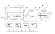
これより図1Aを参照すると、そこに示されているのは、本明細書内の教示に従うサンプリングデバイス10の例示的な実施形態である。サンプリングデバイス10は、制御ユニット12、変位信号源14、結合組立体16、圧力制御器18、リザーバ20、ハウジング22、および導管端部分25を有する導管24を備える。ハウジング22は、手術中に医療従事者などのユーザによって保持され得るサンプリングデバイス10の把持領域を提供する。ハウジング22はまた、サンプリングデバイス10のいくつかの内部構成要素を保護し、また、サンプリングデバイス10の特定の構成要素の機械的接続のためのプラットフォームを提供する。ユーザは、以下により詳細に説明されるように、標的部位から解剖学的試料を得るため、および/または物質を標的部位に提供するためにサンプリングデバイス10を使用し得る。標的部位は、患者、動物、死亡した個人、または目標物、または物質に対応し得る。
Referring further to FIG. 1A, what is shown therein is an exemplary embodiment of the
制御ユニット12は、制御インターフェース28、制御器30、信号生成器32、および増幅ユニット34を備える。電気接続36a、36b、および36cは、制御ユニット12の構成要素を互いに結合する一方、電気コネクタ36dは制御ユニット12を変位信号源14に結合する。示されないが当業者には知られている電源が、制御ユニット12に電力を供給するために制御ユニット12に結合される。電源は、バッテリ、充電式バッテリ、またはAC電源に結合された変換器であり得る。電気接続36aおよび36bは、いくつかの実施形態においては、ワイヤレス接続で置き換えられ得る(例えば、電磁または音響)。
The
制御インターフェース28は、サンプリングデバイス10の動作を制御するためにユーザからの入力を受信する。制御インターフェース28は、ディスプレイ、ならびにおそらくは、マウス、キーボード、サムホイール、トラックパッド、トラックボール、フットスイッチ、運動および近接センサなどの光学または音響センサなどのうちの少なくとも1つを含むことができる。いくつかの場合において、制御インターフェース28のディスプレイは、入力手段として機能することができるタッチスクリーンであり得る。
The
制御器30は、サンプリングデバイス10の動作を制御し、当業者によって知られるような十分な処理能力を提供することができる任意の好適なプロセッサ、制御器、またはデジタル信号プロセッサ(DSP)を備え得る。例えば、制御器30は、高性能汎用プロセッサであってもよい。代替的な実施形態において、制御器30は、2つ以上のプロセッサを含んでもよく、各プロセッサは、異なる専用タスクを実施するように構成される。代替的な実施形態において、制御器30によって提供される機能のいくつかを提供するために、特定用途向け集積回路(ASIC)などの特殊ハードウェアが使用され得る。
The
信号生成器32は、後に導管24および端部分25に沿った機械的変位信号へと変換される音響波または機械的波を生成するように変位信号源14を駆動するために変位信号源14に提供される電気駆動信号を生成する。以下により詳細に説明されるが、信号生成器32は、機械的変位信号が所望の音響波または機械的波モードに従って生成されるように、駆動信号の振幅および周波数成分を制御して、導管端部分25の先端26の細かい制御を可能にすることができる。信号生成器32は、別々の電気アナログおよびデジタルコンポーネント、またはDSP、DAC、および別々の電気コンポーネントの組み合わせを使用して、デジタル-アナログ変換器(DAC)と一緒にDSPを使用して実装され得る。代替的な実施形態において、信号生成器32の機能性は、後にDACによりアナログ駆動信号へ変換される駆動信号をデジタル生成する制御器30によって提供されてもよい。
The
電力増幅ユニット34は、変位信号源14を駆動して、サンプリングデバイス10の導管24に沿った伝播のために所望の機械的変位信号を生成するのに十分な電流および電圧を有するように、信号生成器32によって提供された駆動信号を増幅させる。したがって、増幅ユニット34は、当業者によって知られるような所望の増幅を提供するために特定の回路構成に配置される演算増幅器、トランジスタ、レジスタ、インダクタ、およびコンデンサを含み得る、増幅を提供するためのアナログ回路を含む。
The
制御ユニット12は、サンプリングデバイス10の部分であるように実装されてもよく、携帯式であってもよい。代替的に、他の実施形態において、制御ユニット12は、デスクトップコンピュータ、ラップトップ、タブレットコンピュータ、モバイル通信デバイス、ヘッドセットなどのコンピューティングデバイスによって提供されてもよい。
The
例示的な実施形態において、機械的変位源、音響波源、またはひずみ源とも呼ばれ得る変位信号源14は、変位信号源14が超音波放射トランスデューサ(例えば圧電性トランスデューサ)ならびに圧電性トランスデューサによって生成された音を増幅するための少なくとも1つの音響共鳴器および/またはホーンを備えることを意味するランジュバントランスデューサである。代替的に、他の実施形態において、変位信号源14は、可撓緊張性圧電アクチュエータであり得る。他の実施形態において、変位信号源14は、圧電(例えば、平坦なもしくは集中的な要素または振動子アレイ)、電気スパークギャップ、火工スパーク、光誘起されたプラズマスパーク、CMUT(容量性超微細加工超音波トランスデューサ)、PMUT(圧電性超微細加工超音波トランスデューサ)、IDT(インターデジタルトランスデューサ)、RF源(電気ひずみ、磁気ひずみ、または誘導に基づく)、可撓緊張性トランスデューサ、モータ、または任意の他の等価の音響波源もしくは機械的波源もしくはひずみ源のうちの少なくとも1つを含む。そのような場合において、電力増幅ユニット34および信号生成器32は、使用される特定の機械的変位源を駆動するために特別に最適化されたユニットと置き換えられ得る。
In an exemplary embodiment, the
変位信号源14によって生成される機械的エネルギーは、約0.1Hz~100MHz、およびより好ましくは、約10~200kHzの範囲内の主たる周波数(例えば正弦)または複数の周波数(例えば広帯域)を有することができる。例えば、熱または音響放射力効果を達成するため、約200kHz~20MHzのより高い周波数が使用されてもよい。生成された音響波または機械的波の瞬間的強度または時間平均強度は、約1mW/cm2~10kW/cm2の範囲内、およびより好ましくは、約0.1~100W/cm2の範囲内であり得る。生成された機械的エネルギーは、パルス、バースト、または連続波を含み得、圧力、密度、変位、および粒子速度などのパラメータ間の時間的な関係は、線形または非線形であり得る。生成された音響波の包絡線、周波数成分、および振幅は、任意の知られているまたは恣意的な関数によって時間的または空間的に変調され得る。例えば、変調は、「脈動する」放射力を達成するために使用され得る。
The mechanical energy produced by the
いくつかの実施形態において、変位信号源14は、音響波または機械的波モード制御を使用して、サンプリングデバイス10の特定の用途に有益である導管先端26および導管端部分25における所望の作用を達成するために、多数のトランスデューサタイプまたは導管24に対して異なる配向角度を有する多数のトランスデューサを備え得る。音響波または機械的波モード制御は、本明細書内の図4A~図4Gに関連してさらに論じられる。
In some embodiments, the
結合組立体16は、音響/機械カプラ38および40、導波管42、ならびに収束構造体44を備える。音響/機械カプラ38および40は、導波管42の第1の端を変位信号源14に、および導波管42の第2の端を導管24に結合するために使用される音響インピーダンス整合要素である。音響/機械カプラ38および40は、変位信号源と導管24との間の電気的分離を提供し、それにより向上された電気保安を提供する材料からできていてもよい。限定されるものではないが、例えば、ねじ、迅速ロック、もしくはねじ山、または粘着手段(例えば、のり、イオンまたは共有結合)など、異なる手段または留め具が、音響/機械カプラ38および40を導波管42の両端に装着するために使用され得る。音響/機械カプラ38および40、導管24、ならびに変位信号源14の音響および機械インピーダンスは、1つの要素から別の要素への波の省エネルギー伝送のため、および導波管42への音響/機械結合のために類似し得る。
The
導波管42の長さおよび形状は、サンプリングデバイス10の特定の用途に有益である導管先端26および導管端部分25における所望の作用(例えば、所望の量および/または種類の機械的変位)を生成するために、導波管42内で共鳴を誘起するために実際に使用される所望の音響/機械的波モードと一致し得る。共鳴は、次元における長さが、その次元に沿って伝播する波長の一部分に比例する構造において達成され得る。例えば、直線導波管では、所望の共鳴は、「半開きの」導波管の長さがn×1/4×音響波または機械的波の波長であるときに達成され得、式中、nは正整数である。材料選択は、所望の音響波または機械的波モードの音響波または機械的波の速度に影響を与える。導波管42のサイズおよび形状は、導波管42のある特定の場所における変位を増幅させるために使用され得る。テーパ付き構造もまた、変位を増幅させるために使用され得る。
The length and shape of the
導波管42は、細胞を効率的にほぐし取る一方で、随意に、これらの細胞の相対的順序、構造、および機能を保存し、例えば周辺組織など標的部位の周辺領域への過度な損傷を発生させないために、導管24の端部分25および先端26における意図された変位の幾何学的な増幅および制御を達成するために選択され得る任意のサイズ、形状、および材料のものであり得る。そのような実施形態の例は、図1Aに提示される。
The
導波管42の機械または音響インピーダンスは、好ましくは、音響/機械カプラ38および40ならびに/または変位信号源14のものに近い。これは、変位信号源14から音響/機械カプラ38および40への機械的波または音響波の効率的な転送を達成するため、および潜在的には、定常波が望ましくないときには導管24内の定常波を回避または低減するためである。しかしながら、本明細書内の教示に従う実施形態のうちの少なくともいくつかにおいて、変位の最大ダイナミックレンジに対して導管先端26の大きい変位を達成するためには意図された音響波または機械的波モードの定常波を利用することが望ましい場合がある。一部の実施形態においては、導波管42全体が体外にあるが、一部の実施形態においては、導波管42は、標的部位が位置する目標物内にあり得る。
The mechanical or acoustic impedance of the
変位信号源14がホット電極を含む実施形態では、導管24は、患者に電気ショックを与えることがないようにホット電極から電気的に絶縁される必要がある。しかしながら、電気作動、例えば、組織のRFアブレーションまたは焼灼が意図される実施形態では、電流が導管24へと流れそれを通して標的部位へと流され得る。この場合、導管24に平行するか、または導管24の近くの、電気的に接地された電極または接地された別個の針が、標的部位内への電流の漏出を回避するため、または標的部位が患者もしくは動物などの生き物の部分であるときには標的部位へ電気ショックを与えることがないように、使用され得る。導管24の露出領域、および使用され得る任意の追加の針は、安全性向上のために電気絶縁材料で被覆されてもよい。
In embodiments where the
導波管42と一体であり得る任意選択の収束構造体44は、導波管42から受容されるエネルギーへの幾何学的な増幅の第1のステージを提供し、増幅された波エネルギーを導管先端26へ向けて伝播する。増幅は、例えば、典型的には>1kHzの周波数では屈曲または縦モードで提供される。増幅された機械的波または音響波が導管先端26に到達すると、波のエネルギー、したがって導管24の構造内の機械的波または音響波エネルギーと関連付けられた粒子(例えば分子)変位もまた、導管先端26の端において収束構造体26bによって提供される幾何学的な増幅の第2のステージを経る。この実施形態では、導管24の管状側26aは、機械的波または音響波エネルギーにさらなる増幅を提供する収束構造体26b、ならびに使用中に標的部位に提供される音響波または機械的波エネルギーに起因して標的部位において変位される試料細胞を受容するためのチャネル26cとして斜面を提供する。
The optional
導管24は、限定されるものではないが、例えば、ステンレス鋼、真ちゅう、ニチノール、MRI適合性金属、シリコン、ポリマー、またはセラミックなどの様々な医療用材料製であり得る。導管24はまた、限定されるものではないが、例えば、ニッケルめっき、PTFE、パリレン、セラミック、窒化シリコン、金、炭素、ダイヤモンド、または薬物などの様々な材料を使用して被覆されてもよい。代替的に、いくつかの実施形態において、導管24は、非被覆であってもよい。導管24のトポロジは、デバイス10の特定の用途に応じて選択され得る。この例示的な実施形態において、導管24は、中空チャネル26c、ならびに斜面を形成するための角度付けされた壁26aおよび26bを含む。
The
1つの例示的な実施形態において、導管24は、被覆されたまたは非被覆のステンレス鋼製であり、かつ少なくとも150μmである針外径、および好ましくは寸法規格14~34(すなわち、公称外径0.184~2.11mm)を有する、使い捨て皮下注射針であり得る。皮下注射針は、1つまたは複数のコアを有し得る。ダブルコアが存在する実施形態では、一方のコアは、薬剤または実体物を標的部位に送達するために使用され得、第2のコアは、標的部位から実体物または試料を抽出するために使用され得る。薬剤は、薬物または細胞または他の物質であり得る。他の実施形態においては、他の種類の針が使用され得る。
In one exemplary embodiment, the
少なくとも1つの実施形態において、導管24の外表面および/または内表面は、限定されるものではないが、例えば、所望の場合には細胞のより良好な保存、または細胞抽出手技中により多くの細胞を切り離すためなどの様々な目的のために、(i)防腐性表面、(ii)試料抽出の向上、(iii)キャビテーション核形成部位、または(iv)導管24と標的部位における細胞との間ならびに導管24と抽出された試料との間の改変された相互作用のうちの少なくとも1つを提供するために被覆またはパターン化され得る。いくつかの実施形態において、導管24の端部分25の内表面および/もしくは外表面または導管24の外表面もしくは内表面において使用されるパターン内にエアポケットを作成することまたはトラップすることにより、伝播する機械的ソリトンまたは空間的に制御されたキャビテーションを生成することによって、より多くの細胞が切り離され得る。より具体的には、導管の内表面または外表面は、使用中に核形成部位を提供するために溝、穴、くぼみ、およびパターンのうちの少なくとも1つを含み得る。いくつかの実施形態において、細胞(組織細胞または他の物質の細胞など)が、特定のサイズおよび特定の性質を有する細胞成分を得るために制御された様式で崩壊され得るように、細胞は抽出され得、標的部位からの抽出後に、その細胞に対して異なる用途が適用され得る。
In at least one embodiment, the outer and / or inner surface of the
本明細書内の教示の1つの態様において、導管24と標的部位における組織との間および/または導管24と抽出された試料との間の改変された相互作用は、導管の内表面、導管24の外表面、および/または斜めの端部分25に対して異なる形状を使用し、特定の音響波または機械的波を生成するように変位信号源24を構成することによって達成され得る。例えば、本明細書内の教示に従う少なくとも1つの例示的な実施形態において、導管24の外表面および変位信号源14は、標的部位における導管24の挿入/抽出中の摩擦を低減し、「音の潤滑油」としての役割を果たすため、すなわち音響波または機械的波による摩擦の非化学的低減、ならびに吸引中に吸い込まれた試料細胞を無傷のままにするために使用され得る、表面波(漏れ波としても知られる)を導管24の外表面上に生成するように適合され得る。
In one aspect of the teachings herein, the modified interaction between the
本明細書内の教示に従う別の態様において、斜面形状は、導管24の端部分25において所望の音響波もしくは機械的波モードまたは試料抽出機序を制御または修正または増幅するように設計され得る。様々な形状を有する異なる導管端部分および斜面についての例示的な実施形態は、図1B~図1Gおよび図1M(側面図)ならびに図1H~図1K(上面図)に示される。
In another embodiment according to the teachings herein, the slope shape may be designed to control, modify or amplify the desired acoustic or mechanical wave mode or sampling mechanism at the
例えば、図1Bは、外表面に鋸歯パターン54のある管状壁52と平坦な斜面端部分56とを有する導管50を示す。鋸歯パターン54は、導管50の外周の周りに延在するが、導管50の管状壁52の一部分が取り除かれているため、鋸歯パターン54はテーパ付き部分54’を有するということを理解されたい。図1Cに示される代替的な実施形態において、導管60は、内表面に鋸歯パターン64のある管状壁62と平坦な斜面端部分66とを有し得る。鋸歯パターン64は、導管60の内周の周りに延在し、テーパ付き部分64’を有する。
For example, FIG. 1B shows a
これより図1Dを参照すると、そこに示されているのは、長い壁72から短い壁72’に遷移するようにテーパ付けされる管状壁を有する導管70の代替的な実施形態であり、壁72および壁72’それぞれの端部分74および74’は、例えば、針斜面上の凹領域と標的部位との間に比べて、針斜面上の凸領域と標的部位との間におけるより高いプリストレスなど、異なる量の力を標的部位に印加するゾーンを達成するために、斜面76が波状または正弦プロファイルを有するように湾曲される。
Referring further to FIG. 1D, what is shown therein is an alternative embodiment of a
これより図1Eを参照すると、そこに示されているのは、長い壁84から短い壁84’に遷移するようにテーパ付けされる開口部を有する管状構造を有する導管80の代替的な実施形態であり、壁の端部分は、斜面86が単一または複数の隣接する準凹形または指数関数的に収束するプロファイルを有するように湾曲される。この構造が、斜面86の近位端と比べて斜面86の遠位端において非常に高い変位振幅が達成されることを可能にする。代替的な実施形態において、壁84の端部分は、斜面86が完全な凹形プロファイルまたは異なる半径の湾曲を有することができるように形状付けされ得る。
Referring further to FIG. 1E, there is an alternative embodiment of a
これより図1Fを参照すると、そこに示されているのは、長い壁94から短い壁94’に遷移するようにテーパ付けされる管状壁を有する導管90の代替的な実施形態であり、壁の端部分は、斜面96が、階段状、粒状、または鋸歯プロファイルを有するように形状付けされる。この構造は、斜面運動の前およびその最中の高い応力により標的部位との複数の接触点または応力点(例えば、2mm2の表面積を有する1つの斜面においては3~109個)を達成する。3つの応力点を有する斜面は、階段状または鋸歯プロファイルに相当し得る一方、およそ1,000個の応力点を有する斜面は、粒状プロファイルまたはマイクロラフネスプロファイルに相当し得、およそ109個の応力点を有する斜面は、ナノラフネスプロファイルに相当し得る。
Referring further to FIG. 1F, which is shown therein is an alternative embodiment of a
これより図1Gを参照すると、そこに示されているのは、大きなスパイク形状を有する上方部分104および下方部分104’を有するようにギザギザになっている管状壁102を有し、その結果、斜面106が複数先端になっている、導管100の代替的な実施形態である。この構造は、高い材料変位振幅により斜面端における複数の作動点を達成する。
Referring further to FIG. 1G, what is shown there is a
これより図1Hを参照すると、そこに示されているのは、斜面が収束構造体でありかつ円すい形状プロファイルを有するように内向きにテーパ付けされる端部分114を有する管状壁112を有する導管110の代替的な実施形態である。この構造は、導管110の開口部116の付近における作動を可能にする。
Referring further to FIG. 1H, what is shown therein is a conduit having a
これより図1Iを参照すると、そこに示されているのは、端部分126が平坦な縁の付いた角状またはじょうご形状プロファイルを有するように、外向きに広がっているか、または分岐している側壁付きの端部分124を有する管状壁122を有する導管120の代替的な実施形態である。分岐構造は、斜面端において大きな変位を得るために(例えば図1Hに提示されるものと類似して)別の視野角から観察されるときには同時に収束している場合があるが、標的部位と斜面との間に大きな接触面積を有する。これは、例えば、血管および神経などの線状組織構造から試料を得るために使用され得る。
Referring further to FIG. 1I, it is shown that the
これより図1Jを参照すると、そこに示されているのは、斜面136が三角形またはV字形状プロファイルを有するように端部分に切り込み134を有する管状壁132を有する導管130の代替的な実施形態である。これは、例えば、導管斜面の外縁上のすべての点において大きな変位を均一に達成するために使用され得る。
Referring further to FIG. 1J, it is shown in an alternative embodiment of a
これより図1Kを参照すると、そこに示されているのは、中実部分142および様々な開口部のある通気部分143を有する管状壁と、斜面146のための円すい形状を有する収束構造体を形成するために内向きにテーパ付けされる壁を有する端部分144とを有する導管140の代替的な実施形態である。この構造は、導管端部分または斜面の付近における複数の点からの導管140の内側部分への標的部位からの物質の流入を可能にする。代替的な実施形態において、通気部分143は、格子状パターンもしくはらせん状パターンなどの異なるパターンの開口部、1つ、2つ、3つ、またはそれ以上などの異なる数の開口部を有し得る。
Referring further to FIG. 1K, it shows a tubular wall with a
これより図1Lを参照すると、そこに示されているのは、長い壁146から短い壁146’に遷移するようにテーパ付けされる管状壁を有する導管145の代替的な実施形態である。導管145の先端は、線状または直線である縁147’および148(領域Aによって識別される)を有する一方、縁147は、それぞれ領域BおよびCによって識別される凹様部分および直線部分を有する。したがって、導管145は、複数の先端セグメントA、B、およびCを有する階段状斜面を有すると説明されてもよい。この斜面は、先端領域B近くでは比較的薄い管壁を有し、急速に収束しないが、例えば、図1Eの斜面と比べると、セグメントCでは急速に収束する。これは、針先端近く(領域BおよびC)に比較的高い振幅の運動をもたらすが、潜在的には、図1Eの斜面などの他の非常に薄い斜面端よりも耐久性がある(すなわち、それほど容易に破損しない)。導管145は、例えば、針斜面上の凹様領域(すなわち、セクションA、B、またはCの中心部)と標的部位との間と比べて、針斜面上の凸様領域(すなわち、セクションAとBもしくはセクションBとCとの間の境界近くまたは針終端近く)と標的部位との間におけるより高いプリストレスなど、異なる量の力を標的部位に印加するゾーンを有するプロファイルを有するものと見なされ得る。
Referring further to FIG. 1L, what is shown therein is an alternative embodiment of a
異なる導管実施形態の端部分および斜面の様々な形状は、細胞種類、細胞サイズ、細胞形状、細胞配向、細胞病理、細胞数、細胞種類、または細胞の任意の他の性質もしくは埋め込み構造および材料の任意の性質のうちの1つまたは複数によって選択的に細胞を切り離すために使用され得る。これは、斜面幾何学的形状が導管および斜面の異なる部分における変位を変化させることが予期されるため、異なる斜面幾何学的形状が異なる種類の作動をもたらすことが予期されることから達成され得る。さらには、異なる組織は、USeFNAに対して異なって反応する(発明者らによって発見されたように)。したがって、試料の質は、斜面の性質に応じて異なり得ることが予期される。 The various shapes of the ends and slopes of the different conduit embodiments are of cell type, cell size, cell shape, cell orientation, cytopathology, cell number, cell type, or any other property or implant structure and material of the cell. It can be used to selectively isolate cells by one or more of any property. This can be achieved from the fact that different slope geometries are expected to result in different types of operation, as slope geometries are expected to change displacements in conduits and different parts of the slope. .. Moreover, different tissues react differently to USeFNA (as discovered by the inventors). Therefore, it is expected that the quality of the sample may vary depending on the nature of the slope.
一般に、導管端部分25の斜面は、約0.1~180°(0.1°は非常に鋭い先端に相当し、180°は終端が平坦な先端に相当する)に及び得る平均開口角度を有し得、好ましくは、約5~45°の範囲内にあり得る。平均開口という用語が使用されるのは、角度が、階段状もしくは鋸歯様の斜面またはラフネスのある斜面については規定するのは困難であり得るが、導管の先端において収束する導管の壁縁によって規定される角度であると見なされ得るためである。図1B~図1Lに示されるように、斜面形状は、大半の実施形態については収束性であり、特定の割合で直線的または指数関数的に収束している場合がある。斜面形状は、知られている関数または任意関数によって表現され得る幾何学的形状を有し得る。
In general, the slope of the
さらに、斜面の形状に応じて、いくつかの実施形態では、導管24の圧力および変位振幅は、斜面の開口角度が小さいときには特に、先端26において、特に26bにおいて、または、導管24の端部分25、およびより具体的には、針斜面構造体26bの稜角もしくは縁において、最も大きい。
Further, depending on the shape of the slope, in some embodiments, the pressure and displacement amplitude of the
さらに、別の態様において、本明細書内の教示に従って説明される少なくとも1つの実施形態では、使用中の導管先端26の運動は、限定されるものではないが、例えば、切断力、断裂力、把握力、つまみ取る力、圧縮力、伸張力、せん断力、屈曲力、ぜん動力、およびねじり力など、標的部位において異なる種類の力または作用を及ぼすように制御される場合と制御されない場合がある。加えて、これらの力の大きさは、特定の音響波または機械的波を生成するように変位信号源14を構成することによって、ならびに十分な力および/または応力が標的部位において印加されて、目標物、例えば、標的部位における所望の細胞構成物、限定されるものではないが、細胞、細胞の群、細胞のクラスタ、もしくは線維などの細胞外組織マトリックス、または特定の目標物の組織片もしくは軟/硬組織コアなどを切り離すように、導管端部分25について特定の形状を有することによって、制御され得る。組織片は、例えば、病理(例えば、肉腫、腫瘍、または任意の他の組織病変)、組織(例えば、乳房、甲状腺、前立腺、関節軟骨、線維軟骨、腱、靱帯、肝臓、膵臓、脳、神経、目、筋肉、膀胱、腎臓、心臓、骨髄などの軟組織;皮膚、胃腸(例えば、口腔、咽頭、食道、胃小腸、大腸、胆嚢、胆管)などの内層組織および粘膜;呼吸(例えば、肺、喉頭、気管支、小気道);泌尿(例えば、尿管、膀胱、尿道);女性生殖系[子宮内膜、頸部、膣])、および硬組織(例えば、緻密骨、多孔質骨、軟骨下骨、または他の石灰化組織)のうちの1つまたは複数を含み得るが、これらに限定されない。実際には、針終端近くの標的部位内の圧縮力、伸張力、せん断力、およびねじり力は、変位信号源14が、導波管42の収束構造体44近くに屈曲または縦運動を生成する縦波をもたらし、導管24内の屈曲または縦の定常波運動を達成して斜面26bにおける高振幅の変位運動を達成する超音波サンドイッチトランスデューサを備える場合に達成され得る。変位の大きさは、一般に、>1μmであり、いくつかの用途では、好ましくは>10μmである。いくつかの状況において、例えば、導管24の低い基本共鳴周波数では、変位の大きさは、屈曲運動中には、例えば>1mmであり得る。
Moreover, in another embodiment, in at least one embodiment described according to the teachings herein, the movement of the
再び図1Aを参照すると、導管24は、例えば、圧力制御器18へのアルミニウムまたはポリプロピレンハブであり得るコネクタ45によってサンプリングデバイス10に接続されてもよい。コネクタ45は、標的部位から導管24を通って圧力制御器18へと向かう試料の流れ、または導管24および次いで標的部位への薬物の流れを可能にするために開口部を有する。圧力制御器18は、試料を得るために導管24を通じて低圧(すなわち、吸引圧力)を印加するように、または薬物もしくは他の実体物を標的部位に送達するために高圧(すなわち、送達圧力)を導管24に印加するように動作され得る圧力アクチュエータ46を備える。
Referring again to FIG. 1A, the
少なくとも1つの例示的な実施形態において、圧力制御器18は、アクチュエータ46として動作するピストン付きの従来型の注射器を使用して実装され得る。ピストンは、導管24に向かって押すか、または導管24から離れる方へピストンを引くかのいずれかによってユーザがピストンを操作することを可能にするためにハンドル47を備える。ピストンはまた、リザーバ20の中身と相互作用するために使用されるヘッドまたはプランジャ48を含む。代替的な実施形態においては、ガス/水ポンプまたは圧電型ピコポンプが、ピストンの代わりに使用されてもよい。
In at least one exemplary embodiment, the
使用中、ピストンを引くことによって低圧が印加され得、それにより、導管端部分25が目標物、例えば標的組織内にあるとき、導管24の中空構造/チャネル内に、および導管端部分25および先端26の付近において、吸引を達成する。次いでこれは、標的組織部位から導管端部分25のチャネル26c内への、および潜在的には、圧力制御器18内のリザーバ20内への、切り離された組織構成物の吸引またはぜん動並進を誘発する。例示的な実施形態は、標的組織と共に使用するという観点から本明細書内では説明されるが、本実施形態と共に使用され得る他の標的目標物が存在し得ることに留意されたい。
During use, low pressure can be applied by pulling the piston, whereby when the
少なくとも1つの例示的な実施形態において、導管24またはリザーバ20は、光学センサ、電子センサ、または化学センサのうちの少なくとも1つを備え、使用されるセンサの種類に応じて、限定されるものではないが、pH、血糖、血圧、および酸素飽和度などの関連パラメータの使用中の標的部位における少なくとも1つの状態の測定値を得る。
In at least one exemplary embodiment, the
本明細書内の教示に従って、針端部分25および導管先端26の構造体によって発せられる機械的波または音響波は、標的部位が存在する目標物に応じて細胞構成物を標的部位から切り離すことに寄与する、非線形音響現象、例えば、音響流、音響放射力、およびキャビテーションを標的部位の内側に生成することができる。さらには、標的部位は、細胞抽出手技の前、最中、または後に、診断または治療目的のために、機械的波または音響波によって改変され得る。実際には、標的部位の構造は、特定のユースケースシナリオにおいては、例えば、治療または診断目的のためにそれぞれ薬物または固定剤の浸透の向上を目指して改変され得る。機械的波または音響波は、標的部位に貫通するときの長く薄い導管の摩擦または耐水圧を弱めるもしくは低減すること、または細胞の抽出を向上させることに寄与し得る。この作用は次いで、例えば感圧性細胞などの異なる種類の細胞を得るために、さらに深い部位においてさえも、微細導管/針の使用を可能にし得る。別の態様において、少なくともいくつかの実施形態では、目標物が生きている人間または動物であるときには、低下した耐貫通性は、皮膚レベルでの、または標的部位における、もしくは標的部位近くでの痛覚の低減に寄与し得る。この特徴は、限定されるものではないが、皮膚または他の組織内への、痛みを伴わないタトゥー用薬剤、例えば、薬物、造影剤、または柔軟電極など、様々な手技にとって有利であり得る。
According to the teachings herein, the mechanical or acoustic waves emitted by the structures of the
いくつかの実施形態において、図1M~図1Pおよび図1Rに示されるものなど、導管160は、2つの同心円筒162および164を備えてもよく、それらは両方とも斜めの端を有する。円筒162および164の各々は、標的部位における組織との針相互作用の向上のために、例えば、サンプリングされるべき細胞をより効率的にほぐし取るために、導管160の任意の部分、好ましくは外側円筒162の斜面が、内側円筒164とは異なる方向に一瞬だけ動くような様式で、音響波または機械的波エネルギーを別個に受容するために別個の導波管に接続される。この動きは、例えば、水平、すなわち導管160の中心縦軸に平行の方向(図1Mを参照のこと)、導管160の中心縦軸に対して垂直方向(図1Nを参照のこと)、導管160の中心縦軸に対して半径方向(図1Oを参照のこと)、またはねじり方向(図1Pを参照のこと)であり得る。
In some embodiments, the
代替的な実施形態において、単一の針170が、異なる針半体172aおよび172bにおいて異なる動きを有するために垂直に分割され得る(図1Qを参照のこと)。これは、第1および第2の針182および184を備える同心針180において使用され得、この第1および第2の針182および184は、同心であり、かつ異なる部分182aおよび182bならびに異なる部分184aおよび184bをそれぞれ有するように同様に垂直に分割され、これらは互いに対して異なって動き得る(図1Rを参照のこと)。
In an alternative embodiment, a
図1M~図1Sの導管160、170、および180の先に述べた構成は、例として提供されるものであり、針分割の数および場所、同心円筒および針先端の数、ならびに針の方向および動き(例えば、振幅、方向、音響波または機械的波モード)は、本明細書に示されるものに限定されない。さらに、いくつかの実施形態において、図1M~図1Sによって取り上げられた構成は、図1A~図1Lに示される例示的な構成と組み合わされてもよい。
The previously described configurations of
これより図2A~図2Bを参照すると、そこに示されているのは、本明細書内の教示に従う1つの例示的な実施形態における導波管250の第1の部分の、それぞれ後部斜視図および前部斜視図である。結合組立体250は、音響/機械カプラ38と結合するための第1の結合領域252、遷移領域254、ならびに音響/機械カプラ40および導管24と結合するための第2の結合領域256を備える。
Referring further to FIGS. 2A-2B, what is shown therein is a rear perspective view of the first portion of the
導波管部分250の第1の結合領域252に最も近い遷移領域254の端部分254aは、変位信号源14からの音響波または機械的波エネルギーが直線の遷移領域254により効率的に伝送され得るように、遷移領域254の縦軸および変位信号源14の縦軸とは異なる縦軸を有する(この場合は、端部分254aは湾曲されるが、他の実施形態では、湾曲されなくてもよい)。同様に、第2の結合領域256に最も近い遷移領域254の端部分254bもまた、音響波または機械的波を遷移領域254から第2の結合領域256へ誘導するために、遷移領域254の縦軸とは異なる縦軸を有する(この場合、端部分254bは湾曲されるが、他の実施形態では、湾曲されなくてもよい)。いくつかの実施形態において、端部分254aおよび254bは同様の湾曲を有し得ることに留意されたい。意図される場合、導波管部分250は、変位信号源14によって生成される変位信号の種類に応じて、258または258aにおいて高振幅の屈曲様(垂直)運動または縦運動を提供する。導波管部分250および260の組み合わせ(図2C~図2Dを参照のこと)は、導波管250から導管24への音響波または機械的波の省エネルギー伝送を達成するために、例えば、穴259および266を通過するねじを使用した、溝258および268内にある(組み立てられたとき)導管24の部分の周りの安定した圧縮を可能にする。
At the
この例示的な実施形態において、第2の結合領域256は、上方表面256aおよび下方表面256b、第1の端領域258aおよび第2の端領域258bを有するチャネル258、ならびにいくつかの開口部259(簡潔性のためそれらのうちの1つのみがラベル付けされている)を有するプレートのように形状付けられる。チャネル258は、導管24の下方円周部分を受容するように形状付けされる。
In this exemplary embodiment, the second
第2の結合領域の下方部分264は、導波管254から導管24へ転送される音響または波エネルギーを増幅させるために上方導波管部分260上の対応する収束部分と連携する導波管254の収束構造体の下方部分264を形成するように円すいである。問題となっている用途のために最適であるように設計されるとき、この配置は、258または258aにおいて高振幅の屈曲様(すなわち、垂直)運動(例えば、吸引物の抽出)または縦様運動(例えば、軟組織コアの抽出)を提供して、導管24内で定常屈曲波を達成する。薬物送達の場合、導管24内の波モードは、針近くの音場を変化させることが予期される。これが、音場(例えば、方向または強度分布)、したがって、薬物送達の方向および場所を変化させることを可能にし得る。
The
これより図2C~図2Dを参照すると、そこに示されているのは、1つの例示的な実施形態における第2の導波管部分260の下部斜視図および上部斜視図である。第2の導波管部分260は、上方表面262aおよび下方表面262bを有するプレートのように形状付けられた本体262を有する。第2の導波管部分260はまた、収束構造体の上方部分264、チャネル268、および開口部266(簡潔性のためそれらのうちの1つのみがラベル付けされている)を備える。
Referring further to FIGS. 2C-2D, what is shown therein is a lower perspective view and an upper perspective view of the
チャネル268は、導管24の上方円周部分を受容するようにサイズ決定される。チャネル268の縦軸は、第1の導波管部分250のチャネル258の縦軸と整列される。同様に、開口部266の場所が第1の導波管部分の開口部259の場所に対応するため、結果として、開口部259および266は、導管24がチャネル258および268内へ置かれた後に留め具を受容することができる。
収束構造体の上方部分264は、チャネル268の第1の端部分268bから収束構造体の上方部分264の中間部分264cに外向きに広がっている円すい形状を有する第1の領域264aを有する。中間部分の反対側では、収束構造体の上方部分264は第2の領域264bを有し、この第2の領域264bは、第1の領域264aと同様に形状付けられるが、第2の領域が中間部分264cからチャネル268の第2の端部分268aへ内向きにテーパが付いたテーパ付き円すい形状を有するように、配置が逆である。意図される場合、この配置は、268aにおいて高振幅の屈曲様(垂直)運動を提供して、導管24内で定常屈曲波を達成する。
The
これより図3A~図3Cを参照すると、そこに示されているのは、本明細書内の教示に従うサンプリングデバイス300のプロトタイプの一部分の例示的な実施形態の上面図、側面図、および前面図である。この例示的なプロトタイプにおいては、サンプリングデバイス300は、結合組立体316、圧力制御器318、リザーバ320、ハウジング322、ならびに導管端部分325および導管先端326を有する導管324を備える。結合組立体316は、音響カプラ338および340、導波管342、ならびに収束構造体344を備える。導管324は、例えば、圧力制御器318へのアルミニウムまたはポリプロピレンハブであり得るコネクタ345によってサンプリングデバイス300に接続される。圧力制御器318は、試料を得るために導管324を通じて低圧(典型的には、動作環境の圧力より低い、例えば<1atmまたは、目標物、例えば標的組織内より低い圧力)を印加するように、または、薬物もしくは他の実体物を標的部位に送達するために高圧(典型的には、動作環境の圧力よりも高い、例えば>1atm、または目標物、例えば標的組織内より高い圧力)を導管324に印加するように動作され得る圧力アクチュエータ346を備える。この例示的な実施形態において、圧力制御器318は、ハンドル327およびプランジャ348を備えるピストン付きの従来型の注射器である。この実施形態は、導管先端326における高振幅変位(例えば>1μm)による屈曲定常波運動の導管324への伝送と一緒に、標的部位から試料を効率的に得ることを可能にする。カプラ342の音響インピーダンスは、結合組立体316内の大きい材料変位を得るために十分に低くなければならない。ハウジング322内に包含されたトランスデューサは、信号生成器ユニットに接続された電力増幅器に接続された。
Referring further to FIGS. 3A-3C, what is shown herein is a top view, side view, and front view of an exemplary embodiment of a prototype of a
これより図3Dを参照すると、そこに示されているのは、本明細書内の教示に従うサンプリングデバイス350の別のプロトタイプの一部分の例示的な実施形態の側面図である。サンプリングデバイス350の要素のうちのいくつかは、サンプリングデバイス300のものと類似しており、同様に番号付けされる。ハウジング352は、ハウジング322と類似している。しかしながら、サンプリングデバイス350は、異なる結合組立体356を有する。結合組立体356は、「J字」形状を有する一方、デバイス300の結合組立体316は、伸張された「S字」形状を有する。結合組立体356は、第1のカプラ354と、第1の端部分357a、第2の端部分357b、遷移領域357cを有する導波管357とを備え、導波管357の中心縦軸の配向は、変位信号源からの音響波または機械的波エネルギーが導波管357の端357eから導管324に誘導され結合されるように変化する。
Referring further to FIG. 3D, what is shown therein is a side view of an exemplary embodiment of another prototype of the
導波管357は、導管324の一部分を受容するためのチャネル358、および、互いに機械的接触状態にある導波管357および導管324を堅く保持するためのねじなどの留め具359を備える。これは、導波管357の断面図を示す図3Eにより良く示される。この図では、留め具359は開位置にあり、導管324がチャネル358内に受容された後、留め具359は、閉じ位置へと締められる(留め具の上部は側面(図3Dに示されるような)からは見えなくてもよい)。いくつかの場合において、ねじは、拡大したヘッドを有しない場合がある。導波管357の端357eは、導波管357および変位信号源(図示されない)を互いに機械的接触状態に維持するカプラ354の開口部(図示されない)内に受容される。導波管357の形状は、特定の音響波または機械的波モード、例えば、導波管材料内の機械的波の形状および速度に応じて固有モードが使用中に有効にされることを可能にし得る。
The
これより図4Aを参照すると、そこに示されているのは、導管374の端部分375および先端376における変位エネルギーに対する音響波または機械的波モード制御を達成するために、変位信号源DS1、DS2、またはDS3を結合組立体CA1、CA2、またはCA3をそれぞれ介して、サンプリングデバイス370の導管374に結合する異なるやり方を示す例示的な実施形態A1である。いずれの場合においても、変位信号源DS1、DS2、またはDS3は、対応する結合組立体CA1、CA2、またはCA3へ典型的には導管374の縦中心軸と非平行である方向に伝播される音響波または機械的波を生成する。この例示的な実施形態においては、変位信号源DS1、DS2、またはDS3のうちの1つのみが導管374に結合される。一般に、変位信号源DS1および結合組立体CA1の場合のように、所与の結合組立体がある角度で導管374に接触するとき、意図される音響波または機械的波モード生成は、単一の変位信号源および単一の結合組立体を使用して達成され得る。この角度は、使用中の所望の針先端作用および材料変位を達成するのに有益である音響波または機械的波モードを向上させるように選択され得る。例えば、いくつかの場合において、導管の縦中心軸に直交する作動は、導管の縦中心軸の方向における作動よりも効率的に屈曲波を生成し得る。
From this with reference to FIG. 4A, it is shown there are displacement signal sources DS1, DS2 to achieve acoustic or mechanical wave mode control for displacement energy at the
複数の変位信号源および複数の結合組立体が異なる方向、例えばX方向、Y方向、Z方向のうちの少なくとも2つ(図4Cの例A3、A4を参照のこと)から、またはある角度(図4AのA1を参照のこと)で、導管に導入される実施形態においては、導管の選択点が図4E~図4Fの例A7~A17に示されるように制御運動を提供することができる音響波または機械的波モードが生成され得る。制御運動のこの点は、導管の端部分375および/もしくは導管先端376(図4Dの例A18を参照のこと)、または導管先端の斜面の鋭い縁もしくは平坦な領域上の点、または導管上の任意の他の所望の点であるように選択され得る。例えば、導管の固有モードに対応する共鳴周波数である場合とそうでない場合とがある機械的変位信号の周波数は、導管シャフトに沿ったおよび/または導管の端部分の近くの意図される場所での動きを最大限にするように、周波数の群から選択され得る。
Multiple displacement signal sources and multiple coupled assemblies from at least two of different directions, eg, X, Y, Z (see Examples A3, A4 in FIG. 4C), or at an angle (Figure). (See A1 of 4A), in embodiments introduced into the conduit, acoustic waves capable of providing control motion as the conduit selection points are shown in Examples A7-A17 of FIGS. 4E-4F. Alternatively, a mechanical wave mode may be generated. This point of control motion is at the end of the
これより図4Bを参照すると、そこに示されているのは、2つ以上の変位信号源DS4~DS9および対応する結合組立体CA4~CA9を1列に置くことによって音響波または機械的波モード制御を可能にする1つの例示的な実施形態である。カプラCA4~CA9は、物理的に同じであっても異なっていてもよい(例えば、それらは、同じまたは異なる材料、形状、およびサイズを有し得る)。変位信号源DS4~DS9は、意図される音響波または機械的波モードの向上を達成するために、時間遅延を伴った連続的または組み合わされた変位インパルスをもたらし得る。 From this reference to FIG. 4B, it is shown there an acoustic or mechanical wave mode by placing two or more displacement signal sources DS4 to DS9 and the corresponding coupled assemblies CA4 to CA9 in a row. It is one exemplary embodiment that allows control. The couplers CA4 to CA9 may be physically the same or different (eg, they may have the same or different materials, shapes, and sizes). Displacement signal sources DS4 to DS9 can result in continuous or combined displacement impulses with a time delay to achieve the intended acoustic or mechanical wave mode enhancement.
これより図4Cを参照すると、カプラ組立体はまた、導管の外表面または内表面上に音響波または機械的波モードを作成するために、針表面に接線方向に接触することができる(例A5~A6を参照のこと)。この手法は、例えば、伝播波または定常波方式で導管24のねじれ運動を達成するために使用され得る(例えば、図1Pまたは図4Eを参照のこと)。例えば、変位信号源を駆動するために正弦信号が使用されてもよい。複数の変位信号源および導波管の場合、駆動信号は、互いに対して連続的または同時(同位相または非同位相)であり得る。
With reference to FIG. 4C, the coupler assembly can also tangentially contact the needle surface to create an acoustic or mechanical wave mode on the outer or inner surface of the conduit (eg A5). See A6). This technique can be used, for example, to achieve torsional motion of the
図4C~図4Fにおいて、小点は導管の先端を示し、導管の内表面および外表面をつなぐ線は2つの異なる表面の「分離線」を示し、これら2つの異なる表面は、それらが接する所では平行でなくてもよいことに留意されたい。ランセットは、典型的には、導管の先端近くで接する2つの鋭い刃を有する。 In FIGS. 4C-4F, the dots indicate the tip of the conduit, the line connecting the inner and outer surfaces of the conduit indicates the "separation line" of two different surfaces, where these two different surfaces meet. Note that it does not have to be parallel. The lancet typically has two sharp blades that meet near the tip of the conduit.
本明細書内の教示に従う少なくとも1つの例示的な実施形態において、音響波および/または機械的波モード制御は、変位信号源を電子的に制御することによって達成され得、それが導管に沿った異なる点における運動軌道の組織依存および/または用途依存の選択を可能にする。例えば、結合組立体が導管に結合される結合場所に応じて、およびこの場所での結合角度に応じて、音響波または機械的波の形状(例えば、パルス、バースト、連続波、インパルス、ホイップラッシュ、チャープ、予め規定された雑音、不規則雑音、衝撃波、正弦、鋸歯、方形/ボックスカー)が選択され得、ならびに、動作の主たる周波数またはいくつかの周波数のうちの1つまたは複数、波繰返し率、遅延、振幅、および直線性/非直線性、所望の変位軌道が、導管上の選択された点において得られ得る。 In at least one exemplary embodiment according to the teachings herein, acoustic and / or mechanical wave mode control can be achieved by electronically controlling the displacement signal source, which is along the conduit. Allows tissue-dependent and / or application-dependent choice of motion trajectories at different points. For example, depending on the coupling location where the coupling assembly is bonded to the conduit, and the coupling angle at this location, the shape of the acoustic or mechanical wave (eg pulse, burst, continuous wave, impulse, whip rush). , Chap, pre-defined noise, irregular noise, shock wave, sine, sawtooth, square / box car) can be selected, as well as one or more of the main frequency or several frequencies of operation, wave repetition. Rate, delay, amplitude, and linearity / non-linearity, the desired displacement trajectory can be obtained at selected points on the conduit.
波の種類の選択は、導管の特定の部分において所望される動きの種類に依存する。例えば、短パルス(例えば、パルス、インパルス、または衝撃波)は、導管先端において瞬間的作用を有するために選択され得る。短パルスは、導管も複数の周波数で共鳴させ得る広帯域周波数成分を有する。代替的に、導管を特定の周波数で共鳴させることが望まれる場合、時として、狭帯域周波数成分を有する選択された周波数でロングバーストまたは連続波を使用することがより好ましい場合があり、これは、1つの周波数を選択することにより屈曲共鳴モード(すなわち、定常波)の励起を可能にし得る一方、別の特定の周波数を選択することにより縦共鳴モードを励起し得ることから、有利である。 The choice of wave type depends on the type of movement desired in a particular part of the conduit. For example, short pulses (eg, pulses, impulses, or shock waves) may be selected to have a momentary effect at the tip of the conduit. The short pulse has a wideband frequency component that allows the conduit to also resonate at multiple frequencies. Alternatively, if it is desired to resonate the conduit at a particular frequency, it may sometimes be more preferable to use a long burst or continuous wave at a selected frequency with a narrowband frequency component. It is advantageous because selecting one frequency can allow excitation of the bending resonance mode (ie, standing wave), while selecting another particular frequency can excite the longitudinal resonance mode.
例えば、図4Cの例示的な実施形態A3を検討すると、結合組立体CA9およびCA10は、導管上の同じまたは異なる長手位置で結合され、変位信号源は、正弦屈曲運動を、典型的には同時に、導管上にもたらして、リサジューパターンをもたらすことができる。例えば、結合点における屈曲運動が正弦であり、両方の運動の周波数および位相がZ軸およびX軸に沿って同じであり、変位振幅がこれらの軸に沿って同じまたは異なり得る場合、対角線様の変位運動が、結合点においてX-Z平面上に生成され得る。 For example, considering the exemplary embodiment A3 of FIG. 4C, the coupled assemblies CA9 and CA10 are coupled at the same or different longitudinal positions on the conduit and the displacement signal source is a sinusoidal flexion motion, typically simultaneously. , Can be brought on the conduit to give a Lissajous pattern. For example, if the flexion motion at the coupling point is sinusoidal, the frequencies and phases of both motions are the same along the Z and X axes, and the displacement amplitudes can be the same or different along these axes, then diagonally like. Displacement motion can be generated on the XX plane at the junction.
別の例として、時間相差が2つの変位信号源によって生成された信号間でπ/2であり、屈曲波の変位振幅(すなわち、変位信号源からの強度)が同じである場合、結合点での円運動またはねじれ運動が生成される(例えば、図1Pおよび図4Eの実施形態A13を参照のこと)。さらに別の例として、変位振幅が異なる場合、楕円運動が生成され得る。X軸上の変位振幅がゼロの場合、Z軸に沿った線形運動が生成され得る。Z軸上の変位振幅がゼロの場合、X軸に沿った線形運動が生成され得る。第1および第2の変位信号源ならびに第1および第2の結合組立体に加えて第3の変位信号源および第3の結合組立体を有する別の実施形態においては、変位運動は、Y軸上に生成され得、以前の変位運動は、3次元での針先端の変位運動制御のために生成され得る。 As another example, if the time phase difference is π / 2 between the signals produced by the two displacement sources and the displacement amplitude of the bending wave (ie, the intensity from the displacement source) is the same, then at the coupling point. Circular or twisting motions are generated (see, eg, embodiment A13 in FIGS. 1P and 4E). As yet another example, elliptical motions can be generated when the displacement amplitudes are different. If the displacement amplitude on the X-axis is zero, a linear motion along the Z-axis can be generated. If the displacement amplitude on the Z axis is zero, a linear motion along the X axis can be generated. In another embodiment having a third displacement signal source and a third coupled assembly in addition to the first and second displacement signal sources and the first and second coupled assemblies, the displacement motion is the Y-axis. Can be generated above, the previous displacement motion can be generated for the displacement motion control of the needle tip in three dimensions.
上に述べた合計した音響波または機械的波が針先端に伝播されるとき、針先端の変位運動制御は、結合点におけるものと同様に達成され得る。変位信号源における既定の変位関数が、針の遠位端の制御された運動を可能にする。変位関数は、知られている関数または任意関数によって規定され得る。導管の遠位端の幾何学的形状に応じて、導管端は、このように標的部位において特定の運動、例えば、掻爬/摩耗、剥離、または切断運動などを実施するようになされ得る。異なる軸(X、Y、およびZ軸、ねじれ/回転軸)に沿った複雑な変位運動により、針端部分および針先端の複雑な変位運動を制御することが可能になる。 When the summed acoustic or mechanical waves described above are propagated to the needle tip, displacement motion control of the needle tip can be achieved as well as at the coupling point. A predetermined displacement function at the displacement signal source allows for controlled movement of the distal end of the needle. The displacement function can be defined by a known function or an arbitrary function. Depending on the geometry of the distal end of the conduit, the conduit end may thus be adapted to perform certain movements at the target site, such as curettage / wear, peeling, or cutting movements. Complex displacement movements along different axes (X, Y and Z axes, twist / rotation axes) make it possible to control complex displacement movements of the needle end portion and needle tip.
例えば、変位信号源の駆動周波数は、屈曲共鳴モードを達成し、標的を掻爬または摩耗することに使用され得る導管先端の上下運動に折り目を付けるように選択され得る。代替的に、駆動周波数は、切断効果を達成するために、縦運動を達成して前後運動を達成するように選択され得る。別の例として、屈曲運動および縦運動の組み合わせが、剥離のようなまたは掬い取りのような作用を実施するための、例えば、リサジューパターンなどの特定の機能を実施するための特定のパターンに従って動くように導管先端において達成され得る。 For example, the drive frequency of the displacement signal source may be selected to achieve bending resonance mode and crease the vertical movement of the conduit tip that can be used to cure or wear the target. Alternatively, the drive frequency may be selected to achieve longitudinal motion and back-and-forth motion to achieve a cutting effect. As another example, a combination of flexion and longitudinal movements moves according to a particular pattern for performing actions such as peeling or scooping, eg, for performing a particular function, such as a Lissajous pattern. As can be achieved at the tip of the conduit.
本明細書内の教示に従う少なくとも1つの例示的な実施形態において、異なる音響源からの音響波の組み合わせが、図4Fの例A16に示されるようにY方向における斜面の動きを増幅させるために対応するカプラを通じて導管へ導入され得る。パラメータ値の別の組み合わせは、先に説明されるように、X方向(図4EのA10を参照のこと)またはZ方向(図4Eおよび図4Fのそれぞれ例A9およびA15を参照のこと)における斜面の動きの増幅を達成するために適用され得る。例えば、周波数は、導管内に縦共鳴を生成するために異なる源から選択され得る。 In at least one exemplary embodiment according to the teachings herein, a combination of acoustic waves from different acoustic sources corresponds to amplify the movement of the slope in the Y direction as shown in Example A16 of FIG. 4F. Can be introduced into the conduit through a coupler. Another combination of parameter values is a slope in the X direction (see A10 in FIG. 4E) or the Z direction (see Examples A9 and A15 in FIGS. 4E and 4F, respectively), as described above. Can be applied to achieve amplification of movement. For example, the frequency can be selected from different sources to generate longitudinal resonance in the conduit.
本明細書内の教示に従う少なくとも1つの実施形態において、パラメータ値の別の組み合わせは、回転運動(4Eおよび4Fのそれぞれ例A7およびA14を参照のこと)、ねじれ運動(図4Eの例A13を参照のこと)、またはピッチ/ヨー/傾斜様の運動(図4Fの例A17を参照のこと)を達成するために適用され得る。図4Eの例A8、A11、もしくはA12に示されるものなどの他の複雑な軌道、または任意形状の軌道(図4Fの例A17を参照のこと)もまた達成され得る。パラメータ値の決定は、以前に説明されるような同様の手法に従う。 In at least one embodiment according to the teachings herein, another combination of parameter values is rotational motion (see Examples A7 and A14 of 4E and 4F, respectively), torsional motion (see Example A13 of FIG. 4E). ), Or can be applied to achieve pitch / yaw / tilt-like motion (see Example A17 in FIG. 4F). Other complex orbitals, such as those shown in Example A8, A11, or A12 of FIG. 4E, or arbitrary shaped orbitals (see Example A17 of FIG. 4F) can also be achieved. Determining parameter values follows a similar technique as previously described.
図4Gに実証されるように、レーザドプラ振動計を使用すると、最大屈曲定常波は、針先端から(0~16mmの距離に沿って)針の近位端に向かう0.5mm段と特徴付けられた。数マイクロメートルの変位を伴う屈曲運動が達成され得る。この結果は、変位信号については30.1kHzの周波数を用いる図1Aに示されるような同様のシステムを使用して生成された。 As demonstrated in Figure 4G, using a laser Doppler vibration meter, the maximum bending standing wave was characterized as a 0.5 mm step from the needle tip to the proximal end of the needle (along a distance of 0-16 mm). .. Flexion movements with displacements of a few micrometers can be achieved. This result was generated using a similar system as shown in FIG. 1A using a frequency of 30.1 kHz for the displacement signal.
別の態様において、本明細書内の教示に従う少なくとも1つの実施形態では、音響波または機械的波モード制御は、効率的な試料抽出のために特定の組織または病理に特化し得る斜面運動を達成するように、ならびに限定されるものではないが、例えば、組織コア、細胞コア、組織構成物、細胞、および間質液などの特定の目標物を選択的に得るように構成され得る。これは、(実験的に決定され得る)先に列挙される目標物のうちの1つと共に使用するのにより好適である特定の種類の運動(すなわち、ねじれ、屈曲など)を達成するために音響波または機械的波モード制御を使用することによって達成され得る。 In another embodiment, in at least one embodiment according to the teachings herein, acoustic or mechanical wave mode control achieves a slope motion that can be specialized for a particular tissue or pathology for efficient sampling. As such, and without limitation, it may be configured to selectively obtain specific targets such as, for example, tissue cores, cell cores, tissue constructs, cells, and interstitial fluid. It is acoustic to achieve certain types of motion (ie, twisting, bending, etc.) that are more suitable for use with one of the previously listed targets (which can be determined experimentally). It can be achieved by using wave or mechanical wave mode control.
例えば、これより図4H~図4Jを参照すると、そこに示されているのは、(1)導管の遠位端部分において屈曲波モード(図4Hを参照のこと)、(2)カプラに隣接する導管の近位部分において屈曲波モード(図4Iを参照のこと)、および(3)導管の遠位端部分において縦モード(図4Jを参照のこと)を達成するための、図1Aに示される導管および導波管の例示的な実施形態のための有限要素法(FEM)シミュレーションを使用するシミュレーションデータである。これらのモードは、デバイスの特定の物理的特性(すなわち、材料、カプラ幾何学的形状)に基づいて変位信号源に対して特定の動作パラメータを使用することによって実施され得る異なる固有モードである。 For example, referring further to FIGS. 4H-4J, what is shown there is (1) bending wave mode (see FIG. 4H) at the distal end of the conduit, (2) adjacent to the coupler. 1A to achieve flexural mode (see FIG. 4I) at the proximal portion of the conduit and (3) longitudinal mode (see FIG. 4J) at the distal end of the conduit. Simulation data using a finite element method (FEM) simulation for exemplary embodiments of conduits and waveguides. These modes are different intrinsic modes that can be performed by using specific operating parameters for the displacement signal source based on the specific physical properties of the device (ie, material, coupler geometry).
シミュレーションのための幾何学的パラメータは、(a)図1Aの導波管、(b)土台(例えば要素45)から斜めの端までの80mmの導管長さ、(c)導波管先端(収束構造体44に隣接しかつその右側-すなわち、端領域258aおよび268a)と斜めの端との間の52mmの距離、(d)導管のそれぞれ0.5521mmおよび0.8mmの内径および外径、ならびに(e)斜面長さが3.12mmである(斜面開始と導管の鋭い先端との間のz座標差分)を使用することを含んだ。
The geometric parameters for the simulation are (a) the waveguide of FIG. 1A, (b) a conduit length of 80 mm from the base (eg element 45) to the diagonal end, and (c) the waveguide tip (convergence). Adjacent to and to the right of the structure 44-ie, a distance of 52 mm between the
シミュレーションのための材料パラメータは、すべての材料が線形弾性材料であるように指定することを含んだ。具体的には、導管および導波管は、7850kg/m3の密度、200GPaのヤング率、および0.33のポアソン比を有する「構造鋼」製であるとして指定された。導管の土台の周りのコネクタ45は、1,430kg/m3の密度、6.9814GPaのヤング率、および0.39のポアソン比を有する「PET」材料製であるとして指定された。温度は、シミュレーション中は一定であると仮定された。
Material parameters for simulation included specifying that all materials be linear elastic materials. Specifically, the conduits and waveguides were designated as being made of "structural steel" with a density of 7850 kg / m3 , a Young's modulus of 200 GPa, and a Poisson's ratio of 0.33. The
シミュレーションのための境界条件は、(a)導波管土台縁の変位がゼロである、(b)導波管および導管ならびに導管およびコネクタ45が完全な接触結合を有する、例えば、一緒に溶接される、ならびに(c)シミュレーションモデルは、左右対称(すなわち、y軸に沿って)を有し、導管方向(すなわち、z軸)に沿ってまたは上下方向(すなわち、x軸)に対称を有しないが、いくつかの部分ではz軸においては対称であってもよい、と指定することを含んだ。
The boundary conditions for the simulation are: (a) the displacement of the waveguide base edge is zero, (b) the waveguide and conduit and the conduit and
これらの図に示される変位振幅は、可視化の目的のために故意に誇張されていること、またこれらの振幅は実際には数ミクロンから数十または数百ミクロンにまで及ぶことに留意されたい。しかしながら、図中、これらの振幅は、0から1までに及ぶようにスケーリングされており、1は各図中の最大変位を示し、0はゼロ変位を示す。明るい陰影は変位がわずかであるか、または変位がないことを示す一方、暗い陰影は大きい変位を示すということにも留意されたい。 It should be noted that the displacement amplitudes shown in these figures are deliberately exaggerated for visualization purposes, and that these amplitudes actually range from a few microns to tens or hundreds of microns. However, in the figure, these amplitudes are scaled from 0 to 1, where 1 indicates the maximum displacement in each figure and 0 indicates zero displacement. It should also be noted that bright shading indicates small or no displacement, while dark shading indicates large displacement.
図4H~図4Jの各々は、異なる共鳴モードを代表するものである。これら3つの例における周波数など、異なる超音波パラメータの選択によって、(1)どの波モードが生成されるかを制御することができ、(ii)波モードは導管の選択された場所で随意に生成され得る。これは、以下の実施例に示されるような様々な利益を有し得る。
実施例A:波モードは、導管の遠位部(すなわち、端部分)が動く間、導管の近位部は静止するように選択され得る。これは、作動を実施するために遠位端部分を依然として作動させながらも近位端が作動されないように試料を導管の近位端内へ(またはリザーバ20内へ)吸い込むのに有用であり得る。これは、近位端における細胞融解を低減し、組織試料の場合には得られた試料のより良好な組織アーキテクチャを維持する(これが患者安全性も改善し得る)ことを助け得る。
実施例B:波モードは、導管の遠位部(すなわち、端部分)が静止したままでありながら導管の近位部において作動を達成するように選択され得る。これにより、導管の近位部が作動される一方で、導管の遠位部が目標物または患者の内側にあることを可能にする。これにより、固定剤が使用される場合に導管の近位部内(またはリザーバ内)での試料固定の向上を可能にし得、その上、目標物または患者をいかなる不必要な音曝露にさらさない(これが患者安全性を改善する)。
実施例C:超音波パラメータは、導管の遠位部内での意図されるモード(例えば、屈曲または縦)を励起するように調節され得る。これは、本明細書に説明されるような様々な利益を有し得る。
実施例D:波モードは、導管の近位および遠位端部分が同じまたは異なる波モードで同時に作動され得るように選択され得る。例えば、導管の遠位端部分は、縦波モードで励起され得る一方、近位端部分は屈曲波モードで励起され得、この屈曲波モードは、導管の近位部分における変位作用が固定剤(使用される場合)の作用を向上させ得る間に、切断作用を達成して導管の遠位部分近くの軟組織コアを得るために使用され得る。
実施例E:サンプリングされた材料はリザーバ内にあり、近位の導管作用は、(1)固定剤がサンプリングされた細胞に入るのに必要とされる時間を低減するように(それが、より良好な細胞/RNA保存をもたらし得る)、または(2)生検作用を向上させるために微小気泡がUSイメージング中のUS造影剤または超音波マイクロアクチュエータとして使用され得るように、リザーバの内側の流体内に、その流体を目標物内に注入する前に微小気泡を生成するように波モードを選択することなどによって、サンプリングされた材料を機能的にするために使用され得る。
実施例F:導管の近位部における波モードは、リザーバの中身を活性化させるために使用され得、このリザーバの中身はその後、細胞、または、放射力、音響流(例えば、エッカート、シュリヒティング、またはレーリー流)、一次/二次Bjerknes力、およびキャビテーションを使用して達成され得る運動/流体/細胞/組織並進における粒子として送達され得る。
実施例G:縦、屈曲、および半径波モードの重畳が、ぜん動または触診に類似した導管に沿った実体物の動きを促進するために使用され得る。重畳は、定常波を生成するために使用され得る。
実施例H:異なる波モード間の円滑な遷移は、圧力センサを使用することによって、および圧力アクチュエータ46のヘッドまたはプランジャ48の位置付けによって調整され得る。例えば、圧力センサ(図示されない)は、共鳴を検出するために使用され得、プランジャ48は、検出された共鳴に基づいてリザーバ20内の共鳴を修正するために使用され得る。針共鳴は、共鳴がリザーバ内に発生するときを特定するために圧力センサを使用することによって電気的に制御され得ることが予期される。
Each of FIGS. 4H-4J represents a different resonance mode. The selection of different ultrasonic parameters, such as the frequency in these three examples, can (1) control which wave mode is generated, and (ii) the wave mode is optionally generated at the selected location of the conduit. Can be done. This can have various benefits as shown in the examples below.
Example A: The wave mode may be selected so that the proximal portion of the conduit is stationary while the distal portion (ie, the end portion) of the conduit is moving. This can be useful for sucking the sample into the proximal end of the conduit (or into the reservoir 20) so that the proximal end is not activated while still activating the distal end portion to perform the actuation. .. This may help reduce cell thawing at the proximal end and, in the case of tissue samples, maintain a better tissue architecture of the resulting sample (which may also improve patient safety).
Example B: The wave mode may be selected to achieve operation in the proximal part of the conduit while the distal portion (ie, end portion) of the conduit remains stationary. This allows the proximal part of the conduit to be activated while the distal part of the conduit is inside the target or patient. This may allow improved sample fixation within the proximal part of the conduit (or in the reservoir) when a fixative is used, and also does not expose the target or patient to any unwanted sound exposure (). This improves patient safety).
Example C: Ultrasound parameters can be adjusted to excite the intended mode (eg, flexion or longitudinal) within the distal portion of the conduit. This can have various benefits as described herein.
Example D: The wave mode can be selected so that the proximal and distal end portions of the conduit can be operated simultaneously in the same or different wave modes. For example, the distal end portion of the conduit can be excited in longitudinal mode, while the proximal end portion can be excited in flexion wave mode, in which the displacement action in the proximal portion of the conduit is a fixing agent ( (If used) can be used to achieve cutting action and obtain a soft tissue core near the distal portion of the conduit, while the action can be improved.
Example E: The sampled material is in the reservoir and the proximal ductal action is such that (1) the time required for the fixative to enter the sampled cells is reduced (it is more). Fluid inside the reservoir so that microbubbles can be used as a US contrast agent or ultrasonic microactuator during US imaging to (2) improve biopsy activity). Within, it can be used to make the sampled material functional, such as by selecting a wave mode to generate microbubbles before injecting the fluid into the target.
Example F: Wave mode in the proximal part of the conduit can be used to activate the contents of the reservoir, which are then cells, or radioactivity, acoustic flow (eg, Eckert, Schrichting). , Or Rayleigh flow), primary / secondary Bjerkenes forces, and can be delivered as particles in motion / fluid / cell / tissue translation that can be achieved using cavitation.
Example G: Vertical, flexion, and radial wave mode superposition can be used to facilitate the movement of an entity along a conduit similar to peristalsis or palpation. Superimposition can be used to generate standing waves.
Example H: Smooth transitions between different wave modes can be adjusted by using pressure sensors and by positioning the head or
別の態様において、本明細書内の教示に従う少なくとも1つの実施形態では、音響波または機械的波モード制御は、導管の所望の場所において制御されたキャビテーションを達成するように構成され得る。慣性キャビテーションは、例えば、負の圧力振幅、核形成部位の存在、印加された周波数、および音場の履歴に強く依存する閾値現象である。導管近くの音場の知識、および超音波処理パラメータに対する時間制御により、キャビテーション部位を制御することが可能になる。核形成部位、すなわち、微小気泡を、導管を通じて標的部位に導入することによって、キャビテーションは、導管の遠位端の付近に効率的に制限され得る。核形成部位は、ガスをトラップすることができる溝、穴、くぼみ、またはパターンを導管の内表面または外表面上に生成することによって達成され得る(これのいくつかの例は図1B、図1C、図1F、および図1Kに示される)。これは、図11に示される実験結果に関してさらに論じられる。 In another embodiment, in at least one embodiment according to the teachings herein, acoustic or mechanical wave mode control may be configured to achieve controlled cavitation at the desired location in the conduit. Inertial cavitation is, for example, a threshold phenomenon that strongly depends on the negative pressure amplitude, the presence of nucleation sites, the applied frequency, and the history of the sound field. Knowledge of the sound field near the conduit and time control for sonication parameters make it possible to control the cavitation site. By introducing the nucleation site, i.e., microbubbles, into the target site through the conduit, cavitation can be efficiently restricted near the distal end of the conduit. Nucleation sites can be achieved by creating grooves, holes, depressions, or patterns that can trap gas on the inner or outer surface of the conduit (some examples of this are FIGS. 1B, 1C). , 1F, and 1K). This is further discussed with respect to the experimental results shown in FIG.
別の態様において、本明細書内の教示に従う少なくとも1つの例示的な実施形態では、定常波は、標的部位から得られた物質をサンプリングデバイスのリザーバへ並進させるために導管の内側に生成され得る。代替的に、導管の内側の定常波は、例えば、細胞核、小細胞、大細胞、小組織構成物、大組織構成物のように、大型化の程度など、特定の特性に従って、標的部位から得られた物質を配置するために使用され得る。物質(目標物)に対して作用する力および目標物の速度は、例えば、機械的波または音響波を作成するために変位信号源に提供される電気駆動信号の振幅および周波数を修正することによって制御され得る。これは、定常波が、周囲媒質(例えば、間質液、固定剤、または生理食塩水)についての粒子サイズ、形状、および音響インピーダンスに応じて粒子をより速くまたはより遅く並進させることができる力勾配を生成することができるためである。したがって、粒子は、粒子の性質に従って導管内で順序付けされ得る。 In another embodiment, in at least one exemplary embodiment according to the teachings herein, a standing wave can be generated inside the conduit to translate material obtained from the target site into the reservoir of the sampling device. Alternatively, standing waves inside the conduit are obtained from the target site according to specific properties, such as the degree of enlargement, such as cell nuclei, small cells, large cells, small tissue constructs, large tissue constructs. Can be used to place a substance. The force acting on the object (target) and the velocity of the target are, for example, by modifying the amplitude and frequency of the electrically driven signal provided to the displacement signal source to create a mechanical or acoustic wave. Can be controlled. This is a force gradient in which a standing wave can translate particles faster or slower depending on the particle size, shape, and acoustic impedance of the ambient medium (eg, interstitial fluid, fixative, or saline). This is because it is possible to generate. Therefore, the particles can be ordered within the conduit according to the nature of the particles.
これより図5を参照すると、そこに示されているのは、従来型のFNA(上の列)を使用して、および本明細書内の教示に従うUSeFNA(下の列)を使用してウシ肝臓から抽出された組織試料である。図5に説明される試料を獲得するため、正弦波超音波バースト(300サイクル/バースト、バースト繰返し周波数30Hz)を、機械的変位信号を達成するために31.21kHzの中心周波数で生成した。従った詳細な実験プロトコルは表1に示される。
Referring further to FIG. 5, what is shown there is a bovine using conventional FNA (upper column) and using USeFNA (lower column) according to the teachings herein. It is a tissue sample extracted from the liver. To obtain the sample described in FIG. 5, a sinusoidal ultrasonic burst (300 cycles / burst, burst

したがって、少なくとも1つの実施形態において、導管が標的部位に置かれたときに標的部位から実体物を得るために、リザーバを有する圧力制御器、導管、および機械的変位信号を生成するための変位信号源を有するデバイスを使用する方法が提供され、機械的変位信号を生成する前に、本方法は、圧力制御器を作動させて圧力制御器のリザーバについて第1の体積設定にすることと、導管を標的部位内へ挿入することと、圧力制御器を作動させて圧力制御器のリザーバについて第2の体積設定にすることであって、第2の体積が第1の体積より大きい、こととを含む。例示的な試験において、第2の体積設定は、第1の体積設定の値の4倍であった。しかしながら、他の場合において、第2の体積は、第1の体積よりもはるかに小さい、またははるかに大きい場合がある。加えて、いくつかの場合において、第1の体積は、例示的な試験において使用される5ml設定よりもはるかに小さい、またははるかに大きい場合がある。 Thus, in at least one embodiment, a displacement signal for generating a pressure controller with a reservoir, a conduit, and a mechanical displacement signal to obtain an entity from the target site when the conduit is placed at the target site. A method using a device with a source is provided, in which the method activates the pressure controller to set the first volume for the reservoir of the pressure controller and the conduit before generating the mechanical displacement signal. And to activate the pressure controller to set the second volume for the reservoir of the pressure controller, that the second volume is larger than the first volume. include. In an exemplary test, the second volume setting was four times the value of the first volume setting. However, in other cases, the second volume may be much smaller or much larger than the first volume. In addition, in some cases, the first volume may be much smaller or much larger than the 5 ml setting used in the exemplary test.
機械的変位信号は、第1の時間期間にわたって生成され、この第1の時間期間の後に圧力制御器が、減圧を緩和するように作動され、それにより標的部位から実体物を得て、次いで導管が標的部位から回収される。これは、リザーバの体積設定を調節して元に戻すこと、または第2の体積と関連付けられた設定よりも低い別の設定に調節することを伴い得る。 The mechanical displacement signal is generated over a first time period, after which the pressure controller is actuated to mitigate the decompression, thereby obtaining an entity from the target site and then the conduit. Is recovered from the target site. This may involve adjusting and reverting the volume setting of the reservoir, or adjusting to another setting lower than the setting associated with the second volume.
標的部位から導管を回収した後、圧力制御器は、得られた実体物をガラススライド上またはコンテナ内に排出するように作動される。 After recovering the conduit from the target site, the pressure controller is operated to eject the resulting entity onto a glass slide or into a container.
代替的に、機械的変位信号を生成している間、本方法は、標的部位から実体物を得ること、または第2の実体物をリザーバからもしくは導管から標的部位に送達することを含み得る。 Alternatively, while generating a mechanical displacement signal, the method may include obtaining an entity from the target site or delivering a second entity from a reservoir or from a conduit to the target site.
別の代替案において、機械的変位信号を生成している間、本方法は、導管を標的部位内へ挿入すること、または導管を標的部位から取り除くことを含み得る。これは、生検または薬物送達中の耐貫通性の低下および患者にとっての痛みの低下を結果としてもたらし得るために有利であり得る。 In another alternative, the method may include inserting the duct into the target site or removing the duct from the target site while generating the mechanical displacement signal. This can be advantageous as it can result in reduced penetration tolerance and reduced pain for the patient during biopsy or drug delivery.
別の代替案において、機械的変位信号を生成している間、本方法は、標的部位の内側または外側での導管または導管先端の並進、傾斜、または回転を達成するために、デバイスを操作者の手またはロボティクスを使用して動かすことを含み得る。 In another alternative, while generating a mechanical displacement signal, the method operates the device to achieve translation, tilt, or rotation of the conduit or conduit tip inside or outside the target site. May include moving using the hands or robotics of.
したがって、USeFNAは、本明細書内の教示に従って、実体物抽出または実体物送達中のデバイスの並進、傾斜、および/または回転と組み合わされ得る。USeFNAおよびデバイスのこのような運動の組み合わせは、図6Aおよび図6Bに実証されるように、より大きな収率およびより良好な再現性をもたらし得る。 Thus, USeFNA can be combined with translation, tilting, and / or rotation of the device during substance extraction or substance delivery, as taught herein. Such a combination of USeFNA and device motion can result in greater yields and better reproducibility, as demonstrated in FIGS. 6A and 6B.
図5に示される結果は、機器が操作者の手によって意図的に動かされないときには、FNA(n=6)(超音波無し)と比較して、USeFNA(n=6)では平均してより大きい体積の組織試料が抽出され得ることを実証する。 The results shown in FIG. 5 are on average greater at USeFNA (n = 6) compared to FNA (n = 6) (without ultrasound) when the device is not intentionally moved by the operator's hand. Demonstrate that volumetric tissue samples can be extracted.
図6Aは、(i)機器が静止している従来型のFNA(n=10)、(ii)機器が移動されている(例えば、注射器および針は、進入角度を変化させながら針の中心軸に対して回転された)従来型のFNA(n=9)、(iii)機器が静止状態に保持されている本明細書内の教示に従うUSeFNA(n=10)、および(iv)機器が移動されている(例えば、注射器および針は、進入角度を変化させながら針の中心軸に対して回転された)本明細書内の教示に従うUSeFNA(n=10)を用いて得られたウシ肝臓試料の重量を提示する。超音波設定および試料獲得プロセスは、図5に示されるデータを獲得するために使用されたものと同じであったが、以下の例外があった:実験(ii)および(iv)において、機器はステップ5の間に移動された(表1を参照のこと)。使用した設定を用いた得られた試料体積は、移動有りの従来型のFNA(標準FNAと等価である)と比較してUSeFNAでは機器移動無しまたは有りで平均して2.1倍および5.6倍大きかった。図6Bは、(i)~(iv)のように上に説明される異なる手法を用いて得られた試料質量の変動係数(%)を提示する。この結果は、変動係数が、機器移動無し(CV%=43%、n=10)または有り(CV%=18%、n=10)のUSeFNAと比較して、従来型のFNA(移動有り、CV%=57%、n=9)ではそれぞれ13%および38%大きいことを実証する。この結果は、USeFNAが、組織から抽出される試料の体積を著しく増加させると同時に、ユーザ内の再現性を向上することを示唆する。 FIG. 6A shows (i) the conventional FNA (n = 10) where the device is stationary, (ii) the device is being moved (eg, the syringe and needle are the central axis of the needle while varying the approach angle). Conventional FNA (n = 9) rotated relative to, USeFNA (n = 10) according to the teachings herein in which the (iii) device is held stationary, and (iv) device moved. A bovine liver sample obtained using USeFNA (n = 10) according to the teachings herein (eg, the syringe and needle were rotated with respect to the central axis of the needle while varying the approach angle). Present the weight of. The ultrasound setting and sample acquisition process were the same as those used to acquire the data shown in FIG. 5, with the following exceptions: in experiments (ii) and (iv), the instrument was Moved during step 5 (see Table 1). The sample volume obtained with the settings used was 2.1 times and 5. on average with USeFNA with or without device movement compared to conventional FNA with movement (equivalent to standard FNA). It was 6 times larger. FIG. 6B presents the coefficient of variation (%) of the sample mass obtained using the different techniques described above as in (i)-(iv). The results show that the coefficient of variation is conventional FNA (with movement, with movement, compared to USeFNA with or without equipment movement (CV% = 43%, n = 10) or with (CV% = 18%, n = 10). It is demonstrated that CV% = 57% and n = 9) are 13% and 38% larger, respectively. This result suggests that USeFNA significantly increases the volume of the sample extracted from the tissue while improving reproducibility within the user.
これより図7を参照すると、そこに示されているのは、本明細書内の教示に従うUSeFNAが組織ファントム内に薬剤を送達する能力を実証する画像である。光学的に透明なゼラチン(約5% w/v)をファントムとして使用し、17% w/v Winsor&Newton黒インクを薬物代用物として使用した。対照群の処置は、超音波の印加無しに皮下注射針をゼラチン内に貫通することで構成された。調査対象の処置は、皮下注射針をゼラチン内に貫通し、その後超音波を5または20秒間印加すること(すなわち、30kHzでの正弦波超音波バースト、バースト繰返し周波数55Hz)で構成された。超音波曝露に続いて、ゼラチン内への黒インクの送達(皮下注射針先端の場所から垂直および水平に)は、超音波無しの対照群と比較して、超音波曝露の5秒後に観察された(黒矢印)。送達は、超音波処理時間が20秒まで増加したときに顕著であった(水平送達の向上、白矢印)。 Referring further to FIG. 7, it is an image demonstrating the ability of USeFNA to deliver a drug into a tissue phantom according to the teachings herein. Optically transparent gelatin (about 5% w / v) was used as the phantom and 17% w / v Winsor & Newston black ink was used as a drug substitute. Control treatment consisted of penetrating a hypodermic needle into gelatin without the application of ultrasound. The procedure under investigation consisted of penetrating a hypodermic needle into gelatin followed by application of ultrasonic waves for 5 or 20 seconds (ie, sinusoidal ultrasonic burst at 30 kHz, burst repetition frequency 55 Hz). Following ultrasound exposure, delivery of black ink into the gelatin (vertically and horizontally from the location of the hypodermic needle tip) was observed 5 seconds after ultrasound exposure compared to controls without ultrasound. (Black arrow). Delivery was noticeable when the sonication time was increased to 20 seconds (improved horizontal delivery, white arrow).
これより図8Aを参照すると、そこに示されているのは、ゼラチンの内側の薬剤の送達における超音波出力と浸透との関係を例証する実験的な試験結果である。本実験は、特注の増幅器、HP33120A関数発生器、および図1Aのサンプリングデバイスプロトタイプの使用を伴った。試料は、4.8% w/vゼラチン(すなわち、200mLのイオン交換水へ10gのゼラチン粉末)であった。試料を撹拌し、60℃超に加熱した。次いで、3.5mLのゼラチン溶液の体積を、4つの透明な面を有する4.5mLキュベット内へ注いだ。1つのキュベットは1つの試料に対応する。次いで、実験が実施される前に試料を1時間超冷蔵庫内で冷却した。実験には造影剤(CA)も使用された。CAは、イオン交換水(85mL)と混合した15% v/v Winsor&Newton黒インク(15mL)で構成される。 Referring further to FIG. 8A, what is shown there are experimental test results exemplifying the relationship between ultrasonic power and penetration in the delivery of the agent inside gelatin. This experiment involved the use of a custom amplifier, HP33120A function generator, and the sampling device prototype of FIG. 1A. The sample was 4.8% w / v gelatin (ie, 10 g of gelatin powder in 200 mL of ion-exchanged water). The sample was stirred and heated above 60 ° C. A volume of 3.5 mL of gelatin solution was then poured into a 4.5 mL cuvette with four clear faces. One cuvette corresponds to one sample. The sample was then cooled in the refrigerator for over 1 hour before the experiment was performed. A contrast agent (CA) was also used in the experiment. CA is composed of 15% v / v Winsor & Newston black ink (15 mL) mixed with ion-exchanged water (85 mL).
一連の実験は、サンプリングデバイスプロトタイプを針先端が下に向いた状態で並進ステージに垂直に接続することを伴う。次いで、注射器および針にCAを充填した。数滴のCAをゼラチン表面上へ排出した。針は、10×10mm2キュベットの中心に位置付けた。次いで、針をゼラチン内に置いた。ゼラチン表面からの針先端の深さは、約6~10mmの間で変動した。次いで、CAを針の先端に送達するために針を3回上下に動かした(「ポンピング」)。ゼラチンへの損傷を回避するために、針がゼラチン内に挿入されている間、注射器リザーバから針先端へCAは排出されなかった。次いで、ゼラチン内に針が挿入されると、超音波処理が異なる関数発生器電圧で5秒間適用された。処置群超音波処理は、100~1200mVの範囲にわたる関数発生器電圧を使用し、対照群は超音波処理を使用しなかった。試験パラメータは、表2および表3に示される。試験シリーズは、再現性を示すために繰り返された(nは試験の数を表す)。ピーク共鳴は約31.2kHzであったが、システムは、システムが反共鳴へと反転することを避けるために、共鳴に隣接して、すなわち30.9kHzで、故意に駆動された。 A series of experiments involves connecting the sampling device prototype vertically to the translational stage with the needle tip facing down. The syringe and needle were then filled with CA. A few drops of CA were drained onto the gelatin surface. The needle was positioned in the center of a 10 x 10 mm 2 cuvette. The needle was then placed in gelatin. The depth of the needle tip from the gelatin surface varied between about 6-10 mm. The needle was then moved up and down three times to deliver CA to the tip of the needle (“pumping”). To avoid damage to the gelatin, CA was not ejected from the syringe reservoir to the needle tip while the needle was inserted into the gelatin. Then, when the needle was inserted into the gelatin, sonication was applied for 5 seconds at different function generator voltages. Treatment group sonication used a function generator voltage in the range of 100-1200 mV, control group did not use sonication. The test parameters are shown in Tables 2 and 3. The test series was repeated to show reproducibility (n represents the number of tests). The peak resonance was about 31.2 kHz, but the system was deliberately driven adjacent to the resonance, i.e. at 30.9 kHz, to avoid reversing the system to anti-resonance.


プロトタイプサンプリングデバイスの針先端をゼラチン内へ約20mmの深さまで貫通し、1mL注射器のピストンを押圧しておよそ30μLのCAをゼラチン内へ送達することによって、注射器対照群実験を行った。試験は、3つの試料CS1、CS2、およびCS3について行った。「ポンピング」または超音波は適用しなかった。 Syringe control group experiments were performed by penetrating the needle tip of the prototype sampling device into gelatin to a depth of approximately 20 mm and pressing the piston of a 1 mL syringe to deliver approximately 30 μL of CA into gelatin. The test was performed on three samples CS1, CS2, and CS3. No "pumping" or ultrasound was applied.
Zeiss Stemi2000-C顕微鏡および0.8倍の角倍率で反射モードにおいて動作されるThorlabs USBカメラを使用して、ゼラチン試料へのCAの送達の場所を、ゼラチン試料の前面および側面から画像化した。 Using a Zeiss Stemi2000-C microscope and a Thorlabs USB camera operating in reflection mode at 0.8x angle magnification, the location of CA delivery to the gelatin sample was imaged from the front and sides of the gelatin sample.
送達積荷寸法(例えば、長さ、幅、および高さ)を顕微鏡画像から測定した。体積を計算するために楕円仮説を使用した(例えば、第1の概算見積もりとして)。これは、送達積荷の高さ測定が、かなり主観的であり、したがって高さおよび体積測定が、偏りのあるものになり、したがって送達積荷の体積の第1の見積もりとしてのみ機能することが理由である。 Delivery cargo dimensions (eg, length, width, and height) were measured from microscopic images. The ellipse hypothesis was used to calculate the volume (eg, as a first rough estimate). This is because the height measurement of the delivered cargo is fairly subjective and therefore the height and volume measurements are biased and therefore serve only as the first estimate of the volume of the delivered cargo. be.
対照群とラベル付けされた列について図8Aに示される結果は、超音波処理無しかつ異なる関数発生器電圧における送達積荷の顕微鏡画像である。図8A内の結果は、CAのコントラストが、注射器対照群(i)の場合は極めて均一であったが、(ii)とラベル付けされた点(図8Aの試験1シリーズ結果の第2のカラムを参照のこと)の場合は約100mV以上の関数発生器電圧設定では異質であることが判明したことを例証する。100mVの関数発生器電圧設定では、キャビテーションに起因し得るCAの「スパイク」が、図8Aの第1、第2、および第3のカラムにおいて(iii)とラベル付けされた点で観察された。むしろ、CAの送達は、300mV以上の関数発生器電圧設定で観察された(iv~viiとラベル付けされた点を参照のこと)。送達積荷のサイズ、形状、および体積は、試験1結果を試験2結果と視覚的に比較することによって再現可能であった。試験結果は、送達積荷が、300mVppではハート形状であったこと、この形状が500mVpp以上では小滴様(側面)または矢印様(前面)へと変化したことを概して示す。注射器対照群において、30μLのCAの送達が針のチャネル内で見られたが、針先端のおよその場所から下方への送達の向上は観察されなかった(図8A内の注射器対照群画像を参照のこと)。巨視的に、インクは、針のチャネルを通ってゼラチン試料の上表面まで「押し上げられた」。したがって、注射器手法を用いた体積の精度/制御は、本明細書内の教示に従って実施されたUSeFNAより劣っていた。
The result shown in FIG. 8A for the column labeled control group is a microscopic image of the delivered cargo without sonication and at different function generator voltages. The results in FIG. 8A showed that the CA contrast was very uniform for the syringe control group (i), but was labeled (ii) (second column of
送達される実体物の長さ、幅、高さ、および体積(楕円仮説)は、図8B~図8Cに提示される。具体的には、図8Bは、異なる関数発生器電圧(例えば異なる電力レベル)の関数としての送達積荷の平均長さを示す一方、図8Cは、異なる関数発生器電圧(例えば異なる電力レベル)の関数としての送達積荷の平均幅を示す。この結果は、駆動電圧を増大すること(すなわち電力を増大すること)により、送達積荷の寸法および体積が増加することを示唆する。実験中に印加された最も高い電圧(約1200mV)では、ゼラチン試料の分解が観察された。 The length, width, height, and volume (elliptical hypothesis) of the delivered entity are presented in FIGS. 8B-8C. Specifically, FIG. 8B shows the average length of the delivered cargo as a function of different function generator voltages (eg different power levels), while FIG. 8C shows different function generator voltages (eg different power levels). Shows the mean width of the delivered cargo as a function. This result suggests that increasing the drive voltage (ie, increasing the power) increases the size and volume of the delivered cargo. At the highest voltage applied during the experiment (about 1200 mV), degradation of the gelatin sample was observed.
したがって、これらの試験結果は、1)電力の増大が音響出力を増大させるという仮定を用いて、送達積荷の寸法および体積が音響出力の増大に伴って増加すること、2)送達積荷が約数十マイクロリットルの体積であったこと、3)本明細書内の教示に従うUSeFNA技術が、従来型の針/注射器手法と比較して小さくかつ限られた体積のゼラチン試料内へCAを送達したこと、ならびに送達されたCAの対象となる体積は、組織の作動が組織内の細胞の抽出中に発生する場所を表し得ることを示す。 Therefore, these test results show that 1) the size and volume of the delivered cargo increases with increasing acoustic output, using the assumption that an increase in power increases the acoustic output, and 2) the delivered cargo is about a few. The volume was 10 microliters, 3) the USeFNA technology according to the teachings herein delivered CA into a smaller and limited volume of gelatin sample compared to conventional needle / injector techniques. , As well as the volume of subject of the delivered CA, indicate that tissue manipulation can represent where it occurs during extraction of cells within the tissue.
これより図9Aを参照すると、そこに示されているのは、サンプリングデバイスプロトタイプについて異なる出力レベルでの超音波処理中のゼラチンの温度上昇を試験するための実験設定470である。サンプリングデバイスプロトタイプの針先端474を、水平に位置付けられた温度計先端476(Gulton Tastotherm D700)から約2mmの所に位置付けた。次いで、温度計針先端476およびサンプリングデバイスプロトタイプの針先端474を、土台480に装着されたコンテナ478内にあるゼラチン472内にはめ込んだ。USeFNA設備は、図8A~図8Cに示される試験について説明される通りであった。
Referring further to FIG. 9A, what is shown there is an
材料試料は、4.8% w/vゼラチン(すなわち、0.5gのゼラチン粉末、および10mLのイオン交換水)で構成された。試料を撹拌し、60℃超に加熱した。約3.5mLのゼラチン溶液を、温度計およびUSeFNA針を共に用いて、4.5mLキュベット内へ注いだ(図9Aを参照のこと)。次いで、実験が実施される前に試料を室温で約23℃まで冷却した。ゼラチン試料は、これらの実験において組織ファントムとして機能した。 The material sample was composed of 4.8% w / v gelatin (ie, 0.5 g of gelatin powder and 10 mL of ion-exchanged water). The sample was stirred and heated above 60 ° C. Approximately 3.5 mL of gelatin solution was poured into a 4.5 mL cuvette using a thermometer and a USeFNA needle (see Figure 9A). The sample was then cooled to about 23 ° C. at room temperature before the experiment was performed. Gelatin samples served as tissue phantoms in these experiments.
結果を得るのに5秒の超音波処理および20秒の超音波処理を使用した2つの追加の実験シリーズを確立した。両方のシリーズ(5秒および20秒)において、サンプリングデバイスプロトタイプは、下方を向いている並進ステージの針先端に垂直に接続されたG21針を有し、ゼラチン試料内の針先端深さは、約6mmであった(図9Aを参照のこと)。温度計先端を、図9Aに示されるようなキュベット内のドリル穿孔された穴を通してキュベット内へ水平に導入した。温度計先端、針先端と、ゼラチン試料との間に良好な熱結合を有するように、温度計先端および針先端をゼラチン試料内にはめ込んだ。USeFNA超音波処理を5秒および20秒間適用し、超音波処理前後に温度計計測を記録した。連続する超音波処理の合間に試料を冷ました。適用された超音波処理設定は、表3に示されるものと同じであり、関数発生器は、100、300、500、700、および1200mVppの振幅を有する電圧を提供した。5つの異なる関数発生器電圧および2つの異なる超音波処理時間(5秒および20秒)で試料を超音波処理した後、試験を繰り返した。 Two additional experimental series were established using 5 seconds sonication and 20 seconds sonication to obtain results. In both series (5 seconds and 20 seconds), the sampling device prototype has a G21 needle connected perpendicular to the needle tip of the downward-facing translational stage, and the needle tip depth in the gelatin sample is approximately. It was 6 mm (see FIG. 9A). The tip of the thermometer was introduced horizontally into the cuvette through a drilled hole in the cuvette as shown in FIG. 9A. The tip of the thermometer and the tip of the needle were fitted into the gelatin sample so as to have a good thermal bond between the tip of the thermometer and the tip of the needle and the gelatin sample. USeFNA sonication was applied for 5 and 20 seconds and thermometer measurements were recorded before and after sonication. The sample was cooled between successive sonications. The applied sonication settings were the same as those shown in Table 3, and the function generator provided voltages with amplitudes of 100, 300, 500, 700, and 1200 mVpp. The test was repeated after sonicating the sample with 5 different function generator voltages and 2 different sonication times (5 seconds and 20 seconds).
これより図9Bを参照すると、そこに示されているのは、2つの異なる実験シリーズ(5秒および20秒)に関して異なる印加電圧についての温度変化を例証する棒グラフであり、関数発生器電圧の関数としてのサンプリングデバイスの針先端の近くでの温度上昇を表す。バーの各対における第1のバーは、5秒間の超音波処理であり、バーの各対における第2のバーは、20秒間の超音波処理であり、両方のバーについて、エラーバーは、試験結果の標準偏差(SD)を示す。平均して、温度上昇は、700mVpp以下であった関数発生器電圧設定の場合は<1℃であった。温度上昇は、関数発生器の1200mVppの圧力設定では平均して3℃であった(最大計測は3.5℃であった)。 Referring further to FIG. 9B, shown there is a bar graph illustrating temperature changes for different applied voltages for two different experimental series (5 s and 20 s), a function of the function generator voltage. Represents a temperature rise near the needle tip of the sampling device as. The first bar in each pair of bars is sonicated for 5 seconds, the second bar in each pair of bars is sonicated for 20 seconds, and for both bars the error bars are tested. The standard deviation (SD) of the result is shown. On average, the temperature rise was <1 ° C. for the function generator voltage setting, which was 700 mVpp or less. The temperature rise averaged 3 ° C. at the 1200 mVpp pressure setting of the function generator (maximum measurement was 3.5 ° C.).
したがって、5秒間の超音波処理時間では、温度上昇は、(i)500mVpp以下の関数発生器電圧では軽微(平均して約0.1~0.2℃であった)、(ii)700mVpp設定では小さく(<1℃)、および(iii)比較的小さかった(平均3℃、最大計測:3.5℃)が、1200mV設定では臨床的に潜在的に容認できるものであった(図9Bを参照のこと)。超音波処理時間が20秒まで増加すると、わずかな温度上昇が500mVpp以下の関数発生器電圧設定で観察されたが、より小さい温度上昇が、700mVppおよび1200mVppで見られた(図9Bを参照のこと)。この違いの潜在的な説明は、700mVppおよび1200mVppの関数発生器電圧での可視音響流(すなわち、裸眼で目に見えた)と組み合わせた20秒というより長い超音波処理時間が、より短い超音波処理時間(例えば5秒)と比較して、サンプリングデバイスプロトタイプの針先端の近くでの熱対流を結果としてもたらし、これにより熱が温度計のごく付近に外向きに放散することを可能にしたということである。超音波処理前の平均温度(±SD)は、23.0±0.3℃であった(n=20)。したがって、700mVpp以下の関数発生器電圧では、温度上昇は、5秒および20秒間の超音波処理の場合は、1℃未満であり、これは、本明細書内の教示に従うUSeFNA技術が組織に適用される際に熱的に安全であり得ることを実証する。 Therefore, in the sonication time of 5 seconds, the temperature rise is (i) slight (average was about 0.1 to 0.2 ° C.) at the function generator voltage of 500 mVpp or less, and (ii) 700 mVpp setting. It was small (<1 ° C) and relatively small (iii) (mean 3 ° C, maximum measurement: 3.5 ° C), but was clinically potentially acceptable at the 1200 mV setting (FIG. 9B). See). When the sonication time increased to 20 seconds, a slight temperature rise was observed at the function generator voltage setting below 500 mVpp, but a smaller temperature rise was seen at 700 mVpp and 1200 mVpp (see Figure 9B). ). A potential explanation for this difference is the shorter sonication time of 20 seconds combined with the visible acoustic flow (ie, visible to the naked eye) at function generator voltages of 700 mVpp and 1200 mVpp. Compared to the processing time (eg 5 seconds), it resulted in heat convection near the needle tip of the sampling device prototype, which allowed the heat to dissipate outwards in the immediate vicinity of the thermometer. That is. The average temperature (± SD) before ultrasonic treatment was 23.0 ± 0.3 ° C. (n = 20). Therefore, at a function generator voltage of 700 mVpp or less, the temperature rise is less than 1 ° C. for 5 and 20 seconds of sonication, which is the USeFNA technique applied to the tissue according to the teachings herein. Demonstrate that it can be thermally safe when done.
これより図10Aおよび図10Bを参照すると、そこに示されているのは、異なる出力レベルでの超音波処理中の水中でのキャビテーション効果について試験するために使用される実験設定の例証である。この実験設備は、本明細書に説明される先の試験で使用されるものと同様であるが、Zeiss Stemi2000-C顕微鏡、Thorlabs USBカメラ、および白色光源を追加した。結果を分析するために使用されるプログラムは、MATLAB(商標)(R2012a)を使用してプログラムされた。試料は、室温に維持したイオン交換水であった。 With reference to FIGS. 10A and 10B from this, shown there is an illustration of an experimental setting used to test the cavitation effect in water during sonication at different output levels. This experimental facility is similar to that used in the previous tests described herein, with the addition of a Zeiss Stemi2000-C microscope, a Thorlabs USB camera, and a white light source. The program used to analyze the results was programmed using MATLAB ™ (R2012a). The sample was ion-exchanged water maintained at room temperature.
本実験は、G21針を有するサンプリングデバイスプロトタイプを、下向きでかつ水中に浸漬された並進ステージの針先端に垂直に接続することを伴った(図10Bを参照のこと)。光ビームを水中の針先端に水平に導入した。光が顕微鏡内に直接向かないように光ビームに対して90°の角度で針先端を観察するように顕微鏡を使用した(図10Aを参照のこと)。この実験設定は、針からの光反射および水中に浮遊している目標物(例えば微小気泡)からの光散乱/反射を観察することを可能にした。実験は、関数発生器において100、300、500、700、および1200mVppの動作電圧を用いて、表3に示される実験パラメータを使用して行った。各超音波処理の前に、音無しでのサンプリングデバイスプロトタイプ針の画像を参照のために撮った。参照画像を撮った後、サンプリングデバイスプロトタイプに音を印加し、顕微鏡およびUSBカメラを使用して20フレーム/秒で10秒間映像を獲得した。 This experiment involved connecting a sampling device prototype with a G21 needle facing down and perpendicular to the needle tip of a translational stage immersed in water (see Figure 10B). A light beam was introduced horizontally into the tip of the needle in the water. A microscope was used to observe the needle tip at a 90 ° angle to the light beam so that the light did not direct directly into the microscope (see Figure 10A). This experimental setting made it possible to observe light reflections from needles and light scattering / reflections from targets floating in water (eg microbubbles). Experiments were performed using the experimental parameters shown in Table 3 with operating voltages of 100, 300, 500, 700, and 1200 mVpp in the function generator. Before each sonication, images of sampling device prototype needles without sound were taken for reference. After taking the reference image, sound was applied to the sampling device prototype and the image was acquired for 10 seconds at 20 frames per second using a microscope and a USB camera.
分析は、実験中に得られた画像に対して特定の画像処理方法を実施すること、および任意のキャビテーション効果について処理した画像を分析することを伴った。画像処理方法は、MATLAB(商標)を使用して画素単位時間的最大画像を得るために使用した(各画素内の最大値は、特定の時間ウィンドウ中のその画素の最大値として計算した)。 The analysis involved performing specific image processing methods on the images obtained during the experiment and analyzing the processed images for any cavitation effect. The image processing method was used to obtain a pixel-by-pixel time-maximum image using MATLAB ™ (the maximum value within each pixel was calculated as the maximum value for that pixel in a particular time window).
画素単位時間的最大画像を得るために使用される画像処理方法は、過渡の光散乱/反射を可視化するために、0.5秒の超音波処理に対応する最初の10個の映像フレームを平均して、時間平均した画像を得ることを伴った。これに続いて、背景参照画像(すなわち、超音波処理の前に音無しで撮られた針の画像)を、時間平均した画像から減算して画像背景を均一にした。その後、音無しでの針のシルエットを次いで、時間平均した画像に重ね合わせて中間画像を得た。これに続いて、画素単位時間的最大画像を生成した。次いで最終画像を中央値フィルタリング(7×7画素移動ウィンドウを使用)の後に得た。 The image processing method used to obtain the maximum pixel-wise time image averages the first 10 video frames corresponding to 0.5 second ultrasound processing to visualize transient light scattering / reflection. Then, it was accompanied by obtaining a time-averaged image. Following this, a background reference image (ie, an image of the hands taken without sound prior to sonication) was subtracted from the time averaged image to make the image background uniform. Then, the silhouette of the hands without sound was then superposed on the time-averaged image to obtain an intermediate image. Following this, a pixel-by-pixel time-maximum image was generated. The final image was then obtained after median filtering (using a 7x7 pixel moving window).
実験は、低強度では、針先端周辺に光散乱は観察されないことを示した(図10Cに示される)。しかしながら、電力の増大に伴って、500mVpp(図10Dに示される)およびそれ以上(図10Eに示される)の関数発生器電圧では針先端の近くで光散乱が観察された。観察された薄い雲は、おそらく微小気泡雲であった(それが、裸眼で目に見える微小気泡観察と空間的に一致したため)。この発見の重要性は、微小気泡が、組織抽出中に組織内の細胞をほぐし取ること、または薬物送達を向上させること(例えば、浸透性、ソノポレーション、または対流)に潜在的に有用であり得るマイクロアクチュエータとして機能するということである。高い気泡密度を有する領域は、約500~700mVppの関数発生器電圧設定では、より狭いが、サイズが針の外径(0.8mm)を超えることは注目に値する。これが、標的部位における目標物のサンプリングまたは標的部位にある特定の目標物への薬物送達に対する空間的制御を提供する。 Experiments have shown that at low intensities, no light scattering is observed around the tip of the needle (shown in FIG. 10C). However, with increasing power, light scattering was observed near the needle tip at function generator voltages of 500 mVpp (shown in FIG. 10D) and above (shown in FIG. 10E). The thin clouds observed were probably microbubble clouds (because it was spatially consistent with the microbubble observation visible to the naked eye). The importance of this finding is potentially useful for microbubbles to loosen cells in the tissue during tissue extraction or to improve drug delivery (eg, permeability, sonoporation, or convection). It functions as a possible microactuator. It is noteworthy that the region with high bubble density is narrower at a function generator voltage setting of about 500-700 mVpp, but the size exceeds the outer diameter of the needle (0.8 mm). This provides spatial control over target sampling at the target site or drug delivery to a particular target at the target site.
実験結果は、水中で適用されるときに、USeFNAにおいて随意にキャビテーションが伴い得ることを実証する。USeFNAが体内で適用された場合にキャビテーションが発生するか否かを示すためにさらなる試験が行われ得る。キャビテーションが数秒というより短い試料抽出時間を潜在的に可能にし得るという点で、キャビテーションは、USeFNAの最適化においてオンに切り替えられ得る。さらに、キャビテーションは、針直径よりも大きい直径を有する組織体積から試料実体物を抽出するために使用され得る。図10Eに実証されるように、気泡雲は、サイズが針の直径よりも大きい。これらのキャビテーション気泡は、組織と相互作用し、細胞、細胞の群、組織構成物、および組織コアを生検のためにほぐし取ることができる。例えば、薬物送達用途において、この気泡は、実体物を目標物内へ送達するために目標物と相互作用することができ、例えば、目標物は、組織であってもよく、送達される実体物は、組織または細胞であってもよい。 Experimental results demonstrate that cavitation can optionally be involved in USeFNA when applied in water. Further tests may be conducted to determine if cavitation occurs when USeFNA is applied in the body. Cavitation can be switched on in the optimization of USeFNA in that cavitation can potentially allow for shorter sampling times of seconds. In addition, cavitation can be used to extract sample entities from tissue volumes with diameters greater than the needle diameter. As demonstrated in FIG. 10E, the bubble cloud is larger in size than the diameter of the needle. These cavitation bubbles can interact with tissue and loosen cells, groups of cells, tissue constituents, and tissue cores for biopsy. For example, in drug delivery applications, the bubbles can interact with the target to deliver the substance into the target, for example, the target may be tissue and the delivered substance. May be tissue or cell.
これより図11を参照すると、そこに示されているのは、霧状化および霧化が変位信号源DS2およびカプラCA2を使用する図4Aのプロトタイプで達成された、水中で行われた実験的試験である。具体的には、図11は、プロトタイプの針の先端において水の小滴からの霧状化された水を示す。この試験において変位信号源に対して使用された設定は、726kHzの周波数、150Hzのパルス繰返し周波数(PRF)、およびバーストあたり100サイクルであった。霧状化または霧化は、特定の目標物、例えば、エタノール/薬物をそれぞれ霧状化または霧化し、この霧状化または霧化された目標物を材料表面、例えば組織表面上、または空気腔などの腔の内側、例えば気管支または頭蓋骨内に噴霧するために使用され得る。したがって、本デバイスは、霧状化または霧化を達成するために使用されてもよい。霧状化または霧化は、例えば、液体小滴表面上の表面張力波または小滴内のキャビテーションが生成されるように周波数および変位振幅を選択することによって達成され得る。 Referring further to FIG. 11, it is shown that the atomization and atomization were carried out underwater experimentally achieved in the prototype of FIG. 4A using the displacement signal source DS2 and coupler CA2. It is a test. Specifically, FIG. 11 shows atomized water from a small drop of water at the tip of a prototype needle. The settings used for the displacement signal source in this test were a frequency of 726 kHz, a pulse repetition frequency (PRF) of 150 Hz, and 100 cycles per burst. Atomization or atomization atomizes or atomizes a particular target, such as ethanol / drug, respectively, and the atomized or atomized target is placed on a material surface, such as a tissue surface, or an air cavity. It can be used to spray inside a cavity such as, for example, into the bronchus or skull. Therefore, the device may be used to achieve atomization or atomization. Atomization or atomization can be achieved, for example, by selecting the frequency and displacement amplitude to generate a surface tension wave or cavitation within the droplet on the surface of the liquid droplet.
したがって、別の態様において、本明細書に説明される少なくとも1つの例示的な実施形態では、微小気泡またはナノ気泡が、導管端部分25を通じて標的部位内または標的部位近くに導入され得るか、または導管24の先端26の近くに原位置で作成される。これに続いて、例えば、キャビテーション、衝撃波、ストリーミング、および放射力のうちの少なくとも1つを使用することによって作動の向上を達成するために、機械的波または音響波が、導管24の先端26に導入され得る。作動の向上は、先に説明されるように細胞学の場合は細胞および組織構成物の抽出を向上させるために使用され得る。代替的に、作動の向上は、細胞または組織内への目標物の送達の向上を達成するため、およびおそらくは、例えばUSイメージング中のイメージングコントラストの向上のために使用され得る。
Thus, in another embodiment, in at least one exemplary embodiment described herein, microbubbles or nanobubbles can be introduced into or near the target site through the
これより図12を参照すると、そこに示されているのは、従来型のFNAおよび本明細書内の教示に従うUSeFNAを使用して得られたウシ筋肉マイクロコア試料である。数回の繰返し(n=3、FNA;n=4;30±2kHz、0.28Wの合計音響出力、試料獲得時間10秒、55Hzのパルス繰返し周波数、およびバーストあたり300サイクルでの超音波ベースのFNA)により、組織試料の質量がFNAと比較してUSeFNAでは非常に大きい(>3倍)ことが明らかになった。したがって、本明細書内の教示に従って説明されるUSeFNAがコア生検を得るために使用され得る。
Referring further to FIG. 12, it is shown a bovine muscle microcore sample obtained using conventional FNA and USeFNA according to the teachings herein. Several iterations (n = 3, FNA; n = 4; 30 ± 2 kHz, 0.28 W total acoustic output,
これより図13を参照すると、そこに示されているのは、コア針生検(第1の列)、微細針吸引生検(第2の列)、および図3A~図3Cに示される実施形態を使用したUSeFNA生検(第3の列)を実施するために使用されたブタ皮膚試料の写真である。CNB試験は、16G針を使用して実施され、微細針吸引(FNA)生検試験は、21G針を使用して実施され、USeFNA試験もまた、21G針、ならびに30±2kHzの周波数、パルス繰返し周波数=55Hz、およびバーストあたり300サイクルを含む刺激パラメータを使用して実施された。図13に示される結果は、顕微鏡下で見られた画像である。生成された穴を可視化するため、黒インクを貫通場所の上に置き、水で洗浄した。結果が再現可能であるかどうかを確かめるために再試験を実行した(画像の第2の列)。CNBによる損傷は、FNAまたはUSeFNAと比較して大きかった。USeFNAで生成された穴はFNAと比較して破壊性が低いことも明らかになった。抵抗力は、FNAまたはCNBよりもUSeFNAで小さかった。これらの結果は、USeFNAが貫通の最中または貫通後の皮膚への外傷を低減し得ることを示す。 Referring further to FIG. 13, what is shown therein is a core needle biopsy (first row), a fine needle suction biopsy (second row), and embodiments shown in FIGS. 3A-3C. It is a photograph of a pig skin sample used to perform a USeFNA biopsy (third column) using. The CNB test is performed using a 16G needle, the fine needle aspiration (FNA) biopsy test is performed using a 21G needle, and the USeFNA test is also performed using a 21G needle, as well as a frequency of 30 ± 2 kHz, pulse repetition. It was performed using stimulus parameters including frequency = 55 Hz, and 300 cycles per burst. The result shown in FIG. 13 is an image viewed under a microscope. Black ink was placed over the penetration site and washed with water to visualize the holes created. A retest was performed to see if the results were reproducible (second column of images). The damage caused by CNB was greater than that of FNA or USeFNA. It was also revealed that the holes generated by USeFNA are less destructive than FNA. Resistance was less at USeFNA than at FNA or CNB. These results indicate that USeFNA can reduce skin trauma during or after penetration.
別の態様において、本明細書に説明される少なくとも1つの例示的な実施形態では、導波管は、エネルギー格納ユニット、周波数増幅器、減衰器、音響ダイオードのうちの少なくとも1つとして機能するように、共鳴器として使用され得る。導波管の形状、サイズ、音の速度、および/または密度を適切に選択することにより、導波管を共鳴(例えばエネルギー格納)状態または反共鳴(例えば減衰)状態にすることができる。したがって、同じ導波管を、1つの周波数においてはエネルギー格納および別の周波数においては減衰に使用することができる。音響ダイオードは、エネルギーを導管内へ渡し、音波が変位信号源に戻ることを可能にするために使用され得る。 In another embodiment, in at least one exemplary embodiment described herein, the waveguide functions as at least one of an energy storage unit, a frequency amplifier, an attenuator, and an acoustic diode. , Can be used as a resonator. By properly selecting the shape, size, sound velocity, and / or density of the waveguide, the waveguide can be placed in a resonant (eg, energy-storing) or anti-resonant (eg, decaying) state. Therefore, the same waveguide can be used for energy storage at one frequency and attenuation at another frequency. Acoustic diodes can be used to transfer energy into the conduit and allow the sound wave to return to the displacement signal source.
例えば、A、B、およびC Hzの周波数において共鳴を有する導管が存在し、B Hzでは共鳴状態にあるが、A HzおよびC Hzでは共鳴状態にない導波管が存在すると仮定する。したがって、AまたはC Hzの周波数を有する変位信号は、導波管によって減衰またはダンプされるが、B Hzの変位信号は、減衰無しで導波管を通過する。このようにして、導波管は、B Hzの周波数にある信号成分が非減衰状態で導波管を通過するように機械的に「選択すること」またはそれを可能にすることによって、フィルタまたは周波数セレクタとして機能する。これは、変位信号源が広帯域励起を提供するが、最良の導管作用がB Hzで達成され、AおよびC Hzの周波数成分が望ましくないという状況において有用であり得、導波管によって提供される周波数選択が、不必要な周波数を除去する手段を提供することができる。したがって、導波管の固有モード(すなわち、共鳴)は、導管の先端における好ましい作用のための導管の好ましい共鳴周波数を「選択する」ために導管の固有モードと一致され得る。 For example, suppose there is a conduit that has resonance at frequencies of A, B, and C Hz and is in resonance at B Hz but not at A Hz and C Hz. Thus, displacement signals with frequencies of A or C Hz are attenuated or dumped by the waveguide, while displacement signals of B Hz pass through the waveguide without attenuation. In this way, the waveguide is filtered or by allowing signal components at frequencies of B Hz to pass through the waveguide in an unattenuated state. Functions as a frequency selector. This can be useful in situations where the displacement signal source provides wideband excitation, but the best conduit action is achieved at B Hz and the frequency components of A and C Hz are not desirable and are provided by waveguides. Frequency selection can provide a means of removing unwanted frequencies. Thus, the waveguide's intrinsic mode (ie, resonance) can be matched to the conduit's intrinsic mode to "select" the conduit's preferred resonance frequency for favorable action at the conduit tip.
別の態様において、本明細書に説明されるUSeFNA技術は、CNBのために使用される針(別名、導管)に適用され得る。CNB針直径は、FNA針直径よりも大きいため、貫通力は大きくなり得、そのためUSeFNAがCNB針に適用される場合には、これにより、コアを抽出するために堅いまたは石灰化した組織内への貫通が可能になり得るのに対して、CNBだけでは相当な力を印加しなければこれを達成することはできない。別の態様において、CNBと組み合わせたUSeFNAは、標的目標物から試料を切断するよりも、標的目標物から試料をほぐし取るために使用されてもよい。例えば、CNBと組み合わせたUSeFNAは、筋肉組織または腫瘍のコアを抽出するために使用されてもよい。 In another embodiment, the USeFNA technique described herein can be applied to needles (also known as conduits) used for CNBs. Since the CNB needle diameter is larger than the FNA needle diameter, the penetration force can be high, so if USeFNA is applied to the CNB needle, this will allow it into the hard or calcified tissue to extract the core. While it may be possible to penetrate the CNB alone, this cannot be achieved without applying a considerable force. In another embodiment, USeFNA in combination with CNB may be used to loosen a sample from a target, rather than cutting the sample from the target. For example, USeFNA in combination with CNB may be used to extract muscle tissue or tumor core.
これより図14A~図14Cを参照すると、そこに示されているのは、USeFNAがCNBと組み合わされるときに使用され得る導管構造体500、500’、および500’’の例示的な実施形態である。導管構造体500は、テーパ付き壁524tを有する外側導管524と、リザーバ520が中に形成されている内側部材523とを備える。導管構造体500は、斜めの先端523を有する端部分525を有する。内側部材523の外表面の周りには、生検手技中に導管524の縦および回転運動を可能にする空隙523gが存在する。リザーバ520は、サンプリングされた実体物を格納するため、または標的目標物に送達されるべき実体物を格納するために使用され得る。導管構造体500’および500’’は、異なる形状のリザーバ520’および520’’を有するという点を除いて、構造および導管構造体500に対する動作が類似している。リザーバ520’および520’’の鋭い部分520sおよび520’’は、音源によって生成される運動を有し得、それらの運動は、標的部位において(例えば、組織試料を得るための組織において)切断を実施することに寄与する。
From this with reference to FIGS. 14A-14C, it is shown in the exemplary embodiments of the
使用中、外側導管524および内側部材523は、互いに対して異なる方向に移動され得る。加えて、標的目標物、例えばコア試料が収集されている場所であるリザーバ520の境界は、標的目標物における切断を向上させるために、変位、例えば音によって作動され得る。この音は、同じまたは異なる超音波パラメータで、内側部材523、外側導管524、または内側部材523および外側導管524の両方に、本明細書内の教示に従って説明されるUSeFNAのための結合について説明されるように、超音波エネルギーを結合することによって提供され得る。超音波作動された要素は、試料を得るために目標物を切断することに寄与する。この手法は、切断または貫通が難しい組織(例えば、石灰化されたまたは線維状の組織)から試料を獲得するために使用され得る。
During use, the
別の態様において、本明細書に説明される少なくとも1つの例示的な実施形態では、熱的効果、光分解、または光音響現象(弾性またはアブレーション)のうちの1つまたは複数によって標的部位における細胞構成物のほぐし取りを向上させるために、導管24の中空構造が、電磁波、例えばレーザビームを標的部位まで誘導するために使用され得る。これは、例えば、光学ビームを導管の内側部分内へ集中させることによって達成され得る。これは、音響/機械カプラ38および40、導波管42、ならびに収束構造体44と一緒に変位信号源14を使用して、機械的波または音響波を印加することと併せて、すなわち、それと同時に、それの前、またはそれの後に使用され得る。
In another embodiment, in at least one exemplary embodiment described herein, cells at a target site by one or more of a thermal effect, photodegradation, or photoacoustic phenomenon (elasticity or ablation). To improve the ablation of the construct, the hollow structure of the
別の態様において、本明細書に説明される少なくとも1つの例示的な実施形態では、外付けの超音波イメージングマシンまたはMRIマシンが、単一または複数のビームを用いて導管24にエネルギーを与えるために使用され得る。複数のビームを使用する利益は、単一ビーム内の加熱問題を回避しながら、(1つのビームまたは交差しない別個のビームを使用することと比較して)より多くの量のエネルギーを、ビームが交わる場所に送達することである。加熱の危険性を低減するための別の選択肢は、典型的には高周波数よりも組織内の減衰が少ない比較的低い周波数(例えば<1MHz)を使用することである。これは、磁針を使用し、この針を外部磁場で作動させることによって達成され得る。
In another embodiment, in at least one exemplary embodiment described herein, an external ultrasound imaging machine or MRI machine uses a single or multiple beams to energize the
別の態様において、本明細書に説明される少なくとも1つの例示的な実施形態では、導管24は、実体物(例えば、抗がん剤、遺伝子、酵素)を標的部位内に注入するために使用されてもよい。注入前、実体物は、導管24またはリザーバ20の内側に存在する。注入前、注入中、および/または注入後、導管24に結合された音響波または機械的波が、例えば、浸透性、音響流、音響放射力による触診、キャビテーション、および加熱のうちの少なくとも1つの向上によって、(i)標的部位にある細胞内もしくは組織内への実体物の取り込みを向上させるため、または(ii)実体物を標的部位内へ輸送もしくは堆積するために適用され得る。)例えば、送達される目標物の群が酵素分子(例えば、トリプシンまたはコラゲナーゼ分子)である場合、それらは、例えばコラーゲンマトリックスを退化させることによって標的部位において細胞外マトリックスから細胞を切り離すことに寄与し得る。
In another embodiment, in at least one exemplary embodiment described herein, the
本明細書内の教示に従う他の実施形態に関連する方法は、細胞または他の実体物を標的部位から導管針内へ抽出するために使用され得る。例えば、1つの実施形態において、導管24を通じて送達される実体物は、同じ導管24針を使用して送達される機械的波もしくは音響波エネルギーまたは電磁波によって、または他の手段によって、改変(例えば、分解、粉砕、統合、配合改変、霧状化、または霧化)され得る。送達される実体物は、例えば、分子、薬物、実体物を搬送するビヒクル、イメージング造影剤、鉱物、固定性化学物質、およびナノファイバーのうちの少なくとも1つであり得る。送達される実体物が固定性化学物質であり、標的部位が組織である場合、組織試料は、抽出される試料内の元の組織形態を保存するために、標的部位から切り離す前に標的組織において患者の身体内に固定され得る。加えて、または代替的に、固定は、導管24またはリザーバ20内で発生し得る。目的とし得る生物活性物質としては、限定されるものではないが、例えば、鎮痛剤、拮抗薬、抗炎症薬、駆虫薬、抗狭心症薬、抗不整脈薬、抗生物質(ペニシリンを含む)、抗コレステロール剤、抗凝血剤、抗痙攣薬、抗うつ剤、抗糖尿病薬、抗てんかん薬、抗ゴナドトロピン剤、抗ヒスタミン剤、降圧薬、抗ムスカリン剤、抗細菌薬、抗悪性腫瘍薬、抗精神病剤、免疫抑制剤、抗甲状腺薬、抗ウイルス薬、抗真菌薬、抗不安鎮静剤(催眠薬および神経抑制薬)、収斂剤、ベータアドレナリン受容体遮断剤、血液製剤および代用血液、抗がん剤、心臓変力薬、造影剤、副腎皮質ステロイド、鎮咳薬(去痰薬および粘液溶解薬)、利尿剤、ドーパミン作用薬(抗パーキンソン病薬)、止血剤、免疫抑制剤および免疫活性剤、脂質制御薬、筋弛緩薬、副交感神経興奮薬、副甲状腺カルシトニンおよびbiphosphonates、プロスタグランジン、放射性医薬品、性ホルモン(ステロイドを含む)、抗アレルギー剤、興奮剤および摂食障害薬、交感神経作動薬、甲状腺薬、血管拡張薬、ニューロン遮断薬、抗コリン剤およびコリン様作用薬、抗ムスカリン作用薬およびムスカリン様作用薬、ビタミン、ならびにキサンチンが挙げられる。いくつかの例示的な薬品としては、限定されるものではないが、イバンドロン酸、ゾレドロン酸、テリパラチド、デノスマブ、IGF-1、TGF-ベータ、FGF-ベータ、BB1/生物製剤、およびヒドロキシアパタイトが挙げられる。
Methods associated with other embodiments that follow the teachings herein can be used to extract cells or other entities from the target site into the conduit needle. For example, in one embodiment, the entity delivered through the
別の態様において、本明細書に説明される少なくとも1つの例示的な実施形態では、目標物は、本デバイスおよび説明された薬物送達方法を使用して目標物がインプラント材料と組織または骨との間にあるように送達され得る。例示的な用途は、目標物がヒドロキシアパタイトであり、このヒドロキシアパタイトが、インプラントと骨のより強力な接着のために骨孔、インプラント孔、またはインプラント-骨接合面内へ送達され得るというものであり得る。インプラント周辺に細菌感染がある場合、1つの例示的な実施形態において、導管および圧力制御器は、まずインプラントと周辺組織または骨との間に消毒液を送達する(例えば、消毒液を骨とインプラントとの間の空隙内へ送達する)ために使用され得る。消毒液が送達された後、高強度の機械的波または音響波が、インプラントもしくは組織の周辺またはその中への消毒液の送達を向上させるため、あるいは消毒液作用を向上させるために導管に印加され得る。 In another embodiment, in at least one exemplary embodiment described herein, the target is the implant material and tissue or bone using the device and the described drug delivery method. Can be delivered as in between. An exemplary application is that the target is hydroxyapatite, which can be delivered into the bone hole, implant hole, or implant-bone junction surface for stronger adhesion between the implant and the bone. possible. If there is a bacterial infection around the implant, in one exemplary embodiment, the conduit and pressure controller first deliver a disinfectant between the implant and the surrounding tissue or bone (eg, disinfectant bone and implant). Can be used to deliver into the void between). After the disinfectant has been delivered, high intensity mechanical or acoustic waves are applied to the conduit to improve the delivery of the disinfectant to or into the implant or tissue, or to improve the disinfectant action. Can be done.
別の態様において、本明細書に説明される少なくとも1つの例示的な実施形態では、サンプリングデバイスは、実体物の作用をトリガするため、例えば、薬物の作用をトリガするために使用され得る。例えば、本明細書に説明されるデバイスの実施形態は、感圧性薬物または感熱性薬物の作用をトリガするために使用され得る。例えば、薬物を封入するシェルが、サンプリングデバイスによって提供される超音波エネルギーによって破壊されて、例えば腫瘍であり得る環境内に薬物を放出し得る。 In another embodiment, in at least one exemplary embodiment described herein, the sampling device can be used to trigger the action of an entity, eg, to trigger the action of a drug. For example, embodiments of the device described herein can be used to trigger the action of a pressure sensitive drug or a heat sensitive drug. For example, the shell containing the drug can be destroyed by the ultrasonic energy provided by the sampling device, releasing the drug into an environment that can be, for example, a tumor.
別の態様において、本明細書内の教示に従って説明されるデバイスおよび方法の例示的な実施形態のうちの少なくとも1つは、結石(例えば、腎臓または膀胱結石)を破壊するため、または骨への(例えば、関節軟骨修復を刺激するために軟骨下骨への)微細破壊または穿孔を誘起するために使用され得る。実際には、針先端は、結石の近くに位置するか、結石と接触状態にあるように位置し得る。高振幅の音響波または機械的波力が、せん断/張力、キャビテーション、およびキャビテーション誘起された衝撃波のうちの少なくとも1つを介して結石を破壊するのに十分な強さで印加され得る。 In another embodiment, at least one of the exemplary embodiments of the device and method described according to the teachings herein is to destroy a stone (eg, kidney or bladder stone) or to bone. It can be used to induce microdestruction or perforation (eg, to the subchondral bone to stimulate articular cartilage repair). In practice, the needle tip may be located near or in contact with the stone. A high-amplitude acoustic or mechanical wave force may be applied strong enough to break the stone through at least one of shear / tension, cavitation, and cavitation-induced shock waves.
別の態様において、本明細書に説明される少なくとも1つの例示的な実施形態は、導管24内または導管24近くに十分な熱を生成することによって血管内に閉塞を発生させるために使用され得る。代替的に、本明細書に説明される少なくとも1つの例示的な実施形態は、せん断力、音響流、放射力、およびキャビテーションのうちの少なくとも1つを使用することによって血栓溶解を誘起して、例えば、血栓を崩壊させるために使用され得る。
In another embodiment, at least one exemplary embodiment described herein can be used to generate an occlusion in a blood vessel by generating sufficient heat in or near the
別の態様において、本明細書に説明されるデバイスおよび方法の少なくとも1つの例示的な実施形態は、タトゥー用デバイスまたはミシンに類似した、デバイスおよび/または試料の電動運動と組み合わされ得る。この運動はまた、代替的な実施形態においてはロボティクスまたはテレロボティクスを用いて達成され得る。音響波または機械的波をミシンの針に印加することにより、丈夫な材料、例えば、厚いレザーまたはポリマーを縫うためにより低い機械抵抗が可能になり得る。 In another embodiment, at least one exemplary embodiment of the devices and methods described herein can be combined with motorized motion of the device and / or sample, similar to a tattoo device or sewing machine. This movement can also be accomplished using robotics or telerobotics in alternative embodiments. Applying acoustic or mechanical waves to the needles of a sewing machine may allow lower mechanical resistance for sewing durable materials such as thick leather or polymers.
別の態様において、本明細書に説明される実施形態のいずれも、現在または将来のイメージング技術、例えば、光学顕微鏡検査(例えば、光顕、光干渉断層撮影、白色光走査干渉法)、超音波イメージング、光音響イメージング、磁気共鳴イメージング、X線、コンピュータ断層撮影、マイクロコンピュータ断層撮影、ESEM、SPECT、またはPETを生体外または生体内設定で、および定性的または定量的様式で使用することによって画像誘導を組み込むように修正されてもよい。 In another embodiment, any of the embodiments described herein are current or future imaging techniques such as optical microscopy (eg, photomicroscopy, optical interference tomography, white light scanning interference), ultrasonic imaging. , Photoacoustic imaging, magnetic resonance imaging, X-ray, computed tomography, microcomputer tomography, ESEM, SPECT, or PET in an in vitro or in vivo setting, and image guidance by using in qualitative or quantitative fashion. May be modified to include.
別の態様において、本明細書に説明される少なくとも1つの例示的な実施形態では、リザーバ20は、試料を標的目標物からの抽出の直後に固定するための固定剤(例えば、エタノールまたはホルマリン)で充填され得る。代替的に、固定剤を有する別個のバイアルが導管24に接続されてもよい。代替的に、当該技術分野において知られる光学、電子、圧力、または化学センサが、関連パラメータ(例えば、pH、血糖、酸素飽和度)の計測を得るために、導管24内、導管24の外側、またはリザーバ20内に組み込まれてもよい。
In another embodiment, in at least one exemplary embodiment described herein, the
別の態様において、本明細書内の教示に従って説明される例示的な実施形態のうちの少なくとも1つは、任意の組織部位での微細針吸引生検において使用されてもよく、本明細書内の教示に従う音響波または機械的波モード選択を使用した導管先端での運動を微調整する能力に起因して、細胞収率は、上皮細胞用の従来型のFNAと比較して高い可能性がある。 In another embodiment, at least one of the exemplary embodiments described according to the teachings herein may be used in a fine needle aspiration biopsy at any tissue site, which is herein. Cell yields are likely to be higher compared to conventional FNAs for epithelial cells due to their ability to fine-tune movement at the tip of the conduit using acoustic or mechanical wave mode selection according to the teachings of. be.
別の態様において、本明細書内の教示に従って説明される例示的な実施形態のうちの少なくとも1つは、限定されるものではないが、皮膚組織、口腔組織、頸部、前立腺、膀胱、尿管、消化管、気管、気管支、および血管内構造体などの表面を有する任意の組織部位のための細胞学(例えば、掻爬またはブラッシング)において使用されてもよい。導管先端26または導管端部分25の運動は、組織タイプに基づいて、または単一の細胞または細胞のクラスタを選択的に抽出することに基づいて、特定の斜面および音響波または機械的波モードを選択することによって適合され得る。
In another embodiment, at least one of the exemplary embodiments described according to the teachings herein is, but is not limited to, skin tissue, oral tissue, neck, prostate, bladder, ureter. It may be used in cytology (eg, curettage or brushing) for any tissue site with surfaces such as ureters, gastrointestinal tracts, trachea, bronchi, and intravascular structures. The movement of the
上記の用途において、試料は、細胞学、ゲノム科学、トランスクリプトミクス、プロテオミクス、またはメタボロミクスについての分析のために回収され得る。 In the above applications, the sample can be recovered for analysis for cytology, genomics, transcriptomics, proteomics, or metabolomics.
別の態様において、本明細書内の教示に従って説明されるサンプリングデバイスの少なくとも1つの実施形態は、例えば、単一の細胞もしくは細胞クラスタをサンプリングするため、または広範囲のコラーゲンを有する結合組織、肉腫、およびがんからサンプリングするために整調可能であってもよい。ここでもこれらの異なる使途のために、導管先端26または導管端部分25の運動は、特定の目標物のより良好なサンプリングを達成するために、特定の斜面および音響波または機械的波モードを選択することによって適合され得る。
In another embodiment, at least one embodiment of the sampling device described according to the teachings herein is, for example, for sampling a single cell or cell cluster, or for connective tissue, sarcoma, with extensive collagen. And may be pacable to sample from cancer. Again, for these different uses, the motion of the
別の態様において、本明細書内の教示に従って説明されるサンプリングデバイスの少なくとも1つの実施形態は、本明細書内の教示に従って説明されるサンプリング技術のうちの1つを使用してデブリを「サンプリング」することによるデブリ除去、および/または本明細書内の教示に従って説明される目標物送達技術のうちの1つを使用して患者の口の領域に流体を送達することによる洗浄などの様々な歯科用途のために歯内治療学の分野において使用されてもよい。代替的に、本明細書内の教示に従うデバイスは、歯管もしくは微小亀裂を埋めるため、または歯科ホワイトニングを向上させるために使用されてもよい。 In another embodiment, at least one embodiment of the sampling device described according to the teachings herein "samples" debris using one of the sampling techniques described according to the teachings herein. Debris removal by, and / or cleaning by delivering fluid to the area of the patient's mouth using one of the target delivery techniques described in accordance with the teachings herein. It may be used in the field of endodontics for dental applications. Alternatively, devices that follow the teachings herein may be used to fill tubules or microcracks, or to improve dental whitening.
別の態様において、本明細書内の教示に従って説明されるサンプリングデバイスの少なくとも1つの実施形態は、抗体結合および他の目的を可能にするため、または抗体染色(すなわち、抗体を細胞内へ押し込む)に使用され得る試料を得るための固定された脱水組織復元(細胞もしくは組織内の水溶液環境へのアルコール、または組織切片調製)のために使用され得る試料を、生体外、細胞培養液内、および生体内で得ることによって、組織学、組織化学、細胞学、または細胞化学調製を促進することに使用されてもよい。 In another embodiment, at least one embodiment of the sampling device described according to the teachings herein is to enable antibody binding and other purposes, or antibody staining (ie, pushing the antibody into a cell). Samples that can be used for fixed dehydrated tissue restoration (alcohol into an aqueous environment of cells or tissues, or tissue section preparation) to obtain samples that can be used in vitro, in cell culture medium, and. Obtained in vivo may be used to facilitate histology, histology, cytology, or cytochemical preparation.
別の態様において、USeFNAは、脂肪吸引タイプの手技を実施するためにより大きい導管(あるいは複数の導管)と共に使用されてもよい。肥満は大きな問題であり、脂肪吸引は、この状態に対する美容外科の手段である。脂肪吸引は、脂肪が血管に侵入して脂肪塞栓になるという脂肪による死など、危険を有する。このような状況において、USeFNAは、脂肪細胞または脂肪を得て血管を無傷のままにするために使用され得ることから有利であり得る。例えば、USeFNAは、除去される脂肪の量がより控えめである美容顔面手術に使用されてもよい。代替的に、臀部手術においては、脂肪が骨セメント内に置くという発熱過程中に大腿部骨髄内に集められるために、脂肪塞栓が時折発生する。USeFNAは、脂肪髄を除去するために使用されてこの危険を低減し得る。 In another embodiment, the USeFNA may be used with a larger conduit (or plurality of conduits) to perform a liposuction-type procedure. Obesity is a major problem and liposuction is a cosmetic surgery tool for this condition. Liposuction has risks, such as fat death, where fat invades blood vessels and becomes a fat embolism. In such situations, USeFNA may be advantageous as it can be used to obtain adipocytes or fat and leave blood vessels intact. For example, USeFNA may be used in cosmetic facial surgery where the amount of fat removed is more modest. Alternatively, in buttock surgery, fat embolism occurs occasionally because fat is collected in the bone marrow of the thigh during the exothermic process of placing it in bone cement. USeFNA can be used to remove adipose marrow to reduce this risk.
別の態様において、本明細書に説明されるデバイスのうちの少なくとも1つでは、機械的変位信号は、200kHz~20MHzの周波数範囲内の周波数を有するように生成され得、本デバイスは、この周波数範囲内で動作する治療用途に使用され得る。 In another embodiment, in at least one of the devices described herein, the mechanical displacement signal can be generated to have a frequency within the frequency range of 200 kHz to 20 MHz, which device is the frequency. It can be used for therapeutic applications that operate within range.
別の態様において、本明細書に説明されるデバイスのうちの少なくとも1つでは、機械的変位信号は、連続波または高デューティサイクル(例えば>1%)で200kHz~20MHzの周波数範囲内の周波数を有するように生成され得、本デバイスは、焼灼または出血の減少を助けるために使用され得る。高周波数では組織内の減衰が高く、そのため生成され導管に印加される非常に高い周波数の超音波エネルギーが、導管の遠位端部分および先端近くの標的組織内に堆積されることになり、それが局所または導管端部分および先端近くにある組織内の焼灼または出血減少を助ける。 In another embodiment, in at least one of the devices described herein, the mechanical displacement signal has a frequency in the frequency range of 200 kHz to 20 MHz in a continuous wave or high duty cycle (eg> 1%). Can be produced to have, the device can be used to help reduce ablation or bleeding. At high frequencies, there is high attenuation in the tissue, so that very high frequency ultrasonic energy generated and applied to the conduit will be deposited in the target tissue near the distal end and tip of the conduit. Helps reduce ablation or bleeding in tissues that are local or near the end and tip of the conduit.
本明細書内の教示に従って提示された例示的な実施形態は、(i)パルスの数、持続時間、形状、周波数成分、もしくはパルス繰返し周波数(ii)針のもしくはその被覆の、形状、サイズ、壁厚、針もしくは針端幾何学的形状、材料選択、(iii)機械的変位生成手段のハードウェアもしくはソフトウェア構成、または(iv)圧力制御器のハードウェアおよびソフトウェア構成により制限されない。 Exemplary embodiments presented according to the teachings herein are: (i) the number, duration, shape, frequency component of the pulse, or pulse repetition frequency (ii) the shape, size, of the needle or its coating. It is not limited by wall thickness, needle or needle end geometry, material selection, (iii) hardware or software configuration of mechanical displacement generating means, or (iv) hardware and software configuration of pressure controller.
本明細書に説明される出願者の教示は、例証の目的のために様々な実施形態と併用されるが、本明細書に説明される実施形態は例であることが意図されるため、出願者の教示がそのような実施形態に限定されることは意図されない。反対に、本明細書に説明され例証される出願者の教示は、本明細書に説明される実施形態、添付の特許請求の範囲に規定される全体的な範囲から逸脱することなく、様々な代替形態、修正形態、および等価物を包含する。
The applicant's teachings described herein are used in conjunction with various embodiments for purposes of illustration, but the embodiments described herein are intended to be examples and therefore an application. It is not intended that one's teachings be limited to such embodiments. Conversely, the applicant's teachings described and exemplified herein will vary without departing from the overall scope set forth in the embodiments described herein, the appended claims. Includes alternative, modified, and equivalent forms.
Claims (67)
外表面、内表面、近位端および先端付きの遠位端を有する導管と、
少なくとも1つの周波数をもつ音響波または機械的波を生成するための変位信号源であって、前記音響波または機械的波が前記導管に沿って機械的変位信号に変換される変位信号源と、
前記変位信号源に結合された第1の端、および前記導管の前記近位端と前記遠位端との間における前記導管上の結合場所において結合された第2の端を有する結合組立体であって、使用中に前記機械的変位信号を前記導管に結合するように構成される、結合組立体と、
前記導管の前記近位端に結合され、かつ使用中に前記導管内の圧力の量を変化させるように構成される、圧力制御器と、
前記導管の一部分において所望の音響波または機械的波モードを選択するために、前記結合場所および前記結合組立体の前記第2の端と前記導管との間の結合角度のうちの少なくとも一方に基づいて、前記機械的変位信号を生成するように前記変位信号源を制御するための、前記変位信号源に結合された制御ユニットと、を備え、
前記所望の音響波または機械的波が、前記導管の端領域および前記導管の前記先端の少なくとも一方に制御運動を提供する、デバイス。 A device for the delivery of acoustic or mechanical energy to perform an action at a target site of a target.
Conduit with outer surface, inner surface, proximal end and distal end with tip,
A displacement signal source for producing an acoustic or mechanical wave having at least one frequency , wherein the acoustic or mechanical wave is converted into a mechanical displacement signal along the conduit.
In a coupling assembly having a first end coupled to the displacement signal source and a second end coupled at a coupling site on the conduit between the proximal and distal ends of the conduit. With a coupling assembly configured to couple the mechanical displacement signal to the conduit during use.
A pressure controller that is coupled to the proximal end of the conduit and is configured to change the amount of pressure in the conduit during use.
Based on at least one of the coupling location and the coupling angle between the second end of the coupling assembly and the conduit in order to select the desired acoustic or mechanical wave mode in a portion of the conduit. A control unit coupled to the displacement signal source for controlling the displacement signal source so as to generate the mechanical displacement signal .
A device in which the desired acoustic or mechanical wave provides control motion to at least one of the end region of the conduit and the tip of the conduit .
Applications Claiming Priority (3)
| Application Number | Priority Date | Filing Date | Title |
|---|---|---|---|
| US201662357485P | 2016-07-01 | 2016-07-01 | |
| US62/357,485 | 2016-07-01 | ||
| PCT/CA2017/050803 WO2018000102A1 (en) | 2016-07-01 | 2017-06-30 | Method and apparatus for extracting and delivery of entities |
Publications (2)
| Publication Number | Publication Date |
|---|---|
| JP2019528807A JP2019528807A (en) | 2019-10-17 |
| JP7016325B2 true JP7016325B2 (en) | 2022-02-04 |
Family
ID=60785581
Family Applications (1)
| Application Number | Title | Priority Date | Filing Date |
|---|---|---|---|
| JP2018567905A Active JP7016325B2 (en) | 2016-07-01 | 2017-06-30 | Methods and equipment for extraction and delivery of entities |
Country Status (8)
| Country | Link |
|---|---|
| US (1) | US11446013B2 (en) |
| EP (1) | EP3478188B1 (en) |
| JP (1) | JP7016325B2 (en) |
| CN (1) | CN109982649B (en) |
| AU (1) | AU2017290112B2 (en) |
| CA (1) | CA3028252C (en) |
| FI (1) | FI3478188T3 (en) |
| WO (1) | WO2018000102A1 (en) |
Families Citing this family (16)
| Publication number | Priority date | Publication date | Assignee | Title |
|---|---|---|---|---|
| WO2018000102A1 (en) | 2016-07-01 | 2018-01-04 | Swan Cytologics Inc. | Method and apparatus for extracting and delivery of entities |
| US11229424B2 (en) * | 2018-04-04 | 2022-01-25 | Praxis Holding Llc | Rotatable syringe system |
| SE541717C2 (en) * | 2018-04-27 | 2019-12-03 | Myvox Ab | A device, system and method for generating an acoustic-potential field of ultrasonic waves |
| CN110269960A (en) * | 2019-04-25 | 2019-09-24 | 张玲 | A kind of Respiratory Medicine clearing lung-heat expectoration device |
| FI129252B (en) | 2019-05-24 | 2021-10-15 | Aalto Univ Foundation Sr | A mechanical wave inducing device being connectable to a needle |
| US20210069017A1 (en) * | 2019-09-05 | 2021-03-11 | Carl C Awh | Apparatus and method for removing an internal limiting membrane or epiretinal membrane |
| US11873475B2 (en) * | 2020-01-03 | 2024-01-16 | Bioloomics, Inc. | Systems and methods for cell sorting and cell extraction |
| US11409249B1 (en) * | 2020-01-30 | 2022-08-09 | The Mathworks, Inc. | Simulating transverse motion response of a flexible rotor based on a parameter dependent eigenmodes |
| CN111603206B (en) * | 2020-06-01 | 2023-02-03 | 山东大学齐鲁医院(青岛) | Bone tumor sampling and fixing device |
| WO2021245952A1 (en) * | 2020-06-05 | 2021-12-09 | ヨダカ技研株式会社 | Micro screw punch system |
| CN112245257B (en) * | 2020-09-22 | 2023-08-22 | 重庆大学 | Sputum vibration and emission promotion device based on heavy frequency liquid electric pulse micro shock wave |
| CN113040824B (en) * | 2021-02-08 | 2022-04-01 | 青岛大学附属医院 | Ultrasonic inspection instrument and system combining full-automatic microscopic function |
| CN113027747B (en) * | 2021-05-19 | 2021-09-07 | 徐州徐工施维英机械有限公司 | Pumping mechanism detection method and device, control device and storage medium |
| EP4101402A1 (en) * | 2021-06-11 | 2022-12-14 | Aalto University Foundation sr | Medical device |
| WO2023150184A1 (en) * | 2022-02-06 | 2023-08-10 | Toro Neurovascular, Inc. | Neurovascular aspiration catheter with shaped tip |
| CN115337054B (en) * | 2022-10-19 | 2023-01-10 | 成都美创医疗科技股份有限公司 | Plasma-assisted rotary-cut biopsy needle for breast tumors |
Citations (5)
| Publication number | Priority date | Publication date | Assignee | Title |
|---|---|---|---|---|
| WO2008102817A1 (en) | 2007-02-22 | 2008-08-28 | Tokai University Educational System | Functional thin tube device |
| US20100004558A1 (en) | 2007-06-29 | 2010-01-07 | Piezo Resonance Innovations, Inc. | Medical tool for reduced penetration force with feedback means |
| JP2010523182A (en) | 2007-04-03 | 2010-07-15 | デュール デンタル アクチェンゲゼルシャフト | Vibration coupling unit |
| US20110160620A1 (en) | 2009-12-31 | 2011-06-30 | Tenex Health, Inc. | System and method for minimally invasive tissue treatment |
| US20130046230A1 (en) | 2010-03-05 | 2013-02-21 | Cornell University | Ultrasound-assisted convection enhanced delivery of compounds in vivo with a transducer cannula assembly |
Family Cites Families (38)
| Publication number | Priority date | Publication date | Assignee | Title |
|---|---|---|---|---|
| DE2065681A1 (en) | 1970-04-25 | 1975-03-20 | Eduard Kloz | Compound piezo electric transducer - is for bi-directional vibration and has an angled centre junction carrying two vibrators |
| CH541958A (en) | 1970-11-03 | 1973-09-30 | Eduard Kloz & Heinz Kloz | Device for smashing bladder, ureter and renal pelvic stones using ultrasound |
| US4750488A (en) | 1986-05-19 | 1988-06-14 | Sonomed Technology, Inc. | Vibration apparatus preferably for endoscopic ultrasonic aspirator |
| US4948587A (en) | 1986-07-08 | 1990-08-14 | Massachusetts Institute Of Technology | Ultrasound enhancement of transbuccal drug delivery |
| US5902279A (en) * | 1993-04-20 | 1999-05-11 | Advanced Cytometrix, Inc. | Aspiration needle and method |
| FR2707154B1 (en) | 1993-07-08 | 1995-09-15 | Satelec Sa | Ultrasound scalpel. |
| US5746713A (en) | 1996-06-06 | 1998-05-05 | Hood; Larry | Phacoemulsification needle |
| US6234990B1 (en) | 1996-06-28 | 2001-05-22 | Sontra Medical, Inc. | Ultrasound enhancement of transdermal transport |
| US6032561A (en) | 1997-09-18 | 2000-03-07 | Colborne Corporation | Apparatus for ultrasonic cutting of food products |
| US8287483B2 (en) | 1998-01-08 | 2012-10-16 | Echo Therapeutics, Inc. | Method and apparatus for enhancement of transdermal transport |
| US6251110B1 (en) | 1999-03-31 | 2001-06-26 | Ethicon Endo-Surgery, Inc. | Combined radio frequency and ultrasonic surgical device |
| US6702761B1 (en) | 2000-03-06 | 2004-03-09 | Fonar Corporation | Vibration assisted needle device |
| US6723110B2 (en) | 2001-04-19 | 2004-04-20 | Synergetics, Inc. | High efficiency ultrasonic surgical aspiration tip |
| US8226629B1 (en) * | 2002-04-01 | 2012-07-24 | Ekos Corporation | Ultrasonic catheter power control |
| JP2005040222A (en) * | 2003-07-24 | 2005-02-17 | Olympus Corp | Ultrasonic treatment apparatus |
| GB0423741D0 (en) | 2004-10-26 | 2004-11-24 | Greater Glasgow Nhs Board | Improved needle |
| GB0703249D0 (en) * | 2007-02-20 | 2007-03-28 | Sra Dev Ltd | Removal of spinal prostheses |
| KR100878549B1 (en) | 2007-03-06 | 2009-01-14 | 아메리덴 인터내셔날 인코포레이티드 | Processed Olive Leaf Extract |
| US7901423B2 (en) | 2007-11-30 | 2011-03-08 | Ethicon Endo-Surgery, Inc. | Folded ultrasonic end effectors with increased active length |
| US20090306694A1 (en) * | 2008-06-10 | 2009-12-10 | Eilaz Babaev | Ultrasound Liquid Blade Scalpel Method |
| WO2010114976A1 (en) | 2009-04-01 | 2010-10-07 | Prosolia, Inc. | Method and system for surface sampling |
| US8852104B2 (en) | 2009-04-15 | 2014-10-07 | The Board Of Trustees Of The Leland Stanford Junior University | Method and apparatus for ultrasound assisted local delivery of drugs and biomarkers |
| US8858439B2 (en) | 2009-06-03 | 2014-10-14 | Olympus Medical Systems Corp. | Ultrasound operation apparatus, ultrasound operation system, and cavitation suppression method |
| US8845537B2 (en) | 2009-06-03 | 2014-09-30 | Olympus Medical Systems Corp. | Ultrasound operation apparatus, ultrasound operation system, and cavitation utilization method |
| US8663220B2 (en) | 2009-07-15 | 2014-03-04 | Ethicon Endo-Surgery, Inc. | Ultrasonic surgical instruments |
| US20130047728A1 (en) | 2009-09-21 | 2013-02-28 | University Of Dundee | Apparatus and method for the manipulation of objects using ultrasound |
| US10470788B2 (en) | 2010-12-07 | 2019-11-12 | Misonix, Inc | Ultrasonic instrument, associated method of use and related manufacturing method |
| CA2827044A1 (en) * | 2011-02-10 | 2012-08-16 | Actuated Medical, Inc. | Medical tool with electromechanical control and feedback |
| EP2636382B1 (en) * | 2011-03-01 | 2016-08-03 | Olympus Corporation | Ultrasonic probe |
| EP2694125A4 (en) * | 2011-04-01 | 2015-01-14 | Christopher Burnside Gordon | Fluid jet cell harvester and cellular delivery system |
| US9096848B2 (en) | 2011-11-10 | 2015-08-04 | Technion Research & Development Foundation Limited | Methods and devices for manipulation of target cells using a combined application of acoustical and optical radiations |
| US20150283334A1 (en) * | 2012-10-29 | 2015-10-08 | Vibrovein Pty Ltd | Method of tuning a vibrating medical device and a connector for the same |
| US10130739B2 (en) * | 2012-11-29 | 2018-11-20 | Chad Walton | Flexible, ultrasound-coupled devices and methods for aspirating biological tissue |
| GB201304798D0 (en) | 2013-03-15 | 2013-05-01 | Univ Dundee | Medical apparatus visualisation |
| US9649125B2 (en) * | 2013-10-15 | 2017-05-16 | Hermes Innovations Llc | Laparoscopic device |
| US9486235B2 (en) * | 2014-03-11 | 2016-11-08 | Michael Rontal | Surgical device employing a cantilevered beam dissector |
| US20150374348A1 (en) | 2014-06-26 | 2015-12-31 | Boston Scientific Scimed, Inc. | Use Of Vibration For EUS-FNA Tissue Acquisition |
| WO2018000102A1 (en) | 2016-07-01 | 2018-01-04 | Swan Cytologics Inc. | Method and apparatus for extracting and delivery of entities |
-
2017
- 2017-06-30 WO PCT/CA2017/050803 patent/WO2018000102A1/en unknown
- 2017-06-30 CA CA3028252A patent/CA3028252C/en active Active
- 2017-06-30 AU AU2017290112A patent/AU2017290112B2/en active Active
- 2017-06-30 FI FIEP17818791.0T patent/FI3478188T3/en active
- 2017-06-30 EP EP17818791.0A patent/EP3478188B1/en active Active
- 2017-06-30 CN CN201780053953.6A patent/CN109982649B/en active Active
- 2017-06-30 US US16/312,844 patent/US11446013B2/en active Active
- 2017-06-30 JP JP2018567905A patent/JP7016325B2/en active Active
Patent Citations (5)
| Publication number | Priority date | Publication date | Assignee | Title |
|---|---|---|---|---|
| WO2008102817A1 (en) | 2007-02-22 | 2008-08-28 | Tokai University Educational System | Functional thin tube device |
| JP2010523182A (en) | 2007-04-03 | 2010-07-15 | デュール デンタル アクチェンゲゼルシャフト | Vibration coupling unit |
| US20100004558A1 (en) | 2007-06-29 | 2010-01-07 | Piezo Resonance Innovations, Inc. | Medical tool for reduced penetration force with feedback means |
| US20110160620A1 (en) | 2009-12-31 | 2011-06-30 | Tenex Health, Inc. | System and method for minimally invasive tissue treatment |
| US20130046230A1 (en) | 2010-03-05 | 2013-02-21 | Cornell University | Ultrasound-assisted convection enhanced delivery of compounds in vivo with a transducer cannula assembly |
Also Published As
| Publication number | Publication date |
|---|---|
| EP3478188B1 (en) | 2023-11-08 |
| CA3028252C (en) | 2023-09-05 |
| CN109982649B (en) | 2022-09-16 |
| US11446013B2 (en) | 2022-09-20 |
| US20190321013A1 (en) | 2019-10-24 |
| CN109982649A (en) | 2019-07-05 |
| FI3478188T3 (en) | 2024-02-07 |
| CA3028252A1 (en) | 2018-01-04 |
| EP3478188A4 (en) | 2020-09-09 |
| AU2017290112A1 (en) | 2019-02-14 |
| JP2019528807A (en) | 2019-10-17 |
| AU2017290112B2 (en) | 2022-03-10 |
| WO2018000102A1 (en) | 2018-01-04 |
| EP3478188A1 (en) | 2019-05-08 |
Similar Documents
| Publication | Publication Date | Title |
|---|---|---|
| JP7016325B2 (en) | Methods and equipment for extraction and delivery of entities | |
| US20240198140A1 (en) | Systems and methods for combined cosmetic treatment of cellulite with ultrasound | |
| JP4472759B2 (en) | Ultrasonic treatment device | |
| Şen et al. | Mechanical index | |
| CN105148416B (en) | Medical system including percutaneous electrode | |
| US6464680B1 (en) | Ultrasonic enhancement of drug injection | |
| US20130046230A1 (en) | Ultrasound-assisted convection enhanced delivery of compounds in vivo with a transducer cannula assembly | |
| Nieminen et al. | The potential utility of high-intensity ultrasound to treat osteoarthritis | |
| Liu et al. | A review of nano/micro/milli needles fabrications for biomedical engineering | |
| US10130739B2 (en) | Flexible, ultrasound-coupled devices and methods for aspirating biological tissue | |
| US20200406017A1 (en) | Technique and method to locally deliver objects into bone | |
| Hu et al. | Programmable and monitorable intradermal vaccine delivery using ultrasound perforation array | |
| WO2008097998A1 (en) | Ultrasound method and apparatus for tumor ablation, clot lysis, and imaging | |
| Li et al. | Near-infrared photoacoustic imaging for detection of early-stage dental diseases | |
| EP3347081B1 (en) | Apparatus for delivery of substances into bone | |
| CN217960986U (en) | Ultrasonic endoscopic probe and acoustic dynamic treatment device | |
| CN201519384U (en) | Improved ultrasonic pouch removing instrument | |
| van Blokland | Instigating and monitoring transdermal drug delivery using ultrasound-mediated cavitation | |
| Lewin | High frequency biomedical and industrial ultrasound applications | |
| Yasui et al. | Focused ultrasonic device for sonodynamic therapy in the human body | |
| Cheng et al. | Feasibility of an Ultrasonic Bone-Marrow Harvester | |
| Diamond et al. | Toward Development of a Field-‐Deployable Imaging Device for TBI 5b. GRANT NUMBER |
Legal Events
| Date | Code | Title | Description |
|---|---|---|---|
| A621 | Written request for application examination |
Free format text: JAPANESE INTERMEDIATE CODE: A621 Effective date: 20200521 |
|
| A977 | Report on retrieval |
Free format text: JAPANESE INTERMEDIATE CODE: A971007 Effective date: 20210329 |
|
| A131 | Notification of reasons for refusal |
Free format text: JAPANESE INTERMEDIATE CODE: A131 Effective date: 20210406 |
|
| A601 | Written request for extension of time |
Free format text: JAPANESE INTERMEDIATE CODE: A601 Effective date: 20210615 |
|
| A601 | Written request for extension of time |
Free format text: JAPANESE INTERMEDIATE CODE: A601 Effective date: 20210825 |
|
| A521 | Request for written amendment filed |
Free format text: JAPANESE INTERMEDIATE CODE: A523 Effective date: 20211005 |
|
| TRDD | Decision of grant or rejection written | ||
| A01 | Written decision to grant a patent or to grant a registration (utility model) |
Free format text: JAPANESE INTERMEDIATE CODE: A01 Effective date: 20220111 |
|
| A61 | First payment of annual fees (during grant procedure) |
Free format text: JAPANESE INTERMEDIATE CODE: A61 Effective date: 20220125 |