JP7016281B2 - Pachinko machine - Google Patents
Pachinko machine Download PDFInfo
- Publication number
- JP7016281B2 JP7016281B2 JP2018072133A JP2018072133A JP7016281B2 JP 7016281 B2 JP7016281 B2 JP 7016281B2 JP 2018072133 A JP2018072133 A JP 2018072133A JP 2018072133 A JP2018072133 A JP 2018072133A JP 7016281 B2 JP7016281 B2 JP 7016281B2
- Authority
- JP
- Japan
- Prior art keywords
- special symbol
- main cpu
- winning opening
- game
- large winning
- Prior art date
- Legal status (The legal status is an assumption and is not a legal conclusion. Google has not performed a legal analysis and makes no representation as to the accuracy of the status listed.)
- Active
Links
- 230000000694 effects Effects 0.000 claims description 661
- 230000008859 change Effects 0.000 claims description 192
- 238000004519 manufacturing process Methods 0.000 claims description 174
- 230000007704 transition Effects 0.000 claims description 57
- 238000000034 method Methods 0.000 description 1197
- 230000008569 process Effects 0.000 description 1092
- 238000012545 processing Methods 0.000 description 286
- 238000007792 addition Methods 0.000 description 228
- 238000003860 storage Methods 0.000 description 110
- 230000009467 reduction Effects 0.000 description 72
- 238000012546 transfer Methods 0.000 description 67
- 239000004973 liquid crystal related substance Substances 0.000 description 50
- 238000004458 analytical method Methods 0.000 description 47
- 238000001514 detection method Methods 0.000 description 30
- 230000000007 visual effect Effects 0.000 description 29
- 230000001965 increasing effect Effects 0.000 description 26
- 239000000758 substrate Substances 0.000 description 25
- 238000005034 decoration Methods 0.000 description 22
- 238000005192 partition Methods 0.000 description 20
- 238000007688 edging Methods 0.000 description 19
- 230000001960 triggered effect Effects 0.000 description 19
- 238000010304 firing Methods 0.000 description 17
- 230000006870 function Effects 0.000 description 15
- 230000004397 blinking Effects 0.000 description 12
- 230000001276 controlling effect Effects 0.000 description 12
- 230000002093 peripheral effect Effects 0.000 description 12
- 238000013461 design Methods 0.000 description 11
- 241001481828 Glyptocephalus cynoglossus Species 0.000 description 10
- 230000033001 locomotion Effects 0.000 description 10
- 241001465754 Metazoa Species 0.000 description 9
- 230000007246 mechanism Effects 0.000 description 9
- 238000003825 pressing Methods 0.000 description 9
- 238000012544 monitoring process Methods 0.000 description 8
- 238000012790 confirmation Methods 0.000 description 7
- 230000007423 decrease Effects 0.000 description 7
- 238000010586 diagram Methods 0.000 description 7
- 230000014759 maintenance of location Effects 0.000 description 7
- 239000003990 capacitor Substances 0.000 description 6
- 239000000470 constituent Substances 0.000 description 6
- 239000000284 extract Substances 0.000 description 6
- 230000002829 reductive effect Effects 0.000 description 6
- 238000011161 development Methods 0.000 description 5
- 230000004044 response Effects 0.000 description 5
- 230000003247 decreasing effect Effects 0.000 description 4
- 238000009826 distribution Methods 0.000 description 4
- 230000002708 enhancing effect Effects 0.000 description 4
- 239000011521 glass Substances 0.000 description 4
- 230000001678 irradiating effect Effects 0.000 description 4
- 238000007562 laser obscuration time method Methods 0.000 description 4
- 230000001681 protective effect Effects 0.000 description 4
- 230000029087 digestion Effects 0.000 description 3
- 239000011796 hollow space material Substances 0.000 description 3
- 230000009191 jumping Effects 0.000 description 3
- 239000000463 material Substances 0.000 description 3
- 238000007639 printing Methods 0.000 description 3
- 238000011084 recovery Methods 0.000 description 3
- 230000001105 regulatory effect Effects 0.000 description 3
- 230000002441 reversible effect Effects 0.000 description 3
- 238000004904 shortening Methods 0.000 description 3
- 238000000638 solvent extraction Methods 0.000 description 3
- 230000005236 sound signal Effects 0.000 description 3
- 230000033228 biological regulation Effects 0.000 description 2
- 230000005540 biological transmission Effects 0.000 description 2
- 238000007747 plating Methods 0.000 description 2
- 230000002265 prevention Effects 0.000 description 2
- 230000003014 reinforcing effect Effects 0.000 description 2
- 241000722921 Tulipa gesneriana Species 0.000 description 1
- 230000006399 behavior Effects 0.000 description 1
- 230000008901 benefit Effects 0.000 description 1
- 238000004891 communication Methods 0.000 description 1
- 238000010924 continuous production Methods 0.000 description 1
- 239000013256 coordination polymer Substances 0.000 description 1
- 230000000994 depressogenic effect Effects 0.000 description 1
- 238000007599 discharging Methods 0.000 description 1
- 238000006073 displacement reaction Methods 0.000 description 1
- 230000005389 magnetism Effects 0.000 description 1
- 239000011120 plywood Substances 0.000 description 1
- 229920000515 polycarbonate Polymers 0.000 description 1
- 239000004417 polycarbonate Substances 0.000 description 1
- 238000002360 preparation method Methods 0.000 description 1
- 230000001846 repelling effect Effects 0.000 description 1
- 230000000452 restraining effect Effects 0.000 description 1
- 230000000717 retained effect Effects 0.000 description 1
- 238000005096 rolling process Methods 0.000 description 1
- 235000002020 sage Nutrition 0.000 description 1
- 230000001629 suppression Effects 0.000 description 1
- 238000004381 surface treatment Methods 0.000 description 1
- 230000001360 synchronised effect Effects 0.000 description 1
- 230000005469 synchrotron radiation Effects 0.000 description 1
- 239000012780 transparent material Substances 0.000 description 1
- 238000004804 winding Methods 0.000 description 1
Images


Description
本発明は、パチンコ遊技機などの遊技機に関する。 The present invention relates to a gaming machine such as a pachinko gaming machine.
従来、パチンコ遊技機などの遊技機においては、発射された遊技球が転動可能な遊技領域に設けられた通過領域を遊技球が通過したことなど、所定の可変表示開始条件の成立により、画像表示装置の表示領域上に識別情報としての図柄を変動表示する制御が実行されて、変動表示された図柄を導出表示する制御が実行され、導出表示された図柄が所定の組合せ(特定の表示態様)となった場合に、遊技者に有利な大当り遊技状態に移行するようにしたものが提供されている。 Conventionally, in a gaming machine such as a pachinko gaming machine, an image is obtained by satisfying a predetermined variable display start condition such that the gaming ball has passed through a passing area provided in a game area where the launched gaming ball can roll. A control for variablely displaying a symbol as identification information is executed on the display area of the display device, a control for deriving and displaying the variablely displayed symbol is executed, and the derived and displayed symbols are in a predetermined combination (specific display mode). ), The player is provided with a device that shifts to a jackpot gaming state that is advantageous to the player.
この種の遊技機においては、演出装置として回転役物を備え、回転役物が回転することによって照射された光の透過量を変化させる遊技機が提案されている(特許文献1参照)。 In this type of gaming machine, a gaming machine having a rotating accessory as an effect device and changing the amount of transmitted light emitted by the rotation of the rotating accessory has been proposed (see Patent Document 1).
しかしながら、従来の遊技機においては、キャラクタ表示による演出効果と共に遊技の興趣を高めることができないおそれがあった。 However, in the conventional gaming machine, there is a possibility that the entertainment of the game cannot be enhanced together with the effect of the character display .
本発明は、上記問題点に鑑みてなされたものであり、キャラクタ表示による演出効果と共に遊技の興趣を高めることができる遊技機を提供することを目的とする。 The present invention has been made in view of the above problems, and an object of the present invention is to provide a gaming machine capable of enhancing the interest of a game as well as the effect of a character display .
上記の目的を達成するために、本発明は、以下のような遊技機を提供する。
本発明は、
所定の判定条件成立に基づいて遊技者に有利な特定遊技を付与するか否かを判定可能な特定遊技判定手段と、
識別情報を変動表示及び停止表示可能な識別情報表示手段と、
演出を表示可能な演出表示手段と、
前記演出表示手段を制御可能な演出制御手段と、を具備し、
前記演出制御手段は、
第1の演出用キャラクタにより実行可能な演出内容を表示可能であり、
前記演出内容は、前記特定遊技への移行期待度が異なる複数の選択情報のうち少なくとも1の選択情報と対応し、
選択情報により前記特定遊技への移行期待度の示唆を行う報知演出において、前記第1の演出用キャラクタに関連する第2の演出用キャラクタによる演出の動作によって選択情報が変更された前記複数の選択情報を表示可能であり、選択情報の変更後は選択情報の変更前に比較して前記特定遊技への移行期待度が高い選択情報を表示可能であり、当該移行期待度が高い選択情報によって前記特定遊技への移行期待度を示唆可能であることを特徴とする遊技機。
In order to achieve the above object, the present invention provides the following gaming machines.
The present invention
A specific game determination means capable of determining whether or not to give a specific game advantageous to the player based on the establishment of a predetermined determination condition, and a specific game determination means.
Identification information display means capable of variable display and stop display of identification information,
A production display means that can display the production,
The effect control means capable of controlling the effect display means is provided.
The effect control means is
It is possible to display the effect contents that can be executed by the first effect character,
The effect content corresponds to at least one selection information among a plurality of selection information having different expectations for transition to the specific game.
In the notification effect that suggests the degree of expectation of transition to the specific game by the selection information, the plurality of selections whose selection information is changed by the operation of the effect by the second effect character related to the first effect character. Information can be displayed, and after the selection information is changed , it is possible to display selection information having a higher expectation of transition to the specific game than before the change of the selection information, and the transition expectation is high. A gaming machine characterized in that it is possible to suggest the degree of expectation of transition to the specific gaming by the selection information .
本発明に係る遊技機は、
光を照射する複数の発光手段(例えば、LED基板2130のLED2130b)と、
前記発光手段から照射された光を透過可能な複数の透光部(例えば、回転部材2110のレンズ部2112の凸部2112a)と、
前記複数の透光部の前面側に配置された装飾部(例えば、前枠装飾部材2170)と、
前記複数の透光部を移動させる移動手段(例えば、回転ユニット2180)と、を備え、
前記複数の透光部は、移動方向(例えば、回転部材2110の回転方向)に沿って所定間隔(例えば、60度間隔)で配置され、
前記複数の透光部は、
前記複数の発光手段のうち複数の発光手段から照射された光を透過可能に形成されており、
所定位置(例えば、図134に示す初期位置)において複数の前記発光手段から照射された光を透過可能であり、
前記複数の発光手段は、
前記複数の透光部が前記装飾部の背面側を移動し、前記所定位置以外の特定位置(例えば、図134に示す初期位置から図135に示す略90度回転した位置)に移動した場合でも、照射した光を前記透光部に対して透過可能な位置に配置されており、
前記複数の透光部の移動方向に沿って、前記所定間隔よりも狭い間隔(例えば、30度間隔)で配置されていることを特徴とする。
The gaming machine according to the present invention
A plurality of light emitting means for irradiating light (for example, LED2130b of the LED substrate 2130) and
A plurality of translucent portions (for example, the
A decorative portion (for example, a front frame decorative member 2170) arranged on the front surface side of the plurality of translucent portions,
A moving means (for example, a rotating unit 2180) for moving the plurality of translucent portions is provided.
The plurality of translucent portions are arranged at predetermined intervals (for example, 60 degree intervals) along the moving direction (for example, the rotation direction of the rotating member 2110).
The plurality of translucent portions are
It is formed so as to be able to transmit the light emitted from the plurality of light emitting means among the plurality of light emitting means.
It is possible to transmit light emitted from the plurality of light emitting means at a predetermined position (for example, the initial position shown in FIG. 134).
The plurality of light emitting means
Even when the plurality of translucent portions move on the back surface side of the decorative portion and move to a specific position other than the predetermined position (for example, a position rotated by approximately 90 degrees from the initial position shown in FIG. 134). , The irradiated light is arranged at a position where it can be transmitted to the translucent portion.
It is characterized in that they are arranged at intervals narrower than the predetermined intervals (for example, at intervals of 30 degrees) along the moving direction of the plurality of translucent portions.
このような構成によれば、複数の透光部は装飾部の背面側を移動可能でその移動方向に沿って所定間隔に配置されており、複数の発光手段はこの所定間隔よりも間隔で配置されている。これにより、複数の透光部が移動しても所定位置と同じ個数の発光手段からの光が照射されることになり、複数の透光部は、移動中において所定位置にあったときよりも著しく光量が少なくなることがなく、複数の透光部と装飾部とが一体となった演出を行うことができる。
したがって、光が照射される移動役物が、移動動作を行った場合に、著しく暗くなるのを防止し、ひいては視覚的な演出効果を高めることが可能となる。
According to such a configuration, the plurality of translucent portions are movable on the back side of the decorative portion and are arranged at predetermined intervals along the moving direction, and the plurality of light emitting means are arranged at intervals rather than the predetermined intervals. Has been done. As a result, even if the plurality of translucent portions move, the same number of light emitting means as the predetermined position is irradiated, and the plurality of translucent portions are more than when they are in the predetermined positions during the movement. The amount of light does not decrease significantly, and it is possible to produce an effect in which a plurality of translucent portions and decorative portions are integrated.
Therefore, it is possible to prevent the moving accessory to be irradiated with light from becoming significantly dark when the moving motion is performed, and to enhance the visual effect.
本発明によれば、キャラクタ表示による演出効果と共に遊技の興趣を高めることができる。 According to the present invention, it is possible to enhance the interest of the game as well as the effect of the character display .
以下、本発明の実施の形態について、図面を参照して説明する。 Hereinafter, embodiments of the present invention will be described with reference to the drawings.
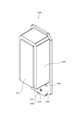
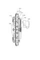
図1及び図2は、本発明の第1実施形態に係る遊技機の外観斜視図及び正面図である。図3は、本実施形態の遊技機に用いられる遊技盤の正面図である。図4は、遊技盤の要部拡大斜視図である。図5は、遊技盤に設けられたLEDユニットの正面図である。本実施形態の遊技機は、一例としてパチンコ遊技機に適用したものである。 1 and 2 are an external perspective view and a front view of the gaming machine according to the first embodiment of the present invention. FIG. 3 is a front view of a gaming board used in the gaming machine of the present embodiment. FIG. 4 is an enlarged perspective view of a main part of the game board. FIG. 5 is a front view of the LED unit provided on the game board. The gaming machine of the present embodiment is applied to a pachinko gaming machine as an example.
[遊技機の構造]
まず、図1~図5を用いて、遊技機としてのパチンコ遊技機の概観について説明する。
[Structure of gaming machine]
First, an overview of the pachinko gaming machine as a gaming machine will be described with reference to FIGS. 1 to 5.
図1及び図2に示すように、本実施形態に係るパチンコ遊技機は、遊技球が転動流下可能な遊技領域を有する遊技盤1(図3参照)が着脱可能に設けられた本体枠ベース板2a(本体枠ベースともいう)を備えた本体枠2と、遊技盤1を視認可能な開口部3h(以下、表枠開口部という)が設けられた表枠ベース板3a(表枠ベースともいう)を備え、本体枠2の前方(遊技者側)において当該本体枠2により回動可能に支持された表枠3と、所定の演出表示を行うための液晶表示装置4(図3参照)が着脱可能に設けられた後枠ベース板(図示略)を備え、本体枠2の後方(反遊技者側)において当該本体枠2により回動可能に支持された後枠(図示略)とを備えている。
As shown in FIGS. 1 and 2, the pachinko gaming machine according to the present embodiment has a main body frame base to which a gaming board 1 (see FIG. 3) having a gaming area in which a gaming ball can roll and flow is detachably provided. A
本実施形態に係るパチンコ遊技機は、外枠6を介して島設備(図示略)に取り付けられている。本体枠2は、本体枠ヒンジ2bを介して外枠6に回動可能に支持されている。なお、図1には、表枠3が本体枠2に対して閉じられているとともに、本体枠2が外枠6に対して閉じられた状態が示されており、かかる状態において、後枠は、外枠6内に収容されるため、図示されない。
The pachinko gaming machine according to the present embodiment is attached to an island facility (not shown) via an
表枠3は、表枠ベース板3aと、表枠ベース板3aに備えられる種々の表枠構成部材とを有している。表枠構成部材には、保護ガラス7、皿ユニット8、操作ユニット9、スピーカ10a~10b、各種装飾部材(トップ飾り14、右側装飾部材15、左側装飾部材16)などがある。なお、表枠構成部材は、これらに限定されるものではなく、表枠3を構成する部材が全て含まれるものである。また、皿ユニット8は、後述する係止構造を介して表枠ベース板3aにそれぞれのカバー部材(上皿上部カバー8a、下皿カバー8bなど)が取り付けられている。
The
表枠3において、上記した表枠開口部3hには、透過性を有する保護ガラス7が設けられている。保護ガラス7は、表枠3に備えられた表枠ベース板3aに設けた表枠開口部3h(窓部)に対して、表枠ベース板3aの裏面側(背面側)から着脱自在に取り付けられており、当該表枠3を本体枠2に対して閉じた状態において、遊技盤1の表面(前面)側に対向し、かつその表面(前面)側を覆うように構成されている。表枠3の上部には、表枠開口部3hの上方両側に、音による演出を行うためのスピーカ10a,10bが設けられている。
In the
また、表枠3の表面(前面)には、表枠開口部3hを囲むように、美観を向上させるための装飾部材が設けられている。なお、装飾部材の一例として、表枠開口部3hの上側には、後述するパトランプ役物を内蔵したトップ飾り14が設けられているとともに、表枠開口部3hの左右には、発光表示態様を変化させることが可能な右側装飾部材15(例えば、右上レンズ15a、右中レンズ15b、右パネルカバー15cなど)と、左側装飾部材16(例えば、左アウターレンズ16aなど)とが設けられている。
Further, on the surface (front surface) of the
右側装飾部材15および左側装飾部材16の内方には、後述する副制御回路70(図6参照)によって制御される発光手段(例えば、ランプ・LED27等)が設けられている(図6参照)。ランプ・LED27から発せられた光は、右側装飾部材15および左側装飾部材16を透過し、当該右側装飾部材15および左側装飾部材16から美観に優れた例えば放射光や拡散光などとして感知される。これにより、光による表示態様に変化を与えることができるため、遊技に対する興趣を向上させることができる。
Inside the right side
さらに、表枠3の表面(前面)には、表枠ベース板3aの表枠開口部3hの下側に、皿ユニット8が設けられている。皿ユニット8は、貸出球や賞球を貯留するための上皿17と、上皿17の下方側に設けられ、例えば上皿17が満杯時に溢れた遊技球などを貯留可能な下皿18とが設けられている。
Further, on the surface (front surface) of the
下皿18は、遊技球を貯留可能な下皿本体18pと、下皿本体18pの上部を覆うように取り付けられた下皿カバー8bとを備えている。一方、上皿17は、遊技球を貯留可能な上皿本体17pと、上皿本体17pの上部を覆うように表枠ベース板3aに対して着脱可能に取り付けられた上皿上部カバー8aと、上皿17の美観を向上させるための上皿装飾部材とを備えている。なお、上皿装飾部材の一例として、上皿本体17pには、上皿上部カバー8aを囲むように、上皿左飾り17a、上皿前飾り17cなどが設けられており、上皿前飾り17cは、上皿上部カバー8aの左側から前側を経由し、右側へ向かう途中から下皿18に向けて屈曲した形状を成している。
The
表枠ベース板3aには、遊技球を上皿17に払い出すための払出口20と、上皿17に貯留された遊技球を表枠ベース板3aの背面側に排出する排出口(図示略)と、排出口から排出された遊技球を下皿18に供給する供給口21とが設けられている。表枠ベース板3aの背面側には、払出装置83(図6参照)から払い出される遊技球の球通路や、排出口と供給口21とを連通させて球通路を構成する球通路カバー(図示略)が設けられている。払出装置83から遊技球が払い出されると、当該遊技球が払出口20を介して上皿17へと送られる一方、遊技球が払い出されるものの払出口20付近に遊技球が滞留するほど上皿17が満杯状態にあるときや、上皿上部カバー8aに設けられた球抜きボタン22が押されると、上皿17に貯留された遊技球が排出口から球通路、供給口21を介して下皿18へと送られる。
The front
本実施形態では、遊技機の前面の装飾にメッキ部材を使用しており、上皿17の前面部分を装飾する上皿前飾り17cにもメッキ部材17bを使用している。このメッキ部材17bの使用により遊技機外観デザインの装飾効果を高めて遊技者の興趣の向上を図っている。
In the present embodiment, the plating member is used for the decoration of the front surface of the gaming machine, and the plating
上皿上部カバー8aには、球貸しを受けるための球貸ボタン23、図示しない遊技球を貸し出すためのカードユニット84(図6参照)からカードを返却するための返却ボタン24などのほか、所定の遊技中に遊技者が操作(押圧操作、回転操作)することで各種演出の表示態様に変化を与えるための操作ユニット9が設けられている。なお、操作ユニット9の配置構成(位置、向き)について、特に制限はないが、図面では一例として、上皿上部カバー8aから垂直方向に押下操作ボタン9Aが突出させられ、押下操作ボタン9Aの外周にジョグダイヤル9Bが配置されるように構成された操作ユニット9が示されている。
The
なお、表枠3については、その表面(前面)のうち、遊技者側から向かって左側(すなわち、本体枠2に回動可能に支持されている側)における部分に、例えばピアノ線などの不正部材を侵入させ、その部分の裏側近傍における当該表枠3の裏面に構築された各種構成に対して、当該不正部材による不正行為が行われる事態を想定することができる。
Regarding the
そこで、かかる不正行為を未然に防止するために、表枠3の裏面において、上記した不正部材による侵入行為が行われる部分には、配線保持機能付きカバー部材(図示略)が設けられている。配線保持機能付きカバー部材は、ハーネス等の配線を保持する配線保持部と、表枠3の裏面に構築された基板(図示しない)を被覆する基板被覆部と、例えばピアノ線等の不正部材の侵入を防止する不正防止部とを一体化させて構成されている。これによれば、配線保持、基板被覆部、不正防止の3つの機能を兼ね備えた単体の配線保持機能付きカバー部材を実現することができるため、これら各機能毎の部材をそれぞれ別個に用意する必要がなくなり、その分だけ低コスト化を図ることができる。
Therefore, in order to prevent such fraudulent activity, a cover member with a wiring holding function (not shown) is provided on the back surface of the
本体枠2は、本体枠ベース板2aと、本体枠ベース板2aに備えられる種々の本体枠構成部材を有する。本体枠構成部材には、発射装置26、スピーカ10c、各種制御基板・中継基板などがある。本体枠構成部材は、これらに限定されるものではなく、本体枠2を構成する部材は全て含まれるものである。
The
本体枠2において、上記した表枠開口部3hに対向した本体枠ベース板2aの所定位置には、当該表枠開口部3hとほぼ同形状を成した本体枠開口部(図示略)が設けられているとともに、当該本体枠ベース板2aの表面(前面)において、本体枠開口部の右下側には、遊技球を発射するための発射装置26が設けられている。
In the
発射装置26は、当該発射装置26を本体枠ベース板2aの表面右下側に配設するためのパネル体26aと、パネル体26aの前面側に配設された発射ハンドル26bと、パネル体26aの背面側に対向した本体枠ベース板2aの表面右下側に配設され、遊技球を発射するための発射駆動装置(図示略)とを備えて構成されている。
The launching
なお、表枠3の右下側には、発射装置26(パネル体26a、発射ハンドル26b)を遊技者側に露出させるための切り欠き3pが施されている。表枠3を本体枠2に対して閉じると、発射装置26(パネル体26a、発射ハンドル26b)は、当該表枠3の切り欠き3pを介して露出し、上記した皿ユニット8に隣接して位置付けられる。このような発射装置26(パネル体26a、発射ハンドル26b)と皿ユニット8とは、相互に連続して一体化されているかの如き美的外観を呈する。
The lower right side of the
発射ハンドル26bは、支持部(図示略)と、支持部に対して回動自在に取り付けられ、時計回り・反時計回り方向に回動可能なハンドルグリップ26dと、支持部内に備えられ、遊技球の発射を停止させる発射停止スイッチ(図示略)と、発射停止スイッチをON/OFF操作する発射停止ボタン26e(操作部材ともいう)と、ハンドルグリップ26dの開口上を覆うように配設されるハンドルキャップ26hとを備えている。
The
発射ハンドル26bのハンドルグリップ26dを時計回り方向に回動させると、その回動量(回転角度)に応じて発射駆動装置の駆動力が増減変更され、そのときの駆動力によって、上皿17に貯留されている遊技球が、遊技盤1の遊技領域1p(図3参照)に向けて所定のタイミングで打ち出される。例えば、本実施形態では、発射駆動装置により1分当り90.9個の遊技球を発射可能であり、略0.66秒ごとに遊技球を1個ずつ発射することができる。このとき、発射停止ボタン26eを操作すると、発射駆動装置が停止制御され、これにより、遊技球の発射を停止させることができる。
When the
なお、本実施形態において、発射停止スイッチや発射ハンドル26bの操作制御にあっては、主制御回路60(図6参照)に接続されている払出・発射制御回路82(図6参照)が行なう。発射装置26の内部には、ハンドルグリップ26dを、常時、反時計回り方向に弾性的に付勢するためのバネ部材(図示略)が設けられており、遊技者は、このバネ部材の弾性に抗してハンドルグリップ26dを時計回り方向に回動操作することにより遊技球を発射させる。
In the present embodiment, the payout / launch control circuit 82 (see FIG. 6) connected to the main control circuit 60 (see FIG. 6) controls the operation of the launch stop switch and the
また、遊技者が遊技を中断してハンドルグリップ26dから手を離すと、ハンドルグリップ26dは、バネ部材の弾性によって開始時点位置に戻される。このとき、ハンドルグリップ26dの突起(図示略)によって発射停止ボタン26eが押されることにより、遊技球の発射が停止される。
Further, when the player interrupts the game and releases the
なお、発射装置26における遊技球の発射強度を増減変更させる方法としては、発射ハンドル26bのハンドルグリップ26dの回動量(回転角度)に応じて、発射ボリューム(図示略)の抵抗値を変化させ、発射ソレノイド(図示略)に供給する電力を変化させることにより、遊技球の発射強度を増減変更させるようになっているが、他の発射装置としては、発射ハンドルのハンドルグリップの回動操作に連動する図示しない発射用ばねと、発射用ばねの巻き上げ(締め上げ)用ギヤ機構とを備えたものでもよい。このような発射装置においては、発射ハンドルのハンドルグリップの回動量によって巻き上げ用ギヤ機構の回動量が調整されて発射用ばねの巻き上げ(締め上げ)の程度を強めたり弱めたりすることにより、遊技球の発射強度を増減変更させることができる。
As a method of increasing or decreasing the firing intensity of the game ball in the
スピーカ10cは、本体枠2の下部中央に、音による演出を行うように設けられている。スピーカ10cから発せられた音は、表枠3の皿ユニット8の部位(具体的には、上皿17と下皿18との間の部位)に設けられたスピーカカバー10kを通して放出されるようになっている。
The
遊技盤1は、保護ガラス7の後方に位置するように、後枠(図示略)の前方に配設され、発射された遊技球が転動流下可能な遊技領域1p(図3参照)を有している。なお、遊技盤1は、透光性を有する材質(例えば、ポリカーボネート等)で形成されているが、例えば、ベニヤ板等のように透光性を有しない材質で形成されていてもよい。
The
図3~図5に示すように、遊技盤1は、第1ガイドレール30、第2ガイドレール30’、ステージ31、第1始動口32、第2始動口33、第2始動口33を開閉する羽根部材34、通過ゲート35、大入賞口37、大入賞口37を開閉する大入賞口シャッタ37A、複数の一般入賞口40、アウト口41、上側可動演出部材42A、下側可動演出部材42B、カバー部材43、液晶表示装置4、及びLEDユニット5を備える。なお、本実施形態のパチンコ遊技機では、第1始動口32、第2始動口33、通過ゲート35、大入賞口37、及び一般入賞口40により遊技球が通過可能な通過領域が形成される。大入賞口シャッタ37Aは、通過領域(大入賞口37)に対して遊技球の通過が容易な開放状態になる第1態様と困難な閉鎖状態になる第2態様とに変位可能な変位部材に相当する。図3は、カバー部材43を取り外した状態を示している。大入賞口37、大入賞口シャッタ37A、及びカバー部材43は、可変入賞装置を構成する部品あるいは部位として設けられている。
As shown in FIGS. 3 to 5, the
第1ガイドレール30は、遊技盤1に向かって左側から概ね中央上部へと延びるように配設され、外レール30Aと内レール30Bとによって構成されている。外レール30Aは、本体枠2に設けられており、遊技領域1p全体を囲むように配置されている。内レール30Bは、外レールとともに遊技球を遊技盤1の上部に案内するためのものであり、遊技盤1の左側において外レール30Aの内側に配設されている。なお、遊技盤1は、本体枠2に対してその背面側から取り付けられている。
The
第2ガイドレール30’は、遊技盤1に向かって右側上部から概ね右側下部へと延びるように配設され、外レール30Cと内レール30Dとによって構成されている。外レール30C及び内レール30Dは、遊技盤1の右側上部から右側下部に配置された大入賞口37へと遊技球を案内するためのものである。外レール30C及び内レール30Dが互いに対向する面には、これら外レール30C及び内レール30Dの間を通って流下する遊技球に当接可能な複数の凸部30Eが所定の間隔で設けられている。これにより、第2ガイドレール30’を通って流下する遊技球は、第2ガイドレール30’の下端から放出されるまでの間に繰り返し凸部30Eに当接することで進行が抑制され、大入賞口37に至るまでに遊技球の進行速度が効果的に減速される。第2ガイドレール30’の下端は、カバー部材43の右側上部近傍に位置する(図4参照)。これにより、第2ガイドレール30’の下端から放出された遊技球は、後述するカバー部材43の上面43aに当接した後、その上面43aに沿って転動しつつ大入賞口37の方へと移動していく。なお、図3には、外レール30Cの凸部30Eと内レール30Dの凸部30Eとが互いに対向しつつ遊技球を案内する方向に沿って等間隔に配置された形態を示しているが、これらの凸部が遊技球を案内する方向に沿って互いにずれた位置で千鳥配列に配置された形態としてもよい。
The second guide rail 30'is arranged so as to extend from the upper right side to the lower right side toward the
ステージ31は、遊技領域1pにおける遊技球の流化領域を振り分けるものであり、液晶表示装置4の下縁部に沿って配置されている。
The
発射装置26によって発射された遊技球は、遊技盤1に打ち込まれた遊技釘(図示略)やステージ31等との衝突により、その進行方向を変えながら遊技盤1の下方に向かって流下する。この過程において、遊技球は、第1始動口32、第2始動口33、大入賞口37、一般入賞口40のいずれかに入賞することで回収され、また、入賞しなかった場合や、通過ゲート35を通過してその後入賞しなかった場合にアウト口41から排出されることで回収される。
The game ball launched by the launching
なお、入賞とは、遊技球が通過領域を通過すること、又は通過領域に入球することを意味する。具体的には、遊技球が通過領域を通過又は通過領域に入球することにより、遊技者にとって有利な状況(例えば、第2始動口33の開放、図柄抽選、賞球など)を付与することを意味する。この際、遊技球による通過領域の通過は、単なる通過を意味し、遊技球による通過領域の入球は、アウト口41とは別に遊技球を回収することを意味するが、何れの場合も後述するセンサスイッチにより遊技球が通過することで入賞が検出されることから、通過も入球も実質的には同義である。したがって、通過領域に対する遊技球の通過も入球も入賞につながるため、以下の説明においては、特に断りのある場合を除き、「入賞」で統一する。
In addition, winning means that the game ball passes through the passing area or enters the passing area. Specifically, by passing the game ball through the passing area or entering the passing area, a situation advantageous to the player (for example, opening of the
発射ハンドル26bの回転角度が比較的小さい場合、遊技球に与えられる打ち出し力が総じて小さいため、遊技球は、主としてステージ31の左側を流下する。また、発射ハンドル26bの回転角度が比較的大きい場合、遊技球に与えられる打ち出し力が総じて大きいため、遊技球は、ステージ31の右側を流下し、あるいは第2ガイドレール30’に沿って流下する。なお、一般に、ステージ31の左側に遊技球を流下させる打ち方は、「左打ち」と呼ばれ、ステージ31の右側や第2ガイドレール30’に沿って遊技球を流下させる打ち方は、「右打ち」と呼ばれている。
When the rotation angle of the
第1始動口32及び第2始動口33は、遊技球が入賞(通過)することを条件に抽選の契機を与えるとともに、抽選の結果をLEDユニット5や液晶表示装置4の表示領域4Aに表示させる契機を与えるものである。
The
第1始動口32は、遊技盤1の中央で概ね下方位置に設けられている。第1始動口32に遊技球が入賞すると、予め設定されている数の遊技球が払出口20又は供給口21を介して上皿17又は下皿18に払い出される。第1始動口32への遊技球の入賞は、第1始動口スイッチ320(図6参照)により検出される。
The
第2始動口33は、第1始動口32の直下に設けられている。第2始動口33に遊技球が入賞すると、予め設定されている数の遊技球が払出口20又は供給口21を介して上皿17又は下皿18に払い出される。第2始動口33は、普通電動役物としての羽根部材34によって入賞困難性が決定される。第2始動口33への遊技球の入賞は、第2始動口スイッチ330(図6参照)により検出される。
The
羽根部材34は、遊技盤1の前後方向に前傾姿勢・後退姿勢をなすように開閉動作するものであり、第2始動口33への遊技球の入賞を可能とする開放状態と、第2始動口33への遊技球の入賞を不可能又は困難とする閉鎖状態とを切り替える、いわゆる普通電動役物である。羽根部材34は、羽根部材ソレノイド340(図6参照)により駆動される。
The
なお、普通電動役物としては、羽根部材34を前後方向に開閉するように動作させるものに限らず、例えば遊技盤1の左右方向に回動することで始動口を拡開するいわゆる電動チューリップ型のものや、遊技盤1の前後方向に水平移動することで始動口を開閉する舌状部材であってもよい。
The ordinary electric accessory is not limited to the one that operates the
通過ゲート35は、第2始動口33を開放する契機を与えるものである。通過ゲート35への遊技球の入賞は、通過ゲートスイッチ350(図6参照)により検出される。なお、この通過ゲート35に遊技球が入賞しても、賞球は発生しない。
The
大入賞口37は、遊技者に有利な遊技状態である当り遊技状態(大当り遊技状態など)のときに開放されるものである。大入賞口37は、遊技領域1pの右側下部にあって、第1始動口32及び第2始動口33の概ね右側に設けられている。なお、大入賞口37が配置される位置については、上述した位置に限らず、遊技機の仕様などに応じて適宜変更することができる。
The
大入賞口37は、複数の遊技球が同時に入賞し得るように比較的左右方向の寸法が大きい開口からなる。大入賞口37は、大入賞口シャッタ37A及びカバー部材43により形成される。大入賞口37は、大入賞口シャッタ37Aが開放状態にある時、遊技盤1の前面とカバー部材43との間に開放口として形成され、大入賞口シャッタ37Aが閉鎖状態にある時に閉鎖口となる。
The large winning
大入賞口シャッタ37Aは、大入賞口37を覆うように左右方向に沿う長手方向寸法が比較的大きい板状部材である。大入賞口シャッタ37Aの短手方向寸法は、遊技球の直径程度である。大入賞口シャッタ37Aは、遊技盤1の前後方向に突出・退避可能に設けられている。大入賞口シャッタ37Aは、遊技盤1の前方に突出した状態が大入賞口37を閉鎖する閉鎖状態となり、遊技盤1の後方へと退避した状態が大入賞口37を開放する開放状態となる。大入賞口シャッタ37Aの上面は、閉鎖状態において比較的緩やかな左下がり傾向の傾斜面になっている。大入賞口シャッタ37Aは、大入賞口シャッタソレノイド370A(図6参照)により開閉可能に駆動される。
The large winning
図4に示すように、カバー部材43は、大入賞口シャッタ37Aに対して対向するように配置される。カバー部材43は、閉鎖状態の大入賞口シャッタ37Aに連接する上面43a、前端ガイド部43b、及び大入賞口37に対応する開口部43cを有する。カバー部材43が遊技盤1に取り付けられた状態において、上面43aは、第2ガイドレール30’の下端下方から大入賞口37(開口部43c)の右端まで延びており、比較的緩やかな左下がり傾向の傾斜面をなす。上面43aは、第2ガイドレール30’から放出された複数の遊技球を支持しつつ左端に位置する大入賞口37(開口部43c)へと導くように配置される。前端ガイド部43bは、起立壁をなし、上面43aの右端から大入賞口37(開口部43c)の左端へと延びるように形成されている。前端ガイド部43bの内面には、遊技球に当接可能な複数の凸部43dが所定の間隔で設けられている。また、前端ガイド部43bに対向する遊技盤1の前面適部にも、遊技球に当接可能な複数の凸部1dが所定の間隔で設けられている。遊技盤1の凸部1dとカバー部材43の凸部43dとは、遊技球の進行方向に沿って互いにずれた位置で千鳥配列に配置されている。これにより、上面43a及び前端ガイド部43bに沿って転動する遊技球は、大入賞口37(大入賞口シャッタ37A)の左端まで移動する間に繰り返し交互に凸部1d,43dに当接することで進行が抑制され、大入賞口37(大入賞口シャッタ37A)を通り過ぎるまでに遊技球の進行速度が効果的に減速される。このような上面43a、大入賞口シャッタ37A、及び前端ガイド部43bは、大入賞口シャッタ37Aが閉鎖状態にある場合に遊技球が流入可能な通路をなし、流入した遊技球の進行を抑制する抑制部430を形成している。カバー部材43が遊技盤1に取り付けられた状態において、開口部43cは、大入賞口シャッタ37Aと対応する位置に配置され、大入賞口37を形成する。このようなカバー部材43の内部に位置する遊技盤1の箇所には、遊技球を回収するための球通路(図示略)や大入賞口カウントスイッチ370が設けられている。開放状態の大入賞口37から落下した遊技球は、球通路を通って大入賞口カウントスイッチ370へと導かれ、この大入賞口カウントスイッチ370により入賞として検出される。その他、大入賞口37に係る詳細な構成・動作については、後述する。
As shown in FIG. 4, the
一般入賞口40は、遊技盤1の適宜位置に一つ以上設けられている。この一般入賞口40に遊技球が入賞すると、抽選が行われないものの、払出装置83(図6参照)により所定数の賞球が払い出される。一般入賞口40への遊技球の入賞は、一般入賞口スイッチ400A,400Bにより検出される。
One or more general winning
本実施形態のパチンコ遊技機では、図6に示すように、後述する主制御回路60により制御される通常遊技状態として、非確変・非時短遊技状態と、特別図柄抽選の当選確率が非確変・非時短遊技状態よりも高くなる確変遊技状態(特別遊技状態)と、普通図柄抽選の当選確率が非確変・非時短遊技状態よりも高くなる時短遊技状態とが存在し、通常遊技状態において特別図柄抽選に当選した場合、大当り遊技状態(特定遊技状態)に移行する。
In the pachinko gaming machine of the present embodiment, as shown in FIG. 6, as the normal gaming state controlled by the
時短遊技状態では、普通図柄抽選の当選確率が高確率状態となるため、普通電動投物としての羽根部材34のサポートによって第2始動口33への入賞が容易となる。この状態は、いわゆる「電サポ」と呼ばれる状態であり、後述する特別図柄ゲームの保留球が貯まり易くなるとともに、第2始動口33への入賞により遊技球の目減りを抑制することができる。具体的にいうと、時短遊技状態とは、普通図柄抽選の当選確率が相対的に高い状態(時短遊技状態1)、特別図柄や普通図柄の変動時間が相対的に短い状態(時短遊技状態2)、普通電動役物としての羽根部材34の開放時間が相対的に長い状態(時短遊技状態3)のうち少なくともいずれか一の状態を意味する。例えば、時短遊技状態には、上記時短遊技状態1、時短遊技状態2、及び時短遊技状態3が任意の組み合わせをもって同時進行する状態も含まれる。このような時短遊技状態においては、大当り遊技状態に移行する可能性が向上する。
In the time-saving game state, the winning probability of the normal symbol lottery is high, so that the support of the
本実施形態においては、大当り遊技状態の終了後に確変・時短遊技状態(確変遊技状態であり、時短遊技状態である通常遊技状態)に必ず移行し、非確変・非時短遊技状態(非確変遊技状態であり、非時短遊技状態である通常遊技状態)に移行しないようになっている。一方、確変・時短遊技状態において大当り遊技状態に移行することなく、特別図柄ゲームの図柄変動回数(ゲーム回数)が所定回数に達した場合は、非確変遊技状態かつ非時短遊技状態である通常遊技状態に移行するようになっている。 In the present embodiment, after the end of the jackpot gaming state, the game always shifts to the probabilistic / short-time gaming state (probable-changing gaming state, which is the normal gaming state which is the time-saving gaming state), and the non-probable / non-short-time gaming state (non-probable changing gaming state). Therefore, it does not shift to the normal gaming state, which is a non-time saving gaming state). On the other hand, if the number of symbol fluctuations (number of games) of the special symbol game reaches a predetermined number without shifting to the jackpot game state in the probabilistic / short-time game state, the normal game is in the non-probable change game state and the non-time-saving game state. It is designed to move to the state.
具体的にいうと、本実施形態では、大当り遊技状態の終了後、確変・時短遊技状態で10回の特別図柄抽選(10回の特別図柄の変動表示又は停止表示)が行われたことを契機に、非確変・非時短遊技状態に移行する。なお、大当り遊技状態の終了後、次の大当り遊技状態に移行するまで、確変・時短遊技状態を維持するようにしてもよい。以下の説明において、本実施形態のような所定回数の特別図柄抽選を行うことで終了する確変遊技状態のことを、ST(Specia1Time)遊技状態とも記載する。 Specifically, in the present embodiment, after the end of the big hit game state, 10 special symbol lottery (10 times special symbol change display or stop display) is performed in the probability change / time saving game state. In addition, it shifts to a non-probable change / non-time saving game state. After the end of the big hit game state, the probability change / time saving game state may be maintained until the next big hit game state is entered. In the following description, the probabilistic gaming state that ends by performing a predetermined number of special symbol lottery as in the present embodiment is also described as an ST (Specia1Time) gaming state.
上側可動演出部材42A及び下側可動演出部材42Bは、非作動時に遊技盤1の背後に退避した状態にあり、特定の演出を行うときに液晶表示装置4の表示領域4Aの前方に出現するように配置されている。上側可動演出部材42Aは、特定の演出が行われる場合に表示領域4Aの中央部の前方に出現し、回転動作及び発光を行う。下側可動演出部材42Bは、特定の演出が行われる場合に表示領域4Aの下部の前方に出現し、発光を行う。
The upper
LEDユニット5は、各遊技状態や抽選結果を遊技者に報知するものであり、図5に示すように、普通図柄表示部51、普通図柄保留表示部52、第1特別図柄表示部53、第2特別図柄表示部54、第1特別図柄保留表示部55、第2特別図柄保留表示部56、及びラウンド表示部59を有している。なお、特に図示しないが、遊技盤1等に配置されたランプ・LED27(図6参照)には、キャラクタ出現報知ランプに対応するものが含まれており、大当り遊技状態への移行が確定した通常遊技状態において特別図柄の変動時の一部や、大当り遊技状態中において液晶表示装置4の表示領域4Aに後述する上乗せキャラクタが出現したときに点灯(又は点滅)するようになっている。
The
普通図柄表示部51は、通過ゲート35に遊技球が入賞したことを契機に普通電動役物としての羽根部材34を駆動して第2始動口33を開放するか否かを決定する「普通図柄ゲーム」に対する抽選結果を表示するものである。普通図柄表示部51は、1つのLEDランプ511を含んでいる。LEDランプ511は、例えば赤色の点灯及び青色の点灯が可能であり、普通図柄ゲームにおいて、当選の場合に赤色で点灯する一方、普通図柄ゲームにおいてハズレの場合に青色で点灯する。普通図柄表示部51におけるLEDランプ511の点灯態様として例えば赤色の点灯態様となったときには、羽根部材34が所定のパターンで開閉駆動され、第2始動口33への遊技球の入賞を許容する。なお、普通図柄ゲームの当選及びハズレに応じた点灯態様としては、他の点灯態様であってもよく、例えば当選の場合に点灯状態あるいは点滅状態になる一方、ハズレの場合に消灯状態となるようにしてもよい。
The ordinary
普通図柄保留表示部52は、4つのLEDランプ521,522,523,524の点灯又は消灯によって、普通図柄表示部51が変動表示を行っている最中に新たな遊技球が通過ゲート35に入賞した場合に次回以降の普通図柄表示部51による変動表示を行うために保留された普通図柄の変動表示の実行可能回数を表示する。4つのLEDランプ521,522,523,524は、普通図柄表示部51の左側に位置し、LEDランプ511とともに列状に並んで配置されている。LEDランプ521,522,523,524による保留表示において、例えば保留数が「1」の場合には、LEDランプ521が点灯し、LEDランプ522,523,524が消灯する。保留数が「2」の場合には、LEDランプ521,522が点灯し、LEDランプ523,524が消灯する。保留数が「3」の場合には、LEDランプ521,522,523が点灯し、LEDランプ524が消灯する。保留数が「4」の場合には、LEDランプ521,522,523,524の全てが点灯する。
In the normal symbol
第1特別図柄表示部53及び第2特別図柄表示部54は、「特別図柄ゲーム」に対する当り抽選の結果を示すものであり、例えば、7セグメントLEDを含んでいる。第1特別図柄表示部53は、第1始動口32への遊技球の入賞を契機として識別情報となる図柄(以下において、「第1特別図柄」と称する)の変動表示を行うとともに、第1始動口32への入賞に基づく当り抽選の結果を第1特別図柄に係る停止図柄として停止表示するものである。第2特別図柄表示部54は、第2始動口33への遊技球の入賞を契機として識別情報となる図柄(以下において、「第2特別図柄」と称する)の変動表示を行うとともに、第2始動口33への入賞に基づく当り抽選の結果を第2特別図柄に係る停止図柄として停止表示するものである。
The first special
第1特別図柄表示部53及び第2特別図柄表示部54による図柄の変動表示は、例えば、7セグメントLED等を用い、各セグメントが個別に点灯・消灯を繰り返すことにより行われる。当り抽選の結果は、第1特別図柄表示部53及び第2特別図柄表示部54の各セグメントの点灯・消灯によって形成されるセグメントパターン(図柄)によって表示される。この際、第1特別図柄で表示される複数の当り図柄と第2特別図柄で表示される複数の当り図柄とは、それぞれ異なる態様となっている。第1特別図柄の当り図柄としては、大当り遊技状態への移行契機となる図柄であって、当該大当り遊技状態終了後に確変遊技状態に移行することを示す「確変1」といった名目の大当り図柄がある(図7参照)。第2特別図柄の当り図柄としては、大当り遊技状態への移行契機となる図柄であって、当該大当り遊技状態終了後に確変遊技状態に移行することを示す「確変1」~「確変6」といった名目の大当り図柄と、いわゆる小当り遊技状態への移行契機となる「小当り」といった名目の小当り図柄とがある(図7参照)。すなわち、第1特別図柄の当り図柄には、小当り遊技状態への移行契機となる小当り図柄がなく、第2特別図柄の当り図柄には、小当り遊技状態への移行契機となる小当り図柄がある。なお、第1特別図柄表示部53及び第2特別図柄表示部54は、7セグメントLED等に限定されず、例えば2つ以上のLEDランプの点灯・消灯の組み合わせによるものでもよい。
The fluctuation display of the symbol by the first special
第1特別図柄保留表示部55は、4つのLEDランプ551,552,553,554を含んでおり、これらのLEDランプ551,552,553,554の点灯又は消灯によって、第1特別図柄表示部53又は第2特別図柄表示部54が特別図柄ゲームに対する図柄の変動表示中に第1始動口32に新たな遊技球が入賞した場合の次回以降の特別図柄ゲームに対する第1特別図柄の変動表示のために保留された第1特別図柄表示部53の変動表示の実行可能回数(保留数)を表示する。第2特別図柄保留表示部56は、4つのLEDランプ561,562,563,564を含んでおり、これらのLEDランプ561,562,563,564の点灯又は消灯によって、第1特別図柄表示部53又は第2特別図柄表示部54が特別図柄ゲームに対する図柄の変動表示中に第2始動口33に新たな遊技球が入賞した場合の次回以降の特別図柄ゲームに対する図柄の変動表示のために保留された第2特別図柄表示部54の変動表示の実行可能回数(保留数)を表示する。第1特別図柄保留表示部55及び第2特別図柄保留表示部56のそれぞれは、上下に並んで配置されており、普通図柄保留表示部52の上側に位置する。第1特別図柄保留表示部55及び第2特別図柄保留表示部56での保留数の表示態様は、普通図柄保留表示部52による保留数の表示態様と同一である。
The first special symbol holding
第1特別図柄保留表示部55及び第2特別図柄保留表示部56は、第1特別図柄表示部53又は第2特別図柄表示部54が変動表示しているときに、第1始動口32へと通じる球通路に設けられた第1始動口スイッチ320(図6参照)、又は第2始動口33へと通じる球通路に設けられた第2始動口スイッチ330(図6参照)によって遊技球が検出された場合、第1特別図柄表示部53又は第2特別図柄表示部54の変動表示の実行(開始)を保留する。第1特別図柄表示部53又は第2特別図柄表示部54において変動表示されていた図柄が停止表示された場合は、保留されていた第1特別図柄表示部53又は第2特別図柄表示部54における図柄の変動表示が開始される。
The first special symbol holding
ここで、第1特別図柄表示部53及び第2特別図柄表示部54の変動表示の実行が保留される回数には上限が設定されており、本実施形態においては、第1始動口32及び第2始動口33への遊技球の入賞による第1特別図柄表示部53及び第2特別図柄表示部54の変動表示の保留数は、それぞれ最大で4個としている。第1特別図柄表示部53に対する第1特別図柄ゲームが4回分保留されている場合には、変動中の第1特別図柄表示部53に対応する第1特別図柄ゲームの情報が、メインRAM63(図6参照)の第1特別図柄始動記憶領域(0)に始動記憶(始動記憶情報)として記憶され、保留されている4回分の第1特別図柄ゲームの情報は、第1特別図柄始動記憶領域(1)~第1特別図柄始動記憶領域(4)に始動記憶として記憶される。第2特別図柄ゲームについても同様に、4回分保留されている場合には、変動中の第2特別図柄に対応する第2特別図柄ゲームの情報が、メインRAM63の第2特別図柄始動記憶領域(0)に始動記憶として記憶され、保留されている4回分の第2特別図柄ゲームの情報は、第2特別図柄始動記憶領域(1)~第2特別図柄始動記憶領域(4)に始動記憶として記憶される。したがって、第1特別図柄表示部53及び第2特別図柄表示部54の双方、すなわち第1始動口32及び第2始動口33への入賞保留数は、合計で最大8個となる。
Here, an upper limit is set for the number of times that the execution of the variable display of the first special
なお、第1特別図柄保留表示部55及び第2特別図柄保留表示部56に代えて、あるいは第1特別図柄保留表示部55及び第2特別図柄保留表示部56に加えて、液晶表示装置4において、第1始動口32への入賞の保留及び第2始動口33への入賞の保留を表示するようにしてもよい。
In addition, in place of the first special symbol
ラウンド表示部59は、当り図柄停止中に点灯するものであり、大当り遊技状態が実行される際の後述するラウンドゲーム(ラウンド遊技)に関する回数として、ラウンド数を示すものである。ラウンド表示部59は、3つのLEDランプ591,592,593を含んでおり、これらのLEDランプ591,592,593の点灯又は消灯によって、大当り遊技状態が実行される際のラウンド数を示す。本実施形態では、基本的にラウンド数が16ラウンド(以下において、「16R」と表記する場合がある)と規定されており、この場合、LEDランプ591が点灯し、LEDランプ592,593が消灯する。なお、ラウンド数(回数)は、ラウンドゲーム(ラウンド遊技)が実行される回数全体を意味する場合と、ラウンドゲームが順次実行される際の順番を示す順序数を意味する場合とがある。ラウンド数について、前者を意味する場合は、例えば「16ラウンド」あるいは「16R」と記し、後者を意味する場合は、例えば「16ラウンド目」あるいは「16R目」等と記す。また、以下の説明においては、「ラウンド遊技」を単に「ラウンド」という場合もある。
The
液晶表示装置4は、図3に示すように、遊技盤1の後方に配置されるとともに、その略中央に遊技者が目視可能となるように表示領域4Aが配設されており、第1始動口32及び第2始動口33への遊技球の入賞に基づく当り抽選の結果のほか、遊技に関する各種の画像、例えば演出用の識別図柄、通常遊技状態での演出画像、大当り遊技状態中の演出画像、デモ表示用の演出画像等を表示するものである。すなわち、液晶表示装置4は、遊技球が第1始動口32又は第2始動口33に入賞したことを条件に識別情報の変動表示を行うようになっている。本実施形態のパチンコ遊技機において、液晶表示装置4は、表示手段を構成しており、この液晶表示装置4、スピーカ10a,10b,10c、及びランプ・LED27が報知手段を構成する。
As shown in FIG. 3, the liquid
[遊技機の電気的構成]
次に、図6を用いて、本実施形態に係るパチンコ遊技機の制御回路について説明する。なお、図6においては、「スイッチ」を「SW」と略記し、「ソレノイド」を「SOL」と略記している。
[Electrical configuration of gaming machines]
Next, the control circuit of the pachinko gaming machine according to the present embodiment will be described with reference to FIG. In FIG. 6, the “switch” is abbreviated as “SW” and the “solenoid” is abbreviated as “SOL”.
図6に示すように、パチンコ遊技機は、遊技の制御を行う主制御手段としての主制御回路60と、遊技の進行に応じた演出の制御を行う副制御手段としての副制御回路70とを有する。
As shown in FIG. 6, the pachinko gaming machine includes a
主制御回路60は、メインCPU61、読み出し専用メモリであるメインROM62、読み書き可能メモリであるメインRAM63、初期リセット回路64、I/Oポート65、コマンド送信手段としてのコマンド出カポート66、及びバックアップコンデンサ67を備えている。主制御回路60は、LEDユニット5を含む各種のデバイス(機器やスイッチ等)と接続されている。
The
メインCPU61は、メインROM62及びメインRAM63と接続されており、メインROM62に記憶されたプログラムにしたがって、各種の処理を実行する機能を有する。
The
主制御回路60には、第1始動口32の後方に配置された第1始動口スイッチ320が接続されている。第1始動口スイッチ320によって遊技球が検出されると、当り抽選が行われる。
A first
主制御回路60には、第2始動口33の後方に配置された第2始動口スイッチ330が接続されている。第2始動口スイッチ330によって遊技球が検出されると、当り抽選が行われる。
A second
これらの第1始動口スイッチ320及び第2始動口スイッチ330は、第1始動口32及び第2始動口33に遊技球が入球したことを検出した場合に入賞したとして、所定の検出信号を主制御回路60に供給する。
These first
主制御回路60には、通過ゲート35の後方に配置された通過ゲートスイッチ350が接続されている。通過ゲートスイッチ350によって遊技球が検出された場合、通過ゲート35に遊技球が入賞したとして、普通図柄抽選が行われる。この普通図柄抽選の結果は、普通図柄表示部51において表示される。なお、普通図柄表示部51において特定の図柄が停止表示された場合には、普通図柄抽選の結果が当選であることを遊技者に把握させる演出画像が液晶表示装置4の表示領域4Aに表示されるようにしてもよい。
A passing
通過ゲートスイッチ350は、通過ゲート35を遊技球が通過したことを検出した場合に入賞したとして、所定の検出信号を主制御回路60に供給する。これにより、通過ゲートスイッチ350は、第2始動口33を開放する契機を与えるものである。
The passing
主制御回路60には、遊技盤1の左側及び右側に位置する一般入賞口40の後方に配置された一般入賞口左スイッチ400A及び一般入賞口右スイッチ400Bが接続されている。一般入賞口左スイッチ400A及び一般入賞口右スイッチ400Bによって遊技球が検出されると、払出装置83により予め設定されている数の賞球が行われる。
The general winning opening
主制御回路60には、大入賞口37の下方に配置された大入賞口カウントスイッチ370が接続されている。大入賞口カウントスイッチ370は、大入賞口37への遊技球の入賞数をカウントするためのものである。大入賞口カウントスイッチ370により遊技球の入賞が検出されると、払出装置83は、予め設定されている数の遊技球を賞球として払出口20又は供給口21を介して上皿17又は下皿18に払い出しを行う。大入賞口カウントスイッチ370は、大入賞口37を遊技球が通過した場合に、所定の検出信号を主制御回路60に供給する。
A large winning
主制御回路60は、大入賞口37を開閉する大入賞口シャッタ37Aを駆動するための大入賞口シャッタソレノイド370Aを制御する。これにより、大入賞口シャッタ37Aは、大入賞口37への遊技球の入賞が可能な開放状態と、遊技球の入賞が不可能又は困難な閉鎖状態とに変化するように駆動される。このような大入賞口シャッタ37Aによる大入賞口37の開放駆動は、第1特別図柄表示部53又は第2特別図柄表示部54において特別図柄が特定の停止表示態様となって、大当り遊技状態に移行された場合に行われる。
The
主制御回路60は、羽根部材34を開閉する羽根部材ソレノイド340を制御する。これにより、普通図柄表示部51において所定の発光態様で普通図柄が停止表示されたときに、羽根部材34が所定の時間、所定の回数だけ開放状態となり、第2始動口33に遊技球を入り易くなる。
The
例えば、本実施形態の普通図柄ゲームにおいて、時短遊技状態ではない遊技状態(本実施形態では「非確変・非時短遊技状態」)における普通図柄の当り確率は、0/257であり、羽根部材34が開放されることはない。一方、高確率状態(時短遊技状態)における普通図柄の当り確率は、例えば257/257であり、これに当選した場合に、羽根部材34が所定時間及び所定回数にわたり開放される。また、普通図柄ゲームにおいて当り図柄となる普通図柄の数は1個であり、第2始動口33の開放時に上限となる入賞カウント数は10カウント(10個)である。
For example, in the normal symbol game of the present embodiment, the hit probability of the normal symbol in the game state other than the time-saving gaming state (“non-probability / non-time-saving gaming state” in the present embodiment) is 0/257, and the
第1特別図柄保留表示部55は、第1特別図柄表示部53又は第2特別図柄表示部54が変動表示しているときに、第1始動口スイッチ320によって遊技球が検出された場合、第1特別図柄表示部53又は第2特別図柄表示部54において変動表示中の第1特別図柄又は第2特別図柄が停止表示されるまで、第1始動口32への遊技球の入賞に基づく第1特別図柄の変動表示の実行(開始)が保留される数、すなわち第1特別図柄に係る保留数を表示する。変動表示していた第1特別図柄又は第2特別図柄が停止表示された場合には、第1特別図柄に係る保留数として保留されていた第1特別図柄の変動表示が開始される。
The first special symbol holding
第2特別図柄保留表示部56は、第1特別図柄表示部53又は第2特別図柄表示部54が変動表示しているときに、第2始動口スイッチ330によって遊技球が検出された場合、第1特別図柄表示部53又は第2特別図柄表示部54において変動表示中の第1特別図柄又は第2特別図柄が停止表示されるまで、第2始動口33への遊技球の入賞に基づく第2特別図柄の変動表示の実行(開始)が保留される数、すなわち第2特別図柄に係る保留数を表示する。変動表示していた第1特別図柄又は第2特別図柄が停止表示された場合には、第2特別図柄に係る保留数として保留されていた第2特別図柄の変動表示が開始される。
The second special symbol holding
ここで、本実施形態のパチンコ遊技機において、第1特別図柄及び第2特別図柄の変動表示の優先順位は、第2特別図柄の方が第1特別図柄よりも優先するように設定されている。なお、第1始動口32及び第2始動口33への入賞順にしたがって、対応する第1特別図柄及び第2特別図柄を入賞順通りに変動表示させるようにしてもよい。
Here, in the pachinko gaming machine of the present embodiment, the priority of the variable display of the first special symbol and the second special symbol is set so that the second special symbol has priority over the first special symbol. .. Therefore, the corresponding first special symbol and the second special symbol may be varied and displayed in the order of winning in the order of winning the
また、特別図柄の変動表示の実行が保留される保留数には、先述したように上限が設定されており、本実施形態において、メインCPU61は、第1始動口32及び第2始動口33に遊技球が入賞して第1始動口スイッチ320及び第2始動口スイッチ330によって遊技球が検出されたときの第1特別図柄及び第2特別図柄の変動表示の保留数を、それぞれ最大で4個(すなわち、4検出回数)まで記憶させており、5個目以降は保留数として記憶させないようになっている。この際、特別図柄の変動表示の終了により保留数が減った時には、再び保留数が4個を上限として加算される。
Further, as described above, an upper limit is set for the number of pending executions of the variable display of the special symbol, and in the present embodiment, the
第1特別図柄表示部53における第1特別図柄ゲームの保留数が例えば4個まで保留される場合、変動中の第1特別図柄表示部53に対応する特別図柄ゲームの情報は、メインRAM63の第1特別図柄始動記憶領域(0)に始動記憶として記憶され、以降、保留数が4個分の特別図柄ゲームの情報は、メインRAM63の第1特別図柄始動記憶領域(1)~(4)に始動記憶として順次記憶される。
When the number of reserved first special symbol games in the first special
第2特別図柄表示部54における第2特別図柄ゲームについても同様に、第2特別図柄ゲームの保留数が例えば4個まで保留される場合、変動中の第2特別図柄表示部54に対応する第2特別図柄ゲームの情報は、メインRAM63の第2特別図柄始動記憶領域(0)に始動記憶として記憶され、以降、保留数が4個分の第2特別図柄ゲームの情報は、メインRAM63の第2特別図柄始動記憶領域(1)~(4)に始動記憶として順次記憶される。
Similarly, for the second special symbol game in the second special
したがって、第1始動口32及び第2始動口33への入賞に伴う特別図柄ゲームに係る遊技球の保留数は、合計で最大8個となり、第1特別図柄保留表示部54及び第2特別図柄保留表示部56のLEDランプ551~554及びLEDランプ561~564による保留表示数もそれぞれ4個となる。
Therefore, the total number of game balls held for the special symbol game associated with winning the
大入賞口シャッタ37Aによる大入賞口37の開放状態は、大入賞口カウントスイッチ370によるカウント値(遊技球の入賞数)が所定数(本実施形態では入賞数1個)となるか、あるいは予め規定された後述の開放時間を経過するといったいずれか一方の条件を満たすまで維持される。遊技球の入賞数が所定数となった場合、又は大入賞口シャッタ37Aの開放時間が経過した場合は、大入賞口シャッタ37Aが大入賞口37を閉鎖するように駆動される。
In the open state of the large winning
大当り遊技状態では、後述する予め設定された大入賞口開閉パターン(当りパターン)に基づき、大入賞口37の開放状態と閉鎖状態とが繰り返される。大当り遊技状態において、大入賞口37が後述する大入賞口開閉パターン(当りパターン)に基づいて複数回数にわたり開放状態及び閉鎖状態となる遊技は、「ラウンドゲーム(ラウンド遊技)」という。ラウンドゲーム(ラウンド遊技)は、単にラウンドという場合もある。1回のラウンドゲームにより大入賞口37が閉鎖状態とされてから、次回のラウンドゲームとして大入賞口37が開放状態となるまでの状態については、「ラウンド間ゲーム」又は「ラウンド間インターバル」あるいは単に「インターバル」ともいう。なお、本実施形態では、1回のラウンドにおいて大入賞口37が1回だけ開放状態及び閉鎖状態となるが、他の例においては、1回のラウンドで大入賞口37が複数回にわたり開放状態及び閉鎖状態となる場合もある。また、複数の大入賞口が設けられている場合は、1回のラウンドにおいて、複数の大入賞口の開閉状態を排他的に制御することも可能である。すなわち、1回のラウンドにおいては、一方の大入賞口が所定回数繰り返し開放状態となる間、その余の大入賞口が継続して閉鎖状態とされる。
In the big hit game state, the open state and the closed state of the big winning
なお、本実施形態のパチンコ遊技機には、大当り遊技状態とは異なる性質の遊技状態として、いわゆる小当り遊技状態が設けられている。小当り遊技状態は、大当り遊技状態とは異なりラウンドゲームという概念によって規定されず、本実施形態の小当り遊技状態では、大入賞口37が1回だけ開放状態とされるように規定されている。もちろん、小当り遊技状態においては、任意あるいは特定の大入賞口を複数回数にわたり繰り返し開放状態となるように制御してもよい。この小当り遊技状態とは、特別図柄抽選による小当りの当選を契機に移行する遊技状態である。小当り遊技状態に移行する前とその終了後においては、基本的に遊技状態が変化しない。例えば、非確変遊技状態において小当り当選となって小当り遊技状態に移行した場合、この小当り遊技状態の終了後の遊技状態は、小当り遊技状態に移行する前の非確変遊技状態のままであり、確変遊技状態に移行することはない。同様に、確変遊技状態において小当り当選となって小当り遊技状態に移行した場合、この小当り遊技状態の終了後の遊技状態は、確変遊技状態のゲーム数が残存する限り、小当り遊技状態に移行する前の確変遊技状態のままであり、非確変遊技状態に移行することもない。
The pachinko gaming machine of the present embodiment is provided with a so-called small hit gaming state as a gaming state having a property different from that of the big hit gaming state. Unlike the big hit game state, the small hit game state is not defined by the concept of a round game, and in the small hit game state of the present embodiment, the big winning
ラウンドゲームは、1ラウンド、2ラウンドのようにラウンド数(回数)として計数される。例えば、1回目のラウンドゲームを第1ラウンド、2回目のラウンドゲームを第2ラウンドと称する場合がある。以下の説明(説明に伴い参照する図面を含む)において、1ラウンドあるいは第1ラウンド等の数字付の「ラウンド」に関しては、例えば、1R、2R、4R、16R、等のように、単に「R]の文字で省略する場合がある。なお、1回のラウンドゲームにおいて、大入賞口が所定回数開放状態となる場合、その開放状態となる前に、1ラウンドあたりの規定入賞数に達した場合は、大入賞口が閉鎖状態となり、残りの開放回数分について大入賞口が開放状態とされることなく、当該ラウンドゲームが終了させられることとなる。 Round games are counted as the number of rounds (number of times) such as 1 round and 2 rounds. For example, the first round game may be referred to as a first round, and the second round game may be referred to as a second round. In the following description (including drawings referred to in the description), the "round" with numbers such as the first round or the first round is simply "R" such as 1R, 2R, 4R, 16R, etc. ] May be omitted. In one round game, if the large winning openings are opened a predetermined number of times, or if the specified number of winnings per round is reached before the opening. Will close the big winning opening, and the round game will be terminated without opening the big winning opening for the remaining number of openings.
液晶表示装置4の表示領域4Aには、第1特別図柄表示部53及び第2特別図柄表示部54において表示される特別図柄と関連する演出画像が表示される。例えば、第1特別図柄表示部53及び第2特別図柄表示部54で表示される特別図柄の変動表示中において、特定の場合を除いて、液晶表示装置4の表示領域4Aには、数字からなる図柄(装飾図柄)、例えば、「0」、「1」、「2」・・・「7」のような数字が3列変動表示される。
In the
一方、第1特別図柄表示部53及び第2特別図柄表示部54において変動表示されていた特別図柄が停止表示されると、液晶表示装置4の表示領域4Aにおいても装飾図柄が停止表示される。
On the other hand, when the special symbol that has been variablely displayed on the first special
また、第1特別図柄表示部53及び第2特別図柄表示部54において、変動、停止された特別図柄が特定の停止表示態様である場合には、「大当り」であることを遊技者に把握させる演出画像が液晶表示装置4の表示領域4Aにおいて表示される。
Further, in the first special
具体的には、第1特別図柄表示部53及び第2特別図柄表示部54のいずれか一方において特別図柄が、例えば、多くの出球が獲得可能な「大当り」に対応する特定の表示態様で停止表示された場合には、液晶表示装置4の表示領域4Aにおいて表示される演出用の装飾図柄の組み合わせが特定の表示態様(例えば、複数の図柄列のそれぞれに同一の図柄がすべて揃った状態で停止表示される態様)となり、さらに、大当り用の演出画像が液晶表示装置4の表示領域4Aにおいて表示される。
Specifically, in either the first special
上記したメインCPU61の制御の具体例については、後述する。
A specific example of the control of the
メインROM62は、後述する各種の処理をメインCPU61に実行させるためのプログラムや、各種テーブルを記憶している。
The
メインRAM63は、メインCPU61の一時記憶領域として、種々のデータ(フラグ、カウンタ、タイマ、及び変数の値等)を記憶する機能を有する。メインCPU61の一時記憶領域としては、メインRAM63に代えて、他の読み書き可能な記憶媒体を用いることもできる。
The
初期リセット回路64は、電源投入時においてリセット信号を生成するものであり、メインCPU61に接続されている。
The
I/Oポート65は、各種のデバイスからの入力信号をメインCPU61に、メインCPU61からの出力信号を各種のデバイスに送信するものである。
The I /
コマンド出カポート66は、メインCPU61からの各種コマンドを副制御回路70に送信するものである。
The
バックアップコンデンサ67は、電断時において、メインRAM63に対して速やかに電源を供給することにより、メインRAM63に記憶されている種々のデータを保持するためのものである。
The
主制御回路60に接続される各種のデバイスには、大入賞口シャッタソレノイド370A、羽根部材ソレノイド340、及び外部端子板80が含まれる。
Various devices connected to the
外部端子板80は、ホール係員を呼び出す機能や大当り回数を表示するといった機能を有する図示しない呼出装置、あるいはホールに設置された複数のパチンコ遊技機を管理するホールコンピュータ100等の外部機器との間でデータ通信するためのものである。
The external
主制御回路60に接続される各種のスイッチには、第1始動口スイッチ320、第2始動口スイッチ330、通過ゲートスイッチ350、大入賞口カウントスイッチ370、一般入賞口左スイッチ400A、一般入賞口右スイッチ400B、及びバックアップクリアスイッチ81が含まれる。
Various switches connected to the
バックアップクリアスイッチ81は、電断時等における主制御回路60及び後述する払出・発射制御回路82のバックアップデータを、ホール管理者の操作に応じてクリアするものである。
The backup
また、主制御回路60には、払出・発射制御回路82を介して、発射装置26、払出装置83、及びカードユニット84が接続されている。
Further, the launching
主制御回路60は、払出・発射制御回路82に賞球制御コマンドを送信する。払出・発射制御回路82は、主として発射装置26及び払出装置83を制御するものであり、発射装置26、払出装置83、及びカードユニット84が接続されている。本実施形態のパチンコ遊技機において、払出・発射制御回路82及び払出装置83は、遊技価値付与手段を実現している。
The
カードユニット84は、遊技者の操作に応じて遊技球の貸し出しを要求する信号を出力する球貸し操作パネル85と接続されており、この球貸し操作パネル85との間で信号を送受信可能である。
The
払出・発射制御回路82は、主制御回路60から供給される賞球制御コマンドと、カードユニット84から供給される貸し球制御信号とを受け取り、払出装置83に対して所定の信号を送信することにより、払出装置83に遊技球を払い出させる。払出装置83は、例えば、第1始動口32又は第2始動口33への入賞1個あたり賞球数として3個の遊技球を払い出し、一般入賞口40への入賞1個あたり賞球数として10個の遊技球を払い出し、大入賞口37への入賞1個あたり賞球数として15個の遊技球を払い出す。
The payout /
払出・発射制御回路82は、発射装置26の発射ハンドル26bが遊技者によって握持され、かつ、時計回りの方向へ回動操作された場合に、その回動量に応じて発射ソレノイド(図示略)に電力を供給し、遊技球を遊技領域1pに向けて発射させる制御を行う。
The payout /
メインCPU61は、後述するメイン処理の実行中であっても、メイン処理を中断し割込処理としてのタイマ割込処理を実行する。タイマ割込処理は、所定時間(例えば、2ms)毎に発生する割込条件を契機として実行される。
The
副制御回路70は、主制御回路60に接続されており、主制御回路60からコマンドが供給されるように構成されている。
The
副制御回路70は、主制御回路60から供給される各種のコマンドに応じて、各種の制御を行うものであり、サブCPU71、プログラムROM72、ワークRAM73、コマンド入力ポート74、バックアップコンデンサ75、表示制御回路76、音声制御回路77、ランプ制御回路78、及び可動演出装置制御回路79を有する。表示制御回路76には、液晶表示装置4が接続されている。音声制御回路77には、スピーカ10a,10b,10cが接続されている。ランプ制御回路78には、ランプ・LED27が接続されている。可動演出装置制御回路79は、上側可動演出部材42A及び下側可動演出部材42Bを駆動するモータや機構などを備えた可動演出装置42が接続されている。
The
また、副制御回路70は、押下操作ボタン9Aに設けられた押下操作ボタンスイッチ90Aが接続されているとともに、ジョグダイヤル9Bに設けられたジョグダイヤルスイッチ90Bが接続されている。押下操作ボタンスイッチ90Aは、押下操作ボタン9Aの操作を検知するものであり、ジョグダイヤルスイッチ90Bは、ジョグダイヤル9Bの回転方向や回転角度を識別するものである。副制御回路70には、押下操作ボタンスイッチ90Aから押下操作信号が供給され、ジョグダイヤルスイッチ90Bから回転操作信号が供給される。
Further, in the
サブCPU71は、プログラムROM72に記憶されたプログラムにしたがって、各種の処理を実行する機能を有する。液晶表示装置4は、表示手段として機能する。特に、サブCPU71は、主制御回路60から供給される各種のコマンドにしたがって、副制御回路70全体の制御を行う。
The
上記したサブCPU71の制御の具体例については、後述する。
A specific example of the control of the
プログラムROM72は、サブCPU71が主として各種演出を制御するためのプログラムや各種のテーブルを記憶している。
The
ワークRAM73は、サブCPU71の一時記憶領域として種々のデータ(フラグ、カウンタ、タイマ、及び変数の値等)を記憶するものである。
The
コマンド入力ポート74は、主制御回路60のメインCPU61から送信された各種コマンドを受信し、サブCPU71へと伝えるものである。
The
バックアップコンデンサ75は、電断時において、ワークRAM73に対して速やかに電源を供給することにより、ワークRAM73に記憶されている種々のデータを保持するためのものである。
The
表示制御回路76は、サブCPU71から供給されるデータに応じて、液晶表示装置4における表示制御を行うためのものであり、例えば画像データプロセッサ(VDP)と、各種の画像データを生成するためのデータが記憶されている画像データROMと、画像データを一時記憶するフレームバッファと、画像データを画像信号として変換するD/Aコンバータとから構成されている。なお、表示制御回路76の構成は、あくまでも一例であり、これに限定されるものではない。
The
表示制御回路76は、サブCPU71から供給される画像表示命令に応じて、液晶表示装置4の表示領域4Aに表示させるための画像データを一時的にフレームバッファに格納する。画像データとしては、例えば装飾図柄画像データ、背景画像データ、各種演出用画像データ、各種不正報知画像データ等が含まれる。
The
また、表示制御回路76は、所定のタイミングで、フレームバッファに格納された画像データをD/Aコンバータに供給する。D/Aコンバータは、画像データを画像信号として変換し、所定のタイミングで、この画像信号を液晶表示装置4に供給する。液晶表示装置4の表示領域4Aには、D/Aコンバータからの画像信号に基づいて画像が表示される。
Further, the
音声制御回路77は、スピーカ10a,10b,10cから発生させる音声などに関する制御を行うためのものであり、例えば音声などに関する制御を行う音源IC、各種の音声データを記憶する音声データROM、音声信号を増幅するための増幅器(AMP)を含んでいる。なお、音声制御回路77の構成も、あくまでも一例であり、これに限定されるものではない。
The
音源ICは、スピーカ10a,10b,10cから発生させる音声の制御を行うものであり、サブCPU71から供給される音声発生命令に応じて、音声データROMに記憶されている複数の音声データから一つの音声データを選択することができる。
The sound source IC controls the voice generated from the
また、音源ICは、選択された音声データを音声データROMから読み出し、音声データを所定の音声信号に変換し、その音声信号を増幅器に供給する。なお、この増幅器は、音声信号を増幅させ、スピーカ10a,10b,10cから音声を発生させる。
Further, the sound source IC reads the selected audio data from the audio data ROM, converts the audio data into a predetermined audio signal, and supplies the audio signal to the amplifier. It should be noted that this amplifier amplifies the audio signal and generates audio from the
ランプ制御回路78は、装飾ランプ等を含むランプ・LED27の制御を行うためのものであり、ランプ制御信号を供給するためのドライブ回路、複数種類のランプ装飾パターンが記憶されている装飾データROM等から構成されている。なお、ランプ制御回路78の構成も、あくまでも一例であり、これに限定されるものではない。
The
可動演出装置制御回路79は、例えば、大当り遊技状態において、操作ユニット9に対する操作の有効期間中に押下操作ボタン9Aの操作等によって上側可動演出部材42A及び下側可動演出部材42Bを作動(揺動等でもよい)させる等の演出動作を制御する。
The movable effect
[遊技機のスペック]
次に、図7を用いて、本実施形態に係るパチンコ遊技機の遊技特性に関するスペックについて説明する。
[Game machine specifications]
Next, with reference to FIG. 7, specifications relating to the gaming characteristics of the pachinko gaming machine according to the present embodiment will be described.
図7に示すように、本実施形態において、大当り遊技状態となる特別図柄の大当り確率は、低確率時(非確変遊技状態)にあっては1/99.75(657/65536)、高確率時(確変遊技状態)にあっては1/13.05(5020/65536)となっている。小当り遊技状態となる特別図柄の小当り確率は、第1特別図柄及び第2特別図柄のいずれにおいても1/29.92(2190/65536)となっている。第1特別図柄と第2特別図柄との消化順序は、第2特別図柄による抽選を優先して消化する。確率変動性能(確変遊技状態の仕様)としては、確変遊技状態がゲーム回数(特別図柄の変動回数)として最大10回まで継続するST遊技状態が実装されている。 As shown in FIG. 7, in the present embodiment, the jackpot probability of the special symbol in the jackpot gaming state is 1 / 99.75 (657/65536) at the time of low probability (non-probability variable gaming state), which is a high probability. At the time (probability change game state), it is 1 / 13.05 (5020/65536). The small hit probability of the special symbol in the small hit game state is 1 / 29.92 (2190/65536) in both the first special symbol and the second special symbol. As for the digestion order of the first special symbol and the second special symbol, the lottery by the second special symbol is prioritized and digested. As the probability fluctuation performance (specification of the probability variation game state), the ST game state in which the probability variation game state continues up to 10 times as the number of games (the number of fluctuations of the special symbol) is implemented.
特別図柄の振り分けについては、以下のようになっている。すなわち、第1特別図柄の大当り図柄「確変1」では、大入賞口開閉パターン(当りパターン)が当りパターン1となり、ラウンドゲームのラウンド数として16R(そのうち大入賞口に入賞容易な実質ラウンド数は7R)が付与され、大当り遊技状態の演出モード示すボーナス名としては「ノーマルボーナス」となり、ボーナス内容としては「7Rボーナス」となっている。この「ノーマルボーナス」は、大入賞口37への入賞について、1R目~7R目の推定入賞数が1個で8R目~16R目の推定入賞数が0個とされる。これにより、「ノーマルボーナス」では、予定賞球数が105個となっている。第1特別図柄の大当り図柄として「確変1」となる確率(突入率)は、100/100に設定されている。なお、本実施形態において「ボーナス」とは、賞球数に関係する報知演出を意味する。
The distribution of special symbols is as follows. That is, in the big hit symbol "
第2特別図柄の大当り図柄「確変1」では、当りパターン2となり、ラウンド数16R(実質ラウンド数も16R)が付与され、ボーナス名としては「大上乗せボーナス」となり、ボーナス内容としては「大上乗せボーナス」となっている。「大上乗せボーナス」は、大入賞口37への入賞について、1R目~7R目の推定入賞数が1個で8R目~16R目の推定入賞数が4個とされる。これにより、「大上乗せボーナス」では、予定賞球数が645個となっている。第2特別図柄の大当り図柄として「確変1」となる確率(突入率)は、35/100に設定されている。
In the big hit symbol "
第2特別図柄の大当り図柄「確変2」では、当りパターン3となり、ラウンド数16R(実質ラウンド数も16R)が付与され、ボーナス名としては「中上乗せボーナス1」となり、ボーナス内容としては「中上乗せボーナス1」となっている。「中上乗せボーナス1」は、大入賞口37への入賞について、1R目~7R目の推定入賞数が1個で8R目~16R目の推定入賞数が3個とされる。これにより、「中上乗せボーナス1」では、予定賞球数が510個となっている。第2特別図柄の大当り図柄として「確変2」となる確率(突入率)は、20/100に設定されている。
In the big hit symbol "
第2特別図柄の大当り図柄「確変3」では、当りパターン4となり、ラウンド数16R(実質ラウンド数も16R)が付与され、ボーナス名としては「中上乗せボーナス2」となり、ボーナス内容としては「中上乗せボーナス2」となっている。「中上乗せボーナス2」は、大入賞口37への入賞について、1R目~7R目の推定入賞数が1個、8R目及び9R目の推定入賞数が2個、10R目及び11R目の推定入賞数が3個、12R目の推定入賞数が1個、13R目~16R目の推定入賞数が4個とされる。これにより、「中上乗せボーナス2」では、予定賞球数が510個となっている。第2特別図柄の大当り図柄として「確変3」となる確率(突入率)は、10/100に設定されている。
In the big hit symbol "
第2特別図柄の大当り図柄「確変4」では、当りパターン5となり、ラウンド数16R(実質ラウンド数も16R)が付与され、ボーナス名としては「小上乗せボーナス1」となり、ボーナス内容としては「小上乗せボーナス1」となっている。「小上乗せボーナス1」は、大入賞口37への入賞について、1R目~7R目の推定入賞数が1個で8R目~16R目の推定入賞数が2個とされる。これにより、「小上乗せボーナス1」では、予定賞球数が375個となっている。第2特別図柄の大当り図柄として「確変4」となる確率(突入率)は、15/100に設定されている。
In the big hit symbol "
第2特別図柄の大当り図柄「確変5」では、当りパターン6となり、ラウンド数16R(実質ラウンド数も16R)が付与され、ボーナス名としては「小上乗せボーナス2」となり、演出内容としては「小上乗せボーナス2」となっている。「小上乗せボーナス2」は、大入賞口37への入賞について、1R目~13R目の推定入賞数が1個で14R目~16R目の推定入賞数が4個とされる。これにより、「小上乗せボーナス2」では、予定賞球数が375個となっている。第2特別図柄の大当り図柄として「確変5」となる確率(突入率)は、10/100に設定されている。
In the big hit symbol "
第2特別図柄の大当り図柄「確変6」では、当りパターン7となり、ラウンド数16R(実質ラウンド数も16R)が付与され、ボーナス名としては「上乗せ無しボーナス」となり、ボーナス内容としては「上乗せ無しボーナス」となっている。「上乗せ無しボーナス」は、大入賞口37への入賞について、1R目~16R目の推定入賞数が1個とされる。これにより、「上乗せ無しボーナス」では、予定賞球数が240個となっている。第2特別図柄の大当り図柄として「確変6」となる確率(突入率)は、10/100に設定されている。
In the big hit symbol "
第1特別図柄又は第2特別図柄の小当り図柄では、当りパターン8となり、ボーナス名及びボーナス内容としては「小当り」となっている。小当り図柄の突入率は、100/100に設定されている。なお、小当り遊技状態には、大当り遊技状態とは異なりラウンドゲームという概念がないので、ラウンド数が規定されていない。 In the small hit symbol of the first special symbol or the second special symbol, the hit pattern is 8, and the bonus name and the bonus content are "small hit". The inrush rate of the small hit symbol is set to 100/100. In the small hit game state, unlike the big hit game state, there is no concept of a round game, so the number of rounds is not specified.
大入賞口カウント数は、1ラウンドにおいて大入賞口37を開放状態から閉鎖状態とする際の一契機となる規定入賞数に該当し、本実施形態では、大入賞口カウント数(規定入賞数)が「1」に設定されている。すなわち、1ラウンドにおいて大入賞口37への入賞が1個計数されると、大入賞口37が開放状態から閉鎖状態とされる。なお、大入賞口カウント数(規定入賞数)は、1ラウンドにおける入賞数の上限を定めたものではない。すなわち、1ラウンド中に例えば大入賞口カウント数を超える入賞が検出された場合にあっても、その入賞数に応じた賞球数が払い出される。これにより、大入賞口カウント数を超えるオーバー入賞が可能となっている。この点については後述する。
The number of large winning openings count corresponds to the specified number of winning openings that triggers the change from the open state to the closed state of the large winning
時短性能(時短遊技状態の仕様)としては、高確率の間(確変遊技状態にある間)、時短遊技状態が継続するように設定されている。賞球数は、始動口(第1始動口32及び第2始動口33)への入賞1個あたり3個となり、一般入賞口40への入賞1個あたり10個となり、大入賞口37への入賞1個あたり15個となるように設定されている。普通図柄の当り確率は、低確率時に0/257となり、高確率時に257/257となるように設定されている。普通図柄の当り図柄数は、1個に設定されている。第2始動口33の開放時における入賞カウント数は、上限として10個まで計数するように設定されている。
The time-saving performance (specification of the time-saving gaming state) is set so that the time-saving gaming state continues during a high probability (while in the probability variation gaming state). The number of prize balls is 3 for each winning opening (
なお、スペックとしては、次のような内容であってもよい。例えば、特別図柄については、低確率時及び高確率時の大当り確率が上記したものに限定されるものではない。すなわち、特別図柄の大当り確率は、高確率時の方が低確率時よりも大当りに当選し易い確率であればよい。小当り確率についても、上記したものに限定されるものではない。例えば、一方の特別図柄よりも他方の特別図柄における当選確率が高くなる仕様であってもよい。特別図柄の消化順については、第1特別図柄及び第2特別図柄について優先順を設定せずに入賞順としてもよいし、第1特別図柄を優先消化する仕様としてもよい。確変遊技状態(ST遊技状態)が継続するST回数は、上記したものに限定されるものではない。また、次回の大当り当選まで確変遊技状態が継続するようにしてもよい。ラウンド数は、上記したものに限定されず、16R以外の他のラウンド数を設けてもよい。実質ラウンド数については、全て正規のラウンド数と同数となるようにしてもよい。大当り図柄の種類は、上記したものに限定されない。例えば、第1特別図柄の大当り図柄の種類を多くしてもよい。また、第1特別図柄に基づく大当り遊技状態でも、上乗せボーナスを実行するようにしてもよい。本実施形態において、大入賞口カウント数(規定入賞数)は、「1」に設定されているが、これに限定されるものではない。例えば、大入賞口カウント数を2以上に設定してもよい。そうした場合、大入賞口カウント数より多くの遊技球を同時に通過可能とする大入賞口シャッタなどを設けることが望ましい。時短性能は、ST回数(確変遊技状態のゲーム数)より多くてもよいし、あるいは例えば0回も含めてST回数より少なくてもよい。賞球数は、上記したものに限定されるものではない。例えば、大入賞口に係る賞球数を上記したものとは異なる値に設定した場合は、その値と推定入賞数とを用いて予定賞球数を算出し、後述する上乗せ数の報知を行うようにすることができる。普通図柄に関しては、低確率時及び高確率時の当り確率が上記したものに限定されるものではない。例えば、普通図柄の当り確率は、高確率時の方が低確率時よりも当選し易い確率であればよく、例えば低確率時に当選するようにしてもよい。普通図柄の当り図柄数は、上記したものに限定されず、例えば2個以上としてもよい。2個以上の場合には、羽根部材の開放パターンがそれぞれ異なるように対応付けられることが好ましい。第2始動口の入賞カウント数は、上記したもの以外の値としてもよい。 The specifications may have the following contents. For example, for special symbols, the jackpot probabilities at low probability and high probability are not limited to those described above. That is, the jackpot probability of the special symbol may be such that the probability of winning the jackpot is easier in the high probability than in the low probability. The small hit probability is not limited to the above. For example, it may be a specification in which the winning probability in the other special symbol is higher than that in one special symbol. Regarding the digestion order of the special symbols, the first special symbol and the second special symbol may be set in the winning order without setting the priority order, or the first special symbol may be preferentially digested. The number of STs in which the probabilistic gaming state (ST gaming state) continues is not limited to the above. In addition, the probabilistic game state may be continued until the next big hit. The number of rounds is not limited to those described above, and a number of rounds other than 16R may be provided. The actual number of rounds may be the same as the regular number of rounds. The type of jackpot symbol is not limited to the above. For example, the types of jackpot symbols of the first special symbol may be increased. Further, even in the big hit game state based on the first special symbol, the additional bonus may be executed. In the present embodiment, the number of large winning opening counts (specified winning number) is set to "1", but the number is not limited to this. For example, the number of large winning openings may be set to 2 or more. In such a case, it is desirable to provide a large winning opening shutter or the like that allows more game balls to pass at the same time than the number of large winning opening counts. The time saving performance may be larger than the number of STs (the number of games in the probabilistic gaming state), or may be less than the number of STs including, for example, 0 times. The number of prize balls is not limited to those described above. For example, if the number of prize balls related to the large prize opening is set to a value different from the above value, the planned number of prize balls is calculated using the value and the estimated number of prizes, and the additional number described later is notified. Can be done. With respect to ordinary symbols, the hit probabilities at low probability and high probability are not limited to those described above. For example, the probability of winning a normal symbol may be as long as it is easier to win in the high probability than in the low probability, and for example, the winning may be made in the low probability. The number of hit symbols of ordinary symbols is not limited to those described above, and may be, for example, two or more. In the case of two or more, it is preferable that the opening patterns of the blade members are associated with each other so as to be different. The winning count number of the second starting port may be a value other than those described above.
[1ラウンド開閉パターン]
次に、図8を用いて、1ラウンドにおける大入賞口の開閉パターンについて説明する。
[1 round opening / closing pattern]
Next, with reference to FIG. 8, the opening / closing pattern of the large winning opening in one round will be described.
図8に示すように、大入賞口37について1ラウンドの開閉パターン(1ラウンド開閉パターン)としては、3種類の開閉パターンA~Cが規定されている。開閉パターンA~Cは、大当り遊技状態に対応する開閉パターンであり、そのうちの開閉パターンCは、小当り遊技状態にも対応する開閉パターンである。なお、小当り遊技状態の開閉パターンCは、1ラウンド分として規定されたものではないが、便宜上1ラウンド分の開閉パターンとして示す。図8に示す開閉パターンA~Cは、あくまでも一例であり、その種類数や開閉パターンを規定する具体的な時間などは図示以外のものであってもよい。
As shown in FIG. 8, three types of opening / closing patterns A to C are defined as one-round opening / closing patterns (one-round opening / closing patterns) for the large winning
開閉パターンAは、開放状態が10sにわたり継続する開閉パターンである。開閉パターンAは、最初に開放状態となってから最終的に閉鎖状態となるまでの間がラウンド区間として規定されている。ラウンド区間は、他の開閉パターンB,Cでも同様に、最初に開放状態となってから最終的に閉鎖状態となるまでの間として規定されている。開放状態が10sとなる区間は、大入賞口37の開放状態が相対的に長いロング開放となる。すなわち、開閉パターンAは、ロング開放が1回発生するものであり、開閉パターンAの開放時間は、10sとなる。
The opening / closing pattern A is an opening / closing pattern in which the open state continues for 10s. The opening / closing pattern A is defined as a round section from the first opening state to the final closing state. Similarly, in the other opening / closing patterns B and C, the round section is defined as the period from the first open state to the final closed state. In the section where the open state is 10 s, the open state of the large winning
開閉パターンBは、開放状態が5sにわたり継続する開閉パターンである。開閉パターンBは、最初に開放状態となってから最終的に閉鎖状態となるまでの間がラウンド区間として規定されている。開放状態が5sとなる区間は、大入賞口37の開放状態がロング開放よりも短いミドル開放となる。すなわち、開閉パターンBは、ミドル開放が1回発生するものであり、開閉パターンBの開放時間は、5sとなる。
The opening / closing pattern B is an opening / closing pattern in which the open state continues for 5s. The opening / closing pattern B is defined as a round section from the first opening state to the final closing state. In the section where the open state is 5 s, the open state of the large winning
開閉パターンCは、開放状態が0.1sとなるだけの開閉パターンである。開放状態が0.1sとなる区間は、ミドル開放よりも相当短いショート開放となる。すなわち、開閉パターンCは、ショート開放が1回発生するだけのものであり、開閉パターンCの開放時間は、0.1sとなる。 The opening / closing pattern C is an opening / closing pattern in which the open state is only 0.1 s. The section where the open state is 0.1 s is a short open that is considerably shorter than the middle open. That is, the opening / closing pattern C has only one short opening, and the opening / closing time of the opening / closing pattern C is 0.1 s.
大当り遊技状態における実質ラウンド遊技は、上述した開閉パターンA~Cのうち、遊技球の入賞が可能なロング開放あるいはミドル開放を含む開閉パターンA,Bに基づいて開閉制御される際のラウンド遊技が該当する。開閉パターンCに基づいて開閉制御される際のラウンド遊技は、実質ラウンド遊技に該当しない非実質ラウンド遊技となる。 In the real round game in the big hit game state, among the above-mentioned opening / closing patterns A to C, the round game when the opening / closing control is performed based on the opening / closing patterns A and B including the long opening or the middle opening in which the game ball can win a prize. Applicable. The round game when the opening / closing is controlled based on the opening / closing pattern C is a non-substantial round game that does not correspond to the real round game.
なお、1ラウンドの開閉パターンとしては、次のような内容であってもよい。開放パターンは、上記3種類に限られるものではなく、2種類以下あるいは4種類以上であってもよい。また、開閉パターンAについては、開放時間が10sではなく、例えば10s未満あるいは10sを超える時間であってもよく、所定数の遊技球が入賞し得る時間であればよい。また、1ラウンド中に1回だけ開放するのではなく複数回にわたって開放するようにしてもよい。開閉パターンBについては、開放時間が5sではなく、例えば5s未満あるいは5sを超える時間であってもよく、所定数の遊技球が入賞し得る時間であればよい。また、1ラウンド中に1回だけ開放するのではなく複数回にわたって開放するようにしてもよい。さらに、開閉パターンAと開閉パターンBとを同じ開放時間となるようにしてもよいし、開閉パターンAよりも開閉パターンBの方が長い開放時間になるようにしてもよい。開閉パターンCについては、開放時間が0.1sではなく、例えば0.1s未満あるいは0.1sを超える時間であってもよい。また、1ラウンド中に1回だけ開放するのではなく複数回にわたって開放するようにしてもよい。 The opening / closing pattern for one round may have the following contents. The opening pattern is not limited to the above three types, and may be two or less types or four or more types. Further, regarding the opening / closing pattern A, the opening time may not be 10s but may be, for example, less than 10s or more than 10s, and may be a time as long as a predetermined number of game balls can win a prize. Further, it may be opened a plurality of times instead of opening only once in one round. Regarding the opening / closing pattern B, the opening time may not be 5s but may be, for example, less than 5s or more than 5s, as long as a predetermined number of game balls can win a prize. Further, it may be opened a plurality of times instead of opening only once in one round. Further, the opening / closing pattern A and the opening / closing pattern B may have the same opening time, or the opening / closing pattern B may have a longer opening time than the opening / closing pattern A. Regarding the opening / closing pattern C, the opening time is not 0.1 s, but may be, for example, less than 0.1 s or more than 0.1 s. Further, it may be opened a plurality of times instead of opening only once in one round.
[大入賞口開閉パターン(当りパターン)及びラウンド間インターバル]
次に、図9を用いて、大当り遊技状態及び小当り遊技状態における大入賞口開閉パターン(当りパターン)及びラウンド間インターバルについて説明する。
[Large winning opening opening / closing pattern (hit pattern) and interval between rounds]
Next, with reference to FIG. 9, the big winning opening opening / closing pattern (hit pattern) and the interval between rounds in the big hit game state and the small hit game state will be described.
図9に示すように、大入賞口開閉パターン(当りパターン)としては、複数の当りパターン1~8が規定されている。当りパターン1は、ノーマルボーナスに際して発生し、開放状態となるラウンドについて規定されたラウンド数(以下、「規定ラウンド数」と称する)と、大入賞口37への入賞が可能となるロング開放やミドル開放を少なくとも含むラウンドに限って規定された実質ラウンド数が、7Rとして規定された当りパターンである。また、ラウンド間インターバルは、一のラウンドにおいて規定入賞数(1)の遊技球が大入賞口カウントスイッチ370により検出された直後から開始し、次のラウンドにおいて最初に開放状態となるまでの大入賞口37が閉鎖状態となる区間に相当する。なお、ラウンド間インターバルは、一のラウンドにおいて大入賞口37が完全に閉鎖状態となった直後に開始するものとしてもよい。同図に示すように、ラウンド間インターバルのパターンとしては、閉鎖状態となる時間(閉鎖時間)が0.3sとなるインターバルパターンa、1.65sとなるインターバルパターンb、2.31sとなるインターバルパターンc、2.97sとなるインターバルパターンdが規定されている。当りパターン1は、全てのラウンド間インターバルがインターバルパターンaであり、1R目~7R目のラウンドにおいて大入賞口37が開閉パターンAになるとともに、8R目~16R目のラウンドにおいて大入賞口37が開閉パターンCになるように規定されている。すなわち、当りパターン1は、実質ラウンドが1R目~7R目の7ラウンドであり、その余の8R目~16R目の9ラウンドが非実質ラウンドとして実行されるように規定している。
As shown in FIG. 9, a plurality of
当りパターン2は、大上乗せボーナスに際して発生し、規定ラウンド数及び実質ラウンド数が16Rとして規定された当りパターンである。当りパターン2は、1R目終了後から7R目開始までのラウンド間インターバルがインターバルパターンaで、7R目終了後から16R目開始までのラウンド間インターバルがインターバルパターンdであり、1R目~16R目の全てのラウンドにおいて大入賞口37が開閉パターンBになるように規定されている。当りパターン2と共に演出として実行される大上乗せボーナスにおいては、大入賞口カウント数(規定入賞数:1個)のみに基づく賞球数では240となるところ、オーバー入賞も含めると予定賞球数が645になるため、これらの差に相応する数(405)が前半ラウンド(1R目~7R目のラウンド)において上乗せ数として報知される。
The
当りパターン3は、中上乗せボーナス1に際して発生し、規定ラウンド数及び実質ラウンド数が16Rとして規定された当りパターンである。当りパターン3は、1R目終了後から7R目開始までのラウンド間インターバルがインターバルパターンaで、7R目終了後から16R目開始までのラウンド間インターバルがインターバルパターンcであり、1R目~16R目の全てのラウンドにおいて大入賞口37が開閉パターンBになるように規定されている。当りパターン3と共に演出として実行される中上乗せボーナス1においては、規定入賞数に基づく賞球数では240となるところ、オーバー入賞も含めると予定賞球数が510になるため、これらの差に相応する数(270)が前半ラウンドにおいて上乗せ数として報知される。
The
当りパターン4は、中上乗せボーナス2に際して発生し、規定ラウンド数及び実質ラウンド数が16Rとして規定された当りパターンである。当りパターン4は、1R目終了後から7R目開始までのラウンド間インターバルがインターバルパターンa、7R目終了後から9R目開始までのラウンド間インターバルがインターバルパターンb、9R目終了後から11R目開始までのラウンド間インターバルがインターバルパターンc、11R目と12R目の間のラウンド間インターバルがインターバルパターンa、12R目終了後から16R目開始までのラウンド間インターバルがインターバルパターンdであり、1R目~16R目の全てのラウンドにおいて大入賞口37が開閉パターンBになるように規定されている。当りパターン4と共に演出として実行される中上乗せボーナス2においては、賞球数(240)と予定賞球数(510)との差に相応する数(270)が後半ラウンド(8R目以降のラウンド)まで上乗せ数として報知される。
The
当りパターン5は、小上乗せボーナス1に際して発生し、規定ラウンド数及び実質ラウンド数が16Rとして規定された当りパターンである。当りパターン5は、1R目終了後から7R目開始までのラウンド間インターバルがインターバルパターンaで、7R目終了後から16R目開始までのラウンド間インターバルがインターバルパターンbであり、1R目~16R目の全てのラウンドにおいて大入賞口37が開閉パターンBになるように規定されている。当りパターン5と共に演出として実行される小上乗せボーナス1においては、規定入賞数に基づく賞球数では240となるところ、オーバー入賞も含めると予定賞球数が375になるため、これらの差に相応する数(135)が前半ラウンドにおいて上乗せ数として報知される。
The
当りパターン6は、小上乗せボーナス2に際して発生し、規定ラウンド数及び実質ラウンド数が16Rとして規定された当りパターンである。当りパターン6は、1R目終了後から13R目開始までのラウンド間インターバルがインターバルパターンaで、13R目終了後から16R目開始までのラウンド間インターバルがインターバルパターンdであり、1R目~16R目の全てのラウンドにおいて大入賞口37が開閉パターンBになるように規定されている。当りパターン6と共に演出として実行される小上乗せボーナス2においては、賞球数(240)と予定賞球数(375)との差に相応する数(135)が後半ラウンドまで上乗せ数として報知される。
The
当りパターン7は、上乗せ無しボーナスに際して発生し、規定ラウンド数及び実質ラウンド数が16Rとして規定された当りパターンである。当りパターン7は、1R目終了後から16R目開始までの全てのラウンド間インターバルがインターバルパターンaであり、1R目~16R目の全てのラウンドにおいて大入賞口37が開閉パターンBになるように規定されている。当りパターン7と共に演出として実行される上乗せ無しボーナスにおいては、オーバー入賞が発生し難いことから賞球数(240)と予定賞球数(240)とに差が無く、上乗せ数の報知が行われない。
The
当りパターン8は、小当り遊技状態に際して発生し、大入賞口37が1回だけ開閉パターンCになるように規定されている。すなわち、当りパターン8は、大入賞口37に対する遊技球の入賞可能性が極めて低くなる当りパターンとして実行される。
The
なお、当りパターンとしては、次のような内容であってもよい。本実施形態においては、後述するように、遊技球が連続的に発射されている状態を前提として、ラウンド間インターバルの時間を上記のようなインターバルパターンa~dとして規定しているが、遊技球の発射操作開始時点を基準としてラウンド間インターバルの時間を規定してもよい。例えば、本実施形態においては、発射操作開始によって複数の遊技球が続けて発射された場合、当該発射操作開始時点から例えば2個目の遊技球が大入賞口シャッタ37A上に到達し得るであろう2個目の想定最大到達時間が3.99s(3.33s+0.66s)となっている。同様に、3個目の想定最大到達時間が4.65s(3.33s+0.66s+0.66s)、4個目の想定最大到達時間が5.31s(3.33s+0.66s+0.66s+0.66s)、5個目の想定最大到達時間が5.97s(3.33s+0.66+0.66s+0.66s+0.66s)となる。これにより、インターバルパターンbとしては、そのような2個目の想定最大到達時間に対応する時間を規定してもよい。すなわち、インターバルパターンa~dは、上記した時間以外でもよいが、インターバルパターンaは、2個目の想定最大到達時間未満の時間となることが好ましく、インターバルパターンbは、3個目の想定最大到達時間未満の時間となることが好ましく、インターバルパターンcは、4個目の想定最大到達時間未満の時間となることが好ましく、インターバルパターンdは、5個目の想定最大到達時間未満の時間となることが好ましい。本実施形態においては、ラウンド間インターバルの最大時間となるインターバルパターンdが、1ラウンドあたり4個入賞(3個オーバー入賞)を実現可能な時間として規定されているが、1ラウンドあたり5個以上の入賞が可能な時間であってもよい。ただし、5個以上の入賞を可能とする場合は、大入賞口シャッタ37Aの長手方向寸法を少なくとも5個の遊技球が同時に通過可能な長さとすることが好ましい。また、当りパターン1は、各ラウンドの全てに対して同じ開閉パターンを割り当てたものとしてもよく、あるいは一部のラウンドのみ開閉パターンが異なるものとしてもよい。さらに、当りパターン1は、一部のラウンド間インターバルのみインターバルパターンが異なるものとしてもよい。当りパターン2~7については、一部又は全てのラウンドにおいて開閉パターンが異なるものとしてもよい。また、当りパターン2~7は、一部のラウンド間インターバルのみインターバルパターンが異なるものとしてもよい。
The hit pattern may have the following contents. In the present embodiment, as will be described later, on the premise that the game balls are continuously fired, the time of the interval between rounds is defined as the interval patterns a to d as described above, but the game balls. The time of the interval between rounds may be specified based on the start time of the firing operation of. For example, in the present embodiment, when a plurality of game balls are continuously fired by the start of the firing operation, for example, a second game ball may reach the large winning
[大入賞口シャッタの仕様]
次に、図10を用いて、大入賞口シャッタ37Aの仕様について説明する。なお、図10においては、大入賞口シャッタ37A(大入賞口37)と大入賞口カウントスイッチ370との位置関係について、便宜上、図3などとは異なるものとして模式的に示している。
[Specifications of the large winning opening shutter]
Next, the specifications of the large winning
図10(A)に示すように、大入賞口シャッタ37Aは、図示しない遊技盤1の前後方向(図中白抜き矢印で示す方向)に移動可能とされる。大入賞口シャッタ37Aは、例えば遊技球の直径dを11mmとした場合、長手方向寸法Lがd×8+a(6mm)=94mm程度である。これにより、閉鎖状態にある大入賞口シャッタ37Aの上面には、最大8個の遊技球が同時に通過可能とされる。ただし、本実施形態においては、発射操作開始に応じて1個の遊技球が発射されてから次の1個の遊技球が発射されるまでの発射間隔や、1個の遊技球が発射されてから当該遊技球が大入賞口シャッタ37Aの右端部分(閉鎖状態の大入賞口シャッタ37Aにおける右端部分の上部領域)に位置するまでの到達時間を考慮することにより、図10(B)に示すように、想定上最大4個の遊技球が同時に通過可能となっている。なお、大入賞口シャッタ37Aの右端部分に到達した遊技球が、大入賞口カウントスイッチ370に検出されるまでの時間(ラウンド間インターバルが開始するまでの時間)は、0.1s程度である。また、大入賞口シャッタ37Aが大入賞口37を閉鎖状態とする位置及び開放状態とする位置のうち、いずれか一方の位置から他方の位置へと移動するのに要する時間は、0.01s程度である。
As shown in FIG. 10A, the large winning
すなわち、本実施形態において、発射装置26は、1分間あたりの発射数が90.90個/分であり、発射間隔が0.66秒である。また、遊技球は、図示しない発射準備位置から第1ガイドレール30及び第2ガイドレール30’を通って大入賞口シャッタ37Aの右端部分に到達位置するまでの時間として概ね3.00~3.33秒を要する。これにより、右打ちを継続して行っている状態では、一の遊技球が大入賞口シャッタ37Aの右端部分に到達した後、概ね0.33~0.99秒後に次の遊技球が大入賞口シャッタ37Aの右端部分に到達するようになっている。また、大入賞口シャッタ37Aは、長手方向寸法Lが94mmであり、直径d=11mmの遊技球が最大8個まで一列になって同時に通過可能であるが、その上面は、遊技球が0.33秒で11mm進む程度、すなわち0.66秒毎に22mmずつ進む程度の傾斜面になっているため、実質的には最大4個の遊技球が同時に通過可能とされる。そして、ラウンド間インターバルは、ラウンド遊技中に1個の遊技球の入賞を検出した時点から開始され、大入賞口シャッタ37Aが大入賞口37を完全に閉鎖状態とする直前に開始される。また、大入賞口シャッタ37Aの右端部分に遊技球が到達した直後に大入賞口シャッタ37Aが開放状態となり、それから当該遊技球の入賞が大入賞口カウントスイッチ370に検出されるまでの時間については、0.1秒を要する。さらに、大入賞口シャッタ37Aが閉鎖位置から開放位置、あるいは開放位置から閉鎖位置へと移動する1回の開閉動作については、0.01秒を要するとする。
That is, in the present embodiment, the launching
本実施形態においては、以上のような各種の時間などを前提とすることにより、大当り遊技状態において右打ちを継続して行っている状態においては、1R目終了以降のラウンド間インターバルの時間がインターバルパターンdの2.97sであれば、1ラウンドあたり3個のオーバー入賞を含めた4個の入賞が可能となる。このようなインターバルパターンdの時間については、例えば1R目に入賞検出される遊技球が大入賞口シャッタ37Aの右端部分に到達した後、最大で0.99秒後に次の遊技球が大入賞口シャッタ37Aの右端部分に到達することからすると、この遊技球を含めて4個の遊技球が大入賞口シャッタ37Aの上面に位置するであろう時間が概ね0.99s+0.66s×3(個)=2.97sになることから実証される。また、1R目終了以降のラウンド間インターバルの時間がインターバルパターンcの2.31sであれば、1ラウンドあたり2個のオーバー入賞を含めた3個の入賞が可能となる。これは、3個のオーバー入賞から2個のオーバー入賞に減少した状態として想定することができる。これにより、インターバルパターンcの時間については、3個の遊技球が大入賞口シャッタ37Aの上面に位置するであろう時間について、上記した3個のオーバー入賞に対応するインターバルパターンdの2.97sから1個分の通過時間を差し引いたものと考えられ、2.97s-0.66s=2.31sとなることから実証される。同様に、1R目終了以降のラウンド間インターバルの時間がインターバルパターンbの1.65sであれば、1ラウンドあたり1個のオーバー入賞を含めた2個の入賞が可能となる。これは、2個のオーバー入賞から1個のオーバー入賞に減少した状態として想定することができる。これにより、インターバルパターンbの時間については、2個の遊技球が大入賞口シャッタ37Aの上面に位置するであろう時間について、上記した2個のオーバー入賞に対応するインターバルパターンcの2.31sから1個分の通過時間を差し引いたものと考えられ、2.31s-0.66s=1.65sとなることから実証される。さらに、1R目終了以降のラウンド間インターバルの時間がインターバルパターンaの0.3sであれば、1ラウンドあたりオーバー入賞が無く1個のみの入賞が可能となる。このようなインターバルパターンaの時間については、例えば1R目に入賞検出される遊技球が大入賞口シャッタ37Aの右端部分に到達した後、最短で0.33秒後に次の遊技球が大入賞口シャッタ37Aの右端部分に到達するため、そのような0.33秒よりも短い0.3sで次の遊技球が大入賞口シャッタ37Aの右端部分に到達する以前に開放状態となることから実証される。
In the present embodiment, by assuming various times as described above, the time of the interval between rounds after the end of the 1st round is an interval in the state where the right-handed hit is continuously performed in the big hit game state. If the pattern d is 2.97s, it is possible to win 4 prizes including 3 over prizes per round. Regarding the time of such an interval pattern d, for example, after the game ball whose winning is detected in the first round reaches the right end portion of the large winning
[各種テーブル]
次に、図11~13を用いて、サブCPU71により参照される各種のテーブルについて説明する。なお、テーブルには、所定の乱数範囲から抽出(抽選)した抽選値(乱数値)に基づいて所定の事項を決定付けるための抽選値(乱数値)情報が規定されているが、これらの抽選値情報は、いわゆる抽選率と同義である。抽選値情報(抽選率)は、適宜変更することができる。以下の説明においては、「乱数値」を単に「乱数」という場合もある。図11及び図13においては、抽選率に相当する選択率(%)を示す。
[Various tables]
Next, various tables referred to by the
[上乗せパターン選択テーブル]
図11は、上乗せパターン選択テーブルを示す図である。この上乗せパターン選択テーブルは、後述するサブCPU71の当り演出パターン決定処理(図36参照)において参照されるテーブルである。上乗せパターン選択テーブルは、当りパターン2~7に応じて後述する当り演出パターンとしての上乗せパターンを選択するためのテーブルである。上乗せパターン選択テーブルは、当りパターン2~7ごとに設けられており、決定事項となる各種の上乗せパターンと、抽選により上乗せパターンを選択する際の選択率(%)とを規定している。
[Additional pattern selection table]
FIG. 11 is a diagram showing an additional pattern selection table. This additional pattern selection table is a table referred to in the hit effect pattern determination process (see FIG. 36) of the
当りパターン2に対応付けられた上乗せパターン選択テーブル(当りパターン2)によれば、大上乗せボーナスに対応する上乗せパターンとして、大上乗せパターン1~4が所定の選択率で選択される。当りパターン3に対応付けられた上乗せパターン選択テーブル(当りパターン3)によれば、中上乗せボーナス1に対応する上乗せパターンとして、中上乗せパターン1~4が所定の選択率で選択される。当りパターン4に対応付けられた上乗せパターン選択テーブル(当りパターン4)によれば、中上乗せボーナス2に対応する上乗せパターンとして、中上乗せパターン5~8が所定の選択率で選択される。当りパターン5に対応付けられた上乗せパターン選択テーブル(当りパターン5)によれば、小上乗せボーナス1に対応する上乗せパターンとして、小上乗せパターン1~4が所定の選択率で選択される。当りパターン6に対応付けられた上乗せパターン選択テーブル(当りパターン6)によれば、小上乗せボーナス2に対応する上乗せパターンとして、小上乗せパターン5~8が所定の選択率で選択される。当りパターン7に対応付けられた上乗せパターン選択テーブル(当りパターン7)によれば、上乗せ無しボーナスに対応する上乗せパターンとして、上乗せ無しパターン1が所定の選択率(本実施形態では100%)で選択される。
According to the additional pattern selection table (hit pattern 2) associated with the
なお、上乗せパターン選択テーブルにおいて決定事項となる上乗せパターンを振り分けるための選択率は、図11に示すものに限らない。上乗せパターン選択テーブル(当りパターン7)以外の上乗せパターン選択テーブルは、それぞれ上乗せパターンを4つずつ規定しているが、3以下あるいは5以上の上乗せパターンを規定したものでもよく、各上乗せパターン選択テーブルごとに規定されるパターン数が異なるようにしてもよい。上乗せパターン選択テーブル(パターン7)においても、複数の上乗せパターンを規定してもよい。 The selection rate for distributing the additional pattern, which is a decision item in the additional pattern selection table, is not limited to that shown in FIG. Each of the additional pattern selection tables other than the additional pattern selection table (hit pattern 7) defines four additional patterns, but an additional pattern of 3 or less or 5 or more may be specified, and each additional pattern selection table may be specified. The number of patterns specified for each may be different. In the addition pattern selection table (pattern 7), a plurality of addition patterns may be specified.
[上乗せパターンテーブル]
図12は、上乗せパターンテーブルを示す図である。この上乗せパターンテーブルは、後述するサブCPU71のラウンド中演出処理(図37参照)において参照されるテーブルである。上乗せパターンテーブルは、上乗せパターンに応じて演出用の上乗せ数とその報知を行うラウンドを規定するためのテーブルである。上乗せパターンテーブルは、ボーナスの種類ごとに設けられており、参照項目となる上乗せパターン及びラウンド数と、決定事項となる上乗せ数とを規定している。なお、上乗せ数は、後述する上乗せキャラクタの出現と共に報知されるようになっている。
[Additional pattern table]
FIG. 12 is a diagram showing an additional pattern table. This additional pattern table is a table referred to in the in-round effect processing (see FIG. 37) of the
大上乗せボーナスに対応する上乗せパターンテーブル(大上乗せボーナス)によれば、上乗せパターンとしての大上乗せパターン1~4ごとにラウンド数と報知される上乗せ数とが規定されている。例えば、大上乗せパターン1では、2R目に上乗せ数として「30」が報知され、4R目に上乗せ数として「105」が報知され、7R目に上乗せ数として「270」が報知される。これらを合計した上乗せ数は、「405」となる。
According to the addition pattern table (large addition bonus) corresponding to the large addition bonus, the number of rounds and the number of additional additions notified are specified for each of the
中上乗せボーナス1に対応する上乗せパターンテーブル(中上乗せボーナス1)によれば、上乗せパターンとしての中上乗せパターン1~4ごとにラウンド数と報知される上乗せ数とが規定されている。例えば、中上乗せパターン1では、2R目に上乗せ数として「30」が報知され、4R目に上乗せ数として「105」が報知され、7R目に上乗せ数として「135」が報知される。これらを合計した上乗せ数は、「270」となる。
According to the addition pattern table corresponding to the middle addition bonus 1 (middle addition bonus 1), the number of rounds and the number of additional additions to be notified are defined for each of the
中上乗せボーナス2に対応する上乗せパターンテーブル(中上乗せボーナス2)によれば、上乗せパターンとしての中上乗せパターン5~8ごとにラウンド数と報知される上乗せ数とが規定されている。例えば、中上乗せパターン5では、8R目に上乗せ数として「135」が報知され、9R目に上乗せ数として「135」が報知される。これらを合計した上乗せ数は、「270」となる。
According to the addition pattern table corresponding to the middle addition bonus 2 (middle addition bonus 2), the number of rounds and the number of additional additions to be notified are defined for each of the
小上乗せボーナス1に対応する上乗せパターンテーブル(小上乗せボーナス1)によれば、上乗せパターンとしての小上乗せパターン1~4ごとにラウンド数と報知される上乗せ数とが規定されている。例えば、小上乗せパターン1では、2R目に上乗せ数として「30」が報知され、4R目に上乗せ数として「105」が報知される。これらを合計した上乗せ数は、「135」となる。
According to the addition pattern table (small addition bonus 1) corresponding to the
小上乗せボーナス2に対応する上乗せパターンテーブル(小上乗せボーナス2)によれば、上乗せパターンとしての小上乗せパターン5~8ごとにラウンド数と報知される上乗せ数とが規定されている。例えば、小上乗せパターン5では、8R目のみに上乗せ数として「135」が報知される。
According to the addition pattern table (small addition bonus 2) corresponding to the
上乗せ無しボーナスに対応する上乗せパターンテーブル(上乗せ無しボーナス)によれば、上乗せパターンとしての上乗せ無しパターン1に応じたラウンド数と報知される上乗せ数とが規定されている。例えば、上乗せ無しパターン1では、いずれのラウンドにおいても上乗せ数が報知されない。
According to the additional pattern table (non-addition bonus) corresponding to the non-addition bonus, the number of rounds corresponding to the
なお、上乗せパターンテーブルにおいて上乗せ数を振り分ける数値は、図12に示すものに限らず、賞球数と予定賞球数との差から得られた上乗せ数(405、270、135)を適宜振り分けるようにすればよい。また、上記合計の上乗せ数を超える数値を上乗せ数として報知した後、減算するように報知する数値を設定することにより、最終的には予め定められた合計の上乗せ数となるようにしてもよい。また、初期値として例えば「210」を規定し、必ず上乗せ数の報知がいずれかのラウンドで発生するようにしてもよい。 The numerical value for distributing the additional number in the additional pattern table is not limited to that shown in FIG. 12, and the additional number (405, 270, 135) obtained from the difference between the number of prize balls and the planned number of prize balls should be appropriately distributed. It should be. Further, by notifying a numerical value exceeding the total additional number as an additional number and then setting a numerical value to be notified to be subtracted, the total additional number may be finally determined. .. Further, for example, "210" may be specified as the initial value so that the notification of the additional number is always generated in any round.
[上乗せキャラクタ抽選テーブル]
図13は、上乗せキャラクタ抽選テーブルを示す図である。上乗せキャラクタ抽選テーブルは、後述するサブCPU71の当り演出パターン決定処理(図36参照)において参照されるテーブルである。上乗せキャラクタ抽選テーブルは、上乗せパターンに応じて上乗せボーナスの開始時や上乗せ数の報知時に出現させる上乗せキャラクタを抽選により選択するためのテーブルである。上乗せキャラクタ抽選テーブルは、参照項目となる各種の上乗せパターンと、決定事項となる上乗せキャラクタと、抽選により上乗せキャラクタを選択する際の選択率(%)とを規定している。上乗せキャラクタとしては、「動物」、「女性」、「花火師」が規定されている。
[Additional character lottery table]
FIG. 13 is a diagram showing an additional character lottery table. The additional character lottery table is a table referred to in the hit effect pattern determination process (see FIG. 36) of the
例えば、大上乗せパターン1~4では、総じて、「動物」の上乗せキャラクタよりも「女性」の上乗せキャラクタの選択率が高く、「女性」の上乗せキャラクタよりも「花火師」の上乗せキャラクタの選択率が高くなるように規定されている。中上乗せパターン1~8では、総じて「動物」の上乗せキャラクタよりも「女性」や「花火師」の上乗せキャラクタの選択率が高くなるように規定されている。小上乗せパターン1~8では、総じて「女性」や「花火師」の上乗せキャラクタよりも「動物」の上乗せキャラクタの選択率が高くなるように規定されている。上乗せ無しパターン1では、「動物」の上乗せキャラクタの選択率が最も高くなるように規定されている。このような上乗せキャラクタ抽選テーブルに基づいて出現する上乗せキャラクタによれば、ボーナスの種類が示唆されることとなり、また、上乗せキャラクタの出現と同時に報知される上乗せ数からも賞球に対する期待度を高めることができる。
For example, in the
なお、上乗せキャラクタ抽選テーブルにおいて上乗せキャラクタを振り分けるための選択率は、図13に示すものに限らない。各種の上乗せキャラクタについては、選択され得ない上乗せパターンを規定してもよい。例えば、「動物」の上乗せキャラクタは、大上乗せパターンでのみ選択され得ないものとし、「女性」の上乗せキャラクタは、上乗せ無しパターンでのみ選択され得ないものとし、「花火師」の上乗せキャラクタは、中上乗せパターン又は大上乗せパターンでのみ選択され得るように選択率を規定してもよい。 The selection rate for distributing the additional characters in the additional character lottery table is not limited to that shown in FIG. For various additional characters, an additional pattern that cannot be selected may be specified. For example, it is assumed that the additional character of "animal" cannot be selected only in the large addition pattern, the additional character of "female" cannot be selected only in the non-addition pattern, and the additional character of "fireworks master" is. , The selectivity may be specified so that it can be selected only in the medium addition pattern or the large addition pattern.
[メインCPUによる制御]
次に、図14~31を用いて、メインCPU61により実行される処理について以下に説明をする。
[Control by main CPU]
Next, the processes executed by the
[メインCPUによるメイン処理]
図14及び図15は、メインCPU61により実行されるメイン処理を示すフローチャートである。このメイン処理は、以下のステップ単位に実行される。図14に示すように、S10において、メインCPU61は、ウォッチドッグタイマのディセーブル設定処理を行う。この処理を終了した場合、S11に処理を移す。
[Main processing by the main CPU]
14 and 15 are flowcharts showing the main processing executed by the
S11において、メインCPU61は、入出力ポートの設定処理を行う。この処理を終了した場合、S12に処理を移す。
In S11, the
S12において、メインCPU61は、電断検出状態であるか否かを判定する処理を行う。この処理において、メインCPU61は、電断検出信号がHIGH(高レベル)であるか否かを判定する。電断検出信号がHIGHでない場合には電断検出状態であると判定してS12に処理を移し、電断検出信号がHIGHである場合には電断検出状態でないと判定してS13に処理を移す。
In S12, the
S13において、メインCPU61は、サブ制御受信受付ウェイト処理を行う。この処理において、メインCPU61は、副制御回路70が信号を受け付けるようになるまで待機する処理を行う。この処理を終了した場合、S14に処理を移す。
In S13, the
S14において、メインCPU61は、メインRAM63への書き込みを許可する処理を行う。この処理を終了した場合、S15に処理を移す。
In S14, the
S15において、メインCPU61は、バックアップクリアスイッチ81(図6参照)がONであるか否かを判定する処理を行う。この処理において、メインCPU61は、バックアップクリアスイッチ81がONであると判定した場合には、S30(図15参照)に処理を移し、バックアップクリアスイッチ81がONでないと判定した場合には、S16に処理を移す。
In S15, the
S16において、メインCPU61は、電断検出フラグがあるか否かを判定する処理を行う。この処理において、メインCPU61は、電断検出フラグがあると判定した場合には、S17に処理を移し、電断検出フラグがないと判定した場合には、S30(図15参照)に処理を移す。
In S16, the
S17において、メインCPU61は、作業領域の損傷チェックを行い、作業損傷チェック値を算出する処理を行う。この処理を終了した場合、S18に処理を移す。
In S17, the
S18において、メインCPU61は、作業損傷チェック値が正常値か否かを判定する処理を行う。この処理において、メインCPU61は、作業損傷チェック値が正常値であると判定した場合には、S19に処理を移し、作業損傷チェック値が正常値でないと判定した場合には、S30に処理を移す。
In S18, the
S19において、メインCPU61は、スタックポインタに7FFEHを設定する処理を行う。この処理を終了した場合、S20に処理を移す。
In S19, the
S20において、メインCPU61は、復電時の作業領域の初期設定処理を行う。この処理を終了した場合、S21に処理を移す。
In S20, the
S21において、メインCPU61は、復電時の確変状態表示報知設定処理を行う。具体的に、メインCPU61は、確変遊技状態の場合に、大当りの当選確率が高確率状態であることを報知する表示が行われるようにする。この処理を終了した場合、S22に処理を移す。なお、報知する表示は、電源投入後の最初の変動開始又は変動終了時に終了する構成としてもよい。
In S21, the
S22において、メインCPU61は、復電時のコマンドを送信する処理を行う。この処理において、メインCPU61は、副制御回路70に、電断時の遊技状態に復帰させるためのコマンドを送信する処理を行う。この処理を終了した場合、S23に処理を移す。
In S22, the
S23において、メインCPU61は、メインCPU61周辺のデバイスの初期設定を行う。この処理を終了した場合には、S24に処理を移し、電断前のアドレス、すなわちスタックエリアより復帰されたプログラムカウンタの示すプログラムアドレスへ復帰する。
In S23, the
図15に示すように、S30において、メインCPU61は、スタックポインタに8000Hを設定する処理を行う。この処理を終了した場合、S31に処理を移す。
As shown in FIG. 15, in S30, the
S31において、メインCPU61は、当り判定関連の乱数の初期値を取得する処理を行う。この処理を終了した場合、S32に処理を移す。
In S31, the
S32において、メインCPU61は、全作業領域クリア処理を行う。この処理を終了した場合、S33に処理を移す。
In S32, the
S33において、メインCPU61は、当り判定関連の乱数の初期値を設定する処理を行う。この処理を終了した場合、S34に処理を移す。
In S33, the
S34において、メインCPU61は、RAMの初期化時の作業領域の初期設定処理を行う。この処理を終了した場合、S35に処理を移す。
In S34, the
S35において、メインCPU61は、メインRAM63の初期化時のコマンドを副制御回路70に送信する処理を行う。また、副制御回路70において、メインCPU61は、受信したコマンドに基づいて初期化が実行される。この処理を終了した場合、S36に処理を移す。
In S35, the
S36において、メインCPU61は、メインCPU61周辺のデバイスの初期設定を行う。この処理を終了した場合、S37に処理を移す。
In S36, the
S37において、メインCPU61は、割込禁止処理を行う。この処理において、メインCPU61は、割込処理を禁止する処理を行う。この処理を終了した場合、S38に処理を移す。
In S37, the
S38において、メインCPU61は、初期値乱数更新処理を行う。この処理において、メインCPU61は、初期乱数カウンタ値を更新する処理を行う。この処理を終了した場合、S39に処理を移す。
In S38, the
S39において、メインCPU61は、割込許可処理を行う。この処理において、メインCPU61は、割込処理を許可する処理を行う。この処理を終了した場合、S40に処理を移す。
In S39, the
S40において、メインCPU61は、演出条件選択用乱数を更新する処理を行う。この処理において、メインCPU61は、演出用乱数カウンタ値を更新する処理を行う。この処理を終了した場合、S41に処理を移す。
In S40, the
S41において、メインCPU61は、システムタイマ監視タイマ値が3以上であるか否かを判定する。この処理において、メインCPU61は、メインRAM63に記憶されるシステムタイマ監視タイマ値を参照し、システムタイマ監視タイマ値が3以上である場合には、S42に処理を移し、システムタイマ監視タイマ値が3以上でない場合には、S37に処理を移す。
In S41, the
S42において、メインCPU61は、メインRAM63に記憶されるシステムタイマ監視タイマの値を3減算する処理を行う。この処理を終了した場合、S43に処理を移す。
In S42, the
S43において、メインCPU61は、タイマ更新処理を行う。この処理において、メインCPU61は、主制御回路60と副制御回路70との同期をとるための待ち時間タイマ、大当り又は小当りが発生した際に開放する大入賞口37の開放時間を計測するための大入賞口開放時間タイマ、不正行為があったと検出された場合にメインCPU61から外部端子板80を介してホールコンピュータ100に出力されるセキュリティ信号の最低出力期間を計測するためのセキュリティ信号出力タイマ等、各種のタイマを更新する処理を実行する。この処理を終了した場合には、S44に処理を移す。
In S43, the
S44において、メインCPU61は、特別図柄制御処理を行う。詳しくは後述するが、この処理において、メインCPU61は、特別図柄制御処理を行う。メインCPU61は、第1始動口スイッチ320、第2始動口スイッチ330からの検出信号に応じて、当り判定用乱数値と当り図柄決定用乱数値とを抽出し、メインROM62に記憶される大当り判定テーブル(図示略)を参照し、特別図柄抽選(大当り及び小当りの抽選)に当選したか否かを判定し、判定の結果をメインRAM63に記憶する処理を行う。なお、S44の特別図柄制御処理については、図22を用いて後述する。この処理を終了した場合、S45に処理を移す。
In S44, the
S45において、メインCPU61は、普通図柄制御処理を行う。この処理において、メインCPU61は、通過ゲートスイッチ350からの検出信号に応じて、普通図柄判定用乱数値及び普通図柄決定用乱数値を抽出し、抽出した普通図柄判定用乱数値とメインROM62に記憶される普通図柄当選テーブル(図示略)とに基づいて、普通図柄抽選に当選したか否かを判定し、この判定の結果と普通図柄決定用乱数値とメインROM62に記憶される普通図柄決定テープル(図示略)とに基づいて、ハズレ図柄及び当り図柄の何れにするかを判定し、判定の結果を記憶する処理を行う。なお、普通図柄抽選に当選した場合は当り図柄を示す判定の結果が記憶され、非当選の場合にはハズレ図柄を示す判定の結果が記憶される。当り図柄を示す判定の結果が記憶された場合、羽根部材34は、例えば1.3秒間で3回開放し、あるいは1.4秒間で4回開放し、若しくは1.8秒間で6回開放する。すなわち、普通図柄抽選に当選した場合、羽根部材34が開放するようになっており、羽根部材34が開放状態になると第2始動口33に遊技球が入賞し易くなる。この処理を終了した場合、S46に処理を移す。
In S45, the
S46において、メインCPU61は、図柄表示装置制御処理を行う。この処理において、メインCPU61は、S44、S45でメインRAM63に記憶された特別図柄制御処理の結果と、普通図柄制御処理の結果に応じて、LEDユニット5を駆動するための制御信号をメインRAM63に記憶する処理を行う。メインCPU61は、制御信号をLEDユニット5に制御信号を送信する。LEDユニット5は、受信した制御信号に基づき第1特別図柄表示部53又は第2特別図柄表示部54にて第1特別図柄又は第2特別図柄を変動表示及び停止表示する。また、LEDユニット5の普通図柄表示部51は、受信した制御信号に基づき普通図柄を変動表示及び停止表示する。この処理を終了した場合、S47に処理を移す。
In S46, the
S47において、メインCPU61は、遊技情報データ生成処理を行う。この処理において、メインCPU61は、台コンピュータ又はホールコンピュータ100に送信するための遊技情報信号に関するデータを生成し、メインRAM63に記憶する処理を行う。この処理を終了した場合、S48に処理を移す。
In S47, the
S48において、メインCPU61は、図柄保留数データ生成処理を行う。この処理において、メインCPU61は、後述するタイマ割込処理における特別図柄関連スイッチチェック処理及び普通図柄関連スイッチチェック処理(図17のS71,S72)にて検出される第1始動口スイッチ320、第2始動口スイッチ330、及び通過ゲートスイッチ350からの検出信号や、特別図柄及び普通図柄の変動表示の実行に応じて更新されるメインRAM63に記憶された保留数データの更新結果に基づいて、第1特別図柄保留表示部55、第2特別図柄保留表示部56及び普通図柄保留表示部52を駆動するための制御信号をメインRAM63に記憶する処理を行う。この処理を終了した場合、S49に処理を移す。
In S48, the
S49において、メインCPU61は、ポート出力処理を行う。この処理において、メインCPU61は、上記のステップなどでメインRAM63に記憶される制御信号を各ポートより出力する処理を行う。具体的には、メインCPU61は、外部端子板80を介したホールコンピュータ100へのセキュリティ信号の出力及びLED点灯のためのLED電源(コモン信号)や大入賞口シャッタ37Aの開閉や羽根部材34の開閉を行うソレノイド駆動のためのソレノイド電源の供給を行う。この処理を終了した場合、S50に処理を移す。
In S49, the
S50において、メインCPU61は、入賞口関連コマンド制御処理を行う。この処理において、メインCPU61は、入賞口関連コマンドを制御する処理を行う。この処理を終了した場合には、S37に処理を移す。
In S50, the
なお、本実施形態のパチンコ遊技機は、メインCPU61によるメイン処理のS38~S50における処理が遊技処理を構成する。
In the pachinko gaming machine of the present embodiment, the processing in S38 to S50 of the main processing by the
[メインCPU61によるタイマ割込処理]
図16は、メインCPU61により実行されるタイマ割込処理を示すフローチャートである。このタイマ割込処理は、以下のステップ単位に実行される。メインCPU61は、メイン処理を実行している状態であっても、メイン処理を中断させ、タイマ割込処理を実行する場合がある。このタイマ割込処理は、図示しないクロックパルス発生回路から所定の周期(例えば、2ms)毎に発生されるクロックパルスに応じて行う処理である。なお、本実施形態のパチンコ遊技機は、メインCPU61によるタイマ割込処理が割込処理を構成する。
[Timer interrupt processing by the main CPU 61]
FIG. 16 is a flowchart showing a timer interrupt process executed by the
図16に示すように、S60において、メインCPU61は、レジスタ退避処理を行う。この処理において、メインCPU61は、レジスタを退避させる処理を行う。この処理を終了した場合、S61に処理を移す。
As shown in FIG. 16, in S60, the
S61において、メインCPU61は、タイマ更新処理を行う。詳しくは後述するが、この処理において、メインCPU61は、メインRAM63に記憶されるシステムタイマ監視タイマの値を+1する処理を行う。なお、システムタイマ監視タイマは、所定の処理(特別図柄制御処理等)をタイマ割込処理の所定回数(3回)の起動を条件として実行させるための監視タイマである。この処理を終了した場合、S62に処理を移す。
In S61, the
S62において、メインCPU61は、ウォッチドッグ出力データにクリアデータをセットする処理を行う。この処理において、メインCPU61は、ウォッチドッグ出力データにクリアデータをセットするとともに、ウォッチドッグ出力データに基づく制御信号を初期リセット回路64に送信する。初期リセット回路64は、受信した制御信号に基づいてコンデンサの電圧を開放する。なお、初期リセット回路64に設けられるウォッチドッグタイマがクリアされてから初期リセット回路64に接続されたコンデンサの容量で決定される所定時間(例えば、3100ms)が経過すると、初期リセット回路64からメインCPU61へとシステムリセット信号が出力される。メインCPU61は、この初期リセット回路64からシステムリセット信号が入力されるとシステムリセット状態となる。この処理を終了した場合、S63に処理を移す。
In S62, the
S63において、メインCPU61は、乱数更新処理を行う。この処理において、メインCPU61は、乱数を更新する処理を行う。例えば、メインCPU61は、当り判定用乱数カウンタ、当り図柄決定用乱数カウンタ、普通図柄判定用乱数カウンタ、演出条件判定用乱数カウンタなどの乱数を更新する。なお、当り判定用乱数カウンタ、当り図柄決定用乱数カウンタは、カウンタ値の更新タイミングが不定であると、公正さに欠けるものとなってしまうため、これを担保するために2ms毎の決まったタイミングで更新を行うようにしている。この処理を終了した場合、S64に処理を移す。
In S63, the
S64において、メインCPU61は、スイッチ入力処理を行う。詳しくは後述するが、この処理において、メインCPU61は、各通過領域などに対応する各スイッチが、入賞を検出したか否かを判定する。メインCPU61は、例えば入賞を検出した場合には、入賞があったと判定した通過領域に対応するbitを「1(ON)」にする。S64のスイッチ入力処理については、図17を用いて後述する。この処理を終了した場合、S65に処理を移す。
In S64, the
S65において、メインCPU61は、払出制御処理を行う。この処理において、メインCPU61は、大入賞口37、第1始動口32、第2始動口33、一般入賞口40に遊技球が入賞したか否かのチェックを行い、入賞があった場合、それぞれに対応する払出要求コマンドを払出・発射制御回路82に送信する。すなわち、メインCPU61は、遊技球の入賞に伴ってbitが「1(ON)」となっている通過領域に対応する賞球を払出装置83から払い出すためのコマンドをセットするとともに、セットしたコマンドを払出・発射制御回路82に送信する処理を行う。また、このコマンドをセットした際には、コマンドセットの契機となった通過領域に対応するbitを「0(OFF)」に制御する。この処理を終了した場合、S66に処理を移す。
In S65, the
S66において、メインCPU61は、コマンド送信制御処理を行う。この処理において、メインCPU61は、セットした各コマンドをコマンド出力ポート66により副制御回路70のコマンド入力ポート74に送信する。この処理を終了した場合、S67に処理を移す。
In S66, the
S67において、メインCPU61は、レジスタ復帰処理を行う。この処理において、メインCPU61は、割込処理前のアドレスにレジスタを復帰させる処理を行う。この処理を終了した場合には、このタイマ割込処理ルーチンを終了する。
In S67, the
[スイッチ入力処理]
図17は、メインCPU61により実行されるスイッチ入力処理を示すフローチャートである。このスイッチ入力処理は、以下のステップ単位に実行される。図17に示すように、S70において、メインCPU61は、不正検出スイッチチェック処理を行う。この処理において、メインCPU61は、特に図示しない電波を検出可能な電波センサ、磁気を検出可能な磁気センサ、振動を検出可能な振動センサ等の検出状態を確認する。この処理を終了した場合には、S71に処理を移す。なお、上記したいずれかのセンサが検出した状態にある場合は、エラー報知を行ってもよいし、その際に例えば大入賞口カウントスイッチが遊技球の入賞を検出しても当該入賞を無効とするようにしてもよい。
[Switch input processing]
FIG. 17 is a flowchart showing a switch input process executed by the
S71において、メインCPU61は、特別図柄関連スイッチチェック処理を行う。この特別図柄関連スイッチチェック処理については、図18を用いて後述する。この処理を終了した場合には、S72に処理を移す。
In S71, the
S72において、メインCPU61は、普通図柄関連スイッチチェック処理を行う。この処理において、メインCPU61は、通過ゲートスイッチ350の入力があったか否か、言い換えれば遊技球を検知したか否かを判定し、入力があったと判定した場合には、保留個数が上限(例えば、4個)である否かを判定し、上限であると判定した場合には、この処理を終了する。上限でないと判定した場合には、普通図柄ゲームの当り判定用乱数カウンタから当り判定用乱数値を抽出し、さらに当り図柄決定用乱数カウンタから当り図柄決定用乱数値を抽出し、メインRAM63の普通図柄記憶領域に格納する処理を行う。この処理を終了した場合には、S73に処理を移す。
In S72, the
S73において、メインCPU61は、賞球関連スイッチチェック処理を行う。この処理において、メインCPU61は、一般入賞口左スイッチ400A、一般入賞口右スイッチ400B、第1始動口スイッチ320、第2始動口スイッチ330の入力があったか否かを判定する処理を行う。一般入賞口左スイッチ400A又は一般入賞口右スイッチ400Bの入力があったと判定した場合には、一般入賞口賞球カウンタの値に1加算する処理を行い、第1始動口スイッチ320又は第2始動口スイッチ330の入力があったと判定した場合には、それぞれに対応する始動口入賞カウンタの値に1加算する処理を行う。この処理を終了した場合には、このスイッチ入力処理ルーチンを終了する。
In S73, the
[特別図柄関連スイッチチェック処理]
図18は、メインCPU61により実行される特別図柄関連スイッチチェック処理を示すフローチャートである。この特別図柄関連スイッチチェック処理は、以下のステップ単位に実行される。図18に示すように、S80において、メインCPU61は、第1始動口スイッチチェック処理を行う。この処理については、図19を用いて後述する。この処理を終了した場合には、S81に処理を移す。
[Special symbol related switch check processing]
FIG. 18 is a flowchart showing a special symbol-related switch check process executed by the
S81において、メインCPU61は、第2始動口スイッチチェック処理を行う。この処理については、図20を用いて後述する。この処理を終了した場合には、S82に処理を移す。
In S81, the
S82において、メインCPU61は、大入賞口スイッチチェック処理を行う。この処理については、図21を用いて後述する。この処理を終了した場合には、この特別図柄関連スイッチチェック処理ルーチンを終了する。
In S82, the
[第1始動口スイッチチェック処理]
図19は、メインCPU61により実行される第1始動口スイッチチェック処理を示すフローチャートである。この第1始動口スイッチチェック処理は、以下のステップ単位に実行される。図19に示すように、S90において、メインCPU61は、第1始動口32への遊技球の入賞が検出されたか否かを、第1始動口スイッチ320からの検出信号に基づいて判定する処理を行う。この処理において、メインCPU61は、第1始動口スイッチ320からの検出信号に対応する第1始動口入賞検出カウンタのbitが「1(ON)」であるか否かを判定し、第1始動口入賞検出カウンタのbitが「1(ON)」である場合には、S91に処理を移し、第1始動口入賞検出カウンタのbitが「1(ON)」でない場合には、この第1始動口スイッチチェック処理ルーチンを終了する。
[1st start port switch check process]
FIG. 19 is a flowchart showing a first start port switch check process executed by the
S91において、メインCPU61は、第1特別図柄の始動記憶の個数が4以上であるか否かを判定する処理を行う。この処理において、メインCPU61は、第1特別図柄の始動記憶の個数、すなわち保留数が4以上であるか否かを判定する。保留数が4以上であると判定した場合には、この第1始動口スイッチチェック処理ルーチンを終了し、保留数が4以上でないと判定した場合には、S92に処理を移す。
In S91, the
S92において、メインCPU61は、第1特別図柄の始動記憶の個数に「1」を加算する処理を行う。この処理において、メインCPU61は、メインRAM63に記憶されている第1特別図柄の保留数の値に「1」を加算する処理を行う。この処理を終了した場合には、S93に処理を移す。
In S92, the
S93において、メインCPU61は、各種乱数値取得処理を行う。この処理において、メインCPU61は、いわゆる特別図柄抽選により当り判定用乱数カウンタから特別図柄ゲームの当り判定用乱数値を抽出し、さらに、当り図柄決定用乱数カウンタから当り図柄決定用乱数値を抽出し、演出条件判定用乱数カウンタから演出条件判定用乱数値を抽出して、メインRAM63の第1特別図柄始動記憶領域に格納する処理を行う。
In S93, the
本実施形態において、第1特別図柄始動記憶領域は、第1特別図柄始動記憶領域(0)~第1特別図柄始動記憶領域(4)まであり、第1特別図柄始動記憶領域(0)に記憶された当り判定用乱数に基づく判定結果が、第1特別図柄によって導出表示され、第1特別図柄又は第2特別図柄の変動中に第1始動口32に遊技球が入賞したことによって取得した各種の乱数値は、始動記憶として第1特別図柄始動記憶領域(1)~第1特別図柄始動記憶領域(4)に順次記憶される。この処理を終了した場合、S94に処理を移す。
In the present embodiment, the first special symbol start storage area is from the first special symbol start storage area (0) to the first special symbol start storage area (4), and is stored in the first special symbol start storage area (0). Judgment results based on the hit determination random numbers are derived and displayed by the first special symbol, and various types obtained by winning a prize in the
S94において、メインCPU61は、第1特別図柄変動状態データをセットする処理を行う。この処理において、メインCPU61は、メインRAM63の所定領域に第1特別図柄変動状態データをセットする処理を行う。この処理を終了した場合、S95に処理を移す。
In S94, the
S95において、メインCPU61は、入賞演出判定処理を行う。この処理において、メインCPU61は、乱数抽選に基づいて入賞演出を行うか否かを判定する。この処理を終了した場合、S96に処理を移す。
In S95, the
S96において、メインCPU61は、始動入賞コマンドをメインRAM63の所定領域にセットする。この始動入賞コマンドには、当り判定用乱数を示す情報及び当り図柄決定用乱数を示す情報が含まれている。始動入賞コマンドは、主制御回路60のメインCPU61から副制御回路70のサブCPU71に供給されることにより、副制御回路70が、遊技球の入賞があったことや当り抽選結果の当否を認識するようになる。始動入賞コマンドのデータには、S95の処理において入賞演出すると判定した場合に、入賞演出、例えば演出表示される保留球の表示態様を変更するといった演出を実行させるデータが含まれている。これにより、変動実行前の始動記憶に基づいて演出を実行するといった、いわゆる「先読演出」が可能となる。この処理を終了した場合、第1始動口スイッチチェック処理ルーチンを終了する。
In S96, the
[第2始動口スイッチチェック処理]
図20は、メインCPU61により実行される第2始動口スイッチチェック処理を示すフローチャートである。この第2始動口スイッチチェック処理は、以下のステップ単位に実行される。図20に示すように、S100において、メインCPU61は、第2始動口33への遊技球の入賞が検出されたか否かを、第2始動口スイッチ330からの検出信号に基づいて判定する処理を行う。この処理において、メインCPU61は、第2始動口スイッチ330からの検出信号に対応する第2始動口入賞検出カウンタのbitが「1(ON)」であるか否かを判定し、第2始動口入賞検出カウンタのbitが「1(ON)」である場合には、S101に処理を移し、第2始動口入賞検出カウンタのbitが「1(ON)」でない場合には、この第2始動口スイッチチェック処理ルーチンを終了する。
[Second start port switch check process]
FIG. 20 is a flowchart showing a second start port switch check process executed by the
S101において、メインCPU61は、第2特別図柄の始動記憶の個数が4以上であるか否かを判定する処理を行う。この処理において、メインCPU61は、第2特別図柄の始動記憶の個数、すなわち保留数が4以上であるか否かを判定する。保留数が4以上であると判定した場合には、この第2始動口スイッチチェック処理ルーチンを終了し、保留数が4以上でないと判定した場合には、S102に処理を移す。
In S101, the
S102において、メインCPU61は、第2特別図柄の始動記憶の個数に「1」を加算する処理を行う。この処理において、メインCPU61は、メインRAM63に記憶されている第2特別図柄の保留数の値に「1」を加算する処理を行う。この処理を終了した場合には、S103に処理を移す。
In S102, the
S103において、メインCPU61は、各種乱数値取得処理を行う。この処理において、メインCPU61は、いわゆる特別図柄抽選により当り判定用乱数カウンタから特別図柄ゲームの当り判定用乱数値を抽出し、さらに、当り図柄決定用乱数カウンタから当り図柄決定用乱数値を抽出し、演出条件判定用乱数カウンタから演出条件判定用乱数値を抽出して、メインRAM63の第2特別図柄始動記憶領域に格納する処理を行う。
In S103, the
本実施形態において、第2特別図柄始動記憶領域は、第2特別図柄始動記憶領域(0)~第2特別図柄始動記憶領域(4)まであり、第2特別図柄始動記憶領域(0)に記憶された当り判定用乱数に基づく判定結果が、第2特別図柄によって導出表示され、第1特別図柄又は第2特別図柄の変動中に第2始動口33に遊技球が入賞したことによって取得した各種の乱数値は、始動記憶として第2特別図柄始動記憶領域(1)~第2特別図柄始動記憶領域(4)に順次記憶される。この処理を終了した場合、S104に処理を移す。
In the present embodiment, the second special symbol start storage area is from the second special symbol start storage area (0) to the second special symbol start storage area (4), and is stored in the second special symbol start storage area (0). Judgment results based on the hit determination random numbers are derived and displayed by the second special symbol, and various types obtained by winning a prize in the
S104において、メインCPU61は、第2特別図柄変動状態データをセットする処理を行う。この処理において、メインCPU61は、メインRAM63の所定領域に第2特別図柄変動状態データをセットする処理を行う。この処理を終了した場合、S105に処理を移す。
In S104, the
S105において、メインCPU61は、入賞演出判定処理を行う。この処理において、メインCPU61は、乱数抽選に基づいて入賞演出を行うか否かを判定する。この処理を終了した場合、S106に処理を移す。
In S105, the
S106において、メインCPU61は、始動入賞コマンドをメインRAM63の所定領域にセットする。始動入賞コマンドは、先述した通りである。この処理を終了した場合、第2始動口スイッチチェック処理ルーチンを終了する。
In S106, the
[大入賞口スイッチチェック処理]
図21は、メインCPU61により実行される大入賞口スイッチチェック処理を示すフローチャートである。この大入賞口スイッチチェック処理は、以下のステップ単位に実行される。図21に示すように、S110において、メインCPU61は、大入賞口37への遊技球の入賞が検出されたか否かを、大入賞口カウントスイッチ370からの検出信号に基づいて判定する処理を行う。この処理において、メインCPU61は、大入賞口37への遊技球の入賞が検出されたと判定した場合には、S111に処理を移し、大入賞口37への遊技球の入賞が検出されないと判定した場合には、この大入賞口スイッチチェック処理ルーチンを終了する。
[Large winning opening switch check process]
FIG. 21 is a flowchart showing a large winning opening switch check process executed by the
S111において、メインCPU61は、大入賞口入賞カウンタの値を1加算する処理を行う。大入賞口入賞カウンタは、1ラウンドにおいて検出された遊技球の入賞数が規定入賞数に達したか否かを判定するためのカウンタである。この処理を終了した場合には、S112に処理を移す。
In S111, the
S112において、メインCPU61は、大入賞口入賞コマンドをメインRAM63の所定領域にセットする。大入賞口入賞コマンドは、主制御回路60のメインCPU61から副制御回路70のサブCPU71に供給されることにより、副制御回路70が、大入賞口37への遊技球の入賞を認識するようになる。このような大入賞口入賞コマンドの受信を条件に、副制御回路70は、例えば上乗せボーナス中に表示される上乗せ数を後述の予定賞球数に加算する。この処理を終了した場合、大入賞口スイッチチェック処理ルーチンを終了する。
In S112, the
[特別図柄制御処理]
図22は、メインCPU61により実行される特別図柄制御処理を示すフローチャートである。この特別図柄制御処理は、以下のステップ単位に実行される。なお、図22において、S121からS128の側方に示す数値は、それらのステップに対応する制御状態フラグを示し、メインRAM63における制御状態フラグの記憶領域に記憶されている。メインCPU61は、メインRAM63に記憶されている制御状態フラグの数値に応じて、その数値に対応する1つのステップを実行する。これにより、特別図柄ゲームが進行することになる。
[Special symbol control processing]
FIG. 22 is a flowchart showing a special symbol control process executed by the
図22に示すように、最初のS120において、メインCPU61は、制御状態フラグをロードする処理を実行する。この処理において、メインCPU61は、制御状態フラグをメインRAM63から読み出す。この処理を終了した場合、S121に処理を移す。
As shown in FIG. 22, in the first S120, the
なお、後述するS121からS128において、メインCPU61は、制御状態フラグの値に基づいて、各ステップにおける各種の処理を実行するか否かを判定する。この制御状態フラグは、特別図柄ゲームの遊技の状態を示すものであり、S121からS128における処理のいずれかを実行可能にするものである。また、それに加えて、メインCPU61は、各ステップに対して設定された待ち時間タイマなどに応じて決定される所定のタイミングで各ステップにおける処理を実行する。なお、この所定のタイミングに至る前において、メインCPU61は、各ステップにおける処理を実行することなく終了することになり、他のサブルーチンを実行することになる。また、メインCPU61は、所定の周期でタイマ割込処理も実行する。
In S121 to S128, which will be described later, the
S121において、メインCPU61は、特別図柄記憶チェック処理を実行する。なお、S121の詳細については、図23を用いて後述する。この処理を終了した場合、S122に処理を移す。
In S121, the
S122において、メインCPU61は、特別図柄変動時間管理処理を実行する。この処理において、メインCPU61は、制御状態フラグが特別図柄変動時間管理を示す値(01H)であり、変動時間が経過した場合に、特別図柄表示時間管理を示す値(02H)を制御状態フラグにセットし、確定後待ち時間(例えば600ms)を待ち時間タイマにセットする。つまり、確定後待ち時間が経過した後、S123の処理を実行するように設定する。なお、このS122の詳細については、図25を用いて後述する。この処理を終了した場合、S123に処理を移す。
In S122, the
S123において、メインCPU61は、特別図柄表示時間管理処理を実行する。この処理において、メインCPU61は、制御状態フラグが特別図柄表示時間管理を示す値(02H)であり、確定後待ち時間が経過した場合に、大当り又は小当りか否かを判定する。メインCPU61は、大当り又は小当りである場合に、当り開始インターバル管理を示す値(03H)を制御状態フラグにセットし、当り開始インターバルに対応する時間を待ち時間タイマにセットする。つまり、当り開始インターバルに対応する時間が経過した後、S124の処理を実行するように設定するのである。一方、メインCPU61は、大当り又は小当りではない場合に、特別図柄ゲーム終了を示す値(07H)をセットする。つまり、S128の処理を実行するように設定する。なお、このS123の詳細については、図26を用いて後述する。この処理を終了した場合、S124に処理を移す。
In S123, the
S124において、メインCPU61は、当り開始インターバル管理処理を実行する。この処理において、メインCPU61は、制御状態フラグが当り開始インターバル管理を示す値(03H)であり、その当り開始インターバルに対応する時間が経過した場合に、メインROM62から読み出された大入賞口シャッタ37Aを開放させるためのデータをメインRAM63に記憶する。そして、メインCPU61は、図15のS49の処理において、メインCPU61は、メインRAM63に記憶された大入賞口シャッタ37Aを開放させるためのデータを読み出し、大入賞口シャッタ37Aを開放させる旨の信号を大入賞口シャッタソレノイド370Aに供給する。これにより、メインCPU61は、大入賞口37の開閉制御を行う。つまり、所定の有利遊技(インターバルの期間を経て大入賞口37が遊技球を受け入れ易い開放状態と受け入れ難い閉鎖状態とに変化するラウンドゲーム)を所定回繰り返し行う当り遊技状態が実行されることになる。なお、この場合には、大入賞口37が1回だけショート開放となる小当り遊技状態が実行されることもある。
In S124, the
さらに、メインCPU61は、大入賞口開放中を示す値(04H)を制御状態フラグにセットするとともに、開放上限時間(例えば、1ラウンドあたりの開閉パターンAの10s)を大入賞口開放時間タイマにセットする。つまり、S126の処理を実行するように設定する。なお、このS124の詳細については、図27を用いて後述する。この処理を終了した場合、S125に処理を移す。
Further, the
S125において、メインCPU61は、大入賞口再開放前待ち時間管理処理を実行する。この処理において、メインCPU61は、制御状態フラグが大入賞口再開放前待ち時間管理を示す値(05H)であり、ラウンド間インターバル(インターバルパターンa~d)に対応する時間が経過した場合に、大入賞口開放回数カウンタを「1」増加するように記憶更新する。メインCPU61は、大入賞口開放中を示す値(04H)を制御状態フラグにセットする。メインCPU61は、開放上限時間(例えば、1ラウンドあたりの開閉パターンAの10s)を大入賞口開放時間タイマにセットする。つまり、S126の処理を実行するように設定する。なお、このS125の詳細については、図28を用いて後述する。この処理を終了した場合、S126に処理を移す。
In S125, the
S126において、メインCPU61は、大入賞口開放中処理を実行する。この処理において、メインCPU61は、制御状態フラグが大入賞口開放中を示す値(04H)である場合に、大入賞口入賞カウンタが「1」以上であるという条件、開放上限時間を経過した(大入賞口開放時間タイマが「0」である)という条件のいずれかを満たすか否かを判定する。メインCPU61は、いずれかの条件を満たした場合に、大入賞口37を閉鎖させるために、メインRAM63に位置付けられた変数を更新する。そして、大入賞口開放回数カウンタが大入賞口開放回数最大値以上である(最終ラウンドである)という条件を満たすか否かを判定する。メインCPU61は、最終ラウンドである場合に、当り終了インターバルを示す値(06H)を制御状態フラグにセットする一方、最終ラウンドでない場合に、大入賞口再開放前待ち時間管理を示す値(05H)を制御状態フラグにセットする。なお、このS126の詳細については、図29を用いて後述する。この処理を終了した場合、S127に処理を移す。
In S126, the
S127において、メインCPU61は、当り終了インターバル管理処理を実行する。この処理において、メインCPU61は、制御状態フラグが当り終了インターバルを示す値(06H)であり、当り終了インターバルに対応する時間が経過した場合に、特別図柄ゲーム終了を示す値(07H)を制御状態フラグにセットする。つまり、S128の処理を実行するように設定する。なお、このS127の詳細については、図30を用いて後述する。この処理を終了した場合には、S128に処理を移す。
In S127, the
S128において、メインCPU61は、特別図柄ゲーム終了処理を実行する。この処理において、メインCPU61は、制御状態フラグが特別図柄ゲーム終了を示す値(07H)である場合に、特別図柄記憶チェックを示す値(00H)をセットする。つまり、S121の処理を実行するように設定するのである。なお、このS128の詳細については、図31を用いて後述する。この処理を終了した場合には、特別図柄制御処理ルーチンを終了する。
In S128, the
前述したように、制御状態フラグをセットすることにより、特別図柄ゲームが実行されることとなる。具体的には、メインCPU61は、大当り遊技状態又は小当り遊技状態ではない場合において、メインCPU61は、当り判定の結果がハズレであるときには、制御状態フラグを(00H)、(01H)、(02H)、(07H)と順にセットすることにより、図22に示すS121、S122、S123、S128の処理を所定のタイミングで実行することとなる。また、メインCPU61は、大当り遊技状態又は小当り遊技状態ではない場合において、メインCPU61は、当り判定の結果が大当り又は小当りであるときには、制御状態フラグを(00H)、(01H)、(02H)と順にセットすることにより、図22に示すS121、S122、S123の処理を所定のタイミングで実行し、大当り遊技状態又は小当り遊技状態への制御を実行することになる。さらに、メインCPU61は、大当り遊技状態又は小当り遊技状態への制御が実行された場合には、制御状態フラグを(03H)、(04H)、(05H)と順にセットすることにより、図22に示すS124、S126、S125の処理を所定のタイミングで実行し、大当り遊技状態又は小当り遊技状態を実行することとなる。なお、大当り遊技状態又は小当り遊技状態の終了条件が成立した場合には、(04H)、(06H)、(07H)と順にセットすることにより、図21に示すS125、S127からS128の処理を所定のタイミングで実行し、大当り遊技状態又は小当り遊技状態を終了することになる。
As described above, by setting the control state flag, the special symbol game is executed. Specifically, when the
[特別図柄記憶チェック処理]
図23は、メインCPU61により実行される特別図柄記憶チェック処理を示すフローチャートである。この特別図柄記憶チェック処理は、以下のステップ単位に実行される。
[Special symbol memory check processing]
FIG. 23 is a flowchart showing a special symbol storage check process executed by the
図23に示すように、S130において、メインCPU61は、制御状態フラグが特別図柄記憶チェックを示す値(00H)であるか否かの判定を行う。メインCPU61は、制御状態フラグが特別図柄記憶チェックを示す値であると判定した場合、S131に処理を移す。一方、メインCPU61は、制御状態フラグが特別図柄記憶チェックを示す値(00H)でないと判定した場合には、この特別図柄記憶チェック処理ルーチンを終了する。
As shown in FIG. 23, in S130, the
S131において、メインCPU61は、始動記憶の有無を判定する処理を行う。この処理において、メインCPU61は、特別図柄ゲームの始動記憶がないと判定した場合、すなわち第1特別図柄始動記憶領域(0)~第1特別図柄始動記憶領域(4)又は第2特別図柄始動記憶領域(0)~第2特別図柄始動記憶領域(4)にデータが記憶されていない場合、S132に処理を移す。一方、メインCPU61は、始動記憶があると判定した場合、S133に処理を移す。
In S131, the
S132において、メインCPU61は、デモ表示処理を行う。この処理において、メインCPU61は、メインRAM63にデモ表示許可値をセットする処理を行う。さらに特別図柄ゲームの始動記憶(当り判定用乱数値が記憶されている第1特別図柄始動記憶領域又は第2特別図柄始動記憶領域)が「0」になった状態が所定時間(例えば、30s)維持された場合、デモ表示許可値として、デモ表示の実行を許可する値をセットする。そして、メインCPU61は、デモ表示許可値が所定値であった場合に、デモ表示コマンドをセットする処理を行う。このように記憶されたデモ表示コマンドは、主制御回路60のメインCPU61から副制御回路70のサブCPU71にデモ表示コマンドとして供給される。これにより、デモ表示が液晶表示装置4の表示領域4Aにおいて実行されることとなる。この処理を終了した場合、特別図柄記憶チェック処理ルーチンを終了する。
In S132, the
S133において、メインCPU61は、第2特別図柄に対応する始動記憶が「0」より多いか否かを判定する処理を行う。この処理において、メインCPU61は、第2特別図柄始動記憶領域(0)~第2特別図柄始動記憶領域(4)のデータの有無を判別し、第2特別図柄に対応する始動記憶が「0」より多い、すなわち、第2特別図柄始動記憶領域(0)~第2特別図柄始動記憶領域(4)にデータが記憶されていると判定した場合、S134に処理を移す。第2特別図柄に対応する始動記憶が「0」より多くない、すなわち、第2特別図柄始動記憶領域(0)~第2特別図柄始動記憶領域(4)にデータが記憶されていないと判定した場合、S135に処理を移す。
In S133, the
S134において、メインCPU61は、変動状態番号として第2特別図柄の変動であることを示す値(02H)をメインRAM63の所定領域にセットする処理を実行する。この処理を終了した場合、S136に処理を移す。
In S134, the
S135において、メインCPU61は、変動状態番号として第1特別図柄の変動であることを示す値(01H)をメインRAM63の所定領域にセットする処理を実行する。この処理を終了した場合、S136に処理を移す。
In S135, the
S136において、メインCPU61は、制御状態フラグとして特別図柄変動時間管理を示す値(01H)をセットする処理を実行する。この処理を終了した場合、S137に処理を移す。
In S136, the
S137において、メインCPU61は、特別図柄記憶転送処理を実行する。この処理において、メインCPU61は、変動表示させる特別図柄が第1特別図柄の場合、第1特別図柄始動記憶領域(1)から第1特別図柄始動記憶領域(4)のデータのそれぞれを、第1特別図柄始動記憶領域(0)から第1特別図柄始動記憶領域(3)にシフト(記憶)する処理を実行し、変動表示させる特別図柄が第2特別図柄の場合、第2特別図柄始動記憶領域(1)から第2特別図柄始動記憶領域(4)のデータのそれぞれを、第2特別図柄始動記憶領域(0)から第2特別図柄始動記憶領域(3)にシフト(記憶)する処理を実行する。この処理を終了した場合、S138に処理を移す。
In S137, the
S138において、メインCPU61は、大当り判定処理を実行する。この処理において、メインCPU61は、遊技状態フラグが確変遊技状態を示しているか否かに応じて、大当りとなる判定値(大当り判定値)の数が異なる図示しない複数の大当り判定テーブルから1つの大当り判定テーブルを選択する。すなわち、遊技状態フラグが確変遊技状態を示す値である場合、大当り判定値の数が多い高確率用の大当り判定テーブルが参照され、遊技状態フラグが確変遊技状態を示す値でない場合、大当り判定値が少ない非確変遊技状態用の大当り判定テーブルが参照される。このように、遊技状態フラグが確変遊技状態を示す値である場合、つまり遊技状態が特定遊技状態(大当り遊技状態)に移行し易い特別遊技状態としての確変遊技状態である場合、大当り遊技状態に移行する確率は、特別遊技状態としての確変遊技状態よりも特定遊技状態に移行し難い非特別遊技状態としての非確変遊技状態よりも向上することとなる。
In S138, the
なお、特別遊技状態は確変・時短遊技状態であり、非特別遊技状態は基本的に非確変・非時短遊技状態であるが、特別遊技状態は、確変遊技状態及び時短遊技状態のうち少なくともいずれか一方の遊技状態であるものとしてもよい。非特別遊技状態には、非確変遊技状態及び時短遊技状態となる場合も含まれるようにしてもよい。 The special gaming state is a probabilistic / short-time gaming state, and the non-special gaming state is basically a non-probable / non-short-time gaming state. It may be one of the gaming states. The non-special gaming state may include a non-probability variable gaming state and a time-saving gaming state.
そして、メインCPU61は、遊技球の入賞時に抽出され、第1特別図柄始動記憶領域(0)と第2特別図柄始動記憶領域(0)において先にセットされた特別図柄始動記憶領域の当り判定用乱数値と、選択された大当り判定テーブルとを参照する。そして、メインCPU61は、当り判定用乱数値と大当り判定値が一致している場合、大当りであると判定する。つまり、メインCPU61は、遊技者に有利な大当り遊技状態とするか否かの判定を行うこととなる。
Then, the
このように、S138の処理では、特別図柄ゲームの結果として大当り、ハズレのいずれかが決定される。この処理を終了した場合、S139に処理を移す。 As described above, in the process of S138, either a big hit or a loss is determined as a result of the special symbol game. When this process is completed, the process is transferred to S139.
S139において、メインCPU61は、S138の大当り判定処理において大当りに当選していないと判定された場合に、小当り判定処理を実行する。この処理において、メインCPU61は、遊技状態フラグに関係なく小当りとなる判定値(小当り判定値)を規定した小当り判定テーブルを選択する。
In S139, the
そして、メインCPU61は、遊技球の入賞時に抽出され、第1特別図柄始動記憶領域(0)又は第2特別図柄始動記憶領域(0)においてセットされた特別図柄始動記憶領域の当り判定用乱数値と、選択された小当り判定テーブルとを参照する。そして、メインCPU61は、当り判定用乱数値と小当り判定値が一致している場合、小当りであると判定する。
Then, the
なお、小当りは、第1特別図柄及び第2特別図柄のいずれでも発生し得るため、第1特別図柄始動記憶領域(0)又は第2特別図柄始動記憶領域に記憶されている当り判定用乱数値に基づいて小当り判定処理が行われるが、いずれか一方の特別図柄始動記憶領域に記憶されている当り判定用乱数値のみに基づいて小当り判定処理を行うようにしてもよい。 Since the small hit can occur in either the first special symbol or the second special symbol, the hit determination disorder stored in the first special symbol start storage area (0) or the second special symbol start storage area. The small hit determination process is performed based on the numerical value, but the small hit determination process may be performed based only on the hit determination random value stored in one of the special symbol start storage areas.
このように、S139の処理では、特別図柄ゲームの結果として小当り、ハズレのいずれかが決定され、S138の大当り判定処理及びS139の小当り判定処理の双方において当選していない場合に、特別図柄ゲームの判定結果としてハズレが決定されることとなる。この処理を終了した場合、S140に処理を移す。 As described above, in the processing of S139, either a small hit or a loss is determined as a result of the special symbol game, and when neither the big hit determination processing of S138 nor the small hit determination processing of S139 is won, the special symbol is selected. Loss will be decided as the judgment result of the game. When this process is completed, the process is transferred to S140.
S140において、メインCPU61は、特別図柄決定処理を実行する。この処理において、メインCPU61は、大当り判定の結果が大当り当選の場合、大当り図柄を決定し、小当り判定の結果が小当り当選の場合、小当り図柄を決定し、大当り及び小当りのいずれについてもハズレの場合、ハズレ図柄を決定する処理を行う。なお、このS140の詳細については、図24を用いて後述する。この処理を終了した場合、S141に処理を移す。
In S140, the
S141において、メインCPU61は、特別図柄変動パターン決定処理を実行する。この処理において、メインCPU61は、S140の処理において決定された特別図柄と、S138,S139の処理において決定された大当り判定及び小当り判定の結果と、確変回数カウンタの値と、に基づいて、異なる変動パターンを決定するための変動パターン決定テーブルを選択する。そして、メインCPU61は、演出条件判定用乱数カウンタから抽出した演出条件判定用乱数値と選択した変動パターン決定テーブルとに基づいて、変動パターンを決定し、メインRAM63の所定領域に記憶する。ここで、ST遊技状態、通常遊技状態では、それぞれ異なる変動パターン決定テーブルを有している。メインCPU61は、このような変動パターンが示すデータに基づいて、第1特別図柄表示部53又は第2特別図柄表示部54における特別図柄の変動表示態様を決定する。なお、この処理は、ST遊技状態中においても同様となっている。
In S141, the
このように記憶された変動パターンを示すデータは、LEDユニット5の第1特別図柄表示部53又は第2特別図柄表示部54に供給される。これによって、第1特別図柄表示部53又は第2特別図柄表示部54に、特別図柄が決定した変動パターンで変動表示することとなる。また、このように記憶された変動パターンを示すデータは、主制御回路60のメインCPU61から副制御回路70のサブCPU71に変動パターン指定コマンドとして供給される。副制御回路70のサブCPU71は、受信した変動パターン指定コマンドに応じた演出表示を実行することとなる。この処理を終了した場合、S142に処理を移す。
The data indicating the variation pattern stored in this way is supplied to the first special
S142において、メインCPU61は、特別図柄変動時間設定処理を行う。この処理において、メインCPU61は、決定した特別図柄の変動パターンに対応する変動時間を待ち時間タイマにセットし、今回の変動表示に用いられた記憶領域をクリアする処理を実行する。この処理を終了した場合、S143に処理を移す。
In S142, the
そして、S143において、メインCPU61は、今回の変動表示に用いられた記憶領域(0)の値をクリアする処理を実行する。この処理を終了した場合には、特別図柄記憶チェック処理ルーチンを終了する。
Then, in S143, the
[特別図柄決定処理]
図24は、メインCPU61により実行される特別図柄決定処理を示すフローチャートである。この特別図柄決定処理は、以下のステップ単位に実行される。
[Special symbol determination process]
FIG. 24 is a flowchart showing a special symbol determination process executed by the
図24に示すように、S150において、メインCPU61は、大当りであるか否かを判定する。この処理において、メインCPU61は、大当りであると判定した場合には、S151に処理を移す。一方、メインCPU61は、大当りでないと判定した場合には、S156に処理を移す。
As shown in FIG. 24, in S150, the
S151において、メインCPU61は、S150で判定した大当りの変動状態番号が第1特別図柄の変動であることを示す値(01H)であるか否かを判定する。この処理において、メインCPU61は、変動状態番号が第1特別図柄の変動であることを示す値(01H)である場合にはS152に処理を移す。一方、メインCPU61は、変動状態番号が第1特別図柄の変動であることを示す値(01H)でない場合、すなわち、変動状態番号が第2特別図柄の変動であることを示す値(02H)の場合にはS154に処理を移す。
In S151, the
S152において、メインCPU61は、当り図柄決定用乱数値に基づいて、第1特別図柄の大当り図柄を決定する処理を行う。この処理において、メインCPU61は、大当り図柄決定用カウンタから抽出した当り図柄決定用乱数値と大当り判定テーブルに基づいて、第1特別図柄の大当り図柄(図7の第1特別図柄大当り図柄振り分けに示す確変1に該当する図柄)であるかを決定する処理を行う。この処理を終了した場合には、S153に処理を移す。
In S152, the
S153において、メインCPU61は、決定した第1特別図柄の大当り図柄のデータセット及び大当り図柄のコマンドセットを行う。この処理において、メインCPU61は、大当り図柄のデータを、メインRAM63の所定領域にセットし、第1特別図柄表示部53に供給する。第1特別図柄表示部53は、第1特別図柄を変動表示させて、第1特別図柄の大当り図柄のデータに基づく態様で停止表示させる。また、メインCPU61は、第1特別図柄の大当り図柄のコマンドを、メインRAM63の所定領域にセットし、メインCPU61から副制御回路70のサブCPU71に特別図柄指定コマンドとして供給する。この副制御回路70の制御によって、識別図柄(装飾図柄)が大当り停止表示態様で液晶表示装置4の表示領域4Aに導出表示されることとなる。この処理を終了した場合には、S159に処理を移す。
In S153, the
S154において、メインCPU61は、第2特別図柄の大当り図柄を決定する処理を行う。この処理において、メインCPU61は、大当り図柄決定用カウンタから抽出した当り図柄決定用乱数値と大当り判定テーブルに基づいて、第2特別図柄の大当り図柄(図7の第2特別図柄大当り図柄振り分けに示す確変1~確変6の何れに該当する図柄)であるかを決定する処理を行う。この処理を終了した場合には、S155に処理を移す。
In S154, the
S155において、メインCPU61は、決定した第2特別図柄の大当り図柄のデータセット及び大当り図柄のコマンドセットを行う。この処理において、メインCPU61は、大当り図柄のデータを、メインRAM63の所定領域にセットし、第2特別図柄表示部54に供給する。第2特別図柄表示部54は、第2特別図柄を変動表示させて、第2特別図柄の大当り図柄のデータに基づく態様で停止表示させる。また、メインCPU61は、第2特別図柄の大当り図柄のコマンドを、メインRAM63の所定領域にセットし、メインCPU61から副制御回路70のサブCPU71に特別図柄指定コマンドとして供給する。この副制御回路70の制御によって、識別図柄(装飾図柄)が大当り停止表示態様で液晶表示装置4の表示領域4Aに導出表示されることとなる。この処理を終了した場合には、S159に処理を移す。
In S155, the
S156において、メインCPU61は、小当り判定処理(図23のS139)で判定した結果が小当りの当選であるか否かを判定する。この処理において、メインCPU61は、小当りの当選である場合にはS157に処理を移す。一方、メインCPU61は、小当りの当選でない場合にはS161に処理を移す。
In S156, the
S157において、メインCPU61は、第2特別図柄の小当り図柄を決定する処理を行う。この処理において、メインCPU61は、大当り図柄決定用カウンタから抽出した当り図柄決定用乱数値と小当り判定テーブルに基づいて、第1特別図柄又は第2特別図柄の小当り図柄(図7の第1・第2特別図柄小当り図柄振り分けに示す小当りの図柄)であるかを決定する処理を行う。この処理を終了した場合には、S158に処理を移す。
In S157, the
S158において、メインCPU61は、決定した第1特別図柄又は第2特別図柄の小当り図柄のデータセット及び小当り図柄のコマンドセットを行う。この処理において、メインCPU61は、小当り図柄のデータを、メインRAM63の所定領域にセットし、第1特別図柄表示部53又は第2特別図柄表示部54に供給する。第1特別図柄表示部53又は第2特別図柄表示部54は、特別図柄を変動表示させて、大当り図柄のデータに基づく態様で停止表示させる。また、メインCPU61は、第1特別図柄又は第2特別図柄の小当り図柄のコマンドを、メインRAM63の所定領域にセットし、メインCPU61から副制御回路70のサブCPU71に特別図柄指定コマンドとして供給する。この副制御回路70の制御によって、識別図柄(装飾図柄)が小当り停止表示態様で液晶表示装置4の表示領域4Aに導出表示されることとなる。この処理を終了した場合には、S159に処理を移す。
In S158, the
S159において、メインCPU61は、当り図柄に対応する当り開始インターバル表示時間データセット処理を行う。この処理において、メインCPU61は、大当り図柄又は小当り図柄に対応する当り開始インターバル表示時間データをメインRAM63にセットする処理を行う。この処理を終了した場合、S160に処理を移す。
In S159, the
S160において、メインCPU61は、大入賞口開放回数関連データセット処理を行う。この処理において、メインCPU61は、大入賞口37の開放回数に関する大入賞口開放回数関連データ、すなわち、第1特別図柄による確変1あるいは第2特別図柄による確変1~確変6、若しくは小当り図柄に対応するデータをメインRAM63にセットする処理を行う。この処理を終了した場合には、この特別図柄決定処理ルーチンを終了する。
In S160, the
一方、S161において、メインCPU61は、S150において大当りでなく、S156において小当りでもない、すなわち、ハズレであると判断した場合には、ハズレ図柄のデータセット及びハズレ図柄のコマンドセットを行う。この処理において、メインCPU61は、ハズレ図柄のデータを、メインRAM63の所定領域にセットし、第1特別図柄表示部53又は第2特別図柄表示部54に供給する。第1特別図柄表示部53又は第2特別図柄表示部54は、特別図柄を変動表示させて、特別図柄をハズレ図柄のデータに基づく態様で停止表示させる。また、メインCPU61は、ハズレ図柄のコマンドを、メインRAM63の所定領域にセットし、主制御回路60のメインCPU61から副制御回路70のサブCPU71に特別図柄指定コマンドとして供給する。この副制御回路70の制御によって、識別図柄(装飾図柄)がハズレ停止表示態様で液晶表示装置4の表示領域4Aに導出表示されることとなる。この処理を終了した場合には、この特別図柄決定処理ルーチンを終了する。
On the other hand, in S161, when it is determined that the
[特別図柄変動時間管理処理]
図25は、メインCPU61により実行される特別図柄変動時間管理処理を示すフローチャートである。この特別図柄変動時間管理処理は、以下のステップ単位に実行される。
[Special symbol fluctuation time management process]
FIG. 25 is a flowchart showing a special symbol fluctuation time management process executed by the
図25に示すように、S170において、メインCPU61は、制御状態フラグが特別図柄変動時間管理を示す値(特別図柄記憶チェック処理でセットされた値:01H)であるか否かの判定を行う。メインCPU61は、特別図柄変動時間管理を示す値(01H)であると判定した場合には、S171に処理を移す。一方、メインCPU61は、特別図柄変動時間管理を示す値(01H)でないと判定した場合には、特別図柄変動時間管理処理ルーチンを終了する。
As shown in FIG. 25, in S170, the
S171において、メインCPU61は、特別図柄記憶チェック処理でセットされた待ち時間タイマが「0」であるか否かの判定を行う。メインCPU61は、待ち時間タイマが「0」であると判定した場合には、S172に処理を移す。待ち時間タイマが「0」でないと判定した場合には、特別図柄変動時間管理処理ルーチンを終了する。
In S171, the
S172において、メインCPU61は、特別図柄表示時間管理を示す値(02H)を特別図柄制御状態フラグにセット(記憶)する処理を行い、S173に処理を移す。このとき、メインCPU61は、図柄表示装置制御処理にて図柄停止を認識し、特別図柄決定処理により決定された図柄で表示結果を導出する。
In S172, the
S173において、メインCPU61は、図柄停止コマンドをセットする処理を行う。この処理において、メインCPU61は、図柄停止コマンドをメインRAM63にセット(記憶)する処理を行う。そして、図柄停止コマンドは、主制御回路60のメインCPU61から副制御回路70のサブCPU71に図柄停止コマンドとして供給されることにより、副制御回路70が図柄停止を認識するようになる。この処理を終了した場合には、S174に処理を移す。
In S173, the
S174において、メインCPU61は、メインRAM63における待ち時間タイマとして機能する領域に、確定後待ち時間をセットする処理を行う。本実施形態においては、停止表示される図柄が大当り図柄又は小当り図柄であれば、確定後待ち時間として例えば1002msがセットされ、ハズレ図柄であれば、確定後待ち時間として例えば540msがセットされる。なお、当り図柄とハズレ図柄のいずれの場合においても同じ確定後待ち時間としてもよいし、あるいはハズレ図柄の方が当り図柄の場合よりも確定後待ち時間が長くなるようにしてもよい。この処理を終了した場合には、特別図柄変動時間管理処理ルーチンを終了する。
In S174, the
[特別図柄表示時間管理処理]
図26は、メインCPU61により実行される特別図柄表示時間管理処理を示すフローチャートである。この特別図柄表示時間管理処理は、以下のステップ単位に実行される。
[Special symbol display time management process]
FIG. 26 is a flowchart showing a special symbol display time management process executed by the
図26に示すように、S180において、メインCPU61は、制御状態フラグが特別図柄表示時間管理処理を示す値(02H)であるか否かを判定する処理を行う。メインCPU61は、制御状態フラグが特別図柄表示時間管理処理を示す値(02H)であると判定した場合には、S181に処理を移す。一方、メインCPU61は、制御状態フラグが特別図柄表示時間管理処理を示す値(02H)でないと判定した場合には、特別図柄表示時間管理処理ルーチンを終了する。
As shown in FIG. 26, in S180, the
S181において、メインCPU61は、特別図柄表示管理処理に対応する待ち時間タイマの値が「0」であるか否かを判定する。メインCPU61は、待ち時間タイマの値が「0」である場合にはS182に処理を移す。一方、メインCPU61は、待ち時間タイマの値が「0」でない場合には、特別図柄表示時間管理処理ルーチンを終了する。
In S181, the
S182において、メインCPU61は、大当りであるか否かを判定する処理を行う。メインCPU61は、大当りであると判定した場合にはS183に処理を移す。一方、メインCPU61は、大当りでないと判定した場合にはS184に処理を移す。
In S182, the
S183において、メインCPU61は、遊技状態フラグをクリアする処理を行う。すなわち、メインCPU61は、遊技状態フラグに通常遊技状態(非確変・非時短)を示す値(00H)をセットする処理を実行する。この処理を終了した場合には、S190に処理を移す。
In S183, the
S184において、メインCPU61は、確変回数カウンタの値が「0」であるか否かを判定する。確変回数カウンタは、確変遊技状態における残りのゲーム回数(図柄変動回数)を計数するためのカウンタである。メインCPU61は、確変回数カウンタの値が「0」である場合にはS189に処理を移す。一方、メインCPU61は、確変回数カウンタの値が「0」でない場合には、S185に処理を移す。
In S184, the
S185において、メインCPU61は、確変回数カウンタの値を1減算する処理を行う。この処理を終了した場合には、S186に処理を移す。
In S185, the
S186において、メインCPU61は、再び確変回数カウンタの値が「0」であるか否かを判定する。メインCPU61は、確変回数カウンタの値が「0」である場合にはS187に処理を移す。一方、メインCPU61は、確変回数カウンタの値が「0」でない場合には、S189に処理を移す。
In S186, the
S187において、メインCPU61は、確変終了コマンドをセットする処理を行う。この処理において、メインCPU61は、確変遊技状態の終了を示す確変終了コマンドをメインRAM63にセット(記憶)する処理を行う。そして、確変終了コマンドは、主制御回路60のメインCPU61から副制御回路70のサブCPU71に遊技状態を示すコマンドとして供給されることにより、副制御回路70が確変遊技状態の終了を認識するようになる。この処理を終了した場合には、S188に処理を移す。
In S187, the
S188において、メインCPU61は、遊技状態フラグをクリアする処理を行う。すなわち、メインCPU61は、遊技状態フラグに通常遊技状態(非確変・非時短)を示す値(00H)をセットする処理を実行する。この処理を終了した場合には、S189に処理を移す。
In S188, the
S189において、メインCPU61は、小当りであるか否かを判定する処理を行う。メインCPU61は、小当りであると判定した場合にはS190に処理を移す。一方、メインCPU61は、小当りでないと判定した場合にはS194に処理を移す。
In S189, the
S190において、メインCPU61は、特別図柄に対応する当り開始インターバル時間としての待ち時間タイマの値を、メインRAM63にセットする処理を行う。この処理を終了した場合には、S191に処理を移す。なお、本実施形態において、第2特別図柄が「確変1」~「確変6」の大当り図柄である場合に対応する当り開始インターバル時間は、遊技球が発射されてから大入賞口シャッタ37Aの右端部分に到達するまでの最短時間の3000msよりも短い、例えば2500msとなっている。
In S190, the
S191において、メインCPU61は、特別図柄に対応する当り開始表示コマンドをセットする処理を行う。この処理において、当り開始表示コマンドは、主制御回路60のメインCPU61から副制御回路70のサブCPU71に供給されることにより、副制御回路70が大当り遊技状態の開始又は小当り遊技状態の開始を認識するようになる。当り開始表示コマンドには、大当り遊技状態又は小当り遊技状態の開始を示すとともに、具体的な当りパターンを示すデータが含まれている。当り開始表示コマンドに含まれる当りパターンを示すデータにより、サブCPU71は、大当り遊技状態又は小当り遊技状態における上乗せパターンなどの演出パターンを決定する。この処理を終了した場合には、S192に処理を移す。
In S191, the
S192において、メインCPU61は、大入賞口開放回数カウンタの値をクリアする処理を行う。この処理を終了した場合には、S193に処理を移す。
In S192, the
S193において、メインCPU61は、当り開始インターバル管理処理を示す値(03H)をメインRAM63の制御状態フラグにセットする処理を行う。この処理を終了した場合には、特別図柄表示時間管理処理ルーチンを終了する。
In S193, the
S194において、メインCPU61は、メインRAM63の制御状態フラグとして特別図柄ゲームの終了処理を示す値(07H)をセットする処理を行う。この処理を終了した場合には、特別図柄表示時間管理処理ルーチンを終了する。
In S194, the
[当り開始インターバル管理処理]
図27は、メインCPU61により実行される当り開始インターバル管理処理を示すフローチャートである。この当り開始インターバル管理処理は、以下のステップ単位に実行される。
[Hit start interval management process]
FIG. 27 is a flowchart showing a hit start interval management process executed by the
図27に示すように、S200において、メインCPU61は、制御状態フラグが当り開始インターバル管理処理を示す値(03H)であるか否かを判定する処理を行う。メインCPU61は、制御状態フラグが当り開始インターバル管理処理を示す値(03H)であると判定した場合にはS201に処理を移す。一方、メインCPU61は、制御状態フラグが当り開始インターバル管理処理を示す値(03H)でないと判定した場合には当り開始インターバル管理処理ルーチンを終了する。
As shown in FIG. 27, in S200, the
S201において、メインCPU61は、当り開始インターバル時間としての待ち時間タイマの値が「0」であるか否かを判定する。メインCPU61は、待ち時間タイマの値が「0」であると判定した場合にはS202に処理を移す。一方、メインCPU61は、待ち時間タイマの値が「0」でないと判定した場合には当り開始インターバル管理処理ルーチンを終了する。
In S201, the
S202において、メインCPU61は、大当りであるか否かを判定する処理を行う。メインCPU61は、大当りであると判定した場合にはS203に処理を移す。一方、メインCPは、大当りでないと判定した場合にはS205に処理を移す。
In S202, the
S203において、メインCPU61は、メインRAM63の所定領域に、大入賞口開放回数カウンタ上限値をセット(記憶)する処理を行い、S204に処理を移す。
In S203, the
S204において、メインCPU61は、大入賞口開放回数カウンタに「1」を加算する処理を行い、S205に処理を移す。
In S204, the
S205において、メインCPU61は、メインRAM63の所定領域に、大当り図柄又は小当り図柄の種類に応じた大入賞口開閉パターンを示す当りパターンデータをセット(記憶)する処理を行う。メインCPU61は、このS205において決定された大当り図柄又は小当り図柄に対応した、図9に示す当りパターン(大入賞口開閉パターン)に基づいてラウンド制御を行う。この処理を終了した場合には、S206に処理を移す。
In S205, the
S206において、メインCPU61は、メインRAM63の所定領域に、大入賞口開放中表示コマンドをセット(記憶)する処理を行う。この場合の大入賞口開放中表示コマンドは、ラウンドゲームの開始を示すデータとなる。大入賞口開放中表示コマンドは、主制御回路60のメインCPU61から副制御回路70のサブCPU71に供給される。この処理を終了した場合には、S207に処理を移す。
In S206, the
S207において、メインCPU61は、メインRAM63おける制御状態フラグとして機能する所定領域に、大入賞口開放中処理を示す値(04H)を制御状態フラグにセットする処理を行う。この処理を終了した場合には、S208に処理を移す。
In S207, the
S208において、メインCPU61は、メインRAM63の大入賞口入賞カウンタの値をクリアする処理を行う。この処理を終了した場合には、S209に処理を移す。
In S208, the
S209において、メインCPU61は、大入賞口開放時間としての待ち時間タイマの値をメインRAM63にセットする処理を行う。待ち時間タイマの値は、大入賞口開放回数カウンタの値(ラウンド数)に応じた時間、例えば、第1特別図柄の大当り図柄が「確変1」であれば、10sとしてセットされる。この処理を終了した場合には、S210に処理を移す。
In S209, the
S210において、メインCPU61は、メインRAM63の所定領域に大入賞口開放中データをセットする処理を行う。この処理において、メインCPU61は、大入賞口37を開放させるために、メインROM62から読み出されたデータに基づいて、メインRAM63に位置付けられた変数を更新する。このように記憶された変数は、大入賞口シャッタソレノイド370Aを駆動して大入賞口37を開放状態とすることとなる。この処理を終了した場合には、当り開始インターバル管理処理ルーチンを終了する。なお、本実施形態では、大入賞口開放中データとして開閉パターンA~Cのいずれかに対応するものがセットされる。
In S210, the
[大入賞口再開放前待ち時問管理処理]
図28は、メインCPU61により実行される大入賞口再開放前待ち時問管理処理を示すフローチャートである。この大入賞口再開放前待ち時問管理処理は、以下のステップ単位に実行される。
[Waiting time management process before reopening the big prize opening]
FIG. 28 is a flowchart showing a waiting time management process before reopening the large winning opening, which is executed by the
図28に示すように、S220において、メインCPU61は、制御状態フラグが大入賞口再開放前待ち時間管理処理を示す値(05H)であるか否かを判定する処理を行う。メインCPU61は、制御状態フラグが大入賞口再開放前待ち時間管理処理を示す値(05H)であると判定した場合にはS221に処理を移す。一方、メインCPU61は、制御状態フラグが大入賞口再開放前待ち時間管理処理を示す値(05H)でないと判定した場合には大入賞口再開放前待ち時問管理処理ルーチンを終了する。
As shown in FIG. 28, in S220, the
S221において、メインCPU61は、ラウンド間インターバル表示時間としての待ち時間タイマの値が「0」であるか否かを判定する。メインCPU61は、待ち時間タイマの値が「0」であると判定した場合にはS222に処理を移す。一方、メインCPU61は、待ち時間タイマの値が「0」でないと判定した場合には大入賞口再開放前待ち時問管理処ルーチンを終了する。
In S221, the
S222において、メインCPU61は、メインRAM63の大入賞口開放回数カウンタの値に「1」を加算する処理を行う。この処理を終了した場合には、S223に処理を移す。
In S222, the
S223において、メインCPU61は、メインRAM63の所定領域に、大入賞口開放中表示コマンドをセット(記憶)する処理を行う。この場合の大入賞口開放中表示コマンドは、ラウンドゲームの開始を示すデータとなる。大入賞口開放中表示コマンドは、主制御回路60のメインCPU61から副制御回路70のサブCPU71に大入賞口開放中表示コマンドとして供給される。この処理を終了した場合には、S224に処理を移す。
In S223, the
S224において、メインCPU61は、メインRAM63おける制御状態フラグとして機能する所定領域に、大入賞口開放中処理を示す値(04H)を制御状態フラグにセットする処理を行う。この処理を終了した場合には、S225に処理を移す。
In S224, the
S225において、メインCPU61は、メインRAM63の大入賞口入賞カウンタの値をクリアする処理を行う。この処理を終了した場合には、S226に処理を移す。
In S225, the
S226において、メインCPU61は、大入賞口開放時間としての待ち時間タイマの値をメインRAM63にセットする処理を行う。この処理を終了した場合には、S227に処理を移す。
In S226, the
S227において、メインCPU61は、メインRAM63の所定領域に大入賞口開放中データをセットする処理を行う。この処理を終了した場合には、大入賞口再開放前待ち時問管理処理ルーチンを終了する。なお、この処理においても、大入賞口開放中データとして開閉パターンA~Cのいずれかに対応するものがセットされる。
In S227, the
[大入賞口開放中処理]
図29は、メインCPU61により実行される大入賞口開放中処理を示すフローチャートである。この大入賞口開放中処理は、以下のステップ単位に実行される。
[Processing while opening the big prize opening]
FIG. 29 is a flowchart showing a process during opening of the large winning opening executed by the
図29に示すように、S230において、メインCPU61は、制御状態フラグが大入賞口開放中処理を示す値(04H)であるか否かを判定する処理を行う。メインCPU61は、制御状態フラグが大入賞口開放中処理を示す値(04H)であると判定した場合にはS231に処理を移す。一方、メインCPU61は、制御状態フラグが大入賞口開放中処理を示す値(04H)でないと判定した場合には大入賞口開放中処理ルーチンを終了する。
As shown in FIG. 29, in S230, the
S231において、メインCPU61は、大入賞口入賞カウンタの値が「1」以上であるか否かの判定を行う。この処理において、メインCPU61は、大入賞口入賞カウンタの値が「1」以上であると判定した場合にはS234に処理を移す。一方、メインCPU61は、大入賞口入賞カウンタの値が「1」以上でないと判定した場合にはS232に処理を移す。
In S231, the
S232において、メインCPU61は、大当りの種類と現在ラウンドとにおいて、セットしたラウンド毎の開閉パターンに応じた大入賞口開閉処理を実行し、S233に処理を移す。なお、S232においては、小当りに対応する開閉パターンに応じた大入賞口開閉処理も実行する。
In S232, the
S233において、メインCPU61は、大入賞口開放時間としての待ち時間タイマが「0」であるか否かの判定を行う。メインCPU61は、待ち時間タイマが「0」であると判定した場合にはS234に処理を移す。一方、メインCPU61は、待ち時間タイマが「0」でないと判定した場合には大入賞口開放中処理ルーチンを終了する。
In S233, the
S234において、メインCPU61は、大入賞口閉鎖データをセットする処理を行う。この処理において、メインCPU61は、大入賞口を閉鎖させるために、メインROM62から読み出されたデータに基づいて、メインRAM63に位置付けられた変数を更新する。このように記憶された変数は、大入賞口シャッタソレノイド370Aを閉鎖状態とするものである。この処理を終了した場合には、S235に処理を移す。
In S234, the
S235において、メインCPU61は、小当りであるか否かを判定する処理を行う。メインCPU61は、小当りであると判定した場合にはS240に処理を移す。一方、メインCPU61は、小当りでないと判定した場合にはS236に処理を移す。
In S235, the
S236において、メインCPU61は、大入賞口開放回数カウンタの値が大入賞口開放回数(ラウンド数)の上限値以上であるか否かの判定を行う。この処理において、メインCPU61は、メインRAM63に記憶されている大入賞口開放回数カウンタの値と大入賞口開放回数(ラウンド数)の上限値とを比較して、大入賞口開放回数カウンタの値が大入賞口開放回数の上限値以上であるか否かを判定する。本実施形態において、大入賞口開放回数の上限値は16(16R)となる。メインCPU61は、大入賞口開放回数カウンタの値が入賞口開放回数の上限値以上であると判定した場合にはS240に処理を移す。一方、メインCPU61は、大入賞口開放回数カウンタの値が大入賞口開放回数の上限値以上であると判定しなかった場合にはS237に処理を移す。
In S236, the
S237において、メインCPU61は、ラウンド間インターバル表示時間としての待ち時間タイマの値をメインRAM63にセットする処理を行う。なお、ラウンド間インターバル表示時間は、インターバルパターンa~dに対応する時間がセットされる。この処理を終了した場合には、S238に処理を移す。
In S237, the
S238において、メインCPU61は、メインRAM63おける制御状態フラグとして機能する所定領域に、大入賞口再開放前待ち時間管理処理を示す値(05H)をセットする処理を行う。この処理を終了した場合には、S239に処理を移す。
In S238, the
S239において、メインCPU61は、メインRAM63の所定領域に、ラウンド間表示コマンドをセットする処理を行う。ラウンド間表示コマンドは、主制御回路60のメインCPU61から副制御回路70のサブCPU71に供給される。この処理を終了した場合には、大入賞口開放中処理ルーチンを終了する。
In S239, the
一方、S240において、メインCPU61は、当り終了インターバル表示時間としての待ち時間タイマの値をメインRAM63にセットする処理を行う。この処理を終了した場合には、S241に処理を移す。
On the other hand, in S240, the
S241において、メインCPU61は、メインRAM63おける制御状態フラグとして機能する所定領域に、当り終了インターバル管理処理を示す値(06H)を制御状態フラグにセットする処理を行う。この処理を終了した場合には、S242に処理を移す。
In S241, the
S242において、メインCPU61は、メインRAM63の所定領域に、当り終了表示コマンドをセットする処理を行う。当り終了表示コマンドは、大当り遊技状態又は小当り遊技状態の終了を示すコマンドとして、主制御回路60のメインCPU61から副制御回路70のサブCPU71に供給される。この処理を終了した場合には、大入賞口開放中処理ルーチンを終了する。
In S242, the
[当り終了インターバル管理処理]
図30は、メインCPU61により実行される当り終了インターバル管理処理を示すフローチャートである。この当り終了インターバル管理処理は、以下のステップ単位に実行される。
[Hit end interval management process]
FIG. 30 is a flowchart showing a hit end interval management process executed by the
図30に示すように、S250において、メインCPU61は、メインRAM63の制御状態フラグが当り終了インターバル管理処理を示す値(06H)であるか否かを判定する処理を行う。メインCPU61は、制御状態フラグが当り終了インターバル管理処理を示す値(06H)であると判定した場合には、S251に処理を移す。一方、メインCPU61は、制御状態フラグが当り終了インターバル管理処理を示す値(06H)でないと判定した場合には、当り終了インターバル管理処理ルーチンを終了する。
As shown in FIG. 30, in S250, the
S251において、メインCPU61は、当り終了インターバル表示時間としての待ち時間タイマの値が「0」であるか否かを判定する。この処理において、メインCPU61は、待ち時間タイマの値が「0」であると判定した場合にはS252に処理を移す。一方、メインCPU61は、待ち時間タイマの値が「0」でないと判定した場合には、当り終了インターバル管理処理ルーチンを終了する。
In S251, the
S252において、メインCPU61は、メインRAM63の特別図柄ゲーム終了を示す値(07H)を特別図柄制御状態フラグにセットする。この処理を終了した場合には、S253に処理を移す。
In S252, the
S253において、メインCPU61は、終了した当り遊技状態の種類が大当りであるか否かを判定する処理を行う。メインCPU61は、大当りであると判定した場合にはS254に処理を移す。一方、メインCPU61は、大当りでないと判定した場合にはS256に処理を移す。
In S253, the
S254において、メインCPU61は、メインRAM63の遊技状態フラグに「01H」をセットする処理を行う。遊技状態フラグの「01H」は、確変遊技状態及び時短遊技状態を示す。なお、遊技状態フラグの「00H」は、非確変遊技状態及び非時短遊技状態を示す。この処理を終了した場合には、S255に処理を移す。
In S254, the
S255において、メインCPU61は、メインRAM63の確変回数カウンタの値にST回数として「10」をセットする処理を行う。この処理を終了した場合には、当り終了インターバル管理処理ルーチンを終了する。
In S255, the
S256において、メインCPU61は、遊技状態コマンドをセットし、当り終了インターバル管理処理ルーチンを終了する。遊技状態コマンドは、大当り遊技状態の終了後に制御される遊技状態を示す情報に加え、終了した当り遊技状態の種類(大当り、小当り)を示す情報を含むコマンドである。このような遊技状態コマンドは、主制御回路60のメインCPU61から副制御回路70のサブCPU71に供給される。
In S256, the
[特別図柄ゲーム終了処理]
図31は、メインCPU61により実行される特別図柄ゲーム終了処理を示すフローチャートである。この特別図柄ゲーム終了処理は、以下のステップ単位に実行される。
[Special symbol game end processing]
FIG. 31 is a flowchart showing a special symbol game end process executed by the
図31に示すように、S260において、メインCPU61は、メインRAM63の制御状態フラグが特別図柄ゲーム終了処理を示す値(07H)であるか否かを判定する処理を行う。メインCPU61は、制御状態フラグが特別図柄ゲーム終了処理を示す値(07H)であると判定した場合には、S261に処理を移す。一方、メインCPU61は、制御状態フラグが特別図柄ゲーム終了処理を示す値(07H)でないと判定した場合には、この特別図柄ゲーム終了処理ルーチンを終了する。
As shown in FIG. 31, in S260, the
S261において、メインCPU61は、制御状態フラグとして特別図柄記憶チェックを示す値(00H)をメインRAM63にセットする処理を行う。この処理を終了した場合には、特別図柄ゲーム終了処理ルーチンを終了する。
In S261, the
[サブCPUによる制御]
次に、図32~38を用いて、サブCPU71により実行される処理について以下に説明をする。副制御回路70のサブCPU71は、主制御回路60からの各種コマンドを受信して、表示制御処理などの様々な処理を行う。
[Control by sub CPU]
Next, the processes executed by the
[サブCPUによるメイン処理]
図32は、サブCPU71により実行されるメイン処理を示すフローチャートである。このメイン処理は、以下のステップ単位に実行される。
[Main processing by sub CPU]
FIG. 32 is a flowchart showing the main process executed by the
図32に示すように、S270において、サブCPU71は、電源投入に応じて初期化する処理を行う。この処理を終了した場合には、S271に処理を移す。
As shown in FIG. 32, in S270, the
S271において、サブCPU71は、ワークRAM73に記憶される乱数値(演出決定用乱数カウンタ値及び停止図柄決定用乱数カウンタ値等)を更新する処理を行う。この処理を終了した場合には、S272に処理を移す。
In S271, the
S272において、サブCPU71は、コマンド解析処理を行う。この処理の詳細は後述するが、サブCPU71は、主制御回路60から受信してワークRAM73の受信バッファに格納されたコマンドを解析する処理を行う。この処理を終了した場合には、S273に処理を移す。なお、コマンド解析処理については、図35を用いて後述する。
In S272, the
S273において、サブCPU71は、表示制御処理を行う。この処理において、サブCPU71は、液晶表示装置4の表示領域4Aにおいて表示を行うためのデータを表示制御回路76に送信する。VDP(VideoDisplayProcessor)を含む表示制御回路76は、サブCPU71からの演出画像を表示するためのデータに基づいて、識別図柄のデータ、背景画像データ、演出用画像データなど、各種の画像データを画像データROMから読み出し、重ね合わせて、液晶表示装置4の表示領域4Aに表示させる。この処理を終了した場合には、S274に処理を移す。
In S273, the
S274において、サブCPU71は、音声制御回路77を介してスピーカ10a,10b,10cから発生させる音を制御する音声制御処理を行う。この処理を終了した場合には、S275に処理を移す。
In S274, the
S275において、サブCPU71は、ランプ制御回路78を介してランプ・LED27の発光(点灯・点滅)を制御するランプ制御処理を実行する。この処理を終了した場合には、S276に処理を移す。
In S275, the
S276において、サブCPU71は、可動演出装置制御回路79を介して可動演出装置制御処理を行う。この処理において、サブCPU71は、上側可動演出部材42A及び下側可動演出部材42Bを駆動する可動演出装置42を制御する制御処理を実行する。この処理を終了した場合には、S271に処理を移し、以降、S271~S276の処理を繰り返し行う。
In S276, the
一方、サブCPU71は、メイン処理を実行している状態であっても、このメイン処理を中断させ、コマンド受信割込処理やタイマ割込処理を実行する場合がある。以下、図33を用いてコマンド受信割込処理、図34を用いてタイマ割込処理について説明する。
On the other hand, the
[コマンド受信割込処理]
図33は、サブCPU71により実行されるコマンド受信割込処理を示すフローチャートである。このコマンド受信割込処理は、以下のステップ単位に実行される。
[Command reception interrupt processing]
FIG. 33 is a flowchart showing a command reception interrupt process executed by the
図33に示すように、S280において、サブCPU71は、レジスタを退避させる処理を行う。この処理において、サブCPU71は、各レジスタ(記憶領域)に記憶される実行中のプログラムを退避させる処理を行う。この処理を終了した場合には、S281に処理を移す。
As shown in FIG. 33, in S280, the
S281において、サブCPU71は、入力されたコマンドを受信バッファへ格納する処理を行う。この処理において、サブCPU71は、入力されたコマンドをワークRAM73の受信バッファ領域へ格納する処理を行う。例えば、サブCPU71は、主制御回路60から送信された各種のコマンドを受信する。この処理において、格納されたコマンドは、図35のコマンド解析処理にて解析される。この処理を終了した場合には、S282に処理を移す。
In S281, the
S282において、サブCPU71は、レジスタを復帰させる処理を行う。この処理において、サブCPU71は、S280で退避したプログラムを各レジスタに復帰させる処理を行う。この処理を終了した場合には、コマンド受信割込処理ルーチンを終了する。
In S282, the
[タイマ割込処理]
図34は、サブCPU71により実行されるタイマ割込処理を示すフローチャートである。このタイマ割込処理は、以下のステップ単位に実行される。
[Timer interrupt processing]
FIG. 34 is a flowchart showing a timer interrupt process executed by the
図34に示すように、S290において、サブCPU71は、レジスタを退避させる処理を行う。この処理において、サブCPU71は、各レジスタ(記憶領域)に記憶される実行中のプログラムにおいて使用されていた値を退避させる処理を行う。この処理を終了した場合には、S291に処理を移す。
As shown in FIG. 34, in S290, the
S291において、サブCPU71は、各種のタイマ更新処理を行う。この処理を終了した場合には、S292に処理を移す。
In S291, the
S292において、サブCPU71は、押下操作ボタン操作判定処理を行う。この処理において、サブCPU71は、押下操作ボタン9Aの操作の有無を検出する処理を行う。この処理は、実際には判定処理となるが、割込処理であるためにここでは一つのルーチンとして説明する。この処理を終了した場合には、S293に処理を移す。
In S292, the
S293において、サブCPU71は、レジスタを復帰させる処理を行う。この処理において、サブCPU71は、S290で退避したプログラムを各レジスタに復帰させる処理を行う。この処理を終了した場合には、タイマ割込処理ルーチンを終了する。
In S293, the
[コマンド解析処理]
図35は、サブCPU71により実行されるコマンド解析処理を示すフローチャートである。このコマンド解析処理は、以下のステップ単位に実行される。
[Command analysis processing]
FIG. 35 is a flowchart showing a command analysis process executed by the
図35に示すように、S300において、サブCPU71は、コマンドを受信したか否かを判定する処理を行う。この処理において、サブCPU71は、コマンドを受信したと判定した場合には、S301に処理を移す。一方、サブCPU71は、コマンドを受信していないと判定した場合には、このコマンド解析処理ルーチンを終了する。
As shown in FIG. 35, in S300, the
S301において、サブCPU71は、受信したコマンドのデータを読み出し、そのコマンドのデータに応じた処理を以降のステップにて行う。サブCPU71は、受信したコマンドのデータの読み出しが終了した場合には、S302に処理を移す。
In S301, the
S302において、サブCPU71は、S301で読み出したコマンドとして変動パターン指定コマンドを受信したか否かを判定する。サブCPU71は、読み出したコマンドとして変動パターン指定コマンドを受信したと判定した場合には、S303に処理を移す。一方、サブCPU71は、読み出したコマンドとして変動パターン指定コマンドを受信していないと判定した場合には、S304に処理を移す。
In S302, the
S303において、サブCPU71は、演出パターン決定処理を行う。この処理において、サブCPU71は、受信した変動パターン指定コマンドに基づいて、装飾図柄の変動表示態様を含む演出パターンを決定する。サブCPU71は、装飾図柄の変動表示態様が決定した場合、決定した演出パターンデータをワークRAM73の所定の記憶領域にセットする。この処理を終了した場合には、コマンド解析処理ルーチンを終了する。
In S303, the
S304において、サブCPU71は、S301で読み出したコマンドとして図柄指定コマンドを受信したか否かを判定する。サブCPU71は、読み出したコマンドとして図柄指定コマンドを受信したと判定した場合には、S305に処理を移す。一方、サブCPU71は、読み出したコマンドとして図柄指定コマンドを受信していないと判定した場合には、S306に処理を移す。
In S304, the
S305において、サブCPU71は、停止図柄決定処理を行う。この処理において、サブCPU71は、メインCPU61から受信した図柄指定コマンドに対応する停止装飾図柄を決定する。サブCPU71は、停止装飾図柄が決定した場合、決定した停止装飾図柄データをワークRAM73の所定の記憶領域にセットする。この処理を終了した場合には、コマンド解析処理ルーチンを終了する。
In S305, the
なお、液晶表示装置4の表示領域4Aに表示する装飾図柄としては、例えば、数字の「1」~「7」まであり、これらの装飾図柄(数字)が所定数(例えば、3つ(3桁))が同じ装飾図柄(数字)で揃った場合に、基本的に大当り遊技状態に移行する。具体的には、第2特別図柄の大当り図柄が「確変1」であるときは、所定の確率(例えば、第2特別図柄が「確変1」となる場合でそのうち1/10の確率)で、装飾図柄が数字の「3」又は「7」の揃目となる。その他、第1特別図柄の大当り図柄「確変1」に対応する装飾図柄は、数字の「1」、「2」、「4」~「6」の揃目となり、第2特別図柄の大当り図柄「確変1」~「確変6」に対応する装飾図柄は、数字の「1」、「2」、「4」~「6」の揃目となる。また、小当り図柄に対応する装飾図柄は、特定図柄の組合せとして例えば数字の「135」となる特定出目、ハズレに対応する装飾図柄は、特定出目以外のバラケ目となっている。なお、大当り図柄と装飾図柄との対応関係については、一義的に定まる関係として、例えば大当り図柄「確変1」に対応する装飾図柄を「3」又は「7」の揃目とし、大当り図柄「確変2」~「確変6」に対応する装飾図柄を「1」、「2」、「4」~「6」の揃目となるようにしてもよい。また、例えば、「大上乗せボーナス」の場合には、装飾図柄を「3」又は「7」の揃目とし、「中上乗せボーナス」の場合には、装飾図柄を「1」又は「5」の揃目とし、「小上乗せボーナス」及び「上乗せ無しボーナス」の場合には、装飾図柄を「2」、「4」、又は「6」の揃目とし、大当りの種類ごとに装飾図柄の停止態様を一義的に定めるようにしてもよい。
The decorative symbols displayed in the
S306において、サブCPU71は、S301で読み出したコマンドとして図柄停止コマンドを受信したか否かを判定する。サブCPU71は、読み出したコマンドとして図柄停止コマンドを受信したと判定した場合には、S307に処理を移す。一方、サブCPU71は、読み出したコマンドとして図柄停止コマンドを受信していないと判定した場合には、S308に処理を移す。
In S306, the
S307において、サブCPU71は、変動表示している装飾図柄を停止表示するための装飾図柄停止処理を行う。この処理を終了した場合には、コマンド解析処理ルーチンを終了する。
In S307, the
S308において、サブCPU71は、S301で読み出したコマンドとして当り開始表示コマンドを受信したか否かを判定する。サブCPU71は、読み出したコマンドとして当り開始表示コマンドを受信したと判定した場合には、S309に処理を移す。一方、サブCPU71は、読み出したコマンドとして当り開始表示コマンドを受信していないと判定した場合には、S310に処理を移す。
In S308, the
S309において、サブCPU71は、当り演出パターン決定処理を実行する。この当り演出パターン決定処理については、図36を用いて後述する。この処理を終了した場合には、コマンド解析処理ルーチンを終了する。
In S309, the
S310において、サブCPU71は、S301で読み出したコマンドとして大入賞口開放中表示コマンドを受信したか否かを判定する。サブCPU71は、読み出したコマンドとして大入賞口開放中表示コマンドを受信したと判定した場合には、S311に処理を移す。一方、サブCPU71は、読み出したコマンドとして大入賞口開放中表示コマンドを受信していないと判定した場合には、S312に処理を移す。
In S310, the
S311において、サブCPU71は、ラウンド中演出処理を実行する。このラウンド中演出処理については、図37を用いて後述する。この処理を終了した場合には、コマンド解析処理ルーチンを終了する。
In S311 the
S312において、サブCPU71は、S301で読み出したコマンドとして当り終了表示コマンドを受信したか否かを判定する。サブCPU71は、読み出したコマンドとして当り終了表示コマンドを受信したと判定した場合には、S313に処理を移す。一方、サブCPU71は、読み出したコマンドとして当り終了表示コマンドを受信していないと判定した場合には、S314に処理を移す。
In S312, the
S313において、サブCPU71は、当り終了演出処理を実行する。この当り終了演出処理については、図38を用いて後述する。この処理を終了した場合には、コマンド解析処理ルーチンを終了する。
In S313, the
S314において、サブCPU71は、その他、受信したコマンドに対応した処理を実行する。この処理を終了した場合には、コマンド解析処理ルーチンを終了する。
In S314, the
[当り演出パターン決定処理]
図36は、サブCPU71により実行される当り演出パターン決定処理を示すフローチャートである。この当り演出パターン決定処理は、大当り遊技状態における演出パターンとしての上乗せパターンなどを決定するための処理であり、以下のステップ単位に実行される。
[Hit effect pattern determination process]
FIG. 36 is a flowchart showing a hit effect pattern determination process executed by the
図36に示すように、S320において、サブCPU71は、当り演出パターン種別決定処理を実行する。この処理において、サブCPU71は、受信した当り開始表示コマンドに含まれる特別図柄の停止図柄指定情報に応じて当り演出パターンフラグに「01H」~「08H」のいずれかをセットする。当り演出パターンフラグについて、「01H」は、ノーマルボーナスに対応し、「02H」~「07H」のそれぞれは、大上乗せボーナス、中上乗せボーナス1,2、小上乗せボーナス1,2、上乗せ無しボーナスに対応し、「08H」は、小当りに対応する。この処理を終了した場合には、S321に処理を移す。
As shown in FIG. 36, in S320, the
S321において、サブCPU71は、当り演出パターンフラグの値が「02H」~「07H」のいずれかであるか否かを判定する処理を行う。すなわち、サブCPU71は、当り演出パターンフラグの値に基づいて上乗せボーナス又は上乗せ無しボーナスの開始であるか否かを判定する。当り演出パターンフラグの値が「02H」~「07H」のいずれかであると判定した場合には、S322に処理を移す。一方、当り演出パターンフラグの値が「02H」~「07H」のいずれでもないと判定した場合には、S328に処理を移す。
In S321, the
S322において、サブCPU71は、当り演出パターンフラグの値に応じて上乗せパターン選択テーブルを選択する処理を行う。この処理を終了した場合には、S323に処理を移す。
In S322, the
S323において、サブCPU71は、選択した上乗せパターン選択テーブルを参照して、いずれかの上乗せパターンを選択する処理を行う。このとき、例えば、演出決定用乱数値を用いていずれかの上乗せパターンを選択することができる。この処理を終了した場合には、S324に処理を移す。
In S323, the
S324において、サブCPU71は、選択した上乗せパターンに対応する値を上乗せパターンフラグにセットする処理を行う。本実施形態において、上乗せパターンとしては、21パターン設けられており、大上乗せパターン1~4、中上乗せパターン1~8、小上乗せパターン1~8、及び上乗せ無しパターン1のそれぞれには、上乗せパターンフラグの「01H」~「15H」が対応する。この処理を終了した場合には、S325に処理を移す。
In S324, the
S325において、サブCPU71は、上乗せキャラクタ選択テーブルを参照し、上乗せパターンフラグの値に応じて上乗せキャラクタを選択する処理を行う。このとき、例えば、演出決定用乱数値を用いていずれかの上乗せキャラクタを選択することができる。上乗せキャラクタとしては、「動物」、「女性」、「花火師」の上乗せキャラクタが選択される。この処理を終了した場合には、S326に処理を移す。
In S325, the
S326において、サブCPU71は、上乗せパターンフラグの値に対応する当り開始インターバル中の演出データをセットする処理を行う。すなわち、サブCPU71は、上乗せキャラクタ選択テーブルに基づいて決定された上乗せキャラクタの表示や、初期値としての上乗せ数の表示を含む、ラウンド遊技開始までの演出データをセットする。この処理を終了した場合には、S327に処理を移す。
In S326, the
S327において、サブCPU71は、賞球数カウンタに「240」をセットする処理を行う。この「240」という値は、16Rのラウンド遊技において少なくとも払い出されるであろう賞球数に相当し、当り開始インターバルにおいて予定賞球数の初期値として表示される。上乗せ数の報知が全く行われなかった場合、すなわち上乗せ無しボーナスの場合は、初期値としての「240」が各ラウンドにわたり加算されることなくそのまま継続表示されることとなる。この処理を終了した場合には、当り演出パターン決定処理ルーチンを終了する。
In S327, the
S328において、サブCPU71は、当り演出パターンフラグの値に応じた当り開始インターバル中の演出データをセットする処理を行う。すなわち、サブCPU71は、ノーマルボーナスあるいは小当りに対応するラウンド遊技開始までの演出データをセットする。この処理を終了した場合には、当り演出パターン決定処理ルーチンを終了する。
In S328, the
[ラウンド中演出処理]
図37は、サブCPU71により実行されるラウンド中演出処理を示すフローチャートである。このラウンド中演出処理は、ラウンドごとに上乗せ数の報知を行うか否かを決定するための処理であり、以下のステップ単位に実行される。
[Direction processing during the round]
FIG. 37 is a flowchart showing the effect processing during the round executed by the
図37に示すように、S330において、サブCPU71は、ラウンドカウンタの値に1加算する処理を行う。ラウンドカウンタは、1回のラウンド遊技が実行されるごとに(大入賞口開放中表示コマンドを受信するごとに)1加算されるカウンタであり、現在実行中のラウンド数(実行されたラウンド遊技の回数)を示すためのカウンタであり、メインCPU61に用いられる大入賞口開放回数カウンタと基本的に同一の値を計数している。この処理を終了した場合には、S331に処理を移す。
As shown in FIG. 37, in S330, the
S331において、サブCPU71は、当り演出パターンフラグの値に基づいて、上乗せボーナス(上乗せ無しボーナスを含む)の実行中であるか否かを判定する処理を行う。当り演出パターンフラグの値が「02H」~「07H」のいずれかに該当し、上乗せボーナスの実行中であると判定した場合には、S332に処理を移す。一方、当り演出パターンフラグの値が「02H」~「07H」のいずれでもなく、上乗せボーナスの実行中でないと判定した場合には、S336に処理を移す。
In S331, the
S332において、サブCPU71は、当り演出パターンフラグの値に応じて上乗せパターンテーブルを選択する処理を行う。この処理を終了した場合には、S333に処理を移す。
In S332, the
S333において、サブCPU71は、選択した上乗せパターンテーブルを参照して、上乗せパターンフラグの値(上乗せパターン)と、ラウンド数カウンタの示す値(ラウンド数)とに基づいて、上乗せ数の報知を行うラウンドであるか否かを判定する処理を行う。上乗せ数の報知を行うラウンドであると判定した場合には、S334に処理を移す。一方、上乗せ数の報知を行うラウンドでないと判定した場合には、S336に処理を移す。
In S333, the
S334において、サブCPU71は、上乗せパターンテーブルに基づいて上乗せ数の報知を行うためのデータをセットする処理を行う。これにより、該当するラウンド中の表示領域4Aには、選択された上乗せキャラクタと共に上乗せ数が表示される。この処理を終了した場合には、S335に処理を移す。
In S334, the
S335において、サブCPU71は、賞球数カウンタに上乗せ数に対応する値を加算する処理を行う。これにより、賞球数カウンタにおいては、初期値である「240」から上乗せパターンテーブルに基づいて規定された上乗せ数が加算され、その加算ごとに予定賞球数までカウンタ値が増えることとなる。例えば、大上乗せパターン4の場合、1R目、4R目、7R目において上乗せ数の「135」が加算され、最終的に初期値の「240」と合わせた予定賞球数の「645」が表示されることとなる。なお、予定賞球数は、賞球数カウンタの値に基づいて表示されるが、この賞球数カウンタに対する加算直後に予定賞球数が表示されるわけではなく、上乗せに応じた演出の実行後に加算表示されるようになっている。この処理を終了した場合には、S336に処理を移す。
In S335, the
S336において、サブCPU71は、ラウンド数カウンタの値に応じたラウンド中演出データをセットする処理を行う。例えば、サブCPU71は、上乗せボーナスの場合、1R目~7R目と、8R目~16R目とで背景画像などを含む異なる演出を表示するためのデータをセットする。なお、ノーマルボーナス及び小当りの場合は、いずれのラウンドにおいても常に同じ演出データがセットされる。この処理を終了した場合には、ラウンド中演出処理ルーチンを終了する。
In S336, the
[当り終了演出処理]
図38は、サブCPU71により実行される当り終了演出処理を示すフローチャートである。この当り終了演出処理は、大当り又は小当りの終了時となる当り終了インターバルにおける演出内容を決定するための処理であり、以下のステップ単位に実行される。
[Hit end effect processing]
FIG. 38 is a flowchart showing a hit end effect process executed by the
図38に示すように、S340において、サブCPU71は、当り演出パターンフラグの値が「02H」~「07H」のいずれかであるか否かを判定する処理を行う。すなわち、サブCPU71は、当り演出パターンフラグの値に基づいて上乗せボーナス又は上乗せ無しボーナスであるか否かを判定する。当り演出パターンフラグの値が「02H」~「07H」のいずれかであると判定した場合には、S341に処理を移す。一方、当り演出パターンフラグの値が「02H」~「07H」のいずれでもないと判定した場合には、S342に処理を移す。
As shown in FIG. 38, in S340, the
S341において、サブCPU71は、賞球数カウンタの値に「0」をセットし、カウンタ値をリセットする処理を行う。なお、予定賞球数は、賞球数カウンタの値に基づいて表示されるが、この賞球数カウンタのリセット直後に予定賞球数が0として表示されるわけではなく、所定時間経過後に演出と共に予定賞球数の表示が切り替えられるようになっている。また、賞球数カウンタの値がリセットされた場合に、予定賞球数が「0」と表示されるのではなく、予定賞球数の表示自体を非表示とするようにしてもよい。この処理を終了した場合には、S342に処理を移す。
In S341, the
S342において、サブCPU71は、当り演出パターンフラグの値に応じた終了演出データをセットする処理を行う。すなわち、サブCPU71は、当り遊技状態終了時の演出データをセットする。このとき、終了演出データとしては、ノーマルボーナス、上乗せボーナス(上乗せ無しボーナスを含む)、小当りのいずれかに応じて異なる演出内容のデータがセットされる。この処理を終了した場合には、S343に処理を移す。
In S342, the
S343において、サブCPU71は、当り演出パターンフラグに「00H」をセットする処理を行う。この処理を終了した場合には、S344に処理を移す。
In S343, the
S344において、サブCPU71は、ラウンド数カウンタに「0」をセットする処理を行う。この処理を終了した場合には、当り終了演出処理ルーチンを終了する。
In S344, the
[オーバー入賞が発生する際の動作例]
次に、図39~41を参照し、大入賞口37においてオーバー入賞が発生する際の動作例について説明する。
[Operation example when over-winning occurs]
Next, with reference to FIGS. 39 to 41, an operation example when an over-winning occurs in the large winning
図39及び図40は、オーバー入賞が発生する際の大入賞口シャッタ37Aの動作を説明するための図である。なお、図39及び図40は、大入賞口シャッタ37A(大入賞口37)と大入賞口カウントスイッチ370との位置関係について、便宜上、図3などとは異なるものとして模式的に示し、大上乗せボーナスにおける当り開始インターバルの開始時から1R目を経て2R目終了後のラウンド間インターバルまでの挙動を模式的に示しているが、便宜上、1R目と2R目との間のラウンド間インターバルとしては、先述した図9に示すものとは異なり、インターバルパターンdを適用している。また、遊技球は、当り開始インターバルの開始直後から連続的に発射され、一律3.1s経過後に大入賞口シャッタ37Aの右端部分(開放状態の場合は対応する大入賞口37の右端部位)に到達するものとする。各遊技球には、発射順に(0)、(1)、…というように順番を付す。
39 and 40 are diagrams for explaining the operation of the large winning
まず、図39(A)に示すように、大入賞口シャッタ37Aは、当り開始インターバル時間となる例えば2.5sを経過するまで大入賞口37を閉鎖状態としている。すなわち、当り開始インターバル時間は、遊技球を発射してから当該遊技球が大入賞口シャッタ37Aの右端部分まで到達するのに要する最短時間3sよりも短い時間であるため、当り開始インターバルの開始直後に右打ちによる遊技球の発射操作を開始しても、当該遊技球は、大入賞口37を閉鎖状態とする大入賞口シャッタ37Aの右端部分に到達しない。
First, as shown in FIG. 39 (A), the large winning
次に、図39(B)に示すように、当り開始インターバル時間が経過すると1R目が開始し、大入賞口シャッタ37Aは、白抜き矢印の方向に退避することによって大入賞口37を開放状態とする。この時点においても、遊技球は、大入賞口37の右端に到達していない。
Next, as shown in FIG. 39B, the 1st round starts when the hit start interval time elapses, and the large winning
その後、図39(C)に示すように、当り開始インターバルの開始直後に発射された遊技球(0)は、図示しないカバー部材43の上面43aに沿って開放状態となった大入賞口37の右端近傍まで転動してくる。
After that, as shown in FIG. 39 (C), the game ball (0) launched immediately after the start of the hit start interval is the large winning
その後、図39(D)に示すように、遊技球(0)は、開放状態となった大入賞口37を通過して下方へと落下し、大入賞口カウントスイッチ370により入賞が検出される。すなわち、規定入賞数「1」に達する入賞が検出されることで1R目が終了となり、2R目開始前のラウンド間インターバルが開始されることとなる。このとき、当り開始インターバルの開始からその直後に発射された遊技球(0)の入賞が検出されるまでの時間は、概ね3.2sとなる。
After that, as shown in FIG. 39 (D), the game ball (0) passes through the open large winning
次に、図39(E)に示すように、ラウンド間インターバルの開始に伴い、大入賞口シャッタ37Aは、大入賞口37を再び閉鎖状態とすべく白抜き矢印の方向に突出する動きを開始する。このとき、大入賞口シャッタ37Aは、開位置から閉位置へと突出する動作を0.01s程度で完了する。また、遊技球の発射間隔が0.66sであることから、次の遊技球(1)は、閉鎖状態へと移行中の大入賞口37の右端近傍まで到達している。
Next, as shown in FIG. 39 (E), with the start of the inter-round interval, the large winning
そして、図39(F)に示すように、2R目開始前のラウンド間インターバル中において、大入賞口シャッタ37Aが大入賞口37を完全に閉鎖状態とすると、遊技球(1)は、大入賞口シャッタ37Aの右端部分に到達する。このような位置に遊技球(1)が到達する時間は、発射から略3.1s経過後であり、ラウンド間インターバルの開始時点(図39(D)の時点)から起算すると、概ね0.56s経過後となる。
Then, as shown in FIG. 39 (F), when the large winning
その後、図40(G)~(I)に示すように、大入賞口シャッタ37Aは、ラウンド間インターバルとして規定された時間、例えばインターバルパターンdの2.97sが経過するまで大入賞口37を閉鎖状態とする。その間、大入賞口シャッタ37Aの上面においては、遊技球(1)~(4)が一列に並んだ状態で右側から左側へと通過していく。このとき、遊技球(1)~(4)は、概ね0.66秒毎に大入賞口シャッタ37Aの右端部分に順次到達し、さらに0.66秒毎に22mm進む程度の速度で転動していく。これにより、4個の遊技球(1)~(4)は、大入賞口シャッタ37Aの上面において概ね1個分程度の間隔をあけつつ位置した状態とされる。なお、ラウンド間インターバルの開始時点(図39(D)の時点)から起算すると、図40(G)の状態に至る時間は、略1.22s経過後となり、図40(H)の状態に至る時間は、略1.88s経過後となり、図40(I)の状態に至る時間は、略2.54s経過後となる。
After that, as shown in FIGS. 40 (G) to 40 (I), the large winning
その後、図40(J)に示すように、インターバルパターンdの2.97sが経過すると、ラウンド間インターバルが終了して2R目が開始し、大入賞口シャッタ37Aは、0.01s程度の動作時間で白抜き矢印の方向に退避することによって大入賞口37を再び開放状態とする。このとき、大入賞口シャッタ37Aの上面においては、未だ遊技球(1)~(4)が比較的低速度で通過中の状態にある。これにより、4個の遊技球(1)~(4)は、開放状態となった大入賞口37を一斉に通過して下方へと落下し、大入賞口カウントスイッチ370により4個分の入賞が検出される。すなわち、ラウンド間インターバルが終了した2R目の開始直後には、4個から規定入賞数の1個の入賞に加えて3個分のオーバー入賞が検出される。同様に、インターバルパターンcの2.31sであれば、1+2個分のオーバー入賞が検出され、インターバルパターンbの1.65sであれば、1+1個分のオーバー入賞が検出され、インターバルパターンaの0.3sであれば、規定入賞数に相当する1個分の入賞が検出されるだけでオーバー入賞が検出されないことが容易に理解できる。
After that, as shown in FIG. 40 (J), when 2.97 s of the interval pattern d elapses, the interval between rounds ends and the second R starts, and the large winning
その後、図40(K)に示すように、大入賞口カウントスイッチ370の位置に最初に到達した遊技球(同図においては図外の遊技球(4))の入賞が検出されることで2R目が終了となり、3R目開始前のラウンド間インターバルが開始される。このとき、次の遊技球(5)は、閉鎖状態へと移行中の大入賞口37の右端近傍に位置している。
After that, as shown in FIG. 40 (K), the winning of the game ball that first reaches the position of the large winning opening count switch 370 (the game ball (4) not shown in the figure in the figure) is detected to be 2R. The eyes are finished and the interval between rounds before the start of the 3rd round is started. At this time, the next game ball (5) is located near the right end of the large winning
そして、図40(L)に示すように、3R目開始前のラウンド間インターバルにおいて、大入賞口シャッタ37Aが大入賞口37を再び完全に閉鎖状態とすると、遊技球(5)は、大入賞口シャッタ37Aの右端部分に到達することとなる。このような一連の動作タイミングをインターバルパターンb~dに基づいて制御することにより、2R目以降の所定のラウンドにおいて1~3個のオーバー入賞が実現される。
Then, as shown in FIG. 40 (L), when the large winning
図41は、大入賞口に関連する各種の動作タイミングを説明するための図であり、図39及び図40に応じた大上乗せボーナスにおける動作タイミングを示している。なお、図41においても、便宜上、1R目と2R目との間や2R目終了後のラウンド間インターバルとしては、先述した図9に示すものとは異なり、インターバルパターンdを適用している。「発射状態」は、発射操作が行われない又は発射停止操作が行われている状態を「未発射」として示し、発射操作が行われている状態を「発射」として示す。「遊技状態」は、大当り遊技状態におけるラウンド遊技及びインターバルを示す。「所要時間」は、ラウンド遊技及びインターバルに要する時間を示す。「大入賞口」は、大入賞口37の閉鎖状態あるいは開放状態を示す。「シャッタ上の球数」は、大入賞口シャッタ37Aの上面に沿って位置する遊技球の個数を示す。「シャッタ上の球数変化後経過時間」は、大入賞口シャッタ37Aの上面における遊技球の個数が変化した場合の経過時間を示す。「図示状態」は、図39(A)~図40(L)の末尾の記号を示す。なお、図示状態として示す(E)、(K)は、大入賞口37が完全な閉鎖状態ではないので「※」を付記する。
FIG. 41 is a diagram for explaining various operation timings related to the large winning opening, and shows the operation timings in the large addition bonus according to FIGS. 39 and 40. Also in FIG. 41, for convenience, the interval pattern d is applied as the interval between the 1st and 2nd rounds and after the end of the 2nd round, which is different from that shown in FIG. 9 described above. The "launch state" indicates a state in which a launch operation is not performed or a launch stop operation is performed as "unlaunched", and a state in which a launch operation is performed is indicated as "launch". "Game state" indicates a round game and an interval in a big hit game state. "Time required" indicates the time required for a round game and an interval. The "large winning opening" indicates a closed state or an open state of the large winning
図41に示すように、大当りが確定して(大当りが開始して)その略0.1s経過後に発射操作を開始したとすると、実際に遊技球が発射されるまでの時間が概ね0.66sを要し、そうして発射された遊技球が大入賞口シャッタ37Aの右端部分に到達するまでの時間は、概ね3.1sを要する。一方、大当りが確定してから当り開始インターバルとして2.5sが経過した時点では、大入賞口37が開放状態にある。これにより、大入賞口シャッタ37Aの右端部分に相当する位置に到達していた遊技球は、概ね0.1sを要して大入賞口カウントスイッチ370により検出される。すなわち、大当りが確定してから発射操作を開始し、そうして発射された最初の遊技球が大入賞口カウントスイッチ370により検出されるまでの時間は、0.1+0.66+3.1+0.1=3.96sとなる。この時間から当り開始インターバルの時間2.5sを差し引いた時間1.46sが1Rの開放時間となる。
As shown in FIG. 41, assuming that the jackpot is confirmed (the jackpot starts) and the firing operation is started approximately 0.1 s later, the time until the game ball is actually launched is approximately 0.66 s. It takes approximately 3.1 s for the game ball thus launched to reach the right end portion of the large winning
その後、1R目終了後のラウンド間インターバルが開始し、大入賞口37が再び閉鎖状態とされる。このとき、大入賞口37は、インターバルパターンdの2.97sにわたり閉鎖状態となる。そして、閉鎖状態にある大入賞口シャッタ37Aにおいては、その上面に位置する遊技球が概ね0.66s毎に1つずつ増加し、大入賞口37が再び開放状態となる2R目の開始までに4個の遊技球が大入賞口シャッタ37Aに支持される。そのため、2R目が開始されて大入賞口37が開放状態となると、4個の遊技球の入賞が検出される。そのうち1個の遊技球の入賞が略0.1s経過後に最初に検出されると、大入賞口37が閉鎖状態となり、2R目終了後のラウンド間インターバルが開始され、図示しない3R目においても4個の遊技球の入賞が検出されることとなる。このように、ラウンド間インターバルの時間をインターバルパターンdの2.97sとすれば、1+3個のオーバー入賞を実現することができる。同様に、インターバルパターンcの2.31sとすれば、1+2個のオーバー入賞を実現することができ、インターバルパターンbの1.65sとすれば、1+1個のオーバー入賞を実現することができる。
After that, the interval between rounds after the end of the 1st round starts, and the big winning
[上乗せボーナスの画面表示例]
図42~44は、上乗せボーナスの画面表示例を示す図である。図42は、大上乗せパターン1に対応する上乗せボーナスの画面表示例であり、図43は、小上乗せパターン5に対応する上乗せボーナスの画面表示例であり、図44は、上乗せ無しパターン1に対応する上乗せボーナスの画面表示例である。
[Example of additional bonus screen display]
42 to 44 are diagrams showing an example of screen display of the additional bonus. FIG. 42 is a screen display example of the additional bonus corresponding to the large
まず、図42(A)に示すように、上乗せボーナスとして当りパターン2に応じた大上乗せボーナスが決定され、上乗せパターンとして大上乗せパターン1が選択された場合、当り開始インターバルにおける表示領域4Aの画面上には、上乗せボーナスの開始を示す画像700が表示されるとともに、右打ちを促す画像701が表示される。このとき、画面上には、抽選により選択された例えば「花火師」の上乗せキャラクタ702Aが出現し、その後、予定賞球数の初期値「+240」を示す画像703が表示される。
First, as shown in FIG. 42 (A), when the large addition bonus corresponding to the
次に、図42(B)に示すように、1R目が開始されると、表示領域4Aの画面上には、上乗せキャラクタの種類を示す表示欄704、上乗せ数の加算ごとに予定賞球数を加算表示するための表示欄705、及び前半ラウンドの期間を「上乗せ特化ゾーン」とし、後半ラウンドの期間を後述する「賞球増加ゾーン」として表示するための表示欄706が表示される。このような表示欄704~706は、16ラウンドが終了するまで表示されており、例えば、表示欄704には、上乗せキャラクタ702Aに対応する「花火師」が16ラウンド終了まで表示される。一方、表示欄705には、画面中央に上乗せ数が表示された後、その上乗せ数を加えた予定賞球数が加算表示される。大上乗せパターン1では、1R目に上乗せ数が表示されないように規定されているため(図12参照)、1R目においては、表示欄705に初期値の「240」が表示されるだけで画面中央に上乗せ数が表示されない。また、表示欄706には、基本的に、1R目~7R目までは「上乗せ特化ゾーン」が表示され、8R目以降は「賞球増加ゾーン」が表示される。これにより、1R目の表示欄706には、「上乗せ特化ゾーン」が表示される。なお、図43及び図44を用いて後述するように、8R目以降の表示欄706には、「賞球増加ゾーン」に代えて単に「上乗せボーナス」が表示される場合もある。表示欄706に表示される「上乗せ特化ゾーン」は、予定賞球数の加算表示が高確率で行われることを示す。表示欄706に表示される「賞球加算ゾーン」は、オーバー入賞が見込めるラウンド遊技中であることを示す。表示欄706に表示される「上乗せボーナス」は、上乗せボーナスによるオーバー入賞が見込めないラウンド遊技中であることを示す。なお、表示領域4Aの上部に表示される「上乗せボーナス」の画像700は、上乗せボーナスの開始を示す。
Next, as shown in FIG. 42 (B), when the 1st round is started, a
次に、図42(C)に示すように、2R目が開始されると、大上乗せパターン1では2R目に上乗せ数「30」が表示されるように規定されているため(図12参照)、表示領域4Aの画面中央には、上乗せキャラクタ702Aが表示された後、「+30」の上乗せ数703Aが表示される。
Next, as shown in FIG. 42 (C), when the 2nd round is started, the
次に、図42(D)に示すように、3R目が開始されると、表示欄705には、前ラウンドで表示された「+30」の上乗せ数703Aを加えた予定賞球数「270」が加算表示される。また、大上乗せパターン1では、3R目に上乗せ数が表示されないように規定されているため(図12参照)、3R目においては、画面中央に上乗せキャラクタ702Aや上乗せ数が表示されない。
Next, as shown in FIG. 42 (D), when the 3rd round is started, the planned number of prize balls "270" is added to the
次に、図42(E)に示すように、4R目が開始されると、大上乗せパターン1では4R目に上乗せ数「105」が表示されるように規定されているため(図12参照)、表示領域4Aの画面中央には、上乗せキャラクタ702Aが表示された後、「+105」の上乗せ数703Bが表示される。
Next, as shown in FIG. 42 (E), when the 4th round is started, the
次に、図42(F)に示すように、5R目が開始されると、表示欄705には、前ラウンドで表示された「+105」の上乗せ数703Bを加えた予定賞球数「375」が加算表示される。また、大上乗せパターン1では、5R目に上乗せ数が表示されないように規定されているため(図12参照)、5R目においては、画面中央に上乗せキャラクタ702Aや上乗せ数が表示されない。
Next, as shown in FIG. 42 (F), when the 5th round is started, the planned number of prize balls "375" is added to the
次に、図42(G)に示すように、6R目が開始されると、表示欄705には、前ラウンドと同じ予定賞球数「375」が継続表示される。また、大上乗せパターン1では、6R目に上乗せ数が表示されないように規定されているため(図12参照)、6R目においては、画面中央に上乗せキャラクタ702Aや上乗せ数が表示されない。
Next, as shown in FIG. 42 (G), when the 6th round is started, the same planned prize ball number “375” as in the previous round is continuously displayed in the
次に、図42(H)に示すように、7R目が開始されると、大上乗せパターン1では7R目に上乗せ数「270」が表示されるように規定されているため(図12参照)、表示領域4Aの画面中央には、上乗せキャラクタ702Aが表示された後、「+270」の上乗せ数703Cが表示される。
Next, as shown in FIG. 42 (H), when the 7th round is started, the
次に、図42(I)に示すように、8R目が開始されると、表示欄705には、前ラウンドで表示された「+270」の上乗せ数703Cを加えた予定賞球数「645」が加算表示される。また、図42(I)及び図42(J)に示すように、8R目~16R目の表示欄706には、「賞球増加ゾーン」が表示される。さらに、大上乗せパターン1では、8R目~16R目まで上乗せ数が表示されないように規定されているため(図12参照)、8R目~16R目においては、画面中央に上乗せキャラクタ702Aや上乗せ数が表示されず、表示欄705には、最終的に予定賞球数が「645」となったことが表示される。このような上乗せ数や予定賞球数の一連の表示により、遊技者は、前半ラウンドにおいて実質上オーバー入賞を発生させることができないものの、加算表示された予定賞球数を目安にして後半ラウンドでのオーバー入賞に期待しながら遊技を進めることができ、演出効果と共に遊技の興趣を高めることができる。
Next, as shown in FIG. 42 (I), when the 8th round is started, the planned prize ball number “645” is added to the
また、図43(A)に示すように、上乗せボーナスとして当りパターン6に応じた小上乗せボーナス2が決定され、上乗せパターンとして小上乗せパターン5が選択された場合、当り開始インターバルにおける表示領域4Aの画面上には、上乗せボーナスの開始を示す画像700が表示されるとともに、右打ちを促す画像701が表示される。このとき、画面上には、抽選により選択された例えば「動物」の上乗せキャラクタ702Bが出現し、その後、予定賞球数の初期値「+240」を示す画像703が表示される。
Further, as shown in FIG. 43A, when the
次に、図43(B)に示すように、1R目が開始されると、表示領域4Aの画面上には、表示欄704~706が表示される。この1R目において、表示欄704には、上乗せキャラクタ702Bに対応する「動物」が表示される。小上乗せパターン5においても、1R目に上乗せ数が表示されないように規定されているため(図12参照)、1R目においては、表示欄705に初期値の「240」が表示されるだけで画面中央に上乗せ数が表示されない。
Next, as shown in FIG. 43B, when the 1st round is started, the display fields 704 to 706 are displayed on the screen of the
また、図43(B)及び図43(C)に示すように、1R目~7R目の表示欄706には、「上乗せ特化ゾーン」が表示される。さらに、小上乗せパターン5では、1R目~7R目まで上乗せ数が表示されないように規定されているため(図12参照)、1R目~7R目においては、画面中央に上乗せキャラクタ702Bや上乗せ数が表示されず、表示欄705には、予定賞球数が初期値「240」から変化することなく継続表示される。
Further, as shown in FIGS. 43B and 43C, the "additional specialization zone" is displayed in the
その後、図43(D)に示すように、8R目が開始されると、表示欄706には、「上乗せボーナス」が表示される。また、小上乗せパターン5では、8R目に上乗せ数「135」が表示されるように規定されているため(図12参照)、表示領域4Aの画面中央には、上乗せキャラクタ702Bが表示された後、「+135」の上乗せ数703Dが表示される。
After that, as shown in FIG. 43 (D), when the 8th round is started, the "additional bonus" is displayed in the
次に、図43(E)に示すように、9R目が開始されると、表示欄706には、「賞球増加ゾーン」が表示される。また、表示欄705には、前ラウンドで表示された「+135」の上乗せ数703Dを加えた予定賞球数「375」が加算表示される。さらに、小上乗せパターン5では、9R目以降に上乗せ数が表示されないように規定されているため(図12参照)、9R目以降においては、画面中央に上乗せキャラクタ702Aや上乗せ数が表示されず、表示欄705には、最終的に予定賞球数が「375」となったことが表示される。このような上乗せ数や予定賞球数の一連の表示によっても、遊技者は、後半ラウンドの一部まで(1R目~13R目まで)実質上オーバー入賞を発生させることができないものの、加算表示された予定賞球数を目安にして最終ラウンド(16R)に至るまでオーバー入賞に期待しながら遊技を進めることができ、演出効果と共に遊技の興趣を高めることができる。
Next, as shown in FIG. 43 (E), when the 9th round is started, the "prize ball increase zone" is displayed in the
また、図44(A)に示すように、上乗せボーナスとして当りパターン7に応じた上乗せ無しボーナスが決定され、上乗せパターンとして上乗せ無しパターン1が選択された場合、当り開始インターバルにおける表示領域4Aの画面上には、上乗せボーナスの開始を示す画像700が表示されるとともに、右打ちを促す画像701が表示される。このとき、画面上には、抽選により選択された例えば「女性」の上乗せキャラクタ702Cが出現し、その後、予定賞球数の初期値「+240」を示す画像703が表示される。
Further, as shown in FIG. 44 (A), when the non-addition bonus corresponding to the
次に、図44(B)に示すように、1R目が開始されると、表示領域4Aの画面上には、表示欄704~706が表示される。この1R目において、表示欄704には、上乗せキャラクタ702Cに対応する「女性」が表示される。上乗せ無しパターン1では、1R目を含むすべてのラウンドにおいて上乗せ数が表示されないように規定されているため(図12参照)、1R目においては、表示欄705に初期値の「240」が表示されるだけで画面中央に上乗せ数が表示されない。
Next, as shown in FIG. 44 (B), when the 1st round is started, the display fields 704 to 706 are displayed on the screen of the
すなわち、図44(B)~(D)に示すように、1R目~16R目においては、画面中央に上乗せキャラクタ702Bや上乗せ数が表示されず、表示欄705には、予定賞球数が初期値「240」から変化することなく継続表示される。なお、図44(C)及び図44(D)に示すように、8R目以降の表示欄706には、単に「上乗せボーナス」が表示される。
That is, as shown in FIGS. 44 (B) to (D), in the 1st to 16th rounds, the
なお、上乗せキャラクタについては、演出ボタンの操作に応じて出現させ、その出現後に上乗せ数を表示するようにしてもよい。また、8R目以降に出現する上乗せキャラクタと、7R目以前に出現する上乗せキャラクタとについては、例えば同じ人物でも恰好などが異なる態様としてもよい。表示する数値としては、大入賞口に遊技球が入賞した場合、賞球数分の「+15」を表示し、払出数又は払出予定数を累積的に表示するようにしてもよい。また、予定賞球数については、想定される数値を直接的に表示せず、間接的に例えば光や音などで示唆するようにしてもよい。「上乗せボーナス」においては、予定賞球数の加算表示を、上乗せ数を表示したラウンドの次のラウンドで行うようにしているが、同一のラウンドで予定賞球数の加算表示と上乗せ数の表示とを行うようにしてもよいし、上乗せ数を表示したラウンドの次々回のラウンドで予定賞球数の加算表示を行うようにしてもよい。 The additional characters may be made to appear according to the operation of the effect button, and the number of additional characters may be displayed after the appearance. Further, the additional character appearing after the 8th R and the additional character appearing before the 7th R may have different appearances, for example, even if they are the same person. As a numerical value to be displayed, when a game ball wins a prize in the large winning opening, "+15" corresponding to the number of prize balls may be displayed, and the number of payouts or the number of scheduled payouts may be cumulatively displayed. Further, regarding the planned number of prize balls, the expected numerical value may not be directly displayed, but may be indirectly suggested by, for example, light or sound. In the "addition bonus", the addition display of the planned prize balls is performed in the next round of the round in which the addition number is displayed, but in the same round, the addition display of the planned prize balls and the display of the addition number are performed. And may be performed, or the planned number of prize balls may be added and displayed in the next round after the round in which the additional number is displayed.
[第1実施形態の遊技機による効果]
第1実施形態のパチンコ遊技機によれば、以下の効果が得られる。
[Effect of the gaming machine of the first embodiment]
According to the pachinko gaming machine of the first embodiment, the following effects can be obtained.
本実施形態のパチンコ遊技機によれば、大入賞口37を閉鎖状態とするラウンド間インターバルの時間は、次のラウンド遊技において規定入賞数を超える数の遊技球が抑制部430(大入賞口シャッタ37Aの上面)へと流入する時間となるように制御される。具体的に、インターバルパターンb~dでは、大入賞口シャッタ37Aの上面を同時に2個以上の遊技球が通過し得る時間に制御される。これにより、大入賞口シャッタ37Aがラウンド間インターバルの閉鎖状態からラウンド遊技の開始に応じて開放状態になると、その閉鎖状態において大入賞口シャッタ37A上に流入した規定入賞数より多い数の遊技球が大入賞口37へと導かれるので、所定のラウンド遊技においてオーバー入賞を実現することができ、大当り遊技状態に対する興趣を高めることができる。
According to the pachinko gaming machine of the present embodiment, during the time of the interval between rounds in which the large winning
また、大入賞口シャッタ37Aの開放時間を変化させずとも、所望とするラウンド遊技とラウンド遊技との間で大入賞口37を閉鎖状態とするラウンド間インターバルの時間を適切に制御することにより、オーバー入賞数を適宜に調整することができる。すなわち、具体的には、ラウンド間インターバルについて、比較的短い時間(インターバルパターンa)とする当りパターン7の大当り遊技状態と、それよりも長い時間(インターバルパターンb~d)とする当りパターン2~6の大当り遊技状態とを設けることで、ラウンド間インターバルの時間に応じてオーバー入賞に基づき付与される賞球数を相異させることができ、複数の大当り遊技状態についてこれらの有利度合いに差を付けることができる。
Further, by appropriately controlling the time of the interval between rounds in which the large winning
また、大入賞口37に遊技球が入賞するごとに付与される賞球数と、ラウンド遊技の実行回数と、さらにラウンド間インターバルの時間に応じて大入賞口37に入賞するであろうオーバー入賞数を含む推定入賞数とに基づいて、大当り遊技状態における予定賞球数を予め算定し、当該予定賞球数を上乗せ数や初期値として報知することができるので、大当り遊技状態においてどの程度の賞球数が得られるのかについて、意外性や多様性に富む斬新な内容の報知を行うことができ、ひいては大当り遊技状態に対する興趣を高めることができる。
In addition, the number of prize balls given each time a game ball wins in the
なお、第1実施形態では、基本的に7R目以降のラウンド間インターバルの時間を調整することによってオーバー入賞を実現しているが、例えば、当り開始インターバルの時間を比較的長い時間とすることにより、1R目からオーバー入賞を可能とするようにしてもよい。 In the first embodiment, the over-winning is basically realized by adjusting the time of the interval between rounds after the 7th round, but for example, by setting the time of the hit start interval to a relatively long time. It may be possible to make an over prize from the 1st round.
<第2実施形態>
次に、図45~図112を用いて、本発明の第2実施形態について説明する。なお、先述した第1実施形態によるものと同一又は類似の構成要素については、同一符号を付してその説明を省略する。
<Second Embodiment>
Next, a second embodiment of the present invention will be described with reference to FIGS. 45 to 112. The same or similar components as those according to the first embodiment described above are designated by the same reference numerals, and the description thereof will be omitted.
[遊技盤]
まず、本実施形態(第2実施形態)で用いられる遊技盤1について説明する。
[Game board]
First, the
図45に示す遊技盤1は、図3に示した遊技盤1の別例である。図45に示す遊技盤1において、図3に示した遊技盤1と大きく異なる点は、(1)第2始動口33及び当該第2始動口33を開閉する羽根部材34の代わりに、普通電動役物ユニット3400を具備する点と、(2)大入賞口37、大入賞口シャッタ37A、及びカバー部材43等を具備する可変入賞装置の代わりに、アタッカユニット3500を具備する点と、(3)上側可動演出部材42A及び下側可動演出部材42B等を備えた可動演出装置42の代わりに、演出用の役物ユニット2000(図113参照)を具備する点と、(4)遊技盤1の上部にロゴユニット1000を具備する点である。
The
普通電動役物ユニット3400は、通過ゲート35の下方に位置する。普通電動役物ユニット3400の下方には、一般入賞口40が位置し、当該一般入賞口40の下方には、アタッカユニット3500が位置する。普通電動役物ユニット3400は、第2始動口3440及び普通電動役物(より詳細には羽根部材3461)を具備する。なお、第2始動口3440は、図3に示した遊技盤1の第2始動口33に対応する。普通電動役物(羽根部材3461)は、図3に示した遊技盤1の羽根部材34に対応する。
The ordinary
第2始動口3440は、普通電動役物ユニット3400の内部に設けられている。第2始動口3440に遊技球が入賞すると、予め設定されている数の遊技球が払出口20又は供給口21を介して上皿17又は下皿18に払い出される。第2始動口3440は、普通電動役物としての羽根部材3461の姿勢変化によって入賞困難性が変化する。第2始動口3440への遊技球の入賞は、第2始動口スイッチ330(図6参照)により検出される。
The
羽根部材3461は、羽根状に形成された部材であり、いわゆる普通電動役物である。羽根部材3461は、前後方向へ突出された回動軸を介して、普通電動役物ユニット3400の誘導路に回動自在に支持される。こうして、羽根部材3461は、誘導路の入り口を開閉可能としている。羽根部材3461が誘導路の入り口を開けた場合、当該羽根部材3461の先端側は誘導路内に進入する。こうして、羽根部材3461が誘導路の入り口を開けた場合、第2始動口3440へと続く誘導路内へと遊技球が案内される。羽根部材3461は、羽根部材ソレノイド340(図6参照)により駆動される。
The
アタッカユニット3500は、一般入賞口40の下方にあって第1始動口32の右側に位置する。アタッカユニット3500は、大入賞口3540及び特別電動役物(より詳細にはシャッタ3610)を具備する。なお、大入賞口3540は、図3に示した遊技盤1の大入賞口37に対応する。特別電動役物(シャッタ3610)は、図3に示した遊技盤1の大入賞口シャッタ37Aに対応する。
The
大入賞口3540は、アタッカユニット3500の内部に設けられており、遊技者に有利な遊技状態である当り遊技状態(大当り遊技状態など)のときに開放される。大入賞口3540への遊技球の入賞は、大入賞口カウントスイッチ370(図6参照)により検出される。なお、大入賞口3540が配置される位置については、上述した位置に限らず、遊技機の仕様などに応じて適宜変更することができる。
The
アタッカユニット3500の上部には、遊技球の進入可能なスリット(図示略)が形成されている。このスリットは、正面視で右方から左方へと緩やかに傾斜しながら延びる略直線状に形成される。スリットには、シャッタ3610が配置される。
A slit (not shown) through which a game ball can enter is formed in the upper part of the
シャッタ3610は、いわゆる特別電動役物に相当し、スリットを介して前後方向に進退可能に構成される。このようなシャッタ3610が前方に進出した場合に大入賞口3540に遊技球が進入不可能な第一誘導路が形成される。このような第一誘導路は、それに沿って移動する遊技球の移動速度を減少可能とし、当該第一誘導路上に複数の遊技球が比較的低速で移動している状況を作り出すことができる。このように、第一誘導路上に複数の遊技球が移動している状況になった場合、シャッタ3610が1回開けられるだけで、複数の遊技球を下方へと案内し、大入賞口3540に入賞させることができる。すなわち、大当り遊技におけるラウンド消化を素早く行うことができる。また、シャッタ3610の開放時間が短くても、シャッタ3610上に多くの遊技球が滞留していれば、多くの入賞を発生させることができる。また、一度に多くの遊技球を入賞させることができるため、大当り遊技の1回のラウンドにおける入賞可能数以上の入賞(いわゆるオーバー入賞)を発生させやすい。このようなシャッタ3610は、大入賞口シャッタソレノイド370A(図6参照)により駆動される。このような構成のアタッカユニット3500においては、移動してきた遊技球を誘導路によって所定方向へ適宜誘導可能である。
The
役物ユニット2000は、液晶表示装置4の表示領域4Aの前方に出現するように配置されている。役物ユニット2000は、特定の演出が行われる場合に表示領域4Aの中央部の前方に出現し、所定の動作や発光を行う。この役物ユニット2000については、後述する第3実施形態に係る遊技機にも適用されるものとして、図121~135を参照して後に詳述する。また、液晶表示装置4の表示領域4Aの前方上部には、機種名などを示すロゴユニット1000が配置されている。ロゴユニット1000は、文字ごとに発光可能とされる。このロゴユニット1000についても、後述する第3実施形態に係る遊技機にも適用されるものとして、図114~120を参照して後に詳述する。
The
役物ユニット2000は、表示領域4Aの中央前方にレベル表示部2100を有する。レベル表示部2100は、所定の演出(具体的には、後述する保留キャラのレベルを表示する演出)に使用される。レベル表示部2100は、表示領域4Aの下方に配置される。レベル表示部2100は、7セグメントLEDを有する。レベル表示部2100は、表示制御回路76(図6参照)によって、「01」~「99」の数値(保留キャラのレベル)を7セグメントLEDに表示可能に構成される。
The
なお、本実施形態において、レベル表示部2100は、7セグメントLEDに数値を表示するものであるが、7セグメントLEDを用いずに、表示領域4Aに表示するものであってもよい。また、レベル表示部2100は、液晶表示装置4とは別体の役物ユニット2000の表示装置として設けられるが、液晶表示装置4と一体に設けられるものとしてもよい。
In the present embodiment, the
[遊技機のスペック]
まず、図46を用いて、本実施形態(第2実施形態)に係る遊技機の遊技特性に関するスペックについて説明する。
[Game machine specifications]
First, with reference to FIG. 46, specifications relating to the gaming characteristics of the gaming machine according to the present embodiment (second embodiment) will be described.
図46に示すように、本実施形態において、大当り遊技状態となる特別図柄の大当り確率は、低確率時(非確変遊技状態)にあっては1/319.688、高確率時(確変遊技状態)にあっては1/68.634となっている。確率変動性能(確変遊技状態の仕様)としては、確変大当り遊技状態終了後、転落抽選に当選するまで確変遊技状態が継続する。転落抽選の当選確率は、1/275.361となっている。 As shown in FIG. 46, in the present embodiment, the jackpot probability of the special symbol in the jackpot gaming state is 1 / 319.688 in the low probability time (non-probability variable gaming state) and 1 / 319.688 in the high probability time (probability variable gaming state). ) Is 1 / 68.634. As for the probability variation performance (specifications of the probability variation game state), the probability variation game state continues until the fall lottery is won after the probability variation jackpot game state ends. The winning probability of the fall lottery is 1 / 275.361.
また、大当り遊技状態終了後には、時短遊技状態となる。時短遊技状態においては、普通図柄の当り確率が高確率となることにより、羽根部材3461のサポートによって第2始動口3440への入賞が容易となる状態(電サポ状態)となる。電サポ状態は、大当り遊技状態終了後、遊技状態を問わず(確変遊技状態又は非確変遊技状態の何れの遊技状態であっても)最低30回のゲーム回数(特別図柄の変動回数)が保障されている。また、電サポ状態は、確変遊技状態である場合には、30回を経過しても継続される。そしてその後転落抽選に当選した場合に確変遊技状態と同じタイミングで時短遊技状態も終了となる。
In addition, after the jackpot game state ends, the time-saving game state is set. In the time-saving game state, since the probability of hitting the normal symbol is high, the support of the
特別図柄は、第1特別図柄においては3種類の大当り図柄、第2特別図柄においては7種類の大当り図柄に振り分けられる。 The special symbols are divided into three types of jackpot symbols in the first special symbol and seven types of jackpot symbols in the second special symbol.
具体的には、第1特別図柄の大当り図柄「確変1」では、ラウンドゲームのラウンド数として11R(そのうち大入賞口に入賞容易な実質ラウンド数は6R)が付与される。また、第1特別図柄の大当り図柄「確変1」では、予定賞球数が900個となっている。また、第1特別図柄の大当り図柄として「確変1」となる確率(突入率)は、43/100に設定されている。なお、入賞困難なラウンド数を設けずに実質ラウンド数と同じラウンド数を決定するようにしてもよい。
Specifically, in the jackpot symbol "
また、第1特別図柄の大当り図柄「確変2」では、ラウンドゲームのラウンド数として10R(そのうち実質ラウンド数は6R)が付与される。また、第1特別図柄の大当り図柄「確変2」では、予定賞球数が900個となっている。また、第1特別図柄の大当り図柄として「確変2」となる確率(突入率)は、37/100に設定されている。
Further, in the jackpot symbol "
また、第1特別図柄の大当り図柄「通常1」では、ラウンドゲームのラウンド数として10R(そのうち実質ラウンド数は6R)が付与される。また、第1特別図柄の大当り図柄「通常1」では、予定賞球数が900個となっている。また、第1特別図柄の大当り図柄として「通常1」となる確率(突入率)は、20/100に設定されている。 Further, in the jackpot symbol "normal 1" of the first special symbol, 10R (of which the actual number of rounds is 6R) is given as the number of rounds of the round game. In addition, the planned number of prize balls is 900 in the jackpot symbol "normal 1" of the first special symbol. Further, the probability (rush rate) of becoming "normally 1" as the jackpot symbol of the first special symbol is set to 20/100.
このように、大当りが第1始動口32への入賞を契機とした大当り判定の結果である場合には、大当り遊技終了後に80/100の確率で確変遊技状態となり、20/100の確率で通常遊技状態(非確変遊技状態)となる。
In this way, when the jackpot is the result of the jackpot determination triggered by the winning of the
また、第2特別図柄の大当り図柄「確変3」では、ラウンドゲームのラウンド数として16R(そのうち実質ラウンド数は16R)が付与される。また、第2特別図柄の大当り図柄「確変3」では、予定賞球数が2400個となっている。また、第2特別図柄の大当り図柄として「確変3」となる確率(突入率)は、50/100に設定されている。
Further, in the jackpot symbol "
また、第2特別図柄の大当り図柄「確変4」では、ラウンドゲームのラウンド数として9R(そのうち実質ラウンド数は9R)が付与される。また、第2特別図柄の大当り図柄「確変4」では、予定賞球数が1350個となっている。また、第2特別図柄の大当り図柄として「確変4」となる確率(突入率)は、6/100に設定されている。
Further, in the jackpot symbol "
また、第2特別図柄の大当り図柄「確変5」では、ラウンドゲームのラウンド数として6R(そのうち実質ラウンド数は6R)が付与される。また、第2特別図柄の大当り図柄「確変5」では、予定賞球数が900個となっている。また、第2特別図柄の大当り図柄として「確変5」となる確率(突入率)は、10/100に設定されている。
Further, in the jackpot symbol "
また、第2特別図柄の大当り図柄「確変6」では、ラウンドゲームのラウンド数として3R(そのうち実質ラウンド数は3R)が付与される。また、第2特別図柄の大当り図柄「確変6」では、予定賞球数が450個となっている。また、第2特別図柄の大当り図柄として「確変6」となる確率(突入率)は、14/100に設定されている。
Further, in the jackpot symbol "
また、第2特別図柄の大当り図柄「通常2」では、ラウンドゲームのラウンド数として9R(そのうち実質ラウンド数は9R)が付与される。また、第2特別図柄の大当り図柄「通常2」では、予定賞球数が1350個となっている。また、第2特別図柄の大当り図柄として「通常2」となる確率(突入率)は、2/100に設定されている。 Further, in the jackpot symbol "normal 2" of the second special symbol, 9R (of which the actual number of rounds is 9R) is given as the number of rounds of the round game. In addition, the planned number of prize balls is 1350 in the jackpot symbol "normal 2" of the second special symbol. Further, the probability (rush rate) of becoming "normal 2" as the jackpot symbol of the second special symbol is set to 2/100.
また、第2特別図柄の大当り図柄「通常3」では、ラウンドゲームのラウンド数として6R(そのうち実質ラウンド数は6R)が付与される。また、第2特別図柄の大当り図柄「通常3」では、予定賞球数が900個となっている。また、第2特別図柄の大当り図柄として「通常3」となる確率(突入率)は、5/100に設定されている。 Further, in the jackpot symbol "normal 3" of the second special symbol, 6R (of which the actual number of rounds is 6R) is given as the number of rounds of the round game. In addition, the planned number of prize balls is 900 in the jackpot symbol "normal 3" of the second special symbol. Further, the probability (rush rate) of becoming "normal 3" as the jackpot symbol of the second special symbol is set to 5/100.
また、第2特別図柄の大当り図柄「通常4」では、ラウンドゲームのラウンド数として3R(そのうち実質ラウンド数は3R)が付与される。また、第2特別図柄の大当り図柄「通常4」では、予定賞球数が450個となっている。また、第2特別図柄の大当り図柄として「通常4」となる確率(突入率)は、13/100に設定されている。 Further, in the jackpot symbol "normal 4" of the second special symbol, 3R (of which the actual number of rounds is 3R) is given as the number of rounds of the round game. In addition, the planned number of prize balls is 450 in the jackpot symbol "normal 4" of the second special symbol. Further, the probability (rush rate) of becoming "normal 4" as the jackpot symbol of the second special symbol is set to 13/100.
このように、大当りが第2始動口3440への入賞を契機とした大当り判定の結果である場合には、大当り遊技終了後に80/100の確率で確変遊技状態となり、20/100の確率で通常遊技状態(非確変遊技状態)となる。こうして、本実施形態においては、大当り図柄として確変図柄が連続する確率(確変連チャン率)が、80/100に設定されている。
In this way, when the jackpot is the result of the jackpot determination triggered by the winning of the
大入賞口カウント数は、1ラウンドにおいて大入賞口3540を開放状態から閉鎖状態とする際の一契機となる規定入賞数に該当し、本実施形態では、大入賞口カウント数(規定入賞数)が「10」に設定されている。すなわち、1ラウンドにおいて大入賞口3540への入賞が10個計数されると、シャッタ3610が開放状態から閉鎖状態とされる。
The large winning opening count number corresponds to the specified winning number that triggers the opening state to the closed state of the
[遊技機の遊技状態の遷移]
次に、図47を用いて、遊技機の遊技状態の遷移について、簡単に説明する。
[Transition of gaming state of gaming machine]
Next, the transition of the gaming state of the gaming machine will be briefly described with reference to FIG. 47.
図47に示すように、遊技機の遊技状態の遷移は、当該遊技状態中に行われる演出(演出モード)と互いに関連しながら行われる。本実施形態において、演出モードとしては、通常モードと、大当りラウンド(大当り中モード)と、ボスバトルモード(高確or時短モード)との、大きく3つに分けることができる。 As shown in FIG. 47, the transition of the gaming state of the gaming machine is performed in relation to the effect (effect mode) performed during the gaming state. In the present embodiment, the effect mode can be roughly divided into three modes: a normal mode, a big hit round (big hit medium mode), and a boss battle mode (high accuracy or time saving mode).
具体的には、まず遊技が開始されると、遊技状態が通常遊技状態(より詳細には、非確変・非時短遊技状態)となり、演出モードが通常モードとなる。通常モードにおいては、通常遊技状態に基づいた演出(通常モード演出)が行われる。また、通常モードにおいて大当りとなると、遊技状態が通常遊技状態から大当り遊技状態に移行し、ラウンド遊技が開始され、演出モードが大当りラウンドとなる。大当りラウンドにおいては、大当り遊技状態に基づいた演出(大当り中演出)が行われる。なお、以下の説明において、通常モードでの大当りとは通常モードにおいて基本的に変動が行われる第1特別図柄での大当りのことを示し、ボスバトルモードでの大当りとはボスバトルモードにおいて基本的に変動が行われる第2特別図柄での大当りのことを示す。 Specifically, when the game is first started, the game state becomes the normal game state (more specifically, the non-probability change / non-time saving game state), and the effect mode becomes the normal mode. In the normal mode, an effect based on the normal gaming state (normal mode effect) is performed. Further, when a big hit occurs in the normal mode, the gaming state shifts from the normal gaming state to the big hit gaming state, the round game is started, and the effect mode becomes the big hit round. In the big hit round, the production based on the big hit game state (the production during the big hit) is performed. In the following explanation, the big hit in the normal mode means the big hit in the first special symbol that basically changes in the normal mode, and the big hit in the boss battle mode basically changes in the boss battle mode. Indicates a big hit in the second special symbol where is performed.
大当り遊技状態では、ラウンド遊技が行われる。なお、ラウンド遊技を行う場合、特別図柄の大当り図柄に基づいて実質ラウンド数(以下では、実質ラウンド数を単に「ラウンド数」と称する)が決定(付与)される。例えば、通常モードにおいて大当りとなった場合には、必ず実質ラウンド数として6Rが付与される。こうして、いわゆる初当りの場合には、必ず6Rのラウンド遊技が行われる。また、ボスバトルモード(高確or時短モード)において大当りとなった場合(ボスバトルモードから大当りラウンドとなった場合)には、実質ラウンド数として3R、6R、9R又は16Rが付与される。こうして、電サポ中に大当りとなった場合には、3R、6R、9R又は16Rの何れかのラウンド遊技が行われる。 In the jackpot game state, a round game is performed. When performing a round game, the actual number of rounds (hereinafter, the actual number of rounds is simply referred to as "the number of rounds") is determined (assigned) based on the jackpot symbol of the special symbol. For example, when a big hit is made in the normal mode, 6R is always given as the actual number of rounds. In this way, in the case of the so-called first hit, a 6R round game is always performed. Further, in the case of a big hit in the boss battle mode (high accuracy or short time mode) (when the big hit round is changed from the boss battle mode), 3R, 6R, 9R or 16R is given as the actual number of rounds. In this way, if a big hit occurs during the electric support, any one of 3R, 6R, 9R or 16R round game is performed.
また、ラウンド遊技には、実質ラウンド数を予め遊技者に報知するラウンド遊技(確定型のラウンド遊技)と、実質ラウンド数を予め遊技者に報知しないラウンド遊技(ランクアップ型のラウンド遊技)と、が設けられている。本実施形態においては、確定型のラウンド遊技として、16Rのラウンド遊技が設けられている。また、ランクアップ型のラウンド遊技(ランクアップ遊技)として、3R、6R、9R及び16Rのラウンド遊技が設けられている。ランクアップ型のラウンド遊技が開始されると、大当り中演出として、例えば3R目でラウンド遊技が終了するか、又は、4R目以降に継続(ランクアップ)するか等の、ラウンド遊技が継続するか否かを煽るような演出(いわゆる「RUSH」又は「ランクアップ演出」)が行われる。こうして、ランクアップ型のラウンド遊技は、RUSHが行われ、最短で3Rで終了し、最長で16Rまで継続する。 In addition, the round games include a round game in which the actual number of rounds is notified to the player in advance (fixed round game) and a round game in which the actual number of rounds is not notified to the player in advance (rank-up type round game). Is provided. In the present embodiment, a 16R round game is provided as a definite round game. Further, as a rank-up type round game (rank-up game), 3R, 6R, 9R and 16R round games are provided. When the rank-up type round game is started, as a big hit effect, for example, whether the round game ends at the 3rd round or continues (ranks up) after the 4th round, the round game continues. An effect that incites whether or not (so-called "RUSH" or "rank-up effect") is performed. In this way, the rank-up type round game is performed by RUSH, ends in 3R at the shortest, and continues up to 16R at the longest.
また、大当りラウンドにおいて、ラウンド遊技が終了すると、遊技状態が大当り遊技状態から確変・時短遊技状態又は非確変・時短遊技状態の何れかに移行し、演出モードがボスバトルモード(高確or時短モード)となる。ボスバトルモードには、遊技状態が確変・時短遊技状態又は非確変・時短遊技状態である場合に行われるボスバトル1モードと、遊技状態が確変・時短遊技状態である場合に行われるボスバトル2モードと、が設けられている。こうして、ボスバトルモードにおいては、ボスバトル1モード又はボスバトル2モードに基づいた演出(ボスバトルモード演出)が行われる。このように、本実施形態においては、ボスバトルモードとして、ボスバトル1モード又はボスバトル2モードの何れのモードとなっても、時短遊技状態(すなわち電サポ状態)となる。
In addition, in the big hit round, when the round game is completed, the game state shifts from the big hit game state to either the probabilistic / short-time game state or the non-probable / short-time game state, and the production mode is the boss battle mode (high-probability or short-time mode). Will be. The boss battle mode includes a
ボスバトル1モードにおいては、遊技状態が確変遊技状態であっても、確変遊技状態であることを遊技者が認識し難いように設定される。これに対して、ボスバトル2モードにおいては、確変遊技状態であることを遊技者が認識し易いように設定される。また、ボスバトル1モードにおいては、ゲーム回数(特別図柄の変動回数)が10及び20回目に所定の抽選が行われ、当該抽選に当選した場合には特定の演出と共にボスバトル2モードにモードが変更される。これによって、実際には遊技状態は確変遊技状態のままで変更されていないが、あたかも非確変遊技状態から確変遊技状態へと遊技状態が変更(昇格)したかのような印象を遊技者に与えることができる。
In the
また、ボスバトル1モードにおいては、遊技状態が確変遊技状態である場合にゲーム回数(特別図柄の変動回数)が30回目に到達すると、前記所定の抽選を行うことなく、31回目からボスバトル2モードにモードが変更される。
Further, in the
また、ボスバトル1モード及びボスバトル2モードにおいて、遊技状態が確変遊技状態である場合には、特別図柄の変動毎に転落抽選が行われる。転落抽選に当選すると、遊技状態が確変遊技状態から非確変遊技状態に変更される。なお、時短遊技状態(電サポ状態)は、確変遊技状態の転落抽選の結果とは関係なく、大当り遊技終了後に最低30回の特別図柄の変動回数が保障されている。また、時短遊技状態(電サポ状態)は、遊技状態が確変遊技状態である場合には、特別図柄の変動回数が30回を経過しても継続される。
Further, in the
このように、遊技機においては、遊技状態の遷移に応じて、演出モードで通常モード演出が行われたり、大当りラウンドで大当り中演出が行われたり、ボスバトルモード(ボスバトル1モード及びボスバトル2モード)でボスバトルモード演出が行われたりする。なおこれらの演出は、保留画像が示すキャラクタ(保留キャラ)が表示領域4Aに登場することにより行われる場合がある。
In this way, in the gaming machine, the normal mode production is performed in the production mode, the jackpot medium production is performed in the jackpot round, and the boss battle mode (
例えば、ボスバトル1モード及びボスバトル2モードにおいては、ボスバトルモード演出として、保留キャラが敵キャラ(ボス)とバトルを行う演出(ボスバトル演出)が行われる。ボスバトル演出において、保留キャラが敵キャラに勝利した場合には、大当りであることが遊技者に報知され、遊技状態が大当り遊技状態へ移行する。一方、ボスバトル演出において、保留キャラが敵キャラに敗北した場合には、ハズレであることが遊技者に報知される。
For example, in the
なお、遊技状態が非確変・時短遊技状態である場合において特別図柄の変動回数が30回に到達した場合、及び、特別図柄の変動回数が31回以降である場合に転落抽選に当選した場合には、必ずボスバトル演出が行われる。このような場合に、大当り判定がハズレであれば、遊技状態が非確変・非時短遊技状態へ移行し、ボスバトルモード(ボスバトル1モード又はボスバトル2モード)が通常モードに変更される。
In addition, when the game state is a non-probable change / time-saving game state and the number of changes of the special symbol reaches 30 times, or when the number of changes of the special symbol is 31 times or more, the fall lottery is won. Is always a boss battle production. In such a case, if the jackpot determination is lost, the game state shifts to the non-probability change / non-time saving game state, and the boss battle mode (
[モード背景]
また、遊技機において、液晶表示装置4に表示される背景画像(モード背景)は、演出モードに対応して表示される。こうして、モード毎に対応したモード背景を液晶表示装置4に表示することにより、現在の遊技状態(サブ状態)を遊技者に報知(又は、示唆)することができる。以下では、モード背景について説明する。
[Mode background]
Further, in the gaming machine, the background image (mode background) displayed on the liquid
図48に示すように、演出モードが通常モードである場合には、モード背景として、通常1(町)、通常2(外)、通常3(ダンジョン1F)、通常4(ダンジョン2F)、又は、通常5(通常ボス)の何れかが液晶表示装置4に表示される。また、演出モードがボスバトルモードのうち、ボスバトル1モードである場合には、モード背景として、ボスバトル1が表示される。また、演出モードがボスバトルモードのうち、ボスバトル2モードである場合には、モード背景として、ボスバトル2が表示される。また、演出モードが大当りラウンドである場合には、モード背景として、大当りが表示される。これらのモード背景には、それぞれ1~8の番号が対応付けられている。
As shown in FIG. 48, when the effect mode is the normal mode, the mode background is usually 1 (town), normal 2 (outside), normal 3 (
モード背景1の通常1(町)は、背景画像として、例えば城壁に囲まれた町並みが表示される。また、モード背景2の通常2(外)は、背景画像として、例えば城壁の外が表示される。また、モード背景3の通常3(ダンジョン1F)は、背景画像として、例えば洞窟の地下1Fが表示される。また、モード背景4の通常4(ダンジョン2F)は、背景画像として、例えば洞窟の地下2Fが表示される。また、モード背景5の通常5(通常ボス)は、背景画像として、例えば敵キャラとのバトルの背景が表示される。なお、モード背景1~5は、通常モードのモード背景であるため、確変フラグの値が「0」であって、時短フラグの値(電サポ状態)が「0」である場合に表示される。
In the normal 1 (town) of the
モード背景1~5は、擬似連が行われた場合に、擬似連の回数(仮停止表示後の変動表示の回数)が増えるに従って順次移行していく。モード背景1~5においては、例えばモード背景1(通常1(町))が最も基本的なパターンとなる。例えば、モード背景1(通常1(町))で合計4回の擬似連が開始されると、モード背景2(通常2(外))が擬似連1回目(擬似1)に表示される。また、モード背景3(通常3(ダンジョン1F))が擬似連2回目(擬似2)に表示される。また、モード背景4(通常4(ダンジョン2F))が擬似連3回目(擬似3)に表示される。また、モード背景5(通常5(通常ボス))が擬似連4回目(擬似4)に表示される。このようにモード背景(演出ステージ)は、大当りの期待度に応じて、モード背景5・4・3・2・1と順位付けられている。すなわち、モード背景(演出ステージ)は、大当りの期待度を表示(示唆)するものである。こうして、モード背景(演出ステージ)は、擬似連が実行されることにより、前記順位における上位のモード背景(演出ステージ)へと変更して表示されることができる。
The
なお、本実施形態において、擬似連が開始されるモード背景、及び、モード背景1~5が移行する順番は、上述の如き例に限定するものではなく、種々に設定されている。また、モード背景移行は擬似連実行時に限定されず、擬似連を実行しない場合においても移行するようにしてもよい。
In this embodiment, the mode background in which the pseudo-ream is started and the order in which the
また、本実施形態においては、擬似連が開始されると、モード背景の移行に応じて、後述するレベルアップ演出が行われる。また、擬似連により移行した最終のモード背景がモード背景4(最終到達背景が、通常4(ダンジョン2F))である場合には、味方キャラが敵キャラ(中ボス)とバトルを行う演出(後述する中ボスバトル演出)が行われる。また、擬似連により移行した最終のモード背景がモード背景5(最終到達背景が、通常5(通常ボス))である場合には、味方キャラが敵キャラ(大ボス)とバトルを行う演出(後述する大ボスバトル演出)が行われる。
Further, in the present embodiment, when the pseudo-ream is started, the level-up effect described later is performed according to the transition of the mode background. In addition, when the final mode background transferred by the pseudo-ren is mode background 4 (the final arrival background is normal 4 (
モード背景6のボスバトル1及びモード背景7のボスバトル2は、背景画像として、例えば敵キャラとのバトルの背景が表示される。モード背景6のボスバトル1は、ボスバトルモードのうち、ボスバトル1モードのモード背景であるため、確変フラグの値が「0」又は「1」であって、時短フラグの値(電サポ状態)が「1」である場合に表示される。また、モード背景7のボスバトル2は、ボスバトルモードのうち、ボスバトル2モードのモード背景であるため、確変フラグの値が「1」であって、時短フラグの値(電サポ状態)が「1」である場合に表示される。なお、モード背景6のボスバトル1は、確変フラグの値が「1」である場合に所定の抽選に当選すると、モード背景7のボスバトル2に変更される。なお、ボスバトル2は確変フラグ及び時短フラグの値が「1」である場合に表示されることとしたが、例外的にボスバトル2実行中の変動開始時に転落抽選に当選した場合にはその時点で確変フラグ及び時短フラグの値が「0」に設定され、その変動においては確変フラグ及び時短フラグの値が「0」に設定された状態でボスバトル2が実行されることとなる。
In the
モード背景8の大当りは、背景画像として、大当り中演出が表示される。なお、モード背景8の大当りは、大当りラウンドのモード背景であるため、確変フラグの値が「0」であって、時短フラグの値(電サポ状態)が「0」である場合に表示される。また、大当り中演出はその種別によって演出内容が変化するがここでは省略する。
The jackpot of the
[遊技機の画面表示例]
本実施形態に係る遊技機においては、液晶表示装置4の表示領域4A及びレベル表示部2100を用いて、リーチ前演出や、リーチ演出、装飾図柄500の変動表示等の各種の演出が行われる。
[Example of screen display of a gaming machine]
In the gaming machine according to the present embodiment, various effects such as pre-reach effect, reach effect, and variable display of
図49(a)は、液晶表示装置4(表示領域4A及びレベル表示部2100)の表示例を示している。図49(a)に示すように、表示領域4Aの右上部には、3つの装飾図柄500が変動表示及び停止表示される。変動表示とは、3つの装飾図柄500のうちいずれかが完全に停止することなく上下に流れるように表示されたり順次拡大表示されるような状態を意味する。停止表示は、変動表示されていた3つ全ての装飾図柄500が停止し、これら図柄の組み合わせを示す状態を意味する。以下の説明においては、装飾図柄500及び特別図柄に関する停止表示を「確定表示」と称する場合がある。装飾図柄500の変動表示及び確定表示は、擬似連の場合を除き、特別図柄の変動表示及び確定表示に同調する。
FIG. 49A shows a display example of the liquid crystal display device 4 (
表示領域4Aの下部には、当該キャラ表示領域600及び保留キャラ表示領域610が表示される。当該キャラ表示領域600及び保留キャラ表示領域610には、第1特別図柄及び第2特別図柄の始動記憶に応じてワークRAM73に記憶された保留情報に基づいて保留画像(キャラ保留画像)が表示される。以下の説明において、キャラ保留画像に係る保留情報は、単に「保留情報」と称する。具体的にいうと、保留情報は、「当り判定用乱数値」、「当り図柄決定用乱数値」等が情報として含まれるものであるが、便宜上、これらに乱数値に基づいて当り種別の判定結果が保留情報に含まれるものとする。以下の説明では、キャラ保留画像が示すキャラクタ(保留キャラ)の画像を、単にキャラクタの名称(例えば、「保留キャラA」)で称する場合もある。このように、表示領域4Aは、キャラ保留画像を表示する領域(当該キャラ表示領域600及び保留キャラ表示領域610)と、当該キャラ表示領域600及び保留キャラ表示領域610とは異なる領域(装飾図柄500の変動表示や保留キャラによる各種の演出を表示する領域(変動表示領域))と、に分けることができる。
The
装飾図柄500は、擬似連の場合、1つの始動記憶に基づき特別図柄が変動表示されてから確定表示されるまでの間に、あたかも1回又は複数回停止表示されたように見えるものの、厳密には振動等によって完全に停止表示された状態とはいえない仮停止表示の状態になることがある。例えば、擬似連2の場合、装飾図柄500は、変動表示の次に仮停止表示の状態となり、その後、変動表示を経て最終的に確定表示される。擬似連3の場合、装飾図柄500は、変動表示の次に仮停止表示の状態となり、その後、変動表示を経て再び仮停止表示の状態となり、そうした後に最終的に変動表示を経て確定表示される。擬似連4の場合、装飾図柄500は、変動表示の次に仮停止表示の状態となり、その後、変動表示を経て再び仮停止表示の状態となり、その後、さらに変動表示を経て再び仮停止表示の状態となり、そうした後に最終的に変動表示を経て確定表示される。
In the case of the pseudo-ream, the
当該キャラ表示領域600は、装飾図柄500の変動表示中(擬似連の場合は最初の変動表示中)に、その基になる始動記憶に応じた保留情報をキャラ保留画像の画像として表示するための領域であり、表示領域4Aの下部左端に位置する。また、装飾図柄500が最終的に確定表示された場合にあって、保留キャラ表示領域610に少なくとも1つのキャラ保留画像が表示されている場合は、保留キャラ表示領域610から当該キャラ表示領域600へと1つのキャラ保留画像が移動するように表示される。
The
保留キャラ表示領域610は、1~4番目までの始動記憶に対応する保留情報をキャラ保留画像の画像として個々に並べて表示するための領域であり、当該キャラ表示領域600の右方に位置する。保留キャラ表示領域610においては、最も以前に記憶された1番目の保留情報が左端のキャラ保留画像として表示され、2~4番目の保留情報が左端のキャラ保留画像の右側に順次並ぶ複数のキャラ保留画像により表示される。保留キャラ表示領域610においては、基本的に、1番目の保留情報を示す左端のキャラ保留画像が消去される毎に当該キャラ表示領域600に移動表示され、その余の2~4番目の保留情報を示すキャラ保留画像がある場合は、それぞれ左隣りにシフトするように移動表示される。
The reserved
なお以下では、保留キャラ表示領域610のうち、1番目の保留情報がキャラ保留画像として表示される領域を「第1保留キャラ表示領域610a」、2番目の保留情報がキャラ保留画像として表示される領域を「第2保留キャラ表示領域610b」、3番目の保留情報がキャラ保留画像として表示される領域を「第3保留キャラ表示領域610c」、4番目の保留情報がキャラ保留画像として表示される領域を「第4保留キャラ表示領域610d」と、それぞれ称する場合がある。
In the following, of the reserved
レベル表示部2100には、当該キャラ表示領域600に表示されたキャラ保留画像が示す保留キャラのレベルが表示される。ここで、保留キャラのレベルとは、この保留キャラの強さ(例えば、敵キャラとのバトルにおける勝利の期待度)を数値化したものであり、ひいては大当りの期待度を示すものである。保留キャラのレベルは、「01」~「99」の数値で表示され、値が大きい方が保留キャラが強いこと(勝利の期待度が高いこと)、すなわち大当り期待度が高いことを示している。なお、図49(a)においては、保留キャラAのレベルが「10」であることを示している。なお、保留キャラのレベルは、変動中の演出内容や擬似連が行われた場合に、レベルアップ演出によって上がる場合がある。
The
[キャラ保留画像]
図49(b)は、表示領域4Aに表示された保留画像(キャラ保留画像)の表示例を示している。本実施形態においては、このキャラ保留画像が示す保留キャラが、リーチ前演出や、リーチ演出、装飾図柄500の変動表示等の各種の演出に登場する。キャラ保留画像は、保留キャラの顔画像と、保留キャラの名称(特徴)と、保留キャラの現在の状態及び能力(ステータス)と、を表示している。
[Character hold image]
FIG. 49B shows a display example of the reserved image (character reserved image) displayed in the
具体的には、キャラ保留画像のうち、左下部の領域AP1に、当該キャラ保留画像が示す保留キャラの顔画像が表示される。このように、キャラ保留画像に保留キャラを表示することにより、保留キャラ表示領域610に表示されている場合であっても(当該キャラ表示領域600に移動する前であっても)、装飾図柄500の変動開始時に登場するキャラクタを示唆することができる。
Specifically, among the character hold images, the face image of the hold character indicated by the character hold image is displayed in the lower left area AP1. By displaying the reserved character in the character reserved image in this way, even if the character is displayed in the reserved character display area 610 (even before moving to the character display area 600), the
また、キャラ保留画像のうち、右上部の領域AP2には、保留キャラのステータスとして、「HP」(ヒットポイント)が表示される。「HP」は、保留キャラの体力を数値化したものである。本実施形態においては、「HP」は、「1」~「999」の数値で表示され、値の大きい方が体力があることを示している。「HP」は、保留キャラに応じて通常よりも高く表示されると、大当り期待度が高いことが示唆される。また、「HP」は、保留キャラの特徴に応じて、ぞろ目や順目、逆目等で大当りの期待度を高くすることができる。 Further, in the area AP2 in the upper right part of the character hold image, "HP" (hit point) is displayed as the status of the hold character. "HP" is a numerical value of the physical strength of the reserved character. In the present embodiment, "HP" is displayed as a numerical value of "1" to "999", and the larger the value, the stronger the physical strength. When "HP" is displayed higher than usual according to the reserved character, it is suggested that the jackpot expectation is high. In addition, "HP" can increase the expectation of a big hit by getting doublet, forward, reverse, etc., depending on the characteristics of the reserved character.
また、キャラ保留画像のうち、領域AP2の下方の領域AP3には、保留キャラのステータスとして、「MP」(マジックポイント)が表示される。「MP」は、保留キャラの魔力(魔法の強さ)を数値化したものである。本実施形態においては、「MP」は、「1」~「999」の数値で表示され、値の大きい方が魔力が強いことを示している。「MP」は、保留キャラに応じて通常よりも高く表示されると、大当り期待度が高いことが示唆される。また、「MP」は、保留キャラの特徴に応じて、ぞろ目や順目、逆目等で大当りの期待度を高くすることができる。 Further, among the character hold images, "MP" (magic point) is displayed as the status of the hold character in the area AP3 below the area AP2. "MP" is a numerical value of the magical power (magical strength) of the reserved character. In the present embodiment, "MP" is displayed as a numerical value of "1" to "999", and the larger the value, the stronger the magical power. When "MP" is displayed higher than usual according to the reserved character, it is suggested that the jackpot expectation is high. In addition, "MP" can increase the expectation of big hits by getting doublet, forward, reverse, etc., depending on the characteristics of the reserved character.
また、キャラ保留画像のうち、領域AP3の下方の領域AP4には、保留キャラの名称(特徴)が表示される。こうして、遊技者に領域AP1に表示されている保留キャラの名称(特徴)を報知することができる。なお領域AP4には単にキャラクタ名称(ここではA)を表示するようにしてもよい。 Further, among the character hold images, the name (feature) of the hold character is displayed in the area AP4 below the area AP3. In this way, it is possible to notify the player of the name (feature) of the reserved character displayed in the area AP1. The character name (here, A) may be simply displayed in the area AP4.
このように、本実施形態においては、キャラ保留画像によって、「HP」及び「MP」の数値や保留キャラの名称(特徴)を表示することにより、敵キャラとのバトルにおける勝利の期待度、すなわち大当りの期待度を報知することができる。 As described above, in the present embodiment, by displaying the numerical values of "HP" and "MP" and the name (characteristic) of the reserved character by the character reserved image, the degree of expectation of victory in the battle with the enemy character, that is, It is possible to notify the degree of expectation of a big hit.
また、本実施形態においては、「HP」又は「MP」に数値の組み合わせにより「315」(最高)等の語呂合わせが表示されている場合に、大当りの期待度を高くすることもできる。これによって、希少性を有する演出により大当りの期待度を報知することができるため、遊技者の興趣を高めることができる。 Further, in the present embodiment, when a pun such as "315" (highest) is displayed by combining numerical values in "HP" or "MP", the expectation of a big hit can be increased. As a result, the degree of expectation of a big hit can be notified by a production having a rarity, so that the interest of the player can be enhanced.
図50は、キャラ保留画像が示す保留キャラの種類を示している。図50に示すように、本実施形態においては、キャラ保留画像が示す保留キャラとして、複数(本実施形態においては、9種類)のキャラクタが設けられている。複数の保留キャラには、特徴と、成長タイプと、ステータス期待度と、が規定されている。特徴とは、職業やキャラクタ自身の種別等を示すものである。また、ステータス期待度とは、保留キャラに応じて大当りの期待度を示唆する「HP」及び「MP」の状態を規定したものである。 FIG. 50 shows the types of reserved characters indicated by the character reserved images. As shown in FIG. 50, in the present embodiment, a plurality of characters (nine types in the present embodiment) are provided as the reserved characters indicated by the character reserved images. Characteristic, growth type, and status expectation are defined for a plurality of reserved characters. The feature indicates the occupation, the type of the character itself, and the like. Further, the status expectation degree defines the states of "HP" and "MP" which suggest the expectation degree of the jackpot according to the reserved character.
また、成長タイプとは、レベルアップ演出において、保留キャラのレベルの上がり方を分類化したものである。成長タイプとしては、保留キャラのレベルが、所定の期間の中盤で上がる傾向にあるものを「中盤型」、後半で上がる傾向にあるものを「後半型」、前半から後半に亘って平均的に上がる傾向にあるものを「バランス型」と規定している。また、大当りが確定しているものを「確定型」、これら(中盤型、後半型、バランス型及び確定型)以外のものを「特殊型」と規定している。 In addition, the growth type is a classification of how the level of the reserved character rises in the level-up effect. As for the growth type, the level of the reserved character tends to rise in the middle of the predetermined period as "middle type", the one that tends to rise in the second half as "second half type", and on average from the first half to the second half. Those that tend to rise are defined as "balanced type". In addition, those with confirmed jackpots are defined as "confirmed type", and those other than these (middle type, latter half type, balanced type and definite type) are defined as "special type".
本実施形態において、複数(9種類)の保留キャラとして、保留キャラA、保留キャラB、保留キャラC、保留キャラD、保留キャラE、保留キャラF、保留キャラG、保留キャラH及び保留キャラIが設けられている。 In the present embodiment, as a plurality (9 types) of reserved characters, a reserved character A, a reserved character B, a reserved character C, a reserved character D, a reserved character E, a reserved character F, a reserved character G, a reserved character H, and a reserved character I Is provided.
保留キャラAは、戦士であって、成長タイプがバランス型である。保留キャラAは、「HP」が高いとチャンスであり、大当りの期待度が高くなるように規定されている。また、保留キャラBは、魔法使いであって、成長タイプが中盤型である。保留キャラBは、「MP」が高いとチャンスであり、大当りの期待度が高くなるように規定されている。また、保留キャラCは、武闘家あって、成長タイプが後半型である。保留キャラCは、「HP」が高いとチャンスであり、大当りの期待度が高くなるように規定されている。また、保留キャラDは、僧侶であって、成長タイプがバランス型である。保留キャラDは、「MP」が高いとチャンスであり、大当りの期待度が高くなるように規定されている。また、保留キャラEは、騎士であって、成長タイプが中盤型である。保留キャラEは、「HP」と「MP」との値が近いとチャンスであり、大当りの期待度が高くなるように規定されている。また、保留キャラFは、ゾンビであって、成長タイプが後半型である。保留キャラFは、「HP」が低いとチャンスであり、大当りの期待度が高くなるように規定されている。また、保留キャラGは、賢者であって、成長タイプが特殊型である。保留キャラGは、「HP」及び「MP」の状態を問わずチャンスであり、大当りの期待度が高くなるように規定されている。また、保留キャラHは、勇者であって、成長タイプが特殊型である。保留キャラHは、「HP」及び「MP」の状態を問わずチャンスであり、大当りの期待度が高くなるように規定されている。また、保留キャラIは、神であって、成長タイプが確定型である。保留キャラIは、「HP」及び「MP」の値が共に「777」のまま固定され、大当りの場合にのみ表示されるように規定されている。 The reserved character A is a warrior and has a balanced growth type. The reserved character A has a chance when the "HP" is high, and it is stipulated that the expectation of a big hit is high. In addition, the reserved character B is a witch, and the growth type is the middle stage type. The reserved character B has a chance when the "MP" is high, and it is stipulated that the expectation of a big hit is high. In addition, the reserved character C is a warrior, and the growth type is the latter half type. The reserved character C has a chance when the "HP" is high, and it is stipulated that the expectation of a big hit is high. The reserved character D is a monk and has a balanced growth type. The reserved character D has a chance when the "MP" is high, and it is stipulated that the expectation of a big hit is high. In addition, the reserved character E is a knight, and the growth type is a midfield type. The reserved character E has a chance when the values of "HP" and "MP" are close to each other, and it is stipulated that the expectation of a big hit is high. Further, the reserved character F is a zombie, and the growth type is the latter half type. The reserved character F has a chance when the "HP" is low, and it is stipulated that the expectation of a big hit is high. In addition, the reserved character G is a wise man and has a special growth type. The reserved character G is a chance regardless of the state of "HP" and "MP", and is stipulated so that the expectation of a big hit is high. In addition, the reserved character H is a hero and has a special growth type. The reserved character H is a chance regardless of the state of "HP" and "MP", and is stipulated so that the expectation of a big hit is high. Further, the reserved character I is a god, and the growth type is definite. The reserved character I is specified so that the values of "HP" and "MP" are both fixed at "777" and displayed only in the case of a big hit.
なお、保留キャラG及び保留キャラHは、大当りの期待度が高い場合に表示され易く設定されている。したがって、以下では、保留キャラG及び保留キャラHを「チャンスキャラ」、保留キャラA、保留キャラB、保留キャラC、保留キャラD、保留キャラE及び保留キャラFを「通常キャラ」と、それぞれ称する場合がある。また、保留キャラIは、大当りの場合にのみ選択されるように設定されている。したがって、以下では、保留キャラIを「確定キャラ」と称する場合がある。 The reserved character G and the reserved character H are set so as to be easily displayed when the expectation of a big hit is high. Therefore, in the following, the reserved character G and the reserved character H are referred to as "chance characters", and the reserved characters A, the reserved characters B, the reserved characters C, the reserved characters D, the reserved characters E and the reserved characters F are referred to as "normal characters", respectively. In some cases. Further, the reserved character I is set to be selected only in the case of a big hit. Therefore, in the following, the reserved character I may be referred to as a "confirmed character".
このように、保留キャラは複数設けられ、当該保留キャラ毎に異なる特徴を有するように規定されている。こうして、表示領域4Aに保留キャラが表示される場合には、当該保留キャラの特徴に応じて異なる表示態様とすることができる。
In this way, a plurality of reserved characters are provided, and it is stipulated that each of the reserved characters has different characteristics. In this way, when the reserved character is displayed in the
例えば、図49(a)に示すように、表示領域4Aに表示された保留キャラが保留キャラAであれば、戦士であるために剣を装備して登場している。また、例えば、図51(a)に示すように、表示領域4Aに表示された保留キャラが保留キャラBであれば、魔法使いであるために魔法の杖を装備して登場している。また、例えば、図51(b)に示すように、表示領域4Aに表示された保留キャラが保留キャラCであれば、武闘家であるために弓矢を装備して登場している。このように、表示領域4Aに表示される保留キャラは、当該保留キャラに応じた表示態様(外見)を有しているため、遊技者の興趣を高めることができる。
For example, as shown in FIG. 49 (a), if the reserved character displayed in the
なお、当該キャラ表示領域600及び保留キャラ表示領域610に表示されるキャラ保留画像は、一のキャラ保留画像が示す保留キャラが、他のキャラ保留画像が示す保留キャラクタと、互いに重複しないように設定されている。具体的には、例えば当該キャラ表示領域600に保留キャラA(戦士)を示すキャラ保留画像が表示されている場合、その他の表示領域(保留キャラ表示領域610)に保留キャラA(戦士)を示すキャラ保留画像が表示されない。
The character hold image displayed in the
このように、本実施形態においては、キャラ保留画像が示す保留キャラを液晶表示装置4に登場させ、リーチ前演出や、リーチ演出、装飾図柄500の変動表示等の各種の演出を行う。以下では、図52から図54を用いて、液晶表示装置4に登場させた保留キャラを用いた演出の表示例について簡単に説明する。
As described above, in the present embodiment, the reserved character indicated by the character reserved image appears on the liquid
なお、図52(a)に示す表示例においては、当該キャラ表示領域600に保留キャラAを示すキャラ保留画像が表示されることにより、表示領域4Aに保留キャラAが登場しているものとする。また、リーチ前演出が行われている(3つの装飾図柄500が変動表示している)ものとする。
In the display example shown in FIG. 52 (a), it is assumed that the reserved character A appears in the
こうして、リーチ前演出が開始されると、表示領域4Aに「敵キャラを撃破せよ!撃破でリーチ!!」とのメッセージが表示されると共に、保留キャラAの前方に敵キャラが登場する。これによって、保留キャラAと敵キャラとのバトル(バトル演出)が開始される。そして、図52(b)に示すように、バトル演出において保留キャラAが敵キャラに勝利した(敵キャラを撃破した場合)場合には、「撃破!!」のメッセージが表示されると共に、2つの装飾図柄が共に「7」(同じ数字)で停止表示されてリーチとなる。一方、保留キャラAが敵キャラに敗北した場合には、当該変動においてはリーチとならずに3つの装飾図柄が停止表示される(不図示)。
In this way, when the pre-reach production is started, the message "Destroy the enemy character! Defeat and reach !!" is displayed in the
なお、図52においては、保留キャラA(戦士)は剣を装備しており、剣を振り下ろして敵キャラを撃破している。しかしながら、上述の如く、表示領域4Aに保留キャラが表示される場合には、当該保留キャラの特徴に応じて異なる表示態様としている。例えば、図53(a)においては、当該キャラ表示領域600に保留キャラBを示すキャラ保留画像が表示されることにより、表示領域4Aに保留キャラBが登場している。このような場合には、保留キャラB(魔法使い)は魔法の杖を装備しており、杖から電撃を飛ばして敵キャラを撃破している。また、図53(b)においては、当該キャラ表示領域600に保留キャラCを示すキャラ保留画像が表示されることにより、表示領域4Aに保留キャラCが登場している。このような場合には、保留キャラC(武闘家)は弓矢を装備しており、矢を飛ばして敵キャラを撃破している。このように、液晶表示装置4では、保留キャラの特徴に応じて、当該保留キャラの特徴を生かした演出が行われる。
In FIG. 52, the reserved character A (warrior) is equipped with a sword and swings down the sword to destroy the enemy character. However, as described above, when the reserved character is displayed in the
なお、表示領域4Aに表示される保留キャラは、一人に限らない。なお、図54(a)は、後述するボスバトル演出の表示例を示している。このように、ボスバトル演出においては、「BOSSを撃破せよ!」のメッセージが表示されると共に、複数(図54(a)においては、3人)の保留キャラが表示領域4Aに登場している。なお、複数の保留キャラが登場される場合、この複数の保留キャラとは、当該キャラ表示領域600に表示されたキャラ保留画像が示す保留キャラと、保留キャラ表示領域610に表示されたキャラ保留画像が示す保留キャラ(より詳細には、保留キャラ表示領域610に表示されたキャラ保留画像が示す保留キャラのうち、少なくとも1人以上の保留キャラ)との組み合わせとなる。すなわち、複数の保留キャラが登場する場合には、当該キャラ表示領域600に表示されたキャラ保留画像が示す保留キャラが必ず含まれる。なお以下では、表示領域4Aに表示された複数の保留キャラを「パーティー」と総称する場合もある。
The reserved character displayed in the
こうして、複数の保留キャラが登場する場合には、当該キャラ表示領域600に表示されたキャラ保留画像が示す保留キャラが、パーティーリーダーとなる。すなわち、図54(a)においては、保留キャラAが、パーティーリーダーとなる。パーティーリーダーは、ボスバトル演出において、勝利か敗北かを決する最後の攻撃を行う等の、中心的な役割を担うこととなる。また、保留キャラ表示領域610に表示されたキャラ保留画像が示す保留キャラが、パーティーメンバーとなる。図54(a)においては、パーティーメンバーとして、保留キャラB及び保留キャラCが登場している。
In this way, when a plurality of reserved characters appear, the reserved character indicated by the character reserved image displayed in the
このようなパーティーが表示された場合には、パーティーリーダー(保留キャラA)は、パーティーの真ん中(保留キャラBと保留キャラCとの間)に表示される。こうして、パーティーリーダー(以下では単に「リーダー」と称する)がどの保留キャラであるかを、遊技者に把握し易くしている。 When such a party is displayed, the party leader (reserved character A) is displayed in the middle of the party (between the reserved character B and the reserved character C). In this way, it is easy for the player to know which reserved character the party leader (hereinafter simply referred to as "leader") is.
なお、図54(b)は、当該キャラ表示領域600に表示されたキャラ保留画像が示す保留キャラが、保留キャラBである場合の表示例を示している。このように、当該キャラ表示領域600に表示されたキャラ保留画像が示す保留キャラが保留キャラBである場合には、リーダーが保留キャラBとなる。
Note that FIG. 54B shows a display example in which the reserved character indicated by the character reserved image displayed in the
[各種テーブル]
次に、主制御回路60のメインROM62に記憶されている各種テーブルについて説明する。
[Various tables]
Next, various tables stored in the
[当り乱数判定テーブル]
図55に示す当り乱数判定テーブルは、第1始動口32又は第2始動口3440の入賞に基づく乱数値(大当り判定用乱数値)が抽出された場合に参照される。当り乱数判定テーブルにおいては、遊技状態が確変状態か非確変状態かを示す確変フラグ毎に、所定の幅が設定された大当り判定用乱数値に、判定値データが対応付けられている。大当り判定用乱数値は、大当り判定用乱数カウンタの乱数値であって、大当りであるか否かを判定するための(特別図柄の抽選結果を示すための)乱数値を示す。大当りであるか否かは、第1始動口32又は第2始動口3440への入賞を契機とした抽選の結果である。大当り判定用乱数値は、「0」~「65535」の範囲で規定されている。
[Random number judgment table]
The hit random number determination table shown in FIG. 55 is referred to when a random number value (a random number value for jackpot determination) based on a prize of the
また、確変フラグは、メインRAM63に記憶され、大当り遊技状態終了後の遊技状態として確変状態が選択されるか否かを示すフラグであると共に、確変状態であるか否かを示すフラグである。例えば、確変フラグの値が「0(オフ)」である場合、確変状態でないこと(非確変状態)を示し、確変フラグの値が「1(オン)」である場合、確変状態であることを示す。また、確変状態であるか否かは、主制御回路60によってフラグ管理されており、図55に示すように、確変状態であるか否かによって、大当り確率が異なるように規定されている。なお、図55に示す選択率は、該当する判定値データが選択される確率を表す。
Further, the probability change flag is stored in the
より具体的には、大当り乱数判定テーブルは、確変フラグ「0」(非確変状態)である場合、大当り判定用乱数値「0」-「204」(幅205)に大当り判定値データが対応付けられ、これ以外の乱数値にハズレ判定値データが対応付けられている。また、大当り乱数判定テーブルは、確変フラグ「1」(確変状態)である場合、大当り判定用乱数値「0」-「954」(幅955)に大当り判定値データが対応付けられ、これ以外の乱数値にハズレ判定値データが対応付けられている。 More specifically, in the jackpot random number determination table, when the probability variation flag "0" (non-probability variation state), the jackpot determination value data is associated with the jackpot determination random number values "0"-"204" (width 205). The loss determination value data is associated with the random numbers other than this. Further, in the jackpot random number determination table, when the probability variation flag is "1" (probability variation state), the jackpot determination value data is associated with the jackpot determination random number values "0"-"954" (width 955), and other than this. Loss judgment value data is associated with the random number value.
このように、本実施形態では、非確変状態で、第1始動口32又は第2始動口3440に入賞した場合、大当りとなる確率(以下、大当り確率とも称する)は約1/319である。一方、確変状態で、第1始動口32又は第2始動口3440に入賞した場合、大当り確率は約1/68である。また、本実施形態では、メインROM62に普通図柄当選テーブル(図示せず)が記憶されている。普通図柄当選テーブルでは、普通図柄抽選に当選する確率が、低確時(非時短状態)は1/100、高確時(時短状態)は1/1となるように普通図柄判定用乱数値が規定されている。
As described above, in the present embodiment, when the
[転落乱数判定テーブル]
図56に示す転落乱数判定テーブルは、確変状態で、第1始動口32又は第2始動口3440の入賞に基づく乱数値(転落判定用乱数値)が抽出された場合に参照される。転落乱数判定テーブルにおいては、遊技状態が確変状態を示す確変フラグでの、所定の幅が設定された転落判定用乱数値に、判定値データが対応付けられている。転落判定用乱数値は、転落判定用カウンタの乱数値であって、転落するか否かを判定するための乱数値を示す。転落するか否かは、第1始動口32又は第2始動口3440への入賞を契機とした抽選の結果である。転落判定用乱数値は、「0」~「65535」の範囲で規定されている。
[Fall random number judgment table]
The fall random number determination table shown in FIG. 56 is referred to when a random number value (fall determination random number value) based on a prize of the
なお、転落乱数判定テーブルは、遊技状態が確変状態である場合にのみ参照されるものである。したがって、転落乱数判定テーブルは、確変フラグ「1」(確変状態)である場合の転落乱数値だけに、転落判定値データ又は非転落判定値データが対応付けられている。 The fall random number determination table is referred to only when the gaming state is a probable change state. Therefore, in the fall random number determination table, the fall determination value data or the non-fall determination value data is associated only with the fall random number value when the probability change flag is “1” (probability change state).
より具体的には、転落乱数判定テーブルは、確変フラグ「1」(確変状態)である場合、転落用乱数値「0」-「237」(幅238)に転落判定値データが対応付けられ、これ以外の乱数値に非転落判定値データが対応付けられている。 More specifically, in the fall random number determination table, when the probability change flag "1" (probability change state), the fall determination value data is associated with the fall random number values "0"-"237" (width 238). Non-fall determination value data is associated with random numbers other than this.
このように、本実施形態では、確変状態で、第1始動口32又は第2始動口3440に入賞した場合、転落確率は1/275である。
As described above, in the present embodiment, when the
[図柄判定テーブル]
図57(a)に示す図柄判定テーブルは、第1始動口32の入賞に基づく乱数値(図柄乱数値)が抽出された場合に参照される。図57(b)に示す図柄判定テーブルは、第2始動口3440の入賞に基づく乱数値(図柄乱数値)が抽出された場合に参照される。図柄判定テーブルにおいては、大当りか否かの判定値データ毎に、所定の幅が設定された図柄乱数値に、当り時選択図柄コマンドと図柄指定コマンドとが対応付けられている。図柄乱数値は、図柄判定用乱数カウンタの乱数値であって、抽選の結果に対応する図柄を決定するための乱数値を示す。また、当り時選択図柄コマンドは、図柄乱数値に対応したコマンドであって、当り当選時の大当りの種類に応じて定められる大当り図柄を指定するコマンドを示す。また、図柄指定コマンドは、判定値データに対応したコマンドであって、特別図柄の停止表示時に表示される特別図柄を指定するコマンドを示す。
[Design judgment table]
The symbol determination table shown in FIG. 57A is referred to when a random number value (symbol random value) based on the winning of the
なお、図柄判定テーブルには、第1始動口32の入賞に基づく乱数値が抽出された場合に参照される第1始動口用のテーブルと、第2始動口3440の入賞に基づく乱数値が抽出された場合に参照される第2始動口用のテーブルと、が含まれる。
In the symbol determination table, a table for the first starting port, which is referred to when a random value based on the winning of the
より具体的には、第1始動口用の図柄判定テーブルは、大当り判定値データにおいて、図柄乱数値「0」~「42」に当り時選択図柄コマンド「z0」が対応付けられると共に、図柄指定コマンド「zA0」が対応付けられている。また、図柄乱数値「43」~「79」に当り時選択図柄コマンド「z1」が対応付けられると共に、図柄指定コマンド「zA1」が対応付けられている。また、図柄乱数値「80」~「99」に当り時選択図柄コマンド「z2」が対応付けられると共に、図柄指定コマンド「zA2」が対応付けられている。このように、本実施形態では、第1始動口32に入賞して大当りに当選した場合、当り時選択図柄コマンド「z0」が選択される確率は43/100であり、当り時選択図柄コマンド「z1」が選択される確率は37/100であり、当り時選択図柄コマンド「z2」が選択される確率は20/100である。
More specifically, in the symbol determination table for the first start port, the symbol random value "0" to "42" is associated with the hit selection symbol command "z0" in the jackpot determination value data, and the symbol is specified. The command "zA0" is associated with it. Further, the symbol random values "43" to "79" are associated with the hit selection symbol command "z1" and the symbol designation command "zA1". Further, the symbol random values "80" to "99" are associated with the hit selection symbol command "z2" and the symbol designation command "zA2". As described above, in the present embodiment, when the
なお、図柄指定コマンド「zA0」は、第1特別図柄の大当り図柄「確変1」に対応するコマンドである。また、図柄指定コマンド「zA1」は、第1特別図柄の大当り図柄「確変2」に対応するコマンドである。また、図柄指定コマンド「zA2」は、第1特別図柄の大当り図柄「通常1」に対応するコマンドである。
The symbol designation command "zA0" is a command corresponding to the jackpot symbol "
また、第1始動口用の図柄判定テーブルは、ハズレ判定値データにおいて、図柄乱数値「0」~「99」に図柄指定コマンド「zA3」が対応付けられている。 Further, in the symbol determination table for the first start port, the symbol designation command "zA3" is associated with the symbol random values "0" to "99" in the loss determination value data.
また、第2始動口用の図柄判定テーブルは、大当り判定値データにおいて、図柄乱数値「0」~「50」に当り時選択図柄コマンド「z3」が対応付けられると共に、図柄指定コマンド「zA4」が対応付けられている。また、図柄乱数値「50」~「55」に当り時選択図柄コマンド「z4」が対応付けられると共に、図柄指定コマンド「zA5」が対応付けられている。また、図柄乱数値「56」~「65」に当り時選択図柄コマンド「z5」が対応付けられると共に、図柄指定コマンド「zA6」が対応付けられている。また、図柄乱数値「66」~「79」に当り時選択図柄コマンド「z6」が対応付けられると共に、図柄指定コマンド「zA7」が対応付けられている。また、図柄乱数値「80」~「81」に当り時選択図柄コマンド「z7」が対応付けられると共に、図柄指定コマンド「zA8」が対応付けられている。また、図柄乱数値「82」~「86」に当り時選択図柄コマンド「z8」が対応付けられると共に、図柄指定コマンド「zA9」が対応付けられている。また、図柄乱数値「87」~「99」に当り時選択図柄コマンド「z9」が対応付けられると共に、図柄指定コマンド「zA10」が対応付けられている。 Further, in the symbol determination table for the second start port, the symbol random value "0" to "50" is associated with the hit selection symbol command "z3" in the jackpot determination value data, and the symbol designation command "zA4" is used. Are associated with each other. Further, the symbol random values "50" to "55" are associated with the hit selection symbol command "z4" and the symbol designation command "zA5". Further, the symbol random values "56" to "65" are associated with the hit selection symbol command "z5" and the symbol designation command "zA6". Further, the symbol random values "66" to "79" are associated with the hit selection symbol command "z6" and the symbol designation command "zA7". Further, the symbol random values "80" to "81" are associated with the hit selection symbol command "z7" and the symbol designation command "zA8". Further, the symbol random values "82" to "86" are associated with the hit selection symbol command "z8" and the symbol designation command "zA9". Further, the symbol random values "87" to "99" are associated with the hit selection symbol command "z9" and the symbol designation command "zA10".
このように、本実施形態では、第2始動口3440に入賞して大当りに当選した場合、当り時選択図柄コマンド「z3」が選択される確率は50/100であり、当り時選択図柄コマンド「z4」が選択される確率は6/100であり、当り時選択図柄コマンド「z5」が選択される確率は10/100であり、当り時選択図柄コマンド「z6」が選択される確率は14/100であり、当り時選択図柄コマンド「z7」が選択される確率は2/100であり、当り時選択図柄コマンド「z8」が選択される確率は5/100であり、当り時選択図柄コマンド「z9」が選択される確率は13/100である。
As described above, in the present embodiment, when the
なお、図柄指定コマンド「zA4」は、第2特別図柄の大当り図柄「確変3」に対応するコマンドである。また、図柄指定コマンド「zA5」は、第2特別図柄の大当り図柄「確変4」に対応するコマンドである。また、図柄指定コマンド「zA6」は、第2特別図柄の大当り図柄「確変5」に対応するコマンドである。また、図柄指定コマンド「zA7」は、第2特別図柄の大当り図柄「確変6」に対応するコマンドである。また、図柄指定コマンド「zA8」は、第2特別図柄の大当り図柄「通常2」に対応するコマンドである。また、図柄指定コマンド「zA9」は、第2特別図柄の大当り図柄「通常3」に対応するコマンドである。また、図柄指定コマンド「zA10」は、第2特別図柄の大当り図柄「通常4」に対応するコマンドである。
The symbol designation command "zA4" is a command corresponding to the jackpot symbol "
また、第2始動口用の図柄判定テーブルは、ハズレ判定値データにおいて、図柄乱数値「0」~「99」に図柄指定コマンド「zA11」が対応付けられている。 Further, in the symbol determination table for the second starting port, the symbol designation command "zA11" is associated with the symbol random values "0" to "99" in the loss determination value data.
[大当り種類決定テーブル]
図58に示す大当り種類決定テーブルは、大当り種類を決定するためのテーブルである。大当り種類決定テーブルにおいては、当り時選択図柄コマンド毎に、大当り種類としてラウンド数、確変フラグ、時短フラグ及び時短回数が対応付けられている。
[Big hit type determination table]
The jackpot type determination table shown in FIG. 58 is a table for determining the jackpot type. In the jackpot type determination table, the number of rounds, the probability variation flag, the time reduction flag, and the number of time reductions are associated with each hit time selection symbol command as the jackpot type.
より具体的には、大当り種類決定テーブルは、当り時選択図柄コマンド「z0」である場合、ラウンド数として6ラウンドが対応付けられると共に、確変フラグ「1」及び時短フラグ「1」が対応づけられている。また、当り時選択図柄コマンド「z1」である場合、ラウンド数として6ラウンドが対応付けられると共に、確変フラグ「1」及び時短フラグ「1」が対応づけられている。また、当り時選択図柄コマンド「z2」である場合、ラウンド数として6ラウンドが対応付けられると共に、確変フラグ「0」及び時短フラグ「1」が対応づけられている。また、当り時選択図柄コマンド「z3」である場合、ラウンド数として16ラウンドが対応付けられると共に、確変フラグ「1」及び時短フラグ「1」が対応づけられている。また、当り時選択図柄コマンド「z4」である場合、ラウンド数として9ラウンドが対応付けられると共に、確変フラグ「1」及び時短フラグ「1」が対応づけられている。また、当り時選択図柄コマンド「z5」である場合、ラウンド数として6ラウンドが対応付けられると共に、確変フラグ「1」及び時短フラグ「1」が対応づけられている。また、当り時選択図柄コマンド「z6」である場合、ラウンド数として3ラウンドが対応付けられると共に、確変フラグ「1」及び時短フラグ「1」が対応づけられている。また、当り時選択図柄コマンド「z7」である場合、ラウンド数として9ラウンドが対応付けられると共に、確変フラグ「0」及び時短フラグ「1」が対応づけられている。また、当り時選択図柄コマンド「z8」である場合、ラウンド数として6ラウンドが対応付けられると共に、確変フラグ「0」及び時短フラグ「1」が対応づけられている。また、当り時選択図柄コマンド「z9」である場合、ラウンド数として3ラウンドが対応付けられると共に、確変フラグ「0」及び時短フラグ「1」が対応づけられている。 More specifically, in the jackpot type determination table, when the hit selection symbol command "z0" is used, 6 rounds are associated with each other as the number of rounds, and the probability variation flag "1" and the time saving flag "1" are associated with each other. ing. Further, in the case of the hit selection symbol command "z1", 6 rounds are associated with each other as the number of rounds, and the probability variation flag "1" and the time saving flag "1" are associated with each other. Further, in the case of the hit time selection symbol command "z2", 6 rounds are associated with each other as the number of rounds, and the probability variation flag "0" and the time reduction flag "1" are associated with each other. Further, in the case of the hit time selection symbol command "z3", 16 rounds are associated with each other as the number of rounds, and the probability variation flag "1" and the time saving flag "1" are associated with each other. Further, in the case of the hit time selection symbol command "z4", 9 rounds are associated with each other as the number of rounds, and the probability variation flag "1" and the time saving flag "1" are associated with each other. Further, in the case of the hit-time selection symbol command "z5", 6 rounds are associated with each other as the number of rounds, and the probability variation flag "1" and the time saving flag "1" are associated with each other. Further, in the case of the hit-time selection symbol command "z6", three rounds are associated with each other as the number of rounds, and the probability variation flag "1" and the time saving flag "1" are associated with each other. Further, in the case of the hit selection symbol command "z7", 9 rounds are associated with each other as the number of rounds, and the probability variation flag "0" and the time reduction flag "1" are associated with each other. Further, in the case of the hit selection symbol command "z8", 6 rounds are associated with each other as the number of rounds, and the probability variation flag "0" and the time reduction flag "1" are associated with each other. Further, in the case of the hit selection symbol command "z9", three rounds are associated with each other as the number of rounds, and the probability variation flag "0" and the time reduction flag "1" are associated with each other.
このように、本実施形態では、当り時選択図柄コマンドが、「z0」・「z1」・「z3」・「z4」・「z5」・「z6」である場合、大当り遊技状態終了後の遊技状態として確変状態が選択される。なお、本実施形態では、確変状態は、大当りに当選した場合、又は転落判定に当選した場合に終了し、遊技状態として確変状態から非確変状態に移行される。 As described above, in the present embodiment, when the hit selection symbol commands are "z0", "z1", "z3", "z4", "z5", and "z6", the game after the end of the big hit game state. The probabilistic state is selected as the state. In the present embodiment, the probabilistic state ends when the jackpot is won or the fall determination is won, and the game state is changed from the probable change state to the non-probable change state.
なお、時短フラグは、メインRAM63に記憶され、大当り遊技状態終了後の遊技状態として時短状態が選択されるか否かを示すフラグであると共に、時短状態であるか否かを示すフラグである。例えば、時短フラグの値が「0(オフ)」である場合、時短状態でないこと(非時短状態)を示し、時短フラグの値が「1(オン)」である場合、時短状態であることを示す。時短状態であるか否かは、主制御回路60によってフラグ管理されている。なお、図58に示すように、本実施形態では、全ての当り時選択図柄コマンドに時短フラグ「1」が対応付けられているため、大当り遊技状態終了後に必ず(100/100の確率で)遊技状態として、時短回数が30回となる時短状態が選択される。
The time saving flag is stored in the
ここで、時短回数は、大当り遊技状態の終了後に開始される時短状態における特別図柄の変動回数の上限値を示す。なお、本実施形態では、時短状態は、確変状態が終了した場合、大当りに当選した場合、又は、当り種類決定テーブルに示された時短回数分の特別図柄の変動があった場合には終了し、遊技状態として時短状態から非時短状態に移行する。なお、確変状態に移行した後、転落判定に当選して確変状態から非確変状態に移行した場合であっても、30回は時短状態(すなわち電サポ状態)が継続する。すなわち、大当り遊技状態終了後には、確変状態又は非確変状態を問わず、30回の電サポ状態が保障される。また、大当り遊技状態終了後に確変状態へ移行した後、転落判定に当選せずに30回を経過した場合には、電サポ状態もそのまま(31回以降も)継続する。また、電サポ状態が31回目以降も継続した場合、その後転落判定に当選すると、遊技状態が確変・時短状態から非確変・非時短状態に移行して電サポ状態が終了する。 Here, the number of time reductions indicates the upper limit of the number of fluctuations of the special symbol in the time reduction state started after the end of the big hit game state. In this embodiment, the time saving state ends when the probability change state ends, when a big hit is won, or when there is a change in the special symbol for the number of time saving times shown in the hit type determination table. , The game state shifts from the time saving state to the non-time saving state. Even if the fall determination is won and the probable change state is changed to the non-probable change state after the transition to the probable change state, the time saving state (that is, the electric support state) continues 30 times. That is, after the end of the big hit game state, the electric support state is guaranteed 30 times regardless of the probable change state or the non-probability change state. In addition, if 30 times have passed without winning the fall determination after shifting to the probable change state after the end of the big hit game state, the electric support state continues as it is (even after 31 times). In addition, if the electric support state continues after the 31st time, if the fall determination is won after that, the game state shifts from the probable change / time saving state to the non-probability change / non-time saving state, and the electric support state ends.
[変動パターン決定テーブル]
図59から図61に示す変動パターン決定テーブルは、変動パターン種別及び変動パターンを決定するためのテーブルである。変動パターン決定テーブルにおいては、当否(当否種別、すなわち大当りに当選したか否か)、特図種別(特別図柄の抽選結果は第1始動口32又は第2始動口3440の何れの入賞を契機としているか)、状態(遊技状態)及び変動回数(大当り遊技状態の終了後に開始される時短状態における特別図柄の変動回数)に基づいて、変動パターン種別を選択し、選択した変動パターン種別に基づいて最終的な変動パターンが選択される。なお、変動パターンは、当該変動パターンの前半部分のパターンと、当該変動パターンの後半部分のパターンと、により構成される。
[Variation pattern determination table]
The variation pattern determination table shown in FIGS. 59 to 61 is a table for determining a variation pattern type and a variation pattern. In the fluctuation pattern determination table, the winning / failing (winning / failing type, that is, whether or not a big hit is won) and the special symbol type (the lottery result of the special symbol is triggered by either the
より具体的には、当否がはずれである場合において、特別図柄の抽選結果が第1始動口32又は第2始動口3440の何れの入賞を契機としているかを問わず、遊技状態が通常(非確変状態及び非時短状態)である場合に、変動パターン種別として、通常変動(コード「00H」)と、擬似1~擬似2ノーマルリーチ(コード「01H」)と、擬似1~擬似2SP(コード「02H」)と、擬似3~擬似4SP(コード「03H」)という、4種類の変動パターン種別が対応付けられている。これらの変動パターン種別は、所定の抽選によって何れか1種類の変動パターン種別が選択される。なお、詳細な図示は省略しているが、これらの変動パターン種別は、コード「00H」、コード「01H」、コード「02H」、コード「03H」の順番に選択され易く設定されている。
More specifically, in the case where the result is wrong, the game state is normal (non-probability change) regardless of whether the lottery result of the special symbol is triggered by the winning of the
また、当否がはずれである場合において、特別図柄の抽選結果が第1始動口32又は第2始動口3440の何れの入賞を契機としているかを問わず、遊技状態が確変時短(確変状態及び時短状態)である場合であって、変動回数が10・20・30回目以外である場合には、変動パターン種別として、通常変動(コード「04H」)と、はずれバトル変動(コード「05H」)という、2種類の変動パターン種別が対応付けられている。これらの変動パターン種別は、所定の抽選によって何れか1種類の変動パターン種別が選択される。なお、詳細な図示は省略しているが、これらの変動パターン種別は、コード「04H」、コード「05H」の順番に選択され易く設定されている。
In addition, in the case where the result is wrong, the game state is probable change time reduction (probability change state and time reduction state) regardless of whether the lottery result of the special symbol is triggered by the winning of the
また、当否がはずれである場合において、特別図柄の抽選結果が第1始動口32又は第2始動口3440の何れの入賞を契機としているかを問わず、遊技状態が確変時短(確変状態及び時短状態)である場合であって、変動回数が10・20・30回目である場合には、変動パターン種別として、特殊バトル変動(コード「06H」)という変動パターン種別が対応付けられている。
In addition, in the case where the result is wrong, the game state is probable change time reduction (probability change state and time reduction state) regardless of whether the lottery result of the special symbol is triggered by the winning of the
また、当否がはずれである場合において、特別図柄の抽選結果が第1始動口32又は第2始動口3440の何れの入賞を契機としているかを問わず、遊技状態が時短(非確変状態及び時短状態)である場合であって、変動回数が10・20・30回目以外である場合には、変動パターン種別として、通常変動(コード「04H」)と、はずれバトル変動(コード「05H」)という、2種類の変動パターン種別が対応付けられている。これらの変動パターン種別は、所定の抽選によって何れか1種類の変動パターン種別が選択される。なお、詳細な図示は省略しているが、これらの変動パターン種別は、コード「04H」、コード「05H」の順番に選択され易く設定されている。
In addition, in the case where the result is wrong, the game state is shortened (non-probability change state and time shortened state) regardless of whether the lottery result of the special symbol is triggered by the winning of the
また、当否がはずれである場合においは、特別図柄の抽選結果が第1始動口32又は第2始動口3440の何れの入賞を契機としているかを問わず、遊技状態が時短(非確変状態及び時短状態)である場合であって、変動回数が10・20・30回目である場合には、変動パターン種別として、特殊バトル変動(コード「06H」)という変動パターン種別が対応付けられている。
In addition, when the result is wrong, the game state is shortened (non-probability change state and time reduction) regardless of whether the lottery result of the special symbol is triggered by the winning of the
また、当否がはずれである場合において、特別図柄の抽選結果が第1始動口32又は第2始動口3440の何れの入賞を契機としているかを問わず、遊技状態が転落(確変状態において転落判定に当選した状態)である場合には、変動パターン種別として、特殊バトル変動(コード「06H」)という変動パターン種別が対応付けられている。
In addition, when the result is wrong, the game state falls (in the probable change state, the fall is determined) regardless of whether the lottery result of the special symbol is triggered by the winning of the
また、当否が当り(大当り)である場合において、特別図柄の抽選結果が第1始動口32の入賞を契機としている場合であって、遊技状態が通常(非確変状態及び非時短状態)である場合に、変動パターン種別として、通常変動当り(コード「07H」)と、擬似1~擬似4当り(コード「08H」)という、2種類の変動パターン種別が対応付けられている。これらの変動パターン種別は、所定の抽選によって何れか1種類の変動パターン種別が選択される。なお、詳細な図示は省略しているが、これらの変動パターン種別は、コード「08H」、コード「07H」の順番に選択され易く設定されている。
Further, in the case where the winning or failing is a hit (big hit), the lottery result of the special symbol is triggered by the winning of the
また、当否が当りである場合において、特別図柄の抽選結果が第1始動口32の入賞を契機としている場合であって、遊技状態が確変時短(確変状態及び時短状態)、時短(非確変状態及び時短状態)又は転落(確変状態において転落判定に当選した状態)である場合であって、変動回数が10・20・30・31回目~以外である場合には、変動パターン種別として、当りバトル変動(コード「09H」)という変動パターン種別が対応付けられている。
Further, in the case where the winning or failing is a hit, the lottery result of the special symbol is triggered by the winning of the
また、当否が当りである場合において、特別図柄の抽選結果が第1始動口32の入賞を契機としている場合であって、遊技状態が確変時短(確変状態及び時短状態)、時短(非確変状態及び時短状態)又は転落(確変状態において転落判定に当選した状態)である場合であって、変動回数が10・20・30・31回目~である場合には、変動パターン種別として、特殊バトル変動当り(コード「0AH」)という変動パターン種別が対応付けられている。
Further, in the case where the winning or failing is a hit, the lottery result of the special symbol is triggered by the winning of the
また、当否が当り(大当り)である場合において、特別図柄の抽選結果が第2始動口3440の入賞を契機としている場合であって、遊技状態が通常(非確変状態及び非時短状態)である場合に、変動パターン種別として、通常変動当り(コード「07H」)と、擬似1~擬似4当り(コード「08H」)という、2種類の変動パターン種別が対応付けられている。これらの変動パターン種別は、所定の抽選によって何れか1種類の変動パターン種別が選択される。なお、詳細な図示は省略しているが、これらの変動パターン種別は、コード「08H」、コード「07H」の順番に選択され易く設定されている。
Further, in the case where the winning or failing is a hit (big hit), the lottery result of the special symbol is triggered by the winning of the
また、当否が当りである場合において、特別図柄の抽選結果が第2始動口3440の入賞を契機としている場合であって、遊技状態が確変時短(確変状態及び時短状態)、時短(非確変状態及び時短状態)又は転落(確変状態において転落判定に当選した状態)である場合であって、変動回数が10・20・30・31回目~以外である場合には、変動パターン種別として、当りバトル変動(コード「09H」)という変動パターン種別が対応付けられている。
Further, in the case where the winning or failing is a hit, the lottery result of the special symbol is triggered by the winning of the
また、当否が当りである場合において、特別図柄の抽選結果が第2始動口3440の入賞を契機としている場合であって、遊技状態が確変時短(確変状態及び時短状態)、時短(非確変状態及び時短状態)又は転落(確変状態において転落判定に当選した状態)である場合であって、変動回数が10・20・30・31回目~である場合には、変動パターン種別として、特殊バトル変動当り(コード「0AH」)という変動パターン種別が対応付けられている。
Further, in the case where the winning or failing is a hit, the lottery result of the special symbol is triggered by the winning of the
こうして、変動パターン決定テーブルにおいて、大当り当否、特図種別、状態及び変動回数に基づいて選択された変動パターン種別には、最終的な変動パターン(前半部分のパターン及び後半部分のパターン)が対応付けられている。 In this way, in the fluctuation pattern determination table, the final fluctuation pattern (first half pattern and second half pattern) is associated with the fluctuation pattern type selected based on the jackpot hit / miss, special figure type, state, and number of fluctuations. Has been done.
より具体的には、変動パターン種別が通常変動(コード「00H」)である場合には、変動パターンとして、前半部分のパターン「00H」と、後半部分のパターン「00H」~「01H」と、が対応付けられている。なお、後半部分のパターンは、所定の抽選によって何れか1種類のパターンが選択される。なお、詳細な図示は省略しているが、後半部分のパターンは、パターン「00H」、パターン「01H」の順番に選択され易く設定されている。 More specifically, when the fluctuation pattern type is normal fluctuation (code "00H"), the fluctuation patterns include the first half pattern "00H" and the second half pattern "00H" to "01H". Are associated with each other. As for the pattern in the latter half, any one type of pattern is selected by a predetermined lottery. Although detailed illustration is omitted, the pattern in the latter half is set so that the pattern “00H” and the pattern “01H” can be easily selected in this order.
また、変動パターン種別が擬似1~擬似2ノーマルリーチ(コード「01H」)である場合には、変動パターンとして、前半部分のパターン「01H」~「02H」と、後半部分のパターン「02H」と、が対応付けられている。なお、前半部分のパターンは、所定の抽選によって何れか1種類のパターンが選択される。なお、詳細な図示は省略しているが、前半部分のパターンは、パターン「01H」、パターン「02H」の順番に選択され易く設定されている。 When the variation pattern type is pseudo 1 to pseudo 2 normal reach (code "01H"), the variation patterns include the first half pattern "01H" to "02H" and the second half pattern "02H". Are associated with each other. As for the pattern in the first half, any one type of pattern is selected by a predetermined lottery. Although detailed illustration is omitted, the pattern in the first half is set so that the pattern “01H” and the pattern “02H” can be easily selected in this order.
また、変動パターン種別が擬似1~擬似2SP(コード「02H」)である場合には、変動パターンとして、前半部分のパターン「01H」~「02H」と、後半部分のパターン「03H」と、が対応付けられている。なお、前半部分のパターンは、所定の抽選によって何れか1種類のパターンが選択される。なお、詳細な図示は省略しているが、前半部分のパターンは、パターン「01H」、パターン「02H」の順番に選択され易く設定されている。 When the fluctuation pattern type is pseudo 1 to pseudo 2 SP (code "02H"), the fluctuation patterns include the first half pattern "01H" to "02H" and the second half pattern "03H". It is associated. As for the pattern in the first half, any one type of pattern is selected by a predetermined lottery. Although detailed illustration is omitted, the pattern in the first half is set so that the pattern “01H” and the pattern “02H” can be easily selected in this order.
また、変動パターン種別が擬似3~擬似4SP(コード「03H」)である場合には、変動パターンとして、前半部分のパターン「03H」~「04H」と、後半部分のパターン「03H」と、が対応付けられている。なお、前半部分のパターンは、所定の抽選によって何れか1種類のパターンが選択される。なお、詳細な図示は省略しているが、前半部分のパターンは、パターン「03H」、パターン「04H」の順番に選択され易く設定されている。 When the variation pattern type is pseudo 3 to pseudo 4SP (code "03H"), the variation patterns include the first half pattern "03H" to "04H" and the second half pattern "03H". It is associated. As for the pattern in the first half, any one type of pattern is selected by a predetermined lottery. Although detailed illustration is omitted, the pattern in the first half is set so that the pattern “03H” and the pattern “04H” can be easily selected in this order.
また、変動パターン種別が通常変動(コード「04H」)である場合には、変動パターンとして、前半部分のパターン「00H」と、後半部分のパターン「04H」~「05H」と、が対応付けられている。なお、後半部分のパターンは、所定の抽選によって何れか1種類のパターンが選択される。なお、詳細な図示は省略しているが、後半部分のパターンは、パターン「04H」、パターン「05H」の順番に選択され易く設定されている。 When the fluctuation pattern type is normal fluctuation (code "04H"), the first half pattern "00H" and the second half pattern "04H" to "05H" are associated with each other as the fluctuation pattern. ing. As for the pattern in the latter half, any one type of pattern is selected by a predetermined lottery. Although detailed illustration is omitted, the pattern in the latter half is set so that the pattern “04H” and the pattern “05H” can be easily selected in this order.
また、変動パターン種別がはずれバトル変動(コード「05H」)である場合には、変動パターンとして、前半部分のパターン「01H」~「04H」と、後半部分のパターン「06H」~「07H」と、が対応付けられている。なお、前半部分及び後半部分のパターンは、所定の抽選によってそれぞれ何れか1種類のパターンが選択される。なお、詳細な図示は省略しているが、前半部分のパターンは、パターン「01H」、パターン「02H」、パターン「03H」、パターン「04H」の順番に選択され易く設定されている。また、後半部分のパターンは、パターン「06H」、パターン「07H」の順番に選択され易く設定されている。 Further, when the fluctuation pattern type is an out-of-battle battle fluctuation (code "05H"), the fluctuation patterns are the patterns "01H" to "04H" in the first half and the patterns "06H" to "07H" in the second half. , Are associated with each other. As for the patterns of the first half portion and the second half portion, any one type of pattern is selected by a predetermined lottery. Although detailed illustration is omitted, the pattern in the first half is set so that the pattern "01H", the pattern "02H", the pattern "03H", and the pattern "04H" can be easily selected in this order. Further, the pattern in the latter half is set so that the pattern "06H" and the pattern "07H" can be easily selected in this order.
また、変動パターン種別が特殊バトル変動(コード「06H」)である場合には、変動パターンとして、前半部分のパターン「01H」~「04H」と、後半部分のパターン「08H」と、が対応付けられている。なお、前半部分のパターンは、所定の抽選によって何れか1種類のパターンが選択される。なお、詳細な図示は省略しているが、前半部分のパターンは、パターン「01H」、パターン「02H」、パターン「03H」、パターン「04H」の順番に選択され易く設定されている。 When the fluctuation pattern type is a special battle fluctuation (code "06H"), the patterns "01H" to "04H" in the first half and the patterns "08H" in the second half are associated with each other as the fluctuation pattern. Has been done. As for the pattern in the first half, any one type of pattern is selected by a predetermined lottery. Although detailed illustration is omitted, the pattern in the first half is set so that the pattern "01H", the pattern "02H", the pattern "03H", and the pattern "04H" can be easily selected in this order.
また、変動パターン種別が通常変動当り(コード「07H」)である場合には、変動パターンとして、前半部分のパターン「00H」と、後半部分のパターン「0CH」と、が対応付けられている。 When the fluctuation pattern type is normal fluctuation per (code "07H"), the fluctuation pattern is associated with the pattern "00H" in the first half portion and the pattern "0CH" in the second half portion.
また、変動パターン種別が擬似1~擬似4当り(コード「08H」)である場合には、変動パターンとして、前半部分のパターン「01H」~「04H」と、後半部分のパターン「09H」~「0BH」と、が対応付けられている。なお、前半部分及び後半部分のパターンは、所定の抽選によってそれぞれ何れか1種類のパターンが選択される。なお、詳細な図示は省略しているが、前半部分のパターンは、パターン「04H」、パターン「03H」、パターン「02H」、パターン「01H」の順番に選択され易く設定されている。また、後半部分のパターンは、パターン「0BH」、パターン「0AH」、パターン「09H」の順番に選択され易く設定されている。 When the variation pattern type is pseudo 1 to pseudo 4 (code "08H"), the variation patterns are the patterns "01H" to "04H" in the first half and the patterns "09H" to "09H" in the second half. 0BH ”is associated with. As for the patterns of the first half portion and the second half portion, any one type of pattern is selected by a predetermined lottery. Although detailed illustration is omitted, the pattern in the first half is set so that the pattern "04H", the pattern "03H", the pattern "02H", and the pattern "01H" can be easily selected in this order. Further, the pattern in the latter half is set so that the pattern "0BH", the pattern "0AH", and the pattern "09H" can be easily selected in this order.
また、変動パターン種別が当りバトル変動(コード「09H」)である場合には、変動パターンとして、前半部分のパターン「01H」~「04H」と、後半部分のパターン「0DH」~「10H」と、が対応付けられている。なお、前半部分及び後半部分のパターンは、所定の抽選によってそれぞれ何れか1種類のパターンが選択される。なお、詳細な図示は省略しているが、前半部分のパターンは、パターン「04H」、パターン「03H」、パターン「02H」、パターン「01H」の順番に選択され易く設定されている。また、後半部分のパターンは、パターン「10H」、パターン「0FH」、パターン「0EH」、パターン「0DH」の順番に選択され易く設定されている。 When the fluctuation pattern type is a winning battle fluctuation (code "09H"), the fluctuation patterns are the patterns "01H" to "04H" in the first half and the patterns "0DH" to "10H" in the second half. , Are associated with each other. As for the patterns of the first half portion and the second half portion, any one type of pattern is selected by a predetermined lottery. Although detailed illustration is omitted, the pattern in the first half is set so that the pattern "04H", the pattern "03H", the pattern "02H", and the pattern "01H" can be easily selected in this order. Further, the pattern in the latter half is set so that the pattern "10H", the pattern "0FH", the pattern "0EH", and the pattern "0DH" can be easily selected in this order.
また、変動パターン種別が特殊バトル変動当り(コード「0AH」)である場合には、変動パターンとして、前半部分のパターン「01H」~「04H」と、後半部分のパターン「11H」と、が対応付けられている。なお、前半部分のパターンは、所定の抽選によって何れか1種類のパターンが選択される。なお、詳細な図示は省略しているが、前半部分のパターンは、パターン「04H」、パターン「03H」、パターン「02H」、パターン「01H」の順番に選択され易く設定されている。 When the fluctuation pattern type is per special battle fluctuation (code "0AH"), the fluctuation patterns correspond to the patterns "01H" to "04H" in the first half and the patterns "11H" in the second half. It is attached. As for the pattern in the first half, any one type of pattern is selected by a predetermined lottery. Although detailed illustration is omitted, the pattern in the first half is set so that the pattern "04H", the pattern "03H", the pattern "02H", and the pattern "01H" can be easily selected in this order.
このように、変動パターンにおける前半部分のパターンは、上述の如く、パターン「00H」~「04H」に分けられる。パターン「00H」~「04H」には、前半部分の変動パターン種別の内容と、変動時間(ms)と、がそれぞれ対応付けられている。 As described above, the pattern of the first half portion of the fluctuation pattern is divided into the patterns "00H" to "04H" as described above. The contents of the fluctuation pattern type in the first half and the fluctuation time (ms) are associated with the patterns "00H" to "04H", respectively.
より具体的には、前半部分のパターン「00H」には、変動時間0msが対応付けられている。また、前半部分のパターン「01H」には、前半部分の変動パターン種別の内容として擬似1と、変動時間11000msと、が対応付けられている。また、前半部分のパターン「02H」には、前半部分の変動パターン種別の内容として擬似2と、変動時間32000msと、が対応付けられている。また、前半部分のパターン「03H」には、前半部分の変動パターン種別の内容として擬似3と、変動時間50000msと、が対応付けられている。また、前半部分のパターン「04H」には、前半部分の変動パターン種別の内容として擬似4と、変動時間67000msと、が対応付けられている。
More specifically, the pattern "00H" in the first half is associated with a fluctuation time of 0 ms. Further, the pattern "01H" in the first half is associated with
また、変動パターンにおける後半部分のパターンは、上述の如く、パターン「00H」~「11H」に分けられる。パターン「00H」~「11H」には、後半部分の変動パターン種別の内容と、変動時間(ms)と、がそれぞれ対応付けられている。 Further, the pattern of the latter half of the fluctuation pattern is divided into patterns "00H" to "11H" as described above. In the patterns "00H" to "11H", the content of the fluctuation pattern type in the latter half and the fluctuation time (ms) are associated with each other.
より具体的には、後半部分のパターン「00H」には、後半部分の変動パターン種別の内容として低確の変動(1)と、変動時間4000msが対応付けられている。また、後半部分のパターン「01H」には、後半部分の変動パターン種別の内容として低確の変動(2)と、変動時間8000msが対応付けられている。また、後半部分のパターン「02H」には、後半部分の変動パターン種別の内容としてノーマルリーチはずれと、変動時間10000msが対応付けられている。また、後半部分のパターン「03H」には、後半部分の変動パターン種別の内容としてSPリーチはずれと、変動時間40000msが対応付けられている。また、後半部分のパターン「04H」には、後半部分の変動パターン種別の内容として確変時短の変動(1)と、変動時間1300msが対応付けられている。また、後半部分のパターン「05H」には、後半部分の変動パターン種別の内容として確変時短の変動(2)と、変動時間3000msが対応付けられている。また、後半部分のパターン「06H」には、後半部分の変動パターン種別の内容として確変時短のバトルハズレ1と、変動時間40000msが対応付けられている。また、後半部分のパターン「07H」には、後半部分の変動パターン種別の内容として確変時短のバトルハズレ2と、変動時間60000msが対応付けられている。また、後半部分のパターン「08H」には、後半部分の変動パターン種別の内容として確変時短の特殊バトルリーチはずれと、変動時間65000msが対応付けられている。
More specifically, the pattern "00H" in the latter half is associated with the low-probability variation (1) and the variation time of 4000 ms as the content of the variation pattern type in the latter half. Further, the pattern "01H" in the latter half is associated with the low-probability variation (2) and the variation time of 8000 ms as the content of the variation pattern type in the latter half. Further, the pattern "02H" in the latter half is associated with the deviation from the normal reach and the fluctuation time of 10000 ms as the contents of the fluctuation pattern type in the latter half. Further, the pattern "03H" in the latter half is associated with the SP reach deviation and the fluctuation time of 40,000 ms as the contents of the variation pattern type in the latter half. Further, the pattern "04H" in the latter half is associated with the variation (1) of the probability variation time reduction and the variation time of 1300 ms as the contents of the variation pattern type in the latter half. Further, the pattern "05H" in the latter half is associated with the variation (2) of the probability variation time reduction and the variation time of 3000 ms as the contents of the variation pattern type in the latter half. Further, the pattern "06H" in the latter half is associated with the
また、後半部分のパターン「09H」には、後半部分の変動パターン種別の内容としてSPリーチ当りと、変動時間75000msが対応付けられている。また、後半部分のパターン「0AH」には、後半部分の変動パターン種別の内容としてSPリーチはずれ→SSPリーチ当りと、変動時間183000msが対応付けられている。また、後半部分のパターン「0BH」には、後半部分の変動パターン種別の内容として通常変動→SSPリーチ当りと、変動時間114000msが対応付けられている。また、後半部分のパターン「0CH」には、後半部分の変動パターン種別の内容として直当りと、変動時間8000msが対応付けられている。また、後半部分のパターン「0DH」には、後半部分の変動パターン種別の内容としてバトル序盤当りと、変動時間31000msが対応付けられている。また、後半部分のパターン「0EH」には、後半部分の変動パターン種別の内容としてバトル中盤当りと、変動時間42000msが対応付けられている。また、後半部分のパターン「0FH」には、後半部分の変動パターン種別の内容としてバトル終盤当りと、変動時間94000msが対応付けられている。また、後半部分のパターン「10H」には、後半部分の変動パターン種別の内容としてバトル逆転当りと、変動時間110000msが対応付けられている。また、後半部分のパターン「11H」には、後半部分の変動パターン種別の内容として特殊バトルリーチ当りと、変動時間66000msが対応付けられている。なお、これら変動パターンは一例であり、変動パターンを前半後半に分けなくてもよい。また、前半後半の各種パターンの種類はこれ以上であってもよいしこれ以下であってもよい。変動パターンを前半後半に分ける理由としては変動パターンの種別を分けない場合に比較して少ないデータ量でより多くの種類を持てるからである。 Further, the pattern "09H" in the latter half is associated with the SP reach per as the content of the variation pattern type in the latter half and the variation time of 75,000 ms. Further, the pattern "0AH" in the latter half is associated with the SP reach loss → SSP reach per as the content of the variation pattern type in the latter half, and the variation time of 183000 ms. Further, the pattern "0BH" in the latter half is associated with normal variation → per SSP reach and a variation time of 114,000 ms as the content of the variation pattern type in the latter half. Further, the pattern "0CH" in the latter half is associated with a direct hit and a fluctuation time of 8000 ms as the contents of the variation pattern type in the latter half. Further, the pattern "0DH" in the latter half is associated with the early stage of the battle and the fluctuation time of 31000 ms as the contents of the fluctuation pattern type in the latter half. Further, the pattern "0EH" in the latter half is associated with the middle part of the battle and the fluctuation time of 42000 ms as the contents of the fluctuation pattern type in the latter half. Further, the pattern "0FH" in the latter half is associated with the end of the battle and the fluctuation time of 94000 ms as the contents of the fluctuation pattern type in the latter half. Further, the pattern "10H" in the latter half is associated with a battle reversal hit and a fluctuation time of 110,000 ms as the contents of the fluctuation pattern type in the latter half. Further, the pattern "11H" in the latter half is associated with a special battle reach per as the content of the variation pattern type in the latter half and a variation time of 66000 ms. It should be noted that these fluctuation patterns are examples, and it is not necessary to divide the fluctuation patterns into the first half and the second half. Further, the types of various patterns in the first half and the latter half may be more or less than this. The reason for dividing the fluctuation pattern into the first half and the second half is that it is possible to have more types with a smaller amount of data than when the fluctuation pattern types are not divided.
次に、副制御回路70のプログラムROM72に記憶されている各種テーブルについて説明する。
Next, various tables stored in the
[サブ変動パターン決定テーブル]
図62に示すサブ変動パターン決定テーブルは、メインCPU61により決定された変動パターン種別及び変動パターン(メイン変動パターン)に基づいて、サブ変動パターン番号を決定するためのテーブルである。サブ変動パターン決定テーブルにおいては、サブCPU71がメインCPU61から受信した変動パターンコマンド(コード)毎に、サブ変動パターン番号が対応付けられている。
[Sub-variation pattern determination table]
The sub-variation pattern determination table shown in FIG. 62 is a table for determining a sub-variation pattern number based on the variation pattern type and variation pattern (main variation pattern) determined by the
より具体的には、メインの変動パターン種別が「00H」~「03H」の場合、すなわちメインの変動パターンの種別が通常遊技状態(非確変・非時短遊技状態)であって、当否がはずれである場合には、サブ変動パターン番号として「1」~「8」が対応付けられている。 More specifically, when the main fluctuation pattern type is "00H" to "03H", that is, the main fluctuation pattern type is the normal gaming state (non-probability variation / non-time saving gaming state), and the result is wrong. In some cases, "1" to "8" are associated with the sub-variation pattern number.
また、メインの変動パターン種別が「04H」~「06H」の場合、すなわちメインの変動パターンの種別が確変・時短遊技状態、非確変・時短遊技状態、又は、転落抽選に当選した状態(換言すれば、少なくとも確変遊技状態)であって、当否がはずれである場合には、サブ変動パターン番号として「9」~「22」が対応付けられている。 In addition, when the main fluctuation pattern type is "04H" to "06H", that is, the main fluctuation pattern type is a probabilistic / short-time game state, a non-probable change / short-time game state, or a state in which a fall lottery is won (in other words, in other words). For example, in the case of at least a probabilistic game state), if the result is wrong, "9" to "22" are associated with the sub-variation pattern number.
こうして、バトル系のリーチ演出が行われる場合であって、当否がはずれである場合には、サブ変動パターン番号として「11」~「22」が選択される。 In this way, in the case where the reach effect of the battle system is performed and the result is wrong, "11" to "22" are selected as the sub-variation pattern numbers.
また、メインの変動パターン種別が「07H」~「08H」の場合、すなわちメインの変動パターンの種別が通常遊技状態(非確変・非時短遊技状態)であって、当否が当りである場合には、サブ変動パターン番号として「23」~「35」が対応付けられている。 Further, when the main fluctuation pattern type is "07H" to "08H", that is, when the main fluctuation pattern type is a normal gaming state (non-probability / non-time saving gaming state) and the result is correct or not. , "23" to "35" are associated with the sub-variation pattern number.
また、メインの変動パターン種別が「09H」~「0AH」の場合、すなわちメインの変動パターンの種別が確変・時短遊技状態、非確変・時短遊技状態、又は、転落抽選に当選した状態(換言すれば、少なくとも確変遊技状態)であって、当否が当りである場合には、サブ変動パターン番号として「36」~「55」が対応付けられている。 In addition, when the main fluctuation pattern type is "09H" to "0AH", that is, the main fluctuation pattern type is a probabilistic / time-saving game state, a non-probability / time-saving game state, or a state in which a fall lottery is won (in other words, in other words). For example, if it is at least a probabilistic game state) and the result is a hit, "36" to "55" are associated with the sub-variation pattern number.
こうして、バトル系のリーチ演出が行われる場合であって、当否が当りである場合には、サブ変動パターン番号として「36」~「55」が選択される。 In this way, in the case where the reach effect of the battle system is performed and the result is correct, "36" to "55" are selected as the sub-variation pattern numbers.
[保留キャラ決定テーブル]
図63に示す保留キャラ決定テーブルは、通常遊技状態(非確変・非時短遊技状態)において、第1特別図柄の始動記憶に応じてキャラ保留画像(保留画像)が表示される場合に、当該キャラ保留画像が示すキャラクタ(保留キャラ)を決定するためのテーブルである。保留キャラ決定テーブルにおいては、サブ変動パターン決定テーブルを参照して決定されたサブ変動パターン番号毎に、決定される保留キャラ(決定キャラ)と、所定の乱数範囲(「0」~「99」)から抽出(抽選)した抽選値に基づいて決定キャラを決定付けるための抽選値情報と、が規定されている。
[Holding character determination table]
The reserved character determination table shown in FIG. 63 is a character reserved image (reserved image) when the character reserved image (reserved image) is displayed according to the start memory of the first special symbol in the normal game state (non-probability / non-time saving game state). It is a table for determining a character (holding character) indicated by a holding image. In the reserved character determination table, the reserved character (determined character) determined for each sub-variable pattern number determined with reference to the sub-variable pattern determination table and a predetermined random number range ("0" to "99"). The lottery value information for determining the determined character based on the lottery value extracted from (lottery) is defined.
なお、決定キャラとしては、まず所定の抽選によって、通常キャラ、チャンスキャラ、又は、確定キャラの何れかが決定される。 As the determined character, first, a normal character, a chance character, or a confirmed character is determined by a predetermined lottery.
こうして、決定キャラとして、通常キャラが決定された場合には、当該通常キャラ(保留キャラA、保留キャラB、保留キャラC、保留キャラD、保留キャラE及び保留キャラF)のうち、現在保留キャラ表示領域610及び当該キャラ表示領域600に表示されたキャラ保留画像が示す保留キャラと重複しない一つの保留キャラが、所定の抽選によりランダムに決定される。
When a normal character is determined as the determined character in this way, among the normal characters (holding character A, holding character B, holding character C, holding character D, holding character E, and holding character F), the currently holding character is currently held. One reserved character that does not overlap with the reserved character indicated by the character reserved image displayed in the
また、決定キャラとして、チャンスキャラが決定された場合には、当該チャンスキャラ(保留キャラG及び保留キャラH)のうち、現在保留キャラ表示領域610及び当該キャラ表示領域600に表示されたキャラ保留画像が示す保留キャラと重複しない一つの保留キャラが、所定の抽選によりランダムに決定される。なお、現在保留キャラ表示領域610又は当該キャラ表示領域600に保留キャラG及び保留キャラHを示すキャラ保留画像が表示されている場合(すなわち、保留キャラG及び保留キャラHの両方が表示されている場合)には、チャンスキャラの決定が取り消されて、決定キャラとして、通常キャラが決定される。
If a chance character is determined as the determined character, the character reserved image currently displayed in the currently reserved
また、決定キャラとして、確定キャラ(保留キャラI)が選択された場合であって、現在保留キャラ表示領域610又は当該キャラ表示領域600に保留キャラIを示すキャラ保留画像が表示されている場合には、確定キャラ(保留キャラI)の決定が取り消されて、決定キャラとして、通常キャラが決定される。
Further, when a confirmed character (reserved character I) is selected as the determined character, and a character reserved image indicating the reserved character I is currently displayed in the reserved
また、保留キャラ決定テーブルにおいては、決定された一つの保留キャラに、番号(決定キャラ番号)が対応付けられている。なお、決定キャラ番号は、サブ変動パターン番号の値とキャラクタの名称とを組み合わせたものとして規定されている。 Further, in the reserved character determination table, a number (determined character number) is associated with one determined reserved character. The determined character number is defined as a combination of the value of the sub-variation pattern number and the name of the character.
より具体的には、サブ変動パターン番号1の場合には、抽選によって100/100の確率で、決定キャラとして通常キャラが決定され、決定キャラ番号として「1A」~「1F」の何れかが決定される。また、サブ変動パターン番号2の場合には、抽選によって100/100の確率で、決定キャラとして通常キャラが決定され、決定キャラ番号として「2A」~「2F」の何れかが決定される。また、サブ変動パターン番号3の場合には、抽選によって100/100の確率で、決定キャラとして通常キャラが決定され、決定キャラ番号として「3A」~「3F」の何れかが決定される。また、サブ変動パターン番号4の場合には、抽選によって100/100の確率で、決定キャラとして通常キャラが決定され、決定キャラ番号として「4A」~「4F」の何れかが決定される。また、サブ変動パターン番号5の場合には、抽選によって99/100の確率で、決定キャラとして通常キャラが決定され、決定キャラ番号として「5A」~「5F」の何れかが決定されると共に、1/100の確率で、決定キャラとしてチャンスキャラが決定され、決定キャラ番号として「5G」~「5H」の何れかが決定される。また、サブ変動パターン番号6の場合には、抽選によって95/100の確率で、決定キャラとして通常キャラが決定され、決定キャラ番号として「6A」~「6F」の何れかが決定されると共に、5/100の確率で、決定キャラとしてチャンスキャラが決定され、決定キャラ番号として「6G」~「6H」の何れかが決定される。また、サブ変動パターン番号7の場合には、抽選によって90/100の確率で、決定キャラとして通常キャラが決定され、決定キャラ番号として「7A」~「7F」の何れかが決定されると共に、10/100の確率で、決定キャラとしてチャンスキャラが決定され、決定キャラ番号として「7G」~「7H」の何れかが決定される。また、サブ変動パターン番号8の場合には、抽選によって75/100の確率で、決定キャラとして通常キャラが決定され、決定キャラ番号として「8A」~「8F」の何れかが決定されると共に、25/100の確率で、決定キャラとしてチャンスキャラが決定され、決定キャラ番号として「8G」~「8H」の何れかが決定される。
More specifically, in the case of
また、サブ変動パターン番号23の場合には、抽選によって50/100の確率で、決定キャラとして通常キャラが決定され、決定キャラ番号として「23A」~「23F」の何れかが決定されると共に、30/100の確率で、決定キャラとしてチャンスキャラが決定され、決定キャラ番号として「23G」~「23H」の何れかが決定されると共に、20/100の確率で、決定キャラとして確定キャラが決定され、決定キャラ番号として「23I」が決定される。また、サブ変動パターン番号24の場合には、抽選によって90/100の確率で、決定キャラとして通常キャラが決定され、決定キャラ番号として「24A」~「24F」の何れかが決定されると共に、10/100の確率で、決定キャラとしてチャンスキャラが決定され、決定キャラ番号として「24G」~「24H」の何れかが決定される。また、サブ変動パターン番号25の場合には、抽選によって85/100の確率で、決定キャラとして通常キャラが決定され、決定キャラ番号として「25A」~「25F」の何れかが決定されると共に、15/100の確率で、決定キャラとしてチャンスキャラが決定され、決定キャラ番号として「25G」~「25H」の何れかが決定される。また、サブ変動パターン番号26の場合には、抽選によって80/100の確率で、決定キャラとして通常キャラが決定され、決定キャラ番号として「26A」~「26F」の何れかが決定されると共に、20/100の確率で、決定キャラとしてチャンスキャラが決定され、決定キャラ番号として「26G」~「26H」の何れかが決定される。
Further, in the case of the
また、サブ変動パターン番号27の場合には、抽選によって90/100の確率で、決定キャラとして通常キャラが決定され、決定キャラ番号として「27A」~「27F」の何れかが決定されると共に、10/100の確率で、決定キャラとしてチャンスキャラが決定され、決定キャラ番号として「27G」~「27H」の何れかが決定される。また、サブ変動パターン番号28の場合には、抽選によって85/100の確率で、決定キャラとして通常キャラが決定され、決定キャラ番号として「28A」~「28F」の何れかが決定されると共に、15/100の確率で、決定キャラとしてチャンスキャラが決定され、決定キャラ番号として「28G」~「28H」の何れかが決定される。また、サブ変動パターン番号29の場合には、抽選によって80/100の確率で、決定キャラとして通常キャラが決定され、決定キャラ番号として「29A」~「29F」の何れかが決定されると共に、20/100の確率で、決定キャラとしてチャンスキャラが決定され、決定キャラ番号として「29G」~「29H」の何れかが決定される。
Further, in the case of the
また、サブ変動パターン番号30の場合には、抽選によって50/100の確率で、決定キャラとして通常キャラが決定され、決定キャラ番号として「30A」~「30F」の何れかが決定されると共に、30/100の確率で、決定キャラとしてチャンスキャラが決定され、決定キャラ番号として「30G」~「30H」の何れかが決定されると共に、20/100の確率で、決定キャラとして確定キャラが決定され、決定キャラ番号として「30I」が決定される。また、サブ変動パターン番号31の場合には、抽選によって50/100の確率で、決定キャラとして通常キャラが決定され、決定キャラ番号として「31A」~「31F」の何れかが決定されると共に、30/100の確率で、決定キャラとしてチャンスキャラが決定され、決定キャラ番号として「31G」~「31H」の何れかが決定されると共に、20/100の確率で、決定キャラとして確定キャラが決定され、決定キャラ番号として「31I」が決定される。また、サブ変動パターン番号32の場合には、抽選によって50/100の確率で、決定キャラとして通常キャラが決定され、決定キャラ番号として「32A」~「32F」の何れかが決定されると共に、30/100の確率で、決定キャラとしてチャンスキャラが決定され、決定キャラ番号として「32G」~「32H」の何れかが決定されると共に、20/100の確率で、決定キャラとして確定キャラが決定され、決定キャラ番号として「32I」が決定される。
Further, in the case of the
また、サブ変動パターン番号33の場合には、抽選によって20/100の確率で、決定キャラとして通常キャラが決定され、決定キャラ番号として「33A」~「33F」の何れかが決定されると共に、75/100の確率で、決定キャラとしてチャンスキャラが決定され、決定キャラ番号として「33G」~「33H」の何れかが決定されると共に、5/100の確率で、決定キャラとして確定キャラが決定され、決定キャラ番号として「33I」が決定される。また、サブ変動パターン番号34の場合には、抽選によって20/100の確率で、決定キャラとして通常キャラが決定され、決定キャラ番号として「34A」~「34F」の何れかが決定されると共に、75/100の確率で、決定キャラとしてチャンスキャラが決定され、決定キャラ番号として「34G」~「34H」の何れかが決定されると共に、5/100の確率で、決定キャラとして確定キャラが決定され、決定キャラ番号として「34I」が決定される。また、サブ変動パターン番号35の場合には、抽選によって20/100の確率で、決定キャラとして通常キャラが決定され、決定キャラ番号として「35A」~「35F」の何れかが決定されると共に、75/100の確率で、決定キャラとしてチャンスキャラが決定され、決定キャラ番号として「35G」~「35H」の何れかが決定されると共に、5/100の確率で、決定キャラとして確定キャラが決定され、決定キャラ番号として「35I」が決定される。
Further, in the case of the
[ステータス決定テーブル]
図64に示すステータス決定テーブルは、通常遊技状態(非確変・非時短遊技状態)において、第1特別図柄の始動記憶に応じてキャラ保留画像(保留画像)が表示される場合に、当該キャラ保留画像が示す保留キャラのステータスを決定するためのテーブルである。ステータス決定テーブルにおいては、保留キャラ決定テーブルを参照して決定された決定キャラ番号毎に、「HP」(ヒットポイント)及び「MP」(マジックパワー)の値が対応付けられている。
[Status determination table]
The status determination table shown in FIG. 64 is a character hold image (hold image) when the character hold image (hold image) is displayed according to the start memory of the first special symbol in the normal game state (non-probability change / non-time saving game state). It is a table for determining the status of the reserved character shown in the image. In the status determination table, the values of "HP" (hit points) and "MP" (magic power) are associated with each determined character number determined by referring to the reserved character determination table.
より具体的には、決定キャラ番号が、サブ変動パターン番号の値と保留キャラAの名称とが組み合わされたものである場合(すなわち、キャラ保留画像が示す保留キャラが保留キャラAである場合)において、「1A」、「2A」、「3A」又は「5A」である場合には、「HP」の値として「1」~「300」の何れかが(所定の抽選により)ランダムに決定されると共に、「MP」の値として「0」が決定される。また、「4A」又は「6A」である場合には、「HP」の値として「100」~「500」の何れかがランダムに決定されると共に、「MP」の値として「0」が決定される。また、「7A」又は「8A」である場合には、「HP」の値として「200」~「700」の何れかがランダムに決定されると共に、「MP」の値として「0」が決定される。また、「23A」である場合には、「HP」の値として「777」が決定されると共に、「MP」の値として「777」が決定される。また、「24A」、「25A」又は「26A」である場合には、「HP」の値として「1」~「300」の何れかがランダムに決定されると共に、「MP」の値として「0」が決定される。また、「27A」、「28A」又は「29A」である場合には、「HP」の値として「100」~「500」の何れかがランダムに決定されると共に、「MP」の値として「0」が決定される。また、「30A」、「31A」又は「32A」である場合には、「HP」の値として「200」~「700」の何れかがランダムに決定されると共に、「MP」の値として「0」が決定される。また、「33A」、「34A」又は「35A」である場合には、「HP」の値として「500」~「999」の何れかがランダムに決定されると共に、「MP」の値として「0」が決定される。 More specifically, when the determined character number is a combination of the value of the sub-variation pattern number and the name of the reserved character A (that is, when the reserved character indicated by the character reserved image is the reserved character A). In the case of "1A", "2A", "3A" or "5A", any one of "1" to "300" is randomly determined (by a predetermined lottery) as the value of "HP". At the same time, "0" is determined as the value of "MP". When it is "4A" or "6A", any one of "100" to "500" is randomly determined as the value of "HP", and "0" is determined as the value of "MP". Will be done. When it is "7A" or "8A", any one of "200" to "700" is randomly determined as the value of "HP", and "0" is determined as the value of "MP". Will be done. When it is "23A", "777" is determined as the value of "HP" and "777" is determined as the value of "MP". Further, in the case of "24A", "25A" or "26A", any one of "1" to "300" is randomly determined as the value of "HP", and "MP" is set as the value of "MP". 0 "is determined. Further, in the case of "27A", "28A" or "29A", any one of "100" to "500" is randomly determined as the value of "HP", and "MP" is set as the value of "MP". 0 "is determined. When it is "30A", "31A" or "32A", any one of "200" to "700" is randomly determined as the value of "HP", and "MP" is set to "MP". 0 "is determined. When it is "33A", "34A" or "35A", any one of "500" to "999" is randomly determined as the value of "HP", and "MP" is set to "MP". 0 "is determined.
このように、通常遊技状態(非確変・非時短遊技状態)において、キャラ保留画像が示す保留キャラが保留キャラA(すなわち、戦士)である場合には、「HP」の値が大きいほど、大当りの期待度が高いリーチ演出が行われるように規定されている。また、(一部の例外を除いて)「MP」の値は、リーチ演出の内容に関係なく、「0」となるように規定されている。また、「HP」として「700」よりも大きい値は、大当りである場合にのみ表示されるように規定されている。こうして、キャラ保留画像が示す保留キャラが戦士である場合には「HP」の値に基づいて大当りの期待度を示唆することができ、遊技者の興趣を高めることができる。 In this way, in the normal game state (non-probability change / non-time saving game state), when the hold character indicated by the character hold image is the hold character A (that is, a warrior), the larger the value of "HP", the bigger the hit. It is stipulated that a reach production with a high degree of expectation will be performed. Further, the value of "MP" (with some exceptions) is specified to be "0" regardless of the content of the reach effect. Further, a value larger than "700" as "HP" is specified to be displayed only when it is a big hit. In this way, when the reserved character shown in the character reserved image is a warrior, it is possible to suggest the degree of expectation of a big hit based on the value of "HP", and it is possible to enhance the interest of the player.
また、キャラ保留画像が示す保留キャラが戦士である場合に、「HP」及び「MP」の値が共に「777」である場合には、各種のリーチ演出を経ずに大当りが報知される、いわゆる直当りとなる。こうして、「HP」及び「MP」の値が共に「777」である場合には、希少性を有する演出が行われるため、遊技者の興趣を高めることができる。 Further, when the reserved character shown in the character reserved image is a warrior and the values of "HP" and "MP" are both "777", a big hit is notified without going through various reach effects. It is a so-called direct hit. In this way, when the values of both "HP" and "MP" are "777", the effect having a rarity is performed, so that the player's interest can be enhanced.
また、決定キャラ番号が、サブ変動パターン番号の値と保留キャラBの名称とが組み合わされたものである場合(すなわち、キャラ保留画像が示す保留キャラが保留キャラBである場合)において、「1B」、「2B」、「3B」又は「5B」である場合には、「HP」の値として「1」~「100」の何れかが(所定の抽選により)ランダムに決定されると共に、「MP」の値として「1」~「300」の何れかがランダムに決定される。また、「4B」又は「6B」である場合には、「HP」の値として「1」~「100」の何れかがランダムに決定されると共に、「MP」の値として「100」~「500」の何れかがランダムに決定される。また、「7B」又は「8B」である場合には、「HP」の値として「1」~「100」の何れかがランダムに決定されると共に、「MP」の値として「200」~「700」の何れかがランダムに決定される。また、「23B」である場合には、「HP」の値として「777」が決定されると共に、「MP」の値として「777」が決定される。また、「24B」、「25B」又は「26B」である場合には、「HP」の値と「1」~「100」の何れかがランダムに決定されると共に、「MP」の値として「1」~「300」の何れかがランダムに決定される。また、「27B」、「28B」又は「29B」である場合には、「HP」の値として「1」~「100」の何れかがランダムに決定されると共に、「MP」の値として「100」~「500」の何れかがランダムに決定される。また、「30B」、「31B」又は「32B」である場合には、「HP」の値として「1」~「100」の何れかがランダムに決定されると共に、「MP」の値として「200」~「700」の何れかがランダムに決定される。また、「33B」、「34B」又は「35B」である場合には、「HP」の値として「1」~「100」の何れかがランダムに決定されると共に、「MP」の値として「500」~「999」の何れかがランダムに決定される。 Further, when the determined character number is a combination of the value of the sub-variation pattern number and the name of the reserved character B (that is, when the reserved character indicated by the character reserved image is the reserved character B), "1B". , "2B", "3B" or "5B", any of "1" to "100" is randomly determined (by a predetermined lottery) as the value of "HP", and " Any one of "1" to "300" is randomly determined as the value of "MP". When it is "4B" or "6B", any one of "1" to "100" is randomly determined as the value of "HP", and "100" to "100" is determined as the value of "MP". Any of "500" is randomly determined. Further, in the case of "7B" or "8B", any one of "1" to "100" is randomly determined as the value of "HP", and "200" to "200" as the value of "MP". Any of "700" is randomly determined. When it is "23B", "777" is determined as the value of "HP" and "777" is determined as the value of "MP". When it is "24B", "25B" or "26B", the value of "HP" and any of "1" to "100" are randomly determined, and the value of "MP" is "MP". Any one of "1" to "300" is randomly determined. Further, in the case of "27B", "28B" or "29B", any one of "1" to "100" is randomly determined as the value of "HP", and "MP" is set as the value of "MP". Any one of "100" to "500" is randomly determined. When it is "30B", "31B" or "32B", any one of "1" to "100" is randomly determined as the value of "HP", and "MP" is set to "MP". Any one of "200" to "700" is randomly determined. Further, in the case of "33B", "34B" or "35B", any one of "1" to "100" is randomly determined as the value of "HP", and "MP" is set as the value of "MP". Any one of "500" to "999" is randomly determined.
このように、通常遊技状態(非確変・非時短遊技状態)において、キャラ保留画像が示す保留キャラが保留キャラB(すなわち、魔法使い)である場合には、「MP」の値が大きいほど、大当りの期待度が高いリーチ演出が行われるように規定されている。また、(一部の例外を除いて)「HP」の値は、リーチ演出の内容に関係なく、「1」~「100」の何れか(すなわち、非常に小さい値)となるように規定されている。また、「MP」として「700」よりも大きい値は、大当りである場合にのみ表示されるように規定されている。こうして、キャラ保留画像が示す保留キャラが魔法使いである場合には「MP」の値に基づいて大当りの期待度を示唆することができ、遊技者の興趣を高めることができる。 In this way, in the normal game state (non-probability change / non-time saving game state), when the hold character indicated by the character hold image is the hold character B (that is, a witch), the larger the value of "MP", the bigger the hit. It is stipulated that a reach production with a high degree of expectation will be performed. Also, the value of "HP" (with some exceptions) is specified to be any of "1" to "100" (that is, a very small value) regardless of the content of the reach effect. ing. Further, a value larger than "700" as "MP" is specified to be displayed only when it is a big hit. In this way, when the reserved character shown in the character reserved image is a witch, it is possible to suggest the degree of expectation of a big hit based on the value of "MP", and it is possible to enhance the interest of the player.
また、キャラ保留画像が示す保留キャラが魔法使いである場合に、「HP」及び「MP」の値が共に「777」である場合には、各種のリーチ演出を経ずに大当りが報知される、いわゆる直当りとなる。こうして、「HP」及び「MP」の値が共に「777」である場合には、希少性を有する演出が行われるため、遊技者の興趣を高めることができる。 Further, when the reserved character shown in the character reserved image is a witch and the values of "HP" and "MP" are both "777", a big hit is notified without going through various reach effects. It is a so-called direct hit. In this way, when the values of both "HP" and "MP" are "777", the effect having a rarity is performed, so that the player's interest can be enhanced.
また、決定キャラ番号が、サブ変動パターン番号の値と保留キャラCの名称とが組み合わされたものである場合(すなわち、キャラ保留画像が示す保留キャラが保留キャラCである場合)において、「1C」、「2C」、「3C」又は「5C」である場合には、「HP」の値として「1」~「300」の何れかが(所定の抽選により)ランダムに決定されると共に、「MP」の値として「0」が決定される。また、「4C」又は「6C」である場合には、「HP」の値として「100」~「500」の何れかがランダムに決定されると共に、「MP」の値として「0」が決定される。また、「7C」又は「8C」である場合には、「HP」の値として「200」~「700」の何れかがランダムに決定されると共に、「MP」の値として「0」が決定される。また、「23C」である場合には、「HP」の値として「777」が決定されると共に、「MP」の値として「777」が決定される。また、「24C」、「25C」又は「26C」である場合には、「HP」の値として「1」~「300」の何れかがランダムに決定されると共に、「MP」の値として「0」が決定される。また、「27C」、「28C」又は「29C」である場合には、「HP」の値として「100」~「500」の何れかがランダムに決定されると共に、「MP」の値として「0」が決定される。また、「30C」、「31C」又は「32C」である場合には、「HP」の値として「200」~「700」の何れかがランダムに決定されると共に、「MP」の値として「0」が決定される。また、「33C」、「34C」又は「35C」である場合には、「HP」の値として「500」~「999」の何れかがランダムに決定されると共に、「MP」の値として「0」が決定される。 Further, when the determined character number is a combination of the value of the sub-variation pattern number and the name of the reserved character C (that is, when the reserved character indicated by the character reserved image is the reserved character C), "1C". , "2C", "3C" or "5C", any of "1" to "300" is randomly determined (by a predetermined lottery) as the value of "HP", and " "0" is determined as the value of "MP". When it is "4C" or "6C", any one of "100" to "500" is randomly determined as the value of "HP", and "0" is determined as the value of "MP". Will be done. When it is "7C" or "8C", any of "200" to "700" is randomly determined as the value of "HP", and "0" is determined as the value of "MP". Will be done. When it is "23C", "777" is determined as the value of "HP" and "777" is determined as the value of "MP". Further, in the case of "24C", "25C" or "26C", any one of "1" to "300" is randomly determined as the value of "HP", and "MP" is set as the value of "MP". 0 "is determined. Further, in the case of "27C", "28C" or "29C", any one of "100" to "500" is randomly determined as the value of "HP", and "MP" is set as the value of "MP". 0 "is determined. Further, in the case of "30C", "31C" or "32C", any one of "200" to "700" is randomly determined as the value of "HP", and "MP" is set as the value of "MP". 0 "is determined. Further, in the case of "33C", "34C" or "35C", any one of "500" to "999" is randomly determined as the value of "HP", and "MP" is set as the value of "MP". 0 "is determined.
このように、通常遊技状態(非確変・非時短遊技状態)において、キャラ保留画像が示す保留キャラが保留キャラC(すなわち、武闘家)である場合には、「HP」の値が大きいほど、大当りの期待度が高いリーチ演出が行われるように規定されている。また、(一部の例外を除いて)「MP」の値は、リーチ演出の内容に関係なく、「0」となるように規定されている。また、「HP」として「700」よりも大きい値は、大当りである場合にのみ表示されるように規定されている。こうして、キャラ保留画像が示す保留キャラが武闘家である場合には「HP」の値に基づいて大当りの期待度を示唆することができ、遊技者の興趣を高めることができる。 In this way, in the normal game state (non-probability change / non-time saving game state), when the hold character indicated by the character hold image is the hold character C (that is, a warrior), the larger the value of "HP", the more. It is stipulated that a reach production with high expectations for big hits will be performed. Further, the value of "MP" (with some exceptions) is specified to be "0" regardless of the content of the reach effect. Further, a value larger than "700" as "HP" is specified to be displayed only when it is a big hit. In this way, when the reserved character shown in the character reserved image is a fighter, it is possible to suggest the degree of expectation of a big hit based on the value of "HP", and it is possible to enhance the interest of the player.
また、キャラ保留画像が示す保留キャラが武闘家である場合に、「HP」及び「MP」の値が共に「777」である場合には、各種のリーチ演出を経ずに大当りが報知される、いわゆる直当りとなる。こうして、「HP」及び「MP」の値が共に「777」である場合には、希少性を有する演出が行われるため、遊技者の興趣を高めることができる。 In addition, when the reserved character shown in the character reserved image is a warrior and the values of "HP" and "MP" are both "777", a big hit is notified without going through various reach effects. , So-called direct hit. In this way, when the values of both "HP" and "MP" are "777", the effect having a rarity is performed, so that the player's interest can be enhanced.
また、決定キャラ番号が、サブ変動パターン番号の値と保留キャラDの名称とが組み合わされたものである場合(すなわち、キャラ保留画像が示す保留キャラが保留キャラDである場合)において、「1D」、「2D」、「3D」又は「5D」である場合には、「HP」の値として「1」~「100」の何れかが(所定の抽選により)ランダムに決定されると共に、「MP」の値として「1」~「300」の何れかがランダムに決定される。また、「4D」又は「6D」である場合には、「HP」の値として「1」~「100」の何れかがランダムに決定されると共に、「MP」の値として「100」~「500」の何れかがランダムに決定される。また、「7D」又は「8D」である場合には、「HP」の値として「1」~「100」の何れかがランダムに決定されると共に、「MP」の値として「200」~「700」の何れかがランダムに決定される。また、「23D」である場合には、「HP」の値として「777」が決定されると共に、「MP」の値として「777」が決定される。また、「24D」、「25D」又は「26D」である場合には、「HP」の値と「1」~「100」の何れかがランダムに決定されると共に、「MP」の値として「1」~「300」の何れかがランダムに決定される。また、「27D」、「28D」又は「29D」である場合には、「HP」の値として「1」~「100」の何れかがランダムに決定されると共に、「MP」の値として「100」~「500」の何れかがランダムに決定される。また、「30D」、「31D」又は「32D」である場合には、「HP」の値として「1」~「100」の何れかがランダムに決定されると共に、「MP」の値として「200」~「700」の何れかがランダムに決定される。また、「33D」、「34D」又は「35D」である場合には、「HP」の値として「1」~「100」の何れかがランダムに決定されると共に、「MP」の値として「500」~「999」の何れかがランダムに決定される。 Further, when the determined character number is a combination of the value of the sub-variation pattern number and the name of the reserved character D (that is, when the reserved character indicated by the character reserved image is the reserved character D), "1D , "2D", "3D" or "5D", any of "1" to "100" is randomly determined (by a predetermined lottery) as the value of "HP", and " Any one of "1" to "300" is randomly determined as the value of "MP". Further, in the case of "4D" or "6D", any one of "1" to "100" is randomly determined as the value of "HP", and "100" to "100" is determined as the value of "MP". Any of "500" is randomly determined. Further, in the case of "7D" or "8D", any one of "1" to "100" is randomly determined as the value of "HP", and "200" to "200" as the value of "MP". Any of "700" is randomly determined. Further, in the case of "23D", "777" is determined as the value of "HP" and "777" is determined as the value of "MP". Further, in the case of "24D", "25D" or "26D", the value of "HP" and any of "1" to "100" are randomly determined, and the value of "MP" is "MP". Any one of "1" to "300" is randomly determined. Further, in the case of "27D", "28D" or "29D", any one of "1" to "100" is randomly determined as the value of "HP", and "MP" is set as the value of "MP". Any one of "100" to "500" is randomly determined. Further, in the case of "30D", "31D" or "32D", any one of "1" to "100" is randomly determined as the value of "HP", and "MP" is set as the value of "MP". Any one of "200" to "700" is randomly determined. Further, in the case of "33D", "34D" or "35D", any one of "1" to "100" is randomly determined as the value of "HP", and "MP" is set as the value of "MP". Any one of "500" to "999" is randomly determined.
このように、通常遊技状態(非確変・非時短遊技状態)において、キャラ保留画像が示す保留キャラが保留キャラD(すなわち、僧侶)である場合には、「MP」の値が大きいほど、大当りの期待度が高いリーチ演出が行われるように規定されている。また、(一部の例外を除いて)「HP」の値は、リーチ演出の内容に関係なく、「1」~「100」の何れか(すなわち、非常に小さい値)となるように規定されている。また、「MP」として「700」よりも大きい値は、大当りである場合にのみ表示されるように規定されている。こうして、キャラ保留画像が示す保留キャラが僧侶である場合には「MP」の値に基づいて大当りの期待度を示唆することができ、遊技者の興趣を高めることができる。 In this way, in the normal game state (non-probability change / non-time saving game state), when the hold character indicated by the character hold image is the hold character D (that is, a monk), the larger the value of "MP", the bigger the hit. It is stipulated that a reach production with a high degree of expectation will be performed. Also, the value of "HP" (with some exceptions) is specified to be any of "1" to "100" (that is, a very small value) regardless of the content of the reach effect. ing. Further, a value larger than "700" as "MP" is specified to be displayed only when it is a big hit. In this way, when the reserved character shown in the character reserved image is a monk, it is possible to suggest the degree of expectation of a big hit based on the value of "MP", and it is possible to enhance the interest of the player.
また、キャラ保留画像が示す保留キャラが僧侶である場合に、「HP」及び「MP」の値が共に「777」である場合には、各種のリーチ演出を経ずに大当りが報知される、いわゆる直当りとなる。こうして、「HP」及び「MP」の値が共に「777」である場合には、希少性を有する演出が行われるため、遊技者の興趣を高めることができる。 Further, when the reserved character shown in the character reserved image is a monk and the values of "HP" and "MP" are both "777", a big hit is notified without going through various reach effects. It is a so-called direct hit. In this way, when the values of "HP" and "MP" are both "777", the effect having a rarity is performed, so that the player's interest can be enhanced.
また、決定キャラ番号が、サブ変動パターン番号の値と保留キャラEの名称とが組み合わされたものである場合(すなわち、キャラ保留画像が示す保留キャラが保留キャラEである場合)において、「1E」、「2E」、「3E」又は「5E」である場合には、「HP」の値として「300」~「900」の何れかが(所定の抽選により)ランダムに決定されると共に、「MP」の値として「1」~「300」の何れかがランダムに決定される。また、「4E」又は「6E」である場合には、「HP」の値として「200」~「700」の何れかがランダムに決定されると共に、「MP」の値として「100」~「500」の何れかがランダムに決定される。また、「7E」又は「8E」である場合には、「HP」の値として「300」~「500」の何れかがランダムに決定されると共に、「MP」の値として「300」~「500」の何れかがランダムに決定される。また、「23E」である場合には、「HP」の値として「777」が決定されると共に、「MP」の値として「777」が決定される。また、「24E」、「25E」又は「26E」である場合には、「HP」の値と「200」~「700」の何れかがランダムに決定されると共に、「MP」の値として「100」~「500」の何れかがランダムに決定される。また、「27E」、「28E」又は「29E」である場合には、「HP」の値として「200」~「700」の何れかがランダムに決定されると共に、「MP」の値として「100」~「500」の何れかがランダムに決定される。また、「30E」、「31E」又は「32E」である場合には、「HP」の値として「300」~「500」の何れかがランダムに決定されると共に、「MP」の値として「300」~「500」の何れかがランダムに決定される。また、「33E」、「34E」又は「35E」である場合には、「HP」の値として「800」~「900」の何れかがランダムに決定されると共に、「MP」の値として「800」~「900」の何れかがランダムに決定される。 Further, when the determined character number is a combination of the value of the sub-variation pattern number and the name of the reserved character E (that is, when the reserved character indicated by the character reserved image is the reserved character E), "1E". , "2E", "3E" or "5E", any of "300" to "900" as the value of "HP" is randomly determined (by a predetermined lottery) and " Any one of "1" to "300" is randomly determined as the value of "MP". Further, in the case of "4E" or "6E", any one of "200" to "700" is randomly determined as the value of "HP", and "100" to "100" as the value of "MP". Any of "500" is randomly determined. Further, in the case of "7E" or "8E", any one of "300" to "500" is randomly determined as the value of "HP", and "300" to "300" is determined as the value of "MP". Any of "500" is randomly determined. Further, in the case of "23E", "777" is determined as the value of "HP" and "777" is determined as the value of "MP". Further, in the case of "24E", "25E" or "26E", the value of "HP" and any of "200" to "700" are randomly determined, and the value of "MP" is "MP". Any one of "100" to "500" is randomly determined. When it is "27E", "28E", or "29E", any one of "200" to "700" is randomly determined as the value of "HP", and "MP" is set to "MP". Any one of "100" to "500" is randomly determined. Further, in the case of "30E", "31E" or "32E", any one of "300" to "500" is randomly determined as the value of "HP", and "MP" is set as the value of "MP". Any of "300" to "500" is randomly determined. When it is "33E", "34E", or "35E", any one of "800" to "900" is randomly determined as the value of "HP", and "MP" is set to "MP". Any of "800" to "900" is randomly determined.
このように、通常遊技状態(非確変・非時短遊技状態)において、キャラ保留画像が示す保留キャラが保留キャラE(すなわち、騎士)である場合には、「HP」及び「MP」の値が近いほど、大当りの期待度が高いリーチ演出が行われるように規定されている。 In this way, in the normal game state (non-probability change / non-time saving game state), when the hold character indicated by the character hold image is the hold character E (that is, a knight), the values of "HP" and "MP" are set. It is stipulated that the closer it is, the higher the expectation of a big hit will be.
例えば、決定キャラ番号3E(擬似1ハズレ)の場合には、「HP」は「300」~「900」の値の範囲から決定される一方、「MP」は(「HP」の「300」~「900」の値の範囲とは異なる)「0」~「300」の値の範囲から決定される。これに対して、決定キャラ番号33E(擬似4当り)の場合には、「HP」は「800」~「900」の値の範囲から決定される一方、「MP」は(「HP」の「800」~「900」の値の範囲と同一の)「800」~「900」の値の範囲から決定される。 For example, in the case of the determined character number 3E (pseudo 1 loss), "HP" is determined from the range of values of "300" to "900", while "MP" is ("300" to "300" of "HP"). It is determined from the range of values from "0" to "300" (which is different from the range of values of "900"). On the other hand, in the case of the determined character number 33E (per pseudo 4), "HP" is determined from the range of values from "800" to "900", while "MP" is ("HP" "" It is determined from the range of values of "800" to "900", which is the same as the range of values of "800" to "900".
このような「HP」及び「MP」の値の範囲設定によれば、擬似1における「HP」及び「MP」の互いの値の差(擬似1の値の差)と、擬似4における「HP」及び「MP」の互いの値の差(擬似4の値の差)と、を比較すると、擬似4の値の差は擬似1の値の差よりも小さくなり易い。すなわち、換言すると、大当りの期待度の高いリーチ演出が行われる場合の「HP」及び「MP」の互いの値の差は、大当りの期待度の小さいリーチ演出が行われる場合の「HP」及び「MP」の互いの値の差よりも小さくなり易い。
According to the range setting of the values of "HP" and "MP" as described above, the difference between the values of "HP" and "MP" in Pseudo 1 (difference in the value of Pseudo 1) and the "HP in
こうして、キャラ保留画像が示す保留キャラが騎士である場合には「HP」及び「MP」の互いの値の差(互いの値の近さ)に基づいて大当りの期待度を示唆することができ、遊技者の興趣を高めることができる。 In this way, when the reserved character shown in the character reserved image is a knight, it is possible to suggest the degree of expectation of a big hit based on the difference between the values of "HP" and "MP" (closeness of the values to each other). , It is possible to enhance the interest of the player.
また、キャラ保留画像が示す保留キャラが騎士である場合に、「HP」及び「MP」の値が共に「777」である場合には、各種のリーチ演出を経ずに大当りが報知される、いわゆる直当りとなる。こうして、「HP」及び「MP」の値が共に「777」である場合には、希少性を有する演出が行われるため、遊技者の興趣を高めることができる。 Further, when the reserved character shown in the character reserved image is a knight and the values of "HP" and "MP" are both "777", a big hit is notified without going through various reach effects. It is a so-called direct hit. In this way, when the values of both "HP" and "MP" are "777", the effect having a rarity is performed, so that the player's interest can be enhanced.
また、決定キャラ番号が、サブ変動パターン番号の値と保留キャラFの名称とが組み合わされたものである場合(すなわち、キャラ保留画像が示す保留キャラが保留キャラFである場合)において、「1F」、「2F」、「3F」又は「5F」である場合には、「HP」の値として「50」~「500」の何れかが(所定の抽選により)ランダムに決定されると共に、「MP」の値として「0」が決定される。また、「4F」又は「6F」である場合には、「HP」の値として「30」~「400」の何れかがランダムに決定されると共に、「MP」の値として「0」が決定される。また、「7F」又は「8F」である場合には、「HP」の値として「1」~「250」の何れかがランダムに決定されると共に、「MP」の値として「0」が決定される。また、「23F」である場合には、「HP」の値として「777」が決定されると共に、「MP」の値として「777」が決定される。また、「24F」、「25F」又は「26F」である場合には、「HP」の値として「1」~「500」の何れかがランダムに決定されると共に、「MP」の値として「0」が決定される。また、「27F」、「28F」又は「29F」である場合には、「HP」の値として「1」~「400」の何れかがランダムに決定されると共に、「MP」の値として「0」が決定される。また、「30F」、「31F」又は「32F」である場合には、「HP」の値として「1」~「300」の何れかがランダムに決定されると共に、「MP」の値として「0」が決定される。また、「33F」、「34F」又は「35F」である場合には、「HP」の値として「1」~「200」の何れかがランダムに決定されると共に、「MP」の値として「0」が決定される。 Further, when the determined character number is a combination of the value of the sub-variation pattern number and the name of the reserved character F (that is, when the reserved character indicated by the character reserved image is the reserved character F), "1F". , "2F", "3F" or "5F", any one of "50" to "500" as the value of "HP" is randomly determined (by a predetermined lottery) and " "0" is determined as the value of "MP". When it is "4F" or "6F", any of "30" to "400" is randomly determined as the value of "HP", and "0" is determined as the value of "MP". Will be done. When it is "7F" or "8F", any one of "1" to "250" is randomly determined as the value of "HP", and "0" is determined as the value of "MP". Will be done. Further, in the case of "23F", "777" is determined as the value of "HP" and "777" is determined as the value of "MP". Further, in the case of "24F", "25F" or "26F", any one of "1" to "500" is randomly determined as the value of "HP", and "MP" is set as the value of "MP". 0 "is determined. Further, in the case of "27F", "28F" or "29F", any one of "1" to "400" is randomly determined as the value of "HP", and "MP" is set to "MP". 0 "is determined. Further, in the case of "30F", "31F" or "32F", any one of "1" to "300" is randomly determined as the value of "HP", and "MP" is set to "MP". 0 "is determined. Further, in the case of "33F", "34F" or "35F", any one of "1" to "200" is randomly determined as the value of "HP", and "MP" is set as the value of "MP". 0 "is determined.
このように、通常遊技状態(非確変・非時短遊技状態)において、キャラ保留画像が示す保留キャラが保留キャラF(すなわち、ゾンビ)である場合には、「HP」の値が小さいほど、大当りの期待度が高いリーチ演出が行われるように規定されている。また、(一部の例外を除いて)「MP」の値は、リーチ演出の内容に関係なく、「0」となるように規定されている。こうして、キャラ保留画像が示す保留キャラがゾンビである場合には「HP」の値に基づいて大当りの期待度を示唆することができ、遊技者の興趣を高めることができる。 In this way, in the normal game state (non-probability change / non-time saving game state), when the hold character indicated by the character hold image is the hold character F (that is, a zombie), the smaller the value of "HP", the bigger the hit. It is stipulated that a reach production with a high degree of expectation will be performed. Further, the value of "MP" (with some exceptions) is specified to be "0" regardless of the content of the reach effect. In this way, when the reserved character indicated by the character reserved image is a zombie, it is possible to suggest the degree of expectation of a big hit based on the value of "HP", and it is possible to enhance the interest of the player.
また、キャラ保留画像が示す保留キャラがゾンビである場合に、「HP」及び「MP」の値が共に「777」である場合には、各種のリーチ演出を経ずに大当りが報知される、いわゆる直当りとなる。こうして、「HP」及び「MP」の値が共に「777」である場合には、希少性を有する演出が行われるため、遊技者の興趣を高めることができる。 Further, when the reserved character indicated by the character reserved image is a zombie and the values of "HP" and "MP" are both "777", a big hit is notified without going through various reach effects. It is a so-called direct hit. In this way, when the values of both "HP" and "MP" are "777", the effect having a rarity is performed, so that the player's interest can be enhanced.
また、決定キャラ番号が、サブ変動パターン番号の値と保留キャラGの名称とが組み合わされたものである場合(すなわち、キャラ保留画像が示す保留キャラが保留キャラGである場合)において、「1G」~「8G」である場合には、「HP」の値として「100」~「899」の何れかが(所定の抽選により)ランダムに決定されると共に、「MP」の値として「100」~「899」の何れかがランダムに決定される。また、「23G」である場合には、「HP」の値として「777」が決定されると共に、「MP」の値として「777」が決定される。また、「24G」~「35G」である場合には、「HP」の値として「1」~「999」の何れかがランダムに決定されると共に、「MP」の値として「1」~「999」の何れかがランダムに決定される。 Further, when the determined character number is a combination of the value of the sub-variation pattern number and the name of the reserved character G (that is, when the reserved character indicated by the character reserved image is the reserved character G), "1G". In the case of "8G", any one of "100" to "899" is randomly determined as the value of "HP" (by a predetermined lottery), and "100" is set as the value of "MP". -Any of "899" is randomly determined. Further, in the case of "23G", "777" is determined as the value of "HP" and "777" is determined as the value of "MP". Further, in the case of "24G" to "35G", any one of "1" to "999" is randomly determined as the value of "HP", and "1" to "MP" is determined as the value of "MP". Any of "999" is randomly determined.
このように、通常遊技状態(非確変・非時短遊技状態)において、キャラ保留画像が示す保留キャラが保留キャラG(すなわち、賢者)である場合には、「HP」及び「MP」の値が大きいほど、大当りの期待度が高いリーチ演出が行われるように規定されている。また、保留キャラGは、はずれの場合には選択され難いように設定されている。すなわち、キャラ保留画像が示す保留キャラが賢者である場合には、「HP」及び「MP」の値の大きさを問わず、大当りとなる可能性が高いことを示唆することができ、遊技者の興趣を高めることができる。 In this way, in the normal game state (non-probability change / non-time saving game state), when the hold character indicated by the character hold image is the hold character G (that is, the wise man), the values of "HP" and "MP" are set. It is stipulated that the larger the size, the higher the expectation of a big hit will be. Further, the reserved character G is set so that it is difficult to be selected in the case of an outlier. That is, if the character on hold shown in the character hold image is a wise man, it can be suggested that there is a high possibility that the character will be a big hit regardless of the size of the values of "HP" and "MP". Can enhance the interest of.
また、キャラ保留画像が示す保留キャラが賢者である場合に、「HP」及び「MP」の値が共に「777」である場合には、各種のリーチ演出を経ずに大当りが報知される、いわゆる直当りとなる。こうして、「HP」及び「MP」の値が共に「777」である場合には、希少性を有する演出が行われるため、遊技者の興趣を高めることができる。 Further, when the reserved character shown in the character reserved image is a wise man and the values of "HP" and "MP" are both "777", a big hit is notified without going through various reach effects. It is a so-called direct hit. In this way, when the values of both "HP" and "MP" are "777", the effect having a rarity is performed, so that the player's interest can be enhanced.
また、決定キャラ番号が、サブ変動パターン番号の値と保留キャラHの名称とが組み合わされたものである場合(すなわち、キャラ保留画像が示す保留キャラが保留キャラHである場合)において、「1H」~「8H」である場合には、「HP」の値として「100」~「899」の何れかが(所定の抽選により)ランダムに決定されると共に、「MP」の値として「100」~「899」の何れかがランダムに決定される。また、「23H」である場合には、「HP」の値として「777」が決定されると共に、「MP」の値として「777」が決定される。また、「24H」~「35H」である場合には、「HP」の値として「1」~「999」の何れかがランダムに決定されると共に、「MP」の値として「1」~「999」の何れかがランダムに決定される。 Further, when the determined character number is a combination of the value of the sub-variation pattern number and the name of the reserved character H (that is, when the reserved character indicated by the character reserved image is the reserved character H), "1H". In the case of "8H", any of "100" to "899" is randomly determined as the value of "HP" (by a predetermined lottery), and "100" is set as the value of "MP". -Any of "899" is randomly determined. When it is "23H", "777" is determined as the value of "HP" and "777" is determined as the value of "MP". Further, in the case of "24H" to "35H", any one of "1" to "999" is randomly determined as the value of "HP", and "1" to "MP" is determined as the value of "MP". Any of "999" is randomly determined.
このように、通常遊技状態(非確変・非時短遊技状態)において、キャラ保留画像が示す保留キャラが保留キャラH(すなわち、勇者)である場合には、「HP」及び「MP」の値が大きいほど、大当りの期待度が高いリーチ演出が行われるように規定されている。また、保留キャラHは、はずれの場合には選択され難いように設定されている。すなわち、キャラ保留画像が示す保留キャラが勇者である場合には、「HP」及び「MP」の値の大きさを問わず、大当りとなる可能性が高いことを示唆することができ、遊技者の興趣を高めることができる。 In this way, in the normal game state (non-probability change / non-time saving game state), when the hold character indicated by the character hold image is the hold character H (that is, the hero), the values of "HP" and "MP" are set. It is stipulated that the larger the size, the higher the expectation of a big hit will be. Further, the reserved character H is set so that it is difficult to be selected in the case of an outlier. That is, when the character on hold shown in the character hold image is a hero, it can be suggested that there is a high possibility that the character will be a big hit regardless of the size of the values of "HP" and "MP". Can enhance the interest of.
また、キャラ保留画像が示す保留キャラが勇者である場合に、「HP」及び「MP」の値が共に「777」である場合には、各種のリーチ演出を経ずに大当りが報知される、いわゆる直当りとなる。こうして、「HP」及び「MP」の値が共に「777」である場合には、希少性を有する演出が行われるため、遊技者の興趣を高めることができる。 Further, when the reserved character shown in the character reserved image is a hero and the values of "HP" and "MP" are both "777", a big hit is notified without going through various reach effects. It is a so-called direct hit. In this way, when the values of "HP" and "MP" are both "777", the effect having a rarity is performed, so that the player's interest can be enhanced.
また、決定キャラ番号が、サブ変動パターン番号の値と保留キャラIの名称とが組み合わされたものである場合(すなわち、キャラ保留画像が示す保留キャラが保留キャラIである場合)において、「23I」~「35I」である場合には、「HP」の値として「777」が決定されると共に、「MP」の値として「777」が決定される。すなわち、換言すれば、キャラ保留画像が示す保留キャラが保留キャラIである場合には、「HP」及び「MP」の値として必ず「777」が決定される。 Further, when the determined character number is a combination of the value of the sub-variation pattern number and the name of the reserved character I (that is, when the reserved character indicated by the character reserved image is the reserved character I), "23I" In the case of "35I", "777" is determined as the value of "HP" and "777" is determined as the value of "MP". That is, in other words, when the reserved character indicated by the character reserved image is the reserved character I, "777" is always determined as the value of "HP" and "MP".
このように、通常遊技状態(非確変・非時短遊技状態)において、キャラ保留画像が示す保留キャラが保留キャラI(すなわち、神)である場合には、「HP」及び「MP」の値が共に「777」となり、大当りとなる。こうして、キャラ保留画像が示す保留キャラが神である場合には、大当りが確定したことを示唆することができ、遊技者の興趣を高めることができる。 In this way, in the normal game state (non-probability change / non-time saving game state), when the hold character indicated by the character hold image is the hold character I (that is, God), the values of "HP" and "MP" are set. Both will be "777", which will be a big hit. In this way, when the reserved character shown in the character reserved image is a god, it can be suggested that the jackpot has been confirmed, and the interest of the player can be enhanced.
なお、決定キャラ番号がどの番号であっても、はずれである場合に、「HP」の値がぞろ目(例えば、「111」等)となった場合や、「MP」の値と同一となった場合には、再度抽選を行って新たに「HP」の値を決定する。これにより、大当りの期待感を与えたにもかかわらず、はずれとなることにより遊技者の興趣を損ねるのを防止することができる。また、大当りである場合に、「HP」の値がぞろ目となった場合には、(はずれの場合とは異なり)、そのままの値を「HP」として決定する。 In addition, regardless of the determined character number, if it is out of order, the value of "HP" becomes doublet (for example, "111"), or it is the same as the value of "MP". If it becomes, the lottery is performed again and the value of "HP" is newly determined. As a result, it is possible to prevent the player from losing the interest of the player due to the loss even though the expectation of a big hit is given. Further, in the case of a big hit, if the value of "HP" becomes doublet (unlike the case of getting out), the value as it is is determined as "HP".
以上のように、本実施形態に係る遊技機においては、キャラ保留画像(保留画像)が示すキャラクタ毎に、当該キャラクタの特徴(職業やキャラクタ自身の種別等)に基づいて、決定される「HP」及び「MP」の値の傾向を異ならせると共に、大当りの期待度を示す条件を異ならせている(例えば、戦士であれば「HP」の値が大きいほど大当りの期待度が高く、一方、魔法使いであれば「MP」の値が大きいほど大当りの期待度が高い等)。こうして、キャラ保留画像が示す保留キャラとして、どのキャラクタが表示されるかに基づいて、演出の態様を種々の見せ方とすることができ、遊技者の興趣を高めることができる。 As described above, in the gaming machine according to the present embodiment, "HP" is determined for each character indicated by the character hold image (hold image) based on the characteristics of the character (occupation, type of the character itself, etc.). The tendency of the values of "MP" and "MP" is different, and the conditions indicating the expectation of the jackpot are different (for example, in the case of a warrior, the larger the value of "HP" is, the higher the expectation of the jackpot is. If you are a witch, the higher the "MP" value, the higher the expectation of a big hit, etc.). In this way, it is possible to make various ways of showing the effect based on which character is displayed as the reserved character indicated by the character reserved image, and it is possible to enhance the interest of the player.
[レベル決定テーブル・レベルアップ演出]
図65から図67は、紙面左側にレベル決定テーブルと、紙面右側に当該レベル決定テーブルを参照して決定された事項に基づいて行われた演出例と、を示している。レベル決定テーブルは、擬似連と共に行われるレベルアップ演出において、演出ステージ番号及び最終レベルを決定するためのテーブルである。なお、演出ステージ番号とは、モード背景1~5のうち擬似連と共に表示されるモード背景及びその順番を規定したものである。また、最終レベルとは、キャラ保留画像が示す保留キャラのレベルが上がった場合に、最終的に表示されるレベルである。なお、保留キャラのレベルは、液晶表示装置4のレベル表示部2100に表示される。保留キャラのレベルが上がっていく様子は、液晶表示装置4のレベル表示部2100に表示された数値が増加していくことにより表示される。
[Level determination table, level-up production]
FIGS. 65 to 67 show a level determination table on the left side of the paper and an example of an effect performed based on the matters determined with reference to the level determination table on the right side of the paper. The level determination table is a table for determining the effect stage number and the final level in the level-up effect performed together with the pseudo-ren. The effect stage number defines the mode background displayed together with the pseudo-ream and the order thereof among the
レベルアップ演出とは、通常遊技状態(非確変・非時短遊技状態)において、第1特別図柄の始動記憶に応じてキャラ保留画像(保留画像)が表示される場合に、当該キャラ保留画像が示す保留キャラのレベルを所定のタイミングで上げる演出(保留キャラをレベルアップさせる演出)である。レベルアップ演出は、上述の如く擬似連と共に行われる。また、レベルを上げる所定のタイミングは、演出モードが通常モードである場合に表示されるモード背景1~5の移行に応じて設定される。
The level-up effect is indicated by the character hold image when the character hold image (hold image) is displayed according to the start memory of the first special symbol in the normal game state (non-probability change / non-time saving game state). It is an effect that raises the level of the reserved character at a predetermined timing (an effect that raises the level of the reserved character). The level-up effect is performed together with the pseudo-ren as described above. Further, the predetermined timing for raising the level is set according to the transition of the
レベルを上げる所定のタイミングは、合計9回設けられている。具体的には、レベルを上げる所定のタイミングとして、モード背景1(通常1(町))が表示されている間(モード背景1実行中)と、モード背景1からモード背景2(通常2(外))へ移行途中(モード背景1から2移行時)と、モード背景2が表示されている間(モード背景2実行中)と、モード背景2からモード背景3(通常3(ダンジョン1F))へ移行途中(モード背景2から3移行時)と、モード背景3が表示されている間(モード背景3実行中)と、モード背景3からモード背景4(通常4(ダンジョン2F))へ移行途中(モード背景3から4移行時)と、モード背景4が表示されている間(モード背景4実行中)と、モード背景4からモード背景5へ移行途中(モード背景4から5移行時)と、モード背景5(通常5(通常ボス))が表示されている間(モード背景5実行中)と、が設けられている。
A total of nine predetermined timings for raising the level are provided. Specifically, as a predetermined timing for raising the level, while the mode background 1 (normally 1 (town)) is displayed (
これらの合計9回のタイミングにおいて、具体的にどのような態様(タイミング及びレベルの上げ方)でレベルを上げるかについては、レベル決定テーブルを参照して決定される演出ステージ番号と、キャラ保留画像が示す保留キャラの成長タイプ(バランス型、中盤型、後半型、特殊型又は確定型)と、に応じて決定される。 In these 9 timings in total, the specific mode (timing and how to raise the level) to raise the level is determined by referring to the level determination table, and the effect stage number and the character hold image. It is determined according to the growth type of the reserved character (balanced type, middle type, latter half type, special type or definite type) indicated by.
レベル決定テーブルにおいては、サブ変動パターン決定テーブルを参照して決定されたサブ変動パターン番号毎に、演出ステージ番号及び最終レベルと、所定の乱数範囲(「0」~「99」)から抽出(抽選)した抽選値に基づいて演出ステージ番号及び最終レベルを決定付けるための抽選値情報と、が規定されている。こうして、レベル決定テーブルを参照することにより、キャラ保留画像が示す保留キャラの演出ステージ番号及び最終レベルが決定される。 In the level determination table, each sub-variation pattern number determined by referring to the sub-variation pattern determination table is extracted (lottery) from the effect stage number, the final level, and a predetermined random number range (“0” to “99”). ) The effect stage number and the lottery value information for determining the final level based on the lottery value are specified. In this way, by referring to the level determination table, the effect stage number and the final level of the reserved character indicated by the character reserved image are determined.
具体的には、サブ変動パターン番号1(通常変動)の場合に、99/100の確率で、演出ステージとしてモード背景1が決定され、最終レベルとして「1」~「10」の何れかが所定の抽選によりランダムに決定される。また、1/100の確率で、演出ステージとしてモード背景5が決定され、最終レベルとして「1」が決定される。
Specifically, in the case of sub-variation pattern number 1 (normal variation), the
また、サブ変動パターン番号2(通常変動)の場合に、99/100の確率で、演出ステージとしてモード背景1が決定され、最終レベルとして「1」~「10」の何れかがランダムに決定される。また、1/100の確率で、演出ステージとしてモード背景5が決定され、最終レベルとして「1」が決定される。
Further, in the case of the sub-variation pattern number 2 (normal variation), the
また、サブ変動パターン番号3(擬似1ノーマルハズレ)の場合に、100/100の確率で、演出ステージとしてモード背景1、2(なお、この数値の並び順番(具体的には、1と2は、モード背景が移行する順番を示している。以下同様。)が決定され、最終レベルとして「20」~「39」の何れかがランダムに決定される。
Further, in the case of sub-variation pattern number 3 (pseudo 1 normal loss), there is a 100/100 probability that the
また、サブ変動パターン番号4(擬似2ノーマルハズレ)の場合に、100/100の確率で、演出ステージとしてモード背景1、2、3が決定され、最終レベルとして「40」~「59」の何れかがランダムに決定される。
Further, in the case of sub-variation pattern number 4 (pseudo 2 normal loss),
また、サブ変動パターン番号5(擬似1SPハズレ)の場合に、90/100の確率で、演出ステージとしてモード背景1、2が決定され、最終レベルとして「20」~「39」の何れかがランダムに決定される。また、10/100の確率で、演出ステージとしてモード背景2、3が決定され、最終レベルとして「40」~「59」の何れかがランダムに決定される。
Further, in the case of sub-variation pattern number 5 (pseudo 1SP loss),
また、サブ変動パターン番号6(擬似2SPハズレ)の場合に、80/100の確率で、演出ステージとしてモード背景1、2、3が決定され、最終レベルとして「40」~「59」の何れかがランダムに決定される。また、20/100の確率で、演出ステージとしてモード背景2、3、4が決定され、最終レベルとして「60」~「79」の何れかがランダムに決定される。
Further, in the case of sub-variation pattern number 6 (pseudo 2SP loss),
また、サブ変動パターン番号7(擬似3SPハズレ)の場合に、50/100の確率で、演出ステージとしてモード背景1、2、3、4が決定され、最終レベルとして「60」~「79」の何れかがランダムに決定される。また、50/100の確率で、演出ステージとしてモード背景2、3、4、5が決定され、最終レベルとして「80」~「98」の何れかがランダムに決定される。なお、最終レベルとして「77」が決定(当選)した場合には、再度抽選を行って新たな最終レベルを決定する。これにより、最終レベルが大当りを示唆するような数値となって大当りの期待感を与えたにもかかわらず、はずれとなることにより遊技者の興趣を損ねるのを防止することができる。
Further, in the case of the sub-variation pattern number 7 (pseudo 3SP loss), the
また、サブ変動パターン番号8(擬似4SPハズレ)の場合に、100/100の確率で、演出ステージとしてモード背景1、2、3、4、5が決定され、最終レベルとして「80」~「98」の何れかがランダムに決定される。なお、最終レベルとして「77」が決定(当選)した場合には、再度抽選を行って新たな最終レベルを決定する。これにより、最終レベルが大当りを示唆するような数値となって大当りの期待感を与えたにもかかわらず、はずれとなることにより遊技者の興趣を損ねるのを防止することができる。
Further, in the case of the sub-variation pattern number 8 (pseudo 4SP loss), the
また、サブ変動パターン番号23(直当り)の場合に、80/100の確率で、演出ステージとしてモード背景5が決定され、最終レベルとして「1」が決定される。また、10/100の確率で、演出ステージとしてモード背景5が決定され、最終レベルとして「77」が決定される。また、10/100の確率で、演出ステージとしてモード背景5が決定され、最終レベルとして「99」が決定される。
Further, in the case of the sub-variation pattern number 23 (direct hit), the
また、サブ変動パターン番号24(擬似1SP当り)の場合に、90/100の確率で、演出ステージとしてモード背景1、2が決定され、最終レベルとして「20」~「49」の何れかがランダムに決定される。また、10/100の確率で、演出ステージとしてモード背景2、3が決定され、最終レベルとして「40」~「69」の何れかがランダムに決定される。
Further, in the case of the sub-variation pattern number 24 (per pseudo 1SP), the
また、サブ変動パターン番号25(擬似1SPハズレSSP当り)の場合に、85/100の確率で、演出ステージとしてモード背景1、2が決定され、最終レベルとして「20」~「49」の何れかがランダムに決定される。また、15/100の確率で、演出ステージとしてモード背景2、3が決定され、最終レベルとして「40」~「69」の何れかがランダムに決定される。
Further, in the case of the sub-variation pattern number 25 (per pseudo 1SP loss SSP), the
また、サブ変動パターン番号26(擬似1通常SSP当り)の場合に、80/100の確率で、演出ステージとしてモード背景1、2が決定され、最終レベルとして「20」~「49」の何れかがランダムに決定される。また、20/100の確率で、演出ステージとしてモード背景2、3が決定され、最終レベルとして「40」~「69」の何れかがランダムに決定される。
Further, in the case of the sub-variation pattern number 26 (per pseudo 1 normal SSP), the
また、サブ変動パターン番号27(擬似2SP当り)の場合に、90/100の確率で、演出ステージとしてモード背景1、2、3が決定され、最終レベルとして「40」~「69」の何れかがランダムに決定される。また、10/100の確率で、演出ステージとしてモード背景2、3、4が決定され、最終レベルとして「60」~「89」の何れかがランダムに決定される。
Further, in the case of the sub-variation pattern number 27 (per pseudo 2SP), the
また、サブ変動パターン番号28(擬似2SPハズレSSP当り)の場合に、85/100の確率で、演出ステージとしてモード背景1、2、3が決定され、最終レベルとして「40」~「69」の何れかがランダムに決定される。また、15/100の確率で、演出ステージとしてモード背景2、3、4が決定され、最終レベルとして「60」~「89」の何れかがランダムに決定される。
Further, in the case of the sub-variation pattern number 28 (per pseudo 2SP loss SSP), the
また、サブ変動パターン番号29(擬似2通常SSP当り)の場合に、80/100の確率で、演出ステージとしてモード背景1、2、3が決定され、最終レベルとして「40」~「69」の何れかがランダムに決定される。また、20/100の確率で、演出ステージとしてモード背景2、3、4が決定され、最終レベルとして「60」~「89」の何れかがランダムに決定される。
Further, in the case of the sub-variation pattern number 29 (per pseudo 2 normal SSP), the
また、サブ変動パターン番号30(擬似3SP当り)の場合に、50/100の確率で、演出ステージとしてモード背景1、2、3、4が決定され、最終レベルとして「60」~「89」の何れかがランダムに決定される。また、49/100の確率で、演出ステージとしてモード背景2、3、4、5が決定され、最終レベルとして「80」~「98」の何れかがランダムに決定される。また、1/100の確率で、演出ステージとしてモード背景1、2、3、4が決定され、最終レベルとして「77」が決定される。
Further, in the case of the sub-variation pattern number 30 (per pseudo 3SP), the
また、サブ変動パターン番号31(擬似3SPハズレSSP当り)の場合に、50/100の確率で、演出ステージとしてモード背景1、2、3、4が決定され、最終レベルとして「60」~「89」の何れかがランダムに決定される。また、49/100の確率で、演出ステージとしてモード背景2、3、4、5が決定され、最終レベルとして「80」~「98」の何れかがランダムに決定される。また、1/100の確率で、演出ステージとしてモード背景1、2、3、4が決定され、最終レベルとして「77」が決定される。
Further, in the case of the sub-variation pattern number 31 (per pseudo 3SP loss SSP), the
また、サブ変動パターン番号32(擬似3通常SSP当り)の場合に、50/100の確率で、演出ステージとしてモード背景1、2、3、4が決定され、最終レベルとして「60」~「79」の何れかがランダムに決定される。また、49/100の確率で、演出ステージとしてモード背景2、3、4、5が決定され、最終レベルとして「80」~「98」の何れかがランダムに決定される。また、1/100の確率で、演出ステージとしてモード背景1、2、3、4が決定され、最終レベルとして「77」が決定される。
Further, in the case of the sub-variation pattern number 32 (per pseudo 3 normal SSP), the
また、サブ変動パターン番号33(擬似4SP当り)の場合に、99/100の確率で、演出ステージとしてモード背景1、2、3、4、5が決定され、最終レベルとして「80」~「99」の何れかがランダムに決定される。また、1/100の確率で、演出ステージとしてモード背景5、4、3、2、1が決定され、最終レベルとして「99」が決定される。
Further, in the case of the sub-variation pattern number 33 (per pseudo 4SP), the
また、サブ変動パターン番号34(擬似4SPハズレSSP当り)の場合に、99/100の確率で、演出ステージとしてモード背景1、2、3、4、5が決定され、最終レベルとして「80」~「99」の何れかがランダムに決定される。また、1/100の確率で、演出ステージとしてモード背景5、4、3、2、1が決定され、最終レベルとして「99」が決定される。
Further, in the case of the sub-variation pattern number 34 (per pseudo 4SP loss SSP), the
また、サブ変動パターン番号35(擬似4通常当り)の場合に、99/100の確率で、演出ステージとしてモード背景1、2、3、4、5が決定され、最終レベルとして「80」~「99」の何れかがランダムに決定される。また、1/100の確率で、演出ステージとしてモード背景5、4、3、2、1が決定され、最終レベルとして「99」が決定される。
Further, in the case of the sub-variation pattern number 35 (pseudo 4 normal hit), the
このように、保留キャラの演出ステージ番号が決定されると、具体的にどのタイミング(より詳細には、レベルを上げる具体的なモード背景及びレベルを上げる合計回数)が決定される。 In this way, when the effect stage number of the reserved character is determined, the specific timing (more specifically, the specific mode background for raising the level and the total number of times for raising the level) is determined.
例えば、演出ステージとして、モード背景1が決定された場合には、モード背景1実行中に(すなわち、1回だけ)レベルを上げることが決定される。また、モード背景1、2が決定された場合には、モード背景1実行中と、モード1から2移行時と、モード背景2実行中と、に(すなわち、合計3回)レベルを上げることが決定される。また、モード背景1、2、3が決定された場合には、モード背景1実行中と、モード1から2移行時と、モード背景2実行中と、モード2から3移行時と、モード背景3実行中と、に(すなわち、合計5回)レベルを上げることが決定される。また、モード背景1、2、3、4が決定された場合には、モード背景1実行中と、モード1から2移行時と、モード背景2実行中と、モード2から3移行時と、モード背景3実行中と、モード3から4移行時と、モード背景4実行中と、に(すなわち、合計7回)レベルを上げることが決定される。また、モード背景1、2、3、4、5が決定された場合には、モード背景1実行中と、モード1から2移行時と、モード背景2実行中と、モード2から3移行時と、モード背景3実行中と、モード3から4移行時と、モード背景4実行中と、モード4から5移行時と、モード背景5実行中と、に(すなわち、合計9回の)レベルを上げることが決定される。こうして、演出ステージ番号が決定されると、当該決定されたモード背景が実行されている間、及び、モード背景の移行途中のそれぞれでレベルが上げられる。なお、すべてのレベル上昇タイミングでレベルを必ず上昇させないようにしてもよい。例えばモード背景1、2が決定された場合にモード背景1実行中はレベルが上がるか上がらないかの演出を実行して上がらない結果が表示され、モード1から2移行時にレベルが上がり、モード背景2実行中にも上がり、合計2回レベルが上がるようにしてもよい。最終的に決定された最終レベルを表示すればレベルの上がるタイミングは適宜設計可能である。
For example, when the
このように、保留キャラの演出ステージ番号が決定されると、保留キャラのレベルを上げる具体的なモード背景及びレベルを上げる合計回数が決定される。 In this way, when the effect stage number of the reserved character is determined, the specific mode background for raising the level of the reserved character and the total number of times for raising the level are determined.
また、保留キャラのレベルを上げる具体的なモード背景及びレベルを上げる合計回数が決定されると、具体的なレベルの上げ方が、キャラ保留画像が示す保留キャラの成長タイプ(バランス型、中盤型、後半型、特殊型又は確定型)に応じて決定される。なお、保留キャラの成長タイプに関する情報は、保留キャラ決定テーブルを参照して決定される保留キャラ毎に予め設定されている。具体的には、保留キャラA(戦士)及び保留キャラD(僧侶)は、成長タイプがバランス型として設定されている。また、保留キャラB(魔法使い)及び保留キャラE(騎士)は、成長タイプが中盤型として設定されている。また、保留キャラC(武闘家)及び保留キャラF(ゾンビ)は、成長タイプが後半型として設定されている。また、保留キャラG(賢者)及び保留キャラH(勇者)は、成長タイプが特殊型として設定されている。また、保留キャラI(神)は、成長タイプが確定型として設定されている。 In addition, once the specific mode background for raising the level of the reserved character and the total number of times to raise the level are determined, the specific method of raising the level is the growth type of the reserved character (balanced type, midfield type) shown in the character reserved image. , Late type, special type or definite type). Information on the growth type of the reserved character is preset for each reserved character determined by referring to the reserved character determination table. Specifically, the growth type of the reserved character A (warrior) and the reserved character D (monk) is set as a balanced type. In addition, the growth type of the reserved character B (witch) and the reserved character E (knight) is set as the middle stage type. In addition, the growth type of the reserved character C (warrior) and the reserved character F (zombie) is set as the latter half type. In addition, the growth type of the reserved character G (sage) and the reserved character H (hero) is set as a special type. In addition, the growth type of the reserved character I (God) is set as a definite type.
なお以下では、成長タイプに応じた保留キャラの具体的なレベルの上げ方について、図65から図67の紙面右側に示す演出例のうち、サブ変動パターン番号26の場合を取り上げて説明を行う。なお、この場合においては、所定の抽選によって、演出ステージとしてモード背景1、2(すなわち、レベルを上げる合計回数が3回)が決定され、最終レベルとして「48」が決定されたものとする。
In the following, a specific method of raising the level of the reserved character according to the growth type will be described by taking up the case of the
この例において、成長タイプとしてバランス型の保留キャラ(保留キャラA又は保留キャラD)が決定されている場合には、具体的なレベルの上げ方として、モード背景1実行中と、モード1から2移行時と、モード背景2実行中と、の合計3回のタイミングに亘って平均的にレベルを上げて最終レベル「48」に到達させる。すなわち、最終レベルの数値48を、レベルを上げる合計回数の数値3で除算して得られた数値16が、1回のタイミングに上げるレベルとなる。その結果、この例においては、モード1実行中にレベルが上がって「16」となり、モード1から2移行時にレベルが更に上がって「32」となり、モード背景2実行中にレベルが更に上がって「48」(すなわち、最終レベル)となる。
In this example, when a balanced holding character (holding character A or holding character D) is determined as the growth type, as a specific method of raising the level,
なお上記例においては、合計3回のタイミングにおいて、1回あたりに上げるレベルの数値が同一であったが、異なるものであってもよい。すなわち、成長タイプとしてバランス型の保留キャラは、所定回数のタイミングにおいて、平均的にレベルが上がるような設定であればよい。 In the above example, the numerical values of the levels to be raised per time are the same at the timing of a total of three times, but they may be different. That is, the balance type reserved character as a growth type may be set so that the level rises on average at a predetermined number of times.
次に成長タイプとして中盤型の保留キャラ(保留キャラB及び保留キャラE)が決定されている場合には、具体的なレベルの上げ方として、モード背景1実行中と、モード1から2移行時と、モード背景2実行中と、の合計3回のタイミングの中盤でレベルを上げて最終レベル「48」に到達させる。すなわち、合計3回のタイミングのうち、2回目のタイミング(モード1から2移行時)にレベルが上がって「48」(すなわち、最終レベル)となる。
Next, if a midfield type reserved character (reserved character B and reserved character E) is determined as the growth type, as a specific method of raising the level,
なお上記例においては、合計3回のタイミングにおいて、2回目のタイミング(中盤のタイミング)だけレベルが上がるものであったが、1回目や3回目のタイミングで少しレベルを上げるものであってもよい。 In the above example, the level is raised only by the second timing (mid-stage timing) in the total of three timings, but the level may be raised a little at the first and third timings. ..
次に成長タイプとして後半型の保留キャラ(保留キャラC及び保留キャラF)が決定されている場合には、具体的なレベルの上げ方として、モード背景1実行中と、モード1から2移行時と、モード背景2実行中と、の合計3回のタイミングの後半でレベルを上げて最終レベル「48」に到達させる。すなわち、合計3回のタイミングのうち、3回目のタイミング(モード背景2実行中)にレベルが上がって「48」(すなわち、最終レベル)となる。
Next, when the latter half type reserved characters (reserved character C and reserved character F) are determined as the growth type, as a specific method of raising the level,
なお上記例においては、合計3回のタイミングにおいて、3回目のタイミング(後半のタイミング)だけレベルが上がるものであったが、1回目や2回目のタイミングで少しレベルを上げるものであってもよい。 In the above example, the level is raised only by the third timing (second half timing) in the total of three timings, but the level may be raised a little at the first and second timings. ..
なお、成長タイプとして特殊型の保留キャラ(保留キャラG及び保留キャラH)が決定されている場合には、本実施形態においては、具体的なレベルの上げ方がバランス型の保留キャラと同様となっている。なお、特殊型の保留キャラが決定されている場合には、レベルの数値にかかわらず、大当りの期待度が高く設定されている。このように、特殊型の保留キャラの具体的なレベルの上げ方は、特に限定するものはない。 If a special type of reserved character (reserved character G and reserved character H) is determined as the growth type, in the present embodiment, the specific method of raising the level is the same as that of the balanced type reserved character. It has become. If a special type of reserved character is determined, the expectation of a big hit is set high regardless of the level value. As described above, there is no particular limitation on how to raise the specific level of the special type reserved character.
次に、成長タイプに応じた保留キャラのうち、成長タイプとして確定型の保留キャラの具体的なレベルの上げ方について、図65から図67の紙面右側に示す演出例のうち、サブ変動パターン番号31の場合を取り上げて説明を行う。なお、この場合においては、所定の抽選によって、演出ステージとしてモード背景1、2、3、4が決定され、最終レベルとして「77」が決定されたものとする。
Next, among the reserved characters according to the growth type, the sub-variation pattern number in the production examples shown on the right side of the paper of FIGS. 65 to 67 regarding how to raise the specific level of the reserved character of the fixed type as the growth type. The case of 31 will be taken up and explained. In this case, it is assumed that the
この例においては、具体的なレベルの上げ方として、レベルを上げることが可能な全てのタイミングに亘って最終レベル「77」が表示される。こうして、大当りが確定していることを報知することができ、ひいては遊技者の興趣を高めることができる。なお、このように、レベルが「77」と表示された場合には、遊技者が大当りであると認識する可能性がある。したがって、確定型の保留キャラ以外の他の保留キャラにおいては、大当り以外の場合に、レベル「77」等のぞろ目の数値が表示されないように設定されている。 In this example, as a specific method of raising the level, the final level "77" is displayed over all the timings at which the level can be raised. In this way, it is possible to notify that the jackpot has been confirmed, and by extension, the interest of the player can be enhanced. In this way, when the level is displayed as "77", the player may recognize that it is a big hit. Therefore, in the other reserved characters other than the definite type reserved character, it is set so that the numerical value of the doublet such as the level "77" is not displayed except for the big hit.
次に、演出として、いきなりボスバトル演出が行われる場合の、保留キャラの具体的なレベルの上げ方について、図65から図67の紙面右側に示す演出例のうち、サブ変動パターン番号1及びサブ変動パターン番号23の場合を取り上げて説明を行う。なお、サブ変動パターン番号1においては、所定の抽選によって、演出ステージとしてモード背景5が決定され、最終レベルとして「1」が決定されたものとする。また、サブ変動パターン番号23においては、所定の抽選によって、演出ステージとしてモード背景5が決定され、最終レベルとして「1」が決定されたものとする。
Next, as an effect, regarding how to raise the specific level of the reserved character when the boss battle effect is suddenly performed, the
このような場合、サブ変動パターン番号1及びサブ変動パターン番号23は、共に演出ステージとしてモード背景5のみが表示され、リーチ演出としてボスバトル演出が行われる。また、サブ変動パターン番号1及びサブ変動パターン番号23は共にレベルが「1」のまま上がらない。このように、サブ変動パターン番号1及びサブ変動パターン番号23は、共に演出内容が同様であるが、ハズレとなるか、大当りとなるかで異なっている。そのため、ボスバトル演出が終了するまで大当りか否かを遊技者が認識し難くなっているため、当該遊技者の興趣を高めることができる。
In such a case, both the
次に、図65から図67の紙面右側に示す演出例のうち、サブ変動パターン番号31の場合の具体的なレベルの上げ方について説明を行う。なお、この場合においては、所定の抽選によって、演出ステージとしてモード背景1、2、3、4が決定され、最終レベルとして「77」が決定されたものとする。
Next, among the production examples shown on the right side of the paper in FIGS. 65 to 67, a specific method of raising the level in the case of the
この例においては、具体的なレベルの上げ方として、レベルを上げることが可能な全てのタイミングに亘って最終レベル「77」が表示される。こうして、大当りが確定していることを報知することができ、ひいては遊技者の興趣を高めることができる。なお、このように、レベルが「77」と表示された場合には、遊技者が大当りであると認識する可能性がある。したがって、確定型の保留キャラ以外の他の保留キャラにおいては、大当り以外の場合に、レベル「77」等のぞろ目の数値が表示されないように設定されている。 In this example, as a specific method of raising the level, the final level "77" is displayed over all the timings at which the level can be raised. In this way, it is possible to notify that the jackpot has been confirmed, and by extension, the interest of the player can be enhanced. In this way, when the level is displayed as "77", the player may recognize that it is a big hit. Therefore, in the other reserved characters other than the definite type reserved character, it is set so that the numerical value of the doublet such as the level "77" is not displayed except for the big hit.
次に、図65から図67の紙面右側に示す演出例のうち、サブ変動パターン番号35の場合の具体的なレベルの上げ方について説明を行う。なお、この場合においては、所定の抽選によって、演出ステージとしてモード背景5、4、3、2、1が決定され、最終レベルとして「99」が決定されたものとする。
Next, among the production examples shown on the right side of the paper in FIGS. 65 to 67, a specific method of raising the level in the case of the
この例においては、具体的なレベルの上げ方として、レベルを上げることが可能な全てのタイミングに亘って最終レベル「99」が表示される。こうして、大当りが確定していることを報知することができる。また、モード背景の移行の順番が、通常とは逆の順番となっている。こうして、大当りが確定している場合に、希少性を有する演出が行われるため、遊技者の興趣を高めることができる。 In this example, as a specific method of raising the level, the final level "99" is displayed over all the timings at which the level can be raised. In this way, it is possible to notify that the jackpot has been confirmed. In addition, the order of transition of the mode background is the reverse of the normal order. In this way, when the big hit is confirmed, the production having a rarity is performed, so that the player's interest can be enhanced.
なお、本実施形態においては、レベル決定テーブルに示すように、(最終レベルが「77」や「99」等になる一部の例外を除いて)サブ変動パターン番号の種類を問わず、モード背景4が表示されている間(モード背景4実行中)には、レベルが「60」以上となっている。また、モード背景5(通常5(通常ボス))が表示されている間(モード背景5実行中)には、レベルが「80」以上となっている。
In this embodiment, as shown in the level determination table, the mode background is irrespective of the type of sub-variation pattern number (with some exceptions where the final level is "77", "99", etc.). While 4 is displayed (
また、本実施形態においては、成長タイプとしてバランス型の保留キャラが選択された場合には、予め設定された所定のレベルに到達しなければ、モード背景が移行しないように規定されている。具体的には、モード背景2へ移行する場合にはモード背景1から2移行時の時点でレベルが「20」以上となる必要がある。また、モード背景3へ移行する場合にはモード背景2から3移行時の時点でレベルが「40」以上となる必要がある。また、モード背景4へ移行する場合にはモード背景3から4移行時の時点でレベルが「60」以上となる必要がある。また、モード背景5へ移行する場合にはモード背景4から5移行時の時点でレベルが「80」以上となる必要がある。
Further, in the present embodiment, when a balanced reserved character is selected as the growth type, it is stipulated that the mode background does not shift unless a predetermined level set in advance is reached. Specifically, when shifting to the
ここで、図68(a)及び(b)は、レベルアップ演出の表示例を示している。なお、図68(a)においては、モード背景1(通常1(町))から擬似連が開始されたものとする。また、当該キャラ表示領域600には、保留キャラAを示すキャラ保留画像が表示されており、当該保留キャラAが表示領域4Aに登場しているものとする。また、保留キャラAの現在のレベルは「10」であるものとする。なお、上述の如く、保留キャラAの成長タイプは、バランス型に設定されている。
Here, FIGS. 68 (a) and 68 (b) show a display example of the level-up effect. In FIG. 68 (a), it is assumed that the pseudo-ream is started from the mode background 1 (usually 1 (town)). Further, it is assumed that the character hold image showing the hold character A is displayed in the
図68(a)に示すように、表示領域4Aには、現在のモード背景(「通常1(町)」)の名称が表示されると共に、「Lv20以上でステージ昇格!」のメッセージ(ミッション)が表示されている。こうして、現在のレベルが「10」であることから、レベルを「20」以上に上げた場合に、現在の通常1(町)から次の通常2(外)にモード背景が変更することが(ステージが昇格することが)、遊技者に報知される。
As shown in FIG. 68 (a), the name of the current mode background (“normal 1 (town)”) is displayed in the
なお、本実施形態においては、保留キャラは、種々の方法やタイミングでレベルを上げることができる。例えば、レベルを上げる方法の一つには、敵キャラを撃破することが含まれる。すなわち、保留キャラは、敵キャラとバトルを行って撃破した場合に、経験値を獲得することによってレベルを上げることができる。図68(a)に示す表示例においては、保留キャラAは、敵キャラを撃破して経験値を獲得している。このように、保留キャラは、敵キャラを撃破して獲得した経験値分だけ、レベルの値がカウントアップされていく。 In this embodiment, the reserved character can raise the level by various methods and timings. For example, one way to raise the level is to destroy an enemy character. That is, when a reserved character battles with an enemy character and is defeated, the level can be raised by gaining experience points. In the display example shown in FIG. 68 (a), the reserved character A defeats the enemy character and gains experience points. In this way, the level value of the reserved character is counted up by the amount of experience gained by defeating the enemy character.
こうして、図68(a)に示す表示例においては、保留キャラAは、敵キャラを撃破して経験値を獲得している。これにより、図68(b)に示すように、保留キャラAのレベルは「10」から「20」へと上がる。すなわち、保留キャラAは、「Lv20以上でステージ昇格!」のミッションを達成したこととなる。こうして、保留キャラAがミッションを達成すると、保留キャラAの背景に炎の画像が表示される等、レベルアップに関する画像(演出)が表示される。また、保留キャラAの背景画像には「Lv20突破!」のメッセージが表示され、当該保留キャラAのモード背景は通常2(外)へ移行(ステージ移行)することとなる。なお、保留キャラAのレベルが「20」に到達しなかった場合には、ステージ移行は行われず、3つの装飾図柄がハズレで停止表示される。 In this way, in the display example shown in FIG. 68 (a), the reserved character A defeats the enemy character and gains experience points. As a result, as shown in FIG. 68 (b), the level of the reserved character A rises from "10" to "20". That is, the reserved character A has completed the mission of "promotion to stage at Lv20 or higher!". In this way, when the reserved character A completes the mission, an image (effect) related to leveling up is displayed, such as an image of a flame being displayed in the background of the reserved character A. In addition, the message "Lv20 breakthrough!" Is displayed on the background image of the reserved character A, and the mode background of the reserved character A usually shifts to 2 (outside) (stage shift). If the level of the reserved character A does not reach "20", the stage transition is not performed and the three decorative symbols are stopped and displayed due to loss.
[中ボスバトル先制演出決定テーブル・中ボスバトル先制演出]
図69は、中ボスバトル先制演出が行われる場合に、中ボスバトル先制演出の演出内容を決定するための中ボスバトル先制演出決定テーブルを示している。
[Middle boss battle first-come-first-served table / Middle boss battle first-come-first-served]
FIG. 69 shows a middle boss battle first production determination table for determining the production content of the middle boss battle first production when the middle boss battle first production is performed.
中ボスバトル先制演出とは、通常遊技状態(非確変・非時短遊技状態)において、擬似連により移行した最終のモード背景がモード背景4(最終到達背景が、通常4(ダンジョン2F))である場合に行われるリーチ演出である。具体的には、中ボスバトル先制演出とは、保留キャラが敵キャラ(中ボス)とバトルを行う演出(中ボスバトル演出)が開始された場合に、当該中ボスに対して先制攻撃を仕掛ける演出である。こうして、中ボスバトル先制演出においては、保留キャラの先制攻撃が成功した場合に、敵キャラ(中ボス)がダメージを受けた様子が表示される。すなわち、あと少しで敵キャラ(中ボス)を撃破できる印象(保留キャラが敵キャラ(中ボス)に勝利する印象)を遊技者に与え、ひいては大当りの期待度を高めることができる。
The middle boss battle preemptive effect is when the final mode background transferred by the pseudo-ream is the mode background 4 (the final arrival background is the normal 4 (
このように、中ボスバトル先制演出では、保留キャラが敵キャラに対して先制攻撃を仕掛ける画像が表示領域4Aに表示される。そして、この先制攻撃が敵キャラに与えるダメージの度合い(ダメージの種別)に応じて大当りの期待度が報知される。具体的には、ダメージの度合いとしては、「ダメージ無」、「ダメージ小」、「ダメージ中」、「ダメージ大」、「撃破」とが設定されている。これらは、ダメージの度合いが小さいものから順番に、ダメージ無、ダメージ小、ダメージ中、ダメージ大、撃破となっており、ダメージの度合いが大きくなると大当りの期待度が高くなる。なお、撃破とは、先制攻撃によって敵キャラに勝利したこと、すなわち大当りが確定したことを報知する。
In this way, in the middle boss battle first-come-first-served effect, the image in which the reserved character launches the first-come-first-served attack against the enemy character is displayed in the
なお、中ボスバトル先制演出において、敵キャラ(中ボス)とバトルを行う保留キャラとしては、当該キャラ表示領域600に表示されたキャラ保留画像が示す保留キャラが選択される。また、当該キャラ表示領域600だけでなく、保留キャラ表示領域610にキャラ保留画像が表示されている場合には、当該キャラ表示領域600に表示されたキャラ保留画像が示す保留キャラだけでなく、保留キャラ表示領域610に表示されたキャラ保留画像が示す保留キャラも同時に選択される。すなわち、敵キャラ(中ボス)とバトルを行う保留キャラとしては、当該キャラ表示領域600及び保留キャラ表示領域610に表示されたキャラ保留画像に基づいて、1又は複数の保留キャラが選択される。
In the middle boss battle preemptive effect, the hold character indicated by the character hold image displayed in the
中ボスバトル先制演出決定テーブルにおいては、当否(ハズレか大当り)のそれぞれにおいて、モード背景4の実行時のレベル(実行時レベル)毎に、決定されるダメージ種別(ダメージの度合い)と、所定の乱数範囲(「0」~「99」)から抽出(抽選)した抽選値に基づいてダメージ種別を決定付けるための抽選値情報と、が規定されている。
In the middle boss battle first-come-first-served production decision table, the damage type (degree of damage) determined for each execution level (execution level) of the
より具体的には、当否がハズレにおいて、実行時レベルが「60」~「64」である場合には、50/100の確率でダメージ種別としてダメージ無が決定され、45/100の確率でダメージ種別としてダメージ小が決定され、5/100の確率でダメージ種別としてダメージ中が決定される。 More specifically, if the result is a loss and the runtime level is "60" to "64", there is a 50/100 chance that no damage will be determined as the damage type, and a 45/100 chance of damage. Small damage is determined as the type, and damage is determined as the damage type with a probability of 5/100.
また、当否がハズレにおいて、実行時レベルが「65」~「69」である場合には、50/100の確率でダメージ種別としてダメージ小が決定され、45/100の確率でダメージ種別としてダメージ中が決定され、5/100の確率でダメージ種別としてダメージ大が決定される。 In addition, if the result is a loss and the execution level is "65" to "69", the damage type is determined to be small with a probability of 50/100, and the damage is being damaged with a probability of 45/100. Is determined, and the damage type is determined with a probability of 5/100.
また、当否がハズレにおいて、実行時レベルが「70」~「74」である場合には、50/100の確率でダメージ種別としてダメージ中が決定され、50/100の確率でダメージ種別としてダメージ大が決定される。 Also, if the result is a loss and the runtime level is "70" to "74", there is a 50/100 chance that the damage will be determined as a damage type, and a 50/100 chance that the damage will be large. Is determined.
また、当否がハズレにおいて、実行時レベルが「75」~「79」である場合には、100/100の確率でダメージ種別としてダメージ大が決定される。 In addition, if the result is a loss and the execution level is "75" to "79", the damage type is determined to be large with a probability of 100/100.
また、当否が大当りにおいて、実行時レベルが「60」~「64」である場合には、30/100の確率でダメージ種別としてダメージ無が決定され、45/100の確率でダメージ種別としてダメージ小が決定され、25/100の確率でダメージ種別としてダメージ中が決定される。 In addition, if the hit or fail is a big hit and the execution level is "60" to "64", no damage is determined as a damage type with a probability of 30/100, and no damage is determined as a damage type with a probability of 45/100. Is determined, and there is a 25/100 chance that damage will be determined as the damage type.
また、当否が大当りにおいて、実行時レベルが「65」~「69」である場合には、30/100の確率でダメージ種別としてダメージ小が決定され、45/100の確率でダメージ種別としてダメージ中が決定され、25/100の確率でダメージ種別としてダメージ大が決定される。 In addition, if the hit or fail is a big hit and the execution level is "65" to "69", the damage small is determined as the damage type with a probability of 30/100, and the damage is being damaged as the damage type with a probability of 45/100. Is determined, and the damage type is determined with a probability of 25/100.
また、当否が大当りにおいて、実行時レベルが「70」~「74」である場合には、50/100の確率でダメージ種別としてダメージ中が決定され、45/100の確率でダメージ種別としてダメージ大が決定され、5/100の確率でダメージ種別として撃破が決定される。 In addition, if the hit or fail is a big hit and the execution level is "70" to "74", the damage is determined as a damage type with a probability of 50/100, and the damage is large as a damage type with a probability of 45/100. Is determined, and defeat is determined as the damage type with a probability of 5/100.
また、当否が大当りにおいて、実行時レベルが「75」~「79」である場合には、90/100の確率でダメージ種別としてダメージ大が決定され、10/100の確率でダメージ種別として撃破が決定される。 In addition, if the hit or miss is a big hit and the execution level is "75" to "79", the damage type is determined as a damage type with a probability of 90/100, and the damage is defeated as a damage type with a probability of 10/100. It is determined.
また、当否が大当りにおいて、実行時レベルが「80」~「89」である場合には、50/100の確率でダメージ種別としてダメージ大が決定され、50/100の確率でダメージ種別として撃破が決定される。 In addition, if the hit or miss is a big hit and the execution level is "80" to "89", the damage type is determined with a probability of 50/100, and the damage type is defeated with a probability of 50/100. It is determined.
このように、中ボスバトル先制演出は、当否がハズレよりも大当りの方が敵キャラ(中ボス)に大きなダメージを与えることができる。また、実行時のレベルが高いほど、敵キャラ(中ボス)に大きなダメージを与えることができる。こうして、中ボスバトル先制演出においては、保留キャラの先制攻撃が敵キャラに与えるダメージの度合いに応じて大当りの期待度を報知することができ、ひいては遊技者の興趣を高めることができる。 In this way, in the middle boss battle first-come-first-served production, a big hit can do more damage to the enemy character (middle boss) than a loss. Also, the higher the execution level, the greater the damage that can be done to the enemy character (middle boss). In this way, in the middle boss battle first-come-first-served production, the expectation of a big hit can be notified according to the degree of damage caused by the first-come-first-served attack of the reserved character to the enemy character, and by extension, the interest of the player can be enhanced.
[配置抽選テーブル・通常時の大ボスバトル演出]
図70及び図71は、通常時の大ボスバトル演出の表示例を示している。また、図71及び図72は、通常時の大ボスバトル演出が行われる場合に、当該大ボスバトル演出の演出内容を決定するための配置抽選テーブルを示している。
[Arrangement lottery table / normal big boss battle production]
70 and 71 show a display example of a large boss battle effect in a normal time. Further, FIGS. 71 and 72 show an arrangement lottery table for determining the production content of the large boss battle effect when the large boss battle effect in the normal time is performed.
通常時の大ボスバトル演出とは、通常遊技状態(非確変・非時短遊技状態)において、擬似連により移行した最終のモード背景がモード背景5(最終到達背景が、通常5(通常ボス))である場合に行われるリーチ演出である。具体的には、通常時の大ボスバトル演出とは、保留キャラが敵キャラ(大ボス)とバトルを行う演出である。通常時の大ボスバトル演出において、保留キャラは、必殺技の攻撃を敵キャラに仕掛ける。こうして、保留キャラが敵キャラに勝利すると、大当りが報知される。 In the normal game state (non-probability change / non-time saving game state), the final mode background transferred by the pseudo-ream is the mode background 5 (the final arrival background is the normal 5 (normal boss)). It is a reach production performed in a certain case. Specifically, the normal large boss battle production is a production in which the reserved character battles with the enemy character (large boss). In the normal big boss battle production, the reserved character launches a special move attack on the enemy character. In this way, when the reserved character defeats the enemy character, a big hit is notified.
なお、通常時の大ボスバトル演出においては、敵キャラ(大ボス)とバトルを行う保留キャラとして、当該キャラ表示領域600に表示されたキャラ保留画像が示す保留キャラが選択される。また、当該キャラ表示領域600だけでなく、保留キャラ表示領域610にキャラ保留画像が表示されている場合には、保留キャラ表示領域610に表示されたキャラ保留画像が示す保留キャラも同時に選択される場合がある。すなわち、通常時の大ボスバトル演出においては、当該キャラ表示領域600及び保留キャラ表示領域610に表示されたキャラ保留画像に基づいて、1又は複数の保留キャラ(パーティー)が選択される。なお、上述の如く、パーティーにおいては、当該キャラ表示領域600に表示されたキャラ保留画像が示す保留キャラが、リーダーとなる。
In the normal large boss battle effect, the reserved character indicated by the character reserved image displayed in the
また、通常時の大ボスバトル演出においては、1又は複数の保留キャラが敵キャラ(大ボス)に対して1又は複数回の攻撃(小攻撃)を行い、最後に当該キャラ表示領域600に表示されたキャラ保留画像が示す保留キャラ(リーダー)が必殺技を用いて攻撃(大攻撃)を行う。こうして、リーダーの必殺技を用いた攻撃により敵キャラに勝利した場合には、大当りが確定する(大当りが報知される)。また、リーダーの必殺技を用いた攻撃により敵キャラに勝利しなかった場合(敵キャラに敗北した場合)には、ハズレが確定する(ハズレが報知される)。なお、敗北した後に復活して大当りを報知する態様を備えるようにしてもよい。
Further, in the normal large boss battle production, one or more reserved characters make one or multiple attacks (small attacks) against the enemy character (large boss), and finally are displayed in the
図70に示す通常時の大ボスバトル演出の表示例においては、敵キャラ(大ボス)とバトルを行う保留キャラとして、保留キャラA(戦士)及び保留キャラB(魔法使い)が表示されている。なお、この表示例において、保留キャラA(戦士)は、当該キャラ表示領域600に表示されたキャラ保留画像が示す保留キャラである。また、保留キャラB(魔法使い)は、保留キャラ表示領域610に表示されたキャラ保留画像が示す保留キャラである。なお、当該キャラ表示領域600及び保留キャラ表示領域610に表示されたキャラ保留画像は、大ボスバトル演出が開始されると、演出の邪魔とならないよう、大きさが小さく変化される(図示省略)。
In the display example of the large boss battle effect at the normal time shown in FIG. 70, the reserved character A (warrior) and the reserved character B (witch) are displayed as the reserved characters that battle with the enemy character (large boss). In this display example, the reserved character A (warrior) is a reserved character indicated by the character reserved image displayed in the
図70に示すように、通常時の大ボスバトル演出が開始されると、表示領域4Aの右下部の領域BP1に、技選択リストが表示される。技選択リストとは、リーダー(この表示例においては、保留キャラA)が最後に行う必殺技を選択するためのリストである。技選択リストは、横長の矩形状のフレームが6つの区画に分割され、各区画に選択の可能性がある技の名称が記載されている。こうして、各区画に記載された技のうち一つの技が最終的な大攻撃の技として選択される。具体的には、例えば6つの区画のうち一つの区画が点滅した状態となり、当該点滅した状態が6つの区画を反時計回りに順次移行していく。その後、遊技者が押下操作ボタン9Aを操作することにより点滅した状態の移行が停止し、当該停止した区画に記載された技が最後に行う必殺技として選択される。
As shown in FIG. 70, when the normal large boss battle effect is started, the technique selection list is displayed in the area BP1 at the lower right of the
大攻撃の技としては、勝利し易さを基準として、複数種類の技が設定されている。表示例においては、大攻撃の技として、勝利し易さの順に、ランクA技と、ランクB技と、ランクC技とが、技選択リストに表示されている。技選択リストに、どのような種類の技が表示されるかは、保留キャラのレベル等に基づいて決定される。具体的には、保留キャラのレベルが高い方が、勝利し易い技が選択され易く設定されている。また、技選択リストにおいては、6つの区画のうち互いに異なる区画に、同じ技が表示される場合がある。こうして、同じ技が6つの区画のうち多くの区画に表示されると、この技が最後の必殺技として選択され易い印象(ひいては、大当りの期待度が高い印象)を遊技者に与えることができる。 As a big attack technique, multiple types of techniques are set based on the ease of winning. In the display example, the rank A technique, the rank B technique, and the rank C technique are displayed in the technique selection list in the order of ease of victory as the technique of the big attack. What kind of technique is displayed in the technique selection list is determined based on the level of the reserved character and the like. Specifically, the higher the level of the reserved character, the easier it is to select a technique that is easy to win. Further, in the technique selection list, the same technique may be displayed in different sections among the six sections. In this way, when the same technique is displayed in many of the six sections, it is possible to give the player the impression that this technique is likely to be selected as the final special move (and thus the impression that the expectation of a big hit is high). ..
また、表示領域4Aの下部においてレベル表示部2100の左方の領域BP2に、最後に必殺技を用いた攻撃を行う保留キャラ(リーダー)の顔画像が表示されている。こうして、複数の保留キャラが表示されている場合に、どの保留キャラが最後に攻撃を行うのかを遊技者に報知している。
Further, in the lower part of the
また、表示領域4Aの左下部の領域BP3には、敵キャラ(大ボス)の名前が表示されている。また、領域BP3の下方の領域BP4には、最後に行われる必殺技の名称が表示されている。なお、表示例においては、まだ必殺技が決定されていないため、「待機中」と表示されている。また、領域BP4の下方の領域BP5には、最後に攻撃を行う保留キャラ(リーダー)の名称が表示されている。
Further, the name of the enemy character (large boss) is displayed in the area BP3 at the lower left of the
また、技選択リストに表示された合計6つの技は、保留キャラの大ボスへの小攻撃が成功した場合に、勝利し易い技に変更される(各区画に記載された技がランクアップする)。こうして、保留キャラの小攻撃が成功する毎に、勝利し易い技が増えていくため、大当りの期待度が高くなるような印象を遊技者に与えることができる。なお、技のランクアップの具体的な態様は、配置抽選テーブルに規定されている。 In addition, a total of 6 moves displayed in the move selection list will be changed to moves that are easier to win if a small attack on the large boss of the reserved character is successful (the moves listed in each section will be ranked up). ). In this way, each time the small attack of the reserved character is successful, the number of techniques that are easy to win increases, so that the player can be given the impression that the expectation of a big hit is high. The specific mode of rank-up of the technique is defined in the placement lottery table.
図71(a)は、領域BP1に表示される技選択リストの各区画に、対応付けた番号を示している。具体的には、技選択リストの上下2段のうち、上段の左側の区画を「区画1」、真ん中の区画を「区画3」、右側の区画を「区画5」と対応付けている。また、下段の左側の区画を「区画2」、真ん中の区画を「区画4」、右側の区画を「区画6」と対応付けている。
FIG. 71A shows a number associated with each section of the technique selection list displayed in the area BP1. Specifically, of the upper and lower two sections of the technique selection list, the upper left section is associated with "
図71(b)は、技選択リストの区画1~区画6に表示される技の種類が規定された複数のパターン(配置パターン)を示している。本実施形態においては、複数の配置パターンとして、6つのパターン(配置パターン1~配置パターン6)が規定されている。なお、配置パターン1~配置パターン5は、最後に大攻撃の技を行う保留キャラ(リーダー)が保留キャラA~Hである場合に選択される。また、配置パターン6は、最後に大攻撃の技を行う保留キャラ(リーダー)が保留キャラIである場合(すなわち、大当りが確定したことが遊技者に報知される場合)に選択される。
FIG. 71B shows a plurality of patterns (arrangement patterns) in which the types of techniques displayed in the
なお、技の種類としては、大ボスに勝利し易い順番に、ランクS技、ランクA技、ランクB技、ランクC技、4つの技が規定されている。 As the types of techniques, four techniques are defined, in order of ease of winning the big boss, rank S technique, rank A technique, rank B technique, and rank C technique.
より具体的には、配置パターン1には、区画1及び2にランクB技、区画3及び4にランクA技、区画5及び6にランクC技が規定されている。また、配置パターン2には、区画1、2及び5にランクB技、区画3及び4にランクA技、区画6にランクC技が規定されている。また、配置パターン3には、区画1及び5にランクB技、区画2、3及び4にランクA技、区画6にランクC技が規定されている。また、配置パターン4には、区画1及び2にランクB技、区画3及び4にランクA技、区画5及び6にランクC技が規定されている。また、配置パターン5には、区画1~6(すなわち、全ての区画)にランクA技が規定されている。また、配置パターン6には、区画1~6(すなわち、全ての区画)にランクS技が規定されている。このように、配置パターンは、配置パターン1~配置パターン6の順番に、技選択リストの6つの区画に、大ボスに勝利し易い技の占める割合が多くなるように規定されている。
More specifically, in the
なお、本実施形態においては、技選択リストは6つに区画されるが(選択肢が6つであるが)、複数であれば選択肢はいくつであってもよい。 In the present embodiment, the technique selection list is divided into six (although there are six options), but any number of options may be used as long as there are a plurality of options.
配置抽選テーブルにおいては、当否(ハズレか大当り)のそれぞれにおいて、モード背景5の開始時のレベル(開始時レベル)毎に、決定される最終配置と昇格回数と初期配置と、所定の乱数範囲(「0」~「99」)から抽出(抽選)した抽選値に基づいて前記決定される最終配置等を決定付けるための抽選値情報と、が規定されている。 In the placement lottery table, the final placement, the number of promotion counts, the initial placement, and the predetermined random number range ( The lottery value information for determining the final arrangement or the like to be determined based on the lottery value extracted (lottery) from "0" to "99") is defined.
ここで、初期配置とは、大ボスバトル演出が開始された時点における、技選択リストに表示される配置パターンである。また、最終配置とは、大ボスバトル演出が終了する場合、すなわち当該キャラ表示領域600に表示されたキャラ保留画像が示す保留キャラ(リーダー)が最後に大攻撃に行う場合における技選択リストに表示される配置パターンである。なお、初期配置と最終配置とが異なる場合は、初期配置が表示された後に配置パターンが変更(昇格)したことを示している。
Here, the initial arrangement is an arrangement pattern displayed in the technique selection list at the time when the big boss battle effect is started. Further, the final arrangement is displayed in the technique selection list when the large boss battle effect is completed, that is, when the reserved character (leader) indicated by the character reserved image displayed in the
また、昇格回数とは、初期配置から最終配置までに、配置パターンが変更(昇格)した回数である。なお、本実施形態においては、初期配置が表示された後、リーダー以外の保留キャラ(他のパーティメンバー)が、大ボスに攻撃を仕掛ける画像が表示される。こうして、他のパーティメンバーの攻撃が成功すると、配置パターンが昇格される。 The number of promotion is the number of times the placement pattern is changed (promoted) from the initial placement to the final placement. In this embodiment, after the initial arrangement is displayed, an image in which a reserved character (other party member) other than the leader attacks the big boss is displayed. Thus, if another party member's attack is successful, the placement pattern is promoted.
より具体的には、当否がハズレであってリーダーが保留キャラA~Hである場合においては、開始時レベルが「80」~「90」である場合に、抽選値に応じて合計10の変化パターンが規定されている。この場合においては、40/100の確率で最終配置として配置パターン1が選択される。また、20/100の確率で最終配置として配置パターン2が選択される。また、30/100の確率で最終配置として配置パターン3が選択される。また、10/100の確率で最終配置として配置パターン4が選択される。
More specifically, in the case where the result is a loss and the leader is the reserved characters A to H, when the starting level is "80" to "90", a total of 10 changes according to the lottery value. The pattern is specified. In this case, the
また、当否がハズレであってリーダーが保留キャラA~Hである場合においては、開始時レベルが「90」~「98」である場合に、抽選値に応じて合計10の変化パターンが規定されている。この場合においては、10/100の確率で最終配置として配置パターン1が選択される。また、20/100の確率で最終配置として配置パターン2が選択される。また、30/100の確率で最終配置として配置パターン3が選択される。また、40/100の確率で最終配置として配置パターン4が選択される。
In addition, when the result is a loss and the leader is the reserved characters A to H, when the starting level is "90" to "98", a total of 10 change patterns are defined according to the lottery value. ing. In this case, the
このように、当否がハズレであってリーダーが保留キャラA~Hである場合においては、開始レベルが高いほうが、最終配置として大ボスに勝利し易い技の占める割合が多い配置パターンが選択される。 In this way, when the result is a loss and the leader is the reserved characters A to H, the higher the start level, the more the placement pattern in which the technique that easily wins the big boss occupies is selected as the final placement. ..
また、当否が大当りであってリーダーが保留キャラA~Hである場合においては、開始時レベルが「80」~「90」である場合に、抽選値に応じて合計15の変化パターンが規定されている。この場合においては、5/100の確率で最終配置として配置パターン1が選択される。また、15/100の確率で最終配置として配置パターン2が選択される。また、30/100の確率で最終配置として配置パターン3が選択される。また、40/100の確率で最終配置として配置パターン4が選択される。また、10/100の確率で最終配置として配置パターン5が選択される。
Further, in the case where the winning or failing is a big hit and the leader is the reserved characters A to H, when the starting level is "80" to "90", a total of 15 change patterns are defined according to the lottery value. ing. In this case, the
また、当否が大当りであってリーダーが保留キャラA~Hである場合においては、開始時レベルが「90」~「98」である場合に、抽選値に応じて合計15の変化パターンが規定されている。この場合においては、3/100の確率で最終配置として配置パターン1が選択される。また、13/100の確率で最終配置として配置パターン2が選択される。また、29/100の確率で最終配置として配置パターン3が選択される。また、25/100の確率で最終配置として配置パターン4が選択される。また、30/100の確率で最終配置として配置パターン5が選択される。
In addition, in the case where the winning or failing is a big hit and the leader is the reserved characters A to H, when the starting level is "90" to "98", a total of 15 change patterns are defined according to the lottery value. ing. In this case, the
また、当否が大当りであってリーダーが保留キャラA~Hである場合においては、開始時レベルが「99」である場合に、抽選値にかかわらず1つの変化パターンが規定されている。すなわち、100/100の確率で最終配置として配置パターン6が選択される。
Further, in the case where the winning or failing is a big hit and the leaders are the reserved characters A to H, when the starting level is "99", one change pattern is defined regardless of the lottery value. That is, the
また、当否が大当りであってリーダーが保留キャラIである場合においては、開始時レベルが「99」である場合に、抽選値にかかわらず1つの変化パターンが規定されている。すなわち、100/100の確率で最終配置として配置パターン6が選択される。
Further, in the case where the winning or failing is a big hit and the leader is the reserved character I, when the starting level is "99", one change pattern is defined regardless of the lottery value. That is, the
このように、当否が大当りである場合においては、開始レベルが高いほうが、最終配置として大ボスに勝利し易い技の占める割合が多い配置パターンが選択される。また、当否がハズレである場合と大当りである場合とを比較すると、大当りである場合のほうが、最終配置として大ボスに勝利し易い技の占める割合が多い配置パターンが選択される。 In this way, when the result is a big hit, the higher the start level, the more the placement pattern in which the technique that easily wins the big boss occupies is selected as the final placement. Comparing the case where the result is a loss and the case where the result is a big hit, the arrangement pattern in which the technique that is easy to win the big boss is more likely to be selected is selected as the final arrangement in the case of the big hit.
また、大ボスバトル演出においては、上述の如く、初期配置が表示された後、パーティメンバー(保留キャラ表示領域610に表示されたキャラ保留画像が示す保留キャラ)が大ボスに攻撃を仕掛け、この攻撃が成功すると配置パターンが昇格されるものである。なお、パーティーメンバーの攻撃は、当該パーティーメンバーのうち同じメンバーが繰り返し大ボスに攻撃を仕掛けないように設定される。このような場合には、保留キャラ表示領域610に表示されたキャラ保留画像の数(変動時保留個数)が必要な昇格回数よりも少ない場合に、初期配置から最終配置に昇格し切れない(昇格回数が不足する)こととなる。 Further, in the large boss battle production, as described above, after the initial arrangement is displayed, the party member (the reserved character indicated by the character reserved image displayed in the reserved character display area 610) attacks the large boss, and this attack. If is successful, the placement pattern is promoted. The attack of the party member is set so that the same member of the party members does not repeatedly attack the big boss. In such a case, if the number of character hold images displayed in the hold character display area 610 (number of hold images during fluctuation) is less than the required number of promotions, the initial placement cannot be promoted to the final placement (promotion). The number of times will be insufficient).
そこで、配置抽選テーブルを参照して最終配置と昇格回数と初期配置とが決定した場合には、保留キャラ表示領域610に表示されたキャラ保留画像の数(変動開始時の保留個数)と昇格回数との比較が行われる。そして、保留キャラ表示領域610に表示されたキャラ保留画像の数が必要な昇格回数よりも少ない場合には、初期配置の変更が行われる。
Therefore, when the final placement, the number of promotions, and the initial placement are determined by referring to the placement lottery table, the number of character hold images displayed in the hold character display area 610 (the number of holds at the start of fluctuation) and the number of promotions. Is compared with. Then, when the number of character reserved images displayed in the reserved
具体的には、例えば保留キャラ表示領域610に表示されたキャラ保留画像の数(変動時保留個数)が1である場合において、初期配置が配置パターン1、昇格回数が2、最終配置が配置パターン3に決定された場合には、昇格回数が1回不足するため、初期配置を配置パターン1から配置パターン2に変更する。このような変更によれば、初期配置から最終配置までに必要な昇格回数が1回となるため(すなわち、変動時保留個数と同一となるため)、昇格回数が不足するのを回避することができる。なお、保留個数が昇格回数よりも少ない場合は初期配置パターンを変更して対応するようにしたが、パーティーメンバーの攻撃に替えてリーダーが技選択リストの中の技とは異なる攻撃を行い、その回数に応じて昇格させるようにしてもよい。
Specifically, for example, when the number of character hold images displayed in the hold character display area 610 (number of hold images during fluctuation) is 1, the initial placement is the
[サポート決定テーブル・確変時短中のボスバトル演出(サポート演出)]
図73及び図74は、確変・時短遊技状態において、保留キャラが敵キャラ(ボス)とバトルを行う演出(確変時短中のボスバトル演出)が実行される場合、サポート演出が行われる否か、及びサポート演出が行われる場合には当該サポート演出の演出内容を決定するためのサポート決定テーブルを示している。
[Support decision table, boss battle production during probable change time (support production)]
73 and 74 show whether or not a support effect is performed when a production in which the reserved character battles with an enemy character (boss) is executed (boss battle effect during the probability change time reduction) in the probability change / time reduction game state. When a support effect is performed, a support determination table for determining the effect content of the support effect is shown.
なお、確変時短中のボスバトル演出においては、敵キャラ(ボス)とバトルを行う保留キャラとして、当該キャラ表示領域600に表示されたキャラ保留画像が示す保留キャラが選択される。また、サポート演出が行われると、当該キャラ表示領域600だけではなく、保留キャラ表示領域610に表示されたキャラ保留画像が示す保留キャラも同時に選択される。すなわち、確変時短中のボスバトル演出においては、当該キャラ表示領域600に表示されたキャラ保留画像が示す保留キャラの敵キャラとのバトルに、保留キャラ表示領域610に表示されたキャラ保留画像が示す保留キャラがサポート(スキル演出を実行)する場合がある。こうして、確変時短中のボスバトル演出においては、保留キャラが敵キャラ(ボス)に勝利した場合に、大当りが確定する(大当りが報知される)。また、保留キャラが敵キャラ(ボス)に勝利しなかった場合(敵キャラに敗北した場合)には、ハズレが確定する(ハズレが報知される)。なお、敗北した後に復活して大当りを報知する態様を備えるようにしてもよい。また、確変時短中のボスバトルにおいて表示するバトルを行うキャラクタは保留に基づかないキャラクタであってもよい。
In the boss battle effect during the probable change time reduction, the reserved character indicated by the character reserved image displayed in the
サポート演出とは、このような確変時短中のボスバトル演出で行われる演出である。具体的には、サポート演出が行われると、当該キャラ表示領域600に表示されたキャラ保留画像が示す保留キャラ(以下では便宜上「メイン保留キャラ」と称する場合がある)の敵キャラとのバトルに、保留キャラ表示領域610に表示されたキャラ保留画像が示す保留キャラ(以下では便宜上「サポート保留キャラ」と称する場合がある)がサポートを行う。なお、サポートを行う保留キャラは、保留キャラ表示領域610に表示されたキャラ保留画像が示す保留キャラの中から所定の抽選により選択される。
The support production is a production performed by such a boss battle production during the probable change time reduction. Specifically, when the support effect is performed, the battle with the enemy character of the reserved character (hereinafter, may be referred to as "main reserved character" for convenience) indicated by the character reserved image displayed in the
また、サポート保留キャラのサポートとは、敵キャラに攻撃を行ったり、敵キャラからの攻撃を防いだり、敵キャラとのバトルに有利となるような行動全般を示す。なお、サポートの具体的な内容は、保留キャラ毎に当該保留キャラの特徴に応じて設定されている。また、サポート演出において、1人のサポート保留キャラは、サポートを1回だけ行うことができる。すなわち、1人のサポート保留キャラが、何度もサポートを行うことはできない。 In addition, the support of the support pending character refers to all actions that attack the enemy character, prevent the attack from the enemy character, and are advantageous for the battle with the enemy character. The specific content of the support is set for each reserved character according to the characteristics of the reserved character. In addition, in the support production, one support pending character can perform support only once. That is, one support pending character cannot provide support many times.
サポート決定テーブルにおいては、サブ変動パターン決定テーブルを参照して決定されたサブ変動パターン番号毎に、サポート演出の有無と、サポート演出が有る場合のサポート回数(上限)と、所定の乱数範囲(「0」~「99」)から抽出(抽選)した抽選値に基づいてサポート演出の有無及びサポート回数を決定付けるための抽選値情報と、が規定されている。こうして、サポート決定テーブルを参照することにより、サポート演出の有無及びサポート回数が決定される。 In the support determination table, for each sub-variation pattern number determined by referring to the sub-variation pattern determination table, the presence / absence of support effect, the number of support times (upper limit) when there is support effect, and a predetermined random number range ("" Based on the lottery value extracted (lottery) from "0" to "99"), the presence or absence of the support effect and the lottery value information for determining the number of times of support are defined. In this way, by referring to the support determination table, the presence / absence of the support effect and the number of times of support are determined.
なお、サポート演出は、1回の擬似連に最大で1回行われるものである。すなわち、サポート演出は、擬似連1の場合に、サポート回数の上限が1回となる。また、サポート演出は、擬似連2の場合に、サポート回数の上限が2回となる。また、サポート演出は、擬似連3の場合に、サポート回数の上限が3回となる。また、サポート演出は、擬似連4の場合に、サポート回数の上限が4回となる。なお、1回の擬似連において、サポートが行われるタイミングは、複数種類設定されており、所定の抽選によってランダムに決定される。
It should be noted that the support effect is performed at most once in one pseudo-ream. That is, in the case of the
また、確変・時短遊技状態においては、サブ変動パターン番号9~22、36~55が選択されている。
Further, in the probabilistic change / time saving game state, the
より具体的には、サブ変動パターン番号9及び10の場合に、100/100の確率で、サポート演出が無いことが決定される。なお、サブ変動パターン番号9及び10の場合には、時短通常変動となるため確変時短中のボスバトル演出が行われない。すなわち、確変時短中のボスバトル演出が行われない場合(敵キャラとのバトルが行われない場合)には、当然にサポート演出も行われない。これに対して、サブ変動パターン番号11~22、36~55は、確変時短中のボスバトル演出が行われるため、サポート演出が行われる可能性があるものである。
More specifically, in the case of
サブ変動パターン番号11の場合に、100/100の確率で、サポート演出が無いことが決定される。
In the case of the
また、サブ変動パターン番号12の場合に、10/100の確率でサポート演出が無いことが決定され、90/100の確率でサポート回数が1回のサポート演出が有ることが決定される。
Further, in the case of the
また、サブ変動パターン番号13の場合に、10/100の確率でサポート演出が無いことが決定され、90/100の確率でサポート回数が1回のサポート演出が有ることが決定される。
Further, in the case of the
また、サブ変動パターン番号14の場合に、85/100の確率でサポート演出が無いことが決定され、15/100の確率でサポート回数が1回のサポート演出が有ることが決定される。
Further, in the case of the
また、サブ変動パターン番号15の場合に、80/100の確率でサポート演出が無いことが決定され、15/100の確率でサポート回数が1回のサポート演出が有ることが決定され、5/100の確率でサポート回数が2回のサポート演出が有ることが決定される。
Further, in the case of the
また、サブ変動パターン番号16の場合に、75/100の確率でサポート演出が無いことが決定され、15/100の確率でサポート回数が1回のサポート演出が有ることが決定され、10/100の確率でサポート回数が2回のサポート演出が有ることが決定される。
Further, in the case of the
また、サブ変動パターン番号17の場合に、70/100の確率でサポート演出が無いことが決定され、20/100の確率でサポート回数が1回のサポート演出が有ることが決定され、9/100の確率でサポート回数が2回のサポート演出が有ることが決定され、1/100の確率でサポート回数が3回のサポート演出が有ることが決定される。
Further, in the case of the
また、サブ変動パターン番号18の場合に、60/100の確率でサポート演出が無いことが決定され、20/100の確率でサポート回数が1回のサポート演出が有ることが決定され、19/100の確率でサポート回数が2回のサポート演出が有ることが決定され、1/100の確率でサポート回数が3回のサポート演出が有ることが決定される。
Further, in the case of the
また、サブ変動パターン番号19~22の場合に、100/100の確率で、サポート演出が無いことが決定される。
Further, in the case of the
また、サブ変動パターン番号36の場合に、100/100の確率で、サポート演出が無いことが決定される。
Further, in the case of the
また、サブ変動パターン番号37の場合に、85/100の確率でサポート演出が無いことが決定され、15/100の確率でサポート回数が1回のサポート演出が有ることが決定される。
Further, in the case of the
また、サブ変動パターン番号38の場合に、85/100の確率でサポート演出が無いことが決定され、15/100の確率でサポート回数が1回のサポート演出が有ることが決定される。
Further, in the case of the
また、サブ変動パターン番号39及び40の場合に、100/100の確率で、サポート演出が無いことが決定される。
Further, in the case of the
また、サブ変動パターン番号41の場合に、75/100の確率でサポート演出が無いことが決定され、25/100の確率でサポート回数が1回のサポート演出が有ることが決定される。
Further, in the case of the
また、サブ変動パターン番号42の場合に、70/100の確率でサポート演出が無いことが決定され、28/100の確率でサポート回数が1回のサポート演出が有ることが決定され、2/100の確率でサポート回数が2回のサポート演出が有ることが決定される。
Further, in the case of the
また、サブ変動パターン番号43及び44の場合に、100/100の確率で、サポート演出が無いことが決定される。
Further, in the case of the
また、サブ変動パターン番号45の場合に、70/100の確率でサポート演出が無いことが決定され、20/100の確率でサポート回数が1回のサポート演出が有ることが決定され、8/100の確率でサポート回数が2回のサポート演出が有ることが決定され、2/100の確率でサポート回数が3回のサポート演出が有ることが決定される。
Further, in the case of the
また、サブ変動パターン番号46の場合に、60/100の確率でサポート演出が無いことが決定され、25/100の確率でサポート回数が1回のサポート演出が有ることが決定され、10/100の確率でサポート回数が2回のサポート演出が有ることが決定され、5/100の確率でサポート回数が3回のサポート演出が有ることが決定される。
Further, in the case of the
また、サブ変動パターン番号47及び48の場合に、100/100の確率で、サポート演出が無いことが決定される。
Further, in the case of the
また、サブ変動パターン番号49の場合に、30/100の確率でサポート演出が無いことが決定され、20/100の確率でサポート回数が1回のサポート演出が有ることが決定され、30/100の確率でサポート回数が2回のサポート演出が有ることが決定され、15/100の確率でサポート回数が3回のサポート演出が有ることが決定され、5/100の確率でサポート回数が4回のサポート演出が有ることが決定される。
Further, in the case of the
また、サブ変動パターン番号50の場合に、20/100の確率でサポート演出が無いことが決定され、20/100の確率でサポート回数が1回のサポート演出が有ることが決定され、30/100の確率でサポート回数が2回のサポート演出が有ることが決定され、20/100の確率でサポート回数が3回のサポート演出が有ることが決定され、10/100の確率でサポート回数が4回のサポート演出が有ることが決定される。
Further, in the case of the
また、サブ変動パターン番号51~55の場合に、100/100の確率で、サポート演出が無いことが決定される。
Further, in the case of the
このように、当否がハズレ及び大当りのそれぞれにおいて、大当りの期待度が高いリーチ演出(擬似連の回数が多い演出)のほうが、サポート演出が行われ易く、またサポート回数も多くなるように規定されている。また、当否がハズレよりも大当りの方が、サポート演出が行われ易く、またサポート回数も多くなるように規定されている。 In this way, it is stipulated that the reach production (the production with a large number of pseudo-reams) with a high expectation of the big hit is easier to perform the support production and the number of times of support is also larger in each of the loss and the jackpot. ing. In addition, it is stipulated that a big hit is easier to perform a support effect and the number of times of support is larger if the result is a big hit than a loss.
ここで、サポート演出は、保留キャラ表示領域610に表示されたキャラ保留画像が示す保留キャラ(サポート保留キャラ)よってサポートが行われるものである。また、1人のサポート保留キャラは、何度もサポートを行うことができない。したがって、サポート決定テーブルを参照してサポート回数を決定した場合に、当該決定したサポート回数が、保留キャラ表示領域610に表示されたキャラ保留画像の数(変動時保留個数)よりも多い場合には、サポート回数が不足することとなる。
Here, the support effect is supported by the hold character (support hold character) indicated by the character hold image displayed in the hold
そこで、サポート決定テーブルを参照してサポート演出が行われること、及び、サポート回数が決定した場合には、保留キャラ表示領域610に表示されたキャラ保留画像の数(変動時保留個数)とサポート回数との比較が行われる。そして、保留キャラ表示領域610に表示されたキャラ保留画像の数(変動時保留個数)が、必要なサポート回数よりも少ない場合には、決定したサポート回数の変更が行われる。 Therefore, the support effect is performed with reference to the support determination table, and when the support count is determined, the number of character hold images displayed in the hold character display area 610 (number of hold during fluctuation) and the number of supports. Is compared with. Then, when the number of character reserved images displayed in the reserved character display area 610 (the number of reserved characters at the time of fluctuation) is less than the required number of supports, the determined number of supports is changed.
具体的には、例えば保留キャラ表示領域610に表示されたキャラ保留画像の数(変動時保留個数)が1である場合において、サポート回数が2に決定された場合には、必要なサポート回数が1回不足するため、決定したサポート回数を2から1に変更する。このような変更によれば、必要なサポート回数が1回となるため(すなわち、変動時保留個数と同一となるため)、サポート回数が不足するのを回避することができる。またサポート回数が不足した場合における擬似連演出はサポート演出を行わず、メイン保留キャラが敵の攻撃を避けるなどの演出を行うようにしてもよい。また、決定された回数の擬似連を実行しないようにしてもよい。その際には変動時間は変更できないため、予めサポート回数不足時の演出パターンを持たせるようにしてもよい。 Specifically, for example, when the number of character hold images displayed in the hold character display area 610 (number of hold images during fluctuation) is 1, and the number of support times is determined to be 2, the required number of support times is Since it will be insufficient once, the determined number of support times will be changed from 2 to 1. According to such a change, since the required number of times of support is one (that is, it is the same as the number of pending changes during fluctuation), it is possible to avoid a shortage of the number of times of support. In addition, when the number of times of support is insufficient, the pseudo-continuous production may not perform the support production, but the main reserved character may perform the production such as avoiding the attack of the enemy. In addition, the pseudo-ream may not be executed a fixed number of times. In that case, since the fluctuation time cannot be changed, it is possible to have an effect pattern when the number of times of support is insufficient in advance.
また、サブ変動パターン番号49及び50に示すように、サポート回数が4回となるのは、当否が大当りの場合のみである。すなわち、サポートメンバーが4名である場合(保留キャラ表示領域610に表示されたキャラ保留画像の数(変動時保留個数)が上限である場合)には、大当りが確定することとなる。こうして、サポートメンバーの人数によって大当りが確定したことが報知されるため、遊技者の興趣を高めることができる。
Further, as shown in the
また、演出内容が特殊バトルである場合(サブ変動パターン番号19~22、52~55)には、大当り遊技終了後であって、遊技状態が確変遊技状態である場合に、ゲーム回数(特別図柄の変動回数)が10、20、30回目になると、必ず確変時短中のボスバトル演出が行われる。こうして、確変時短中のボスバトル演出が行われた10、20回目に所定の抽選に当選した場合、及び、30回目において転落抽選に当選していない場合には、特殊演出が行われ、ボスバトル1モードからボスバトル2モードにモードが変更される。また、30回目において転落抽選に当選した場合には、ボスバトル1モード(ボスバトルモード)から通常モードにモードが変更される。なお、特殊演出が行われると、サポート保留キャラのサポートによって、例えば敵キャラ(ボス)の弱点が露出される様子が表示される。
In addition, when the production content is a special battle (
また、31回目以降において転落抽選に当選した場合、又は、大当りに当選した場合には、必ず敵キャラ(ボス)とバトル(特殊バトル)を行う様子が表示され、バトルの結果に応じて大当りラウンド又は通常モードへとモードが変更される。具体的には、敵キャラ(ボス)に勝利した場合には、大当りラウンドへ移行する。これに対して、敵キャラ(ボス)に敗北した場合には、通常モードへ移行する。なお、31回転目以降において転落抽選に当選した場合にはそのタイミングで時短も終了するため、電チューサポートが発生しなくなる。遊技者は電チューサポートが発生していないことを確認することで確変転落していることを認識可能である。転落時にあまり長い時間変動を行うと電チューに遊技球が入賞せず遊技者は大きな損失を被る可能性がある。その対応策として、図59における変動パターン決定テーブルのうち、はずれであって転落時の変動パターン(06H)、当りであって31回転目以降の転落時の変動パターン(0AH)を専用の変動パターン(例えば0BH)とし、前半00H(0ms)、後半12H(20000ms)など他のバトル時の変動パターンよりも短い固定変動パターンとし、遊技者に損失感を与えないようにしてもよい。はずれ時と大当り時とで同じ変動パターンとしているため、転落抽選当選と同時に大当りに当選していることに対する期待感を持たせることも可能となる。
In addition, if you win the fall lottery after the 31st time, or if you win the big hit, it will always be displayed that you will have a battle (special battle) with the enemy character (boss), and the big hit round will be displayed according to the result of the battle. Or the mode is changed to the normal mode. Specifically, if you win the enemy character (boss), you will move to the big hit round. On the other hand, if the enemy character (boss) is defeated, the mode shifts to the normal mode. If the fall lottery is won after the 31st rotation, the time reduction will end at that timing, so that the electric chew support will not occur. The player can recognize that the probable change has fallen by confirming that the electric chew support has not occurred. If the game fluctuates for too long when falling, the game ball will not win the electric chew and the player may suffer a large loss. As a countermeasure, among the fluctuation pattern determination tables in FIG. 59, the fluctuation pattern (06H) at the time of falling, which is out of place, and the fluctuation pattern (0AH) at the time of falling after the 31st rotation, which is a hit, are dedicated fluctuation patterns. (For example, 0BH) may be set to a fixed fluctuation pattern shorter than other battle fluctuation patterns such as the
また、本実施形態においては、演出内容が特殊バトルである場合(サブ変動パターン番号19~22、52~55)は、サポート演出が行われないものとしたが、サポート演出が行われるものであってもよい。また、その場合は、大当りの確定を報知するものであってもよい。
Further, in the present embodiment, when the effect content is a special battle (
[確変時短中ボス種類規定テーブル]
図75は、確変・時短遊技状態において、敵キャラ(ボス)の種類を決定するための確変時短中ボス種類規定テーブルを示している。
[Probability change time reduction medium boss type regulation table]
FIG. 75 shows a probability variation time reduction / medium boss type regulation table for determining the type of an enemy character (boss) in the probability variation / time reduction game state.
敵キャラ(ボス)は複数種類(本実施形態においては、6種類)設けられ、それぞれ番号が対応付けられている。具体的には、本実施形態においては、敵キャラ(ボス)として、ボス1~ボス6が設けられている。
A plurality of types (six types in this embodiment) of enemy characters (bosses) are provided, and their numbers are associated with each. Specifically, in the present embodiment,
まず、初当り後に通常モードから確変・時短遊技状態に移行すると、ボス1が登場することとなる。こうして、ボス1が登場している状態でリーチとなると、確変時短中のボスバトル演出が開始され、保留キャラとボス1とのバトルが行われる。こうして、確変時短中のボスバトル演出において保留キャラがボス1に勝利して16Rの大当りとなった場合(確定型のラウンド遊技が開始された場合)には、16Rのラウンド遊技の終了後にボス2が登場することとなる。このように、確変時短中のボスバトル演出を行って16Rの大当りとなった場合(確定型のラウンド遊技が開始された場合)には、現在のボスの番号に1加算した番号のボスが登場する。例えば、確変時短中のボスバトル演出において保留キャラがボス2に勝利して16Rの大当りとなった場合(確定型のラウンド遊技が開始された場合)には、現在のボスの番号「2」に1加算した番号のボスとして、ボス3が登場することとなる。
First, when the normal mode is changed to the probabilistic / short-time game state after the first hit, the
これに対して、確変中ボスバトル演出において味方キャラがボス1に勝利して3R、6R、9R又は16Rの大当りとなった場合(ランクアップ型のラウンド遊技が開始された場合)には、ラウンド遊技中にボス2が登場し、RUSHを継続させるか否かを遊技者に煽るために当該ボス2とバトルを行うような演出が行われる。このように、確変中ボスバトル演出において3R、6R、9R又は16Rの大当りとなった場合(ランクアップ型のラウンド遊技が開始された場合)には、現在のボスの番号に1加算した番号のボスがラウンド遊技中に登場することとなる。なお、このラウンド遊技が終了した後も、当該現在のボスの番号に1加算した番号のボス(前記ボス2)が登場することとなる。なお、ラウンド遊技中はボス2ではなく図76に示すように通常の敵(ザコ敵)を出現させ、ラウンド継続か否かの演出に失敗したときに大当り終了インターバルにおいてボス2が表示されその後の変動からボス2と対峙するようにしてもよい。また、ラウンド中にボス2が登場する場合であって、大当りが確変大当りである場合の一部において、大当り終了直後からボスバトル2の開始を実行するようにし、ラウンド中にその旨を報知するようにしてもよい。その際にはラウンド遊技中に上述した特殊演出(サポート保留キャラのサポートによって、例えば敵キャラ(ボス)の弱点が露出される演出)が実行され、大当り中に大当り終了直後からボスバトル2からスタートである旨を報知するようにする。また、ランクアップ型のラウンド遊技中にボス2とバトルを行う演出を実行する際にランクアップ型のラウンドが16Rであった場合にはボス2を撃破する演出を実行し、終了後にボス3を登場させ、その後の変動においてボス3と対峙するようにさせてもよい。
On the other hand, if the ally character wins the
また、ボス5は、いわゆるラスボスである。ボス5が登場した状態において大当りとなった場合には、ボス1~4の場合とは異なり、保留キャラ表示領域610が表示されたキャラ保留画像に係る保留情報に応じて演出が行われる。具体的には、保留情報に16Rの大当りが含まれており、且つ、16Rの大当りとなった場合(すなわち、大当りとなった場合において、保留キャラ表示領域に残っている保留画像の何れかが16Rの大当りである場合)には、保留キャラがボス5とのバトルに勝利する。こうして保留キャラがボス5に勝利すると、大当り遊技終了後の電サポ状態において、いわゆるエンディング演出を転落抽選に当選するまで実行する特殊状態となる。これに対して、上述の如き以外の場合には、保留キャラのボス5とのバトルは引き分けとなった後(すなわち、ボス5との勝敗が決しないまま)、大当りラウンドへ移行する。すなわち、ボス5が登場し続ける。
Further, the
なお、ボス6は、特殊ボス(保留連確定ザコボス)である。保留キャラ表示領域610が表示されたキャラ保留画像に係る保留情報に16Rの大当りがあり、且つ3R、6R、9R又は16Rの大当りとなった場合(ランクアップ型のラウンド遊技が開始された場合)に、当該ランクアップ型のラウンド遊技中に登場する。こうして、ラウンド遊技中に勝利し易いボス6を登場させることにより、いわゆる保留連が確定したことを遊技者に報知することができる。
The
以下では、図76及び図77を用いて、確変・時短遊技状態において登場する敵キャラ(ボス)を用いた演出(ランクアップ演出)の表示例について説明する。この表示例はランクアップ型のラウンド遊技において次のボスではなくザコ敵と味方キャラが戦う演出例を記載する。次のボスを表示する場合はザコ敵を次のボスに表示を変更することで実現することができる。 Hereinafter, a display example of an effect (rank-up effect) using an enemy character (boss) appearing in a probabilistic / short-time game state will be described with reference to FIGS. 76 and 77. This display example describes a production example in which a Zako enemy and an ally character fight instead of the next boss in a rank-up type round game. If you want to display the next boss, you can change the display of the Zako enemy to the next boss.
ここで、ランクアップ演出とは、ランクアップ型のラウンド遊技(3R、6R、9R及び16Rのラウンド遊技)において、例えば3R目でラウンド遊技が終了するか、又は、4R目以降に継続(ランクアップ)するか等の、ラウンド遊技が継続するか否かを煽るような演出である。 Here, the rank-up effect is a rank-up type round game (3R, 6R, 9R, 16R round game), for example, the round game ends at the 3rd round, or continues after the 4th round (rank up). ), Etc., which is a production that encourages whether or not the round game will continue.
図76(a)においては、図柄3が揃った状態で停止表示され、大当りであることが遊技者に報知されている。なお、本実施形態においては、図柄7以外で大当りした場合には、ランクアップ型の何れかの大当りとなる。
In FIG. 76 (a), the
次に、図76(b)においては、ラウンド遊技中(3R目)を示している。ラウンド遊技中は、味方キャラ(この表示例においては、保留キャラA)が登場すると共に、敵キャラが登場している。こうして、ラウンド遊技中は、味方キャラと敵キャラとが、バトルを行う様子が表示される。また、大入賞口に遊技球が入賞するごとに、「HIT15」の表示がなされ、敵キャラにダメージを与えている様子が表示される。 Next, in FIG. 76 (b), the round game (3Rs) is shown. During the round game, an ally character (in this display example, the reserved character A) appears and an enemy character appears. In this way, during the round game, it is displayed that the ally character and the enemy character are in a battle. In addition, every time a game ball wins a prize in the big prize opening, "HIT15" is displayed, and it is displayed that the enemy character is being damaged.
ここで、ランクアップ型のラウンド遊技においては、図76(c)に示すように、3R、6R及び9Rのラウンド終了時(すなわち、ラウンド遊技が継続するか否かの分岐の際)に、扉が閉まる様子が表示される。こうして、表示領域4Aの全ての領域に亘って扉が表示される。また、扉が閉まる様子が表示されると、ボタンの画像が表示される。このように、扉を開けるため、遊技者に押下操作ボタン9Aの操作を促している。
Here, in the rank-up type round game, as shown in FIG. 76 (c), at the end of the 3R, 6R, and 9R rounds (that is, at the time of branching whether or not the round game continues), the door Is displayed as it closes. In this way, the door is displayed over the entire area of the
なお、扉が開けられると、ラウンド遊技が継続するのか、又は終了するのかに関する情報が表示される。 When the door is opened, information on whether the round game continues or ends is displayed.
図76(d)は、扉が開けられた場合におけるラウンド遊技が継続する場合の表示例である。図76(d)に示すように、ラウンド遊技が継続する場合、扉が開けられると味方キャラ(ここでは、保留キャラB)が表示されると共に、「RUSH継続!」とのメッセージが表示される。これにより、遊技者はラウンド遊技が継続されることを容易に認識することができる。 FIG. 76D is a display example in which the round game continues when the door is opened. As shown in FIG. 76 (d), when the round game continues, when the door is opened, the ally character (here, the reserved character B) is displayed and the message "RUSH continues!" Is displayed. .. As a result, the player can easily recognize that the round game is continued.
これに対して、図77(d)は、扉が開けられた場合におけるラウンド遊技が終了する場合の表示例である。図77(d)に示すように、ラウンド遊技が終了する場合、扉が開けられるとボスキャラが表示されると共に、「Go to Boss Battle」とのメッセージが表示される。これにより、遊技者はラウンド遊技が終了することを容易に認識することができる。 On the other hand, FIG. 77 (d) is a display example when the round game is completed when the door is opened. As shown in FIG. 77 (d), when the round game is completed, the boss character is displayed when the door is opened, and the message "Go to Boss Battle" is displayed. As a result, the player can easily recognize that the round game is finished.
また、ボスキャラが表示された後、図77(e)に示すように、当該ボスキャラが武器を振り回して、表示領域4Aの画面を砕く様子が表示される。
Further, after the boss character is displayed, as shown in FIG. 77 (e), the boss character swings the weapon and crushes the screen of the
次に、図77(f)に示すように、表示領域4Aの画面を砕く様子が表示されると、大当りラウンドからボスバトルモードへとモードが変更される。こうして、ボスバトルモードにおいて、味方キャラとボスキャラとのバトルが行われる。
Next, as shown in FIG. 77 (f), when the screen of the
ここで、上述の如く、大当りラウンドからボスバトルモードへとモードが変更されているが、表示されているボスキャラは同一のボスキャラである。すなわち、本実施形態においては、ボスバトルモードにおいて、ラウンド遊技の終了を報知したボスキャラとバトルを行うこととなる。このように、ラウンド遊技の終了を報知するためのボスキャラの登場は、ボスバトルモードでバトルを行う対戦相手の報知を兼ねている。 Here, as described above, the mode is changed from the jackpot round to the boss battle mode, but the displayed boss characters are the same boss characters. That is, in the present embodiment, in the boss battle mode, a battle is performed with the boss character who has notified the end of the round game. In this way, the appearance of the boss character for notifying the end of the round game also serves as the notification of the opponent who battles in the boss battle mode.
このように、ランクアップ演出においては、どこまで継続するのかが遊技者に分かり難いランクアップ型のラウンド遊技において、大当りの終了の報知と、大当りの終了後の対戦相手を同時に報知することで、ボスバトルモードへモードが変更された場合(電サポ状態移行時)に、対戦相手の報知を行う必要がなくなり、電サポ状態の移行をスムーズに行うことができる。 In this way, in the rank-up production, in the rank-up type round game where it is difficult for the player to understand how long it will continue, the boss battle is performed by simultaneously notifying the end of the big hit and the opponent after the big hit. When the mode is changed to the mode (during the transition to the electric support state), it is not necessary to notify the opponent, and the transition to the electric support state can be performed smoothly.
次に、メインCPU61により実行される処理について以下に説明を行う。
Next, the processing executed by the
なお、先述した第1実施形態によるものと同一又は類似の処理については、適宜その説明を省略する。 The same or similar processing as that according to the first embodiment described above will be omitted as appropriate.
[特別図柄記憶チェック処理]
図78は、本実施形態(第2実施形態)のメインCPU61により実行される特別図柄記憶チェック処理を示すフローチャートである。この特別図柄記憶チェック処理は、図23に示すものと概ね同様であるが、S2009の転落判定処理、S2010の大当り判定処理、S2011の特別図柄決定処理、S2012の特別図柄変動パターン決定処理が異なる。また、この特別図柄記憶チェック処理においては、図67に示す小当り判定処理が行われない。
[Special symbol memory check processing]
FIG. 78 is a flowchart showing a special symbol storage check process executed by the
S2009において、メインCPU61は、転落判定処理を実行する。この処理において、メインCPU61は、転落抽選を行う。転落抽選は、転落判定用カウンタから乱数値を抽出して転落の当選又は非当選を決定する抽選である。なお、転落判定処理の詳細については、図79を用いて後述する。メインCPU61は、S2009の転落判定処理を実行した場合、S2010に処理を移す。
In S2009, the
S2010において、メインCPU61は、大当り判定処理を実行する。この処理において、メインCPU61は、図55に示す当り乱数判定テーブルを参照する。これにより、遊技状態フラグが確変遊技状態を示す値である(確変フラグがオンである)場合、大当り判定値の数が多い高確率用のテーブルが参照され、遊技状態フラグが確変遊技状態を示す値でない(確変フラグがオフである)場合、大当り判定値が少ない非確変遊技状態用の大当り判定テーブルが参照されることとなる。このように、遊技状態フラグが確変遊技状態を示す値である(確変フラグがオンである)場合、つまり遊技状態が特定遊技状態(大当り遊技状態)に移行し易い特別遊技状態としての確変遊技状態である場合、大当り遊技状態に移行する確率は、特別遊技状態としての確変遊技状態よりも特定遊技状態に移行し難い非特別遊技状態としての非確変遊技状態よりも向上することとなる。
In S2010, the
なお、特別遊技状態は確変・時短遊技状態であり、非特別遊技状態は基本的に非確変・非時短遊技状態であるが、特別遊技状態は、確変遊技状態及び時短遊技状態のうち少なくともいずれか一方の遊技状態であるものとしてもよい。非特別遊技状態には、非確変遊技状態及び時短遊技状態となる場合も含まれるようにしてもよい。 The special gaming state is a probabilistic / short-time gaming state, and the non-special gaming state is basically a non-probable / non-short-time gaming state. It may be one of the gaming states. The non-special gaming state may include a non-probability variable gaming state and a time-saving gaming state.
具体的には、メインCPU61は、遊技球の入賞時に抽出され、第1特別図柄始動記憶領域(0)と第2特別図柄始動記憶領域(0)において先にセットされた特別図柄始動記憶領域の当り判定用乱数値と、図55に示す当り乱数判定テーブルと、を参照する。そして、メインCPU61は、当り判定用乱数値(大当り判定用乱数値)と大当り判定値(大当り判定値データ)が一致している場合、大当りであると判定する。
Specifically, the
このように、S2010の処理では、特別図柄ゲームの結果として大当り、ハズレのいずれかが決定される。メインCPU61は、この処理を終了した場合、S2011に処理を移す。
As described above, in the processing of S2010, either a big hit or a loss is determined as a result of the special symbol game. When the
2011において、メインCPU61は、特別図柄決定処理を実行する。この処理において、メインCPU61は、大当り判定の結果が大当り当選の場合、大当り図柄を決定し、大当りがハズレの場合、ハズレ図柄を決定する処理を行う。この処理において、大当りが第1特別図柄の変動である場合には、図57(a)に示す図柄判定テーブルを参照する。また、大当りが第2特別図柄の変動である場合には、図57(b)に示す図柄判定テーブルを参照する。
In 2011, the
具体的には、メインCPU61は、大当り図柄決定用カウンタから抽出した当り図柄乱数値と、参照される図柄判定テーブルに基づいて、当り当選時の当り種類に応じて定められる当り図柄を指定する当り時選択図柄コマンド、及び、変動停止時に表示される特別図柄を指定する図柄指定コマンドを決定する。メインCPU61は、これらのコマンドのセットをメインRAM63の所定領域にセットする。メインCPU61は、この処理を終了した場合、S2012に処理を移す。
Specifically, the
S2012において、メインCPU61は、特別図柄変動パターン決定処理を実行する。この処理において、メインCPU61は、図59から図61に示す変動パターン決定テーブルを参照する。S2011の処理において決定された特別図柄と、S2010の処理において決定された大当り判定の結果と、図59から図61に示す変動パターン決定テーブルとに基づいて、変動パターンを決定し、メインRAM63の所定領域に記憶する。
In S2012, the
このように記憶された変動パターンを示すデータは、LEDユニット5の第1特別図柄表示部53又は第2特別図柄表示部54に供給される。これによって、第1特別図柄表示部53又は第2特別図柄表示部54に、特別図柄が決定した変動パターンで変動表示することとなる。また、このように記憶された変動パターンを示すデータは、主制御回路60のメインCPU61から副制御回路70のサブCPU71に変動パターン指定コマンドとして供給される。副制御回路70のサブCPU71は、受信した変動パターン指定コマンドに応じた演出表示を実行することとなる。メインCPU61は、この処理を終了した場合、S2012に処理を移す。
The data indicating the variation pattern stored in this way is supplied to the first special
[転落判定処理]
次に、特別図柄記憶チェック処理で実行されるS2009の転落判定処理について、図79を参照して説明する。
[Fall judgment processing]
Next, the fall determination process of S2009 executed in the special symbol memory check process will be described with reference to FIG. 79.
まず、S2101において、メインCPU61は、遊技状態が確変遊技状態であるか否かを判定する。メインCPU61は、遊技状態は確変遊技状態ではないと判定した場合(S2011:NO)には、転落判定処理を終了し、処理を特別図柄記憶チェック処理に移す。一方、メインCPU61は、遊技状態が確変遊技状態であると判定した場合(S2011:YES)には、S2102に処理を移す。
First, in S2101, the
S2102において、メインCPU61は、転落抽選を行い、転落抽選の結果が転落に当選したか否かを判定する。
In S2102, the
この処理において、メインCPU61は、図56に示す転落乱数判定テーブルを参照する。具体的には、メインCPU61は、遊技球の入賞時に抽出され、第1特別図柄始動記憶領域(0)と第2特別図柄始動記憶領域(0)において先にセットされた特別図柄始動記憶領域の転落判定用乱数値と、図56に示す転落乱数判定テーブルと、を参照する。そして、メインCPU61は、転落判定用乱数値と転落判定値(転落判定値データ)が一致している場合、転落に当選したと判定する。
In this process, the
こうして、メインCPU61は、転落抽選の結果が転落に当選していないと判定した場合(S2102:NO)には、転落判定処理を終了し、処理を特別図柄記憶チェック処理に移す。一方、メインCPU61は、転落抽選の結果が転落に当選したと判定した場合(S2102:YES)には、S2103に処理を移す。
In this way, when the
S2103において、メインCPU61は、時短回数カウンタの値が「0」であるか否かを判定する。メインCPU61は、時短回数カウンタの値が「0」ではないと判定した場合(S2103:NO)には、S2105に処理を移す。一方、メインCPU61は、時短回数カウンタの値が「0」であると判定した場合(S2103:YES)には、S2104に処理を移す。なお、時短回数カウンタの値は、1遊技終了後に1減算される。
In S2103, the
S2104において、メインCPU61は、確変遊技状態フラグをクリアし、通常遊技状態フラグをセットする。メインCPU61は、この処理を終了した場合、S2105に処理を移す。
In S2104, the
また、S2103にて時短回数カウンタの値が「0」ではないと判定された場合(S2103:NO)に移行するS2105において、確変遊技状態フラグをクリアし、時短遊技状態フラグをセットする。メインCPU61は、この処理を終了した場合、S2016に処理を移す。
Further, in S2105 which shifts to the case where the value of the time reduction number counter is determined not to be "0" in S2103 (S2103: NO), the probability variation game state flag is cleared and the time reduction game state flag is set. When the
なお、確変遊技状態において時短回数カウンタの値が「0」のときは、確変遊技状態で31回目の特別図柄ゲームを開始したこととなる。したがって、1回目の特別図柄ゲームから30回目の特別図柄ゲームまでに転落に当選した場合には、遊技状態は確変遊技状態(より詳細には、確変・時短遊技状態)から時短遊技状態(非確変・時短遊技状態)に移行する(S2103:NO、S2105)。また、31回目の特別図柄ゲームで転落に当選した場合には、遊技状態が確変遊技状態(より詳細には、確変・時短遊技状態)から通常遊技状態(より詳細には、非確変・非時短遊技状態)に移行する。 When the value of the time reduction counter is "0" in the probabilistic game state, it means that the 31st special symbol game is started in the probabilistic game state. Therefore, if the player wins the fall from the first special symbol game to the 30th special symbol game, the gaming state changes from the probabilistic gaming state (more specifically, the probabilistic / shortened gaming state) to the time-saving gaming state (non-probable variation). (Short-time game state) (S2103: NO, S2105). In addition, when the player wins the fall in the 31st special symbol game, the game state changes from the probabilistic game state (more specifically, the probable change / time saving game state) to the normal game state (more specifically, the non-probability change / non-time saving state). Move to the game state).
また、S2104及びS2105の処理後に移行するS2106において、メインCPU61は、遊技状態移行コマンドをメインRAM63にセットする。メインRAM63にセットされた遊技状態移行コマンドは、主制御回路60のメインCPU61から副制御回路70のサブCPU71に送信される。副制御回路70のサブCPU71は、受信した遊技状態移行コマンドに基づいて、遊技状態を認識し、その遊技状態に応じた演出を実行させる。メインCPU61は、この処理を終了した場合、転落判定処理を終了し、処理を特別図柄記憶チェック処理に移す。
Further, in S2106 which shifts after the processing of S2104 and S2105, the
[当り終了インターバル処理]
図80は、本実施形態(第2実施形態)のメインCPU61により実行される当り終了インターバル管理処理を示すフローチャートである。
[Hit end interval processing]
FIG. 80 is a flowchart showing a hit end interval management process executed by the
S2201において、メインCPU61は、制御状態フラグが当り終了インターバル処理を示す値である「06H」であるか否かを判定する。メインCPU61は、制御状態フラグが「06H」ではないと判定した場合(S2201:NO)には、当り終了インターバル処理を終了し、処理を特別図柄制御処理に移す。一方、メインCPU61は、制御状態フラグが「06H」であると判定した場合(S2201:YES)には、S2201に処理を移す。
In S2201, the
S2202において、メインCPU61は、待ち時間タイマの値が「0」であるか否かを判定する。すなわち、メインCPU61は、待ち時間タイマにセットされた当り終了インターバル時間を消化したか否かを判定する。メインCPU61は、待ち時間タイマの値が「0」ではないと判定した場合(S2202:NO)には、当り終了インターバル処理を終了し、処理を特別図柄制御処理に移す。一方、メインCPU61は、待ち時間タイマの値が「0」であると判定した場合(S2202:YES)には、S2203に処理を移す。
In S2202, the
S2203において、メインCPU61は、特別図柄ゲーム終了処理を示す値(「07H」)をセットする。メインCPU61は、この処理を終了した場合、S2204に処理を移す。
In S2203, the
S2204において、メインCPU61は、当り図柄及び当選時の遊技状態に応じた制御データをメインRAM63にセットする。この処理において、メインCPU61は、図58に示す大当り種類決定テーブルを参照し、当り時選択図柄コマンドの種別に基づいて、確変フラグ及び時短フラグの値をセットする。こうして、メインCPU61は、確変遊技状態フラグ又は時短遊技状態フラグを制御データとしてセットする。こうして、確変遊技状態フラグが制御データとしてセットされると、遊技状態は、大当り遊技状態から確変遊技状態(より詳細には、確変・時短遊技状態)に移行される。また、時短遊技状態フラグが制御データとしてセットされると、遊技状態は、大当り遊技状態から時短遊技状態(より詳細には、非確変・時短遊技状態)に移行される。また、メインCPU61は、確変遊技状態フラグ又は時短遊技状態フラグを制御データとしてセットした場合には、時短回数カウンタに「30」をセットする。
In S2204, the
S2204の処理の後、メインCPU61は、当り終了インターバル処理を終了し、処理を特別図柄制御処理に移す。
After the process of S2204, the
次に、サブCPU71により実行される処理について以下に説明を行う。
Next, the processing executed by the
なお、先述した第1実施形態によるものと同一又は類似の処理については、適宜その説明を省略する。 The same or similar processing as that according to the first embodiment described above will be omitted as appropriate.
[コマンド解析処理]
図81及び図82は、本実施形態(第2実施形態)のサブCPU71により実行されるコマンド解析処理を示すフローチャートである。このコマンド解析処理は、図35に示すものと概ね同様であり、以下のステップ単位に実行される。
[Command analysis processing]
81 and 82 are flowcharts showing a command analysis process executed by the
S2301において、サブCPU71は、受信コマンドがあるか否かを判定する処理を行う。この処理において、サブCPU71は、受信コマンドがあると判定した場合(S2301:YES)、S2302に処理を移す。一方、サブCPU71は、受信コマンドがないと判定した場合(S2301:NO)、このコマンド解析処理ルーチンを終了する。
In S2301, the
S2302において、サブCPU71は、受信コマンドのデータを読み出し、そのデータに応じた処理を以降のステップにて行う。サブCPU71は、受信コマンドのデータの読み出しが終了すると、S2303に処理を移す。
In S2302, the
S2303において、サブCPU71は、受信コマンドとしてデモ表示コマンドを受信したか否かを判定する。サブCPU71は、デモ表示コマンドを受信したと判定した場合(S2303:YES)、S2304に処理を移す。一方、サブCPU71は、デモ表示コマンドを受信していないと判定した場合(S2303:NO)、S2305に処理を移す。
In S2303, the
S2304において、サブCPU71は、デモ表示制御処理を実行する。この処理を終了すると、サブCPU71は、コマンド解析処理ルーチンを終了する。
In S2304, the
S2305において、サブCPU71は、受信コマンドとして始動入賞コマンドを受信したか否かを判定する。サブCPU71は、始動入賞コマンドを受信したと判定した場合(S2305:YES)、S2306に処理を移す。一方、サブCPU71は、始動入賞コマンドを受信していないと判定した場合(S2305:NO)、S2307に処理を移す。
In S2305, the
S2306において、サブCPU71は、始動入賞コマンド受信時処理を実行する。この始動入賞コマンド受信時処理については、図83を用いて後述する。この処理を終了すると、サブCPU71は、コマンド解析処理ルーチンを終了する。
In S2306, the
S2307において、サブCPU71は、変動パターン指定コマンドを受信したか否かを判定する。サブCPU71は、変動パターン指定コマンドを受信したと判定した場合(S2307:YES)、S2308に処理を移す。一方、サブCPU71は、変動パターン指定コマンドを受信していないと判定した場合(S2307:NO)、S2310に処理を移す。
In S2307, the
S2308において、サブCPU71は、変動パターン指定コマンド受信時処理を実行する。この変動パターン指定コマンド受信時処理については、図84を用いて後述する。この処理を終了すると、サブCPU71は、S2309に処理を移す。
In S2308, the
S2309において、サブCPU71は、保留情報更新処理を実行する。この処理を終了すると、サブCPU71は、コマンド解析処理ルーチンを終了する。
In S2309, the
S2310において、サブCPU71は、受信コマンドとして図柄指定コマンドを受信したか否かを判定する。サブCPU71は、図柄指定コマンドを受信したと判定した場合(S2310:YES)、S2311に処理を移す。一方、サブCPU71は、図柄指定コマンドを受信していないと判定した場合(S2310:NO)、S2312に処理を移す。
In S2310, the
S2311において、サブCPU71は、停止図柄決定処理を実行する。この処理において、サブCPU71は、メインCPU61から受信した図柄指定コマンドに対応する装飾図柄の停止図柄を決定する。サブCPU71は、停止図柄が決定した場合、決定した停止図柄データをワークRAM73の所定の記憶領域にセットする。この処理を終了すると、サブCPU71は、コマンド解析処理ルーチンを終了する。
In S2311, the
S2312において、サブCPU71は、受信コマンドとして図柄停止コマンドを受信したか否かを判定する。サブCPU71は、図柄停止コマンドを受信したと判定した場合(S2312:YES)、S2313に処理を移す。一方、サブCPU71は、図柄停止コマンドを受信していないと判定した場合(S2312:NO)、S2314に処理を移す。
In S2312, the
S2313において、サブCPU71は、装飾図柄停止処理を実行する。この処理を終了すると、サブCPU71は、コマンド解析処理ルーチンを終了する。
In S2313, the
S2314において、サブCPU71は、受信コマンドとして当り開始表示コマンドを受信したか否かを判定する。サブCPU71は、当り開始表示コマンドを受信したと判定した場合(S2314:YES)、S2315に処理を移す。一方、サブCPU71は、当り開始表示コマンドを受信していないと判定した場合(S2314:NO)、S2316に処理を移す。
In S2314, the
S2315において、サブCPU71は、当り演出パターン決定処理を実行する。この当り演出パターン決定処理は、デモ表示タイマに「0」をセットする処理や、デモ表示フラグに「00H」をセットする処理をさらに行っている。この処理を終了すると、サブCPU71は、コマンド解析処理ルーチンを終了する。
In S2315, the
S2316において、サブCPU71は、受信コマンドとして大入賞口開放中表示コマンドを受信したか否かを判定する。サブCPU71は、大入賞口開放中表示コマンドを受信したと判定した場合(S2316:YES)、S2317に処理を移す。一方、サブCPU71は、大入賞口開放中表示コマンドを受信していないと判定した場合(S2316:NO)、S2318に処理を移す。
In S2316, the
S2317において、サブCPU71は、ラウンド中演出処理を実行する。この処理を終了すると、サブCPU71は、コマンド解析処理ルーチンを終了する。
In S2317, the
S2318において、サブCPU71は、受信コマンドとして当り終了表示コマンドを受信したか否かを判定する。サブCPU71は、当り終了表示コマンドを受信したと判定した場合(S2318:YES)、S2319に処理を移す。一方、サブCPU71は、当り終了表示コマンドを受信していないと判定した場合(S2318:NO)、S2320に処理を移す。
In S2318, the
S2319において、サブCPU71は、当り終了演出処理を実行する。この処理を終了すると、サブCPU71は、コマンド解析処理ルーチンを終了する。
In S2319, the
S2320において、サブCPU71は、受信コマンドとして遊技状態コマンドを受信したか否かを判定する。サブCPU71は、遊技状態コマンドを受信したと判定した場合(S2320:YES)、S2321に処理を移す。一方、サブCPU71は、遊技状態コマンドを受信していないと判定した場合(S2320:NO)、S2322に処理を移す。
In S2320, the
S2321において、サブCPU71は、演出モード移行処理を実行する。この処理を終了すると、サブCPU71は、コマンド解析処理ルーチンを終了する。
In S2321, the
S2322において、サブCPU71は、受信コマンドとして確変終了コマンドを受信したか否かを判定する。サブCPU71は、確変終了コマンドを受信したと判定した場合(S2322:YES)、S2323に処理を移す。一方、サブCPU71は、確変終了コマンドを受信していないと判定した場合(S2322:NO)、S2324に処理を移す。
In S2322, the
S2323において、サブCPU71は、演出モード移行処理を実行する。この処理を終了すると、サブCPU71は、コマンド解析処理ルーチンを終了する。
In S2323, the
S2324において、サブCPU71は、その他、受信したコマンドに対応した処理を実行する。この処理を終了すると、サブCPU71は、コマンド解析処理ルーチンを終了する。
In S2324, the
[始動入賞コマンド受信時処理]
図83は、サブCPU71により実行される始動入賞コマンド受信時処理を示すフローチャートである。
[Processing when starting winning command is received]
FIG. 83 is a flowchart showing a process at the time of receiving a start winning command executed by the
まず、S2401において、サブCPU71は、サブ変動パターン番号を特定する。なお、本実施形態においては、始動入賞コマンドに、メインCPU61により決定される(メイン)変動パターン種別及び変動パターンコマンドの情報が含まれているものとする。この処理において、サブCPU71は、図62に示すサブ変動パターン決定テーブルを参照する。こうして、サブCPU71は、始動入賞コマンドを受信することにより、変動パターン種別及び変動パターンコマンドの情報を取得した場合には、所定の乱数値と遊技状態及び当否に応じて、サブ変動パターン番号を特定する。サブCPU71は、この処理を終了した後、S2402に処理を移す。
First, in S2401, the
S2402において、サブCPU71は、保留キャラ決定処理を実行する。なお、保留キャラ決定処理の詳細については、図84を用いて後述する。サブCPU71は、S2402の処理を実行した場合、S2403に処理を移す。
In S2402, the
S2403において、サブCPU71は、遊技状態が通常遊技状態であるか否かを判定する。サブCPU71は、遊技状態が通常遊技状態ではない場合、すなわち通常遊技状態フラグがオフである場合(S2403:NO)には、S2408に処理を移す。一方、サブCPU71は、遊技状態が通常遊技状態である場合、すなわち通常遊技状態フラグがオンである場合(S2403:YES)には、S2404に処理を移す。
In S2403, the
S2404において、サブCPU71は、ステータス決定処理を実行する。なお、ステータス決定処理の詳細については、図85を用いて後述する。サブCPU71は、S2404の処理を実行した場合、S2405に処理を移す。
In S2404, the
S2405において、サブCPU71は、レベル決定処理を実行する。レベル決定処理においては、レベルアップ演出を実行する場合の演出ステージ番号及び最終レベルを決定する。なお、レベル実行処理の詳細については、図86を用いて後述する。サブCPU71は、S2405の処理を実行した場合、S2406に処理を移す。
In S2405, the
S2406において、サブCPU71は、中ボスバトル先制演出決定処理を実行する。中ボスバトル演出決定処理においては、中ボスバトル先制演出の演出内容(より詳細には、中ボスのダメージ度合い)を決定する。なお、中ボスバトル先制演出決定処理の詳細については、図87を用いて後述する。サブCPU71は、S2406の処理を実行した場合、S2407に処理を移す。
In S2406, the
S2407において、サブCPU71は、大ボスバトル演出決定処理を実行する。大ボスバトル演出決定処理においては、大ボスバトル演出の演出内容(より詳細には、保留キャラの必殺技)を決定する。なお、大ボスバトル演出決定処理の詳細については、図88を用いて後述する。サブCPU71は、S2407の処理を実行した場合、始動入賞コマンド受信時処理を終了し、処理をコマンド解析処理に移す。
In S2407, the
また、S2403にて遊技状態が通常遊技状態ではない場合、すなわち通常遊技状態フラグがオフである場合(S2403:NO)に移行するS2408においては、遊技状態は、確変遊技状態(より詳細には、確変・時短遊技状態)である。そこで、S2408において、サブCPU71は、確変時短中のボスバトル演出において実行可能であるサポート演出の有無、及び、サポート回数の決定を行うための処理を実行する。
Further, in S2408 in which the game state shifts to the case where the game state is not the normal game state in S2403, that is, the case where the normal game state flag is off (S2403: NO), the game state is the probabilistic game state (more specifically, more specifically, Probability change / time saving game state). Therefore, in S2408, the
この処理において、サブCPU71は、図73及び図74に示すサポート決定テーブルを参照する。具体的には、サブCPU71は、図73及び図74に示すサポート決定テーブルを参照し、S2401にて特定したサブ変動パターン番号に基づいて、乱数抽選によりサポート演出の有無及びサポート回数を決定する。サブCPU71は、S2408の処理を実行した場合、始動入賞コマンド受信時処理を終了し、処理をコマンド解析処理に移す。なお、この処理において決定されたサポート回数は、仮のものとなる。最終的なサポート回数は、後述する変動パターン指定コマンド受信時処理にて決定される。
In this process, the
なお、始動入賞コマンド受信時処理においては、上述の如く、ステータス決定処理、レベル決定処理、中ボスバトル先制演出決定処理、及び、大ボスバトル演出決定処理は、それぞれ始動入賞コマンド受信時処理において実行されるものとしたが、後述する変動パターン指定コマンド受信時処理において実行されるものとしてもよい。 In the process of receiving the start winning command, the status determination process, the level determination process, the middle boss battle preemptive effect determination process, and the large boss battle effect determination process are executed in the start prize command reception process, respectively, as described above. However, it may be executed in the processing at the time of receiving the variation pattern specification command described later.
[保留キャラ決定処理]
次に、始動入賞コマンド受信時処理で実行されるS2402の保留キャラ決定処理について、図84を用いて説明する。
[Holding character determination process]
Next, the pending character determination process of S2402, which is executed in the process of receiving the start winning command, will be described with reference to FIG. 84.
S2501において、サブCPU71は、遊技状態が通常遊技状態であるか否かを判定する。サブCPU71は、遊技状態が通常遊技状態ではない場合、すなわち通常遊技状態フラグがオフである場合(S2501:NO)には、S2504に処理を移す。一方、サブCPU71は、遊技状態が通常遊技状態である場合、すなわち通常遊技状態フラグがオンである場合(S2501:YES)には、S2502に処理を移す。
In S2501, the
S2502において、サブCPU71は、図63に示す保留キャラ決定テーブルに基づいて、決定キャラ番号(決定された保留キャラに対応づけられた番号)を決定するための抽選を行う。この処理において、サブCPU71は、図63に示す保留キャラ決定テーブルを参照し、サブ変動パターン番号に基づいて、乱数抽選により決定キャラ番号の決定を行う。サブCPU71は、S2502の処理を実行した場合、S2503に処理を移す。
In S2502, the
S2503において、サブCPU71は、決定した決定キャラ番号のうち、現在表示中のキャラクタ以外のキャラクタから保留キャラを決定する。ここで、本実施形態においては、当該キャラ表示領域600及び保留キャラ表示領域610に表示されるキャラ保留画像は、当該キャラ保留画像が示す保留キャラが、他の表示領域に表示されるキャラ保留画像が示す保留キャラクタと、互いに重複しないように設定されている。したがって、S2502にて決定した決定キャラ番号の保留キャラのうち、現在保留キャラ表示領域610及び当該キャラ表示領域600に表示されたキャラ保留画像が示す保留キャラと重複しない一つの保留キャラが、所定の抽選によりランダムに決定される。サブCPU71は、S2503の処理を実行した場合、保留キャラ決定処理を終了し、処理を始動入賞コマンド処理に移す。
In S2503, the
また、S2501にて遊技状態が通常遊技状態ではない場合、すなわち通常遊技状態フラグがオフである場合(S2501:NO)に移行するS2504においては、遊技状態は、確変遊技状態(より詳細には、確変・時短遊技状態、又は、非確変・時短遊技状態)であることが想定される。このような場合、サブCPU71は、現在の最終保留キャラに基づいて、その次の保留キャラを決定する。
Further, in S2504 in which the gaming state is not the normal gaming state in S2501, that is, the transition to the case where the normal gaming state flag is off (S2501: NO), the gaming state is the probabilistic gaming state (more specifically, more specifically, It is assumed that the player is in a probabilistic / short-time game state or a non-probable / short-time game state). In such a case, the
ここで、現在の最終保留キャラとは、当該キャラ表示領域600及び保留キャラ表示領域610に表示されるキャラ保留画像のうち最も新しい保留画像(すなわち、最も右側に表示された保留画像)が示す保留キャラである。また、サブCPU71は、確変遊技状態においては、保留キャラの登場に対して、保留キャラA~保留キャラFの順番を設定している。
Here, the current final hold character is the hold indicated by the newest hold image (that is, the hold image displayed on the rightmost side) among the character hold images displayed in the
こうして、例えば現在の最終保留キャラが、第1保留キャラ表示領域610aに表示された保留キャラAである場合には、次の保留キャラ(第2保留キャラ表示領域610bに表示される保留キャラ)として、保留キャラBが決定される。また、例えば現在の最終保留キャラが、第2保留キャラ表示領域610bに表示された保留キャラBである場合には、次の保留キャラ(第3保留キャラ表示領域610cに表示される保留キャラ)として、保留キャラCが決定される。なお、通常遊技状態と同様に保留キャラを抽選により決定するようにしてもよい。
In this way, for example, when the current final reserved character is the reserved character A displayed in the first reserved
サブCPU71は、S2504の処理を実行した場合、保留キャラ決定処理を終了し、処理を始動入賞コマンド受信時処理に移す。
When the processing of S2504 is executed, the
[ステータス決定処理]
次に、始動入賞コマンド受信時処理で実行されるS2404のステータス決定処理について、図85を用いて説明する。
[Status determination process]
Next, the status determination process of S2404 executed in the process of receiving the start winning command will be described with reference to FIG. 85.
S2601において、サブCPU71は、図85に示すステータス決定テーブルに基づいて、保留キャラのステータス(「HP」及び「MP」)を決定するための抽選を行う。この処理において、サブCPU71は、図85に示すステータス決定テーブルを参照し、決定キャラ番号に基づいて、所定の抽選により「HP」及び「MP」の決定を行う。サブCPU71は、S2601の処理を実行した場合、S2602に処理を移す。
In S2601, the
S2602において、サブCPU71は、S2601で決定された「HP」及び「MP」の何れか値がぞろ目であるか、又は、「HP」及び「MP」の値が同一であるかを判定する。サブCPU71は、S2601で決定された「HP」及び「MP」の何れかの値がぞろ目である、又は、「HP」及び「MP」の値が同一であると判定した場合(S2602:YES)には、S2603に処理を移す。一方、サブCPU71は、S2601で決定された「HP」及び「MP」の両方とも値がぞろ目ではなく、且つ、「HP」及び「MP」の値が同一ではないと判定した場合(S2602:NO)には、ステータス決定処理を終了し、処理を始動入賞コマンド受信時処理に移す。
In S2602, the
S2603において、サブCPU71は、大当り判定の抽選結果がハズレであるか否かを判定する。サブCPU71は、大当り判定の抽選結果がハズレであると判定した場合(S2603:YES)には、S2604に処理を移す。
In S2603, the
一方、サブCPU71は、大当り判定の抽選結果が大当りであると判定した場合(S2603:NO)には、ステータス決定処理を終了し、処理を始動入賞コマンド受信時処理に移す。この場合、S2601で決定された「HP」及び「MP」の何れかの値がぞろ目である、又は、「HP」及び「MP」の値が同一であれば、意図せず大当りの期待感を遊技者に与えることとなるが、大当り判定の抽選結果も大当りであるため、遊技者の興趣を損なうことがない。そのため、S2601で決定された「HP」及び「MP」を、最終的な「HP」及び「MP」として決定する。
On the other hand, when the
S2604において、サブCPU71は、S2601で決定された「HP」及び「MP」の何れかの値がぞろ目である、又は、「HP」及び「MP」の値が同一である状態が解消されるまで、再抽選を行う。こうして、サブCPU71は、S2604において「HP」及び「MP」の何れかの値がぞろ目である、又は、「HP」及び「MP」の値が同一である状態が解消されると(S2604の処理を実行した場合には)、ステータス決定処理を終了し、処理を始動入賞コマンド受信時処理に移す。
In S2604, in the
[レベル決定処理]
次に、始動入賞コマンド受信時処理で実行されるS2405のレベル決定処理について、図86を用いて説明する。
[Level determination process]
Next, the level determination process of S2405 executed in the process of receiving the start winning command will be described with reference to FIG. 86.
S2701において、サブCPU71は、図65から図67に示すレベル決定テーブルに基づいて、レベルアップ演出を行う場合の演出ステージ及び最終レベルを決定するための抽選を行う。この処理において、サブCPU71は、レベル決定テーブルを参照し、サブ変動パターン番号に基づいて、乱数抽選により演出ステージ及び最終レベルの決定を行う。サブCPU71は、S2701の処理を実行した場合、S2702に処理を移す。
In S2701, the
S2702において、サブCPU71は、決定した最終レベルが「77」であるかを判定する。サブCPU71は、決定した最終レベルが「77」ではないと判定した場合(S2702:NO)には、S2706に処理を移す。一方、サブCPU71は、決定した最終レベルが「77」であると判定した場合(S2702:YES)には、S2703に処理を移す。
In S2702, the
S2703において、サブCPU71は、大当り判定の抽選結果がハズレであるか否かを判定する。サブCPU71は、大当り判定の抽選結果がハズレであると判定した場合(S2703:YES)には、S2704に処理を移す。
In S2703, the
一方、サブCPU71は、大当り判定の抽選結果が大当りであると判定した場合(S2703:NO)には、レベル決定処理を終了し、処理を始動入賞コマンド受信時処理に移す。この場合、S2701で決定された最終レベルが「77」であるため、意図せず大当りの期待感を与えることとなるが、大当り判定の抽選結果も大当りであるため、遊技者の興趣を損なうことがない。そのため、S2701で決定された「77」を、最終的な最終レベルとして決定する。
On the other hand, when the
S2704において、サブCPU71は、決定した最終レベルが「77」以外の値となるまで、所定のレベル範囲内で再抽選を行う。こうして、サブCPU71は、決定した最終レベルが「77」以外の値となった場合(S2704の処理を実行した場合)には、S2705に処理を移す。
In S2704, the
S2705において、サブCPU71は、決定した最終レベル及び保留キャラの成長タイプに応じて演出内容を決定する。具体的には、サブCPU71は、演出内容として、レベル決定テーブルを参照して決定される演出ステージ番号と、キャラ保留画像が示す保留キャラの成長タイプ(バランス型、中盤型、後半型、特殊型又は確定型)と、に応じて、具体的なレベルの上げ方(タイミングや1回あたりに上げるレベルの数値)を決定する。サブCPU71は、S2705の処理を実行した場合、S2706に処理を移す。
In S2705, the
S2706において、サブCPU71は、決定した演出内容について、最終レベルまでのレベルアップの途中段階(最終レベルの前で、レベルの数値を上げたいずれかのタイミング)で、レベルが「77」となっているか否かを判定する。サブCPU71は、最終レベルまでのレベルアップの途中段階で、レベルが「77」となっていないと判定した場合(S2706:NO)には、レベル決定処理を終了し、処理を始動入賞コマンド受信時処理に移す。一方、サブCPU71は、最終レベルまでのレベルアップの途中段階で、レベルが「77」となっていると判定した場合(S2706:YES)には、S2707に処理を移す。
In S2706, the
S2707において、サブCPU71は、大当り判定の抽選結果がハズレであるか否かを判定する。サブCPU71は、大当り判定の抽選結果がハズレであると判定した場合(S2707:YES)には、S2708に処理を移す。
In S2707, the
一方、サブCPU71は、大当り判定の抽選結果が大当りであると判定した場合(S2707:NO)には、レベル決定処理を終了し、処理を始動入賞コマンド受信時処理に移す。この場合、最終レベルまでのレベルアップの途中段階でレベルが「77」となっているため、意図せず大当りの期待感を与えることとなるが、大当り判定の抽選結果も大当りであるため、遊技者の興趣を損なうことがない。そのため、S2701で決定されたレベルを、最終的な最終レベルとして決定する。
On the other hand, when the
S2708において、サブCPU71は、最終レベルまでのレベルアップの途中段階で全てのレベルが「77」以外の値となるまで、所定のレベル範囲内で再抽選を行う。こうして、サブCPU71は、レベルアップの途中段階で全てのレベルが「77」以外の値となった場合(S2708の処理を実行した場合)には、レベル決定処理を終了し、処理を始動入賞コマンド受信時処理に移す。
In S2708, the
[中ボスバトル先制演出決定処理]
次に、始動入賞コマンド受信時処理で実行されるS2406の中ボスバトル先制演出決定処理について、図87を用いて説明する。
[Medium boss battle first production decision processing]
Next, the middle boss battle preemptive effect determination process of S2406 executed in the process of receiving the start winning command will be described with reference to FIG. 87.
S2801において、サブCPU71は、決定した演出が中ボスバトル演出であるか否かを判定する。サブCPU71は、決定した演出が中ボスバトル演出ではないと判定した場合(S2801:NO)には、中ボスバトル先制演出決定処理を終了し、処理を始動入賞コマンド受信時処理に移す。一方、サブCPU71は、決定した演出が中ボスバトル演出であると判定した場合(S2801:YES)には、S2802に処理を移す。
In S2801, the
S2802において、サブCPU71は、図87に示す中ボスバトル先制演出決定テーブルに基づいて、先制ダメージ(ダメージ種別)を決定するための抽選を行う。この処理において、サブCPU71は、中ボスバトル先制演出決定テーブルを参照し、当否(大当りかハズレか)及び中ボスバトル開始時の保留キャラのレベル(実行時レベル)に基づいて、乱数抽選によりダメージ種別の決定を行う。サブCPU71は、S2802の処理を実行した場合、中ボスバトル先制演出決定処理を終了し、処理を始動入賞コマンド受信時処理に移す。
In S2802, the
[大ボスバトル演出決定処理]
次に、始動入賞コマンド受信時処理で実行されるS2407の大ボスバトル演出決定処理について、図88を用いて説明する。
[Large boss battle production decision processing]
Next, the large boss battle effect determination process of S2407 executed in the process of receiving the start winning command will be described with reference to FIG. 88.
S2901において、サブCPU71は、決定した演出が大ボスバトル演出であるか否かを判定する。サブCPU71は、決定した演出が大ボスバトル演出ではないと判定した場合(S2901:NO)には、大ボスバトル演出決定処理を終了し、処理を始動入賞コマンド受信時処理に移す。一方、サブCPU71は、決定した演出が大ボスバトル演出であると判定した場合(S2901:YES)には、S2902に処理を移す。
In S2901, the
S2902において、サブCPU71は、図71及び図72に示す配置抽選テーブルに基づいて、大ボスバトル演出に表示される技選択リストの最終配置、昇格回数、初期配置を決定するための抽選を行う。この処理において、サブCPU71は、配置抽選テーブルを参照し、当否(大当りかハズレか)、保留キャラ、大ボスバトル開始時の保留キャラのレベル(開始時レベル)に基づいて、乱数抽選により最終配置、昇格回数、初期配置の決定を行う。なお、初期配置は、後述するように、変動開始時の保留数(変動時保留個数)を参照して決定される。
In S2902, the
こうして、サブCPU71は、S2902の処理を実行した場合、大ボスバトル演出決定処理を終了し、処理を始動入賞コマンド受信時処理に移す。
In this way, when the processing of S2902 is executed, the
[変動パターン指定コマンド受信時処理]
図89は、サブCPU71により実行される変動パターン指定コマンド受信時処理を示すフローチャートである。
[Processing when receiving a variable pattern specification command]
FIG. 89 is a flowchart showing a processing at the time of receiving a variation pattern designation command executed by the
S3001において、サブCPU71は、確変時短中のボスバトル演出であって、サポート演出が有りか否かを判定する。サブCPU71は、確変時短中のボスバトル演出であって、サポート演出が有ると判定した場合(S3001:YES)には、S3002に処理を移す。一方、サブCPU71は、確変時短中のボスバトル演出ではない、又は、サポート演出が無いと判定した場合(S3001:NO)には、S3005に処理を移す。
In S3001, the
S3002において、サブCPU71は、現在の保留個数が、始動入賞コマンド受信時処理のS2408にて決定したサポート回数以上であるか否かを判定する。なお、本実施形態において、現在の保留回数とは、変動表示の開始時の保留回数を示すものとする。サブCPU71は、現在の保留個数がサポート回数以上であると判定した場合(S3002:YES)には、S3003に処理を移す。一方、サブCPU71は、現在の保留個数がサポート回数以上ではないと判定した場合(S3002:NO)には、S3004に処理を移す。
In S3002, the
S3003において、サブCPU71は、始動入賞コマンド受信時処理のS2408にて決定したサポート回数を最終のサポート回数(上限)に決定し、保留キャラに応じたサポート演出の演出データをセットする処理を行う。サブCPU71は、S3003の処理を実行した場合、変動パターン指定コマンド受信時処理を終了し、コマンド解析処理に移す。
In S3003, the
S3004において、サブCPU71は、現在の保留個数と同一回数を最終のサポート回数(上限)に決定し、保留キャラに応じたサポート演出の演出データをセットする処理を行う。サブCPU71は、S3004の処理を実行した場合、変動パターン指定コマンド受信時処理を終了し、コマンド解析処理に移す。なお、本実施形態においては、現在の保留回数とは、変動表示の開始時の保留回数を示すものとしたが、リーチとなった時点の保留回数を示すものとしてもよい。その際にはリーチ時にコマンドは送信されないため、サブCPU71において、決定した変動時間及び演出内容に基づいて変動開始からリーチ実行時までの時間を計測し、その間に受信した始動入賞コマンドの回数に基づいてリーチ時における保留数を算出して実行するようにする。
In S3004, the
また、S3001にて確変時短中のボスバトル演出ではない、又は、サポート演出が無いと判定した場合(S3001:NO)に移行するS3005において、サブCPU71は、通常時の大ボスバトル演出であるか否かを判定する。サブCPU71は、通常時の大ボスバトル演出ではないと判定した場合(S3005:NO)には、S3009に処理を移す。一方、サブCPU71は、通常時の大ボスバトル演出であると判定した場合(S3005:YES)には、S3006に処理を移す。
Further, in S3005, which shifts to the case where it is determined in S3001 that there is no boss battle effect during the probable change time reduction or there is no support effect (S3001: NO), whether or not the
S3006において、サブCPU71は、現在の保留個数が、大ボスバトル演出決定処理のS2901にて決定した昇格回数以上であるか否かを判定する。なお、本実施形態において、現在の保留回数とは、変動表示の開始時の保留回数を示すものとする。サブCPU71は、現在の保留個数が昇格回数以上であると判定した場合(S3006:YES)には、S3007に処理を移す。一方、サブCPU71は、現在の保留個数が昇格回数以上ではないと判定した場合(S3006:NO)には、S3008に処理を移す。なお、本実施形態においては、現在の保留回数とは、変動表示の開始時の保留回数を示すものとしたが、リーチとなった時点の保留回数を示すものとしてもよい。
In S3006, the
S3007において、サブCPU71は、大ボスバトル演出決定処理のS2901にて決定した初期配置を最終の初期配置に決定し、演出データをセットする処理を行う。サブCPU71は、S3007の処理を実行した場合、変動パターン指定コマンド受信時処理を終了し、コマンド解析処理に移す。
In S3007, the
S3008において、サブCPU71は、現在の保留個数に基づいて、昇格回数が現在の保留個数と同一回数となるように最終の初期配置を決定し、演出データをセットする処理を行う。サブCPU71は、S3008の処理を実行した場合、変動パターン指定コマンド受信時処理を終了し、コマンド解析処理に移す。
In S3008, the
具体的には、配置抽選テーブルを参照して最終配置と昇格回数と初期配置とが決定した場合に、変動開始時の保留個数と昇格回数置との比較が行われる。ここで、保留回数(変動開始時において、保留キャラ表示領域610に表示されたキャラ保留画像の数、すなわち変動時保留個数)が必要な昇格回数よりも少ない場合に、初期配置から最終配置に昇格し切れない(昇格回数が不足する)こととなる。そこで、このような場合には、昇格回数(すなわち、初期配置)が再度抽選される。
Specifically, when the final placement, the number of promotions, and the initial placement are determined with reference to the placement lottery table, the number of holdings at the start of the fluctuation and the promotion number placement are compared. Here, when the number of holds (the number of character hold images displayed in the hold
また、S3005にて通常遊技状態中のボスバトル演出ではないと判定した場合(S3005:NO)に移行するS3009において、サブCPU71は、その他変動パターン指定コマンドに応じた演出の演出データをセットする処理を行う。サブCPU71は、S3009の処理を実行した場合、変動パターン指定コマンド受信時処理を終了し、コマンド解析処理に移す。
Further, in S3009 which shifts to the case where it is determined in S3005 that it is not the boss battle effect during the normal gaming state (S3005: NO), the
以下では、図90及び図91を用いて、保留キャラの成長タイプがバランス型である場合の、レベルアップ演出の具体的な表示例(第1表示例)について説明する。 Hereinafter, a specific display example (first display example) of the level-up effect when the growth type of the reserved character is the balanced type will be described with reference to FIGS. 90 and 91.
なお、図90及び図91においては、モード背景1(通常1(町))から擬似連が開始されたものとする。また、当該キャラ表示領域600には、保留キャラAを示すキャラ保留画像が表示されており、当該保留キャラAが表示領域4Aに登場しているものとする。また、保留キャラAの現在のレベルは「10」であるものとする。なお、保留キャラAの成長タイプは、バランス型に設定されている。
In addition, in FIG. 90 and FIG. 91, it is assumed that the pseudo-ream is started from the mode background 1 (usually 1 (town)). Further, it is assumed that the character hold image showing the hold character A is displayed in the
図90(a)においては、現在のモード背景が通常1(町)となっている。保留キャラAは、レベルを上げてステージの昇格を図るため、敵キャラに勝利して経験値を獲得する様子(予告)が表示されている。こうして、保留キャラAは、次のステージに昇格するために必要な経験値(レベル)を獲得している。なお、図90(a)は、レベルを上げるタイミングのうち「モード1実行中」を示している。
In FIG. 90 (a), the current mode background is usually 1 (town). In order to raise the level of the reserved character A and promote the stage, the appearance (notice) of defeating the enemy character and gaining experience points is displayed. In this way, the reserved character A has acquired the experience value (level) necessary for promotion to the next stage. Note that FIG. 90A shows “
次に、図90(b)においては、保留キャラAは、経験値を獲得してレベルが「20」となった様子が表示されている。また、保留キャラAがパワーアップしている様子が表示されている。また、レベル表示部2100に表示された数値が、10から20に加算されている。なお、図90(b)は、レベルを上げるタイミングのうち「モード1から2移行時」を示している。
Next, in FIG. 90 (b), it is displayed that the reserved character A has acquired experience points and the level has reached “20”. In addition, the state in which the reserved character A is powered up is displayed. Further, the numerical value displayed on the
次に、図90(c)においては、モード背景が通常1(町)から移行し、通常2(外)となっている。保留キャラAは、レベルを上げてステージの昇格を図るため、敵キャラに勝利して経験値を獲得する様子が表示されている。こうして、保留キャラAは、次のステージに昇格するために必要な経験値(レベル)を獲得している。なお、図90(c)は、レベルを上げるタイミングのうち「モード2実行中」を示している。
Next, in FIG. 90 (c), the mode background shifts from normal 1 (town) to normal 2 (outside). The reserved character A is displayed to win the enemy character and gain experience points in order to raise the level and promote the stage. In this way, the reserved character A has acquired the experience value (level) necessary for promotion to the next stage. Note that FIG. 90C shows "
次に、図90(d)においては、保留キャラAは、経験値を獲得してレベルが「40」となった様子が表示されている。また、保留キャラAがパワーアップしている様子が表示されている。また、レベル表示部2100に表示された数値が、20から40に加算されている。なお、図90(d)は、レベルを上げるタイミングのうち「モード2から3移行時」を示している。
Next, in FIG. 90 (d), it is displayed that the reserved character A has acquired experience points and the level has reached “40”. In addition, the state in which the reserved character A is powered up is displayed. Further, the numerical value displayed on the
次に、図91(e)においては、順番にステージが昇格したため(具体的には、通常2(外)から通常3(ダンジョン1F)に移行し、その後、通常3(ダンジョン1F)から通常4(ダンジョン2F)に移行したため)モード背景が通常4(ダンジョン2F)となっているものとする。保留キャラAは、敵キャラに敗北したため(具体的には、卵を破壊できなかったため)、落ち込んでいる様子が表示されている。こうして、図91(e)においては、保留キャラAは、次のステージに昇格するために必要な経験値(レベル)を獲得することができなかった。そのため、レベル表示部2100に表示された数値も、次のステージに昇格するために必要な80とならず、60となっている。なお、図91(e)は、レベルを上げるタイミングのうち「モード4実行中」を示している。
Next, in FIG. 91 (e), since the stages were promoted in order (specifically, the transition from normal 2 (outside) to normal 3 (
次に、図91(f)においては、ステージの昇格ができなかったため、モード背景が通常4(ダンジョン2F)のままとなっている。このように、ステージの昇格ができなかった場合、現在のステージ(次のステージの昇格に失敗したステージ)に対応するリーチが開始されることとなる。こうして、図91(f)においては、通常4に対応する中ボスバトルリーチ(中ボスバトル演出)が開始され、敵キャラ(中ボス)が登場してくる様子が表示されている。
Next, in FIG. 91 (f), since the stage could not be promoted, the mode background is normally 4 (
次に、図91(g)においては、「BATTLE開始!」のメッセージが表示され、中ボスバトル演出が行われている。また、敵キャラ(中ボス)とバトルを行うための保留キャラとして、(当該キャラ表示領域600にキャラ保留画像が表示されている)保留キャラAだけでなく、保留キャラ表示領域610にキャラ保留画像が表示されている保留キャラB及び保留キャラCも登場している様子が表示されている。こうして、図91(g)に示す中ボスバトル演出においては、複数の保留キャラクタによりパーティーが組まれている様子が表示されている。
Next, in FIG. 91 (g), the message "BATTLE start!" Is displayed, and the middle boss battle effect is performed. In addition, as a reserved character for battle with an enemy character (middle boss), not only the reserved character A (the character reserved image is displayed in the character display area 600) but also the character reserved image in the reserved
このように、保留キャラの成長タイプがバランス型である場合にレベルアップ演出が行われると、ステージ毎に現在のステージの昇格を図るために、保留キャラが敵キャラを倒す演出が行われる。そして、保留キャラが敵キャラを倒すことができると、ステージが昇格する。こうして、大当り期待度が、徐々に高くすることができる。一方、保留キャラが敵キャラを倒すことができないと、ステージを昇格させることができず、現在のステージに応じたリーチ演出が行われる。 In this way, if the level-up effect is performed when the growth type of the reserved character is a balanced type, the reserved character defeats the enemy character in order to promote the current stage for each stage. Then, when the reserved character can defeat the enemy character, the stage is promoted. In this way, the jackpot expectation can be gradually increased. On the other hand, if the reserved character cannot defeat the enemy character, the stage cannot be promoted, and reach production is performed according to the current stage.
なお、上記の表示例(第1表示例)においては、1つずつステージを昇格するものであったが、例えば保留キャラのレベルを獲得した経験値に応じて「10」から「40」に一気に上げて、モード背景を通常1(町)から通常3(ダンジョン1F)へと移行させるものであってもよい。このような演出によって、大当りの期待度が一気に高まったような印象を遊技者に与えることができる。このように、ステージの昇格(モード背景の移行)やレベルアップは上述の如き表示例に限定するものではない。
In the above display example (first display example), the stage is promoted one by one, but for example, it changes from "10" to "40" at once according to the experience value obtained by acquiring the level of the reserved character. It may be raised to shift the mode background from normal 1 (town) to normal 3 (
また、上記の表示例(第1表示例)においては、保留キャラが滞在しているステージにおいて、1回の予告(一人の敵キャラに勝利して経験値を獲得する予告)が表示されるものであったが、複数の予告が表示されるものであってもよい。例えば、1回目の予告でレベル「10」を獲得し、2回目の予告でレベル「10」を獲得するものであってもよい。 Further, in the above display example (first display example), one notice (notice of winning one enemy character and gaining experience value) is displayed on the stage where the reserved character is staying. However, a plurality of notices may be displayed. For example, the level "10" may be obtained in the first notice and the level "10" may be obtained in the second notice.
以下では、図92を用いて、保留キャラの成長タイプがバランス型である場合の、レベルアップ演出の具体的な表示例(第2表示例)について説明する。 Hereinafter, a specific display example (second display example) of the level-up effect when the growth type of the reserved character is the balanced type will be described with reference to FIG. 92.
なお、図92に示す表示例(第2表示例)は、図90及び図91で示した表示例(第1表示例)と、途中まで同一の表示(演出)が行われた後に表示されるものである。具体的には、図92に示す表示例(第2表示例)は、図90(d)まで同一の表示が行われた後に表示されるものである。したがって、以下では、図90(d)が示す表示例までの説明を省略するものとする。 The display example shown in FIG. 92 (second display example) is displayed after the same display (effect) is performed halfway as the display example (first display example) shown in FIGS. 90 and 91. It is a thing. Specifically, the display example (second display example) shown in FIG. 92 is displayed after the same display is performed up to FIG. 90 (d). Therefore, in the following, the description up to the display example shown in FIG. 90 (d) will be omitted.
図90(d)の後、図92(e)においては、保留キャラAは、レベルを上げてステージの昇格を図るため、敵キャラに勝利して(卵を破壊して)経験値を獲得する様子が表示されている。こうして、保留キャラAは、次のステージに昇格するために必要な経験値(レベル)を獲得している。なお、図92(e)は、レベルを上げるタイミングのうち「モード4実行中」を示している。
After FIG. 90 (d), in FIG. 92 (e), the reserved character A defeats the enemy character (destroys the egg) and gains experience points in order to raise the level and promote the stage. The situation is displayed. In this way, the reserved character A has acquired the experience value (level) necessary for promotion to the next stage. Note that FIG. 92E shows “
次に、図92(f)においては、保留キャラAは、経験値を獲得してレベルが「80」となった様子が表示されている。また、保留キャラAがパワーアップしている様子が表示されている。また、レベル表示部2100に表示された数値が、60から80に加算されている。なお、図92(f)は、レベルを上げるタイミングのうち「モード4から5移行時」を示している。
Next, in FIG. 92 (f), it is displayed that the reserved character A has acquired experience points and the level has reached "80". In addition, the state in which the reserved character A is powered up is displayed. Further, the numerical value displayed on the
次に、図92(f)においては、モード背景が通常4(ダンジョン2F)から移行し、通常5(通常ボス)となっている。こうして、最終ステージへと昇格することができたため、最終ステージに対応するリーチが開始されることとなる。すなわち、図92(g)に示すように、通常5に対応する大ボスバトルリーチ(通常時の大ボスバトル演出)が開始され、敵キャラ(大ボス)が登場してくる様子が表示されている。
Next, in FIG. 92 (f), the mode background shifts from normal 4 (
次に、図92(h)においては、「BATTLE開始!」のメッセージが表示され、通常時の大ボスバトル演出が行われている。また、敵キャラ(大ボス)とバトルを行うための保留キャラとして、(当該キャラ表示領域600にキャラ保留画像が表示されている)保留キャラAだけでなく、保留キャラ表示領域610にキャラ保留画像が表示されている保留キャラB及び保留キャラCも登場している様子が表示されている。こうして、図92(h)に示す通常時の大ボスバトル演出においては、複数の保留キャラクタによりパーティーが組まれている様子が表示されている。
Next, in FIG. 92 (h), the message "BATTLE start!" Is displayed, and the big boss battle effect at the normal time is performed. In addition, as a reserved character for battle with an enemy character (large boss), not only the reserved character A (the character reserved image is displayed in the character display area 600) but also the character reserved image in the reserved
このように、保留キャラの成長タイプがバランス型である場合にレベルアップ演出が行われた場合であって、(図90及び図91に示す第1表示例とは異なり)最終ステージに昇格した場合には、通常時の大ボスバトル演出が開始される。通常時の大ボスバトル演出は比較的大当りの期待度が高い演出であるため、遊技者の興趣を高めることができる。 In this way, when the level-up effect is performed when the growth type of the reserved character is the balance type, and the character is promoted to the final stage (unlike the first display example shown in FIGS. 90 and 91). Will start the normal big boss battle production. Since the big boss battle production at normal times is a production with a relatively high expectation of a big hit, it is possible to enhance the interest of the player.
以下では、図93から図95を用いて、レベルアップ演出が行われる場合の、保留キャラの成長タイプに応じたレベルアップのタイミングについて、各成長タイプを比較して説明する。なお便宜上、レベルアップは、レベル「10」からレベル「60」まで上がるものとする。 In the following, with reference to FIGS. 93 to 95, the timing of level-up according to the growth type of the reserved character when the level-up effect is performed will be described by comparing each growth type. For convenience, the level up shall be from level "10" to level "60".
図93は、リーチ前予告以降において、保留キャラの成長タイプがバランス型である場合の、レベルアップのタイミングを示している。 FIG. 93 shows the timing of leveling up when the growth type of the reserved character is the balanced type after the notice before the reach.
まず、図93(a)に示すように、リーチ前演出において、保留キャラAは、経験値を獲得している様子が表示されている。こうして、保留キャラAは、レベルが上がった様子が表示されている。また、レベル表示部2100に表示された数値が、(10から)20に加算されている。
First, as shown in FIG. 93 (a), in the pre-reach effect, the reserved character A is displayed to have acquired experience points. In this way, the reserved character A is displayed as having increased in level. Further, the numerical value displayed on the
そして、図93(b)に示すように、リーチ前演出の後、ノーマルリーチ中において、保留キャラAは、経験値を獲得している様子が表示されている。こうして、保留キャラAは、レベルが上がった様子が表示されている。また、レベル表示部2100に表示された数値が、20から40に加算されている。
Then, as shown in FIG. 93 (b), it is displayed that the reserved character A has acquired the experience value during the normal reach after the pre-reach effect. In this way, the reserved character A is displayed as having increased in level. Further, the numerical value displayed on the
そして、図93(c)に示すように、ノーマルリーチの後、SPリーチ発展前において、保留キャラAは、経験値を獲得している様子が表示されている。こうして、保留キャラAは、レベルが上がった様子が表示されている。また、レベル表示部2100に表示された数値が、40から60に加算されている。
Then, as shown in FIG. 93 (c), after the normal reach and before the SP reach development, it is displayed that the reserved character A has acquired the experience value. In this way, the reserved character A is displayed as having increased in level. Further, the numerical value displayed on the
このように、保留キャラの成長タイプがバランス型である場合には、レベルアップが満遍なく(タイミングが偏らずに)レベルアップする演出が行われている。 In this way, when the growth type of the reserved character is a balanced type, the level-up is evenly performed (the timing is not biased).
次に、図94は、リーチ前予告以降において、保留キャラ(図94においては、保留キャラB)の成長タイプが中盤型である場合の、レベルアップのタイミングを示している。 Next, FIG. 94 shows the timing of level up when the growth type of the reserved character (in FIG. 94, the reserved character B) is the middle stage type after the advance notice of reach.
まず、図94(a)に示すように、リーチ前演出において、保留キャラBは、経験値を獲得していない。また、レベル表示部2100に表示された数値は、10のまま加算されていない。
First, as shown in FIG. 94 (a), the reserved character B has not acquired experience points in the pre-reach production. Further, the numerical value displayed on the
そして、図94(b)に示すように、リーチ前演出の後、ノーマルリーチ中において、保留キャラBは、経験値を獲得している様子が表示されている。こうして、保留キャラBは、レベルが上がった様子が表示されている。また、レベル表示部2100に表示された数値が、10から40に加算されている。
Then, as shown in FIG. 94 (b), it is displayed that the reserved character B has acquired the experience value during the normal reach after the pre-reach effect. In this way, the reserved character B is displayed as having increased in level. Further, the numerical value displayed on the
そして、図94(c)に示すように、ノーマルリーチの後、SPリーチ発展前において、保留キャラBは、経験値を獲得している様子が表示されている。こうして、保留キャラBは、レベルが上がった様子が表示されている。また、レベル表示部2100に表示された数値が、40から60に加算されている。
Then, as shown in FIG. 94 (c), after the normal reach and before the SP reach development, it is displayed that the reserved character B has acquired the experience value. In this way, the reserved character B is displayed as having increased in level. Further, the numerical value displayed on the
このように、保留キャラの成長タイプが中盤型である場合には、リーチ前に経験値が獲得されず、ノーマルリーチ中に多くの経験値を獲得する演出が行われる。 In this way, when the growth type of the reserved character is the middle stage type, the experience value is not acquired before the reach, and a large amount of experience value is acquired during the normal reach.
次に、図95は、リーチ前予告以降において、保留キャラ(図95においては、保留キャラC)の成長タイプが後半型である場合の、レベルアップのタイミングを示している。 Next, FIG. 95 shows the timing of level up when the growth type of the reserved character (in FIG. 95, the reserved character C) is the latter half type after the advance notice of reach.
まず、図95(a)に示すように、リーチ前演出において、保留キャラCは、経験値を獲得していない。また、レベル表示部2100に表示された数値は、10のまま加算されていない。
First, as shown in FIG. 95 (a), the reserved character C has not acquired experience points in the pre-reach production. Further, the numerical value displayed on the
そして、図95(b)に示すように、リーチ前演出の後、ノーマルリーチ中において、保留キャラCは、経験値を獲得していない。また、レベル表示部2100に表示された数値は、10のまま加算されていない。
Then, as shown in FIG. 95 (b), the reserved character C has not acquired the experience value during the normal reach after the pre-reach effect. Further, the numerical value displayed on the
そして、図95(c)に示すように、ノーマルリーチの後、SPリーチ発展前において、保留キャラCは、経験値を獲得している様子が表示されている。こうして、保留キャラCは、レベルが上がった様子が表示されている。また、レベル表示部2100に表示された数値が、10から60に加算されている。
Then, as shown in FIG. 95 (c), after the normal reach and before the SP reach development, it is displayed that the reserved character C has acquired the experience value. In this way, the reserved character C is displayed as having increased in level. Further, the numerical value displayed on the
このように、保留キャラの成長タイプが後半型である場合には、リーチ前及びノーマルリーチ中に経験値が獲得されず、ノーマルリーチ後のSPリーチ発展前に多くの経験値を獲得する演出が行われる。 In this way, when the growth type of the reserved character is the latter half type, experience points are not acquired before and during normal reach, and a lot of experience points are acquired before SP reach development after normal reach. ..
こうして、レベルアップ演出が行われる場合には、最終レベルが同一であっても、保留キャラの成長タイプに応じてレベルアップのタイミングが異なっている。こうして、遊技者に多様なレベルアップの態様を表示することができるため、当該遊技者の興趣を高めることができる。 In this way, when the level-up effect is performed, even if the final level is the same, the timing of level-up differs depending on the growth type of the reserved character. In this way, since it is possible to display various level-up modes to the player, it is possible to enhance the interest of the player.
なお、レベルアップのタイミングは、保留キャラの成長タイプに応じて設定されるものであるが(すなわち、レベルアップのタイミングは、例えば保留キャラが異なるキャラクターであっても、成長タイプが同一であれば、同一になるものであるが)、これに限定するものではない。例えば、各保留キャラに当該保留キャラのみが行う専用演出を設けて、この専用演出を行う場合には、成長タイプとは別のタイミングでレベルを上げるものであってもよい。 The timing of leveling up is set according to the growth type of the reserved character (that is, the timing of leveling up is, for example, even if the reserved characters are different characters, if the growth type is the same. , But not limited to this). For example, when each reserved character is provided with a dedicated effect performed only by the reserved character and this dedicated effect is performed, the level may be raised at a timing different from that of the growth type.
図96は、各保留キャラに当該保留キャラのみが行う専用演出の一例を示している。 FIG. 96 shows an example of a dedicated effect performed only by the reserved character for each reserved character.
図96においては、成長タイプが後半型である保留キャラCが登場している。このような場合、レベルアップ演出が行われると、通常であれば図95に示すようなタイミングでレベルが上がる。しかし、図96においては、保留キャラCの専用演出(ズレ目で停止するほど、経験値を獲得できるような演出)が行われている。このような場合には、図95に示すようなタイミングとは異なるタイミングで、保留キャラCのレベルが上がることとなる。 In FIG. 96, the reserved character C whose growth type is the latter half type has appeared. In such a case, when the level-up effect is performed, the level is normally raised at the timing shown in FIG. 95. However, in FIG. 96, a special production of the reserved character C (a production in which the experience value can be obtained as the player stops at the deviation) is performed. In such a case, the level of the reserved character C will rise at a timing different from the timing shown in FIG. 95.
具体的には、図96(a)に示すように、リーチ前演出において、3つの装飾図柄はズレ目で表示(仮停止)されている。また、保留キャラCは、経験値を獲得している様子が表示されている。こうして、保留キャラCは、レベルが上がった様子が表示されている。また、レベル表示部2100に表示された数値が、(10から)20に加算されている。
Specifically, as shown in FIG. 96 (a), in the pre-reach effect, the three decorative symbols are displayed (temporarily stopped) with misaligned stitches. In addition, the reserved character C is displayed as having acquired experience points. In this way, the reserved character C is displayed as having increased in level. Further, the numerical value displayed on the
そして、図96(b)に示すように、リーチ前演出の後、ノーマルリーチ中において、3つの装飾図柄はズレ目で表示(仮停止)されている。また、保留キャラCは、経験値を獲得している様子が表示されている。こうして、保留キャラCは、レベルが上がった様子が表示されている。また、レベル表示部2100に表示された数値が、20から40に加算されている。
Then, as shown in FIG. 96 (b), after the pre-reach effect, the three decorative symbols are displayed (temporarily stopped) with misaligned stitches during the normal reach. In addition, the reserved character C is displayed as having acquired experience points. In this way, the reserved character C is displayed as having increased in level. Further, the numerical value displayed on the
そして、図96(c)に示すように、ノーマルリーチの後、SPリーチ発展前において、3つの装飾図柄はズレ目で表示(仮停止)されている。保留キャラCは、経験値を獲得している様子が表示されている。こうして、保留キャラCは、レベルが上がった様子が表示されている。また、レベル表示部2100に表示された数値が、40から60に加算されている。
Then, as shown in FIG. 96 (c), after the normal reach and before the development of the SP reach, the three decorative symbols are displayed (temporarily stopped) with misaligned stitches. The reserved character C is displayed as having acquired experience points. In this way, the reserved character C is displayed as having increased in level. Further, the numerical value displayed on the
このように、専用演出が行われる場合には、保留キャラの成長タイプとは異なるタイミングでレベルが上がるため、遊技者の興趣を高めることができる。なお、専用演出は、保留キャラ毎に設けられている。すなわち、専用演出が行われた場合には、保留キャラに応じてレベルが上がるタイミングが異なっている。 In this way, when the special production is performed, the level rises at a timing different from the growth type of the reserved character, so that the player's interest can be enhanced. In addition, a special production is provided for each reserved character. That is, when a special effect is performed, the timing at which the level rises differs depending on the reserved character.
以下では、図97から図99を用いて、通常時の大ボスバトル演出の具体的な表示例について説明する。 Hereinafter, a specific display example of the large boss battle effect in a normal time will be described with reference to FIGS. 97 to 99.
なお、図97から図99においては、敵キャラ(大ボス)とバトルを行う保留キャラとして、保留キャラA、保留キャラB及び保留キャラCが表示されるものとする。この表示例において、当該キャラ表示領域600に表示された保留キャラ(すなわち、リーダー)は、保留キャラAであるとする。また、保留キャラB及び保留キャラCは、保留キャラ表示領域610に表示された保留キャラ(サポートメンバー)であるものとする。なお、図97から図99において、当該キャラ表示領域600及び保留キャラ表示領域610に表示されたキャラ保留画像は、図示を省略している。
In FIGS. 97 to 99, the reserved characters A, the reserved characters B, and the reserved characters C are displayed as the reserved characters that battle with the enemy character (large boss). In this display example, the reserved character (that is, the leader) displayed in the
図97(a)に示すように、大ボスが登場して通常時の大ボスバトル演出が開始されると、図97(b)に示すように、大ボスバトル演出の演出内容を示す各種の情報が表示される。具体的には、表示領域4Aの右下部の領域BP1に、技選択リストが表示される。また、表示領域4Aの下部の領域BP2に、最後に必殺技を用いた攻撃を行う保留キャラ(リーダー)の顔画像が表示される。また、表示領域4Aの左下部の領域BP3には、敵キャラ(大ボス)の名前が表示される。また、領域BP3の下方の領域BP4には、最後に行われる必殺技の名称が表示される。なお、図97(b)においては、まだ必殺技が決定されていないため、「待機中」と表示されている。また、領域BP4の下方の領域BP5には、最後に攻撃を行う保留キャラ(リーダー)の名称が表示される。
As shown in FIG. 97 (a), when the big boss appears and the normal large boss battle production is started, as shown in FIG. 97 (b), various information indicating the production contents of the large boss battle production is displayed. Is displayed. Specifically, the technique selection list is displayed in the area BP1 at the lower right of the
次に、図98(c)においては、リーダー以外の保留キャラCが、敵キャラを攻撃(小攻撃)している様子が表示されている。また、保留キャラCが行った攻撃が成功し、敵キャラがダメージを受けている様子が表示されている。また、敵キャラがダメージを受けたため、技選択リストに表示された合計6つの技のうち、右上部の区画(区画5)に示された技が、ランクC技からランクB技に変更されている。こうして、技選択リストに示された技が、昇格して(ランクアップして)勝利し易い技に変更されている。 Next, in FIG. 98 (c), it is displayed that the reserved character C other than the leader is attacking (small attack) the enemy character. In addition, it is displayed that the attack performed by the reserved character C is successful and the enemy character is damaged. In addition, because the enemy character was damaged, the technique shown in the upper right section (section 5) out of the total of 6 techniques displayed in the technique selection list was changed from rank C technique to rank B technique. There is. In this way, the technique shown in the technique selection list is changed to a technique that is promoted (ranked up) and easy to win.
次に、図98(d)においては、さらにリーダー以外の保留キャラBが、敵キャラを攻撃(小攻撃)している様子が表示されている。また、保留キャラBが行った攻撃が成功し、敵キャラがダメージを受けている様子が表示されている。また、敵キャラがダメージを受けたため、技選択リストに表示された合計6つの技のうち、左下部の区画(区画2)に示された技が、ランクB技からランクA技に変更されている。こうして、技選択リストに示された技が、昇格して勝利し易い技に変更されている。 Next, in FIG. 98 (d), it is displayed that the reserved character B other than the leader is attacking (small attack) the enemy character. In addition, it is displayed that the attack performed by the reserved character B is successful and the enemy character is damaged. In addition, because the enemy character was damaged, the technique shown in the lower left section (section 2) out of the total of 6 techniques displayed in the technique selection list was changed from rank B technique to rank A technique. There is. In this way, the technique shown in the technique selection list is changed to a technique that is promoted and easy to win.
次に、図99(e)においては、技選択リストから最終的に攻撃に用いられる技(必殺技)を選択する様子が表示されている。具体的には、6つの区画のうち一つの区画が点滅した状態となり、当該点滅した状態が6つの区画を時計回りに反順次移行していく様子(点滅回転状態)が表示されている。なお、図99(e)においては、6つの区画のうち左上部の区画(区画1)が点滅した状態を示している。また、表示領域4Aに、「PUSH!」等のメッセージや、ボタンの画像が表示されている。こうして、押下操作ボタン9Aを操作することにより、技選択リストの点滅回転状態を停止させること(技を選択すること)を遊技者に促している。
Next, in FIG. 99 (e), a state of selecting a technique (special technique) finally used for an attack from the technique selection list is displayed. Specifically, one of the six sections is in a blinking state, and the blinking state is displayed in a counterclockwise transition from the six sections (blinking rotation state). Note that FIG. 99 (e) shows a state in which the upper left section (section 1) of the six sections is blinking. Further, a message such as "PUSH!" Or an image of a button is displayed in the
次に、図99(f)は、遊技者により押下操作ボタン9Aが操作された後の表示を示している。図99(f)においては、技選択リストの点滅回転状態が停止し、中央下部の区画(区画4)が点滅した状態となって、ランクA技が選択されている。こうして、リーダーが行う攻撃の必殺技として、ランクA技が選択されたことが遊技者に報知される。また、必殺技が決定したため、領域BP4に「ランクA技」が表示されている。そして、保留キャラA(リーダー)の必殺技(ランクA技)を用いた攻撃により敵キャラに勝利した様子が表示されている。こうして、保留キャラAが敵キャラに勝利したことにより、3つの装飾図柄が当り図柄で停止表示され、大当りが報知されている。なお、保留キャラAの必殺技(ランクA技)を用いた攻撃が外れた場合には、ハズレが報知される。
Next, FIG. 99 (f) shows the display after the
このように、通常時の大ボスバトル演出においては、1人の保留キャラ(リーダー)だけでなく、前記他の保留キャラ(サポートメンバー)も敵キャラに攻撃を行い、技選択リストから必殺技を選択し、当該必殺技を用いた攻撃による敵キャラを撃破するものである。これらの演出によって、遊技者の大当りの期待度を高めることができ、遊技者の興趣を高めることができる。また、前記他の保留キャラの攻撃によって技選択リストに示す技がランクアップするので、大当りの期待度が高まったことを遊技者が即座に視認することができる。 In this way, in the normal big boss battle production, not only one reserved character (leader) but also the other reserved characters (support members) attack the enemy character and select a special move from the technique selection list. However, it destroys the enemy character by the attack using the special move. By these productions, the expectation of the player's big hit can be increased, and the player's interest can be enhanced. In addition, since the techniques shown in the technique selection list are upgraded by the attacks of the other reserved characters, the player can immediately see that the expectation of the big hit has increased.
以下では、図100及び図101を用いて、確変時短中のボスバトル演出で行われたサポート演出の具体的な表示例について説明する。 Hereinafter, a specific display example of the support effect performed in the boss battle effect during the probabilistic change time reduction will be described with reference to FIGS. 100 and 101.
なお、図100及び図101においては、敵キャラ(ボス)とバトルを行う保留キャラとして、保留キャラAが表示されるものとする。 In addition, in FIG. 100 and FIG. 101, it is assumed that the reserved character A is displayed as the reserved character that battles with the enemy character (boss).
図100(a)においては、3つの装飾図柄の変動が開始され、敵キャラ(ボス)が登場している様子が表示されている。また、「図柄テンパイでバトル開始!」とのメッセージが表示されることにより、リーチとなれば確変時短中のボスバトル演出が開始されることが遊技者に報知されている。なお、当該変動表示の開始時において、保留キャラ表示領域610に表示されたキャラ保留画像は、保留キャラBを示すものだけであったとする。
In FIG. 100 (a), the variation of the three decorative symbols is started, and the appearance of the enemy character (boss) is displayed. In addition, by displaying the message "Battle starts with the design tempai!", The player is informed that the boss battle production during the probable change time reduction will be started when the reach is reached. At the start of the variable display, it is assumed that the character hold images displayed in the hold
次に、図100(b)においては、リーチ(図柄テンパイ)となったため、確変時短中のボスバトル演出が開始された様子が表示されている。なお、この時点において、保留キャラAを示す保留キャラ情報は大当りとの保留情報を有すると共に、サポート演出を行うことが決定されているものとする。 Next, in FIG. 100 (b), since the reach (design tempai) is reached, it is displayed that the boss battle effect during the probable change time reduction has started. At this point, it is assumed that the reserved character information indicating the reserved character A has the reserved information with the big hit and it is decided to perform the support effect.
なお、図100(b)に示す時点においては、保留個数が増えて、保留キャラ表示領域610には、キャラ保留画像として、保留キャラC、保留キャラD及び保留キャラEを示すものが表示されている。このような場合であっても、サポート演出においてサポートを行う保留キャラは、変動表示の開始時の保留キャラ情報に基づいて決定される。すなわち、この表示例においては、サポート(スキル演出)を行う保留キャラとして保留キャラBが決定される。こうして、サポートを行う保留キャラとして保留キャラBが決定されると、当該保留キャラBに対応したサポートが行われることが決定される。
At the time shown in FIG. 100 (b), the number of reserved characters increases, and the reserved
次に、図100(c)においては、「DANGER」とのメッセージが表示されると共に、敵キャラが保留キャラAを攻撃する様子が表示されている。こうして、敵キャラの攻撃が保留キャラAに到達した場合、保留キャラAがダメージを受けて敗北する可能性がある(すなわち、ハズレが報知される可能性がある)。 Next, in FIG. 100 (c), the message "DANGER" is displayed, and the state in which the enemy character attacks the reserved character A is displayed. In this way, when the attack of the enemy character reaches the reserved character A, the reserved character A may be damaged and defeated (that is, a loss may be notified).
次に、図100(d)においては、(サポートを行う保留キャラとして決定された)保留キャラBが登場すると共に、敵キャラからの攻撃をはじき返す様子が表示されている。こうして、保留キャラBがサポート(スキル演出)を行うことにより、保留キャラAが敗北するのが回避される。 Next, in FIG. 100 (d), the reserved character B (determined as the reserved character to support) appears, and the state of repelling the attack from the enemy character is displayed. In this way, the reserved character B is supported (skill production), so that the reserved character A is prevented from being defeated.
次に、図101(e)においては、保留キャラAの攻撃により敵キャラに勝利した様子が表示されている。こうして、保留キャラAが敵キャラに勝利したことにより、3つの装飾図柄が当り図柄で停止表示され、大当りが報知されている。 Next, in FIG. 101 (e), a state in which the enemy character is defeated by the attack of the reserved character A is displayed. In this way, when the reserved character A wins the enemy character, the three decorative symbols are stopped and displayed as hit symbols, and the big hit is notified.
このように、確変時短中のボスバトル演出で行われたサポート演出においては、(当該キャラ表示領域600に表示されたキャラ保留画像の)保留キャラだけでなく、他の保留キャラからのサポートにより敵キャラに勝利することができるため、保留キャラが敗北する可能性があっても大当りの期待が残るため、遊技者の興趣を高めることができる。 In this way, in the support effect performed in the boss battle effect during the probable change time reduction, not only the hold character (of the character hold image displayed in the character display area 600) but also the enemy character is supported by other hold characters. Because you can win the game, even if the reserved character may be defeated, the expectation of a big hit remains, so you can increase the interest of the player.
<第2実施形態の別例>
以下では、図102~図112を用いて、本発明の第2実施形態の別例について説明する。なお、先述した第1実施形態及び第2実施形態によるものと同一又は類似の構成要素については、同一符号を付してその説明を省略する。
<Another example of the second embodiment>
Hereinafter, another example of the second embodiment of the present invention will be described with reference to FIGS. 102 to 112. The same or similar components as those according to the first embodiment and the second embodiment described above are designated by the same reference numerals and the description thereof will be omitted.
[レベル引継キャラ決定テーブル・レベル引継ぎ演出]
まず、副制御回路70のプログラムROM72に配置されているレベル引継キャラ決定テーブルについて説明する。
[Level takeover character decision table / Level takeover production]
First, the level takeover character determination table arranged in the
図102は、通常遊技状態において、レベル引継ぎ演出が行われるか否か、及びレベル引継ぎ演出が行われる場合には当該引継ぎ演出の演出内容を決定するためのレベル引継キャラ決定テーブルを示している。 FIG. 102 shows a level takeover character determination table for determining whether or not a level takeover effect is performed in a normal gaming state, and if a level takeover effect is performed, the effect content of the takeover effect is determined.
レベル引継ぎ演出は、いわゆる先読み予告演出である。レベル引継ぎ演出とは、具体的には、レベル引継ぎ演出が行われることが決定した場合には、新たに入賞した保留キャラ画像が示す保留キャラ(以下では「新たな保留キャラ」と称する)が決定すると、それ以前に表示されている(すなわち、既に当該キャラ表示領域600又は/及び保留キャラ表示領域610に表示されている)保留キャラ画像が示す保留キャラ(以下では「既存の保留キャラ」と称する)を当該新たな保留キャラに変化させる。そして、新たな保留キャラは、既存の保留キャラから変化された新たな保留キャラのレベルを引継いで、変動表示が開始される時点で比較的高いレベルから演出を行う。なお、レベルの引継ぎとは、前の保留キャラのレベルを、次の保留キャラのレベルに加算することを示す。
The level takeover effect is a so-called look-ahead notice effect. Specifically, when it is decided that the level takeover effect will be performed, the hold character (hereinafter referred to as "new hold character") indicated by the newly won hold character image is determined. Then, the reserved character indicated by the reserved character image displayed before that (that is, already displayed in the
例えば、既存の保留キャラとして保留キャラB及び保留キャラCが表示されている場合に、新たな保留キャラとして保留キャラAが決定されると、保留キャラB及び保留キャラCが保留キャラAに変化される。そして、変化された保留キャラA(元が保留キャラB)が獲得したレベルは、変化された保留キャラA(元が保留キャラC)に引継がれる。また、変化された保留キャラA(元が保留キャラC)が獲得したレベルは、新たな保留キャラAに引継がれる。こうして、新たな保留キャラAは、表示領域4Aに表示された場合、すでに比較的高いレベルから演出を行うことができる。
For example, if the reserved character B and the reserved character C are displayed as existing reserved characters and the reserved character A is determined as a new reserved character, the reserved character B and the reserved character C are changed to the reserved character A. The character. Then, the level acquired by the changed reserved character A (formerly reserved character B) is taken over by the changed reserved character A (formerly reserved character C). In addition, the level acquired by the changed reserved character A (originally reserved character C) is taken over by the new reserved character A. In this way, when the new reserved character A is displayed in the
レベル引継キャラ決定テーブルにおいては、サブ変動パターン決定テーブルを参照して決定されたサブ変動パターン番号毎に、レベル引継ぎ演出の有無と、レベル引継ぎ演出がが有る場合の引継個数(最大)と、所定の乱数範囲(「0」~「99」)から抽出(抽選)した抽選値に基づいてレベル引継ぎ演出の有無及び引継個数を決定付けるための抽選値情報と、が規定されている。こうして、レベル引継キャラ決定テーブルを参照することにより、レベル引継ぎ演出の有無及び引継個数が決定される。 In the level takeover character determination table, for each sub-variation pattern number determined by referring to the sub-variation pattern determination table, the presence / absence of the level takeover effect, the number of takeovers (maximum) when there is the level takeover effect, and predetermined Based on the lottery value extracted (lottery) from the random number range (“0” to “99”) of the above, the presence / absence of the level takeover effect and the lottery value information for determining the number of takeovers are defined. In this way, by referring to the level takeover character determination table, the presence / absence of the level takeover effect and the number of takeovers are determined.
なお、レベル引継ぎ演出は、当該キャラ表示領域600及び保留キャラ表示領域610に表示されている保留キャラ画像が示す保留キャラが、変化される保留キャラ(すなわち、レベルを引き渡す側の保留キャラ)となる。したがって、レベル引継ぎ演出が行われる場合も、引継可能な最大個数は、当該キャラ表示領域600の1個と、保留キャラ表示領域610の4個のうち3個と、を合算した4個となる。
In the level transfer effect, the reserved character indicated by the reserved character image displayed in the
より具体的には、サブ変動パターン番号1~4の場合に、100/100の確率で、レベル引継ぎ演出が無いことが決定される。
More specifically, in the case of
また、サブ変動パターン番号5の場合に、99/100の確率でレベル引継ぎ演出が無いことが決定され、1/100の確率で引継回数が1回のレベル引継ぎ演出が有ることが決定される。
Further, in the case of the
また、サブ変動パターン番号6の場合に、95/100の確率でレベル引継ぎ演出が無いことが決定され、5/100の確率で引継回数が1回のレベル引継ぎ演出が有ることが決定される。
Further, in the case of the
また、サブ変動パターン番号7の場合に、90/100の確率でレベル引継ぎ演出が無いことが決定され、10/100の確率で引継回数が2回のレベル引継ぎ演出が有ることが決定される。
Further, in the case of the
また、サブ変動パターン番号8の場合に、95/100の確率でレベル引継ぎ演出が無いことが決定され、5/100の確率で引継回数が3回のレベル引継ぎ演出が有ることが決定される。
Further, in the case of the
また、サブ変動パターン番号23の場合に、100/100の確率で、レベル引継ぎ演出が無いことが決定される。
Further, in the case of the
また、サブ変動パターン番号24の場合に、80/100の確率でレベル引継ぎ演出が無いことが決定され、10/100の確率で引継回数が1回のレベル引継ぎ演出が有ることが決定され、10/100の確率で引継回数が2回のレベル引継ぎ演出が有ることが決定される。
Further, in the case of the
また、サブ変動パターン番号25の場合に、75/100の確率でレベル引継ぎ演出が無いことが決定され、15/100の確率で引継回数が1回のレベル引継ぎ演出が有ることが決定され、10/100の確率で引継回数が2回のレベル引継ぎ演出が有ることが決定される。
Further, in the case of the
また、サブ変動パターン番号26の場合に、70/100の確率でレベル引継ぎ演出が無いことが決定され、20/100の確率で引継回数が1回のレベル引継ぎ演出が有ることが決定され、10/100の確率で引継回数が2回のレベル引継ぎ演出が有ることが決定される。
Further, in the case of the
また、サブ変動パターン番号27の場合に、80/100の確率でレベル引継ぎ演出が無いことが決定され、10/100の確率で引継回数が1回のレベル引継ぎ演出が有ることが決定され、10/100の確率で引継回数が2回のレベル引継ぎ演出が有ることが決定される。
Further, in the case of the
また、サブ変動パターン番号28の場合に、75/100の確率でレベル引継ぎ演出が無いことが決定され、15/100の確率で引継回数が1回のレベル引継ぎ演出が有ることが決定され、10/100の確率で引継回数が2回のレベル引継ぎ演出が有ることが決定される。
Further, in the case of the
また、サブ変動パターン番号29の場合に、70/100の確率でレベル引継ぎ演出が無いことが決定され、20/100の確率で引継回数が1回のレベル引継ぎ演出が有ることが決定され、10/100の確率で引継回数が2回のレベル引継ぎ演出が有ることが決定される。
Further, in the case of the
また、サブ変動パターン番号30の場合に、50/100の確率でレベル引継ぎ演出が無いことが決定され、30/100の確率で引継回数が2回のレベル引継ぎ演出が有ることが決定され、20/100の確率で引継回数が3回のレベル引継ぎ演出が有ることが決定される。
Further, in the case of the
また、サブ変動パターン番号31の場合に、50/100の確率でレベル引継ぎ演出が無いことが決定され、30/100の確率で引継回数が2回のレベル引継ぎ演出が有ることが決定され、20/100の確率で引継回数が3回のレベル引継ぎ演出が有ることが決定される。
Further, in the case of the
また、サブ変動パターン番号32の場合に、50/100の確率でレベル引継ぎ演出が無いことが決定され、30/100の確率で引継回数が2回のレベル引継ぎ演出が有ることが決定され、20/100の確率で引継回数が3回のレベル引継ぎ演出が有ることが決定される。
Further, in the case of the
また、サブ変動パターン番号33の場合に、20/100の確率でレベル引継ぎ演出が無いことが決定され、30/100の確率で引継回数が3回のレベル引継ぎ演出が有ることが決定され、50/100の確率で引継回数が4回のレベル引継ぎ演出が有ることが決定される。
Further, in the case of the
また、サブ変動パターン番号34の場合に、20/100の確率でレベル引継ぎ演出が無いことが決定され、30/100の確率で引継回数が3回のレベル引継ぎ演出が有ることが決定され、50/100の確率で引継回数が4回のレベル引継ぎ演出が有ることが決定される。
Further, in the case of the
また、サブ変動パターン番号35の場合に、20/100の確率でレベル引継ぎ演出が無いことが決定され、30/100の確率で引継回数が3回のレベル引継ぎ演出が有ることが決定され、50/100の確率で引継回数が4回のレベル引継ぎ演出が有ることが決定される。
Further, in the case of the
このように、当否がハズレ及び大当りのそれぞれにおいて、大当りの期待度が高いリーチ演出(擬似連の回数が多い演出)のほうが、レベル引継ぎ連出が行われ易く、また引継回数も多くなるように規定されている。また、当否がハズレよりも大当りの方が、レベル引継ぎ連出が行われ易く、また引継回数も多くなるように規定されている。 In this way, in each of the hit / miss and the big hit, the reach production with a high expectation of the big hit (the production with a large number of pseudo-reams) makes it easier for the level to be taken over and the number of takeovers to be larger. It is stipulated. In addition, it is stipulated that a big hit is easier to take over and the number of takeovers is larger if the result is a big hit than a loss.
ここで、レベル引継ぎ演出は、当該キャラ表示領域600及び保留キャラ表示領域610に表示されている保留キャラ画像が示す保留キャラからレベルを引継ぐものである。したがって、レベル引継ぎキャラ決定テーブルを参照して引継個数を決定した場合に、引継個数がキャラ保留画像の数よりも多い場合には、引継回数が不足することとなる。
Here, the level takeover effect is to take over the level from the hold character indicated by the hold character image displayed in the
そこで、レベル引継ぎキャラ決定テーブルを参照してレベル引継ぎ演出が行われること、及び、引継回数が決定した場合には、当該キャラ表示領域600及び保留キャラ表示領域610に表示されている保留キャラ画像と、引継回数との比較が行われる。そして、引継個数がキャラ保留画像の数よりも多い場合には、決定した引継回数の変更が行われる。
Therefore, when the level transfer effect is performed with reference to the level transfer character determination table and the number of transfer times is determined, the reserved character image displayed in the
具体的には、例えば当該キャラ表示領域600及び保留キャラ表示領域610に表示されたキャラ保留画像の数が2である場合において、引継回数が3に決定された場合には、必要な引継回数が1回不足するため、決定した引継個数を3から2に変更する。このような変更によれば、決定した引継個数に対してキャラ保留画像の数が不足するのを回避することができる。
Specifically, for example, when the number of character hold images displayed in the
以下では、サブCPU71により実行される処理について以下に説明を行う。
Hereinafter, the processing executed by the
なお、先述した第2実施形態によるものと同一又は類似の処理については、同一のステップ数を付する等により、適宜その説明を省略する。 The same or similar processing as that according to the second embodiment described above will be appropriately omitted by adding the same number of steps.
[コマンド解析処理]
図103及び図104は、本実施形態(第2実施形態の別例)のサブCPU71により実行されるコマンド解析処理を示すフローチャートである。このコマンド解析処理は、図81及び図82に示すものと概ね同様である。具体的には、本実施形態(第2実施形態の別例)において、第2実施形態と異なる点は、S4306の始動入賞コマンド受信時処理と、S4308の変動パターン指定コマンド受信時処理である。以下では、これらの処理について説明する。
[Command analysis processing]
103 and 104 are flowcharts showing a command analysis process executed by the
[始動入賞コマンド受信時処理]
図105は、本実施形態(第2実施形態の別例)のサブCPU71により実行される始動入賞コマンド受信時処理を示すフローチャートである。この始動入賞コマンド受信時処理は、図83に示すものと概ね同様である。具体的には、本実施形態(第2実施形態の別例)において、第2実施形態と異なる点は、S4402の保留キャラ決定処理である。以下では、この処理について説明する。
[Processing when starting winning command is received]
FIG. 105 is a flowchart showing a process at the time of receiving a start winning command executed by the
[保留キャラ決定処理]
次に、始動入賞コマンド受信時処理で実行される保留キャラ決定処理について、図106を用いて説明する。
[Holding character determination process]
Next, the pending character determination process executed in the process of receiving the start winning command will be described with reference to FIG. 106.
S5001において、サブCPU71は、遊技状態が通常遊技状態であるか否かを判定する。サブCPU71は、遊技状態が通常遊技状態ではない場合、すなわち通常遊技状態フラグがオフである場合(S5001:NO)には、S5012に処理を移す。一方、サブCPU71は、遊技状態が通常遊技状態である場合、すなわち通常遊技状態フラグがオンである場合(S5001:YES)には、S5002に処理を移す。
In S5001, the
S5002において、サブCPU71は、図63に示す保留キャラ決定テーブルに基づいて、決定キャラ番号(決定された保留キャラに対応づけられた番号)を決定するための抽選を行う。この処理において、サブCPU71は、図63に示す保留キャラ決定テーブルを参照し、サブ変動パターン番号に基づいて、乱数抽選により決定キャラ番号の決定を行う。サブCPU71は、S5002の処理を実行した場合、S5003に処理を移す。
In S5002, the
S5003において、サブCPU71は、決定した決定キャラ番号のうち、現在表示中のキャラクタ以外のキャラクタから保留キャラを決定する。なお、この処理は、図84のS2503の処理とほぼ同様である。サブCPU71は、S5003の処理を実行した場合、S5004に処理を移す。
In S5003, the
S5004において、サブCPU71は、レベル引継ぎ演出の有無と、レベル引継ぎ演出がが有る場合の引継個数(最大)と、を決定する。具体的には、サブCPU71は、図102に示すレベル引継キャラ決定テーブルを参照し、サブ変動パターン番号に基づいて、乱数抽選によりレベル引継ぎ演出の有無と、レベル引継ぎ演出がが有る場合の引継個数(最大)と、を決定する。サブCPU71は、S5004の処理を実行した場合、処理をS5005に移す。なお、変動中でない場合には当然引継対象のキャラがいないため、引継演出は無しとなる。
In S5004, the
S5005において、サブCPU71は、S5004の処理の結果、レベル引継ぎ演出が有るか否かを判定する。サブCPU71は、レベル引継ぎ演出が有ると判定した場合(S5005:YES)には、S5006に処理を移す。一方、サブCPU71は、レベル引継ぎ演出が無いと判定した場合(S5005:NO)には、保留キャラ決定処理を終了し、処理を始動入賞コマンド処理に移す。
In S5005, the
S5006において、サブCPU71は、引継ぎフラグをオンにする。なお、引継ぎフラグは、レベル引継ぎ演出が有るか無いかを示すフラグである。サブCPU71は、S5006の処理を実行した場合、S5007に処理を移す。
In S5006, the
S5007において、サブCPU71は、現在の保留個数が引継個数(最大)以上であるか否かを判定する。サブCPU71は、現在の保留個数が引継個数(最大)以上ではないと判定した場合(S5007:NO)には、S5011に処理を移す。一方、サブCPU71は、現在の保留個数が引継個数(最大)以上であると判定した場合(S5007:YES)には、S5008に処理を移す。
In S5007, the
S5008において、サブCPU71は、引継個数分の保留キャラ画像を、決定した保留キャラを示すものに変更する。例えば、決定した保留キャラが保留キャラAである場合には、引継個数分の保留キャラ画像を保留キャラAを示すものに変更する。サブCPU71は、S5008の処理を実行した場合、S5009に処理を移す。
In S5008, the
S5009において、サブCPU71は、引継個数が4であるか否かを判定する。サブCPU71は、引継個数が4であると判定した場合(S5009:YES)には、S5010に処理を移す。一方、サブCPU71は、引継個数が4ではないと判定した場合(S5009:NO)には、保留キャラ決定処理を終了し、処理を始動入賞コマンド処理に移す。
In S5009, the
S5010において、サブCPU71は、現在変動中の保留キャラを決定した保留キャラに変更するフラグをセットする。すなわち、引継個数が4である場合には、保留キャラ表示領域610に表示された保留キャラ画像が示す保留キャラを変更するだけでは足りないため、当該キャラ表示領域600に表示された保留キャラ画像が示す保留キャラを変更することとなる。なお、当該キャラ表示領域600に表示された保留キャラ画像が示す保留キャラは、演出の状況(タイミング)によっては変更できない場合があるため、このようにフラグをセットすることにより、演出内容に応じて変更するようにしている。サブCPU71は、S5010の処理を実行した場合、処理を始動入賞コマンド処理に移す。
In S5010, the
S5007において現在の保留個数が引継個数(最大)以上ではないと判定した場合(S5007:NO)に移行したS5011において、サブCPU71は、決定した保留キャラに変更する保留キャラ画像の個数(すなわち、保留キャラ画像が示す保留キャラの個数)を、現在の保留個数に基づいて決定する。こうして、最終的に決定する引継回数に不足が生じないようにしている。なお、例えば保留個数が0であれば、引継個数も0に設定される。すなわち、この場合には、保留キャラの変更は行われない。サブCPU71は、S5011の処理を実行した場合、処理を始動入賞コマンド処理に移す。
In S5011, when it is determined in S5007 that the current number of reserved characters is not equal to or greater than the number of inherited characters (maximum) (S5007: NO), the
S5001において遊技状態が通常遊技状態ではないと判定した場合(S5001:NO)に移行したS5012においては、遊技状態は、確変遊技状態(より詳細には、確変・時短遊技状態、又は、非確変・時短遊技状態)であることが想定される。このような場合、サブCPU71は、現在の最終保留キャラに基づいて、その次の保留キャラを決定する。サブCPU71は、S5012の処理を実行した場合、処理を始動入賞コマンド処理に移す。
In S5012, which is the case where it is determined in S5001 that the gaming state is not the normal gaming state (S5001: NO), the gaming state is the probabilistic gaming state (more specifically, the probabilistic / shortened gaming state, or the non-probable change / non-probability change / It is assumed that the game is in a short-time game state). In such a case, the
[変動パターン指定コマンド受信時処理]
次に、コマンド解析処理で実行される変動パターン指定コマンド受信時処理について、図107を用いて説明する。
[Processing when receiving a variable pattern specification command]
Next, the processing at the time of receiving the variation pattern specification command executed in the command analysis processing will be described with reference to FIG. 107.
S5101において、サブCPU71は、引継ぎフラグがオンであるか否かを判定する。サブCPU71は、引継ぎフラグがオンであると判定した場合(S5101:YES)には、S5102に処理を移す。一方、サブCPU71は、引継ぎフラグがオフであると判定した場合(S5101:NO)には、S5110に処理を移す。
In S5101, the
S5102において、サブCPU71は、引継保留(レベルを引き渡す側の保留キャラ)が残っているか否かを判定する。サブCPU71は、引継保留(レベルを引き渡す側の保留キャラ)が残っていると判定した場合(S5102:YES)には、S5104に処理を移す。一方、サブCPU71は、引継保留(レベルを引き渡す側の保留キャラ)が残っていないと判定した場合(S5102:NO)には、S5103に処理を移す。
In S5102, the
S5103において、サブCPU71は、引継ぎフラグをオフにする。サブCPU71は、S5103の処理を実行した場合、S5104に処理を移す。
In S5103, the
S5104において、サブCPU71は、前回の保留キャラのレベルの値を、今回の保留キャラの初期レベル(最初に表示されるレベル)の値として設定すると共に、今回の保留キャラの最終のレベルの値に加算する。なお、「前回の保留キャラ」とは、当該キャラ表示領域600に表示され、レベルアップが終了した保留キャラ画像が示す保留キャラを示す。また、「今回の保留キャラ」とは、保留キャラ表示領域610から当該キャラ表示領域600に移行する保留キャラ画像が示す保留キャラであって、これからレベルアップが行われる保留キャラを示す。
In S5104, the
例えば、前回の保留キャラのレベルの値が「20」であったとする。また、今回の保留キャラは、初期レベルの値が「10」であり、最終レベルの値が「40」であったとする。このような場合には、S5104の処理を行うことよって、今回の保留キャラの初期レベルの値は、「10」ではなく、「20」に設定される。また、今回の保留キャラの最終レベルは、「40」に「20」を加算した「60」となる。 For example, suppose that the level value of the previous reserved character was "20". Further, it is assumed that the value of the initial level of the reserved character this time is "10" and the value of the final level is "40". In such a case, by performing the process of S5104, the value of the initial level of the reserved character this time is set to "20" instead of "10". The final level of the reserved character this time is "60", which is "40" plus "20".
サブCPU71は、S5104の処理を実行した場合、S5105に処理を移す。
When the
S5105において、サブCPU71は、今回の保留キャラの最終レベル(より詳細には、前回の保留キャラからレベルを引継いだ場合の最終レベル)が、レベル「99」を超えるか否かを判定する。サブCPU71は、今回の保留キャラの最終レベルが、レベル「99」を超えると判定した場合(S5105:YES)には、S5106に処理を移す。一方、サブCPU71は、今回の保留キャラの最終レベルが、レベル「99」を超えないと判定した場合(S5105:NO)には、S5109に処理を移す。
In S5105, the
S5106において、サブCPU71は、大当り判定の抽選結果が当りであるか否かを判定する。サブCPU71は、大当り判定の抽選結果が当りであると判定した場合(S5106:YES)には、S5108に処理を移す。一方、サブCPU71は、大当り判定の抽選結果がハズレであると判定した場合(S5106:NO)には、S5107に処理を移す。
In S5106, the
S5107において、サブCPU71は、最終レベルを「98」にセットする。すなわち、大当り判定がはずれであっても、レベルを引継ぐことにより、最終レベルが「99」に到達するおそれがある。ここで、最終レベル「99」とは、大当りを確定するものである。したがって、S5107の処理を行うことによって、最終レベルが大当りを示唆するような数値となって大当りの期待感を与えたにもかかわらず、はずれとなることにより遊技者の興趣を損ねるのを防止することができる。サブCPU71は、S5107の処理を実行した場合、S5109に処理を移す。
In S5107, the
S5108において、サブCPU71は、最終レベルを「99」にセットする。すなわち、レベルを引継ぐことにより、引継ぎが行われた後の最終レベルが「99」よりも大きな値となるおそれがある。ここで、本実施形態においては、大当りである場合であっても、最終レベルの上限値は「99」となっている。したがって、S5108の処理を行うことによって、最終レベルの上限値よりも大きな値が決定されないようにしている。サブCPU71は、S5108の処理を実行した場合、S5109に処理を移す。
In S5108, the
S5109において、サブCPU71は、最終レベル値に応じた演出の演出データをセットする処理を行う。サブCPU71は、S5109の処理を実行した場合、変動パターン指定コマンド受信時処理を終了し、コマンド解析処理に移す。
In S5109, the
また、S5110において、サブCPU71は、その他変動パターン指定コマンドに応じた演出の演出データをセットする処理を行う。サブCPU71は、S5110の処理を実行した場合、変動パターン指定コマンド受信時処理を終了し、コマンド解析処理に移す。
Further, in S5110, the
以下では、図108から図110を用いて、レベル引継ぎ演出の具体的な表示例について説明する。 Hereinafter, a specific display example of the level takeover effect will be described with reference to FIGS. 108 to 110.
なお、図108(a)においては、当該キャラ表示領域600に、保留キャラAを示すキャラ保留画像が表示されているものとする。また、保留キャラ表示領域610のうち、第1保留キャラ表示領域610aに、保留キャラBを示すキャラ保留画像が表示されているものとする。また、第2保留キャラ表示領域610bに、保留キャラCを示すキャラ保留画像が表示されているものとする。また、モード背景は、通常1(町)であるものとする。また、保留キャラAのレベルは、「10」であるものとする。
In FIG. 108 (a), it is assumed that the character hold image showing the hold character A is displayed in the
次に、図108(b)において、新たに保留情報が取得され、引継回数が2回のレベル引継ぎ演出を行うことが決定したものとする。また、新たな保留キャラ(レベルを引継ぐ保留キャラ)として、保留キャラDが決定されたものとする。 Next, in FIG. 108 (b), it is assumed that the pending information is newly acquired and it is decided to perform the level takeover effect with the number of takeovers being two times. Further, it is assumed that the reserved character D is determined as a new reserved character (a reserved character that inherits the level).
こうして、新たな保留情報(保留キャラDを示すキャラ保留画像)が第3保留キャラ表示領域610cに表示されている。また、引継回数が2回であるため、第3保留キャラ表示領域610cから1個前及び2個前の保留キャラ表示領域(第1保留キャラ表示領域610a及び第2保留キャラ表示領域610b)の保留キャラが、それぞれ保留キャラDに変更されている。こうして、第1保留キャラ表示領域610a及び第2保留キャラ表示領域610bの変更された保留キャラDが、第3保留キャラ表示領域610cの保留キャラDにレベルを引き渡すこととなる。なお、この例では各引継ぎ対象保留キャラが新たな保留キャラの表示と同時に変更されているが、変動中の演出によること、又は保留が減算された場合等に実行してもよく、この例に限定されるものではない。また、図108(b)においてレベル引継ぎ対象となっている第3保留キャラ表示領域610cの保留キャラDを強調表示すようにしているが強調表示を実行するしない、強調表示の態様は適宜変更可能である。
In this way, new hold information (character hold image showing the hold character D) is displayed in the third hold
次に、図108(c)に示すように、全てのキャラ保留画像が、左隣りにシフトするように移動表示される。また、シフトに合わせて引継ぎ対象保留である第2保留キャラ表示領域610bの保留キャラDの強調表示もシフトしている。こうして、第1保留キャラ表示領域610aに表示されていたキャラ保留画像が当該キャラ表示領域600に表示され、当該キャラ保留画像に基づいて装飾図柄の変動表示が開始されている。また、当該キャラ表示領域600に表示されたキャラ保留画像が示す保留キャラDは、表示領域4Aにおいて経験値を獲得し、レベルが「10」から「20」に昇格している。
Next, as shown in FIG. 108 (c), all the character hold images are moved and displayed so as to shift to the left. In addition, the highlighting of the reserved character D in the second reserved
次に、図108(d)に示すように、全てのキャラ保留画像が、左隣りにシフトするように移動表示される。また、シフトに合わせて引継ぎ対象保留である第1保留キャラ表示領域610aの保留キャラDの強調表示もシフトしている。こうして、第1保留キャラ表示領域610aに表示されていたキャラ保留画像が当該キャラ表示領域600に表示され、当該キャラ保留画像に基づいて装飾図柄の変動表示が開始されている。なおこの際、新たに当該キャラ表示領域600に表示されたキャラ保留画像が示す保留キャラD(新たな保留キャラD)は、前回の保留キャラDの最終レベルである「20」を引継いでいる(すなわち、レベル「10」に戻らない)。また、新たな保留キャラDは、図65及び図66のレベル決定テーブルに基づいて最終レベル20が決定されているため、初期レベルである「20」に決定された最終レベルである「20」を加算した「40」が引継ぎ後の最終レベルとして決定され、表示領域4Aにおいて経験値を獲得し、レベルが「40」まで上がって変動が終了している。
Next, as shown in FIG. 108 (d), all the character hold images are moved and displayed so as to shift to the left. In addition, the highlighting of the reserved character D in the first reserved
次に、図109(e)に示すように、全てのキャラ保留画像が、左隣りにシフトするように移動表示される。こうして、引継ぎ演出を開始させたキャラ保留画像が当該キャラ表示領域600に表示され、当該キャラ保留画像に基づいて装飾図柄の変動表示が開始されている。また、シフトに合わせて引継ぎ対象保留である当該キャラ表示領域600のキャラDの強調表示もシフトしている。なおこの際、新たな保留キャラDは、前回の保留キャラBの最終レベルであるレベル「40」を引継いでいる。また、新たな保留キャラDは、図65及び図66のレベル決定テーブルに基づいて最終レベル20が決定されているため、初期レベルである「40」に決定された最終レベルである「20」を加算した「60」が引継ぎ後の最終レベルとして決定され、表示領域4Aにおいて経験値を獲得し、レベルが「60」まで上がっている。こうして、この表示例においては、引継ぎ演出が成功し、引継ぎの対象となった全てのレベルが最後の保留キャラDに引継ぐことができている。こうして、図109(f)に示すように、モード背景に応じて大当りの期待度の高いリーチ演出が行われる。
Next, as shown in FIG. 109 (e), all the character hold images are moved and displayed so as to shift to the left. In this way, the character hold image for which the takeover effect is started is displayed in the
なお、レベル引継ぎ演出を実行すると見せかけて失敗する演出(引継ぎ失敗演出)を実行するようにしてもよい。図110(e)においては、図108(d)に示す状態からレベルが上がっておらず、新たな保留キャラDは、前回の保留キャラDのレベルを引継ぐことに失敗している。このようにレベル引継ぎ演出において、レベルの引継ぎに失敗すると、引継ぎの対象となった全てのレベルを最後の保留キャラDに引継ぐことができていない。このような場合には、図110(f)に示すように、モード背景に応じて大当り期待度の低いリーチ演出が行われる。 It should be noted that when the level takeover effect is executed, an effect that fails by pretending to be executed (takeover failure effect) may be executed. In FIG. 110 (e), the level has not risen from the state shown in FIG. 108 (d), and the new reserved character D has failed to take over the level of the previous reserved character D. In this way, if the level transfer fails in the level transfer effect, all the levels targeted for transfer cannot be transferred to the last reserved character D. In such a case, as shown in FIG. 110 (f), a reach effect with a low expectation of a big hit is performed according to the mode background.
ここで、本実施形態の別例においては、図110(e)に示すように、レベル引継ぎ演出においてレベルの引継ぎに失敗した場合であっても、再度レベルの引継ぎを図るような演出(以下では「コンティニュー演出」)を行うことができる。 Here, in another example of the present embodiment, as shown in FIG. 110 (e), even if the level transfer fails in the level transfer effect, the level is transferred again (hereinafter referred to as the effect). "Continue production") can be performed.
以下では、図110から図112を用いて、コンティニュー演出の具体的な表示例について説明する。 Hereinafter, a specific display example of the continue effect will be described with reference to FIGS. 110 to 112.
なお、図111は、図110(e)に示す状態の続きを示したものとする。なお、図110(e)においては、新たな保留情報が取得され、コンティニュー演出を行うことが決定したものとする。なお、コンティニュー演出とは、上述の如く、再度レベルの引継ぎを図る演出である。したがって、レベルの引継ぎ受ける保留キャラは、レベル引継ぎ演出でレベルの引継ぎを行っていた保留キャラと同一(すなわち、この表示例においては、保留キャラD)である必要がある。 Note that FIG. 111 is assumed to show the continuation of the state shown in FIG. 110 (e). In addition, in FIG. 110 (e), it is assumed that new hold information is acquired and it is decided to perform the continue effect. As described above, the continue effect is an effect of taking over the level again. Therefore, the reserved character that takes over the level needs to be the same as the reserved character that took over the level in the level takeover effect (that is, the reserved character D in this display example).
また、図110(e)においては、新たな保留情報(キャラ保留画像)は、保留キャラ表示領域610のうち、第3保留キャラ表示領域610cに表示されている。すなわち、引継ぎ演出を開始させたキャラ保留画像(図110(e)においては、当該キャラ表示領域600に表示されているキャラ保留画像)と、コンティニュー演出を開始させるキャラ保留画像との間には、保留キャラA及び保留キャラCを示す2個のキャラ表示画像が表示されている。このように、一見すると、当該キャラ表示領域600に表示されているキャラ保留画像と、コンティニュー演出を開始させるキャラ保留画像とは、演出に関して何ら関係性が無いように表示されている。なお、コンティニュー演出においては上記のような強調表示を実行しない方が望ましい。
Further, in FIG. 110 (e), the new hold information (character hold image) is displayed in the third hold
また、図111(g)に示すように、全てのキャラ保留画像が、左隣りにシフトするように移動表示される。図111(g)に示す状態においては、コンティニュー演出を開始させるキャラ保留画像は、第2保留キャラ表示領域610bに表示されている(まだ当該キャラ表示領域600に表示されていない)。また、この状態においては、モード背景は基本パターンの通常1(町)になっている。また、この状態においては、表示領域4Aに「コンティニュー?」のメッセージが表示されている。こうして、遊技者にコンティニュー演出が行われ、レベルの引継ぎが行われる可能性があることを報知している。
Further, as shown in FIG. 111 (g), all the character hold images are moved and displayed so as to shift to the left. In the state shown in FIG. 111 (g), the character hold image for starting the continue effect is displayed in the second hold
こうして、図111(h)は、コンティニュー演出を開始されるキャラ保留画像が、当該キャラ表示領域600に表示された状態を示している。この状態においては、図110(e)に示した状態、すなわちレベル引継ぎ演出においてレベルの引継ぎに失敗した場面が表示領域4Aに再び表示される。また、モード背景も、この前の変動表示においては、通常1(町)であったが、この状態においては、レベルの引継ぎに失敗した際の通常4(ダンジョン2)になっている。さらに、レベル表示部2100には、レベル引継ぎ演出でレベルの引継ぎに失敗した際の、リーチ演出で表示されていたレベルの値(この表示例においては、レベル「40」)が表示される。こうして、現在、当該キャラ表示領域600に表示されているキャラ保留画像が、前回の引継ぎに失敗したレベル引継ぎ演出と関係性を有していることが遊技者に報知される。
In this way, FIG. 111 (h) shows a state in which the character hold image for which the continue effect is started is displayed in the
また、図111(h)に示すように、表示領域4Aに「コンティニュー?」のメッセージや、ボタンの画像が表示されている。こうして、押下操作ボタン9Aを操作することにより、コンティニュー演出を行うこと(すなわち、再度レベルの引継ぎを図ること)を遊技者に促している。
Further, as shown in FIG. 111 (h), the message "Continue?" And the image of the button are displayed in the
次に、図111(i)は、遊技者により押下操作ボタン9Aが操作され、コンティニュー演出に成功した状態を示している。図111(i)においては、保留キャラBがパワーアップしている様子が表示されている。また、表示領域4Aに「コンティニュー成功!」のメッセージが表示されている。
Next, FIG. 111 (i) shows a state in which the
こうして、図111(j)に示すように、図110(e)の続きが表示される。すなわち、図110(e)の状態のレベルの値が維持され、モード背景も通常4(ダンジョン2F)となっている。また、保留キャラDは、表示領域4Aにおいて経験値を獲得している。
Thus, as shown in FIG. 111 (j), the continuation of FIG. 110 (e) is displayed. That is, the value of the level in the state of FIG. 110 (e) is maintained, and the mode background is usually 4 (
こうして、図112(k)に示すように、保留キャラDのレベルが「60」まで上がり、モード背景も、通常5(通常ボス)へと移行する。こうして、大ボスが登場することにより、通常時の大ボスバトル演出が開始される。また、図112(l)に示すように、通常時の大ボスバトルで保留キャラDが大ボスに勝利すると、大当りが確定し、大当りを報知する演出が行われる。 In this way, as shown in FIG. 112 (k), the level of the reserved character D rises to "60", and the mode background also shifts to normal 5 (normal boss). In this way, with the appearance of the big boss, the normal big boss battle production is started. Further, as shown in FIG. 112 (l), when the reserved character D wins the big boss in the normal big boss battle, the big hit is confirmed and the effect of notifying the big hit is performed.
このように、本実施形態の別例においては、レベル引継ぎ演出においてレベルの引継ぎに失敗した場合であっても、再度レベルの引継ぎを図るコンティニュー演出を行うことができる。こうして、レベル引継ぎ演出に失敗したにもかかわらず、あたかも復活演出のような大当りの期待度が高い演出が行われることによって、遊技者の興趣を高めることができる。 As described above, in another example of the present embodiment, even if the level transfer fails in the level transfer effect, the continue effect for re-taking the level can be performed. In this way, even though the level takeover production has failed, the player's interest can be enhanced by performing a production with a high expectation of a big hit as if it were a revival production.
なお、コンティニュー演出は、引継ぎ演出失敗が決定され、その引継ぎ演出を含む先読み演出を実行中に、間に大当りとならない保留が存在し、その後入賞した保留が特定の変動パターンであって図示しない所定確率によりコンティニュー演出実行抽選に当選した場合に、実行することが可能となる。また、コンティニュー演出は、引継ぎ演出を開始させたキャラ保留画像が当該キャラ表示領域600に表示されている間に、保留キャラ表示領域610に表示されているキャラ保留画像によって行われる。
In the continue effect, it is determined that the takeover effect has failed, and while the look-ahead effect including the takeover effect is being executed, there is a hold that does not become a big hit, and the hold that is won after that is a specific variation pattern and is not shown. If you win the continue production execution lottery by probability, you can execute it. Further, the continue effect is performed by the character hold image displayed in the hold
また、コンティニュー演出は、モード背景が、通常1(町)又は通常2(外)で発生した場合は通常1(町)から再開され、通常3(ダンジョン1F)で発生した場合は通常3(ダンジョン1F)から再開され、通常4(ダンジョン2F)で発生した場合には通常4(ダンジョン2F)から再開することが可能である。こうして、通常4(ダンジョン2F)で発生した場合には、必ずボスリーチ以上に発展することとなるので、大当りの期待度が非常に高い(激アツ)演出となる。また、コンティニュー演出の実行条件、実行時の演出内容は適宜設定可能である。
In addition, the continue effect is restarted from the normal 1 (town) when the mode background occurs in the normal 1 (town) or the normal 2 (outside), and when the mode background occurs in the normal 3 (
また、上記引継ぎ失敗演出が決定されるのは主に引継ぎ演出を実行する保留がハズレの場合である。しかしながら、大当りとなる変動の一部において、引継ぎ失敗演出を実行後その変動内でボスに勝利し大当りとなるようにしてもよい。その場合であってもレアケースとして選択率を定義し、引継ぎ成功時の方が大当り期待度が高くなるように選択率を設定することが望ましい。もちろん引継ぎ失敗時はその変動ではハズレが確定する(大当り時は選択されない)ようにしてその後のコンティニュー演出に期待感を持たせるようにしてもよい。 Further, the above-mentioned takeover failure effect is determined mainly when the hold for executing the takeover effect is lost. However, in a part of the fluctuation that becomes a big hit, after executing the takeover failure effect, the boss may be defeated within the fluctuation and become a big hit. Even in that case, it is desirable to define the selection rate as a rare case and set the selection rate so that the expectation of a big hit is higher when the transfer is successful. Of course, when the takeover fails, the loss may be confirmed by the fluctuation (it is not selected at the time of a big hit) so that the subsequent continuation production has a sense of expectation.
また、本第2実施形態も遊技機の例としてパチンコ遊技機を例示したが、本発明はこれに限るものではなく、例えばパチスロ遊技機や各種封入式遊技機等他の遊技機であってもよい。例えばパチスロ遊技機に適用する場合、大当りに当選した場合は自動的に大当りが開始するが、パチスロ遊技機において大当りに対応するボーナスやARTといった遊技は当選後所定図柄が表示されることにより自動的に開始するものでなくても良い。また、大当り抽選を開始する条件として遊技媒体であるメダルを規定数投入し、スタートレバーを操作するという条件であってもよい。また、本実施形態で示した数値や情報、構成要素などは、あくまで一例にすぎず、本発明の範囲内において適宜変更することができるのはいうまでもない。 Further, the second embodiment also exemplifies a pachinko gaming machine as an example of a gaming machine, but the present invention is not limited to this, and other gaming machines such as a pachislot gaming machine and various enclosed gaming machines may be used. good. For example, when applied to a pachislot gaming machine, if a jackpot is won, the jackpot will start automatically, but in the pachislot gaming machine, games such as bonuses and ART corresponding to the jackpot will be automatically displayed after winning. It does not have to start with. Further, as a condition for starting the big hit lottery, a predetermined number of medals, which are game media, may be inserted and the start lever may be operated. Further, it goes without saying that the numerical values, information, components and the like shown in the present embodiment are merely examples and can be appropriately changed within the scope of the present invention.
<第3実施形態>
次に、図113~135を用いて、本発明の第3実施形態について説明する。なお、先述した第1実施形態あるいは第2実施形態によるものと同一又は類似の構成要素については、同一符号を付してその説明を省略する。
<Third Embodiment>
Next, a third embodiment of the present invention will be described with reference to FIGS. 113 to 135. The same or similar components as those according to the first embodiment or the second embodiment described above are designated by the same reference numerals and the description thereof will be omitted.
[遊技盤及び周辺部材]
図113は、本実施形態(第3実施形態)に係る遊技機の遊技盤1とその周辺部材を示す分解斜視図である。図113に示すように、遊技盤1は、前枠11と後枠12とを有し、これらが一体となって構成される。前枠11には、先述したガイドレール30,30’や普通電動役物ユニット3400、アタッカユニット3500などが設けられており、これらの内側中央に液晶表示装置4の表示領域4Aを前方に露出させるための開口11Aが形成されている。後枠12には、前枠11の開口11Aの周縁上部に位置するようにロゴユニット1000が設けられるとともに、開口11Aの周縁に沿って一部が露出するように装飾部材1500が設けられている。
[Game board and peripheral members]
FIG. 113 is an exploded perspective view showing the
後枠12の背後には、役物ユニット2000が配置される。役物ユニット2000は、レベル表示部2100とシャッタ装置2200とを有して構成される。レベル表示部2100及びシャッタ装置2200は、非動作時に前枠11の開口11Aの周縁に沿って一部が露出するように配置されており、動作時には開口11Aの中央の方へと移動可能になっている。遊技盤1の前枠11及び後枠12、並びに役物ユニット2000は、後枠ベース板3bに取り付けられる。後枠ベース板3bの中央には、表示領域4Aを前方に露出させるように液晶表示装置4が配置される。
Behind the
[ロゴユニット]
次に、図114~図120を用いて、本実施形態に係る遊技機の遊技盤1におけるロゴユニット1000について説明する。図114は、ロゴユニット1000の斜視図である。図115は、ロゴユニット1000の分解斜視図である。図116は、ロゴユニット1000の背面側を示す分解斜視図である。図117は、ロゴユニット1000の正面図である。図118は、ロゴユニット1000の文字ブロック1200を示す斜視図である。図119は、ロゴユニット1000の文字ブロック1200の背面側を示す斜視図である。図120は、ロゴユニット1000のLED基板1100を示す正面図である。
[Logo unit]
Next, the
図115に示すように、ロゴユニット1000は、主として、LED基板1100、各々独立した複数の文字ブロック1200、前面カバー1300を有して構成される。LED基板1100は、前面カバー1300と文字ブロック1200の背後に配置される。複数の文字ブロック1200は、文字が形成された主要部分が前面カバー1300から前方に露出・突出するように配置される。前面カバー1300は、遊技盤1の後枠12の上部に固定される。なお、文字ブロック1200は、正面から視て文字種を識別し得る立体的な文字形状に形成されるが、便宜上、文字種を識別し得ない立体形状をなすように図示している。
As shown in FIG. 115, the
図120に示すように、LED基板1100の前面には、文字ブロック1200と夫々対応するように複数のLED1110が設けられる。各文字ブロック1200に対応する複数のLED1110は、正面から見て文字ブロック1200の周部に沿うように、上下左右の端部に配置されている。例えば、左端の文字ブロック1200に着目すると、当該文字ブロック1200の上端部に対応するように1つのLED1110aが配置され、当該文字ブロック1200の左端部に対応するように2つのLED1110b,1110cが配置され、当該文字ブロック1200の下端部に対応するように1つのLED1110dが配置され、当該文字ブロック1200の右端部に対応するように2つのLED1110e,1110fが配置される。これらのLED1110a~1110fは、図120に破線で示すように、例えば文字ブロック1200の上端部及び左端部に対応するLED1110a~1110cが第1グループに属するLEDとしてサブCPU71により点灯制御可能とされ、文字ブロック1200の下端部及び右端部に対応するLED1110d~1110fが第2グループに属するLEDとしてサブCPU71により点灯制御可能とされる。他の文字ブロック1200に対応する複数のLED1110も、同様に第1グループと第2グループとに分けて点灯制御可能とされる。なお、文字ブロック1200によっては、左端部あるいは右端部に1つのLED1110のみが対応するように配置されているものがあるが、いずれの文字ブロック1200においても上下左右の各端部には、少なくとも1つのLED1110が対応するように配置されている。
As shown in FIG. 120, a plurality of
このようなLED1110の配置によれば、1つの文字ブロック1200について第1グループのLED1110a~1110c及び第2グループのLED1110d~1110fを同時に点灯させた場合、当該文字ブロック1200の全体を均一に発光させることができる。また、例えば、第1グループのLED1110a~1110cのみを点灯させた場合には、文字ブロック1200の上半分を発光させることができる一方、第2グループのLED1110d~1110fのみを点灯させた場合には、文字ブロック1200の下半分を発光させることができ、文字ブロック1200による文字の発光態様を変化させることで視覚的な演出効果を高めることが可能となる。さらに、文字ブロック1200を1つずつ順番に、第1グループ及び第2グループのうちいずれかのLED1110を点灯させたり、第1グループ及び第2グループのLED1110を交互に点灯させたり、あるいは第1グループ及び第2グループのLED1110を同時にまとめて点灯させることにより、変化に富む発光態様で文字を順番に発光させ、ロゴなどが明確に読み取れるように見せることができる。なお、LED1110a~1110fのグループ分けは、単体の文字ブロック1200ごとに分けるものではなく、複数の文字ブロック1200にわたってグループ分けするようにしてもよい。
According to such an arrangement of the
図118及び図119に示すように、文字ブロック1200は、光透過性の透明素材により箱状に形成されている。文字ブロック1200は、前面カバー1300から前方に突出する部分として文字部1211、縁取り部1212、側壁部1220を有するとともに、背面側の部分として凹状の空洞部1230、仕切り部1240を有し、さらに、側壁部1220よりも後方にあって下方に延出するように固定用の取付部1250を有する。取付部1250には、位置合わせ用の複数のピンホール1260と、ネジ止め用のネジ孔1270とが形成されている。図117に示すように、文字ブロック1200の隣り合う側壁部1220と側壁部1220との間には、後述する前面カバー1300の上部1310の外表面が正面から視て視認し得るように隙間が形成される。
As shown in FIGS. 118 and 119, the
文字部1211は、縁取り部1212よりも前方に突出した凸状に形成されている。文字部1211の表面には、非光透過性の材料により印刷等の二次加工で文字が描かれている。縁取り部1212は、概ね文字の輪郭に沿うように形成され、文字部1211よりも後方に若干窪むように形成されている。この縁取り部1212の表面には、印刷等の二次加工が施されていない。そのため、LED1110からの光は、縁取り部1212の表面を透過して外方に照射される。側壁部1220は、LED1110からの光を縁取り部1212へと導く導光部分として機能するとともに、表面からも光を外方に向けて照射可能な部分として機能する。側壁部1220の表面には、印刷等の二次加工が施されておらず、これにより、側壁部1220の表面からもLED1110からの光が外方に照射される。なお、文字種によっては、文字部1211の平面視内側部分にも縁取り部1212が形成されているが(図示略)、このような縁取り部1212からも光が外方に照射される。また、文字ブロック1200の文字部1211は、文字以外の図形やキャラクタなどの所定形状でもよい。
The
空洞部1230は、1つの文字ブロック1200について仕切り部1240により左右2つに分けられるものもあれば、文字種によっては仕切り部1240が設けられずに1つだけのものもある。仕切り部1240は、文字部1211の平面視内側部分に形成された縁取り部1212(図示略)へとLED1110からの光を導く導光部分として主に機能する。仕切り部1240は、文字ブロック1200の構造的な補強部分としても機能する。LED1110からの光は、空洞部1230にも導かれて文字部1211の裏面へと達するが、文字部1211の表面加工によって文字部1211からは光が外方に漏れない。その一方、空洞部1230からその周囲を形成する側壁部1220や仕切り部1240へと入射した光は、縁取り部1212へと導かれて達することとなり、この縁取り部1212から外方へと照射される。なお、文字部1211は、表面加工によって光が外方に漏れるようにしてもよい。また、1つの文字ブロック1200に複数の仕切り部1240を設け、空洞部1230を2つより多く区画するようにしてもよい。
The
取付部1250は、後述する前面カバー1300の上部1310の背面に設けられた2つのピン1312がピンホール1260に挿通されることで位置合わせされ、さらに、前面カバー1300の下部1320の裏面に設けられたネジ孔1321にネジ孔1270を合わせてネジ締結により固定される。このような取付部1250の固定部分は、前面カバー1300の下部1320によって外方から見えないように覆い隠される。
The mounting
図119に示すように、文字ブロック1200の背面側には、一対の凸部1280、凹部1281、突起状の凸部1282、ボタン状の凸部1283、下方に突出する凸部1284が形成されている。仕切り部1240の中間部には、斜面部1241が形成されている。一対の凸部1280は、文字ブロック1200の背面の上部に左右に並ぶように位置し、LED基板1100の凹部(図示略)に対して位置決めされる。凹部1281は、取付部1250の上部に位置し、LED基板1100に対する位置決めの目印として用いられる。凸部1282は、凹部1281の側方に位置し、LED基板1100の下端に設けられた切り欠き凹部(図示略)に対して位置決めされる。凸部1283は、凹部1281とネジ孔1270との間に位置し、ネジ孔1270に対する位置決めの目印として用いられる。凸部1284は、取付部1250の下端に位置し、LED基板1100などとは別部材に設けられた凹部(図示略)に対して位置決めされる。斜面部1241は、LED1110からの光を効率よく縁取り部1212へと配光するように形成されている。なお、斜面部1241は、空洞部1230の形状に応じて、複数箇所に設けてもよいし、設けなくてもよい。
As shown in FIG. 119, a pair of
このような文字ブロック1200によれば、隣り合う側壁部1220と側壁部1220との間に隙間を形成しつつ互いに独立して前面カバー1300から突出するように設けられるので、前面カバー1300に描かれた装飾デザインなどの視認性を妨げることなく夫々の文字を発光させることができる。
According to such a
また、文字部1211が光を透過せず、この文字部1211の周辺部分(縁取り部1212及び側壁部1220)が発光するように見えるので、文字部1211に形成された文字が鮮明に浮かび上がって見えるようにすることができ、装飾による視覚効果を向上することが可能となる。
Further, since the
図114~117に示すように、前面カバー1300は、外表面に装飾デザインが施された光透過性を有する上部1310と、タイトルなどが外表面に描かれた非光透過性の下部1320とを有する。上部1310には、文字ブロック1200の文字部1211などを前方に向けて突出させるための開口部1311が形成され、この開口部1311の背面側下方に位置合わせ用の一対のピン1312が形成されている。下部1320の背面には、文字ブロック1200の取付部1250を固定するためのネジ止め用のネジ孔1321が形成されている。
As shown in FIGS. 114 to 117, the
このような前面カバー1300によれば、隣り合う文字ブロック1200と文字ブロック1200との隙間からも側壁部1220から漏れる光によって装飾デザインを視認し得るようにすることができ、視覚的な演出効果を高めることが可能となる。また、前面カバー1300の下部1320の背面側には、文字ブロック1200の取付部1250が固定され、その固定された取付部1250が非光透過性の下部1320によって外方から見えないように工夫されているので、上部1310の装飾デザインや文字ブロック1200の美観を損ねることなくロゴユニット1000のデザイン性を向上することが可能となる。
According to such a
[役物ユニット]
次に、図121~135を用いて、本実施形態に係る遊技機の役物ユニット2000について説明する。図121は、待機状態の役物ユニット2000の斜視図である。図122は、待機状態の役物ユニット2000の正面図である。図123は、待機状態の役物ユニット2000の背面図である。図124は、出現状態の役物ユニット2000の斜視図である。図125は、出現状態の役物ユニット2000の正面図である。図126は、出現状態の役物ユニット2000の背面図である。図127は、役物ユニット2000の要部を示す要部斜視図である。図128は、役物ユニット2000の要部を示す要部切り欠き背面図である。図129は、役物ユニット2000におけるレベル表示部2100の分解斜視図である。図130は、役物ユニット2000における回転部材2110を示す分解斜視図である。図131は、役物ユニット2000における回転部材2110に含まれる拡散レンズ2113を示す平面図である。図132は、役物ユニット2000におけるレベル表示部2100を示す側面図である。図133は、役物ユニット2000におけるレベル表示部2100の正面図である。図134及び図135は、役物ユニット2000におけるレベル表示部2100のLED基板2130を示す背面図である。なお、図124~127は、役物ユニット2000におけるシャッタ装置2200が動作した状態を示している。
[Character unit]
Next, the
図121及び図122、図124及び図125に示すように、役物ユニット2000は、主としてレベル表示部2100とシャッタ装置2200とを有して構成される。図113に示すように、レベル表示部2100及びシャッタ装置2200は、遊技盤1(後枠12)の背後にあって後枠ベース板3bに取り付けられる。図45に示すように、レベル表示部2100は、その上部の一部が待機状態(非動作状態)において液晶表示装置4の表示領域4Aと重なって見えるように配置されており、特に図示しないが、動作時には駆動機構によって中央の方へと移動するように構成されている。シャッタ装置2200は、その一部又は全部が待機状態(非動作状態)において液晶表示装置4の表示領域4Aと重なって見えないように配置されており、出現状態(動作時)においては、後述する第1可動ユニット2220及び第2可動ユニット2230が表示領域4Aの中央の方へと移動するように構成されている。
As shown in FIGS. 121 and 122, 124 and 125, the
[シャッタ装置]
まず、図121~128を用いて、シャッタ装置2200について説明する。シャッタ装置2200は、主として、下側及び上側のベース部材2210A,2210B、第1可動ユニット2220、第2可動ユニット2230、第1可動ユニット2220及び第2可動ユニット2230をそれぞれ駆動するための駆動ユニット2240A、2240Bを有して構成される。
[Shutter device]
First, the
下側のベース部材2210Aは、後枠ベース板3b(図113参照)の下部の左右両側に固定され、第1可動ユニット2220と駆動ユニット2240Aとを連結した状態で支持している。上側のベース部材2210Bは、後枠ベース板3b(図113参照)の上部に固定され、第2可動ユニット2230と駆動ユニット2240Bとを連結した状態で支持している。第1可動ユニット2220は、左右一対で構成されており、第1可動ユニット2220どうしの間には、動作時に第2可動ユニット2230を配置可能な所定間隔の空間が形成される。第2可動ユニット2230も、左右一対で構成されており、第1可動ユニット2220の動作に連動して第1可動ユニット2220どうしの間に位置する。
The
図122及び図123、図125及び図126に示すように、下側のベース部材2210Aには、第1可動ユニット2220を左右方向に移動案内するためのガイドレール2211Aが設けられる。ガイドレール2211Aは、左右両端部から中央部へと進むに従い高さが所定寸法だけ低位となるように形成されており、中間部において下降傾斜している。また、下側のベース部材2210Aには、駆動ユニット2240Aのほか、レベル表示部2100を駆動するための駆動ユニット2190が組み込まれる。
As shown in FIGS. 122 and 123, FIGS. 125 and 126, the
上側のベース部材2210Bには、駆動ユニット2240Bが組み込まれる。また、ベース部材2210Bの左右両側には、第1可動ユニット2220を左右方向に移動案内するためのガイドレール2211Bが設けられる。このガイドレール2211Bは、下部に開放面を有する長矩形の箱形状に形成されている。なお、ガイドレール2211Bは、内側が空洞になっていればよく、長矩形に限定されるものではない。また、第1可動ユニット2220は、左右方向に限らず、例えば、上下方向等の任意の方に移動させてもよい。この場合、ガイドレール2211Bの開放面は、下部に限らず、第1可動ユニット2220の移動方向に応じた位置であれば、下部以外に設けてもよい。ガイドレール2211Bについては、図127及び図128を参照して後述する。
The
左右一対の第1可動ユニット2220は、互いに左右対称の形態をなすように設けられている。第1可動ユニット2220は、装飾部材、装飾部材を支持する可動部材、及び可動部材を左右移動可能に駆動ユニット2240Aと連結するリンク機構を有し、可動部材が上下両側のガイドレール2211A,2211Bに沿って左右方向に移動可能となるように支持されている。
The pair of left and right first
駆動ユニット2240Aは、モータ及び減速ギアなどで構成され、第1可動ユニット2220のリンク機構に連結してベース部材2210Aに配置される。駆動ユニット2240Aが所定方向に作動すると、第1可動ユニット2220が表示領域4Aの左右両端側から表示領域4Aの前方となる中央側へと移動させられ、その所定方向とは逆に作動すると、第1可動ユニット2220が表示領域4Aの前方となる中央側から表示領域4Aの左右両端側へと移動させられる。
The
左右一対の第2可動ユニット2230は、互いに左右対称の形態をなすように設けられている。第2可動ユニット2230は、装飾部材、装飾部材を支持する可動部材、及び可動部材を揺動可能に駆動ユニット2240Bと連結するリンク機構を有し、可動部材の下端部が左右両側から中央下方向に移動可能となるように支持されている。
The pair of left and right second
駆動ユニット2240Bは、モータ及び減速ギアなどで構成され、第2可動ユニット2230のリンク機構に連結してベース部材2210Bに配置される。駆動ユニット2240Bが所定方向に作動すると、表示領域4Aの上方左右両端側から表示領域4Aの前方となる中央側へと第2可動ユニット2230が下降移動させられ、その所定方向とは逆に作動すると、表示領域4Aの前方となる中央側から表示領域4Aの上方左右両端側へと第2可動ユニット2230が上昇移動させられる。
The
図127及び図128に示すように、本実施形態のガイドレール2211Bは、下部の面として開放面2212を有する中空の箱形状に形成され、この開放面2212を通じて第1可動ユニット2220の上端部2221が左右方向に摺動可能に支持する。上端部2221には、ガイドレール2211Bの平滑な内側面2213に当接する凸部2222が形成されている。上端部2221は、凸部2222が内側面2213に接しつつガイドレール2211Bにおける左右両側の側壁部2214に突き当たるまで左右方向に沿って移動可能とされる。なお、上端部2221は、左右方向以外の方向に移動可能、例えば前後方向に移動可能としてもよい。また、可動部材は、上端部2221以外に、下端部、左右両側に位置する端部、あるいは前後両側に位置する端部がガイドレール2211Bに沿って移動可能としてもよい。
As shown in FIGS. 127 and 128, the
ガイドレール2211Bの上部内壁面には、左右両側の側壁部2214の間に並んで開放面2212に向けて突出するように複数のリブ2215が形成されている。これらのリブ2215は、第1可動ユニット2220の上端部2221が左右方向に移動する際に支障とならない程度の高さに形成されている。隣り合うリブ2215どうしの間隔P1は、上端部2221の幅Wよりも狭くなっている。また、ガイドレール2211Bの側壁部2214とそれに最も近い位置のリブ2215との間隔P2も、上端部2221の幅Wよりも狭くなっている。これにより、例えば遊技機の搬送時、第1可動ユニット2220の可動部材に対して強い振動や衝撃が与えられた場合であっても、その可動部材の上端部2221がガイドレール2211Bの上部裏面に直接突き当たることがないので、箱状のガイドレール2211Bであっても破損するおそれがない。また、リブ2215は、ガイドレール2211B全体の補強構造としても機能するので、ガイドレール2211Bを堅牢なものとすることができる。
On the upper inner wall surface of the
このようなシャッタ装置2200によれば、第1可動ユニット2220が左右両側から中央の方向に移動する際、第2可動ユニット2230が同時に中央の方向へと下降し、これら第1可動ユニット2220及び第2可動ユニット2230が表示領域4Aの前方に出現する。これにより、表示領域4Aに表示された装飾図柄などを隠すように第1可動ユニット2220及び第2可動ユニット2230が合体するような形態を形成することができ、シャッタ装置2200として動的な演出効果を発揮することができる。
According to such a
[レベル表示部]
次に、図129~135を用いて、レベル表示部2100について説明する。レベル表示部2100は、回転部材2110、基板カバー2120、LED基板2130、リフレクタ2140、光透過性シート2150、前面レンズ2160、前枠装飾部材2170、回転ユニット2180、駆動ユニット2190を有して構成される。
[Level display]
Next, the
図130に示すように、回転部材2110は、全体的に円形放射状に形成されており、回転ユニット2180に駆動されることで回転可能である。回転部材2110は、装飾部2111、レンズ部2112、拡散レンズ2113、ベース部2114を有して構成される。装飾部2111は、回転部材2110の前面を形成し、等間隔に放射状に形成された複数の突出部2111aと、突出部2111aと突出部2111aとの間に形成された非発光部2111bとを有する。各々の突出部2111a及び非発光部2111bは、光を外方に不透過とする部分として形成される。図134に示すように、複数の突出部2111aは、配置間隔Rが概ね60度間隔で放射状に配置される。レンズ部2112は、光透過性を有する部材で放射リング状に形成され、装飾部2111の背面側に配置される。レンズ部2112は、装飾部2111の非発光部2111bに対応して放射状に形成された複数の凸部2112aと、装飾部2111の突出部2111aに対応して凸部2112aと凸部2112aとの間に形成された複数の中間部2112bとを有する。複数の中間部2112bのうち、回転動作の初期位置において最上部に位置する中間部2112bには、平坦部分2112cが形成され、その余の中間部2112bには、凹部分2112dが形成されている。拡散レンズ2113は、光拡散性を有する部材でレンズ部2112と同形状の放射リング状に形成され、レンズ部2112の背面側に配置される。拡散レンズ2113は、レンズ部2112の凸部2112aに対応する複数の凸部2113aと、レンズ部2112の中間部2112bに対応する複数の中間部2113bとを有する。図131に示すように、複数の中間部2113bのうち、回転動作の初期位置において最上部に位置する中間部2113bには、平坦部分2112cに対応する位置に平坦部分2113cが形成され、その余の中間部2113bには、凹部分2112dに対応する位置に凹部分2113dが形成されている。これにより、レンズ部2112の背面側に拡散レンズ2113を適正な姿勢で配置することができる。ベース部2114は、中央部に後述する基板カバー2120を固定するための開口2114aを有し、装飾部2111との間にレンズ部2112及び拡散レンズ2113を収容した状態で装飾部2111と一体化される。図132に示すように、ベース部2114の裏面には、回転部材2110を回転させるためのギア2122と噛合するように内周ギア2114bが形成されている。回転ユニット2180の回転駆動力によってギア2122が回転すると、ベース部2114が回転し、これにより回転部材2110が所定方向に回転することとなる。図132に示すように、回転部材2110は、前面レンズ2160や前枠装飾部材2170よりも後方に位置して回転する。
As shown in FIG. 130, the rotating
このような回転部材2110によれば、例えば回転する際にレンズ部2112の凸部2112aに対してLED基板2130の最も近接するLED2130bと所定方向に位置するLED2130bとの光のみが外方へと透過させられ、回転するレンズ部2112全体を発光させられる。なお、回転部材2110は、図133及び図134に示す状態が回転動作の初期位置(所定位置)であり、この状態から図135に示すように所定方向へと回転する。図135は、回転部材2110が図134の初期位置から例えば略90度回転した状態を示している。
According to such a rotating
基板カバー2120は、回転部材2110の内側中央に位置し、回転可能な回転部材2110に対して静止状態を維持するようにベース部2114の開口2114aを介して固定される。基板カバー2120には、LED基板2130からの熱を後方に逃がすための複数のスリット2121が形成されている。
The
LED基板2130は、図129に示すように、前面側の表面に7セグメント表示用の複数のLED2130aを有し、図134及び図135に示すように、裏面の周縁部に沿って回転部材2110におけるレンズ部2112を発光させるための複数のLED2130bを有する。また、LED基板2130は、7セグメント表示用のLED2130aを左右に分けるための隔壁部材2131を有する。隔壁部材2131は、左右両側のLED2130aが互いに影響なくそれぞれ個別に数字などが表示可能となるように設けられる。7セグメント表示用のLED2130aが所定のパターンで点灯すると、前面レンズ2160の外方から数字などが発光して見える。
As shown in FIG. 129, the
レンズ部2112を発光させるためのLED2130b(LED2130ba~2130bl)は、配置間隔rが、レンズ部2112の凸部2112aの配置間隔Rよりも狭小な(例えば、概ね1/2)概ね30度間隔で円周に沿うように配置される。このようなレンズ部2112の凸部2112aとLED2130bとの配置関係によっても、図134及び図135に示すように、発光部としてのレンズ部2112の凸部2112a及び非発光部としての装飾部2111の突出部2111aが例えば略90度といった配置間隔R+R/2(移動距離L+L/2)だけ回転(移動)しても、例えば初期位置にてLED2130ba~2130bcにより発光させられたレンズ部2112の凸部2112aは、回転位置(移動位置)に対応するLED2130bd~2130bfにより発光させられることとなり、初期位置の光量と回転位置(移動位置)の光量とに大きな変化が生じないので、回転する回転部材2110の全体が均一に発光させられる。
In the LED 2130b (LED 2130ba to 2130bl) for causing the
なお、例えば直線的に複数の発光部を移動させるものであっても、発光部の背後に発光部どうしの間隔よりも狭小な間隔でLEDを配置することにより、移動する発光部の全体を発光させることができる。例えば、複数の発光部を直線状に等間隔に配置して所定の移動方向にまっすぐ移動させる場合、これら複数の発光部の配置間隔よりも狭小な(例えば、概ね1/2の間隔)配置間隔で移動方向に沿うように複数のLEDを発光部の背後に配置するようにすればよい。この場合、複数の発光部は、前面レンズ2160や前枠装飾部材2170よりも後方に位置して所定の方向に直線移動することとなる。
Even if a plurality of light emitting parts are linearly moved, for example, by arranging the LEDs behind the light emitting parts at intervals narrower than the distance between the light emitting parts, the entire moving light emitting parts emit light. Can be made to. For example, when a plurality of light emitting parts are linearly arranged at equal intervals and moved straight in a predetermined moving direction, the arrangement intervals are narrower than the arrangement intervals of the plurality of light emitting parts (for example, approximately 1/2 interval). A plurality of LEDs may be arranged behind the light emitting unit so as to follow the moving direction. In this case, the plurality of light emitting units are located behind the
図129に示すように、リフレクタ2140は、LED基板2130の表面と光透過性シート2150との間に配置される。リフレクタ2140は、セグメントごとにLED2130aからの光を前方へと導くための導光部2141を有する。
As shown in FIG. 129, the
光透過性シート2150は、リフレクタ2140と前面レンズ2160との間に配置される。光透過性シート2150は、リフレクタ2140の導光部2141を通じて導かれてきた光をセグメントごとに前面レンズ2160へと均一に拡散させる。
The
前面レンズ2160は、前枠装飾部材2170を介してリフレクタ2140に固定される。前面レンズ2160は、LED2130aからリフレクタ2140などを通じて導かれた光を前方へと透過させることにより、7セグメント方式で数字などを表示する。
The
前枠装飾部材2170は、前面レンズ2160の周部を囲うように固定される。前枠装飾部材2170は、前面レンズ2160などと一体となって静止した状態で回転する回転部材2110を引き立てる。図132に示すように、前面レンズ2160及び前枠装飾部材2170は、回転部材2110よりも前方に位置する。
The front frame
回転ユニット2180は、モータ及び減速ギアなどで構成され、回転部材2110を所定方向に回転可能とすべく回転部材2110のベース部2114の背後に配置される。回転ユニット2180のモータが所定方向に回転すると、その回転駆動力がギア2122及び内周ギア2114bを介してベース部2114に伝えられ、これにより回転部材2110が回転させられる。このとき、LED基板2130や前面レンズ2160などは、回転部材2110の内側において静止した状態とされる。これにより、回転部材2110が回転しながら前面レンズ2160に数字などを表示させることができる。
The
駆動ユニット2190は、モータ及び減速ギアなどで構成され、回転部材2110や前面レンズ2160などが一体となったレベル表示部2100の主要部とリンク機構を介してベース部材2210Aに配置される。駆動ユニット2190が所定方向に作動すると、レベル表示部2100の主要部が表示領域4Aの下側から表示領域4Aの中央側へと上昇させられ、その所定方向とは逆に作動すると、レベル表示部2100の主要部が表示領域4Aの中央側から表示領域4Aの下側へと移動させられる。
The
このようなレベル表示部2100によれば、キャラクタのレベルを表示する際に発光や移動・回転動作によって視覚的な演出効果を十分向上することが可能となる。
According to such a
以上の実施形態に基づき、本発明の概要を以下に付記として列挙する。 Based on the above embodiments, the outline of the present invention is listed below as an appendix.
[付記1]
従来、パチンコ遊技機などの遊技機においては、発射された遊技球が転動可能な遊技領域に設けられた通過領域を遊技球が通過したことなど、所定の可変表示開始条件の成立により、画像表示装置の表示領域上に識別情報としての図柄を変動表示する制御が実行されて、変動表示された図柄を導出表示する制御が実行され、導出表示された図柄が所定の組合せ(特定の表示態様)となった場合に、遊技者に有利な大当り遊技状態に移行するようにしたものが提供されている。
[Appendix 1]
Conventionally, in a gaming machine such as a pachinko gaming machine, an image is obtained by satisfying a predetermined variable display start condition such that the gaming ball has passed through a passing area provided in a game area where the launched gaming ball can roll. A control for variablely displaying a symbol as identification information is executed on the display area of the display device, a control for deriving and displaying the variablely displayed symbol is executed, and the derived and displayed symbols are in a predetermined combination (specific display mode). ), The player is provided with a device that shifts to a jackpot gaming state that is advantageous to the player.
この種の遊技機においては、演出装置として回転役物を備え、回転役物が回転することによって照射された光の透過量を変化させる遊技機が提案されている(特開2012-115287号公報)。 In this type of gaming machine, a gaming machine provided with a rotating accessory as an effect device and changing the amount of transmitted light emitted by the rotation of the rotating accessory has been proposed (Japanese Patent Laid-Open No. 2012-115287). ).
[発明の概要]
[発明が解決しようとする課題]
しかしながら、従来の遊技機においては、回転役物が回転する際に均一な明るさで発光させることができず、いわゆる発光ムラによって視覚的な演出効果が減じられるおそれがあった。
[Outline of the invention]
[Problems to be solved by the invention]
However, in the conventional gaming machine, when the rotating accessory rotates, it is not possible to emit light with uniform brightness, and there is a possibility that the visual effect is reduced due to so-called light emission unevenness.
本発明は、上記問題点に鑑みてなされたものであり、光が照射される移動役物が、移動動作を行った場合に、著しく暗くなるのを防止し、ひいては視覚的な演出効果を高めることが可能な遊技機を提供することを目的とする。 The present invention has been made in view of the above problems, and prevents the moving accessory irradiated with light from becoming significantly dark when the moving object is moved, thereby enhancing the visual effect. The purpose is to provide a gaming machine capable of capable.
[課題を解決するための手段]
上記の目的を達成するために、本発明は、以下のような遊技機を提供する。
[Means to solve problems]
In order to achieve the above object, the present invention provides the following gaming machines.
本発明に係る遊技機は、
光を照射する複数の発光手段(例えば、LED基板2130のLED2130b)と、
前記発光手段から照射された光を透過可能な複数の透光部(例えば、回転部材2110のレンズ部2112の凸部2112a)と、
前記複数の透光部を移動させる移動手段(例えば、回転ユニット2180)と、を備え、
前記複数の発光手段は、前記複数の透光部の移動方向(例えば、回転部材2110の回転方向)に沿って配置され、
前記複数の透光部は、
前記複数の発光手段のうち複数の発光手段から照射された光を透過可能に形成されており、
所定位置(例えば、図134に示す初期位置)において複数の前記発光手段から照射された光を透過可能であり、
前記複数の発光手段は、前記複数の透光部が前記所定位置以外の特定位置(例えば、図134に示す初期位置から図135に示す略90度回転した位置)に移動した場合でも、照射した光を前記透光部に対して透過可能な位置に配置されていることを特徴とする。
The gaming machine according to the present invention
A plurality of light emitting means for irradiating light (for example, LED2130b of the LED substrate 2130) and
A plurality of translucent portions (for example, the
A moving means (for example, a rotating unit 2180) for moving the plurality of translucent portions is provided.
The plurality of light emitting means are arranged along the moving direction of the plurality of translucent portions (for example, the rotation direction of the rotating member 2110).
The plurality of translucent portions are
It is formed so as to be able to transmit the light emitted from the plurality of light emitting means among the plurality of light emitting means.
It is possible to transmit light emitted from the plurality of light emitting means at a predetermined position (for example, the initial position shown in FIG. 134).
The plurality of light emitting means irradiated even when the plurality of translucent portions moved to a specific position other than the predetermined position (for example, a position rotated by approximately 90 degrees from the initial position shown in FIG. 134). It is characterized in that the light is arranged at a position where the light can be transmitted to the translucent portion.
このような構成によれば、複数の透光部が移動しても所定位置と同じ個数の発光手段からの光が照射されることになり、複数の透光部は、移動中において所定位置にあったときよりも著しく光量が少なくなることがない。
したがって、光が照射される移動役物が、移動動作を行った場合に、著しく暗くなるのを防止し、ひいては視覚的な演出効果を高めることが可能となる。
According to such a configuration, even if a plurality of translucent portions move, light from the same number of light emitting means as a predetermined position is irradiated, and the plurality of translucent portions are moved to a predetermined position during movement. The amount of light does not decrease significantly compared to when it was there.
Therefore, it is possible to prevent the moving accessory to be irradiated with light from becoming significantly dark when the moving motion is performed, and to enhance the visual effect.
[発明の効果]
本発明によれば、光が照射される移動役物が、移動動作を行った場合に、著しく暗くなるのを防止し、ひいては視覚的な演出効果を高めることが可能となる。
[The invention's effect]
According to the present invention, it is possible to prevent a moving accessory to be irradiated with light from becoming extremely dark when a moving motion is performed, and thus to enhance a visual effect.
[付記1-1]
従来、パチンコ遊技機などの遊技機においては、発射された遊技球が転動可能な遊技領域に設けられた通過領域を遊技球が通過したことなど、所定の可変表示開始条件の成立により、画像表示装置の表示領域上に識別情報としての図柄を変動表示する制御が実行されて、変動表示された図柄を導出表示する制御が実行され、導出表示された図柄が所定の組合せ(特定の表示態様)となった場合に、遊技者に有利な大当り遊技状態に移行するようにしたものが提供されている。
[Appendix 1-1]
Conventionally, in a gaming machine such as a pachinko gaming machine, an image is obtained by satisfying a predetermined variable display start condition such that the gaming ball has passed through a passing area provided in a game area where the launched gaming ball can roll. A control for variablely displaying a symbol as identification information is executed on the display area of the display device, a control for deriving and displaying the variablely displayed symbol is executed, and the derived and displayed symbols are in a predetermined combination (specific display mode). ), The player is provided with a device that shifts to a jackpot gaming state that is advantageous to the player.
この種の遊技機においては、演出装置として回転役物を備え、回転役物が回転することによって照射された光の透過量を変化させる遊技機が提案されている(特開2012-115287号公報)。 In this type of gaming machine, a gaming machine provided with a rotating accessory as an effect device and changing the amount of transmitted light emitted by the rotation of the rotating accessory has been proposed (Japanese Patent Laid-Open No. 2012-115287). ).
[発明の概要]
[発明が解決しようとする課題]
しかしながら、従来の遊技機においては、回転役物が回転する際に均一な明るさで発光させることができず、いわゆる発光ムラによって視覚的な演出効果が減じられるおそれがあった。
[Outline of the invention]
[Problems to be solved by the invention]
However, in the conventional gaming machine, when the rotating accessory rotates, it is not possible to emit light with uniform brightness, and there is a possibility that the visual effect is reduced due to so-called light emission unevenness.
本発明は、上記問題点に鑑みてなされたものであり、光が照射される移動役物が、移動動作を行った場合に、著しく暗くなるのを防止し、ひいては視覚的な演出効果を高めることが可能な遊技機を提供することを目的とする。 The present invention has been made in view of the above problems, and prevents the moving accessory irradiated with light from becoming significantly dark when the moving object is moved, thereby enhancing the visual effect. The purpose is to provide a gaming machine capable of capable.
[課題を解決するための手段]
上記の目的を達成するために、本発明は、以下のような遊技機を提供する。
[Means to solve problems]
In order to achieve the above object, the present invention provides the following gaming machines.
本発明に係る遊技機は、
光を照射する複数の発光手段(例えば、LED基板2130のLED2130b)と、
前記発光手段から照射された光を透過可能な複数の透光部(例えば、回転部材2110のレンズ部2112の凸部2112a)と、
前記複数の透光部の前面側に配置された装飾部(例えば、前枠装飾部材2170)と、
前記複数の透光部を移動させる移動手段(例えば、回転ユニット2180)と、を備え、
前記複数の透光部は、移動方向(例えば、回転部材2110の回転方向)に沿って所定間隔(例えば、60度間隔)で配置され、
前記複数の透光部は、
前記複数の発光手段のうち複数の発光手段から照射された光を透過可能に形成されており、
所定位置(例えば、図134に示す初期位置)において複数の前記発光手段から照射された光を透過可能であり、
前記複数の発光手段は、
前記複数の透光部が前記装飾部の背面側を移動し、前記所定位置以外の特定位置(例えば、図134に示す初期位置から図135に示す略90度回転した位置)に移動した場合でも、照射した光を前記透光部に対して透過可能な位置に配置されており、
前記複数の透光部の移動方向に沿って、前記所定間隔よりも狭い間隔(例えば、30度間隔)で配置されていることを特徴とする。
The gaming machine according to the present invention
A plurality of light emitting means for irradiating light (for example, LED2130b of the LED substrate 2130) and
A plurality of translucent portions (for example, the
A decorative portion (for example, a front frame decorative member 2170) arranged on the front surface side of the plurality of translucent portions,
A moving means (for example, a rotating unit 2180) for moving the plurality of translucent portions is provided.
The plurality of translucent portions are arranged at predetermined intervals (for example, 60 degree intervals) along the moving direction (for example, the rotation direction of the rotating member 2110).
The plurality of translucent portions are
It is formed so as to be able to transmit the light emitted from the plurality of light emitting means among the plurality of light emitting means.
It is possible to transmit light emitted from the plurality of light emitting means at a predetermined position (for example, the initial position shown in FIG. 134).
The plurality of light emitting means
Even when the plurality of translucent portions move on the back surface side of the decorative portion and move to a specific position other than the predetermined position (for example, a position rotated by approximately 90 degrees from the initial position shown in FIG. 134). , The irradiated light is arranged at a position where it can be transmitted to the translucent portion.
It is characterized in that they are arranged at intervals narrower than the predetermined intervals (for example, at intervals of 30 degrees) along the moving direction of the plurality of translucent portions.
このような構成によれば、複数の透光部は装飾部の背面側を移動可能でその移動方向に沿って所定間隔に配置されており、複数の発光手段はこの所定間隔よりも間隔で配置されている。これにより、複数の透光部が移動しても所定位置と同じ個数の発光手段からの光が照射されることになり、複数の透光部は、移動中において所定位置にあったときよりも著しく光量が少なくなることがなく、複数の透光部と装飾部とが一体となった演出を行うことができる。
したがって、光が照射される移動役物が、移動動作を行った場合に、著しく暗くなるのを防止し、ひいては視覚的な演出効果を高めることが可能となる。
According to such a configuration, the plurality of translucent portions are movable on the back side of the decorative portion and are arranged at predetermined intervals along the moving direction, and the plurality of light emitting means are arranged at intervals rather than the predetermined intervals. Has been done. As a result, even if the plurality of translucent portions move, the same number of light emitting means as the predetermined position is irradiated, and the plurality of translucent portions are more than when they are in the predetermined positions during the movement. The amount of light does not decrease significantly, and it is possible to produce an effect in which a plurality of translucent portions and decorative portions are integrated.
Therefore, it is possible to prevent the moving accessory to be irradiated with light from becoming significantly dark when the moving motion is performed, and to enhance the visual effect.
[発明の効果]
本発明によれば、光が照射される移動役物が、移動動作を行った場合に、著しく暗くなるのを防止し、ひいては視覚的な演出効果を高めることが可能となる。
[The invention's effect]
According to the present invention, it is possible to prevent a moving accessory to be irradiated with light from becoming extremely dark when a moving motion is performed, and thus to enhance a visual effect.
[付記1-2]
従来、パチンコ遊技機などの遊技機においては、発射された遊技球が転動可能な遊技領域に設けられた通過領域を遊技球が通過したことなど、所定の可変表示開始条件の成立により、画像表示装置の表示領域上に識別情報としての図柄を変動表示する制御が実行されて、変動表示された図柄を導出表示する制御が実行され、導出表示された図柄が所定の組合せ(特定の表示態様)となった場合に、遊技者に有利な大当り遊技状態に移行するようにしたものが提供されている。
[Appendix 1-2]
Conventionally, in a gaming machine such as a pachinko gaming machine, an image is obtained by satisfying a predetermined variable display start condition such that the gaming ball has passed through a passing area provided in a game area where the launched gaming ball can roll. A control for variablely displaying a symbol as identification information is executed on the display area of the display device, a control for deriving and displaying the variablely displayed symbol is executed, and the derived and displayed symbols are in a predetermined combination (specific display mode). ), The player is provided with a device that shifts to a jackpot gaming state that is advantageous to the player.
この種の遊技機においては、演出装置として回転役物を備え、回転役物が回転することによって照射された光の透過量を変化させる遊技機が提案されている(特開2012-115287号公報)。 In this type of gaming machine, a gaming machine provided with a rotating accessory as an effect device and changing the amount of transmitted light emitted by the rotation of the rotating accessory has been proposed (Japanese Patent Laid-Open No. 2012-115287). ).
[発明の概要]
[発明が解決しようとする課題]
しかしながら、従来の遊技機においては、回転役物が回転する際に均一な明るさで発光させることができず、いわゆる発光ムラによって視覚的な演出効果が減じられるおそれがあった。
[Outline of the invention]
[Problems to be solved by the invention]
However, in the conventional gaming machine, when the rotating accessory rotates, it is not possible to emit light with uniform brightness, and there is a possibility that the visual effect is reduced due to so-called light emission unevenness.
本発明は、上記問題点に鑑みてなされたものであり、回転する部材を均一な明るさで発光させることができ、ひいては視覚的な演出効果を高めることが可能な遊技機を提供することを目的とする。 The present invention has been made in view of the above problems, and provides a gaming machine capable of causing a rotating member to emit light with uniform brightness and, by extension, enhancing a visual effect. The purpose.
[課題を解決するための手段]
上記の目的を達成するために、本発明は、以下のような遊技機を提供する。
[Means to solve problems]
In order to achieve the above object, the present invention provides the following gaming machines.
本発明に係る遊技機は、
光を照射する複数の発光手段(例えば、LED基板2130のLED2130b)と、
前記発光手段から照射された光を透過可能な複数の透光部(例えば、回転部材2110のレンズ部2112の凸部2112a)と、
前記複数の透光部を回転させる回転手段(例えば、回転ユニット2180)と、を備え、
前記複数の透光部は、回転方向(例えば、回転部材2110の回転方向)に沿って、所定角度(例えば、60度)ごとに配置され、
前記複数の透光部は、
前記複数の発光手段のうち複数の発光手段から照射された光を透過可能に形成されており、
所定位置(例えば、図134に示す初期位置)において複数の前記発光手段から照射された光を透過可能であり、
前記複数の発光手段は、
前記複数の透光部が前記所定位置以外の特定位置(例えば、図134に示す初期位置から図135に示す略90度回転した位置)に回転した場合でも、照射した光を前記透光部に対して透過可能な位置に配置されており、
前記複数の透光部の回転方向に沿って、前記所定角度よりも小さい角度(例えば、30度)ごとに配置されていることを特徴とする。
The gaming machine according to the present invention
A plurality of light emitting means for irradiating light (for example, LED2130b of the LED substrate 2130) and
A plurality of translucent portions (for example, the
A rotating means (for example, a rotating unit 2180) for rotating the plurality of translucent portions is provided.
The plurality of translucent portions are arranged at predetermined angles (for example, 60 degrees) along the rotation direction (for example, the rotation direction of the rotating member 2110).
The plurality of translucent portions are
It is formed so as to be able to transmit the light emitted from the plurality of light emitting means among the plurality of light emitting means.
It is possible to transmit light emitted from the plurality of light emitting means at a predetermined position (for example, the initial position shown in FIG. 134).
The plurality of light emitting means
Even when the plurality of translucent portions rotate to a specific position other than the predetermined position (for example, a position rotated by approximately 90 degrees from the initial position shown in FIG. 134), the irradiated light is transmitted to the translucent portion. On the other hand, it is placed in a transparent position,
It is characterized in that it is arranged at an angle smaller than the predetermined angle (for example, 30 degrees) along the rotation direction of the plurality of translucent portions.
このような構成によれば、複数の透光部は回転方向に沿って所定角度ごとに配置されており、発光手段はこの所定角度よりも小さい角度ごとに配置されている。これにより、透光部は発光手段からの光が届く場所を回転するので、回転動作を行っても、複数の発光手段から光が届く場所を回転する。このため、透光部を回転動作させた場合、透光部が受光する光量の低下を防止できる。
これにより、複数の発光手段だけで、発光手段により光が照射される透光部は、回転しても、常にいずれかの発光手段により光が照射されるので、発光手段により照射された光が届かず、著しく暗くなるのを防止できる。
したがって、光が照射される移動役物が、回転動作を行った場合に、著しく暗くなるのを防止し、ひいては視覚的な演出効果を高めることが可能となる。
According to such a configuration, the plurality of translucent portions are arranged at predetermined angles along the rotation direction, and the light emitting means are arranged at intervals smaller than the predetermined angles. As a result, the translucent portion rotates the place where the light from the light emitting means reaches, so that even if the rotation operation is performed, the place where the light reaches from the plurality of light emitting means is rotated. Therefore, when the translucent portion is rotated, it is possible to prevent a decrease in the amount of light received by the translucent portion.
As a result, even if the translucent portion that is irradiated with light by the light emitting means by only a plurality of light emitting means is always irradiated with light by any of the light emitting means, the light emitted by the light emitting means is emitted. It can be prevented from reaching and becoming extremely dark.
Therefore, it is possible to prevent the moving accessory to be irradiated with light from becoming extremely dark when the moving object is rotated, and thus to enhance the visual effect.
[発明の効果]
本発明によれば、光が照射される移動役物が、回転動作を行った場合に、著しく暗くなるのを防止し、ひいては視覚的な演出効果を高めることが可能となる。
[The invention's effect]
According to the present invention, it is possible to prevent a moving accessory to be irradiated with light from becoming extremely dark when a rotating motion is performed, and thus to enhance a visual effect.
[付記2]
従来、パチンコ遊技機などの遊技機においては、発射された遊技球が転動可能な遊技領域に設けられた通過領域を遊技球が通過したことなど、所定の可変表示開始条件の成立により、画像表示装置の表示領域上に識別情報としての図柄を変動表示する制御が実行されて、変動表示された図柄を導出表示する制御が実行され、導出表示された図柄が所定の組合せ(特定の表示態様)となった場合に、遊技者に有利な大当り遊技状態に移行するようにしたものが提供されている。
[Appendix 2]
Conventionally, in a gaming machine such as a pachinko gaming machine, an image is obtained by satisfying a predetermined variable display start condition such that the gaming ball has passed through a passing area provided in a game area where the launched gaming ball can roll. A control for variablely displaying a symbol as identification information is executed on the display area of the display device, a control for deriving and displaying the variablely displayed symbol is executed, and the derived and displayed symbols are in a predetermined combination (specific display mode). ), The player is provided with a device that shifts to a jackpot gaming state that is advantageous to the player.
この種の遊技機においては、ロゴの文字を立体的に表示させる構造を有する遊技機が提案されている(特開2014-221124号公報)。 In this type of gaming machine, a gaming machine having a structure for displaying logo characters in three dimensions has been proposed (Japanese Patent Laid-Open No. 2014-221124).
[発明の概要]
[発明が解決しようとする課題]
しかしながら、従来の遊技機においては、ロゴを構成する複数の文字が一体となって1つの部材に形成されるので、文字と文字との間から背景を視認し得るようにすることができず、これでは装飾による視覚効果が高められないおそれがあった。
[Outline of the invention]
[Problems to be solved by the invention]
However, in a conventional gaming machine, since a plurality of characters constituting the logo are integrally formed into one member, it is not possible to visually recognize the background between the characters. This may not enhance the visual effect of the decoration.
本発明は、上記問題点に鑑みてなされたものであり、文字と文字との間から背景を視認可能とし、装飾による視覚効果を向上することが可能な遊技機を提供することを目的とする。 The present invention has been made in view of the above problems, and an object of the present invention is to provide a gaming machine capable of making the background visible between characters and improving the visual effect of decoration. ..
[課題を解決するための手段]
上記の目的を達成するために、本発明は、以下のような遊技機を提供する。
[Means to solve problems]
In order to achieve the above object, the present invention provides the following gaming machines.
本発明に係る遊技機は、
複数の開口部(例えば、開口部1311)を備えた装飾部材(例えば、前面カバー1300)と、
前記装飾部材の前記開口部から突出し、所定方向から視て所定形状(例えば、文字形状)を形成する複数の突出部(例えば、文字ブロック1200の文字部1211)と、を備え、
前記複数の突出部は、互いに隙間を空けて、前記装飾部材の前記開口部からそれぞれ突出し、
前記複数の突出部の背面側は、
空洞空間(例えば、空洞部1230)と、
前記空洞空間を仕切る仕切り部(例えば、仕切り部1240)と、を備えることを特徴とする。
The gaming machine according to the present invention
A decorative member (eg, front cover 1300) with a plurality of openings (eg, openings 1311) and
A plurality of protrusions (for example, the
The plurality of protrusions project from the opening of the decorative member with a gap from each other.
The back side of the plurality of protrusions
Cavity space (eg, cavity 1230) and
It is characterized by including a partition portion (for example, a partition portion 1240) for partitioning the hollow space.
これにより、例えば文字形状を形成する突出部と突出部との間から装飾部材の前面に描かれた背景などを視認することが可能となる。また、突出部により突出した所定形状を形成しつつ、仕切り部により突出部の強度を向上することが可能となる。
したがって、例えば文字と文字との間から背景を視認可能とし、装飾による視覚効果を向上することが可能となる。
This makes it possible to visually recognize the background drawn on the front surface of the decorative member, for example, from between the protrusions forming the character shape. Further, it is possible to improve the strength of the protruding portion by the partition portion while forming a predetermined shape protruding by the protruding portion.
Therefore, for example, the background can be visually recognized from between the characters, and the visual effect of the decoration can be improved.
[発明の効果]
本発明によれば、文字と文字との間から背景を視認可能とし、装飾による視覚効果を向上することが可能となる。
[The invention's effect]
According to the present invention, the background can be visually recognized from between the characters, and the visual effect of the decoration can be improved.
[付記2-1]
従来、パチンコ遊技機などの遊技機においては、発射された遊技球が転動可能な遊技領域に設けられた通過領域を遊技球が通過したことなど、所定の可変表示開始条件の成立により、画像表示装置の表示領域上に識別情報としての図柄を変動表示する制御が実行されて、変動表示された図柄を導出表示する制御が実行され、導出表示された図柄が所定の組合せ(特定の表示態様)となった場合に、遊技者に有利な大当り遊技状態に移行するようにしたものが提供されている。
[Appendix 2-1]
Conventionally, in a gaming machine such as a pachinko gaming machine, an image is obtained by satisfying a predetermined variable display start condition such that the gaming ball has passed through a passing area provided in a game area where the launched gaming ball can roll. A control for variablely displaying a symbol as identification information is executed on the display area of the display device, a control for deriving and displaying the variablely displayed symbol is executed, and the derived and displayed symbols are in a predetermined combination (specific display mode). ), The player is provided with a device that shifts to a jackpot gaming state that is advantageous to the player.
この種の遊技機においては、ロゴの文字を立体的に表示させる構造を有する遊技機が提案されている(特開2014-221124号公報)。 In this type of gaming machine, a gaming machine having a structure for displaying logo characters in three dimensions has been proposed (Japanese Patent Laid-Open No. 2014-221124).
[発明の概要]
[発明が解決しようとする課題]
[Outline of the invention]
[Problems to be solved by the invention]
しかしながら、従来の遊技機においては、ロゴを構成する複数の文字が一体となって1つの部材に形成されるので、文字を1つずつ鮮明に見えるようにすることができず、これでは装飾による視覚効果が高められないおそれがあった。 However, in a conventional gaming machine, since a plurality of characters constituting the logo are integrally formed into one member, it is not possible to make the characters clearly visible one by one, which is due to decoration. There was a risk that the visual effect could not be enhanced.
本発明は、上記問題点に鑑みてなされたものであり、文字を1つずつ鮮明に視認可能とし、装飾による視覚効果を向上することが可能な遊技機を提供することを目的とする。 The present invention has been made in view of the above problems, and an object of the present invention is to provide a gaming machine capable of making characters clearly visible one by one and improving the visual effect of decoration.
[課題を解決するための手段]
上記の目的を達成するために、本発明は、以下のような遊技機を提供する。
[Means to solve problems]
In order to achieve the above object, the present invention provides the following gaming machines.
本発明に係る遊技機は、
複数の開口部(例えば、開口部1311)を備えた装飾部材(例えば、前面カバー1300)と、
前記装飾部材の前記開口部から突出し、所定方向から視て所定形状(例えば、文字形状)を形成する複数の突出部(例えば、文字ブロック1200の文字部1211)と、を備え、
前記装飾部材は、光を透過する透過部(例えば、前面カバー1300の上部1310)と、光を透過しない不透過部(例えば、前面カバー1300の下部1320)と、を有し、
前記複数の突出部は、
前記装飾部材の前記透過部において、互いに隙間を空けて、前記装飾部材の前記開口部からそれぞれ突出し、
前記装飾部材の前記不透過部において、前記開口部の背面側にそれぞれ固定され、
前記複数の突出部の背面側は、
空洞空間(例えば、空洞部1230)と、
前記空洞空間を仕切る仕切り部(例えば、仕切り部1240)と、を備えることを特徴とする。
The gaming machine according to the present invention
A decorative member (eg, front cover 1300) with a plurality of openings (eg, openings 1311) and
A plurality of protrusions (for example, the
The decorative member has a transmissive portion that transmits light (for example, the
The plurality of protrusions
In the transmissive portion of the decorative member, each projectes from the opening of the decorative member with a gap between them.
In the impermeable portion of the decorative member, each is fixed to the back surface side of the opening.
The back side of the plurality of protrusions
Cavity space (eg, cavity 1230) and
It is characterized by including a partition portion (for example, a partition portion 1240) for partitioning the hollow space.
このような構成によれば、例えば文字形状を形成する複数の突出部は、装飾部材の光を透過する透過部において、互いに隙間を空けて、装飾部材の開口部からそれぞれ突出し、装飾部材の不透過部において、開口部の背面側に固定されている。
これにより、例えば文字形状を形成する突出部と突出部との間から装飾部材の前面に描かれた背景などを視認することが可能となるとともに、突出部と装飾部材との接続位置から光の漏れを極力防ぐことが可能となり、例えば文字を1つずつ鮮明に示すことが可能となる。
したがって、文字を1つずつ鮮明に視認可能とし、装飾による視覚効果を向上することが可能となる。
According to such a configuration, for example, a plurality of projecting portions forming a character shape project from the opening of the decorative member with a gap between them in the transmissive portion that transmits light of the decorative member, and the decorative member is not used. In the transmissive portion, it is fixed to the back side of the opening.
As a result, for example, the background drawn on the front surface of the decorative member can be visually recognized from between the protrusions forming the character shape, and the light can be seen from the connection position between the protrusions and the decorative member. Leakage can be prevented as much as possible, and for example, characters can be clearly shown one by one.
Therefore, the characters can be clearly seen one by one, and the visual effect of decoration can be improved.
[発明の効果]
本発明によれば、文字を1つずつ鮮明に視認可能とし、装飾による視覚効果を向上することが可能となる。
[The invention's effect]
According to the present invention, it is possible to make characters clearly visible one by one and to improve the visual effect of decoration.
[付記2-2]
従来、パチンコ遊技機などの遊技機においては、発射された遊技球が転動可能な遊技領域に設けられた通過領域を遊技球が通過したことなど、所定の可変表示開始条件の成立により、画像表示装置の表示領域上に識別情報としての図柄を変動表示する制御が実行されて、変動表示された図柄を導出表示する制御が実行され、導出表示された図柄が所定の組合せ(特定の表示態様)となった場合に、遊技者に有利な大当り遊技状態に移行するようにしたものが提供されている。
[Appendix 2-2]
Conventionally, in a gaming machine such as a pachinko gaming machine, an image is obtained by satisfying a predetermined variable display start condition such that the gaming ball has passed through a passing area provided in a game area where the launched gaming ball can roll. A control for variablely displaying a symbol as identification information is executed on the display area of the display device, a control for deriving and displaying the variablely displayed symbol is executed, and the derived and displayed symbols are in a predetermined combination (specific display mode). ), The player is provided with a device that shifts to a jackpot gaming state that is advantageous to the player.
この種の遊技機においては、ロゴの文字を立体的に表示させる構造を有する遊技機が提案されている(特開2014-221124号公報)。 In this type of gaming machine, a gaming machine having a structure for displaying logo characters in three dimensions has been proposed (Japanese Patent Laid-Open No. 2014-221124).
[発明の概要]
[発明が解決しようとする課題]
しかしながら、従来の遊技機においては、ロゴを構成する複数の文字が一体となって1つの部材に形成されるので、文字を1つずつ鮮明に見えるようにすることができず、これでは装飾による視覚効果が高められないおそれがあった。
[Outline of the invention]
[Problems to be solved by the invention]
However, in a conventional gaming machine, since a plurality of characters constituting the logo are integrally formed into one member, it is not possible to make the characters clearly visible one by one, which is due to decoration. There was a risk that the visual effect could not be enhanced.
本発明は、上記問題点に鑑みてなされたものであり、文字を1つずつ鮮明に視認可能とし、装飾による視覚効果を向上することが可能な遊技機を提供することを目的とする。 The present invention has been made in view of the above problems, and an object of the present invention is to provide a gaming machine capable of making characters clearly visible one by one and improving the visual effect of decoration.
[課題を解決するための手段]
上記の目的を達成するために、本発明は、以下のような遊技機を提供する。
[Means to solve problems]
In order to achieve the above object, the present invention provides the following gaming machines.
本発明に係る遊技機は、
複数の開口部(例えば、開口部1311)を備えた装飾部材(例えば、前面カバー1300)と、
前記装飾部材の前記開口部から突出し、所定方向から視て所定形状(例えば、文字形状)を形成する複数の突出部(例えば、文字ブロック1200の文字部1211、縁取り部1212、及び側壁部1220)と、を備え、
前記複数の突出部は、前記所定方向に立設する側壁部(例えば、側壁部1220)と、前記側壁部の前記所定方向の端部に配置された先端部(例えば、文字部1211及び縁取り部1212)と、を有し、
前記先端部は、所定形状に形成された表示部(例えば、文字部1211)と、当該表示部を囲む縁取り部(例えば、縁取り部1212)と、を有し、
前記表示部は、光を透光することが困難であり、
前記側壁部及び前記縁取り部は、光を透光することが容易であることを特徴とする。
The gaming machine according to the present invention
A decorative member (eg, front cover 1300) with a plurality of openings (eg, openings 1311) and
A plurality of protrusions (for example, the
The plurality of projecting portions include a side wall portion (for example, a side wall portion 1220) erected in the predetermined direction and a tip portion (for example, a
The tip portion has a display portion (for example, a character portion 1211) formed in a predetermined shape and a edging portion (for example, a edging portion 1212) surrounding the display portion.
It is difficult for the display unit to transmit light, and it is difficult for the display unit to transmit light.
The side wall portion and the edging portion are characterized in that it is easy to transmit light.
このような構成によれば、例えば文字形状を形成する複数の突出部は、表示部が光を透光困難な例えば不透明に形成され、側壁部及び縁取り部が光を透光容易な例えば透明に形成されている。
これにより、表示部を不透光としつつ、側壁部及び縁取り部から光を透過させて文字を浮かび上がらせるように見せることが可能となる。
したがって、文字を1つずつ鮮明に視認可能とし、装飾による視覚効果を向上することが可能となる。
According to such a configuration, in the plurality of protrusions forming, for example, the character shape, the display portion is formed to be opaque, for example, which makes it difficult for light to pass through, and the side wall portion and the edging portion make light, for example, transparent. It is formed.
This makes it possible to make the display portion opaque and to transmit light from the side wall portion and the edging portion to make the characters appear to stand out.
Therefore, the characters can be clearly seen one by one, and the visual effect of decoration can be improved.
本発明の好ましい実施の形態としては、
前記複数の突出部の背面側は、
空洞空間(例えば、空洞部1230)と、
前記空洞空間を仕切る仕切り部(例えば、仕切り部1240)と、を備えることを特徴とする。
Preferred embodiments of the present invention include
The back side of the plurality of protrusions
Cavity space (eg, cavity 1230) and
It is characterized by including a partition portion (for example, a partition portion 1240) for partitioning the hollow space.
このような構成によれば、装飾部材の開口部から突出した突出部を形成しつつ、この突出部の強度を仕切り部によって向上させることが可能となる。 According to such a configuration, it is possible to improve the strength of the protruding portion by the partition portion while forming the protruding portion protruding from the opening of the decorative member.
[発明の効果]
本発明によれば、文字を1つずつ鮮明に視認可能とし、装飾による視覚効果を向上することが可能となる。
[The invention's effect]
According to the present invention, it is possible to make characters clearly visible one by one and to improve the visual effect of decoration.
[付記3]
従来、パチンコ遊技機などの遊技機においては、発射された遊技球が転動可能な遊技領域に設けられた通過領域を遊技球が通過したことなど、所定の可変表示開始条件の成立により、画像表示装置の表示領域上に識別情報としての図柄を変動表示する制御が実行されて、変動表示された図柄を導出表示する制御が実行され、導出表示された図柄が所定の組合せ(特定の表示態様)となった場合に、遊技者に有利な大当り遊技状態に移行するようにしたものが提供されている。
[Appendix 3]
Conventionally, in a gaming machine such as a pachinko gaming machine, an image is obtained by satisfying a predetermined variable display start condition such that the gaming ball has passed through a passing area provided in a game area where the launched gaming ball can roll. A control for variablely displaying a symbol as identification information is executed on the display area of the display device, a control for deriving and displaying the variablely displayed symbol is executed, and the derived and displayed symbols are in a predetermined combination (specific display mode). ), The player is provided with a device that shifts to a jackpot gaming state that is advantageous to the player.
この種の遊技機においては、可動部(可動役物)に対して規制部材を強制的に動かして接触させることにより、可動部が所定の位置から移動しないように構成された遊技機が提案されている(特開2016-49205号公報)。 In this type of gaming machine, a gaming machine configured to prevent the movable portion from moving from a predetermined position by forcibly moving the regulating member to contact the movable portion (movable accessory) has been proposed. (Japanese Patent Laid-Open No. 2016-49205).
[発明の概要]
[発明が解決しようとする課題]
しかしながら、従来の遊技機においては、規制部材を可動部に接触させるように工夫しても、可動部に対する強い振動や衝撃によっては、可動部が規制部材を壊して所定方向に動いてしまい、外部に飛び出してしまうおそれがあった。
[Outline of the invention]
[Problems to be solved by the invention]
However, in a conventional gaming machine, even if the restricting member is devised to be in contact with the movable part, the movable part breaks the restricting member and moves in a predetermined direction due to strong vibration or impact on the movable part, and is external. There was a risk of jumping out.
本発明は、上記問題点に鑑みてなされたものであり、可動部に対する強い振動や衝撃によっても、可動部を定位置に保持することが可能な遊技機を提供することを目的とする。 The present invention has been made in view of the above problems, and an object of the present invention is to provide a gaming machine capable of holding a movable portion in a fixed position even by a strong vibration or impact on the movable portion.
[課題を解決するための手段]
上記の目的を達成するために、本発明は、以下のような遊技機を提供する。
[Means to solve problems]
In order to achieve the above object, the present invention provides the following gaming machines.
本発明に係る遊技機は、
所定方向(例えば、左右方向)に移動可能な可動部(例えば、第1可動ユニット2220の可動部材)と、
前記可動部の第1端部(例えば、第1可動ユニット2220の可動部材の下端部)を移動させる移動手段(例えば、駆動ユニット2240A)と、
前記所定方向に延び、少なくとも前記可動部の第2端部(例えば、第1可動ユニット2220の可動部材の上端部2221)を挿入可能な面が開放されている開放面(例えば、ガイドレール2211Bの開放面2212)を有する箱形状に形成され、前記可動部の前記第2端部を移動自在に支持する案内部(例えば、ガイドレール2211B)と、を備え、
前記案内部は、内部において、前記開放面側に突出する突出部(例えば、リブ2215)が形成されており、
前記可動部の前記第2端部は、前記所定方向以外に突出する突出片(例えば、凸部2222)を備えていることを特徴とする。
The gaming machine according to the present invention
A movable part (for example, a movable member of the first movable unit 2220) that can move in a predetermined direction (for example, a left-right direction),
A moving means (for example, a
An open surface (for example, a
Inside the guide portion, a protruding portion (for example, rib 2215) projecting toward the open surface side is formed.
The second end of the movable portion is characterized by including a protruding piece (for example, a convex portion 2222) that protrudes in a direction other than the predetermined direction.
このような構成によれば、開放面を有する箱形状に形成され、可動部の第2端部を移動自在に支持する案内部は、内部において、開放面側に突出する突出部が形成され、可動部の第2端部には、移動方向以外に突出する突出片が形成されている。
これにより、案内部の強度を向上可能とし、可動部に対する強い振動や衝撃によっても、可動部の第2端部を接触させずに案内部の内部に保持することが可能となり、可動部全体としても簡単な構造で定位置に保持することが可能となる。
したがって、可動部に対する強い振動や衝撃によっても、可動部を定位置に保持することが可能となる。
According to such a configuration, the guide portion which is formed in a box shape having an open surface and which movably supports the second end portion of the movable portion has a protruding portion which protrudes toward the open surface side inside. At the second end of the movable portion, a protruding piece that protrudes in a direction other than the moving direction is formed.
As a result, the strength of the guide portion can be improved, and even if a strong vibration or impact is applied to the movable portion, the second end portion of the movable portion can be held inside the guide portion without contacting the movable portion as a whole. It is possible to hold it in a fixed position with a simple structure.
Therefore, it is possible to hold the movable portion in a fixed position even by strong vibration or impact on the movable portion.
[発明の効果]
本発明によれば、可動部に対する強い振動や衝撃によっても、可動部を定位置に保持することが可能となる。
[The invention's effect]
According to the present invention, the movable portion can be held in a fixed position even by a strong vibration or impact on the movable portion.
[付記3-1]
従来、パチンコ遊技機などの遊技機においては、発射された遊技球が転動可能な遊技領域に設けられた通過領域を遊技球が通過したことなど、所定の可変表示開始条件の成立により、画像表示装置の表示領域上に識別情報としての図柄を変動表示する制御が実行されて、変動表示された図柄を導出表示する制御が実行され、導出表示された図柄が所定の組合せ(特定の表示態様)となった場合に、遊技者に有利な大当り遊技状態に移行するようにしたものが提供されている。
[Appendix 3-1]
Conventionally, in a gaming machine such as a pachinko gaming machine, an image is obtained by satisfying a predetermined variable display start condition such that the gaming ball has passed through a passing area provided in a game area where the launched gaming ball can roll. A control for variablely displaying a symbol as identification information is executed on the display area of the display device, a control for deriving and displaying the variablely displayed symbol is executed, and the derived and displayed symbols are in a predetermined combination (specific display mode). ), The player is provided with a device that shifts to a jackpot gaming state that is advantageous to the player.
この種の遊技機においては、可動部(可動役物)に対して規制部材を強制的に動かして接触させることにより、可動部が所定の位置から移動しないように構成された遊技機が提案されている(特開2016-49205号公報)。 In this type of gaming machine, a gaming machine configured to prevent the movable portion from moving from a predetermined position by forcibly moving the regulating member to contact the movable portion (movable accessory) has been proposed. (Japanese Patent Laid-Open No. 2016-49205).
[発明の概要]
[発明が解決しようとする課題]
しかしながら、従来の遊技機においては、規制部材を可動部に接触させるように工夫しても、可動部に対する強い振動や衝撃によっては、可動部が規制部材を壊して所定方向に動いてしまい、外部に飛び出してしまうおそれがあった。
[Outline of the invention]
[Problems to be solved by the invention]
However, in a conventional gaming machine, even if the restricting member is devised to be in contact with the movable part, the movable part breaks the restricting member and moves in a predetermined direction due to strong vibration or impact on the movable part, and is external. There was a risk of jumping out.
本発明は、上記問題点に鑑みてなされたものであり、可動部に対する強い振動や衝撃によっても、可動部を定位置に保持することが可能な遊技機を提供することを目的とする。 The present invention has been made in view of the above problems, and an object of the present invention is to provide a gaming machine capable of holding a movable portion in a fixed position even by a strong vibration or impact on the movable portion.
[課題を解決するための手段]
上記の目的を達成するために、本発明は、以下のような遊技機を提供する。
[Means to solve problems]
In order to achieve the above object, the present invention provides the following gaming machines.
本発明に係る遊技機は、
所定方向(例えば、左右方向)に移動可能な可動部(例えば、第1可動ユニット2220の可動部材)と、
前記可動部の第1端部(例えば、第1可動ユニット2220の可動部材の下端部)を移動させる移動手段(例えば、駆動ユニット2240A)と、
前記所定方向に延び、少なくとも前記可動部の第2端部(例えば、第1可動ユニット2220の可動部材の上端部2221)を挿入可能な面が開放されている開放面(例えば、ガイドレール2211Bの開放面2212)を有する箱形状に形成され、前記可動部の前記第2端部を移動自在に支持する案内部(例えば、ガイドレール2211B)と、を備え、
前記可動部の前記第2端部は、所定寸法の幅(例えば、幅W)で形成され、
前記案内部は、内部において、前記開放面側に突出する突出部(例えば、リブ2215)が前記所定寸法より狭い間隔(例えば、間隔P1)で複数形成されており、
前記可動部の前記第2端部は、前記所定方向以外に突出する突出片(例えば、凸部2222)を備えていることを特徴とする。
The gaming machine according to the present invention
A movable part (for example, a movable member of the first movable unit 2220) that can move in a predetermined direction (for example, a left-right direction),
A moving means (for example, a
An open surface (for example, a
The second end of the movable portion is formed with a width of a predetermined dimension (for example, width W).
The guide portion is internally formed with a plurality of protrusions (for example, ribs 2215) protruding toward the open surface side at intervals narrower than the predetermined dimensions (for example, interval P1).
The second end of the movable portion is characterized by including a protruding piece (for example, a convex portion 2222) that protrudes in a direction other than the predetermined direction.
このような構成によれば、開放面を有する箱形状に形成され、可動部の第2端部を移動自在に支持する案内部は、内部において、開放面側に突出する突出部が、可動部の第2端部の幅より狭い間隔で複数形成され、可動部の第2端部には、移動方向以外に突出する突出片が形成されている。
これにより、案内部の強度を向上可能とし、可動部に対する強い振動や衝撃によっても、案内部の複数の突出部が、可動部の第2端部の幅より狭い間隔で形成されているので、可動部の第2端部を接触させずに案内部の内部に保持することができ、可動部全体としても簡単な構造で定位置に保持することが可能となる。
したがって、可動部に対する強い振動や衝撃によっても、可動部を定位置に保持することが可能となる。
According to such a configuration, the guide portion, which is formed in a box shape having an open surface and movably supports the second end portion of the movable portion, has a movable portion inside the protruding portion protruding toward the open surface side. A plurality of pieces are formed at intervals narrower than the width of the second end portion of the movable portion, and protruding pieces protruding in directions other than the moving direction are formed at the second end portion of the movable portion.
As a result, the strength of the guide portion can be improved, and even if a strong vibration or impact is applied to the movable portion, the plurality of protrusions of the guide portion are formed at intervals narrower than the width of the second end portion of the movable portion. The second end of the movable portion can be held inside the guide portion without contacting the movable portion, and the movable portion as a whole can be held in a fixed position with a simple structure.
Therefore, it is possible to hold the movable portion in a fixed position even by strong vibration or impact on the movable portion.
[発明の効果]
本発明によれば、可動部に対する強い振動や衝撃によっても、可動部を定位置に保持することが可能となる。
[The invention's effect]
According to the present invention, the movable portion can be held in a fixed position even by a strong vibration or impact on the movable portion.
[付記3-2]
従来、パチンコ遊技機などの遊技機においては、発射された遊技球が転動可能な遊技領域に設けられた通過領域を遊技球が通過したことなど、所定の可変表示開始条件の成立により、画像表示装置の表示領域上に識別情報としての図柄を変動表示する制御が実行されて、変動表示された図柄を導出表示する制御が実行され、導出表示された図柄が所定の組合せ(特定の表示態様)となった場合に、遊技者に有利な大当り遊技状態に移行するようにしたものが提供されている。
[Appendix 3-2]
Conventionally, in a gaming machine such as a pachinko gaming machine, an image is obtained by satisfying a predetermined variable display start condition such that the gaming ball has passed through a passing area provided in a game area where the launched gaming ball can roll. A control for variablely displaying a symbol as identification information is executed on the display area of the display device, a control for deriving and displaying the variablely displayed symbol is executed, and the derived and displayed symbols are in a predetermined combination (specific display mode). ), The player is provided with a device that shifts to a jackpot gaming state that is advantageous to the player.
この種の遊技機においては、可動部(可動役物)に対して規制部材を強制的に動かして接触させることにより、可動部が所定の位置から移動しないように構成された遊技機が提案されている(特開2016-49205号公報)。 In this type of gaming machine, a gaming machine configured to prevent the movable portion from moving from a predetermined position by forcibly moving the regulating member to contact the movable portion (movable accessory) has been proposed. (Japanese Patent Laid-Open No. 2016-49205).
[発明の概要]
[発明が解決しようとする課題]
しかしながら、従来の遊技機においては、規制部材を可動部に接触させるように工夫しても、可動部に対する強い振動や衝撃によっては、可動部が規制部材を壊して所定方向に動いてしまい、外部に飛び出してしまうおそれがあった。
[Outline of the invention]
[Problems to be solved by the invention]
However, in a conventional gaming machine, even if the restricting member is devised to be in contact with the movable part, the movable part breaks the restricting member and moves in a predetermined direction due to strong vibration or impact on the movable part, and is external. There was a risk of jumping out.
本発明は、上記問題点に鑑みてなされたものであり、可動部に対する強い振動や衝撃によっても、可動部を定位置に保持することが可能な遊技機を提供することを目的とする。 The present invention has been made in view of the above problems, and an object of the present invention is to provide a gaming machine capable of holding a movable portion in a fixed position even by a strong vibration or impact on the movable portion.
[課題を解決するための手段]
上記の目的を達成するために、本発明は、以下のような遊技機を提供する。
[Means to solve problems]
In order to achieve the above object, the present invention provides the following gaming machines.
本発明に係る遊技機は、
所定方向(例えば、左右方向)に移動可能な可動部(例えば、第1可動ユニット2220の可動部材)と、
前記可動部の第1端部(例えば、第1可動ユニット2220の可動部材の下端部)を移動させる移動手段(例えば、駆動ユニット2240A)と、
前記所定方向に延び、少なくとも前記可動部の第2端部(例えば、第1可動ユニット2220の可動部材の上端部2221)を挿入可能な面が開放されている開放面(例えば、ガイドレール2211Bの開放面2212)を有する箱形状に形成され、前記可動部の前記第2端部を移動自在に支持する案内部(例えば、ガイドレール2211B)と、を備え、
前記可動部の前記第2端部は、所定寸法の幅(例えば、幅W)で形成され、
前記案内部は、
内部において、前記開放面側に突出する突出部(例えば、リブ2215)が複数形成され、
前記所定方向の端部に側壁(例えば、側壁部2214)が形成され、
互いに隣接する前記複数の突出部の間隔(例えば、間隔P1)、及び、前記側壁と当該側壁に隣接する前記突出部との間隔(例えば、間隔P2)が、前記所定寸法より狭い間隔であり、
前記可動部の前記第2端部は、前記所定方向以外に突出する突出片(例えば、凸部2222)を備えていることを特徴とする。
The gaming machine according to the present invention
A movable part (for example, a movable member of the first movable unit 2220) that can move in a predetermined direction (for example, a left-right direction),
A moving means (for example, a
An open surface (for example, a
The second end of the movable portion is formed with a width of a predetermined dimension (for example, width W).
The guide unit
Inside, a plurality of protrusions (for example, ribs 2215) protruding toward the open surface side are formed.
A side wall (for example, a side wall portion 2214) is formed at the end portion in the predetermined direction.
The distance between the plurality of protrusions adjacent to each other (for example, the distance P1) and the distance between the side wall and the protrusion adjacent to the side wall (for example, the distance P2) are narrower than the predetermined dimensions.
The second end of the movable portion is characterized by including a protruding piece (for example, a convex portion 2222) that protrudes in a direction other than the predetermined direction.
このような構成によれば、開放面を有する箱形状に形成され、可動部の第2端部を移動自在に支持する案内部は、内部において、開放面側に突出する複数の突出部の互いの間隔、及び、案内部の側壁と当該側壁に隣接する突出部との間隔が、可動部の第2端部の幅より狭い。
これにより、案内部の強度を向上可能とし、可動部に対する強い振動や衝撃によっても、案内部の複数の突出部の互いの間隔や、案内部の側壁と突出部との間隔が、可動部の第2端部の幅より狭いので、可動部の第2端部を接触させずに案内部の内部に保持することができ、可動部全体としても簡単な構造で定位置に保持することが可能となる。
したがって、可動部に対する強い振動や衝撃によっても、可動部を定位置に保持することが可能となる。
According to such a configuration, the guide portion formed in a box shape having an open surface and movably supporting the second end portion of the movable portion has a plurality of projecting portions projecting toward the open surface side of each other. And the distance between the side wall of the guide portion and the protrusion adjacent to the side wall is narrower than the width of the second end portion of the movable portion.
As a result, the strength of the guide portion can be improved, and even if a strong vibration or impact is applied to the movable portion, the distance between the plurality of protrusions of the guide portion and the distance between the side wall of the guide portion and the protrusion can be increased. Since it is narrower than the width of the second end, it can be held inside the guide without touching the second end of the movable part, and the entire movable part can be held in place with a simple structure. Will be.
Therefore, it is possible to hold the movable portion in a fixed position even by strong vibration or impact on the movable portion.
[発明の効果]
本発明によれば、可動部に対する強い振動や衝撃によっても、可動部を定位置に保持することが可能となる。
[The invention's effect]
According to the present invention, the movable portion can be held in a fixed position even by a strong vibration or impact on the movable portion.
1200 文字ブロック
1211 文字部
1212 縁取り部
1220 側壁部
1230 空洞部
1240 仕切り部
1300 前面カバー
1310 上部
1311 開口部
1320 下部
2110 回転部材
2111 装飾部
2111a 発光部
2111b 非発光部
2112 レンズ部
2112a 凸部
2113 拡散レンズ
2114ベース部
2130 LED基板
2130b(2130ba~2130bl) LED
2170 前枠装飾部材
2180 回転ユニット
2211B ガイドレール
2212 開放面
2214 側壁部
2215 リブ
2220 第1可動ユニット
2221 上端部
2222 凸部
2240A 駆動ユニット
P1 間隔
P2 間隔
W 幅
1200
2170 Front frame
Claims (1)
識別情報を変動表示及び停止表示可能な識別情報表示手段と、
演出を表示可能な演出表示手段と、
前記演出表示手段を制御可能な演出制御手段と、を具備し、
前記演出制御手段は、
第1の演出用キャラクタにより実行可能な演出内容を表示可能であり、
前記演出内容は、前記特定遊技への移行期待度が異なる複数の選択情報のうち少なくとも1の選択情報と対応し、
選択情報により前記特定遊技への移行期待度の示唆を行う報知演出において、前記第1の演出用キャラクタに関連する第2の演出用キャラクタによる演出の動作によって選択情報が変更された前記複数の選択情報を表示可能であり、選択情報の変更後は選択情報の変更前に比較して前記特定遊技への移行期待度が高い選択情報を表示可能であり、当該移行期待度が高い選択情報によって前記特定遊技への移行期待度を示唆可能であることを特徴とする遊技機。 A specific game determination means capable of determining whether or not to give a specific game advantageous to the player based on the establishment of a predetermined determination condition, and a specific game determination means.
Identification information display means capable of variable display and stop display of identification information,
A production display means that can display the production,
The effect control means capable of controlling the effect display means is provided.
The effect control means is
It is possible to display the effect contents that can be executed by the first effect character,
The effect content corresponds to at least one selection information among a plurality of selection information having different expectations for transition to the specific game.
In the notification effect that suggests the degree of expectation of transition to the specific game by the selection information, the plurality of selections whose selection information is changed by the operation of the effect by the second effect character related to the first effect character. Information can be displayed, and after the selection information is changed , it is possible to display selection information having a higher expectation of transition to the specific game than before the change of the selection information, and the transition expectation is high. A gaming machine characterized in that it is possible to suggest the degree of expectation of transition to the specific gaming by the selection information .
Priority Applications (1)
| Application Number | Priority Date | Filing Date | Title |
|---|---|---|---|
| JP2018072133A JP7016281B2 (en) | 2018-04-04 | 2018-04-04 | Pachinko machine |
Applications Claiming Priority (1)
| Application Number | Priority Date | Filing Date | Title |
|---|---|---|---|
| JP2018072133A JP7016281B2 (en) | 2018-04-04 | 2018-04-04 | Pachinko machine |
Publications (3)
| Publication Number | Publication Date |
|---|---|
| JP2019180572A JP2019180572A (en) | 2019-10-24 |
| JP2019180572A5 JP2019180572A5 (en) | 2021-07-26 |
| JP7016281B2 true JP7016281B2 (en) | 2022-02-04 |
Family
ID=68338018
Family Applications (1)
| Application Number | Title | Priority Date | Filing Date |
|---|---|---|---|
| JP2018072133A Active JP7016281B2 (en) | 2018-04-04 | 2018-04-04 | Pachinko machine |
Country Status (1)
| Country | Link |
|---|---|
| JP (1) | JP7016281B2 (en) |
Cited By (5)
| Publication number | Priority date | Publication date | Assignee | Title |
|---|---|---|---|---|
| JP2021176605A (en) * | 2017-03-29 | 2021-11-11 | 株式会社ユニバーサルエンターテインメント | Game machine |
| JP2021178237A (en) * | 2018-04-04 | 2021-11-18 | 株式会社ユニバーサルエンターテインメント | Game machine |
| JP2022040401A (en) * | 2018-08-30 | 2022-03-10 | 株式会社ユニバーサルエンターテインメント | Game machine |
| JP2022044694A (en) * | 2018-08-30 | 2022-03-17 | 株式会社ユニバーサルエンターテインメント | Game machine |
| JP2022044695A (en) * | 2018-08-30 | 2022-03-17 | 株式会社ユニバーサルエンターテインメント | Game machine |
Citations (3)
| Publication number | Priority date | Publication date | Assignee | Title |
|---|---|---|---|---|
| JP2013202193A (en) | 2012-03-28 | 2013-10-07 | Sammy Corp | Pachinko game machine |
| JP2017056362A (en) | 2017-01-06 | 2017-03-23 | 株式会社三共 | Game machine |
| JP6249383B1 (en) | 2017-02-27 | 2017-12-20 | 株式会社サンセイアールアンドディ | Game machine |
Family Cites Families (1)
| Publication number | Priority date | Publication date | Assignee | Title |
|---|---|---|---|---|
| JP6606393B2 (en) * | 2015-09-30 | 2019-11-13 | 大日本塗料株式会社 | Active energy ray-curable ink composition for decorating inorganic substrates |
-
2018
- 2018-04-04 JP JP2018072133A patent/JP7016281B2/en active Active
Patent Citations (3)
| Publication number | Priority date | Publication date | Assignee | Title |
|---|---|---|---|---|
| JP2013202193A (en) | 2012-03-28 | 2013-10-07 | Sammy Corp | Pachinko game machine |
| JP2017056362A (en) | 2017-01-06 | 2017-03-23 | 株式会社三共 | Game machine |
| JP6249383B1 (en) | 2017-02-27 | 2017-12-20 | 株式会社サンセイアールアンドディ | Game machine |
Non-Patent Citations (1)
| Title |
|---|
| CR野薔薇物語Hガーデンルーレット,YouTube [Online] [video],2007年07月01日,<URL : https://www.youtube.com/watch?v=Dp6s4V4g7tE>,主に0:14~0:45を参照。,[2021年9月17日検索] |
Cited By (10)
| Publication number | Priority date | Publication date | Assignee | Title |
|---|---|---|---|---|
| JP2021176605A (en) * | 2017-03-29 | 2021-11-11 | 株式会社ユニバーサルエンターテインメント | Game machine |
| JP7081031B2 (en) | 2017-03-29 | 2022-06-06 | 株式会社ユニバーサルエンターテインメント | Pachinko machine |
| JP2021178237A (en) * | 2018-04-04 | 2021-11-18 | 株式会社ユニバーサルエンターテインメント | Game machine |
| JP7241430B2 (en) | 2018-04-04 | 2023-03-17 | 株式会社ユニバーサルエンターテインメント | game machine |
| JP2022040401A (en) * | 2018-08-30 | 2022-03-10 | 株式会社ユニバーサルエンターテインメント | Game machine |
| JP2022044694A (en) * | 2018-08-30 | 2022-03-17 | 株式会社ユニバーサルエンターテインメント | Game machine |
| JP2022044695A (en) * | 2018-08-30 | 2022-03-17 | 株式会社ユニバーサルエンターテインメント | Game machine |
| JP7215782B2 (en) | 2018-08-30 | 2023-01-31 | 株式会社ユニバーサルエンターテインメント | game machine |
| JP7215781B2 (en) | 2018-08-30 | 2023-01-31 | 株式会社ユニバーサルエンターテインメント | game machine |
| JP7253759B2 (en) | 2018-08-30 | 2023-04-07 | 株式会社ユニバーサルエンターテインメント | game machine |
Also Published As
| Publication number | Publication date |
|---|---|
| JP2019180572A (en) | 2019-10-24 |
Similar Documents
| Publication | Publication Date | Title |
|---|---|---|
| JP7016282B2 (en) | Pachinko machine | |
| JP7000234B2 (en) | Pachinko machine | |
| JP7016281B2 (en) | Pachinko machine | |
| JP7030600B2 (en) | Pachinko machine | |
| JP7093215B2 (en) | Pachinko machine | |
| JP7000233B2 (en) | Pachinko machine | |
| JP7081031B2 (en) | Pachinko machine | |
| JP2020031953A (en) | Game machine | |
| JP6837370B2 (en) | Game machine | |
| JP6893107B2 (en) | Pachinko machine | |
| JP7324534B2 (en) | game machine | |
| JP7241430B2 (en) | game machine | |
| JP7418861B2 (en) | gaming machine | |
| JP7253756B2 (en) | game machine | |
| JP7253758B2 (en) | game machine | |
| JP7253759B2 (en) | game machine | |
| JP7253755B2 (en) | game machine | |
| JP7215782B2 (en) | game machine | |
| JP7215781B2 (en) | game machine | |
| JP7253757B2 (en) | game machine | |
| JP2020031952A (en) | Game machine | |
| JP2020031957A (en) | Game machine | |
| JP6817868B2 (en) | Game machine | |
| JP7091505B2 (en) | Pachinko machine | |
| JP7091507B2 (en) | Pachinko machine |
Legal Events
| Date | Code | Title | Description |
|---|---|---|---|
| A621 | Written request for application examination |
Free format text: JAPANESE INTERMEDIATE CODE: A621 Effective date: 20210303 |
|
| A521 | Request for written amendment filed |
Free format text: JAPANESE INTERMEDIATE CODE: A523 Effective date: 20210531 |
|
| A871 | Explanation of circumstances concerning accelerated examination |
Free format text: JAPANESE INTERMEDIATE CODE: A871 Effective date: 20210531 |
|
| A977 | Report on retrieval |
Free format text: JAPANESE INTERMEDIATE CODE: A971007 Effective date: 20210924 |
|
| A131 | Notification of reasons for refusal |
Free format text: JAPANESE INTERMEDIATE CODE: A131 Effective date: 20211005 |
|
| A521 | Request for written amendment filed |
Free format text: JAPANESE INTERMEDIATE CODE: A523 Effective date: 20211122 |
|
| TRDD | Decision of grant or rejection written | ||
| A01 | Written decision to grant a patent or to grant a registration (utility model) |
Free format text: JAPANESE INTERMEDIATE CODE: A01 Effective date: 20211228 |
|
| A61 | First payment of annual fees (during grant procedure) |
Free format text: JAPANESE INTERMEDIATE CODE: A61 Effective date: 20220125 |
|
| R150 | Certificate of patent or registration of utility model |
Ref document number: 7016281 Country of ref document: JP Free format text: JAPANESE INTERMEDIATE CODE: R150 |
|
| R250 | Receipt of annual fees |
Free format text: JAPANESE INTERMEDIATE CODE: R250 |