JP7016155B2 - Expansion valve - Google Patents
Expansion valve Download PDFInfo
- Publication number
- JP7016155B2 JP7016155B2 JP2018051360A JP2018051360A JP7016155B2 JP 7016155 B2 JP7016155 B2 JP 7016155B2 JP 2018051360 A JP2018051360 A JP 2018051360A JP 2018051360 A JP2018051360 A JP 2018051360A JP 7016155 B2 JP7016155 B2 JP 7016155B2
- Authority
- JP
- Japan
- Prior art keywords
- valve
- flow path
- coil spring
- valve body
- winding region
- Prior art date
- Legal status (The legal status is an assumption and is not a legal conclusion. Google has not performed a legal analysis and makes no representation as to the accuracy of the status listed.)
- Active
Links
Images


Description
本発明は、膨張弁に関する。 The present invention relates to an expansion valve.
従来、自動車に搭載される空調装置等に用いる冷凍サイクルについては、設置スペースや配管を省略するために、冷媒の通過量を温度に応じて調整する感温式の膨張弁が使用されている。 Conventionally, in a refrigerating cycle used for an air conditioner mounted on an automobile, a temperature-sensitive expansion valve that adjusts the amount of refrigerant passing through according to the temperature has been used in order to omit installation space and piping.
ところで、このような膨張弁において騒音が発生することが確認された。騒音の発生要因について、具体的に説明する。あるタイプの膨張弁においては、冷媒が入口ポートから弁室を通り、出口ポートへ向かう際に弁座と弁体とからなる弁を通過する。ここで、弁の開閉機能を確保するために、弁座に向かって弁体を付勢するコイルばねを弁室に設けている。しかるに、入口ポートから流入した冷媒がコイルばねの狭い巻線間を通過する際に流れの乱れが発生し、これが起振力となってコイルばねを振動させることにより、騒音の発生を招来する。 By the way, it was confirmed that noise is generated in such an expansion valve. The factors that generate noise will be explained in detail. In one type of expansion valve, the refrigerant passes through the valve chamber from the inlet port and through the valve consisting of the valve seat and valve body as it travels toward the outlet port. Here, in order to secure the opening / closing function of the valve, a coil spring for urging the valve body toward the valve seat is provided in the valve chamber. However, when the refrigerant flowing in from the inlet port passes between the narrow windings of the coil spring, the flow is turbulent, which becomes a vibrating force and vibrates the coil spring, which causes noise.
これに対し、特許文献1には、弁体とコイルばねとを連結するばね受けに、コイルばねの内側に沿って延在する円柱状の垂下体を設け、これによりコイルばねの巻線間を冷媒が通過することを抑制し、騒音の低減を図ることができる膨張弁が開示されている。
On the other hand, in
特許文献1に記載の膨張弁によれば、大きな騒音抑制効果が期待できるが、膨張弁の仕様によっては、低騒音化を図りつつもコストを優先して抑制したいという場合もある。
According to the expansion valve described in
そこで本発明の目的は、低コストであり且つ低騒音を実現できる、改良された膨張弁を提供することにある。 Therefore, an object of the present invention is to provide an improved expansion valve that can realize low cost and low noise.
上記目的を達成するために、本発明による膨張弁は、
供給側流路と排出側流路との間に設けられた弁室に配置され、前記供給側流路から前記排出側流路へと向かう流体が通過する環状の弁座を備えた弁本体と、
前記弁座に着座することにより前記流体の通過を阻止し、前記弁座から離間することにより前記流体の通過を許容する弁体と、
前記供給側流路から流入する流体の流れに対して側面を向けて前記弁室に配置され、前記弁体を前記弁座に向かって付勢するコイルばねと、
前記コイルばねによる付勢力に抗して、前記弁体を前記弁座から離間する方向に押圧する作動部材と、
前記弁体と前記コイルばねの一端との間に配置された弁体サポートと、
前記弁本体に取り付けられ、前記コイルばねの他端を保持するばね受け部材と、を有し、
前記コイルばねは、前記供給側流路から流入する流体の流れに対向する第1の巻線領域と、前記第1の巻線領域とは異なる第2の巻線領域とを有し、前記第1の巻線領域における巻線間隙間は、前記第2の巻線領域における巻線間隙間より小さい、ことを特徴とする。
In order to achieve the above object, the expansion valve according to the present invention is
A valve body provided in a valve chamber provided between a supply-side flow path and a discharge-side flow path, and having an annular valve seat through which a fluid flowing from the supply-side flow path to the discharge-side flow path passes. ,
A valve body that blocks the passage of the fluid by sitting on the valve seat and allows the passage of the fluid by separating from the valve seat.
A coil spring arranged in the valve chamber with the side surface facing the flow of the fluid flowing from the supply side flow path and urging the valve body toward the valve seat.
An actuating member that presses the valve body in a direction away from the valve seat against the urging force of the coil spring.
A valve body support arranged between the valve body and one end of the coil spring,
It has a spring receiving member that is attached to the valve body and holds the other end of the coil spring.
The coil spring has a first winding region facing the flow of fluid flowing from the supply-side flow path and a second winding region different from the first winding region. The interwinding gap in the
本発明により、低コストであり且つ低騒音を実現できる、改良された膨張弁を提供することができる。 INDUSTRIAL APPLICABILITY According to the present invention, it is possible to provide an improved expansion valve that can realize low cost and low noise.
以下、図面を参照して、本発明にかかる実施形態について説明する。 Hereinafter, embodiments according to the present invention will be described with reference to the drawings.
(方向の定義)
本明細書において、弁体3から作動棒5に向かう方向を「上方向」と定義し、作動棒5から弁体3に向かう方向を「下方向」と定義する。よって、本明細書では、膨張弁1の姿勢に関わらず、弁体3から作動棒5に向かう方向を「上方向」と呼ぶ。
(Definition of direction)
In the present specification, the direction from the
(膨張弁の概要)
図1を参照して、本実施形態における膨張弁1の概要について説明する。図1は、本実施形態における膨張弁1を、冷媒循環システム100に適用した例を模式的に示す概略断面図である。なお、図1において、パワーエレメント8に対応する部分は側面図で示されており、その他の部分は断面図で示されている。本実施例では、膨張弁1は、コンプレッサ101と、コンデンサ102と、エバポレータ104とに流体接続されている。
(Overview of expansion valve)
The outline of the
膨張弁1は、弁室VSを備える弁本体2と、弁体3と、付勢装置4と、作動棒(作動部材)5と、リングばね6とを具備する。
The
弁本体2は、弁室VSに加え、第1流路21および第2流路22を備える。第1流路21は供給側流路であり、弁室VSには、供給側流路を介して冷媒(流体ともいう)が供給される。第2流路22は排出側流路であり、弁室VS内の流体は、作動棒挿通孔27及び排出側流路を介して膨張弁外に排出される。第1流路21と弁室VSとの間は、第1流路21より小径の接続路21aにより連通している。
The
弁体3は、弁室VS内に配置される。弁体3が弁本体2の環状の弁座20に着座しているとき、第1流路21と第2流路22とは非連通状態となる。一方、弁体3が弁座20から離間しているとき、第1流路21と第2流路22とは連通状態となる。図1は、弁体3が弁座20から離間した状態を示している。
The
作動棒挿通孔27に隙間を持って挿通された作動棒5の下端は、弁体3の上面に接触している。また、作動棒5は、付勢装置4による付勢力に抗して弁体3を開弁方向に押圧することができる。作動棒5が下方向に移動するとき、弁体3は、弁座20から離間し、膨張弁1が開状態となる。
The lower end of the actuating
リングばね6は、作動棒5の振動を抑制する防振部材である。このリングばね6は、弁本体2の環状部26に配置されて、内周側に突出した爪部により、作動棒5の外周面に所定の弾性力を付与するようになっている。
The
図2は、付勢装置4の近傍を拡大して示す断面図である。付勢装置4は、断面円形の線材を螺旋状に巻いたコイルばね41と、弁体サポート42と、ばね受け部材43とを有する。
FIG. 2 is an enlarged cross-sectional view showing the vicinity of the
SUS製の弁体サポート42は、フランジ状の保持部42aと、保持部42aの下端中央から下方に延在する円筒状の内側筒体42bとから一体的に形成されている。内側筒体42bの外径は、コイルばね41の内径に略等しい。保持部42aの上面には、球状の弁体3が溶接され、両者は一体となっている。
The
図2において、樹脂製であるばね受け部材43は、底部43aと、底部43aの上面から上方に延在する外側管状部43bとを有する。環状の底部43aの外周には、弁本体2の弁室VSに連通する取り付け孔2aの開口端近傍に形成された雌ねじ2bに螺合する雄ねじ43cが形成され、また環状の底部43aの下面には、不図示の工具等を係合させてばね受け部材43を回転させるための係合凹部43dが形成されている。外側管状部43bの内径は、コイルばね41の外径に略等しい。
In FIG. 2, the resin-made
外側管状部43bの外周には、段部43eが形成され、これに対向して、取り付け孔2aと弁室VSとの交差部には段部2cが形成されており、段部43eと段部2cとの間の環状空間内にO-リング44が配置されている。O-リング44は、取り付け孔2aとばね受け部材43との間を密封するものである。
A
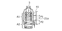
図3は、コイルばね41の周辺を拡大して示す断面図である。図3に示すように、コイルばね41は不等ピッチの巻線を有する。具体的には、コイルばね41は、その上部の第1の巻線領域A1と、それより下部の第2の巻線領域A2というように、軸線方向に2つの領域に区分されている。
FIG. 3 is an enlarged cross-sectional view showing the periphery of the
第1の巻線領域A1は、その側面が接続路21aに対向しており、巻線ピッチP1を有する。一方、第2の巻線領域A2は、その側面が接続路21aに対向しておらず、巻線ピッチP2を有し、P2>P1となっている。巻線ピッチP1,P2はそれぞれの巻線領域で個々に等しくする必要はなく、その場合には巻線ピッチP1,P2は各巻線領域での平均値をいうものとする。
The side surface of the first winding region A1 faces the connecting
本実施の形態では、弁体3が弁座20に着座した状態で、巻線ピッチP1は巻線径dに略等しく(いわゆる密着巻きと)なっているため、側面が接続路21aに対向する第1の巻線領域A1では、巻線間の隙間が略ゼロとなる。ただし、巻線ピッチP1は必ずしも巻線径dに等しい必要はなく、冷媒の通過を制限する程度に狭い隙間であれば足りる。本実施形態では、巻線間の隙間がゼロを超えた所定量である第2の巻線領域A2により、弁体3を付勢する弾性力を発揮する。なお、弁体3を付勢する弾性力は、巻線領域A1の初張力と、巻線領域A2の弾性力の和としてもよい。
In the present embodiment, when the
図2において、組み付け時には、弁体3を溶接された弁体サポート42の内側筒体42bを、コイルばね41の上端から内部へと挿入して、コイルばね41の上端を保持部42aの下面に当接させる。更に、コイルばね41の下端をばね受け部材43の外側管状部43bの内側に挿入し、底部43aの上面に当接させる。このとき、O-リング44を段部43eに取り付けておく。
In FIG. 2, at the time of assembly, the
かかる状態を保持しつつ、弁体サポート42、コイルばね41、およびばね受け部材43からなるアッセンブリを、取り付け孔2aから弁室VS内へと進入させ、雌ねじ2bに雄ねじ43cを螺合させて、不図示の工具を用いて所定位置まで追い込む。このとき、接続路21aがコイルばね41の第1の巻線領域A1の側面に正対するが、第2の巻線領域A2の側面には相対しない。ばね受け部材43は、弁本体2に装着されることにより弁室VSを封止するプラグとして機能する。
While maintaining this state, the assembly including the
本実施の形態においては、接続路21aから弁室VSに流入する冷媒の流れ方向(ここでは左右方向)に見たときに、コイルばね41の第1の巻線領域A1は、接続路21aの下端の下方に延在している。ただし、第1の巻線領域A1は接続路21aの少なくとも一部と重なっていれば足りる。
In the present embodiment, when viewed in the flow direction (here, the left-right direction) of the refrigerant flowing into the valve chamber VS from the
図1を参照して、膨張弁1の動作例について説明する。コンプレッサ101で加圧された冷媒は、コンデンサ102で液化され、膨張弁1に送られる。また、膨張弁1で断熱膨張された冷媒はエバポレータ104に送り出され、エバポレータ104で、エバポレータの周囲を流れる空気と熱交換される。エバポレータ104から戻る冷媒は、膨張弁1(より具体的には、戻り流路23)を通ってコンプレッサ101側へ戻される。
An operation example of the
膨張弁1には、コンデンサ102から高圧冷媒が供給される。より具体的には、コンデンサ102からの高圧冷媒は、第1流路21を介して弁室VSに供給される。
A high-pressure refrigerant is supplied to the
弁体3が、弁座20に着座しているとき(換言すれば、膨張弁1が閉状態のとき)には、弁室VSの上流側の第1流路21と弁室VSの下流側の第2流路22とは、非連通状態である。他方、弁体3が、弁座20から離間しているとき(換言すれば、膨張弁1が開状態のとき)には、弁室VSに供給された冷媒は、作動棒挿通孔27及び第2流路22を通って、エバポレータ104へ送り出される。なお、膨張弁1の閉状態と開状態との間の切り換えは、パワーエレメント8に接続された作動棒5によって行われる。
When the
図1の例では、パワーエレメント8は、膨張弁1の上端部に配置されている。図示していないが、パワーエレメント8の内部には、ダイアフラムにより仕切られた第1空間と第2空間とが設けられ、第1空間には作動ガスが充填されている。
In the example of FIG. 1, the
ダイアフラムの下面は、ダイアフラム支持部材を介して作動棒5に接続される。このため、第1空間内の作動ガスが液化されると、作動棒5は上方向に移動し、液化された作動ガスが気化されると、作動棒5は下方向に移動する。こうして、膨張弁1の開状態と閉状態との間の切り換えが行われる。
The lower surface of the diaphragm is connected to the
パワーエレメント8の第2空間は、戻り流路23と連通している。このため、戻り流路23を流れる冷媒の温度、圧力に応じて、第1空間内の作動ガスの相(気相、液相等)が変化し、作動棒5が駆動される。換言すれば、図1に記載の膨張弁1では、エバポレータ104から膨張弁1に戻る冷媒の温度、圧力に応じて、膨張弁1からエバポレータ104に向けて供給される冷媒の量が自動的に調整される。
The second space of the
次に、比較例を参照して、本実施形態の効果について説明する。図4は、比較例にかかる構成を示す図2と同様な断面図である。図4において、比較例のコイルばね41’は、等ピッチの巻線を有するため、コイルばね41’の巻線間の隙間δは等しくなっている。それ以外の構成は、上述した実施の形態と同様である。 Next, the effect of this embodiment will be described with reference to a comparative example. FIG. 4 is a cross-sectional view similar to FIG. 2 showing the configuration according to the comparative example. In FIG. 4, since the coil spring 41'of the comparative example has windings of equal pitch, the gaps δ between the windings of the coil spring 41'are equal. Other than that, the configuration is the same as that of the above-described embodiment.
比較例の場合、弁体3が弁座20から離間すると、第1流路21及び接続路21aから弁室VSに流入する冷媒が、図3に矢印Bで示すように、コイルばね41’の巻線間の隙間δからコイルばね41’内に進入し、反対側から抜け出るようになっている。この際に、冷媒がコイルばね41’を振動させ、それにより騒音が発生することとなる。
In the case of the comparative example, when the
これに対し、本実施形態によれば、コイルばね41の第1の巻線領域A1(図3)が接続路21aに対向しているので、図2に示すように第1流路21及び接続路21aから弁室VSに流入する冷媒が、矢印Aに示すようにコイルばね41の外周に弾かれて内部への進入を阻止されてしまい、巻線間の隙間を通過しないため、コイルばね41を振動させることがない。これにより騒音を効果的に抑制することができる。
On the other hand, according to the present embodiment, since the first winding region A1 (FIG. 3) of the
なお、本発明は、上述の実施形態に限定されない。本発明の範囲内において、上述の実施形態の任意の構成要素の変形が可能である。また、上述の実施形態において任意の構成要素の追加または省略が可能である。 The present invention is not limited to the above-described embodiment. Within the scope of the present invention, any component of the above-described embodiment can be modified. In addition, any component can be added or omitted in the above-described embodiment.
1 :膨張弁
2 :弁本体
3 :弁体
4 :付勢装置
5 :作動棒
6 :リングばね
8 :パワーエレメント
20 :弁座
21 :第1流路
22 :第2流路
23 :戻り流路
26 :環状部
27 :作動棒挿通孔
41 :コイルばね
42 :弁体サポート
43 :ばね受け部材
100 :冷媒循環システム
101 :コンプレッサ
102 :コンデンサ
104 :エバポレータ
VS :弁室
1: Expansion valve 2: Valve body 3: Valve body 4: Evaporating device 5: Actuating rod 6: Ring spring 8: Power element 20: Valve seat 21: First flow path 22: Second flow path 23: Return flow path 26: Circular portion 27: Actuating rod insertion hole 41: Coil spring 42: Valve body support 43: Spring receiving member 100: Refrigerant circulation system 101: Compressor 102: Condenser 104: Evaporator VS: Valve chamber
Claims (3)
前記弁座に着座することにより前記流体の通過を阻止し、前記弁座から離間することにより前記流体の通過を許容する弁体と、
前記供給側流路から流入する流体の流れに対して側面を向けて前記弁室に配置され、前記弁体を前記弁座に向かって付勢するコイルばねと、
前記コイルばねによる付勢力に抗して、前記弁体を前記弁座から離間する方向に押圧する作動部材と、を有し、
前記コイルばねは、前記供給側流路から流入する流体の流れに対向する第1の巻線領域と、前記第1の巻線領域とは異なる第2の巻線領域とを有し、前記第1の巻線領域における巻線間隙間は、前記第2の巻線領域における巻線間隙間より小さい、
ことを特徴とする膨張弁。 A valve body provided in a valve chamber provided between a supply-side flow path and a discharge-side flow path, and having an annular valve seat through which a fluid flowing from the supply-side flow path to the discharge-side flow path passes. ,
A valve body that blocks the passage of the fluid by sitting on the valve seat and allows the passage of the fluid by separating from the valve seat.
A coil spring arranged in the valve chamber with the side surface facing the flow of the fluid flowing from the supply side flow path and urging the valve body toward the valve seat.
It has an operating member that presses the valve body in a direction away from the valve seat against the urging force of the coil spring.
The coil spring has a first winding region facing the flow of fluid flowing from the supply-side flow path and a second winding region different from the first winding region. The interwinding clearance in the winding region of 1 is smaller than the interwinding clearance in the second winding region.
An expansion valve characterized by that.
ことを特徴とする請求項1に記載の膨張弁。 At least with the valve body seated on the valve seat, the first winding region of the coil spring has zero interwinding clearance.
The expansion valve according to claim 1.
ことを特徴とする請求項1または2に記載の膨張弁。
The coil spring has unequal pitch windings.
The expansion valve according to claim 1 or 2.
Priority Applications (1)
| Application Number | Priority Date | Filing Date | Title |
|---|---|---|---|
| JP2018051360A JP7016155B2 (en) | 2018-03-19 | 2018-03-19 | Expansion valve |
Applications Claiming Priority (1)
| Application Number | Priority Date | Filing Date | Title |
|---|---|---|---|
| JP2018051360A JP7016155B2 (en) | 2018-03-19 | 2018-03-19 | Expansion valve |
Publications (2)
| Publication Number | Publication Date |
|---|---|
| JP2019163887A JP2019163887A (en) | 2019-09-26 |
| JP7016155B2 true JP7016155B2 (en) | 2022-02-04 |
Family
ID=68066047
Family Applications (1)
| Application Number | Title | Priority Date | Filing Date |
|---|---|---|---|
| JP2018051360A Active JP7016155B2 (en) | 2018-03-19 | 2018-03-19 | Expansion valve |
Country Status (1)
| Country | Link |
|---|---|
| JP (1) | JP7016155B2 (en) |
Citations (3)
| Publication number | Priority date | Publication date | Assignee | Title |
|---|---|---|---|---|
| JP2008180475A (en) | 2007-01-26 | 2008-08-07 | Fuji Koki Corp | Expansion valve |
| JP2013257064A (en) | 2012-06-12 | 2013-12-26 | Fuji Koki Corp | Expansion valve |
| JP6182363B2 (en) | 2013-06-07 | 2017-08-16 | 株式会社不二工機 | Expansion valve |
Family Cites Families (1)
| Publication number | Priority date | Publication date | Assignee | Title |
|---|---|---|---|---|
| JPH036173U (en) * | 1989-06-06 | 1991-01-22 |
-
2018
- 2018-03-19 JP JP2018051360A patent/JP7016155B2/en active Active
Patent Citations (3)
| Publication number | Priority date | Publication date | Assignee | Title |
|---|---|---|---|---|
| JP2008180475A (en) | 2007-01-26 | 2008-08-07 | Fuji Koki Corp | Expansion valve |
| JP2013257064A (en) | 2012-06-12 | 2013-12-26 | Fuji Koki Corp | Expansion valve |
| JP6182363B2 (en) | 2013-06-07 | 2017-08-16 | 株式会社不二工機 | Expansion valve |
Also Published As
| Publication number | Publication date |
|---|---|
| JP2019163887A (en) | 2019-09-26 |
Similar Documents
| Publication | Publication Date | Title |
|---|---|---|
| US20130283836A1 (en) | Expansion valve and vibration-proof spring | |
| JP6367164B2 (en) | Pressure operated valve and refrigeration cycle | |
| JP2006242413A (en) | Constant flow rate expansion valve | |
| US8267329B2 (en) | Expansion valve with noise reduction means | |
| JP2017026191A (en) | Temperature expansion valve and refrigeration cycle | |
| JP4848548B2 (en) | Expansion valve with solenoid valve | |
| JP7074322B2 (en) | Expansion valve | |
| JP7016155B2 (en) | Expansion valve | |
| JP7074321B2 (en) | Expansion valve | |
| JP7082798B2 (en) | Expansion valve | |
| JP7089769B2 (en) | Expansion valve | |
| WO2019181377A1 (en) | Expansion valve | |
| CN111133240B (en) | Expansion valve | |
| JP2019163834A (en) | Expansion valve | |
| JP2019158296A (en) | Expansion valve | |
| JP2017187225A (en) | Expansion valve | |
| JP2006132881A (en) | Expansion valve | |
| JP2011133157A (en) | Expansion valve | |
| JP7153911B2 (en) | expansion valve | |
| JP7153912B2 (en) | expansion valve | |
| JP7373857B2 (en) | Power element and expansion valve using it | |
| JP7366401B2 (en) | Power element and expansion valve using it | |
| WO2021106933A1 (en) | Power element and expansion valve using same | |
| JP7262261B2 (en) | THERMAL EXPANSION VALVE AND REFRIGERATION CYCLE SYSTEM USING THERMAL EXPANSION VALVE | |
| JP2018035866A (en) | Expansion valve |
Legal Events
| Date | Code | Title | Description |
|---|---|---|---|
| A621 | Written request for application examination |
Free format text: JAPANESE INTERMEDIATE CODE: A621 Effective date: 20210125 |
|
| TRDD | Decision of grant or rejection written | ||
| A977 | Report on retrieval |
Free format text: JAPANESE INTERMEDIATE CODE: A971007 Effective date: 20211215 |
|
| A01 | Written decision to grant a patent or to grant a registration (utility model) |
Free format text: JAPANESE INTERMEDIATE CODE: A01 Effective date: 20211221 |
|
| A61 | First payment of annual fees (during grant procedure) |
Free format text: JAPANESE INTERMEDIATE CODE: A61 Effective date: 20220118 |