JP7012342B2 - Pachinko machine - Google Patents
Pachinko machine Download PDFInfo
- Publication number
- JP7012342B2 JP7012342B2 JP2017185896A JP2017185896A JP7012342B2 JP 7012342 B2 JP7012342 B2 JP 7012342B2 JP 2017185896 A JP2017185896 A JP 2017185896A JP 2017185896 A JP2017185896 A JP 2017185896A JP 7012342 B2 JP7012342 B2 JP 7012342B2
- Authority
- JP
- Japan
- Prior art keywords
- light
- light source
- reflecting portion
- decorative member
- optical axis
- Prior art date
- Legal status (The legal status is an assumption and is not a legal conclusion. Google has not performed a legal analysis and makes no representation as to the accuracy of the status listed.)
- Active
Links
Images


Landscapes
- Pinball Game Machines (AREA)
Description
本発明は、遊技機に関する。 The present invention relates to a gaming machine.
光源から出射された光により照らされる装飾部材を備えた遊技機が種々知られている(例えば、下記特許文献1参照)。
Various gaming machines provided with decorative members illuminated by light emitted from a light source are known (see, for example,
本発明は、光源および当該光源の光に照らされる装飾部材を備えた遊技機において、当該装飾部材の装飾性を高めることを目的とする。 An object of the present invention is to enhance the decorativeness of the decorative member in a gaming machine provided with a light source and a decorative member illuminated by the light of the light source.
上記課題を解決するためになされた本発明にかかる遊技機は、光軸が前後方向に直交する平面に略沿うように配置された光源と、前記光源の光軸に交差するように当該光源の光出射側に配置された部材であって、前記光源から出射された光を透過させる空間または無色透明な材料で形成された光透過部および光を反射させる光反射部が形成された装飾部材と、を備えることを特徴とする。 The gaming machine according to the present invention, which has been made to solve the above problems, has a light source arranged so as to substantially follow a plane whose optical axis is orthogonal to the front-rear direction, and the light source so as to intersect the optical axis of the light source. A member arranged on the light emitting side, which is a space for transmitting light emitted from the light source or a decorative member having a light transmitting portion made of a colorless and transparent material and a light reflecting portion for reflecting light. , Is characterized by the provision of.
本発明にかかる遊技機によれば、光源の光に照らされる装飾部材の装飾性を高めることが可能である。 According to the gaming machine according to the present invention, it is possible to enhance the decorativeness of the decorative member illuminated by the light of the light source.
以下、本発明にかかる遊技機1の一実施形態について図面を参照して詳細に説明する。まず、図1を参照して遊技機1の全体構成について簡単に説明する。
Hereinafter, an embodiment of the
遊技機1は遊技盤90を備える。遊技盤90は、ほぼ正方形の合板により成形されており、発射装置908(発射ハンドル)の操作によって発射された遊技球を遊技領域902に案内する通路を構成するガイドレール903が略円弧形状となるように設けられている。
The
遊技領域902には、表示装置91、始動入賞口904、大入賞口906、アウト口などが設けられている。かかる表示装置91の表示領域911は、遊技盤90に形成された開口901を通じて視認可能となる領域である。なお、表示領域911の形状等は適宜変更可能である(開口901の形状や大きさ、表示装置91自体の形状や大きさを変更することで表示領域911の形状等を変更することができる)。
The
また、遊技領域902には、流下する遊技球が衝突することにより遊技球の流下態様に変化を与える障害物としての遊技釘が複数設けられている。遊技領域902を流下する遊技球は、遊技釘に衝突したときの条件に応じて様々な態様に変化する。
Further, in the
このような遊技機1では、発射装置908を操作することにより遊技領域902に向けて遊技球を発射する。遊技領域902を流下する遊技球が、始動入賞口904や大入賞口906等の入賞口に入賞すると、所定の数の賞球が払出装置により払い出される。
In such a
大当たりの抽選は、図示されない制御基板21に設けられた当否判定手段が始動入賞口904への遊技球の入賞を契機として実行する(このような始動入賞口は複数設けられていてもよい)。具体的には、始動入賞口904への遊技球の入賞を契機として乱数源から数値(以下、当否判定情報と称することもある)が取得され、当該数値が予め定められた大当たりの数値と同じである場合には大当たりとなり、異なる場合にははずれとなる。
The jackpot lottery is executed by the winning / failing determination means provided on the control board 21 (not shown) triggered by the winning of the game ball to the starting winning opening 904 (a plurality of such starting winning openings may be provided). Specifically, a numerical value (hereinafter, also referred to as hit / fail judgment information) is acquired from a random number source triggered by the winning of the game ball to the
本実施形態では、公知の遊技機と同様に、表示装置91の表示領域911に表示される装飾図柄50(図1等参照)の組み合わせによって当否判定結果を遊技者に報知する。装飾図柄50は、当否判定結果の報知の開始とともに変動を開始する。大当たりに当選している場合には装飾図柄50は最終的に所定の組み合わせ(例えば、同じ装飾図柄50の三つ揃い)で停止する。はずれである場合には装飾図柄50は最終的にそれ以外(大当たりとなる組み合わせ以外)の組み合わせで停止する。
In the present embodiment, similarly to the known gaming machine, the winning / failing determination result is notified to the player by the combination of the decorative symbols 50 (see FIG. 1 and the like) displayed in the
なお、遊技機1の枠体、遊技球を貯留する下皿や上皿など、本発明に関係のない遊技機1の構成要素は説明を省略する。これらについては公知の遊技機と同様の構造のものが適用できる。
The components of the
以下、本実施形態にかかる遊技機1が備える装飾ユニット10について詳細に説明する。なお、以下の説明では、遊技盤面に直交する方向を前後方向(遊技者側を前とする)と、重力方向を上下方向と、前後方向および上下方向に直交する方向を横方向(左右方向、幅方向)と規定する。各図において、前後方向はY軸、上下方向はZ軸、横方向はX軸に沿う方向である。
Hereinafter, the
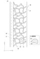
本実施形態における装飾ユニット10(図1、図2、図3(a)参照)は、遊技機1の本体部分に固定されたものであって、光源20、装飾部材30、および反射部材40を備える。本実施形態における装飾ユニット10は、遊技領域902の左側に設けられている(なお、図1は、装飾ユニット10以外の構成はどのようなものであってもよいため、装飾ユニット10以外の装飾等は省略している)。
The decorative unit 10 (see FIGS. 1, 2, and 3 (a)) in the present embodiment is fixed to the main body of the
本実施形態における光源20はLEDであり、当該光源20を制御する回路の少なくとも一部が構築された基板(以下、制御基板21と称する)に実装されている(図2、図3(a)参照)。制御基板21は横方向に直交する平面(YZ平面)方向に沿うように配置されている。本実施形態における制御基板21は、上下方向に細長い形状を呈する。かかる制御基板21において、上下方向に並ぶように複数の光源20が実装されている。当該複数の光源20の前後方向における位置は同じである。各光源20は、その光軸Lが横方向に沿うように配置されている。上述したように、本実施形態における装飾ユニット10は、遊技領域の左側に設けられているところ、光源20は右方、すなわち幅方向中央に向かって光を出射させるように設けられている。
The
装飾部材30は、実際に装飾機能を発現する部材であって、光源20の光出射側に設けられている(図2、図3(a)参照)。つまり、本実施形態では、光源20の右方に配置されている。装飾部材30は、光透過部31および光反射部32を有する。具体的には、装飾部材30は、細長い線状の部分が入り組んだ網目状の構造を有する。当該線状の部分の表面が光反射部32として、線状の部分の間が光透過部31として機能する。光反射部32の表面は鏡面である。当該鏡面を構築する手法はどのようなものであってもよい。例えば、蒸着によって金属を付着させることで当該鏡面を構築することができる。光透過部31(線状の部分)の間は空間となっている。したがって、光透過部31に到達した光はそのまま当該光透過部31を通過する。なお、光透過部31は、空間ではなく、光透過性を有する材料(無色透明であることが好ましい)で形成された部分としてもよい。
The
光反射部32(線状の部分)は、その前側が前側光反射部321として、後側が後側光反射部322として機能する。前側光反射部321は、遊技者に直接的に視認される部分であるといえる。後側光反射部322は、詳細を後述する反射部材40によって反射されることで遊技者に間接的に視認される部分であるといえる。前側光反射部321と後側光反射部322の鏡面処理の態様は同じであってもよいし、異なっていてもよい。異なるものとするのであれば、前側光反射部321は遊技者に直接視認される部分であって後側光反射部322に比して「目立つ」ものであるといえるため、前側光反射部321の方が後側光反射部322よりも光沢度が高いものとするとよい。光反射部32(線状の部分)を断面で見ると、前側光反射部321は前方に向かって凸となるような湾曲した面であり、後側光反射部322は平坦に近い面となっている(図2の枠囲み部分参照)。
The front side of the light reflecting portion 32 (linear portion) functions as a front
本実施形態における装飾部材30は、全体として、光源20から離れるにつれて後方に向かうような形状を呈する(図3(a)参照)。つまり、上下方向に直交する平面で切断した断面で考えると、光源20に近い側(左端)が前方に位置し、光源20に遠い側(右端)が後方に位置するような形状を呈する。装飾部材30の全部ではなく、一部がこのような形状を呈する部分であるものとしてもよい。光源20の光軸Lは、装飾部材30の左端よりも後方、かつ装飾部材30の右端よりも前方に位置している。つまり、装飾部材30は、光源20の光軸Lと交差するように配置されている。
As a whole, the
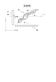
反射部材40は、その前面に形成された反射面41(鏡面)を有する部材である(図2、図3(a)参照)。当該反射面41は、前後方向に直交する平面に沿う。当該反射部材40は、前後方向において、その少なくとも一部が装飾部材30と重なるように配置されている。反射部材40よりも前に配置された装飾部材30は光透過部31を有するため、遊技者は、当該光透過部31を通じて反射部材40の反射面41に映し出された像を視認することができる。また、反射部材40(反射面41)は、光源20の光軸Lよりも後方に位置する。したがって、光源20が設けられた側(装飾ユニット10の左側)でみれば、前から、装飾部材30、光源20、反射部材40の順で位置することになる。
The
このように構成される装飾ユニット10の作用は以下の通りである。光源20を駆動すると、当該光源20から右方向、すなわち装飾部材30側に向かう光が出射される。装飾部材30に到達した光のうち、光透過部31を通過した光の一部は、前側光反射部321に反射される(図3(b)参照)。つまり、遊技者に直接的に視認される前側光反射部321が、光に照らされることになって装飾が煌びやかなものとなる。
The operation of the
一方、後側光反射部322に到達した光は、当該後側光反射部322に反射され、その光がさらに反射部材40の反射面41で反射されることとなる(図3(b)参照)。つまり、後側光反射部322も光源20からの光に照らされて、それが反射部材40によって反射されることで遊技者に視認される(光透過部31を通じて視認される)ことになる。
On the other hand, the light that has reached the rear
このように、本実施形態では、装飾部材30の光反射部32は、光源20の光によって照らされることになるところ、前側光反射部321については、光の一部が光透過部31を通過することによって照らされたものが直接的に遊技者に視認される一方、後側光反射部322については光の一部によって照らされたものが反射部材40を介して間接的に遊技者に視認されることになる。これらが相まって、煌びやかな装飾部材30が立体的(三次元的)に視認されることとなる。
As described above, in the present embodiment, the
特に本実施形態における前側光反射部321は、前方に向かって凸となるような面としている。したがって、光軸Lが横方向である光源20から出射された光の多くは、前側光反射部321に反射されて前方に向かうことになる。つまり、前側光反射部321を上記のような形状とすることにより、遊技者側に向かう光量が多くなるため、装飾部材30がより煌びやかに輝いているようにみえる。なお、後側光反射部322は、基本的には反射部材40に反射されることで視認される部分(あくまで直接的に視認される前側光反射部321を補助する部分)であるため、前側光反射部321のような形状とはしていない。本実施形態では、装飾部材30全体が光源20から離れるにつれて後方に向かうような形状を呈しているため、後側光反射部322に到達した光の多くは、反射部材40側に反射されることになる。つまり、装飾部材30全体の形状を上記のようなものとすることで、反射部材40を介して視認される後側光反射部322も煌びやかに輝いているように見えることになる。
In particular, the front
また、本実施形態における装飾ユニット10は、遊技機1の側方(本実施形態では左側)に設けられており、装飾部材30は幅方向外側から中央に向かって後方に向かうような形状を呈する。また、反射部材40(反射面41)は、前後方向に直交する平面方向に沿う。したがって、遊技者視点(遊技機1の中央に対して遊技者が正対すると仮定した場合の視点)では、前側光反射部321の一部についても、反射部材40に反射されることで間接的に遊技者に視認されることになる。つまり、後側光反射部322だけでなく、前側光反射部321も反射部材40に反射されて視認されることになるため、光に照らされた装飾部材30が幾重にも重なっているかのように視認される。
Further, the
以下、上記実施形態にかかる遊技機1を改良、変形、具体化等した具体例について説明する。なお、以下の各具体例を用いて説明する事項を複数適用した構成としてもよい。
Hereinafter, specific examples in which the
○第一具体例
反射部材40が設けられていない構成としてもよい。上述したように、反射部材40は、装飾部材30の後側光反射部322を映し出す作用をもたらすものであるが、このような反射部材40がなくても、従来にない斬新な装飾態様を実現することができる。つまり、横方向に光を出射する光源20の光軸Lに対し、光透過部31および光反射部32(前側光反射部321)が形成された装飾部材30が交差するように設けられた構造であるから、光透過部31を通過した光により遊技者側に位置する前側光反射部321が照らされるという従来にない装飾態様が発現されることとなる。
○ First Specific Example A configuration may be configured in which the
○第二具体例
上記実施形態における装飾ユニット10は、上下方向に並ぶ(前後方向における位置が同じである)複数の光源20が設けられていることを説明したが、前後方向における位置が異なるように光源20が配置された構成とする(図4参照)。例えば、一または複数の第一光源201と、当該第一光源201よりも後方に位置する一または複数の第二光源202が設けられた構成とする。複数の第一光源201を設ける場合、当該第一光源201は上下方向に沿って並ぶものとする。同様に、複数の第二光源202を設ける場合、当該第二光源202は上下方向に沿って並ぶものとする。かかる第一光源201の光軸L1および第二光源202の光軸L2の両方に交差するようにして、装飾部材30が設けられる。
○ Second Specific Example It has been explained that the
このようにすることで、装飾部材30に到達する光が様々な方向に行きかう状態となるから、装飾部材30による装飾性がさらに高められる。また、装飾部材30を照らす光量のムラを低減することが可能である。
By doing so, the light reaching the
なお、前後方向における位置が異なる三種以上の光源20を設けた構成(第一光源201および第二光源202に加えて、両光源と前後方向位置が異なる別の光源を設けた構成)としてもよい。このような構成とする場合においても、全ての光源20の光軸Lが装飾部材30と重なるようにするとよい。
In addition, a configuration in which three or more types of
○第三具体例
上記実施形態における光源20の光軸Lは横方向に沿うものであることを説明したが、光軸Lが横方向に対して傾いて設定された構成としてもよい。ただし、このような構成とする場合であっても、光軸Lは装飾部材30と交差するようにする。なお、光軸Lが横方向(X軸)に対して傾斜する角度(光軸LとX軸が形成する角度)が45度未満となるように光源20が配置されている場合には、当該光源20の光軸Lは略横方向に沿うものとする。
○ Third Specific Example Although it has been explained that the optical axis L of the
上下方向から見て、光軸Lが横方向に対して前側(遊技者側)に傾いて設定された構成(図5(a)参照)とすれば、前側光反射部321に到達する光量が多くなる。つまり、前側光反射部321の輝き(直接的に視認される装飾)がより強調される装飾態様となる。一方、光軸Lが横方向に対して後側に傾いて設定された構成(図5(b)参照)とすれば、後側光反射部322に到達する光量が多くなる。つまり、後側光反射部322の輝き(反射部材40を介して間接的に視認される装飾)がより強調される装飾態様となる。このように、光源20の光軸Lを傾けることにより、前側光反射部321および後側光反射部322の一方を他方に比して強調させる装飾態様を実現することが可能となる。当該強調の度合は、光軸Lの傾きが大きくなるほど高くなる。
Assuming that the optical axis L is set to be tilted to the front side (player side) with respect to the lateral direction when viewed from the vertical direction (see FIG. 5A), the amount of light reaching the front side
なお、光源20の光軸Lが略横方向に沿う構成はあくまで一例である。光源20の光軸Lは、前後方向に直交する面方向(XZ平面)に略沿うものであればよい。つまり、光軸Lは、当該面方向に沿って見て、当該面に対して傾斜する角度(当該面と光軸が形成する角度)が45度未満となるように設定されたものであればよい。このように光源20が配置された構成であれば、光軸Lは上記面方向に略沿うものとする。装飾部材30は、光源20の光出射側かつ光軸Lと交差するように配置されていればよい。
It should be noted that the configuration in which the optical axis L of the
○第四具体例
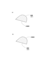
上記実施形態における装飾部材30は、光源20から離れるにつれて後方に向かうような形状を呈するものであることを説明したが、光源20から離れるにつれて前方に向かうような形状を呈するものとしてもよい(図6参照)。このような構成としても、一部の光は前側光反射部321に反射され、他の一部の光は後側光反射部322に反射されるから、立体的な装飾態様を実現することができる。
○ Fourth Specific Example Although it has been explained that the
ただし、本例のような構成とした場合、前側光反射部321が光源20側に位置している構造となるから、上記実施形態と比べて、前側光反射部321によって反射される光量が増加し、後側光反射部322によって反射される光量が低下することになる。つまり、上記実施形態に比して前側光反射部321の輝きが強調される構成となるといえる。
However, in the case of the configuration as in this example, since the front
○第五具体例
上記実施形態における装飾部材30は、光反射部32は、前側光反射部321および後側光反射部322を含むものであること、すなわち線状の部分(光透過部31を除いた有体物である部分)の表面全体が光反射部32(鏡面)であることを説明したが、一部のみが光反射部32とされた構成としてもよい。
Fifth Specific Example In the
例えば、線状の部分の前側は鏡面処理が施された光反射部32(前側光反射部321)とされるものの、後側は光反射部32ではない(鏡面処理が施されていない)構成としてもよい(図7(a)参照)。このような構成としても、前側光反射部321は、光透過部31を通過した光によって照らされる構成となる。また、線状の部分の後側についても、反射部材40によって反射されることにより遊技者に視認されることになる。
For example, the front side of the linear portion is a light reflecting portion 32 (front side light reflecting portion 321) that has been mirror-finished, but the rear side is not a light reflecting portion 32 (not mirror-finished). (See FIG. 7 (a)). Even with such a configuration, the front
これとは逆に、線状の部分の後側は鏡面処理が施された光反射部32(後側光反射部322)とされるものの、前側は光反射部32ではない(鏡面処理が施されていない)構成としてもよい(図7(b)参照)。このような構成としても、光源20の光に照らされた後側光反射部322は、反射部材40を介して遊技者に視認されることになる。また、線状の部分の前側は、そのまま遊技者に視認されることになる。
On the contrary, the rear side of the linear portion is a light reflecting portion 32 (rear side light reflecting portion 322) that has been mirror-finished, but the front side is not the light reflecting portion 32 (mirror-finished). It may be configured (see FIG. 7 (b)). Even with such a configuration, the rear
○第六具体例
光源20と装飾部材30との間に一または複数の光学レンズ22を介在させてもよい(図8参照)。つまり、光源20から出射された光を構成する光線が光学レンズ22の作用によってその進行方向が変化させられた上で、装飾部材30に到達するような構成としてもよい。当該光学レンズ22として採用するレンズの態様(種類)により、装飾部材30による装飾態様が種々変化することになる。
○ Sixth Specific Example One or more
○第七具体例
上記実施形態における装飾ユニット10は、遊技機1の本体側に動かないように固定されたものであるが、可動体(いわゆる役物)の装飾について、上記装飾ユニット10に用いた技術と同様の技術を適用してもよい。
○ Seventh Specific Example The
以上、本発明の実施の形態について詳細に説明したが、本発明は上記実施の形態に何ら限定されるものではなく、本発明の要旨を逸脱しない範囲で種々の改変が可能である。 Although the embodiments of the present invention have been described in detail above, the present invention is not limited to the above embodiments, and various modifications can be made without departing from the gist of the present invention.
上記実施形態にかかる遊技機1は、いわゆるぱちんこ遊技機であるが、回動式遊技機等のその他の遊技機に対しても同様の技術思想が適用可能である。
The
上記実施形態から得られる具体的手段(遊技機)を以下に列挙する。 Specific means (game machines) obtained from the above embodiments are listed below.
・手段1
光軸が略横方向に沿うように配置された光源と、
前記光源の光軸に交差するように当該光源の光出射側に配置された部材であって、前記光源から出射された光を透過させる光透過部および光を反射させる光反射部が形成された装飾部材と、
を備えることを特徴とする遊技機。
上記遊技機によれば、装飾部材は、光源から横方向に向かって出射された光を透過させる光透過部と反射させる光反射部を有しているため、当該装飾部材による装飾態様が斬新なものとなる。
・ Means 1
A light source whose optical axis is arranged so as to run substantially in the horizontal direction,
A member arranged on the light emitting side of the light source so as to intersect the optical axis of the light source, and a light transmitting portion for transmitting the light emitted from the light source and a light reflecting portion for reflecting the light are formed. Decorative materials and
A gaming machine characterized by being equipped with.
According to the above-mentioned gaming machine, since the decorative member has a light transmitting portion that transmits light emitted laterally from the light source and a light reflecting portion that reflects the light, the decoration mode by the decorative member is novel. It becomes a thing.
・手段2
前記装飾部材の後方には、前後方向において少なくとも一部が前記装飾部材と重なる反射部材が設けられていることを特徴とする手段1に記載の遊技機。
このようにすれば、装飾部材の光反射部によって反射された光の一部が反射部材に反射されることになるから、装飾部材による装飾が立体感のあるものとなる。
・ Means 2
The gaming machine according to
By doing so, a part of the light reflected by the light reflecting portion of the decorative member is reflected by the reflecting member, so that the decoration by the decorative member has a three-dimensional effect.
・手段3
前記装飾部材の前側には、前記光源から出射されて前記光透過部を透過した光を反射させる前記光反射部の少なくとも一部である前側光反射部が形成されていることを特徴とする手段1または手段2に記載の遊技機。
このように、装飾部材の装飾性を向上させるため、光透過部を透過した光を反射させる前側光反射部が設けられているとよい。
・ Means 3
A means characterized in that a front light reflecting portion, which is at least a part of the light reflecting portion, is formed on the front side of the decorative member to reflect light emitted from the light source and transmitted through the light transmitting portion. The gaming machine according to 1 or means 2.
As described above, in order to improve the decorativeness of the decorative member, it is preferable to provide a front light reflecting portion that reflects the light transmitted through the light transmitting portion.
・手段4
前記装飾部材の後側には、前記光源から出射された光を反射させる前記光反射部の少なくとも一部である後側光反射部が形成されていることを特徴とする手段1から手段3のいずれかに記載の遊技機。
このように、装飾部材の装飾性を向上させるため、光源から出射された光を反射させる後側光反射部が設けられているとよい。上述した反射部材が設けられている場合、後側光反射部に反射された光の一部は、当該反射部材に反射されることになるから、装飾の立体感がさらに高められる。
・ Means 4
The
As described above, in order to improve the decorativeness of the decorative member, it is preferable to provide a rear light reflecting portion that reflects the light emitted from the light source. When the above-mentioned reflecting member is provided, a part of the light reflected by the rear light reflecting portion is reflected by the reflecting member, so that the three-dimensional effect of the decoration is further enhanced.
・手段5
前記光源として、第一光源および当該第一光源よりも後方に位置する第二光源が設けられ、
前記装飾部材は、前記第一光源の光軸および前記第二光源の光軸の両方に交差するように設けられていることを特徴とする手段1から手段4のいずれかに記載の遊技機。
このようにすることで、装飾部材に到達する光が様々な方向に行きかう状態となるから、装飾部材による装飾性がさらに高められる。また、装飾部材を照らす光量のムラを低減することが可能である。
・ Means 5
As the light source, a first light source and a second light source located behind the first light source are provided.
The gaming machine according to any one of
By doing so, the light that reaches the decorative member travels in various directions, so that the decorativeness of the decorative member is further enhanced. In addition, it is possible to reduce unevenness in the amount of light that illuminates the decorative member.
・手段6
前記装飾部材は、前記光源から離れるにつれて後方に向かうような形状を呈する部分を含むことを特徴とする手段1から手段5のいずれかに記載の遊技機。
このような構成とすることで、光透過部を通過して装飾部材の前面に到達する光と、装飾部材の後面に到達する光が存在するような光の照射態様となるため、光に照らされる装飾部材がより立体感のあるものとなる。
・ Means 6
The gaming machine according to any one of
With such a configuration, the light is irradiated so that the light that passes through the light transmitting portion and reaches the front surface of the decorative member and the light that reaches the rear surface of the decorative member are present. The decorative members are more three-dimensional.
1 遊技機
10 装飾ユニット
20 光源
L 光軸
30 装飾部材
31 光透過部
32 光反射部
321 前側光反射部
322 後側光反射部
40 反射部材
41 反射面
1
Claims (1)
一部が前記光軸よりも前方に、その他の部分が前記光軸よりも後方に位置して、前記光源から離れるにつれて後方に向かうような形状を呈し、前記光源の光軸に交差するように当該光源の光出射側に配置された部材であって、前記光源から出射された光を透過させる空間または無色透明な材料で形成された光透過部および光を反射させる光反射部が形成された装飾部材と、
を備え、
前記装飾部材は、前方から見て前記光反射部が存在する箇所以外の箇所に前記光透過部が存在するように形成されたものであることを特徴とする遊技機。 A light source arranged so that the optical axis is substantially along a plane orthogonal to the front-back direction,
A part is located in front of the optical axis and the other part is located behind the optical axis so as to be shaped so as to move backward as the distance from the light source increases and intersect the optical axis of the light source. A member arranged on the light emitting side of the light source, in which a space for transmitting light emitted from the light source or a light transmitting portion made of a colorless transparent material and a light reflecting portion for reflecting light are formed. Decorative materials and
Equipped with
The gaming machine is characterized in that the decorative member is formed so that the light transmitting portion exists in a place other than the place where the light reflecting portion exists when viewed from the front .
Priority Applications (1)
| Application Number | Priority Date | Filing Date | Title |
|---|---|---|---|
| JP2017185896A JP7012342B2 (en) | 2017-09-27 | 2017-09-27 | Pachinko machine |
Applications Claiming Priority (1)
| Application Number | Priority Date | Filing Date | Title |
|---|---|---|---|
| JP2017185896A JP7012342B2 (en) | 2017-09-27 | 2017-09-27 | Pachinko machine |
Publications (3)
| Publication Number | Publication Date |
|---|---|
| JP2019058396A JP2019058396A (en) | 2019-04-18 |
| JP2019058396A5 JP2019058396A5 (en) | 2020-11-12 |
| JP7012342B2 true JP7012342B2 (en) | 2022-02-14 |
Family
ID=66178298
Family Applications (1)
| Application Number | Title | Priority Date | Filing Date |
|---|---|---|---|
| JP2017185896A Active JP7012342B2 (en) | 2017-09-27 | 2017-09-27 | Pachinko machine |
Country Status (1)
| Country | Link |
|---|---|
| JP (1) | JP7012342B2 (en) |
Citations (6)
| Publication number | Priority date | Publication date | Assignee | Title |
|---|---|---|---|---|
| JP2009219658A (en) | 2008-03-17 | 2009-10-01 | Miyama Denki Kk | Illumination type press switch for game machine |
| JP2011015891A (en) | 2009-07-10 | 2011-01-27 | Sophia Co Ltd | Game machine |
| JP2012011004A (en) | 2010-06-30 | 2012-01-19 | Newgin Co Ltd | Game machine |
| JP2012245334A (en) | 2011-05-31 | 2012-12-13 | Okumura Yu-Ki Co Ltd | Game machine |
| JP2013169260A (en) | 2012-02-20 | 2013-09-02 | Okumura Yu-Ki Co Ltd | Pachinko game machine |
| JP2014033694A (en) | 2012-08-07 | 2014-02-24 | Sophia Co Ltd | Game machine |
-
2017
- 2017-09-27 JP JP2017185896A patent/JP7012342B2/en active Active
Patent Citations (6)
| Publication number | Priority date | Publication date | Assignee | Title |
|---|---|---|---|---|
| JP2009219658A (en) | 2008-03-17 | 2009-10-01 | Miyama Denki Kk | Illumination type press switch for game machine |
| JP2011015891A (en) | 2009-07-10 | 2011-01-27 | Sophia Co Ltd | Game machine |
| JP2012011004A (en) | 2010-06-30 | 2012-01-19 | Newgin Co Ltd | Game machine |
| JP2012245334A (en) | 2011-05-31 | 2012-12-13 | Okumura Yu-Ki Co Ltd | Game machine |
| JP2013169260A (en) | 2012-02-20 | 2013-09-02 | Okumura Yu-Ki Co Ltd | Pachinko game machine |
| JP2014033694A (en) | 2012-08-07 | 2014-02-24 | Sophia Co Ltd | Game machine |
Also Published As
| Publication number | Publication date |
|---|---|
| JP2019058396A (en) | 2019-04-18 |
Similar Documents
| Publication | Publication Date | Title |
|---|---|---|
| JP2014212947A (en) | Game machine | |
| JP2019205502A (en) | Game machine | |
| JP2019141398A (en) | Game machine | |
| JP7012342B2 (en) | Pachinko machine | |
| JP2019180992A (en) | Game machine | |
| JP6041316B2 (en) | Game machine | |
| JP2019141397A (en) | Game machine | |
| JP6127352B2 (en) | Game machine | |
| JP7224611B2 (en) | game machine | |
| JP6262970B2 (en) | Directing equipment | |
| JP2020068816A (en) | Game machine | |
| JP2019180739A (en) | Game machine | |
| JP5802905B2 (en) | Game machine | |
| JP2019058471A (en) | Game machine | |
| JP2014212949A (en) | Game machine | |
| JP2014212948A (en) | Game machine | |
| JP6226346B2 (en) | Game machine | |
| JP6236034B2 (en) | Game machine | |
| JP6998583B2 (en) | Pachinko machine | |
| JP6019349B2 (en) | Game machine | |
| JP2019141396A (en) | Game machine | |
| JP5762464B2 (en) | Game machine | |
| JP7131790B2 (en) | game machine | |
| JP6156892B2 (en) | Game machine | |
| JP6236033B2 (en) | Game machine |
Legal Events
| Date | Code | Title | Description |
|---|---|---|---|
| A521 | Request for written amendment filed |
Free format text: JAPANESE INTERMEDIATE CODE: A523 Effective date: 20200925 |
|
| A621 | Written request for application examination |
Free format text: JAPANESE INTERMEDIATE CODE: A621 Effective date: 20200925 |
|
| A977 | Report on retrieval |
Free format text: JAPANESE INTERMEDIATE CODE: A971007 Effective date: 20210727 |
|
| A131 | Notification of reasons for refusal |
Free format text: JAPANESE INTERMEDIATE CODE: A131 Effective date: 20210810 |
|
| A521 | Request for written amendment filed |
Free format text: JAPANESE INTERMEDIATE CODE: A523 Effective date: 20210927 |
|
| TRDD | Decision of grant or rejection written | ||
| A01 | Written decision to grant a patent or to grant a registration (utility model) |
Free format text: JAPANESE INTERMEDIATE CODE: A01 Effective date: 20211214 |
|
| A61 | First payment of annual fees (during grant procedure) |
Free format text: JAPANESE INTERMEDIATE CODE: A61 Effective date: 20220111 |
|
| R150 | Certificate of patent or registration of utility model |
Ref document number: 7012342 Country of ref document: JP Free format text: JAPANESE INTERMEDIATE CODE: R150 |