JP7009230B2 - Non-destructive inspection equipment and non-destructive inspection method - Google Patents
Non-destructive inspection equipment and non-destructive inspection method Download PDFInfo
- Publication number
- JP7009230B2 JP7009230B2 JP2018009071A JP2018009071A JP7009230B2 JP 7009230 B2 JP7009230 B2 JP 7009230B2 JP 2018009071 A JP2018009071 A JP 2018009071A JP 2018009071 A JP2018009071 A JP 2018009071A JP 7009230 B2 JP7009230 B2 JP 7009230B2
- Authority
- JP
- Japan
- Prior art keywords
- detector
- rays
- subject
- ray source
- destructive inspection
- Prior art date
- Legal status (The legal status is an assumption and is not a legal conclusion. Google has not performed a legal analysis and makes no representation as to the accuracy of the status listed.)
- Active
Links
- PAFZNILMFXTMIY-UHFFFAOYSA-N NC1CCCCC1 Chemical compound NC1CCCCC1 PAFZNILMFXTMIY-UHFFFAOYSA-N 0.000 description 1
Images


Description
本発明は、後方散乱X線を検出することにより内部構造を破壊することなく検査する非破壊検査装置及び非破壊検査方法に関し、特に、例えば、エスカレータのハンドレール、配管の亀裂、ジョイント部のずれ、または、壁若しくは床面の探傷に関して一方向から内部を検査する技術に関する非破壊検査装置に適用して好適なものである。 The present invention relates to a non-destructive inspection device and a non-destructive inspection method for inspecting an internal structure without destroying the internal structure by detecting backward scattered X-rays, and in particular, for example, a handrail of an escalator, a crack in a pipe, and a displacement of a joint portion. Or, it is suitable for application to a non-destructive inspection device relating to a technique for inspecting the inside from one direction with respect to flaw detection of a wall or floor surface.
従来より、内部構造を非破壊で検査するニーズは大きく、医療及び工業分野において超音波、磁気、レーザ、赤外線、X線など様々な電磁波を用いたX線検査技術が開発されている。これらのうちX線を用いた検査(以下「X線検査」という)は、リアルタイムで高精細な画像を得ることができることから、医療分野では救急対応及び治療支援に用いられている。近年、カテーテル手術及び内視鏡手術の普及に伴い、その利用の場が拡大している。工業分野においても、被写体の状態を保ったまま異常及び劣化を動画または断面像によって観察可能であるため、X線検査は製品の品質管理において重要な役割を担っている。 Conventionally, there is a great need for non-destructive inspection of internal structures, and X-ray inspection techniques using various electromagnetic waves such as ultrasonic waves, magnetism, lasers, infrared rays, and X-rays have been developed in the medical and industrial fields. Of these, examinations using X-rays (hereinafter referred to as "X-ray examinations") are used in the medical field for emergency response and treatment support because they can obtain high-definition images in real time. In recent years, with the widespread use of catheter surgery and endoscopic surgery, the field of use has expanded. Even in the industrial field, X-ray inspection plays an important role in product quality control because abnormalities and deterioration can be observed by moving images or cross-sectional images while maintaining the state of the subject.
例えばエスカレータのメンテナンスにおいても、ハンドレールの故障を未然に防ぐための点検手段としてX線検査装置が用いられている。従来のX線検査装置では、被写体であるハンドレールに対してX線を照射してその内部を通過した透過X線を計測したり、ハンドレールの内部で吸収された吸収X線を計測する。そのような検査を実施する際には、ハンドレールをエスカレータ本体から取り外してこれをX線源と検出器との間に挟んで検査を実施する必要があるため、検査作業が煩雑となり時間が掛かっていた。 For example, even in the maintenance of an escalator, an X-ray inspection device is used as an inspection means for preventing a handrail failure. In the conventional X-ray inspection apparatus, the handrail which is the subject is irradiated with X-rays and the transmitted X-rays passing through the inside of the handrail are measured, or the absorbed X-rays absorbed inside the handrail are measured. When carrying out such an inspection, it is necessary to remove the handrail from the escalator body and sandwich it between the X-ray source and the detector to carry out the inspection, which makes the inspection work complicated and time-consuming. Was there.
上述のように透過X線や吸収X線を計測する以外にも、後方散乱X線を計測して検出する方法が存在している。このような後方散乱X線を計測する方法としては、1次元の円形構造に複数のピンホールが形成されているスリットを用いて後方散乱X線が発生した位置を検出する手法(特許文献1参照)、1次元の円形構造にピンホールが形成されているスリットを用いて後方散乱X線を受光して得た後方散乱X線画像に基づいてトンネルのコンクリートの欠陥を検出する手法(特許文献2参照)、及び、1次元の平行スリットを用いて、後方散乱X線を受光して得た燃料棒の後方散乱X線画像に基づいて検査する手法(特許文献3参照)が存在している。 In addition to measuring transmitted X-rays and absorbed X-rays as described above, there are methods for measuring and detecting backscattered X-rays. As a method for measuring such backscatter X-rays, a method of detecting the position where backscatter X-rays are generated by using a slit in which a plurality of pinholes are formed in a one-dimensional circular structure (see Patent Document 1). ) A method of detecting defects in tunnel concrete based on a backscatter X-ray image obtained by receiving backscatter X-rays using a slit in which a pinhole is formed in a one-dimensional circular structure (Patent Document 2). (See) and a method of inspecting based on a backscatter X-ray image of a fuel rod obtained by receiving backscatter X-rays using a one-dimensional parallel slit (see Patent Document 3).
しかしながら、これら従来の手法を用いて得られる後方散乱X線画像は、透過X線を用いて得られる透過X線画像と比べると分解能が低いばかりでなく、測定値の定量化がなされていないため、検査員の主観による判定で検査が実施されている。 However, the backscattered X-ray images obtained by using these conventional methods have lower resolution than the transmitted X-ray images obtained by using transmitted X-rays, and the measured values are not quantified. , The inspection is carried out by the subjective judgment of the inspector.
本発明は以上の点を考慮してなされたもので、後方散乱X線を用いて高い分解能で定量的な測定を可能とするとともに、その測定結果に基づく判定を自動化することができる非破壊検査装置及び非破壊検査方法を提案しようとするものである。 The present invention has been made in consideration of the above points, and is a non-destructive inspection capable of performing quantitative measurement with high resolution using backscattered X-rays and automating the determination based on the measurement result. It is intended to propose equipment and non-destructive inspection methods.
かかる課題を解決するため、本発明においては、X線を照射するX線源と、前記被写体の位置を基準として前記X線源の近傍側に設置されており前記X線源から照射されたX線が前記被写体で散乱した後方散乱X線を検出する検出器と、前記検出器と前記被写体との間における前記検出器の前に設置されたソーラースリットと、前記X線源と前記被写体との間における前記X線源の前に設置された第1のフィルタと、前記検出器と前記被写体との間における前記検出器の前に設置された第2のフィルタと、前記検出器による検出結果に基づく後方散乱X線画像に関して判定を実施する処理部と、を備えることを特徴とする。 In order to solve such a problem, in the present invention, an X-ray source that irradiates X-rays and an X that is installed near the X-ray source with reference to the position of the subject and is irradiated from the X-ray source. A detector that detects backward scattered X-rays scattered by the subject, a solar slit installed in front of the detector between the detector and the subject, and an X-ray source and the subject. The first filter installed in front of the X-ray source in between, the second filter installed in front of the detector between the detector and the subject, and the detection result by the detector. It is characterized by comprising a processing unit for performing a determination on a backward scattered X-ray image based on the X-ray image.
また、本発明においては、X線源がX線を照射する照射ステップと、前記被写体の位置を基準として前記X線源の近傍側に検出器を配置する検出器配置ステップと、前記検出器と前記被写体との間における前記検出器の前にソーラースリットを設置するソーラースリット配置ステップと、前記X線源と前記被写体との間における前記X線源の前に第1のフィルタを設置する第1のフィルタ配置ステップと、前記検出器と前記被写体との間における前記検出器の前に第2のフィルタを設置する第2のフィルタ配置ステップと、前記検出器を用いて、前記X線源から照射されたX線が前記被写体で散乱した後方散乱X線を検出する検出ステップと、処理部が、前記検出器による検出結果に基づく後方散乱X線画像に関して判定を実施する処理ステップと、を有することを特徴とする。 Further, in the present invention, an irradiation step in which an X-ray source irradiates X-rays, a detector arrangement step in which a detector is arranged near the X-ray source with respect to the position of the subject, and the detector. A solar slit arrangement step of installing a solar slit in front of the detector between the subject and a first filter installing a first filter in front of the X-ray source between the X-ray source and the subject. Filter placement step, a second filter placement step in which a second filter is installed in front of the detector between the detector and the subject, and irradiation from the X-ray source using the detector. It has a detection step of detecting back-scattered X-rays scattered by the subject, and a processing step of the processing unit performing a determination on the back-scattered X-ray image based on the detection result by the detector. It is characterized by.
本発明によれば、後方散乱X線を用いて透過X線と同様に高分解能で定量的な測定を可能とし、その測定結果に基づく判定の自動化や経時変化による劣化を予測することができる。 According to the present invention, backscattered X-rays can be used for high-resolution and quantitative measurement similar to transmitted X-rays, and determination can be automated based on the measurement results and deterioration due to aging can be predicted.
以下、図面について、本発明の一実施の形態について詳述する。 Hereinafter, embodiments of the present invention will be described in detail with reference to the drawings.
(1)本実施の形態
図1は、第1の実施の形態によるX線検査装置の構成例を示す概念図である。第1の実施の形態によるX線検査装置は、X線を照射するX線源1、検出器2、ソーラースリット3、第1のフィルタ4、第2のフィルタ5及び処理部9を備える。なお、処理部9の詳細については後述する。
(1) The present embodiment FIG. 1 is a conceptual diagram showing a configuration example of an X-ray inspection apparatus according to the first embodiment. The X-ray inspection apparatus according to the first embodiment includes an X-ray source 1 for irradiating X-rays, a
検出器2は、検査対象である被写体Tの位置を基準としてX線源1と同じ側(X線源1の近傍側)に設置されている。検出器2は、X線源1から照射されて被写体Tで散乱した後方散乱X線XR1を検出する。
The
ソーラースリット3は、検出器2と被写体Tとの間における検出器2の前に設置されている。ソーラースリット3は、詳細は後述するが、要求される仕様に応じて様々な構成を採用することができる。
The
第1のフィルタ4は、X線源1と被写体Tとの間におけるX線源1の前に設置されている。第2のフィルタ5は、検出器2と被写体Tとの間における検出器2の前に設置されている。
The
X線源1から照射されたX線は、X線源1の前に配置された第1のフィルタ4を通過し、被写体Tに入射する。被写体Tに入射したX線は、被写体Tの内部で散乱X線を発生する。この散乱X線は、ソーラースリット3を構成する隣り合うスリット板同士の隙間を通過し、その一部が検出器2に入射する。この際、各スリット板に平行方向に向かう散乱X線のみがソーラースリット3を通過する。
The X-rays emitted from the X-ray source 1 pass through the
X線源1の前に設置された第1のフィルタ4は、照射X線のエネルギーを特性X線が入射しない帯域(後述する図2の帯域W1に相当)に限定する金属を材質とする。第1のフィルタ4は、X線源1のターゲットの材質を構成する元素の一つ下の原子番号の元素を材質とする。これにより、ターゲットの材質の元素に吸収端を持つので、ターゲットから発生される特性X線を除去することができる。
The
検出器2の前に設置された第2のフィルタ5は、検出器2に入射するX線のエネルギーを蛍光X線が入射しない帯域(後述する図3の帯域W2に相当)に限定する金属を材質とする。第2のフィルタ5の材質を被写体Tの材質を構成する元素の一つ下の原子番号の元素とする。これにより、被写体Tの材質の元素に吸収端を持つので、被写体Tから発生される蛍光X線を除去することができる。
The
検出器2は、各画素を備えており、入射する散乱X線を各画素に蓄積し、その蓄積状況に応じて検出結果としてこの散乱X線を表す信号をデータとして処理部9に対して出力する。
The
処理部9は、検出器2が出力したデータについてクラスタリング処理を実行し、その実行結果に基づく後方散乱X線で表される被写体Tの内部の断面構造を表す画像(以下「後方散乱X線画像」という)に基づいて予め設定された基準との比較によって異常/正常の判定を実施する。このクラスタリング処理では、GMM(Gaussian Mixture Model)またはEM(Expectation maximization)アルゴリズムが用いられる。
The
この処理部9は、後方散乱X線を用いた上記比較によって高い分解能で定量的な測定を可能とするとともに、その測定結果に基づく判定を自動化する一方、このような判定の自動化によって経時変化による被写体Tの劣化を予測することができる。
The
図2は、被写体Tに対する照射X線のエネルギー分布について第1のフィルタ4によるエネルギー限定の一例を示す概念図である。縦軸は、相対光子数[任意単位]であり、横軸は、光子エネルギー[keV]である。なお、図示の例では、管電圧が110kVであり、管電流が1mAである。
FIG. 2 is a conceptual diagram showing an example of energy limitation by the
前述したようにX線源1の前に設置された第1のフィルタ4は、照射X線のエネルギーを特性X線が入射しない帯域W1に限定する金属を材質とすることから、図示の例では、この帯域W1において特性X線CXを透過しないフィルタ特性となっている。
As described above, the
図3は、上述した照射X線に対して被写体Tから発生する散乱X線のエネルギー分布について第2のフィルタ5によるエネルギー限定の一例を示す。縦軸は、相対光子数[任意単位]であり、横軸は、光子エネルギー[keV]である。なお、図示の例では、管電圧が110kVであり、管電流が1mAである。
FIG. 3 shows an example of energy limitation by the
前述したように検出器2の前に設置された第2のフィルタ5は、検出器2に入射するX線のエネルギーを蛍光X線が入射しない帯域(後述する図3の帯域W2に相当)に限定する金属を材質とするため、図示の例では、この帯域W2において蛍光X線を透過しないフィルタ特性となっている。
As described above, the
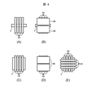
図4(A)~図4(E)は、それぞれ、図1に示すソーラースリット3の構成に関するバリエーションの一例を示す概念図である。なお、ソーラースリット3を通過する後方散乱X線は、線図が表された平面の手前から奥方向に向かって入射するものとする。以下の説明では、図4(A)~図4(E)に示す構成の各ソーラースリットを総称する場合に「3」という符号を付してソーラースリット3と称する。
4 (A) to 4 (E) are conceptual diagrams showing an example of variations relating to the configuration of the
図4(A)及び図4(B)は、検出器2が、各画素が1次元に少なくとも1行並んでいるライン状の検出器である場合を示し、図4(C)、図4(D)及び図4(E)は、それぞれ、検出器2が、各画素が2次元に並んでいるエリア状の検出器である場合を示す。なお、エリア状の検出器は、一定の面範囲に亘って後方散乱X線を検出可能である一方、ライン状の検出器は、それ自身がまたは被写体Tがそのラインに垂直な方向に移動されることによってそのラインを一辺として含む一定の面範囲に亘って後方散乱X線を検出可能となる。
4 (A) and 4 (B) show the case where the
図4(A)に示すソーラースリットでは、複数の遮蔽板3Aが一方向に互いに平行に配列しており、図示の左右方向に拡散する後方散乱X線は遮蔽されるが、図示の上下方向に拡散する後方散乱X線は通過する。しかしながら、検出器2がライン状の検出器であるため、この検出器2に一度に入射する後方散乱X線の線量は少ない。さらに図示の上下方向に拡散する散乱X線も遮蔽したい場合には、図4(B)に示すソーラースリットのように複数の遮蔽板3Aの手前及び奥側にそれぞれコリメータ3Bを設けることで遮蔽することが可能である。
In the solar slit shown in FIG. 4A, a plurality of shielding
図4(C)に示すソーラースリットでは、図4(A)に示すソーラースリットと同様に、複数の遮蔽板3Aが一方向に互いに平行に配列しており、図示の左右方向に拡散する後方散乱X線は遮蔽されるが、図示の上下方向に拡散する後方散乱X線は通過する。検出器2がエリア状の検出器であるため、図示の上下方向に拡散された後方散乱X線は検出器2に入射する。
In the solar slit shown in FIG. 4 (C), similarly to the solar slit shown in FIG. 4 (A), a plurality of shielding
この場合、図4(D)に示すソーラースリットのように遮蔽板3Aの手前及び奥側にそれぞれコリメータ3Bを設けると、検出器2がエリア状の検出器である利点を多少享受し難くなるものの、図示の上下方向の後方散乱X線を遮蔽することができる。
In this case, if the
また、図4(E)に示すソーラースリットのように互いに垂直な2方向に複数の遮蔽板3Aを並行に配列した格子状とすると、図示の左右方向及び上下方向に拡散する後方散乱X線を遮蔽することができる。
Further, when a plurality of shielding
本実施の形態では、ソーラースリット3の遮蔽板3Aのピッチと検出器2の画素ピッチで、得られる後方散乱X線画像の分解能が決まる。後方散乱X線の空間的な広がりがソーラースリット3で限定され、一方、後方散乱X線画像上の位置の区切りが検出器2によって限定される。
In the present embodiment, the resolution of the backscattered X-ray image obtained is determined by the pitch of the
従って、ソーラースリット3を構成する各遮蔽板3Aのピッチが検出器2の画素ピッチのn倍であると、分解能の低下を抑制することができる。ここで、nは整数(1,2,3,・・・)、または、整数を分母とする分数(1/2,1/3,1/4,・・・)である。
Therefore, when the pitch of each shielding
以上説明したように本実施の形態では、被写体Tと検出器2との間で合って検出器2の前にソーラースリット3を設置することにより、検出器2に入射する後方散乱X線の方向を限定し、後方散乱X線のボケを抑制することで、分解能を向上させている。
As described above, in the present embodiment, by installing the
また、上述のように本実施の形態では、X線源1の前に金属を材質とする第1のフィルタ4を設置して被写体Tに入射する照射X線のエネルギーを限定して特性X線が入射しないようにすることで、被写体Tを構成する元素に対して最もコントラストの高い後方散乱X線を生じさせることができる。
Further, as described above, in the present embodiment, the
また、上述のように本実施の形態では、検出器2の前に金属を材質とする第2のフィルタ5を設置して検出器2に入射する後方散乱X線のエネルギーを限定して蛍光X線が入射しないようにすることで、この検出器2に、最も高いコントラストが得られる後方散乱X線を検出させることができる。
Further, as described above, in the present embodiment, a
これらは、それぞれ、後方散乱X線がコンプトン散乱により発生していること、かつ、その発生量は照射X線のエネルギーと、被写体Tを構成する元素と、発生した後方散乱X線を検出する方向(散乱角度)と、に依存することに基づいている。 These are that the backscattered X-rays are generated by Compton scattering, and the amount of the generated amount is the energy of the irradiated X-rays, the elements constituting the subject T, and the direction for detecting the generated backscattered X-rays. It is based on (scattering angle) and dependence.
より具体的に説明すると、本実施の形態における被写体Tの一例としてエレベータのハンドレールに適用した場合には、このハンドレールを高速かつ高い精度で点検可能となるばかりでなく、点検結果に関する判定の自動化が可能となる。また、本実施の形態では、ハンドレールに対してX線源1と同じ側(X線源1の近傍側)に検出器2を設置することにより、X線源1と検出器2との配置調整が容易となるため、検出器2としてライン状の検出器を採用することができるようになり、空間分解能が向上すると共に、データの読み出しが高速化できる。また、上述した実施の形態によれば、ハンドレールをフレームから取り外して検査装置本体に挟み込ませる必要がなくなるため、検査の作業効率が向上するとともにメンテナンス作業時間を短縮することができる。また、上述のようにX線検査装置は、ハンドレールを挟み込む形態でなくなるため、全体として検査装置本体を小型化及び軽量化を図ることができるばかりでなく、このように検査装置本体が小型化、軽量化されることで操作性が向上して検査の作業効率をさらに高め、メンテナンスの作業時間を短縮することができる。
More specifically, when applied to an elevator handrail as an example of the subject T in the present embodiment, not only can this handrail be inspected at high speed and with high accuracy, but also the determination regarding the inspection result can be made. Automation is possible. Further, in the present embodiment, the
以上のように本実施の形態によれば、後方散乱X線を用いて高い分解能で定量的な測定を可能とするとともに、その測定結果に基づく判定を自動化することができるとともに、このような判定の自動化によって経時変化による被写体Tの劣化を予測することができる。 As described above, according to the present embodiment, it is possible to perform quantitative measurement with high resolution using backscattered X-rays, and it is possible to automate the determination based on the measurement result, and such determination. It is possible to predict the deterioration of the subject T due to the change with time by the automation of.
(2)第2の実施の形態
第2の実施の形態によるX線検査装置は、第1の実施の形態によるX線検査装置とほぼ同様の構成及び動作については説明を省略し、以下、両者の相違点を中心として説明する。
(2) Second Embodiment The X-ray inspection apparatus according to the second embodiment has almost the same configuration and operation as the X-ray inspection apparatus according to the first embodiment. The differences will be mainly explained.
図5は、第2の実施の形態によるX線検査装置の構成例を示す概念図である。第2の実施の形態では、被写体Tから戻った後方散乱X線の検出器としてスポット検出器2Aを使用する一方、X線源1から出力される照射X線XRを、前述の第1のフィルタ4を用いる代わりにピンホール7を用いて絞って被写体Tに照射する。
FIG. 5 is a conceptual diagram showing a configuration example of the X-ray inspection apparatus according to the second embodiment. In the second embodiment, the
スポット検出器2Aは、被写体Tで発生した後方散乱X線を検出する各画素が一点に集中的に配置するように構成されている。スポット検出器2Aは、被写体Tに向かう方向に垂直な2軸方向にX線源1とともに相対的に移動されて被写体Tを走査することにより、後方散乱X線XR1,XR2のうち部分的に散乱X線XR1のみを検出する機能を有する。
The
すなわち、被写体Tで散乱した後方散乱X線XR1,XR2のうち散乱X線XR2は、スポット検出器2Aに入射しないため、検出されない。一方、被写体Tで散乱した後方散乱X線XR1,XR2のうち散乱X線XR1のみがスポット検出器2Aに入射して検出される。
That is, of the backscattered X-rays XR1 and XR2 scattered by the subject T, the scattered X-rays XR2 are not detected because they do not enter the
本実施の形態によれば、第1の実施の形態とほぼ同様な効果を発揮するとともに、ピンホール7で一方向に絞った照射X線XRを、一方向のみに絞り込まれた後方散乱X線XR1としてスポット検出器2Aを用いて検出することで、第1の実施の形態のように被写体Tとスポット検出器2Aとの間であってスポット検出器2Aの前に前述のソーラースリット3を設置しなくても、高解像度の後方散乱X線XR1を計測することができる。
According to the present embodiment, the same effect as that of the first embodiment is exhibited, and the irradiation X-ray XR narrowed down in one direction by the
(3)第3の実施の形態
第3の実施の形態によるX線検査装置は、上述した各実施の形態によるX線検査装置とほぼ同様の構成及び動作については説明を省略し、以下、両者の相違点を中心として説明する。
(3) Third Embodiment The X-ray inspection apparatus according to the third embodiment has almost the same configuration and operation as the X-ray inspection apparatus according to each of the above-described embodiments. The differences will be mainly explained.
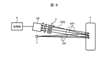
図6は、第3の実施の形態によるX線検査装置の構成例を示す概念図である。第3の実施の形態では、上述した各実施の形態とは異なり、後方散乱X線の検出器2Bとして、後方散乱X線を線状に検出するライン状の検出器、または、後方散乱X線を面状に検出するエリア状の検出器を使用する。
FIG. 6 is a conceptual diagram showing a configuration example of the X-ray inspection apparatus according to the third embodiment. In the third embodiment, unlike each of the above-described embodiments, the backscattered
X線源1は、上述した各実施の形態とは異なって第1のフィルタ4やピンホール7を通過させず、直接、発散光のX線XRを被写体Tに照射する。被写体Tで散乱した後方散乱X線のうち、後方散乱X線XR2は、ソーラースリット3で遮蔽されるため、検出器2Bに入射せず検出されない一方、散乱X線XR1のみが検出器2Bに入射して検出される。
Unlike each of the above-described embodiments, the X-ray source 1 does not pass through the
この際、被写体Tに入射するX線XRの進行方向に対してソーラースリット3の方向が例えば45度である場合、他の角度の後方散乱X線が入射し難いので、検出器2Bが出力するデータの定量化された測定値を得るためには望ましい。
At this time, when the direction of the
まず、検出器2Bがライン状の検出器である場合、図示の線図が表された平面及び被写体Tに向かう方向に垂直な平面における一方向に沿って各画素が配列している。被写体TがX線源1及び検出器2Bに対して相対的に上記垂直な平面に沿って移動することで、処理部9によって被写体Tに関する2次元の後方散乱X線画像が取得される。
First, when the
本実施の形態を被写体Tの一例としてエスカレータのハンドレールに適用する場合、例えば、これらX線源1及び検出器2Bの相対的な移動方向がハンドレールの長手方向になるように設置する。すなわち、通常エスカレータのハンドレールは自走させることができるため、ライン状の検出器である検出器2Bの各画素の配列方向がハンドレールの幅方向に平行になるように(上記自走方向に垂直になるように)した状態とすれば、処理部9は、自走するハンドレールの内部状態を表す後方散乱X線画像を自動的に取得することができる。
When the present embodiment is applied to the handrail of the escalator as an example of the subject T, for example, the X-ray source 1 and the
一方、検出器2Bがエリア状の検出器である場合、上記垂直な平面に沿って各画素が2次元に配列している。この場合、ハンドレールを移動しなくても、検出器2Bを用いてハンドレールについて計測し、処理部9がそのハンドレールについて2次元の後方散乱X線画像を取得することができる。
On the other hand, when the
このように本実施の形態をエスカレータのハンドレールの非破壊検査に適用した場合、ハンドレールの長手方向に検出器2Bを相対的に移動させると、ハンドレールの後方散乱X線画像を連続して取得することが可能となる。
When the present embodiment is applied to the non-destructive inspection of the handrail of the escalator in this way, when the
処理部9は、ハンドレール(被写体T)の同様な深さの内部に関して得られた後方散乱X線画像の各画素の測定値を加算平均することでS/N比を向上することができる。特にエスカレータのハンドレールは自走させることができるため、エリア状の検出器である検出器2Bを用いると、S/N比が高い後方散乱X線画像を取得することができる。
The
(4)第4の実施の形態
第4の実施の形態によるX線検査装置は、上述した各実施の形態によるX線検査装置とほぼ同様の構成及び動作については説明を省略し、以下、両者の相違点を中心として説明する。
(4) Fourth Embodiment The X-ray inspection apparatus according to the fourth embodiment has almost the same configuration and operation as the X-ray inspection apparatus according to each of the above-described embodiments. The differences will be mainly explained.
図7は、第4の実施の形態によるX線検査装置の構成例を示す概念図である。第4の実施の形態では、ソーラースリット3と検出器2AAとの組、及び、ソーラースリット3と検出器2ABとの組のように、複数の組を設置する形態とし、被写体Tに入射するX線XRの入射方向に対してソーラースリット3の方向が線対象になるように設置する。
FIG. 7 is a conceptual diagram showing a configuration example of the X-ray inspection apparatus according to the fourth embodiment. In the fourth embodiment, a plurality of sets are installed, such as a set of the
図示の例では、2個の検出器2AA,2ABを用いる場合を示している。2個の検出器2AA,2ABとして、それぞれ、第3の実施の形態において言及したライン状の検出器またはエリア状の検出器を採用する。 In the illustrated example, the case where two detectors 2AA and 2AB are used is shown. As the two detectors 2AA and 2AB, the line-shaped detector or the area-shaped detector mentioned in the third embodiment is adopted, respectively.
X線源1は、第3の実施の形態と同様に直接、発散光のX線XRを被写体Tに照射する。被写体Tで散乱した後方散乱X線のうち、ソーラースリット3を通過する散乱X線XR1のみが検出器2AA,2ABに入射して検出される。即ち、一方の散乱X線XR1が検出器2AAで検出される一方、他方の散乱X線XR1が検出器2ABで検出される。
The X-ray source 1 directly irradiates the subject T with the X-ray XR of the divergent light as in the third embodiment. Of the backscattered X-rays scattered by the subject T, only the scattered X-rays XR1 passing through the
このような構成とすると、第1の実施の形態とほぼ同様な効果を発揮するとともに、同時に検出される後方散乱X線の散乱量が2倍になるため、第3の実施の形態において前述のように加算平均することでS/N比を向上することができる。その際、被写体Tに入射するX線の方向に対するソーラースリット2のスリットの形成方向が平行に近いほど、後方散乱X線XR1の散乱方向が揃うため、検出器2AA,2ABがそれぞれ出力するデータに基づく定量値を得るためには望ましい。
With such a configuration, the effect is almost the same as that of the first embodiment, and the amount of backscattered X-rays detected at the same time is doubled. Therefore, the third embodiment is described above. The S / N ratio can be improved by adding and averaging as described above. At that time, the closer the formation direction of the slit of the
(5)第5の実施の形態
第5の実施の形態によるX線検査装置は、上述した各実施の形態によるX線検査装置とほぼ同様の構成及び動作については説明を省略し、以下、両者の相違点を中心として説明する。
(5) Fifth Embodiment The X-ray inspection apparatus according to the fifth embodiment has almost the same configuration and operation as the X-ray inspection apparatus according to each of the above-described embodiments. The differences will be mainly explained.
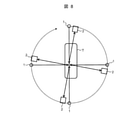
図8は、第5の実施の形態によるX線検査装置の構成例を示す概念図である。なお、図8では、構成の説明を簡素化するため、処理部9及びソーラースリット3の図示が省略されているが、実際には、上述した各実施の形態と同様に処理部9は検出器2などに接続されており、図示しないが、検出器2と被写体Tとの間における検出器2の前には、上述した各実施の形態と同様な構成のソーラースリット3が配置されている。なお、前述した各フィルタについても適宜図示を省略している。
FIG. 8 is a conceptual diagram showing a configuration example of the X-ray inspection apparatus according to the fifth embodiment. Although the
第5の実施の形態では、X線源1と不図示のソーラースリット3と検出器2との組が複数設置されており、被写体TへのX線の入射方向に関して、ソーラースリット3が被写体Tを中心として放射状に配置される。
In the fifth embodiment, a plurality of pairs of the X-ray source 1, the solar slit 3 (not shown), and the
本実施の形態では、被写体Tを固定しつつ、X線源1とソーラースリット3と検出器2との組を被写体Tを中心として回転させる。これにより、検出器2は、上述した放射状に配置される各位置から、X線源1から照射X線XRが入射される被写体Tを中心として多方向に発生する後方散乱X線を計測することができる。なお、X線源1と不図示のソーラースリット3と検出器2との組を固定し、被写体Tを回転させるようにしても良いことは云うまでもない。
In the present embodiment, while fixing the subject T, the pair of the X-ray source 1, the
不図示の処理部9は、検出器2によって出力されるデータを前述したように演算処理することにより、被写体Tに関する後方散乱X線画像を取得し、これに基づいて上記各実施の形態と同様に判定を実施することができる。
The processing unit 9 (not shown) acquires a backscattered X-ray image of the subject T by performing arithmetic processing on the data output by the
本実施の形態によれば、前述した各実施の形態と同様の効果を発揮することができるとともに、被写体Tについてより他方向からより詳細な内部構造に関する検査を実施することができる。 According to the present embodiment, the same effects as those of the above-described embodiments can be exhibited, and the subject T can be inspected for a more detailed internal structure from another direction.
(6)第6の実施の形態
第6の実施の形態によるX線検査装置は、上述した各実施の形態によるX線検査装置とほぼ同様の構成及び動作については説明を省略し、以下、両者の相違点を中心として説明する。
(6) Sixth Embodiment The X-ray inspection apparatus according to the sixth embodiment has almost the same configuration and operation as the X-ray inspection apparatus according to each of the above-described embodiments. The differences will be mainly explained.
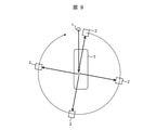
図9は、第6の実施の形態によるX線検査装置の構成例を示す概念図である。なお、図9では、構成の説明を簡素化するため、処理部9及びソーラースリット3の図示が省略されているが、実際には、上述した第5の実施の形態と同様に処理部9は検出器2などに接続されており、図示しないが、検出器2と被写体Tとの間における検出器2の前には、上述した各実施の形態と同様な構成のソーラースリット3が配置されている。なお、前述した各フィルタについても適宜図示を省略している。
FIG. 9 is a conceptual diagram showing a configuration example of the X-ray inspection apparatus according to the sixth embodiment. Although the
第6の実施の形態では、不図示のソーラースリット3と検出器2との組を組とし、X線源1と被写体Tとの相対的な配置関係を固定した状態で、被写体Tを中心としてこれら不図示のソーラースリット3と検出器2との組を回転させる。これにより、検出器2は、上述した放射状に配置される各位置から、X線源1から照射X線XRが入射される被写体Tを中心として多方向に発生する後方散乱X線を計測することができる。
In the sixth embodiment, a pair of a
不図示の処理部9は、検出器2によって出力されるデータを前述したように演算処理することにより、被写体Tに関する後方散乱X線画像を取得し、これに基づいて上記各実施の形態と同様に判定を実施することができる。また、様々な方向から得られた後方散乱X線画像を3次元再構成演算処理することにより、被写体Tの断面像を得ることができる。
The processing unit 9 (not shown) acquires a backscattered X-ray image of the subject T by performing arithmetic processing on the data output by the
本実施の形態によれば、前述した各実施の形態と同様の効果を発揮することができるとともに、被写体Tについてより他方向からより詳細な内部構造に関する検査を実施することができる。 According to the present embodiment, the same effects as those of the above-described embodiments can be exhibited, and the subject T can be inspected for a more detailed internal structure from another direction.
(7)その他の実施形態
上記実施形態は、本発明を説明するための例示であり、本発明をこれらの実施形態にのみ限定する趣旨ではない。本発明は、その趣旨を逸脱しない限り、様々な形態で実施することができる。例えば、上記実施形態では、エスカレータのハンドレールを例として説明したが、これに限定されるものではない。被写体Tの表面に検査装置を添わせることで検査が可能であることから、上述したエスカレータのハンドレールの他にも、配管の亀裂若しくはジョイント部のずれ、または、壁若しくは床面の探傷へ適用することができる。
(7) Other Embodiments The above embodiments are examples for explaining the present invention, and the present invention is not intended to be limited only to these embodiments. The present invention can be carried out in various forms as long as it does not deviate from the gist thereof. For example, in the above embodiment, the handrail of the escalator has been described as an example, but the present invention is not limited thereto. Since inspection can be performed by attaching an inspection device to the surface of the subject T, it can be applied to cracks in pipes, misalignment of joints, or flaw detection on walls or floors, in addition to the above-mentioned escalator handrails. can do.
本発明は、後方散乱X線を用いて内部構造を破壊することなく検査を実施する非破壊検査装置及び非破壊検査方法に広く適用することができる。 The present invention can be widely applied to non-destructive inspection devices and non-destructive inspection methods that use backscatter X-rays to perform inspections without destroying the internal structure.
2、2A,2B,2AA,2AB……検出器、3……ソーラースリット、4……第1のフィルタ、5……第2のフィルタ、9……処理部。 2, 2A, 2B, 2AA, 2AB ... detector, 3 ... solar slit, 4 ... first filter, 5 ... second filter, 9 ... processing unit.
Claims (14)
被写体の位置を基準として前記X線源の近傍側に設置されており前記X線源から照射されたX線が前記被写体で散乱した後方散乱X線を検出する検出器と、
前記検出器と前記被写体との間における前記検出器の前に設置されたソーラースリットと、
前記X線源と前記被写体との間における前記X線源の前に設置された第1のフィルタと、
前記検出器と前記被写体との間における前記検出器の前に設置された第2のフィルタと、
前記検出器による検出結果をクラスタリングした実行結果に基づく後方散乱X線で表される前記被写体の内部の断面構造を表す後方散乱X線画像を所定基準と比較することで正常及び異常の判定を実施する処理部と、
を備えることを特徴とする非破壊検査装置。 An X-ray source that irradiates X-rays and
A detector installed near the X-ray source with respect to the position of the subject and detecting backscattered X-rays in which X-rays emitted from the X-ray source are scattered by the subject.
A solar slit installed in front of the detector between the detector and the subject,
A first filter installed in front of the X-ray source between the X-ray source and the subject,
A second filter installed in front of the detector between the detector and the subject,
Normal and abnormal judgments are made by comparing the backscattered X-ray image showing the internal cross-sectional structure of the subject represented by the backscattered X-rays based on the execution result of clustering the detection results by the detector with a predetermined reference. Processing unit and
A non-destructive inspection device characterized by being equipped with.
前記X線源のターゲットから発生する前記照射X線のエネルギーを特性X線が入射しない第1の帯域に限定して該第1の帯域外のエネルギーの特性X線をフィルタリングする金属を材質とすることを特徴とする請求項1に記載の非破壊検査装置。 The first filter is
The material is a metal that limits the energy of the irradiated X-rays generated from the target of the X-ray source to the first band in which the characteristic X-rays are not incident and filters the characteristic X-rays of the energy outside the first band. The non-destructive inspection device according to claim 1, wherein the non-destructive inspection device is characterized by the above.
前記X線源のターゲットの材質を構成する元素の一つ下の原子番号の元素を材質とすることを特徴とする請求項1に記載の非破壊検査装置。 The first filter is
The nondestructive inspection apparatus according to claim 1, wherein the material is an element having an atomic number one below the element constituting the material of the target of the X -ray source.
前記被写体から発生し前記検出器に入射するX線のエネルギーを蛍光X線が入射しない第2の帯域に限定して該第2の帯域外のエネルギーの蛍光X線をフィルタリングする金属を材質とすることを特徴とする請求項1に記載の非破壊検査装置。 The second filter is
The material is a metal that limits the energy of the X-rays generated from the subject and incident on the detector to the second band in which the fluorescent X-rays are not incident , and filters the fluorescent X-rays of the energy outside the second band. The non-destructive inspection apparatus according to claim 1, wherein the non-destructive inspection apparatus is characterized.
前記被写体の材質を構成する元素の一つ下の原子番号の元素を材質とすることを特徴とする請求項1に記載の非破壊検査装置。 The second filter is
The non-destructive inspection apparatus according to claim 1, wherein the material is an element having an atomic number one below the element constituting the material of the subject.
複数のスリット板が一方向に並列に配列する構造であることを特徴とする請求項1に記載の非破壊検査装置。 The solar slit is
The nondestructive inspection apparatus according to claim 1, wherein a plurality of slit plates are arranged in parallel in one direction.
複数のスリット板が互いに垂直な2方向に並列に配列する格子状の構造であることを特徴とする請求項1に記載の非破壊検査装置。 The solar slit is
The nondestructive inspection apparatus according to claim 1, wherein a plurality of slit plates have a lattice-like structure in which a plurality of slit plates are arranged in parallel in two directions perpendicular to each other.
被写体の位置を基準として前記X線源の近傍側に検出器を配置する検出器配置ステップ
と、
前記検出器と前記被写体との間における前記検出器の前にソーラースリットを設置するーラースリット配置ステップと、
前記X線源と前記被写体との間における前記X線源の前に第1のフィルタを設置する第1のフィルタ配置ステップと、
前記検出器と前記被写体との間における前記検出器の前に第2のフィルタを設置する第2のフィルタ配置ステップと、
前記検出器を用いて、前記X線源から照射されたX線が前記被写体で散乱した後方散乱X線を検出する検出ステップと、
処理部が、前記検出器による検出結果をクラスタリングした実行結果に基づく後方散乱X線で表される前記被写体の内部の断面構造を表す後方散乱X線画像を所定基準と比較することで正常及び異常の判定を実施する処理ステップと、
を有することを特徴とする非破壊検査方法。 The irradiation step in which the X-ray source irradiates X-rays,
A detector placement step for arranging a detector near the X-ray source with respect to the position of the subject, and a detector placement step.
A solar slit placement step for installing a solar slit in front of the detector between the detector and the subject,
A first filter placement step in which a first filter is placed in front of the X-ray source between the X-ray source and the subject.
A second filter placement step in which a second filter is placed in front of the detector between the detector and the subject.
A detection step of detecting backscattered X-rays scattered by the subject by X-rays emitted from the X-ray source using the detector.
The processing unit compares the backscattered X-ray image showing the internal cross-sectional structure of the subject represented by the backscattered X-rays based on the execution result of clustering the detection results by the detector with a predetermined reference, and is normal and abnormal. And the processing step to carry out the judgment of
A non-destructive inspection method characterized by having.
Priority Applications (1)
| Application Number | Priority Date | Filing Date | Title |
|---|---|---|---|
| JP2018009071A JP7009230B2 (en) | 2018-01-23 | 2018-01-23 | Non-destructive inspection equipment and non-destructive inspection method |
Applications Claiming Priority (1)
| Application Number | Priority Date | Filing Date | Title |
|---|---|---|---|
| JP2018009071A JP7009230B2 (en) | 2018-01-23 | 2018-01-23 | Non-destructive inspection equipment and non-destructive inspection method |
Publications (2)
| Publication Number | Publication Date |
|---|---|
| JP2019128204A JP2019128204A (en) | 2019-08-01 |
| JP7009230B2 true JP7009230B2 (en) | 2022-01-25 |
Family
ID=67473098
Family Applications (1)
| Application Number | Title | Priority Date | Filing Date |
|---|---|---|---|
| JP2018009071A Active JP7009230B2 (en) | 2018-01-23 | 2018-01-23 | Non-destructive inspection equipment and non-destructive inspection method |
Country Status (1)
| Country | Link |
|---|---|
| JP (1) | JP7009230B2 (en) |
Citations (10)
| Publication number | Priority date | Publication date | Assignee | Title |
|---|---|---|---|---|
| JP2000055839A (en) | 1998-08-05 | 2000-02-25 | Nippon Steel Corp | Fluorescent x-ray analysis device |
| JP2001091699A (en) | 1999-07-23 | 2001-04-06 | Koninkl Philips Electronics Nv | Radiation analyzing device with variable collimator |
| JP2001208705A (en) | 2000-01-27 | 2001-08-03 | Mitsubishi Heavy Ind Ltd | Scattered x-ray type defect detector, and x-ray detector |
| JP2007010559A (en) | 2005-07-01 | 2007-01-18 | Axion Japan:Kk | Collimator for radiation, radiation detection device and manufacturing method for collimator for radiation |
| JP2008203245A (en) | 2007-01-23 | 2008-09-04 | Sii Nanotechnology Inc | X-ray analysis apparatus and x-ray analysis method |
| JP2012013423A (en) | 2010-06-29 | 2012-01-19 | Nippon Steel Corp | X-ray stress measuring apparatus |
| JP2013253969A (en) | 2012-05-22 | 2013-12-19 | Aribex Inc | Handheld x-ray system for 3d scatter imaging |
| JP2017009356A (en) | 2015-06-18 | 2017-01-12 | 新東工業株式会社 | Residual stress measurement instrument and residual stress measurement method |
| JP2017510827A (en) | 2013-12-22 | 2017-04-13 | アプライド マテリアルズ インコーポレイテッドApplied Materials,Incorporated | Deposition monitoring system and operation method thereof |
| JP2017142261A (en) | 2017-04-13 | 2017-08-17 | 国立研究開発法人物質・材料研究機構 | X-ray imaging apparatus and method of using the same |
Family Cites Families (2)
| Publication number | Priority date | Publication date | Assignee | Title |
|---|---|---|---|---|
| JPS5832200A (en) * | 1981-08-20 | 1983-02-25 | ワコー電子株式会社 | Intensifying method for monochromatism of characteristic x rays |
| NL2009049C2 (en) * | 2012-06-21 | 2013-12-24 | Entech Scient B V | Method and device for identifying unknown substances in an object. |
-
2018
- 2018-01-23 JP JP2018009071A patent/JP7009230B2/en active Active
Patent Citations (10)
| Publication number | Priority date | Publication date | Assignee | Title |
|---|---|---|---|---|
| JP2000055839A (en) | 1998-08-05 | 2000-02-25 | Nippon Steel Corp | Fluorescent x-ray analysis device |
| JP2001091699A (en) | 1999-07-23 | 2001-04-06 | Koninkl Philips Electronics Nv | Radiation analyzing device with variable collimator |
| JP2001208705A (en) | 2000-01-27 | 2001-08-03 | Mitsubishi Heavy Ind Ltd | Scattered x-ray type defect detector, and x-ray detector |
| JP2007010559A (en) | 2005-07-01 | 2007-01-18 | Axion Japan:Kk | Collimator for radiation, radiation detection device and manufacturing method for collimator for radiation |
| JP2008203245A (en) | 2007-01-23 | 2008-09-04 | Sii Nanotechnology Inc | X-ray analysis apparatus and x-ray analysis method |
| JP2012013423A (en) | 2010-06-29 | 2012-01-19 | Nippon Steel Corp | X-ray stress measuring apparatus |
| JP2013253969A (en) | 2012-05-22 | 2013-12-19 | Aribex Inc | Handheld x-ray system for 3d scatter imaging |
| JP2017510827A (en) | 2013-12-22 | 2017-04-13 | アプライド マテリアルズ インコーポレイテッドApplied Materials,Incorporated | Deposition monitoring system and operation method thereof |
| JP2017009356A (en) | 2015-06-18 | 2017-01-12 | 新東工業株式会社 | Residual stress measurement instrument and residual stress measurement method |
| JP2017142261A (en) | 2017-04-13 | 2017-08-17 | 国立研究開発法人物質・材料研究機構 | X-ray imaging apparatus and method of using the same |
Also Published As
| Publication number | Publication date |
|---|---|
| JP2019128204A (en) | 2019-08-01 |
Similar Documents
| Publication | Publication Date | Title |
|---|---|---|
| US7885381B2 (en) | Method for inspecting pipes, and radiographic non-destructive inspection apparatus | |
| Kolkoori et al. | A new X-ray backscatter imaging technique for non-destructive testing of aerospace materials | |
| JP2009525084A (en) | Projection image and tomography image creation method using X-ray system | |
| JP2000321221A (en) | Method and system for producing projection data by ct system | |
| JP2008298762A (en) | Laminography inspection system and its method | |
| US20150377804A1 (en) | Collection of tomographic inspection data using compton scattering | |
| JP2008275352A (en) | Inspection method and device of pipe | |
| EP2679989A2 (en) | X-ray CT system for measuring three dimensional shapes and measuring method of three dimensional shapes by X-ray CT system | |
| JP7009230B2 (en) | Non-destructive inspection equipment and non-destructive inspection method | |
| EP2711695B1 (en) | Method of getting a tomogram used by X-ray computed tomography and X-ray computed tomography system based on its method | |
| US20190025231A1 (en) | A method of detection of defects in materials with internal directional structure and a device for performance of the method | |
| CN112649451B (en) | Fast industrial computed tomography for large objects | |
| JP5610885B2 (en) | X-ray imaging apparatus and imaging method | |
| US8858076B2 (en) | Multi-step contrast sensitivity gauge | |
| Ghandourah et al. | Evaluation of Welding Imperfections with X-ray Computed Laminography for NDT Inspection of Carbon Steel Plates | |
| WO2018092256A1 (en) | Inline x-ray inspection system and imaging method for inline x-ray inspection system | |
| JP5030056B2 (en) | Nondestructive inspection method and apparatus | |
| Ewert et al. | X-ray tomographic in-service inspection of girth welds-The European project TomoWELD | |
| JP6598205B2 (en) | Nondestructive inspection method and apparatus | |
| JP4062232B2 (en) | X-ray CT apparatus and imaging method using X-ray CT apparatus | |
| JP2012083277A (en) | X-ray detector, x-ray ct apparatus using the same, and method for capturing x-ray ct | |
| JP5492634B2 (en) | Radiation tomography method and radiation tomography apparatus | |
| Ghandourah et al. | Evaluation of Welding Defects with X-ray Digital Laminography for NDT inspection of Carbon Steel Plate | |
| JP2024005926A (en) | X-ray inspection device, escalator inspection device and method | |
| KR101127568B1 (en) | Outer surface contact type gamma tomography apparatus for industrial process diagnosis and its method |
Legal Events
| Date | Code | Title | Description |
|---|---|---|---|
| A621 | Written request for application examination |
Free format text: JAPANESE INTERMEDIATE CODE: A621 Effective date: 20200701 |
|
| A977 | Report on retrieval |
Free format text: JAPANESE INTERMEDIATE CODE: A971007 Effective date: 20210419 |
|
| A131 | Notification of reasons for refusal |
Free format text: JAPANESE INTERMEDIATE CODE: A131 Effective date: 20210601 |
|
| A521 | Written amendment |
Free format text: JAPANESE INTERMEDIATE CODE: A523 Effective date: 20210727 |
|
| TRDD | Decision of grant or rejection written | ||
| A01 | Written decision to grant a patent or to grant a registration (utility model) |
Free format text: JAPANESE INTERMEDIATE CODE: A01 Effective date: 20211228 |
|
| A61 | First payment of annual fees (during grant procedure) |
Free format text: JAPANESE INTERMEDIATE CODE: A61 Effective date: 20220112 |
|
| R150 | Certificate of patent or registration of utility model |
Ref document number: 7009230 Country of ref document: JP Free format text: JAPANESE INTERMEDIATE CODE: R150 |