JP7009099B2 - Drip-proof structure of the housing - Google Patents
Drip-proof structure of the housing Download PDFInfo
- Publication number
- JP7009099B2 JP7009099B2 JP2017140758A JP2017140758A JP7009099B2 JP 7009099 B2 JP7009099 B2 JP 7009099B2 JP 2017140758 A JP2017140758 A JP 2017140758A JP 2017140758 A JP2017140758 A JP 2017140758A JP 7009099 B2 JP7009099 B2 JP 7009099B2
- Authority
- JP
- Japan
- Prior art keywords
- housing
- wiring
- hole
- tubular member
- drip
- Prior art date
- Legal status (The legal status is an assumption and is not a legal conclusion. Google has not performed a legal analysis and makes no representation as to the accuracy of the status listed.)
- Active
Links
Images


Landscapes
- Insertion, Bundling And Securing Of Wires For Electric Apparatuses (AREA)
- Casings For Electric Apparatus (AREA)
- Studio Devices (AREA)
Description
本発明は、内部に電気配線の一部を収容する筐体の該内部に液体が浸入するのを防止するとともに、電気配線が筐体内部から筐体外部に露出する部分において該電気配線を貫通保持するための、筐体の防滴構造に関する技術分野に属する。 The present invention prevents liquid from entering the inside of the housing that houses a part of the electrical wiring inside, and penetrates the electrical wiring in the portion where the electrical wiring is exposed from the inside of the housing to the outside of the housing. It belongs to the technical field related to the drip-proof structure of the housing for holding.
従来より、筐体内部に液体が浸入するのを防止するとともに、細長い部材を貫通保持するための、防滴構造が考えられている。
Conventionally, a drip-proof structure has been considered for preventing liquid from entering the inside of a housing and for penetrating and holding an elongated member.
たとえば、特許文献1には、自動車の燃料タンクの構造であって、燃料タンク内に設けられるセンサのリード線と該センサと電気的に接続されるハーネスとを接続するための金属端子を貫通保持する樹脂製フランジの端子支持部(配線保持部)を備え、金属端子と該端子支持部との間に、ウレタン系の接着剤からなるシール膜を設ける構造が開示されている。 For example, Patent Document 1 describes a structure of a fuel tank of an automobile, in which a metal terminal for connecting a lead wire of a sensor provided in the fuel tank and a harness electrically connected to the sensor is penetrated and held. A structure is disclosed in which a terminal support portion (wiring holding portion) of a resin flange is provided, and a sealing film made of a urethane-based adhesive is provided between the metal terminal and the terminal support portion.
この特許文献1の構造によって、金属端子と端子支持部との間から燃料が漏れ出ることを防止することができるとともに、燃料タンク内部に燃料以外の液体が浸入するのを防止することができる。 According to the structure of Patent Document 1, it is possible to prevent fuel from leaking from between the metal terminal and the terminal support portion, and it is possible to prevent liquids other than fuel from entering the inside of the fuel tank.
ところで、内部に電気配線の一部が収容された筐体から、該電気配線の残部を筐体外部に露出させるときにも、電気配線が通過する部分に、筐体内部に液体が浸入するのを防止する防滴構造が適用される。このような電気配線が通過する部分に設けられる防滴構造においては、配線保持部が電気配線を保持することになる。 By the way, even when the remaining part of the electric wiring is exposed to the outside of the housing from the housing in which a part of the electric wiring is housed inside, the liquid infiltrates into the portion through which the electric wiring passes. A drip-proof structure is applied to prevent. In the drip-proof structure provided in the portion through which the electric wiring passes, the wiring holding portion holds the electric wiring.
配線保持部が電気配線を保持するような構成では、特許文献1に記載のような構造を適用することは困難である。すなわち、特許文献1のように、電気配線と配線保持部との間に接着剤からなるシール膜が設けられる構成では、電気配線が配線保持部に強固に固定された後、配線保持部が筐体に組み付けられる。このとき、電気配線における、回路基板への接続部から配線保持部までの長さが長くなりすぎることがあり、配線保持部を筐体に組み付けた際に、筐体内部で電気配線が撓んで、電気配線と該電気配線の接続部品(回路基板など)との接続部分に負荷がかかって、最悪の場合、電気配線と上記接続部品との接続が切れてしまうおそれがある。また、電気配線を筐体内部に収容しきれずに、配線保持部の筐体への組み付け自体が困難になるおそれもある。 In a configuration in which the wiring holding portion holds the electrical wiring, it is difficult to apply the structure as described in Patent Document 1. That is, in a configuration in which a sealing film made of an adhesive is provided between the electrical wiring and the wiring holding portion as in Patent Document 1, the wiring holding portion is molded after the electrical wiring is firmly fixed to the wiring holding portion. It is attached to the body. At this time, the length from the connection portion to the circuit board to the wiring holding portion in the electrical wiring may become too long, and when the wiring holding portion is assembled to the housing, the electrical wiring bends inside the housing. , A load is applied to the connection portion between the electrical wiring and the connection component (circuit board, etc.) of the electrical wiring, and in the worst case, the connection between the electrical wiring and the connection component may be cut off. In addition, the electrical wiring cannot be completely accommodated inside the housing, which may make it difficult to assemble the wiring holding portion to the housing.
これを防止するために、電気配線のおける、回路基板への接続部から配線保持部までの部分の適切な長さを予め算出して、電気配線を配線保持部に固定することが考えられる。しかし、電気配線が複数本あるような場合には、各電気配線に対して調整する必要があるとともに、配線も複雑になるため、各電気配線の筐体内部における長さを予め算出することが困難となる。また、回路基板への接続のやり直しなど、電気配線の上記部分の長さを短くせざるを得ない作業を行うことができなくなってしまう。 In order to prevent this, it is conceivable to calculate in advance an appropriate length of the portion of the electrical wiring from the connection portion to the circuit board to the wiring holding portion and fix the electrical wiring to the wiring holding portion. However, when there are multiple electrical wirings, it is necessary to make adjustments for each electrical wiring and the wiring becomes complicated, so it is necessary to calculate the length of each electrical wiring inside the housing in advance. It will be difficult. In addition, it becomes impossible to perform work that has to shorten the length of the above-mentioned part of the electric wiring, such as reconnection to the circuit board.
本発明は、斯かる点に鑑みてなされたものであり、その目的とするところは、高い防滴性を確保しつつ、配線保持部の筐体へ組み付けを容易にするとともに、配線保持部を筐体へ組み付ける際の電気配線への負荷の発生を抑制することにある。 The present invention has been made in view of these points, and an object of the present invention is to facilitate assembly of the wiring holding portion to the housing while ensuring high drip-proof property, and to provide the wiring holding portion. The purpose is to suppress the generation of a load on the electrical wiring when assembling to the housing.
上記課題を解決するために、本発明は、内部に電気配線の一部を収容する筐体の該内部に液体が浸入するのを防止するとともに、上記電気配線が上記筐体内部から筐体外部に露出する部分において上記電気配線を貫通保持するための、筐体の防滴構造を対象として、上記電気配線は複数あり、上記筐体に形成された孔部に嵌合される、弾性変形可能な筒状の筒状部材と、上記筒状部材の筒内に該筒状部材と一体形成され、上記各電気配線を上記筒状部材の筒軸方向に通過させてそれぞれ貫通保持するための複数の貫通孔を有し、弾性変形可能な1つの柱状又は板状の部材で構成された配線保持部と、を備え、上記筒状部材は、上記筒軸方向から見た形状が、上記孔部よりも大きい形状をなすとともに、上記筐体の上記孔部に嵌合されたときに、上記配線保持部を上記筒軸方向に対して直交する方向に圧縮して、上記各貫通孔をそれぞれ縮径させるように構成されており、上記縮径後の上記各貫通孔の直径は、それぞれ、上記貫通孔が縮径する前の、当該貫通孔に挿通された上記電気配線の直径以下である、というものにした。 In order to solve the above problems, the present invention prevents liquid from entering the inside of the housing that houses a part of the electric wiring inside, and the electric wiring is from the inside of the housing to the outside of the housing. There are a plurality of the electric wirings for the drip-proof structure of the housing for penetrating and holding the electric wirings in the exposed portion, and the electric wirings can be elastically deformed by being fitted into the holes formed in the housings. A plurality of tubular members, which are integrally formed with the tubular member in the cylinder of the tubular member, and each of the electric wirings is passed through the tubular member in the tubular axial direction and held through the tubular member. The tubular member is provided with a wiring holding portion having a through hole and made of one columnar or plate-shaped member that can be elastically deformed. It has a larger shape, and when it is fitted into the hole portion of the housing, the wiring holding portion is compressed in a direction orthogonal to the cylinder axis direction, and each through hole is shrunk. The diameter of each through hole after the diameter reduction is smaller than or equal to the diameter of the electrical wiring inserted through the through hole before the through hole is reduced in diameter. I made it.
この構成によると、筒状部材が筐体の孔部に嵌合する前の状態、つまり、配線保持部が筒状部材を介して筐体に組み付けられる前の状態では、配線保持部の貫通孔は縮径されておらず、配線保持部に電気配線が強固に固定されていないため、配線保持部と電気配線との相対位置を自由に調整することができる。そのため、配線保持部を筐体に組み付けるときには、電気配線における、回路基板への接続部から配線保持部まで部分、つまり、電気配線における筐体内部に収容される部分に撓みが生じないように、配線保持部と電気配線との相対位置を調整した後に、配線保持部を筐体に組み付けるようにすることもできる。これにより、配線保持部の筐体への組み付けを容易にするとともに、配線保持部を筐体に組み付ける際の電気配線への負荷の発生を抑えることができる。 According to this configuration, in the state before the tubular member is fitted into the hole portion of the housing, that is, in the state before the wiring holding portion is assembled to the housing via the tubular member, the through hole of the wiring holding portion is provided. Since the diameter of the wire is not reduced and the electrical wiring is not firmly fixed to the wiring holding portion, the relative position between the wiring holding portion and the electrical wiring can be freely adjusted. Therefore, when assembling the wiring holding portion to the housing, the portion of the electrical wiring from the connection portion to the circuit board to the wiring holding portion, that is, the portion accommodated inside the housing in the electrical wiring is not bent. It is also possible to assemble the wiring holding portion to the housing after adjusting the relative position between the wiring holding portion and the electrical wiring. This facilitates the assembly of the wiring holding portion to the housing and suppresses the generation of a load on the electrical wiring when the wiring holding portion is assembled to the housing.
また、筒状部材を筐体の孔部に嵌合させた際には、配線保持部の貫通孔は、その直径が、該貫通孔が縮径する前の電気配線の直径以下となるように縮径するため、貫通孔の内周縁部と電気配線とが密着状態となり、電気配線における貫通孔内に位置する部分と配線保持部との間には、隙間が形成されない。これにより、筒状部材を筐体の孔部に嵌合させた後には、筐体内部に液体が浸入することが防止されるため、高い防滴性を確保することができる。 Further, when the tubular member is fitted into the hole portion of the housing, the diameter of the through hole of the wiring holding portion is equal to or less than the diameter of the electric wiring before the through hole is reduced in diameter. Since the diameter is reduced, the inner peripheral edge portion of the through hole and the electrical wiring are in close contact with each other, and no gap is formed between the portion located in the through hole in the electrical wiring and the wiring holding portion. As a result, after the tubular member is fitted into the hole of the housing, the liquid is prevented from entering the inside of the housing, so that high drip-proof property can be ensured.
したがって、高い防滴性を確保しつつ、配線保持部の筐体へ組み付けを容易にするとともに、配線保持部を筐体へ組み付ける際の電気配線への負荷の発生を抑制することができる。 Therefore, while ensuring high drip-proof property, it is possible to facilitate assembly of the wiring holding portion to the housing and suppress the generation of a load on the electrical wiring when the wiring holding portion is assembled to the housing .
また、電気配線が複数ある場合には、電気配線における筐体内部に収容される部分の適切な長さを予め算出することが困難であるため、筐体に配線保持部を組み付ける前に、配線保持部と電気配線との相対位置を自由に調整することで、配線保持部を筐体へ組み付ける際の電気配線への負荷の発生を抑制するという効果を適切に発揮することができる。 Further, when there are a plurality of electrical wirings, it is difficult to calculate in advance an appropriate length of the portion of the electrical wiring accommodated inside the housing. Therefore, wiring is performed before assembling the wiring holding portion to the housing. By freely adjusting the relative positions of the holding portion and the electrical wiring, the effect of suppressing the generation of a load on the electrical wiring when the wiring holding portion is assembled to the housing can be appropriately exhibited.
また、電気配線が複数ある場合には、各電気配線の撓みを防止することに加えて、電気配線同士の絡まりも防止する必要がある。これに対して、本発明の防滴構造を適用すれば、電気配線が複数あったとしても、配線保持部を筐体に組み付ける前に、各電気配線と配線保持部との相対位置を調整して、各電気配線における筐体内部に収容される部分の適切な長さをそれぞれ調整することができるため、各電気配線の撓み及び電気配線同士の絡まりを防止することができる。 Further, when there are a plurality of electric wirings, it is necessary to prevent the electric wirings from being entangled with each other in addition to preventing the electric wirings from bending. On the other hand, if the drip-proof structure of the present invention is applied, even if there are a plurality of electrical wirings, the relative positions of each electrical wiring and the wiring holding portion can be adjusted before assembling the wiring holding portion to the housing. Therefore, since the appropriate length of the portion of each electric wiring housed inside the housing can be adjusted, it is possible to prevent the electric wiring from bending and getting entangled with each other.
また、各電気配線に対応した各貫通孔は、筒状部材を筐体の孔部に嵌合させた際にそれぞれ縮径するため、高い防滴性を確保することもできる。 Further, since each through hole corresponding to each electric wiring has a reduced diameter when the tubular member is fitted into the hole portion of the housing, high drip-proof property can be ensured.
上記筐体の防滴構造において、上記筒状部材は、上記筒軸方向から見た形状が、上記孔部よりも大きい該孔部の相似形をなしている、ことが望ましい。 In the drip-proof structure of the housing, it is desirable that the tubular member has a shape similar to that of the hole portion, which is larger than the hole portion when viewed from the cylinder axis direction.
このことにより、筒状部材が孔部に嵌合したときには、筒状部材は筒内側に均一に縮小する。これにより、配線保持部が均一に圧縮され、貫通孔も均一に縮径するため、電気配線における貫通孔内に位置する部分と配線保持部との間には、一層隙間が形成されにくくなる。この結果、筐体の防滴性をより向上させることができる。 As a result, when the tubular member fits into the hole, the tubular member uniformly shrinks inside the cylinder. As a result, the wiring holding portion is uniformly compressed and the through hole is also uniformly reduced in diameter, so that it becomes more difficult to form a gap between the portion located in the through hole in the electrical wiring and the wiring holding portion. As a result, the drip-proof property of the housing can be further improved.
上記筐体の防滴構造において、上記配線保持部は、上記筒状部材と協働して、上記筒軸方向の筐体内部側に凹部が形成されるように、上記筒状部材内に位置している、ことが望ましい。 In the drip-proof structure of the housing, the wiring holding portion is positioned in the tubular member so as to form a recess on the inner side of the housing in the cylindrical axis direction in cooperation with the tubular member. It is desirable to do.
この構成によると、筒状部材における凹部を構成する部分は、筐体の孔部を通って該筐体内部に挿入しやすいように変形させることができる。そして、筒状部材における凹部を構成する部分を筐体内部に挿入すれば、筒状部材の残りの部分を、上記孔部の周縁に沿わせながら容易に筐体内部に挿入することができる。これにより、配線保持部の組み付けを一層容易にすることができる。 According to this configuration, the portion of the tubular member that constitutes the recess can be deformed so that it can be easily inserted into the housing through the hole in the housing. Then, if the portion of the tubular member that constitutes the recess is inserted into the housing, the remaining portion of the tubular member can be easily inserted into the housing along the peripheral edge of the hole. This makes it possible to further facilitate the assembly of the wiring holding portion.
上記配線保持部と上記筒状部材とで、上記筐体内部側に凹部が形成された、筐体の防滴構造において、上記凹部内には接着剤が充填されている、ことが望ましい。 In the drip-proof structure of the housing in which a recess is formed on the inner side of the housing between the wiring holding portion and the tubular member, it is desirable that the recess is filled with an adhesive.
この構成により、防滴性を一層向上させることができる。 With this configuration, the drip-proof property can be further improved.
上記筐体の防滴構造において、上記筐体が、飛行体に取り付けられるカメラの筐体であるときには。上記筐体は、上記孔部が下側に位置するように上記飛行体に取り付けられている、ことが望ましい。 In the drip-proof structure of the housing, when the housing is a housing of a camera attached to a flying object. It is desirable that the housing is attached to the flying object so that the hole is located on the lower side.
すなわち、孔部が下側に位置していれば、例えば、雨天の中で飛行体を動作させたとしても、筐体内部に雨水が浸入しにくいようにすることができる。これにより、上記筐体が飛行体に取り付けられるカメラの筐体である場合であっても、防滴性を適切に確保することができる。 That is, if the hole is located on the lower side, it is possible to prevent rainwater from entering the inside of the housing even if the flying object is operated in rainy weather, for example. Thereby, even when the housing is the housing of the camera attached to the flying object, the drip-proof property can be appropriately ensured.
以上説明したように、本発明に係る筐体の防滴構造によると、該筐体の孔部に嵌合される筒状部材は、上記筐体の上記孔部に嵌合されたときに、配線保持部を、該筒状部材の筒軸方向に対して直交する方向に圧縮して、貫通孔を縮径させるように構成されており、上記縮径後の上記貫通孔の直径は、上記貫通孔が縮径する前の電気配線の直径以下であるため、筒状部材が筐体の孔部に嵌合する前は、配線保持部と電気配線との相対位置を自由に調整することができ、配線保持部の筐体への組み付けを容易にするとともに、配線保持部を筐体に組み付ける際の電気配線への負荷の発生を抑えることができる。一方で、筒状部材が筐体の孔部に嵌合した後は、貫通孔の内周縁部と電気配線とが密着状態となって、電気配線における貫通孔内に位置する部分と配線保持部との間に、隙間が形成されないようになって、高い防滴性を得ることができる。 As described above, according to the drip-proof structure of the housing according to the present invention, when the tubular member fitted in the hole portion of the housing is fitted in the hole portion of the housing, when it is fitted in the hole portion of the housing. The wiring holding portion is compressed in a direction orthogonal to the tubular axial direction of the tubular member to reduce the diameter of the through hole, and the diameter of the through hole after the diameter reduction is the above. Since the diameter of the through hole is smaller than the diameter of the electrical wiring before the diameter is reduced, the relative position between the wiring holding portion and the electrical wiring can be freely adjusted before the tubular member fits into the hole portion of the housing. This makes it easy to assemble the wiring holding portion to the housing, and it is possible to suppress the generation of a load on the electrical wiring when the wiring holding portion is assembled to the housing. On the other hand, after the tubular member is fitted into the hole of the housing, the inner peripheral edge of the through hole and the electrical wiring are in close contact with each other, and the portion of the electrical wiring located in the through hole and the wiring holding portion. A gap is not formed between the two, and high drip-proof property can be obtained.
以下、本発明の実施形態を図面に基づいて詳細に説明する。 Hereinafter, embodiments of the present invention will be described in detail with reference to the drawings.
図1は、本実施形態に係る防滴構造を備えた筐体10(図2参照)を有するカメラ100が取り付けられた飛行体1を示す。
FIG. 1 shows a flying object 1 to which a
飛行体1は、いわゆるドローンであって、飛行体本体2と、該飛行体1の推進力を発生させる推進器3とを備える。
The flying object 1 is a so-called drone, and includes a flying object
飛行体本体2は、内部に、飛行体1及びカメラ100を制御するための駆動システム(図視省略)や、飛行体1及びカメラ100の駆動源となるバッテリ(図示省略)等を備えている。
The flying object
推進器3は、複数(本実施形態では6つ)のプロペラ3aと該プロペラ3aを回転させるモータ(図示省略)とで構成されている。推進器3のプロペラ3aは、飛行体本体2から延びる複数(プロペラ3aの数に対応して、本実施形態では6つ)の支持体4にそれぞれ取り付けられている。
The
カメラ100は、飛行体本体2の上側の部分に取り付けられた台座5に立設された支持柱6に、支持軸6a(図4参照)を介して回転可能に取付支持されている。台座5は、複数(本実施形態では4つ)の振動吸収機構7を有している。各振動吸収機構7は、弾性体で構成されており、該弾性体が弾性変形することによって、飛行体1の振動を吸収して、該振動がカメラ100に伝達されるのを防止するものである。
The
カメラ100は、カメラ100の筐体10(図2参照)に設けられた嵌合孔11a(図2等参照)が下側に位置するように、飛行体本体2に取り付けられている。また、カメラ100は、レンズ16aが斜め下側を向くように、レンズ16a側に向かって僅かに下側に傾斜するように飛行体本体2に取り付けられている。
The
次に、カメラ100の構成について詳細に説明する。尚、以下の説明では、カメラ100の後述するレンズ16aが位置する側を前側といい、反レンズ16a側を後側という。また、前後方向と上下方向との両方に直交する方向を左右方向といい、後側から前側を見たときの左側を左側、後側から前側を見たときの右側を右側という。
Next, the configuration of the
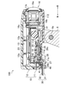
カメラ100は、図2に示すように、該カメラ100を構成する複数の構成部品(後述する回路基板17や電気配線30の一部等)を収容する筐体10を有している。該筐体10は、上側に開口しかつ内部に上記構成部品が組み付けられる筐体本体11と、該筐体本体11内に上記構成部品が組み付けられた状態で、筐体本体11の開口を覆う蓋部12とを有している。筐体本体11の開口の周縁部と蓋部12との間には、筐体内部13に水などの液体が浸入することを防止するためのシール部材14が、上記筐体本体11の開口の周縁部に沿って配設されている。筐体本体11と蓋部12とは、複数(本実施形態では4つ)のボルト90によって結合されている。筐体本体11及び蓋部12は、例えば樹脂で構成されている。
As shown in FIG. 2, the
筐体本体11の内部(つまり筐体内部13)には、図2に示すように、上記構成部品としての、レンズユニット16と、回路基板17と、スピーカ18とが組み付けられている。また、筐体本体11の内部には、飛行体本体2の上記駆動システムと回路基板17に設けられた回路とを電気的に接続する複数(本実施形態では7つ)の電気配線30の一部が収容される。
As shown in FIG. 2, a
レンズユニット16は、図2及び図4に示すように、筐体本体11に形成されたレンズ孔11bからレンズ16aが突出するように、筐体本体11の前壁部111(図4参照)にボルトによって組み付けられる。詳細には図示していないが、レンズ孔11bの周縁部とレンズユニット16との間には、筐体内部13に液体が浸入することを防止するためのシール部材が配設されている。
As shown in FIGS. 2 and 4, the
レンズユニット16内には、イメージセンサ等からなる撮像素子16b(図4参照)が設けられており、レンズ16aによる結像は撮像素子16bによって電気信号に変換される。撮像素子16bと回路基板17とは、フラットケーブル16cによって電気的に接続されており、撮像素子16bから出力された電気信号は電回路基板17に設けられた回路に伝達される。
An
レンズユニット16のレンズ16aとは反対側の部分には、レンズユニット16を保護するためのレンズ保護シート19が取り付けられている。
A
回路基板17は、図2に示すように、基板ホルダ20を介して、筐体本体11の内部に組み付けられている。具体的には、基板ホルダ20は、複数(本実施形態では3つ)のボルト91が、基板ホルダ20に形成された複数(ボルト91の数に対応して、本実施形態では3つ)のボルト孔を通って、筐体本体11の底壁部112に形成された複数(ボルト91の数に対応して、本実施形態では3つ)のボス部21に、それぞれ締結されることで、筐体本体11に組み付けられている。そして、回路基板17は、複数(本実施形態では4つ)のボルト92が、回路基板17に形成された複数(ボルト92の数に対応して、本実施形態では4つ)のボルト孔を通って、基板ホルダ20に形成された複数(ボルト92の数に対応して、本実施形態では4つ)のボス部20aに、それぞれ締結されることで、基板ホルダ20を介して筐体本体11に組み付けられている。
As shown in FIG. 2, the
筐体本体11に設けられたボス部21は、基板ホルダ20と筐体本体11の底壁部112(図4参照)との間に隙間が形成されるように、筐体本体11の底壁部112から上側に向かって突出するように形成されている。詳しくは後述するが、基板ホルダ20と筐体本体11の底壁部112との間の隙間には、スピーカ18が配設されたり、複数の電気配線30のうちの後述する起動用電気配線31が通ったりしている。
The
回路基板17上には、図2に示すように、メイン集積回路17aを含む、回路を構成する複数の電子部品が配置されている。回路基板17の回路が形成された側の面(つまり、回路基板17の表面)における、メイン集積回路17aを除く部分は、通電保護シート22で覆われている。この通電保護シート22は、上記電子部品と後述する放熱シート23とが接触して、上記電子部品と放熱シート23との間で通電するのを防止するための保護シートである。メイン集積回路17aは、放熱シート23の一端を貼り付ける必要があるため、通電保護シート22で覆われていない。
As shown in FIG. 2, a plurality of electronic components constituting the circuit, including the main
また、回路基板17には、上記複数の電気配線30が、半田付け等によって、それぞれ接続されている。
Further, the plurality of
さらに、図示は省略しているが、回路基板17の裏面における右後側の部分には、SDカードなどの記録媒体が挿し込まれるソケットが、挿入口が右側を向くように結合されている。該ソケットは、回路基板17が筐体本体11に組み付けられた状態で、上記挿込口が、筐体本体11の右側の側壁部113に形成されたソケット孔11cに位置するように回路基板17に配置されている。ソケット孔11cは、上記ソケットの挿込口に記録媒体を挿し込むとき以外は、基本的に、ソケット側カバー24によって、筐体10の外側から覆われるようになっている。上記ソケットは、上記複数の電気配線30とは別の電気配線によって回路基板17の回路と電気的に接続されている。尚、ソケット側カバー24は、ボルト93によって、筐体本体11に組み付けられている。
Further, although not shown, a socket into which a recording medium such as an SD card is inserted is coupled to a right rear portion on the back surface of the
放熱シート23は、一端がメイン集積回路17aの表面に貼り付けられる一方、図4に示すように、他端が蓋部12の筐体内部13側の面(以下、内側面という)に沿って貼り付けられている。蓋部12の内側面には、幅方向に延びかつ前後方向に互いに離間した2つのリブ12aが形成されており、放熱シート23における各リブ12aに対応する部分には、図2に示すように、スリット23aがそれぞれ形成されている。これにより、放熱シート23は、各リブ12aを避けるようにして、蓋部12の内側面の全面に貼り付けられる。放熱シート23は、例えば、グラファイトで構成されている。
One end of the
メイン集積回路17aの熱は、放熱シート23を介して蓋部12に伝達されて、該蓋部12から筐体外部に放出される。これにより、メイン集積回路17aの放熱が行われる。
The heat of the main
スピーカ18は、例えば、上記記録媒体の上記ソケットへの挿し込みが弱いとき等に、飛行体1の操縦者等に対して警告音を鳴らす際に用いられるものである。スピーカ18は、図2~図4に示すように、筐体本体11に形成された円筒状のスピーカ取付部11d内に嵌合されて、該筐体本体11に組み付けられている。より詳しくは、図4に示すように、スピーカ18は、スピーカ取付部11dに嵌合するように配置された状態で、上側から基板ホルダ20が載置されて、該基板ホルダ20に押さえ付けられることで、筐体本体11に組み付けられる。
The
スピーカ18からは、図3に示すように、スピーカ用電気配線18aが2本延びている。各スピーカ用電気配線18aは、一端がスピーカ18に接続され、他端が回路基板17に接続されている。これにより、スピーカ18と回路基板17の回路とが電気的に接続される。
As shown in FIG. 3, two
筐体本体11の底壁部112におけるスピーカ取付部11dの部分には、図4に示すように、スピーカ18からの警告音等が筐体外部に伝達されやすくするための音孔11eが開孔している。この音孔11eは、筐体外部からスピーカ側防滴シール25によって覆われている。このスピーカ側防滴シール25は、筐体10よりも振動を伝達しやすい材料で構成されており、上記音孔11eをスピーカ側防滴シール25で覆ったとしても、上記音孔11eを形成しない場合よりも、スピーカ18からの警告音等が筐体外部に伝達されやすいようになっている。
As shown in FIG. 4, a
上記複数の電気配線30は、図4に示すように、一端は回路基板17に接続される一方、他端は、筐体本体11の底壁部112に形成された嵌合孔11aを通って、筐体外部に露出している。そして、複数の電気配線30の他端は、飛行体本体2の駆動システム(図示省略)に接続される。
As shown in FIG. 4, one end of the plurality of
複数の電気配線30は、大きく分けて2つの配線群に分けられ、一方の配線群はカメラ100の起動用であり、他方の配線群はカメラ100の起動を除く制御用である。本実施形態では、起動用の配線群は2本の電気配線30で構成され、制御用の配線群は5本の電気配線30で構成されている。以下、起動用の2本の電気配線30を起動用電気配線31といい、制御用の5本の電気配線30を制御用電気配線32という。尚、これらを区別しないときには、単に電気配線30という。
The plurality of
2本の起動用電気配線31は、図3及び図4に示すように、それぞれ、嵌合孔11aを通って筐体内部13に入った後、スピーカ取付部11dの横を通って前側に向かって延びて、レンズユニット16の近傍で上側に向かって延びて、回路基板17に接続されている。5本の制御用電気配線32は、それぞれ、嵌合孔11aを通って筐体内部13に入った後、上側に向かって延びて、回路基板17に接続されている。
As shown in FIGS. 3 and 4, the two start-up
筐体10の嵌合孔11aには、複数の電気配線30の全てを貫通保持するとともに、筐体内部13に液体が浸入するのを防止して、筐体内部13の防滴性を確保するための防滴コネクタ40が嵌合されている。該防滴コネクタ40は、図3、図4及び図6~図8に示すように、筐体10の嵌合孔11aに嵌合される筒状部材42と、複数の電気配線30の全てを貫通保持するための配線保持部41とを有している。防滴コネクタ40は、シリコン樹脂などの弾性変形可能な部材で構成されている。つまり、防滴コネクタ40を構成する筒状部材42及び配線保持部41は、シリコン樹脂などの弾性変形可能な部材で構成されている。
The
筒状部材42は、図3及び図6に示すように、断面矩形状の角筒状をなしている。筒状部材42は、嵌合孔11aに嵌合していない状態において、該筒状部材42の筒軸方向から見た形状が、嵌合孔11aよりも大きい該嵌合孔11aの相似形をなすように構成されている。具体的には、筒状部材42が嵌合孔11aに嵌合していない状態において、筒状部材42の断面の長手方向(左右方向に相当)の寸法は、嵌合孔11aの長手方向(左右方向に相当)の寸法よりも大きく、筒状部材42の断面の短手方向(前後方向に相当)の寸法も、嵌合孔11aの短手方向(前後方向に相当)の寸法よりも大きい。つまり、筒状部材42は、上記筒軸方向の一部、具体的には、嵌合孔11aと同じ高さ位置に位置する部分が、筒内側に向かって均一に縮小するように変形して、嵌合孔11aと嵌合している。
As shown in FIGS. 3 and 6, the
筒状部材42は、図4及び図8に示すように、上記筒軸方向の長さが、筐体本体11の底壁部112における嵌合孔11aの部分の厚みよりも大きくなるように構成されている。これにより、筒状部材42が嵌合孔11aに嵌合した際には、筒状部材42の一部が筐体内部13に位置するようになる。
As shown in FIGS. 4 and 8, the
配線保持部41は、図4及び図6~図8に示すように、筒状部材42の筒内に設けられており、筒状部材42の形状に対応して、矩形板状をなしている。配線保持部41は、筒状部材42と一体形成されている。これにより、配線保持部41は、図4及び図8に示すように、筒状部材42が筐体10の嵌合孔11aに嵌合したときに、該筒状部材42を介して筐体10に組み付けられるようになっている。尚、配線保持部41は、板状ではなく、柱状であってもよい。
As shown in FIGS. 4 and 6 to 8, the
配線保持部41には、図6~図8に示すように、複数の電気配線30を上記筒軸方向に通過させて貫通保持するための複数の貫通孔43を有している。本実施形態では、複数の貫通孔43は、電気配線30の本数に合わせて7つ形成されている。より具体的には、筒状部材42が嵌合孔11aに嵌合した状態で、配線保持部41の相対的に前側に位置する部分には、2本の起動用電気配線31をそれぞれ貫通保持する2つの前側貫通孔43aが形成され、配線保持部41の相対的に後側に位置する部分には、5本の制御用電気配線32をそれぞれ貫通保持する5つの後側貫通孔43bが形成されている。これにより、図3及び図4に示すように、各起動用電気配線31を前側に延びるように配線する際に、各制御用電気配線32を避ける必要がなくなり、各起動用電気配線31の配線が容易になる。
As shown in FIGS. 6 to 8, the
各貫通孔43の直径は、通る配線の直径に対応して異なる大きさに設定されている。具体的には、本実施形態では、起動用電気配線31は、制御用電気配線32よりも太い(直径が大きい)ため、前側貫通孔43aは、後側貫通孔43bに比べて大径になっている。尚、後述するように、本実施形態では、筒状部材42が嵌合孔11aに嵌合した際に、各貫通孔43が縮径するように構成されているが、各貫通孔43の縮径後であっても、前側貫通孔43aの直径は、後側貫通孔43bの直径よりも大きくなる。
The diameter of each through
また、配線保持部41は、図4及び図8に示すように、筒状部材42が嵌合孔11aに嵌合した状態で、該筒状部材42の筒軸方向において、少なくとも一部(本実施形態では全部)が筐体本体11の底壁部112と同じ高さに位置するように、筒状部材42の筒内における上記筒軸方向の中間部分に位置している。詳しくは後述するが、配線保持部41が上述のように筒状部材42の筒内に位置していることで、筒状部材42が嵌合孔11aに嵌合した際に、配線保持部41における上記底壁部112と同じ高さ位置の部分が、上記筒軸方向に対して直交する方向に圧縮されて、複数の貫通孔43における上記底壁部112と同じ高さ位置の部分がそれぞれ縮径するようになる。
Further, as shown in FIGS. 4 and 8, the
さらに、配線保持部41が、上述のように筒状部材42の筒内に位置していることで、図6~図8に示すように、防滴コネクタ40の上記筒軸方向の筐体内部13側に第1凹部44が形成されている。また、防滴コネクタ40の上記筒軸方向の筐体内部13とは反対側にも第2凹部45が形成されている。言い換えると、配線保持部41は、筒状部材42と協働して、上記筒軸方向の筐体内部13側(本実施形態では上側)に第1凹部44が形成されるとともに、上記筒軸方向の筐体内部13とは反対側に第2凹部45が形成されるように、筒状部材42の筒内に位置している。第1凹部44及び第2凹部45のうち、少なくとも第1凹部44には、筒状部材42が嵌合孔11aに嵌合した後に、図9に示すように、接着剤Aが充填される。これにより、筐体内部13の防滴性を向上させるとともに、筒状部材42が嵌合孔11aに嵌合した後に、電気配線30が筐体内部13から引っ張り出されにくいようにしている。
Further, since the
図4、図7及び図8に示すように、筒状部材42の筒軸方向における筐体内部13とは反対側(本実施形態では下側)の端部には、筒状部材42の該端部から上記筒軸方向に対して直交する方向の外側に向かって延びるフランジ46が、筒状部材42と一体に設けられている。このフランジ46も、筒状部材42等と同様に、シリコン樹脂などの弾性部材で構成されている。フランジ46は、図4に示すように、筒状部材42が嵌合孔11aに嵌合した状態において、筐体本体11の底壁部112における嵌合孔11aの周縁に沿って設けられた嵌合凹部11f(図4では一部のみ示す)に嵌合されている。フランジ46には、嵌合凹部11fと接触する面に、防滴用の両面テープ28(図2参照)が貼り付けられており、これにより、筒状部材42が嵌合孔11aに嵌合して、配線保持部41が筐体10に組み付けられた状態で、防滴コネクタ40が筐体本体11から抜き取られにくくなるとともに、フランジ43と上記嵌合凹部11fとの間を通って、筐体内部13に液体が浸入することを防止して、筐体内部13の防滴性を向上させている。
As shown in FIGS. 4, 7 and 8, the
筐体本体11の底壁部112には、図2及び図4に示すように、筒状部材42が、各電気配線30が配線保持部41の各貫通孔43に貫通保持された状態で、嵌合孔11aに嵌合されるとともに、音孔11eがスピーカ側防滴シール25によって塞がれた状態で、底側カバー26が取り付けられる。底側カバー26は、複数(本実施形態では4つ)のボルト94によって、筐体本体11の底壁部112に取り付けられる。
As shown in FIGS. 2 and 4, the
底側カバー26には、図2に示すように、各電気配線30が通る配線通過孔26aが形成されている。配線通過孔26aの周囲には、筐体内部13側に向かって突出する突出部26bが、配線通過孔26aの周縁部に沿うように形成されている。この突出部26bは、図4に示すように、底側カバー26が、筐体本体11の底壁部112に取り付けられた状態で、フランジ46を底壁部112(厳密には底壁部112の嵌合凹部11fの部分)に向かって押圧するようになっている。これにより、フランジ46と嵌合凹部11fとの間に隙間が形成されにくくなり、筐体内部13の防滴性が向上される。
As shown in FIG. 2, the
底側カバー26の、突出部26bとは反対側の面には、図4及び図5に示すように、配線通過孔26aを通って、筐体外部に露出した各電気配線30を、後側に向かって案内するための配線ガイド部27が形成されている。配線ガイド部27の後側の壁部における幅方向の中央には、図5に示すように、上側から下側に向かって凹んだ凹部27aが形成されている。配線ガイド部27の凹部27aは、筐体本体11の底壁部112における後側の端部に設けられた配線押さえ部11gと協働して、配線ガイド部27によって後側に延びるように案内された各電気配線30を上下方向に押さえている。これにより、各電気配線30は、後側に引っ張られたとしても、筐体内部13から引っ張り出されにくくなっている。
On the surface of the
また、底側カバー26には、図4に示すように、スピーカ18からの警告音等が筐体外部に伝達されやすいようにする複数(本実施形態では7つ)の音孔26cが形成されている。
Further, as shown in FIG. 4, the
また、筐体本体11の底壁部112には、図2に示すように、筐体内部13の気圧を調整するための、内部気圧調整シール29が取り付けられている。内部気圧調整シール29には、孔が設けられているが、この孔の径は、空気を通過させる一方、水は通過させないような径に設定されており、内部気圧調整シール29の孔を通って、筐体内部13に水が浸入することは防止されている。
Further, as shown in FIG. 2, an internal air
ここで、本実施形態のカメラ100のように、主に外で使用される飛行体1に設けられるカメラは、雨天の中で使用されることがあるため、カメラ100の筐体10には高い防滴性が求められる。この高い防滴性を得るための防滴構造として、特に、防滴コネクタ40の構成が問題となる。これは、防滴コネクタ40については、カメラ100の組み立て後には、高い防滴性を得ることが求められる一方で、カメラ100の組み立て時においては、筐体内部13における各電気配線30の長さを調整するために、配線保持部41と各電気配線30との相対位置を調整できるようにすることが求められるためである。
Here, a camera provided in the flying object 1 mainly used outside, such as the
すなわち、仮に、各電気配線30を配線保持部41に予め固定するような構成とすると、各電気配線30における、回路基板17への接続部と配線保持部41との間の部分、つまり、筐体内部13に収容される部分が長くなり過ぎることがあり、筒状部材42を嵌合孔11aに嵌合させた際に(つまり、配線保持部41を筐体10に組み付けた際に)、筐体内部13で各電気配線30が撓んで、電気配線30と該回路基板17との接続部分に負荷がかかって、最悪の場合、各電気配線30と回路基板17の接続が切れてしまうおそれがある。また、各電気配線30を筐体内部13に収容しきれずに、配線保持部41の筐体10への組み付け自体が困難になるおそれもある。
That is, if each
これを防止するために、各電気配線30における筐体内部13に収容される部分の適切な長さを予め算出して、該算出結果に基づいて、各電気配線30の長さを予め決定することも考えられる。しかし、本実施形態のように、起動用電気配線31と制御用電気配線32とで、筐体内部13において必要な長さが異なっていたり、電気配線30(特に起動用電気配線31)を、スピーカ取付部11dなどを避けて配線したりする場合には、各電気配線30における筐体内部13に収容される部分の長さを予め決定することが困難である。したがって、組み立て時において、配線保持部41と各電気配線30との相対位置を調整できるようにすることが重要になる。
In order to prevent this, an appropriate length of the portion of each
そこで、本実施形態では、防滴コネクタ40の筒状部材42を、該筒状部材42が筐体10の嵌合孔11aに嵌合されたときに、配線保持部41を筒状部材42の筒軸方向に対して直交する方向に圧縮して、各貫通孔43を縮径させるように構成し、さらに、縮径後の各貫通孔43のそれぞれの直径が、各貫通孔43が縮径する前の各電気配線30の直径以下になるようにした。より詳しくは、貫通孔43内に電気配線30が位置していない状態において、筒状部材42が筐体10の嵌合孔11aに嵌合されて、貫通孔43が縮径したときの該貫通孔43の直径が、貫通孔43が縮径する前の電気配線30の直径以下となるようにした。
Therefore, in the present embodiment, the
この構成について、図7及び図8を参照しながら詳細に説明する。尚、以下の説明では、図7及び図8に示す、起動用電気配線31が通る前側貫通孔43aについて説明する。後側貫通孔43b及び制御用電気配線32は、以下に説明する、前側貫通孔43a及び起動用電気配線31と同様の変化をするため、詳細な説明を省略する。
This configuration will be described in detail with reference to FIGS. 7 and 8. In the following description, the front through
図7は、筒状部材42が筐体10の嵌合孔11aに嵌合される前の状態(つまり、配線保持部41が筐体10に組み付けられる前の状態)を示す。このときは、前側貫通孔43aの直径は、各起動用電気配線31の直径と同じか又は各起動用電気配線31の直径よりも僅かに大きい直径となっている。これにより、起動用電気配線31を引っ張り出して、配線保持部41と起動用電気配線31との相対位置を調整することができる。この結果、起動用電気配線31が接続された回路基板17が筐体本体11に組み付けられた後でかつ筒状部材42が合孔11aに嵌合された後の、筐体内部13における起動用電気配線31の長さを調整することができる。これにより、配線保持部41の筐体10への組み付けを容易にするとともに、筒状部材42が筐体10の嵌合孔11aに嵌合する際(つまり、配線保持部43を筐体10に組み付ける際)の起動用電気配線31への負荷の発生を抑えることができる。尚、起動用電気配線31は、導線31aと該導線31aを被覆する被覆部31bとで構成されており、起動用電気配線31の直径とは、被覆部31bを含む直径のことをいう。また、前側貫通孔43aの直径と起動用電気配線31の直径と同じ状態は、起動用電気配線31が前側貫通孔43aを貫通して、前側貫通孔43aが起動用電気配線31によって押し広げられた結果、前側貫通孔43aの直径と起動用電気配線31の直径とが同じになった場合を含む。
FIG. 7 shows a state before the
上述したように、筒状部材42は、嵌合孔11aに嵌合していない状態において、筒軸方向から見た形状が、嵌合孔11aよりも大きくなるように構成されているため、筒状部材42が筐体10の嵌合孔11aに嵌合すると、筒状部材42における、嵌合孔11aと同じ高さ位置に位置する部分が筒内側に向かって縮小する。一方で、配線保持部41は、嵌合孔11aに組み付けられた状態で、上記筒軸方向において、少なくとも一部が筐体本体11の底壁部112と同じ高さ位置に位置するように、筒状部材42の筒内における筒軸方向の中間部分に位置しているため、配線保持部41は、筒状部材42における筒内側に縮小した部分に位置することになる。これにより、配線保持部41は筒状部材42によって圧縮される。
As described above, the
そして、配線保持部41が圧縮される伴い、図8に示すように、前側貫通孔43aが縮径する。この縮径により、配線保持部41の前側貫通孔43aの内周縁部は、起動用電気配線31の被覆部31bに食い込もうとするが、起動用電気配線31からの反発により、図8に示すように、前側貫通孔43aの直径が起動用電気配線31の直径と同じになるように変形する。これにより、配線保持部41の前側貫通孔43aの内周縁部と起動用電気配線31の被覆部31bとが密着状態となり、筒状部材42が筐体10の嵌合孔11aに嵌合した後は、起動用電気配線31における前側貫通孔43a内に位置する部分と配線保持部41との間には隙間が形成されない。この結果、筒状部材42を筐体10の嵌合孔11aに嵌合させた後には、筐体内部13に液体が浸入することが防止されるため、高い防滴性を確保することができる。尚、縮径前(つまり、筒状部材42が嵌合孔11aに嵌合する前)の前側貫通孔43aの直径が、該前側貫通孔43aが縮径する前の起動用電気配線31の直径よりも大きくかつ、前側貫通孔43a内に起動用電気配線31が位置していない状態における、縮径後の前側貫通孔43aの直径が、前側貫通孔43aが縮径する前の起動用電気配線31の直径と同じである場合には、前側貫通孔43aは、起動用電気配線31からの反発による変形をすることなく、起動用電気配線31に密着することになる。
Then, as the
後側貫通孔43b及び制御用電気配線32は、それぞれの直径が、前側貫通孔43a及び起動用電気配線31と異なるだけで、上述の説明における、「前側貫通孔43a」を「後側貫通孔43b」と読み替え、「起動用電気配線31」を「制御用電気配線32」と読み替えればよい。
The diameters of the rear through
したがって、本実施形態では、筐体10の高い防滴性を確保しつつ、配線保持部43の筐体10へ組み付けを容易にするとともに、配線保持部41を筐体10へ組み付ける際の各電気配線30への負荷の発生を抑えることができる。
Therefore, in the present embodiment, while ensuring high drip-proof property of the
また、本実施形態では、筒状部材42は、該筒状部材42の筒軸方向から見た形状が、嵌合孔11aよりも大きい該嵌合孔11aの相似形をなしているため、筒状部材42が嵌合孔11aに嵌合したときには、筒上部材42は筒内側に均一に縮小する。これにより、配線保持部41が均一に圧縮され、貫通孔43も均一に縮径するため、電気配線30における貫通孔30内に位置する部分と配線保持部41との間には、一層隙間が形成されにくくなる。この結果、筐体10の防滴性をより向上させることができる。
Further, in the present embodiment, the
さらに、本実施形態では、配線保持部41は、筒状部材42と協働して、配線保持部41の筐体10への組付方向の筐体内部13側(本実施形態では上側)に、第1凹部44が形成されるように構成されているため、筒状部材42における第1凹部44を構成する部分は、筐体10の嵌合孔11aを通って該筐体内部13に挿入しやすいように変形させることができる。これにより、筒状部材42における第1凹部44を構成する部分を筐体内部13に挿入すれば、筒状部材42の残りの部分を、嵌合孔11aの周縁に沿わせながら容易に筐体内部13に挿入することができる。これにより、配線保持部41の組み付けを一層容易にすることができる。
Further, in the present embodiment, the
また、図9に示すように、配線保持部41を筐体10に組み付けた後に、第1凹部44内に接着剤Aを充填させれば、筐体内部13の防滴性を向上させるとともに、配線保持部41を筐体10に組み付けた後に、電気配線30が筐体内部13から引っ張り出されにくいようにすることができる。
Further, as shown in FIG. 9, if the
さらに、本実施形態では、カメラ100は、該カメラ100の筐体10に設けられた嵌合孔11aが下側に位置するように、飛行体本体2に取り付けられているため、例えば、雨天の中で飛行体1を動作させたとしても、筐体内部13に雨水が浸入しにくいようにすることができる。
Further, in the present embodiment, the
したがって、本実施形態では、筐体10に形成された嵌合孔11aに嵌合される、弾性変形可能な筒状の筒状部材42と、該筒状部材42の筒内に固定され、電気配線30を筒状部材42の筒軸方向に通過させて貫通保持するための貫通孔43を有し、弾性変形可能な板状の配線保持部41とを備え、筒状部材42は、上記筒軸方向から見た形状が筐体10の嵌合孔11aよりも大きくなるように形成されるとともに、筐体10の嵌合孔11aに嵌合されたときに、配線保持部41を上記筒軸方向に対して直交する方向に圧縮して、貫通孔43を縮径させるように構成されており、該縮径後の貫通孔43の直径は、貫通孔43が縮径する前の電気配線30の直径以下であるため、筐体10の高い防滴性を確保しつつ、配線保持部41の筐体10へ組み付けを容易にするとともに、配線保持部41を筐体10へ組み付ける際の各電気配線30への負荷の発生を抑えることができる。
Therefore, in the present embodiment, the elastically deformable
本発明は、上記実施形態に限られるものではなく、請求の範囲の主旨を逸脱しない範囲で代用が可能である。 The present invention is not limited to the above embodiment, and can be substituted as long as it does not deviate from the gist of the claims.
例えば、上述の実施形態では、該貫通孔43の内周縁部が、電気配線30からの反発力によって、貫通孔43の直径が電気配線30の直径と同じになるように変形していたが、これに限らず、貫通孔43が縮径した際に、該貫通孔43の内周縁部が、電気配線30の被覆部に食い込んでもよい。この場合、貫通孔43内に電気配線30が位置している場合でも、縮径後の貫通孔43の直径が、貫通孔43が縮径する前の電気配線30の直径よりも小さくなる。この場合でも、貫通孔43の内周縁部と電気配線30とが密着状態となり、電気配線30における貫通孔43内に位置する部分と配線保持部41との間には、隙間が形成されないため、筐体10の高い防滴性を得ることができる。
For example, in the above-described embodiment, the inner peripheral edge portion of the through
また、上述の実施形態では、第1凹部44にのみ接着剤を充填していたが、これに限らず、第2凹部45にも接着剤を充填するようにしてもよい。これにより、筐体10の防滴性を更に向上させることができる。
Further, in the above-described embodiment, the adhesive is filled only in the
さらに,上述の実施形態では、電気配線30が複数あるものの筐体10に対して、本発明の防滴構造を適用していたが、これに限らず、電気配線30が1本のみのものに対しても適用することができる。
Further, in the above-described embodiment, the drip-proof structure of the present invention is applied to the
また、上述の実施形態では、配線保持部41と筒状部材42とを一体形成していたが、これに限らず、配線保持部41と筒状部材42とを別体で構成してもよい。このとき、配線保持部41は、筒状部材42の筒内に接着剤等で固定することが望ましい。この構成では、配線保持部41と筒状部材42とで、弾性係数の異なる部材を用いることができるようになる。
Further, in the above-described embodiment, the
さらに、上述の実施形態では、筐体10の嵌合孔11aは矩形状であったが、他の多角形状や円形状であってもよい。この場合には、防滴コネクタ40の配線保持部41及び筒状部材42も、嵌合孔11aの形状に対応して形状を変える必要がある。
Further, in the above-described embodiment, the
また、上述の実施形態では、筒状部材42は、該筒状部材42の筒軸方向から見た形状が、嵌合孔11aの相似形をなしていたが、これに限らず、電気配線30における貫通孔43内に位置する部分と配線保持部41との間に隙間が形成されることを防止することができれば、筒状部材42の、上記筒軸方向から見た形状が、嵌合孔11aの相似形をなしていなくともよい。ただし、貫通孔43を均一に縮径させるためには、筒状部材42の、上記筒軸方向から見た形状が、嵌合孔11aの相似形をなしていることが望ましい。
Further, in the above-described embodiment, the
上述の実施形態は単なる例示に過ぎず、本発明の範囲を限定的に解釈してはならない。本発明の範囲は請求の範囲によって定義され、請求の範囲の均等範囲に属する変形や変更は、全て本発明の範囲内のものである。 The above embodiments are merely examples, and the scope of the present invention should not be construed in a limited manner. The scope of the present invention is defined by the scope of the claims, and all modifications and modifications belonging to the equivalent scope of the claims are within the scope of the present invention.
本発明は、内部に電気配線の一部を収容する筐体の該筐体内部に液体が浸入するのを防止するとともに、電気配線が筐体内部から筐体外部に露出する部分において電気配線を貫通保持するための、筐体の防滴構造として有用である。 The present invention prevents liquid from entering the inside of the housing that houses a part of the electrical wiring inside, and provides the electrical wiring in the portion where the electrical wiring is exposed from the inside of the housing to the outside of the housing. It is useful as a drip-proof structure of the housing for penetrating and holding.
1 飛行体
10 筐体
11a 嵌合孔(孔部)
13 筐体内部
30 電気配線
41 配線保持部
42 筒状部材
43 貫通孔
44 第1凹部(筒軸方向の筐体内部側に形成された凹部)
A 接着剤
1
13 Inside the
A adhesive
Claims (5)
上記電気配線は複数あり、
上記筐体に形成された孔部に嵌合される、弾性変形可能な筒状の筒状部材と、
上記筒状部材の筒内に該筒状部材と一体形成され、上記各電気配線を上記筒状部材の筒軸方向に通過させてそれぞれ貫通保持するための複数の貫通孔を有し、弾性変形可能な1つの柱状又は板状の部材で構成された配線保持部と、を備え、
上記筒状部材は、上記筒軸方向から見た形状が、上記孔部よりも大きい形状をなすとともに、上記筐体の上記孔部に嵌合されたときに、上記配線保持部を上記筒軸方向に対して直交する方向に圧縮して、上記各貫通孔をそれぞれ縮径させるように構成されており、
上記縮径後の上記各貫通孔の直径は、それぞれ、上記貫通孔が縮径する前の、当該貫通孔に挿通された上記電気配線の直径以下であることを特徴とする筐体の防滴構造。 While preventing liquid from entering the inside of the housing that houses a part of the electrical wiring inside, the electrical wiring is penetrated and held at the portion where the electrical wiring is exposed from the inside of the housing to the outside of the housing. It is a drip-proof structure of the housing for
There are multiple electrical wirings mentioned above,
An elastically deformable tubular member fitted in the hole formed in the housing, and
It is integrally formed with the tubular member in the cylinder of the tubular member, and has a plurality of through holes for passing each of the electrical wirings in the cylindrical axial direction of the tubular member and holding them through, respectively , and is elastically deformed. With a wiring holder made of one possible columnar or plate-like member ,
The tubular member has a shape larger than the hole portion when viewed from the cylinder axis direction, and when fitted into the hole portion of the housing, the wiring holding portion is attached to the cylinder shaft. It is configured to reduce the diameter of each of the above-mentioned through holes by compressing in a direction orthogonal to the direction.
The diameter of each of the through holes after the diameter reduction is not less than the diameter of the electrical wiring inserted through the through holes before the through holes are reduced in diameter, respectively. Construction.
上記筒状部材は、上記筒軸方向から見た形状が、上記孔部よりも大きい該孔部の相似形をなしていることを特徴とする筐体の防滴構造。 In the drip-proof structure of the housing according to claim 1 ,
The tubular member is a drip-proof structure of a housing, characterized in that the shape seen from the tubular axis direction is similar to the hole portion larger than the hole portion.
上記配線保持部は、上記筒状部材と協働して、上記筒軸方向の上記筐体内部側に凹部が形成されるように、上記筒状部材内に位置していることを特徴とする筐体の防滴構造。 In the drip-proof structure of the housing according to claim 1 or 2 .
The wiring holding portion is characterized in that it is located in the tubular member in cooperation with the tubular member so that a recess is formed on the inner side of the housing in the cylindrical axial direction. Drip-proof structure of the housing.
上記凹部内には接着剤が充填されていることを特徴とする筐体の防滴構造。 In the drip-proof structure of the housing according to claim 3 ,
A drip-proof structure of a housing characterized in that the recesses are filled with an adhesive.
上記筐体は、飛行体に取り付けられるカメラの筐体であり、
さらに上記筐体は、上記孔部が下側に位置するように上記飛行体に取り付けられていることを特徴とする筐体の防滴構造。 In the drip-proof structure of the housing according to any one of claims 1 to 4 .
The above housing is the housing of the camera attached to the flying object.
Further, the housing is a drip-proof structure of the housing, characterized in that the housing is attached to the flying object so that the hole is located on the lower side.
Priority Applications (1)
| Application Number | Priority Date | Filing Date | Title |
|---|---|---|---|
| JP2017140758A JP7009099B2 (en) | 2017-07-20 | 2017-07-20 | Drip-proof structure of the housing |
Applications Claiming Priority (1)
| Application Number | Priority Date | Filing Date | Title |
|---|---|---|---|
| JP2017140758A JP7009099B2 (en) | 2017-07-20 | 2017-07-20 | Drip-proof structure of the housing |
Related Child Applications (1)
| Application Number | Title | Priority Date | Filing Date |
|---|---|---|---|
| JP2020073377A Division JP2020127030A (en) | 2020-04-16 | 2020-04-16 | Flying vehicle drip-proof structure |
Publications (2)
| Publication Number | Publication Date |
|---|---|
| JP2019021830A JP2019021830A (en) | 2019-02-07 |
| JP7009099B2 true JP7009099B2 (en) | 2022-01-25 |
Family
ID=65355903
Family Applications (1)
| Application Number | Title | Priority Date | Filing Date |
|---|---|---|---|
| JP2017140758A Active JP7009099B2 (en) | 2017-07-20 | 2017-07-20 | Drip-proof structure of the housing |
Country Status (1)
| Country | Link |
|---|---|
| JP (1) | JP7009099B2 (en) |
Citations (5)
| Publication number | Priority date | Publication date | Assignee | Title |
|---|---|---|---|---|
| JP2004515189A (en) | 2000-11-24 | 2004-05-20 | ビール エンジニアリング ビー.ブイ. | bush |
| JP2006156094A (en) | 2004-11-29 | 2006-06-15 | Kawamoto Pump Mfg Co Ltd | Cord bush |
| JP2012223067A (en) | 2011-04-14 | 2012-11-12 | Yaskawa Electric Corp | Motor control device and bushing of the same |
| JP2017016388A (en) | 2015-07-01 | 2017-01-19 | 株式会社日本総合研究所 | Areal album creation server and creation method thereof |
| JP2017036988A (en) | 2015-08-10 | 2017-02-16 | クモノスコーポレーション株式会社 | Photographing system |
Family Cites Families (3)
| Publication number | Priority date | Publication date | Assignee | Title |
|---|---|---|---|---|
| US3322890A (en) * | 1966-03-31 | 1967-05-30 | Jacobs Mfg Co | Bushing-seal |
| JP3291674B2 (en) * | 1995-06-06 | 2002-06-10 | 住友電装株式会社 | Grommets for gas seals |
| JP3334492B2 (en) * | 1996-05-28 | 2002-10-15 | 住友電装株式会社 | Grommet |
-
2017
- 2017-07-20 JP JP2017140758A patent/JP7009099B2/en active Active
Patent Citations (5)
| Publication number | Priority date | Publication date | Assignee | Title |
|---|---|---|---|---|
| JP2004515189A (en) | 2000-11-24 | 2004-05-20 | ビール エンジニアリング ビー.ブイ. | bush |
| JP2006156094A (en) | 2004-11-29 | 2006-06-15 | Kawamoto Pump Mfg Co Ltd | Cord bush |
| JP2012223067A (en) | 2011-04-14 | 2012-11-12 | Yaskawa Electric Corp | Motor control device and bushing of the same |
| JP2017016388A (en) | 2015-07-01 | 2017-01-19 | 株式会社日本総合研究所 | Areal album creation server and creation method thereof |
| JP2017036988A (en) | 2015-08-10 | 2017-02-16 | クモノスコーポレーション株式会社 | Photographing system |
Also Published As
| Publication number | Publication date |
|---|---|
| JP2019021830A (en) | 2019-02-07 |
Similar Documents
| Publication | Publication Date | Title |
|---|---|---|
| JP7321752B2 (en) | motor unit | |
| WO2015194666A1 (en) | Electrical junction box and connector housing | |
| JP7098778B2 (en) | Unmanned aircraft equipped with electronic devices | |
| JP6863662B2 (en) | Aerial camera and electronic equipment and unmanned aerial vehicle equipped with it | |
| JP6390531B2 (en) | Housing member and in-vehicle electronic device using the same | |
| JP2008022653A (en) | Controller for electric motor and motor-operated power steering system | |
| JP2018189773A (en) | On-vehicle camera | |
| JP6893905B2 (en) | Housing and wire harness | |
| JP7009099B2 (en) | Drip-proof structure of the housing | |
| JP2016192888A (en) | Electronic control device | |
| JP4556651B2 (en) | Electronic control device, electric motor with electronic control device | |
| JP4792482B2 (en) | Fixing structure between radiator of motor control device and assembly parts | |
| JP7050463B2 (en) | Electronic control device | |
| JP6458715B2 (en) | Electronic control unit | |
| JP2020127030A (en) | Flying vehicle drip-proof structure | |
| JP2006054324A (en) | Electric connection line fixing device and recorder provided with the same | |
| JP4644502B2 (en) | Substrate support device and image forming apparatus | |
| JP6847171B2 (en) | Electronic control device | |
| JP2001073829A (en) | Engine-integrated controller and circuit body used therefor | |
| JP2005318742A (en) | Electric motor | |
| US20240081030A1 (en) | Electric vehicle | |
| KR102512858B1 (en) | Electronic control device | |
| US11418084B2 (en) | Generator | |
| JP2016188024A (en) | Electronic control device | |
| JP6310774B2 (en) | Mirror holder for vehicle |
Legal Events
| Date | Code | Title | Description |
|---|---|---|---|
| A621 | Written request for application examination |
Free format text: JAPANESE INTERMEDIATE CODE: A621 Effective date: 20200604 |
|
| A977 | Report on retrieval |
Free format text: JAPANESE INTERMEDIATE CODE: A971007 Effective date: 20210524 |
|
| A131 | Notification of reasons for refusal |
Free format text: JAPANESE INTERMEDIATE CODE: A131 Effective date: 20210601 |
|
| A521 | Request for written amendment filed |
Free format text: JAPANESE INTERMEDIATE CODE: A523 Effective date: 20210719 |
|
| TRDD | Decision of grant or rejection written | ||
| A01 | Written decision to grant a patent or to grant a registration (utility model) |
Free format text: JAPANESE INTERMEDIATE CODE: A01 Effective date: 20211214 |
|
| A61 | First payment of annual fees (during grant procedure) |
Free format text: JAPANESE INTERMEDIATE CODE: A61 Effective date: 20220112 |
|
| R150 | Certificate of patent or registration of utility model |
Ref document number: 7009099 Country of ref document: JP Free format text: JAPANESE INTERMEDIATE CODE: R150 |