JP7006550B2 - Emergency stop switch and robot system - Google Patents
Emergency stop switch and robot system Download PDFInfo
- Publication number
- JP7006550B2 JP7006550B2 JP2018176207A JP2018176207A JP7006550B2 JP 7006550 B2 JP7006550 B2 JP 7006550B2 JP 2018176207 A JP2018176207 A JP 2018176207A JP 2018176207 A JP2018176207 A JP 2018176207A JP 7006550 B2 JP7006550 B2 JP 7006550B2
- Authority
- JP
- Japan
- Prior art keywords
- identification code
- emergency stop
- mobile terminal
- stop switch
- processing unit
- Prior art date
- Legal status (The legal status is an assumption and is not a legal conclusion. Google has not performed a legal analysis and makes no representation as to the accuracy of the status listed.)
- Active
Links
Images


Description
本発明の実施形態は、非常停止スイッチ、及びロボットシステムに関する。 Embodiments of the present invention relate to an emergency stop switch and a robot system.
ISO10218等のロボットの安全規格によれば、ロボットの教示操作を行うための操作装置には、手動で始動可能な非常停止スイッチを設ける必要がある旨が定められている。そのため、いわゆるティーチングペンダントと称される従来の操作装置には、教示操作に用いるスイッチ等とは別に、手動で始動可能な機械式の非常停止スイッチが設けられている。 According to the safety standards of robots such as ISO10218, it is stipulated that the operating device for performing the teaching operation of the robot needs to be provided with an emergency stop switch that can be started manually. Therefore, the conventional operating device, so-called teaching pendant, is provided with a mechanical emergency stop switch that can be started manually, in addition to the switch used for the teaching operation.
一方、近年、従来のティーチングペンダントに代えて、操作装置としていわゆるスマートフォンやタブレット等の高機能携帯端末を用いることが行われている。このような携帯端末は、汎用品であってロボットの教示操作専用に設計されたものではないため、非常停止スイッチを備えていない。そのため、このような携帯端末をロボットの操作装置として使用するために、携帯端末に後から装着可能な非常停止スイッチが考えられている。そして、このような非常停止スイッチにおいては、安全性の面から、携帯端末をロボットの操作装置として使用するときに携帯端末に確実に装着されていることが重要である。 On the other hand, in recent years, instead of the conventional teaching pendant, a high-performance mobile terminal such as a so-called smartphone or tablet has been used as an operating device. Since such a mobile terminal is a general-purpose product and is not designed exclusively for the teaching operation of the robot, it does not have an emergency stop switch. Therefore, in order to use such a mobile terminal as an operating device for a robot, an emergency stop switch that can be attached to the mobile terminal later has been considered. In such an emergency stop switch, from the viewpoint of safety, it is important that the mobile terminal is securely attached to the mobile terminal when it is used as a robot operating device.
本発明は上記事情を鑑みてなされたものであり、その目的は、スマートフォンやタブレット装置等の携帯端末をロボットの操作装置として使用する場合にその携帯端末に確実に装着されているようにすることができる非常停止スイッチ、及びその非常停止スイッチを用いたロボットシステムを提供することにある。 The present invention has been made in view of the above circumstances, and an object of the present invention is to ensure that a mobile terminal such as a smartphone or tablet device is securely attached to the mobile terminal when it is used as an operation device of a robot. It is an object of the present invention to provide an emergency stop switch capable of being used, and a robot system using the emergency stop switch.
(請求項1)
請求項1に記載の非常停止スイッチは、ロボットの駆動を制御するロボットコントローラに有線接続されユーザの操作を受けて前記ロボットコントローラの制御を非常停止状態に切り替えるスイッチ本体部と、ユーザの操作を受け付ける携帯端末に対して前記スイッチ本体部を着脱可能に取り付ける取付部と、前記取付部を前記携帯端末に取り付けた場合に前記携帯端末が備えるカメラのレンズに対向する位置に設けられ、前記スイッチ本体部を識別する識別コードを前記カメラで撮影可能な態様で表示する識別コード部と、を備える。
(Claim 1)
The emergency stop switch according to
これによれば、ユーザは、取付部によって、非常停止スイッチのスイッチ本体部をスマートフォンやタブレット端末等の携帯端末に着脱可能に容易に取り付けることができる。そして、取付部を携帯端末に取り付けた場合、携帯端末が備えるカメラのレンズに対向する位置には、識別コード部が位置する。すなわち、携帯端末のカメラで撮影した画像内に識別コード部が含まれていないということは、非常停止スイッチが携帯端末に正しく装着されていないことを意味する。 According to this, the user can easily attach and detach the switch main body portion of the emergency stop switch to a mobile terminal such as a smartphone or a tablet terminal by the mounting portion. When the attachment portion is attached to the mobile terminal, the identification code portion is located at a position facing the lens of the camera included in the mobile terminal. That is, the fact that the identification code portion is not included in the image taken by the camera of the mobile terminal means that the emergency stop switch is not correctly attached to the mobile terminal.
一方、携帯端末のカメラで撮影した画像内に識別コード部が含まれているということは、非常停止スイッチが携帯端末に正しく装着されていることを意味する。そのため、携帯端末又はロボットコントローラは、例えばカメラの撮影を一定間隔で実行し、その撮影した画像内に識別コード部が含まれているか否かによって、非常停止スイッチが携帯端末に装着されているか否かを判断することができる。このように、本発明によれば、スマートフォンやタブレット装置等の携帯端末をロボットの操作装置として使用する場合に、その携帯端末に非常停止スイッチを確実に装着されているようにすることができる。 On the other hand, the fact that the identification code portion is included in the image taken by the camera of the mobile terminal means that the emergency stop switch is correctly attached to the mobile terminal. Therefore, the mobile terminal or the robot controller performs shooting by the camera at regular intervals, and whether or not the emergency stop switch is attached to the mobile terminal depending on whether or not the captured image includes an identification code unit. Can be determined. As described above, according to the present invention, when a mobile terminal such as a smartphone or a tablet device is used as an operation device for a robot, it is possible to ensure that the mobile terminal is equipped with an emergency stop switch.
(請求項2)
請求項2に記載の非常停止スイッチにおいて、前記取付部は、前記取付部を前記携帯端末に取り付けた場合に前記レンズから離間する方向へ突出した突出部を有している。そして、前記識別コード部は、前記突出部の内側に面に設けられている。
(Claim 2)
In the emergency stop switch according to claim 2, the mounting portion has a protruding portion protruding in a direction away from the lens when the mounting portion is mounted on the mobile terminal. The identification code portion is provided on the inner surface of the protruding portion.
これによれば、識別コード部が突出部の内側の面つまりカメラのレンズと対向する側の面に設けられていることから、非常停止スイッチを携帯端末に取り付けた場合において、カメラのレンズから識別コード部までの距離を確保し、その距離を一定に維持することができる。これにより、例えば識別コード部がカメラのレンズの焦点距離よりも接近し過ぎることを防ぎ、その結果、携帯端末のカメラによる識別コード部の撮影の精度を向上させることができる。 According to this, since the identification code portion is provided on the inner surface of the protruding portion, that is, the surface on the side facing the lens of the camera, when the emergency stop switch is attached to the mobile terminal, it is identified from the lens of the camera. The distance to the cord part can be secured and the distance can be kept constant. This prevents, for example, the identification code portion from being too close to the focal length of the lens of the camera, and as a result, it is possible to improve the accuracy of shooting the identification code portion by the camera of the mobile terminal.
(請求項3)
請求項3に記載の非常停止スイッチは、外部の光を前記識別コード部へ導入可能な採光部を更に備える。これによれば、採光部から識別コード部へ外光が導入されることによって、カメラの撮影に必要な光を確保することができる。そのため、本構成によれば、フラッシュやライト等の光源が無くても撮影に必要な光量を確保し易くなり、その結果、携帯端末のカメラによる識別コード部の撮影の精度、つまり識別コード部に含まれる識別コードの認識精度を向上することができる。
(Claim 3)
The emergency stop switch according to claim 3 further includes a daylighting unit capable of introducing external light into the identification code unit. According to this, by introducing the external light from the lighting unit to the identification code unit, it is possible to secure the light required for shooting by the camera. Therefore, according to this configuration, it becomes easy to secure the amount of light required for shooting even without a light source such as a flash or a light, and as a result, the accuracy of shooting of the identification code portion by the camera of the mobile terminal, that is, the identification code portion. It is possible to improve the recognition accuracy of the included identification code.
(請求項4)
ここで、例えば一つの作業現場に複数台のロボットが存在する場合、ユーザは、各ロボットに対応させて複数の非常停止スイッチを準備することが考えられる。この場合、各ロボットコントローラは、それぞれ自己に実際に有線接続された非常停止スイッチの識別コードを予め登録しておくことで、他のロボットに対応したロボットコントローラに接続された非常停止スイッチとの混同を防止することができる。この場合、ロボットコントローラに対する識別コードの登録は、例えばユーザが入力デバイスを用いて手作業で行うことが考えられるが、この登録作業を手作業で行うのは煩雑である。
(Claim 4)
Here, for example, when there are a plurality of robots in one work site, it is conceivable that the user prepares a plurality of emergency stop switches corresponding to each robot. In this case, each robot controller may be confused with the emergency stop switch connected to the robot controller corresponding to another robot by registering the identification code of the emergency stop switch actually connected by wire to itself in advance. Can be prevented. In this case, it is conceivable that the user manually registers the identification code for the robot controller, for example, using the input device, but it is complicated to manually perform this registration work.
そこで、請求項4に記載の非常停止スイッチは、前記識別コードを記憶する識別コード記憶部を更に備えるとともに、前記ロボットコントローラに有線接続された場合に前記識別コード記憶部に記憶されている前記識別コードが前記ロボットコントローラに自動で送信される。これによれば、ユーザが非常停止スイッチをロボットコントローラに接続するだけで、非常停止スイッチの識別コードが自動でロボットコントローラに登録される。そのため、ユーザは、非常停止スイッチの識別コードの登録作業が不要となり、その結果、利便性の向上を図ることができる。 Therefore, the emergency stop switch according to claim 4 further includes an identification code storage unit for storing the identification code, and the identification code stored in the identification code storage unit when connected to the robot controller by wire. The code is automatically transmitted to the robot controller. According to this, the user simply connects the emergency stop switch to the robot controller, and the identification code of the emergency stop switch is automatically registered in the robot controller. Therefore, the user does not need to register the identification code of the emergency stop switch, and as a result, the convenience can be improved.
(請求項5)
請求項5に記載のロボットシステムは、ロボットの駆動を制御するロボットコントローラと、カメラを有し前記ロボットコントローラと無線通信可能な携帯端末と、前記ロボットコントローラに有線接続されユーザの操作を受けて前記ロボットコントローラの制御を非常停止状態に切り替えるスイッチ本体部と、前記携帯端末に対して前記スイッチ本体部を着脱可能に取り付ける取付部と、前記カメラのレンズに対向する位置に設けられ前記スイッチ本体部を識別する識別コードを前記カメラで撮影可能な態様で表示する識別コード部と、を有する非常停止スイッチと、を備える。
(Claim 5)
The robot system according to claim 5 includes a robot controller that controls the drive of the robot, a mobile terminal that has a camera and is capable of wireless communication with the robot controller, and is connected to the robot controller by wire and is operated by a user. The switch body that switches the control of the robot controller to the emergency stop state, the mounting part that attaches and detaches the switch body to the mobile terminal, and the switch body that is provided at a position facing the camera lens. It includes an identification code unit for displaying the identification code in a manner that can be photographed by the camera, and an emergency stop switch having the identification code.
前記携帯端末は、当該携帯端末に前記非常停止スイッチが装着された場合に前記非常停止スイッチが備える前記識別コード部を前記カメラで撮影してその撮影した画像から前記識別コード部に含まれる識別コードを読み取る読取処理部と、前記読取処理部で読み取った前記識別コードを前記ロボットコントローラに送信する送信処理部と、を有する。前記ロボットコントローラは、前記ロボットコントローラに有線接続された前記非常停止スイッチの前記識別コードを前記カメラで前記識別コード部を撮影する方法とは異なる方法で取得する第1取得処理部と、前記携帯端末の前記送信処理部から送信された前記識別コードを取得する第2取得処理部と、前記第1取得処理部で取得した識別コードと前記第2取得処理部で取得した識別コードとが一致した場合に前記携帯端末からの操作に基づく前記ロボットの駆動を許可する許可判断処理部と、を有する。 When the mobile terminal is equipped with the emergency stop switch, the mobile terminal captures the identification code unit included in the emergency stop switch with the camera, and the identification code included in the identification code unit from the captured image. It has a reading processing unit for reading the above, and a transmission processing unit for transmitting the identification code read by the reading processing unit to the robot controller. The robot controller includes a first acquisition processing unit that acquires the identification code of the emergency stop switch that is wiredly connected to the robot controller by a method different from the method of photographing the identification code unit with the camera, and the mobile terminal. When the second acquisition processing unit that acquires the identification code transmitted from the transmission processing unit, the identification code acquired by the first acquisition processing unit, and the identification code acquired by the second acquisition processing unit match. It also has a permission determination processing unit that permits driving of the robot based on an operation from the mobile terminal.
これによれば、上述した非常停止スイッチを、スマートフォンやタブレット端末等の携帯端末に容易に適用させることができる。すなわち、携帯端末に非常停止スイッチを装着して操作装置として用いる場合、ロボットコントローラに実際に有線接続された非常停止スイッチと、携帯端末に実際に装着された非常停止スイッチとが同一のものであることを確認する必要がある。 According to this, the above-mentioned emergency stop switch can be easily applied to a mobile terminal such as a smartphone or a tablet terminal. That is, when the emergency stop switch is attached to the mobile terminal and used as an operation device, the emergency stop switch actually connected to the robot controller by wire and the emergency stop switch actually attached to the mobile terminal are the same. You need to make sure that.
例えばあるロボットコントローラに有線接続された非常停止スイッチが、そのロボットコントローラに対応した携帯端末とは異なる携帯端末に誤って装着されてしまった場合、ユーザは、非常停止スイッチを操作しても、目的とするロボットを非常停止させることができない。つまりこの場合、ユーザは、実質的に非常停止機能を有さない携帯端末を、操作装置として使用することになってしまうため、安全性に問題が生じる。そのため、携帯端末に非常停止スイッチを装着して操作装置として用いる場合、ロボットコントローラと、携帯端末と、非常停止スイッチとを相互に紐付けする必要がある。 For example, if an emergency stop switch connected to a robot controller by wire is accidentally attached to a mobile terminal different from the mobile terminal corresponding to the robot controller, the user can operate the emergency stop switch for the purpose. The robot cannot be stopped in an emergency. That is, in this case, the user ends up using a mobile terminal that does not have an emergency stop function as an operating device, which causes a safety problem. Therefore, when the emergency stop switch is attached to the mobile terminal and used as an operation device, it is necessary to link the robot controller, the mobile terminal, and the emergency stop switch to each other.
これに対し、本構成によれば、ロボットコントローラにおいて、第1取得処理部は、ロボットコントローラに有線接続された又は有線接続される非常停止スイッチの識別コードを取得する。これにより、ロボットコントローラは、第1取得処理部で取得した識別コードにより、ロボットコントローラと非常停止スイッチとの紐付けを行うことができる。また、第2取得処理部は、携帯端末に実際に装着された非常停止スイッチの識別コードを取得する。これにより、ロボットコントローラは、第2取得処理部で取得した識別コードにより、携帯端末と非常停止スイッチとの紐付けを行うことができる。 On the other hand, according to this configuration, in the robot controller, the first acquisition processing unit acquires the identification code of the emergency stop switch that is wiredly connected to or connected to the robot controller. As a result, the robot controller can associate the robot controller with the emergency stop switch by the identification code acquired by the first acquisition processing unit. In addition, the second acquisition processing unit acquires the identification code of the emergency stop switch actually mounted on the mobile terminal. As a result, the robot controller can associate the mobile terminal with the emergency stop switch by the identification code acquired by the second acquisition processing unit.
そして、許可判断処理部は、第1取得処理部で取得した識別コードと第2取得処理部で取得した識別コードとが一致した場合、つまりロボットコントローラに有線接続された非常停止スイッチと、携帯端末に装着された非常停止スイッチとが同一のものであると確認された場合に、携帯端末からの操作に基づくロボットの駆動を許可する。 Then, when the identification code acquired by the first acquisition processing unit and the identification code acquired by the second acquisition processing unit match, that is, the emergency stop switch wiredly connected to the robot controller and the mobile terminal are used in the permission determination processing unit. When it is confirmed that the emergency stop switch mounted on the device is the same, the robot is allowed to be driven based on the operation from the mobile terminal.
つまり、例えばあるロボットコントローラに有線接続された非常停止スイッチが、そのロボットコントローラに対応した携帯端末とは異なる携帯端末に誤って装着されてしまった場合には、携帯端末からの操作に基づくロボットの駆動は許可されない。このため、携帯端末に非常停止スイッチが装着されていなかったり、誤って他のロボットに対応した非常停止スイッチを装着してしまったりして、携帯端末が実質的に非常停止機能を有していない場合には、その携帯端末を操作装置として使用することができない。したがって、本構成によれば、スマートフォンやタブレット装置等の携帯端末をロボットの操作装置として使用するときにその携帯端末に確実に非常停止スイッチを装着されているようにすることができ、その結果、安全性を確保することができる。 That is, for example, if an emergency stop switch wiredly connected to a certain robot controller is mistakenly attached to a mobile terminal different from the mobile terminal corresponding to the robot controller, the robot based on the operation from the mobile terminal Driving is not allowed. For this reason, the mobile terminal does not have the emergency stop function substantially because the emergency stop switch is not attached to the mobile terminal or the emergency stop switch corresponding to another robot is accidentally attached. In that case, the mobile terminal cannot be used as an operating device. Therefore, according to this configuration, when a mobile terminal such as a smartphone or a tablet device is used as an operation device for a robot, the mobile terminal can be surely equipped with an emergency stop switch, and as a result, the emergency stop switch can be surely attached. Safety can be ensured.
(請求項6)
また、前記非常停止スイッチは、識別コードを記憶する識別コード記憶部を更に有している。そして、前記第1取得処理部は、前記非常停止スイッチが前記ロボットコントローラに有線接続された場合に前記識別コード記憶部に記憶されている前記識別コードを自動で取得する。これによれば、ユーザが非常停止スイッチをロボットコントローラに接続するだけで、第1取得処理部は、ロボットコントローラに有線接続された非常停止スイッチの識別コードを自動で取得する。そのため、ユーザは、非常停止スイッチの識別コードの登録作業を行う必要が無く、その結果、利便性の向上を図ることができる。
(Claim 6)
Further, the emergency stop switch further has an identification code storage unit for storing the identification code. Then, the first acquisition processing unit automatically acquires the identification code stored in the identification code storage unit when the emergency stop switch is wiredly connected to the robot controller. According to this, only the user connects the emergency stop switch to the robot controller, and the first acquisition processing unit automatically acquires the identification code of the emergency stop switch connected by wire to the robot controller. Therefore, the user does not need to register the identification code of the emergency stop switch, and as a result, the convenience can be improved.
また、これによれば、非常停止スイッチと、ロボット及びロボットコントローラとの対応関係を予め設定する必要がなく、またこの対応関係を固定しておく必要がない。つまりユーザは、非常停止スイッチを、あるロボットコントローラから他のロボットコントローラに接続し直すことで、その非常停止スイッチを新たに接続したロボットコントローラに紐付けすることができる。したがって、これによれば、1つの非常停止スイッチを複数のロボット及びロボットコントローラに対応させることができるため、非常停止スイッチの流用性が増して、利便性の向上が図られる。 Further, according to this, it is not necessary to set in advance the correspondence between the emergency stop switch and the robot and the robot controller, and it is not necessary to fix this correspondence. That is, the user can link the emergency stop switch to the newly connected robot controller by reconnecting the emergency stop switch from one robot controller to another robot controller. Therefore, according to this, since one emergency stop switch can be associated with a plurality of robots and robot controllers, the diversion of the emergency stop switch is increased and the convenience is improved.
以下、複数の実施形態について、図面を参照して説明する。なお、各実施形態において実質的に同一の構成部位には同一の符号を付し、説明を省略する。 Hereinafter, a plurality of embodiments will be described with reference to the drawings. In each embodiment, substantially the same constituent parts are designated by the same reference numerals, and the description thereof will be omitted.
(第1実施形態)
以下では、第1実施形態について、図1~図6を参照して説明する。
[ロボットシステムの構成の概要]
まず、図1に示すロボットシステム1の構成の概要について説明する。図1に示すロボットシステム1は、ロボット10、ロボットコントローラ20、携帯端末30、及び非常停止スイッチ40を備えている。ロボット10は、例えば水平4軸型や垂直6軸型の多関節型ロボットなどである。なお、ロボット10は、ユーザの教示操作を実行可能なロボットであれば、上述したものに限られない。
(First Embodiment)
Hereinafter, the first embodiment will be described with reference to FIGS. 1 to 6.
[Overview of robot system configuration]
First, an outline of the configuration of the
ロボットコントローラ20は、携帯端末30からの指令を受けて、又は予め記憶されたプログラムに基づいて、ロボット10の駆動を制御する。ロボットコントローラ20は、例えば接続ケーブルを介してロボット10に接続されている。携帯端末30は、例えばスマートフォンやタブレット装置などの高機能携帯端末であり、ロボット10の教示操作以外にも用いることができる汎用品で構成することができる。
The
非常停止スイッチ40は、汎用品である携帯端末30をロボット10の操作装置として用いるためものである。非常停止スイッチ40は、ユーザの手動で始動可能な機械的スイッチであり、有線によってロボットコントローラ20に接続されている。
The
[非常停止スイッチの構成]
次に、非常停止スイッチ40の構成について説明する。
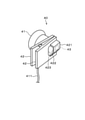
非常停止スイッチ40は、図2~図4にも示すように、スイッチ本体部41と、取付部42と、識別コード部43と、を備えている。スイッチ本体部41は、図1にも示すように、接続線411によってロボットコントローラ20に有線接続されている。本実施形態の場合、ロボットコントローラ20は、図1に示すようにコネクタ201を備えている。そして、スイッチ本体部41の接続線411は、コネクタ201を介してロボットコントローラ20に着脱可能に取り付けられている。
[Emergency stop switch configuration]
Next, the configuration of the
As shown in FIGS. 2 to 4, the
なお、コネクタ201は、スイッチ本体部41側に設けられていても良い。また、スイッチ本体部41は、必ずしもロボットコントローラ20に着脱可能に構成されている必要はない。例えば接続線411は、スイッチ本体部41及びロボットコントローラ20に取り外し不可能に構成されていても良い。
The
スイッチ本体部41は、例えば押しボタン式のスイッチであり、ユーザの押圧操作を受けてロボットコントローラ20の制御を非常停止状態に切り替える機能を有する。本実施形態の場合、スイッチ本体部41は、図1に示すようにNC接点であり、常時は回路を閉じており、操作時つまり押圧操作を受けた際には回路を開く構成である。
The switch
ロボットコントローラ20は、スイッチ本体部41に対して安全状態を示す信号を常時出力し、その信号が戻って来ている場合には、非常停止スイッチ40が操作されておらず安全な状態であると判断する。そして、ロボットコントローラ20は、非常停止スイッチ40が操作されておらず安全な状態であると判断しているときには、ロボット10に対する駆動制御を行うことができる。一方、スイッチ本体部41に対して出力した安全状態を示す信号を出力が戻って来ない場合、ロボットコントローラ20は、非常停止スイッチ40が操作されて回路が遮断されたと判断する。そして、ロボットコントローラ20は、ロボット10に対する制御を非常停止状態に切り替えて、ロボット10を非常停止させるとともにロボット10の駆動を禁止する。
The
取付部42は、図3及び図4に示すように、携帯端末30に対してスイッチ本体部41を着脱可能に取り付ける機能を有している。本実施形態の場合、取付部42は、2枚の板状の部材を含んでおり、携帯端末30を両側面から挟持可能なクリップ形状に構成されている。また、取付部42は、突出部421を一体に有している。突出部421は、図3及び図4に示すように、取付部42を携帯端末30に取り付けた場合に、携帯端末30のレンズ311に対向する位置に設けられており、レンズ311から離間する方向へ例えば台形状に突出している。そして、突出部421は、取付部42を携帯端末30に取り付けた場合に、レンズ311を覆うように構成されている。
As shown in FIGS. 3 and 4, the mounting
この場合、突出部421のうちレンズ311と対向する部分は平坦面となっている。そして、突出部421の突出量つまりレンズ311から突出部421の平坦面までの距離は、レンズ311の焦点距離以上に設定されている。また、突出部421の一部には、突出部421の内部と外部とを連通する開口部422が形成されている。この開口部422は、取付部42の外部の光を突出部421の内側へ導入可能な採光部422として機能する。すなわち、取付部42の外部の光は、採光部422を通って取付部42の内部に導かれる。これにより、取付部42内には、レンズ311を通して撮影するための十分な量の外光が導入される。
In this case, the portion of the protruding
本実施形態の場合、採光部422は、取付部42のうちレンズ311側の部材に設けられている。また、採光部422は、レンズ311の周囲にあって、レンズ311の撮影可能な範囲つまりレンズ311の視野の外側に位置している。そのため、採光部422は、光源からの光が直接レンズ311に当り難い構成となっている。なお、採光部422は、開口に限られず、例えば透明の樹脂やガラス等で構成しても良い。また、突出部421全体を透明の部材にすることで、突出部421全体を採光部としても良い。
In the case of the present embodiment, the
また、取付部42は、露出部423を有している。露出部423は、非常停止スイッチ40を携帯端末30に装着した場合においてレンズ311と重なる位置に設けられており、取付部42のうちレンズ311側の一部を切り欠いて又は切り抜いて形成されている。非常停止スイッチ40を携帯端末30に装着した場合、レンズ311は、図3に示すように、露出部423から外部に露出する。これにより、カメラ31は、取付部42に邪魔されることなく、突出部421の内側に設けられた識別コード部43を撮影することができる。
Further, the mounting
識別コード部43は、スイッチ本体部41を識別するための識別コードを、カメラ31で撮影可能な態様、つまりカメラ31の撮影によって携帯端末30で認識可能なように表示したものである。識別コード部43は、例えばバーコード等の1次元コードや、QRコード(登録商標)のような2次元コード等であり、例えばシールを貼付したり直接印刷したりして取付部42に表示されている。
The
識別コード部43は、図4にも示すように、スイッチ本体部41のうち突出部421の内側面つまりレンズ311と対向する平坦面部分に設けられている。つまり、識別コード部43は、取付部42を携帯端末30に取り付けた場合に携帯端末30のレンズ311に対向する位置に設けられている。識別コード部43に含まれる識別コードは、例えば文字、数字、及び記号等に変換して表現可能なものであり、スイッチ本体部41に固有つまり非常停止スイッチ40に固有のものである。
As shown in FIG. 4, the
なお、本実施形態において固有とは、必ずしも生産された非常停止スイッチの全てにわたって固有である必要はなく、例えば同じ作業現場で同時に複数の非常停止スイッチ40を使用する場合において各非常停止スイッチ40間で固有であれば良い。すなわち、本実施形態において固有とは、例えばある作業現場で複数の非常停止スイッチ40が使用される場合において、各非常停止スイッチ40の識別コードが重複してなければ良い。 In this embodiment, the term "unique" does not necessarily mean that the emergency stop switches are unique to all of the produced emergency stop switches. For example, when a plurality of emergency stop switches 40 are used at the same work site at the same time, between the emergency stop switches 40. It should be unique. That is, what is unique in this embodiment is that, for example, when a plurality of emergency stop switches 40 are used at a certain work site, the identification codes of the emergency stop switches 40 may not be duplicated.
[ロボットシステムの詳細]
次に、ロボットシステム1について更に詳細に説明する。
図1に示すように、ロボットシステム1を構成する携帯端末30は、レンズ311及び撮像部312を有するカメラ31の他、入力表示部32、読取処理部33、送信処理部34、及び端末制御部35を有している。入力表示部32は、例えば液晶型のタッチパネルディスプレイなどであって、ユーザの入力操作を検出するとともに、ユーザに対して各種情報を表示する。入力表示部32は、板状の携帯端末30の一方側の面、又は両側の面に設けられている。
[Details of robot system]
Next, the
As shown in FIG. 1, the
読取処理部33は、携帯端末30に非常停止スイッチ40が装着された場合に、非常停止スイッチ40が備える識別コード部43をカメラ31で撮像してその撮像した画像から識別コード部43に含まれる識別コードを読み取る機能を有する。送信処理部34は、読取処理部33で読み取った識別コードを、携帯端末30に内蔵する通信機器を用いてロボットコントローラ20に無線通信により送信する機能を有する。
When the
カメラ31による撮影、読取処理部33による読み取り処理、及び送信処理部34による送信処理は、一定周期で繰り返して実行される。このとき、カメラ31の撮像画像に識別コード部43が含まれていなければ、読取処理部33による識別コードの読み取りは失敗となる。この場合、送信処理部34は、読み取りに失敗した旨の情報又は空の情報をロボットコントローラ20に送信する。
The shooting by the
端末制御部35は、携帯端末30全体の制御を司っている。端末制御部35は、例えば図示しないCPUや、ROM、RAM、及び書き換え可能なフラッシュメモリ等の記憶領域を有するマイクロコンピュータを主体に構成されている。カメラ31及び入力表示部32は、端末制御部35に接続されており、端末制御部35によって制御される。
The
また、端末制御部35の図示しない記憶領域は、汎用品である携帯端末30をロボットシステム1に適用させるためのロボットシステム用のプログラムを記憶している。そして、端末制御部35は、図示しないCPUにおいてロボットシステム用のプログラムを実行することにより、読取処理部33及び送信処理部34をソフトウェアによって仮想的に実現する。
Further, a storage area (not shown) of the
ロボットコントローラ20は、駆動回路部21、停止判断処理部22、第1取得処理部23、第2取得処理部24、許可判断処理部25、及びシステム制御部26を有している。駆動回路部21は、携帯端末30からの操作に基づき、又は予め記憶しているプログラムに基づき、ロボット10の駆動を制御する機能を有する。
The
停止判断処理部22は、スイッチ本体部41に対して安全状態を示す信号を出力するとともに、スイッチ本体部41から戻ってくる信号を監視する。そして、停止判断処理部22は、スイッチ本体部41から戻ってくる信号の有無によって、非常停止スイッチ40の操作状態を判断し、ロボットコントローラ20の制御状態を切り替える。すなわち、停止判断処理部22は、スイッチ本体部41から信号が戻って来ている場合には、非常停止スイッチ40が操作されておらず安全な状態であると判断する。一方、停止判断処理部22は、スイッチ本体部41から信号が戻って来ない場合には、非常停止スイッチ40が操作されて回路が遮断されたと判断する。そして、非常停止スイッチ40が操作された場合、停止判断処理部22は、ロボット10に対する制御を非常停止状態に切り替えてロボット10の非常停止させる。
The stop
第1取得処理部23は、ロボットコントローラ20に有線接続された非常停止スイッチ40の識別コードを、カメラ31で識別コード部43を撮影する方法とは異なる方法で取得する機能を有する。カメラ31で識別コード部43を撮影する方法とは異なる方法で取得するとは、例えば次のような例がある。
The first
すなわち、例えば非常停止スイッチ40及び接続線411がロボットコントローラ20に着脱不可に構成されている場合、ロボットコントローラ20は、ロボットコントローラ20に内蔵する図示しない記憶領域に、当該ロボットコントローラ20に接続されている非常停止スイッチ40の識別コードを予め登録しておく。そして、第1取得処理部23は、その登録されている識別コードを取得することで、当該ロボットコントローラ20に接続されている非常停止スイッチ40の識別コードを取得する。
That is, for example, when the
また、例えば非常停止スイッチ40及び接続線411がロボットコントローラ20に着脱可能に構成されている場合、ユーザは、ロボットコントローラ20に直接又は間接的に接続された入力装置を用いて、ロボットコントローラ20に内蔵する図示しない記憶領域に、当該ロボットコントローラ20に接続される又は接続されている非常停止スイッチ40の識別コードを登録する。この場合、入力装置としては、例えば携帯端末30や、ロボットコントローラ20に接続されたコードリーダ、又はロボットコントローラ20に接続されたキーボードやマウスなどのユーザインタフェースデバイスなどが考えられる。そして、第1取得処理部23は、登録された識別コードを取得することで、当該ロボットコントローラ20に接続される又は接続されている非常停止スイッチ40の識別コードを取得する。
Further, for example, when the
第2取得処理部24は、携帯端末30の送信処理部34から送信された識別コードを取得する。すなわち、第2取得処理部24は、非常停止スイッチ40が携帯端末30に正常に装着されて、その携帯端末30のカメラ31が識別コード部43の識別コードを正常に実際に読み取れた場合に、その識別コードを取得することができる。換言すれば、第1取得処理部23は、非常停止スイッチ40が携帯端末30に装着されているか否かに関わらず、ロボットコントローラ20に接続されている非常停止スイッチ40の識別コードを取得する。一方、第2取得処理部24は、携帯端末30に実際に装着された非常停止スイッチ40の識別コードを取得する。
The second
許可判断処理部25は、第1取得処理部23で取得した識別コードと第2取得処理部24で取得した識別コードとが一致しない場合、ロボットコントローラ20に接続されている非常停止スイッチ40と、携帯端末30に装着されている非常停止スイッチ40とが同一のものでないと判断する。また、許可判断処理部25は、第1取得処理部23で識別コードが取得されなかった場合、ロボットコントローラ20に非常停止スイッチ40が接続されていないと判断する。また、許可判断処理部25は、第2取得処理部24で識別コードが取得されなかった場合、携帯端末30に非常停止スイッチ40が装着されていないと判断する。そして、これらの場合、許可判断処理部25は、携帯端末30に非常停止の機能が備わっていないと判断し、携帯端末30からの操作に基づくロボット10の操作を許可しない。つまり、この場合、ユーザは、携帯端末30を操作してロボット10を動作させることができない。
When the identification code acquired by the first
一方、許可判断処理部25は、第1取得処理部23で取得した識別コードと第2取得処理部24で取得した識別コードとが一致した場合には、携帯端末30からの操作に基づくロボット10の駆動を許可する。すなわち、第1取得処理部23で取得した識別コードと第2取得処理部24で取得した識別コードとが一致したということは、ロボットコントローラ20に接続されている非常停止スイッチ40と、携帯端末30に装着されている非常停止スイッチ40とが同一のものであること、つまり、ロボットコントローラ20に接続されている非常停止スイッチ40が装着されるべき携帯端末30に実際に装着されていることを意味する。したがって、この場合、許可判断処理部25は、携帯端末30に非常停止の機能が備ったと判断し、その携帯端末30からの操作に基づくロボット10の操作を許可する。これにより、ユーザは、携帯端末30を操作することでロボット10を動作させることができる。
On the other hand, when the identification code acquired by the first
システム制御部26は、ロボットコントローラ20全体の制御を司っている。システム制御部26は、例えば図示しないCPUや、ROM、RAM、及び書き換え可能なフラッシュメモリ等の記憶領域を有するマイクロコンピュータを主体に構成されている。駆動回路部21、停止判断処理部22、第1取得処理部23、第2取得処理部24、及び許可判断処理部25は、システム制御部26に接続されており、システム制御部26によって制御される。
The
また、システム制御部26の図示しない記憶領域は、ロボットコントローラ20をロボットシステム1に適用させるためのロボットシステム用のプログラムを記憶している。そして、システム制御部26は、図示しないCPUにおいてロボットシステム用のプログラムを実行することにより、停止判断処理部22、第1取得処理部23、第2取得処理部24、及び許可判断処理部25をソフトウェアによって仮想的に実現する。なお、これら停止判断処理部22、第1取得処理部23、第2取得処理部24、及び許可判断処理部25は、例えばシステム制御部26と一体の集積回路としてハードウェア的に実現してもよい。
Further, a storage area (not shown) of the
[ロボットシステムの制御フロー]
次に、図5及び図6も参照して、ロボットコントローラ20及び携帯端末30で実行される制御内容について説明する。
まず、携帯端末30の端末制御部35で実行される制御内容について、図5を参照して説明する。端末制御部35は、ロボットシステム用のプログラムを実行すると(図5のスタート)、まず、ステップS11の処理を実行する。端末制御部35は、ステップS11において、カメラ31及び読取処理部33の処理によって、携帯端末30に装着された非常停止スイッチ40が備える識別コード部43の検出及び読み取りを行う。
[Robot system control flow]
Next, the control contents executed by the
First, the control content executed by the
次に、端末制御部35は、ステップS12において、識別コードの読み取りが有ったか否かを判断する。端末制御部35は、識別コードの読み取りが有った場合(ステップS12でYES)、ステップS13へ処理を移行させ、送信処理部34の処理によってステップS11で読み取った識別コードをロボットコントローラ20へ送信する。その後、端末制御部35は、ステップS11へ処理を戻し、上記処理を再度実行する。
Next, the
一方、端末制御部35は、識別コードの読み取りが無かった場合(ステップS12でNO)、携帯端末30には非常停止スイッチ40が正常に装着されていないと判断し、ステップS14へ処理を移行させる。そして、端末制御部35は、ステップS14において、携帯端末30に非常停止スイッチ40が正しく装着されていない旨の警告情報を例えば入力表示部32に表示する。これにより、ユーザに対して警告情報を報知する。その後、端末制御部35は、ステップS11へ処理を戻し、上記処理を再度実行する。この場合、端末制御部35は、上記処理内容を所定のサイクルで繰り返す。
On the other hand, if the identification code is not read (NO in step S12), the
次に、ロボットコントローラ20のシステム制御部26で実行される制御内容について、図6を参照して説明する。システム制御部26は、ロボットシステム用のプログラムを実行すると(図6のスタート)、まずステップS21において、第1取得処理部23の処理によってロボットコントローラ20に接続されている非常停止スイッチ40の識別コードを取得する。
Next, the control contents executed by the
次に、システム制御部26は、ステップS22において、第2取得処理部24で識別コードの取得が有ったか否かを判定する。システム制御部26は、第2取得処理部24で識別コードの取得が無かった場合、つまり携帯端末30から識別コードを受信できなかった場合(ステップS22でNO)、携帯端末30に非常停止スイッチ40が正常に装着されていないと判断する。そして、システム制御部26は、ステップS23へ処理を移行させて、携帯端末30の操作に基づくロボット10の動作を禁止する。そして、システム制御部26は、ステップS22へ処理を戻す。
Next, in step S22, the
一方、システム制御部26は、第2取得処理部24で識別コードの取得が有った場合、つまり携帯端末30から識別コードを受信できた場合(ステップS22でYES)、携帯端末30に非常停止スイッチ40が装着されていると判断し、ステップS24へ処理を移行させる。次に、システム制御部26は、許可判断処理部25の処理によって、第1取得処理部23で取得した識別コードと第2取得処理部24で取得した識別コードとが一致しているか否かを判定する。
On the other hand, when the second
システム制御部26は、第1取得処理部23で取得した識別コードと第2取得処理部24で取得した識別コードとが一致しない場合(ステップS24でNO)、ロボットコントローラ20に接続された非常停止スイッチ40と携帯端末30に装着された非常停止スイッチ40とが同一のものでないと判断する。そして、システム制御部26は、ステップS23へ処理を移行させて、携帯端末30の操作に基づくロボット10の動作を禁止する。そして、システム制御部26は、ステップS22へ処理を戻す。
When the identification code acquired by the first
なお、この場合、システム制御部26は、携帯端末30に対して、ロボットコントローラ20に接続された非常停止スイッチ40と携帯端末30に装着された非常停止スイッチ40とが同一のものでない旨の警告情報を送信し、その警告情報を携帯端末30の入力表示部32に表示させるようにしても良い。
In this case, the
また、システム制御部26は、第1取得処理部23で取得した識別コードと第2取得処理部24で取得した識別コードとが一致した場合(ステップS24でYES)、ロボットコントローラ20に接続された非常停止スイッチ40と携帯端末30に装着された非常停止スイッチ40とが同一のものであると判断する。つまり、この場合、システム制御部26は、ロボットコントローラ20に接続された非常停止スイッチ40が、携帯端末30に正しく装着されていると判断する。そして、システム制御部26は、ステップS25へ処理を移行させて、携帯端末30の操作に基づくロボット10の動作を許可する。これにより、ユーザは、携帯端末30を操作してロボット10の教示操作を行うことができる。そして、システム制御部26は、ステップS22へ処理を戻し、所定のサイクルで上記制御を繰り返す。
Further, the
以上説明した実施形態によれば、非常停止スイッチ40は、スイッチ本体部41と、取付部42と、識別コード部43と、を備える。スイッチ本体部41は、ロボット10の駆動を制御するロボットコントローラ20に有線接続されユーザの操作を受けてロボットコントローラ20の制御を非常停止状態に切り替える。取付部42は、ユーザの操作を受け付ける携帯端末30に対してスイッチ本体部41を着脱可能に取り付ける。識別コード部43は、取付部42を携帯端末30に取り付けた場合に携帯端末30が備えるカメラ31のレンズ311に対向する位置に設けられ、スイッチ本体部41を識別する識別コードをカメラ31で撮影可能な態様で表示する。
According to the embodiment described above, the
これによれば、ユーザは、取付部42によって、非常停止スイッチ40のスイッチ本体部41をスマートフォンやタブレット端末等の携帯端末30に着脱可能に容易に取り付けることができる。そして、取付部42を携帯端末30に取り付けた場合、携帯端末30が備えるカメラ31のレンズ311に対向する位置には、識別コード部43が位置する。すなわち、カメラ31で撮影した画像内に識別コード部43が含まれていないということは、非常停止スイッチ40が携帯端末30に正しく装着されていないことを意味する。
According to this, the user can easily attach / detach the switch
一方、カメラ31で撮影した画像内に識別コード部43が含まれているということは、非常停止スイッチ40が携帯端末30に正しく装着されていることを意味する。そのため、携帯端末30又はロボットコントローラ20は、例えばカメラ31の撮影を一定間隔で実行し、その撮影した画像内に識別コード部43が含まれているか否かによって、非常停止スイッチ40が携帯端末30に装着されているか否かを判断することができる。このように、本発明によれば、スマートフォンやタブレット装置等の携帯端末30をロボット10の操作装置として使用する場合に、その携帯端末30に確実に非常停止スイッチ40を確実に装着されているようにすることができる。
On the other hand, the fact that the
また、非常停止スイッチ40において、取付部42は、取付部42を携帯端末30に取り付けた場合にレンズ311から離間する方向へ突出した突出部421を有している。そして、識別コード部43は、突出部421の内側に面に設けられている。
Further, in the
これによれば、識別コード部43が突出部421の内側の面つまりカメラ31のレンズ311と対向する側の面に設けられていることから、非常停止スイッチ40を携帯端末30に取り付けた場合において、カメラ31のレンズ311から識別コード部43までの距離を確保し、その距離を一定に維持することができる。これにより、例えば識別コード部43がカメラ31のレンズ311の焦点距離よりも接近し過ぎることを防ぎ、携帯端末30のカメラ31による識別コード部43の撮影の精度を向上させることができる。
According to this, since the
また、非常停止スイッチ40は、外部の光を識別コード部43へ導入可能な採光部422を更に備える。これによれば、採光部422から識別コード部43へ外光が導入されることによって、カメラ31の撮影に必要な光を確保することができる。そのため、これによればフラッシュやライト等の光源が無くても撮影に必要な光量を確保し易くなり、その結果、識別コード部43の撮影の精度、つまり識別コード部43に含まれる識別コードの認識精度を向上させることができる。
Further, the
ここで、例えばスマートフォンなどの携帯端末は、フラッシュ用の光源を備えているものもある。しかしながら、このような光源は、一般的にレンズ311の近傍に設けられていることが多い。そのため、このようなフラッシュ用の光源を用いて識別コード部43を撮影すると、光源から識別コード部43までの距離が近すぎるため、光源からの光が強すぎていわゆる白飛びが生じ、その結果、識別コードの誤認識が生じて認識精度が低下してしまう可能性が高まる。そのため、本実施形態のように、カメラ31によって識別コード部43を接写する場合には、フラッシュ等の光源を用いずに撮影する方が有利である。
Here, for example, some mobile terminals such as smartphones are provided with a light source for a flash. However, such a light source is generally provided in the vicinity of the
これに対し、本実施形態によれば、非常停止スイッチ40は、識別コード部43へ外光を導入するための採光部422を備えていることにより、カメラ31の撮影に必要な光を確保することができる。これによれば、カメラ31は、フラッシュ等の光源を用いずに撮影することができるため、いわゆる白飛びが生じ難く、その結果、識別コード部43に含まれる識別コードの認識精度を向上させることができる。
On the other hand, according to the present embodiment, the
また、例えば作業者が作業空間内に設置された照明等を付けずに暗所で操作しようとした場合、作業者は、操作対象となるロボット10の動作をはっきりと見ることができなくなるため、その操作には危険が伴う。これに対し、本実施形態によれば、作業空間が暗い場合には、採光部422から導入される光量が少なくなり、カメラ31による識別コード部43の撮影が適切に行われなくなる。つまり、本実施形態によれば、カメラ31により識別コード部43の撮影を適切に行うことができないような暗い環境下においてまでも、携帯端末30がロボット10の操作装置として機能してしまうことを防ぐことができ、その結果、安全性の向上が図られる。
Further, for example, when a worker tries to operate in a dark place without lighting or the like installed in the work space, the worker cannot clearly see the operation of the
なお、カメラ31は、必要に応じて携帯端末30が備えるフラッシュ等の光源を用いて撮影しても良い。この場合、携帯端末30が備えるフラッシュ等の光源が輝度や発光時間を調整できるものであれば、携帯端末30は、その光源の輝度や発光時間等を調整して白飛びが生じないようにしても良い。
If necessary, the
本実施形態のロボットシステム1は、ロボット10の駆動を制御するロボットコントローラ20と、カメラ31を有しロボットコントローラ20と無線通信可能な携帯端末30と、非常停止スイッチ40と、を備える。非常停止スイッチ40は、スイッチ本体部41と、取付部42と、識別コード部43と、を有する。スイッチ本体部41は、ロボットコントローラ20に有線接続されユーザの操作を受けてロボットコントローラ20の制御を非常停止状態に切り替える。取付部42は、携帯端末30に対してスイッチ本体部41を着脱可能に取り付ける。識別コード部43は、カメラ31のレンズ311に対向する位置に設けられスイッチ本体部41を識別する識別コードをカメラ31で撮影可能な態様で表示する。
The
携帯端末30は、読取処理部33と、送信処理部34と、を有する。読取処理部33は、携帯端末30に非常停止スイッチ40が装着された場合に非常停止スイッチ40が備える識別コード部43をカメラ31で撮影してその撮影した画像から識別コード部43に含まれる識別コードを読み取る処理を行う。送信処理部34は、読取処理部33で読み取った識別コードをロボットコントローラ20に送信する処理を行う。
The
そして、ロボットコントローラ20は、第1取得処理部23と、第2取得処理部24と、許可判断処理部25と、を有する。第1取得処理部23は、ロボットコントローラ20に有線接続された非常停止スイッチ40の識別コードをカメラ31で識別コード部43を撮影する方法とは異なる方法で取得する処理を行う。第2取得処理部24は、携帯端末30の送信処理部34から送信された識別コードを取得する処理を行う。許可判断処理部25は、第1取得処理部23で取得した識別コードと第2取得処理部24で取得した識別コードとが一致した場合に携帯端末30からの操作に基づくロボット10の駆動を許可する処理を行う。
The
これによれば、上述した非常停止スイッチ40を、スマートフォンやタブレット端末等の携帯端末30に容易に適用させることができる。すなわち、携帯端末30に非常停止スイッチ40を装着して操作装置として用いる場合、ロボットコントローラ20に実際に有線接続された非常停止スイッチ40と、携帯端末30に実際に装着された非常停止スイッチ40とが同一のものであることを確認する必要がある。
According to this, the above-mentioned
例えばあるロボットコントローラ20に有線接続された非常停止スイッチ40が、そのロボットコントローラ20に対応した携帯端末30とは異なる携帯端末に誤って装着されてしまった場合、ユーザは、非常停止スイッチ40を操作しても、目的とするロボット10を非常停止させることができない。つまりこの場合、ユーザは、実質的に非常停止機能を有さない携帯端末30を、操作装置として使用することになるため、安全性に問題が生じる。そのため、携帯端末30に非常停止スイッチ40を装着して操作装置として用いる場合、ロボットコントローラ20と、携帯端末30と、非常停止スイッチ40とを相互に紐付けする必要がある。
For example, if the
これに対し、本構成によれば、ロボットコントローラ20において、第1取得処理部23は、ロボットコントローラ20に有線接続された又は有線接続される非常停止スイッチ40の識別コードを取得する。これにより、ロボットコントローラ20は、第1取得処理部23で取得した識別コードにより、ロボットコントローラ20と非常停止スイッチ40との紐付けを行うことができる。また、第2取得処理部24は、携帯端末30に実際に装着された非常停止スイッチ40の識別コードを取得する。これにより、ロボットコントローラ20は、第2取得処理部24で取得した識別コードにより、携帯端末30と非常停止スイッチ40との紐付けを行うことができる。
On the other hand, according to the present configuration, in the
そして、許可判断処理部25は、第1取得処理部23で取得した識別コードと第2取得処理部24で取得した識別コードとが一致した場合、つまりロボットコントローラ20に有線接続された非常停止スイッチ40と、携帯端末30に装着された非常停止スイッチ40とが同一のものであると確認された場合に、携帯端末30からの操作に基づくロボット10の駆動を許可する。
Then, the permission
つまり、例えばあるロボットコントローラ20に有線接続された非常停止スイッチ40が、そのロボットコントローラ20に対応した携帯端末30とは異なる携帯端末に誤って装着されてしまった場合には、携帯端末30からの操作に基づくロボット10の駆動を許可されない。このため、携帯端末30に非常停止スイッチ40が装着されていなかったり、誤って他のロボットに対応した非常停止スイッチを装着してしまったりして、携帯端末30が実質的に非常停止機能を有していない場合には、その携帯端末30を操作装置として使用することができないため、安全性を確保することができる。
That is, for example, when the
(第2実施形態)
次に、第2実施形態について図7を参照して説明する。第2実施形態では、第1取得処理部23による非常停止スイッチ40の識別コードの取得方法が、上記第1実施形態と異なる。
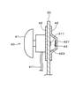
本実施形態の非常停止スイッチ40は、図7に示すように、上記第1実施形態の非常停止スイッチ40の構成に加えて、コネクタ401及び識別コード記憶部44を備えている。コネクタ401は、上記第1実施形態のコネクタ201に代替するものであり、例えば非常停止スイッチ40のスイッチ本体部41に設けられている。コネクタ201は、ロボットコントローラ20から延び出た接続線411を着脱可能に接続する。識別コード記憶部44は、非常停止スイッチ40のスイッチ本体部41の識別コードを記憶する。
(Second Embodiment)
Next, the second embodiment will be described with reference to FIG. 7. In the second embodiment, the method of acquiring the identification code of the
As shown in FIG. 7, the
そして、コネクタ401及び接続線411を介して非常停止スイッチ40がロボットコントローラ20に有線接続されると、第1取得処理部23は、識別コード記憶部44にアクセスして、識別コード記憶部44に記憶されている非常停止スイッチ40の識別コードを自動で取得する。つまり、識別コード記憶部44に記憶されている識別コードは、非常停止スイッチ40がロボットコントローラ20に有線接続された場合にロボットコントローラ20に自動で送信される。
Then, when the
ここで、例えば一つの作業現場に複数台のロボット10が存在する場合、ユーザは、各ロボット10に対応させて複数の非常停止スイッチ40を準備することが考えられる。この場合、各ロボットコントローラ20は、それぞれ自己に実際に有線接続された非常停止スイッチ40の識別コードを予め登録しておくことで、他のロボットコントローラに接続された非常停止スイッチとの混同を防止することができる。この場合、ロボットコントローラ20に対する識別コードの登録は、例えばユーザが例えば携帯端末30や、ロボットコントローラ20に接続されたユーザインタフェースデバイス等を用いて手作業で行うことが考えられるが、この作業を手作業で行うのは煩雑である。
Here, for example, when a plurality of
一方、本実施形態によれば、非常停止スイッチ40の識別コードは、ユーザが非常停止スイッチ40をロボットコントローラ20に接続するだけで、その非常停止スイッチ40の識別コードが自動でロボットコントローラ20に登録される。そのため、ユーザは、非常停止スイッチ40の識別コードの登録作業が不要となり、その結果、利便性の向上を図ることができる。
On the other hand, according to the present embodiment, the identification code of the
また、本実施形態によれば、非常停止スイッチ40と、ロボット10及びロボットコントローラ20との対応関係を、予め設定しておく必要がない。つまり、ユーザは、非常停止スイッチ40を、あるロボットコントローラから他のロボットコントローラ20に接続し直すことで、その非常停止スイッチ40を新たに接続したロボットコントローラ20に紐付けすることができる。したがって、これによれば、1つの非常停止スイッチ40を複数のロボット10及びロボットコントローラ20に対応させることができるため、非常停止スイッチ40の流用性が増して、利便性の向上が図られる。
Further, according to the present embodiment, it is not necessary to set in advance the correspondence relationship between the
なお、上記説明した各実施形態は、上記し且つ図面に記載した各実施形態に限定されるものではなく、発明の要旨を逸脱しない範囲において適宜変更することができる。 The embodiments described above are not limited to the embodiments described above and shown in the drawings, and can be appropriately modified without departing from the gist of the invention.
図面中、1はロボットシステム、10はロボット、20はロボットコントローラ、23は第1取得処理部、24は第2取得処理部、25は許可判断処理部、30は携帯端末、33は読取処理部、34は送信処理部、40は非常停止スイッチ、41はスイッチ本体部、42は取付部、421は突出部、422は開口部(採光部)、43は識別コード部、44は識別コード記憶部、を示す。 In the drawing, 1 is a robot system, 10 is a robot, 20 is a robot controller, 23 is a first acquisition processing unit, 24 is a second acquisition processing unit, 25 is a permission judgment processing unit, 30 is a mobile terminal, and 33 is a reading processing unit. 34 is a transmission processing unit, 40 is an emergency stop switch, 41 is a switch body unit, 42 is a mounting unit, 421 is a protruding portion, 422 is an opening (lighting unit), 43 is an identification code unit, and 44 is an identification code storage unit. , Is shown.
Claims (6)
ユーザの操作を受け付ける携帯端末に対して前記スイッチ本体部を着脱可能に取り付ける取付部と、
前記取付部を前記携帯端末に取り付けた場合に前記携帯端末が備えるカメラのレンズに対向する位置に設けられ、前記スイッチ本体部を識別する識別コードを前記カメラで撮影可能な態様で表示する識別コード部と、
を備える非常停止スイッチ。 A switch body that is connected to a robot controller that controls the drive of the robot by wire and switches the control of the robot controller to the emergency stop state in response to a user's operation.
A mounting part that detachably attaches the switch body to a mobile terminal that accepts user operations,
An identification code provided at a position facing the lens of the camera included in the mobile terminal when the mounting portion is attached to the mobile terminal, and displaying an identification code for identifying the switch main body in a manner capable of being photographed by the camera. Department and
Equipped with an emergency stop switch.
前記識別コード部は、前記突出部の内側に面に設けられている、
請求項1に記載の非常停止スイッチ。 The mounting portion has a protruding portion that protrudes in a direction away from the lens when the mounting portion is mounted on the mobile terminal.
The identification code portion is provided on a surface inside the protrusion.
The emergency stop switch according to claim 1.
請求項1又は2に記載の非常停止スイッチ。 Further provided with a daylighting unit capable of introducing external light into the identification code unit.
The emergency stop switch according to claim 1 or 2.
請求項1から3のいずれか一項に記載の非常停止スイッチ。 An identification code storage unit for storing the identification code is further provided, and the identification code stored in the identification code storage unit is automatically transmitted to the robot controller when connected to the robot controller by wire.
The emergency stop switch according to any one of claims 1 to 3.
カメラを有し前記ロボットコントローラと無線通信可能な携帯端末と、
前記ロボットコントローラに有線接続されユーザの操作を受けて前記ロボットコントローラの制御を非常停止状態に切り替えるスイッチ本体部と、前記携帯端末に対して前記スイッチ本体部を着脱可能に取り付ける取付部と、前記カメラのレンズに対向する位置に設けられ前記スイッチ本体部を識別する識別コードを前記カメラで撮影可能な態様で表示する識別コード部と、を有する非常停止スイッチと、を備え、
前記携帯端末は、
当該携帯端末に前記非常停止スイッチが装着された場合に前記非常停止スイッチが備える前記識別コード部を前記カメラで撮影してその撮影した画像から前記識別コード部に含まれる識別コードを読み取る読取処理部と、
前記読取処理部で読み取った前記識別コードを前記ロボットコントローラに送信する送信処理部と、を有し、
前記ロボットコントローラは、
前記ロボットコントローラに有線接続された前記非常停止スイッチの前記識別コードを前記カメラで前記識別コード部を撮影する方法とは異なる方法で取得する第1取得処理部と、
前記携帯端末の前記送信処理部から送信された前記識別コードを取得する第2取得処理部と、
前記第1取得処理部で取得した識別コードと前記第2取得処理部で取得した識別コードとが一致した場合に前記携帯端末からの操作に基づく前記ロボットの駆動を許可する許可判断処理部と、を有する、
ロボットシステム。 A robot controller that controls the drive of the robot and
A mobile terminal that has a camera and is capable of wireless communication with the robot controller,
A switch main body that is connected to the robot controller by wire and switches the control of the robot controller to an emergency stop state in response to a user's operation, a mounting portion that detachably attaches the switch main body to the mobile terminal, and the camera. An emergency stop switch having an identification code unit provided at a position facing the lens of the switch body and displaying an identification code for identifying the switch body unit in a manner capable of being photographed by the camera.
The mobile terminal is
When the emergency stop switch is attached to the mobile terminal, a reading processing unit that captures the identification code unit included in the emergency stop switch with the camera and reads the identification code included in the identification code unit from the captured image. When,
It has a transmission processing unit that transmits the identification code read by the reading processing unit to the robot controller.
The robot controller is
A first acquisition processing unit that acquires the identification code of the emergency stop switch wiredly connected to the robot controller by a method different from the method of photographing the identification code unit with the camera.
A second acquisition processing unit that acquires the identification code transmitted from the transmission processing unit of the mobile terminal, and a second acquisition processing unit.
A permission determination processing unit that permits driving of the robot based on an operation from the mobile terminal when the identification code acquired by the first acquisition processing unit and the identification code acquired by the second acquisition processing unit match. Have,
Robot system.
前記第1取得処理部は、前記非常停止スイッチが前記ロボットコントローラに有線接続された場合に前記識別コード記憶部に記憶されている前記識別コードを自動で取得する、
請求項5に記載のロボットシステム。 The emergency stop switch further has an identification code storage unit for storing the identification code.
The first acquisition processing unit automatically acquires the identification code stored in the identification code storage unit when the emergency stop switch is wiredly connected to the robot controller.
The robot system according to claim 5.
Priority Applications (2)
| Application Number | Priority Date | Filing Date | Title |
|---|---|---|---|
| JP2018176207A JP7006550B2 (en) | 2018-09-20 | 2018-09-20 | Emergency stop switch and robot system |
| JP2021208215A JP7367749B2 (en) | 2018-09-20 | 2021-12-22 | Emergency stop switch and robot system |
Applications Claiming Priority (1)
| Application Number | Priority Date | Filing Date | Title |
|---|---|---|---|
| JP2018176207A JP7006550B2 (en) | 2018-09-20 | 2018-09-20 | Emergency stop switch and robot system |
Related Child Applications (1)
| Application Number | Title | Priority Date | Filing Date |
|---|---|---|---|
| JP2021208215A Division JP7367749B2 (en) | 2018-09-20 | 2021-12-22 | Emergency stop switch and robot system |
Publications (2)
| Publication Number | Publication Date |
|---|---|
| JP2020044625A JP2020044625A (en) | 2020-03-26 |
| JP7006550B2 true JP7006550B2 (en) | 2022-01-24 |
Family
ID=69900511
Family Applications (2)
| Application Number | Title | Priority Date | Filing Date |
|---|---|---|---|
| JP2018176207A Active JP7006550B2 (en) | 2018-09-20 | 2018-09-20 | Emergency stop switch and robot system |
| JP2021208215A Active JP7367749B2 (en) | 2018-09-20 | 2021-12-22 | Emergency stop switch and robot system |
Family Applications After (1)
| Application Number | Title | Priority Date | Filing Date |
|---|---|---|---|
| JP2021208215A Active JP7367749B2 (en) | 2018-09-20 | 2021-12-22 | Emergency stop switch and robot system |
Country Status (1)
| Country | Link |
|---|---|
| JP (2) | JP7006550B2 (en) |
Families Citing this family (2)
| Publication number | Priority date | Publication date | Assignee | Title |
|---|---|---|---|---|
| KR102549292B1 (en) * | 2022-06-09 | 2023-06-30 | 임형순 | Repositionable Velcro Type Wireless Emergency Switch System |
| WO2024004163A1 (en) * | 2022-06-30 | 2024-01-04 | ファナック株式会社 | Mechanical manipulation system for executing authentication process, and computer program |
Citations (9)
| Publication number | Priority date | Publication date | Assignee | Title |
|---|---|---|---|---|
| JP2004355195A (en) | 2003-05-28 | 2004-12-16 | Yaskawa Electric Corp | Teaching operation device for robot |
| DE102010025781A1 (en) | 2010-07-01 | 2012-01-05 | Kuka Laboratories Gmbh | Portable safety input apparatus useful for robot controller, comprises input device to enter safety signal to robot controller, and an interface to communicate with hand-held unit detachably connected with apparatus for controlling robot |
| WO2014127822A1 (en) | 2013-02-21 | 2014-08-28 | Abb Technology Ltd | An industrial robot system comprising an enabling unit and a plurality of general purpose devices and a method for controlling the robot system |
| JP2015177304A (en) | 2014-03-14 | 2015-10-05 | オムロン株式会社 | Radio control terminal, radio control device for control object, and emergency stop control program |
| JP2017202550A (en) | 2016-05-11 | 2017-11-16 | 川崎重工業株式会社 | Robot teaching device |
| WO2017198580A1 (en) | 2016-05-20 | 2017-11-23 | Kuka Roboter Gmbh | Mobile security basic control device comprising a coding device for a mobile terminal with multi-touchscreen and method for setting up a uniquely assigned control link |
| JP2017213645A (en) | 2016-05-31 | 2017-12-07 | 株式会社アスコ | Teaching device |
| DE102016211244A1 (en) | 2016-06-23 | 2017-12-28 | Kuka Roboter Gmbh | Robotic handheld device network with a basic control position sensor |
| JP2018130803A (en) | 2017-02-16 | 2018-08-23 | ファナック株式会社 | Operation command system for robot, tablet terminal and control method of tablet terminal |
Family Cites Families (4)
| Publication number | Priority date | Publication date | Assignee | Title |
|---|---|---|---|---|
| JP3602587B2 (en) * | 1994-12-19 | 2004-12-15 | オリンパス株式会社 | Camera system and camera body |
| JP2007067576A (en) | 2005-08-29 | 2007-03-15 | Nec Corp | Mobile terminal, content server, control program for them, and content providing and advertising service system |
| JP6289837B2 (en) * | 2013-08-23 | 2018-03-07 | マクセルホールディングス株式会社 | Skin condition measurement analysis information management system and skin condition measurement analysis information management method |
| JP6348159B2 (en) * | 2016-10-24 | 2018-06-27 | ファナック株式会社 | Emergency stop system attached to portable equipment |
-
2018
- 2018-09-20 JP JP2018176207A patent/JP7006550B2/en active Active
-
2021
- 2021-12-22 JP JP2021208215A patent/JP7367749B2/en active Active
Patent Citations (9)
| Publication number | Priority date | Publication date | Assignee | Title |
|---|---|---|---|---|
| JP2004355195A (en) | 2003-05-28 | 2004-12-16 | Yaskawa Electric Corp | Teaching operation device for robot |
| DE102010025781A1 (en) | 2010-07-01 | 2012-01-05 | Kuka Laboratories Gmbh | Portable safety input apparatus useful for robot controller, comprises input device to enter safety signal to robot controller, and an interface to communicate with hand-held unit detachably connected with apparatus for controlling robot |
| WO2014127822A1 (en) | 2013-02-21 | 2014-08-28 | Abb Technology Ltd | An industrial robot system comprising an enabling unit and a plurality of general purpose devices and a method for controlling the robot system |
| JP2015177304A (en) | 2014-03-14 | 2015-10-05 | オムロン株式会社 | Radio control terminal, radio control device for control object, and emergency stop control program |
| JP2017202550A (en) | 2016-05-11 | 2017-11-16 | 川崎重工業株式会社 | Robot teaching device |
| WO2017198580A1 (en) | 2016-05-20 | 2017-11-23 | Kuka Roboter Gmbh | Mobile security basic control device comprising a coding device for a mobile terminal with multi-touchscreen and method for setting up a uniquely assigned control link |
| JP2017213645A (en) | 2016-05-31 | 2017-12-07 | 株式会社アスコ | Teaching device |
| DE102016211244A1 (en) | 2016-06-23 | 2017-12-28 | Kuka Roboter Gmbh | Robotic handheld device network with a basic control position sensor |
| JP2018130803A (en) | 2017-02-16 | 2018-08-23 | ファナック株式会社 | Operation command system for robot, tablet terminal and control method of tablet terminal |
Also Published As
| Publication number | Publication date |
|---|---|
| JP2022028062A (en) | 2022-02-14 |
| JP7367749B2 (en) | 2023-10-24 |
| JP2020044625A (en) | 2020-03-26 |
Similar Documents
| Publication | Publication Date | Title |
|---|---|---|
| JP7367749B2 (en) | Emergency stop switch and robot system | |
| CN106415413B (en) | Programmable display, portable terminal device, data processing method | |
| JP4822116B2 (en) | Vehicle and remote control device | |
| US10427201B2 (en) | Handheld pressing device | |
| US10379513B2 (en) | Monitoring system, monitoring device, and monitoring method | |
| KR101797246B1 (en) | Operating device and movement device with the same | |
| EP2924977A1 (en) | Lens module and portable photography device | |
| WO2015194658A1 (en) | Robot control system | |
| JP6558527B2 (en) | Electronic device, electronic device control method, program, and wireless communication system | |
| US11077560B2 (en) | Manipulator system and method for identifying operating devices | |
| JP2007003646A (en) | Camera system, lens unit and accessory | |
| US20190102519A1 (en) | Targeting adapter for mobile scanning device | |
| KR101779718B1 (en) | Safety cane apparatus for blind people and control method thereof | |
| EP3159119A1 (en) | Worker terminal for robot operation | |
| CN111614919B (en) | Image recording device and head-mounted display | |
| US20170140491A1 (en) | Operation advance indication apparatus | |
| WO2019023846A1 (en) | Data conversion and capture control method, system, cradle head assembly, and unmanned aerial vehicle system | |
| JP2017041417A (en) | Electronic apparatus, control method thereof, and program | |
| JP2022121739A (en) | Robot operation device | |
| KR20190129300A (en) | Smart watch with sensors and recognition method using the same | |
| KR20100034888A (en) | The bar code scanner with function of picture-taking | |
| CN110058675B (en) | Safety locking system | |
| JP6390135B2 (en) | Hot water system | |
| CA2994769C (en) | Control panel having nc function for machine tool | |
| JP6444024B2 (en) | Drive unit and system having the drive unit |
Legal Events
| Date | Code | Title | Description |
|---|---|---|---|
| A621 | Written request for application examination |
Free format text: JAPANESE INTERMEDIATE CODE: A621 Effective date: 20210209 |
|
| A977 | Report on retrieval |
Free format text: JAPANESE INTERMEDIATE CODE: A971007 Effective date: 20211115 |
|
| TRDD | Decision of grant or rejection written | ||
| A01 | Written decision to grant a patent or to grant a registration (utility model) |
Free format text: JAPANESE INTERMEDIATE CODE: A01 Effective date: 20211207 |
|
| A61 | First payment of annual fees (during grant procedure) |
Free format text: JAPANESE INTERMEDIATE CODE: A61 Effective date: 20211220 |
|
| R150 | Certificate of patent or registration of utility model |
Ref document number: 7006550 Country of ref document: JP Free format text: JAPANESE INTERMEDIATE CODE: R150 |