JP7004232B2 - Sheet feeder, image forming device and image forming system - Google Patents
Sheet feeder, image forming device and image forming system Download PDFInfo
- Publication number
- JP7004232B2 JP7004232B2 JP2017029639A JP2017029639A JP7004232B2 JP 7004232 B2 JP7004232 B2 JP 7004232B2 JP 2017029639 A JP2017029639 A JP 2017029639A JP 2017029639 A JP2017029639 A JP 2017029639A JP 7004232 B2 JP7004232 B2 JP 7004232B2
- Authority
- JP
- Japan
- Prior art keywords
- sheet
- suction
- feeding device
- air
- image forming
- Prior art date
- Legal status (The legal status is an assumption and is not a legal conclusion. Google has not performed a legal analysis and makes no representation as to the accuracy of the status listed.)
- Expired - Fee Related
Links
Images


Classifications
-
- B—PERFORMING OPERATIONS; TRANSPORTING
- B65—CONVEYING; PACKING; STORING; HANDLING THIN OR FILAMENTARY MATERIAL
- B65H—HANDLING THIN OR FILAMENTARY MATERIAL, e.g. SHEETS, WEBS, CABLES
- B65H3/00—Separating articles from piles
- B65H3/08—Separating articles from piles using pneumatic force
- B65H3/14—Air blasts producing partial vacuum
-
- B—PERFORMING OPERATIONS; TRANSPORTING
- B65—CONVEYING; PACKING; STORING; HANDLING THIN OR FILAMENTARY MATERIAL
- B65H—HANDLING THIN OR FILAMENTARY MATERIAL, e.g. SHEETS, WEBS, CABLES
- B65H3/00—Separating articles from piles
- B65H3/46—Supplementary devices or measures to assist separation or prevent double feed
- B65H3/48—Air blast acting on edges of, or under, articles
-
- B—PERFORMING OPERATIONS; TRANSPORTING
- B65—CONVEYING; PACKING; STORING; HANDLING THIN OR FILAMENTARY MATERIAL
- B65H—HANDLING THIN OR FILAMENTARY MATERIAL, e.g. SHEETS, WEBS, CABLES
- B65H3/00—Separating articles from piles
- B65H3/08—Separating articles from piles using pneumatic force
- B65H3/12—Suction bands, belts, or tables moving relatively to the pile
- B65H3/124—Suction bands or belts
-
- B—PERFORMING OPERATIONS; TRANSPORTING
- B65—CONVEYING; PACKING; STORING; HANDLING THIN OR FILAMENTARY MATERIAL
- B65H—HANDLING THIN OR FILAMENTARY MATERIAL, e.g. SHEETS, WEBS, CABLES
- B65H3/00—Separating articles from piles
- B65H3/46—Supplementary devices or measures to assist separation or prevent double feed
- B65H3/60—Loosening articles in piles
- B65H3/64—Loosening articles in piles by vacuum apparatus
-
- B—PERFORMING OPERATIONS; TRANSPORTING
- B65—CONVEYING; PACKING; STORING; HANDLING THIN OR FILAMENTARY MATERIAL
- B65H—HANDLING THIN OR FILAMENTARY MATERIAL, e.g. SHEETS, WEBS, CABLES
- B65H2402/00—Constructional details of the handling apparatus
- B65H2402/10—Modular constructions, e.g. using preformed elements or profiles
-
- B—PERFORMING OPERATIONS; TRANSPORTING
- B65—CONVEYING; PACKING; STORING; HANDLING THIN OR FILAMENTARY MATERIAL
- B65H—HANDLING THIN OR FILAMENTARY MATERIAL, e.g. SHEETS, WEBS, CABLES
- B65H2405/00—Parts for holding the handled material
- B65H2405/10—Cassettes, holders, bins, decks, trays, supports or magazines for sheets stacked substantially horizontally
- B65H2405/15—Large capacity supports arrangements
-
- B—PERFORMING OPERATIONS; TRANSPORTING
- B65—CONVEYING; PACKING; STORING; HANDLING THIN OR FILAMENTARY MATERIAL
- B65H—HANDLING THIN OR FILAMENTARY MATERIAL, e.g. SHEETS, WEBS, CABLES
- B65H2405/00—Parts for holding the handled material
- B65H2405/30—Other features of supports for sheets
- B65H2405/33—Compartmented support
- B65H2405/332—Superposed compartments
-
- B—PERFORMING OPERATIONS; TRANSPORTING
- B65—CONVEYING; PACKING; STORING; HANDLING THIN OR FILAMENTARY MATERIAL
- B65H—HANDLING THIN OR FILAMENTARY MATERIAL, e.g. SHEETS, WEBS, CABLES
- B65H2406/00—Means using fluid
- B65H2406/30—Suction means
- B65H2406/36—Means for producing, distributing or controlling suction
- B65H2406/366—Means for producing, distributing or controlling suction producing vacuum
- B65H2406/3662—Fans
-
- B—PERFORMING OPERATIONS; TRANSPORTING
- B65—CONVEYING; PACKING; STORING; HANDLING THIN OR FILAMENTARY MATERIAL
- B65H—HANDLING THIN OR FILAMENTARY MATERIAL, e.g. SHEETS, WEBS, CABLES
- B65H2406/00—Means using fluid
- B65H2406/40—Fluid power drive; Fluid supply elements
- B65H2406/41—Valves
-
- B—PERFORMING OPERATIONS; TRANSPORTING
- B65—CONVEYING; PACKING; STORING; HANDLING THIN OR FILAMENTARY MATERIAL
- B65H—HANDLING THIN OR FILAMENTARY MATERIAL, e.g. SHEETS, WEBS, CABLES
- B65H2801/00—Application field
- B65H2801/03—Image reproduction devices
- B65H2801/06—Office-type machines, e.g. photocopiers
-
- B—PERFORMING OPERATIONS; TRANSPORTING
- B65—CONVEYING; PACKING; STORING; HANDLING THIN OR FILAMENTARY MATERIAL
- B65H—HANDLING THIN OR FILAMENTARY MATERIAL, e.g. SHEETS, WEBS, CABLES
- B65H3/00—Separating articles from piles
- B65H3/08—Separating articles from piles using pneumatic force
- B65H3/12—Suction bands, belts, or tables moving relatively to the pile
- B65H3/124—Suction bands or belts
- B65H3/128—Suction bands or belts separating from the top of pile
Landscapes
- Engineering & Computer Science (AREA)
- Mechanical Engineering (AREA)
- Sheets, Magazines, And Separation Thereof (AREA)
- Accessory Devices And Overall Control Thereof (AREA)
- Paper Feeding For Electrophotography (AREA)
- Electrophotography Configuration And Component (AREA)
- Control Or Security For Electrophotography (AREA)
Description
本発明は、シート給送装置、画像形成装置および画像形成システムに関するものである。 The present invention relates to a sheet feeding device, an image forming device and an image forming system.
画像形成装置などに用いられるシート給送装置において、シート収容部等のシート積載台に積載されたシート束の最上位シートを吸着搬送手段である吸着ベルトに吸引して搬送するものが知られている。 It is known that a sheet feeding device used for an image forming apparatus or the like sucks and conveys the top sheet of a bundle of sheets loaded on a sheet loading table such as a sheet accommodating portion to a suction belt which is a suction transport means. There is.
特許文献1には、シート積載台に積載されたシート束の最上シートを、吸引手段である吸引ファンを備えた吸引部による吸引エアによって吸着ベルト表面に吸着し、画像形成装置本体に給送するシート給送装置が記載されている。このシート給送装置では、画像形成にかかる最終のシートが給送されると、吸引ファンを停止させることで吸引部の吸着動作を停止させ、予め定められた所定時間が経過するまで、シート収容部の引き出し動作を抑止するように制御している。この所定時間は、吸着ベルトに吸着されているシートが吸着ベルトから剥離するのに要するであろう時間としている。このため、シートに対して引き剥がし爪などによってダメージを与えることなく、画像形成終了後に収容部を安全に引き出すことができるとしている。
In
しかし、特許文献1のシート給送装置では、シートが吸着部から剥がれるまでに時間がかかってしまうという問題があった。
However, the sheet feeding device of
上述した課題を解決するために、本発明は、シート束を積載するシート積載台と、吸引エアを発生する吸引手段と、前記吸引エアによって前記シート束の最上位シートを吸着し、吸着したシートを搬送する吸着搬送手段と、前記吸引手段による吸引エアを前記吸着搬送手段まで導くエアダクトと、前記エアダクト内の前記吸引エアを遮断可能な遮断手段と、前記シート積載台側へ向かう下方吸引エアによってシートを吸引する下方吸引手段と、該下方吸引手段による前記下方吸引エアの通路である下方吸引エアダクトと、該下方吸引エアダクト内の前記下方吸引エアを遮断もしくは開放する下方吸引エア開閉手段と、前記シート給送装置を制御する制御手段とを備え、前記制御手段は、前記吸着搬送手段によるシートの搬送終了時に、前記下方吸引エア開閉手段によって前記下方吸引エアダクト内の前記下方吸引エアを開放させることを特徴とするものである。 In order to solve the above-mentioned problems, the present invention presents a sheet loading table on which a bundle of sheets is loaded, a suction means for generating suction air, and a sheet in which the uppermost sheet of the bundle of sheets is sucked and sucked by the suction air. With a suction transport means for transporting, an air duct for guiding the suction air by the suction means to the suction transport means, a blocking means capable of blocking the suction air in the air duct, and a downward suction air toward the seat loading platform side. The lower suction means for sucking the sheet, the lower suction air duct which is the passage of the lower suction air by the lower suction means, the lower suction air opening / closing means for shutting off or opening the lower suction air in the lower suction air duct, and the above. The control means includes a control means for controlling the sheet feeding device, and the control means releases the lower suction air in the lower suction air duct by the lower suction air opening / closing means at the end of the transfer of the sheet by the suction transfer means. It is characterized by.
本発明によれば、シート収容部の引き出し時にシートにダメージを与えず、待ち時間を短縮することができる。 According to the present invention, it is possible to shorten the waiting time without damaging the seat when the seat accommodating portion is pulled out.
以下、本発明を適用したシート給送装置の一実施形態について説明する。
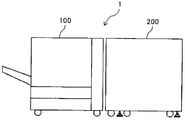
図1は、本実施形態の画像形成システム1の概略構成図である。
図1に示すように、画像形成システム1は、シートに画像を形成する画像形成手段としての画像形成装置100と、画像形成装置にシートを給送するシート給送装置200とを備えている。シート給送装置200は、画像形成装置100本体の側面に設けられている。
Hereinafter, an embodiment of a sheet feeding device to which the present invention is applied will be described.
FIG. 1 is a schematic configuration diagram of the
As shown in FIG. 1, the
まず、本実施形態のシート給送装置を適用可能なプリンター及び、同等の作像機能を有する複写機などの画像形成装置の全体構成及び動作について説明する。
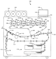
図2は、本実施形態に係る画像形成装置100の概略構成図である。
この画像形成装置100は、イエロー(Y),マゼンタ(M),シアン(C),黒(K)の4色のトナーを用いるフルカラープリンタ及び、同等の作像機能を有するフルカラー複写機である。図2に示すように、装置本体内の上部にそれぞれ各色トナーで作像を行う4つの作像ユニット101Y,101M,101C,101Kを並べて配置している。各作像ユニット101Y,101M,101C,101Kの構成とその動作は実質的に同一であるため、ここでは色を示す符号(Y,M,C,K)を省略して作像ユニットについて説明する。作像ユニット101においては、像担持体としての感光体ドラム102の周囲に、帯電器103,現像装置104,クリーニング装置105等が配置されている。また、感光体ドラム102の上方に位置して、露光手段107が配置されている。
First, the overall configuration and operation of an image forming apparatus such as a printer to which the sheet feeding apparatus of the present embodiment can be applied and a copying machine having an equivalent image forming function will be described.
FIG. 2 is a schematic configuration diagram of the
The
4つの作像ユニット101Y,101M,101C,101Kの下方には、複数の支持ローラに掛け回された中間転写ベルト108が配置されている。中間転写ベルト108は、支持ローラの一つが駆動手段によって回転駆動されることにより、矢印A方向に走行駆動される。その中間転写ベルト108を挟んで各作像ユニットの感光体ドラム102に対向するように、一次転写手段としての転写ローラ106が配置されている。
Below the four
各作像ユニット101においては、感光体ドラム102が図中反時計回りに回転駆動され、帯電器103によって感光体表面が所定の極性に均一に帯電される。次いでその帯電面に、露光手段107から出射される光変調されたレーザビームが照射され、これによって感光体ドラム102上に静電潜像が形成される。その静電潜像は、現像装置104から付与されるトナーによって現像され、トナー像として可視化される。各作像ユニットで形成されたイエロー,マゼンタ,シアン,黒の各色トナー像は、中間転写ベルト108上に順次重ね合わされて転写される。
In each
一方、装置本体の下部には収容トレイ114a及び114bを有する給送部114が設けられており、この給送部114あるいは画像形成装置100に装着される後述するシート給送装置200のいずれかから記録媒体として例えば転写紙が給送される。給送された転写紙は、レジストローラ111に向けて矢印Bの如く搬送される。
On the other hand, a
レジストローラ111に突き当てられて一旦停止された転写紙は、中間転写ベルト108上のトナー像とのタイミングを取ってレジストローラ111より送出され、二次転写ローラ109と中間転写ベルト108とが接する二次転写部に送り込まれる。その二次転写ローラ109にトナーの帯電極性と逆極性の電圧が印加され、これによって中間転写ベルト108上の重ねトナー像(フルカラー画像)が転写紙上に転写される。トナー像転写後の転写紙は、搬送ベルト112により定着装置113へ搬送され、定着装置113にて熱と圧力によりトナーが転写紙に定着される。トナー像定着後の転写紙は、矢印Cで示すように機外に排出され、排紙トレイ上に排紙される。
The transfer paper that has been abutted against the resist roller 111 and temporarily stopped is sent out from the resist roller 111 at the timing of the toner image on the
なお、片面印刷で裏面排紙(フェイスダウン排紙)する場合は、シート反転部115を経て矢印Cで示すように機外に排出することで、シートの表裏が逆転される。また、両面印刷の場合は、定着後のシートを両面反転部116を経て再給送路117よりレジストローラ111へと再給送し、シート裏面に中間転写ベルト108よりトナー像が転写される。トナー像転写後のシートは定着装置113で定着が行われ、片面印刷時と同じように定着装置113から矢印Cで示すように、あるいはシート反転部115を経て矢印Cで示すように機外に排出され、排紙トレイ上に排紙される。シート搬送方向を切り替えるための切替爪118,119が適宜配置されている。
In the case of single-sided printing, backside paper ejection (face-down paper ejection) is performed, and the front and back sides of the sheet are reversed by ejecting the sheet to the outside of the machine as shown by an arrow C through the
モノクロ印刷の場合は、本例の画像形成装置100では、黒(K)の作像ユニット101Kのみを用いてトナー像を作像し、そのトナー像を中間転写ベルト108を介して転写紙上に転写する。トナー像定着後のシートの扱いは、フルカラー印刷の場合と同様である。
In the case of monochrome printing, in the
なお、装置本体の上面には、各作像ユニットの現像装置104に供給するトナーを収納した各色トナーボトル121をセットするトナーボトルセット部120が設けられている。また、表示部122及び操作パネル123を有する操作部124も装置本体の上面に設けられている。さらに、装置本体の図において右側の側面には、後述するシート給送装置(図3参照)からのシート搬入部Dが設けられている。シート搬入部Dにおいては、シートを受け入れる開口125と、シートを搬送する搬送手段126が設けられている。
A toner
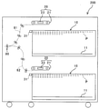
図3は、装置本体の側面に設けられる本実施形態のシート給送装置200の概略説明図である。
シート給送装置200は、上下2段の収容トレイ10を備える。各収容トレイ10は、シート束Pを積載するシート積載部であるシート積載台11を備えている。本実施形態においては、各収容トレイ10は、最大2500枚程度のシートを収納可能となっている。なお、シートとしては、紙、コート紙、ラベル紙、OHPシート、フィルム等を含む。各収容トレイ10の上方には、収容トレイ10に積載されたシートを分離・給送する給送ユニット20がそれぞれ配置されている。この給送ユニット20は、吸着搬送手段である吸着ベルト21及び吸引装置23を備えている。
FIG. 3 is a schematic explanatory view of the
The
下側の収容トレイ10に積載されたシートは、下搬送路82を通って、出口ローラ対80によって、画像形成装置100本体へ搬送される。上側の収容トレイ10に積載されたシートは、上搬送81を通って、出口ローラ対80によって、画像形成装置100本体へ搬送される。
The sheet loaded on the
図4は、収容トレイ10近傍の概略斜視図である。
給送ユニット20の吸着ベルト21は、2本の張架ローラ22a,22bにより張架されており、ベルトの表面側から裏面側まで貫通する吸引孔が周方向の全域に設けられている。また、吸着ベルト21の内部には、吸引装置23が設けられている。吸引装置23は、空気の流路であるエアダクト通じて空気を吸引する吸引手段である吸引ファンに接続されており、吸引装置23により下方に負圧を発生させることで、吸着ベルト21の下面にシートを吸着させるように作用する。この吸引装置23については後ほど詳述する。
FIG. 4 is a schematic perspective view of the vicinity of the
The
また、収容トレイ10には、シート束Pの上部のシートに対して空気を吹き付ける送風装置17を備える。この送風装置17は、フロント送風装置12とサイド送風装置14とを有している。
フロント送風装置12は、シート束Pの上部の先端(給送方向下流側端部)に対して空気を送風するものである。このフロント送風装置12には、シート束Pを浮上させる方向に空気を案内する浮上ノズル、最上位の浮上シートとそれ以外のシートを分離する方向に空気を案内する分離ノズル、及び、浮上ノズルと分離ノズルとにそれぞれ空気を送り込む2つの送風ファン(以下、単に送風ファンという)15が配置されている。この各ノズルのうち、浮上ノズルから図中矢印a1で示す向きに送風される空気を浮上エア、分離ノズルから図中矢印a2で示す向きに送風される空気を分離エアと呼ぶ。浮上エア及び分離エアは、シート束Pの上部の先端(給送方向下流側端部)と対向する箇所から吐出され、シート束Pの上部の先端(給送方向下流側端部)に吹き付けられる。
Further, the
The
また、サイド送風装置14は、一対のサイドフェンス13に設けられ、シート束Pの上部の側面に対して図中矢印bで示す向きに空気を送風するものである。このサイド送風装置14には、シート束Pを捌き、浮上させる方向に空気を案内するサイド浮上ノズルが配置されており、このノズルから図中矢印bで示す向きに送風される空気をサイドエアと呼ぶ。このサイドエアは、各サイドフェンス13のシート束Pの上部と対向する箇所に設けられた吐出口から吐出され、シート束Pの上部の側面に吹き付けられる。フロント送風装置12と、一対のサイドフェンス13の吐出口とから吹き付けられた空気により、シート束の上部のシートが浮上する。
また、収容トレイ10には、シート積載台11に積載されたシート束Pの後端を揃えるエンドフェンス25を設けている。
Further, the
Further, the
次に、吸引装置23について詳述する。
図5は、給送ユニット20の裏面から見た概略構成図である。
図5に示すように、吸引装置23は、吸着ベルト21の内部に設けられており、吸着搬送手段が前記最上位シートを吸着するシート吸引部30と吸引ファンとの間をエアダクト41によって接続している。吸引ファンによって吸引された吸引エアは、図中矢印c1及び矢印c2の向きに流れる。
Next, the
FIG. 5 is a schematic configuration diagram seen from the back surface of the
As shown in FIG. 5, the
図6は、吸引装置23のシャッターバルブ42の開状態を示す概略構成図である。(a)はエアダクトの内部を示す斜視図、(b)はエアダクトをx軸向きに見た側面図、(c)はエアダクトのz軸向きにから見た図である。
図7は、同シャッターバルブ42の閉状態を示す概略構成図である。(a)はエアダクトの内部を示す斜視図、(b)はエアダクトをx軸向きに見た側面図、(c)はエアダクトのz軸向きにから見た図である。
図6(a)に示すように、本実施形態の吸引装置23においては、エアダクト41内部に、エアダクト41内の通気を遮断する遮断手段であるシャッターバルブ42が設けられている。
FIG. 6 is a schematic configuration diagram showing an open state of the
FIG. 7 is a schematic configuration diagram showing a closed state of the
As shown in FIG. 6A, in the
このシャッターバルブ42は、引張スプリングを介してソレノイドと接続しており、後述する制御部60によって制御されるソレノイドのON・OFFによって、エアダクト41内の吸引エアの遮断・開放が切り替えられる。
詳しくは、シャッターバルブ42は、ソレノイドが無通電状態でソレノイド吸引力は作用していない状態、すなわち、OFF状態では、シャッターバルブ42がスプリングで引っ張られた状態となり、エア吸引方向に対し水平にバルブが配置されている開状態となる。この状態で吸引ファンを駆動させることで、シート吸引部30から図7(a)中矢印c3及び矢印c4示す向きに吸引エアが流れる。一方、ソレノイドが完全に吸引した状態、すなわち、ON状態では、図7(a)に示すように、吸引ファンによる吸引エアがエアダクト41内での通気を遮断する閉状態となる。この状態で吸引ファンが駆動すると、図中矢印c4で示す吸引エアがシャッターバルブ42によって遮断される。
The
Specifically, the
また、図6(b)に示すように、エアダクト41の側壁には、エアダクト内と外部とを貫通するリーク穴44が設けられている。シャッターバルブ42の幅方向両端部には、エアダクト41に設けられたリーク穴44を塞ぐ遮蔽部42aが設けられており、シャッターバルブ42が開状態であるときは、遮蔽部42aによってリーク穴が塞がれる。一方、シャッターバルブ42が閉状態であるときは、遮蔽部42aの位置がシャッターバルブ42の回転とともに移動することで、リーク穴44が開放され、シート吸引部の吸引静圧を下げる役割を示す。
Further, as shown in FIG. 6B, a
次に、本実施形態の給送制御について説明する。
図8は、シート給送装置200における制御系の要部構成の一例を示すブロック図である。
図8に示すように、シート給送装置200の制御手段としての制御部60には、フロント送風装置12及びサイド送風装置14のそれぞれに向けて空気を送風する送風装置17や、吸引装置23の吸引ファン61と吸着ベルト21や、シャッターバルブ42等を動作させるソレノイド43が接続されている。また、シート給送装置の稼働状態を表示する稼働状態表示手段である給送動作中LED62や、シート積載台11を昇降させる昇降手段である昇降駆動モータ19も接続されている。
Next, the feed control of the present embodiment will be described.
FIG. 8 is a block diagram showing an example of the configuration of a main part of the control system in the
As shown in FIG. 8, the
次に、吸着搬送装置によってシートを1枚ずつ給送する場合の動作について説明する。
図9は、給送動作の一例を示すフローチャートである。
画像形成装置の操作部などにより、シート給送装置200の収容トレイ10にセットされたシートを用いた画像形成指示を画像形成装置の上位コントローラが受ける。すると、シート給送装置200の制御部60に給送指示や、収容トレイ10のシート積載台11に積載されたシートの種類などの情報が、上位コントローラから送信される。制御部60は、給送指示を受信したら、吸着ベルト21を停止した状態で、送風装置17の駆動を開始する。これにより、図4に示すように、フロント送風装置12の吐出口から矢印a1方向に空気が吐出し、シート束の上部の前端部に空気が吹き付けられる。また、一対のサイドフェンス13の吐出口から空気が吐出し、シート束の上部の側端部に空気が吹き付けられることで、シート束Pの上部のシートが浮上する。
Next, the operation when the sheets are fed one by one by the suction transfer device will be described.
FIG. 9 is a flowchart showing an example of the feeding operation.
An upper controller of the image forming apparatus receives an image forming instruction using a sheet set in the
また、これと同時に吸引ファン61の駆動を開始し、吸引装置23による吸引を開始する(ステップ1)。吸引装置23が吸引を開始することで、吸引装置23の下方に負圧が発生し、浮上した最上位シートP1を吸着ベルト21に吸着する。そして、吸着ベルト21を回転させることで給送を開始する(ステップ2)。
次に、制御部60は、給送開始から所定時間が経過したか否かを判断する(ステップ3)。所定時間が経過すると(ステップ3のYes)、シャッターバルブ42を閉じ(ステップ4)、吸着ベルト21を停止させる(ステップ5)。
At the same time, the
Next, the
このように、給送開始から所定時間経過後に吸着ベルト21を停止させることで、最上位シートの後端が吸着開口部を抜けた際に、収容トレイ10内に積載された次のシートが吸着ベルト21に吸着され、意図しないタイミングで吸着搬送されてしまうのを防ぐことができる。
また、給送開始から所定時間経過後にシャッターバルブ42を閉じることで、吸着ベルト21へのシートの吸着を停止することができる。これにより、吸着ベルト21に吸着されているシートが、搬送手段によって搬送される際に停止した吸着ベルト21と接触することで生じる搬送キズやこすれ等を防止することができる。
In this way, by stopping the
Further, by closing the
次に、制御部60は、吸着ベルト21を停止させてから所定時間が経過したか否かを判断する(ステップ6)。そして、所定時間が経過すると(ステップ6のYes)、次のシートを搬送するために、シャッターバルブ42を開き(ステップ7)、給送開始要求があるか否かを判断する(ステップ8)。このように、給送開始要求の有無にかかわらずシャッターバルブ42を開けることで、いつ給送開始要求されても吸着搬送が可能な状態にすることができ、高い生産性を得ることが可能となる。
そして、給送開始要求がある場合(ステップ8のYes)、ステップ2からステップ7までの動作を繰り返し、次のシートを搬送する。給送開始要求がない場合(ステップ8のNo)、吸着搬送終了動作となり、後述する吸着搬送終了後のフローを実行する。
Next, the
Then, when there is a request to start feeding (Yes in step 8), the operations from step 2 to step 7 are repeated, and the next sheet is conveyed. If there is no request to start feeding (No in step 8), the suction transport end operation is performed, and the flow after the suction transport ends, which will be described later, is executed.
次に、本実施形態の特徴部である、吸着搬送終了後の動作について説明する。
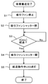
図10は、吸着搬送完了後の動作の一例を示すフローチャートである。
吸着搬送装置による吸着搬送完了すると、制御装置は、吸引ファン61を停止し(ステップ1)、シャッターバルブ42を閉じる(ステップ2)。このとき、シャッターバルブ42によって塞がれていたリーク穴が開放される。特許文献1のシート給送装置では、吸着部の負圧が開放されないため、シートが吸着部から剥がれるまでにさらに時間がかかってしまうという問題があった。本実施形態では、吸引エアによるシートの吸着が遮断されると同時に、シート吸引部30内の負圧も開放されるため、素早くシートを引き剥がすことが可能となる。
Next, the operation after the end of suction transfer, which is a feature of the present embodiment, will be described.
FIG. 10 is a flowchart showing an example of the operation after the suction transfer is completed.
When the suction transfer by the suction transfer device is completed, the control device stops the suction fan 61 (step 1) and closes the shutter valve 42 (step 2). At this time, the leak hole blocked by the
次に、制御部60は、シャッターバルブ42を閉めてから所定時間が経過したか否かを判断する(ステップ4)。所定時間が経過すると(ステップ4のYes)は、シャッターバルブ42を開ける動作を実行する。このように、所定時間経過後にシャッターバルブ42を開けておくことで、印刷開始が要求されて吸引ファン61による吸引動作を開始する際に、シャッターバルブ42を開ける動作を省略することができる。
Next, the
そして、シャッターバルブ42を開けるのと同時に、給送動作中LED62を消灯し(ステップ5)、ユーザーへ収容トレイ10を開けていいことをアナウンスする。
このように、収容トレイ10を開く際にシャッターバルブ42が開いた状態、すなわちソレノイドがOFFの状態であることで、温度上昇したソレノイドにユーザーが触れるおそれがなく、安全である。
Then, at the same time as opening the
As described above, when the
次に、シート給送装置の別の例について詳述する。
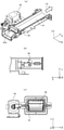
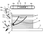
図11は、シート給送装置の別の例の模式図である。図12は、下方吸引ファンとシャッター機構との模式図である。
図11に示すように、給送ユニット20は、上述した例と同様に、2本の張架ローラ22a,22bにより張架された吸着ベルト21と、その吸着ベルト21の内部に設けられた吸引装置23とから構成されている。吸引装置23は、空気の流路であるエアダクトを通じて空気を吸引する吸引手段である吸引ファンに接続されており、吸引装置23により下方に負圧を発生させることで、吸着ベルト21の下面にシートを吸着させるように作用する。
Next, another example of the seat feeding device will be described in detail.
FIG. 11 is a schematic diagram of another example of the seat feeding device. FIG. 12 is a schematic view of the lower suction fan and the shutter mechanism.
As shown in FIG. 11, the
また、フロント送風装置12には、シートを浮上させる方向に空気を吐出する浮上ノズル51と、最上位の浮上シートとそれ以外のシートを分離する方向に空気を吐出する分離ノズル52とが配置されている。浮上ノズル51や分離ノズル52からは、浮上エアや分離エアが図11中矢印a1、a2で示す向きに吐出され、シート束Pの上部の先端(給送方向下流側端部)に吹き付けられる。これにより、シート束の上部のシートが浮上する。フロント送風装置12の浮上ノズル51には、図11に示すように、送風ファンとの間にエアダクト51aが接続されている。さらに、フロント送風装置12の分離ノズル52には、図11に示すように、送風ファンとの間にエアダクト52aが接続されている。エアダクト51a,52aの内部には、そのエアダクト内の通気を遮断・開放する遮断手段であるシャッターバルブ51b,52bが設けられている。
Further, the
さらに、フロント送風装置12には、最上面シート近傍のシートに対し下方に向かう吸引力を作用させるよう吸引する下方吸引ノズル53が配置されている。この下方吸引ノズル53は、図12(a)、(b)に示すように、エアダクト53aを通じて空気を吸引する下方吸引手段である下方吸引ファン54に接続されている。そして、下方吸引ノズル53には、最上面シート近傍の空気が図11中の矢印a3で示す方向に吸引される。吸引装置23のエアダクト53aの内部には、そのエアダクト内の通気を遮断・開放する下方吸引エア開閉手段であるシャッターバルブ53bが設けられている。
Further, the
また、図12(b)に示すように、ソレノイド55が無通電状態でソレノイド吸引力は作用していない状態、すなわち、OFF状態では、シャッターバルブ53bがスプリング56で引っ張られた状態となり、エアダクト53aの通気を遮断する閉状態となる。ソレノイド55がプランジャ55aを完全に吸引した状態、すなわち、ON状態では、プランジャ55aに接続されたレバー57を回動させ、シャッターバルブ53bを図12(b)中の矢印dで示す向きに移動させる。それにより、エアダクト53aの通気を遮断していた状態が開放され、図12中の矢印eで示す向きに吸引エアが流れる開状態となる。
Further, as shown in FIG. 12B, in the state where the
次に、図13は、シート給送装置200における制御系の要部構成の別の例を示すブロック図である。
図13に示すように、シート給送装置200の制御手段としての制御部60には、フロント送風装置12及びサイド送風装置14のそれぞれに向けて空気を送風する送風装置17や、吸引装置23の吸引ファン61と吸着ベルト21や、シャッターバルブ42、53b等を動作させるソレノイド43、55が接続されている。また、シート給送装置の稼働状態を表示する稼働状態表示手段である給送動作中LED62、シート積載台11を昇降させる昇降手段である昇降駆動モータ19や下方吸引手段である下方吸引ファン54も接続されている。
Next, FIG. 13 is a block diagram showing another example of the configuration of the main part of the control system in the
As shown in FIG. 13, the
次に、図11のシート給送装置によってシートを1枚ずつ給送する場合の動作について説明する。
図14は、図11のシート給送装置による給送動作の例を示すフローチャートである。
画像形成装置の操作部などにより、図13のシート給送装置200の収容トレイ10にセットされたシートを用いた画像形成指示を画像形成装置の上位コントローラが受けると、シート給送装置200の制御部60に給送指示や、収容トレイ10のシート積載台11に積載されたシートの種類などの情報が、上位コントローラから送信される。制御部60は、給送指示を受信したら、吸着ベルト21を停止した状態で、送風装置17の駆動を開始する。これと同時に吸引ファン61の駆動を開始し、吸引装置23による吸引を開始する。吸引装置23が吸引を開始することで、吸引装置23の下方に負圧が発生し、浮上した最上位のシートを吸着ベルト21に吸着する。さらに、これらと同時に下方吸引ファン54の駆動を開始し、下方吸引を開始する(ステップ1)。以上により、給送準備を開始する(ステップ2)。
Next, the operation when the sheets are fed one by one by the sheet feeding device of FIG. 11 will be described.
FIG. 14 is a flowchart showing an example of a feeding operation by the sheet feeding device of FIG.
When the host controller of the image forming apparatus receives an image forming instruction using the sheet set in the
このとき、図11のシャッターバルブ42、シャッターバルブ51b及びシャッターバルブ52bをそれぞれ開けて、かつ、シャッターバルブ53bを閉じる(ステップ3)。それにより、図11に示すように、フロント送風装置12の浮上ノズル51から矢印a1方向に空気が吐出し、シート束の上部の前端部に空気が吹き付けられる。また、一対のサイドフェンス13の吐出口から空気が吐出し(図4参照)、シート束の上部の側端部に空気が吹き付けられることで、シート束の上部のシートが浮上する。さらに、フロント送風装置12の分離ノズル52から矢印a2方向に空気が吐出し、最上位の浮上シートとそれ以外のシートを分離する。そして、吸引装置23により下方に負圧を発生させる。制御部60は、給送開始から所定時間(X)が経過したか否かを判断する(ステップ4)。所定時間が経過すると(ステップ4のYes)、吸着ベルト21の下面にシートが吸着される。そして、シャッターバルブ51b、52bをそれぞれ閉じ、かつ、シャッターバルブ42、53bをそれぞれ開ける(ステップ5)。以上により、給送準備が完了する(ステップ6)。
At this time, the
そして、吸着ベルト21を回転させることで給送を開始する(ステップ7)。制御部60は、給送開始から所定時間(X)が経過したか否かを判断する(ステップ8)。所定時間(X)が経過すると(ステップ8のYes)、シャッターバルブ51b、52bをそれぞれ開け、かつ、シャッターバルブ42、53bを閉じる(ステップ9)。このように、給送開始要求の有無にかかわらずステップ9の動作を行うことで、次のシートの浮上・分離を行い、いつ給送開始要求されても吸着搬送が可能な状態にすることができ、高い生産性を得ることが可能となる。そして、吸着ベルト21を停止させる(ステップ10)。給紙開始要求がある場合(ステップ11のYes)、ステップ2からステップ10までの動作を繰り返す。給送開始要求がない場合(ステップ11のNo)、吸着搬送は終了となり、後述する吸着搬送完了時のフローを実行する。
Then, feeding is started by rotating the suction belt 21 (step 7). The
次に、本実施形態の特徴部である、吸着搬送完了時の別の動作について説明する。
図15は、吸着搬送完了時の別の動作の一例を示すフローチャートである。図16は、シート給送装置におけるシャッターバルブの開閉とシートの挙動とを示す模式図である。図17は、下方吸引力を上げたときのシートの挙動を示す模式図である。図18は、シート積載台を下降させたときのシートの挙動を示す模式図である。
Next, another operation at the completion of suction transfer, which is a feature of the present embodiment, will be described.
FIG. 15 is a flowchart showing an example of another operation when the suction transfer is completed. FIG. 16 is a schematic diagram showing the opening and closing of the shutter valve and the behavior of the seat in the seat feeding device. FIG. 17 is a schematic view showing the behavior of the seat when the downward suction force is increased. FIG. 18 is a schematic view showing the behavior of the seat when the seat loading platform is lowered.
吸着搬送装置による吸着搬送完了すると、図13の制御部60は、吸引ファン、浮上ファン及び分離ファンを停止する指示動作を行う(ステップ1)。下方吸引ファンは駆動したままにする。このとき、吸引ファン、浮上ファン及び分離ファンの回転停止の指示動作が行われても、各ファンの回転減衰分のエアが出てしまう。そのため、一定時間はそのエアの影響を受けてしまう。そこで、図16に示すように、制御部60により各ファンの回転停止の指示動作を行うと同時に、シャッターバルブ42、51b、52bをそれぞれ閉じることにより、各ファンの回転減衰分のエア出力を遮断する。さらに、シャッターバルブ53bを開けることで、収容トレイのシート積載台へのシートの落下を促進する(ステップ2)。
When the suction transfer by the suction transfer device is completed, the
また、図17に示すように、下方吸引ファンの回転数を給紙動作中よりも上げて下方吸引力を高め(ステップ3)、シート積載台の底板へのシート落下をより促進する。さらには、図18に示すように、シート積載台を下降させ(ステップ4)、シートを吸引ファン、浮上ファン及び分離ファンの回転減衰分のエアから遠ざけることで、そのエアによる影響を抑制する。それにより、収容トレイのシート積載台へのシートの落下をよりいっそう促進させることができる。本実施形態では、吸引エアによるシートの吸着が遮断されると同時に、シート吸引部30内の負圧も開放され、かつ、シートを下方へ吸引するため、より素早くシートを吸着ベルトから引き剥がすことが可能となる。
Further, as shown in FIG. 17, the rotation speed of the lower suction fan is increased more than during the paper feeding operation to increase the downward suction force (step 3), and the sheet is further promoted to fall to the bottom plate of the seat loading platform. Further, as shown in FIG. 18, the seat loading platform is lowered (step 4), and the seat is moved away from the air corresponding to the rotational attenuation of the suction fan, the levitation fan, and the separation fan to suppress the influence of the air. As a result, the falling of the seat on the seat loading platform of the storage tray can be further promoted. In the present embodiment, the suction of the sheet by the suction air is blocked, and at the same time, the negative pressure in the
次に、制御部60は、シャッターバルブ42、51b、52bをそれぞれ遮断してから所定時間(X)が経過したか否かを判断する(ステップ5)。所定時間(X)が経過すると(ステップ4のYes)は、シャッターバルブ42を開ける動作を実行する。このようにすることで、印刷開始が要求されて吸引ファン61による吸引動作を開始する際に、シャッターバルブ42、51b、52bを開ける動作を省略することができる。そして、下方吸引ファンをOFFにする(ステップ7)のと同時に、給送動作中LED62を消灯し(ステップ8)、ユーザーへ収容トレイ10を開けていいことをアナウンスする。
Next, the
このように、吸着搬送完了時に下方吸引エアによってシートをシート積載台への落下を促進させることで、シートの再浮上や再吸着を抑制できるとともに、シート積載台引き出し時にシートにダメージを与えず、シート積載台引き出す際の待ち時間を短縮することができる。 In this way, by promoting the sheet to fall to the seat loading platform by the downward suction air when the suction transfer is completed, the sheet can be suppressed from re-floating and re-adsorption, and the sheet is not damaged when the sheet loading platform is pulled out. It is possible to shorten the waiting time when pulling out the seat loading platform.
以上に説明したものは一例であり、次の態様毎に特有の効果を奏する。
(態様A)
シート束を積載するシート積載台11等のシート積載台と、吸引ファン61等の吸引手段による吸引エアによって前記シート束の最上位シートを吸着し、吸着したシートを搬送する吸着ベルト21、吸引装置23等の吸着搬送手段とを備えたシート給送装置200等のシート給送装置において、前記吸着搬送手段が前記最上位シートを吸着するシート吸引部30等のシート吸引部まで前記吸引手段による吸引エアを導くエアダクト41等のエアダクトと、前記エアダクト内の前記吸引エアを遮断可能なシャッターバルブ42等の遮断手段と、前記遮断手段による前記吸引エアの遮断動作を制御する制御部60等の制御手段とを備え、前記制御手段が、前記吸着搬送手段による前記最上位シートの搬送終了時に、前記遮断手段によって前記吸引エアを遮断させることを特徴とする。
What has been described above is an example, and has a unique effect in each of the following aspects.
(Aspect A)
A seat loading platform such as a
本態様においては、吸着搬送完了時に遮断手段によって吸引エアを遮断するため、吸着搬送完了時に、吸引手段の停止と同時に遮断手段によって吸引エアを遮断することが可能となる。これにより、遮断手段を設けていない従来のシート給送装置と比べて、吸引手段の停止動作中の吸引エアによるシートの吸引を素早く遮断することが出来るので、吸着搬送手段に吸着されたシートが吸着搬送手段から剥がれるまでの時間を短縮することができる。したがって、シート積載台引き出し時にシートにダメージを与えず、待ち時間を短縮することができる。 In this embodiment, since the suction air is shut off by the shutoff means when the suction transport is completed, the suction air can be shut off by the shutoff means at the same time as the suction means is stopped when the suction transport is completed. As a result, the suction of the sheet by the suction air during the stop operation of the suction means can be quickly blocked as compared with the conventional sheet feeding device not provided with the blocking means, so that the sheet sucked by the suction transport means can be blocked. It is possible to shorten the time until the suction transport means is peeled off. Therefore, the seat is not damaged when the seat loading platform is pulled out, and the waiting time can be shortened.
(態様B)
態様Aのシート給送装置において、シート給送装置200等の本体装置の稼働状態を表示する給送動作中LED62等の稼働状態表示手段を備え、制御部60等の前記制御手段は、エアダクト41等の前記エアダクト内の前記吸引エアがシャッターバルブ42等の前記遮断手段によって遮断されてから所定時間が経過した時点で、本体装置が非稼動中であることを前記稼働状態表示手段に表示させることを特徴とする。
本態様においては、上記実施形態について説明したように、温度上昇したソレノイドなどにユーザーが触れるおそれがなく、安全である。
(Aspect B)
In the seat feeding device of the aspect A, the operating state display means such as the
In this embodiment, as described in the above embodiment, there is no risk of the user touching the solenoid whose temperature has risen, and it is safe.
(態様C)
態様A又はBのシート給送装置において、前記シート積載台を昇降する昇降駆動モータ19等の昇降手段と、前記シート束のシート搬送方向先端位置を規制する突き当て板と、前記シート束のシート先端方向からエアを吹き付けてシートを浮上させるフロント送風装置12等の浮上送風手段と、前記送風手段により浮上したシートのシート先端側にエアを吹き付け浮上したシートを1枚ずつ分離するフロント送風装置12等の分離送風手段とを備え、吸着ベルト21、吸引装置23等の前記吸着搬送手段は、前記浮上したシートの最上位シートを吸着して搬送し、シャッターバルブ42等の前記遮断手段は、ソレノイド43等のソレノイドと引張スプリングを用いてエアダクト41等の前記エアダクト内の前記吸引エアを遮断し、制御部60等の前記制御手段は、前記ソレノイドを介して前記遮断手段によって前記吸引エアを遮断させる。
(Aspect C)
In the sheet feeding device of the aspect A or B, an elevating means such as an elevating
(態様D)
態様A~Cいずれか一のシート給送装置において、前記エアダクトの壁面に該エアダクトの内部と外部とを貫通するリーク穴44等のリーク穴を備え、シャッターバルブ42等の前記遮断手段によって前記吸引エアが遮断された時に、前記リーク穴が開放されることを特徴とする。
本態様においては、上記実施形態について説明したように、より早く、吸着ベルトからシートを引き剥がすことができる。したがって、吸着搬送完了時に、吸着されているシートを素早くシート積載台に戻すことができる。
(Aspect D)
In the sheet feeding device of any one of embodiments A to C, the wall surface of the air duct is provided with a leak hole such as a
In this embodiment, as described above, the sheet can be peeled off from the suction belt more quickly. Therefore, when the suction transfer is completed, the sucked sheet can be quickly returned to the seat loading platform.
(態様E)
態様Dのシート給送装置において、シャッターバルブ42等の前記遮断手段によって前記吸引エアが遮断されていない時に、リーク穴44等の前記リーク穴が前記遮断手段によって塞がれ、前記遮断手段によって前記吸引エアが遮断された時に、前記遮断手段によって前記リーク穴が開放されることを特徴とする。
本態様においては、遮断手段によってリーク穴の遮断及び開放が切り替えられることで、リーク穴を遮断・開放するための専用の機構を必要としない。
(Aspect E)
In the seat feeding device of the aspect D, when the suction air is not shut off by the shutoff means such as the
In this embodiment, the leak hole is switched between blocking and opening by the blocking means, so that a dedicated mechanism for blocking and opening the leak hole is not required.
(態様F)
(態様A)のシート給送装置において、前記シート積載台側へ向かう下方吸引エアによってシートを吸引する下方吸引手段と、該下方吸引手段による前記下方吸引エアの通路であるエアダクト53a等の下方吸引エアダクトと、該下方吸引エアダクト内の前記下方吸引エアを開閉可能なシャッターバルブ53b等の下方吸引エア開閉手段とを備え、制御部60等の前記制御手段は、前記吸着搬送手段によるシートの搬送終了時に、前記下方吸引エア開閉手段によって前記下方吸引エアダクト内の前記下方吸引エアを開放させることを特徴とする。
本態様においては、上記実施形態について説明したように、より早く、吸着ベルトからシートを引き剥がすことができる。したがって、吸着搬送完了時に、吸着されているシートを素早くシート積載台に戻すことができる。
(Aspect F)
In the seat feeding device of (Aspect A), the lower suction means for sucking the sheet by the lower suction air toward the seat loading platform side and the lower suction means such as the
In this embodiment, as described above, the sheet can be peeled off from the suction belt more quickly. Therefore, when the suction transfer is completed, the sucked sheet can be quickly returned to the seat loading platform.
(態様G)
(態様F)のシート給送装置において、前記制御手段は、前記吸着搬送手段によるシートの搬送終了時に、前記下方吸引手段による吸引力を高めることを特徴とする。
本態様においては、上記実施形態について説明したように、シート積載台へのシート落下を促進させることができる。
(Aspect G)
In the sheet feeding device of (Aspect F), the control means is characterized in that the suction force by the downward suction means is increased at the end of the transfer of the sheet by the suction transfer means.
In this embodiment, as described above, it is possible to promote the falling of the seat onto the seat loading platform.
(態様H)
(態様F)又は(態様G)のシート給送装置において、前記制御手段は、前記吸着搬送手段によるシートの搬送終了時に、前記シート積載台を下降させることを特徴とする。
本態様においては、上記実施形態について説明したように、シート積載台を下降させ、シートを吸引エアから遠ざけることで、そのエアによる影響を抑制することができる。したがって、シート積載台へのシート落下をより促進させることができる。
(Aspect H)
In the sheet feeding device according to (Aspect F) or (Aspect G), the control means is characterized in that the sheet loading platform is lowered at the end of the transfer of the sheet by the suction transport means.
In this embodiment, as described in the above embodiment, by lowering the seat loading platform and moving the seat away from the suction air, the influence of the air can be suppressed. Therefore, it is possible to further promote the falling of the seat onto the seat loading platform.
(態様I)
シートに画像を形成する画像形成手段と、画像形成手段へ向けてシートを給送する給送手段とを備えた画像形成装置において、上記給送手段として、態様A~Hいずれか一のシート給送装置を用いたことを特徴とする。
本態様においては、収容トレイ引き出し時にシートにダメージを与えず、待ち時間を短縮することができる画像形成装置を提供することができる。
(Aspect I)
In an image forming apparatus including an image forming means for forming an image on a sheet and a feeding means for feeding the sheet to the image forming means, the sheet feeding means according to any one of aspects A to H is used as the feeding means. It is characterized by using a feeding device.
In this aspect, it is possible to provide an image forming apparatus capable of shortening the waiting time without damaging the sheet when the storage tray is pulled out.
(態様J)
少なくともシートに画像を形成する画像形成手段を備えた画像形成装置と、画像形成装置へ向けてシートを給送するシート給送装置とを備えた画像形成システムにおいて、上記シート給送装置として、態様A~Hいずれか一のシート給送装置を用いたことを特徴とする。
本態様においては、収容トレイ引き出し時にシートにダメージを与えず、待ち時間を短縮することができる画像形成システムを提供することができる。
(Aspect J)
In an image forming system including at least an image forming apparatus provided with an image forming means for forming an image on a sheet and a sheet feeding device for feeding the sheet to the image forming apparatus, the sheet feeding device is an embodiment. It is characterized in that a sheet feeding device of any one of A to H is used.
In this aspect, it is possible to provide an image forming system capable of shortening the waiting time without damaging the sheet when the storage tray is pulled out.
1 画像形成システム
10 収容トレイ
11 シート積載台
13 サイドフェンス
17 送風装置
19 昇降駆動モータ
20 給送ユニット
21 吸着ベルト
23 吸引装置
30 シート吸引部
41 エアダクト
42 シャッターバルブ
43 ソレノイド
44 リーク穴
51 浮上ノズル
51a エアダクト
51b シャッターバルブ
52 分離ノズル
52a エアダクト
52b シャッターバルブ
53 下方吸引ノズル
53a エアダクト
53b シャッターバルブ
54 下方吸引ファン
55 ソレノイド
55a プランジャ
56 スプリング
57 レバー
60 制御部
61 吸引ファン
62 給送動作中LED
100 画像形成装置
101 作像ユニット
102 感光体ドラム
103 帯電器
104 現像装置
105 クリーニング装置
107 露光手段
108 中間転写ベルト
200 シート給送装置
1
100
Claims (12)
吸引エアを発生する吸引手段と、
前記吸引エアによって前記シート束の最上位シートを吸着し、吸着したシートを搬送する吸着搬送手段と、
前記吸引手段による吸引エアを前記吸着搬送手段まで導くエアダクトと、
前記エアダクト内の前記吸引エアを遮断可能な遮断手段と、
前記シート積載台側へ向かう下方吸引エアによってシートを吸引する下方吸引手段と、
該下方吸引手段による前記下方吸引エアの通路である下方吸引エアダクトと、
該下方吸引エアダクト内の前記下方吸引エアを遮断もしくは開放する下方吸引エア開閉手段と、
シート給送装置を制御する制御手段とを備え、
前記制御手段は、前記吸着搬送手段によるシートの搬送終了時に、前記下方吸引エア開閉手段によって前記下方吸引エアダクト内の前記下方吸引エアを開放させることを特徴とするシート給送装置。 A seat loading platform for loading a bundle of seats and
A suction means that generates suction air and
A suction transport means for sucking the top sheet of the sheet bundle with the suction air and transporting the sucked sheet,
An air duct that guides the suction air from the suction means to the suction transfer means,
A shutoff means capable of shutting off the suction air in the air duct,
The downward suction means for sucking the seat by the downward suction air toward the seat loading platform side,
The lower suction air duct, which is the passage of the lower suction air by the lower suction means,
The lower suction air opening / closing means for shutting off or opening the lower suction air in the lower suction air duct, and the lower suction air opening / closing means.
Equipped with a control means to control the seat feeder,
The control means is a sheet feeding device characterized in that the lower suction air in the lower suction air duct is released by the lower suction air opening / closing means at the end of the transfer of the sheet by the suction transfer means.
前記遮断手段は、前記エアダクト内に設けられたシャッターバルブと、該シャッターバルブが該エアダクトの通路を開く開状態と該エアダクトの通路を閉じる閉状態とを切り替えるソレノイドを有することを特徴とするシート給送装置。 In the sheet feeding device according to claim 1,
The shutoff means includes a shutter valve provided in the air duct and a solenoid that switches between an open state in which the shutter valve opens the passage of the air duct and a closed state in which the shutter valve closes the passage of the air duct. Feeding device.
前記シート積載台を昇降する昇降手段と、前記シート束のシート搬送方向先端位置を規制する突き当て板と、前記シート束のシート先端方向からエアを吹き付けてシートを浮上させる浮上送風手段と、前記浮上送風手段により浮上したシートのシート先端側にエアを吹き付け浮上したシートを1枚ずつ分離する分離送風手段とを備えたことを特徴とするシート給送装置。 In the sheet feeding device according to claim 1 or 2.
The elevating means for raising and lowering the sheet loading platform, the abutting plate for regulating the position of the tip of the sheet bundle in the sheet transport direction, the levitation blowing means for blowing air from the direction of the tip of the sheet of the sheet bundle to levitate the sheet, and the above. A sheet feeding device characterized by being provided with a separate blowing means for separating the floating sheets one by one by blowing air on the sheet tip side of the sheet floated by the floating blowing means.
前記エアダクトの壁面に該エアダクトの内部と外部とを貫通するリーク穴が設けられ、前記遮断手段によって前記吸引エアが遮断された時に、前記リーク穴が開放されることを特徴とするシート給送装置。 In the sheet feeding device according to any one of claims 1 to 3.
A sheet feeding device characterized in that a leak hole penetrating the inside and the outside of the air duct is provided on the wall surface of the air duct, and the leak hole is opened when the suction air is blocked by the blocking means. ..
前記遮断手段によって前記吸引エアが遮断されていない時に、前記リーク穴が前記遮断手段によって塞がれることを特徴とするシート給送装置。 In the sheet feeding device according to claim 4,
A sheet feeding device, characterized in that the leak hole is closed by the shutoff means when the suction air is not shut off by the shutoff means.
前記エアダクトの壁面に該エアダクトの内部と外部とを貫通するリーク穴が設けられ、
前記シャッターバルブには前記リーク穴を塞ぐ遮蔽部が設けられており、
前記シャッターバルブが閉状態であるときは、前記遮蔽部が前記リーク穴を開放する位置にあることを特徴とするシート給送装置。 In the sheet feeding device according to claim 2,
A leak hole is provided on the wall surface of the air duct so as to penetrate the inside and the outside of the air duct.
The shutter valve is provided with a shielding portion that closes the leak hole.
A seat feeding device characterized in that when the shutter valve is in the closed state, the shielding portion is in a position where the leak hole is opened.
前記制御手段が、前記吸着搬送手段による前記最上位シートの搬送終了時に、前記遮断手段によって前記吸引エアを遮断させることを特徴とするシート給送装置。 In the sheet feeding device according to any one of claims 1 to 6.
A sheet feeding device, wherein the control means shuts off the suction air by the blocking means at the end of transporting the top sheet by the suction transporting means.
該シート給送装置の稼働状態を示す稼働状態表示手段を備え、
前記稼働状態表示手段は発光及び消灯が可能であり、
前記制御手段は、前記エアダクト内の前記吸引エアが前記遮断手段によって遮断されてから所定時間が経過した時点で、前記稼働状態表示手段を消灯させることを特徴とするシート給送装置。 In the sheet feeding device according to claim 7,
The sheet feeding device is provided with an operating state display means for indicating the operating state.
The operating status display means can emit light and turn off.
The control means is a sheet feeding device, characterized in that the operating state display means is turned off when a predetermined time has elapsed after the suction air in the air duct is shut off by the shutoff means.
前記制御手段は、前記吸着搬送手段によるシートの搬送終了時に、前記下方吸引手段による吸引力を高めることを特徴とするシート給送装置。 In the sheet feeding device according to any one of claims 1 to 8.
The control means is a sheet feeding device characterized in that the suction force of the downward suction means is increased at the end of the transfer of the sheet by the suction transfer means.
前記制御手段は、前記吸着搬送手段によるシートの搬送終了時に、前記シート積載台を下降させることを特徴とするシート給送装置。 In the sheet feeding device according to any one of claims 1 to 9.
The control means is a sheet feeding device characterized in that the seat loading platform is lowered at the end of transporting the sheet by the suction transporting means .
上記給送手段として、請求項1乃至10のいずれか一に記載のシート給送装置を用いたことを特徴とする画像形成装置。 In an image forming apparatus including an image forming means for forming an image on a sheet and a feeding means for feeding the sheet to the image forming means.
An image forming apparatus according to claim 1, wherein the sheet feeding device according to any one of claims 1 to 10 is used as the feeding means.
上記シート給送装置として、請求項1乃至10のいずれか一に記載のシート給送装置を用いたことを特徴とする画像形成システム。 At least in an image forming system including an image forming apparatus provided with an image forming means for forming an image on a sheet, and a sheet feeding device for feeding the sheet to the image forming apparatus.
An image forming system comprising the sheet feeding device according to any one of claims 1 to 10 as the sheet feeding device.
Priority Applications (1)
| Application Number | Priority Date | Filing Date | Title |
|---|---|---|---|
| US15/896,417 US10315870B2 (en) | 2016-05-18 | 2018-02-14 | Sheet feeding device, image forming apparatus incorporating the sheet feeding device, and image forming system incorporating the sheet feeding device |
Applications Claiming Priority (2)
| Application Number | Priority Date | Filing Date | Title |
|---|---|---|---|
| JP2016099952 | 2016-05-18 | ||
| JP2016099952 | 2016-05-18 |
Publications (3)
| Publication Number | Publication Date |
|---|---|
| JP2017210370A JP2017210370A (en) | 2017-11-30 |
| JP2017210370A5 JP2017210370A5 (en) | 2018-04-05 |
| JP7004232B2 true JP7004232B2 (en) | 2022-01-21 |
Family
ID=60474524
Family Applications (1)
| Application Number | Title | Priority Date | Filing Date |
|---|---|---|---|
| JP2017029639A Expired - Fee Related JP7004232B2 (en) | 2016-05-18 | 2017-02-21 | Sheet feeder, image forming device and image forming system |
Country Status (2)
| Country | Link |
|---|---|
| US (1) | US10315870B2 (en) |
| JP (1) | JP7004232B2 (en) |
Families Citing this family (9)
| Publication number | Priority date | Publication date | Assignee | Title |
|---|---|---|---|---|
| US10662009B2 (en) * | 2017-11-22 | 2020-05-26 | Ricoh Company, Ltd. | Sheet feeding device, image forming apparatus, and image forming system |
| JP7155724B2 (en) * | 2017-11-22 | 2022-10-19 | 株式会社リコー | Sheet feeding device, image forming device and image forming system |
| US11634291B2 (en) | 2019-09-27 | 2023-04-25 | Ricoh Company, Ltd. | Belt conveyance device, sheet feeding device, image forming apparatus, and image forming system |
| JP7417195B2 (en) | 2020-03-19 | 2024-01-18 | 株式会社リコー | Feeding device and image forming device |
| JP7622377B2 (en) | 2020-08-24 | 2025-01-28 | 株式会社リコー | Automatic conveying device, image reading device and image forming device |
| JP7616560B2 (en) * | 2020-11-25 | 2025-01-17 | 株式会社リコー | Sheet separating device and image forming apparatus |
| JP7750054B2 (en) | 2021-11-25 | 2025-10-07 | 株式会社リコー | Sheet feeding device and image forming apparatus |
| JP2023095169A (en) | 2021-12-24 | 2023-07-06 | 株式会社リコー | Paper feeder and image forming device |
| JP2024077981A (en) * | 2022-11-29 | 2024-06-10 | 株式会社リコー | Sheet feeding device and image forming apparatus |
Citations (10)
| Publication number | Priority date | Publication date | Assignee | Title |
|---|---|---|---|---|
| JP2000007174A (en) | 1998-04-24 | 2000-01-11 | Ricoh Co Ltd | Image forming device |
| US20050212198A1 (en) | 2004-03-29 | 2005-09-29 | Eastman Kodak Company | Method of operating a vacuum corrugated belt feeder to improve sheet acquisition from a feed supply |
| JP2007191293A (en) | 2006-01-20 | 2007-08-02 | Canon Inc | Sheet feeding apparatus and image forming apparatus |
| JP2008260617A (en) | 2007-04-12 | 2008-10-30 | Canon Inc | Sheet feeding apparatus and image forming apparatus |
| JP2010195588A (en) | 2009-01-30 | 2010-09-09 | Canon Inc | Sheet feeding device and image forming device |
| JP2011084356A (en) | 2009-10-14 | 2011-04-28 | Konica Minolta Business Technologies Inc | Paper feeder, image forming device and image forming system |
| JP2011131962A (en) | 2009-12-22 | 2011-07-07 | Ricoh Co Ltd | Paper feeding device and image forming apparatus |
| JP2011162321A (en) | 2010-02-10 | 2011-08-25 | Ricoh Co Ltd | Feeding device and image forming apparatus |
| JP2012101935A (en) | 2010-11-15 | 2012-05-31 | Canon Inc | Sheet feeder and image forming apparatus |
| JP2013166650A (en) | 2012-02-17 | 2013-08-29 | Canon Inc | Sheet feeding device and image forming apparatus |
Family Cites Families (16)
| Publication number | Priority date | Publication date | Assignee | Title |
|---|---|---|---|---|
| JPH09202472A (en) * | 1996-01-25 | 1997-08-05 | Fuji Xerox Co Ltd | Paper feeder of image forming device |
| US8141864B2 (en) | 2007-05-28 | 2012-03-27 | Ricoh Company, Limited | Recording-medium feeding device |
| US8002261B2 (en) | 2007-09-07 | 2011-08-23 | Ricoh Company, Limted | Feeding method, feeding device, and image forming system |
| US8336873B2 (en) | 2007-09-07 | 2012-12-25 | Ricoh Company, Limited | Media feeding apparatus and image forming apparatus |
| JP2011042470A (en) | 2009-08-21 | 2011-03-03 | Canon Inc | Sheet feeder and image forming device |
| JP5455971B2 (en) * | 2011-05-24 | 2014-03-26 | シャープ株式会社 | Paper feeding device and image forming apparatus having the same |
| JP5790926B2 (en) | 2011-06-08 | 2015-10-07 | 株式会社リコー | Paper feeding device and image forming apparatus |
| JP5831802B2 (en) | 2011-10-06 | 2015-12-09 | 株式会社リコー | Sheet feeding apparatus and image forming apparatus |
| JP5945899B2 (en) | 2011-11-02 | 2016-07-05 | 株式会社リコー | Recording medium supply apparatus and image forming apparatus |
| DK2871146T3 (en) * | 2012-07-06 | 2017-05-15 | Horizon Int Inc | Sheet feeder |
| JP2014097878A (en) | 2012-11-15 | 2014-05-29 | Ricoh Co Ltd | Sheet feed device and image forming apparatus |
| JP6098353B2 (en) | 2013-05-16 | 2017-03-22 | 株式会社リコー | Paper feeding device and image forming apparatus |
| JP6413604B2 (en) | 2014-10-15 | 2018-10-31 | 株式会社リコー | Sheet separating apparatus, sheet feeding apparatus, and image forming apparatus |
| JP6413603B2 (en) | 2014-10-15 | 2018-10-31 | 株式会社リコー | Sheet feeding apparatus, image forming apparatus, and image forming system |
| JP6443733B2 (en) | 2014-11-04 | 2018-12-26 | 株式会社リコー | Paper feeding device, image forming apparatus, and image forming system |
| JP6663591B2 (en) | 2016-05-10 | 2020-03-13 | 株式会社リコー | Paper feeder and image forming apparatus |
-
2017
- 2017-02-21 JP JP2017029639A patent/JP7004232B2/en not_active Expired - Fee Related
-
2018
- 2018-02-14 US US15/896,417 patent/US10315870B2/en active Active
Patent Citations (10)
| Publication number | Priority date | Publication date | Assignee | Title |
|---|---|---|---|---|
| JP2000007174A (en) | 1998-04-24 | 2000-01-11 | Ricoh Co Ltd | Image forming device |
| US20050212198A1 (en) | 2004-03-29 | 2005-09-29 | Eastman Kodak Company | Method of operating a vacuum corrugated belt feeder to improve sheet acquisition from a feed supply |
| JP2007191293A (en) | 2006-01-20 | 2007-08-02 | Canon Inc | Sheet feeding apparatus and image forming apparatus |
| JP2008260617A (en) | 2007-04-12 | 2008-10-30 | Canon Inc | Sheet feeding apparatus and image forming apparatus |
| JP2010195588A (en) | 2009-01-30 | 2010-09-09 | Canon Inc | Sheet feeding device and image forming device |
| JP2011084356A (en) | 2009-10-14 | 2011-04-28 | Konica Minolta Business Technologies Inc | Paper feeder, image forming device and image forming system |
| JP2011131962A (en) | 2009-12-22 | 2011-07-07 | Ricoh Co Ltd | Paper feeding device and image forming apparatus |
| JP2011162321A (en) | 2010-02-10 | 2011-08-25 | Ricoh Co Ltd | Feeding device and image forming apparatus |
| JP2012101935A (en) | 2010-11-15 | 2012-05-31 | Canon Inc | Sheet feeder and image forming apparatus |
| JP2013166650A (en) | 2012-02-17 | 2013-08-29 | Canon Inc | Sheet feeding device and image forming apparatus |
Also Published As
| Publication number | Publication date |
|---|---|
| US10315870B2 (en) | 2019-06-11 |
| JP2017210370A (en) | 2017-11-30 |
| US20180237239A1 (en) | 2018-08-23 |
Similar Documents
| Publication | Publication Date | Title |
|---|---|---|
| JP7004232B2 (en) | Sheet feeder, image forming device and image forming system | |
| JP6624506B2 (en) | Paper feeder, image forming apparatus, and image forming system | |
| JP6413604B2 (en) | Sheet separating apparatus, sheet feeding apparatus, and image forming apparatus | |
| JP6443733B2 (en) | Paper feeding device, image forming apparatus, and image forming system | |
| JP2010052942A (en) | Sheet feeding device and image forming device having the same | |
| JP2015145299A (en) | Paper feeder and image forming apparatus | |
| JP7022374B2 (en) | Sheet feeding device, image forming device, and image forming system | |
| JP7155724B2 (en) | Sheet feeding device, image forming device and image forming system | |
| JP2011057313A (en) | Sheet ejecting device and image forming device | |
| JP2013088476A (en) | Image forming apparatus | |
| JP6801313B2 (en) | Paper feed device and paper feed method | |
| JP7066105B2 (en) | Feeding device and image forming device | |
| JP2009265349A (en) | Image forming apparatus | |
| JP6774644B2 (en) | Sheet feeding device and image forming device | |
| JP2017052643A (en) | Paper feeding device and image forming apparatus | |
| JP2007197105A (en) | Image forming device | |
| JP2007334197A (en) | Image forming apparatus | |
| JP2006058528A (en) | Image forming apparatus | |
| JP6164106B2 (en) | Paper feeding device, image forming device | |
| JP6651805B2 (en) | Paper feeder and image forming system | |
| JP2006168890A (en) | Sheet conveying apparatus and image forming apparatus provided with the apparatus | |
| JP2011116543A (en) | Sheet material carrying device, and image forming device | |
| JP2017109866A (en) | Sheet transport device and sheet transport method | |
| JP6659131B2 (en) | Image forming device | |
| JP2017114633A (en) | Paper feeding device, image forming apparatus, and image forming system |
Legal Events
| Date | Code | Title | Description |
|---|---|---|---|
| A521 | Request for written amendment filed |
Free format text: JAPANESE INTERMEDIATE CODE: A523 Effective date: 20180223 |
|
| A621 | Written request for application examination |
Free format text: JAPANESE INTERMEDIATE CODE: A621 Effective date: 20191216 |
|
| A621 | Written request for application examination |
Free format text: JAPANESE INTERMEDIATE CODE: A621 Effective date: 20191216 |
|
| A977 | Report on retrieval |
Free format text: JAPANESE INTERMEDIATE CODE: A971007 Effective date: 20201109 |
|
| A131 | Notification of reasons for refusal |
Free format text: JAPANESE INTERMEDIATE CODE: A131 Effective date: 20201120 |
|
| A521 | Request for written amendment filed |
Free format text: JAPANESE INTERMEDIATE CODE: A523 Effective date: 20210118 |
|
| A131 | Notification of reasons for refusal |
Free format text: JAPANESE INTERMEDIATE CODE: A131 Effective date: 20210604 |
|
| A521 | Request for written amendment filed |
Free format text: JAPANESE INTERMEDIATE CODE: A523 Effective date: 20210802 |
|
| TRDD | Decision of grant or rejection written | ||
| A01 | Written decision to grant a patent or to grant a registration (utility model) |
Free format text: JAPANESE INTERMEDIATE CODE: A01 Effective date: 20211203 |
|
| A61 | First payment of annual fees (during grant procedure) |
Free format text: JAPANESE INTERMEDIATE CODE: A61 Effective date: 20211216 |
|
| R151 | Written notification of patent or utility model registration |
Ref document number: 7004232 Country of ref document: JP Free format text: JAPANESE INTERMEDIATE CODE: R151 |
|
| LAPS | Cancellation because of no payment of annual fees |