JP6624506B2 - Paper feeder, image forming apparatus, and image forming system - Google Patents
Paper feeder, image forming apparatus, and image forming system Download PDFInfo
- Publication number
- JP6624506B2 JP6624506B2 JP2015238880A JP2015238880A JP6624506B2 JP 6624506 B2 JP6624506 B2 JP 6624506B2 JP 2015238880 A JP2015238880 A JP 2015238880A JP 2015238880 A JP2015238880 A JP 2015238880A JP 6624506 B2 JP6624506 B2 JP 6624506B2
- Authority
- JP
- Japan
- Prior art keywords
- sheet
- optical sensor
- paper
- floating
- type optical
- Prior art date
- Legal status (The legal status is an assumption and is not a legal conclusion. Google has not performed a legal analysis and makes no representation as to the accuracy of the status listed.)
- Active
Links
Images


Classifications
-
- B—PERFORMING OPERATIONS; TRANSPORTING
- B65—CONVEYING; PACKING; STORING; HANDLING THIN OR FILAMENTARY MATERIAL
- B65H—HANDLING THIN OR FILAMENTARY MATERIAL, e.g. SHEETS, WEBS, CABLES
- B65H7/00—Controlling article feeding, separating, pile-advancing, or associated apparatus, to take account of incorrect feeding, absence of articles, or presence of faulty articles
- B65H7/02—Controlling article feeding, separating, pile-advancing, or associated apparatus, to take account of incorrect feeding, absence of articles, or presence of faulty articles by feelers or detectors
- B65H7/14—Controlling article feeding, separating, pile-advancing, or associated apparatus, to take account of incorrect feeding, absence of articles, or presence of faulty articles by feelers or detectors by photoelectric feelers or detectors
-
- B—PERFORMING OPERATIONS; TRANSPORTING
- B65—CONVEYING; PACKING; STORING; HANDLING THIN OR FILAMENTARY MATERIAL
- B65H—HANDLING THIN OR FILAMENTARY MATERIAL, e.g. SHEETS, WEBS, CABLES
- B65H1/00—Supports or magazines for piles from which articles are to be separated
- B65H1/08—Supports or magazines for piles from which articles are to be separated with means for advancing the articles to present the articles to the separating device
- B65H1/14—Supports or magazines for piles from which articles are to be separated with means for advancing the articles to present the articles to the separating device comprising positively-acting mechanical devices
-
- B—PERFORMING OPERATIONS; TRANSPORTING
- B65—CONVEYING; PACKING; STORING; HANDLING THIN OR FILAMENTARY MATERIAL
- B65H—HANDLING THIN OR FILAMENTARY MATERIAL, e.g. SHEETS, WEBS, CABLES
- B65H1/00—Supports or magazines for piles from which articles are to be separated
- B65H1/08—Supports or magazines for piles from which articles are to be separated with means for advancing the articles to present the articles to the separating device
- B65H1/18—Supports or magazines for piles from which articles are to be separated with means for advancing the articles to present the articles to the separating device controlled by height of pile
-
- B—PERFORMING OPERATIONS; TRANSPORTING
- B65—CONVEYING; PACKING; STORING; HANDLING THIN OR FILAMENTARY MATERIAL
- B65H—HANDLING THIN OR FILAMENTARY MATERIAL, e.g. SHEETS, WEBS, CABLES
- B65H3/00—Separating articles from piles
- B65H3/08—Separating articles from piles using pneumatic force
- B65H3/12—Suction bands, belts, or tables moving relatively to the pile
- B65H3/124—Suction bands or belts
- B65H3/128—Suction bands or belts separating from the top of pile
-
- B—PERFORMING OPERATIONS; TRANSPORTING
- B65—CONVEYING; PACKING; STORING; HANDLING THIN OR FILAMENTARY MATERIAL
- B65H—HANDLING THIN OR FILAMENTARY MATERIAL, e.g. SHEETS, WEBS, CABLES
- B65H3/00—Separating articles from piles
- B65H3/08—Separating articles from piles using pneumatic force
- B65H3/14—Air blasts producing partial vacuum
-
- B—PERFORMING OPERATIONS; TRANSPORTING
- B65—CONVEYING; PACKING; STORING; HANDLING THIN OR FILAMENTARY MATERIAL
- B65H—HANDLING THIN OR FILAMENTARY MATERIAL, e.g. SHEETS, WEBS, CABLES
- B65H3/00—Separating articles from piles
- B65H3/46—Supplementary devices or measures to assist separation or prevent double feed
- B65H3/48—Air blast acting on edges of, or under, articles
-
- B—PERFORMING OPERATIONS; TRANSPORTING
- B65—CONVEYING; PACKING; STORING; HANDLING THIN OR FILAMENTARY MATERIAL
- B65H—HANDLING THIN OR FILAMENTARY MATERIAL, e.g. SHEETS, WEBS, CABLES
- B65H7/00—Controlling article feeding, separating, pile-advancing, or associated apparatus, to take account of incorrect feeding, absence of articles, or presence of faulty articles
- B65H7/20—Controlling associated apparatus
-
- G—PHYSICS
- G03—PHOTOGRAPHY; CINEMATOGRAPHY; ANALOGOUS TECHNIQUES USING WAVES OTHER THAN OPTICAL WAVES; ELECTROGRAPHY; HOLOGRAPHY
- G03G—ELECTROGRAPHY; ELECTROPHOTOGRAPHY; MAGNETOGRAPHY
- G03G15/00—Apparatus for electrographic processes using a charge pattern
- G03G15/65—Apparatus which relate to the handling of copy material
- G03G15/6502—Supplying of sheet copy material; Cassettes therefor
- G03G15/6511—Feeding devices for picking up or separation of copy sheets
-
- B—PERFORMING OPERATIONS; TRANSPORTING
- B65—CONVEYING; PACKING; STORING; HANDLING THIN OR FILAMENTARY MATERIAL
- B65H—HANDLING THIN OR FILAMENTARY MATERIAL, e.g. SHEETS, WEBS, CABLES
- B65H2301/00—Handling processes for sheets or webs
- B65H2301/40—Type of handling process
- B65H2301/44—Moving, forwarding, guiding material
- B65H2301/446—Assisting moving, forwarding or guiding of material
- B65H2301/4461—Assisting moving, forwarding or guiding of material by blowing air towards handled material
-
- B—PERFORMING OPERATIONS; TRANSPORTING
- B65—CONVEYING; PACKING; STORING; HANDLING THIN OR FILAMENTARY MATERIAL
- B65H—HANDLING THIN OR FILAMENTARY MATERIAL, e.g. SHEETS, WEBS, CABLES
- B65H2511/00—Dimensions; Position; Numbers; Identification; Occurrences
- B65H2511/10—Size; Dimensions
- B65H2511/15—Height, e.g. of stack
-
- B—PERFORMING OPERATIONS; TRANSPORTING
- B65—CONVEYING; PACKING; STORING; HANDLING THIN OR FILAMENTARY MATERIAL
- B65H—HANDLING THIN OR FILAMENTARY MATERIAL, e.g. SHEETS, WEBS, CABLES
- B65H2511/00—Dimensions; Position; Numbers; Identification; Occurrences
- B65H2511/20—Location in space
-
- B—PERFORMING OPERATIONS; TRANSPORTING
- B65—CONVEYING; PACKING; STORING; HANDLING THIN OR FILAMENTARY MATERIAL
- B65H—HANDLING THIN OR FILAMENTARY MATERIAL, e.g. SHEETS, WEBS, CABLES
- B65H2511/00—Dimensions; Position; Numbers; Identification; Occurrences
- B65H2511/50—Occurence
- B65H2511/51—Presence
-
- B—PERFORMING OPERATIONS; TRANSPORTING
- B65—CONVEYING; PACKING; STORING; HANDLING THIN OR FILAMENTARY MATERIAL
- B65H—HANDLING THIN OR FILAMENTARY MATERIAL, e.g. SHEETS, WEBS, CABLES
- B65H2511/00—Dimensions; Position; Numbers; Identification; Occurrences
- B65H2511/50—Occurence
- B65H2511/515—Absence
-
- G—PHYSICS
- G03—PHOTOGRAPHY; CINEMATOGRAPHY; ANALOGOUS TECHNIQUES USING WAVES OTHER THAN OPTICAL WAVES; ELECTROGRAPHY; HOLOGRAPHY
- G03G—ELECTROGRAPHY; ELECTROPHOTOGRAPHY; MAGNETOGRAPHY
- G03G15/00—Apparatus for electrographic processes using a charge pattern
- G03G15/65—Apparatus which relate to the handling of copy material
- G03G15/6529—Transporting
-
- G—PHYSICS
- G03—PHOTOGRAPHY; CINEMATOGRAPHY; ANALOGOUS TECHNIQUES USING WAVES OTHER THAN OPTICAL WAVES; ELECTROGRAPHY; HOLOGRAPHY
- G03G—ELECTROGRAPHY; ELECTROPHOTOGRAPHY; MAGNETOGRAPHY
- G03G21/00—Arrangements not provided for by groups G03G13/00 - G03G19/00, e.g. cleaning, elimination of residual charge
- G03G21/20—Humidity or temperature control also ozone evacuation; Internal apparatus environment control
- G03G21/206—Conducting air through the machine, e.g. for cooling, filtering, removing gases like ozone
Description
本発明は、給紙装置、画像形成装置および画像形成システムに関するものである。 The present invention relates to a sheet feeding device, an image forming apparatus, and an image forming system.
画像形成装置などに用紙を給紙する給紙装置として、用紙積載部に積載された用紙束の上位用紙を送風手段のエアにより浮上させ、この浮上した用紙を吸着ベルトなどの搬送部材よって搬送することで給紙を行う給紙装置が知られている。このような給紙装置において、送風手段のエアによって浮上した上部の複数枚の用紙側面を反射型光学センサ等の用紙検知センサによって検知し、このセンサの出力値に応じて、用紙積載部を昇降させる紙面検知技術がある。 As a paper feeding device for feeding paper to an image forming apparatus or the like, upper papers of a paper bundle stacked on a paper stacking unit are floated by air of a blowing unit, and the floated papers are transported by a transport member such as a suction belt. For this reason, a sheet feeding device that feeds a sheet is known. In such a sheet feeding device, the upper side of the plurality of sheets of paper floating by the air of the blowing means is detected by a sheet detection sensor such as a reflection type optical sensor, and the sheet stacking section is raised and lowered according to the output value of this sensor. There is a paper surface detection technology to make it.
この種の給紙装置として、例えば、特許文献1には次のような給紙装置が記載されている。この給紙装置は、反射型光学センサを、送風手段の送風中において浮上していない用紙からなる非浮上用紙束の上面から搬送部材までの間の領域(以下、用紙浮上領域という)における用紙複数枚分の範囲を検知可能に構成している。また、用紙積載部を昇降させる昇降手段と、用紙検知センサの出力値に応じて昇降手段を制御する制御手段とを備えている。
この給紙装置では、用紙検知センサの出力値から、用紙浮上領域における浮上用紙の密度(浮上用紙が密に存在するか、疎の状態で存在するか)を検知し、浮上用紙の枚数が減った段階で用紙積載部を上昇させることで、規定枚数の用紙が浮上状態であるように用紙束の上昇を制御している。
As this type of paper feeder, for example,
In this paper feeder, the density of the floating paper in the paper floating area (whether the floating paper is dense or sparse) is detected from the output value of the paper detection sensor, and the number of floating paper is reduced. By raising the sheet stacking section at this stage, the rise of the sheet bundle is controlled so that the specified number of sheets are in a floating state.
用紙積載台に積載された用紙束の枚数が減少して用紙積載台の用紙束がラスト紙近傍となると、浮上用紙の間隔が広がって用紙浮上領域における浮上用紙の密度が疎となり、最上位の用紙が吸着ベルトに接近せずに給紙不良が生じるおそれがある。この給紙装置では、用紙積載部に積載された用紙残量が閾値未満の場合に、用紙積載部の上昇量を通常の上昇量よりも大きくしている。これにより、用紙浮上領域の浮上用紙の密度を規定値にすることができ、用紙残量が少なく給紙サイクルが短くても、次の用紙搬送タイミングまでに用紙を吸着ベルトに吸着させることができるとしている。 When the number of paper bundles loaded on the paper loading table decreases and the paper bundle on the paper loading table is near the last paper, the spacing between the floating papers increases, and the density of the floating paper in the paper floating area decreases, and the highest There is a possibility that paper feeding failure occurs because the paper does not approach the suction belt. In this paper feeder, when the remaining amount of sheets stacked on the sheet stacking unit is less than the threshold value, the rising amount of the sheet stacking unit is set to be larger than the normal rising amount. As a result, the density of the floating paper in the paper floating area can be set to the specified value, and even if the remaining amount of the paper is small and the paper supply cycle is short, the paper can be attracted to the suction belt by the next paper transport timing. And
しかしながら、特許文献1の給紙装置では、用紙積載部に積載された用紙残量が閾値未満の場合に用紙積載部の上昇量を変化させているが、浮上領域における浮上用紙の過疎化の発生タイミングは、使用する用紙の種類や使用環境によっても異なる。このため、使用する用紙の種類や使用環境によって用紙浮上領域における浮上用紙の過疎化が生じた場合には、用紙積載部の上昇量の切り替えが遅すぎて不給紙が発生するおそれがある。
However, in the paper feeding device of
上述した課題を達成するために、本発明は、用紙束を積載する用紙積載部と、該用紙積載部に積載した用紙束にエアを吹き付けて、前記用紙束の上部の複数枚の用紙を浮上させる送風手段と、前記用紙積載部を昇降させる昇降手段と、前記送風手段によって浮上した浮上用紙を検知する反射型光学センサと、前記反射型光学センサの出力値に基づいて、前記昇降手段を制御する制御手段とを備えた給紙装置において、前記反射型光学センサが第1の反射型光学センサと、該第1の反射型光学センサによって検知される前記浮上用紙の下位に位置する複数枚の浮上用紙を検知する第2の反射型光学センサとを備え、前記制御手段が、前記第1及び第2の反射型光学センサの出力値の組み合わせに基づいて、前記昇降手段を制御し、前記第1の反射型光学センサ、及び、前記第2の反射型光学センサの出力値が閾値以下となった場合の前記用紙積載部の上昇量を、前記第1の反射型光学センサの出力値のみが閾値以下となった場合の前記用紙積載部の上昇量よりも大きくすることを特徴とするものである。 In order to achieve the object described above, the present invention provides a sheet stacking unit for stacking a sheet bundle, and blowing air to the sheet stack stacked on the sheet stacking unit to float a plurality of sheets on the upper portion of the sheet bundle. Blower means for raising and lowering the sheet stacking unit, a reflection type optical sensor for detecting a floating sheet floated by the blower means, and controlling the elevation means based on an output value of the reflection type optical sensor. The reflection type optical sensor includes a first reflection type optical sensor and a plurality of sheets positioned below the floating sheet detected by the first reflection type optical sensor. and a second reflective optical sensor that detects the floating sheet, said control means, based on the combination of the output values of the first and second reflective optical sensor, controls said elevating means, said first 1 anti Type optical sensor, and when the output value of the second reflective optical sensor is equal to or less than a threshold, the amount of rise of the paper stacking unit is such that only the output value of the first reflective optical sensor is equal to or less than the threshold. In this case, the rising amount of the sheet stacking section is increased when the amount of the sheet stacking portion is increased .
本発明によれば、浮上領域の過疎化による不給紙を防止することができる。 According to the present invention, it is possible to prevent non-feeding due to depopulation of the flying area.
以下、本発明を適用した給紙装置の一実施形態について説明する。
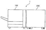
図1は、本実施形態の画像形成システム1の概略構成図である。
図1に示すように、画像形成システム1は、用紙に画像を形成する画像形成手段としての画像形成装置100と、画像形成装置に用紙を給紙する給紙装置200とを備えている。給紙装置200は、画像形成装置100本体の側面に設けられている。
Hereinafter, an embodiment of a sheet feeding device to which the present invention is applied will be described.
FIG. 1 is a schematic configuration diagram of an
As shown in FIG. 1, the
まず、本実施形態の給紙装置を適用可能なプリンター及び、同等の作像機能を有する複写機などの画像形成装置の全体構成及び動作について説明する。
図2は、本実施形態に係る画像形成装置100の概略構成図である。
この画像形成装置100は、イエロー(Y),シアン(C),マゼンタ(M),黒(K)の4色のトナーを用いるフルカラープリンタ及び、同等の作像機能を有するフルカラー複写機である。図2に示すように、装置本体内の上部にそれぞれ各色トナーで作像を行う4つの作像ユニット101Y,101M,101C,101Kを並べて配置している。各作像ユニット101Y,101M,101C,101Kの構成とその動作は実質的に同一であるため、ここでは色を示す符号(Y,M,C,K)を省略して作像ユニットについて説明する。作像ユニット101においては、像担持体としての感光体ドラム102の周囲に、帯電器103,現像装置104,クリーニング装置105等が配置されている。また、感光体ドラム102の上方に位置して、露光手段107が配置されている。
First, the overall configuration and operation of an image forming apparatus such as a printer to which the sheet feeding device of the present embodiment can be applied and a copier having an equivalent image forming function will be described.
FIG. 2 is a schematic configuration diagram of the
The
4つの作像ユニット101Y,101M,101C,101Kの下方には、複数の支持ローラに掛け回された中間転写ベルト108が配置されている。中間転写ベルト108は、支持ローラの一つが駆動手段によって回転駆動されることにより、矢印A方向に走行駆動される。その中間転写ベルト108を挟んで各作像ユニットの感光体ドラム102に対向するように、一次転写手段としての転写ローラ106が配置されている。
Below the four
さて、各作像ユニット101においては、感光体ドラム102が図中反時計回りに回転駆動され、帯電器103によって感光体表面が所定の極性に均一に帯電される。次いでその帯電面に、露光手段107から出射される光変調されたレーザビームが照射され、これによって感光体ドラム102上に静電潜像が形成される。その静電潜像は、現像装置104から付与されるトナーによって現像され、トナー像として可視化される。各作像ユニットで形成されたイエロー,シアン,マゼンタ,黒の各色トナー像は、中間転写ベルト108上に順次重ね合わされて転写される。
In each image forming unit 101, the photoconductor drum 102 is rotated counterclockwise in the drawing, and the photoconductor surface is uniformly charged to a predetermined polarity by the
一方、装置本体の下部には給紙トレイ114a及び114bを有する給紙部114が設けられており、この給紙部114あるいは画像形成装置100に装着される後述する給紙装置200のいずれかから記録媒体として例えば転写紙が給送される。給送された転写紙は、レジストローラ111に向けて矢印Bの如く搬送される。
On the other hand, a
レジストローラ111に突き当てられて一旦停止された転写紙は、中間転写ベルト108上のトナー像とのタイミングを取ってレジストローラ111より送出され、二次転写ローラ109と中間転写ベルト108とが接する二次転写部に送り込まれる。その二次転写ローラ109にトナーの帯電極性と逆極性の電圧が印加され、これによって中間転写ベルト108上の重ねトナー像(フルカラー画像)が転写紙上に転写される。トナー像転写後の転写紙は、搬送ベルト112により定着装置113へ搬送され、定着装置113にて熱と圧力によりトナーが転写紙に定着される。トナー像定着後の転写紙は、矢印Cで示すように機外に排出され、排紙トレイ上に排紙される。
The transfer paper abutted against the
なお、片面印刷で裏面排紙(フェイスダウン排紙)する場合は、用紙反転部115を経て矢印Cで示すように機外に排出することで、用紙の表裏が逆転される。また、両面印刷の場合は、定着後の用紙を両面反転部116を経て再給紙路117よりレジストローラ111へと再給紙し、用紙裏面に中間転写ベルト108よりトナー像が転写される。トナー像転写後の用紙は定着装置113で定着が行われ、片面印刷時と同じように定着装置113から矢印Cで示すように、あるいは用紙反転部115を経て矢印Cで示すように機外に排出され、排紙トレイ上に排紙される。用紙搬送方向を切り替えるための切替爪118,119が適宜配置されている。
In the case of single-sided printing and back-side discharge (face-down discharge), the sheet is discharged to the outside through the
モノクロ印刷の場合は、本例の画像形成装置100では、黒(K)の作像ユニット101Kのみを用いてトナー像を作像し、そのトナー像を中間転写ベルト108を介して転写紙上に転写する。トナー像定着後の用紙の扱いは、フルカラー印刷の場合と同様である。
In the case of monochrome printing, the
なお、装置本体の上面には、各作像ユニットの現像装置104に供給するトナーを収納した各色トナーボトル121をセットするトナーボトルセット部120が設けられている。また、表示部122及び操作パネル123を有する操作部124も装置本体の上面に設けられている。さらに、装置本体の図において右側の側面には、後述する給紙装置(図3参照)からの用紙搬入部Dが設けられている。用紙搬入部Dにおいては、用紙を受け入れる開口125と、用紙を搬送する搬送手段126が設けられている。
It should be noted that a toner
図3は、装置本体の側面に設けられる本実施形態の給紙装置200の概略説明図である。
給紙装置200は、上下2段の給紙トレイ10を備える。各給紙トレイ10は、用紙Pの束を積載する用紙積載部である用紙積載台11を備えている。本実施形態においては、各給紙トレイ10は、最大2500枚程度の用紙を収納可能となっている。各給紙トレイ10の上方には、給紙トレイ10に積載された用紙Pを分離・給紙する給紙ユニット20がそれぞれ配置されている。この給紙ユニット20は、搬送部材である吸着ベルト21及び吸引装置23を備えている。
FIG. 3 is a schematic explanatory diagram of the
The
また、各給紙トレイ10には、用紙積載台11の昇降を制御するために、後述する送風手段によって浮上した浮上用紙を検知する紙面検知センサ31が設けられている。この紙面検知センサ31は、後述する第1検知センサ31aと、第2検知センサ31bとを備えている。
下側の給紙トレイ10に積載された用紙は、下搬送路82を通って、出口ローラ対80によって、画像形成装置100本体へ搬送される。上側の給紙トレイ10に積載された用紙は、上搬送81を通って、出口ローラ対80によって、画像形成装置100本体へ搬送される。
In addition, each
The sheets stacked on the lower
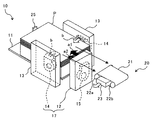
図4は、給紙トレイ10近傍の概略斜視図である。
給紙ユニット20の吸着ベルト21は、2本の張架ローラ22a,22bにより張架されており、ベルトの表面側から裏面側まで貫通する吸引孔が周方向の全域に設けられている。また、吸着ベルト21の内部には、吸引装置23が設けられている。吸引装置23は、空気の流路であるエアダクト通じて空気を吸引する吸引ファンに接続されており、吸引装置23により下方に負圧を発生させることで、吸着ベルト21の下面に用紙Pを吸着させるように作用する。
FIG. 4 is a schematic perspective view of the vicinity of the
The
また、給紙トレイ10には、用紙束Pの上部の用紙に対して空気を吹き付ける送風手段である送風装置17を備える。この送風装置17は、フロント送風装置12とサイド送風装置14とを有している。
フロント送風装置12は、用紙束Pの上部の先端(給紙方向下流側端部)に対して空気を送風するものである。このフロント送風装置12には、用紙束Pを浮上させる方向に空気を案内する浮上ノズル、最上位の浮上用紙とそれ以外の用紙を分離する方向に空気を案内する分離ノズル、及び、浮上ノズルと分離ノズルとにそれぞれ空気を送り込む2つの送風ファン(以下、単に送風ファンという)15が配置されている。この各ノズルのうち、浮上ノズルから図中矢印a1で示す向きに送風される空気を浮上エア、分離ノズルから図中矢印a2で示す向きに送風される空気を分離エアと呼ぶ。浮上エア及び分離エアは、用紙束Pの上部の先端(給紙方向下流側端部)と対向する箇所から吐出され、用紙束Pの上部の先端(給紙方向下流側端部)に吹き付けられる。
Further, the
The
また、サイド送風装置14は、一対のサイドフェンス13に設けられ、用紙束Pの上部の側面に対して図中矢印bで示す向きに空気を送風するものである。このサイド送風装置14には、用紙束Pを捌き、浮上させる方向に空気を案内するサイド浮上ノズルが配置されており、このノズルから図中矢印bで示す向きに送風される空気をサイドエアと呼ぶ。このサイドエアは、各サイドフェンス13の用紙束Pの上部と対向する箇所に設けられた吐出口から吐出され、用紙束P上部の側面に吹き付けられる。フロント送風装置12と、一対のサイドフェンス13の吐出口とから吹き付けられた空気により、用紙束の上部の用紙が浮上する。
また、給紙トレイ10には、用紙積載台11に積載された用紙束Pの後端を揃えるエンドフェンス25を設けている。
The
Further, the
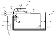
図5は、給紙トレイ10近傍の概略断面図である。
また、吸着ベルト21に対して搬送方向下流側には下流側搬送部材である搬送ローラ対8が配置されており、吸着ベルト21によって搬送されて2つのローラの間に到達した用紙をさらに下流側に向けて搬送する。
また、図5に示すように、用紙の積載方向に紙面検知センサ31が設けられている。上述したように、本実施形態においては、紙面検知センサ31は、第1の検知センサ31aと、第二の検知センサ31bと備えている。この紙面検知センサ31は、反射型光学センサであって、発光素子と受光素子とを備えている。
FIG. 5 is a schematic sectional view near the
A
Further, as shown in FIG. 5, a paper
図6は、紙面検知センサについて説明する図である。
なお、本実施形態の紙面検知センサ31は、上述のとおり2つの紙面検知センサ31a、31bで構成されているが、1つの紙面検知センサを用いた場合の使い方と原理的には変わりがないため、以下の説明では簡略的に1個の紙面検知センサ31aを用いた場合について説明する。
図6に示すように、紙面検知センサ31aの検知エリアXaは、図中Z方向(上下方向)にある程度の幅を有し、複数枚の用紙が検知可能となっている。具体的には、紙面検知センサ31aの発光素子の照射範囲を上記検知エリアXaとし、検知エリアXaで反射した発光素子の光を、レンズで集光して受光素子で受光する構成としている。なお、特許文献1の紙面検知センサでは、この検知エリアXのZ方向の長さを3[mm]に設定している。
FIG. 6 is a diagram illustrating a paper surface detection sensor.
Note that the paper
As shown in FIG. 6, the detection area X a of the sheet sensor 31a has a certain width in the figure Z direction (vertical direction), a plurality of sheets of paper has become detectable. Specifically, the irradiation range of the light-emitting element of the sheet sensor 31a and the detection area X a, the light emitting device reflected by the detection area X a, has a configuration for receiving at condensed to the light receiving element by a lens . In the paper surface detection sensor of
次に、紙面検知センサの検知方法について説明する。
紙面検知センサ31aの閾値β1は、検知エリアXaに規定枚数A(A>1)の浮上用紙が存在するときの用紙検知センサの出力値を閾値β1に設定している。さらに、検知エリアXaにおける用紙一枚における反射率の平均をγ(avg.)とすると、閾値β1は、γ(avg.)×規定枚数A(A>1)で表すことができる。
また、図6に示すように、本実施形態においては、検知エリアXaを浮上領域Eとしている。この浮上領域E内における上位の浮上用紙の複数枚が存在する領域を、給紙ユニット20によって浮上用紙が吸着可能な吸着領域Gとする。この吸着領域Gに位置する用紙は、通常、用紙束Pの上部に位置する2〜3枚である。また、浮上領域Eに存在する浮上用紙より下位の浮上用紙が存在する領域を準浮上領域Fとする。
Next, a detection method of the paper surface detection sensor will be described.
Threshold .beta.1 of the paper detection sensor 31a is set the output value of the paper detection sensor when flying sheet detection area X a in prescribed number A (A> 1) is present in the threshold .beta.1. Further, when the average of the reflectance at a single paper in detection area X a and gamma (avg.), The threshold value β1 may be represented by γ (avg.) × predetermined number A (A> 1).
Further, as shown in FIG. 6, in the present embodiment, the detection area Xa is a floating area E. An area in which a plurality of higher-order floating sheets are present in the floating area E is defined as a suction area G in which the
浮上領域Eの用紙枚数が減少すると、紙面検知センサ31aの出力値α1が閾値β1以下となって用紙積載台11が上昇する。そして、この用紙積載台11の上昇によって、用紙束Pのうち、浮上領域Eの下層の領域である準浮上領域Fに存在する浮上用紙が浮上領域E内に供給される。その結果、浮上領域Eにおける浮上用紙の枚数が多くなり、紙面検知センサ31aの出力値α1が上昇する。本実施形態においては、準浮上領域Fを浮上領域Eの下層5[mm]までとしている。 When the number of sheets in the floating area E decreases, the output value α1 of the sheet surface detection sensor 31a becomes equal to or less than the threshold value β1, and the sheet stacking table 11 rises. Then, as the sheet stacking table 11 rises, the floating sheet existing in the quasi-floating area F, which is a lower layer of the floating area E, of the sheet bundle P is supplied into the floating area E. As a result, the number of floating sheets in the floating area E increases, and the output value α1 of the sheet surface detection sensor 31a increases. In the present embodiment, the quasi-floating area F is limited to 5 [mm] below the floating area E.
次に、本実施形態の給紙制御について説明する。
図7は、本画像形成装置100における制御系の要部構成の一例を示すブロック図である。
図7に示すように、給紙装置200の制御手段としての制御部18には、給紙トレイ10の紙面検知センサ31a、32bが接続されている。また、フロント送風装置12の浮上ノズルと分離ノズルとに空気を送り込む送風ファン15、サイド送風装置14のサイド浮上ノズルに向けて空気を送風する送風ファン14a、及び、吸引装置23の吸引ファン24も接続されている。また、用紙積載台11を昇降させる昇降手段である昇降駆動モータ19も接続されている。
Next, the paper feed control according to the present embodiment will be described.
FIG. 7 is a block diagram illustrating an example of a main configuration of a control system in the
As shown in FIG. 7, sheet control sensors 31 a and 32 b of the
図8は、本実施形態の給紙制御のフローチャートである。
制御部18は、紙面検知センサ31の出力値α1及び出力値α2が閾値β1及び閾値β2以上か否かをチェックする(S1)。閾値β1及び閾値β2以上でない場合(S1のNo)は、昇降駆動モータ19を駆動して、用紙積載台11を上昇させる(S6)。すると、用紙束の上部が、紙面検知センサ31の検知エリアXに入り、紙面検知センサの発光素子から光が、用紙束の上部で反射して、受光素子で受光される。その結果、紙面検知センサ31からの出力値が上昇していく。そして、閾値β1及び閾値β2以上となったら(S1のYes)、昇降駆動モータ19の駆動を停止して、用紙積載台11の上昇を停止する(S3)。これにより、用紙束の上面を給紙位置に位置させることができる。
FIG. 8 is a flowchart of the sheet feeding control according to the present embodiment.
The
次に、制御部18は、給紙動作開始前の場合(S3のYes)は、給紙動作を開始する(S4)。具体的には、吸着ベルト21を停止した状態で、サイド送風装置14(送風ファン14a)と、フロント送風装置12(送風ファン15)の駆動を開始する。これにより、フロント送風装置12の浮上ノズルと分離ノズルから浮上エア及び分離エアが吐出し、用紙束の上部の前端部に空気が吹き付けられる。また、一対のサイドフェンス13のサイドダクトの吐出口から空気が吐出し、用紙束の用紙束の上部の側端部に空気が吹き付けられる。これにより、用紙束上部の用紙が浮上する。
Next, when the sheet feeding operation is not started (Yes in S3), the
また、これと同時に吸引ファン24の駆動を開始し、吸引装置23による吸引を開始することで、浮上した最上位用紙P1が吸着ベルト21に吸着される。そして、吸引装置23の吸引を開始してから所定時間経過後に、吸引ファン24を作動させたままの状態で吸着ベルト21の駆動を開始する。これにより、吸着ベルト21が表面移動し、吸着ベルト21の下面に吸着した最上位用紙P1が搬送方向下流側に向けて搬送され、搬送ローラ対8に到達する。その後、搬送ローラ対8が回転することによって最上位用紙P1が搬送され、画像形成装置100へ搬送される。
また、給紙動作が継続される(S5のNo)場合、紙面検知センサ31の出力値α1及び出力値α2が閾値β1及び閾値β2以上か否か引き続き監視される(S1)。
At the same time, the driving of the
When the paper feeding operation is continued (No in S5), it is continuously monitored whether the output values α1 and α2 of the paper
なお、用紙積載台の上昇動作における上昇量、浮上エアをONにして一定時間経つまでの制御、及び、浮上エアをOFFにするとき制御については後ほど詳述する。 The amount of lifting in the lifting operation of the sheet loading table, the control for turning on the floating air until a certain time passes, and the control for turning off the floating air will be described later in detail.
図9は、ラスト近傍における不給紙発生メカニズムについて説明する図である。図9(a)は、通常の給紙状態を示を示し、図9(b)はラスト近傍の給紙状態を示す。
図9(a)に示すように、用紙積載台11に十分な枚数の用紙束Pが積載された通常の給紙状態から、図7のフローチャートに従い給紙動作が継続されると、用紙積載台11に積載された用紙束Pの枚数が減少して次のような状態となる。すなわち、図9(b)に示すように、用紙積載台11の上昇に伴って浮上エアの送風領域内に用紙積載台11が存在する状態となる(以下、ラスト近傍という)。ラスト近傍になると、用紙束P自体の枚数が少なくなり、また、浮上エアの送風領域内に用紙積載台が存在することで用紙束Pの側面に吹き付けられる浮上エアが少なくなるので、通常の給紙状態と比較して準浮上領域Fに存在する用紙枚数が減少する。
FIG. 9 is a diagram for explaining a non-feeding mechanism in the vicinity of the last. FIG. 9A shows a normal sheet feeding state, and FIG. 9B shows a sheet feeding state near the last.
As shown in FIG. 9A, when the sheet feeding operation is continued according to the flowchart of FIG. 7 from a normal sheet feeding state in which a sufficient number of sheet bundles P are stacked on the sheet stacking table 11, the sheet stacking table The number of sheets P stacked on the
準浮上領域Fに存在する用紙が少ないと、用紙積載台11の1回の上昇で浮上領域Eに供給できる用紙が通常よりも少なくなるので、第1紙面検知センサ31aの出力値α1が閾値β1以下となる頻度が増加する。このため、通常の給紙動作における上昇量では、最終的に用紙積載台の上昇動作が追いつかなくなり、吸着領域Gに用紙が存在しなくなることで、不給紙が発生する。
このようなラスト近傍での上記問題を解決する為に、本実施形態の給紙装置においては、紙面検知センサ31を以下のように構成している。
If the number of sheets existing in the quasi-floating area F is small, the number of sheets that can be supplied to the floating area E by one rise of the sheet stacking table 11 becomes smaller than usual, so that the output value α1 of the first sheet surface detection sensor 31a becomes the threshold value β1. The frequency of: Therefore, with the rising amount in the normal sheet feeding operation, the rising operation of the sheet stacking table eventually cannot catch up, and the sheet does not exist in the suction area G, so that non-feeding occurs.
In order to solve the above problem in the vicinity of the last, in the sheet feeding device of the present embodiment, the sheet
図10は、本実施形態における紙面検知センサの構成を説明する図である。
本実施形態においては、紙面検知センサ31が、浮上領域を監視する第1の紙面検知センサである第1紙面検知センサ31aと、準浮上領域を監視する第2の紙面検知センサである第2紙面検知センサ31bとを有している。本実施形態の制御部18は、これらの紙面検知センサ31a,31bのそれぞれの出力値α1、α2が、閾値β1、β2以下であるか否かによって用紙積載台11の上昇動作および上昇量を制御している。
FIG. 10 is a diagram illustrating the configuration of the paper surface detection sensor according to the present embodiment.
In the present embodiment, the paper
次に、本実施形態における用紙積載台の上昇動作の制御について詳しく説明する。
下記の表1に示すように、紙面検知センサ31a、31bの出力値α1、α2の組み合わせは、4パターン存在する。
Next, the control of the lifting operation of the sheet loading table in the present embodiment will be described in detail.
As shown in Table 1 below, there are four combinations of the output values α1 and α2 of the paper surface detection sensors 31a and 31b.

パターン1は、出力値α1、α2が共にそれぞれの閾値β1、β2以下の場合である。この場合は、浮上領域、及び、準浮上領域の浮上用紙が疎となっており不給紙が生じる可能性が高い。このため、用紙積載台11を、後述する通常の上昇量X1[mm]よりも大きい上昇量X2[mm]で上昇させ、浮上領域に速やかに用紙を供給させる動作を行う。
パターン2は、出力値α1が閾値β1以下であり、出力値α2が閾値β2よりも大きい場合である。この場合は、浮上領域の用紙は疎となっており、準浮上領域には閾値以上の用紙がある。このため、準浮上領域から浮上領域への用紙供給が可能であるので、パターン2の場合には、用紙積載台をパターン1の上昇量X2よりも小さな上昇量X1[mm](X1<X2)で上昇させる。
なお、通常の用紙積載台11を上昇させる制御としては、パターン2の制御が主となる。このため、パターン2の上昇量X1を通常の上昇量X1と言う。
The control of the
パターン3は、出力値α1、α2がそれぞれ閾値β1、β2よりも大きい場合である。この場合、浮上領域、準浮上領域共に閾値以上の用紙枚数がある状態を示すので、用紙積載台11の上昇動作は行わない。
パターン4は、出力値α1が閾値β1よりも大きく、出力値α2が閾値β2以下の場合である。この場合、浮上領域には閾値以上の用紙枚数があるが、準浮上領域の用紙が疎となっている状態を示す。この状態だと、浮上領域が疎となった場合に用紙積載台11を上昇させても、準浮上領域の用紙が少ないので浮上領域に浮上用紙が十分に供給されず、吸着領域への用紙供給が追いつかなくなる可能性がある。このため、パターン4の場合では、用紙積載台11を通常の上昇量X1[mm]より小さい上昇量X3[mm](X3<X1)で上昇させることで、準浮上領域の用紙密度を高める動作を行う。
Pattern 4 is a case where the output value α1 is larger than the threshold value β1 and the output value α2 is equal to or smaller than the threshold value β2. In this case, the floating area has a number of sheets equal to or greater than the threshold value, but the quasi-floating area has sparse sheets. In this state, even if the sheet stacking table 11 is raised when the floating area becomes sparse, the floating sheet is not sufficiently supplied to the floating area because the number of sheets in the quasi-floating area is small, and the paper supply to the suction area is not performed. May not be able to keep up. For this reason, in the case of the pattern 4, an operation of increasing the sheet density in the quasi-floating region by raising the sheet stacking table 11 by an amount of rise X3 [mm] (X3 <X1) smaller than the normal amount of increase X1 [mm]. I do.
このように、パターン4の用紙積載台11の上昇量X3[mm]を通常の上昇量X1[mm]以下の小さい上昇量にすることで、用紙積載台11の上昇量を細やかに制御することができ、次のような不具合を抑制することができる。すなわち、パターン4の場合では、浮上領域の用紙の浮上状態が密となっている。このような場合に、用紙積載台11を通常の上昇量X1[mm]で上昇させると、準浮上領域の浮上用紙が過密となってしまい、この影響を受けて浮上領域の用紙浮上状態も過密となるってしまうおそれがある。浮上領域の用紙浮上状態が過密となると、重送が生じる可能性がある。パターン4の制御のように、用紙積載台11の上昇量を細やかに制御することで、このような浮上領域への影響を最小限にすることができるので、浮上領域の用紙浮上状態が過密になることで生じる重送を抑制することができる。 As described above, by setting the rising amount X3 [mm] of the sheet loading table 11 of the pattern 4 to a small rising amount equal to or smaller than the normal rising amount X1 [mm], the rising amount of the sheet loading table 11 can be finely controlled. And the following problems can be suppressed. That is, in the case of the pattern 4, the floating state of the sheet in the floating area is dense. In such a case, if the paper loading table 11 is raised by the normal lifting amount X1 [mm], the floating paper in the quasi-floating area becomes overcrowded, and under the influence, the floating state of the paper in the floating area is also overcrowded. There is a possibility that it becomes. If the floating state of the paper in the floating area becomes too dense, double feeding may occur. By finely controlling the amount of rise of the sheet loading table 11 as in the control of the pattern 4, the influence on the floating area can be minimized. It is possible to suppress the double feed caused by the occurrence.
本実施形態の給紙装置における通常の用紙積載台11の制御としては、パターン2とパターン3の制御が主となる。そして、ラスト近傍などで浮上領域は閾値以上の用紙枚数があるが準浮上領域の用紙が疎となっている状態になると、パターン4の制御、すなわち、用紙積載台11を通常の上昇量X1[mm]よりも小さい上昇量X3[mm]で上昇させる。このため、準浮上領域の浮上用紙が疎となった場合に生じる、浮上領域の過疎化による不給紙を抑制することができる。
また、パターン4の制御でも用紙浮上が追いつかない場合には、浮上領域、及び、準浮上領域の浮上用紙が疎となる。このとき、本実施形態においては、パターン1の制御を行うことで、ラスト近傍などで生じる浮上領域の過疎化による不給紙を2段階で防ぐことができる。
Control of the
In addition, if the paper floating cannot catch up with the control of the pattern 4, the floating paper in the floating area and the quasi-floating area is sparse. At this time, in the present embodiment, by performing the control of the
また、図11に示すように、本実施形態の給紙装置では、2つの紙面検知センサ31a、31bを次のように配置している。すなわち、紙面検知センサ31を、図中矢印Hで示すように吸着ベルト21の最下面から12[mm]下の位置に配置している。また、紙面検知センサ31を、図中矢印Iで示すように紙面検知センサ31の6[mm]下の位置に配置している。これにより、浮上領域Eおよび準浮上領域Fの用紙の浮上状態を監視している。
Further, as shown in FIG. 11, in the paper feeder of the present embodiment, two paper surface detection sensors 31a and 31b are arranged as follows. That is, the paper
さらにまた、用紙積載台11の動作条件を浮上エアの状態と紐付けて切り替えを行ってもよい。本実施形態の給紙装置では、用紙積載台の動作条件によって浮上エアのON・OFFを切り替えている。
下記の表2は、用紙積載台11の動作条件を浮上エアの状態と紐付けて切り替えを行った場合の給紙装置の制御を示している。表2(a)は浮上エアがONになった状態、表2の(b)は表2(a)の状態からT[s]経過した状態、表2の(c)は、表2の(b)の状態から浮上エアをOFFにした状態の各パターン1〜4における制御を示している。
Furthermore, the operating condition of the paper loading table 11 may be switched in association with the state of the floating air. In the sheet feeding device of the present embodiment, ON / OFF of the floating air is switched according to the operation condition of the sheet loading table.
Table 2 below shows the control of the sheet feeding device when the operating condition of the sheet loading table 11 is switched in association with the state of the floating air. Table 2 (a) shows a state in which the levitation air is ON, Table 2 (b) shows a state in which T [s] has elapsed from the state in Table 2 (a), and Table 2 (c) shows a state in Table 2 ( The control in each of the
浮上エアをOFF状態にするとき、表2(c)のパターン2及びパターン3に示すように、第2紙面検知センサ31bの出力値α2が閾値β2よりも大きくなった時点で用紙積載台の上昇を停止する。例えば、用紙積載台を上昇させて第1紙面検知センサ31aの出力値α1が閾値β1以上となる位置まで用紙束Pを上昇させると、次に浮上エアをON状態にして用紙を浮上させた場合に、浮上領域の用紙が過浮上となる可能性がある。このため、表2(c)に示すように、第2紙面検知センサ31bの出力値α2が閾値β2よりも大きくなった時点で用紙積載台の上昇を停止するよう制御することで、浮上エアをONして用紙浮上させた場合に生じる浮上用紙の過浮上を防止することができる。
When the floating air is turned off, as shown in the
また、浮上エアをON状態にしてからT[s]経過するまでは、用紙浮上状態が安定しない。このため、表2(a)に示すように、浮上エアをOFF状態した時と同じ条件マトリックスを適用する。なお、本実施形態においては、浮上エアをON状態にしてからの所定時間T[s]を5秒経過するまでとしている。
また、本実施形態における各パターンの上昇量はX1=1[mm]、X2=3[mm]、X3=0.5[mm]とした。
Further, the sheet floating state is not stabilized until T [s] elapses after the floating air is turned on. For this reason, as shown in Table 2 (a), the same condition matrix as when the floating air is turned off is applied. In the present embodiment, the predetermined time T [s] from when the levitation air is turned on is set to be 5 seconds.
In addition, the rising amount of each pattern in the present embodiment is set to X1 = 1 [mm], X2 = 3 [mm], and X3 = 0.5 [mm].
以上に説明したものは一例であり、次の態様毎に特有の効果を奏する。
(態様A)
用紙束を積載する用紙積載台11等の用紙積載部と、該用紙積載部に積載した用紙束にエアを吹き付けて、前記用紙束の上部の複数枚の用紙を浮上させる送風装置17等の送風手段と、前記用紙積載部を昇降させる昇降駆動モータ19等の昇降手段と、前記送風手段によって浮上した浮上用紙を検知する紙面検知センサ31等の反射型光学センサと、前記反射型光学センサの出力値に基づいて、前記昇降手段を制御する制御部18等の制御手段とを備えた給紙装置において、前記反射型光学センサが第1紙面検知センサ31a等の第1の反射型光学センサと、該第1の反射型光学センサによって検知される前記浮上用紙の下位に位置する浮上用紙を検知する第2紙面検知センサ31b等の第2の反射型光学センサとを備え、前記制御手段が、前記第1及び第2の反射型光学センサの出力値α1、α2等の出力値の組み合わせに基づいて、前記昇降手段を制御することを特徴とする。
What has been described above is merely an example, and a specific effect is obtained for each of the following aspects.
(Aspect A)
A sheet stacking section such as a sheet stacking table 11 for stacking sheet stacks, and an
従来の反射型光学センサの検知エリアを浮上領域Eとし、浮上領域Eに存在する浮上用紙より下位の浮上用紙が存在する領域を準浮上領域Fとした場合、浮上領域Eの用紙枚数が減少すると、紙面検知センサの出力値αが閾値β以下となって用紙積載台が上昇する。この用紙積載台の上昇によって、用紙束Pのうち、浮上領域Eの下層の領域である準浮上領域Fに存在する浮上用紙が浮上領域E内に供給される。その結果、浮上領域Eにおける浮上用紙の枚数が多くなることで、紙面検知センサの出力値αが上昇し、この出力値αの目標値である閾値βに近づけることができる。 If the detection area of the conventional reflection type optical sensor is a floating area E, and the area where the floating paper lower than the floating paper existing in the floating area E exists is the quasi-floating area F, if the number of sheets in the floating area E decreases, Then, the output value α of the sheet surface detection sensor becomes equal to or less than the threshold value β, and the sheet stacking table rises. By the elevation of the sheet stacking table, the floating sheet existing in the quasi-floating area F, which is a lower layer of the floating area E, of the sheet bundle P is supplied into the floating area E. As a result, the output value α of the paper surface detection sensor increases due to the increase in the number of floating sheets in the floating area E, and the output value α can approach the threshold value β which is the target value of the output value α.
しかし、例えば、用紙積載台に積載された用紙束Pの枚数が減少し、用紙積載台の上昇に伴って浮上エアの送風領域内に用紙積載台が存在する状態となる(以下、ラスト近傍という)と、次のような不具合が生じる。すなわち、ラスト近傍になると、用紙束P自体の枚数が少なくなり、また、浮上エアの送風領域内に用紙積載台が存在することで用紙束Pの側面に吹き付けられる浮上エアが少なくなるので、通常の給紙状態と比較して準浮上領域Fに存在する用紙枚数が減少する。準浮上領域Fに存在する用紙枚数が減少すると、用紙積載台の1回の上昇で浮上領域に供給できる用紙が通常よりも少なくなるので、紙面検知センサの出力値αが閾値β以下となる頻度が増加する。このため、通常の給紙動作における上昇量では、最終的に用紙積載台の上昇動作が追いつかなくなり、吸着領域に用紙が存在しなくなることで、不給紙が発生するおそれがある。 However, for example, the number of the sheet bundles P stacked on the sheet stacking table decreases, and the sheet stacking table is present in the air blowing area of the floating air with the rise of the sheet stacking table (hereinafter, referred to as near the last). ) And the following problems occur. That is, in the vicinity of the last, the number of sheets of the sheet bundle P itself decreases, and the floating air blown to the side surface of the sheet bundle P decreases due to the presence of the sheet loading table in the air blowing area of the floating air. The number of sheets existing in the quasi-floating area F is reduced as compared with the sheet feeding state of FIG. When the number of sheets existing in the quasi-floating area F decreases, the number of sheets that can be supplied to the floating area by one rise of the sheet loading table becomes smaller than usual, so that the output value α of the paper surface detection sensor becomes equal to or less than the threshold β. Increase. For this reason, with the rising amount in the normal sheet feeding operation, the rising operation of the sheet stacking table cannot finally catch up, and there is no sheet in the suction area, so that there is a possibility that non-feeding may occur.
本態様においては、実施形態について説明したように、反射型光学センサとして、浮上領域E内の浮上用紙を検知する第1紙面検知センサ31aと、準浮上領域F内の浮上用紙を検知する第2紙面検知センサ31bとを備えているので、次のことが可能となる。すなわち、浮上領域Eにおける浮上用紙の密度と、準浮上領域Fにおける浮上用紙の密度とを検出することが可能となる。このため、浮上領域Eだけでなく準浮上領域Fにおける用紙積載部の上昇の必要性を検知することが可能となる。また、本態様においては、第1及び第2の紙面検知センサ31a、31bの出力値α1、α2の組み合わせに基づいて、用紙積載台11の上昇量を変化させるよう制御している。したがって、準浮上領域F内の浮上用紙の密度が規定値となるように用紙積載台11の上昇動作を制御することが可能となるので、準浮上領域F内の浮上用紙が疎となった場合に生じる浮上領域Eの過疎化を防ぐことが可能となる。これにより、浮上領域Eの過疎化による不給紙を抑制することができる。 In this aspect, as described in the embodiment, as the reflection type optical sensor, the first paper surface detection sensor 31a that detects the floating paper in the floating region E and the second paper surface sensor that detects the floating paper in the quasi-floating region F The provision of the paper surface detection sensor 31b enables the following. That is, it is possible to detect the density of the floating paper in the floating area E and the density of the floating paper in the quasi-floating area F. For this reason, it is possible to detect the necessity of raising the sheet stacking section not only in the floating area E but also in the quasi-floating area F. Further, in the present embodiment, control is performed so as to change the rising amount of the paper stacking table 11 based on a combination of the output values α1 and α2 of the first and second paper surface detection sensors 31a and 31b. Therefore, it is possible to control the raising operation of the sheet stacking table 11 so that the density of the floating paper in the quasi-floating area F becomes a specified value. In the floating region E can be prevented. Thereby, non-feeding due to depopulation of the flying area E can be suppressed.
(態様B)
態様Aの給紙装置おいて、制御部18等の前記制御手段が、第1紙面検知センサ31a、第2紙面検知センサ31b等の前記第1及び第2の反射型光学センサの出力値α1、α2等の出力値の組み合わせに基づいて、昇降駆動モータ19等の前記昇降手段の上昇動作の有無、及び、用紙積載台11等の前記用紙載置部の上昇量を変化させるよう制御する。
(Aspect B)
In the sheet feeding device according to the aspect A, the control unit such as the
(態様C)
態様A又はBに記載の給紙装置において、第2紙面検知センサ31b等の前記第2反射型光学センサを、第1紙面検知センサ31a等の前記第1前記反射型光学センサから用紙積載高さ方向に所定量だけずれた位置に配置する。
(Aspect C)
In the sheet feeding device according to the aspect A or B, the second reflection type optical sensor such as the second sheet surface detection sensor 31b is moved from the first reflection type optical sensor such as the first sheet surface detection sensor 31a to the sheet stacking height. It is arranged at a position shifted by a predetermined amount in the direction.
(態様D)
態様A〜Cいずれか一の現像装置において、第1紙面検知センサ31a等の前記第1の反射型光学センサ、及び、第2紙面検知センサ31b等の前記第2の反射型光学センサの出力値α1、α2等の出力値が閾値以下となった場合の前記用紙載置部の上昇量X2等の上昇量を、第1紙面検知センサ31a等の前記第1の反射型光学センサの出力値α1等の出力値のみが閾値β1等の閾値以下となった場合の前記用紙載置部の通常の上昇量X1等の上昇量よりも大きくすることを特徴とする。
(Aspect D)
In the developing device according to any one of Aspects A to C, output values of the first reflective optical sensor such as the first paper surface sensor 31a and the second reflective optical sensor such as the second paper surface sensor 31b are provided. When the output values such as α1 and α2 are equal to or less than the threshold value, the amount of rise such as the amount of rise X2 of the sheet placement unit is determined by the output value α1 of the first reflection type optical sensor such as the first sheet surface detection sensor 31a. And the like, when only the output value of the sheet mounting portion becomes equal to or less than the threshold value such as the threshold value β1, is set to be larger than the normal rising amount X1 or the like of the paper placing portion.
出力値α1、α2が共にそれぞれの閾値β1、β2よりも小さい場合、浮上領域、及び、準浮上領域の浮上用紙が疎となっており不給紙が生じる可能性が高い。
本態様においては、実施形態について説明したように、用紙積載台11を通常の上昇量X1[mm]よりも大きい上昇量X3[mm]で上昇させることで、浮上領域に速やかに用紙を供給させる動作を行うことが可能となる。
When both the output values α1 and α2 are smaller than the respective threshold values β1 and β2, the floating sheets in the floating area and the quasi-floating area are sparse, and there is a high possibility that non-feeding will occur.
In the present embodiment, as described in the embodiment, the sheet stacking table 11 is raised by the lift amount X3 [mm] larger than the normal lift amount X1 [mm], so that the sheet is promptly supplied to the floating area. The operation can be performed.
(態様E)
態様A〜Dいずれか一の給紙装置において、第2紙面検知センサ31b等の前記第2の反射型光学センサの出力値α2等の出力値のみが閾値β2等の閾値以下となった場合の前記用紙載置部の上昇量X3等の上昇量を、第1紙面検知センサ31a等の前記第1の反射型光学センサの出力値α1等の出力値のみが閾値β1等の閾値以下となった場合の前記用紙載置部の通常の上昇量X1等の上昇量よりも小さくすることを特徴とする。
(Aspect E)
In the sheet feeding device according to any one of modes A to D, a case where only the output value such as the output value α2 of the second reflection type optical sensor such as the second paper surface detection sensor 31b becomes equal to or less than the threshold value such as the threshold value β2. Only the output value such as the output value α1 of the first reflection type optical sensor such as the first paper surface detection sensor 31a is equal to or less than the threshold value such as the threshold value β1. In this case, the rising amount such as the normal rising amount X1 of the sheet placing portion is set to be smaller than the rising amount.
第2紙面検知センサ31bの出力値α2のみが閾値β2以下となった場合、浮上領域の用紙の浮上状態は密となっている。このような場合に、用紙積載台11を通常の上昇量X1[mm]で上昇させると、準浮上領域の浮上用紙が過密となってしまい、この影響を受けて浮上領域の浮上用紙も過密となるってしまうおそれがある。浮上領域の浮上用紙が過密となると、重送が生じる可能性がある。
本態様においては、実施形態について説明したように、用紙積載台11の上昇量X3[mm]を通常の上昇量X1[mm]よりも小さい上昇量としているので、用紙積載台11の上昇量を細やかに制御することが可能となる。これにより、上述したような浮上領域への影響を最小限にすることができ、浮上領域の用紙浮上状態が過密になることで生じる重送を抑制することができる。
When only the output value α2 of the second sheet surface detection sensor 31b is equal to or less than the threshold value β2, the floating state of the sheet in the floating area is dense. In such a case, if the paper stacking table 11 is raised by the normal lifting amount X1 [mm], the floating paper in the quasi-floating area becomes overcrowded. There is a possibility that it will become. If the floating paper in the floating area becomes overcrowded, double feeding may occur.
In this aspect, as described in the embodiment, the rising amount X3 [mm] of the sheet loading table 11 is set to be smaller than the normal rising amount X1 [mm]. Fine control is possible. As a result, the influence on the floating area as described above can be minimized, and double feed caused by the paper floating state of the floating area becoming too dense can be suppressed.
(態様F)
態様A〜Eいずれか一の給紙装置において、第2紙面検知センサ31b等の前記第2の反射型光学センサの出力値α2等の出力値の閾値β2等の閾値を、第1紙面検知センサ31a等の前記第1の反射型光学センサの出力値α1等の出力値の閾値β1等の閾値よりも大きくする。
(Aspect F)
In the sheet feeding device according to any one of Aspects A to E, the threshold value such as the output value threshold value β2 such as the output value α2 of the second reflection type optical sensor such as the second paper surface detection sensor 31b is set to the first paper surface detection sensor. The threshold value of the output value such as the output value α1 of the first reflection type optical sensor such as 31a is made larger than the threshold value such as the threshold value β1.
(態様G)
態様A〜Fいずれか一の給紙装置において、昇降駆動モータ19等の前記昇降手段による上昇動作の有無、及び、用紙積載台11等の前記用紙載置部の上昇量X1、X2、X3等の上昇量の変化が送風装置17等の前記送風手段の作動状態によって切り替わることを特徴とする。
(Aspect G)
In the sheet feeding device according to any one of the modes A to F, the presence / absence of a lifting operation by the lifting / lowering means such as the lifting / lowering
例えば、浮上エアをOFF状態にするとき、用紙積載台を上昇させて第1紙面検知センサ31aの出力値α1が閾値β1以上となる位置まで用紙束Pを上昇させると、次のような不具合が生じる可能性がある。すなわち、次に浮上エアをON状態にして用紙を浮上させた場合に、浮上領域の用紙が過浮上となる可能性がある。
本態様においては、実施形態について説明したように、第2紙面検知センサ31bの出力値α2が閾値β2より大きくなった時点で用紙積載台の上昇を停止するよう制御することが可能となるので、浮上エアをONして用紙浮上させた場合に生じる浮上用紙の過浮上を防止することができる。
For example, when the floating air is turned off, if the sheet stacking table is raised to raise the sheet bundle P to a position where the output value α1 of the first sheet surface detection sensor 31a is equal to or more than the threshold value β1, the following problem occurs. Can occur. That is, the next time the floating air is turned on to float the paper, the paper in the floating area may be over-floated.
In this aspect, as described in the embodiment, it is possible to perform control so as to stop the elevation of the sheet loading table when the output value α2 of the second sheet surface detection sensor 31b becomes larger than the threshold value β2. Excessive floating of the floating sheet which occurs when the sheet is floated by turning on the floating air can be prevented.
(態様H)
用紙に画像を形成する画像形成手段と、画像形成手段へ向けて用紙を給紙する給紙手段とを備えた画像形成装置において、前記給紙手段として、態様A〜Gいずれか一の給紙装置を用いたことを特徴とする。
かかる構成を備えることで、給紙不良を抑制し、用紙ジャムの発生を抑制することができる。
(Aspect H)
In an image forming apparatus including an image forming unit that forms an image on a sheet and a sheet feeding unit that feeds the sheet toward the image forming unit, the sheet feeding unit according to any one of modes A to G is used as the sheet feeding unit. It is characterized by using the device.
By providing such a configuration, it is possible to suppress a feeding failure and to suppress the occurrence of a paper jam.
(態様I)
少なくとも用紙に画像を形成する画像形成手段を備えた画像形成装置100等の画像形成装置と、画像形成装置へ向けて用紙を給紙する給紙装置200等の給紙装置とを備えた画像形成システム1等の画像形成システムにおいて、前記給紙装置として、態様A〜Gいずれか一の給紙装置を用いたことを特徴とする。
かかる構成を備えることで、給紙不良を抑制し、用紙ジャムの発生を抑制することができる画像形成システムを提供することができる。
(Aspect I)
Image forming apparatus including image forming apparatus such as
By providing such a configuration, it is possible to provide an image forming system capable of suppressing a paper feeding defect and suppressing a paper jam.
1 画像形成システム
10 給紙トレイ
11 用紙積載台
17 送風装置
18 制御部
19 昇降駆動モータ
20 給紙ユニット
31a 第1紙面検知センサ
31b 第2紙面検知センサ
100 画像形成装置
101 作像ユニット
102 感光体ドラム
103 帯電器
104 現像装置
105 クリーニング装置
107 露光手段
108 中間転写ベルト
109 二次転写ローラ
111 レジストローラ
113 定着装置
200 給紙装置
E 浮上領域
F 準浮上領域
G 吸着領域
P 用紙束
X 用紙積載台の上昇量
α1 第1紙面検知センサの出力値
α2 第2紙面検知センサの出力値
β1 第1紙面検知センサの閾値
β2 第2紙面検知センサの閾値
DESCRIPTION OF
Claims (9)
Priority Applications (2)
| Application Number | Priority Date | Filing Date | Title |
|---|---|---|---|
| JP2015238880A JP6624506B2 (en) | 2015-12-07 | 2015-12-07 | Paper feeder, image forming apparatus, and image forming system |
| US15/364,805 US9926157B2 (en) | 2015-12-07 | 2016-11-30 | Sheet feeder, image forming apparatus incorporating the sheet feeder, and image forming system incorporating the sheet feeder |
Applications Claiming Priority (1)
| Application Number | Priority Date | Filing Date | Title |
|---|---|---|---|
| JP2015238880A JP6624506B2 (en) | 2015-12-07 | 2015-12-07 | Paper feeder, image forming apparatus, and image forming system |
Publications (3)
| Publication Number | Publication Date |
|---|---|
| JP2017105563A JP2017105563A (en) | 2017-06-15 |
| JP2017105563A5 JP2017105563A5 (en) | 2018-12-27 |
| JP6624506B2 true JP6624506B2 (en) | 2019-12-25 |
Family
ID=58798781
Family Applications (1)
| Application Number | Title | Priority Date | Filing Date |
|---|---|---|---|
| JP2015238880A Active JP6624506B2 (en) | 2015-12-07 | 2015-12-07 | Paper feeder, image forming apparatus, and image forming system |
Country Status (2)
| Country | Link |
|---|---|
| US (1) | US9926157B2 (en) |
| JP (1) | JP6624506B2 (en) |
Families Citing this family (13)
| Publication number | Priority date | Publication date | Assignee | Title |
|---|---|---|---|---|
| JP7091028B2 (en) * | 2017-06-29 | 2022-06-27 | 理想科学工業株式会社 | Paper feed table lift control method for air feeders and air feeders |
| US10662009B2 (en) | 2017-11-22 | 2020-05-26 | Ricoh Company, Ltd. | Sheet feeding device, image forming apparatus, and image forming system |
| US10787329B2 (en) | 2017-12-28 | 2020-09-29 | Ricoh Company, Ltd. | Sheet feeding device, image forming apparatus, image forming system, and sheet processing apparatus |
| JP7129026B2 (en) * | 2017-12-28 | 2022-09-01 | 株式会社リコー | Sheet feeding device, image forming device, image forming system, and sheet processing device |
| SE543543C2 (en) * | 2019-03-20 | 2021-03-23 | Plockmatic Int Ab | Sheet feeding device with dynamic float adjustment |
| US11634291B2 (en) | 2019-09-27 | 2023-04-25 | Ricoh Company, Ltd. | Belt conveyance device, sheet feeding device, image forming apparatus, and image forming system |
| JP2021098592A (en) * | 2019-12-23 | 2021-07-01 | キヤノンファインテックニスカ株式会社 | Sheet feeding device |
| JP2021107282A (en) * | 2019-12-27 | 2021-07-29 | キヤノンファインテックニスカ株式会社 | Paper feeder |
| US11479424B2 (en) * | 2020-01-27 | 2022-10-25 | Fujifilm Business Innovation Corp. | Sheet transport device and non-transitory computer readable medium |
| JP7465114B2 (en) * | 2020-02-26 | 2024-04-10 | 理想科学工業株式会社 | Media Supply Device |
| US11518633B2 (en) * | 2020-03-11 | 2022-12-06 | Riso Kagaku Corporation | Sheet feed device |
| JP7417195B2 (en) | 2020-03-19 | 2024-01-18 | 株式会社リコー | Feeding device and image forming device |
| JP7440342B2 (en) | 2020-05-22 | 2024-02-28 | 理想科学工業株式会社 | sheet feeding device |
Family Cites Families (24)
| Publication number | Priority date | Publication date | Assignee | Title |
|---|---|---|---|---|
| US7267337B2 (en) * | 2003-11-25 | 2007-09-11 | Xerox Corporation | Sheet curl correction method and feeder apparatus |
| JP4739084B2 (en) * | 2006-04-03 | 2011-08-03 | キヤノン株式会社 | Sheet feeding apparatus and image forming apparatus |
| JP4739110B2 (en) * | 2006-05-12 | 2011-08-03 | キヤノン株式会社 | Image forming apparatus |
| JP4732297B2 (en) * | 2006-10-13 | 2011-07-27 | キヤノン株式会社 | Sheet feeding apparatus and image forming apparatus |
| JP4750685B2 (en) * | 2006-12-19 | 2011-08-17 | キヤノン株式会社 | Sheet feeding apparatus and image forming apparatus |
| US8336873B2 (en) | 2007-09-07 | 2012-12-25 | Ricoh Company, Limited | Media feeding apparatus and image forming apparatus |
| JP5298804B2 (en) * | 2008-11-20 | 2013-09-25 | コニカミノルタ株式会社 | Paper feeding device and image forming apparatus |
| JP5854766B2 (en) * | 2011-11-01 | 2016-02-09 | キヤノン株式会社 | Sheet feeding apparatus and image forming apparatus |
| JP2014148379A (en) | 2013-01-31 | 2014-08-21 | Ricoh Co Ltd | Recording medium supply device and image formation device |
| JP2014152023A (en) | 2013-02-12 | 2014-08-25 | Ricoh Co Ltd | Paper feeder and image forming device |
| JP2014156310A (en) | 2013-02-15 | 2014-08-28 | Ricoh Co Ltd | Paper feeding device and image forming device |
| JP6051966B2 (en) | 2013-03-08 | 2016-12-27 | 株式会社リコー | Paper feeding device and image forming apparatus |
| JP6051965B2 (en) | 2013-03-08 | 2016-12-27 | 株式会社リコー | Paper feeding device and image forming apparatus |
| JP5786881B2 (en) * | 2013-03-18 | 2015-09-30 | コニカミノルタ株式会社 | Sheet supply apparatus and image forming apparatus |
| JP6098353B2 (en) | 2013-05-16 | 2017-03-22 | 株式会社リコー | Paper feeding device and image forming apparatus |
| JP2015003827A (en) | 2013-05-21 | 2015-01-08 | 株式会社リコー | Sheet separation transport device, and image forming apparatus |
| JP6160300B2 (en) | 2013-06-27 | 2017-07-12 | 株式会社リコー | Paper feeding device and image forming apparatus |
| JP5799986B2 (en) * | 2013-07-17 | 2015-10-28 | コニカミノルタ株式会社 | Sheet supply apparatus and image forming apparatus |
| JP6347066B2 (en) * | 2013-07-24 | 2018-06-27 | コニカミノルタ株式会社 | Sheet supply apparatus and image forming apparatus |
| JP2015110464A (en) | 2013-12-06 | 2015-06-18 | 株式会社リコー | Sheet feeder and image formation apparatus |
| JP6443724B2 (en) * | 2013-12-16 | 2018-12-26 | 株式会社リコー | Paper feeding device, image forming apparatus, and image forming system |
| JP2015164874A (en) | 2014-02-07 | 2015-09-17 | 株式会社リコー | Paper feeder and image forming device provided with the same |
| JP6145793B2 (en) * | 2014-09-04 | 2017-06-14 | コニカミノルタ株式会社 | Sheet supply apparatus and image forming apparatus |
| JP6642854B2 (en) * | 2015-12-16 | 2020-02-12 | 株式会社リコー | Sheet material supply device |
-
2015
- 2015-12-07 JP JP2015238880A patent/JP6624506B2/en active Active
-
2016
- 2016-11-30 US US15/364,805 patent/US9926157B2/en active Active
Also Published As
| Publication number | Publication date |
|---|---|
| US20170160689A1 (en) | 2017-06-08 |
| US9926157B2 (en) | 2018-03-27 |
| JP2017105563A (en) | 2017-06-15 |
Similar Documents
| Publication | Publication Date | Title |
|---|---|---|
| JP6624506B2 (en) | Paper feeder, image forming apparatus, and image forming system | |
| JP6443724B2 (en) | Paper feeding device, image forming apparatus, and image forming system | |
| JP6413604B2 (en) | Sheet separating apparatus, sheet feeding apparatus, and image forming apparatus | |
| JP4732297B2 (en) | Sheet feeding apparatus and image forming apparatus | |
| US8002265B2 (en) | Sheet supply apparatus, sheet supply unit and image forming apparatus | |
| JP7129026B2 (en) | Sheet feeding device, image forming device, image forming system, and sheet processing device | |
| US10787329B2 (en) | Sheet feeding device, image forming apparatus, image forming system, and sheet processing apparatus | |
| US10518992B2 (en) | Sheet feeding device, image forming apparatus incorporating the sheet feeding device, and image forming system incorporating the sheet feeding device | |
| JP2017210370A (en) | Sheet feeding device, image formation apparatus and image formation system | |
| JP2014169182A (en) | Paper feeder and image forming apparatus | |
| JP6186966B2 (en) | Paper feeding device and image forming system | |
| JP7155724B2 (en) | Sheet feeding device, image forming device and image forming system | |
| JP2010163254A (en) | Paper feeding device | |
| JP6774644B2 (en) | Sheet feeding device and image forming device | |
| JP3441525B2 (en) | Sheet feeder and image forming apparatus provided with the same | |
| US11111094B2 (en) | Sheet feeding device and image forming system incorporating the sheet feeding device | |
| JP6972499B2 (en) | Feeding device and image forming device | |
| JP6274157B2 (en) | Paper feeding device, image forming apparatus, and image forming system | |
| JP2010215350A (en) | Paper feeder, paper feed unit, and image forming system | |
| JP2017114633A (en) | Sheet feeding device, image forming apparatus and image forming system | |
| JP7275932B2 (en) | Paper feeder, image forming system, and position inspection method | |
| JP7336067B2 (en) | Sheet conveying device and image forming device | |
| JP6972498B2 (en) | Feeding device and image forming device | |
| JP2005132514A (en) | Paper feeder and image forming device equipped with the paper feeder | |
| JP2023091348A (en) | Feeding device and image forming device |
Legal Events
| Date | Code | Title | Description |
|---|---|---|---|
| A521 | Request for written amendment filed |
Free format text: JAPANESE INTERMEDIATE CODE: A523 Effective date: 20181115 |
|
| A621 | Written request for application examination |
Free format text: JAPANESE INTERMEDIATE CODE: A621 Effective date: 20181116 |
|
| A977 | Report on retrieval |
Free format text: JAPANESE INTERMEDIATE CODE: A971007 Effective date: 20190814 |
|
| A131 | Notification of reasons for refusal |
Free format text: JAPANESE INTERMEDIATE CODE: A131 Effective date: 20190823 |
|
| A521 | Request for written amendment filed |
Free format text: JAPANESE INTERMEDIATE CODE: A523 Effective date: 20191021 |
|
| TRDD | Decision of grant or rejection written | ||
| A01 | Written decision to grant a patent or to grant a registration (utility model) |
Free format text: JAPANESE INTERMEDIATE CODE: A01 Effective date: 20191101 |
|
| A61 | First payment of annual fees (during grant procedure) |
Free format text: JAPANESE INTERMEDIATE CODE: A61 Effective date: 20191114 |
|
| R151 | Written notification of patent or utility model registration |
Ref document number: 6624506 Country of ref document: JP Free format text: JAPANESE INTERMEDIATE CODE: R151 |