JP5854766B2 - Sheet feeding apparatus and image forming apparatus - Google Patents
Sheet feeding apparatus and image forming apparatus Download PDFInfo
- Publication number
- JP5854766B2 JP5854766B2 JP2011240474A JP2011240474A JP5854766B2 JP 5854766 B2 JP5854766 B2 JP 5854766B2 JP 2011240474 A JP2011240474 A JP 2011240474A JP 2011240474 A JP2011240474 A JP 2011240474A JP 5854766 B2 JP5854766 B2 JP 5854766B2
- Authority
- JP
- Japan
- Prior art keywords
- sheet
- sheet feeding
- rear end
- gap
- tray
- Prior art date
- Legal status (The legal status is an assumption and is not a legal conclusion. Google has not performed a legal analysis and makes no representation as to the accuracy of the status listed.)
- Active
Links
Images


Classifications
-
- B—PERFORMING OPERATIONS; TRANSPORTING
- B65—CONVEYING; PACKING; STORING; HANDLING THIN OR FILAMENTARY MATERIAL
- B65H—HANDLING THIN OR FILAMENTARY MATERIAL, e.g. SHEETS, WEBS, CABLES
- B65H1/00—Supports or magazines for piles from which articles are to be separated
- B65H1/08—Supports or magazines for piles from which articles are to be separated with means for advancing the articles to present the articles to the separating device
- B65H1/14—Supports or magazines for piles from which articles are to be separated with means for advancing the articles to present the articles to the separating device comprising positively-acting mechanical devices
-
- B—PERFORMING OPERATIONS; TRANSPORTING
- B65—CONVEYING; PACKING; STORING; HANDLING THIN OR FILAMENTARY MATERIAL
- B65H—HANDLING THIN OR FILAMENTARY MATERIAL, e.g. SHEETS, WEBS, CABLES
- B65H3/00—Separating articles from piles
- B65H3/08—Separating articles from piles using pneumatic force
- B65H3/0808—Suction grippers
- B65H3/0816—Suction grippers separating from the top of pile
-
- B—PERFORMING OPERATIONS; TRANSPORTING
- B65—CONVEYING; PACKING; STORING; HANDLING THIN OR FILAMENTARY MATERIAL
- B65H—HANDLING THIN OR FILAMENTARY MATERIAL, e.g. SHEETS, WEBS, CABLES
- B65H3/00—Separating articles from piles
- B65H3/46—Supplementary devices or measures to assist separation or prevent double feed
- B65H3/48—Air blast acting on edges of, or under, articles
-
- B—PERFORMING OPERATIONS; TRANSPORTING
- B65—CONVEYING; PACKING; STORING; HANDLING THIN OR FILAMENTARY MATERIAL
- B65H—HANDLING THIN OR FILAMENTARY MATERIAL, e.g. SHEETS, WEBS, CABLES
- B65H3/00—Separating articles from piles
- B65H3/46—Supplementary devices or measures to assist separation or prevent double feed
- B65H3/54—Pressing or holding devices
-
- B—PERFORMING OPERATIONS; TRANSPORTING
- B65—CONVEYING; PACKING; STORING; HANDLING THIN OR FILAMENTARY MATERIAL
- B65H—HANDLING THIN OR FILAMENTARY MATERIAL, e.g. SHEETS, WEBS, CABLES
- B65H7/00—Controlling article feeding, separating, pile-advancing, or associated apparatus, to take account of incorrect feeding, absence of articles, or presence of faulty articles
- B65H7/02—Controlling article feeding, separating, pile-advancing, or associated apparatus, to take account of incorrect feeding, absence of articles, or presence of faulty articles by feelers or detectors
- B65H7/04—Controlling article feeding, separating, pile-advancing, or associated apparatus, to take account of incorrect feeding, absence of articles, or presence of faulty articles by feelers or detectors responsive to absence of articles, e.g. exhaustion of pile
-
- B—PERFORMING OPERATIONS; TRANSPORTING
- B65—CONVEYING; PACKING; STORING; HANDLING THIN OR FILAMENTARY MATERIAL
- B65H—HANDLING THIN OR FILAMENTARY MATERIAL, e.g. SHEETS, WEBS, CABLES
- B65H2405/00—Parts for holding the handled material
- B65H2405/10—Cassettes, holders, bins, decks, trays, supports or magazines for sheets stacked substantially horizontally
- B65H2405/15—Large capacity supports arrangements
-
- B—PERFORMING OPERATIONS; TRANSPORTING
- B65—CONVEYING; PACKING; STORING; HANDLING THIN OR FILAMENTARY MATERIAL
- B65H—HANDLING THIN OR FILAMENTARY MATERIAL, e.g. SHEETS, WEBS, CABLES
- B65H2511/00—Dimensions; Position; Numbers; Identification; Occurrences
- B65H2511/50—Occurence
- B65H2511/515—Absence
-
- B—PERFORMING OPERATIONS; TRANSPORTING
- B65—CONVEYING; PACKING; STORING; HANDLING THIN OR FILAMENTARY MATERIAL
- B65H—HANDLING THIN OR FILAMENTARY MATERIAL, e.g. SHEETS, WEBS, CABLES
- B65H2513/00—Dynamic entities; Timing aspects
- B65H2513/40—Movement
- B65H2513/41—Direction of movement
-
- B—PERFORMING OPERATIONS; TRANSPORTING
- B65—CONVEYING; PACKING; STORING; HANDLING THIN OR FILAMENTARY MATERIAL
- B65H—HANDLING THIN OR FILAMENTARY MATERIAL, e.g. SHEETS, WEBS, CABLES
- B65H2553/00—Sensing or detecting means
- B65H2553/60—Details of intermediate means between the sensing means and the element to be sensed
-
- B—PERFORMING OPERATIONS; TRANSPORTING
- B65—CONVEYING; PACKING; STORING; HANDLING THIN OR FILAMENTARY MATERIAL
- B65H—HANDLING THIN OR FILAMENTARY MATERIAL, e.g. SHEETS, WEBS, CABLES
- B65H2801/00—Application field
- B65H2801/03—Image reproduction devices
- B65H2801/06—Office-type machines, e.g. photocopiers
Landscapes
- Engineering & Computer Science (AREA)
- Mechanical Engineering (AREA)
- Sheets, Magazines, And Separation Thereof (AREA)
Description
本発明は、シート給送装置及び画像形成装置に関し、特にシートの移動を規制する規制部の構成に関する。 The present invention relates to a sheet feeding apparatus and an image forming apparatus, and more particularly to a configuration of a restricting unit that restricts movement of a sheet.
従来、エア給紙技術やリタードローラ給紙技術等、さまざまな給紙技術を採用したシート給送装置が数多く提案されている。近年、これらのシート給送装置において、大容量の収納デッキを備え、連続的に大量のシートを画像形成部に供給することが可能なシート給送装置が要望されてきている。 Conventionally, many sheet feeding apparatuses employing various paper feeding technologies such as an air paper feeding technology and a retard roller paper feeding technology have been proposed. In recent years, in these sheet feeding apparatuses, there has been a demand for a sheet feeding apparatus that includes a large-capacity storage deck and can continuously supply a large amount of sheets to an image forming unit.
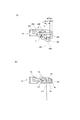
このようなシート給送装置として、大容量の収納デッキを有すると共に、収納デッキに収納されたシートをエアにより給紙するエア給紙技術を採用したシート給送装置がある(特許文献1参照)。そして、このシート給送装置では、例えば図14に示すように、シートを収納する不図示の収納デッキの上方にエア給紙方式のシート給送部400が配置されている。そして、シート給送部400は、吸着搬送ベルト21と、吸着搬送ベルト21内に配置された吸着ダクト51と、吸着ダクト51内を負圧にするための不図示の吸着ファンを備えている。
As such a sheet feeding device, there is a sheet feeding device that has a large-capacity storage deck and adopts an air feeding technology that feeds the sheets stored in the storage deck by air (see Patent Document 1). . In this sheet feeding apparatus, for example, as shown in FIG. 14, an air feeding type
収納デッキには、複数枚のシートSを載置して昇降可能に設けられた昇降台12と、載置された複数枚のシートSの後端の位置を規制するための後端規制板13が設けられている。また、収納デッキのシート給送方向下流には、シートSを浮上させて捌いて分離するため、シートSの先端側からエアを吹き付ける捌きノズル33及び分離ノズル34が設けられている。そして、この捌きノズル33及び分離ノズル34には、不図示の捌き・分離ファンを有するエア供給ユニット401が接続されており、このエア供給ユニット401により、捌きノズル33及び分離ノズル34にエアが供給される。
On the storage deck, a
次に、このような従来のシート給送部400のシート給送動作について説明する。シート給送動作が開始されると、シートSが載置された昇降台12が上昇を始め、やがて載置された複数枚のシートSの最上位のシートSaが、図14の(a)に示す、捌きノズル33の開口近傍の所定の位置に達するまで上昇する。この後、給紙命令を受けると、エア供給ユニット401の分離ファンが回転を始める。
Next, the sheet feeding operation of the conventional
これにより、捌きノズル33及び分離ノズル34から、矢印a及びbで示すように捌きエア及び分離エアが、積載された複数枚のシートSの上部部分の側端に向けて吹き出される。ここで、シートSは後端規制板13によって後方への移動が規制されているため、エアが吹き付けられた際、吹き付けられたエアはシートSの間に入り込み、これにより積載されたシートSの上部部分が浮上してシートSが捌かれる。
Thereby, as shown by arrows a and b, the separating air and the separating air are blown out from the separating
一方、給紙命令を受けた時点で吸着ファンが回転を開始するようになっており、これにより吸着ダクト51の内部が負圧状態になっている。このため、吸着ダクト51内に設けられた不図示の吸着シャッタを開くと、吸着搬送ベルト21に最上位のシートSaが吸着される。なお、このとき分離ノズル34によって吸着搬送ベルト21の下方に形成された分離エア流の効果により、最上位のシートSaと、それよりも下位のシートを確実に分離することができる。
On the other hand, the suction fan starts to rotate when a paper feed command is received, whereby the inside of the
この後、不図示の画像形成部の画像形成タイミングに合わせて吸着搬送ベルト21を回転させ、吸着搬送ベルト21のシート給送方向下流に配置された不図示の引抜きローラ対に受け渡すことで最上位のシートSaの給送が完了する。なお、引抜きローラ対にシートSaが受け渡された時点で、吸着シャッタを閉じ、再び吸着ダクト51の内部を負圧状態にして次の給紙に備える。以下、この動作を繰り返す。
Thereafter, the
ところで、このような大容量の収納デッキを備えたシート給送装置において、一般的に、シートの移動を規制する規制部である後端規制板は、シートのサイズに応じた後端規制位置に移動可能に設けられている。そして、シートを昇降台に載置する際、後端規制板を載置されたシートの後端に合わせるように移動させてセットする。また、収納デッキには、シートのシート給送方向と直交する幅方向の位置を規制する規制部である側端規制板が設けられており、シートを昇降台に載置する際、この側端規制板も載置されたシートの側端に合わせるように移動させてセットする。 By the way, in the sheet feeding apparatus having such a large-capacity storage deck, generally, the rear end regulating plate, which is a regulating unit that regulates the movement of the sheet, is positioned at the rear end regulating position according to the size of the sheet. It is provided to be movable. When the sheet is placed on the lifting platform, the rear end regulating plate is moved and set so as to match the rear end of the placed sheet. Further, the storage deck is provided with a side end regulating plate that is a regulating portion that regulates the position of the sheet in the width direction orthogonal to the sheet feeding direction. The restriction plate is also moved and set so as to be aligned with the side edge of the placed sheet.
しかし、例えば、後端規制板を移動させる際、後端規制板の移動が十分でなかったり、昇降台上に真っ直ぐにシートが載置されない状態で後端規制板をセットしたりした場合、後端規制板とシートとの間に隙間が生じてしまう。そして、このようにシートと後端規制板との間に隙間が生じた状態でシートにエアを吹き付けた場合、エアにより浮上したシートSが、図14の(b)に示すように後端規制板13との隙間分、シート給送方向と逆方向に後退してしまう。
However, for example, when the rear end regulating plate is moved, if the rear end regulating plate is not sufficiently moved, or the rear end regulating plate is set in a state where the sheet is not placed on the lifting platform, A gap is generated between the end regulating plate and the sheet. Then, when air is blown onto the sheet with the gap between the sheet and the rear end regulating plate in this way, the sheet S that has been lifted by the air has a rear end regulation as shown in FIG. The sheet moves backward in the direction opposite to the sheet feeding direction by the gap with the
この結果、分離エア及び捌きエア、吸着ダクトからの各エア流のバランスが崩れてシートSの浮上が不安定となり、シートの吸着搬送ベルト21への吸着不良が生じたり、複数枚のシートが吸着搬送ベルト21に吸着されたりすることがある。この場合には、シートSの給送不良やシートSが重送する等の問題が発生してしまう。
As a result, the balance of the air flows from the separation air, the firing air, and the suction duct is lost, and the sheet S is unstablely floated, and the suction of the sheet to the
なお、この問題は、エア給紙技術を採用したシート給送装置だけでなく、重送されたシートをリタードローラにより後端規制板側に戻すようにするリタードローラ方式を採用したシート給送装置でも発生する。即ち、リタードローラ方式のシート給送装置の場合でも、シートと後端規制板との間に隙間が生じた場合、リタードローラにより戻されたシートが後端規制板とシートとの隙間分後退する場合がある。そして、このような場合、シートの給送不良が発生する場合がある。 This problem is not only due to the sheet feeding device adopting the air feeding technology, but also the sheet feeding device adopting the retard roller method in which the double fed sheets are returned to the trailing edge regulating plate side by the retard roller. But it happens. That is, even in the case of a retard roller type sheet feeding device, if a gap is generated between the sheet and the trailing edge regulating plate, the sheet returned by the retard roller is retracted by the gap between the trailing edge regulating plate and the sheet. There is a case. In such a case, a sheet feeding failure may occur.
そこで、本発明は、このような現状に鑑みてなされたものであり、シートと規制部との間に隙間が生じた場合でも、確実にシートを給送することのできるシート給送装置及び画像形成装置を提供することを目的とするものである。 Therefore, the present invention has been made in view of such a current situation, and a sheet feeding device and an image that can reliably feed a sheet even when a gap is generated between the sheet and the regulating portion. An object of the present invention is to provide a forming apparatus.
本発明は、シート給送装置において、シートを支持する昇降可能なトレイと、前記トレイの上方に設けられたシート給送部とを備え、前記トレイの上昇により給送可能位置に達したシートを前記シート給送部によりシート給送方向に給送するシート給送装置において、前記トレイに支持されたシートのシート給送方向と反対方向への移動を規制する規制面を有する規制部と、前記トレイに支持されたシートの後端に当接可能に設けられると共に前記規制面よりも前記シート給送方向における下流に配置される当接面を有し、前記規制部に上下に移動可能に設けられるストッパ部と、を備え、前記ストッパ部は、前記トレイに支持されたシートが前記給送可能位置に達したときに、前記規制部と前記トレイに支持されたシートとの間に隙間が生じている場合には、前記当接面が前記隙間に位置してシートの前記シート給送方向と反対方向への移動を規制し、前記隙間が所定の寸法よりも狭い場合及び前記隙間がない場合には、前記トレイに支持されたシートの最上面に押されて退避する、ことを特徴とするものである。 The present invention provides a sheet feeding apparatus comprising: a tray capable of moving up and down to support a sheet; and a sheet feeding unit provided above the tray, wherein the sheet that has reached a feedable position by raising the tray is provided. in the sheet feeding unit sheet feeding apparatus for feeding a sheet feeding direction by a restricting portion having a restricting surface for restricting the movement in the direction opposite to the sheet feeding direction of the sheet supported on said tray, said Provided to be able to come into contact with the rear end of the sheet supported by the tray, and has a contact surface disposed downstream of the regulation surface in the sheet feeding direction, and provided to be movable up and down in the regulation unit. includes a stopper portion that is, wherein the stopper portion, when the sheet supported on the tray reaches the feed can position, a gap between the sheet supported on said tray and said restricting portion Living If it is, the positioned abutment surface the gap restricts the movement in the opposite direction as the sheet feeding direction of the sheet, if the gap is not narrow and when the gap than the predetermined size the retreats by being pushed by the uppermost surface of the sheet supported on said tray, it is characterized in.
本発明のように、シートと規制部との間に生じた隙間に突出するストッパ部によってシートの規制部の方向への移動を規制することにより、シートと規制部との間に隙間が生じた場合でも、確実にシートを給送することができる。 As in the present invention, by restricting the movement of the sheet in the direction of the restricting portion by the stopper portion protruding into the gap generated between the sheet and the restricting portion, a gap is generated between the sheet and the restricting portion. Even in this case, the sheet can be reliably fed.
以下、本発明の実施の形態を、図面を参照しながら詳細に説明する。図1は、本発明の第1の実施の形態に係るシート給送装置を備えた画像形成装置の一例であるプリンタの概略構成を示す図である。 Hereinafter, embodiments of the present invention will be described in detail with reference to the drawings. FIG. 1 is a diagram illustrating a schematic configuration of a printer that is an example of an image forming apparatus including a sheet feeding device according to a first embodiment of the present invention.
図1において、100はプリンタ、101はプリンタ本体である。このプリンタ本体101の上部には自動原稿給送装置120により原稿載置台としてのプラテンガラス120aに載置された原稿Dを読み取る画像読取部130が設けられている。また、画像読取部130の下方には画像形成部102と、画像形成部102にシートSを給送するシート給送装置103が設けられている。
In FIG. 1, 100 is a printer, and 101 is a printer body. An
ここで、画像形成部102には、感光ドラム112、現像器113、レーザスキャナユニット111等が設けられている。また、シート給送装置103は、OHT等のシートSを収容してプリンタ本体101に着脱自在な複数のシート収納部11及びシート収納部11に収納されたシートSを送り出す吸着搬送ベルト21等を備えている。
Here, the
次に、このような構成のプリンタ100の画像形成動作について説明する。プリンタ本体101に設けられている後述する図3に示す制御部Cから画像読取部130に画像読取信号が出力されると、画像読取部130により原稿Dの画像が読み取られる。この後、レーザスキャナユニット111から、この電気信号に対応したレーザ光が感光ドラム112上に照射される。このとき感光ドラム112は、予め帯電されおり、光が照射されることによって静電潜像が形成され、次いで静電潜像を現像器113によって現像することにより、感光ドラム上にトナー像が形成される。
Next, an image forming operation of the
一方、制御部から給紙信号がシート給送装置103に出力されると、シート収納部11からシートSが給送される。この後、給送されたシートSはレジストローラ117により感光ドラム上のトナー画像と同期を取って感光ドラム112と転写帯電器118とにより構成される転写部に送られる。次に、このように転写部に送られたシートは、トナー像が転写され、この後、定着部114に搬送される。さらにこの後、定着部114により加熱及び加圧されることにより、シートSに未定着転写画像が永久定着される。そして、このように画像が定着されたシートは排出ローラ116によりプリンタ本体101から排紙トレイ119に排出される。
On the other hand, when a paper feed signal is output from the control unit to the
図2は、シート給送装置103の構成を示す図である。シート収納部11は、昇降可能なトレイである昇降台12と、シートSのシート給送方向上流端である後端の位置を規制する後端規制板13と、先端規制板17と、シートSのシート給送方向と直交する幅方向の位置を規制する側端規制板14を備えている。なお、昇降台12に積載支持されたシートの移動を規制する規制部である後端規制板13及び側端規制板14は、収納されるシートのサイズによって位置を任意に変えられるように構成されている。また、後端規制板13には最上位シートSaのシート給送方向上流側端部である後端部の高さ位置を規制する後端上面規制部18が上下方向に移動可能に設けられている。
FIG. 2 is a diagram illustrating a configuration of the
このシート収納部11は、スライドレール15によりプリンタ本体101から引き出し可能となっており、シート収納部11がプリンタ本体から引き出されたときに昇降台12が所定の位置まで下降してシートの補充や交換等を行うことができる。なお、昇降台12は、ステッピングモータ又はDCサーボモータ等のリフタ駆動モータを備えた不図示のリフタ機構により昇降される。
The
さらに、このシート収納部11の上部にはシートを1枚ずつ分離して給送するためのエア給紙方式のシート給送部(以下、エア給紙部150という)が配置されている。このエア給紙部150は、昇降台12に積載されたシートSを吸着搬送する吸着搬送部20と、昇降台上の複数枚のシートSの上部部分を浮上させて捌くと共に、シートSを1枚ずつ分離するためのエア吹き付け部30とを備えている。
Further, an air feeding type sheet feeding unit (hereinafter referred to as an air feeding unit 150) for separating and feeding the sheets one by one is disposed on the upper portion of the
ここで、吸着搬送部20は、ベルト駆動ローラ41に掛け渡されると共にシートSを吸着して図中右方向に給送する吸着搬送ベルト21と、シートSを吸着搬送ベルト21に吸着させるための負圧を発生する吸着ファン36を備えている。また、吸着搬送ベルト21の内側に配置され、吸着搬送ベルト21に形成されている不図示の吸引穴を介してエアを吸引するための吸着ダクト51を備えている。さらに、吸着ファン36と吸着ダクト51との間に配置され、吸着搬送ベルト21の吸着動作をON/OFFする吸着シャッタ37を備えている。なお、本実施の形態において、吸着搬送ベルト21は、幅方向に所定の間隔を持って複数配置されている。
Here, the
また、エア吹き付け部30は、収納されているシートSの上部前側にエアを吹き付けるための捌きノズル33及び分離ノズル34と、捌き・分離ファン31と、各ノズル33,34に捌き・分離ファン31からエアを送る分離ダクト32を備えている。そして、捌き・分離ファン31により矢印c方向に吸い込まれたエアの一部は分離ダクト32を通過して捌きノズル33により矢印a方向に吹き付けられ、昇降台12上に積載されているシートSの上部のうち数枚を浮上させる。また、他のエアは分離ノズル34により矢印b方向に吹き付けられ、捌きノズル33により浮上したシートを1枚ずつ分離して吸着搬送ベルト21に吸着させる。
Further, the
なお、図3は、シート給送装置103の制御ブロック図である。制御部Cには、後述する図5に示す紙面検知機構に設けられた第1シート面センサ54及び第2シート面センサ55、シートの後端面を検知する後端シート面センサ56が接続される。また、吸着搬送ベルト21を駆動する吸着搬送ベルト駆動モータ21M、昇降台12を昇降させるリフタ駆動モータ12M、吸着シャッタ37を回転させる吸着シャッタソレノイド37SLが接続されている。また、制御部Cには、シートを吸着搬送ベルト21に吸着させるための負圧を発生する吸着ファン36、シートにエアを吹き付ける捌き・分離ファン31及びモニタ300が接続されている。
FIG. 3 is a control block diagram of the
次に、このように構成されたシート給送装置103(エア給紙部150)のシート給送動作について説明する。まず、ユーザーがシート収納部11を引き出してシートSをセットし、この後、所定の位置にシート収納部11を格納すると、まずリフタ駆動モータ12Mが駆動される。これにより、昇降台12が上昇し、積載支持したシートと吸着搬送ベルト21との距離が給送可能な距離となる位置に達すると、制御部Cは、この位置で昇降台12を停止させる。この後、給送を開始するためのシート給送信号に備える。
Next, a sheet feeding operation of the sheet feeding apparatus 103 (air feeding unit 150) configured as described above will be described. First, when the user pulls out the
次に、シート給送信号を検知すると、制御部Cは捌き・分離ファン31を作動させ、図4の(a)に示すように矢印c方向へエアを吸い込む。このエアは分離ダクト32を介して捌きノズル33、分離ノズル34からそれぞれ矢印a及びb方向からシートに吹き付けられる。これにより、複数枚のシートSのうちの上位の数枚のシートが浮上する。また、制御部Cは吸着ファン36を作動させ、図中F方向にエアを吐き出す。この際、吸着シャッタ37はまだ閉じられている。
Next, when a sheet feeding signal is detected, the controller C operates the separation /
次に、シート給送信号を検知してから所定時間が経過し、上位のシートの浮上が安定したところで、制御部Cは吸着シャッタソレノイド37SLを駆動し、図4の(b)に示すように吸着シャッタ37を矢印G方向に回転させる。これにより、吸着搬送ベルト21に設けられた吸引穴から矢印H方向へエアが吸引され、吸引力が発生する。そして、この吸着力と、分離ノズル34からの分離エアにより最上位のシートSaのみが吸着搬送ベルト21に吸着される。
Next, when a predetermined time elapses after the sheet feeding signal is detected and the upper sheet is stabilized, the controller C drives the suction shutter solenoid 37SL, as shown in FIG. 4B. The
続いて、制御部Cは、図3に示す吸着搬送ベルト駆動モータ21Mを駆動し、ベルト駆動ローラ41を矢印J方向に回転させる。これにより、吸着搬送ベルト21に吸着された状態で最上位のシートSaが矢印K方向に給送され、この後、矢印L,M方向に回転する引き抜きローラ対42により画像形成部に向けてシートSaが送られる。
Subsequently, the controller C drives the suction conveyance belt drive motor 21M shown in FIG. 3 to rotate the
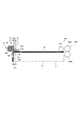
なお、シート給送装置103には、図5に示すように昇降台12に載置されているシートSの上面を検知するために、シートSの上面に当接する紙面検知機構49と、紙面検知機構49の高さを検知する2つのシート面センサ54,55とが設けられている。また、後端規制板13には、昇降台12に載置されたシートSの後端部上面に当接してシート後端の浮上を規制するための後端上面規制部18と、後端上面規制部18の位置を検知してシートの高さ位置を検知する後端シート面センサ56が配置されている。
The
ここで、この後端上面規制部18は、図6に示すように、後端規制板13の支持部13Eと係合する係合部18Aを備えている。これにより、後端上面規制部18は、後端規制板13に沿って、昇降台12に積載されたシートに上方から当接し、シートと一体的に昇降することができる。なお、支持部13Eに、ボールベアリングや表面の摩擦抵抗の低いローラ等を設けることにより、昇降がスムーズに行われるように構成することが望ましい。また、後端上面規制部18の最上部には、後端規制板13の後端規制面13Cから先端規制板側(昇降台側)に突出する突出部18Dが、支持軸18Bにより上方に回動可能に支持されている。そして、この突出部18Dは、通常はセットされた最上位のシートに、シートがないときは昇降台12の表面に当接する。また、この突出部18Dのシート当接面である底面には後端規制パッド18Eが貼り付けられている。
Here, as shown in FIG. 6, the rear end upper
さらに、後端上面規制部18は突出部18D及び後端規制パッド18Eを保持すると共に、上下方向にスライド移動可能なスライダ18Fを備えている。ここで、このスライダ18Fには、既述した図5に示すように後端シート面センサ56をON・OFFする後端シート面検知センサフラグ18Gが設けられている。これにより、後端上面規制部18は最上位のシートの動きに確実に追従することができ、後端シート面センサ56は後端上面規制部18の位置に基づいてシートの高さを検出することが可能となる。
Further, the rear end upper
次に、本実施の形態に係るシート給送時の昇降台12の昇降制御について図7に示すフローチャートを用いて説明する。制御部Cは、シート給送信号を受けると、給送準備を開始し、まず捌き・分離ファン31の回転を開始し、エアの吹き付けを開始してシートを浮上させる。この後、第1及び第2シート面センサ54,55がONとならない場合は(S1のN)、昇降台12を上昇させ(S2)、第1及び第2シート面センサ54,55がONとなると(S1のY)、後端シート面センサ56による紙面確認を開始する(S3)。
Next, the raising / lowering control of the raising / lowering
そして、後端シート面センサ56がONとならない場合は(S4のN)、昇降台12を上昇させる(S5)。この後、後端シート面センサ56がONとなると(S4のY)、次に第2シート面センサ55の信号により、最上位シートの位置が適正範囲にあるかを判断する。そして、第2シート面センサ55がONでない場合には(S6のN)、第2シート面センサ55がONとなるまで(S6のY)、昇降台12を上昇させる(S7)。
If the rear-end
次に、第2シート面センサ55がONとなると(S6のY)、すなわち昇降台12が給送可能位置に上昇すると、昇降台12を停止させ(S8)、この後、シートの給送を開始する(S9)。なお、このような制御を昇降台12にシートがN枚積載(支持)された場合には、N枚目のシートが給送されるまで繰り返し、N枚目のシートが給送されると(S10のY)、給送動作を終了する。
Next, when the second
ところで、本実施の形態においては、図8に示すように、後端上面規制部18の突出部18Dにはシート給送方向と反対方向へのシートの移動を規制するためのストッパ部である2つの後端規制爪18H,18Iが昇降台12の上方に突出して設けられている。なお、本実施の形態においては、後端規制爪を2つ設けているが、1つあるいは3つ以上設けても良い。
By the way, in this embodiment, as shown in FIG. 8, the
この後端規制爪18H,18I(第1の規制爪、第2の規制爪)は、支持軸18Bに、後端上面規制部18の突出部18Dの底面よりも下方に、シート側に突出して、かつ回動可能に取り付けられている。また、この後端規制爪18H,18Iは、昇降台12の上昇に伴ってシートが下方より圧接するまでは、図8の(a)に示すように自重により下方回動し、それぞれ規制部分である先端部(第1の当接面、第2の当接面)が後端規制面13Cから距離L1,L2だけ離れた位置に移動している。なお、後端規制パッド18Eは、後端規制面13Cから距離L3だけ突出して設けられている。
The rear
図8の(b)は、昇降台12が異常上昇した時の状態を示しており、昇降台12が異常上昇すると、昇降台12により後端規制パッド18Eがつぶれる。また、後端規制爪18H,18Iも、昇降台12により押圧され、後端規制爪18H,18Iの中央部に形成された突き当て部c,dが支持軸18Bに突き当たるまで上方回動する。
FIG. 8B shows a state when the
ところで、既述した、図5は、シートSが昇降台12に正常にセットされたときの状態を示しており、このとき後端規制面13Cと昇降台12にセットされたシートSとの隙間ΔLは、ΔL<L1となっている。なお、このように隙間ΔLが<L1となっている場合は、シートが後端規制板13に沿って滑らかに昇降できるので、シートの給送に影響を及ぼすことはない。
By the way, FIG. 5 described above shows a state when the sheet S is normally set on the
この場合、昇降台12の上昇に伴ってシートSが上昇を始めると、2つの後端規制爪18H,18Iは昇降台上(トレイ上)の最上位のシートSaにより押圧されて上方に回転退避する。さらに、最上位のシートSaが後端規制パッド18Eに接触すると、この後、シートSにより後端上面規制部18全体が上方に押し上げられる。
In this case, when the sheet S starts to rise as the
そして、このように後端上面規制部18が上方に押し上げられ、この後、既述したように後端シート面センサ56がONとなると、昇降台12の上昇動作が停止する。次に、給紙動作が開始され、シートに捌きエア、分離エアが吹き付けられ、上位のシートが浮上する。ここで、このように捌きエア、分離エアが吹き付けられた際、シートは後端が規制面18Cに突き当たるまで後退するが、隙間ΔLが<L1となっているので、ほとんど後退することはない。このため、分離エア及び捌きエア、吸着ダクトからの各エア流のバランスが保たれるようになり、この結果、シートSの浮上が安定し、給送不良や重送を発生することなくシートを給送することができる。
Then, the rear end upper
一方、図9の(a)は、シートSがセットされたとき後端規制面13CとシートSとの隙間ΔLが、L1<ΔL<L2となる場合を示している。この場合、昇降台12の上昇に伴ってシートSが上昇を始めると、後端規制面13Cに近い後端規制爪18Hは後端規制面13CとシートSとの隙間にあるため、後端規制面13Cから遠い後端規制爪18Iだけが最上位のシートSaにより押圧されて上方回動する。さらに、昇降台12が上昇して最上位のシートSaが後端規制パッド18Eに接触すると、後端上面規制部18全体が上方に押し上げられ、この後、後端シート面センサ56がONとなると、昇降台12の上昇動作が停止する。
On the other hand, FIG. 9A shows a case where the gap ΔL between the trailing
次に、給紙動作が開始され、シートに捌きエア、分離エアが吹き付けられ、上位のシートが浮上する。ここで、このように捌きエア、分離エアが吹き付けられた際、シートは後退するが、このとき後端規制面13Cに近い後端規制爪18Hは上方回動していないので、後退したシートの後端は、この後端規制爪18Hに突き当たる。この結果、シートは、L2−L1だけ移動するが、この移動距離はわずかであることから、シートはほとんど後退することはない。このため、分離エア及び捌きエア、吸着ダクトからの各エア流のバランスが保たれるようになってシートSの浮上が安定し、給送不良や重送を発生することなくシートが給送される。
Next, a sheet feeding operation is started, and air and separation air are blown onto the sheet, and the upper sheet floats. Here, when blowing air and separation air are blown in this way, the sheet moves backward, but at this time, the rear
図9の(b)は、シートSがセットされたとき後端規制面13CとシートSとの隙間ΔLが、さらに大きく、L2<ΔL<L3となる場合を示している。この場合、昇降台12の上昇に伴ってシートSが上昇を始めると、後端規制爪18H,18Iは共に後端規制面13CとシートSとの隙間にあるため上方回動しない。さらに、昇降台12が上昇して最上位のシートSaが後端規制パッド18Eに接触すると、後端上面規制部18全体が上方に押し上げられ、この後、後端シート面センサ56がONとなると、昇降台12の上昇動作が停止する。
FIG. 9B shows a case where the gap ΔL between the trailing
次に、給紙動作が開始され、シートに捌きエア、分離エアが吹き付けられ、上位のシートが浮上する。ここで、このように捌きエア、分離エアが吹き付けられた際、シートは後退するが、このとき後端規制爪18I,18Iは上方回動していないので、後退したシートの後端は、後端規制面13Cから遠い後端規制爪18Iに突き当たる。この結果、シートは、L3−L2だけ移動するが、この移動距離はわずかであることから、シートはほとんど後退することはない。このため、シートSの浮上が安定し、給送不良や重送を発生することなくシートが給送される。
Next, a sheet feeding operation is started, and air and separation air are blown onto the sheet, and the upper sheet floats. Here, when the blowing air and the separation air are blown in this way, the sheet moves backward. At this time, however, the rear
なお、後端規制面13Cと昇降台12にセットされたシートSとの隙間ΔLがL3<ΔLの場合がある。この場合は、昇降台12が上昇しても最上位のシートSaが後端規制パッド18Eに接触できず後端上面規制部18を上方に押し上げることができないため、後端シート面センサ56はONすることがない。しかし、この場合、紙面検知機構49の第1及び第2シート面センサ54,55によって最上位のシートSaが検知される。そして、この場合にはモニタ300により、後端規制板13のセット位置が適正位置にないため、セットをやり直すようにユーザーへ通知を行う。つまり、後端規制面13CとシートSとの間の隙間が所定距離以上の場合は、通知手段であるモニタ300により、セットをやり直すようにユーザーへ通知を行う。
Note that the gap ΔL between the rear
以上説明したように、本実施の形態においては、シートと後端規制板13の規制面18Cとの間に隙間ΔLが生じた場合でも、後端規制爪18H,18Iにより、捌きエア及び分離エアにより浮上したシートが後退するのを防止することができる。これにより、分離エア及び捌きエア、吸着ダクトからの各エア流の位置バランスが保たれるため、吸着不良や重送の発生を防止することができる。
As described above, in the present embodiment, even when the gap ΔL is generated between the sheet and the regulating
つまり、本実施の形態においては、隙間ΔLに突出するように設けた後端規制爪18H,18Iにより、シートSの後端規制板13の方向への移動を規制するようにしている。これにより、シートと規制部との間に隙間が生じた場合でも、確実にシートを給送することができる。
That is, in the present embodiment, the movement of the sheet S in the direction of the rear
ところで、これまではエア給送方式のシート給送装置について説明したが、本発明は、これに限らず、リタード給紙方式を採用したシート給送装置についても適用することができる。 By the way, although the sheet feeding apparatus of the air feeding system has been described so far, the present invention is not limited to this and can be applied to a sheet feeding apparatus adopting a retard sheet feeding system.
次に、このようにリタード給紙方式を採用した本発明の第2の実施の形態について説明する。図10は、本実施の形態に係るシート給送装置の構成を説明する図である。なお、図10において、既述した図5と同一符号は、同一又は相当部分を示している。 Next, a second embodiment of the present invention that employs the retard sheet feeding method will be described. FIG. 10 is a diagram illustrating the configuration of the sheet feeding apparatus according to the present embodiment. 10, the same reference numerals as those in FIG. 5 described above indicate the same or corresponding parts.
図10において、200はシート給送装置に設けられたシート給送部であり、このシート給送部200は、昇降台12上のシートSの最上位のシートSaを給送するピックアップローラ207を備えている。また、このシート給送部200は、ピックアップローラ207によって複数枚のシートが送り出された場合、最上位のシートSaと、他のシートとを分離する分離ローラ対208を備えている。
In FIG. 10,
この分離ローラ対208は、シートを給送する方向に回転するフィードローラ208Aと、フィードローラ208Aとの間でシートを1枚ずつ分離する分離ニップ部を形成するリタードローラ208Bとを備えている。ここで、このリタードローラ208Bは、シート給送方向と逆方向に回転可能に設けられ、フィードローラ208Aに圧接して分離ニップ部を形成する。なお、これらピックアップローラ207、フィードローラ208A及びリタードローラ208Bは、図11に示す制御部Cにより駆動制御される給紙駆動モータ207Mにより駆動される。
The pair of
次に、本実施の形態に係るシート給送装置のシート給送動作制御について図12に示すフローチャートを用いて説明する。制御部Cは、シート給送信号を受けると、給送準備を開始し、昇降台12を昇降させて後端シート面センサ56による紙面確認を開始する(S11)。そして、後端シート面センサ56がONとならない場合には(S12のN)、昇降台12を上昇させ(S13)、後端シート面センサ56がONとなると(S12のY)、昇降台12を停止させる(S14)。この後、シートの給送を開始する(S15)。なお、このような制御を昇降台12にシートがN枚積載(支持)された場合には、N枚目のシートが給送されるまで繰り返し、N枚目のシートが給送されると(S16のY)、給送動作を終了する。
Next, sheet feeding operation control of the sheet feeding apparatus according to the present embodiment will be described with reference to the flowchart shown in FIG. Upon receiving the sheet feeding signal, the control unit C starts preparation for feeding, raises and lowers the
ところで、本実施の形態において、昇降台12に積載されたシートがピックアップローラ207によって最上位のシートから順に送り出されると、分離ローラ対208により、最上位のシートのみ搬送される。しかし、環境条件やシートの種類等によっては、ピックアップローラ207により、複数のシートが、シート給送方向にズレを生じさせながら送り出される場合がある。この場合、最上位のシート以外の、複数のシートは分離ローラ対208によりシート給送方向と逆方向に搬送されるが、このとき、シート間でズレが生じている場合には、例えばは下方のシートの後端が後端規制板13に突き当たるまで搬送される場合がある。
By the way, in the present embodiment, when the sheets stacked on the
そこで、本実施の形態においても、既述した図10に示すように、後端上面規制部18の突出部18Dにシート給送方向と反対方向へシートが後退するのを防ぐための後端規制爪18H,18Iを設けている。なお、本実施の形態において、突出部18Dには後端規制パッド18Eの代わりに、ピックアップローラ207によるシートの送り出しの抵抗とならないように後端規制コロ18Jが取り付けられている。
Therefore, also in the present embodiment, as shown in FIG. 10 described above, the rear end restriction for preventing the sheet from retreating in the direction opposite to the sheet feeding direction to the
ここで、図10は、シートSがセットされたとき後端規制面13CとシートSとの隙間ΔLが、L1<ΔL<L2となる場合を示している。この場合、昇降台12の上昇に伴ってシートSが上昇を始めると、後端規制面13Cに近い後端規制爪18Hは後端規制面13CとシートSとの隙間にあるため、後端規制面13Cから遠い後端規制爪18Iだけが最上位のシートSaにより押圧されて上方回動する。さらに、最上位のシートSaが後端規制コロ18Jに接触すると、後端上面規制部18全体が上方に押し上げられ、この後、後端シート面センサ56がONとなると、昇降台12の上昇動作が停止する。
Here, FIG. 10 shows a case where the clearance ΔL between the trailing
この後、給紙動作が開始され、昇降台12に積載されたシートがピックアップローラ207によって最上位のシートから順に送り出される。ここで、ピックアップローラ207により、複数のシートが送り出された場合、最上位のシート以外の、複数のシートは分離ローラ対208によりシート給送方向と逆方向に搬送される。このとき、後端規制面13Cに近い後端規制爪18Hは上方回動していないので、後退したシートの後端は、この後端規制爪18Hに突き当たる。この結果、シートは、L2−L1だけ移動するが、この移動距離はわずかであることから、シートはほとんど後退することはない。このため、給送不良発生することなくシートを給送することができる。
Thereafter, the sheet feeding operation is started, and the sheets stacked on the
なお、後端規制面13Cと昇降台12におかれたシートSとの隙間ΔLがL2<ΔL<L3の場合は、昇降台12上のシートが上昇を始めても、シートは2つの後端規制爪18H,18Iには当接しない。このため、最上位のシート以外の、分離ローラ対208によりシート給送方向と逆方向に搬送される複数のシートの後端は、後端規制面13Cから遠い後端規制爪18Iに突き当たる。この結果、シートは、L3−L2だけ移動するが、この移動距離はわずかであることから、シートはほとんど後退することはない。このため、給送不良を発生することなくシートが給送される。
When the gap ΔL between the trailing
さらに、後端規制面13Cと昇降台12にセットされたシートSとの隙間ΔLがL3<ΔLの場合がある。この場合は、昇降台12が上昇しても最上位のシートSaが後端規制コロ18Jに接触できず後端上面規制部18を上方に押し上げることができないため、後端シート面センサ56はONすることはない。しかし、昇降台12が上昇を開始してから所定時間が経過しても後端シート面センサ56がONとならない場合には、モニタ300により、後端規制板13のセットをやり直すようにユーザーへ通知を行う。
Further, the gap ΔL between the rear
また、後端規制面13Cと昇降台12におかれたシートSとの隙間ΔLがΔL<L1となるように正常にシートが載置された場合、昇降台12の上昇に伴って2つの後端規制爪18H,18Iが最上位のシートSaにより押圧されて上方に回動する。このため、最上位のシート以外の、分離ローラ対208によりシート給送方向と逆方向に搬送される複数のシートは、後端が規制面18Cに突き当たるまで後退するが、隙間ΔLがΔL<L1となっているので、ほとんど後退することはない。このため、給送不良を発生することなくシートを給送するこができる。
Further, when the sheet is normally placed so that the gap ΔL between the rear
以上説明したように、本実施の形態においては、シートと後端規制板13の規制面18Cとの間に隙間ΔLが生じた場合でも、後端規制爪18H,18Iにより、リタードローラにより戻されたシートの後端規制板13の方向への移動を規制するようにしている。これにより、シートを安定して給送することができる。
As described above, in the present embodiment, even when the gap ΔL is generated between the sheet and the regulating
つまり、本実施の形態のように、リタード給紙方式を採用したシート給送装置においても、隙間ΔLに突出するように設けた後端規制爪18H,18Iにより、シートSの後端規制板13の方向への移動を規制することができる。これにより、シートと規制部との間に隙間ΔLが生じた場合でも、確実にシートを給送することができる。
That is, even in the sheet feeding apparatus employing the retard sheet feeding method as in the present embodiment, the trailing
なお、これまで説明した第1及び第2の実施の形態では、後端上面規制部18を上方に押し上げることができない場合には、後端規制面13CとシートSとの隙間ΔLがL3以上であるということを検出するようにしている。しかし、後端規制面13CとシートSとの隙間ΔLがL3以上であるということを検出する構成は、これに限らない。
In the first and second embodiments described so far, when the rear end upper
例えば、図13の(a)に示すように、後端規制面13CとシートSとの隙間ΔLがL3以上であるということを検出するためのセンサフラグ60を、後端規制板13に回動自在に設けるようにしても良い。そして、このセンサフラグ60を、隙間ΔLがL3以下の場合には、シートにより押圧されて後端シート面センサ56に検知されない位置に移動し、隙間ΔLがL3以上の場合には、回動して後端シート面センサ56をONする位置に移動するように構成する。これにより、隙間ΔLがL3以上のときは、センサフラグ60が回動して後端シート面センサ56がONとなるので、隙間ΔLがL3以上であるということを検出することができる。
For example, as shown in FIG. 13A, a
また、図13の(b)に示すように、隙間ΔLがL3以上であるということを検出するためのマーキング71が施された後端指標支持棒70を、後端規制板13に突出自在に設けるようにしても良い。そして、この後端指標支持棒70を、隙間ΔLがL3以下の場合には、シートにより押圧されて退避位置に移動し、隙間ΔLがL3以上の場合には、後端指標バネ72によりマーキング71が視認可能な位置まで突出するように構成する。これにより、隙間ΔLがL3以上のときは、マーキング71が視認できるので、隙間ΔLがL3以上であるということを直接ユーザーへ通知することができる。
Further, as shown in FIG. 13 (b), the rear end
また、これまではエア給紙及びリタード給紙技術を採用したシート給送装置について説明したが、同様の効果が得られるもので有ればどのような給紙技術でも適用可能である。また、これまでは昇降台12の上下動により、後端規制爪18H,18Iが退避する構成について説明したが、後端上面規制部18の上下動に連動して後端規制爪18H,18Iが退避するように構成しても良い。さらに、後端規制爪18H,18Iの退避方向を昇降台12の移動方向としたが、シートの移動が規制可能であれば退避方向はどの方向でもかまわない。
The sheet feeding apparatus adopting the air feeding and retard feeding technologies has been described so far, but any sheet feeding technology can be applied as long as the same effect can be obtained. In the above description, the rear
また、これまでの説明においては、後端規制板13に取り付けられた後端規制爪18H,18Iによりシートのズレを防止する構成を説明したが、本発明は、これに限らず、同様の効果が得られれば側端規制板にも適用することができる。例えば、サイドファンによりシートの側端にエアを吹き付ける場合、本発明を適用することにより、吹き付けられたエアにより、シートが対向する側の側端規制板にずれるのを防止することができる。
Further, in the description so far, the configuration for preventing the sheet from being displaced by the rear
11…シート収納部、12…昇降台、13…後端規制板、14…側端規制板、18…後端上面規制部、18H,18I…後端規制爪、20…吸着搬送部、30…エア吹き付け部、56…後端シート面センサ、100…プリンタ、101…プリンタ本体、102…画像形成部、103…シート給送装置、150…エア給紙部、200…シート給送部、207…ピックアップローラ、208…分離ローラ対、208A…フィードローラ、208B…リタードローラ、300…モニタ、C…制御部、S…シート、Sa…最上位のシート、ΔL…隙間
DESCRIPTION OF
Claims (9)
前記トレイに支持されたシートのシート給送方向と反対方向への移動を規制する規制面を有する規制部と、
前記トレイに支持されたシートの後端に当接可能に設けられると共に前記規制面よりも前記シート給送方向における下流に配置される当接面を有し、前記規制部に上下に移動可能に設けられるストッパ部と、を備え、
前記ストッパ部は、前記トレイに支持されたシートが前記給送可能位置に達したときに、前記規制部と前記トレイに支持されたシートとの間に隙間が生じている場合には、前記当接面が前記隙間に位置してシートの前記シート給送方向と反対方向への移動を規制し、前記隙間が所定の寸法よりも狭い場合及び前記隙間がない場合には、前記トレイに支持されたシートの最上面に押されて退避する、
ことを特徴とするシート給送装置。 A tray that can be moved up and down to support the sheet, and a sheet feeding unit provided above the tray, and a sheet that has reached a feedable position by raising the tray is fed in the sheet feeding direction by the sheet feeding unit. In the sheet feeding device for feeding to
A regulating portion having a regulating surface that regulates movement of the sheet supported by the tray in the direction opposite to the sheet feeding direction;
It has a contact surface that is arranged to be able to come into contact with the rear end of the sheet supported by the tray, and is arranged downstream of the regulation surface in the sheet feeding direction , and can be moved up and down in the regulation part. comprising a provided that the stopper portion,
The stopper portion, when the sheet supported on the tray reaches the feed can position, if a gap is formed between the sheet supported on said tray and said regulating portion, said those A contact surface is located in the gap to restrict the movement of the sheet in the direction opposite to the sheet feeding direction, and is supported by the tray when the gap is narrower than a predetermined dimension and when there is no gap. Evacuated by being pushed to the top surface of the sheet ,
A sheet feeding apparatus characterized by that.
前記ストッパ部は、前記上面規制部に回動可能に支持される、 The stopper portion is rotatably supported by the upper surface regulating portion.
ことを特徴とする請求項1に記載のシート給送装置。 The sheet feeding apparatus according to claim 1.
ことを特徴とする請求項2に記載のシート給送装置。 Before SL stopper portion is a lower than the bottom of said upper surface regulating portion, and is provided to protrude on the seat side which is supported,
The sheet feeding apparatus according to claim 2 , wherein the sheet feeding apparatus is a sheet feeding apparatus.
ことを特徴とする請求項1乃至3のいずれか1項に記載のシート給送装置。 The sheet feeding device according to any one of claims 1 to 3, wherein the sheet feeding device is provided.
ことを特徴とする請求項1乃至4のいずれか1項に記載のシート給送装置。 A sensor that detects that the gap between the restriction portion and the sheet is greater than or equal to a predetermined distance, and a notification that restarts the setting of the restriction portion based on detection of the sensor when the gap is greater than or equal to a predetermined distance. having, a notification unit that performs,
The sheet feeding device according to any one of claims 1 to 4, wherein the sheet feeding device is provided.
ことを特徴とする請求項1乃至5のいずれか1項に記載のシート給送装置。 The sheet feeding unit sucks and feeds the floated sheet by blowing air to the side edge of the sheet supported by the tray that has reached the feedable position to float the sheet. An adsorption conveyance unit, and the uppermost sheet floated by air blowing is adsorbed and conveyed by the adsorption conveyance unit .
Sheet feeding apparatus according to any one of claims 1 to 5, characterized in that.
ことを特徴とする請求項1乃至5のいずれか1項に記載のシート給送装置。 The sheet feeding unit is provided with a pickup roller that feeds a sheet supported by the tray, a feed roller that rotates in a sheet feeding direction, and a roller that is rotatable in a direction opposite to the sheet feeding direction, and is in pressure contact with the feed roller. And a retard roller for forming a separation nip portion for separating the sheets one by one from the feed roller, and the sheet fed to the separation nip portion is fed by the feed roller and the retard roller. by feeding in isolation,
Sheet feeding apparatus according to any one of claims 1 to 5, characterized in that.
前記第2の規制爪の前記第2の当接面は、前記規制部の前記規制面に対して、前記第1の規制爪の前記第1の当接面よりも遠い位置に配置される、
ことを特徴とする請求項1乃至7のいずれか1項に記載のシート給送装置。 The stopper portion has a first restriction claw having a first contact surface capable of contacting the rear end of the sheet, and a second restriction claw having a second contact surface capable of contacting the rear end of the sheet. With nails,
The second contact surface of the second restriction claw is disposed farther than the first contact surface of the first restriction claw with respect to the restriction surface of the restriction portion.
Sheet feeding apparatus according to any one of claims 1 to 7, characterized in that.
前記シート給送装置から給送されるシートに画像を形成する画像形成部と、を備えた、
ことを特徴とする画像形成装置。 A sheet feeding device according to any one of claims 1 to 8 ,
An image forming unit that forms an image on a sheet fed from the sheet feeding device ,
An image forming apparatus.
Priority Applications (2)
| Application Number | Priority Date | Filing Date | Title |
|---|---|---|---|
| JP2011240474A JP5854766B2 (en) | 2011-11-01 | 2011-11-01 | Sheet feeding apparatus and image forming apparatus |
| US13/650,407 US8833754B2 (en) | 2011-11-01 | 2012-10-12 | Sheet feeding apparatus and image forming apparatus |
Applications Claiming Priority (1)
| Application Number | Priority Date | Filing Date | Title |
|---|---|---|---|
| JP2011240474A JP5854766B2 (en) | 2011-11-01 | 2011-11-01 | Sheet feeding apparatus and image forming apparatus |
Publications (3)
| Publication Number | Publication Date |
|---|---|
| JP2013095559A JP2013095559A (en) | 2013-05-20 |
| JP2013095559A5 JP2013095559A5 (en) | 2015-01-29 |
| JP5854766B2 true JP5854766B2 (en) | 2016-02-09 |
Family
ID=48171580
Family Applications (1)
| Application Number | Title | Priority Date | Filing Date |
|---|---|---|---|
| JP2011240474A Active JP5854766B2 (en) | 2011-11-01 | 2011-11-01 | Sheet feeding apparatus and image forming apparatus |
Country Status (2)
| Country | Link |
|---|---|
| US (1) | US8833754B2 (en) |
| JP (1) | JP5854766B2 (en) |
Families Citing this family (6)
| Publication number | Priority date | Publication date | Assignee | Title |
|---|---|---|---|---|
| JP2015143156A (en) * | 2013-12-26 | 2015-08-06 | キヤノン株式会社 | paper feeding device |
| DE102015200170B4 (en) * | 2014-02-10 | 2023-08-03 | Heidelberger Druckmaschinen Ag | Device for sucking a sheet from a stack of sheets |
| JP6624506B2 (en) * | 2015-12-07 | 2019-12-25 | 株式会社リコー | Paper feeder, image forming apparatus, and image forming system |
| JP6686476B2 (en) * | 2016-01-29 | 2020-04-22 | ブラザー工業株式会社 | Sheet conveying device and image recording device |
| JP7309375B2 (en) | 2019-01-31 | 2023-07-18 | キヤノン株式会社 | sheet conveying device |
| JP7424153B2 (en) * | 2020-03-24 | 2024-01-30 | 富士フイルムビジネスイノベーション株式会社 | Sheet feeding device and image forming device |
Family Cites Families (26)
| Publication number | Priority date | Publication date | Assignee | Title |
|---|---|---|---|---|
| NL9000637A (en) * | 1989-04-28 | 1990-11-16 | Seikosha Kk | PAPER FEEDER. |
| DE69227551T2 (en) | 1991-08-21 | 1999-05-27 | Canon Kk | Automatic sheet feeder |
| US5358230A (en) | 1992-04-24 | 1994-10-25 | Canon Kabushiki Kaisha | Sheet supplying apparatus |
| US5344133A (en) * | 1993-02-25 | 1994-09-06 | Eastman Kodak Company | Vacuum belt feeder having a positive air pressure separator and method of using a vacuum belt feeder |
| US5793399A (en) | 1993-12-27 | 1998-08-11 | Canon Kabushiki Kaisha | Sheet supplying apparatus |
| DE69529439T2 (en) | 1994-07-29 | 2003-06-26 | Canon Kk | Apparatus for feeding sheets |
| JP3311157B2 (en) | 1994-07-29 | 2002-08-05 | キヤノン株式会社 | Sheet material feeding device and recording device |
| US5876030A (en) * | 1996-05-03 | 1999-03-02 | Eastman Kodak Company | Apparatus for facilitating handling tab stock in a top feed vacuum corrugated feeder |
| JPH09118439A (en) * | 1995-10-24 | 1997-05-06 | Daiwa Seiko Inc | Paper feed cassette |
| JP3363699B2 (en) | 1996-04-10 | 2003-01-08 | キヤノン株式会社 | Sheet guide member, sheet feeding device, and image forming apparatus |
| JP3349360B2 (en) * | 1996-09-13 | 2002-11-25 | シャープ株式会社 | Paper feeder |
| US6015144A (en) * | 1997-04-18 | 2000-01-18 | Fuji Xerox Co., Ltd. | Sheet feeder and image forming apparatus |
| US6200043B1 (en) | 1998-04-15 | 2001-03-13 | Canon Kabushiki Kaisha | Sheet feeding apparatus and image forming apparatus having such sheet feeding apparatus |
| US7458570B2 (en) * | 2004-09-13 | 2008-12-02 | Ricoh Printing Systems, Ltd. | Sheet-supplying device |
| JP2006327805A (en) * | 2005-05-30 | 2006-12-07 | Konica Minolta Business Technologies Inc | Paper feeding device and image forming device |
| JP4684184B2 (en) * | 2005-09-20 | 2011-05-18 | 株式会社リコー | Sheet conveying apparatus and image forming apparatus |
| US7588244B2 (en) * | 2005-11-25 | 2009-09-15 | Ricoh Printing Systems, Ltd. | Sheet feeder with optical sensor |
| JP4677354B2 (en) * | 2006-02-21 | 2011-04-27 | キヤノン株式会社 | Sheet feeding apparatus and image forming apparatus |
| US7635129B2 (en) * | 2006-08-11 | 2009-12-22 | Ricoh Company, Ltd | Sheet conveying apparatus and image forming apparatus |
| JP4777211B2 (en) * | 2006-10-13 | 2011-09-21 | キヤノン株式会社 | Sheet feeding apparatus and image forming apparatus |
| JP2008094596A (en) * | 2006-10-16 | 2008-04-24 | Konica Minolta Business Technologies Inc | Paper feeder and image forming apparatus |
| JP4818974B2 (en) * | 2007-03-30 | 2011-11-16 | 株式会社リコー | Paper feeding cassette and image forming apparatus |
| JP5366574B2 (en) * | 2008-10-09 | 2013-12-11 | キヤノン株式会社 | Sheet feeding apparatus and image forming apparatus |
| US8419008B2 (en) | 2009-01-30 | 2013-04-16 | Canon Kabushiki Kaisha | Image forming apparatus |
| JP5623173B2 (en) | 2010-07-30 | 2014-11-12 | キヤノン株式会社 | Sheet conveying apparatus, image forming apparatus, and image reading apparatus |
| JP5822585B2 (en) | 2011-07-28 | 2015-11-24 | キヤノン株式会社 | Image forming apparatus |
-
2011
- 2011-11-01 JP JP2011240474A patent/JP5854766B2/en active Active
-
2012
- 2012-10-12 US US13/650,407 patent/US8833754B2/en active Active
Also Published As
| Publication number | Publication date |
|---|---|
| JP2013095559A (en) | 2013-05-20 |
| US8833754B2 (en) | 2014-09-16 |
| US20130106044A1 (en) | 2013-05-02 |
Similar Documents
| Publication | Publication Date | Title |
|---|---|---|
| JP5306249B2 (en) | Sheet feeding apparatus and image forming apparatus | |
| JP5854766B2 (en) | Sheet feeding apparatus and image forming apparatus | |
| US7635125B2 (en) | Sheet feeding apparatus and image forming apparatus | |
| JP5366574B2 (en) | Sheet feeding apparatus and image forming apparatus | |
| US7744081B2 (en) | Image forming apparatus | |
| JP5787611B2 (en) | Sheet feeding apparatus and image forming apparatus | |
| JP4968923B2 (en) | Tabbed sheet support unit, sheet feeding apparatus, and image forming apparatus | |
| JP5885427B2 (en) | Sheet feeding apparatus and image forming apparatus | |
| US7850162B2 (en) | Sheet feeding device and image forming apparatus | |
| JP2011032062A (en) | Sheet feeder and image forming device | |
| JP2013028433A (en) | Sheet feeding device and image forming apparatus | |
| US8480074B2 (en) | Sheet feeding device and image forming apparatus | |
| JP2007197097A (en) | Sheet feeding device and image forming device equipped with the same | |
| JP2006264834A (en) | Sheet feeding device and image forming device | |
| JP5258605B2 (en) | Sheet feeding apparatus and image forming apparatus | |
| JP5440920B2 (en) | Sheet conveying apparatus and image forming apparatus | |
| JP2009001408A (en) | Sheet feeder and image forming device | |
| JP7278176B2 (en) | sheet feeder | |
| JP2012046278A (en) | Sheet feeding device, and image forming apparatus | |
| JP2012171743A (en) | Sheet feeding device, and image forming apparatus |
Legal Events
| Date | Code | Title | Description |
|---|---|---|---|
| RD04 | Notification of resignation of power of attorney |
Free format text: JAPANESE INTERMEDIATE CODE: A7424 Effective date: 20130228 |
|
| A621 | Written request for application examination |
Free format text: JAPANESE INTERMEDIATE CODE: A621 Effective date: 20141023 |
|
| A521 | Written amendment |
Free format text: JAPANESE INTERMEDIATE CODE: A523 Effective date: 20141209 |
|
| A977 | Report on retrieval |
Free format text: JAPANESE INTERMEDIATE CODE: A971007 Effective date: 20150810 |
|
| A131 | Notification of reasons for refusal |
Free format text: JAPANESE INTERMEDIATE CODE: A131 Effective date: 20150818 |
|
| A521 | Written amendment |
Free format text: JAPANESE INTERMEDIATE CODE: A523 Effective date: 20151016 |
|
| TRDD | Decision of grant or rejection written | ||
| A01 | Written decision to grant a patent or to grant a registration (utility model) |
Free format text: JAPANESE INTERMEDIATE CODE: A01 Effective date: 20151110 |
|
| A61 | First payment of annual fees (during grant procedure) |
Free format text: JAPANESE INTERMEDIATE CODE: A61 Effective date: 20151208 |
|
| R151 | Written notification of patent or utility model registration |
Ref document number: 5854766 Country of ref document: JP Free format text: JAPANESE INTERMEDIATE CODE: R151 |