JP4777211B2 - Sheet feeding apparatus and image forming apparatus - Google Patents
Sheet feeding apparatus and image forming apparatus Download PDFInfo
- Publication number
- JP4777211B2 JP4777211B2 JP2006280658A JP2006280658A JP4777211B2 JP 4777211 B2 JP4777211 B2 JP 4777211B2 JP 2006280658 A JP2006280658 A JP 2006280658A JP 2006280658 A JP2006280658 A JP 2006280658A JP 4777211 B2 JP4777211 B2 JP 4777211B2
- Authority
- JP
- Japan
- Prior art keywords
- sheet
- sheet feeding
- pressing member
- rear end
- regulating member
- Prior art date
- Legal status (The legal status is an assumption and is not a legal conclusion. Google has not performed a legal analysis and makes no representation as to the accuracy of the status listed.)
- Expired - Fee Related
Links
Images


Classifications
-
- B—PERFORMING OPERATIONS; TRANSPORTING
- B65—CONVEYING; PACKING; STORING; HANDLING THIN OR FILAMENTARY MATERIAL
- B65H—HANDLING THIN OR FILAMENTARY MATERIAL, e.g. SHEETS, WEBS, CABLES
- B65H3/00—Separating articles from piles
- B65H3/08—Separating articles from piles using pneumatic force
- B65H3/12—Suction bands, belts, or tables moving relatively to the pile
- B65H3/124—Suction bands or belts
- B65H3/128—Suction bands or belts separating from the top of pile
-
- B—PERFORMING OPERATIONS; TRANSPORTING
- B65—CONVEYING; PACKING; STORING; HANDLING THIN OR FILAMENTARY MATERIAL
- B65H—HANDLING THIN OR FILAMENTARY MATERIAL, e.g. SHEETS, WEBS, CABLES
- B65H3/00—Separating articles from piles
- B65H3/46—Supplementary devices or measures to assist separation or prevent double feed
- B65H3/48—Air blast acting on edges of, or under, articles
-
- B—PERFORMING OPERATIONS; TRANSPORTING
- B65—CONVEYING; PACKING; STORING; HANDLING THIN OR FILAMENTARY MATERIAL
- B65H—HANDLING THIN OR FILAMENTARY MATERIAL, e.g. SHEETS, WEBS, CABLES
- B65H3/00—Separating articles from piles
- B65H3/46—Supplementary devices or measures to assist separation or prevent double feed
- B65H3/54—Pressing or holding devices
-
- B—PERFORMING OPERATIONS; TRANSPORTING
- B65—CONVEYING; PACKING; STORING; HANDLING THIN OR FILAMENTARY MATERIAL
- B65H—HANDLING THIN OR FILAMENTARY MATERIAL, e.g. SHEETS, WEBS, CABLES
- B65H2405/00—Parts for holding the handled material
- B65H2405/10—Cassettes, holders, bins, decks, trays, supports or magazines for sheets stacked substantially horizontally
- B65H2405/11—Parts and details thereof
- B65H2405/114—Side, i.e. portion parallel to the feeding / delivering direction
- B65H2405/1142—Projections or the like in surface contact with handled material
- B65H2405/11425—Projections or the like in surface contact with handled material retractable
-
- B—PERFORMING OPERATIONS; TRANSPORTING
- B65—CONVEYING; PACKING; STORING; HANDLING THIN OR FILAMENTARY MATERIAL
- B65H—HANDLING THIN OR FILAMENTARY MATERIAL, e.g. SHEETS, WEBS, CABLES
- B65H2511/00—Dimensions; Position; Numbers; Identification; Occurrences
- B65H2511/20—Location in space
-
- B—PERFORMING OPERATIONS; TRANSPORTING
- B65—CONVEYING; PACKING; STORING; HANDLING THIN OR FILAMENTARY MATERIAL
- B65H—HANDLING THIN OR FILAMENTARY MATERIAL, e.g. SHEETS, WEBS, CABLES
- B65H2701/00—Handled material; Storage means
- B65H2701/10—Handled articles or webs
- B65H2701/13—Parts concerned of the handled material
- B65H2701/131—Edges
- B65H2701/1313—Edges trailing edge
Landscapes
- Engineering & Computer Science (AREA)
- Mechanical Engineering (AREA)
- Sheets, Magazines, And Separation Thereof (AREA)
- Paper Feeding For Electrophotography (AREA)
Description
本発明は、シート給送装置及び画像形成装置に関し、特にシート収納部に収納されたシートの端部を規制する端部規制部材の構成に関する。 The present invention relates to a sheet feeding device and an image forming apparatus, and more particularly to a configuration of an end portion regulating member that regulates an end portion of a sheet stored in a sheet storage portion.
従来、複写機、電子写真プリンタ、インクジェットプリンタ、ファクシミリ、印刷装置等の画像形成装置においては、複数のシートが収納されたシート収納部からシートを1枚ずつ給送するシート給送装置を備えている。 2. Description of the Related Art Conventional image forming apparatuses such as copying machines, electrophotographic printers, inkjet printers, facsimile machines, and printing apparatuses include a sheet feeding device that feeds sheets one by one from a sheet storage unit that stores a plurality of sheets. Yes.
このシート給送装置は、表面がゴム等の弾性体で構成された給送ローラの回転摩擦によって、シート収納部の一例であるシート積載トレイ上に積載されたシートの搬送を行う方式のものが一般的である。この方式の場合、給送性能は給送ローラの表面の摩擦係数によるところが大きい。従って、給送ローラの摩擦による外形変化、材質の経時変化、紙粉の付着等による給送ローラ表面の摩擦係数の変化等により給送性能が不安定であったり、各種表面状態の違うシートに対応しきれないという欠点があった。 This sheet feeding apparatus has a method of transporting sheets stacked on a sheet stacking tray which is an example of a sheet storage unit by rotational friction of a feeding roller whose surface is made of an elastic body such as rubber. It is common. In this system, the feeding performance largely depends on the friction coefficient of the surface of the feeding roller. Therefore, the feeding performance is unstable due to changes in the outer shape due to friction of the feeding roller, changes in material over time, changes in the friction coefficient of the surface of the feeding roller due to adhesion of paper dust, etc. There was a drawback that it could not cope.
このようなことから、昨今、エアの吸引力及び無端ベルトの搬送力を利用してシート積載トレイ上に積載されたシートを吸着搬送するエア吸着方式を用いたシート給送装置が提案されている。 For these reasons, recently, a sheet feeding apparatus using an air suction method for sucking and transporting sheets stacked on a sheet stacking tray using air suction force and endless belt transport force has been proposed. .
このエア吸着方式ではシート積載トレイ上に積載したシートの端面に、エア吹き付け手段によってエアを吹き付けてシート間に空気層を形成することにより、上層部のシートを浮遊させてシート間の密着力を弱めるのが一般的である。なお、このようなエア吸着方式としては、例えば、エア吹き付けに伴うシートの浮遊をシート押え部材により規定の位置で規制することにより、シート間に入ったエアを貫通させ、密着力を弱めるようにしたものがある。 In this air adsorption method, air is blown onto the end surfaces of the sheets stacked on the sheet stacking tray by air blowing means to form an air layer between the sheets, thereby floating the upper layer sheet and improving the adhesion between the sheets. It is common to weaken. In addition, as such an air adsorption method, for example, by restricting the floating of the sheet accompanying the air blowing at a specified position by the sheet pressing member, the air that has entered between the sheets is penetrated, and the adhesion force is weakened. There is what I did.
ここで、このようにシート間に空気層を形成した場合、浮き上がった上層部のシートと、浮き上がらない他のシートとの間の抵抗が小さくなる。このため、無端ベルトにより吸着搬送された後、最上位シートを給送ローラで給送する際、他の上層部のシートが連れ送り(重送)される。 Here, when the air layer is formed between the sheets as described above, the resistance between the sheet of the upper layer part that floats and the other sheet that does not float is reduced. For this reason, after the uppermost sheet is fed by the feed roller after being sucked and conveyed by the endless belt, the other upper layer sheet is fed (multi-feed).
そこで、このような重送対策として、例えば給送ローラの下流にリタードローラ部を設けると共に、上層部のシートに作用する戻り防止手段として後端押え部材をシート積載部の後端に設けるようにしている(特許文献1参照)。 Therefore, as a countermeasure against such double feeding, for example, a retard roller portion is provided downstream of the feeding roller, and a trailing edge pressing member is provided at the trailing edge of the sheet stacking portion as a return preventing means that acts on the upper layer sheet. (See Patent Document 1).
ところで、従来のシート給送装置において、部品コスト低減やメンテナンス性向上のために、リタードローラ部を設けず、エア等の簡易的な戻し手段を用いたようなものが提案されている。このようなシート給送装置の場合、既述した特許文献1に示すような、戻り防止効果を目的とした後端押え部材では、給送方向の抵抗が少ない。
By the way, in the conventional sheet feeding apparatus, in order to reduce the component cost and improve the maintainability, there has been proposed one using a simple return means such as air without providing the retard roller portion. In the case of such a sheet feeding device, the trailing end pressing member for the purpose of preventing return as shown in
このため、使用環境(気温、湿度等)によって発生するシートのカール(屈曲)や、シートの厚み及び表面性により、後述する図7の(c)に示すように給送された最上位シートに連れられて、2枚目のシートも給送方向に送られ易く、重送を起こしやすくなる。 For this reason, due to the curl (bending) of the sheet caused by the use environment (air temperature, humidity, etc.) and the thickness and surface property of the sheet, the uppermost sheet fed as shown in FIG. With this, the second sheet is also easily fed in the feeding direction, and double feeding is likely to occur.
さらに、シートのカール(屈曲)や、シートの厚み、剛体差によるシート物性差により、給送時の、特に後端部における最上位シートの高さが変更する。 Further, the height of the uppermost sheet at the time of feeding, particularly at the rear end portion, is changed by the sheet curl (bending), the sheet thickness, and the sheet physical property difference due to the rigid body difference.
また、シートを無端ベルトに吸着させるためのエア吸着部は一般的に、吸引装置のサイズ等の兼ね合いから、給送ローラ寄りに設けられていることから、ラージサイズのシートの場合、シートの後端縁までは無端ベルトに吸着されることはない。このため、エア吸着された部分(シートの略中央から給送ローラ寄り)を頂点にして、シートの後端部周辺が垂れた山形形状になり、積載時の山形形状の形によって、後端部の上面高さ位置が不安定になりやすい。 In addition, since the air adsorbing part for adsorbing the sheet to the endless belt is generally provided closer to the feeding roller in consideration of the size of the suction device, in the case of a large size sheet, The end edge is not attracted to the endless belt. For this reason, the air-adsorbed portion (from the approximate center of the sheet toward the feeding roller) is the apex, and the periphery of the rear end of the sheet hangs down. Depending on the shape of the chevron when stacked, the rear end The top surface height position is likely to be unstable.
したがって、後端押え部材の高さ方向の位置が固定されている場合、シートの積載高さが、シートのカールや厚み、剛体差等によって変わった時に、常に一定の圧力でシートの後端を押えることが不可能になる。 Therefore, when the position of the trailing edge pressing member in the height direction is fixed, the trailing edge of the sheet is always kept at a constant pressure when the stacking height of the sheet changes due to the curl, thickness, rigidity difference, etc. of the sheet. It becomes impossible to hold down.
このため、シートの後端部を押える場合、後端押え部材の当接圧を常時、一定に設定するためには、最低限、前述した要因による最上位シートの高さが変更する領域分だけは後端押え部材を積載高さ方向に追従移動可能にしておく必要がある。 For this reason, when pressing the trailing edge of the sheet, in order to always set the contact pressure of the trailing edge pressing member constant, at least the region where the height of the uppermost sheet changes due to the above-described factors. In this case, the rear end pressing member needs to be movable in the stacking height direction.
さらに、後端押え部材を積載シートに上方から常に当接させる必要がある場合、確実にシートの上面を押えるようにするためには、シートの積載上限高さを後端押え部材の最下端位置よりも、低い位置までに予め制限する必要がある。 Furthermore, when it is necessary to always contact the trailing edge pressing member with the stacked sheet from above, in order to reliably press the upper surface of the sheet, the upper limit height of the sheet stacking is set to the lowest position of the trailing edge pressing member. It is necessary to limit to a lower position in advance.
しかし、このようにシートの積載上限高さを後端押え部材の最下端位置よりも低い位置に制限した場合、積載枚数が制限されることになり、装置の給紙容量が減る、という不具合が発生する。 However, when the upper limit height of sheet stacking is limited to a position lower than the lowermost position of the trailing edge pressing member, the number of stacked sheets is limited, and the sheet feeding capacity of the apparatus is reduced. appear.
なお、シートを積載した後、後端押え部材を、積載された最上位シートよりも上方に持ち上げることができるようにすれば、後端押え部材の最下端位置よりも高い位置までシートを積載することができる。しかし、この場合、後端押え部材を、最上位シートに上方から当接するように持ち上げるようにする必要がある。 If the trailing edge pressing member can be lifted above the stacked uppermost sheet after the sheets are stacked, the sheet is stacked up to a position higher than the lowermost position of the trailing edge pressing member. be able to. However, in this case, it is necessary to lift the rear end pressing member so as to contact the uppermost sheet from above.
ところで、通常、後端押え部材はシートの後端部を押えるために、シートの後端を規制する後端規制部材に設けられることが多い。この後端規制部材は、積載するシートのサイズは多岐にわたるため、サイズ変更の都度、固定を解除してサイズに合わせて移動させる必要がある。 By the way, usually, the trailing edge pressing member is often provided on a trailing edge regulating member that regulates the trailing edge of the sheet in order to hold the trailing edge of the sheet. Since the trailing edge regulating member has various sizes of sheets to be stacked, it is necessary to release the fixing and move according to the size every time the size is changed.
このように後端規制部材が移動するとき、シートを後端押え部材の最下端位置よりも高い位置まで積載していた場合、後端押え部材を持ち上げていないと、後端押え部材の先端がシートの積載端面に突き当たった状態でセットされる可能性がある。 When the trailing edge regulating member moves in this way, if the sheet is stacked up to a position higher than the lowest end position of the trailing edge pressing member, the leading edge of the trailing edge pressing member is not lifted unless the trailing edge pressing member is lifted. There is a possibility that the sheet is set in a state where it is in contact with the stacking end surface of the sheet.
例えば、後端規制部材を大サイズのシートに対応した位置から、小サイズのシートに対応した位置に変更する時、シートをセットしてから、後端規制部材をシート後端に合わせることが多い。この場合、後端押え部材を持ち上げていないと、後述する図13に示すように、後端押え部材の先端がシートの積載端面に突き当たった状態で誤ってセットされる可能性がある。 For example, when the rear end regulating member is changed from a position corresponding to a large size sheet to a position corresponding to a small size sheet, the rear end regulating member is often aligned with the rear end of the sheet after the sheet is set. . In this case, if the trailing edge pressing member is not lifted, there is a possibility that the trailing edge pressing member is erroneously set in a state where the leading edge of the trailing edge pressing member abuts against the sheet stacking end surface as shown in FIG.
この結果、後端押え部材は最上位シートに上方から当接していないため、上層部のシートは押えられず、重送しやすい状態になる。また、後端規制部材もシートの後端面に当接していないため、ピックアップ時のばらつきが生じ、シート給送タイミングのずれが生じる。 As a result, since the rear end pressing member is not in contact with the uppermost sheet from above, the upper layer sheet is not pressed, and it becomes easy to double feed. In addition, since the trailing edge regulating member is not in contact with the trailing edge surface of the sheet, variation occurs at the time of pickup, and a deviation in sheet feeding timing occurs.
したがって、後端規制部材をシートサイズに応じた位置に移動させるためには、固定を解除して後端規制部材をシート積載端面に合わせるように移動させながら、シート押え手段を上方に退避させる動作が必要となり、シート積載時の操作性が非常に悪かった。 Therefore, in order to move the trailing edge regulating member to the position corresponding to the sheet size, the operation of retracting the sheet pressing unit upward is performed while releasing the fixing and moving the trailing edge regulating member to match the sheet stacking end surface. Was necessary, and the operability when loading sheets was very poor.
そこで、本発明は、このような現状に鑑みてなされたものであり、シート積載時の操作性を向上させることのできるシート給送装置及び画像形成装置を提供することを目的とするものである。 Accordingly, the present invention has been made in view of such a situation, and an object of the present invention is to provide a sheet feeding apparatus and an image forming apparatus that can improve operability at the time of stacking sheets. .
本発明は、シート収納部に収納されたシートを給送するシート給送装置において、前記シート収納部にシート給送方向に移動自在に設けられ、前記シート収納部に収納されたシートの端部位置を規制する端部規制部材と、前記端部規制部材に移動自在に設けられ、底部に前記シート収納部に設けられたレール歯型に噛み合う歯型部を有し、前記歯型部が前記レール歯型に上下から係脱自在に係止して前記端部規制部材をシートサイズに応じた端部規制位置に保持する保持部と、
前記端部規制部材に上下方向に移動自在に設けられ、前記端部規制部材により端部位置が規制されたシートの端部の上面に上方から当接して押える端部押え部材と、前記端部規制部材を移動する際に、前記保持部による前記端部規制部材の係止を解除させると共に前記端部押え部材をシートの端部の上面から上方に移動させる解除機構と、を備え、前記解除機構は、前記端部規制部材におけるシートの端部が当接する当接面の側方に配置された1つの操作部と、前記操作部の操作に連動して前記保持部による前記端部規制部材の係止を解除させる第1の解除機構と、前記端部押え部材をシートの端部の上面から上方に移動させる第2の解除機構と、有し、前記操作部の操作により、前記第1の解除機構により前記保持部の前記歯型部が前記レール歯型から離間して前記端部規制部材の係止を解除すると共に、前記第2の解除機構により前記端部押え部材をシートの端部の上面から上方に移動させることを特徴とするものである。
The present invention provides a sheet feeding device that feeds a sheet stored in a sheet storage unit, and is provided in the sheet storage unit so as to be movable in a sheet feeding direction, and an end portion of the sheet stored in the sheet storage unit An end regulating member that regulates the position; and a tooth mold portion that is movably provided on the end regulating member and meshes with a rail tooth mold provided on the seat storage portion at the bottom, and the tooth mold portion is a holding portion for holding the upper and lower or al engaging detachably locked with and the end portion regulating member to the rail teeth type end restricting position corresponding to the sheet size,
An end pressing member that is provided on the end regulating member so as to be movable in the vertical direction and presses against an upper surface of the end of the sheet whose end position is regulated by the end regulating member from above, and the end when moving regulating member, and a release mechanism for moving upwards said end pressing member from the upper surface of the end portion of the sheet with to release the engagement of said end regulating member by said holding unit, the release The mechanism includes a single operation portion disposed on a side of a contact surface with which an end portion of the sheet contacts in the end portion restriction member, and the end portion restriction member by the holding portion in conjunction with the operation of the operation portion. And a second release mechanism for moving the end pressing member upward from the upper surface of the end portion of the sheet, and by operating the operation portion, the first release mechanism is released. The tooth mold part of the holding part is moved by the release mechanism. Apart from Le-toothed with releasing the engagement of said end regulating member, by the second release mechanism which and moving upwards said end pressing member from the upper surface of the end portion of the sheet It is.
本発明のように、端部規制部材を移動する際に、保持部による端部規制部材の係止を解除させると共に端部押え部材を収納されたシートの端部の上面から上方に移動させるようにすることにより、シート積載時の操作性を向上させることができる。 As in the present invention, when the end regulating member is moved, the end regulating member is unlocked by the holding unit and the end pressing member is moved upward from the upper surface of the end of the stored sheet. By doing so, the operability during sheet stacking can be improved.
以下、本発明を実施するための最良の形態を図面を用いて詳細に説明する。 The best mode for carrying out the present invention will be described below in detail with reference to the drawings.
図1は、本発明の実施の形態に係るシート給送装置を備えた画像形成装置の一例であるカラーレーザプリンタの概略構成を示す図である。図1において、100はカラーレーザプリンタ、100Aはカラーレーザプリンタ本体(以下、プリンタ本体という)、300は画像読取部、301はスキャナである。
FIG. 1 is a diagram illustrating a schematic configuration of a color laser printer which is an example of an image forming apparatus including a sheet feeding device according to an embodiment of the present invention. In FIG. 1,
このプリンタ本体100Aにはシートに画像を形成する画像形成部100Bと、画像形成部100Bにシートを給送するシート給送装置211と、定着装置111とが設けられている。
The printer
ここで、画像形成部100Bは、イエロー(Y)、マゼンタ(M)、シアン(C)及びブラック(Bk)の4色のトナー画像を形成するプロセスステーションPa〜Pdを備えている。また、このプロセスステーションPa〜Pdは、それぞれイエロー、マゼンタ、シアン及びブラックの4色のトナー像を担持し、不図示の超音波モータにより駆動されて回転する像担持体である感光ドラム101(101a〜101d)を備えている。
Here, the
さらに、このプロセスステーションPa〜Pdは、感光ドラム上に形成された静電潜像にイエロー、マゼンタ、シアン及びブラックのトナーを付着させてトナー像として顕像化する現像ユニット103(103a〜103d)を備えている。また、感光ドラム表面を一様に帯電する帯電ローラ102(102a〜102d)等を備えている。 Further, the process stations Pa to Pd are development units 103 (103a to 103d) for developing toner images by attaching yellow, magenta, cyan and black toners to the electrostatic latent image formed on the photosensitive drum. It has. Further, a charging roller 102 (102a to 102d) for uniformly charging the surface of the photosensitive drum is provided.
なお、各感光ドラム101の下部には、各感光ドラム101と当接する転写ベルト121が設けられ、また感光ドラム101の上方にはLED等で構成される不図示の露光装置が配置されている。
A
シート給送装置211は、シートを収納するシート収納部200と、シート収納部200の上方に配置され、シート収納部200に収容されたシートを吸着搬送するシート給送部208とを備えている。そして、シート収納部200に収納されたシートは、後述する図2に示す搬送ベルト213に連通された不図示のファンからのエア吸引により上層部が捌かれ、1枚ずつ吸着され、下流の分離ローラ対209によって送り出されるようになっている。
The
なお、シート収納部200は、プリンタ本体100Aに引き出し可能に装着されており、例えばシートの補給や、シート給送装置内で発生したジャム処理等の際、手前側に引き出すようにしている。
The
このようなカラーレーザプリンタ100において、画像形成動作が開始されると、まず画像読取部300のスキャナ301からの読み取り情報に基づき露光装置からレーザ光が、帯電ローラ102により表面が一様に帯電している感光ドラム101に照射される。
In such a
これにより、感光ドラム上にイエロー(Y)、マゼンタ(M)、シアン(C)及びブラック(Bk)のトナー潜像が形成され、この後、この潜像を現像ユニット103によって現像する。この結果、それぞれの感光ドラム上にイエロー、マゼンタ、シアン、ブラックのトナー画像が順次形成される。 As a result, yellow (Y), magenta (M), cyan (C), and black (Bk) toner latent images are formed on the photosensitive drum. Thereafter, the latent image is developed by the developing unit 103. As a result, yellow, magenta, cyan, and black toner images are sequentially formed on the respective photosensitive drums.
また、このトナー画像形成動作に並行してシート収納部200に収容された不図示のシートは、まず吸着ベルト213(図2参照)により吸着搬送された後、分離ローラ対209により1枚ずつ分離される。この後、シートは停止しているレジストローラ対110に導かれて斜行が補正され、さらにレジストローラ対110の回転によって画像形成動作に同期するようにして転写ベルト121に載置される。
In parallel with the toner image forming operation, sheets (not shown) stored in the
そして、不図示の加圧アームに保持された押えローラ110aにより転写ベルト121に押えつけられた状態で転写ベルト121の回転により、A方向に示す感光ドラム101と転写ベルト121とが圧接する各転写部の方向に搬送される。
Then, each transfer in which the photosensitive drum 101 and the
次に、このように各転写部に搬送されたシートに対し、各転写部に配置され、トナーと逆極性の電圧を印加された転写ブレード104(104a〜104d)の作用により感光ドラム上の各色のトナー画像が、シート上に順次重ね合わせて転写される。このように4色のトナー画像が多重転写されたシートは、転写ベルト121の屈曲部において搬送方向先端から分離された後、定着装置111に搬送される。
Next, with respect to the sheet conveyed to each transfer unit in this way, each color on the photosensitive drum is acted on by the transfer blade 104 (104a to 104d) which is arranged in each transfer unit and applied with a voltage having a polarity opposite to that of the toner. The toner images are sequentially superimposed and transferred on the sheet. The sheet onto which the four color toner images are transferred in this manner is separated from the front end in the conveying direction at the bent portion of the
次に、シートは定着装置111において加熱及び加圧され、シート上の各色のトナーは、溶融混色してシート上に固定される。この結果、フルカラーのプリント画像が永久画像としてシート上に定着される。このようにトナー像が定着されたシートは、搬送ローラ113により排紙トレイ114上に排出される。
Next, the sheet is heated and pressurized in the
次に、シート給送装置211の構成について図2〜図4を用いて説明する。なお、図2はシート給送装置211の正面断面図、図3は、その上視図、図4は、その側面断面図である。
Next, the configuration of the
シート給送装置211は、既述したようにシートを収納するシート収納部200と、シート収納部200に収容されたシートを吸着搬送するシート給送部208の他、シートレベル検知センサ203、上限検知センサ204等を備えている。
As described above, the
ここで、シート収納部200は、枡形をなしている枠部材202と、枠部材内に上下動可能に設置され、不図示の昇降機構によって昇降するトレイ201を備えている。
Here, the
トレイ201は、シートの給送が順次行われ、後述する図5に示す最上位のシートS1のレベルがシートレベル検知センサ203に検知されないレベルまで下がると、最上位のシートS1がシートレベル検知センサ203に検知されるまで上昇する。また、最上位のシートS1がシートレベル検知センサ203に検知されるレベルを越えて上昇した場合には、上限検知センサ204に検知されると停止するようになっている。
In the
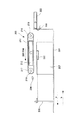
シート収納部200には、トレイ上に積載されているシートの後端位置を規制する端部規制部材としての後端規制部材205が矢印a,bで示すシート給送方向に移動可能に設けられている。また、シートのシート給送方向に対して直交する方向(以下、幅方向という)の位置を規制する幅方向規制部材206,207が矢印c,dで示す幅方向に移動可能に設けられている。
The
そして、このような後端規制部材205及び幅方向規制部材206,207を設けることにより、トレイ上に複数のサイズのシートを積載収納できるようになっている。なお、後端規制部材205と幅方向規制部材206,207は、トレイ201の昇降動作と干渉しないようにトレイ201に形成された開口部208a〜210にそれぞれ移動可能に配置されている。
By providing such a rear
シート給送部208は、図3に示すように、トレイ上の最上位のシートを吸引するためのシート吸引ダクト212と、シート吸引ダクト212によって吸引されたシートを吸着して搬送する複数の無端状ベルトである搬送ベルト213を備えている。なお、シート吸引ダクト212は幅方向に設けられ、枠部材202の上端部に不図示の支持部材を介して固定されている。
As shown in FIG. 3, the
搬送ベルト213は、シート吸引ダクト212を挟んで配置されている駆動ローラ216と従動ローラ217に吸引ダクト212を覆うようにして、等間隔で巻き掛けられている。なお、駆動ローラ及び従動ローラ216,217の各ローラ軸218,219は枠部材202に対して不図示の支持部材を介して平行に、且つ回転可能に取り付けられている。
The conveying
吸引ダクト212の各搬送ベルト213に対応する部分には不図示のエア吸引用の開口が形成され、搬送ベルト213の全周には多数のエア吸引穴220が形成されている。また、シート吸引ダクト212には不図示のエアフロー源(ポンプまたはファン等)が接続されている。
An air suction opening (not shown) is formed in a portion corresponding to each
そして、エアフロー源を駆動させた状態で不図示のシャッタを開くとシート吸引ダクト212内は真空状態になり、吸引力が生ずる。これにより、各搬送ベルト213に対応する開口、エア吸引穴220を介して搬送ベルト213の下方のエアが吸引され、シートレベル検知センサ203に検知されるレベルにある最上位のシートが搬送ベルト213に真空吸着される。
When the shutter (not shown) is opened while the airflow source is driven, the inside of the
枠部材202のシート給紙方向下流側の側壁面には、図2に示すようにシート束の先端部に分離エアを吹き付けるための先端分離ダクト223が設けられている。また、枠部材202の幅方向の両側壁面の幅方向規制部材206,207の近傍には、図4に示すようにシート束の側端にエアを吹き付けるためのサイド分離ダクト221,222が前奥それぞれ対向するように配置されている。
On the side wall surface of the
なお、この先端分離ダクト223及びサイド分離ダクト221,222においても、同一の不図示のエアフロー源(ファン)が接続されており、不図示のシャッタの開閉動作によってダクト内に図2及び図4の矢印で示すエアフローが生ずるようになっている。
The
また、これら先端分離ダクト223とサイド分離ダクト221,222の開口は最上位のシートSがシート吸引ダクト212によって吸引される高さ位置周辺にそれぞれ設けられている。
Further, the openings of the leading
このような位置に開口を設けることにより、シート給送時、図5に示すように最上位のシートS1と最上位から2枚目のシートS2の間に効率的に空気流を発生させることができる。これにより、確実にシートを捌くことができ、最上位シートS1とすぐ下に位置する2枚目のシートS2との間の分離性を向上させることができる。 By providing an opening at such a position, an air flow can be efficiently generated between the uppermost sheet S1 and the second sheet S2 from the uppermost position as shown in FIG. it can. Accordingly, it is possible to reliably roll the sheets, and it is possible to improve the separation between the uppermost sheet S1 and the second sheet S2 positioned immediately below.
図5、図6では最上位のシートS1がシート吸引ダクト212の吸引力と先端分離ダクト223、サイド分離ダクト221,222のシート分離力によって搬送ベルト213に真空吸着された状態を示している。
5 and 6 show a state in which the uppermost sheet S1 is vacuum-sucked to the
このように搬送ベルト213に真空吸着されたとき、シート吸引ダクト212はトレイ201上のシート給送方向先端寄りに配置されているので、最上位のシートS1は先端付近で搬送ベルト213に真空吸着される。したがって、シート吸引ダクト212によって吸引されない後端部は、図5に示すように搬送ベルト213の吸引位置に対して、やや下方向に垂れ下がった形となる。
In this way, when the sheet is sucked by the conveying
なお、図5に示すように、後端規制部材205には、シートレベル検知センサ203に検知されるレベルに上昇した最上位のシートS1の後端側が浮上しないようシートS1の後端部を押える後端押え部材226が設置されている。また、図6に示すように、幅方向規制部材206,207には、シートレベル検知センサ203に検知されるレベルに上昇した最上位のシートS1の幅方向の両側が浮上しないようシートS1の両側端部を押えるサイド押え部材224,225が設置されている。
As shown in FIG. 5, the trailing
これにより、先端分離ダクト223、サイド分離ダクト221,222のシート分離力により、最上位のシートS1が浮上してもシートS1の両側端部はサイド押え部材224,225に、シートS1の後端部は後端押え部材226により押えられる。
Thus, even if the uppermost sheet S1 is lifted by the sheet separating forces of the leading
従って、最上位シートS1の幅方向の中央部のみが2枚目のシートS2から分離して搬送ベルト213に真空吸着される際、最上位のシートS1と2枚目のシートS2との間には空隙部が形成される。
Therefore, when only the central portion in the width direction of the uppermost sheet S1 is separated from the second sheet S2 and vacuum-adsorbed to the
そして、この空隙部には、先端分離ダクト223とサイド分離ダクト221,222からのエアが吹き込まれる。これにより、空隙部を流れるエアが最上位のシートS1と2枚目のシートS2の間を流れ、両サイドと後端部が塞がれた略ポケット形状を形成しつつ、後端押え部材226とサイド押え部材224,225の間の領域をエアが抜けていくことになる。この結果、最上位のシートS1と2枚目のシートS2とを、シート先端からシート後端まで確実に分離することができる。
Then, air from the
なお、最上位のシートS1のシート先端に上向き又は下向きの折れやカールがある場合でも、シートS1の幅方向の両側部がサイド押え部材224,225によって押えられているので、カールは矯正される。このため、略ポケット形状はシート先端に開口する形状となる。
Even when the top end of the uppermost sheet S1 has an upward or downward fold or curl, both sides in the width direction of the sheet S1 are pressed by the
ところで、このように搬送ベルト213にシートSを真空吸着した後、搬送ベルト213を図5に示す矢印B方向に駆動すると、最上位のシートS1は下流へ搬送される。この際、図7の(a)及び(b)に示すように、後端押え部材226の下面を滑りながらシートS1は移動する。
By the way, after the sheet S is vacuum-sucked on the conveying
この時、後端押え部材226とシートS1又はシートS2の間に発生する動摩擦μp、シートS1とシートS2との間に発生する動摩擦μs、搬送ベルトの搬送力F、後端押え部材の質量Nの関係は、下記に示すようになる必要がある。
At this time, the dynamic friction μp generated between the trailing
F>μp・N>μs・N F> μp · N> μs · N
ここで、μp・N<μs・Nの関係になると、最上位のシートS1が搬送ベルト213に真空吸着されて搬送されると、シートS1に連られて、図7(c)に示すように、2枚目のS2も一緒に下流へ搬送されてしまい重送を起こす可能性が高くなる。
Here, when the relationship of μp · N <μs · N is satisfied, when the uppermost sheet S1 is vacuum-sucked and conveyed by the
μp・N>μs・Nであれば、最上位のシートS1が搬送ベルト213により搬送されても、2枚目のシートS2は後端押え部材226との摩擦抵抗で一緒に連れられて搬送されることはなく、重送の発生を抑えることができる。
If μp · N> μs · N, even if the uppermost sheet S1 is conveyed by the conveying
したがって、このような重送の発生を抑えるため、後端押え部材226の表面を表面性の粗いシート同士の摩擦力μmax(通常0.55〜0.6程度)を少なくとも上回るように設定している。
Therefore, in order to suppress the occurrence of such double feeding, the surface of the rear
この後端押え部材226のシートS1との接触面となる後端押え部材226の下面には、後述する図9に示す抵抗部材229が取り付けられている。なお、本実施の形態においては、シートSの後端規制部材205から離れる方向の移動を規制するため、このような抵抗部材229として、表面性が毛羽立ったブラシ状のものを、毛目方向が給送方向に対して逆目になるように取り付けている。これ以外にも、後端押え部材226の下面に、ゴム材やその他粘性部材のような表面抵抗のあるものを取り付けるようにしても良い。
A
一方、シートS1は、両側部をサイド押え部材224,225の下面を擦りながら移動するが、シートを円滑に移動させるためには、少くともサイド押え部材224,225の下面は平滑面になっており、かつ帯電しにくくなっていることが必要である。
On the other hand, the sheet S1 moves while rubbing the lower surfaces of the
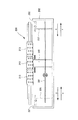
次に、後端規制部材205及び本発明の要部である解除機構について図8〜図10を用いて説明する。なお、図8は、後端規制部材205の斜視図、図9はその側面図、図10は解除機構の構成を示す図である。
Next, the rear
図8及び図9に示すように、後端規制部材205は、積載時のシートSの後端面と当接してシートをガイドする当接面を構成する後端規制ガイド227を備えている。なお、当接面を構成する後端規制ガイド227の表面は、シート吸引ダクト212によって吸着されるシートSが上昇する際、接触抵抗が少なくなるよう複数のリブ227aが形成されている。
As shown in FIGS. 8 and 9, the trailing
また、後端規制部材205は、矢印a,bに示すシート給送方向に移動した後、後端規制部材205を固定するため、図10に示すような保持部である移動規制ストッパ228を上下方向に移動可能に備えている。
Further, the rear
この移動規制ストッパ228は、複数のサイズに対応するため枠部材底部に設けた不図示のレール歯型と係脱自在に噛み合う歯型部228aを底部に備えている。そして、この移動規制ストッパ228を上下移動させることにより、後端規制部材205のトレイ201に対する移動及び固定が可能となっている。
The
なお、238は、移動規制ストッパ228が下端に設けられた移動規制ストッパ支台である。この移動規制ストッパ支台238は、移動規制ストッパ228の歯型部228aを枠部材底部に設けたレール歯型と確実に噛み合わせるよう底部引っ張りバネ237によって下方向へ付勢されている。
さらに、後端規制部材205は、既述したように積載された最上位のシートS1の後端部を上面から押えるための後端押え部材226を備えている。なお、本実施の形態において、後端押え部材226は、図8に示すように幅方向に2つに分割されており、これら後端押え部材226a,226bは、後端規制ガイド227の当接面と反対側の裏面に配された後端押えスライダ230により接続されている。また、これら2つ後端押え部材226a,226bの下面には、それぞれ既述した抵抗部材229が取り付けられている。
Further, the rear
後端押えスライダ230は、後端規制ガイド227の裏面に形成された上下方向に延びたガイド溝227bに沿って上下方向にスライド可能に設けられている。そして、後端押えスライダ230を上下方向にスライドさせると、後端規制ガイド227の当接面に沿って後端押え部材226a,226bを上下移動させることができ、後端押え部材226a,226bの高さ位置を変更させることができる。
The rear
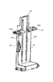
図10において、231は軸231cを支点として後端規制部材205に回動自在に設けられた操作部である操作ノブである。この操作ノブ231は、移動規制ストッパ228の歯型部228aの係止解除動作と、後端押えスライダ230を介して後端押え部材226a,226bを上方へ持ち上げる退避動作を行うためのものである。
In FIG. 10,
この操作ノブ231は、平歯ギア部231aを備えており、平歯ギア部231aはアイドラギア232〜235を介して後端押えスライダ230の底面に下方より当接している昇降ラック236に連結されている。
The
なお、平歯ギア部231a、アイドラギア232〜235、昇降ラック236及び後端押えスライダ230により、操作ノブ231により後端押え部材226a,226bを収納されたシートよりも上方に上昇させる第2の解除機構205Bが構成される。
In addition, the second release which raises the rear
一方、操作ノブ231の上方曲げ部231bは、底部引っ張りバネ237によって下方向へ付勢されている移動規制ストッパ支台238に設けられた当接部238aに下方から接触している。なお、操作ノブ231の上方曲げ部231b、当接部238a及び底部引っ張りバネ237により、操作ノブ231の操作に連動して移動規制ストッパ228を係止解除方向に移動させる第1の解除機構205Aが構成される。
On the other hand, the
これにより、図11に示すように操作ノブ231を、例えば指で握って矢印D方向に押し込む操作を行うと、平歯ギア部231aによって昇降ラック236が矢印Fに示すように上昇し、これに伴い後端押えスライダ230が上昇する。これにより、後端押え部材226a,226bが上昇し、図12に示すようにトレイ201に収納されたシートSの上面よりも上方に移動する。
Accordingly, as shown in FIG. 11, when the
また、同時に操作ノブ231の上方曲げ部231bにより移動規制ストッパ支台238と一体に移動規制ストッパ228が図11に示す係止解除方向である矢印G方向に上昇し、移動規制ストッパ部228の歯型部228aがレール歯型から離間する。
At the same time, the
つまり、本実施の形態においては、操作ノブ231を矢印D方向に押し込むと、図12に示すように移動規制ストッパ228の保持が解除され、後端規制部材205がシート給送方向に移動可能な状態となる。また同時に、後端押え部材226a,226bが上昇し、最上位のシートS1の上面から十分離れた位置へ上昇する。これにより、移動規制ストッパ228の移動の際に、後端押え部材226a,226bが図13に示すようにシートSの積載端面に干渉するのを防ぐことができる。
That is, in the present embodiment, when the
なお、この後、操作ノブ231から指を離すと、昇降ラック236及び移動規制ストッパ支台238の荷重で操作ノブ231が矢印Dと逆方向に回動する。この結果、昇降ラック236は下降するが、その途中で後端押え部材226a,226bは、図14に示すように最上位のシートS1に上方から当接するので、確実に上方からシートSの後端部を押えることができる。
After that, when the finger is released from the
また、このように移動規制ストッパ228が最上位のシートS1に上方から当接した後、移動規制ストッパ支台238が下降し、移動規制ストッパ228の歯型部228aが枠部材底部に設けたレール歯型と噛み合うようになる。
Further, after the
このように、後端規制部材205を移動する際、操作ノブ231を操作することにより、移動規制ストッパ228を係止解除方向に移動させ、かつ後端押え部材226a,226bをトレイ201に収納されたシートSよりも上方に上昇させることができる。これにより、シート積載時の操作性が向上する。また、シート積載後に必要なセット動作の誤操作を防ぐことができ、さらにシートの積載上限高さを上げることが可能となるので、積載容量を大きくすることができる。
Thus, when the rear
さらに、後端押え部材226a,226bによりシートを押えることにより、気温、湿度等の使用環境により発生するシートのカールに影響されることなく、またシートの厚み、表面性、剛体差等幅広い物性のシートを安定して給送することができる。
Furthermore, by pressing the sheet with the rear
なお、本実施の形態においては、操作ノブ231からのギア列と梃作用によって後端規制部材226a,226b及び移動規制ストッパ228を昇降させているが、ワイヤー、ソレノイド、小型モータ等の電子部品等を使用しても同等の効果を得ることができる。
In this embodiment, the rear
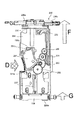
また、これまでの説明においては、後端押え部材226は、上下方向にのみ移動するものとして説明したが、本発明は、これに限らない。例えば、図15の(a)に示すように、操作ノブ231の操作により、後端押え部材226を後端規制ガイド227の上端まで上昇させた後、さらに図15の(b)〜(d)に示すように、その位置で180度回動させるようにしても良い。
In the above description, the rear
このように後端押え部材226を後端規制ガイド227の上端で180度回動させることにより、後端押え部材226をトレイ201の上方から退避させることができ、これによりシートをトレイ201へ上方から積載することができるようになる。この結果、シートの積載性が向上する。
Thus, by rotating the trailing
なお、図15においては、後端押え部材226を後端規制ガイド227(後端規制部材205)の上端で180度回動させるようにしたが、後端押え部材226を90度以上、上方回動させるようにすれば、同様の効果を得ることができる。
In FIG. 15, the rear
また、本実施の形態の説明では、本発明をシートの後端の位置を規制するための後端規制部材に適用した場合について説明したが、本発明はこれに限定されるものではない。例えば、シートの側端(シート給送方向と交差する方向の端部)を規制する幅方向規制部材に設けられているサイド押え部材224,225に本発明を適用してもよい。
In the description of the present embodiment, the case where the present invention is applied to the rear end regulating member for regulating the position of the rear end of the sheet has been described, but the present invention is not limited to this. For example, the present invention may be applied to the
さらに、これまでの説明においては、本発明に係るシート給送装置を、通常の画像形成装置に適用した場合について説明したが、本発明は、これに限らない。例えば、1枚ずつ給送されたシートに対して所定の処理(例えば、穿孔、折り、表面処理、製本、その他シート加工全般)を行うシート処理装置を備えた画像形成装置についても適用することができる。さらに、この画像形成装置に設けられたシート処理装置に、本発明に係るシート給送装置を設けても良い。 In the above description, the sheet feeding apparatus according to the present invention is applied to a normal image forming apparatus. However, the present invention is not limited to this. For example, the present invention can also be applied to an image forming apparatus including a sheet processing apparatus that performs predetermined processing (for example, punching, folding, surface processing, bookbinding, and other sheet processing in general) on sheets fed one by one. it can. Furthermore, the sheet feeding apparatus according to the present invention may be provided in the sheet processing apparatus provided in the image forming apparatus.
100 カラーレーザプリンタ
100B 画像形成部
200 シート収納部
201 トレイ
202 枠部材
205 後端規制部材(端部規制部材)
205A 第1の解除機構
205B 第2の解除機構
208 シート給送部
211 シート給送装置
213 搬送ベルト
226 後端押え部材
227 後端規制ガイド
228 移動規制ストッパ
229 抵抗部材
230 後端押えスライダ
231 操作ノブ
238 移動規制ストッパ支台
S シート
DESCRIPTION OF
205A
Claims (7)
前記シート収納部にシート給送方向に移動自在に設けられ、前記シート収納部に収納されたシートの端部位置を規制する端部規制部材と、
前記端部規制部材に移動自在に設けられ、底部に前記シート収納部に設けられたレール歯型に噛み合う歯型部を有し、前記歯型部が前記レール歯型に上下から係脱自在に係止して前記端部規制部材をシートサイズに応じた端部規制位置に保持する保持部と、
前記端部規制部材に上下方向に移動自在に設けられ、前記端部規制部材により端部位置が規制されたシートの端部の上面に上方から当接して押える端部押え部材と、
前記端部規制部材を移動する際に、前記保持部による前記端部規制部材の係止を解除させると共に前記端部押え部材をシートの端部の上面から上方に移動させる解除機構と、を備え、
前記解除機構は、前記端部規制部材におけるシートの端部が当接する当接面の側方に配置された1つの操作部と、前記操作部の操作に連動して前記保持部による前記端部規制部材の係止を解除させる第1の解除機構と、前記端部押え部材をシートの端部の上面から上方に移動させる第2の解除機構と、有し、前記操作部の操作により、前記第1の解除機構により前記保持部の前記歯型部が前記レール歯型から離間して前記端部規制部材の係止を解除すると共に、前記第2の解除機構により前記端部押え部材をシートの端部の上面から上方に移動させることを特徴とするシート給送装置。 In a sheet feeding device that feeds a sheet stored in a sheet storage unit,
An end regulating member that is movably provided in the sheet feeding direction in the sheet storage unit and regulates an end position of a sheet stored in the sheet storage unit;
Movably provided on the end portion regulating member has a tooth die portion meshing with the rail teeth type provided in the sheet storage portion to the bottom portion, the tooth-shaped portion is vertical or al-engaged freely on the rail-toothed A holding part that holds the end part restricting member in an end part restricting position according to a sheet size.
An end pressing member that is provided on the end regulating member so as to be movable in the vertical direction, and that abuts and presses against the upper surface of the end of the sheet whose end position is regulated by the end regulating member;
A release mechanism for releasing the engagement of the end regulating member by the holding portion and moving the end pressing member upward from the upper surface of the end portion of the sheet when moving the end regulating member. ,
The release mechanism includes one operation portion disposed on a side of a contact surface with which an end portion of the sheet contacts in the end restriction member, and the end portion by the holding portion in conjunction with the operation of the operation portion. A first release mechanism for releasing the locking of the restricting member; and a second release mechanism for moving the end pressing member upward from the upper surface of the end portion of the sheet. The first mold release mechanism causes the tooth mold portion of the holding portion to move away from the rail tooth mold to release the end portion restricting member, and the second release mechanism moves the end retainer member to the sheet. A sheet feeding device, wherein the sheet feeding device is moved upward from the upper surface of the end portion of the sheet.
Priority Applications (2)
| Application Number | Priority Date | Filing Date | Title |
|---|---|---|---|
| JP2006280658A JP4777211B2 (en) | 2006-10-13 | 2006-10-13 | Sheet feeding apparatus and image forming apparatus |
| US11/870,152 US7540489B2 (en) | 2006-10-13 | 2007-10-10 | Sheet feeding device and image forming apparatus |
Applications Claiming Priority (1)
| Application Number | Priority Date | Filing Date | Title |
|---|---|---|---|
| JP2006280658A JP4777211B2 (en) | 2006-10-13 | 2006-10-13 | Sheet feeding apparatus and image forming apparatus |
Publications (2)
| Publication Number | Publication Date |
|---|---|
| JP2008094594A JP2008094594A (en) | 2008-04-24 |
| JP4777211B2 true JP4777211B2 (en) | 2011-09-21 |
Family
ID=39302412
Family Applications (1)
| Application Number | Title | Priority Date | Filing Date |
|---|---|---|---|
| JP2006280658A Expired - Fee Related JP4777211B2 (en) | 2006-10-13 | 2006-10-13 | Sheet feeding apparatus and image forming apparatus |
Country Status (2)
| Country | Link |
|---|---|
| US (1) | US7540489B2 (en) |
| JP (1) | JP4777211B2 (en) |
Families Citing this family (18)
| Publication number | Priority date | Publication date | Assignee | Title |
|---|---|---|---|---|
| JP4717685B2 (en) * | 2006-04-03 | 2011-07-06 | キヤノン株式会社 | Sheet feeding apparatus and image forming apparatus |
| JP4835489B2 (en) * | 2007-03-28 | 2011-12-14 | コニカミノルタビジネステクノロジーズ株式会社 | Paper feeding device and image forming apparatus |
| JP5366574B2 (en) * | 2008-10-09 | 2013-12-11 | キヤノン株式会社 | Sheet feeding apparatus and image forming apparatus |
| US8419008B2 (en) * | 2009-01-30 | 2013-04-16 | Canon Kabushiki Kaisha | Image forming apparatus |
| JP2010269857A (en) * | 2009-05-19 | 2010-12-02 | Canon Inc | Sheet feeder, and image forming device having the same |
| US8262080B2 (en) * | 2010-01-13 | 2012-09-11 | Canon Kabushiki Kaisha | Sheet feeding apparatus and image forming apparatus |
| GB201001814D0 (en) * | 2010-02-04 | 2010-03-24 | Vivid Laminating Technologies | Feed mechanism for laminating machine |
| US8210519B2 (en) | 2010-05-17 | 2012-07-03 | Canon Kabushiki Kaisha | Sheet feeding apparatus and image forming apparatus |
| US8262081B2 (en) * | 2010-09-14 | 2012-09-11 | Xerox Corporation | Trail edge guide deflector for improved media feeding |
| JP5578064B2 (en) * | 2010-12-22 | 2014-08-27 | コニカミノルタ株式会社 | Paper feeding device and image forming system |
| JP5885427B2 (en) * | 2011-08-24 | 2016-03-15 | キヤノン株式会社 | Sheet feeding apparatus and image forming apparatus |
| JP5854766B2 (en) * | 2011-11-01 | 2016-02-09 | キヤノン株式会社 | Sheet feeding apparatus and image forming apparatus |
| JP6355393B2 (en) | 2014-04-04 | 2018-07-11 | キヤノン株式会社 | Sheet feeding apparatus and image forming apparatus |
| JP6413603B2 (en) | 2014-10-15 | 2018-10-31 | 株式会社リコー | Sheet feeding apparatus, image forming apparatus, and image forming system |
| CN105742242A (en) * | 2014-12-26 | 2016-07-06 | 株式会社理光 | Sheet separating method for circuit substrates, and sheet separating device for circuit substrates |
| JP2020152523A (en) * | 2019-03-20 | 2020-09-24 | 株式会社リコー | Sheet separating device and image forming device |
| JP2022047244A (en) * | 2020-09-11 | 2022-03-24 | 富士フイルムビジネスイノベーション株式会社 | Feeding device and use device of sheet-like medium |
| JP2022166715A (en) * | 2021-04-21 | 2022-11-02 | 株式会社リコー | Sheet transport device and image formation system |
Family Cites Families (24)
| Publication number | Priority date | Publication date | Assignee | Title |
|---|---|---|---|---|
| JPH03121541U (en) * | 1990-03-19 | 1991-12-12 | ||
| JPH03284546A (en) * | 1990-03-30 | 1991-12-16 | Minolta Camera Co Ltd | Paper feed tray device |
| US5135213A (en) * | 1990-10-15 | 1992-08-04 | Xerox Corporation | Apparatus for method for high speed sheet feeding |
| JPH05178483A (en) | 1991-12-27 | 1993-07-20 | Matsushita Electric Ind Co Ltd | Automatic paper sheet feeding device |
| US5247337A (en) * | 1992-06-18 | 1993-09-21 | Xerox Corporation | Method and apparatus for copy sheet feed timed imaging registration system |
| JPH0680261A (en) * | 1992-09-03 | 1994-03-22 | Sharp Corp | Paper feeding device |
| JP3349360B2 (en) * | 1996-09-13 | 2002-11-25 | シャープ株式会社 | Paper feeder |
| JP3667007B2 (en) * | 1996-10-30 | 2005-07-06 | キヤノン株式会社 | Sheet feeding apparatus and image forming apparatus |
| JP2000203737A (en) * | 1999-01-13 | 2000-07-25 | Fuji Xerox Co Ltd | Paper feeder and image forming device provided with the same |
| JP3366597B2 (en) * | 1999-08-06 | 2003-01-14 | 京セラミタ株式会社 | Paper trailing edge regulating member |
| JP2001187642A (en) * | 1999-11-26 | 2001-07-10 | Kyocera Corp | Sheet feeder cassette |
| JP2002302279A (en) * | 2001-04-06 | 2002-10-18 | Seiko Epson Corp | Feeder having multifeed prevention roller |
| JP2004083246A (en) * | 2002-08-28 | 2004-03-18 | Oki Data Corp | Sheet feeder |
| US7380779B2 (en) * | 2003-10-16 | 2008-06-03 | Canon Kabushiki Kaisha | Sheet processing system |
| JP4185843B2 (en) * | 2003-10-16 | 2008-11-26 | キヤノン株式会社 | Sheet processing system |
| JP3862084B2 (en) * | 2003-10-30 | 2006-12-27 | ホリゾン・インターナショナル株式会社 | Booklet reversing device |
| JP4541906B2 (en) * | 2004-01-27 | 2010-09-08 | キヤノン株式会社 | Sheet bundle back folding unit flat processing apparatus, sheet processing apparatus, and image forming apparatus |
| JP2006008260A (en) * | 2004-06-22 | 2006-01-12 | Konica Minolta Business Technologies Inc | Paper feeder, and image forming device having the same |
| JP4143578B2 (en) * | 2004-07-20 | 2008-09-03 | キヤノン株式会社 | Sheet processing apparatus and image forming apparatus having the same |
| JP4429219B2 (en) * | 2004-07-20 | 2010-03-10 | キヤノン株式会社 | Sheet processing apparatus and image forming apparatus provided with the apparatus |
| JP4262159B2 (en) * | 2004-07-20 | 2009-05-13 | キヤノン株式会社 | Sheet processing apparatus and image forming apparatus having the same |
| JP4663571B2 (en) * | 2005-06-10 | 2011-04-06 | キヤノン株式会社 | Sheet stacking apparatus, sheet processing apparatus, and image forming apparatus |
| US7434796B2 (en) * | 2005-08-11 | 2008-10-14 | Canon Kabushiki Kaisha | Sheet processing apparatus and image forming apparatus using sheet processing apparatus |
| US7703758B2 (en) * | 2005-08-31 | 2010-04-27 | Canon Kabushiki Kaisha | Sheet stacking device and sheet processing device, and image forming apparatus provided therewith |
-
2006
- 2006-10-13 JP JP2006280658A patent/JP4777211B2/en not_active Expired - Fee Related
-
2007
- 2007-10-10 US US11/870,152 patent/US7540489B2/en not_active Expired - Fee Related
Also Published As
| Publication number | Publication date |
|---|---|
| US20080088078A1 (en) | 2008-04-17 |
| JP2008094594A (en) | 2008-04-24 |
| US7540489B2 (en) | 2009-06-02 |
Similar Documents
| Publication | Publication Date | Title |
|---|---|---|
| JP4777211B2 (en) | Sheet feeding apparatus and image forming apparatus | |
| US9434561B2 (en) | Sheet stacking device, sheet feeding device and image forming apparatus | |
| US9004484B2 (en) | Sheet-medium conveying device and image forming apparatus | |
| JP2007137559A (en) | Paper feeding device | |
| JP2010013208A (en) | Paper feeder and image forming device | |
| JP5815589B2 (en) | Recording medium feeding unit and image forming apparatus having the same | |
| JP2009173397A (en) | Paper feeding device and image formation device having the same | |
| JP5094982B2 (en) | Medium conveying apparatus and image forming apparatus | |
| US8218194B2 (en) | Medium transporting apparatus and image forming apparatus that employs the medium transporting apparatus | |
| JP5521461B2 (en) | Recording medium supply apparatus and image forming apparatus | |
| US7823871B2 (en) | Sheet feeding apparatus, housing incorporating the same and image forming apparatus | |
| JP2007030995A (en) | Recorded medium feeding tray, paper feeding device and image forming device | |
| JP6272083B2 (en) | Sheet feeding apparatus and image forming apparatus | |
| JP4877512B2 (en) | Mounting member for sheet storage device, sheet storage device, and image forming apparatus | |
| JP5968106B2 (en) | Sheet conveying apparatus and image forming apparatus | |
| US8613439B2 (en) | Sheet feeding apparatus and image forming apparatus | |
| US8540230B2 (en) | Sheet feeding apparatus and image forming apparatus with curvature formation portion and reversely rotatable feeding roller | |
| JP7188112B2 (en) | Feeding device and image forming device | |
| JP6750335B2 (en) | Sheet stacking apparatus and image forming apparatus | |
| JP6729038B2 (en) | Sheet stacking apparatus and image forming apparatus | |
| JP2023091406A (en) | Sheet feeding device and image forming device | |
| JP2006089248A (en) | Paper feed cassette | |
| JP2009173375A (en) | Paper conveying device and image forming device having the same | |
| JP2024126144A (en) | SHEET FEEDING DEVICE AND IMAGE FORMING APPARATUS | |
| JP2022162665A (en) | Sheet feeder and image formation apparatus |
Legal Events
| Date | Code | Title | Description |
|---|---|---|---|
| A621 | Written request for application examination |
Free format text: JAPANESE INTERMEDIATE CODE: A621 Effective date: 20091008 |
|
| A977 | Report on retrieval |
Free format text: JAPANESE INTERMEDIATE CODE: A971007 Effective date: 20110324 |
|
| A131 | Notification of reasons for refusal |
Free format text: JAPANESE INTERMEDIATE CODE: A131 Effective date: 20110405 |
|
| A521 | Request for written amendment filed |
Free format text: JAPANESE INTERMEDIATE CODE: A523 Effective date: 20110602 |
|
| TRDD | Decision of grant or rejection written | ||
| A01 | Written decision to grant a patent or to grant a registration (utility model) |
Free format text: JAPANESE INTERMEDIATE CODE: A01 Effective date: 20110628 |
|
| A01 | Written decision to grant a patent or to grant a registration (utility model) |
Free format text: JAPANESE INTERMEDIATE CODE: A01 |
|
| A61 | First payment of annual fees (during grant procedure) |
Free format text: JAPANESE INTERMEDIATE CODE: A61 Effective date: 20110629 |
|
| R150 | Certificate of patent or registration of utility model |
Ref document number: 4777211 Country of ref document: JP Free format text: JAPANESE INTERMEDIATE CODE: R150 Free format text: JAPANESE INTERMEDIATE CODE: R150 |
|
| FPAY | Renewal fee payment (event date is renewal date of database) |
Free format text: PAYMENT UNTIL: 20140708 Year of fee payment: 3 |
|
| LAPS | Cancellation because of no payment of annual fees |