JP6355393B2 - Sheet feeding apparatus and image forming apparatus - Google Patents
Sheet feeding apparatus and image forming apparatus Download PDFInfo
- Publication number
- JP6355393B2 JP6355393B2 JP2014077862A JP2014077862A JP6355393B2 JP 6355393 B2 JP6355393 B2 JP 6355393B2 JP 2014077862 A JP2014077862 A JP 2014077862A JP 2014077862 A JP2014077862 A JP 2014077862A JP 6355393 B2 JP6355393 B2 JP 6355393B2
- Authority
- JP
- Japan
- Prior art keywords
- sheet
- sheet feeding
- detection
- height
- feeding apparatus
- Prior art date
- Legal status (The legal status is an assumption and is not a legal conclusion. Google has not performed a legal analysis and makes no representation as to the accuracy of the status listed.)
- Active
Links
Images


Classifications
-
- B—PERFORMING OPERATIONS; TRANSPORTING
- B65—CONVEYING; PACKING; STORING; HANDLING THIN OR FILAMENTARY MATERIAL
- B65H—HANDLING THIN OR FILAMENTARY MATERIAL, e.g. SHEETS, WEBS, CABLES
- B65H1/00—Supports or magazines for piles from which articles are to be separated
- B65H1/08—Supports or magazines for piles from which articles are to be separated with means for advancing the articles to present the articles to the separating device
- B65H1/14—Supports or magazines for piles from which articles are to be separated with means for advancing the articles to present the articles to the separating device comprising positively-acting mechanical devices
-
- B—PERFORMING OPERATIONS; TRANSPORTING
- B65—CONVEYING; PACKING; STORING; HANDLING THIN OR FILAMENTARY MATERIAL
- B65H—HANDLING THIN OR FILAMENTARY MATERIAL, e.g. SHEETS, WEBS, CABLES
- B65H1/00—Supports or magazines for piles from which articles are to be separated
- B65H1/08—Supports or magazines for piles from which articles are to be separated with means for advancing the articles to present the articles to the separating device
- B65H1/18—Supports or magazines for piles from which articles are to be separated with means for advancing the articles to present the articles to the separating device controlled by height of pile
-
- B—PERFORMING OPERATIONS; TRANSPORTING
- B65—CONVEYING; PACKING; STORING; HANDLING THIN OR FILAMENTARY MATERIAL
- B65H—HANDLING THIN OR FILAMENTARY MATERIAL, e.g. SHEETS, WEBS, CABLES
- B65H1/00—Supports or magazines for piles from which articles are to be separated
- B65H1/08—Supports or magazines for piles from which articles are to be separated with means for advancing the articles to present the articles to the separating device
- B65H1/24—Supports or magazines for piles from which articles are to be separated with means for advancing the articles to present the articles to the separating device with means for relieving or controlling pressure of the pile
-
- B—PERFORMING OPERATIONS; TRANSPORTING
- B65—CONVEYING; PACKING; STORING; HANDLING THIN OR FILAMENTARY MATERIAL
- B65H—HANDLING THIN OR FILAMENTARY MATERIAL, e.g. SHEETS, WEBS, CABLES
- B65H1/00—Supports or magazines for piles from which articles are to be separated
- B65H1/26—Supports or magazines for piles from which articles are to be separated with auxiliary supports to facilitate introduction or renewal of the pile
- B65H1/266—Support fully or partially removable from the handling machine, e.g. cassette, drawer
-
- B—PERFORMING OPERATIONS; TRANSPORTING
- B65—CONVEYING; PACKING; STORING; HANDLING THIN OR FILAMENTARY MATERIAL
- B65H—HANDLING THIN OR FILAMENTARY MATERIAL, e.g. SHEETS, WEBS, CABLES
- B65H3/00—Separating articles from piles
- B65H3/02—Separating articles from piles using friction forces between articles and separator
- B65H3/06—Rollers or like rotary separators
- B65H3/0669—Driving devices therefor
-
- B—PERFORMING OPERATIONS; TRANSPORTING
- B65—CONVEYING; PACKING; STORING; HANDLING THIN OR FILAMENTARY MATERIAL
- B65H—HANDLING THIN OR FILAMENTARY MATERIAL, e.g. SHEETS, WEBS, CABLES
- B65H3/00—Separating articles from piles
- B65H3/02—Separating articles from piles using friction forces between articles and separator
- B65H3/06—Rollers or like rotary separators
- B65H3/0684—Rollers or like rotary separators on moving support, e.g. pivoting, for bringing the roller or like rotary separator into contact with the pile
-
- B—PERFORMING OPERATIONS; TRANSPORTING
- B65—CONVEYING; PACKING; STORING; HANDLING THIN OR FILAMENTARY MATERIAL
- B65H—HANDLING THIN OR FILAMENTARY MATERIAL, e.g. SHEETS, WEBS, CABLES
- B65H7/00—Controlling article feeding, separating, pile-advancing, or associated apparatus, to take account of incorrect feeding, absence of articles, or presence of faulty articles
- B65H7/02—Controlling article feeding, separating, pile-advancing, or associated apparatus, to take account of incorrect feeding, absence of articles, or presence of faulty articles by feelers or detectors
- B65H7/04—Controlling article feeding, separating, pile-advancing, or associated apparatus, to take account of incorrect feeding, absence of articles, or presence of faulty articles by feelers or detectors responsive to absence of articles, e.g. exhaustion of pile
-
- B—PERFORMING OPERATIONS; TRANSPORTING
- B65—CONVEYING; PACKING; STORING; HANDLING THIN OR FILAMENTARY MATERIAL
- B65H—HANDLING THIN OR FILAMENTARY MATERIAL, e.g. SHEETS, WEBS, CABLES
- B65H7/00—Controlling article feeding, separating, pile-advancing, or associated apparatus, to take account of incorrect feeding, absence of articles, or presence of faulty articles
- B65H7/20—Controlling associated apparatus
-
- B—PERFORMING OPERATIONS; TRANSPORTING
- B65—CONVEYING; PACKING; STORING; HANDLING THIN OR FILAMENTARY MATERIAL
- B65H—HANDLING THIN OR FILAMENTARY MATERIAL, e.g. SHEETS, WEBS, CABLES
- B65H2404/00—Parts for transporting or guiding the handled material
- B65H2404/10—Rollers
- B65H2404/14—Roller pairs
- B65H2404/142—Roller pairs arranged on movable frame
- B65H2404/1421—Roller pairs arranged on movable frame rotating, pivoting or oscillating around an axis, e.g. parallel to the roller axis
- B65H2404/14211—Roller pairs arranged on movable frame rotating, pivoting or oscillating around an axis, e.g. parallel to the roller axis the axis being one the roller axis, i.e. orbiting roller
-
- B—PERFORMING OPERATIONS; TRANSPORTING
- B65—CONVEYING; PACKING; STORING; HANDLING THIN OR FILAMENTARY MATERIAL
- B65H—HANDLING THIN OR FILAMENTARY MATERIAL, e.g. SHEETS, WEBS, CABLES
- B65H2405/00—Parts for holding the handled material
- B65H2405/10—Cassettes, holders, bins, decks, trays, supports or magazines for sheets stacked substantially horizontally
- B65H2405/15—Large capacity supports arrangements
-
- B—PERFORMING OPERATIONS; TRANSPORTING
- B65—CONVEYING; PACKING; STORING; HANDLING THIN OR FILAMENTARY MATERIAL
- B65H—HANDLING THIN OR FILAMENTARY MATERIAL, e.g. SHEETS, WEBS, CABLES
- B65H2511/00—Dimensions; Position; Numbers; Identification; Occurrences
- B65H2511/50—Occurence
- B65H2511/515—Absence
-
- B—PERFORMING OPERATIONS; TRANSPORTING
- B65—CONVEYING; PACKING; STORING; HANDLING THIN OR FILAMENTARY MATERIAL
- B65H—HANDLING THIN OR FILAMENTARY MATERIAL, e.g. SHEETS, WEBS, CABLES
- B65H2513/00—Dynamic entities; Timing aspects
- B65H2513/40—Movement
-
- B—PERFORMING OPERATIONS; TRANSPORTING
- B65—CONVEYING; PACKING; STORING; HANDLING THIN OR FILAMENTARY MATERIAL
- B65H—HANDLING THIN OR FILAMENTARY MATERIAL, e.g. SHEETS, WEBS, CABLES
- B65H2553/00—Sensing or detecting means
- B65H2553/40—Sensing or detecting means using optical, e.g. photographic, elements
- B65H2553/41—Photoelectric detectors
- B65H2553/412—Photoelectric detectors in barrier arrangements, i.e. emitter facing a receptor element
-
- B—PERFORMING OPERATIONS; TRANSPORTING
- B65—CONVEYING; PACKING; STORING; HANDLING THIN OR FILAMENTARY MATERIAL
- B65H—HANDLING THIN OR FILAMENTARY MATERIAL, e.g. SHEETS, WEBS, CABLES
- B65H2553/00—Sensing or detecting means
- B65H2553/60—Details of intermediate means between the sensing means and the element to be sensed
- B65H2553/61—Mechanical means, e.g. contact arms
-
- B—PERFORMING OPERATIONS; TRANSPORTING
- B65—CONVEYING; PACKING; STORING; HANDLING THIN OR FILAMENTARY MATERIAL
- B65H—HANDLING THIN OR FILAMENTARY MATERIAL, e.g. SHEETS, WEBS, CABLES
- B65H2553/00—Sensing or detecting means
- B65H2553/80—Arangement of the sensing means
-
- B—PERFORMING OPERATIONS; TRANSPORTING
- B65—CONVEYING; PACKING; STORING; HANDLING THIN OR FILAMENTARY MATERIAL
- B65H—HANDLING THIN OR FILAMENTARY MATERIAL, e.g. SHEETS, WEBS, CABLES
- B65H2701/00—Handled material; Storage means
- B65H2701/10—Handled articles or webs
- B65H2701/11—Dimensional aspect of article or web
- B65H2701/112—Section geometry
- B65H2701/1125—Section geometry variable thickness
-
- B—PERFORMING OPERATIONS; TRANSPORTING
- B65—CONVEYING; PACKING; STORING; HANDLING THIN OR FILAMENTARY MATERIAL
- B65H—HANDLING THIN OR FILAMENTARY MATERIAL, e.g. SHEETS, WEBS, CABLES
- B65H2801/00—Application field
- B65H2801/03—Image reproduction devices
- B65H2801/06—Office-type machines, e.g. photocopiers
Landscapes
- Engineering & Computer Science (AREA)
- Mechanical Engineering (AREA)
- Sheets, Magazines, And Separation Thereof (AREA)
- Controlling Sheets Or Webs (AREA)
Description
本発明は、封筒等の厚さが不均一のシートを給送可能なシート給送装置及び画像形成装置に関する。 The present invention relates to a sheet feeding apparatus and an image forming apparatus capable of feeding a non-uniform thickness sheet such as an envelope.
複写機、ファクシミリ装置、プリンタ、複合機等の画像形成装置は、シート積載部に積載したシートを1枚ずつ分離して画像形成部に向けて送り出すシート給送装置を備えている。近年、オンデマンドデジタル印刷の市場拡大に伴い、従来の定型サイズのカットシート以外にも、多種多様なシートへの印刷ニーズが増大している。 2. Description of the Related Art Image forming apparatuses such as copying machines, facsimile machines, printers, and multifunction machines include a sheet feeding device that separates sheets stacked on a sheet stacking unit one by one and sends them to the image forming unit. In recent years, with the expansion of the on-demand digital printing market, there is an increasing need for printing on a wide variety of sheets other than the conventional standard size cut sheets.
例えば、画像形成装置により、封筒や、文字や絵柄をシートの凹凸部上に装飾したようなエンボスシートに印刷する場合や、予め部分的にトナー像やインクを印刷したシートに対して再び印刷するプレプリントなどがある。封筒の場合には、宛名書き印刷等を行うために画像形成装置のシート積載部に多数の封筒を積載したときに、封筒の袋部の重ね合わせ貼り部分や折り返し等のフラップ部によりシート厚さが部分的に異なるため、封筒束の厚さに部分的に大きな差が生じる。また、部分的にエンボス加工が施されたシートの場合や予め部分的に厚くトナー像やインクを印刷したシートをプレプリントする場合にも、封筒のシート積載部へのセット時と同様に、シート束の厚さに部分的に大きな差が生じる場合がある。 For example, when printing on an envelope, an embossed sheet in which characters and patterns are decorated on the uneven portion of the sheet, or printing again on a sheet on which a toner image or ink has been partially printed. There are preprints. In the case of envelopes, when a large number of envelopes are stacked on the sheet stacking portion of the image forming apparatus for address printing or the like, the sheet thickness is increased by the overlapped portion of the bag portion of the envelope or the flap portion such as folding. Since these are partially different, there is a large difference in the thickness of the envelope bundle. Also, in the case of a partially embossed sheet or when preprinting a sheet that has been partially printed with a toner image or ink in advance, the sheet is the same as when the envelope is set on the sheet stacking portion. There may be some large differences in bundle thickness.
このように部分的にシートの厚さが異なるシートを、シート積載部に多数枚積載して1枚ずつ給送する場合に、積載されたシート束の上面に高低差が生じてしまう。そして、このシート束の上面の高低差によって、シートを給送するための給送ローラと最上位のシートとの当接圧(給紙圧)が均等でなくなる。この当接圧が不均等な状態で給送ローラによりシートを送り出すと、シートの斜め搬送や重送といったシート給送不良を引き起こすおそれがある。そこで、シート束が積載される給送トレイに、部分的にシートを底上げする部材を設けることで、積載されたシート束の上面の高低差を低減することが可能な給紙カセットが提案されている(特許文献1参照)。 Thus, when a large number of sheets having partially different sheet thicknesses are stacked on the sheet stacking unit and fed one by one, a difference in height occurs on the upper surface of the stacked sheet bundle. Due to the height difference of the upper surface of the sheet bundle, the contact pressure (sheet feeding pressure) between the feeding roller for feeding the sheet and the uppermost sheet is not uniform. If the sheet is fed by the feeding roller in a state where the contact pressure is not uniform, there is a risk of causing a sheet feeding failure such as oblique conveyance or double feeding of the sheet. Therefore, a paper feed cassette has been proposed that can reduce the height difference of the upper surface of the stacked sheet bundle by providing a member that partially raises the sheet to the feeding tray on which the sheet bundle is stacked. (See Patent Document 1).
しかし、特許文献1の構成によると、封筒等のシートの厚さが不均一なシートを給紙カセットから円滑に給送することが可能になるものの、給紙カセットでは一度の補給で給送できるシートの枚数が250枚〜500枚程度である。 However, according to the configuration of Patent Document 1, it is possible to smoothly feed a sheet with a non-uniform thickness such as an envelope from the sheet cassette, but the sheet cassette can be fed with a single replenishment. The number of sheets is about 250 to 500.
近年の、高速で大量のシートを連続的に給送して印刷するというニーズに応えるために、シートを積載するシート積載部を水平状態で昇降させるためのリフタ機構を設け、最上位のシートを順次送り出す大容量のシート給送装置が採用されてきている。この大容量のシート給送装置では、1000枚〜数千枚のシートを一度にシート積載部に補給して大量のシートを連続的に給送が可能である。このシート給送装置では、積載されているシートの上面が給送ローラ等のシート給送手段により給送可能な高さに維持されるように、シート高さ検知センサによるシートの上面の検知に基づいてリフタ機構がシート積載部を上昇させる。 In order to respond to the recent need for continuous feeding and printing of a large number of sheets at high speed, a lifter mechanism is provided to raise and lower the sheet stacking section for stacking sheets in a horizontal state, A large-capacity sheet feeding apparatus that sequentially feeds has been adopted. In this large capacity sheet feeding apparatus, it is possible to continuously feed a large number of sheets by supplying 1000 to thousands of sheets to the sheet stacking unit at a time. In this sheet feeding apparatus, a sheet height detection sensor detects the upper surface of a sheet so that the upper surface of the stacked sheets is maintained at a height that can be fed by sheet feeding means such as a feeding roller. Based on this, the lifter mechanism raises the sheet stacking unit.
しかし、封筒やエンボスシート等のような厚さが不均一なシートをシート積載部に積載したときに、封筒のフラップ部やシートの厚い部分がシート給送方向の下流側に位置するように積載されて給送される場合がある。この場合には、積載されたシート束の上面が、シート給送方向における下流側が高く上流側が低くなる。特に、大容量のシート給送装置ではシートの積載枚数が多いため、積載されたシート上面のシート給送方向における下流側と上流側の高低差が大きくなる。一方、シート給送装置では、シートの上面を検知するためのシート高さ検知センサがシート給送方向の下流に配置され、シートの有無を検知するためのシート有無検知センサがシート高さ検知センサの上流に配置されている構成のものがある。 However, when sheets with non-uniform thickness, such as envelopes and embossed sheets, are stacked on the sheet stacking unit, the envelope flaps and the thick part of the sheet are stacked so that they are located downstream in the sheet feeding direction. May be sent. In this case, the upper surface of the stacked sheet bundle is higher on the downstream side in the sheet feeding direction and lower on the upstream side. In particular, since a large-capacity sheet feeding apparatus has a large number of stacked sheets, the height difference between the downstream side and the upstream side in the sheet feeding direction on the upper surface of the stacked sheets becomes large. On the other hand, in the sheet feeding apparatus, a sheet height detection sensor for detecting the upper surface of the sheet is disposed downstream in the sheet feeding direction, and the sheet presence / absence detection sensor for detecting the presence / absence of the sheet is a sheet height detection sensor. There is a thing of the structure arrange | positioned upstream.
このように各検知センサが配置されているシート給送装置において、積載されているシートの上面の高低差が大きいシートを連続的に給送している時に、シートがまだシート積載部に積載されているにも拘わらず「シート無し」と誤検知されてしまう場合がある。これは、積載されているシート束の上面がシート給送方向で下流側よりも上流側が大きく下がっている場合に生じる。 In the sheet feeding apparatus in which each detection sensor is arranged in this way, when a sheet having a large difference in height of the upper surface of the stacked sheet is continuously fed, the sheet is still stacked on the sheet stacking unit. In spite of this, it may be erroneously detected as “no sheet”. This occurs when the upper surface of the stacked sheet bundle is significantly lower in the sheet feeding direction on the upstream side than on the downstream side.
下流に配置されているシート高さ検知センサの検知に基づきシートの上面が給送可能な高さに維持された状態で、シート上面の上流側が下流側より大きく下がっていると、上流に配置されているシート有無検知センサがシート上面を検知できない場合が生じる。そのため、制御部は、このシート有無検知センサからの信号に基づいて、「シート無し」と誤判断してしまう。これにより、シートがシート積載部に積載されているのにも拘らずシートの給送動作が停止されてしまうという問題が生じる。 If the upstream side of the upper surface of the sheet is greatly lowered from the downstream side while the upper surface of the sheet is maintained at a feedable height based on the detection by the sheet height detection sensor disposed downstream, the upstream side of the sheet is disposed upstream. In some cases, the sheet presence / absence detection sensor that is present cannot detect the upper surface of the sheet. Therefore, the control unit erroneously determines “no sheet” based on the signal from the sheet presence / absence detection sensor. This causes a problem that the sheet feeding operation is stopped despite the sheets being stacked on the sheet stacking unit.
本発明は、大容量のシート給送装置に、カットシートと同様に封筒、エンボスシート等の厚さが不均一なシートを多数枚積載して連続して円滑な給送を可能にするシート給送装置及び画像形成装置を提供することを目的とする。 The present invention is a sheet feeding device that enables continuous and smooth feeding by stacking a large number of sheets having non-uniform thicknesses such as envelopes and embossed sheets as in the case of cut sheets on a sheet feeding device. An object is to provide a feeding device and an image forming apparatus.
本発明は、シート給送装置において、シートが積載されるシート積載手段と、前記シート積載手段を昇降させる昇降手段と、前記シート積載手段に積載されたシートの最上位のシートに当接して給送する給送手段と、前記シート積載手段に積載されたシートの最上位のシートの位置を検知するシート高さ検知手段と、前記シート積載手段に積載されているシートの有無を検知するシート有無検知手段であって、前記シート高さ検知手段によるシート検知位置よりもシート給送方向上流においてシートと当接するシート有無検知部材と、前記シート有無検知部材の移動に基づく信号を出力するシート有無検知センサと、を備えるシート有無検知手段と、前記シート積載手段の高さ方向の位置を検知する位置検知手段と、を備え、前記昇降手段は、前記シート高さ検知手段の検知に基づいて、前記シート積載手段を上昇させて最上位シートの位置が所定の範囲内に維持されるように制御手段により制御され、前記制御手段は、最上位シートの位置が前記所定の範囲内にある場合、かつ、前記位置検知手段の検知に基づき前記シート積載手段の位置が所定高さよりも上にある場合には前記シート有無検知手段の信号に基づく所定の制御を行い、最上位シートの位置が前記所定の範囲内にある場合、かつ、前記位置検知手段の検知に基づき前記シート積載手段の位置が所定高さよりも下にある場合には前記所定の制御を行わないことを特徴とする。 In the sheet feeding device, the sheet stacking unit for stacking sheets, an elevating unit for moving the sheet stacking unit up and down, and an uppermost sheet stacked on the sheet stacking unit are in contact with the sheet stacking unit. and feeding means for feeding, sheet presence detecting the sheet height detection means for detecting the position of the top sheet, the presence or absence of sheets stacked on said sheet stacking means of sheets stacked on said sheet stacking means a detecting means, the sheet and outputting the sheet presence detecting member and Oite sheet in contact with the upstream sheet feeding than the sheet detection position by the sheet height detection means, a signal based on movement of the sheet presence detecting member comprising a presence detection sensor, and the sheet presence detecting means and a position detecting means for detecting the position in the height direction of said sheet stacking means, wherein the lifting means Based on the detection of the sheet height detection means, said sheet stacking means to raise the the position of the uppermost sheet is controlled by the control means so as to be maintained within a predetermined range, the control means, the uppermost sheet If the position of is within the predetermined range, and, when the position of said sheet stacking means based on detection of the position detecting means is above the predetermined height of the predetermined based on the signal of the sheet presence detecting means there line control, if the position of the uppermost sheet is within the predetermined range, and the position of said sheet stacking means based on detection of the position detecting means in some cases below the predetermined height of the predetermined It is characterized by not performing control .
本発明によると、大容量のシート給送装置において、一般に使われる厚さの均一なカットシートと同様に封筒、エンボスシート等の厚さの不均一なシートを多数枚積載して連続して円滑な給送を可能にする。 According to the present invention, in a large-capacity sheet feeding apparatus, a large number of non-uniform thickness sheets such as envelopes and embossed sheets are stacked in a continuous and smooth manner as well as generally used uniform thickness cut sheets. To enable efficient feeding.
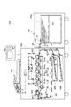
以下、本発明に係る実施形態を、図面に基づき詳細に説明する。図1は、本発明の実施形態に係る画像形成装置の構成を示す断面図である。 DESCRIPTION OF EMBODIMENTS Hereinafter, embodiments according to the present invention will be described in detail with reference to the drawings. FIG. 1 is a cross-sectional view illustrating a configuration of an image forming apparatus according to an embodiment of the present invention.
[画像形成装置]
図1に示すように、画像形成装置600は、画像形成装置本体(以下、装置本体という)600aと、装置本体600aに接続された給紙デッキ100とを備えている。シート給送装置としての給紙デッキ100は、装置本体600aの図1の右側方に接続されている。
[Image forming apparatus]
As shown in FIG. 1, the
装置本体600aは、通常のシートSを積載する給紙カセット909a,909b、電子写真プロセスを用いてシート上にトナー像を形成する画像形成部603、及びシートSに形成されたトナー像を定着させる定着装置904等を備える。画像形成部603は、シート給送装置としての給紙デッキ100から給送されるシートSに画像を形成する。また、装置本体600aの上部には、原稿読み取り部及び原稿搬送部を有する原稿読取装置650と、ユーザ等が装置本体600aに対して各種の入力及び設定を行うための操作部601とが配置されている。
The apparatus
画像形成装置600では、原稿の画像をシートに形成する際に、まず、原稿読取装置650の原稿搬送部により搬送された原稿の画像を、原稿読み取り部のイメージセンサで読み取る。この後、読み取られたデジタルデータを露光手段に入力し、このデジタルデータに応じた光を、画像形成部603に設けられた感光ドラム914a,914b,914c,914dに夫々照射する。このように光が照射されると、各感光ドラム表面に静電潜像が形成され、この静電潜像を現像することにより、感光ドラム表面にイエロー(Y)、マゼンタ(M)、シアン(C)、ブラック(Bk)の各色トナー像が形成される。
In the
次に、上記4色のトナー像を、給紙カセット909a,909bに対応する給送ローラ908または給紙デッキ100に対応する、給送手段としての給送ローラ101により送り出されて搬送ベルト903で搬送されてくるシート上に転写する。さらに、この転写後、シート上に転写されたトナー像を、定着装置904によって加熱定着する。
Next, the four color toner images are sent out by the
上記のようにトナー像をシート上に定着した後、シート片面に画像を形成する片面モードが選択されていれば、そのままシートSを排出ローラ対907を介して機外に排出する。一方、シート両面に画像を形成する両面モードが選択されていれば、シートSを定着装置904から反転ローラ905に受け渡した後、所定のタイミングで反転ローラ905を反転させる。そして、シートSを両面搬送ローラ906a,906b,906c,906d,906e,906fの方向へ搬送する。この後、再度、シートSを画像形成部603に搬送し、その裏面にイエロー、マゼンタ、シアン、ブラックの4色のトナー像を転写する。このように裏面に4色のトナー像が転写されたシートSは、定着装置904に再度搬送されてトナー像を定着された後、排出ローラ対907から機外に排出される。
After fixing the toner image on the sheet as described above, if the single-side mode for forming an image on one side of the sheet is selected, the sheet S is directly discharged outside the apparatus via the
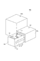
ここで、図2を参照して、給紙デッキ100の詳細について説明する。なお、図2は、給紙デッキ100を示す断面図である。
Here, the details of the
図2に示すように、給紙デッキ100は、装置本体600aの給紙カセット909a,909bのシートSの積載量よりも、より多数枚のシートSをリフタトレイ107上に積載して、連続給送することが可能な大容量積載型のシート給送装置である。給紙デッキ100は、デッキ本体100aを有している。デッキ本体100a内には、積載されたシートを1枚ずつ給送するシート給送部を有している。
As shown in FIG. 2, the
シート給送部は、多数枚のシートSを収容するための箱状の収納庫106と、収納庫106内に昇降可能に配置されてシートSが積載されるリフタトレイ107と、シートを給送する給送ローラ101とを有している。シート積載手段としてのリフタトレイ107を昇降する昇降機構(リフタ機構)130は、リフタトレイ107を吊り下げて支持するワイヤ130aを有する。さらに、昇降手段としての昇降機構130は、ワイヤ130aが懸け回される複数のプーリ130bと、ワイヤ130aが連結されたワイヤプーリ130cと、ワイヤプーリ130cが接続されたリフタモータM3と、を有する。そして、リフタモータM3(図4参照)がワイヤプーリ130cを回転させてワイヤ130aを巻き付けることにより、リフタトレイ107が上昇する。給送ローラ101は、リフタトレイ107に積載されたシートSのシート給送方向下流に対向する上方に設けられ、リフタトレイ107に積載されているシートSを送り出す。
The sheet feeding unit feeds the sheet, a box-shaped
さらに、シート給送部は、送り出されたシートSを更に下流に送るためのフィードローラ102と、このフィードローラ102に対向するように配置され、シートSを1枚ずつ分離するリタードローラ103とを有している。フィードローラ102及びリタードローラ103で分離搬送されたシートSは、引き抜きローラ対104,105によって装置本体600aに搬送される。なお、上記の各ローラは、外周面がゴム等の高い摩擦係数の部材で巻かれたゴムローラとして構成されている。
Further, the sheet feeding unit includes a
例えば、給送ローラ101で2枚以上のシートSが送り出され、フィードローラ102とリタードローラ103との分離ニップ部に挟まれると、2枚目以降のシートSの進入をリタードローラ103により阻止する。そして、1枚目の最上位シートのみを引き抜きローラ対104,105側へ搬送する。
For example, when two or more sheets S are sent out by the
給送ローラ101の近傍には、シート高さ検知センサ202が配置されている。また、給送ローラ101のシート給送方向における上流には、シート有無検知センサ201が配置されている。さらに、引き抜きローラ対104,105とフィードローラ102間には給送センサ203が配置されている。リタードローラ103の下方には、位置検知センサ205が配置され、収納庫106の下部にはトレイ下限センサ204が配置されている。
A sheet
[画像形成装置の制御系]
次に、図3を参照して、画像形成装置600の制御系について説明する。なお、図3は、画像形成装置600の制御系を示すブロック図である。
[Control system of image forming apparatus]
Next, a control system of the
図3に示すように、画像形成装置600の装置本体600a内にはCPU回路部630が設けられている。CPU回路部630は、CPU629と、制御プログラム等を格納したROM631と、制御データを一時的に保持するための領域や制御に伴う演算の作業領域として用いられるRAM660とを有している。
As shown in FIG. 3, a
画像形成装置600は、外部インターフェース637によって外部PC(コンピュータ)620を接続されている。外部インターフェース637は、外部PC620からのプリントデータを受信すると、このデータをビットマップ画像に展開し、画像データとして画像信号制御部634へ出力する。
The
画像信号制御部634は、この画像データをプリンタ制御部635へ出力する。プリンタ制御部635は、画像信号制御部634からのデータを不図示の露光制御部へ出力する。なお、イメージリーダ制御部633から画像信号制御部634へは、イメージセンサで読み取った原稿の画像が出力され、画像信号制御部634は、この画像出力をプリンタ制御部635へ出力する。
The image
操作部601は、画像形成に関する各種機能を設定するための複数のキー及び設定状態を表示するための表示部(モニター)等を有している。そして操作部601は、ユーザ等による各キーの操作に対応する信号をCPU回路部630に出力すると共に、CPU回路部630からの信号に基づき、対応する情報を表示部に表示する。
The
CPU回路部630は、ROM631に格納された制御プログラム及び操作部601の設定に従い、画像信号制御部634を制御すると共に、原稿給送装置制御部632を介して原稿読取装置650(図1参照)の原稿搬送部を制御する。CPU回路部630は、イメージリーダ制御部633を介して原稿読取装置650の原稿読み取り部を制御し、プリンタ制御部635を介して画像形成部603(図1参照)を制御すると共に、制御手段636を介して給紙デッキ100を制御する。
The
本実施形態において、シート給送装置を制御する制御手段636は、給紙デッキ100に搭載され、CPU回路部630のCPU629等との情報のやり取りを行うことにより給紙デッキ100の駆動制御を行う。しかし、制御手段636をCPU回路部630と一体的に装置本体600a側に配設して、装置本体600a側から直接に給紙デッキ100を制御するように構成してもよい。
In the present embodiment, a
次に、図4及び図5を参照して、制御手段636の構成について説明する。図4は、制御手段636のブロック図であり、図5は、給紙デッキ100から収納庫106を手前に引き出した状態を示す斜視図である。
Next, the configuration of the
図5に示すように、収納庫106は、給紙デッキ100のデッキ本体100aに設けられたスライドレール115によって矢印X方向(図1及び図2の紙面手前方向)に移動可能に支持されている。収納庫106内には、シートSの各側端部を夫々ガイドする、奥側サイド規制板113、前側サイド規制板114、後端規制板116が設けられている。これら規制板113,114,116はそれぞれ、セットするシートのサイズに応じて、各矢印方向に手動で移動可能となるように支持されている。
As shown in FIG. 5, the
給紙デッキ100へのシートの補充のし方について説明する。まず、収納庫106をデッキ本体100aから引き出し、シートSをリフタトレイ107(図2参照)上にセットし、各規制板113,114,116を、セットしたシートSの端部に合わせるように移動させる。そして、収納庫106を再びデッキ本体100a内に収納するように閉じると、これに伴って制御手段636がリフタモータM3(図4)を制御してリフタトレイ107を上昇させる。そして制御手段636は、リフタトレイ107上(シート積載手段上)の最上位シートが給送ローラ101で送り出されるための適正な高さになった時点でリフタモータM3を停止する。リフタモータM3の駆動及び停止は、後述するシート高さ検知センサ202によるシートの上面の位置に応じた信号に基づいて制御手段636が制御する。
A method of replenishing sheets to the
図4に示すように、給紙デッキ100における制御系は、制御手段636、CPU701、RAM702、ROM703、ネットワークインターフェース704、通信インターフェース706、及び給送制御部708を有している。CPU701、RAM702、ROM703と、ネットワークインターフェース704と、通信インターフェース706とは、バス707を介して接続されている。
As shown in FIG. 4, the control system in the
給送制御部708は、I/O705を介してCPU701、RAM702、ROM703、ネットワークインターフェース704及び通信インターフェース706に接続されている。給送制御部708には、給送モータM1、搬送モータM2、リフタモータM3、シート有無検知センサ201、シート高さ検知センサ202、給送センサ203、トレイ下限センサ204、及び位置検知センサ205が接続されている。
The
給送モータM1、搬送モータM2及びリフタモータM3は、制御手段636の制御に基づく給送制御部708により駆動制御される。シート有無検知センサ201、シート高さ検知センサ202、給送センサ203、トレイ下限センサ204及び位置検知センサ205は、各検知信号を、給送制御部708を介して制御手段636に送信する。
The feed motor M1, the transport motor M2, and the lifter motor M3 are driven and controlled by a
給送モータM1は、その駆動により給送ローラ101を回転させる。搬送モータM2は、その駆動によりフィードローラ102、及び引き抜きローラ対104,105等を回転させる。昇降機構130に設けられているリフタモータM3は、その駆動によりリフタトレイ107を昇降作動させる。
The feed motor M1 rotates the
ここで、図6は、図2に示した給紙デッキ100におけるシートを給送するためのシート給送部を示す斜視図であり、図7(a),(b)は、シート給送部の部分断面図である。
6 is a perspective view showing a sheet feeding unit for feeding sheets in the
図6及び図7に示すように、シート有無検知手段Eは、制御手段636に接続されたシート有無検知センサ201を有している。シート有無検知手段Eは更に、給送ローラ101のシート給送方向上流に配置され、リフタトレイ107上のシートSの上面に接触可能に設けられたシート有無検知レバー118を有している。シート有無検知レバー118がリフタトレイ107に積載されているシートの上面に当接することにより回動する。制御手段636は、シート有無検知レバー118の回動位置に応じてシート有無検知センサ201が発生する信号に基づいて、リフタトレイ107上に積載されるシートSの有無を検知する。なお、シート有無検知レバー118がリフタトレイ107に積載されているシートの上面に当接する位置は、給送ローラ101がシートの上面に当接する位置よりもシート給送方向において上流側に位置している。
As shown in FIGS. 6 and 7, the sheet presence / absence detection means E has a sheet presence /
シート高さ検知手段Hは、制御手段636に接続されたシート高さ検知センサ202と、給送ローラ101を支持する回動可能なローラアーム112及びローラアーム112に設けられている遮光板112aと、を有している。リフタトレイ107の昇降により、積載されているシートSに当接している給送ローラ101を介してローラアーム112が回転し、シート高さ検知センサ202がローラアーム112の回転位置に応じた信号を出力する。制御手段636は、シート高さ検知センサ202からの信号に基づいて、リフタトレイ107上に積載されるシート束の上面の高さが所定の高さにあるかを検知する。なお、このシート高さ検知手段Hは、給送ローラ101と積載されているシートの当接部の位置を検知して、その検知に基づいて制御手段636が昇降機構130を制御してリフタトレイ107を上昇させる。また、給送センサ203は、フィードローラ102と引き抜きローラ対104,105との間をシートSの先端及び後端の通過に応じて信号を出力する。
The sheet height detection unit H includes a sheet
なお、本実施の形態では、給送ローラ101の高さに応じてシート高さ検知センサ202が信号を出力するように構成されている。しかし、シートの上面に直接検知レバーを当接させ、その検知レバーの位置に応じてシート高さ検知センサが信号を出力するようにシート高さ検知手段Hを構成してもよい。
In this embodiment, the sheet
トレイ下限センサ204は、収納庫106の下方に配置され、リフタトレイ107の下限位置を規定するためのセンサであり、トレイ下限センサ204からの信号に基づき、制御手段636は、リフタトレイ107の下降を停止させる。
The tray
位置検知手段Pは、位置検知センサ205と、リフタトレイ107の位置及び積載されているシートの高さに応じて第1回動位置(図7(b)の位置)と第2回動位置(図7(a)の位置)に回動する位置検知レバー119と、を有している。そして、位置検知レバー119の回動位置に応じた信号を位置検知センサ205が出力する。
The position detection means P has a first rotation position (position of FIG. 7B) and a second rotation position (FIG. 7B) according to the position of the
図6に示すように、給送ローラ101は、フィードローラ102の軸に回動可能に取り付けられているローラアーム112に支持されている。ローラアーム112はフィードローラ102の回転軸102aを中心に矢印Y方向(図7(a)参照)に回動可能に支持され、回転軸102a周りに設けられたネジリコイルバネ117(図6参照)で常時下向きの方向(図7(a)の時計回り方向)に付勢される。ローラアーム112の端部には、シート高さ検知センサ202に対向してこのセンサ202の発光・受光部間の光を遮光、透光するための遮光板112aが設けられている。ローラアーム112はネジリコイルバネ117により給送ローラ101がリフタトレイ107上の最上位のシートSに当接するように付勢されているため、給送ローラは、リフタトレイ107に積載されているシートの上面の昇降に追従することができる。フィードローラ102とリタードローラ103は、給送モータM1からタイミングベルト108と平歯ギア109a,109b,109e,109dを介してそれぞれに回転を付与される。給送ローラ101は、フィードローラ102の回転軸から平歯ギア109fを介して回転を伝達されて、フィードローラ102と同方向に回転する。
As shown in FIG. 6, the
搬送ローラとしてのフィードローラ102は、給送ローラ101のシート給送方向下流に配置され、給送ローラ101により送り出されたシートSを、引き抜きローラ対104,105を介して装置本体600a側に搬送する。また、収納庫106の壁面の所定位置には、リフタトレイ107の昇降動作に応じて回動する位置検知レバー119の突出部119cを摺動可能に挿入する長穴部106aが形成されている。突出部119cは、この長穴部106aから収納庫106内に突出して、リフタトレイ107上のシート束の側端又はリフタトレイ107の側端に接触することができる。
A
図7(a),(b)に示すように、収納庫106の側方には、位置検知センサ205が配置され、これに対向する位置に位置検知レバー119が配置されている。位置検知センサ205及び位置検知レバー119は、デッキ本体100aに互いに所定の位置関係となるように支持されている。
As shown in FIGS. 7A and 7B, a
位置検知レバー119は、デッキ本体100aに固定された回動軸119aに回動可能となるように支持され、上部に当接突起119bを有し、収納庫106内に上記長穴部106aから突出可能な突出部119cを有している。位置検知センサ205は、リフタトレイ107の高さ方向の位置に伴って回動する位置検知レバー119の位置に応じた信号を出力する。
The
図9(a)は、リフタトレイ107上にシートSが多数枚セットされ、給送ローラ101によって送り出し可能な状態、もしくは、送り出し中の状態を示す図である。この場合、位置検知レバー119は、シート束の側端面により突出部119cを押されることで、回動軸119aを中心として同図の時計回り方向に回転し、位置検知センサ205の発光・受光部間の透過光を遮光する。これにより、制御手段636は、位置検知センサ205からの信号に基づき、リフタトレイ107上にシートSがあることを検知する。
FIG. 9A is a diagram illustrating a state in which a large number of sheets S are set on the
この状態から、最上位のシートSから順次、給送ローラ101によって送り出されていくと、積載されているシートSが少なくなっていくことに伴い、昇降機構130がリフタトレイ107を徐々に上昇させる。これにより、図9(b)に示すように、リフタトレイ107の下端部が位置検知レバー119を通過すると、位置検知レバー119は、突出部119cが自由状態になる。そして、位置検知レバー119は、回動軸119aを中心として同図の反時計回り方向に回転し、位置検知センサ205の発光・受光部間が透過状態になる。これにより、制御手段636は、位置検知センサ205からの信号に基づき、現状のリフタトレイ107の高さ位置が少なくとも位置検知レバー119よりも上方に位置することを検知する。
In this state, when the sheets S are sequentially fed from the uppermost sheet S by the feeding
ユーザがシートSをセットするために、図5に示すように収納庫106が手前に引き出された際に、リフタトレイ107が下降される(図9(c)の状態)。すなわち、収納庫106が引き出されると、昇降機構130が制御されて、積載されているシートの上面位置が位置検知レバー119を通過して位置検知センサ205が透過状態になる位置までリフタトレイ107を下降させる。この制御により、シート束がリフタトレイ107に補充される度に、補充されたシート束の上面が同じ位置になるようにリフタトレイ107が下降される。そのため、包装されたシートの1パックを一定の高さの位置のシート束上面に載せていくことができるため、シート束を収納庫106にセットする際の作業性を向上させることができる。そして、制御手段636は、シート束がセットされてリフタトレイ107が下降していく間に、トレイ下限センサ204からの信号を受けたときにリフタトレイ107を停止させる。このとき、リフタトレイ107上のシートSが満載状態である。
When the user sets the sheet S, the
シートSのセットが完了し、収納庫106をデッキ本体100a内に押し込んで装着すると、リフタトレイ107が上昇し、最上位シートがシート高さ検知センサ202で検知された時点で、リフタトレイ107の移動が停止する。この状態で、給送モータM1の回転駆動が、給送ローラ101、フィードローラ102及びリタードローラ103に伝達されることで、シートの給送が行われる。
When the setting of the sheet S is completed and the
図8(a)に示すように、最上位のシートSが給送ローラ101で順次送り出されて、最上位の高さが低くなっていくと、最上位のシートSに当接している給送ローラ101が下方に回動する。給送ローラ101が、シートの減少により下降すると、シート高さ検知センサ202に基づいて、最上位のシートSの高さが常にシートの給送が可能な範囲(一定範囲内に)に維持されるようにリフタトレイ107が上昇制御される。この制御については後で詳述する。
As shown in FIG. 8A, when the uppermost sheet S is sequentially sent out by the feeding
ここで、図12を参照して、給紙デッキ100のシート給送動作について説明する。なお、図12は、リフタトレイ107上のシート束の上面がシート給送可能な所定の高さに位置させるためのシート高さ確定処理のフローチャートを示す。
Here, a sheet feeding operation of the
制御手段636は、ステップS702で、シート高さ検知センサ202の検知信号を確認する。そして、ステップS703で、シート高さ検知センサ202の発光・受光部間では光が透過しているか否かを判断する。
In step S702, the
その結果、光が透過していると判断すれば、ステップS704で、リフタモータM3を駆動してリフタトレイ107を上昇させ、ステップS705で、シート高さ検知センサ202の発光・受光部間の光が遮光板112aで遮光されたか否かを判断する。その結果、光が遮光されたと判断すれば、ステップS706で、リフタモータM3の駆動を停止しリフタトレイ107を停止してシート高さが確定される。これにより、リフタトレイ107上のシート束の最上位の位置がシートを給送可能な位置になり、シート給送の準備が完了する(S707)。
As a result, if it is determined that light is transmitted, the lifter motor M3 is driven to raise the
そして、画像形成装置の本体制御手段からの給紙開始信号により、制御手段636がシート給送部を制御して、給送ローラ101を回転させてシートが送り出される。この動作に伴って、引き抜きローラ対104,105は、搬送モータM2(図4)の駆動をタイミングベルト111(図7(a))と平歯ギア110a〜110c(図7(a))を介して回転が伝達される。これにより、引き抜きローラ対104,105は、給送ローラ101で送り出されたシートSを装置本体600aに搬送する。
The
給送ローラ101、フィードローラ102、リタードローラ103により搬送されるシートは、駆動開始から予め設定されている時間内にそのシート先端及び後端が通過するか否かを、光軸の透過反射検知式の給送センサ203(図7(a)参照)で検知される。そして、シートSの端部が、所定の時間内で到達しない場合または通過しない場合に、給送センサ203からの信号が制御手段636に送られ、操作部601の表示部(モニター)にシート詰まり(ジャム)が表示される。
The sheet conveyed by the feeding
図7(a),(b)に示すように、シート有無検知センサ201は、最上位のシートSに当接可能な接触部118bを有し、給送ローラ101のシート給送方向上流側に配置されている。シート有無検知センサ201は、シート有無検知レバー118の回動軸118aを中心とした回動に応じて回動する遮光板118cで発光・受光部間の透過光を遮光又は透光されることに基づく信号が出力される。そして、この信号に基づいて制御手段636が、リフタトレイ107上のシートSの有無を検知する。
As shown in FIGS. 7A and 7B, the sheet presence /
シート有無検知レバー118は、デッキ本体(装置本体)100aに回動可能に支持された状態でその接触部(先端部)118bをリフタトレイ107上のシートSに接触することでシートSの有無を検知する。そして、シート有無検知レバー118は、リフタトレイ107上の最後のシートSが給送されたとき、リフタトレイ107の接触部118bに対向する位置に形成された穴部(不図示)に接触部118bが落ち込む。
The sheet presence /
これにより、シート有無検知レバー118は、回動軸118aを支点として図7の反時計回り方向に回動して遮光板118cがシート有無検知センサ201から離間する。つまり、リフタトレイ107上のシートSが無くなったとき、シート有無検知レバー118が回動軸118aを中心として反時計回り方向に回転し、遮光板118cがシート有無検知センサ201の発光・受光部間から離脱して光の透過状態とする。これによりシート有無検知センサ201から出力された信号を制御手段636が受けて、制御手段636がリフタトレイ107上のシートが無いことを検知する。
As a result, the sheet presence /
このように、シート有無検知センサ201が、制御手段636が最上位シートの有無を検知(判断)するための信号を出力すると、この信号を受信した制御手段636により、操作部601の表示部に「シート無し」を表示させる。そして制御手段636は、シート給送部によるシートの給送動作を停止させる。さらに、画像信号制御部634(図3)により作像処理(画像形成処理)を停止させる。
As described above, when the sheet presence /
ここで、給紙デッキ100には、定型カットシートの他に、折り返し用のフラップが付いた封筒や、表面に凹凸のあるエンボスシートや、タブ付シート、予め印字されたプレプリントシート等、多種多様なシート類をセットし給送することが可能である。
Here, in addition to the standard cut sheet, the
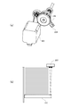
例えば、図10に示す封筒120を揃えてリフタトレイ107上に多数枚積み上げると、以下のようになる。封筒120の折り返しフラップ120bの領域と袋部120aの高さが異なっているため、封筒120の積載束における折り返しフラップ120bの高さL2と袋部120aの高さL1との関係は、L2>L1となる。これは、積み上げる封筒120の枚数が多くなるほど、比例的にL1とL2の高低差が大きくなり、リフタトレイ107上にセットした状態では、給送される最上位のシートの面が傾いてしまう。
For example, when a large number of
ここで、図11(a)は、封筒120を、フラップ120bがシート給送方向の下流側に位置するようにして、給紙デッキ100のリフタトレイ107上にセットした状態を示す断面図である。図11(a)に示すように、多数枚積載した封筒120の最上面は、上流側が下降する方向に傾いて傾斜した状態になる。また、シートの上面位置を所定の高さにするためのシート高さ検知手段Hが検知するシートの位置が給送ローラ101とシートとの当接部であり、この当接部よりもシート有無検知レバー118のシートとの当接部が上流側に配置されている。
Here, FIG. 11A is a cross-sectional view showing a state where the
このため上記検知センサ202で検知して停止した状態では、通常は最上位の封筒120に当接するはずの上記検知レバー118は封筒120の高さが傾斜している分上流側が低くなることで、接触部118bを最上位の封筒120に当接できない場合が生じる。この場合には、シート有無検知センサ201は遮光板118cが発光・受光部間の光軸から離れるため、制御手段636にシート無しの検知信号を出力してしまう。そして、制御手段636は、シート有無検知センサ201からの信号に基づいて、封筒120がリフタトレイ107上に積載されているにも拘わらず、操作部601の表示部に「シート無し」の表示をさせてしまうと同時に、封筒120の給送を停止させてしまう。
For this reason, in the state detected and stopped by the
そこで、本実施形態では、封筒120、表面に凹凸のあるエンボスシート、タブ付シートや、予め印字されたプレプリントシート等、多種多様なシート類をリフタトレイ107上に積載して給送する際に、位置検知センサ205の検知信号を利用する。即ち図11(b)のようにリフタトレイ107の位置が位置検知センサ205の検知位置の高さと同レベルの位置(Wの位置)より上方に位置する時は、制御手段636が上記検知センサ201の信号を受付けて操作部601の表示部にシートの有無を表示させる。つまり、位置検知センサ205の発光・受光部間が透過状態のときは、制御手段636が、シート有無検知センサ201の光の透過状態の信号により操作部601の表示部に「シート無し」を表示させる。
Therefore, in the present embodiment, when a wide variety of sheets such as an
図11(a)に示すように、シートが積載されているリフタトレイ107の位置がWの位置より下方に位置するとき、つまり、位置検知センサ205が遮光状態にあるときは、制御手段636は以下のようにする。即ち、制御手段636は、シート有無検知センサ201の光の透過状態の信号を受けても操作部601の表示部に「シート無し」の表示をさせない。さらに、制御手段636はシートの給送動作を停止させない。なお、位置検知センサ205が遮光状態にあるときは、制御手段636はシート有無検知センサ201からの信号を受け付けないようにしてもよい。
As shown in FIG. 11A, when the position of the
即ち、シートを連続的に給送している状態において、制御手段636は、シートの上面の低下に伴いリフタモータM3を作動させて、給送ローラ101と最上位シートとの位置関係を一定に維持するように制御する。その際、制御手段636は、位置検知センサ205の検知に基づくリフタトレイ107の高さ位置が所定高さ(Wの位置)を超えてから、シート有無検知センサ201の信号に基づいて操作部601の表示部に「シート無し」の表示を行わせる。つまり、制御手段636は、位置検知センサ205の検知に基づきリフタトレイ107の高さ位置が所定高さ(Wの位置)よりも高くなったときに、シート有無検知センサ201の信号に基づいて操作部601の表示部に「シート無し」の表示が行えるようにする。また、制御手段636は、位置検知センサ205の検知に基づきリフタトレイ107の高さ位置が所定高さ(Wの位置)よりも低いときには、操作部601の表示部には「シート有り」の表示を行う。
That is, in the state where the sheets are continuously fed, the
所定高さ(Wの位置)は、上記検知センサ201がシート上面の位置を検知可能な位置であり、封筒等のシート束上面の傾斜により、シート有無検知センサ201のシート有無検知レバー118が必ずシート束上面に当接できるような位置に設定されている。これは実験等により設定される。すなわち、所定高さ(Wの位置)よりも高い位置にトレイ107が位置する状態では、シート束の積載枚数が満載状態よりも大幅に少ないため、シート束の上面の傾斜が小さく、さらにシート束が少なくなるに連れてシート束の上面の傾斜も小さくなる。そこで、シート有無検知レバー118がシートの上面に当接することができる最も低い高さよりも高い位置に所定高さ(Wの位置)を設定すればよい。また、所定高さ(Wの位置)よりもリフタトレイ107が低い場合には、シートが必ず積載されているため、シートの有無を検知する必要がない。
The predetermined height (W position) is a position where the
なお、本実施形態では、シートの補充時に用いられる位置検知センサ205によりリフタトレイ107の高さ位置を検知し、その検知結果に基づいて制御手段636が「シート無し」の表示の可否を選択している。しかし、この構成に限らず、位置検知センサ205による高さ位置検知の代わりに専用のセンサを所定高さ(W点)に配置して、その専用のセンサの検知に基づいて「シート無し」の表示の可否を選択するように構成することも可能である。
In the present embodiment, the height detection position of the
また、所定高さ(Wの位置)に関しては、シート高さ検知センサ202とシート有無検知センサ201の配置間隔によっても決定される。つまり、シート高さ検知センサ202とシート有無検知センサ201との配置間隔が広いほど、検知位置の高低差(図14のα1とα2の距離)が大きくなるためWの位置を上に設定し、より積載枚数の少ない位置でシート有無検知センサ201を確認する。また、シート高さ検知センサ202とシート有無検知センサ201との配置間隔が狭いほど、上記と逆に、Wの位置を下方に設定する。ここで、リフタトレイ107上での最下位シートの有無を正確に検知するためには、Wの位置をより上方に設定することが望ましい。
The predetermined height (W position) is also determined by the arrangement interval between the sheet
ここで、図13を参照して、上述した給紙デッキ100におけるシート有無検知について説明する。
Here, the sheet presence / absence detection in the
即ち、図13に示すように、制御手段636は、シートの有無を確定するシート有無確定処理を実行するために、ステップS711で、トレイの高さ位置を検知するために位置検知センサ205の検知信号を確認する。そして、ステップS712で、位置検知センサ205の発光・受光部間で光が透過しているか否かを判断する。
That is, as shown in FIG. 13, the control means 636 detects the
その結果、光が透過していると判断すれば、図11に示すWの位置よりもリフタトレイ107が上に位置していることを示し、ステップS713で、シート有無検知センサ201の検知信号を確認するフローに移行する。ステップS714の判断フローで、シート有無検知センサ201の発光・受光部間で光が透過しているか否かを判断する。その結果、光が透過していると判断すれば、ステップS715でシート無しの確定判断を行い、ステップS716で操作部601の表示部に「シート無し(紙無し)」の表示を実行して終了する。
As a result, if it is determined that light is transmitted, it indicates that the
一方、ステップS712で位置検知センサ205の発光・受光部間では光が透過していない、つまり遮光と検出した場合、もしくはステップS714でシート有無検知センサ201の発光・受光部間では光が透過していないと検出した場合には、次のようになる。即ち、この場合は、まだリフタトレイ107上にシートが有ることを示しており、以下のように処理する。ステップS717で、シートの有りを確定し、ステップS718で、シート給送前であればシートの給送の準備が完了したとし、シートの給送中であればシートの給送を継続する。
On the other hand, light is not transmitted between the light emitting / receiving portions of the
以上、封筒120のセット時の事例を挙げて説明した。しかし、エンボスシートや、プレプリントシート、穴抜きシート等でもシート表面の凹凸や、トナー層、インク層、穴抜きの端部バリ等により、リフタトレイ107上に多数枚積載した場合は、封筒と同様に、最上位のシート上面が傾いてしまう。しかし、本実施形態によれば、封筒120に代えてエンボスシート等を給送する場合であっても、封筒120の場合と同様の効果を得ることができる。
In the above, the case of setting the
即ち、本実施形態では、封筒120、エンボスシート、プレプリントシートをリフタトレイ107に多数枚積載した場合に、最上位シートの上面が傾斜して高低差が生じた場合でも、高低差の大きい積載量の間はシート有無検知を行わない。そして、積載枚数が少なくなり、最上位シート上面の高低差による傾斜が小さくなってからシート有無検知を行うようにする。このため、リフタトレイ107上にシートがまだ残存しているにも拘わらず、シート上面の傾斜により、積載されているシートを検知できずシートの給送を停止してしまうことを確実に回避し、多品種のシート類に対し安定した大容量のシート給送を可能にできる。このように、封筒120、エンボスシート、プレプリントシートを多数枚積載した時に最上位のシート上面に高低差が生じた場合においても、最終のシートまで確実に給送できる給紙デッキ100を実現することができる。
That is, in this embodiment, when a large number of
<変形例1>
本実施形態では、収納庫106内に突出した位置検知レバー119の突出部119cによりトレイ位置を検知する方式を採用した。しかし、図15(a)に示す変形例1のように、リフタモータM3の駆動系統の回転軸上に、回転角を検知する検知部材124と回転角検知センサ206を設け、駆動の回転移動量からリフタトレイ107の高さを検知するように構成してもよい。
<Modification 1>
In the present embodiment, a method of detecting the tray position by the protruding
図15(a)のモータM3を、ステッピングモータで構成することができる。この場合、回転角検知センサ206が、位置検知手段P(図6参照)を構成し、ステッピングモータ(M3)の駆動回転パルスカウント等を記録し、このモータの回転軸の回転角を検知することに基づいてリフタトレイ107の高さ位置を検知する。これにより、既定のリフタトレイ107位置からのパルスカウント量で、リフタトレイ107の位置を検知することができるため、所定の高さ(Wの位置)をパルスカウント量で設定することができる。
The motor M3 in FIG. 15A can be configured with a stepping motor. In this case, the rotation
<変形例2>
また、図15(b)に示す変形例2のように、発光・受光部を有する反射式の光学センサ207をリフタトレイ107の積載面に当てて、リフタトレイ107からの反射応答によってリフタトレイ107の高さを検知する構成としてもよい。この場合、光学センサ207が、位置検知手段Pを構成し、リフタトレイ107に上方から光を照射してリフタトレイ107で反射する光の反射応答に基づきリフタトレイ107の高さ位置を確実に検知することができる。
<Modification 2>
Further, as in Modification 2 shown in FIG. 15B, the height of the
なお、本実施形態によれば、通常のカットシートのような、セット状態で給送される最上位シートの積載面が傾くことのない場合でも、同様に収納庫106内に突出した位置検知レバー119でリフタトレイ107の位置を検知することが可能である。
Note that, according to the present embodiment, even when the stacking surface of the uppermost sheet fed in the set state, such as a normal cut sheet, does not tilt, the position detection lever that protrudes into the
即ち、リフタトレイ107の位置がWの位置より上方に位置する場合、つまりリフタトレイ上のシートの残積載枚数が十分に少なくなってから、リフタトレイ上の最下位(最終)シートの有無に関してのシート有無検知センサ201の信号を確認する制御を行う。本実施形態は、このように紙種を問わない共通の制御方式であるため、制御プログラムの簡素化や確認(検知)が必要な領域タイミングのみ確認する制御を行うことで、外乱ノイズによる誤検知発生を極力抑制することに対しても有効である。
That is, when the position of the
また、本実施形態によれば、シートの搬送方向に対して上下流方向にシート高さ検知センサとシート有無検知センサを配置し、最上シートの高さが異なってしまうことに対して、対応していた。しかし、シート高さ検知センサとシート有無検知センサがシートの搬送方向に対して同じ位置にあって、搬送方向と直交するシートの幅方向に対して、並設されるような場合であっても、次のような効果を得ることができる。つまり、幅方向の高低差が大きいシートの積載時には、本実施形態のように、積載手段の高さ位置が所定高さを超えてから前記シート有無検知手段による検知結果を有効にすることで効果を得ることができる。 Further, according to the present embodiment, the sheet height detection sensor and the sheet presence / absence detection sensor are arranged in the upstream / downstream direction with respect to the sheet conveyance direction, and the height of the uppermost sheet is different. It was. However, even if the sheet height detection sensor and the sheet presence / absence detection sensor are at the same position in the sheet conveyance direction and are arranged in parallel in the sheet width direction perpendicular to the conveyance direction, The following effects can be obtained. In other words, when stacking sheets with a large difference in height in the width direction, it is effective to validate the detection result by the sheet presence / absence detection means after the height position of the stacking means exceeds a predetermined height as in this embodiment. Can be obtained.
100…シート給送装置(給紙デッキ)/100a…装置本体(デッキ本体)/101…給送手段(給送ローラ)/102…搬送ローラ(フィードローラ)/107…シート積載手段(リフタトレイ)/112…ローラアーム/118,201…シート有無検知手段(シート有無検知レバー,シート有無検知センサ)/118b…先端部(接触部)/119…位置検知レバー/205…位置検知センサ/206…回転角検知センサ/207…光学センサ/600…画像形成装置/603…画像形成部/636…制御手段/S…シート
DESCRIPTION OF
Claims (12)
前記シート積載手段を昇降させる昇降手段と、
前記シート積載手段に積載されたシートの最上位のシートに当接して給送する給送手段と、
前記シート積載手段に積載されたシートの最上位のシートの位置を検知するシート高さ検知手段と、
前記シート積載手段に積載されているシートの有無を検知するシート有無検知手段であって、前記シート高さ検知手段によるシート検知位置よりもシート給送方向上流においてシートと当接するシート有無検知部材と、前記シート有無検知部材の移動に基づく信号を出力するシート有無検知センサと、を備えるシート有無検知手段と、
前記シート積載手段の高さ方向の位置を検知する位置検知手段と、を備え、
前記昇降手段は、前記シート高さ検知手段の検知に基づいて、前記シート積載手段を上昇させて最上位シートの位置が所定の範囲内に維持されるように制御手段により制御され、
前記制御手段は、最上位シートの位置が前記所定の範囲内にある場合、かつ、前記位置検知手段の検知に基づき前記シート積載手段の位置が所定高さよりも上にある場合には前記シート有無検知手段の信号に基づく所定の制御を行い、最上位シートの位置が前記所定の範囲内にある場合、かつ、前記位置検知手段の検知に基づき前記シート積載手段の位置が所定高さよりも下にある場合には前記所定の制御を行わない、
ことを特徴とするシート給送装置。 Sheet stacking means on which sheets are stacked;
Elevating means for elevating the sheet stacking means;
A feeding means for feeding in contact with the uppermost sheet of the sheets stacked on the sheet stacking means;
A sheet height detection means for detecting the position of the uppermost sheet of said sheet stacking means sheet stacked on,
A sheet presence detecting means for detecting the presence or absence of sheets stacked on said sheet stacking means, the sheet presence detection contact and Oite sheet against the upstream sheet feeding than the sheet detection position by the sheet height detection means A sheet presence / absence detection means comprising: a member; and a sheet presence / absence detection sensor that outputs a signal based on movement of the sheet presence / absence detection member ;
Position detecting means for detecting a position in the height direction of the sheet stacking means,
The elevating means is controlled by the control means so that the position of the uppermost sheet is maintained within a predetermined range by raising the sheet stacking means based on the detection of the sheet height detecting means,
Wherein if the position of the uppermost sheet is within the range of the predetermined and the sheet presence is when the position of said sheet stacking means based on detection of the position detecting means is above a predetermined height there line a predetermined control based on the signal of the sensing means, when the position of the uppermost sheet is within the predetermined range, and, below the level of a predetermined height of said sheet stacking means based on detection of the position detecting means The predetermined control is not performed when
A sheet feeding apparatus characterized by that.
ことを特徴とする請求項1に記載のシート給送装置。 The predetermined control is a control for performing display related to the absence of a sheet on the display unit based on a signal from the sheet presence / absence detection sensor .
The sheet feeding apparatus according to claim 1.
ことを特徴とする請求項1又は2に記載のシート給送装置。 Wherein the predetermined control, based on a signal from the sheet presence detecting sensor, a control to stop the sheet feeding operation by said feeding means,
The sheet feeding apparatus according to claim 1, wherein the sheet feeding apparatus is a sheet feeding apparatus.
前記シート有無検知センサは、前記シート有無検知部材の回動位置に基づいて信号を出力する、
ことを特徴とする請求項1乃至3の何れか1項に記載のシート給送装置。 The sheet presence / absence detection member is rotatably supported by the apparatus main body,
The sheet presence / absence detection sensor outputs a signal based on a rotation position of the sheet presence / absence detection member .
The sheet feeding device according to claim 1, wherein the sheet feeding device is a sheet feeding device.
ことを特徴とする請求項1又は2に記載のシート給送装置。 The position detection means is provided so as to be rotatable, a position detection lever that can contact the sheet stacking means that moves up and down, and a position detection sensor that outputs a signal corresponding to the rotation position of the position detection lever. Have
The sheet feeding apparatus according to claim 1, wherein the sheet feeding apparatus is a sheet feeding apparatus.
前記位置検知手段は、前記ステッピングモータの回転軸の回転角を検知することに基づき前記シート積載手段の高さ位置を検知する回転角検知センサを有する、
ことを特徴とする請求項1又は2に記載のシート給送装置。 The elevating means has a stepping motor,
The position detection unit includes a rotation angle detection sensor that detects a height position of the sheet stacking unit based on detecting a rotation angle of a rotation shaft of the stepping motor.
The sheet feeding apparatus according to claim 1, wherein the sheet feeding apparatus is a sheet feeding apparatus.
ことを特徴とする請求項1乃至3の何れか1項に記載のシート給送装置。 The position detection unit is configured by an optical sensor that detects the height position of the sheet stacking unit based on a reflection response of light reflected from the sheet stacking unit by irradiating the sheet stacking unit with light from above.
The sheet feeding device according to claim 1, wherein the sheet feeding device is a sheet feeding device.
前記シート高さ検知手段は、前記給送ローラの回動位置に基づく信号を出力するシート高さ検知センサを有する、
ことを特徴とする請求項1乃至7の何れか1項に記載のシート給送装置。 The feeding means is a feed roller supported rotatably;
The sheet height detection means includes a sheet height detection sensor that outputs a signal based on a rotation position of the feeding roller.
The sheet feeding apparatus according to claim 1, wherein the sheet feeding apparatus is a sheet feeding apparatus.
ことを特徴とする請求項1乃至8の何れか1項に記載のシート給送装置。 The predetermined height is a height at which the sheet presence / absence detection member can contact the upper surface of the sheet,
The sheet feeding device according to claim 1, wherein the sheet feeding device is a sheet feeding device.
ことを特徴とする請求項1乃至9の何れか1項に記載のシート給送装置。 The control means executes the predetermined control based on detection of the sheet presence / absence detection sensor, detection of the sheet height detection means, and detection of the position detection means,
The sheet feeding apparatus according to claim 1, wherein the sheet feeding apparatus is a sheet feeding apparatus.
ことを特徴とする請求項1乃至10の何れか1項に記載のシート給送装置。 The sheet feeding apparatus according to claim 1, wherein the sheet feeding apparatus is a sheet feeding apparatus.
前記シート給送装置から給送されるシートに画像を形成する画像形成部と、を備えることを特徴とする画像形成装置。 An image forming apparatus comprising: an image forming unit that forms an image on a sheet fed from the sheet feeding apparatus.
Priority Applications (2)
| Application Number | Priority Date | Filing Date | Title |
|---|---|---|---|
| JP2014077862A JP6355393B2 (en) | 2014-04-04 | 2014-04-04 | Sheet feeding apparatus and image forming apparatus |
| US14/667,966 US9592973B2 (en) | 2014-04-04 | 2015-03-25 | Sheet feeding apparatus and image forming apparatus |
Applications Claiming Priority (1)
| Application Number | Priority Date | Filing Date | Title |
|---|---|---|---|
| JP2014077862A JP6355393B2 (en) | 2014-04-04 | 2014-04-04 | Sheet feeding apparatus and image forming apparatus |
Publications (3)
| Publication Number | Publication Date |
|---|---|
| JP2015199556A JP2015199556A (en) | 2015-11-12 |
| JP2015199556A5 JP2015199556A5 (en) | 2017-05-25 |
| JP6355393B2 true JP6355393B2 (en) | 2018-07-11 |
Family
ID=54209112
Family Applications (1)
| Application Number | Title | Priority Date | Filing Date |
|---|---|---|---|
| JP2014077862A Active JP6355393B2 (en) | 2014-04-04 | 2014-04-04 | Sheet feeding apparatus and image forming apparatus |
Country Status (2)
| Country | Link |
|---|---|
| US (1) | US9592973B2 (en) |
| JP (1) | JP6355393B2 (en) |
Families Citing this family (15)
| Publication number | Priority date | Publication date | Assignee | Title |
|---|---|---|---|---|
| US10315868B2 (en) | 2015-03-05 | 2019-06-11 | Canon Kabushiki Kaisha | Sheet feeding apparatus and image forming apparatus |
| JP6545003B2 (en) * | 2015-06-03 | 2019-07-17 | キヤノン株式会社 | Sheet feeding apparatus and image forming apparatus |
| JP6354738B2 (en) * | 2015-12-03 | 2018-07-11 | コニカミノルタ株式会社 | Paper feeding device, image forming apparatus, and image forming system |
| US9836003B2 (en) | 2016-03-22 | 2017-12-05 | Fuji Xerox Co., Ltd. | Transport device |
| JP6737032B2 (en) | 2016-07-21 | 2020-08-05 | 富士ゼロックス株式会社 | Transport device |
| JP6858551B2 (en) * | 2016-12-26 | 2021-04-14 | キヤノンファインテックニスカ株式会社 | Paper feed device |
| WO2018194682A1 (en) * | 2017-04-21 | 2018-10-25 | Hewlett-Packard Development Company, L.P. | Sensors calibration |
| JP7262165B2 (en) * | 2017-06-01 | 2023-04-21 | キヤノンファインテックニスカ株式会社 | Paper feeder |
| EP3421397A1 (en) | 2017-06-29 | 2019-01-02 | Canon Finetech Nisca Inc. | Stacking apparatus |
| JP7099813B2 (en) * | 2017-10-20 | 2022-07-12 | キヤノンファインテックニスカ株式会社 | Paper feed device |
| JP7400277B2 (en) | 2019-09-06 | 2023-12-19 | 富士フイルムビジネスイノベーション株式会社 | Sending device, image forming device, control device and control program |
| CN112758716B (en) * | 2019-10-21 | 2023-03-07 | 京瓷办公信息系统株式会社 | Document feeding device |
| JP7472507B2 (en) * | 2020-01-27 | 2024-04-23 | 富士フイルムビジネスイノベーション株式会社 | Sheet conveying device and sheet conveying program |
| JP2021182062A (en) * | 2020-05-19 | 2021-11-25 | キヤノン株式会社 | Image forming apparatus |
| JP2023045781A (en) | 2021-09-22 | 2023-04-03 | キヤノン株式会社 | Image reading device and image forming device |
Family Cites Families (28)
| Publication number | Priority date | Publication date | Assignee | Title |
|---|---|---|---|---|
| JPS545505Y2 (en) * | 1973-10-09 | 1979-03-10 | ||
| DE3733412A1 (en) * | 1986-10-03 | 1988-04-14 | Sharp Kk | PAPER FEEDING DEVICE AND DOCUMENT SHREDDER THEREFOR |
| DE3863657D1 (en) * | 1987-03-04 | 1991-08-22 | Sharp Kk | SHREDDER. |
| JPH0326637A (en) * | 1989-06-23 | 1991-02-05 | Ricoh Co Ltd | Paper detecting device for discharge paper stacker of large quantity |
| US5351112A (en) | 1992-01-13 | 1994-09-27 | Canon Kabushiki Kaisha | Original feeding apparatus and image forming system with it |
| JP3277945B2 (en) * | 1992-08-07 | 2002-04-22 | 株式会社リコー | Paper tray device |
| US5455667A (en) | 1992-09-16 | 1995-10-03 | Canon Kabushiki Kaisha | Sheet handling apparatus with plural sheet storage units |
| JPH06100200A (en) * | 1992-09-25 | 1994-04-12 | Copyer Co Ltd | Device and method for detecting residual amount of recording paper of image forming device |
| JPH06179544A (en) * | 1992-12-15 | 1994-06-28 | Ricoh Co Ltd | Paper feeder |
| US5552859A (en) | 1994-02-08 | 1996-09-03 | Canon Kabushiki Kaisha | Sheet supplying apparatus with means for rocking sheet stacking plate |
| JP3249721B2 (en) | 1995-08-28 | 2002-01-21 | キヤノン株式会社 | Sheet material feeding device and image forming device |
| JP3745045B2 (en) | 1996-09-30 | 2006-02-15 | キヤノン株式会社 | Document conveying apparatus and image forming apparatus provided with document front / back reversing device |
| EP0842880B1 (en) | 1996-11-18 | 2003-10-29 | Canon Kabushiki Kaisha | Image forming apparatus |
| JP3961154B2 (en) * | 1999-05-21 | 2007-08-22 | 株式会社リコー | Image forming apparatus |
| US7034925B2 (en) | 2003-03-19 | 2006-04-25 | Canon Kabushiki Kaisha | Original feeding device having original size indicator |
| JP4246135B2 (en) | 2004-10-08 | 2009-04-02 | 株式会社リコー | Paper feed tray and image forming apparatus |
| US7411205B2 (en) * | 2005-03-04 | 2008-08-12 | Xerox Corporation | In-stack sheet thickness measuring system |
| JP4663571B2 (en) | 2005-06-10 | 2011-04-06 | キヤノン株式会社 | Sheet stacking apparatus, sheet processing apparatus, and image forming apparatus |
| US7703758B2 (en) | 2005-08-31 | 2010-04-27 | Canon Kabushiki Kaisha | Sheet stacking device and sheet processing device, and image forming apparatus provided therewith |
| JP4777211B2 (en) | 2006-10-13 | 2011-09-21 | キヤノン株式会社 | Sheet feeding apparatus and image forming apparatus |
| US8020848B2 (en) * | 2006-12-25 | 2011-09-20 | Ricoh Company, Ltd. | Paper feeder and image forming apparatus |
| JP5344571B2 (en) | 2008-02-28 | 2013-11-20 | キヤノン株式会社 | Sheet stacking apparatus and sheet processing apparatus including the same |
| CN101927913B (en) * | 2009-06-23 | 2012-11-28 | 京瓷办公信息系统株式会社 | Paper feeding device and image forming apparatus |
| JP5069771B2 (en) * | 2010-05-28 | 2012-11-07 | 京セラドキュメントソリューションズ株式会社 | Paper remaining amount detection device, image forming device |
| JP2013028471A (en) | 2011-06-23 | 2013-02-07 | Canon Inc | Sheet stacking apparatus and image forming apparatus |
| JP5713954B2 (en) | 2011-07-29 | 2015-05-07 | キヤノン株式会社 | Sheet stacking apparatus and image forming apparatus |
| JP5925162B2 (en) | 2013-07-19 | 2016-05-25 | キヤノン株式会社 | Sheet feeding apparatus and image forming apparatus |
| JP6305108B2 (en) | 2013-08-06 | 2018-04-04 | キヤノン株式会社 | Sheet stacking apparatus, sheet feeding apparatus, and image forming apparatus |
-
2014
- 2014-04-04 JP JP2014077862A patent/JP6355393B2/en active Active
-
2015
- 2015-03-25 US US14/667,966 patent/US9592973B2/en active Active
Also Published As
| Publication number | Publication date |
|---|---|
| US9592973B2 (en) | 2017-03-14 |
| JP2015199556A (en) | 2015-11-12 |
| US20150284195A1 (en) | 2015-10-08 |
Similar Documents
| Publication | Publication Date | Title |
|---|---|---|
| JP6355393B2 (en) | Sheet feeding apparatus and image forming apparatus | |
| US6308952B1 (en) | Paper sheet discharge apparatus | |
| JP6545003B2 (en) | Sheet feeding apparatus and image forming apparatus | |
| US20210070579A1 (en) | Sheet sorting apparatus | |
| JP2020070137A (en) | Sheet type discrimination device and control program for sheet type discrimination device | |
| JP4099717B2 (en) | Recording medium supply apparatus and image forming apparatus | |
| JP6593298B2 (en) | Image forming apparatus | |
| JP4667097B2 (en) | Sheet feeding apparatus and image forming apparatus | |
| JP6489323B2 (en) | Sheet stacking apparatus, sheet post-processing apparatus, and image forming apparatus | |
| JP2009249080A (en) | Sheet stacking device | |
| JP7131129B2 (en) | IMAGE FORMING APPARATUS, PROGRAM AND LIFE JUDGMENT METHOD | |
| JP7134736B2 (en) | image forming device | |
| JP6601061B2 (en) | Sheet body accommodation apparatus and image forming apparatus | |
| JP2019156544A (en) | Sheet feeder | |
| JP2016060634A (en) | Sheet feeding device and image formation device | |
| JP2000198578A (en) | Image forming device | |
| JP6597170B2 (en) | Image forming apparatus | |
| JP2005263450A (en) | Paper feed cassette | |
| JP5747607B2 (en) | Paper feeder | |
| JP2012180184A (en) | Sheet stacking device, sheet feeding device, and image forming device | |
| JP2009249103A (en) | Sheet stacking device | |
| JP2021187595A (en) | Sheet feeder and image forming system | |
| JP6029476B2 (en) | Sheet feeding apparatus and image forming apparatus | |
| JP2022039250A (en) | Sheet feeding device and image formation system | |
| JP5267081B2 (en) | Paper discharge device and image forming apparatus |
Legal Events
| Date | Code | Title | Description |
|---|---|---|---|
| A521 | Request for written amendment filed |
Free format text: JAPANESE INTERMEDIATE CODE: A523 Effective date: 20170403 |
|
| A621 | Written request for application examination |
Free format text: JAPANESE INTERMEDIATE CODE: A621 Effective date: 20170403 |
|
| A977 | Report on retrieval |
Free format text: JAPANESE INTERMEDIATE CODE: A971007 Effective date: 20171213 |
|
| A131 | Notification of reasons for refusal |
Free format text: JAPANESE INTERMEDIATE CODE: A131 Effective date: 20171219 |
|
| A521 | Request for written amendment filed |
Free format text: JAPANESE INTERMEDIATE CODE: A523 Effective date: 20180215 |
|
| TRDD | Decision of grant or rejection written | ||
| A01 | Written decision to grant a patent or to grant a registration (utility model) |
Free format text: JAPANESE INTERMEDIATE CODE: A01 Effective date: 20180515 |
|
| A61 | First payment of annual fees (during grant procedure) |
Free format text: JAPANESE INTERMEDIATE CODE: A61 Effective date: 20180612 |
|
| R151 | Written notification of patent or utility model registration |
Ref document number: 6355393 Country of ref document: JP Free format text: JAPANESE INTERMEDIATE CODE: R151 |