JP7003902B2 - Centrifugal fan, centrifugal fan - Google Patents
Centrifugal fan, centrifugal fan Download PDFInfo
- Publication number
- JP7003902B2 JP7003902B2 JP2018234595A JP2018234595A JP7003902B2 JP 7003902 B2 JP7003902 B2 JP 7003902B2 JP 2018234595 A JP2018234595 A JP 2018234595A JP 2018234595 A JP2018234595 A JP 2018234595A JP 7003902 B2 JP7003902 B2 JP 7003902B2
- Authority
- JP
- Japan
- Prior art keywords
- blades
- diameter
- axial direction
- edge portion
- trailing edge
- Prior art date
- Legal status (The legal status is an assumption and is not a legal conclusion. Google has not performed a legal analysis and makes no representation as to the accuracy of the status listed.)
- Active
Links
Images


Classifications
-
- F—MECHANICAL ENGINEERING; LIGHTING; HEATING; WEAPONS; BLASTING
- F04—POSITIVE - DISPLACEMENT MACHINES FOR LIQUIDS; PUMPS FOR LIQUIDS OR ELASTIC FLUIDS
- F04D—NON-POSITIVE-DISPLACEMENT PUMPS
- F04D29/00—Details, component parts, or accessories
- F04D29/26—Rotors specially for elastic fluids
- F04D29/28—Rotors specially for elastic fluids for centrifugal or helico-centrifugal pumps for radial-flow or helico-centrifugal pumps
- F04D29/281—Rotors specially for elastic fluids for centrifugal or helico-centrifugal pumps for radial-flow or helico-centrifugal pumps for fans or blowers
-
- F—MECHANICAL ENGINEERING; LIGHTING; HEATING; WEAPONS; BLASTING
- F04—POSITIVE - DISPLACEMENT MACHINES FOR LIQUIDS; PUMPS FOR LIQUIDS OR ELASTIC FLUIDS
- F04D—NON-POSITIVE-DISPLACEMENT PUMPS
- F04D29/00—Details, component parts, or accessories
- F04D29/40—Casings; Connections of working fluid
- F04D29/42—Casings; Connections of working fluid for radial or helico-centrifugal pumps
- F04D29/4206—Casings; Connections of working fluid for radial or helico-centrifugal pumps especially adapted for elastic fluid pumps
- F04D29/4226—Fan casings
-
- B—PERFORMING OPERATIONS; TRANSPORTING
- B60—VEHICLES IN GENERAL
- B60H—ARRANGEMENTS OF HEATING, COOLING, VENTILATING OR OTHER AIR-TREATING DEVICES SPECIALLY ADAPTED FOR PASSENGER OR GOODS SPACES OF VEHICLES
- B60H1/00—Heating, cooling or ventilating [HVAC] devices
- B60H1/00457—Ventilation unit, e.g. combined with a radiator
- B60H1/00471—The ventilator being of the radial type, i.e. with radial expulsion of the air
-
- F—MECHANICAL ENGINEERING; LIGHTING; HEATING; WEAPONS; BLASTING
- F04—POSITIVE - DISPLACEMENT MACHINES FOR LIQUIDS; PUMPS FOR LIQUIDS OR ELASTIC FLUIDS
- F04D—NON-POSITIVE-DISPLACEMENT PUMPS
- F04D17/00—Radial-flow pumps, e.g. centrifugal pumps; Helico-centrifugal pumps
- F04D17/08—Centrifugal pumps
- F04D17/16—Centrifugal pumps for displacing without appreciable compression
-
- F—MECHANICAL ENGINEERING; LIGHTING; HEATING; WEAPONS; BLASTING
- F04—POSITIVE - DISPLACEMENT MACHINES FOR LIQUIDS; PUMPS FOR LIQUIDS OR ELASTIC FLUIDS
- F04D—NON-POSITIVE-DISPLACEMENT PUMPS
- F04D25/00—Pumping installations or systems
- F04D25/02—Units comprising pumps and their driving means
- F04D25/08—Units comprising pumps and their driving means the working fluid being air, e.g. for ventilation
-
- F—MECHANICAL ENGINEERING; LIGHTING; HEATING; WEAPONS; BLASTING
- F04—POSITIVE - DISPLACEMENT MACHINES FOR LIQUIDS; PUMPS FOR LIQUIDS OR ELASTIC FLUIDS
- F04D—NON-POSITIVE-DISPLACEMENT PUMPS
- F04D29/00—Details, component parts, or accessories
- F04D29/02—Selection of particular materials
- F04D29/023—Selection of particular materials especially adapted for elastic fluid pumps
-
- F—MECHANICAL ENGINEERING; LIGHTING; HEATING; WEAPONS; BLASTING
- F04—POSITIVE - DISPLACEMENT MACHINES FOR LIQUIDS; PUMPS FOR LIQUIDS OR ELASTIC FLUIDS
- F04D—NON-POSITIVE-DISPLACEMENT PUMPS
- F04D29/00—Details, component parts, or accessories
- F04D29/40—Casings; Connections of working fluid
- F04D29/42—Casings; Connections of working fluid for radial or helico-centrifugal pumps
- F04D29/4206—Casings; Connections of working fluid for radial or helico-centrifugal pumps especially adapted for elastic fluid pumps
- F04D29/4213—Casings; Connections of working fluid for radial or helico-centrifugal pumps especially adapted for elastic fluid pumps suction ports
-
- F—MECHANICAL ENGINEERING; LIGHTING; HEATING; WEAPONS; BLASTING
- F04—POSITIVE - DISPLACEMENT MACHINES FOR LIQUIDS; PUMPS FOR LIQUIDS OR ELASTIC FLUIDS
- F04D—NON-POSITIVE-DISPLACEMENT PUMPS
- F04D29/00—Details, component parts, or accessories
- F04D29/40—Casings; Connections of working fluid
- F04D29/42—Casings; Connections of working fluid for radial or helico-centrifugal pumps
- F04D29/44—Fluid-guiding means, e.g. diffusers
- F04D29/441—Fluid-guiding means, e.g. diffusers especially adapted for elastic fluid pumps
- F04D29/444—Bladed diffusers
-
- B—PERFORMING OPERATIONS; TRANSPORTING
- B60—VEHICLES IN GENERAL
- B60H—ARRANGEMENTS OF HEATING, COOLING, VENTILATING OR OTHER AIR-TREATING DEVICES SPECIALLY ADAPTED FOR PASSENGER OR GOODS SPACES OF VEHICLES
- B60H1/00—Heating, cooling or ventilating [HVAC] devices
- B60H1/00007—Combined heating, ventilating, or cooling devices
- B60H1/00021—Air flow details of HVAC devices
- B60H2001/00078—Assembling, manufacturing or layout details
- B60H2001/00085—Assembling, manufacturing or layout details of air intake
-
- F—MECHANICAL ENGINEERING; LIGHTING; HEATING; WEAPONS; BLASTING
- F05—INDEXING SCHEMES RELATING TO ENGINES OR PUMPS IN VARIOUS SUBCLASSES OF CLASSES F01-F04
- F05D—INDEXING SCHEME FOR ASPECTS RELATING TO NON-POSITIVE-DISPLACEMENT MACHINES OR ENGINES, GAS-TURBINES OR JET-PROPULSION PLANTS
- F05D2240/00—Components
- F05D2240/20—Rotors
- F05D2240/30—Characteristics of rotor blades, i.e. of any element transforming dynamic fluid energy to or from rotational energy and being attached to a rotor
- F05D2240/303—Characteristics of rotor blades, i.e. of any element transforming dynamic fluid energy to or from rotational energy and being attached to a rotor related to the leading edge of a rotor blade
Description
本開示は、遠心ファン、および当該遠心ファンを備える遠心送風機に関する。 The present disclosure relates to a centrifugal fan and a centrifugal blower including the centrifugal fan.
従来、内外気二層流式の車両用空調装置に適用される遠心送風機として、ファン軸心の軸方向の一方側から車室外空気および車室内空気を同時に吸い込むことが可能なものが知られている(例えば、特許文献1参照)。 Conventionally, as a centrifugal blower applied to an air conditioner for a vehicle having a two-layer flow of inside and outside air, a centrifugal blower capable of simultaneously sucking the outside air and the inside air from one side of the fan axis in the axial direction is known. (For example, see Patent Document 1).
この特許文献1には、遠心送風機に用いる遠心ファンとして、遠心ファンから吹き出す空気を軸方向の一方側の流れと他方側の流れとに分離する分離板が設けられているものが開示されている。遠心ファンは、分離板に対して軸方向の一方側に位置する部位が第1ファン、分離板に対して軸方向の他方側に位置する部位が第2ファンを構成している。
また、遠心ファンは、各ファンを構成するブレード、分離板、ファンボスが樹脂にて一体成形されている。特に、遠心ファンは、軸方向に沿って型抜きが可能なように、軸方向において分離板とファンボスとがラップせず、第1ファンを構成するブレードと第2ファンを構成するブレードとが、一部において分離板を介さずに直に接続される構成になっている。 In the centrifugal fan, the blades, separation plates, and fan bosses that make up each fan are integrally molded with resin. In particular, in the centrifugal fan, the separation plate and the fan boss do not wrap in the axial direction so that die cutting can be performed along the axial direction, and the blades constituting the first fan and the blades constituting the second fan are formed. , In some parts, it is configured to be directly connected without going through a separation plate.
ところで、特許文献1の遠心ファンの如く、第1ファンのブレードと第2ファンのブレードとが、一部において分離板を介さずに直に接続される構成になっていると、各ファンのブレードそれぞれを任意に設計することができない。すなわち、第1ファンのブレードと第2ファンのブレードとが直に接続されていると、両者を独立したものとして設計することができない。
By the way, as in the case of the centrifugal fan of
このように、特許文献1の遠心ファンは、軸方向に沿う型抜きによる一体成形可能であり、遠心ファンの製造性に優れる一方で、遠心ファンのブレードの設計の自由度の低下が避けられない。
As described above, the centrifugal fan of
本開示は、ブレードの設計自由度を確保しつつ、製造性に優れた遠心ファン、および当該遠心ファンを備える遠心送風機を提供することを目的とする。 It is an object of the present disclosure to provide a centrifugal fan having excellent manufacturability and a centrifugal blower provided with the centrifugal fan while ensuring the degree of freedom in designing the blade.
請求項1に記載の発明は、ファン軸心(CL)の軸方向(DRa)の一方側から吸い込んだ空気を径方向(DRr)外側に吹き出す遠心ファンを対象としている。
The invention according to
請求項5に記載の発明は、遠心ファン(10)と、遠心ファンを収容するファンケーシング(30)と、遠心ファンの径方向の内側に配置される分離筒(50)と、を備える遠心送風機を対象としている。 The invention according to claim 5 is a centrifugal blower including a centrifugal fan (10), a fan casing (30) for accommodating the centrifugal fan, and a separation cylinder (50) arranged inside the centrifugal fan in the radial direction. Is targeted.
請求項1および請求項5に記載の遠心ファンは、
ファン軸心の周りに配置された複数の第1ブレード(11)と、
ファン軸心の周りに配置されて複数の第1ブレードに対して軸方向の他方側に位置する複数の第2ブレード(12)と、
ファン軸心を中心とするリング状に形成されて複数の第1ブレードの軸方向の一方側に位置する部位を支持する側板(14)と、
複数の第2ブレードの軸方向の他方側に位置する部位を支持する主板(13)と、
複数の第1ブレードと複数の第2ブレードとを接続するとともに複数の第1ブレードの相互間に形成される第1翼通路(110)を流れる空気と複数の第2ブレードの相互間に形成される第2翼通路(120)を流れる空気との混合を抑える分離板(15)と、を備え、
複数の第1ブレードおよび複数の第2ブレードは、それぞれが直に接することなく分離板を介して接続されており、
複数の第1ブレードの前縁部(111)において最も小さい内径寸法を第1前縁径(Dbi1)、複数の第1ブレードの後縁部(112)において最も小さい外径寸法を第1後縁径(Dbo1)、複数の第2ブレードの前縁部(121)において最も大きい内径寸法を第2前縁径(Dbi2)、複数の第2ブレードの後縁部(122)において最も大きい外径寸法を第2後縁径(Dbo2)、側板において最も小さい内径寸法を側板内径(Dsp)、主板において最も大きい外径寸法を主板外径(Dbp)、分離板において最も小さい内径寸法を分離板内径(Dmp2)、分離板において最も大きい外径寸法を分離板外径(Dmp1)としたとき、
複数の第1ブレードの前縁部および後縁部は、軸方向の他方側における径寸法が軸方向の一方側における径寸法以下になっており、
複数の第2ブレードの前縁部および後縁部は、軸方向の他方側の径寸法が軸方向の一方側の径寸法以下になっており、
分離板は、分離板内径が主板外径以上であって第2前縁径以上、且つ、第1前縁径以下であり、分離板外径が側板内径以下であって第2後縁径以上、且つ、第1後縁径以下になっている。さらに、複数の第2ブレードは、前縁部の内径寸法が軸方向の一方側から他方側に向かって小さくなっており、複数の第2ブレードの前縁部における軸方向の他方側の端部における内径寸法が主板外径よりも小さくなっており、複数の第2ブレードの前縁部とファン軸心との距離が軸方向の一方側から他方側に向かって小さくなるように複数の第2ブレードの前縁部の全体が軸方向に対して交差する方向に沿って直線状に延びている。
The centrifugal fan according to
A plurality of first blades (11) arranged around the fan axis,
A plurality of second blades (12) arranged around the fan axis and located on the other side in the axial direction with respect to the plurality of first blades.
A side plate (14) formed in a ring shape centered on the fan axis and supporting a portion located on one side in the axial direction of the plurality of first blades, and a side plate (14).
A main plate (13) that supports a portion of a plurality of second blades located on the other side in the axial direction, and
It is formed between the air flowing through the first wing passage (110) formed between the plurality of first blades and the air flowing between the plurality of second blades while connecting the plurality of first blades and the plurality of second blades. A separation plate (15) that suppresses mixing with air flowing through the second wing passage (120) is provided.
The plurality of first blades and the plurality of second blades are connected via a separating plate without being in direct contact with each other.
The smallest inner diameter dimension in the front edge portion (111) of the plurality of first blades is the first front edge diameter (Dbi1), and the smallest outer diameter dimension in the trailing edge portions (112) of the plurality of first blades is the first trailing edge. Diameter (Dbo1), the largest inner diameter dimension in the front edge portion (121) of the plurality of second blades is the second front edge diameter (Dbi2), and the largest outer diameter dimension in the trailing edge portion (122) of the plurality of second blades. The second trailing edge diameter (Dbo2), the smallest inner diameter of the side plate is the inner diameter of the side plate (Dsp), the largest outer diameter of the main plate is the outer diameter of the main plate (Dbp), and the smallest inner diameter of the separation plate is the inner diameter of the separation plate (Dsp). Dmp2), when the largest outer diameter of the separation plate is the outer diameter of the separation plate (Dmp1)
The leading edge portion and the trailing edge portion of the plurality of first blades have a diameter dimension on the other side in the axial direction that is smaller than the diameter dimension on one side in the axial direction.
The leading edge portion and the trailing edge portion of the plurality of second blades have a diameter dimension on the other side in the axial direction that is equal to or less than the diameter dimension on the one side in the axial direction.
In the separation plate, the inner diameter of the separation plate is equal to or greater than the outer diameter of the main plate and is equal to or greater than the diameter of the second leading edge, and is equal to or less than the diameter of the first leading edge. Moreover, it is equal to or smaller than the first trailing edge diameter. Further, in the plurality of second blades, the inner diameter dimension of the leading edge portion is reduced from one side in the axial direction toward the other side, and the other end portion in the axial direction in the leading edge portion of the plurality of second blades. The inner diameter dimension in is smaller than the outer diameter of the main plate, and the distance between the leading edge portion of the plurality of second blades and the center of the fan axis decreases from one side in the axial direction to the other side . The entire leading edge of the blade extends linearly along the direction intersecting the axial direction.
これらによると、遠心ファンは、複数の第1ブレードおよび複数の第2ブレードそれぞれが直に接することなく分離板を介して接続されているので、第1ブレードおよび第2ブレードそれぞれを独立したブレードとして設計することができる。 According to these, in the centrifugal fan, since the plurality of first blades and the plurality of second blades are connected via the separation plate without being in direct contact with each other, the first blade and the second blade are regarded as independent blades. Can be designed.
加えて、遠心ファンの第1ブレードおよび第2ブレードは、前縁部および後縁部が軸方向の他方側の径寸法が軸方向の一方側の径寸法以下になっている。また、遠心ファンの分離板は、分離板内径が主板外径以上であって第2前縁径以上、且つ、第1前縁径以下になるとともに、分離板外径が側板内径以下であって第2後縁径以上、且つ、第1後縁径以下になっている。 In addition, in the first blade and the second blade of the centrifugal fan, the diameter dimension of the leading edge portion and the trailing edge portion on the other side in the axial direction is smaller than the diameter dimension on the one side in the axial direction. Further, in the separating plate of the centrifugal fan, the inner diameter of the separating plate is equal to or larger than the outer diameter of the main plate and is equal to or greater than the diameter of the second leading edge, and is equal to or smaller than the diameter of the first leading edge, and the outer diameter of the separating plate is equal to or smaller than the inner diameter of the side plate. It is equal to or larger than the second trailing edge diameter and equal to or smaller than the first trailing edge diameter.
これらによると、遠心ファンを軸方向の型抜きによって成形する際にアンダーカットとなる部位がないので、軸方向の型抜きによる一体成形よって遠心ファンを製造することが可能になる。 According to these, since there is no part that becomes an undercut when the centrifugal fan is molded by die-cutting in the axial direction, it becomes possible to manufacture the centrifugal fan by integral molding by die-cutting in the axial direction.
したがって、本開示によれば、各ブレードの設計自由度を確保しつつ、製造性に優れた遠心ファンおよび遠心送風機を提供することができる。 Therefore, according to the present disclosure, it is possible to provide a centrifugal fan and a centrifugal blower having excellent manufacturability while ensuring the design freedom of each blade.
なお、各構成要素等に付された括弧付きの参照符号は、その構成要素等と後述する実施形態に記載の具体的な構成要素等との対応関係の一例を示すものである。 The reference numerals in parentheses attached to each component or the like indicate an example of the correspondence between the component or the like and the specific component or the like described in the embodiment described later.
以下、本開示の一実施形態について図1~図6に基づいて説明する。本実施形態では、本開示の遠心送風機1を、車室外空気(以下、外気とも呼ぶ。)と車室内空気(以下、内気とも呼ぶ。)を区分して車室内へ吹き出すことが可能な内外気二層式の車両用空調装置に適用した例について説明する。
Hereinafter, one embodiment of the present disclosure will be described with reference to FIGS. 1 to 6. In the present embodiment, the
遠心送風機1は、車室内の前部のインストルメントパネルの内側に配置されている。図1に示すように、遠心送風機1は、遠心ファン10、電動モータ20、ファンケーシング30、内外気切替部40、分離筒50を含んで構成されている。
The
遠心ファン10は、ファン軸心CLの軸方向DRaの一方側から吸い込んだ空気を径方向DRrの外側に向けて吹き出すファンである。遠心ファン10は、シロッコファンで構成されている。なお、遠心ファン10は、シロッコファンに限らず、ラジアルファン、ターボファン等で構成されていてもよい。
The
ここで、軸方向DRaは、ファン軸心CLに沿って延びる方向である。また、径方向DRrは、ファン軸心CLに直交するとともに、ファン軸心CLを中心として放射状に延びる方向である。 Here, the axial direction DRa is a direction extending along the fan axis CL. Further, the radial DRr is orthogonal to the fan axis CL and extends radially around the fan axis CL.
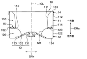
図2および図3に示すように、遠心ファン10は、複数の第1ブレード11、複数の第2ブレード12、主板13、側板14、および分離板15を有している。
As shown in FIGS. 2 and 3, the
複数の第1ブレード11は、ファン軸心CLの周りに並んで配置されている。複数の第1ブレード11それぞれは、気流に対して風上に位置する縁である第1前縁部111と、気流に対して風下に位置する縁である第1後縁部112とを有する。また、複数の第1ブレード11それぞれは、軸方向DRaの一方側の端である第1上端部113と、軸方向DRaの他方側の端部である第1下端部114とを有する。複数の第1ブレード11の相互間には、空気が流れる第1翼通路110が形成される。
The plurality of
複数の第1ブレード11は、第1翼通路110に対して空気が流入し易くなるように第1前縁部111とファン軸心CLとの距離が、軸方向DRaの一方側から他方側に向かって小さくなっている。なお、第1ブレード11の第1後縁部112は、軸方向DRaに沿って延びている。
In the plurality of
複数の第2ブレード12は、ファン軸心CLの周りに並んで配置されている。複数の第2ブレード12は、複数の第1ブレード11に対して軸方向DRaの他方側に位置付けられている。
The plurality of
複数の第2ブレード12それぞれは、気流に対して風上に位置する縁である第2前縁部121と、気流に対して風下に位置する縁である第2後縁部122とを有する。また、複数の第2ブレード12それぞれは、軸方向DRaの一方側の端である第2上端部123と、軸方向DRaの他方側の端部である第2下端部124とを有する。複数の第2ブレード12の相互間には、空気が流れる第2翼通路120が形成される。
Each of the plurality of
複数の第2ブレード12は、第2翼通路120に対して空気が流入し易くなるように第2前縁部121とファン軸心CLとの距離が、軸方向DRaの一方側から他方側に向かって小さくなっている。具体的には、第2前縁部121は、軸方向DRaに対して交差する方向に沿って直線状に延びている。なお、第2ブレード12の第2後縁部122は、軸方向DRaに沿って延びている。
In the plurality of
ここで、複数の第2ブレード12は、第2後縁部122の位置が、複数の第1ブレード11の第1後縁部112に対して、ファン軸心CLの周方向にずれた位置に設定されている。換言すれば、複数の第2ブレード12は、第2後縁部122が複数の第1ブレード11の第1後縁部112と軸方向DRaに重なり合わないように、第2後縁部122が第1後縁部112とは異なる位置に設定されている。
Here, in the plurality of
これにより、第1翼通路110と第2翼通路120とはファン軸心CLの周方向にずれることになる。なお、複数の第1ブレード11の第1前縁部111および複数の第2ブレード12の第2後縁部122については、ファン軸心CLの周方向において同じ位置でもよいし、異なる位置に設定されていてもよい。
As a result, the
また、本実施形態の遠心ファン10は、第2ブレード12の第2上端部123から第2下端部124までの軸方向長さL2が、第1ブレード11における第1上端部113から第1下端部114までの軸方向長さL1よりも短くなっている。なお、遠心ファン10は、第2ブレード12の軸方向長さL2が、第1ブレード11の軸方向長さL1と同等または大きくなっていてもよい。
Further, in the
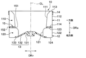
図3に示すように、主板13は、ファン軸心CLを中心とする円盤状の部材で構成されている。主板13は、その中心部に電動モータ20の回転軸22が相対回転不能に連結されるボス部131が設けられている。
As shown in FIG. 3, the
また、主板13は、ボス部131に連なるとともにファン軸心CLに交差するように傾斜する傾斜部132と、傾斜部132に連なるとともに径方向DRrに沿って延びる平坦部133とを有している。
Further, the
主板13は、径方向DRrの外側の部位に複数の第2ブレード12の第2下端部124に固定されている。具体的には、主板13は、傾斜部132の一部および平坦部133に複数の第2ブレード12の第2下端部124に固定されている。
The
側板14は、遠心ファン10を補強する部材である。側板14は、ファン軸心CLを中心とするリング状に形成されて、複数の第1ブレード11における軸方向DRaの一方側に位置する部位を支持している。具体的には、側板14は、径方向DRrの内側の内面が複数の第1ブレード11における軸方向DRaの一方側に位置する第1後縁部112に固定されている。
The
分離板15は、複数の第1ブレード11と複数の第2ブレード12とを接続する部材である。分離板15は、複数の第1ブレード11の相互間に形成される第1翼通路110を流れる空気と、複数の第2ブレード12の相互間に形成される第2翼通路120を流れる空気との混合を抑える部材でもある。
The
分離板15は、ファン軸心CLを中心とするリング状であって、その板面がファン軸心CLと直交するように拡がる板状部材で構成されている。分離板15は、径方向DRrの内側の端に位置する内側端面151、径方向DRrの外側の端に位置する外側端面152を有している。
The
分離板15には、軸方向DRaの一方側の板面に複数の第1ブレード11の第1下端部114が固定され、軸方向DRaの他方側の板面に複数の第2ブレード12の第2上端部123が固定されている。複数の第1ブレード11および複数の第2ブレード12は、それぞれが直に接することなく、分離板15を介して接続されている。すなわち、複数の第1ブレード11は、複数の第2ブレード12の第2上端部123に接することなく、第1下端部114が分離板15に接続されている。複数の第2ブレード12は、複数の第1ブレード11の第1下端部114に接することなく、第2上端部123が分離板15に接続されている。
The first
このように構成される遠心ファン10は、複数の第1ブレード11、複数の第2ブレード12、主板13、側板14、および分離板15が、射出成形等の成形技術によって、一体に成形された一体成形物として構成されている。遠心ファン10は、軸方向DRaの型抜きによって一体に成形可能なように、遠心ファン10を構成する各部品の形状、寸法等が適切に設定されている。このことについては、後述する。
In the
図1に戻り、電動モータ20は、遠心ファン10を回転させる電動式の駆動装置である。電動モータ20は、動力を発生させる本体部21、本体部21の動力によって回転する回転軸22、モータカバー23を有している。
Returning to FIG. 1, the
回転軸22は、本体部21から軸方向DRaの一方側に向かって延伸している。回転軸22は、モータキャップ24によって遠心ファン10の主板13に固定されている。これにより、回転軸22が回転すると、遠心ファン10が回転する。
The rotating
モータカバー23は、本体部21における軸方向DRaの他方側の部位を覆う部材である。モータカバー23は、本体部21を保持した状態で、ファンケーシング30に固定されている。
The
ファンケーシング30は、内部に遠心ファン10を収容する筐体である。ファンケーシング30には、遠心ファン10へ吸い込まれる空気が通過する吸入口31が形成されている。吸入口31は、遠心ファン10に対して軸方向DRaの一方側に位置する部位に形成されている。また、ファンケーシング30には、遠心ファン10に対して軸方向DRaの他方側に位置する部位に遠心ファン10を挿通させるためのファン挿通穴32が形成されている。
The
ファンケーシング30は、ベルマウス33、取付枠34、吹出通路形成部35、および仕切板36を有している。ベルマウス33は、ファンケーシング30において吸入口31の周縁部を構成する。ベルマウス33は、吸入口31に空気が円滑に流れるように、断面形状が円弧状に湾曲している。
The
取付枠34は、ファンケーシング30に対して内外気切替部40および分離筒50を取り付けるための矩形状の枠体である。取付枠34は、ファンケーシング30のうち遠心ファン10に対して軸方向DRaの一方側に位置する部位に設けられている。
The mounting
吹出通路形成部35は、遠心ファン10に対する径方向DRrの外側に、遠心ファン10から吹き出された空気が流れる吹出空気通路350を形成する部材である。吹出空気通路350は、遠心ファン10の周りに渦巻き状に形成されている。すなわち、ファンケーシング30は、遠心ファン10の周りに渦巻き状に吹出空気通路350が形成されている。このようなファンケーシング30は、スクロールケーシングとも呼ばれる。なお、ファンケーシング30は、スクロールケーシング以外のケーシングで構成されていてもよい。
The blowout
仕切板36は、吹出通路形成部35の内側に配置されている。仕切板36は、ファン軸心CLを中心とするリング状の板状部材で構成されている。仕切板36は、吹出空気通路350を軸方向DRaの一方側の第1吹出通路350Aと、第1吹出通路350Aに対して軸方向DRaの他方側に位置する第2吹出通路350Bとに仕切っている。
The
仕切板36は、径方向DRrの外側の部位が吹出通路形成部35の内壁に固定されている。仕切板36は、径方向DRrの内側の部位が、径方向DRrにおいて分離板15の径方向DRrの外側の部位と対向するように配置されている。これにより、遠心ファン10の第1翼通路110からの空気が第1吹出通路350Aに流入し、遠心ファン10の第2翼通路120からの空気が第2吹出通路350Bに流入する。
In the
図示しないが、吹出空気通路350の出口には、空調ユニットが接続されている。空調ユニットは、空気の通風路を形成する空調ケーシングの内部に、車室内へ吹き出す空気の温度を調整する冷却用熱交換器および加熱用熱交換器が収容されたユニットである。遠心ファン10の回転によりファンケーシング30から吹き出された空気は、空調ユニットの内部で所望の温度に調整された後、車室内に吹き出される。
Although not shown, an air conditioning unit is connected to the outlet of the blowout air passage 350. The air-conditioning unit is a unit in which a cooling heat exchanger and a heating heat exchanger that adjust the temperature of the air blown into the vehicle interior are housed inside the air-conditioning casing that forms the air passage. The air blown out from the
ファンケーシング30は、ある程度の弾性を有し、強度的にも優れた樹脂(例えば、ポリプロピレン)にて形成されている。ファンケーシング30は、樹脂成形上の都合、または、内蔵部品の組付上の都合等から、実際には、複数の分割体を組み付けた組付体で構成されている。なお、複数の分割体は、ネジやクリップ等の締結手段によって締結される。
The
内外気切替部40は、車両の内外から空気を切替導入するもので、ファンケーシング30における取付枠34に取り付けられている。内外気切替部40は、外殻を構成する内外気ケーシング41を有する。
The inside / outside
内外気ケーシング41は、ファンケーシング30に対して軸方向DRaの一方側に配置されている。内外気ケーシング41、吸入口31に導入する空気が通過する空気通路を形成する吸込ケーシングを構成する。内外気ケーシング41は、ある程度の弾性を有し、強度的にも優れた樹脂(例えば、ポリプロピレン)にて形成されている。
The inside /
内外気ケーシング41には、外気を導入する外気導入口411、内気を導入する第1内気導入口412および第2内気導入口413が形成されている。外気導入口411、第1内気導入口412、および第2内気導入口413は、ファン軸心CLに直交する所定の方向に並ぶように形成されている。
The inside /
ここで、内外気ケーシング41の内側には、外気導入口411からの外気または第1内気導入口412からの内気が導入される第1導入空間410Aと第2内気導入口413からの内気が導入される第2導入空間410Bとが形成されている。また、内外気ケーシング41には、第1導入空間410Aと第2導入空間410Bとを連通させる連通路414が形成されている。
Here, inside the inside /
内外気ケーシング41の内側には、エアフィルタ42が配置されている。エアフィルタ42は、内外気ケーシング41に導入された空気中の粉塵等を取り除く濾過材である。エアフィルタ42は、空気透過性を有する材料で構成されている。エアフィルタ42の材料としては、例えば、PET、PP等の樹脂繊維からなる不織布を採用することができる。
An
内外気ケーシング41には、エアフィルタ42の空気流れ上流側に各導入口411、412、413を開閉する開閉部材43が配置されている。開閉部材43は、外気導入口411および第1内気導入口412を選択的に開閉する第1開閉ドア431と、第2内気導入口413および連通路414を選択的に開閉する第2開閉ドア432と、を有している。
In the inside /
第1開閉ドア431は、第1ドア軸431aを中心に回動するロータリドアで構成されている。また、第2開閉ドア432は、第1開閉ドア431と同様に、第2ドア軸432aを中心に回動するロータリドアで構成されている。
The first opening / closing door 431 is composed of a rotary door that rotates about a
このように構成される内外気切替部40は、第1開閉ドア431で外気導入口411を開放し、且つ、第2開閉ドア432で第2内気導入口413を開放することで、内気を分離筒50の内側に流すとともに、分離筒50の内側に流すことが可能になっている。すなわち、内外気ケーシング41は、第2内気導入口413から導入された内気を分離筒50の内側に流すとともに、外気導入口411から導入された外気を分離筒50の外側に流すことが可能に構成されている。
The inside / outside
分離筒50は、軸方向DRaに延伸する筒状の部材である。すなわち、分離筒50は、軸方向DRaに沿って延びるとともに、軸方向DRaの両端に位置する部位が開口している。分離筒50は、遠心ファン10の径方向DRrの内側に配置される筒状の部位を含んでいる。分離筒50は、ある程度の弾性を有し、強度的にも優れた樹脂(例えば、ポリプロピレン)にて形成されている。
The
分離筒50は、吸入口31を通過する空気が筒状の部位の内側を流れる内側空気と筒状の部位の外側を流れる外側空気とに分離されるように、少なくとも一部がファンケーシング30の内側に位置付けられている。
The
分離筒50は、内外気ケーシング41の内側に位置する空気導入部位51、ファンケーシング30の内側に位置する空気導出部位52、空気導入部位51と空気導出部位52とを接続する中間部位53を有している。
The
空気導入部位51は、分離筒50のうち内外気ケーシング41に対して接続される部位である。空気導入部位51は、内外気ケーシング41の第2導入空間410Bに導入された空気が分離筒50の内側に流入するように、その上流側端部が第2導入空間410Bに向けて開口している。具体的には、空気導入部位51は、軸方向DRaの一方側から見た際の外形が略矩形状に形成されている。空気導入部位51は、ファンケーシング30のベルマウス33の略半分の領域を覆うことが可能な大きさを有している。
The
空気導出部位52および中間部位53は、分離筒50の内側を流れる内側空気および分離筒50の外側を流れる外側空気を遠心ファン10に導くための部位である。空気導出部位52は、内側空気と外側空気とを第1翼通路110および第2翼通路120へ導くために、軸方向DRaの他方側ほど径方向DRrへ拡がった形状になっている。すなわち、空気導出部位52は、軸方向DRaの他方側に向かって直径が拡大している。
The air lead-out
中間部位53は、空気導出部位52の中心軸がファン軸心CLと一致するように、少なくとも一部が軸方向DRaに対して傾斜した状態になっている。中間部位53は、その内側の断面積が空気導入部位51および空気導出部位52に比べて小さくなっている。
At least a part of the
分離筒50は、空気導出部位52における下流側の端部が、径方向DRrにおいて遠心ファン10の分離板15の内側端面151と対向するように配置されている。これにより、分離筒50の外側を流れる外側空気が遠心ファン10の第1翼通路110に流入し、分離筒50の内側を流れる内側空気が遠心ファン10の第2翼通路120に流入する。
The
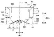
次に、遠心ファン10の形状、寸法等について、図4を参照して説明する。本実施形態では、説明の便宜上、各部品の寸法について以下のように定義する。複数の第1ブレード11については、第1前縁部111において最も小さい内径寸法を第1前縁径Dbi1とし、第1後縁部112において最も小さい外径寸法を第1後縁径Dbo1とする。複数の第2ブレード12については、第2前縁部121において最も大きい内径寸法を第2前縁径Dbi2とし、第2後縁部122において最も大きい外径寸法を第2後縁径Dbo2とする。側板14については、最も小さい内径寸法を側板内径Dspとする。主板13については、最も大きい外径寸法を主板外径Dbpとする。分離板15については、最も小さい内径寸法を分離板内径Dmp2とし、最も大きい外径寸法を分離板外径Dmp1とする。
Next, the shape, dimensions, and the like of the
図4に示すように、複数の第1ブレード11は、アンダーカットが生じないように、第1前縁部111および第1後縁部112それぞれのうち軸方向DRaの他方側の径寸法が軸方向DRaの一方側の径寸法以下に設定されている。具体的には、第1前縁部111は、第1下端部114側の内径寸法が第1上端部113側の内径寸法よりも小さくなっている。また、第1後縁部112は、第1下端部114側の外径寸法が第1上端部113側の外径寸法と同等になっている。
As shown in FIG. 4, in the plurality of
同様に、複数の第2ブレード12は、アンダーカットが生じないように、第2前縁部121および第2後縁部122それぞれのうち軸方向DRaの他方側の径寸法が軸方向DRaの一方側の径寸法以下に設定されている。具体的には、第2前縁部121は、第2下端部124側の内径寸法が第2上端部123側の内径寸法よりも小さくなっている。また、第2後縁部122は、第2下端部124側の外径寸法が第2上端部123側の外径寸法と同等になっている。
Similarly, in the plurality of
続いて、分離板15は、分離板内径Dmp2が主板外径Dbp以上であって、第2前縁径Dbi2以上、且つ、第1前縁径Dbi1以下に設定されている。すなわち、分離板15は、以下の式F1、F2の双方を満たすように分離板内径Dmp2が設定されている。
Subsequently, in the
Dmp2≧Dbp ・・・(F1)
Dbi2≦Dmp2≦Dbi1 ・・・(F2)
具体的には、遠心ファン10は、分離板内径Dmp2、主板外径Dbp、第2前縁径Dbi2、第1前縁径Dbi1が同程度の寸法に設定されている。なお、上述の式F1、F2を満足するのであれば、分離板内径Dmp2、主板外径Dbp、第2前縁径Dbi2、第1前縁径Dbi1が異なる寸法に設定されていてもよい。
Dmp2 ≧ Dbp ・ ・ ・ (F1)
Dbi2 ≤ Dmp2 ≤ Dbi1 ... (F2)
Specifically, the
さらに、分離板15は、分離板外径Dmp1が側板内径Dsp以下であって、第2後縁径Dbo2以上、且つ、第1後縁径Dbo1以下に設定されている。すなわち、分離板15は、以下の式F3、F4の双方を満たすように分離板外径Dmp1が設定されている。
Further, the
Dmp1≦Dsp ・・・(F3)
Dbo2≦Dmp1≦Dbo1 ・・・(F4)
具体的には、遠心ファン10は、分離板外径Dmp1、側板内径Dsp、第2後縁径Dbo2、第1後縁径Dbo1が同程度の寸法に設定されている。すなわち、遠心ファン10は、第2後縁径Dbo2が第1後縁径Dbo1と一致するように構成されている。なお、上述の式F3、F4を満足するのであれば、分離板外径Dmp1、側板内径Dsp、第2後縁径Dbo2、第1後縁径Dbo1が異なる寸法に設定されていてもよい。
Dmp1 ≤ Dsp ・ ・ ・ (F3)
Dbo2 ≤ Dmp1 ≤ Dbo1 ... (F4)
Specifically, the
また、図5に示すように、複数の第2ブレード12は、第2前縁部121の内径寸法が軸方向DRaの一方側から他方側に向かって小さくなっている。そして、複数の第2ブレード12は、第2前縁部121における軸方向DRaの他方側の端部における内径寸法が主板外径Dbpよりも小さくなっている。すなわち、複数の第2ブレード12は、第2下端部124側の部位が軸方向DRaにおいて主板13とラップするように、第2前縁部121がファン軸心CLに対して傾斜している。
Further, as shown in FIG. 5, in the plurality of
ここで、複数の第2ブレード12の第2前縁部121に対して垂直に近い角度で空気が流入させると、複数の第2ブレード12の第2前縁部121での空気の剥離を抑えることが可能となる。
Here, when air flows in at an angle close to perpendicular to the second
本実施形態の遠心ファン10は、複数の第2ブレード12に対して図5の矢印HLで示すように流入する。すなわち、複数の第2ブレード12には、空気が軸方向DRaから流入したり、図5の矢印HLで示すように、主板13の傾斜部132に沿った方向から流入したりすることがある。
The
これらを鑑み、複数の第2ブレード12は、子午面角度θinが、主板法線角度θnからファン軸心CLに対して垂直となる角度(すなわち、90°)までの範囲に設定されている。すなわち、複数の第2ブレード12は、以下の式F5を満たすように子午面角度θinが設定されている。
In view of these, the plurality of
θn≦θin≦90° ・・・(F5)
ここで、子午面角度θinは、ファン軸心CLに対する複数の第2ブレード12の子午面上の内周縁部の傾斜角度である。換言すれば、子午面角度θinは、第2前縁部121の接線TLとファン軸心CLとのなす角度である。また、主板法線角度θnは、ファン軸心CLに対する主板13の傾斜部132における法線ベクトルNLの傾斜角度である。換言すれば、主板法線角度θnは、法線ベクトルNLとファン軸心CLとのなす角度である。
θn ≦ θin ≦ 90 ° ・ ・ ・ (F5)
Here, the meridional angle θin is the inclination angle of the inner peripheral edge portion on the meridional surface of the plurality of
次に、遠心送風機1の作動を説明する。遠心送風機1は、空気の吸込モードとして、外気を吸い込む外気モード、内気を吸い込む内気モード、および外気と内気とを区分して同時に吸い込む内外気モードに設定可能になっている。
Next, the operation of the
外気モードは、内外気ケーシング41の内側に外気だけを導入するモードである。遠心送風機1は、外気モード時に、外気導入口411を開放する位置に第1開閉ドア431が変位し、連通路414を開放する位置に第2開閉ドア432が変位するように構成されている。
The outside air mode is a mode in which only the outside air is introduced inside the inside /
内気モードは、内外気ケーシング41の内側に内気だけを導入するモードである。遠心送風機1は、内気モード時に、第1内気導入口412を開放する位置に第1開閉ドア431が変位し、第2内気導入口413を開放する位置に第2開閉ドア432が変位するように構成されている。
The inside air mode is a mode in which only the inside air is introduced inside the inside /
内外気モードは、内外気ケーシング41の内側に外気および内気を導入するモードである。遠心送風機1は、内外気モード時に、外気導入口411を開放する位置に第1開閉ドア431が変位し、第2内気導入口413を開放する位置に第2開閉ドア432が変位するように構成されている。
The inside / outside air mode is a mode in which outside air and inside air are introduced inside the inside /
遠心送風機1は、内外気モード時に電動モータ20によって遠心ファン10が回転すると、図1に示すように、外気導入口411から第1導入空間410Aに外気が導入され、第2内気導入口413から第2導入空間410Bに内気が導入される。
In the
第1導入空間410Aに導入された外気は、分離筒50の外側を介して遠心ファン10の第1翼通路110に吸い込まれる。第1翼通路110に吸い込まれた外気は、第1吹出通路350Aに吹き出される。
The outside air introduced into the
一方、第2導入空間410Bに導入された内気は、分離筒50の内側を介して遠心ファン10の第2翼通路120に吸い込まれる。第2翼通路120に吸い込まれた外気は、第2吹出通路350Bに吹き出される。
On the other hand, the inside air introduced into the
図示しないが、第1吹出通路350Aを流れる外気および第2吹出通路350Bを流れる内気は、ファンケーシング30から空調ユニットに導入され、空調ユニットの内部で所望の温度に調整された後、異なる吹出口から車室内へ吹出される。
Although not shown, the outside air flowing through the first outlet passage 350A and the inside air flowing through the second outlet passage 350B are introduced into the air conditioning unit from the
以上説明した遠心送風機1の遠心ファン10は、複数の第1ブレード11および複数の第2ブレード12それぞれが直に接することなく分離板15を介して接続されている。このため、第1ブレード11および第2ブレード12それぞれを独立したブレードとして設計することができる。
The
加えて、遠心ファン10は、軸方向DRaの型抜きによって一体に成形可能なように、遠心ファン10を構成する各部品の形状、寸法等が適切に設定されている。すなわち、遠心ファン10は、分離板15の分離板内径Dmp2が上述の式F1、F2の双方を満たし、分離板15の分離板外径Dmp1が上述の式F3、F4の双方を満たすように設定されている。これらによると、遠心ファン10を軸方向DRaの型抜きによって成形する際にアンダーカットとなる部位がないので、軸方向DRaの型抜きによる一体成形よって遠心ファン10を製造することが可能になる。
In addition, the shape, dimensions, and the like of each component constituting the
したがって、本実施形態によれば、第1ブレード11および第2ブレード12の設計自由度を確保しつつ、製造性に優れた遠心ファン10および遠心送風機1を実現することができる。
Therefore, according to the present embodiment, it is possible to realize the
また、遠心ファン10の第2ブレード12は、第2前縁部121の内径寸法が軸方向DRaの一方側から他方側に向かって小さくなっており、第2前縁部121における軸方向DRaの他方側の端部における内径寸法が主板外径Dbpよりも小さくなっている。
Further, in the
これによると、遠心ファン10は、軸方向DRaの他方側において、第2ブレード12と主板13との接続部分の長さを大きくすることができるので、第2ブレード12と主板13との接続強度を充分に確保することが可能になる。
According to this, the
加えて、複数の第2ブレード12は、子午面角度θinが、主板法線角度θnからファン軸心CLに対して垂直となる角度までの範囲に設定されている。これによると、吸入口31から吸入された空気が第2ブレード12の第2前縁部121に対して垂直に近い角度で流入し易くなる。これにより、第2前縁部121での空気の剥離が抑制されることで、第2翼通路120での空気の乱れが発生し難くなり、騒音の低減を図ることができる。
In addition, the plurality of
また、複数の第2ブレード12は、第2後縁径Dbo2が第1後縁径Dbo1と一致するように構成されている。このように、第2後縁径Dbo2を第1後縁径Dbo1と一致する大きさとすれば、遠心ファン10における複数の第2ブレード12で構成される部位の外径が大きくなる。このため、遠心ファン10における複数の第2ブレード12で構成される部位のファン性能が向上する。ここで、「一致」とは、比較する寸法が完全に同じ状態だけを示すものではなく、比較する寸法が製造誤差レベルの微小なズレ(例えば、平均寸法に対して5%以内)しかない状態も含まれる。
Further, the plurality of
さらに、複数の第2ブレード12は、第2後縁部122が、複数の第1ブレード11の第1後縁部112の位置に対してファン軸心CLの周方向にずれた位置に設定されている。このように、第2ブレード12の第2後縁部122を第1ブレード11の第1後縁部112に対してファン軸心CLの周方向にずれた位置に設定すれば、第1翼通路110と第2翼通路120とがファン軸心CLの周方向にずれることになる。これによると、第1翼通路110の出口側で生ずる騒音および第2翼通路120の出口側で生ずる騒音それぞれの位相がずれることで、遠心ファン10の空気吹出側における騒音(いわゆる、Nz音)の発生を抑制することができる。
Further, the plurality of
(他の実施形態)
以上、本開示の代表的な実施形態について説明したが、本開示は、上述の実施形態に限定されることなく、例えば、以下のように種々変形可能である。
(Other embodiments)
Although the typical embodiments of the present disclosure have been described above, the present disclosure is not limited to the above-described embodiments, and can be variously modified as follows, for example.
(第1変形例)
上述の実施形態では、遠心ファン10として、第2ブレード12の第2前縁部121が軸方向DRaに対して交差する方向に沿って直線状に延びているものを例示したが、これに限定されない。遠心ファン10は、例えば、図6に示すように、第2ブレード12の第2前縁部121が円弧状の曲線を描くような形状になっていてもよい。
(First modification)
In the above-described embodiment, the
(第2変形例)
また、遠心ファン10は、例えば、図7に示すように、第2ブレード12の第2前縁部121が円弧状の曲線と軸方向DRaに沿って延びる直線とを組み合わせた形状になっていてもよい。
(Second modification)
Further, as shown in FIG. 7, for example, the
(第3変形例)
上述の実施形態では、遠心ファン10として、第1ブレード11の第1前縁部111に抜き勾配が設定されているものを例示したが、これに限定されない。遠心ファン10は、例えば、図8に示すように、第1ブレード11の第1前縁部111に抜き勾配が設定されていなくてもよい。すなわち、第1ブレード11には、第1前縁部111の少なくとも一部が軸方向DRaに沿って延びていてもよい。
(Third modification example)
In the above-described embodiment, the
(第4変形例)
上述の実施形態では、遠心ファン10として、第1ブレード11の第1後縁部112が軸方向DRaに沿って延びているものを例示したが、これに限定されない。遠心ファン10は、例えば、図9に示すように、第1ブレード11の第1後縁部112に抜き勾配が設定されていてもよい。すなわち、第1ブレード11は、第1後縁部112とファン軸心CLとの距離が軸方向DRaの一方側から他方側に向かって小さくなっていてもよい。
(Fourth modification)
In the above-described embodiment, as the
(第5変形例)
また、遠心ファン10は、例えば、図10に示すように、第1ブレード11の第1後縁部112および第2ブレード12の第2後縁部122の双方に抜き勾配が設定されていてもよい。すなわち、遠心ファン10は、第1ブレード11の第1後縁部112とファン軸心CLとの距離および第2ブレード12の第2後縁部122とファン軸心CLとの距離が、軸方向DRaの一方側から他方側に向かって小さくなっていてもよい。
(Fifth modification)
Further, in the
(第6変形例)
上述の実施形態では、遠心ファン10として、第2ブレード12の第2後縁径Dbo2が第1ブレード11の第1後縁径Dbo1および分離板外径Dmp1と一致するように構成されているものを例示したが、これに限定されない。遠心ファン10は、例えば、図11に示すように、第2ブレード12の第2後縁径Dbo2が第1ブレード11の第1後縁径Dbo1および分離板外径Dmp1よりも小さくなっていてもよい。
(6th modification)
In the above-described embodiment, the
(第7変形例)
上述の実施形態では、遠心ファン10として、第1ブレード11の第1前縁径Dbi1が第2ブレード12の第2前縁径Dbi2および分離板内径Dmp2と一致するように構成されているものを例示したが、これに限定されない。遠心ファン10は、例えば、図12に示すように、第1ブレード11の第1前縁径Dbi1が第2ブレード12の第2前縁径Dbi2および分離板内径Dmp2よりも大きくなっていてもよい。
(7th modification)
In the above-described embodiment, the
(第8変形例)
上述の実施形態では、遠心ファン10の主板13として、傾斜部132および平坦部133を有するものを例示したが、これに限定されない。遠心ファン10は、例えば、図13に示すように、平坦部133が省略された主板13が採用されていてもよい。なお、図13に示す遠心ファン10では、分離板内径Dmp2が主板外径Dbpよりも大きくなる。
(8th modification)
In the above-described embodiment, the
(第9変形例)
上述の実施形態では、遠心ファン10の分離板15として、板面がファン軸心CLと直交するように拡がるものを例示したが、これに限定されない。遠心ファン10は、例えば、図14に示すように、分離板15の板面が主板13の傾斜部132と同様の向きに傾斜する形状になっていてもよい。
(9th modification)
In the above-described embodiment, the separating
(他の変形例)
上述の実施形態では、遠心ファン10として、第2ブレード12の第2前縁部121の内径寸法が、軸方向DRaの一方側から他方側に向かって小さくなっているものを例示したが、これに限定されない。遠心ファン10は、第2ブレード12の第2前縁部121が軸方向DRaに沿って直線状に延びる形状になっていてもよい。
(Other variants)
In the above-described embodiment, the
上述の実施形態では、遠心ファン10として、第2ブレード12の第2後縁部122の位置が、第1ブレード11の第1後縁部112に対して、ファン軸心CLの周方向にずれた位置に設定されているものを例示したが、これに限定されない。遠心ファン10は、例えば、第2ブレード12の第2後縁部122の位置が、第1ブレード11の第1後縁部112と同様の位置に設定されていてもよい。
In the above-described embodiment, as the
上述の実施形態では、1つの外気導入口と2つの内気導入口が形成された内外気ケーシング41を例示したが、これに限定されない。内外気ケーシング41は、外気と内気とを区分して吸入することが可能であれば、例えば、1つの外気導入口と1つの内気導入口とが形成されたものが採用されていてもよい。
In the above-described embodiment, the inside /
上述の実施形態では、開閉部材43が第1開閉ドア431および第2開閉ドア432で構成されるものを例示したが、これに限定されない。開閉部材43は、例えば、3つ以上の開閉ドアで構成されていてもよい。また、開閉部材43を構成する開閉ドアは、ロータリドアに限らず、例えば、片持式の板ドア、スライドドア等で構成されていてもよい。 In the above-described embodiment, the opening / closing member 43 is exemplified by the first opening / closing door 431 and the second opening / closing door 432, but the present invention is not limited thereto. The opening / closing member 43 may be composed of, for example, three or more opening / closing doors. Further, the opening / closing door constituting the opening / closing member 43 is not limited to the rotary door, and may be composed of, for example, a cantilever type plate door, a sliding door, or the like.
上述の実施形態では、本開示の遠心送風機1を内外気二層式の車両用空調装置に適用した例について説明したが、これに限定されない。本開示の遠心送風機1は、内外気二層式の車両用空調装置以外の装置にも適用可能である。
In the above-described embodiment, an example in which the
上述の実施形態において、実施形態を構成する要素は、特に必須であると明示した場合および原理的に明らかに必須であると考えられる場合等を除き、必ずしも必須のものではないことは言うまでもない。 Needless to say, in the above-described embodiment, the elements constituting the embodiment are not necessarily essential except when it is clearly indicated that they are essential and when they are clearly considered to be essential in principle.
上述の実施形態において、実施形態の構成要素の個数、数値、量、範囲等の数値が言及されている場合、特に必須であると明示した場合および原理的に明らかに特定の数に限定される場合等を除き、その特定の数に限定されない。 In the above-described embodiment, when numerical values such as the number, numerical value, quantity, range, etc. of the components of the embodiment are mentioned, when it is clearly indicated that it is particularly essential, and when it is clearly limited to a specific number in principle. Except for cases, etc., it is not limited to the specific number.
上述の実施形態において、構成要素等の形状、位置関係等に言及するときは、特に明示した場合および原理的に特定の形状、位置関係等に限定される場合等を除き、その形状、位置関係等に限定されない。 In the above-described embodiment, when the shape, positional relationship, etc. of a component or the like is referred to, the shape, positional relationship, etc. are not specified unless otherwise specified or limited in principle to a specific shape, positional relationship, etc. Not limited to, etc.
(まとめ)
上述の実施形態の一部または全部で示された第1の観点によれば、遠心ファンは、複数の第1ブレードおよび複数の第2ブレードそれぞれが直に接することなく分離板を介して接続されている。複数の第1ブレードの前縁部および後縁部は、軸方向の他方側における径寸法が軸方向の一方側における径寸法以下になっている。複数の第2ブレードの前縁部および後縁部は、軸方向の他方側の径寸法が軸方向の一方側の径寸法以下になっている。分離板は、分離板内径が主板外径以上であって第2前縁径以上、且つ、第1前縁径以下であり、分離板外径が側板内径以下であって第2後縁径以上、且つ、第1後縁径以下になっている。
(summary)
According to the first aspect shown in part or all of the above embodiments, the centrifugal fan is connected via a separating plate without direct contact with each of the plurality of first blades and the plurality of second blades. ing. The leading edge portion and the trailing edge portion of the plurality of first blades have a diametrical dimension on the other side in the axial direction that is equal to or smaller than the diametrical dimension on the one side in the axial direction. The leading edge portion and the trailing edge portion of the plurality of second blades have a diameter dimension on the other side in the axial direction that is equal to or less than the diameter dimension on the one side in the axial direction. In the separation plate, the inner diameter of the separation plate is equal to or greater than the outer diameter of the main plate and is equal to or greater than the diameter of the second leading edge, and is equal to or less than the diameter of the first leading edge. Moreover, it is equal to or smaller than the first trailing edge diameter.
第2の観点によれば、遠心ファンは、複数の第2ブレードの前縁部の内径寸法が軸方向の一方側から他方側に向かって小さくなっており、複数の第2ブレードの前縁部における軸方向の他方側の端部における内径寸法が主板外径よりも小さくなっている。 According to the second aspect, in the centrifugal fan, the inner diameter dimension of the leading edge portion of the plurality of second blades is reduced from one side to the other side in the axial direction, and the leading edge portion of the plurality of second blades is reduced. The inner diameter dimension at the other end in the axial direction is smaller than the outer diameter of the main plate.
これによると、遠心ファンは、軸方向の他方側において、第2ブレードと主板との接続部分の長さを大きくすることができるので、第2ブレードと主板との接続強度を充分に確保することが可能になる。 According to this, the centrifugal fan can increase the length of the connection portion between the second blade and the main plate on the other side in the axial direction, so that the connection strength between the second blade and the main plate is sufficiently secured. Will be possible.
第3の観点によれば、遠心ファンは、複数の第2ブレードの子午面角度が、主板法線角度からファン軸心に対して垂直となる角度までの範囲に設定されている。
但し、子午面角度は、ファン軸心に対する複数の第2ブレードの子午面上の内周縁部の傾斜角度である。また、主板法線角度は、ファン軸心に対する主板の法線ベクトルの傾斜角度である。
According to the third aspect, the centrifugal fan is set so that the meridional angles of the plurality of second blades are set in a range from the main plate normal angle to the angle perpendicular to the fan axis.
However, the meridional angle is the inclination angle of the inner peripheral edge portion on the meridional surface of the plurality of second blades with respect to the fan axis. The main plate normal angle is the inclination angle of the main plate normal vector with respect to the fan axis.
これによると、吸入口から吸入された空気が第2ブレードの前縁部に対して垂直に近い角度で流入し易くなる。これにより、第2ブレード間での空気の乱れが発生し難くなり、騒音の低減を図ることができる。ここで、「子午面」とは、遠心ファンにおけるファン軸心を含む断面にブレードの形状を回転投影させた面である。 According to this, the air sucked from the suction port tends to flow in at an angle close to perpendicular to the leading edge portion of the second blade. As a result, air turbulence between the second blades is less likely to occur, and noise can be reduced. Here, the "meriplane" is a plane obtained by rotationally projecting the shape of the blade onto the cross section of the centrifugal fan including the fan axis.
第4の観点によれば、遠心ファンは、複数の第2ブレードの第2後縁径が第1後縁径と一致するように構成されている。このように、第2後縁径を第1後縁径と一致する大きさとすれば、遠心ファンにおける複数の第2ブレードで構成される部位の外径が大きくなるので、遠心ファンにおける複数の第2ブレードで構成される部位のファン性能が向上する。ここで、「一致」とは、比較する寸法が完全に同じ状態だけを示すものではなく、比較する寸法が製造誤差レベルの微小なズレ(例えば、平均寸法に対して5%以内)しかない状態も含まれる。 According to the fourth aspect, the centrifugal fan is configured such that the second trailing edge diameter of the plurality of second blades coincides with the first trailing edge diameter. In this way, if the second trailing edge diameter is set to a size that matches the first trailing edge diameter, the outer diameter of the portion composed of the plurality of second blades in the centrifugal fan becomes large, so that the plurality of second trailing edges in the centrifugal fan become large. The fan performance of the part composed of 2 blades is improved. Here, "matching" does not mean that the dimensions to be compared are exactly the same, but the dimensions to be compared are only a slight deviation of the manufacturing error level (for example, within 5% of the average dimension). Is also included.
第5の観点によれば、遠心ファンは、複数の第2ブレードの後縁部が、複数の第1ブレードの後縁部の位置に対してファン軸心の周方向にずれた位置に設定されている。このように、第2ブレードの後縁部を第1ブレードの後縁部に対してファン軸心の周方向にずれた位置に設定すれば、第1翼通路と第2翼通路とがファン軸心の周方向にずれることになる。これによると、第1翼通路の出口側で生ずる騒音および第2翼通路の出口側で生ずる騒音それぞれの位相がずれることで、遠心ファンの空気吹出側における騒音(いわゆる、Nz音)の発生を抑制することができる。 According to the fifth aspect, the centrifugal fan is set so that the trailing edges of the plurality of second blades are displaced in the circumferential direction of the fan axis with respect to the positions of the trailing edges of the plurality of first blades. ing. In this way, if the trailing edge of the second blade is set at a position shifted in the circumferential direction of the fan axis with respect to the trailing edge of the first blade, the first wing passage and the second wing passage are set to the fan shaft. It will shift in the circumferential direction of the heart. According to this, the noise generated on the outlet side of the first wing passage and the noise generated on the outlet side of the second wing passage are out of phase with each other, so that the noise generated on the air blowing side of the centrifugal fan (so-called Nz sound) is generated. It can be suppressed.
第6の観点によれば、遠心送風機の遠心ファンは、複数の第1ブレードおよび複数の第2ブレードそれぞれが直に接することなく分離板を介して接続されている。複数の第1ブレードの前縁部および後縁部は、軸方向の他方側における径寸法が軸方向の一方側における径寸法以下になっている。複数の第2ブレードの前縁部および後縁部は、軸方向の他方側の径寸法が軸方向の一方側の径寸法以下になっている。分離板は、分離板内径が主板外径以上であって第2前縁径以上、且つ、第1前縁径以下であり、分離板外径が側板内径以下であって第2後縁径以上、且つ、第1後縁径以下になっている。 According to the sixth aspect, the centrifugal fan of the centrifugal blower is connected via the separating plate without direct contact with each of the plurality of first blades and the plurality of second blades. The leading edge portion and the trailing edge portion of the plurality of first blades have a diametrical dimension on the other side in the axial direction that is equal to or smaller than the diametrical dimension on the one side in the axial direction. The leading edge portion and the trailing edge portion of the plurality of second blades have a diameter dimension on the other side in the axial direction that is equal to or less than the diameter dimension on the one side in the axial direction. In the separation plate, the inner diameter of the separation plate is equal to or greater than the outer diameter of the main plate and is equal to or greater than the diameter of the second leading edge, and is equal to or less than the diameter of the first leading edge. Moreover, it is equal to or smaller than the first trailing edge diameter.
10 遠心ファン
11 第1ブレード
111 第1前縁部(第1ブレードの前縁部)
112 第1後縁部(第1ブレードの後縁部)
12 第2ブレード
121 第2前縁部(第2ブレードの前縁部)
122 第2後縁部(第2ブレードの後縁部)
13 主板
14 側板
15 分離板
10
112 1st trailing edge (trailing edge of 1st blade)
12
122 2nd trailing edge (trailing edge of 2nd blade)
13
Claims (5)
前記ファン軸心の周りに配置された複数の第1ブレード(11)と、
前記ファン軸心の周りに配置されて前記複数の第1ブレードに対して前記軸方向の他方側に位置する複数の第2ブレード(12)と、
前記ファン軸心を中心とするリング状に形成されて前記複数の第1ブレードの前記軸方向の一方側に位置する部位を支持する側板(14)と、
前記複数の第2ブレードの前記軸方向の他方側に位置する部位を支持する主板(13)と、
前記複数の第1ブレードと前記複数の第2ブレードとを接続するとともに前記複数の第1ブレードの相互間に形成される第1翼通路(110)を流れる空気と前記複数の第2ブレードの相互間に形成される第2翼通路(120)を流れる空気との混合を抑える分離板(15)と、を備え、
前記複数の第1ブレードおよび前記複数の第2ブレードは、それぞれが直に接することなく前記分離板を介して接続されており、
前記複数の第1ブレードの前縁部(111)において最も小さい内径寸法を第1前縁径(Dbi1)、前記複数の第1ブレードの後縁部(112)において最も小さい外径寸法を第1後縁径(Dbo1)、前記複数の第2ブレードの前縁部(121)において最も大きい内径寸法を第2前縁径(Dbi2)、前記複数の第2ブレードの後縁部(122)において最も大きい外径寸法を第2後縁径(Dbo2)、前記側板において最も小さい内径寸法を側板内径(Dsp)、前記主板において最も大きい外径寸法を主板外径(Dbp)、前記分離板において最も小さい内径寸法を分離板内径(Dmp2)、前記分離板において最も大きい外径寸法を分離板外径(Dmp1)としたとき、
前記複数の第1ブレードの前縁部および後縁部は、前記軸方向の他方側における径寸法が前記軸方向の一方側における径寸法以下になっており、
前記複数の第2ブレードの前縁部および後縁部は、前記軸方向の他方側の径寸法が前記軸方向の一方側の径寸法以下になっており、
前記分離板は、前記分離板内径が前記主板外径以上であって前記第2前縁径以上、且つ、前記第1前縁径以下であり、前記分離板外径が前記側板内径以下であって前記第2後縁径以上、且つ、前記第1後縁径以下であり、
前記複数の第2ブレードは、前縁部の内径寸法が前記軸方向の一方側から他方側に向かって小さくなっており、前記複数の第2ブレードの前縁部における前記軸方向の他方側の端部における内径寸法が前記主板外径よりも小さくなっており、前記複数の第2ブレードの前縁部と前記ファン軸心との距離が前記軸方向の一方側から他方側に向かって小さくなるように前記複数の第2ブレードの前縁部の全体が軸方向に対して交差する方向に沿って直線状に延びている、遠心ファン。 A centrifugal fan that blows out air sucked from one side in the axial direction (DRa) of the fan axis (CL) to the outside in the radial direction (DRr).
A plurality of first blades (11) arranged around the fan axis, and
A plurality of second blades (12) arranged around the fan axis and located on the other side in the axial direction with respect to the plurality of first blades.
A side plate (14) formed in a ring shape centered on the fan axis and supporting a portion of the plurality of first blades located on one side in the axial direction.
A main plate (13) that supports a portion of the plurality of second blades located on the other side in the axial direction, and a main plate (13).
The air flowing through the first blade passage (110) formed between the plurality of first blades and the plurality of second blades are connected to each other and the plurality of second blades are connected to each other. A separation plate (15) that suppresses mixing with air flowing through the second wing passage (120) formed between them is provided.
The plurality of first blades and the plurality of second blades are connected to each other via the separation plate without being in direct contact with each other.
The smallest inner diameter dimension in the front edge portion (111) of the plurality of first blades is the first front edge diameter (Dbi1), and the smallest outer diameter dimension in the trailing edge portion (112) of the plurality of first blades is the first. The trailing edge diameter (Dbo1), the largest inner diameter dimension in the front edge portion (121) of the plurality of second blades, is the largest in the second front edge diameter (Dbi2), the trailing edge portion (122) of the plurality of second blades. The large outer diameter dimension is the second trailing edge diameter (Dbo2), the smallest inner diameter dimension in the side plate is the side plate inner diameter (Dsp), the largest outer diameter dimension in the main plate is the main plate outer diameter (Dbp), and the smallest in the separation plate. When the inner diameter is the inner diameter of the separation plate (Dmp2) and the largest outer diameter of the separation plate is the outer diameter of the separation plate (Dmp1).
The leading edge portion and the trailing edge portion of the plurality of first blades have a diameter dimension on the other side in the axial direction that is equal to or less than the diameter dimension on the one side in the axial direction.
The leading edge portion and the trailing edge portion of the plurality of second blades have a diameter dimension on the other side in the axial direction equal to or smaller than the diameter dimension on the one side in the axial direction.
The separation plate has an inner diameter of the separation plate equal to or greater than the outer diameter of the main plate, equal to or greater than the diameter of the second leading edge and equal to or less than the diameter of the first leading edge, and the outer diameter of the separation plate is equal to or less than the inner diameter of the side plate. The diameter is equal to or greater than the second trailing edge diameter and equal to or less than the first trailing edge diameter.
The inner diameter of the leading edge portion of the plurality of second blades decreases from one side in the axial direction toward the other side, and the other side in the axial direction of the leading edge portion of the plurality of second blades. The inner diameter at the end is smaller than the outer diameter of the main plate, and the distance between the leading edge of the plurality of second blades and the center of the fan axis decreases from one side in the axial direction to the other side. As described above, a centrifugal fan in which the entire leading edge portion of the plurality of second blades extends linearly along a direction intersecting the axial direction.
前記複数の第2ブレードは、前記子午面角度が、前記主板法線角度から前記ファン軸心に対して垂直となる角度までの範囲に設定されている請求項1に記載の遠心ファン。 When the inclination angle of the inner peripheral edge portion of the plurality of second blades on the meridional plane with respect to the fan axis is the meridional angle, and the inclination angle of the normal vector of the main plate with respect to the fan axis is the main plate normal angle. ,
The centrifugal fan according to claim 1, wherein the plurality of second blades are set in a range in which the meridional angle is set in a range from the main plate normal angle to an angle perpendicular to the fan axis.
ファン軸心(CL)の軸方向(DRa)の一方側から吸い込んだ空気を径方向(DRr)外側に吹き出す遠心ファン(10)と、
前記遠心ファンを収容し、前記遠心ファンに対し前記軸方向の一方側に前記遠心ファンへ吸い込まれる空気が通過する吸入口(31)が形成されたファンケーシング(30)と、
前記遠心ファンの径方向の内側に配置される筒状の部位を含み、前記吸入口を通過する空気を前記筒状の部位の内側を流れる内側空気と前記筒状の部位の外側を流れる外側空気とに分離する分離筒(50)と、を備え、
前記遠心ファンは、
前記ファン軸心の周りに配置された複数の第1ブレード(11)と、
前記ファン軸心の周りに配置されて前記複数の第1ブレードに対して前記軸方向の他方側に位置する複数の第2ブレード(12)と、
前記ファン軸心を中心とするリング状に形成されて前記複数の第1ブレードの前記軸方向の一方側を支持する側板(14)と、
前記複数の第2ブレードの前記軸方向の他方側を支持する主板(13)と、
前記複数の第1ブレードと前記複数の第2ブレードとを接続するとともに前記複数の第1ブレードの相互間に形成される第1翼通路(110)を流れる空気と前記複数の第2ブレードの相互間に形成される第2翼通路(120)を流れる空気との混合を抑える分離板(15)と、を含んで構成され、
前記複数の第1ブレードおよび前記複数の第2ブレードは、それぞれが直に接することなく前記分離板を介して接続されており、
前記複数の第1ブレードの前縁部(111)において最も小さい内径寸法を第1前縁径(Dbi1)、前記複数の第1ブレードの後縁部(112)において最も小さい外径寸法を第1後縁径(Dbo1)、前記複数の第2ブレードの前縁部(121)において最も大きい内径寸法を第2前縁径(Dbi2)、前記複数の第2ブレードの後縁部(122)において最も大きい外径寸法を第2後縁径(Dbo2)、前記側板において最も小さい内径寸法を側板内径(Dsp)、前記主板において最も大きい外径寸法を主板外径(Dbp)、前記分離板において最も小さい内径寸法を分離板内径(Dmp2)、前記分離板において最も大きい外径寸法を分離板外径(Dmp1)としたとき、
前記複数の第1ブレードの前縁部および後縁部は、前記軸方向の他方側における径寸法が前記軸方向の一方側における径寸法以下になっており、
前記複数の第2ブレードの前縁部および後縁部は、前記軸方向の他方側の径寸法が前記軸方向の一方側の径寸法以下になっており、
前記分離板は、
前記分離板内径が前記主板外径以上であって前記第2前縁径以上、且つ、前記第1前縁径以下であり、
前記分離板外径が前記側板内径以下であって前記第2後縁径以上、且つ、前記第1後縁径以下であり、
前記複数の第2ブレードは、前縁部の内径寸法が前記軸方向の一方側から他方側に向かって小さくなっており、前記複数の第2ブレードの前縁部における前記軸方向の他方側の端部における内径寸法が前記主板外径よりも小さくなっており、前記複数の第2ブレードの前縁部と前記ファン軸心との距離が前記軸方向の一方側から他方側に向かって小さくなるように前記複数の第2ブレードの前縁部の全体が軸方向に対して交差する方向に沿って直線状に延びている、遠心送風機。 It ’s a centrifugal blower,
A centrifugal fan (10) that blows out air sucked from one side of the fan axis (CL) in the axial direction (DRa) to the outside in the radial direction (DRr).
A fan casing (30) accommodating the centrifugal fan and having a suction port (31) formed on one side of the centrifugal fan in the axial direction through which air sucked into the centrifugal fan passes.
The inside air flowing inside the tubular part and the outside air flowing outside the tubular part include the cylindrical part arranged inside the centrifugal fan in the radial direction and passing through the suction port. With a separation cylinder (50) that separates into and
The centrifugal fan
A plurality of first blades (11) arranged around the fan axis, and
A plurality of second blades (12) arranged around the fan axis and located on the other side in the axial direction with respect to the plurality of first blades.
A side plate (14) formed in a ring shape centered on the fan axis and supporting one side of the plurality of first blades in the axial direction, and a side plate (14).
A main plate (13) that supports the other side of the plurality of second blades in the axial direction, and
The air flowing through the first blade passage (110) formed between the plurality of first blades and the plurality of second blades are connected to each other and the plurality of second blades are connected to each other. It is configured to include a separation plate (15) that suppresses mixing with air flowing through the second wing passage (120) formed between them.
The plurality of first blades and the plurality of second blades are connected to each other via the separation plate without being in direct contact with each other.
The smallest inner diameter dimension in the front edge portion (111) of the plurality of first blades is the first front edge diameter (Dbi1), and the smallest outer diameter dimension in the trailing edge portion (112) of the plurality of first blades is the first. The trailing edge diameter (Dbo1), the largest inner diameter dimension in the front edge portion (121) of the plurality of second blades, is the largest in the second front edge diameter (Dbi2), the trailing edge portion (122) of the plurality of second blades. The large outer diameter dimension is the second trailing edge diameter (Dbo2), the smallest inner diameter dimension in the side plate is the side plate inner diameter (Dsp), the largest outer diameter dimension in the main plate is the main plate outer diameter (Dbp), and the smallest in the separation plate. When the inner diameter is the inner diameter of the separation plate (Dmp2) and the largest outer diameter of the separation plate is the outer diameter of the separation plate (Dmp1).
The leading edge portion and the trailing edge portion of the plurality of first blades have a diameter dimension on the other side in the axial direction that is equal to or less than the diameter dimension on the one side in the axial direction.
The leading edge portion and the trailing edge portion of the plurality of second blades have a diameter dimension on the other side in the axial direction equal to or smaller than the diameter dimension on the one side in the axial direction.
The separation plate is
The inner diameter of the separation plate is equal to or larger than the outer diameter of the main plate, equal to or greater than the diameter of the second leading edge, and equal to or smaller than the diameter of the first leading edge.
The outer diameter of the separation plate is equal to or less than the inner diameter of the side plate, equal to or greater than the second trailing edge diameter, and equal to or less than the first trailing edge diameter.
The inner diameter of the leading edge portion of the plurality of second blades decreases from one side in the axial direction toward the other side, and the other side in the axial direction of the leading edge portion of the plurality of second blades. The inner diameter at the end is smaller than the outer diameter of the main plate, and the distance between the leading edge of the plurality of second blades and the center of the fan axis decreases from one side in the axial direction to the other side. As described above, a centrifugal blower in which the entire leading edge portion of the plurality of second blades extends linearly along a direction intersecting the axial direction.
Priority Applications (4)
| Application Number | Priority Date | Filing Date | Title |
|---|---|---|---|
| JP2018234595A JP7003902B2 (en) | 2018-12-14 | 2018-12-14 | Centrifugal fan, centrifugal fan |
| PCT/JP2019/044713 WO2020121729A1 (en) | 2018-12-14 | 2019-11-14 | Centrifugal fan and centrifugal blower |
| CN201980082424.8A CN113167295B (en) | 2018-12-14 | 2019-11-14 | Centrifugal fan and centrifugal blower |
| US17/323,065 US11499568B2 (en) | 2018-12-14 | 2021-05-18 | Centrifugal fan and centrifugal blower |
Applications Claiming Priority (1)
| Application Number | Priority Date | Filing Date | Title |
|---|---|---|---|
| JP2018234595A JP7003902B2 (en) | 2018-12-14 | 2018-12-14 | Centrifugal fan, centrifugal fan |
Publications (3)
| Publication Number | Publication Date |
|---|---|
| JP2020094571A JP2020094571A (en) | 2020-06-18 |
| JP2020094571A5 JP2020094571A5 (en) | 2021-02-25 |
| JP7003902B2 true JP7003902B2 (en) | 2022-02-04 |
Family
ID=71076982
Family Applications (1)
| Application Number | Title | Priority Date | Filing Date |
|---|---|---|---|
| JP2018234595A Active JP7003902B2 (en) | 2018-12-14 | 2018-12-14 | Centrifugal fan, centrifugal fan |
Country Status (4)
| Country | Link |
|---|---|
| US (1) | US11499568B2 (en) |
| JP (1) | JP7003902B2 (en) |
| CN (1) | CN113167295B (en) |
| WO (1) | WO2020121729A1 (en) |
Families Citing this family (1)
| Publication number | Priority date | Publication date | Assignee | Title |
|---|---|---|---|---|
| FR3086208B1 (en) * | 2018-09-25 | 2020-12-18 | Valeo Systemes Thermiques | AIR INTAKE BOX AND PULSER FOR HEATING, VENTILATION AND / OR AIR CONDITIONING DEVICE FOR CORRESPONDING MOTOR VEHICLE |
Citations (3)
| Publication number | Priority date | Publication date | Assignee | Title |
|---|---|---|---|---|
| JP2003301794A (en) | 2002-04-09 | 2003-10-24 | Denso Corp | Centrifugal blower |
| JP2008082230A (en) | 2006-09-27 | 2008-04-10 | Matsushita Electric Ind Co Ltd | Multiblade blower |
| JP2010090835A (en) | 2008-10-09 | 2010-04-22 | Mitsubishi Heavy Ind Ltd | Multi-blade centrifugal fan and air conditioner using the same |
Family Cites Families (24)
| Publication number | Priority date | Publication date | Assignee | Title |
|---|---|---|---|---|
| US5707209A (en) * | 1996-10-11 | 1998-01-13 | Penn Ventilator Co., Inc. | Centrifugal ventilator fan |
| JP3843928B2 (en) | 2002-10-15 | 2006-11-08 | 株式会社デンソー | Centrifugal blower |
| JP5140986B2 (en) * | 2006-03-15 | 2013-02-13 | 株式会社デンソー | Centrifugal multi-blade fan |
| JP5287772B2 (en) * | 2010-03-16 | 2013-09-11 | 株式会社デンソー | Centrifugal multi-blade fan |
| EP2698543B1 (en) * | 2011-04-12 | 2017-10-11 | Mitsubishi Electric Corporation | Centrifugal fan and air conditioner |
| JP2015031254A (en) * | 2013-08-07 | 2015-02-16 | 日本電産株式会社 | Blower fan, and electronic apparatus |
| US20150043158A1 (en) * | 2013-08-07 | 2015-02-12 | Nidec Corporation | Blower fan and electronic device |
| FR3014029B1 (en) | 2013-12-04 | 2015-12-18 | Valeo Systemes Thermiques | SUCTION PULSER FOR A DEVICE FOR HEATING, VENTILATION AND / OR AIR CONDITIONING OF A MOTOR VEHICLE |
| JP6493682B2 (en) * | 2013-12-11 | 2019-04-03 | 株式会社ケーヒン | Centrifugal fan |
| EP3212942A1 (en) | 2014-10-30 | 2017-09-06 | Valeo Systemes Thermiques | Centrifugal fan with flow separators |
| EP3290716A4 (en) * | 2015-04-28 | 2019-01-16 | Nidec Corporation | Centrifugal blower and cleaner |
| FR3045741B1 (en) | 2015-12-17 | 2019-04-05 | Valeo Systemes Thermiques | SUCTION PULSER FOR A DEVICE FOR HEATING, VENTILATION AND / OR AIR CONDITIONING OF A MOTOR VEHICLE AND DEVICE FOR HEATING, VENTILATION AND / OR AIR CONDITIONING |
| JP6862290B2 (en) | 2016-06-21 | 2021-04-21 | 株式会社ヴァレオジャパン | Centrifugal blower for vehicle air conditioners |
| CN109362233B (en) * | 2016-07-27 | 2021-04-30 | 株式会社电装 | Centrifugal blower |
| JP6576891B2 (en) | 2016-09-02 | 2019-09-18 | 株式会社ヴァレオジャパン | Centrifugal blower for vehicle air conditioner |
| JP2018035792A (en) | 2016-09-02 | 2018-03-08 | 株式会社ヴァレオジャパン | Centrifugal blower of air conditioning device for vehicle |
| JP6632505B2 (en) | 2016-10-05 | 2020-01-22 | 株式会社ヴァレオジャパン | Vehicle air conditioning unit |
| EP3530955A4 (en) | 2016-10-18 | 2020-06-10 | Valeo Japan Co., Ltd. | Centrifugal blower |
| JP6672124B2 (en) | 2016-10-26 | 2020-03-25 | 株式会社ヴァレオジャパン | Air conditioners for vehicles |
| JP6662761B2 (en) | 2016-12-06 | 2020-03-11 | 株式会社ヴァレオジャパン | Centrifugal blower |
| JP6768531B2 (en) | 2017-01-04 | 2020-10-14 | 株式会社ヴァレオジャパン | Centrifugal blower |
| JP2018168721A (en) * | 2017-03-29 | 2018-11-01 | 株式会社デンソー | Centrifugal blower |
| JP2018178830A (en) | 2017-04-11 | 2018-11-15 | 株式会社ヴァレオジャパン | Centrifugal blower |
| JP7200824B2 (en) * | 2019-05-15 | 2023-01-10 | 株式会社デンソー | centrifugal blower |
-
2018
- 2018-12-14 JP JP2018234595A patent/JP7003902B2/en active Active
-
2019
- 2019-11-14 WO PCT/JP2019/044713 patent/WO2020121729A1/en active Application Filing
- 2019-11-14 CN CN201980082424.8A patent/CN113167295B/en active Active
-
2021
- 2021-05-18 US US17/323,065 patent/US11499568B2/en active Active
Patent Citations (3)
| Publication number | Priority date | Publication date | Assignee | Title |
|---|---|---|---|---|
| JP2003301794A (en) | 2002-04-09 | 2003-10-24 | Denso Corp | Centrifugal blower |
| JP2008082230A (en) | 2006-09-27 | 2008-04-10 | Matsushita Electric Ind Co Ltd | Multiblade blower |
| JP2010090835A (en) | 2008-10-09 | 2010-04-22 | Mitsubishi Heavy Ind Ltd | Multi-blade centrifugal fan and air conditioner using the same |
Also Published As
| Publication number | Publication date |
|---|---|
| US20210270287A1 (en) | 2021-09-02 |
| WO2020121729A1 (en) | 2020-06-18 |
| US11499568B2 (en) | 2022-11-15 |
| CN113167295B (en) | 2023-04-04 |
| CN113167295A (en) | 2021-07-23 |
| JP2020094571A (en) | 2020-06-18 |
Similar Documents
| Publication | Publication Date | Title |
|---|---|---|
| WO2020230563A1 (en) | Centrifugal blower | |
| JP3843928B2 (en) | Centrifugal blower | |
| JP6747402B2 (en) | Blower | |
| JP2019044739A (en) | Centrifugal blower for air conditioner for vehicle | |
| US10473120B2 (en) | Blower assembly having resonators and resonator assembly | |
| JP7003902B2 (en) | Centrifugal fan, centrifugal fan | |
| WO2021111878A1 (en) | Centrifugal blower | |
| US20220282735A1 (en) | Blower | |
| US11852163B2 (en) | Single suction centrifugal blower | |
| CN113286715B (en) | Centrifugal blower | |
| WO2020095563A1 (en) | Centrifugal blower | |
| JP7052691B2 (en) | Centrifugal blower, manufacturing method of centrifugal blower | |
| JP6685249B2 (en) | Centrifugal blower | |
| WO2021079646A1 (en) | Blower | |
| WO2021085086A1 (en) | Blower | |
| WO2021090648A1 (en) | Blower | |
| JP2020084819A (en) | Blower | |
| US20210262485A1 (en) | Centrifugal blower | |
| WO2021187175A1 (en) | Centrifugal blower | |
| CN108928208B (en) | Air supply device for vehicle air conditioner |
Legal Events
| Date | Code | Title | Description |
|---|---|---|---|
| A521 | Request for written amendment filed |
Free format text: JAPANESE INTERMEDIATE CODE: A523 Effective date: 20210112 |
|
| A621 | Written request for application examination |
Free format text: JAPANESE INTERMEDIATE CODE: A621 Effective date: 20210303 |
|
| A131 | Notification of reasons for refusal |
Free format text: JAPANESE INTERMEDIATE CODE: A131 Effective date: 20210921 |
|
| A521 | Request for written amendment filed |
Free format text: JAPANESE INTERMEDIATE CODE: A523 Effective date: 20211026 |
|
| TRDD | Decision of grant or rejection written | ||
| A01 | Written decision to grant a patent or to grant a registration (utility model) |
Free format text: JAPANESE INTERMEDIATE CODE: A01 Effective date: 20211130 |
|
| A61 | First payment of annual fees (during grant procedure) |
Free format text: JAPANESE INTERMEDIATE CODE: A61 Effective date: 20211213 |