JP7003440B2 - Intermediate unit, post-processing equipment, and printing equipment - Google Patents
Intermediate unit, post-processing equipment, and printing equipment Download PDFInfo
- Publication number
- JP7003440B2 JP7003440B2 JP2017089383A JP2017089383A JP7003440B2 JP 7003440 B2 JP7003440 B2 JP 7003440B2 JP 2017089383 A JP2017089383 A JP 2017089383A JP 2017089383 A JP2017089383 A JP 2017089383A JP 7003440 B2 JP7003440 B2 JP 7003440B2
- Authority
- JP
- Japan
- Prior art keywords
- roller pair
- transport
- medium
- paper
- roller
- Prior art date
- Legal status (The legal status is an assumption and is not a legal conclusion. Google has not performed a legal analysis and makes no representation as to the accuracy of the status listed.)
- Active
Links
Images


Classifications
-
- B—PERFORMING OPERATIONS; TRANSPORTING
- B65—CONVEYING; PACKING; STORING; HANDLING THIN OR FILAMENTARY MATERIAL
- B65H—HANDLING THIN OR FILAMENTARY MATERIAL, e.g. SHEETS, WEBS, CABLES
- B65H29/00—Delivering or advancing articles from machines; Advancing articles to or into piles
- B65H29/12—Delivering or advancing articles from machines; Advancing articles to or into piles by means of the nip between two, or between two sets of, moving tapes or bands or rollers
- B65H29/125—Delivering or advancing articles from machines; Advancing articles to or into piles by means of the nip between two, or between two sets of, moving tapes or bands or rollers between two sets of rollers
-
- B—PERFORMING OPERATIONS; TRANSPORTING
- B65—CONVEYING; PACKING; STORING; HANDLING THIN OR FILAMENTARY MATERIAL
- B65H—HANDLING THIN OR FILAMENTARY MATERIAL, e.g. SHEETS, WEBS, CABLES
- B65H2301/00—Handling processes for sheets or webs
- B65H2301/30—Orientation, displacement, position of the handled material
- B65H2301/33—Modifying, selecting, changing orientation
- B65H2301/333—Inverting
- B65H2301/3331—Involving forward reverse transporting means
- B65H2301/33312—Involving forward reverse transporting means forward reverse rollers pairs
Description
本発明は、中間ユニット、当該中間ユニットが搭載された後処理装置、及び当該後処理装置が搭載された印刷装置に関する。 The present invention relates to an intermediate unit, a post-processing device on which the intermediate unit is mounted, and a printing device on which the post-processing device is mounted.
従来、媒体の一例である用紙に画像を印刷する複合機(画像形成装置)と、画像が印刷された用紙に対してパンチング処理やステープル処理などの後処理を施す後処理装置とを有する印刷システム(印刷装置)が知られている(特許文献1)。
特許文献1に記載の印刷システム(印刷装置)は、用紙に画像を印刷する複合機(画像形成装置)と、画像が印刷された用紙に対して後処理を施す後処理装置と、複合機と後処理装置との間の搬送経路を構成する中継ユニット(中間ユニット)とを有する。後処理装置は、整合部材を有し、整合部材によって用紙が整合された状態で後処理が施される。
Conventionally, a printing system having a multifunction device (image forming apparatus) for printing an image on paper, which is an example of a medium, and a post-processing apparatus for performing post-processing such as punching processing and staple processing on the paper on which an image is printed. (Printing apparatus) is known (Paper Document 1).
The printing system (printing device) described in
ところが、画像形成装置や中間ユニットでは、例えば用紙を搬送するローラーの回転軸の偏心や用紙のカールなどの様々な原因によって、用紙が搬送方向に対して斜めに搬送される斜行が生じやすい。特許文献1に記載の印刷装置では、中間ユニットから後処理装置に搬入される用紙の斜行の程度が甚大である場合、整合部材によって適正に整合することが難しくなり、パンチング処理やステープル処理などの後処理を適正に施すことが難しくなるおそれがあった。
However, in the image forming apparatus and the intermediate unit, due to various causes such as the eccentricity of the rotation axis of the roller that conveys the paper and the curl of the paper, skewing that the paper is conveyed diagonally with respect to the conveying direction tends to occur. In the printing apparatus described in
本発明は、上述の課題の少なくとも一部を解決するためになされたものであり、以下の形態または適用例として実現することが可能である。 The present invention has been made to solve at least a part of the above-mentioned problems, and can be realized as the following form or application example.
[適用例1]本適用例に係る中間ユニットは、液体を吐出し媒体に画像を印刷する印刷ユニットから前記媒体が搬入される搬入口と、前記媒体に後処理を施す後処理ユニットに前記媒体を搬出する搬出口と、前記搬入口と前記搬出口との間に配置された搬送経路と、を有する中間ユニットであって、前記搬送経路には、前記媒体に搬送方向の力を付与する駆動ローラーと、前記駆動ローラーとの間で前記媒体をニップし従動回転する従動ローラーとを有する搬送ローラー対が複数設けられた第1搬送ローラー対群と、前記第1搬送ローラー対群に対して前記搬送方向の下流側に位置し、前記媒体の前記搬送方向に対する斜行を是正する補正ローラー対と、を備えることを特徴とする。 [Application Example 1] The intermediate unit according to this application example includes a carry-in port into which the medium is carried in from a printing unit that discharges a liquid and prints an image on the medium, and a post-processing unit that performs post-processing on the medium. An intermediate unit having a carry-out port for carrying out and a transport path arranged between the carry-in port and the carry-out port, and the transport path is driven to apply a force in the transport direction to the medium. The first transport roller pair group provided with a plurality of transport roller pairs having a driven roller niping the medium between the roller and the driven roller and driven rotation, and the first transport roller pair group. It is characterized by having a correction roller pair located on the downstream side in the transport direction and correcting the skew of the medium with respect to the transport direction.
例えば、液体が水性インクであり、水性インクによって画像が媒体に印刷されると、媒体は水性インクの水分を吸収し、膨潤する。さらに、水性インクが多く吐出され濃い画像が形成される部分と、水性インクが少なく吐出され淡い画像が形成される部分とで、媒体の膨潤状態が異なり、部分的な膨潤状態の違いによって媒体がカール(湾曲)しやすい。さらに、カールの状態は膨潤状態の違いによって異なり、様々な形状にカールした媒体が、印刷ユニットから中間ユニットに搬入され、中間ユニットの搬送経路を搬送されることになる。 For example, when the liquid is a water-based ink and the image is printed on the medium by the water-based ink, the medium absorbs the moisture of the water-based ink and swells. Further, the swelling state of the medium differs between the portion where a large amount of water-based ink is ejected to form a dark image and the portion where a small amount of water-based ink is ejected to form a pale image, and the medium is affected by the difference in the partial swelling state. Easy to curl. Further, the curled state differs depending on the swelling state, and the medium curled into various shapes is carried from the printing unit to the intermediate unit and conveyed along the transport path of the intermediate unit.
カールした媒体が中間ユニットの搬送経路に搬送されると、搬送ローラー対が媒体を均一にニップし、媒体に対して搬送方向の力を均一に付与することが難しくなり、搬送方向に対する媒体の斜行が生じやすくなるが、補正ローラー対により搬送経路において媒体の斜行が生じた場合であっても、搬送方向に対する媒体の斜行が補正(是正)された状態で、媒体を搬出口から搬出することができる。 When the curled medium is transported to the transport path of the intermediate unit, the transport roller pair uniformly nips the medium, making it difficult to uniformly apply a force in the transport direction to the medium, and tilting the medium with respect to the transport direction. Lines are likely to occur, but even if the skew of the medium occurs in the transport path due to the correction roller pair, the medium is carried out from the carry-out port with the skew of the medium in the transport direction corrected (corrected). can do.
[適用例2]上記適用例に係る中間ユニットでは、前記補正ローラー対は、搬送可能な最小サイズの媒体を搬送する際、前記補正ローラー対により前記最小サイズの媒体をニップして搬送中に、前記最小サイズの媒体の先端が前記搬出口に到達するように配置されるが望ましい。 [Application Example 2] In the intermediate unit according to the above application example, when the correction roller pair conveys the minimum size medium that can be conveyed, the correction roller pair nips the minimum size medium and conveys the medium. It is desirable that the tip of the minimum size medium be arranged so as to reach the carry-out port.
補正ローラー対は、補正ローラー対により媒体をニップして搬送中に媒体の先端が搬出口に到達するように配置されている。換言すれば、補正ローラー対は、搬出口の近くに配置されている。媒体の斜行を是正する補正ローラー対が搬出口の近くに配置されているので、搬送経路において媒体の斜行が生じた場合であっても、搬送方向に対する媒体の斜行が補正(是正)された状態で、媒体を搬出口から搬出することができる。 The correction roller pair is arranged so that the tip of the medium reaches the carry-out port during transportation by niping the medium by the correction roller pair. In other words, the compensating roller pair is located near the carry-out port. Correction for correcting the skew of the medium Since the roller pair is located near the carry-out port, even if the skew of the medium occurs in the transport path, the skew of the medium with respect to the transport direction is corrected (corrected). The medium can be carried out from the carry-out port in the state of being carried out.
[適用例3]上記適用例に係る中間ユニットでは、前記補正ローラー対は、前記媒体を前記搬出口に向けて搬送する方向に回転駆動する第1ローラーと、前記第1ローラーとの間で前記媒体をニップし従動回転する第2ローラーとを有し、前記第1ローラーは、前記媒体に対して点接触可能な凸部が設けられた表面を有していることが好ましい。 [Application Example 3] In the intermediate unit according to the application example, the correction roller pair is placed between the first roller and the first roller, which are rotationally driven in a direction in which the medium is conveyed toward the carry-out port. It has a second roller that nip the medium and rotates drivenly, and the first roller preferably has a surface provided with a convex portion that can make point contact with the medium.
第1ローラーは、媒体に対して点接触するので、媒体に対して面接触する場合と比べて媒体との接触面積が狭くなり、媒体の汚れが第1ローラーに転写されにくくなる。さらに、第1ローラーと第2ローラーとで媒体をニップして搬送する場合、凸部が媒体に食い込むように配置され、第1ローラーが媒体に対して滑りにくくなるので、媒体を安定して搬送させることができる。 Since the first roller makes point contact with the medium, the contact area with the medium becomes smaller than in the case of surface contact with the medium, and dirt on the medium is less likely to be transferred to the first roller. Further, when the medium is niped and conveyed by the first roller and the second roller, the convex portion is arranged so as to bite into the medium, and the first roller is less likely to slip on the medium, so that the medium is stably conveyed. Can be made to.
[適用例4]上記適用例に係る中間ユニットでは、前記第1搬送ローラー対群は、同じモーターで駆動される複数の第1搬送ローラー対からなり、前記補正ローラー対に対して前記搬送方向の上流側に配置される上流側第1搬送ローラー対と、前記補正ローラー対より前記搬送方向の上流側に配置され、かつ、前記上流側第1搬送ローラー対より前記搬送方向の下流側に配置される下流側第1搬送ローラー対と、を有し、前記斜行を是正する場合、前記上流側第1搬送ローラー対による前記媒体に付与される搬送力を解除した後に、前記下流側第1搬送ローラー対による前記媒体に付与される搬送力を解除することが好ましい。 [Application Example 4] In the intermediate unit according to the above application example, the first transport roller pair is composed of a plurality of first transport roller pairs driven by the same motor, and is in the transport direction with respect to the correction roller pair. The upstream side first transport roller pair arranged on the upstream side and the correction roller pair are arranged on the upstream side in the transport direction, and are arranged on the downstream side in the transport direction from the upstream side first transport roller pair. In the case of having the downstream side first transport roller pair and correcting the skew, after releasing the transport force applied to the medium by the upstream side first transport roller pair, the downstream side first transport It is preferable to release the conveying force applied to the medium by the roller pair.
媒体の斜行を是正する際、仮に、下流側第1搬送ローラー対から媒体に付与される搬送方向の力を先に解除し、上流側第1搬送ローラー対から媒体に付与される搬送方向の力を後で解除した場合、下流側第1搬送ローラー対と上流側第1搬送ローラー対との間で媒体が撓み、媒体のジャムなどの搬送不良が生じやすくなる。 When correcting the skew of the medium, the force in the transport direction applied to the medium from the downstream side first transport roller pair is temporarily released, and the force in the transport direction applied to the medium from the upstream side first transport roller pair is temporarily released. When the force is released later, the medium bends between the downstream side first transport roller pair and the upstream side first transport roller pair, and transport defects such as jam of the medium are likely to occur.
そこで、媒体の斜行を是正する場合は、上流側第1搬送ローラー対から媒体に付与される搬送方向の力を先に解除し、下流側第1搬送ローラー対から媒体に付与される搬送方向を後で解除することで、下流側第1搬送ローラー対と上流側第1搬送ローラー対との間で媒体が撓みにくく、媒体のジャムなどの搬送不良が生じにくくる。 Therefore, when correcting the skew of the medium, the force in the transport direction applied to the medium from the upstream side first transport roller pair is first released, and the transport direction applied to the medium from the downstream side first transport roller pair is released. By releasing the above later, the medium is less likely to bend between the downstream side first transport roller pair and the upstream side first transport roller pair, and transport defects such as jam of the medium are less likely to occur.
[適用例5]上記適用例に係る中間ユニットでは、前記第1搬送ローラー対群に対して前記搬送方向の上流側に配置され、同じモーターで駆動される搬送ローラー対が複数配置された第2搬送ローラー対群をさらに有し、前記第1搬送ローラー対群における最上流に配置された第1搬送ローラー対と前記第2搬送ローラー対群における最下流に配置された第2搬送ローラー対との間の距離は、前記第1搬送ローラー対群における最下流に配置された第1搬送ローラー対と前記補正ローラー対との間の距離よりも長いことが好ましい。 [Application Example 5] In the intermediate unit according to the above application example, a second transport roller pair is arranged on the upstream side in the transport direction with respect to the first transport roller pair group, and a plurality of transport roller pairs driven by the same motor are arranged. Further having a transfer roller pair, the first transfer roller pair arranged at the uppermost stream in the first transfer roller pair group and the second transfer roller pair arranged at the most downstream side in the second transfer roller pair group. The distance between them is preferably longer than the distance between the first transport roller pair arranged at the most downstream side in the first transport roller pair group and the correction roller pair.
補正ローラー対の駆動を停止させた状態で、第1搬送ローラー対群を駆動させて、媒体の端を補正ローラー対のニップ位置に押し込むことで、媒体(以降、第1の媒体と称す)の斜行が是正される。すなわち、第1の媒体の搬送が停止された状態で、第1の媒体の斜行が是正される。
第2搬送ローラー対群は、次の媒体(以降、第2の媒体と称す)を搬送し、第1の媒体の斜行が是正されると、第2の媒体を第1搬送ローラー対群に送り出し、補正ローラー対による第2の媒体の斜行の是正が実行される。
With the drive of the compensating roller pair stopped, the first transport roller pair group is driven and the end of the medium is pushed into the nip position of the compensating roller pair to push the medium (hereinafter referred to as the first medium). The skew is corrected. That is, the skew of the first medium is corrected while the transport of the first medium is stopped.
The second transport roller pair group transports the next medium (hereinafter referred to as the second medium), and when the skew of the first medium is corrected, the second medium is transferred to the first transport roller pair group. Correction of skew of the second medium by the feed and correction roller pair is performed.
第1搬送ローラー対群と第2搬送ローラー対群との間の距離を短く設定すると、第1の媒体の斜行を是正する場合に第2搬送ローラー対群が駆動していると、第2の媒体が第1の媒体に干渉するおそれがあるので、第2搬送ローラー対群による第2の媒体の搬送も停止する必要がある。
第1搬送ローラー対群と第2搬送ローラー対群との間の距離を長く設定すると、第1の媒体の斜行を是正する場合に第2搬送ローラー対群が駆動していても、第2の媒体が第1の媒体に干渉しにくくなり、第2搬送ローラー対群による第2の媒体の搬送を継続し、第2搬送ローラー対群による第2の媒体の搬送を停止する必要がなくなる。従って、第1の媒体の斜行を是正する場合、第2搬送ローラー対群による第2の媒体の搬送を停止する必要がないので、第2搬送ローラー対群による第2の媒体の搬送を停止する場合と比べて、搬送経路における搬送能力を高めることができる。
従って、第1搬送ローラー対群と第2搬送ローラー対群との間の距離は、第1搬送ローラー対群と補正ローラー対との間の距離よりも長いことが好ましい。
If the distance between the first transport roller pair and the second transport roller pair is set short, the second transport roller pair is driven when the skew of the first medium is corrected. Since the medium may interfere with the first medium, it is also necessary to stop the transfer of the second medium by the second transfer roller pair group.
If the distance between the first transfer roller pair group and the second transfer roller pair group is set to be long, the second transfer roller pair group is driven even if the second transfer roller pair group is driven when correcting the skew of the first medium. The medium is less likely to interfere with the first medium, and it is not necessary to continue the transfer of the second medium by the second transfer roller pair group and stop the transfer of the second medium by the second transfer roller pair group. Therefore, when correcting the skew of the first medium, it is not necessary to stop the transfer of the second medium by the second transfer roller pair group, so that the transfer of the second medium by the second transfer roller pair group is stopped. It is possible to increase the transport capacity in the transport path as compared with the case where the transport is performed.
Therefore, it is preferable that the distance between the first transport roller pair and the second transport roller pair is longer than the distance between the first transport roller pair and the correction roller pair.
[適用例6]本記適用例に係る後処置装置は、上記適用例に記載の中間ユニットと、前記中間ユニットに対して前記搬送方向の下流側に配置され、前記搬出口から搬出された前記媒体を載置する載置部と、前記載置部に載置された前記媒体に後処理を施す後処理部とを有する後処理ユニットと、を備えていることを特徴とする。 [Application Example 6] The post-treatment device according to the application example of this specification is arranged on the downstream side of the intermediate unit described in the above application example and the intermediate unit in the transport direction, and is carried out from the carry-out port. It is characterized by comprising a mounting unit on which a medium is placed and a post-processing unit having a post-processing unit for performing post-treatment on the medium mounted on the above-mentioned placement unit.
中間ユニットの搬送経路において媒体の斜行が生じた場合であっても、搬出口の近くに、媒体の斜行を是正する補正ローラー対を有しているので、斜行が是正された状態で媒体が載置部に載置され、後処理部によって媒体に対して適正に後処理を施すことができる。 Even if the skew of the medium occurs in the transport path of the intermediate unit, the correction roller pair that corrects the skew of the medium is provided near the carry-out port, so that the skew is corrected. The medium is placed on the mounting section, and the post-processing section can appropriately perform post-treatment on the medium.
[適用例7]本適用例に係る後処理装置は、液体を吐出し媒体に画像を印刷する印刷ユニットから搬入された前記媒体を搬送方向に搬送し、前記媒体に前記搬送方向の力を付与する駆動ローラーと、前記駆動ローラーとの間で前記媒体をニップし従動回転する従動ローラーとを有する搬送ローラー対が複数設けられた搬送ローラー対群と、前記媒体を載置する載置部と、前記載置部に載置された前記媒体に後処理を施す後処理部と、を含み、前記搬送ローラー対群と前記載置部との間には、前記媒体の前記搬送方向に対する斜行を是正する補正ローラー対が設けられていることを特徴とする。 [Application Example 7] The post-processing apparatus according to this application example transports the medium carried in from a printing unit that discharges a liquid and prints an image on a medium in a transport direction, and applies a force in the transport direction to the medium. A group of transport roller pairs provided with a plurality of transport roller pairs having a drive roller for niping the medium between the drive rollers and a driven roller for driven rotation, a mounting portion for mounting the medium, and a mounting portion for mounting the medium. A post-treatment section for performing post-treatment on the medium placed on the pre-described mounting section is included, and a skew of the medium with respect to the transport direction is provided between the transport roller pair group and the pre-described placement section. It is characterized in that a correction roller pair for correction is provided.
媒体の斜行が生じた場合、後処理装置は搬送ローラー対群と載置部との間に媒体の斜行を是正する補正ローラー対が設けられているので、斜行が是正された状態で媒体が載置部に載置され、後処理部によって媒体に対して適正に後処理を施すことができる。 When the skew of the medium occurs, the post-processing device is provided with a correction roller pair that corrects the skew of the medium between the transport roller pair and the mounting portion, so that the skew is corrected. The medium is placed on the mounting section, and the post-processing section can appropriately perform post-treatment on the medium.
[適用例8]上記適用例に係る後処理装置は、前記搬送ローラー対群と前記載置部との間に、載置部側搬送ローラー対をさらに有し、前記補正ローラー対は、搬送可能な最小サイズの媒体を搬送する際、前記補正ローラー対により前記最小サイズの媒体をニップして搬送中に、前記最小サイズの媒体の先端が前記載置部側搬送ローラー対に到達するように配置されることが好ましい。 [Application Example 8] The post-processing apparatus according to the above application example further has a mounting portion-side transport roller pair between the transport roller pair group and the above-mentioned mounting portion, and the correction roller pair can be transported. When transporting the minimum size medium, the tip of the minimum size medium is arranged so as to reach the previously described placement side transport roller pair while the minimum size medium is niped by the correction roller pair and conveyed. It is preferable to be done.
補正ローラー対は、補正ローラー対により媒体をニップして搬送中に、媒体の先端が載置部側搬送ローラー対に到達するように配置されている。換言すれば、補正ローラー対は、載置部側搬送ローラー対の近くに配置されている。媒体の斜行が生じた場合であっても、補正ローラー対が載置部側搬送ローラー対の近くに配置されているので、補正ローラー対が載置部側搬送ローラー対の遠くに配置されている場合と比べて、より適正に斜行が是正された媒体が、載置部側搬送ローラー対に搬送され、載置部に載置される。
より適正に斜行が是正された状態で媒体が載置部に載置されるので、後処理部によって媒体に対してより適正に後処理を施すことができる。
The compensating roller pair is arranged so that the tip of the medium reaches the loading portion side transport roller pair while the medium is nipated by the compensating roller pair and conveyed. In other words, the compensating roller pair is arranged near the mounting portion side transport roller pair. Even when the medium is skewed, the correction roller pair is arranged near the mounting portion side transport roller pair, so that the correction roller pair is arranged far away from the mounting portion side transport roller pair. The medium in which the skew is corrected more appropriately is conveyed to the transport roller pair on the mounting portion side and mounted on the mounting portion.
Since the medium is placed on the mounting section in a state where the skew is corrected more appropriately, the post-processing section can more appropriately perform post-treatment on the medium.
[適用例9]本適用例に係る印刷装置は、上記適用例に記載の後処理装置と、前記後処理装置に対して前記搬送方向の上流側に配置され、前記液体を吐出し前記媒体に画像を印刷する印刷ユニットと、を備えていることを特徴とする。 [Application Example 9] The printing apparatus according to this application example is arranged on the upstream side in the transport direction with respect to the post-processing apparatus described in the above-mentioned application example and the post-processing apparatus, and discharges the liquid to the medium. It is characterized by having a printing unit for printing an image.
印刷ユニットにおいて膨潤が生じやすい条件で媒体に画像が形成され、中間ユニットにおいて当該膨潤によって媒体の斜行が生じやすい場合であっても、搬出口の近くに、媒体の斜行を是正する補正ローラー対を有しているので、斜行が是正された状態で媒体が載置部に載置され、後処理部によって媒体に対して適正に後処理を施すことができる。
従って、印刷装置(後処理装置)において、媒体の斜行の悪影響が抑制され、媒体に対して適正に後処理を施すことができる。
Even if an image is formed on the medium under conditions where swelling is likely to occur in the printing unit and skewing of the medium is likely to occur due to the swelling in the intermediate unit, a correction roller that corrects the skewing of the medium near the carry-out port. Since the pair is provided, the medium is placed on the mounting unit in a state where the skew is corrected, and the post-processing unit can appropriately perform post-processing on the medium.
Therefore, in the printing apparatus (post-processing apparatus), the adverse effect of skewing of the medium is suppressed, and the medium can be appropriately post-processed.
[適用例10]本適用例に係る印刷装置は、液体を吐出し媒体に画像を印刷する印刷部と、前記印刷部から送り出された前記媒体に搬送方向の力を付与する駆動ローラーと、前記駆動ローラーとの間で前記媒体をニップし従動回転する従動ローラーとを有する搬送ローラー対が複数設けられた搬送ローラー対群と、前記媒体を載置する載置部と、前記載置部に載置された前記媒体に後処理を施す後処理部と、を含み、前記搬送ローラー対群と前記載置部との間には、前記媒体の前記搬送方向に対する斜行を是正する補正ローラー対が設けられていることを特徴とする。 [Application Example 10] The printing apparatus according to this application example includes a printing unit that discharges a liquid and prints an image on a medium, a drive roller that applies a force in a transport direction to the medium sent from the printing unit, and the above. A group of transport roller pairs provided with a plurality of transport roller pairs having a driven roller that nip the medium and rotate driven between the drive rollers, a mounting portion on which the medium is mounted, and a mounting portion described above. A correction roller pair that corrects skew of the medium in the transport direction is provided between the transport roller pair group and the previously described mounting portion, including a post-treatment section that performs post-treatment on the placed medium. It is characterized by being provided.
媒体の斜行が生じた場合、印刷装置には搬送ローラー対群と載置部との間に媒体の斜行を是正する補正ローラー対が設けられているので、斜行が是正された状態で媒体が載置部に載置され、後処理部によって媒体に対して適正に後処理を施すことができる。 When the skew of the medium occurs, the printing apparatus is provided with a correction roller pair for correcting the skew of the medium between the transport roller pair and the mounting portion, so that the skew is corrected. The medium is placed on the mounting section, and the post-processing section can appropriately perform post-treatment on the medium.
以下、図面を参照して、本発明の実施形態について説明する。かかる実施形態は、本発明の一態様を示すものであり、この発明を限定するものではなく、本発明の技術的思想の範囲内で任意に変更可能である。また、以下の各図においては、各層や各部位を図面上で認識可能な程度の大きさとするため、各層や各部位の縮尺を実際とは異ならせしめてある。 Hereinafter, embodiments of the present invention will be described with reference to the drawings. Such an embodiment shows one aspect of the present invention, does not limit the present invention, and can be arbitrarily changed within the scope of the technical idea of the present invention. Further, in each of the following figures, the scale of each layer and each part is different from the actual scale in order to make each layer and each part recognizable on the drawing.
(実施形態)
「印刷装置の概要」
図1は、実施形態に係る印刷装置の概要を示す概略図である。最初に、図1を参照し、本実施形態に係る印刷装置1000の概要を説明する。
(Embodiment)
"Overview of printing equipment"
FIG. 1 is a schematic view showing an outline of a printing apparatus according to an embodiment. First, with reference to FIG. 1, an outline of the
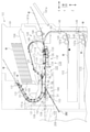
図1に示すように、印刷装置1000は、「液体」の一例であるインクを吐出し「媒体」の一例である用紙Mに画像を印刷する印刷ユニット100と、印刷ユニット100に対して用紙Mの搬送方向の下流側に配置される後処理装置500とで構成される。後処理装置500は、用紙Mの搬送方向の上流側に配置され、用紙Mに吐出されたインクを乾燥させ、搬送方向に対して斜めに搬送される斜行が補正(是正)された状態で用紙Mを送り出す中間ユニット200と、用紙Mの搬送方向の下流側に配置され、中間ユニット200から搬出された用紙Mをスタックし、用紙Mに対してステープリング処理やパンチング処理などの各種の後処理を施す後処理ユニット300とで構成される。
すなわち、印刷装置1000は、中間ユニット200及び後処理ユニット300で構成される後処理装置500と、後処理装置500に対して用紙Mの搬送方向の上流側に配置され、インクを吐出し用紙Mに画像を印刷する印刷ユニット100とを備えている。
As shown in FIG. 1, the
That is, the
印刷ユニット100は、直方体状の筐体101と、鉛直方向Zにおいて、筐体101の上部に配置された操作部102と、印刷ユニット100の中央部から下部に亘って設けられた用紙カセット103とを有している。用紙カセット103は、鉛直方向Zに4つ並んで配置され、それぞれに用紙Mが積層状態で収容されている。そして、用紙カセット103における左右方向Xの中央部には、ユーザーが把持可能な把持部103aが設けられている。最上段の用紙カセット103と隣り合う位置には、矩形状の前板カバー104が設けられている。
The
中間ユニット200は、並び方向である左右方向Xにおいて、印刷ユニット100の左側面に取り付けられている。中間ユニット200は、鉛直方向Zにおいて印刷ユニット100の側で短く、後処理ユニット300の側で長くなった筐体291を有している。筐体291には、印刷ユニット100で印刷された用紙Mが搬入される搬入口292と、後処理ユニット300へ用紙Mが搬出される搬出口293とが設けられている。
The
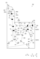
中間ユニット200は、図中の一点鎖線で示された、用紙Mが搬送される搬送経路201を有している。搬送経路201は、搬入口292と搬出口293との間に配置されている。搬送経路201には、第5搬送ローラー対群250と、第4搬送ローラー対群240及び第3搬送ローラー対群230と、第2搬送ローラー対群220と、第1搬送ローラー対群210と、補正ローラー対260と、排出ローラー対270とが、用紙Mの搬送方向に沿って順に配置されている。搬入口292から搬入された用紙Mは、第5搬送ローラー対群250と、第4搬送ローラー対群240または第3搬送ローラー対群230と、第2搬送ローラー対群220と、第1搬送ローラー対群210と、補正ローラー対260と、排出ローラー対270とによって搬送方向に搬送され、搬出口293から後処理ユニット300に搬出される。
The
第1搬送ローラー対群210は、補正ローラー対260に対して用紙Mの搬送方向上流側に配置され、同じモーター(図示省略)で駆動される複数の第1搬送ローラー対10を有している。第2搬送ローラー対群220は、第1搬送ローラー対群210に対して用紙Mの搬送方向の上流側に配置され、同じモーター(図示省略)で駆動される複数の第2搬送ローラー対20を有している。第3搬送ローラー対群230は、第2搬送ローラー対群220に対して用紙Mの搬送方向の上流側に配置され、同じモーター(図示省略)で駆動される複数の第3搬送ローラー対30を有している。第4搬送ローラー対群240は、第2搬送ローラー対群220に対して用紙Mの搬送方向の上流側に配置され、同じモーター(図示省略)で駆動される複数の第4搬送ローラー対40を有している。第5搬送ローラー対群250は、第3搬送ローラー対群230及び第4搬送ローラー対群240に対して用紙Mの搬送方向の上流側に配置され、同じモーター(図示省略)で駆動される複数の第5搬送ローラー対50を有している。
The first transport
補正ローラー対260は、搬出口293近くで、第1搬送ローラー対群210に対して用紙Mの搬送方向の下流側に配置され、用紙Mが搬送方向に対して斜めに搬送されるという用紙Mの斜行を是正する。
さらに、第1搬送ローラー対群210と第2搬送ローラー対群220との間の距離L2は、第1搬送ローラー対群210と補正ローラー対260との間の距離L1よりも長い。
The
Further, the distance L2 between the first transport
後処理ユニット300は、並び方向である左右方向Xにおいて中間ユニット200の左側面に取り付けられ、直方体状の筐体301を有している。さらに、後処理ユニット300は、図中の一点鎖線で示された用紙Mの搬送方向に沿って順に配置された、後処理用搬送ローラー対群327と、ガイド部330と、スタッカー328と、排紙ローラー対329と、排紙トレイ331とを有している。
後処理用搬送ローラー対群327は、搬出口293の近くに配置される後処理用第1搬送ローラー対327Aと、排紙ローラー対329の近くに配置される後処理用第2搬送ローラー対327Bとで構成される。すなわち、搬出口293から排紙ローラー対329に向かう方向に、後処理用第1搬送ローラー対327Aと後処理用第2搬送ローラー対327Bとが順に配置されている。
なお、後処理用第1搬送ローラー対327Aは、「載置部側搬送ローラー対」の一例である。
The
The post-treatment transfer
The post-treatment first
中間ユニット200から搬出された用紙Mは、排紙ローラー対329とガイド部330とを介して、スタッカー328に搬送される。
スタッカー328は、後処理部325で処理される用紙Mを一時的に載置するためのものであり、「載置部」の一例である。スタッカー328は、後処理部325に向かって下向きに傾斜するように斜めに配置されている。これにより、スタッカー328に載置された用紙Mの一端辺はスタッカー328の壁面328bに接触し、用紙Mの一端辺が揃えられる。スタッカー328に載置された用紙Mが所定枚数に達すると、後処理部325は、用紙Mに対してステープリング処理やパンチング処理などの各種の後処理を施す。続いて、排紙ローラー対329が駆動し、後処理が施された用紙Mは、排紙トレイ331に排出される。
このように、後処理ユニット300では、中間ユニット200から搬出された用紙Mが、排紙ローラー対329とガイド部330とによってスタッカー328に順次搬送され、スタッカー328に所定枚数の用紙Mが載置されると、後処理部325によって後処理が施され、排紙ローラー対329の駆動により排紙トレイ331に排出される。
The paper M carried out from the
The
In this way, in the
「印刷ユニットの概要」
図2は、印刷ユニットの概要を示す概略図である。
次に、図2を参照し、印刷ユニット100の概要について説明する。
図2に示すように、印刷ユニット100の筐体101内には、用紙Mに対して鉛直方向Zの上側から印刷を行う印刷部110と、用紙Mを搬送経路120に沿って搬送する搬送部130とが設けられている。搬送経路120は、前後方向Yに沿う方向を用紙Mの幅方向としたときに、この幅方向と交差する方向を搬送方向として用紙Mが搬送されるように形成されている。
"Overview of printing unit"
FIG. 2 is a schematic view showing an outline of the printing unit.
Next, the outline of the
As shown in FIG. 2, in the
印刷部110は、用紙Mの幅方向の略全域に亘って同時にインクを吐出可能なラインヘッド型の印刷ヘッド111を下部に備えている。印刷部110では、印刷ヘッド111から吐出されるインクが、印刷ヘッド111と対向する用紙Mの印刷面(画像を印刷される面)に付着(着弾)することで、用紙Mに画像が形成される。
The
搬送部130は、搬送経路120に沿って配置されている複数の搬送ローラー対131と、印刷部110の直下に設けられるベルト搬送部132とを有している。すなわち、ベルト搬送部132によって搬送されている用紙Mに対して、印刷ヘッド111からインクが吐出され、印刷が行われる。
The
インクは、色材が水系媒体に分散された(または溶解された)水性インクである。
色材は、例えば染料であり、直接染料、酸性染料、食用染料、塩基性染料、反応性染料、分散染料、建染染料、可溶性建染染料、反応分散染料などを使用することができる。
The ink is a water-based ink in which the coloring material is dispersed (or dissolved) in an aqueous medium.
The coloring material is, for example, a dye, and direct dyes, acidic dyes, edible dyes, basic dyes, reactive dyes, disperse dyes, building dyes, soluble building dyes, reaction dispersion dyes and the like can be used.
色材は、例えば顔料であり、不溶性アゾ顔料、縮合アゾ顔料、アゾレーキ、キレートアゾ顔料などのアゾ顔料、フタロシアニン顔料、ペリレン及びペリノン顔料、アントラキノン顔料、キナクリドン顔料、ジオキサン顔料、チオインジゴ顔料、イソインドリノン顔料、キノフタロン顔料などの多環式顔料、染料キレート、染色レーキ、ニトロ顔料、ニトロソ顔料、アニリンブラック、昼光蛍光顔料、カーボンブラック、卑金属顔料などを使用することができる。 The coloring material is, for example, a pigment, and is an azo pigment such as an insoluble azo pigment, a condensed azo pigment, an azo lake, a chelate azo pigment, a phthalocyanine pigment, a perylene and a perinone pigment, an anthraquinone pigment, a quinacridone pigment, a dioxane pigment, a thioindigo pigment, and an isoindolinone pigment. , Polycyclic pigments such as quinophthalone pigments, dye chelate, dyeing lakes, nitro pigments, nitroso pigments, aniline blacks, daylight fluorescent pigments, carbon blacks, base metal pigments and the like can be used.
溶剤は、例えば水系媒体であり、イオン交換水、限外ろ過水、逆浸透水、蒸留水などの純水または超純水を使用することができる。また、紫外線照射又は過酸化水素の添加などによって滅菌された水を用いると、インクを長期保存する場合にカビやバクテリアの発生を防止することができる。
なお、溶剤は、例えばエチレングリコールやプロピレングリコールなどの揮発性の水溶性有機溶剤を含んでいてもよい。
The solvent is, for example, an aqueous medium, and pure water such as ion-exchanged water, ultrafiltered water, reverse osmosis water, and distilled water or ultrapure water can be used. Further, when water sterilized by irradiation with ultraviolet rays or addition of hydrogen peroxide is used, it is possible to prevent the growth of mold and bacteria when the ink is stored for a long period of time.
The solvent may contain a volatile water-soluble organic solvent such as ethylene glycol or propylene glycol.
さらに、インクは、上述した色材や溶剤の他に、塩基性触媒、界面活性剤、第三級アミン、樹脂類、pH調整剤、緩衝液、定着剤、防腐剤、酸化防止剤・紫外線吸収剤、キレート剤、酸素吸収剤などを含んでいてもよい。 Furthermore, in addition to the above-mentioned coloring materials and solvents, inks include basic catalysts, surfactants, tertiary amines, resins, pH regulators, buffers, fixing agents, preservatives, antioxidants and UV absorbers. It may contain agents, chelating agents, oxygen absorbers and the like.
ベルト搬送部132は、印刷ヘッド111よりも搬送方向上流側に配置されている駆動ローラー133と、印刷ヘッド111よりも搬送方向下流側に配置されている従動ローラー134と、これらの各ローラー133,134に掛けられた無端状をなす環状のベルト135とを有している。駆動ローラー133が駆動回転することによりベルト135が周回し、その周回するベルト135によって用紙Mが下流側へ搬送される。すなわち、ベルト135の外表面が、印刷が行われる用紙Mを支持する支持面として機能する。
The
搬送経路120は、印刷部110へ向けて用紙Mが搬送される供給経路140と、印刷部110により印刷が行われ、印刷済とされた用紙Mが搬送される排出経路150と、排出経路150から分岐する分岐経路160とを有している。
The
供給経路140は、第1供給経路141と、第2供給経路142と、第3供給経路143とを有している。第1供給経路141では、筐体101の右側面に備えられたカバー141aを開けることによって露出する挿入口141bから挿入される用紙Mが印刷部110へ搬送される。すなわち、挿入口141bから挿入された用紙Mは、第1駆動ローラー対144の回転駆動によって印刷部110へ向かって直線的に搬送される。
The
第2供給経路142では、鉛直方向Zにおいて、筐体101の下部に備えられた用紙カセット103にそれぞれ収容された用紙Mが、印刷部110へ搬送される。すなわち、用紙カセット103に積層状態で収容された用紙Mは、最上位の用紙Mがピックアップローラー142aにより送り出され、分離ローラー対145で一枚ずつに分離された後、鉛直方向Zにおける姿勢が反転されながら、第2駆動ローラー対146の回転駆動によって印刷部110へ向かって搬送される。
In the
第3供給経路143では、用紙Mに対して両面に画像を印刷する両面印刷を行う場合に、印刷部110によって片面が印刷済とされた用紙Mが、再び印刷部110へ搬送される。すなわち、印刷部110よりも搬送方向下流側には、排出経路150から分岐する分岐経路160が設けられている。すなわち、両面印刷を行う際、用紙Mは、排出経路150の途中に設けられた分岐機構147の動作によって分岐経路160へ搬送される。また、分岐経路160には、正転と逆転の双方の回転が可能な分岐経路ローラー対161が分岐機構147よりも下流側に設けられている。
In the
両面印刷に際して、一面が印刷された用紙Mは、分岐機構147により一旦この分岐経路160へ案内され、正転する分岐経路ローラー対161によって分岐経路160内を下流側に搬送される。その後、分岐経路160へ搬送された用紙Mは、逆転する分岐経路ローラー対161によって分岐経路160内を下流側から上流側へ逆搬送される。すなわち、分岐経路160を搬送される用紙Mは搬送の向きが反転される。
In double-sided printing, the paper M on which one side is printed is once guided to the
分岐経路160から逆搬送される用紙Mは第3供給経路143へ搬送され、複数の搬送ローラー対131によって印刷部110へ向かって搬送される。第3供給経路143を搬送されることによって、用紙Mは印刷されていない他面が印刷部110と対向するように反転され、第3駆動ローラー対148の回転駆動によって印刷部110へ向かって搬送される。すなわち、第3供給経路143は、鉛直方向Zにおける用紙Mの姿勢を反転させながら搬送する反転搬送経路として機能する。
The paper M reversely conveyed from the
各供給経路141,142,143のうち、第2供給経路142及び第3供給経路143は、鉛直方向Zにおいて用紙Mの姿勢が湾曲されながら印刷部110へ向けて用紙Mが搬送される。その一方で、第1供給経路141は、第2供給経路142及び第3供給経路143と比較して、用紙Mの姿勢が大きく湾曲されることなく印刷部110へ向けて用紙Mが搬送される。
Of the
印刷部110により片面又は両面に印刷が行われ、印刷が完了した用紙Mは、搬送ローラー対131により搬送経路120の下流部を構成する排出経路150に沿って搬送される。排出経路150は、分岐経路160と分岐する位置よりも下流となる位置で、第1排出経路151、第2排出経路152、第3排出経路153に分岐している。すなわち、印刷が完了された用紙Mは、排出経路150の上流部を構成する共通排出経路(上流排出経路)154を搬送された後、共通排出経路154の下流端に設けられた案内機構(切替案内部)180により、排出経路150の下流部を構成する第1~第3の各排出経路(下流排出経路)151,152,153のうち何れかの経路へ案内される。
Printing is performed on one side or both sides by the
第1排出経路(上方排出経路)151は、筐体101の上方へ向かうとともに、分岐経路160に沿うように湾曲して延びて設けられている。第1排出経路151を搬送される用紙Mは、第1排出経路151の終端となるように筐体101の一部に開口する排出口155から排出される。そして、排出口155から排出された用紙Mは、鉛直方向Z下側へ落下し、図2において二点鎖線で示すように、積層された状態で載置台156に排紙される。なお、排出経路150の複数箇所に配置された搬送ローラー対131により、用紙Mは、排出口155から片面印刷時における印刷面が鉛直方向Zにおいて下を向く姿勢にて載置台156に排紙される。
The first discharge path (upper discharge path) 151 is provided so as to go upward of the
載置台156は、左右方向Xにおける右方向に向かうにつれて、鉛直方向Z上側に上昇する先上がりの傾斜した形状を有し、この載置台156に用紙Mが積層状態で載置される。このとき、載置台156に載置された各用紙Mは、載置台156の傾斜に沿って左方向に移動し、筐体101の排出口155の下側に設けられた縦側壁157に接近して載置される。
The mounting table 156 has an inclined shape that rises upward in the vertical direction Z toward the right in the left-right direction X, and the paper M is placed on the mounting table 156 in a laminated state. At this time, each paper M mounted on the mounting table 156 moves to the left along the inclination of the mounting table 156 and approaches the
また、第1排出経路151は、印刷部110により印刷された用紙Mが排出口155まで搬送される間において、その用紙Mの表裏を反転させる排出反転経路151aを有している。すなわち、排出反転経路151aは、印刷部110により印刷された用紙Mの印刷面を内側にして湾曲させるとともに、その用紙Mの印刷面が鉛直方向Zにおいて鉛直方向Z上側に向く状態から鉛直方向Z下側に向く状態に用紙Mを反転させる。したがって、排出経路150では、用紙Mは、この排出反転経路151aを通ることによって片面印刷時における印刷面が載置台156と対峙する状態となって排出口155から排出される。
Further, the
第2排出経路152は、第1排出経路151よりも鉛直方向Z下側に分岐し、印刷部110から筐体101の一部を形成する引出面部106に向かって直線的に延びている。そのため、第2排出経路152を搬送される用紙Mは、第1排出経路151のように湾曲した姿勢で搬送されず、その姿勢が印刷部110を通過したときと同様に一定に保たれたまま直線的に搬送され、引出面部106に形成された排出口108から引出面部106に取り付けられた排紙トレイ109に排出される。すなわち、第2排出経路152は、鉛直方向における用紙Mの姿勢を反転させることなく排紙トレイ109へ向けて用紙Mを搬送する非反転排出経路として機能する。
The
第3排出経路(下方排出経路)153は、第2排出経路152よりも鉛直方向Z下側に分岐し、筐体101の下方へ向かうように、鉛直方向Zにおいて斜め下側に向かって延びている。そして、その下流端は、中間ユニット200の搬入口292に接続されている。すなわち、第3排出経路153を搬送される用紙Mは、搬入口292から中間ユニット200の中に搬入される。
The third discharge path (downward discharge path) 153 branches downward in the vertical direction Z from the
「中間ユニットの概要」
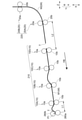
図3は、図1に示された中間ユニットの概略図に対応する図であり、中間ユニットの搬送系の状態を示す概略図である。図4は、駆動ローラーの概要を示す概略図である。図5は駆動ローラーの部分拡大図である。図6は従動ローラーの概要を示す部分概略図である。図7は、図6の一点鎖線で囲まれた領域Rの部分拡大図である。図8は、補正ローラー対の概要を示す概略図である。
なお、図3乃至図8では、説明に不要な構成要素の図示が省略されている。また、図3では、モーターによって駆動される駆動ローラー10a,20a,30a,40a,50a,260a,270aが大きな円で図示され、従動回転する従動ローラー10b,20b,30b,40b,50b,260b,270bが小さな円で図示されている。
次に、図3乃至図8を参照し、中間ユニット200の概要を説明する。
"Overview of intermediate units"
FIG. 3 is a diagram corresponding to the schematic diagram of the intermediate unit shown in FIG. 1, and is a schematic diagram showing the state of the transport system of the intermediate unit. FIG. 4 is a schematic view showing an outline of the drive roller. FIG. 5 is a partially enlarged view of the drive roller. FIG. 6 is a partial schematic view showing an outline of the driven roller. FIG. 7 is a partially enlarged view of the region R surrounded by the alternate long and short dash line of FIG. FIG. 8 is a schematic view showing an outline of a pair of correction rollers.
It should be noted that in FIGS. 3 to 8, the illustration of components unnecessary for explanation is omitted. Further, in FIG. 3, the
Next, the outline of the
図3に示すように、搬送経路201は、用紙Mの搬送経路が分岐する分岐点A及び分岐点B及び分岐点Cと、用紙Mの搬送経路が合流する合流点Dと、用紙Mの搬送経路の末端をなす端E及び端Fとを有する。また、分岐点Aと分岐点Bと分岐点Cとには、用紙Mの搬送経路を振り分ける案内フラップ(図示省略)が設けられている。
As shown in FIG. 3, the
さらに、搬送経路201は、導入経路202と、第1分岐経路203と、第1スイッチバック経路204と、第1合流経路205と、第2分岐経路206と、第2スイッチバック経路207と、第2合流経路208と、導出経路209とで構成される。
Further, the
搬入口292と分岐点Aとの間の搬送経路201が、導入経路202である。分岐点Aと分岐点Bとの間の搬送経路201が、第1分岐経路203である。分岐点Bと端Eとの間の搬送経路201が、第1スイッチバック経路204である。分岐点Bと合流点Dとの間の搬送経路201が、第1合流経路205である。分岐点Aと分岐点Cとの間の搬送経路201が、第2分岐経路206である。分岐点Cと端Fとの間の搬送経路201が、第2スイッチバック経路207である。分岐点Cと合流点Dとの間の搬送経路201が、第2合流経路208である。合流点Dと搬出口293との間の搬送経路201が、導出経路209である。
The
導入経路202と第1分岐経路203と第2分岐経路206とには、第5搬送ローラー対群250が設けられ、第5搬送ローラー対群250によって用紙Mの搬送が制御される。第1スイッチバック経路204には、第3搬送ローラー対群230が設けられ、第3搬送ローラー対群230によって用紙Mの搬送が制御される。第2スイッチバック経路207には、第4搬送ローラー対群240が設けられ、第4搬送ローラー対群240によって用紙Mの搬送が制御される。第1合流経路205と、第2合流経路208と、導出経路209における用紙Mの搬送方向の上流側とには、第2搬送ローラー対群220が設けられ、第2搬送ローラー対群220によって用紙Mの搬送が制御される。導出経路209における用紙Mの搬送方向の下流側には、第1搬送ローラー対群210と補正ローラー対260と排出ローラー対270とが設けられ、第1搬送ローラー対群210と補正ローラー対260と排出ローラー対270とによって、用紙Mの搬送が制御される。
A fifth transfer
詳細は後述するが、搬送経路201において、搬送方向に対する用紙Mの斜行が生じた場合、補正ローラー対260は用紙Mの斜行を補正(是正)する。また、斜行が是正された用紙Mは、補正ローラー対260によってニップされ、搬出口293に送り出される(搬送される)。
補正ローラー対260は、第1搬送ローラー対群210に対して搬送方向の下流側に位置し、補正ローラー対260により用紙Mをニップして搬送中に、用紙Mの先端T(図11参照)が搬出口293に到達するように配置されている。用紙Mの搬送方向の長さは、搬送経路201の長さと比べて極めて短いので、補正ローラー対260により用紙Mをニップして搬送中に、用紙Mの先端Tが搬出口293に到達するように、補正ローラー対260が配置されている状態は、補正ローラー対260が搬出口293の近くに配置されている状態に対応する。
すなわち、補正ローラー対260は、第1搬送ローラー対群210に対して搬送方向の下流側に位置し、搬出口293の近くに配置されている。
本実施形態では、搬送方向の長さが異なる複数種類の用紙Mが存在する場合、いずれの用紙Mにおいても、補正ローラー対260によりニップされて搬送中に、用紙Mの先端Tが搬出口293に到達するように、補正ローラー対260が配置されている。すなわち、搬送方向の長さが異なる複数種類の用紙Mが存在し、搬送方向の長さが最も短い用紙Mにおいても、補正ローラー対260によりニップされて搬送中に、当該用紙Mの先端Tが搬出口293に到達するように、補正ローラー対260が配置されている。
Although the details will be described later, when the skew of the paper M with respect to the transport direction occurs in the
The
That is, the
In the present embodiment, when there are a plurality of types of paper M having different lengths in the transport direction, the tip T of the paper M is 293 at the carry-out
第3搬送ローラー対群230及び第4搬送ローラー対群240は正転方向または逆転方向に回転可能であり、第1スイッチバック経路204及び第2スイッチバック経路207において用紙Mの搬送方向を反転させることができる。
The third transfer
第1搬送ローラー対群210に配置される第1搬送ローラー対10は、第1駆動ローラー10aと第1従動ローラー10bとで構成される。第2搬送ローラー対群220に配置される第2搬送ローラー対20は、第2駆動ローラー20aと第2従動ローラー20bとで構成される。第3搬送ローラー対群230に配置される第3搬送ローラー対30は、第3駆動ローラー30aと第3従動ローラー30bとで構成される。第4搬送ローラー対群240に配置される第4搬送ローラー対40は、第4駆動ローラー40aと第4従動ローラー40bとで構成される。第5搬送ローラー対群250に配置される第5搬送ローラー対50は、第5駆動ローラー50aと第5従動ローラー50bとで構成される。
排出ローラー対270は、駆動ローラー270aと従動ローラー270bとで構成される。
The first
The
なお、第1駆動ローラー10aと第2駆動ローラー20aと第3駆動ローラー30aと第4駆動ローラー40aと第5駆動ローラー50aと駆動ローラー270aとは、同じ構成を有している。このため、第1駆動ローラー10aを代表して説明し、駆動ローラー20a,30a,40a,50a,270aの説明を省略する。
第1従動ローラー10bと第2従動ローラー20bと第3従動ローラー30bと第4従動ローラー40bと第5従動ローラー50bと従動ローラー270bとは、同じ構成を有している。このため、第1従動ローラー10bを代表して説明し、従動ローラー20b,30b,40b,50b,270bの説明を省略する。
さらに、以降の説明では、駆動ローラー20a,30a,40a,50aをまとめて駆動ローラー1と称し、従動ローラー20b,30b,40b,50bをまとめて従動ローラー2と称する場合がある。
The
The first driven
Further, in the following description, the
第1搬送ローラー対10では、第1駆動ローラー10aと第1従動ローラー10bとが用紙Mをニップし(挟み)、第1駆動ローラー10aの動力源であるモーターが駆動することで、第1駆動ローラー10aが回転駆動し、用紙Mを搬送方向に搬送させる力が用紙Mに付与される。第1従動ローラー10bは、第1駆動ローラー10aとの間で用紙Mをニップし従動回転する。
In the first
印刷ユニット100において用紙Mの片方の面に画像が印刷されている場合、第1従動ローラー10bは画像が形成された片方の面に接し、第1駆動ローラー10aは画像が形成されていない面に接する。印刷ユニット100において用紙Mの両方の面に画像が印刷されている場合、第1従動ローラー10bは後で画像が形成された面に接し、第1駆動ローラー10aは先に画像が形成された面に接する。
When an image is printed on one side of the paper M in the
以降の説明では、用紙Mの片方の面に画像が印刷されている場合の画像が形成された片方の面、及び用紙Mの両方の面に画像が印刷されている場合の後で画像が形成された面を、用紙Mの表面と称す。用紙Mの片方の面に画像が印刷されている場合の画像が形成されていない面、及び用紙Mの両方の面に画像が印刷されている場合の先に画像が形成された面を、用紙Mの裏面と称す。
すなわち、第1従動ローラー10bは用紙Mの表面に接し、第1駆動ローラー10aは用紙Mの裏面に接する。
In the following description, the image is formed after the image is printed on one side of the paper M and the image is formed on both sides of the paper M. The surface that has been printed is referred to as the surface of the paper M. Paper is the side on which the image is not formed when the image is printed on one side of the paper M, and the side on which the image is formed earlier when the image is printed on both sides of the paper M. It is called the back side of M.
That is, the first driven
第1駆動ローラー10aは、用紙Mの想定最大幅よりも長く、用紙Mの幅方向の全域で用紙Mの裏面に接触する。図4及び図5に示すように、第1駆動ローラー10aは、一方向に伸びた円筒形状を有し、駆動軸11と、駆動軸11に挿通されるゴムローラー部12と、ゴムローラー部12を覆う粗面部13とを有し、粗面部13が用紙Mの裏面に接する。ゴムローラー部12は、駆動軸11に固定され、駆動軸11と一体回転可能に設けられている。粗面部13は、ゴムローラー部12を覆う結合剤層14と、結合剤層14の表面から突出するよう埋め込まれたセラミック粒子15とで構成される。
The
第1駆動ローラー10aの用紙Mに接する外周面に、粗面部13を設けることによって、セラミック粒子15が用紙Mの裏面に食い込むように配置されるので、用紙Mに対して安定して搬送方向の力が付与され、用紙Mが安定して搬送されるようになる。すなわち、セラミック粒子15が用紙Mの裏面に食い込むことにより、第1駆動ローラー10aは用紙Mに対して滑りにくくなるので、第1駆動ローラー10aから用紙Mに対して安定して搬送方向の力が付与され、用紙Mが安定して搬送されるようになる。
By providing the
さらに、セラミック粒子15が用紙Mの裏面に点接触するので、第1駆動ローラー10aの用紙Mに対する接触面積が狭くなり、例えば用紙Mに両面印刷がなされ、用紙Mの裏面に未乾燥のインクが残存する場合、当該未乾燥のインクが第1駆動ローラー10aに転写しにくくなり、第1駆動ローラー10aが汚れにくくなる。
Further, since the
第1従動ローラー10bは、複数のロール体(ロール部17)に分割されている。このため、第1従動ローラー10bの用紙Mに接する部分の面積は、第1駆動ローラー10aの用紙Mに接する部分の面積よりも狭くなっている。
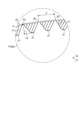
図6では、第1従動ローラー10bの複数のロール体(ロール部17)の一つが図示されている。図6に示すように、第1従動ローラー10bは、従動軸16と、従動軸16に挿通されるロール部17とを含んで構成されている。詳しくは、第1従動ローラー10bは、従動軸16と、従動軸16に挿通される複数のロール部17とを含んで構成されている。ロール部17は、従動軸16に固定され、従動軸16と一体回転可能に設けられている。ロール部17は、6つの歯付プレート82を有している。
The first driven
In FIG. 6, one of a plurality of roll bodies (roll portions 17) of the first driven
図7は、領域Rを従動軸16に沿った方向(Y方向)から見た部分拡大図であり、ロール部17(6つの歯付プレート82)の周面に設けられた歯77の状態が図示されている。
図7に示すように、Y方向から見た場合、ロール部17(6つの歯付プレート82)の周面において、それぞれの歯77が完全に重ならないよう、歯77の位置がずれて設けられている。すなわち、Y方向から見た場合、全ての歯77が視認可能となるように、ロール部17の周面に歯77が配置されている。
詳しくは、Y方向から見た場合、ロール部17の周方向における歯77と歯77の間隔が、等間隔となるように配置されている。すなわち、一の歯付プレート82が有する歯77と歯77のピッチPを六等分するように、他の五枚の歯付プレート82の歯77が配置されている。なお、本実施形態では、歯77と歯77のピッチPの長さは、概略0.6mmである。
そして、6つ歯付プレート82の周面に設けられた歯77の先端が用紙Mに点接触する。すなわち、第1従動ローラー10b(ロール部17)は、表面の外側に向けて尖った歯77を備え、歯77が用紙Mの表面に対して点接触する。
なお、第1従動ローラー10bに設けられた歯77は、「点接触可能な凸部」の一例である。すなわち、第1従動ローラー10bは、用紙Mに対して点接触可能な凸部(歯77)が設けられた表面を有し、用紙Mの表面に接する。
FIG. 7 is a partially enlarged view of the region R as viewed from the direction (Y direction) along the driven
As shown in FIG. 7, when viewed from the Y direction, the
Specifically, when viewed from the Y direction, the distance between the
Then, the tips of the
The
また、歯付プレート82において、歯77の先端を山部分90とすると、山部分90と山部分90の間には溝状の谷部分91が設けられる。本実施形態では、ロール部17の径方向において、歯77の谷部分91から山部分90までの距離L3は、概略0.41mmである。また、用紙Mに点接触する歯77の形状は、その先端角度が45度以上となる三角形状であることが好ましく、本実施形態ではその山部分90の角度が60度となるように構成されている。
Further, in the
このように、歯77は、表面の外側に向けて尖った形状を有し、セラミック粒子15と比べて用紙Mに対する接触面積をさらに狭くすることができる。用紙Mに両面印刷を施した場合、用紙Mの表面には、用紙Mの裏面と比べて未乾燥のインクが残留しやすい。用紙Mの表面に未乾燥のインクが多く存在する場合であっても、第1従動ローラー10bは、第1駆動ローラー10aと比べて、用紙Mに対する接触面積が狭くなっているので、当該未乾燥のインクが第1従動ローラー10bに転写しにくくなり、第1従動ローラー10bが汚れにくくなる。
As described above, the
さらに、表面の外側に向けて尖った歯77が用紙Mの表面に食い込むことによって、第1従動ローラー10bは、用紙Mに対して滑りにくくなり、第1駆動ローラー10aとの間で用紙Mをニップし、安定して従動回転することができる。
Further, the
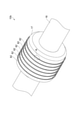
図8に示すように、補正ローラー対260は、駆動ローラー260aと従動ローラー260bとで構成される。駆動ローラー260aは、動力源であるモーターが駆動することで回転駆動する。従動ローラー260bは、駆動ローラー260aとの間で用紙Mをニップし従動回転する。すなわち、補正ローラー対260は、用紙Mを搬出口293に向けて搬送する方向に回転駆動する駆動ローラー260aと、駆動ローラー260aとの間で用紙Mをニップし従動回転する従動ローラー260bとを有している。
なお、駆動ローラー260aは「第1ローラー」の一例であり、従動ローラー260bは「第2ローラー」の一例である。
As shown in FIG. 8, the
The
駆動ローラー260aは用紙Mの表面に接し、従動ローラー260bは用紙Mの裏面に接する。すなわち、従動ローラー20b,30b,40b,50b,270bと駆動ローラー260aとは用紙Mの表面に接し、駆動ローラー20a,30a,40a,50a,270aと従動ローラー260bとは用紙Mの裏面に接する。
The
なお、従動ローラー260bが用紙Mの表面に接し、駆動ローラー260aが用紙Mの裏面に接する構成であってもよい。すなわち、従動ローラー20b,30b,40b,50b,270bと従動ローラー260bとが用紙Mの表面に接し、駆動ローラー20a,30a,40a,50a,270aと駆動ローラー260aとが用紙Mの裏面に接する構成であってもよい。
The driven
駆動ローラー260aは、駆動軸264と、この駆動軸264に挿通される複数のローラー265とを含んで構成されている。ローラー265は、駆動軸264に固定され、駆動軸264と一体回転可能に設けられている。ローラー265は、第1搬送ローラー対10における第1従動ローラー10bのロール部17(図6参照)と同じ構成を有している。すなわち、ローラー265の表面には、表面の外側に向けて尖った歯77(図7参照)を備え、歯77が用紙Mの表面に対して点接触する。
このように、駆動ローラー260aは、用紙Mに対して点接触可能な歯77が設けられた表面を有している。また、Y方向から見た場合、駆動ローラー260a(ロール部17)の周面においてそれぞれの歯77が完全に重ならないよう、歯77の位置がずれて設けられている(図7参照)。
なお、駆動ローラー260aに設けられた歯77は、「点接触可能な凸部」の一例である。すなわち、駆動ローラー260aは、用紙Mに対して点接触可能な凸部(歯77)が設けられた表面を有している。
The
As described above, the
The
その結果、駆動ローラー260aは、その表面に設けられた歯77が用紙Mの表面に食い込むことによって、用紙Mに対して滑りにくくなり、用紙Mに対して安定して搬送方向の力を付与することができ、用紙Mを安定して搬送させることができる。駆動ローラー260aは、その表面に歯77を設けることによって、汚れにくくなる。
As a result, the
従動ローラー260bは、従動軸266と、従動軸266に挿通される複数のローラー267とを含んで構成されている。ローラー267は、従動軸266に回転可能に支持され、駆動ローラー260aのローラー265と対向するように配置されている。複数のローラー267のそれぞれは、凹凸がない平滑な表面を有している。従って、用紙Mは、表面に歯77を有する駆動ローラー260aと比べて、従動ローラー260bに対して滑りやすい。
すなわち、従動ローラー260bは、用紙Mが滑りやすい平滑な表面を有している。
The driven
That is, the driven
さらに、従動ローラー260bは、耐摩耗性に優れ、滑りやすい材料で構成されている。例えば、従動ローラー260bは、ポリアセタール(アセタール樹脂)で構成され、耐摩耗性に加えて、自己潤滑性や優れた滑り性を有する。従動ローラー260bの構成材料としては、ポリアセタールの他に、ポリアミド、ポリテトラフルオロエチレン(フッ素樹脂)、及びポリフェニレンサルファイドなどを使用することができる。
Further, the driven
従動ローラー260bは、用紙Mの裏面に面接触する。
中間ユニット200に搬入された用紙Mは、第5搬送ローラー対群250と、第4搬送ローラー対群240及び第3搬送ローラー対群230と、第2搬送ローラー対群220と、第1搬送ローラー対群210とを経由して、補正ローラー対260に至る。第5搬送ローラー対群250と、第4搬送ローラー対群240及び第3搬送ローラー対群230と、第2搬送ローラー対群220と、第1搬送ローラー対群210とを経由して、用紙Mが搬送される間に、用紙Mの裏面に付着したインクは徐々に乾燥するので、従動ローラー260bに接する用紙Mの裏面には、未乾燥のインクが残留しにくい。従って、従動ローラー260bが用紙Mの裏面に面接触しても、従動ローラー260bには未乾燥のインクによる汚染が生じにくい。
The driven
The paper M carried into the
「中間ユニットの搬送経路」
図9は、用紙の搬送経路を示す概略図である。図10は、他の用紙の搬送経路を示す概略図である。
なお、図9及び図10は、図3に対応する図であり、駆動ローラー20a,30a,40a,50a,260a,270aや従動ローラー20b,30b,40b,50b,260b,270bなどの搬送経路の説明に不要な構成要素の図示が省略されている。さらに、図9及び図10では、搬送経路201のうち用紙Mの搬送で使用される部分が実線で示され、搬送経路201のうち用紙Mの搬送で使用されない部分が破線で示されている。また、図中の矢印は用紙Mの搬送方向を示し、それぞれH1~H6の符号が付されている。
"Transfer route of intermediate unit"
FIG. 9 is a schematic view showing a paper transport path. FIG. 10 is a schematic view showing a transport path of other papers.
9 and 10 are views corresponding to FIG. 3, and are of transport paths such as
図9の実線で示すように、用紙Mが搬送される第1の搬送経路201aは、導入経路202と、第1分岐経路203と、第1スイッチバック経路204と、第1合流経路205と、導出経路209とで構成される。
第1の搬送経路201aでは、搬入口292から搬入された用紙Mが、導入経路202を通過し、第1分岐経路203を搬送方向H1に進行し、第1スイッチバック経路204に搬入される。第1スイッチバック経路204に搬入された用紙Mは、搬送方向H2の方向に進行した後、用紙Mの進行方向が反転され(スイッチバックされ)、搬送方向H2と逆方向の搬送方向H3に進行し、第1合流経路205に搬入される。さらに、用紙Mは、第1合流経路205において搬送方向H4に進行し、導出経路209に搬入され、導出経路209において搬送方向H5及び搬送方向H6に進行し、搬出口293から後処理ユニット300に向けて搬出される。
As shown by the solid line in FIG. 9, the
In the
図10の実線で示すように、用紙Mが搬送される他の搬送経路201b(第2の搬送経路201b)は、導入経路202と、第2分岐経路206と、第2スイッチバック経路207と、第2合流経路208と、導出経路209とで構成される。
第2の搬送経路201bでは、搬入口292から搬入された用紙Mは、導入経路202を通過し、第2分岐経路206を搬送方向H1に進行し、第2スイッチバック経路207に搬入される。第2スイッチバック経路207に搬入された用紙Mは、搬送方向H2に進行した後、用紙Mの進行方向が反転され(スイッチバックされ)、搬送方向H2と逆方向の搬送方向H3に進行し、第2合流経路208に搬入される。さらに、用紙Mは、第2合流経路208において搬送方向H4に進行し、導出経路209に搬入され、導出経路209において搬送方向H5及び搬送方向H6に進行し、搬出口293から後処理ユニット300に向けて搬出される。
As shown by the solid line in FIG. 10, the
In the
搬入口292から搬入された用紙Mは、分岐点Aに設けられた案内フラップによって第1の搬送経路201aに案内される。続いて、搬入口292から搬入された次の用紙Mは、分岐点Aに設けられた案内フラップによって、第2の搬送経路201bに案内される。そして、第1の搬送経路201aによる用紙Mの搬送と、第2の搬送経路201bによる用紙Mの搬送とが交互に繰り返される。
中間ユニット200は、二つの搬送経路(第1の搬送経路201a、第2の搬送経路201b)を有しているので、一つの搬送経路を有している場合と比べて、用紙Mの搬送能力を高めることができる。
The paper M carried in from the carry-in
Since the
搬送経路201a,201bは、スイッチバック経路204,207を有しているので、スイッチバック経路204,207を有していない場合と比べて、搬送経路201a,201bを長くすることができる。すなわち、本実施形態に係る中間ユニット200は、省スペース化を図りつつ、用紙Mの搬送能力を高め、且つ搬送経路201a,201bを長くできる構成を有している。
Since the
印刷ユニット100において、印刷ヘッド111からインク(水性インク)が用紙Mに吐出され、インクが用紙Mに付着するとインク中の水分が用紙Mに浸透し、用紙Mが水分を吸収する。中間ユニット200では、用紙Mを搬送経路201a,201bで搬送させることによって、用紙Mに吸収された水分を蒸発させ、用紙Mに付着したインクを乾燥させる。搬送経路201a,201bは長くなっているので、搬送経路201a,201bが短い場合と比べて、用紙Mに付着したインクをより適正に乾燥させることができる。
このように、中間ユニット200では、用紙Mがスイッチバック経路204,207によって長くなった搬送経路201a,201bを搬送されることによって、用紙Mに付着したインクを適正に乾燥させることができる。換言すれば、搬送経路201a,201bは、用紙Mに吸収された水分を蒸発させ、用紙Mに付着したインクを適正に乾燥させる乾燥経路をなす。
In the
In this way, in the
スイッチバック経路204,207によって用紙Mの搬送方向(進行方向)がスイッチバックされ、用紙Mの進行方向が反転されると、搬送方向に対する用紙Mの表面の位置も反転される。すなわち、スイッチバック経路204,207によって用紙Mの進行方向がスイッチバックされる前後で、搬送方向に対する用紙Mの表面の位置が反転される。
When the transport direction (traveling direction) of the paper M is switched back by the
このため、搬入口292から搬入された用紙Mは、スイッチバック経路204,207によって、搬送方向に対する表面の位置が反転される。そして、搬送方向に対する表面の位置が反転された状態で、用紙Mが搬出口293から後処理ユニット300に向けて搬出される。
その結果、用紙Mは、表面が鉛直方向Zの上側に配置された状態で搬入口292から搬入され、表面が鉛直方向Zの下側に配置された状態で搬出口293から搬出される。すなわち、印刷装置1000では、表面が鉛直方向Zの上側に配置された状態で、用紙Mが印刷ユニット100から中間ユニット200に搬入され、表面が鉛直方向Zの下側に配置された状態で、用紙Mが中間ユニット200から後処理ユニット300に搬入される。
Therefore, the position of the surface of the paper M carried in from the carry-in
As a result, the paper M is carried in from the carry-in
ところが、印刷ユニット100において、印刷ヘッド111から水性インクが用紙Mに吐出され、用紙Mが水分を吸収すると、用紙Mが膨潤する。さらに、用紙Mにおける印刷デューティは均一でなく、用紙Mは、濃い画像が形成され印刷デューティが高い部分(インクの吐出量が多い部分)と、淡い画像が形成され印刷デューティが低い部分(インクの吐出量が少ない部分)とを有する。印刷デューティが高い部分では、用紙Mは多量の水分を吸収するため、用紙Mの膨潤が大きくなる。印刷デューティが低い部分では、用紙Mは少量の水分を吸収するため、用紙Mの膨潤が小さくなる。
However, in the
このため、画像が印刷された用紙Mには、膨潤が大きい部分と膨潤が小さい部分とが混在するようになり、この膨潤状態の違いによって、用紙Mがカール(湾曲)するようになる。
よって、中間ユニット200では、水分を吸収しカールした用紙Mが、搬送経路201a,201bを搬送されることになる。さらに、用紙Mのカールの状態は、印刷される画像パターンやインクの組成(水分含有量)などで変化するので、様々な状態にカールした用紙Mが、搬送経路201a,201bを搬送されることになる。
Therefore, the paper M on which the image is printed has a portion having a large swelling and a portion having a small swelling, and the paper M is curled (curved) due to the difference in the swelling state.
Therefore, in the
用紙Mにカールが生じていない場合、搬送方向の下流側に配置される用紙Mの端部(以降、先端T(図11参照)と称す)は、駆動ローラー1や従動ローラー2に対して均一に接しやすくなり、搬送方向に対する用紙Mの斜行は生じにくい。
ところが、用紙Mがカールしている場合、用紙Mの先端Tは駆動ローラー1や従動ローラー2に対して均一に接することが難しくなり、搬送方向に対する用紙Mの斜行が生じやすくなる。さらに、用紙Mの斜行の状態は、用紙Mのカールの状態によって変動し、用紙Mの斜行が軽微である場合や、用紙Mの斜行が甚大である場合が生じる。
このため、搬送方向に対して軽微に斜行した用紙Mや、搬送方向に対して甚大に斜行した用紙Mが、中間ユニット200から後処理ユニット300に搬入されることになる。
When the paper M is not curled, the end portion of the paper M arranged on the downstream side in the transport direction (hereinafter referred to as the tip T (see FIG. 11)) is uniform with respect to the
However, when the paper M is curled, it becomes difficult for the tip T of the paper M to uniformly contact the
Therefore, the paper M slightly skewed in the transport direction and the paper M significantly skewed in the transport direction are carried from the
用紙Mの斜行が甚大である場合、用紙Mが斜行した状態でスタッカー328に載置されるので、スタッカー328に載置された用紙Mに対して後処理部325が適正に後処理を施すことが難しいという不具合が生じる。
When the skew of the paper M is extremely large, the paper M is placed on the
このため、本実施形態に係る中間ユニット200では、後処理ユニット300に向けて用紙Mを搬出する搬出口293の近くに、搬送方向に対する用紙Mの斜行を是正する構成を有している。中間ユニット200は、搬送経路201a,201bを搬送することで生じた搬送方向に対する用紙Mの斜行を、搬出口293の近くで適正に是正するので、整列された状態で用紙Mはスタッカー328に載置され、後処理部325はスタッカー328に載置された用紙Mに対して適正に後処理を施すことができる。
以下に、その詳細を説明する。
Therefore, the
The details will be described below.
「用紙の斜行の是正方法」
図11は、図3における補正ローラー対が配置された部分の拡大図であり、用紙の斜行の是正を施す前の状態を示す概略図である。すなわち、図11は、第1搬送ローラー対群210によって用紙M1が補正ローラー対260の直前に搬送された状態が図示されている。
図12は、用紙の斜行の是正方法を示す工程フローである。図13は、図11の部分拡大図であり、図12に示す工程の状態を示す概略図である。図14及び図15は、図13に対応する図であり、図12に示す工程の状態を示す概略図である。
なお、図11、図13、図14、及び図15では、状態を分かりやすくするために、駆動ローラー10a,20a,260aと従動ローラー10b,20b,260bとは、同じ大きさの円で図示されている。
"How to correct paper skew"
FIG. 11 is an enlarged view of the portion of FIG. 3 in which the pair of correction rollers is arranged, and is a schematic view showing a state before correcting the skew of the paper. That is, FIG. 11 shows a state in which the paper M1 is conveyed immediately before the
FIG. 12 is a process flow showing a method for correcting skewing of paper. FIG. 13 is a partially enlarged view of FIG. 11 and is a schematic view showing a state of the process shown in FIG. 14 and 15 are diagrams corresponding to FIG. 13, and are schematic views showing the state of the process shown in FIG.
In FIGS. 11, 13, 14, and 15, the
図11に示すように、補正ローラー対260に対して、用紙Mの搬送方向H6の上流側に、第1搬送ローラー対10Aと、第1搬送ローラー対10Bと、第1搬送ローラー対10Cと、第1搬送ローラー対10Dと、第2搬送ローラー対20Aと、第2搬送ローラー対20Bとが順に配置されている。第1搬送ローラー対10Aと第1搬送ローラー対10Bと第1搬送ローラー対10Cと第1搬送ローラー対10Dとで第1搬送ローラー対群210が構成され、第2搬送ローラー対20Aと第2搬送ローラー対20Bとで第2搬送ローラー対群220の一部が構成される。
As shown in FIG. 11, the first
用紙M1は、第1搬送ローラー対群210によって搬送方向H6に搬送され、用紙M1の先端Tは、補正ローラー対260の直前に配置されている。用紙M1は搬送方向H6に対して斜めに搬送されているので、用紙M1の先端Tは、搬送方向H6に対して直交する方向に交差する。
すなわち、用紙M1の斜行が生じず、用紙M1が搬送方向H6に沿って搬送される場合、用紙M1の先端Tは、搬送方向H6に対して直交する。用紙M1の斜行が生じ、用紙M1が搬送方向H6に対して斜めに搬送される場合、用紙M1の先端Tは、搬送方向H6に対して直交する方向に交差する。
The paper M1 is transported in the transport direction H6 by the first transport
That is, when the paper M1 is not skewed and the paper M1 is transported along the transport direction H6, the tip T of the paper M1 is orthogonal to the transport direction H6. When the paper M1 is skewed and the paper M1 is transported diagonally with respect to the transport direction H6, the tip T of the paper M1 intersects in a direction orthogonal to the transport direction H6.
次の用紙M2は、第2搬送ローラー対群220によって、搬送方向H6に搬送されている。次の用紙M2の先端Tは、第2搬送ローラー対20Aから第1搬送ローラー対群210の側に張り出して配置される。
The next sheet M2 is conveyed in the conveying direction H6 by the second conveying
図12に示すように、用紙Mの斜行の是正方法は、用紙Mの先端Tを補正ローラー対260のニップ位置P1に案内する工程(ステップS1)と、ニップ位置P1において用紙Mの斜行を是正する工程(ステップS2)と、斜行が是正された用紙Mを搬出口293に向けて搬出する工程(ステップS3)とを含む。
As shown in FIG. 12, the method for correcting the skew of the paper M includes a step of guiding the tip T of the paper M to the nip position P1 of the correction roller pair 260 (step S1) and the skew of the paper M at the nip position P1. (Step S2) and a step (step S3) of carrying out the paper M whose skew has been corrected toward the carry-out
ステップS1では、補正ローラー対260(駆動ローラー260a)は停止し、第1搬送ローラー対群210(第1駆動ローラー10a)は駆動し、第1搬送ローラー対群210から用紙M1に対して搬送方向H6の力が付加されている状態にある。
図13に示すように、用紙Mは、第1搬送ローラー対群210によって搬送方向H6に搬送され、最初に用紙M1の先端Tが補正ローラー対260の従動ローラー260bの位置P2に接する。従動ローラー260bは滑りやすい材料で構成されているので、用紙M1の先端Tは、搬送方向H6の方向の力によって従動ローラー260bの平滑な表面を滑り、補正ローラー対260のニップ位置P1に案内される。
すなわち、従動ローラー260bは、平滑な表面を有し、用紙Mの斜行を是正する場合、用紙Mの先端T(用紙Mの端)を滑らせて駆動ローラー260aとの間で用紙Mをニップするニップ位置P1に案内する。
In step S1, the correction roller pair 260 (drive
As shown in FIG. 13, the paper M is transported in the transport direction H6 by the first transport
That is, the driven
ステップS2では、用紙Mの先端Tが補正ローラー対260のニップ位置P1に案内されると、第1搬送ローラー対10D、第1搬送ローラー対10C、第1搬送ローラー対10B、第1搬送ローラー対10Aの順に、第1駆動ローラー10aに対するモーターの接続を解除し、第1駆動ローラー10aが空回りする状態に変化させ、第1搬送ローラー対10A,10B,10C,10Dから用紙Mに対して付与される搬送方向H6の力を順に解除する。
In step S2, when the tip T of the paper M is guided to the nip position P1 of the
なお、第1搬送ローラー対10A及び第1搬送ローラー対10Bにおいて、第1搬送ローラー対10Aは「下流側第1搬送ローラー対」の一例であり、第1搬送ローラー対10Bは「上流側第1搬送ローラー対」の一例である。第1搬送ローラー対10B及び第1搬送ローラー対10Cにおいて、第1搬送ローラー対10Bは「下流側第1搬送ローラー対」の一例であり、第1搬送ローラー対10Cは「上流側第1搬送ローラー対」の一例である。第1搬送ローラー対10C及び第1搬送ローラー対10Dにおいて、第1搬送ローラー対10Cは「下流側第1搬送ローラー対」の一例であり、第1搬送ローラー対10Dは「上流側第1搬送ローラー対」の一例である。
すなわち、用紙Mの斜行を是正する場合、「上流側第1搬送ローラー対」から用紙Mに付与される搬送方向H6の力を先に解除し、「下流側第1搬送ローラー対」から用紙Mに付与される搬送方向H6の力を後で解除する。
In the first
That is, when correcting the skew of the paper M, the force applied to the paper M in the transport direction H6 is first released from the "upstream side first transport roller pair", and the paper is released from the "downstream side first transport roller pair". The force applied to M in the transport direction H6 is later released.
第1搬送ローラー対群210から用紙M1に対して搬送方向H6の力が付加されているので、図13の破線及び図14の実線で示すように、用紙M1は補正ローラー対260と第1搬送ローラー対10Aとの間で、左右方向Xの右側に撓み、用紙M1の先端Tが補正ローラー対260のニップ位置P1に押し込まれた状態になる。
Since the force in the transport direction H6 is applied to the paper M1 from the first transport
補正ローラー対260のニップ位置P1は、搬送方向H6に対して直交するので、用紙M1の先端Tを補正ローラー対260のニップ位置P1に押し込むと、用紙M1の先端Tは、補正ローラー対260のニップ位置P1に沿った方向、すなわち搬送方向H6に対して直交する方向に配置されるようになる。
このように、ステップS2では、用紙M1の先端Tが、搬送方向H6に対して直交する方向に交差する状態(用紙Mが斜行した状態)から、搬送方向H6に対して直交する状態(用紙Mの斜行が是正された状態)に是正される。
Since the nip position P1 of the
As described above, in step S2, the tip T of the paper M1 intersects the direction perpendicular to the transport direction H6 (the state in which the paper M is skewed) to the state orthogonal to the transport direction H6 (paper). The skew of M is corrected).
上述したように、Y方向から見た場合、駆動ローラー260aの周面においてそれぞれの歯77が完全に重ならないよう、歯77の位置がずれて設けられている(図7参照)。
仮に、Y方向から見た場合、駆動ローラー260aの周面において歯77が重なるように設けられていると、補正ローラー対260に突き当たる用紙Mの先端Tが、駆動ローラー260aの歯77と歯77の間に入り込んでしまい、補正ローラー対260のニップ位置P1に誘導されず、適正に用紙Mの斜行を是正できないという虞が生じる。
本実施形態では、それぞれの歯77が完全に重ならないように設けられているので、用紙Mの先端Tが、駆動ローラー260aの歯77と歯77の間に入り込みにくく、安定して補正ローラー対260のニップ位置P1に誘導され、適正に用紙Mの斜行を是正することができる。
As described above, when viewed from the Y direction, the
If the
In the present embodiment, since the
仮に、「下流側第1搬送ローラー対」の一例である第1搬送ローラー対10Bとモーターとの接続を先に解除し、「上流側第1搬送ローラー対」の一例である第1搬送ローラー対10Cとモーターとの接続を後で解除する場合、図15に示すように、用紙M1は、補正ローラー対260と第1搬送ローラー対10Aとの間に加えて、第1搬送ローラー対10Bと第1搬送ローラー対10Cとの間でも撓むようになり、第1搬送ローラー対10Bと第1搬送ローラー対10Cとの間で用紙M1のジャムなどの搬送不良が生じやすくなる。
従って、用紙M1の斜行を是正する場合、補正ローラー対260から遠くに配置された第1搬送ローラー対10から順に、第1搬送ローラー対10から用紙M1に対して付与される搬送方向H6の力を順に解除することが好ましい。すなわち、用紙Mの斜行を是正する場合、「上流側第1搬送ローラー対」から用紙Mに付与される搬送方向H6の力を先に解除し、「下流側第1搬送ローラー対」から用紙Mに付与される搬送方向H6の力を後で解除する構成が好ましい。
Temporarily, the connection between the first
Therefore, when correcting the skew of the paper M1, the transport direction H6 given to the paper M1 from the first
ステップS3では、駆動ローラー260aを駆動し、補正ローラー対260を回転駆動させて、斜行が是正された用紙Mを搬出口293に向けて搬出する。
続いて、次の用紙M2に対してステップS1及びステップS2を実行し、次の用紙M2の斜行を是正する。
In step S3, the
Subsequently, steps S1 and S2 are executed for the next sheet M2 to correct the skew of the next sheet M2.
図14に戻って、ステップS2では、第2搬送ローラー対群220は駆動した状態を維持している。すなわち、補正ローラー対260によって用紙M1の搬送方向H6への搬送が阻害されている間も、次の用紙M2は、第2搬送ローラー対群220によって搬送方向H6に搬送されている。
Returning to FIG. 14, in step S2, the second transport
第1搬送ローラー対群210と第2搬送ローラー対群220との間の距離L2は、第1搬送ローラー対群210と補正ローラー対260との間の距離L1よりも長く、用紙M1の搬送方向H6への搬送が阻害されている間に、次の用紙M2が搬送方向H6に搬送された場合に、次の用紙M2が用紙M1に干渉しない程度に設定されている。
従って、ステップS2において、補正ローラー対260によって用紙M1の搬送方向H6への搬送が阻害され、第2搬送ローラー対群220によって次の用紙M2が搬送方向H6に搬送される場合、次の用紙M2は、用紙M1に近付き、用紙M1に干渉しない。
The distance L2 between the first transport
Therefore, in step S2, when the
従って、ステップS2では、第2搬送ローラー対群220による用紙Mの搬送を停止する必要がないので、第2搬送ローラー対群220による用紙Mの搬送を停止する場合と比べて、搬送経路201における用紙Mの搬送能力を高めることができる。
従って、第1搬送ローラー対群210と第2搬送ローラー対群220との間の距離L2は、補正ローラー対260と第1搬送ローラー対群210との間の距離L1よりも長い構成が好ましい。
Therefore, in step S2, it is not necessary to stop the transfer of the paper M by the second transfer
Therefore, it is preferable that the distance L2 between the first transport
上述したように、補正ローラー対260は、補正ローラー対260により用紙Mをニップして搬送中に用紙Mの先端Tが搬出口293に到達するように、搬出口293の近くに配置されている。その結果、搬送経路201a,201bを搬送することで生じた用紙Mの斜行は、補正ローラー対260によって、搬出口293の近くで是正される。従って、斜行が是正された用紙Mが搬出口293から後処理ユニット300に搬入され、後処理ユニット300において用紙Mが整列された状態でスタッカー328に載置され、後処理部325はスタッカー328に載置された用紙Mに対して適正に後処理を施すことができる。
As described above, the
さらに、補正ローラー対260は、補正ローラー対260により用紙Mをニップして搬送中に、用紙Mの先端Tが後処理用第1搬送ローラー対327Aに到達するように配置されている。換言すれば、補正ローラー対260により斜行が是正された用紙Mをスタッカー328(後処理部325)に向けて搬送する場合、補正ローラー対260及び後処理用第1搬送ローラー対327Aの両方で用紙Mをニップできるような距離に、補正ローラー対260が配置されている。
詳しくは、搬送方向の長さが異なる複数種類の用紙Mが存在し、搬送方向の長さが最も短い用紙Mにおいても、補正ローラー対260及び後処理用第1搬送ローラー対327Aの両方で用紙Mをニップできるような距離に、補正ローラー対260が配置されている。例えば、用紙MのサイズがA4サイズであり、用紙Mの長辺が補正ローラー対260から後処理用第1搬送ローラー対327Aに向かう搬送方向と交差する方向に配置され、用紙Mの短辺が補正ローラー対260から後処理用第1搬送ローラー対327Aに向かう搬送方向に沿って配置された状態で、用紙Mが搬送される場合(A4サイズの用紙Mが横搬送される場合)であっても、補正ローラー対260及び後処理用第1搬送ローラー対327Aの両方で用紙Mをニップできるような距離に、補正ローラー対260が配置されている。すなわち、補正ローラー対260と後処理用第1搬送ローラー対327Aとの間の距離は、A4サイズの用紙Mの短辺の長さよりも短くなっている。
Further, the
Specifically, there are a plurality of types of paper M having different lengths in the transport direction, and even in the paper M having the shortest length in the transport direction, the paper is used for both the
その結果、補正ローラー対260によって斜行が是正された用紙Mは、中間ユニット200側の補正ローラー対260及び後処理ユニット300側の後処理用第1搬送ローラー対327Aの両方でニップされ、用紙Mは、確実に斜行が是正された状態で後処理ユニット300側のスタッカー328に向けて搬送されるようになる。その結果、後処理ユニット300側のスタッカー328には、斜行が是正された用紙Mが確実に搬入されるようになり、後処理ユニット300側の後処理部325は、スタッカー328に載置された用紙Mに対して適正な後処理を確実に施すことができる。
As a result, the paper M whose skew is corrected by the
本発明は、上記実施形態に限られるものではなく、請求の範囲及び明細書全体から読み取れる発明の要旨あるいは思想に反しない範囲で適宜変更可能であり、上記実施形態以外にも様々な変形例が考えられる。以下、変形例を挙げて説明する。 The present invention is not limited to the above embodiment, and can be appropriately modified as long as it does not contradict the gist or idea of the invention that can be read from the claims and the entire specification. Conceivable. Hereinafter, a modified example will be described.
(変形例1)
上記実施形態において、中間ユニット200はスイッチバック経路204,207を有していたが、これに限定されない。
中間ユニット200はスイッチバック経路204,207を有していない構成であってもよい。例えば、スイッチバック経路204,207を中間ユニット200に設ける構成でなく、スイッチバック経路204,207を印刷ユニット100に設ける構成であってもよい。
例えば、中間ユニット200は、インクを吐出し用紙Mに画像を印刷する印刷ユニット100から用紙Mが搬入される搬入口292と、用紙Mに後処理を施す後処理ユニット300に用紙Mを搬出する搬出口293と、搬入口292と搬出口293との間に配置され、インクを乾燥させる乾燥経路が設けられた搬送経路と、を有する構成であってもよい。
(Modification 1)
In the above embodiment, the
The
For example, the
(変形例2)
上記実施形態において、後処理装置500は、中間ユニット200と、後処理ユニット300とで構成され、中間ユニット200は、後処理ユニット300に用紙Mを搬出する搬出口293を有していたが、これに限定されない。
例えば、後処理装置500は、搬出口293を有していなく、中間ユニット200と後処理ユニット300とが一体となった構成、例えば同じ筐体の中に、搬送経路201を形成する搬送ローラー対群210,220,230,240,250と、補正ローラー対260と、スタッカー328と、後処理部325とが配置された構成であってもよい。
(Modification 2)
In the above embodiment, the
For example, the
(変形例3)
上記実施形態において、印刷装置1000は、印刷ユニット100と、中間ユニット200と、後処理ユニット300とで構成され、中間ユニット200は、印刷ユニット100から用紙Mが搬入される搬入口292と、後処理ユニット300に用紙Mを搬出する搬出口293を有していたが、これに限定されない。
例えば、印刷装置1000は、搬入口292及び搬出口293を有していなく、印刷ユニット100と中間ユニット200と後処理ユニット300とが一体となった構成、例えば同じ筐体の中に、インクを吐出し用紙Mに画像を印刷する印刷部110と、搬送ローラー対群210,220,230,240,250と、補正ローラー対260と、スタッカー328と、後処理部325とが配置された構成であってもよい。
(Modification 3)
In the above embodiment, the
For example, the
(変形例4)
上記実施形態において、駆動ローラー260aのローラー265は、第1従動ローラー10bのロール部17(図6参照)と同じ構成であったが、第1駆動ローラー10aのゴムローラー部12と同じ構成であってもよい。すなわち、駆動ローラー260aは、セラミック粒子15によって表面が粗面化された構成であってもよい。
駆動ローラー260aが、セラミック粒子15によって表面が粗面化された構成である場合においても、用紙Mを安定して搬送し、未乾燥のインクが転写しにくくなるという上記実施形態と同様の効果を得ることができる。
(Modification example 4)
In the above embodiment, the
Even when the
(変形例5)
用紙Mに両面印刷がなされ、用紙Mの裏面に付着したインクは、搬送経路201における搬送方向の下流側で乾燥し、用紙Mの裏面側に未乾燥のインクが残存しにくい。このため、搬送経路201における搬送方向の下流側では、駆動ローラー1が用紙Mの裏面に対して面接触しても、未乾燥のインクによって汚染されにくい。
(Modification 5)
Double-sided printing is performed on the paper M, and the ink adhering to the back surface of the paper M dries on the downstream side in the transport direction in the
従って、搬送経路201における搬送方向の下流側では、駆動ローラー1は用紙Mの裏面に対して、面接触可能な構成を有していてもよい。すなわち、駆動ローラー1は、駆動軸11と駆動軸11に挿通されるゴムローラー部12とで構成され、ゴムローラー部12を覆う粗面部13が削除された構成であってもよい。
Therefore, on the downstream side of the
例えば、第1駆動ローラー10aや第2駆動ローラー20aは、駆動軸11と駆動軸11に挿通されるゴムローラー部12とで構成され、ゴムローラー部12を覆う粗面部13が削除された構成であってもよい。
例えば、第1搬送ローラー対群210における第1搬送ローラー対10A,10Bの第1駆動ローラー10aは、駆動軸11と駆動軸11に挿通されるゴムローラー部12とで構成され、第1搬送ローラー対群210における第1搬送ローラー対10C,10Dの第1駆動ローラー10aは、駆動軸11と駆動軸11に挿通されるゴムローラー部12と粗面部13とで構成されていてもよい。
粗面部13を削除することによって、駆動ローラー1の低コスト化を図ることができる。
For example, the
For example, the
By removing the
(変形例6)
上記実施形態において、印刷部110が有する印刷ヘッド111は、ラインヘッド型に限らず、用紙Mの搬送方向と交差する幅方向に沿って移動可能なシリアルヘッド型であってもよい。
(Modification 6)
In the above embodiment, the print head 111 included in the
(変形例7)
上記実施形態において、印刷装置は、インク以外の他の流体(液体や、機能材料の粒子が液体に分散又は混合されてなる液状体、ゲルのような流状体)を噴射したり吐出したりして印刷を行う流体噴射装置であってもよい。例えば、液晶ディスプレイ、EL(エレクトロルミネッセンス)ディスプレイ及び面発光ディスプレイの製造などに用いられる電極材や色材(画素材料)などの材料を分散または溶解のかたちで含む液状体を噴射して印刷を行う液状体噴射装置であってもよい。また、ゲル(例えば物理ゲル)などの流状体を噴射する流状体噴射装置であってもよい。そして、これらのうちいずれか一種の流体噴射装置に本発明を適用することができる。なお、本明細書において「流体」とは、気体のみからなる流体を含まない概念であり、流体には、例えば液体(無機溶剤、有機溶剤、溶液、液状樹脂、液状金属(金属融液)等を含む)、液状体、流状体などが含まれる。
(Modification 7)
In the above embodiment, the printing apparatus ejects or ejects a fluid other than ink (a liquid, a liquid in which particles of functional materials are dispersed or mixed in the liquid, or a fluid such as a gel). It may be a fluid injection device for printing. For example, printing is performed by injecting a liquid substance containing materials such as electrode materials and color materials (pixel materials) used in the manufacture of liquid crystal displays, EL (electroluminescence) displays and surface emitting displays in the form of dispersion or dissolution. It may be a liquid crystal injection device. Further, it may be a flow-like body injection device that injects a flow-like body such as a gel (for example, a physical gel). Then, the present invention can be applied to any one of these fluid injection devices. In the present specification, the term "fluid" is a concept that does not include a fluid consisting only of gas, and the fluid includes, for example, a liquid (inorganic solvent, organic solvent, solution, liquid resin, liquid metal (metal melt), or the like. Includes), liquids, fluids, etc.
10,20,30,40,50…搬送ローラー対、10a,20a,30a,40a,50a…駆動ローラー、10b,20b,30b,40b,50b…従動ローラー、100…印刷ユニット、101…筐体、102…操作部、103…用紙カセット、103a…把持部、104…前板カバー、109…排紙トレイ、200…中間ユニット、201…搬送経路、210…第1搬送ローラー対群、220…第2搬送ローラー対群、230…第3搬送ローラー対群、240…第4搬送ローラー対群、250…第1搬送ローラー対群、260…補正ローラー対、270…排紙ローラー対、291…筐体、292…搬入口、293…搬出口、300…後処理ユニット、500…後処理装置、1000…印刷装置。 10, 20, 30, 40, 50 ... Conveying roller pair, 10a, 20a, 30a, 40a, 50a ... Drive roller, 10b, 20b, 30b, 40b, 50b ... Driven roller, 100 ... Printing unit, 101 ... Housing, 102 ... Operation unit, 103 ... Paper cassette, 103a ... Grip unit, 104 ... Front plate cover, 109 ... Paper discharge tray, 200 ... Intermediate unit, 201 ... Transfer path, 210 ... First transport roller pair group, 220 ... Second Conveying roller pair group, 230 ... 3rd transport roller pair group, 240 ... 4th transport roller pair group, 250 ... 1st transport roller pair group, 260 ... correction roller pair, 270 ... paper ejection roller pair, 291 ... housing, 292 ... Carry-in inlet, 293 ... Carry-out outlet, 300 ... Post-processing unit, 500 ... Post-processing device, 1000 ... Printing device.
Claims (14)
前記媒体に後処理を施す後処理ユニットに前記媒体を搬出する搬出口と、
前記搬入口と前記搬出口との間に配置された搬送経路と、
を有する中間ユニットであって、
前記搬送経路には、
前記媒体に搬送方向の力を付与する駆動ローラーと、前記駆動ローラーとの間で前記媒体をニップし従動回転する従動ローラーとを有する搬送ローラー対と、
前記搬送ローラー対に対して前記搬送方向の下流側に位置し、前記媒体の前記搬送方向に対する斜行を是正する補正ローラー対と、
が設けられ、
前記補正ローラー対は、第1ローラーと、前記第1ローラーとの間で前記媒体をニップし回転する第2ローラーとを有し、
前記第1ローラーは、周面に歯が配置される複数の歯付プレートを有し、前記搬送方向と交差する方向から見た際に、前記歯の一部が重なるように配置されるとともに、全ての前記歯が視認可能に設けられている、
ことを特徴とする中間ユニット。 A carry-in port where the medium is carried in from a printing unit that discharges a liquid and prints an image on the medium.
An carry-out port for carrying out the medium to a post-treatment unit for post-treating the medium,
A transport path arranged between the carry-in port and the carry-out port,
Is an intermediate unit with
In the transport path,
A transport roller pair having a drive roller that applies a force in the transport direction to the medium, and a driven roller that nips the medium between the drive rollers and rotates drivenly.
A correction roller pair located on the downstream side in the transport direction with respect to the transport roller pair and correcting the skew of the medium with respect to the transport direction.
Is provided,
The compensating roller pair has a first roller and a second roller that nip and rotate the medium between the first roller.
The first roller has a plurality of toothed plates on which teeth are arranged on the peripheral surface, and is arranged so that a part of the teeth overlaps when viewed from a direction intersecting the transport direction. All the teeth are visibly provided,
An intermediate unit characterized by that.
前記第3ローラーは、複数の前記歯付プレートを有し、前記搬送方向と交差する方向から見た際に、前記歯の一部が重なるように配置されるとともに、全ての前記歯が視認可能に設けられている、
ことを特徴とする請求項1に記載の中間ユニット。 The transport roller pair has a third roller and a fourth roller that nip and rotate the medium between the third roller.
The third roller has a plurality of the toothed plates, is arranged so that a part of the teeth overlaps when viewed from a direction intersecting the transport direction, and all the teeth are visible. Is provided in
The intermediate unit according to claim 1.
ことを特徴とする請求項2に記載の中間ユニット。 The fourth roller is provided with a convex portion capable of making point contact with the medium.
The intermediate unit according to claim 2, wherein the intermediate unit is characterized in that.
前記第1搬送ローラー対群は、
前記補正ローラー対に対して前記搬送方向の上流側に配置される上流側第1搬送ローラー対と、
前記補正ローラー対より前記搬送方向の上流側に配置され、かつ、前記上流側第1搬送ローラー対より前記搬送方向の下流側に配置される下流側第1搬送ローラー対と、を有し、
前記斜行を是正する場合、前記上流側第1搬送ローラー対によって前記媒体に付与される搬送力を解除した後に、前記下流側第1搬送ローラー対によって前記媒体に付与される搬送力を解除することを特徴とする請求項1乃至3のいずれか一項に記載の中間ユニット。 It has a first transport roller pair group consisting of the plurality of transport roller pairs, and has a group of first transport rollers.
The first transport roller pair group
An upstream first transport roller pair arranged on the upstream side in the transport direction with respect to the correction roller pair,
It has a downstream side first transport roller pair arranged on the upstream side in the transport direction from the correction roller pair and arranged on the downstream side in the transport direction from the upstream side first transport roller pair.
When correcting the skew, after releasing the conveying force applied to the medium by the upstream side first conveying roller pair, the conveying force applied to the medium by the downstream side first conveying roller pair is released. The intermediate unit according to any one of claims 1 to 3, wherein the intermediate unit is characterized by the above.
前記媒体に後処理を施す後処理ユニットに前記媒体を搬出する搬出口と、
前記搬入口と前記搬出口との間に配置された搬送経路と、
を有する中間ユニットであって、
前記搬送経路には、
前記媒体に搬送方向の力を付与する駆動ローラーと、前記駆動ローラーとの間で前記媒体をニップし従動回転する従動ローラーとを有する搬送ローラー対が複数設けられた第1搬送ローラー対群と、
前記第1搬送ローラー対群に対して前記搬送方向の下流側に位置し、前記媒体の前記搬送方向に対する斜行を是正する補正ローラー対と、
が設けられ、
前記第1搬送ローラー対群は、
前記補正ローラー対に対して前記搬送方向の上流側に配置される上流側第1搬送ローラー対と、
前記補正ローラー対より前記搬送方向の上流側に配置され、かつ、前記上流側第1搬送ローラー対より前記搬送方向の下流側に配置される下流側第1搬送ローラー対と、を有し、
前記斜行を是正する場合、前記媒体が前記補正ローラー対のニップ位置に案内された後に前記上流側第1搬送ローラー対によって前記媒体に付与される搬送力を解除し、前記上流側第1搬送ローラー対によって前記媒体に付与される搬送力を解除した後に、前記下流側第1搬送ローラー対によって前記媒体に付与される搬送力を解除することを特徴とする中間ユニット。 A carry-in port where the medium is carried in from a printing unit that discharges a liquid and prints an image on the medium.
An carry-out port for carrying out the medium to a post-treatment unit for post-treating the medium,
A transport path arranged between the carry-in port and the carry-out port,
Is an intermediate unit with
In the transport path,
A first transport roller pair group provided with a plurality of transport roller pairs having a drive roller that applies a force in a transport direction to the medium and a driven roller that nip the medium and rotate driven between the drive rollers.
A correction roller pair located on the downstream side in the transport direction with respect to the first transport roller pair group and correcting the skew of the medium with respect to the transport direction.
Is provided,
The first transport roller pair group
An upstream first transport roller pair arranged on the upstream side in the transport direction with respect to the correction roller pair,
It has a downstream side first transport roller pair arranged on the upstream side in the transport direction from the correction roller pair and arranged on the downstream side in the transport direction from the upstream side first transport roller pair.
When correcting the skew, after the medium is guided to the nip position of the correction roller pair, the transport force applied to the medium by the upstream side first transport roller pair is released, and the upstream side first transport is performed. An intermediate unit characterized in that, after releasing the conveying force applied to the medium by the roller pair, the conveying force applied to the medium by the downstream side first conveying roller pair is released.
前記第1搬送ローラー対群における最上流に配置された第1搬送ローラー対と前記第2搬送ローラー対群における最下流に配置された第2搬送ローラー対との間の距離は、前記第1搬送ローラー対群における最下流に配置された第1搬送ローラー対と前記補正ローラー対との間の距離よりも長いことを特徴とする請求項4または請求項5に記載の中間ユニット。 Further having a second transport roller pair group arranged on the upstream side in the transport direction with respect to the first transport roller pair group and having a plurality of transport roller pairs arranged.
The distance between the first transfer roller pair arranged at the uppermost stream in the first transfer roller pair group and the second transfer roller pair arranged at the most downstream side in the second transfer roller pair group is the first transfer. The intermediate unit according to claim 4 or 5, wherein the distance is longer than the distance between the first transport roller pair arranged at the most downstream side in the roller pair group and the correction roller pair.
前記中間ユニットに対して前記搬送方向の下流側に配置され、前記搬出口から搬出された前記媒体を載置する載置部と、前記載置部に載置された前記媒体に後処理を施す後処理部とを有する後処理ユニットと、
を備えていることを特徴とする後処理装置。 The intermediate unit according to any one of claims 1 to 7 and the intermediate unit.
Post-treatment is applied to the mounting portion on which the medium, which is arranged on the downstream side in the transport direction with respect to the intermediate unit and is carried out from the carry-out port, and the medium mounted on the previously described mounting portion are placed. A post-processing unit having a post-processing unit and
An aftertreatment device characterized by being equipped with.
前記媒体を載置する載置部と、
前記載置部に載置された前記媒体に後処理を施す後処理部と、
を含み、
前記搬送ローラー対と前記載置部との間には、前記媒体の前記搬送方向に対する斜行を是正する補正ローラー対が設けられ、
前記補正ローラー対は、第1ローラーと、前記第1ローラーとの間で前記媒体をニップし回転する第2ローラーとを有し、
前記第1ローラーは、周面に歯が配置される複数の歯付プレートを有し、前記搬送方向と交差する方向から見た際に、前記歯の一部が重なるように配置されるとともに、全ての前記歯が視認可能に設けられている、
ことを特徴とする後処理装置。 The medium is transferred between the drive roller, which is carried in the transport direction from a printing unit that discharges a liquid and prints an image on the medium, and applies a force in the transport direction to the medium, and the drive roller. A transport roller pair with a driven roller that is nipped and driven to rotate, and
A mounting unit on which the medium is mounted and a mounting portion
A post-processing unit that performs post-treatment on the medium placed on the above-mentioned storage unit, and a post-processing unit.
Including
A correction roller pair for correcting the skew of the medium in the transport direction is provided between the transport roller pair and the above-mentioned placement portion.
The compensating roller pair has a first roller and a second roller that nip and rotate the medium between the first roller.
The first roller has a plurality of toothed plates on which teeth are arranged on the peripheral surface, and is arranged so that a part of the teeth overlaps when viewed from a direction intersecting the transport direction. All the teeth are visibly provided,
An aftertreatment device characterized by that.
前記第3ローラーは、複数の前記歯付プレートを有し、前記搬送方向と交差する方向から見た際に、前記歯の一部が重なるように配置されるとともに、全ての前記歯が視認可能に設けられている、
ことを特徴とする請求項9に記載の後処理装置。 The transport roller pair has a third roller and a fourth roller that nip and rotate the medium between the third roller.
The third roller has a plurality of the toothed plates, is arranged so that a part of the teeth overlaps when viewed from a direction intersecting the transport direction, and all the teeth are visible. Is provided in
The post-processing apparatus according to claim 9.
前記搬送ローラー対群は、
前記補正ローラー対に対して前記搬送方向の上流側に配置される上流側搬送ローラー対と、
前記補正ローラー対より前記搬送方向の上流側に配置され、かつ、前記上流側搬送ローラー対より前記搬送方向の下流側に配置される下流側搬送ローラー対と、を有し、
前記斜行を是正する場合、前記上流側搬送ローラー対によって前記媒体に付与される搬送力を解除した後に、前記下流側搬送ローラー対によって前記媒体に付与される搬送力を解除することを特徴とする請求項9乃至11のいずれか一項に記載の後処理装置。 It has a group of transport roller pairs composed of a plurality of the transport roller pairs, and has a group of transport rollers.
The transport roller pair group
An upstream transport roller pair arranged on the upstream side in the transport direction with respect to the correction roller pair,
It has a downstream transport roller pair arranged on the upstream side in the transport direction from the correction roller pair and arranged on the downstream side in the transport direction from the upstream transport roller pair.
When correcting the skew, it is characterized in that after releasing the conveying force applied to the medium by the upstream transport roller pair, the conveying force applied to the medium by the downstream transport roller pair is released. The post-processing apparatus according to any one of claims 9 to 11.
前記媒体を載置する載置部と、
前記載置部に載置された前記媒体に後処理を施す後処理部と、
を含み、
前記搬送ローラー対と前記載置部との間には、前記媒体の前記搬送方向に対する斜行を是正する補正ローラー対が設けられ、
前記第1搬送ローラー対群は、
前記補正ローラー対に対して前記搬送方向の上流側に配置される上流側第1搬送ローラー対と、
前記補正ローラー対より前記搬送方向の上流側に配置され、かつ、前記上流側第1搬送ローラー対より前記搬送方向の下流側に配置される下流側第1搬送ローラー対と、を有し、
前記斜行を是正する場合、前記媒体が前記補正ローラー対のニップ位置に案内された後に前記上流側第1搬送ローラー対によって前記媒体に付与される搬送力を解除し、前記上流側第1搬送ローラー対によって前記媒体に付与される搬送力を解除した後に、前記下流側第1搬送ローラー対によって前記媒体に付与される搬送力を解除することを特徴とする後処理装置。 The medium is transferred between the drive roller, which discharges the liquid and carries the medium carried in from the printing unit for printing an image on the medium in the transport direction, and applies a force in the transport direction to the medium, and the drive roller. A first transport roller pair consisting of a transport roller pair having a driven roller that is nipped and driven to rotate, and a group of transport rollers.
A mounting unit on which the medium is mounted and a mounting portion
A post-processing unit that performs post-treatment on the medium placed on the above-mentioned storage unit, and a post-processing unit.
Including
A correction roller pair for correcting the skew of the medium in the transport direction is provided between the transport roller pair and the above-mentioned placement portion.
The first transport roller pair group
An upstream first transport roller pair arranged on the upstream side in the transport direction with respect to the correction roller pair,
It has a downstream side first transport roller pair arranged on the upstream side in the transport direction from the correction roller pair and arranged on the downstream side in the transport direction from the upstream side first transport roller pair.
When correcting the skew, after the medium is guided to the nip position of the correction roller pair, the transport force applied to the medium by the upstream side first transport roller pair is released, and the upstream side first transport is performed. A post-processing apparatus comprising releasing the conveying force applied to the medium by the roller pair and then releasing the conveying force applied to the medium by the downstream first conveying roller pair.
前記後処理装置に対して前記搬送方向の上流側に配置され、前記液体を吐出し前記媒体に画像を印刷する印刷ユニットと、
を備えていることを特徴とする印刷システム。 The post-processing apparatus according to any one of claims 9 to 13, and the post-processing apparatus.
A printing unit, which is arranged on the upstream side in the transport direction with respect to the post-processing device, discharges the liquid, and prints an image on the medium.
A printing system characterized by being equipped with.
Priority Applications (6)
| Application Number | Priority Date | Filing Date | Title |
|---|---|---|---|
| CN201710545328.5A CN107618923B (en) | 2016-07-13 | 2017-07-05 | Temporary location, after-treatment device and printing equipment |
| US15/642,655 US10272698B2 (en) | 2016-07-13 | 2017-07-06 | Post processing device and printing system |
| US15/642,630 US10245860B2 (en) | 2016-07-13 | 2017-07-06 | Intermediate unit, post processing device, and printing apparatus |
| CN201710550764.1A CN107618925B (en) | 2016-07-13 | 2017-07-07 | Post-processing device and printing system |
| EP17180441.2A EP3269554B1 (en) | 2016-07-13 | 2017-07-10 | Post processing device and printing system |
| EP17180436.2A EP3269552B1 (en) | 2016-07-13 | 2017-07-10 | Intermediate unit, post processing device, and printing apparatus |
Applications Claiming Priority (2)
| Application Number | Priority Date | Filing Date | Title |
|---|---|---|---|
| JP2016138257 | 2016-07-13 | ||
| JP2016138257 | 2016-07-13 |
Publications (3)
| Publication Number | Publication Date |
|---|---|
| JP2018016491A JP2018016491A (en) | 2018-02-01 |
| JP2018016491A5 JP2018016491A5 (en) | 2020-04-30 |
| JP7003440B2 true JP7003440B2 (en) | 2022-01-20 |
Family
ID=61076502
Family Applications (1)
| Application Number | Title | Priority Date | Filing Date |
|---|---|---|---|
| JP2017089383A Active JP7003440B2 (en) | 2016-07-13 | 2017-04-28 | Intermediate unit, post-processing equipment, and printing equipment |
Country Status (2)
| Country | Link |
|---|---|
| JP (1) | JP7003440B2 (en) |
| CN (1) | CN107618923B (en) |
Families Citing this family (1)
| Publication number | Priority date | Publication date | Assignee | Title |
|---|---|---|---|---|
| JP7342594B2 (en) | 2019-10-09 | 2023-09-12 | セイコーエプソン株式会社 | Conveying equipment and processing equipment |
Citations (4)
| Publication number | Priority date | Publication date | Assignee | Title |
|---|---|---|---|---|
| JP2008247608A (en) | 2007-03-08 | 2008-10-16 | Ricoh Co Ltd | Sheet conveying device, sheet finisher, sheet feeding device, sheet conveying method for image forming apparatus, sheet conveying program, and recording medium |
| JP2014065553A (en) | 2012-09-25 | 2014-04-17 | Konica Minolta Inc | Image forming apparatus |
| JP2015004771A (en) | 2013-06-20 | 2015-01-08 | 株式会社リコー | Image forming system, image inspection apparatus, and recording medium cooling device |
| JP2015199551A (en) | 2014-04-04 | 2015-11-12 | キヤノン株式会社 | Sheet conveying device and image formation apparatus |
Family Cites Families (10)
| Publication number | Priority date | Publication date | Assignee | Title |
|---|---|---|---|---|
| JPH10297790A (en) * | 1997-04-25 | 1998-11-10 | Alps Electric Co Ltd | Paper conveyance method of printer and device thereof |
| JP3702717B2 (en) * | 1999-08-04 | 2005-10-05 | 富士ゼロックス株式会社 | Image forming apparatus |
| US6460687B1 (en) * | 2002-02-01 | 2002-10-08 | Phogenix Imaging, Llc | Buffer with service loop and method |
| JP4111193B2 (en) * | 2004-12-28 | 2008-07-02 | ブラザー工業株式会社 | Curl correction device and image forming apparatus |
| JP4777165B2 (en) * | 2006-07-03 | 2011-09-21 | キヤノン株式会社 | Sheet conveying apparatus and image forming apparatus |
| JP5616594B2 (en) * | 2008-07-04 | 2014-10-29 | 理想科学工業株式会社 | Printing device |
| JP2011123434A (en) * | 2009-12-14 | 2011-06-23 | Fuji Xerox Co Ltd | Medium conveying device and image forming apparatus |
| JP5361765B2 (en) * | 2010-02-26 | 2013-12-04 | キヤノン株式会社 | Printing apparatus, printing method, and sheet processing method |
| JP6094418B2 (en) * | 2013-08-08 | 2017-03-15 | 富士ゼロックス株式会社 | Post-processing equipment |
| JP6182425B2 (en) * | 2013-10-30 | 2017-08-16 | 理想科学工業株式会社 | Transport device |
-
2017
- 2017-04-28 JP JP2017089383A patent/JP7003440B2/en active Active
- 2017-07-05 CN CN201710545328.5A patent/CN107618923B/en active Active
Patent Citations (4)
| Publication number | Priority date | Publication date | Assignee | Title |
|---|---|---|---|---|
| JP2008247608A (en) | 2007-03-08 | 2008-10-16 | Ricoh Co Ltd | Sheet conveying device, sheet finisher, sheet feeding device, sheet conveying method for image forming apparatus, sheet conveying program, and recording medium |
| JP2014065553A (en) | 2012-09-25 | 2014-04-17 | Konica Minolta Inc | Image forming apparatus |
| JP2015004771A (en) | 2013-06-20 | 2015-01-08 | 株式会社リコー | Image forming system, image inspection apparatus, and recording medium cooling device |
| JP2015199551A (en) | 2014-04-04 | 2015-11-12 | キヤノン株式会社 | Sheet conveying device and image formation apparatus |
Also Published As
| Publication number | Publication date |
|---|---|
| CN107618923A (en) | 2018-01-23 |
| JP2018016491A (en) | 2018-02-01 |
| CN107618923B (en) | 2019-06-21 |
Similar Documents
| Publication | Publication Date | Title |
|---|---|---|
| US10384477B2 (en) | Printing apparatus | |
| JP7127716B2 (en) | Printing system, printing system control method | |
| CN101734023A (en) | Drying apparatus, recording apparatus and method for drying target | |
| US20110134200A1 (en) | Apparatus for transporting transportation target medium and image formation apparatus | |
| US11180336B2 (en) | Medium transporting apparatus and post-processing apparatus | |
| WO2011013442A1 (en) | Printing machine | |
| JP7003440B2 (en) | Intermediate unit, post-processing equipment, and printing equipment | |
| EP3269552B1 (en) | Intermediate unit, post processing device, and printing apparatus | |
| JP6728794B2 (en) | Printer | |
| EP3546405B1 (en) | Medium transporting apparatus and corresponding post-processing apparatus | |
| JP5617664B2 (en) | Recording medium conveying apparatus and image forming apparatus | |
| JP2010137386A (en) | Printing machine and printing method using the same | |
| JP2012130878A (en) | Printing pretreatment apparatus | |
| US20110048646A1 (en) | Sheet overlap device | |
| KR20060110218A (en) | Media transport system | |
| JP6923017B2 (en) | Printing equipment | |
| JP7147832B2 (en) | Intermediate unit, post-processing device and printing device | |
| JP6847002B2 (en) | Coating device and image forming device | |
| JP2021169375A (en) | Printer | |
| JP2011190061A (en) | Sheet member conveying device, and recording device having the same | |
| JP2008044224A (en) | Inkjet recording device | |
| JP2017154831A (en) | Printer | |
| JPH11130313A (en) | Carrier device for issuing machine for securities such as bills |
Legal Events
| Date | Code | Title | Description |
|---|---|---|---|
| RD05 | Notification of revocation of power of attorney |
Free format text: JAPANESE INTERMEDIATE CODE: A7425 Effective date: 20180910 |
|
| RD03 | Notification of appointment of power of attorney |
Free format text: JAPANESE INTERMEDIATE CODE: A7423 Effective date: 20190402 |
|
| A521 | Written amendment |
Free format text: JAPANESE INTERMEDIATE CODE: A523 Effective date: 20200317 |
|
| A621 | Written request for application examination |
Free format text: JAPANESE INTERMEDIATE CODE: A621 Effective date: 20200317 |
|
| RD07 | Notification of extinguishment of power of attorney |
Free format text: JAPANESE INTERMEDIATE CODE: A7427 Effective date: 20200803 |
|
| A977 | Report on retrieval |
Free format text: JAPANESE INTERMEDIATE CODE: A971007 Effective date: 20210303 |
|
| A131 | Notification of reasons for refusal |
Free format text: JAPANESE INTERMEDIATE CODE: A131 Effective date: 20210316 |
|
| A521 | Written amendment |
Free format text: JAPANESE INTERMEDIATE CODE: A523 Effective date: 20210513 |
|
| A131 | Notification of reasons for refusal |
Free format text: JAPANESE INTERMEDIATE CODE: A131 Effective date: 20210810 |
|
| RD04 | Notification of resignation of power of attorney |
Free format text: JAPANESE INTERMEDIATE CODE: A7424 Effective date: 20210915 |
|
| A521 | Written amendment |
Free format text: JAPANESE INTERMEDIATE CODE: A523 Effective date: 20211004 |
|
| RD03 | Notification of appointment of power of attorney |
Free format text: JAPANESE INTERMEDIATE CODE: A7423 Effective date: 20211108 |
|
| TRDD | Decision of grant or rejection written | ||
| A01 | Written decision to grant a patent or to grant a registration (utility model) |
Free format text: JAPANESE INTERMEDIATE CODE: A01 Effective date: 20211130 |
|
| A61 | First payment of annual fees (during grant procedure) |
Free format text: JAPANESE INTERMEDIATE CODE: A61 Effective date: 20211213 |
|
| R150 | Certificate of patent or registration of utility model |
Ref document number: 7003440 Country of ref document: JP Free format text: JAPANESE INTERMEDIATE CODE: R150 |