EP3269552B1 - Intermediate unit, post processing device, and printing apparatus - Google Patents
Intermediate unit, post processing device, and printing apparatus Download PDFInfo
- Publication number
- EP3269552B1 EP3269552B1 EP17180436.2A EP17180436A EP3269552B1 EP 3269552 B1 EP3269552 B1 EP 3269552B1 EP 17180436 A EP17180436 A EP 17180436A EP 3269552 B1 EP3269552 B1 EP 3269552B1
- Authority
- EP
- European Patent Office
- Prior art keywords
- transportation
- rollers
- paper sheet
- medium
- pair
- Prior art date
- Legal status (The legal status is an assumption and is not a legal conclusion. Google has not performed a legal analysis and makes no representation as to the accuracy of the status listed.)
- Active
Links
Images


Classifications
-
- B—PERFORMING OPERATIONS; TRANSPORTING
- B41—PRINTING; LINING MACHINES; TYPEWRITERS; STAMPS
- B41J—TYPEWRITERS; SELECTIVE PRINTING MECHANISMS, i.e. MECHANISMS PRINTING OTHERWISE THAN FROM A FORME; CORRECTION OF TYPOGRAPHICAL ERRORS
- B41J13/00—Devices or arrangements of selective printing mechanisms, e.g. ink-jet printers or thermal printers, specially adapted for supporting or handling copy material in short lengths, e.g. sheets
- B41J13/26—Registering devices
-
- B—PERFORMING OPERATIONS; TRANSPORTING
- B41—PRINTING; LINING MACHINES; TYPEWRITERS; STAMPS
- B41J—TYPEWRITERS; SELECTIVE PRINTING MECHANISMS, i.e. MECHANISMS PRINTING OTHERWISE THAN FROM A FORME; CORRECTION OF TYPOGRAPHICAL ERRORS
- B41J13/00—Devices or arrangements of selective printing mechanisms, e.g. ink-jet printers or thermal printers, specially adapted for supporting or handling copy material in short lengths, e.g. sheets
- B41J13/10—Sheet holders, retainers, movable guides, or stationary guides
- B41J13/106—Sheet holders, retainers, movable guides, or stationary guides for the sheet output section
-
- B—PERFORMING OPERATIONS; TRANSPORTING
- B41—PRINTING; LINING MACHINES; TYPEWRITERS; STAMPS
- B41J—TYPEWRITERS; SELECTIVE PRINTING MECHANISMS, i.e. MECHANISMS PRINTING OTHERWISE THAN FROM A FORME; CORRECTION OF TYPOGRAPHICAL ERRORS
- B41J2/00—Typewriters or selective printing mechanisms characterised by the printing or marking process for which they are designed
- B41J2/005—Typewriters or selective printing mechanisms characterised by the printing or marking process for which they are designed characterised by bringing liquid or particles selectively into contact with a printing material
- B41J2/0057—Typewriters or selective printing mechanisms characterised by the printing or marking process for which they are designed characterised by bringing liquid or particles selectively into contact with a printing material where an intermediate transfer member receives the ink before transferring it on the printing material
-
- B—PERFORMING OPERATIONS; TRANSPORTING
- B65—CONVEYING; PACKING; STORING; HANDLING THIN OR FILAMENTARY MATERIAL
- B65H—HANDLING THIN OR FILAMENTARY MATERIAL, e.g. SHEETS, WEBS, CABLES
- B65H29/00—Delivering or advancing articles from machines; Advancing articles to or into piles
- B65H29/12—Delivering or advancing articles from machines; Advancing articles to or into piles by means of the nip between two, or between two sets of, moving tapes or bands or rollers
- B65H29/125—Delivering or advancing articles from machines; Advancing articles to or into piles by means of the nip between two, or between two sets of, moving tapes or bands or rollers between two sets of rollers
-
- B—PERFORMING OPERATIONS; TRANSPORTING
- B65—CONVEYING; PACKING; STORING; HANDLING THIN OR FILAMENTARY MATERIAL
- B65H—HANDLING THIN OR FILAMENTARY MATERIAL, e.g. SHEETS, WEBS, CABLES
- B65H29/00—Delivering or advancing articles from machines; Advancing articles to or into piles
- B65H29/58—Article switches or diverters
- B65H29/60—Article switches or diverters diverting the stream into alternative paths
-
- B—PERFORMING OPERATIONS; TRANSPORTING
- B65—CONVEYING; PACKING; STORING; HANDLING THIN OR FILAMENTARY MATERIAL
- B65H—HANDLING THIN OR FILAMENTARY MATERIAL, e.g. SHEETS, WEBS, CABLES
- B65H5/00—Feeding articles separated from piles; Feeding articles to machines
- B65H5/06—Feeding articles separated from piles; Feeding articles to machines by rollers or balls, e.g. between rollers
- B65H5/062—Feeding articles separated from piles; Feeding articles to machines by rollers or balls, e.g. between rollers between rollers or balls
-
- B—PERFORMING OPERATIONS; TRANSPORTING
- B65—CONVEYING; PACKING; STORING; HANDLING THIN OR FILAMENTARY MATERIAL
- B65H—HANDLING THIN OR FILAMENTARY MATERIAL, e.g. SHEETS, WEBS, CABLES
- B65H85/00—Recirculating articles, i.e. feeding each article to, and delivering it from, the same machine work-station more than once
-
- B—PERFORMING OPERATIONS; TRANSPORTING
- B65—CONVEYING; PACKING; STORING; HANDLING THIN OR FILAMENTARY MATERIAL
- B65H—HANDLING THIN OR FILAMENTARY MATERIAL, e.g. SHEETS, WEBS, CABLES
- B65H9/00—Registering, e.g. orientating, articles; Devices therefor
- B65H9/004—Deskewing sheet by abutting against a stop, i.e. producing a buckling of the sheet
- B65H9/006—Deskewing sheet by abutting against a stop, i.e. producing a buckling of the sheet the stop being formed by forwarding means in stand-by
-
- G—PHYSICS
- G03—PHOTOGRAPHY; CINEMATOGRAPHY; ANALOGOUS TECHNIQUES USING WAVES OTHER THAN OPTICAL WAVES; ELECTROGRAPHY; HOLOGRAPHY
- G03G—ELECTROGRAPHY; ELECTROPHOTOGRAPHY; MAGNETOGRAPHY
- G03G15/00—Apparatus for electrographic processes using a charge pattern
- G03G15/65—Apparatus which relate to the handling of copy material
- G03G15/6555—Handling of sheet copy material taking place in a specific part of the copy material feeding path
- G03G15/6573—Feeding path after the fixing point and up to the discharge tray or the finisher, e.g. special treatment of copy material to compensate for effects from the fixing
-
- B—PERFORMING OPERATIONS; TRANSPORTING
- B65—CONVEYING; PACKING; STORING; HANDLING THIN OR FILAMENTARY MATERIAL
- B65H—HANDLING THIN OR FILAMENTARY MATERIAL, e.g. SHEETS, WEBS, CABLES
- B65H2301/00—Handling processes for sheets or webs
- B65H2301/30—Orientation, displacement, position of the handled material
- B65H2301/33—Modifying, selecting, changing orientation
- B65H2301/333—Inverting
- B65H2301/3331—Involving forward reverse transporting means
- B65H2301/33312—Involving forward reverse transporting means forward reverse rollers pairs
-
- B—PERFORMING OPERATIONS; TRANSPORTING
- B65—CONVEYING; PACKING; STORING; HANDLING THIN OR FILAMENTARY MATERIAL
- B65H—HANDLING THIN OR FILAMENTARY MATERIAL, e.g. SHEETS, WEBS, CABLES
- B65H2301/00—Handling processes for sheets or webs
- B65H2301/50—Auxiliary process performed during handling process
- B65H2301/51—Modifying a characteristic of handled material
- B65H2301/517—Drying material
-
- B—PERFORMING OPERATIONS; TRANSPORTING
- B65—CONVEYING; PACKING; STORING; HANDLING THIN OR FILAMENTARY MATERIAL
- B65H—HANDLING THIN OR FILAMENTARY MATERIAL, e.g. SHEETS, WEBS, CABLES
- B65H2402/00—Constructional details of the handling apparatus
- B65H2402/10—Modular constructions, e.g. using preformed elements or profiles
-
- B—PERFORMING OPERATIONS; TRANSPORTING
- B65—CONVEYING; PACKING; STORING; HANDLING THIN OR FILAMENTARY MATERIAL
- B65H—HANDLING THIN OR FILAMENTARY MATERIAL, e.g. SHEETS, WEBS, CABLES
- B65H2404/00—Parts for transporting or guiding the handled material
- B65H2404/10—Rollers
- B65H2404/11—Details of cross-section or profile
- B65H2404/111—Details of cross-section or profile shape
- B65H2404/1115—Details of cross-section or profile shape toothed roller
-
- B—PERFORMING OPERATIONS; TRANSPORTING
- B65—CONVEYING; PACKING; STORING; HANDLING THIN OR FILAMENTARY MATERIAL
- B65H—HANDLING THIN OR FILAMENTARY MATERIAL, e.g. SHEETS, WEBS, CABLES
- B65H2404/00—Parts for transporting or guiding the handled material
- B65H2404/10—Rollers
- B65H2404/13—Details of longitudinal profile
- B65H2404/133—Limited number of active elements on common axis
-
- B—PERFORMING OPERATIONS; TRANSPORTING
- B65—CONVEYING; PACKING; STORING; HANDLING THIN OR FILAMENTARY MATERIAL
- B65H—HANDLING THIN OR FILAMENTARY MATERIAL, e.g. SHEETS, WEBS, CABLES
- B65H2404/00—Parts for transporting or guiding the handled material
- B65H2404/10—Rollers
- B65H2404/14—Roller pairs
- B65H2404/143—Roller pairs driving roller and idler roller arrangement
-
- B—PERFORMING OPERATIONS; TRANSPORTING
- B65—CONVEYING; PACKING; STORING; HANDLING THIN OR FILAMENTARY MATERIAL
- B65H—HANDLING THIN OR FILAMENTARY MATERIAL, e.g. SHEETS, WEBS, CABLES
- B65H2404/00—Parts for transporting or guiding the handled material
- B65H2404/50—Surface of the elements in contact with the forwarded or guided material
- B65H2404/52—Surface of the elements in contact with the forwarded or guided material other geometrical properties
- B65H2404/521—Reliefs
- B65H2404/5212—Reliefs produced by embedding particles
-
- B—PERFORMING OPERATIONS; TRANSPORTING
- B65—CONVEYING; PACKING; STORING; HANDLING THIN OR FILAMENTARY MATERIAL
- B65H—HANDLING THIN OR FILAMENTARY MATERIAL, e.g. SHEETS, WEBS, CABLES
- B65H2801/00—Application field
- B65H2801/24—Post -processing devices
- B65H2801/27—Devices located downstream of office-type machines
-
- G—PHYSICS
- G03—PHOTOGRAPHY; CINEMATOGRAPHY; ANALOGOUS TECHNIQUES USING WAVES OTHER THAN OPTICAL WAVES; ELECTROGRAPHY; HOLOGRAPHY
- G03G—ELECTROGRAPHY; ELECTROPHOTOGRAPHY; MAGNETOGRAPHY
- G03G15/00—Apparatus for electrographic processes using a charge pattern
- G03G15/65—Apparatus which relate to the handling of copy material
- G03G15/6538—Devices for collating sheet copy material, e.g. sorters, control, copies in staples form
-
- G—PHYSICS
- G03—PHOTOGRAPHY; CINEMATOGRAPHY; ANALOGOUS TECHNIQUES USING WAVES OTHER THAN OPTICAL WAVES; ELECTROGRAPHY; HOLOGRAPHY
- G03G—ELECTROGRAPHY; ELECTROPHOTOGRAPHY; MAGNETOGRAPHY
- G03G15/00—Apparatus for electrographic processes using a charge pattern
- G03G15/65—Apparatus which relate to the handling of copy material
- G03G15/6555—Handling of sheet copy material taking place in a specific part of the copy material feeding path
- G03G15/6558—Feeding path after the copy sheet preparation and up to the transfer point, e.g. registering; Deskewing; Correct timing of sheet feeding to the transfer point
- G03G15/6567—Feeding path after the copy sheet preparation and up to the transfer point, e.g. registering; Deskewing; Correct timing of sheet feeding to the transfer point for deskewing or aligning
Definitions
- the present invention relates to an intermediate unit, a post processing device in which the intermediate unit is installed, and a printing apparatus in which the post processing device is installed.
- a printing system including a multifunction machine (image forming apparatus) that prints an image on a paper sheet, which is an example of a medium, and a post processing device that performs post processing such as a punching process or a stapling process with respect to the paper sheet on which the image has been printed (refer to JP-A-2015-107840 ).
- the printing system (printing apparatus) described in JP-A-2015-107840 includes a multifunction machine (image forming apparatus) that prints an image on a paper sheet, a post processing device that performs post processing with respect to the paper sheet on which the image has been printed, and a relay unit (intermediate unit) that constitutes a transportation path between the multifunction machine and the post processing device.
- the post processing device includes an alignment member and the post processing is performed in a state where paper sheets are aligned by the alignment member.
- skew in which a paper sheet is transported in a direction oblique with respect to a transportation direction of the paper sheet, is likely to occur due to various reasons such as eccentricity of a rotation axis of a roller transporting the paper sheet or curling of the paper sheet.
- the degree of skew of the paper sheet transported into the post processing device from the intermediate unit is significantly great, there is a possibility that it is difficult to appropriately perform alignment by using the alignment member and it is difficult to appropriately perform the post processing such as the punching process and the stapling process.
- US 6 460 687 discloses a photofinisher unit located between a laminator and an embosser.
- the laminator laminates printed sheets which have been pre-printed by an inkjet printer.
- the photofinisher acts as a buffer to account for the differing feeding speeds of the laminator and embosser.
- Deskewing rollers are provided in a feeding path through the photofinisher unit, downstream of a transport roller group.
- US 2011/140343 discloses a medium conveying device which includes a first guide member, a second guide member, a conveying member, and a support member.
- US 6 308 026 discloses an image forming apparatus comprising an image output module, a sheet supply module, and a sheet discharge module.
- US2010/002037 discloses a printer comprising: an image former that forms a plurality of images on a plurality of sheets; a circulation transfer route composed of a first transfer route that transfers each sheet fed from a feeding route toward a discharging route, and a second transfer route that is branched from the first transfer route and returns each sheet received from the first transfer route to the first transfer route.
- US 2015/116411 discloses a printing paper sheet conveyance unit that conveys a printing paper sheet in a given conveyance direction.
- the medium absorbs moisture of the aqueous ink and the medium swells. Furthermore, the swelling state of the medium is different between a portion on which a large amount of aqueous ink is ejected and a dense image is formed and a portion on which a small amount of aqueous ink is ejected and a light image is formed and thus the medium is likely to curl (be curved) due to the partial difference in swelling state.
- the curling state of the medium depends on difference in swelling state and thus the medium which has curled in various ways is transported into the intermediate unit from the printing unit and is transported along the transportation path in the intermediate unit.
- the pair of transportation rollers If the curled medium is transported to the transportation path in the intermediate unit, it is difficult for the pair of transportation rollers to uniformly nip the medium and to apply the transportation force in the transportation direction to the medium and thus the skew of the medium with respect to the transportation direction becomes likely to occur.
- the pair of correction rollers since the pair of correction rollers is provided, even in a case where the skew of the medium occurs in the transportation path, the medium can be transported out of the carry-out port with the skew of the medium with respect to the transportation direction being corrected.
- the contact area between the first roller and the medium is small in comparison with a case where the first roller comes into surface contact with the medium and dirt on the medium is not likely to be transferred to the first roller. Furthermore, since the first roller is disposed such that the convex portion bites into the medium in a case where the medium is transported by being nipped between the first roller and the second roller and the first roller is not likely to slide on the medium, it is possible to stably transport the medium.
- the group of pairs of first transportation rollers is preferably configured of a plurality of pairs of first transportation rollers which are driven by the same motor
- the group of pairs of first transportation rollers preferably includes an upstream side pair of first transportation rollers which is disposed on the upstream side of the pair of correction rollers in the transportation direction, and a downstream side pair of first transportation rollers which is disposed on the upstream side of the pair of correction rollers in the transportation direction and is disposed on the downstream side of the upstream side pair of first transportation rollers in the transportation direction, and, in a case where the skew is corrected, a transportation force which is applied to the medium by the downstream side pair of first transportation rollers is preferably released after a transportation force which is applied to the medium by the upstream side pair of first transportation rollers is released.
- the medium warps at a position between the downstream side pair of first transportation rollers and the upstream side pair of first transportation rollers and thus transportation failure such as a jam of the medium is likely to occur.
- the transportation force in the transportation direction which is applied to the medium by the upstream side pair of first transportation rollers is released earlier and the transportation force in the transportation direction which is applied to the medium by the downstream side pair of first transportation rollers is released later so that the medium is not likely to warp at a position between the downstream side pair of first transportation rollers and the upstream side pair of first transportation rollers and transportation failure such as a jam of the medium is not likely to occur.
- the intermediate unit according to the application example preferably further includes a group of pairs of second transportation rollers that is disposed on the upstream side of the group of pairs of first transportation rollers in the transportation direction and in which a plurality of pairs of transportation rollers that are driven by the same motor are disposed.
- a distance between a pair of first transportation rollers which is disposed on the most upstream side in the group of pairs of first transportation rollers and a pair of second transportation rollers which is disposed on the most downstream side in the group of pairs of second transportation rollers is preferably greater than a distance between a pair of first transportation rollers which is disposed on the most downstream side in the group of pairs of first transportation rollers and the pair of correction rollers.
- first medium the skew of the medium (hereinafter, referred to as first medium) is corrected. That is, the skew of the first medium is corrected in a state where transportation of the first medium is stopped.
- the group of pairs of second transportation rollers transports the next medium (hereinafter, referred to as second medium) and when the skew of the first medium is corrected, the group of pairs of second transportation rollers feeds the second medium to the group of pairs of first transportation rollers so that the skew of the second medium is corrected by the pair of correction rollers.
- second medium next medium
- the group of pairs of second transportation rollers feeds the second medium to the group of pairs of first transportation rollers so that the skew of the second medium is corrected by the pair of correction rollers.
- the second medium may interfere with the first medium in a case where the skew of the first medium is corrected with the group of pairs of second transportation rollers being driven. Therefore, it is necessary to stop transportation of the second medium performed by the group of pairs of second transportation rollers as well.
- the second medium is not likely to interfere with the first medium even in a case where the skew of the first medium is corrected with the group of pairs of second transportation rollers being driven and the transportation of the second medium performed by the group of pairs of second transportation rollers is continued. Therefore, it is not necessary to stop the transportation of the second medium performed by the group of pairs of second transportation rollers.
- the distance between the group of pairs of first transportation rollers and the group of pairs of second transportation rollers be greater than a distance between the group of pairs of first transportation rollers and the pair of correction rollers.
- a post processing device including the intermediate unit according to any one of the above-described examples, a mounting portion that is disposed on the downstream side of the intermediate unit in the transportation direction and on which the medium transported out of the carry-out port is mounted, and a post processing unit that includes a post processing portion which performs post processing on the medium mounted on the mounting portion.
- the pair of correction rollers that corrects the skew of the medium is provided close to the carry-out port, even in a case where the skew of the medium occurs in the transportation path of the intermediate unit, the medium is mounted on the mounting portion with the skew of the medium with respect to the transportation direction being corrected and thus it is possible to appropriately perform the post processing on the medium by using the post processing portion.
- the post processing device preferably further includes a pair of mounting portion side transportation rollers that is provided between the group of pairs of transportation rollers and the mounting portion.
- the pair of correction rollers is preferably disposed such that, when the smallest medium that is transported is transported, a leading end of the smallest medium reaches the pair of mounting portion side transportation rollers while the smallest medium is transported by being nipped by the pair of correction rollers.
- the pair of correction rollers is disposed such that the leading end of the medium reaches the pair of mounting portion side transportation rollers while the medium is transported by being nipped by the pair of correction rollers.
- the pair of correction rollers is disposed close to the pair of mounting portion side transportation rollers. Since the pair of correction rollers is disposed close to the pair of mounting portion side transportation rollers, even in a case where the skew of the medium occurs, the medium is transported to the pair of mounting portion side transportation rollers and is mounted on the mounting portion with the skew of the medium being corrected more appropriately than in a case where the pair of correction rollers is disposed distant from the pair of mounting portion side transportation rollers.
- the medium is mounted on the mounting portion with the skew of the medium being corrected more appropriately, it is possible to more appropriately perform the post processing on the medium by using the post processing portion.
- a printing apparatus including the post processing device according to any one of the application examples, and a printing unit that is disposed on the upstream side of the post processing device in the transportation direction and ejects liquid to print an image on the medium.
- the pair of correction rollers that corrects the skew of the medium is provided between the group of pairs of transportation rollers and the mounting portion in the printing apparatus, in a case where the skew of the medium occurs, the medium is mounted on the mounting portion with the skew of the medium being corrected and thus it is possible to appropriately perform the post processing on the medium by using the post processing portion.
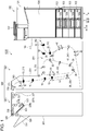
- Fig. 1 is a schematic view illustrating the outline of a printing apparatus according to the embodiment. First, the outline of the printing apparatus 1000 according to the present embodiment will be described with reference to Fig. 1 .
- the printing apparatus 1000 is configured to include a printing unit 100 that ejects ink, which is an example of "liquid”, to print an image on a paper sheet M, which is an example of a "medium”, and a post processing device 500 that is disposed on the downstream side of the printing unit 100 in a transportation direction of the paper sheet M.
- the post processing device 500 includes an intermediate unit 200 and a post processing unit 300.
- the intermediate unit 200 is disposed on the upstream side in the transportation direction of the paper sheet M, dries ink ejected onto the paper sheet M, and feeds the paper sheet M in a state where skew, in which the paper sheet M is transported in a direction oblique with respect to the transportation, is corrected.
- the post processing unit 300 is disposed on the downstream side in the transportation direction of the paper sheet M, stacks the paper sheet M transported from the intermediate unit 200, and performs various post processing such as a stapling process and a punching process with respect to the paper sheet M.
- the printing apparatus 1000 includes the post processing device 500 which is configured of the intermediate unit 200 and the post processing unit 300 and the printing unit 100 which is disposed on the upstream side of the post processing device 500 in the transportation direction of the paper sheet M and ejects ink to print an image on the paper sheet M.
- the printing unit 100 includes a housing 101 that has a rectangular parallelepiped shape, an operation unit 102 which is disposed on the upper portion of the housing 101 in a vertical direction Z, and paper sheet cassettes 103 which are provided in an area from the central portion to the lower portion of the printing unit 100.
- Four paper sheet cassettes 103 are arranged in the vertical direction Z and in each of the paper sheet cassettes 103, the paper sheets M are accommodated being in a stacked state.
- a grip portion 103a which a user can grip is provided on the central portion of each paper sheet cassettes 103 in a transverse direction X.
- a rectangular front plate cover 104 is provided at a position adjacent to the uppermost paper sheet cassette 103.
- the intermediate unit 200 is attached to a left surface of the printing unit 100 in the transverse direction X which is an arrangement direction.
- the intermediate unit 200 includes a housing 291. A portion of the housing 291 on the printing unit 100 side is short in the vertical direction Z and a portion of the housing 291 on the post processing unit 300 side is long in the vertical direction Z.
- the housing 291 is provided with a carry-in port 292 through which the paper sheet M, on which printing has been performed in the printing unit 100, is transported into the housing 291 and a carry-out port 293 through which the paper sheet M is transported to the post processing unit 300.
- the intermediate unit 200 includes a transportation path 201 which is illustrated by a dashed line in Fig. 1 and along which the paper sheet M is transported.
- the transportation path 201 is disposed between the carry-in port 292 and the carry-out port 293.
- a group of pairs of fifth transportation rollers 250, a group of pairs of fourth transportation rollers 240 and a group of pairs of third transportation rollers 230, a group of pairs of second transportation rollers 220, a group of pairs of first transportation rollers 210, a pair of correction rollers 260, and a pair of discharging rollers 270 are sequentially disposed in the transportation direction of the paper sheet M.
- the paper sheet M which is transported into the intermediate unit through the carry-in port 292 is transported in the transportation direction by the group of pairs of fifth transportation rollers 250, the group of pairs of fourth transportation rollers 240 or the group of pairs of third transportation rollers 230, the group of pairs of second transportation rollers 220, the group of pairs of first transportation rollers 210, the pair of correction rollers 260, and the pair of discharging rollers 270 so that the paper sheet M is transported to the post processing unit 300 through the carry-out port 293.
- the group of pairs of first transportation rollers 210 includes a plurality of pairs of first transportation rollers 10 which are disposed on the upstream side of the pair of correction rollers 260 in the transportation direction of the paper sheet M and are driven by the same motor (not shown).
- the group of pairs of second transportation rollers 220 includes a plurality of pairs of second transportation rollers 20 which are disposed on the upstream side of the group of pairs of first transportation rollers 210 in the transportation direction of the paper sheet M and are driven by the same motor (not shown).
- the group of pairs of third transportation rollers 230 includes a plurality of pairs of third transportation rollers 30 which are disposed on the upstream side of the group of pairs of second transportation rollers 220 in the transportation direction of the paper sheet M and are driven by the same motor (not shown).
- the group of pairs of fourth transportation rollers 240 includes a plurality of pairs of fourth transportation rollers 40 which are disposed on the upstream side of the group of pairs of second transportation rollers 220 in the transportation direction of the paper sheet M and are driven by the same motor (not shown).
- the group of pairs of fifth transportation rollers 250 includes a plurality of pairs of fifth transportation rollers 50 which are disposed on the upstream side of the group of pairs of third transportation rollers 230 and the group of pairs of fourth transportation rollers 240 in the transportation direction of the paper sheet M and are driven by the same motor (not shown).
- the pair of correction rollers 260 is disposed on the downstream side of the group of pairs of first transportation rollers 210 in the transportation direction of the paper sheet M while being positioned in the vicinity of the carry-out port 293 and corrects skew of the paper sheet M, in which the paper sheet M is transported in a direction oblique with respect to the transportation direction.
- a distance L2 between the group of pairs of first transportation rollers 210 and the group of pairs of second transportation rollers 220 is greater than a distance L1 between the group of pairs of first transportation rollers 210 and the pair of correction rollers 260.
- the post processing unit 300 is attached to a left surface of the intermediate unit 200 in the transverse direction X which is an arrangement direction and includes a housing 301 that has a rectangular parallelepiped shape. Furthermore, the post processing unit 300 includes a group of pairs of post processing transportation rollers 327, a guiding unit 330, a stacker 328, a pair of discharging rollers 329, and a discharging tray 331, which are sequentially disposed in the transportation direction of the paper sheet M that is illustrated by the dashed line in Fig. 1 .
- the group of pairs of post processing transportation rollers 327 is configured of a pair of first post processing transportation rollers 327A which is disposed close to the carry-out port 293 and a pair of second post processing transportation rollers 327B which is disposed close to the pair of discharging rollers 329. That is, the pair of first post processing transportation rollers 327A and the pair of second post processing transportation rollers 327B are sequentially disposed in a direction from the carry-out port 293 to the pair of discharging rollers 329.
- the pair of first post processing transportation rollers 327A is an example of "a pair of mounting portion side transportation rollers”.
- the paper sheet M transported out of the intermediate unit 200 is transported to the stacker 328 via the pair of discharging rollers 329 and the guiding unit 330.
- the paper sheet M which is processed in a post processing portion 325, is temporarily mounted on the stacker 328 and the stacker 328 is an example of a "mounting portion".
- the stacker 328 is disposed in an oblique direction such that the stacker 328 is inclined downward toward the post processing portion 325. Therefore, one end sides of the paper sheets M mounted on the stacker 328 come into contact with a wall surface 328b of the stacker 328 and one end sides of the paper sheets M are aligned.
- the post processing portion 325 performs various post processing such as the stapling process or the punching process on the paper sheets M. Thereafter, the paper sheets M which have been subject to the post processing are discharged to the discharging tray 331 with the pair of discharging rollers 329 being driven.
- the paper sheets M transported out of the intermediate unit 200 are sequentially transported to the stacker 328 via the pair of discharging rollers 329 and the guiding unit 330 and when a predetermined number of paper sheets M are mounted on the stacker 328, the post processing portion 325 performs the post processing and the paper sheets M are discharged to the discharging tray 331 with the pair of discharging rollers 329 being driven.
- Fig. 2 is a schematic view illustrating the overview of the printing unit.
- a printing portion 110 which performs printing on the paper sheet M while being positioned above the paper sheet M in the vertical direction Z and a transportation unit 130 which transports the paper sheet M along a transportation path 120 are provided.
- the transportation path 120 is formed such that the paper sheet M is transported in a transportation direction which is a direction intersecting a width direction of the paper sheet M, the width direction being a direction parallel to a front-rear direction Y.
- the printing portion 110 includes a line-head type printing head 111, which can eject ink over the entire area in the width direction of the paper sheet M at once, in a lower portion thereof.
- the printing portion 110 prints an image on the paper sheet M by causing ink ejected from the printing head 111 to adhere (land) to a printing surface of the paper sheet M which faces the printing head 111 (surface on which image is printed).
- the transportation unit 130 includes a plurality of pairs of transportation rollers 131, which are arranged along the transportation path 120, and a belt transportation unit 132 which is provided immediately below the printing portion 110. That is, printing is performed with ink being ejected from the printing head 111 to the paper sheet M, which is in a state of being transported by the belt transportation unit 132.
- Ink is aqueous ink in which coloring material is dispersed (or dissolved) in an aqueous medium.
- the coloring material is, for example, a dye and a direct dye, an acidic dye, an edible dye, a basic dye, a reactive dye, a disperse dye, a vat dye, a soluble vat dye, a reactive disperse dye, and the like can be used as the coloring material.
- the coloring material is, for example, a pigment and an azo pigment such as an insoluble azo pigment, a condensed azo pigment, an azo lake, and a chelate azo pigment, a polycyclic pigment such as a phthalocyanine pigment, a perylene pigment, a perinone pigment, an anthraquinone pigment, a quinacridone pigment, a dioxane pigment, a thioindigo pigment, a isoindolinone pigment and a quinophthalone pigment, a dye chelate, a dye lake, a nitro pigment, a nitroso pigment, aniline black, a daylight fluorescent pigment, carbon black, a base metal pigment, and the like can be used as the coloring material.
- an azo pigment such as an insoluble azo pigment, a condensed azo pigment, an azo lake, and a chelate azo pigment
- a polycyclic pigment such as a phthalocyanine pigment, a perylene pigment,
- a solvent is, for example, an aqueous medium and pure water or ultrapure water such as ion exchanged water, ultra-filtered water, reverse osmosis water, distilled water or the like can be used as the solvent.
- water sterilized through ultraviolet irradiation or addition of hydrogen peroxide is used, it is possible to prevent mold and bacteria from being generated in a case where ink is preserved for a long period of time.
- the solvent may contain a volatile water-soluble organic solvent such as ethylene glycol or propylene glycol.
- ink may contain a basic catalyst, a surfactant, tertiary amine, resins, a pH conditioner, a buffer solution, a fixing agent, an antiseptic agent, an antioxidant, an ultraviolet absorber, a chelating agent, an oxygen absorber, and the like in addition to the above-described coloring materials and solvents.
- the belt transportation unit 132 includes a driving roller 133 which is disposed on the upstream side of the printing head 111 in the transportation direction, a driven roller 134 which is disposed on the downstream side of the printing head 111 in the transportation direction, and an endless belt 135 which is suspended between the rollers 133 and 134.
- the driving roller 133 rotates, the belt 135 rotates in a circumferential direction thereof and the paper sheet M is transported to the downstream side with the belt 135 rotating in the circumferential direction. That is, the outer surface of the belt 135 functions as a supporting surface which supports the paper sheet M on which printing is performed.
- the transportation path 120 includes a supply path 140 along which the paper sheet M is transported to the printing portion 110, a discharging path 150 along which the paper sheet M after printing on which printing has been performed by the printing portion 110 is transported, and a branch path 160 which branches off from the discharging path 150.
- the supply path 140 includes a first supply path 141, a second supply path 142, and a third supply path 143.
- the paper sheet M which is inserted through an insertion port 141b which is exposed when a cover 141a provided on a right side surface of the housing 101 is opened, is transported to the printing portion 110. That is, the paper sheet M which is inserted through the insertion port 141b is linearly transported to the printing portion 110 with rotation of a pair of first driving rollers 144.
- the paper sheets M which are accommodated in each of the paper sheet cassettes 103, which are provided in the lower portion of the housing 101 in the vertical direction Z, are transported to the printing portion 110. That is, the uppermost paper sheet M of the paper sheets M, which are accommodated in the paper sheet cassettes 103 in a state of being stacked, is fed by a pickup roller 142a and is transported to the printing portion 110 with rotation of a pair of second driving rollers 146 while being inverted in the vertical direction Z after the paper sheets M are separated from each other by a pair of separating rollers 145 in a one-by-one manner.
- the paper sheet M with one surface on which printing has been performed by the printing portion 110 is transported to the printing portion 110 again. That is, the branch path 160 which branches off from the discharging path 150 is provided on the downstream side of the printing portion 110 in the transportation direction. That is, when duplex printing is performed, the paper sheet M is transported to the branch path 160 with a branch mechanism 147 being operated, the branch mechanism 147 being provided in the middle of the discharging path 150.
- a pair of branch path rollers 161 which can be rotated forwards and backwards is provided on the downstream side of the branch mechanism 147.
- the paper sheet M with one surface on which printing has been performed is once guided to the branch path 160 by the branch mechanism 147 and is transported to the downstream side in the branch path 160 by the pair of branch path rollers 161 rotating forwards. Thereafter, the paper sheet M which has been transported to the branch path 160 is reversely transported from the downstream side to the upstream side in the branch path 160 by the pair of branch path rollers 161 rotating backwards. That is, the transportation direction of the paper sheet M which is transported along the branch path 160 is reversed.
- the paper sheet M which is reversely transported from the branch path 160 is transported to the third supply path 143 and is transported to the printing portion 110 by the plurality of pairs of transportation rollers 131.
- the paper sheet M is transported along the third supply path 143, the paper sheet M is inverted such that a surface thereof on which printing has not been performed faces the printing portion 110 and the paper sheet M is transported to the printing portion 110 with rotation of a pair of third driving rollers 148. That is, the third supply path 143 functions as an inversion transportation path along which the paper sheet M is transported while being inverted in the vertical direction Z.
- the paper sheet M is transported to the printing portion 110 while being curved in the vertical direction Z. Meanwhile, in the first supply path 141, the paper sheet M is transported to the printing portion 110 while being curved more slightly than in the second supply path 142 and the third supply path 143.
- the paper sheet M with one surface or both surfaces on which printing has been performed by the printing portion 110 and the printing is finished is transported by the pairs of transportation rollers 131 along the discharging path 150 which constitutes a downstream side portion of the transportation path 120.
- the discharging path 150 branches into a first discharging path 151, a second discharging path 152, and a third discharging path 153 at a position on the downstream side of a position at which the branch path 160 branches off from the discharging path 150.
- the paper sheet M on which printing is finished is guided by a guiding mechanism (switch guiding unit) 180 to any one of the first to third discharging paths (downstream side discharging path) 151, 152, and 153 which constitute the downstream side portion of the discharging path 150.
- the guiding mechanism 180 is provided at a downstream end of the common discharging path 154.
- the first discharging path (upper discharging path) 151 is provided to extend to an upper portion of the housing 101 and to extend being curved along the branch path 160.
- the paper sheet M which is transported along the first discharging path 151 is discharged via a discharging port 155 which opens at a portion of the housing 101 so as to function as a terminal end of the first discharging path 151.
- the paper sheets M which are discharged through the discharging port 155 fall downward in the vertical direction Z and are discharged to a mounting table 156 in a state of being stacked as illustrated by two-dotted lines in Fig. 2 .
- the paper sheet M is discharged by the plurality of pairs of transportation rollers 131, which are disposed in the discharging path 150, to the mounting table 156 through the discharging port 155 in such a posture that the printing surface at the time of simplex printing faces downward in the vertical direction Z.
- the mounting table 156 has a tip end-rising inclined shape in which the height in the vertical direction Z increases toward the right side in a transverse direction X, and the paper sheets M are mounted on the mounting table 156 in a state of being stacked. At this time, the paper sheets M mounted on the mounting table 156 move to the left side along a slope of the mounting table 156 and are mounted being close to a vertical side wall 157 which is provided below the discharging port 155 of the housing 101.
- the first discharging path 151 includes a discharging inversion path 151a in which the paper sheet M on which printing has been performed by the printing portion 110 is inverted upside down when the paper sheet M is transported to the discharging port 155. That is, in the discharging inversion path 151a, the paper sheet M on which printing has been performed by the printing portion 110 is curved with the printing surface disposed on the inner side and the paper sheet M is inverted so that a state where the printing surface of the paper sheet M faces upward in the vertical direction Z changes to a state where the printing surface faces downward in the vertical direction Z.
- the paper sheet M passes through the discharging inversion path 151a so that the paper sheet M is discharged through the discharging port 155 in a state where the printing surface at the time of simplex printing faces the mounting table 156.
- the second discharging path 152 branches toward a lower position in the vertical direction Z than the first discharging path 151 and extends linearly from the printing portion 110 to a drawer surface portion 106 that forms a portion of the housing 101. Therefore, the paper sheet M which is transported along the second discharging path 152 is not transported being curved as in the case of the first discharging path 151 and is discharged toward a discharging tray 109, which is attached to the drawer surface portion 106, through a discharging port 108, which is formed in the drawer surface portion 106, after being linearly transported in the same posture as when passing through the printing portion 110 with the posture thereof being maintained constant. That is, the second discharging path 152 functions as a non-inversion discharging path along which the paper sheet M is transported to the discharging tray 109 with the paper sheet M being not inverted in the vertical direction.
- the third discharging path 153 (lower discharging path) branches to a lower position in the vertical direction Z than the second discharging path 152 and obliquely extends downward in the vertical direction Z such that the third discharging path 153 extends toward a lower portion of the housing 101.
- the downstream end of the third discharging path 153 is connected to the carry-in port 292 of the intermediate unit 200.
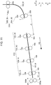
- Fig. 3 is a view corresponding to a schematic view of the intermediate unit illustrated in Fig. 1 and is a schematic view illustrating a state of a transportation system in the intermediate unit.
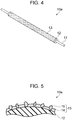
- Fig. 4 is a schematic view illustrating the overview of a driving roller.
- Fig. 5 is a partial enlarged view of the driving roller.
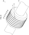
- Fig. 6 is a partial schematic view illustrating the overview of a driven roller.
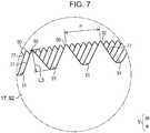
- Fig. 7 is a partial enlarged view illustrating a region VII surrounded by a dashed line in Fig. 6 .
- Fig. 8 is a schematic view illustrating the overview of a pair of correction rollers.
- driving rollers 10a, 20a, 30a, 40a, 50a, 260a, and 270a which are driven by a motor, are illustrated with large circles and driven rollers 10b, 20b, 30b, 40b, 50b, 260b, and 270b, which are rotated in accordance with the rotation of the driving rollers, are illustrated with small circles.
- the transportation path 201 includes a branch point A, a branch point B, and a branch point C at which a transportation path of the paper sheet M branches, a junction point D at which the transportation paths of the paper sheet M join each other, and an end E and an end F which are terminals of the transportation path of the paper sheet M.
- each of the branch point A, the branch point B, and the branch point C is provided with a guide flap (not shown) which distributes the transportation path of the paper sheet M.
- the transportation path 201 is configured of an inlet path 202, a first branch path 203, a first switching back path 204, a first junction path 205, a second branch path 206, a second switching back path 207, a second junction path 208, and an outlet path 209.
- the transportation path 201 between the carry-in port 292 and the branch point A is the inlet path 202.
- the transportation path 201 between the branch point A and the branch point B is the first branch path 203.
- the transportation path 201 between the branch point B and the end E is the first switching back path 204.
- the transportation path 201 between the branch point B and the junction point D is the first junction path 205.
- the transportation path 201 between the branch point A and the branch point C is the second branch path 206.
- the transportation path 201 between the branch point C and the end F is the second switching back path 207.
- the transportation path 201 between the branch point C and the junction point D is the second junction path 208.
- the transportation path 201 between the junction point D and the carry-out port 293 is the outlet path 209.
- the group of pairs of fifth transportation rollers 250 is provided in the inlet path 202, the first branch path 203, and the second branch path 206 and the group of pairs of fifth transportation rollers 250 controls transportation of the paper sheet M.
- the group of pairs of third transportation rollers 230 is provided in the first switching back path 204, and the group of pairs of third transportation rollers 230 controls transportation of the paper sheet M.
- the group of pairs of fourth transportation rollers 240 is provided in the second switching back path 207, and the group of pairs of fourth transportation rollers 240 controls transportation of the paper sheet M.
- the group of pairs of second transportation rollers 220 is provided in the first junction path 205, the second junction path 208, and the upstream side in the outlet path 209 in the transportation direction of the paper sheet M and the group of pairs of second transportation rollers 220 controls transportation of the paper sheet M.
- the group of pairs of first transportation rollers 210, the pair of correction rollers 260, and the pair of discharging rollers 270 are provided on the downstream side in the outlet path 209 in the transportation direction of the paper sheet M and the group of pairs of first transportation rollers 210, the pair of correction rollers 260, and the pair of discharging rollers 270 control transportation of the paper sheet M.
- the different groups of pairs of transportation rollers 210, 220, 230, 240, 250 are separately driven. For example, the groups may be driven by different motors.
- the pair of correction rollers 260 corrects the skew of the paper sheet M.
- the paper sheet M of which the skew is corrected is nipped by the pair of correction rollers 260 and is fed (transported) to the carry-out port 293.
- the pair of correction rollers 260 is positioned on the downstream side of the group of pairs of first transportation rollers 210 in the transportation direction and is disposed such that the leading end T (refer to Fig. 11 ) of the paper sheet M reaches the carry-out port 293 while the paper sheet M is transported by being nipped by the pair of correction rollers 260.
- a state where the pair of correction rollers 260 is disposed such that the leading end T of the paper sheet M reaches the carry-out port 293 while the paper sheet M is transported by being nipped by the pair of correction rollers 260 corresponds to a state where the pair of correction rollers 260 is disposed close to the carry-out port 293.
- the pair of correction rollers 260 is positioned on the downstream side of the group of pairs of first transportation rollers 210 in the transportation direction and is disposed close to the carry-out port 293.
- the pair of correction rollers 260 is disposed such that the leading end T of any type of paper sheet M reaches the carry-out port 293 while the paper sheet M is transported by being nipped by the pair of correction rollers 260 in a case where there are various kinds of paper sheets M which are different in length in the transportation direction. That is, the pair of correction rollers 260 is disposed such that the leading end T of the paper sheet M which is shortest in the transportation direction also reaches the carry-out port 293 while the paper sheet M is transported by being nipped by the pair of correction rollers 260 in a case where there are various kinds of paper sheets M which are different in length in the transportation direction.
- the group of pairs of third transportation rollers 230 and the group of pairs of fourth transportation rollers 240 can be rotated forwards and backwards and can reverse the transportation direction of the paper sheet M in the first switching back path 204 and the second switching back path 207.
- the pair of first transportation rollers 10 disposed in the group of pairs of first transportation rollers 210 is configured of the first driving roller 10a and the first driven roller 10b.
- the pair of second transportation rollers 20 disposed in the group of pairs of second transportation rollers 220 is configured of the second driving roller 20a and the second driven roller 20b.
- the pair of third transportation rollers 30 disposed in the group of pairs of third transportation rollers 230 is configured of the third driving roller 30a and the third driven roller 30b.
- the pair of fourth transportation rollers 40 disposed in the group of pairs of fourth transportation rollers 240 is configured of the fourth driving roller 40a and the fourth driven roller 40b.
- the pair of fifth transportation rollers 50 disposed in the group of pairs of fifth transportation rollers 250 is configured of the fifth driving roller 50a and the fifth driven roller 50b.
- the pair of discharging rollers 270 is configured of the driving roller 270a and the driven roller 270b.
- the first driving roller 10a, the second driving roller 20a, the third driving roller 30a, the fourth driving roller 40a, the fifth driving roller 50a, and the driving roller 270a have the same configuration. Therefore, the description thereof will be made by using the first driving roller 10a as a representative and description of the driving rollers 20a, 30a, 40a, 50a, and 270a will be omitted.
- the first driven roller 10b, the second driven roller 20b, the third driven roller 30b, the fourth driven roller 40b, the fifth driven roller 50b, and the driven roller 270b have the same configuration. Therefore, the description thereof will be made by using the first driven roller 10b as a representative and description of the driven rollers 20b, 30b, 40b, 50b, and 270b will be omitted.
- driving rollers 20a, 30a, 40a, and 50a are collectively referred to as a driving roller 1 and the driven rollers 20b, 30b, 40b, and 50b are collectively referred to as a driven roller 2.
- the first driving roller 10a is rotated and a force (transportation force) transporting the paper sheet M in the transportation direction is applied to the paper sheet M.
- the first driven roller 10b is rotated in accordance with the rotation of the first driving roller 10a with the paper sheet M nipped between the first driving roller 10a and the first driven roller 10b.
- the first driven roller 10b comes into contact with the one surface on which the image is formed and the first driving roller 10a comes into a surface on which no image is formed.
- the first driven roller 10b comes into contact with a surface on which the image is formed later and the first driving roller 10a comes into a surface on which the image is formed earlier.
- one surface of the paper sheet M, on which an image is formed in a case where an image is printed on one surface of the paper sheet M, and a surface, on which an image is formed later in a case where images are printed on both surfaces of the paper sheet M, are referred to as a front surface of the paper sheet M.
- a surface of the paper sheet M, on which no image is formed in a case where an image is formed on one surface of the paper sheet M, and a surface, on which an image is formed earlier in a case where images are printed on both surfaces of the paper sheet M, are referred to as a rear surface of the paper sheet M.
- the first driven roller 10b comes into contact with the front surface of the paper sheet M and the first driving roller 10a comes into contact with the rear surface of the paper sheet M.
- the length of the first driving roller 10a is greater than the maximum assumed width of the paper sheet M and the first driving roller 10a comes into contact with the rear surface of the paper sheet M over the entire region in the width direction of the paper sheet M.
- the first driving roller 10a has a cylindrical shape extending in one direction and includes a driving shaft 11, a rubber roller portion 12 which is inserted on the driving shaft 11, and a rough surface portion 13 that covers the rubber roller portion 12.
- the rough surface portion 13 comes into contact with the rear surface of the paper sheet M.
- the rubber roller portion 12 is fixed to the driving shaft 11 and is provided to be capable of integrally rotating with the driving shaft 11.
- the rough surface portion 13 is configured of a binding agent layer 14 that covers the rubber roller portion 12 and ceramic particles 15 that are embedded such that the ceramic particles 15 protrude from a surface of the binding agent layer 14.
- the ceramic particles 15 are disposed to bite into the rear surface of the paper sheet M with the rough surface portion 13 being provided on the outer circumferential surface of the first driving roller 10a which comes into contact with the paper sheet M, a force in the transportation direction is stably applied to the paper sheet M and the paper sheet M is transported stably. That is, since the ceramic particles 15 bite into the rear surface of the paper sheet M, the first driving roller 10a is not likely to slide on the paper sheet M and a force in the transportation direction from the first driving roller 10a is stably applied to the paper sheet M. Therefore, the paper sheet M is transported stably.
- the contact area between the first driving roller 10a and the paper sheet M is small. Therefore, for example, in a case where duplex printing is performed on the paper sheet M and undried ink remains on the rear surface of the paper sheet M, the undried ink is not likely to be transferred to the first driving roller 10a and the first driving roller 10a is not likely to be contaminated.
- the first driven roller 10b is divided into a plurality of roller bodies (roller portion 17). Therefore, the area of a portion of the first driven roller 10b which comes into contact with the paper sheet M is smaller than the area of a portion of the first driving roller 10a which comes into contact with the paper sheet M.
- the first driven roller 10b is configured to include a driven shaft 16 and the roller portion 17 that is inserted onto the driven shaft 16.
- the first driven roller 10b is configured to include the driven shaft 16 and the plurality of roller portions 17 that are inserted onto the driven shaft 16. Only one roller portion 17 is shown in Fig. 6 .
- Each roller portion 17 is fixed to the driven shaft 16 and is provided to be capable or integrally rotating with the driven shaft 16.
- Each roller portion 17 includes six toothed plates 82.
- Fig. 7 is a partial enlarged view illustrating the region VII as seen from a direction (direction Y) along the driven shaft 16 and illustrates teeth 77 provided on a circumferential surface of the roller portion 17 (six toothed plates 82).
- the teeth 77 are provided on the circumferential surface of the roller portion 17 (six toothed plates 82) such that the positions of the teeth 77 are misaligned and the teeth 77 do not completely overlap each other when seen in the direction Y. That is, the teeth 77 are disposed on the circumferential surface of the roller portion 17 such that all of the teeth 77 can be visually recognized when seen in the direction Y.
- the teeth 77 are disposed such that the sizes of gaps between a tooth 77 and a tooth 77 in the circumferential direction of the roller portion 17 become equal when seen in the direction Y. That is, the teeth 77 of five toothed plates 82 are disposed so that a pitch P between adjacent teeth 77 of one toothed plate 82 is divided into six equal parts. Note that, in the present embodiment, the length of the pitch P between a tooth 77 and a tooth 77 is approximately 0.6 mm.
- the tip ends of the teeth 77 provided on the circumferential surfaces of the six toothed plates 82 come into point contact with the paper sheet M. That is, the first driven roller 10b (roller portion 17) includes the teeth 77 protruding outward from the surface thereof and the teeth 77 come into point contact with the front surface of the paper sheet M.
- each of the teeth 77 provided on the first driven roller 10b is an example of "a convex portion that can come into point contact". That is, the first driven roller 10b includes a surface, on which the convex portions (teeth 77) that can come into point contact with the paper sheet M are provided, and comes into contact with the front surface of the paper sheet M.
- each of the tip ends of the teeth 77 of the toothed plates 82 is called a mountain portion 90
- a groove-shaped valley portion 91 is provided between adjacent mountain portions 90.
- a distance L3 between the bottom of valley portion 91 of the tooth 77 and the top of the mountain portion 90 in the radial direction of the roller portion 17 is approximately 0. 41 mm.
- the shape of the tooth 77 which comes into point contact with the paper sheet M is preferably a triangular shape of which the point angle is equal to or greater than 45 degrees.
- the tooth 77 is configured such that an angle thereof at the mountain portion 90 is 60 degrees.
- each tooth 77 has a shape protruding outward from the surface of the first driven roller 10b and the contact area with respect to the paper sheet M can be smaller than that of the ceramic particles 15.
- undried ink is more likely to remain on the front surface of the paper sheet M than on the rear surface of the paper sheet M.
- the contact area with respect to the paper sheet M of the first driven roller 10b is smaller than that of the first driving roller 10a, the undried ink is not likely to be transferred to the first driven roller 10b and the first driven roller 10b is not likely to be contaminated.
- the first driven roller 10b is not likely to slide on the paper sheet M and can be stably rotated in accordance with rotation of the first driving roller 10a with the paper sheet M nipped between the first driving roller 10a and the first driven roller 10b.
- the pair of correction rollers 260 is configured of the driving roller 260a and the driven roller 260b.
- the driving roller 260a is rotated.
- the driven roller 260b is rotated in accordance with the rotation of the driving roller 260a with the paper sheet M nipped between the driving roller 260a and the driven roller 260b. That is, the pair of correction rollers 260 includes the driving roller 260a which is rotated in a direction in which the paper sheet M is transported toward the carry-out port 293 and the driven roller 260b which is rotated in accordance with the rotation of the driving roller 260a with the paper sheet M nipped between the driving roller 260a and the driven roller 260b.
- the driving roller 260a is an example of a "first roller” and the driven roller 260b is an example of a "second roller”.
- the driving roller 260a comes into contact with the front surface of the paper sheet M and the driven roller 260b comes into contact with the rear surface of the paper sheet M. That is, the driven rollers 20b, 30b, 40b, 50b, and 270b and the driving roller 260a come into contact with the front surface of the paper sheet M and the driving rollers 20a, 30a, 40a, 50a, and 270a and the driven roller 260b come into contact with the rear surface of the paper sheet M.
- a configuration in which the driven roller 260b comes into contact with the front surface of the paper sheet M and the driving roller 260a comes into contact with the rear surface of the paper sheet M may also be adopted. That is, a configuration in which the driven rollers 20b, 30b, 40b, 50b, and 270b and the driven roller 260b come into contact with the front surface of the paper sheet M and the driving rollers 20a, 30a, 40a, 50a, and 270a and the driving roller 260a come into contact with the rear surface of the paper sheet M may also be adopted.
- the driving roller 260a is configured to include a driving shaft 264 and a plurality of rollers 265 which are inserted onto the driving shaft 264.
- Each roller 265 is fixed to the driving shaft 264 and is provided to be capable or integrally rotating with the driving shaft 264.
- the roller 265 has the same configuration as the roller portion 17 (refer to Fig. 6 ) of the first driven roller 10b in the pair of first transportation rollers 10. That is, a surface of the roller 265 is provided with teeth 77 (refer to Fig. 7 ) protruding outward from the surface and the teeth 77 come into point contact with the front surface of the paper sheet M.
- the driving roller 260a includes the surface on which the teeth 77 that can come into point contact with the paper sheet M are provided.
- the teeth 77 are provided on the circumferential surface of the driving roller 260a (roller portion 17) such that the positions of the teeth 77 are misaligned and the teeth 77 do not completely overlap each other when seen in the direction Y (refer to Fig. 7 ).
- each of the teeth 77 provided on the driving roller 260a is an example of "a convex portion that can come into point contact". That is, the driving roller 260a includes a surface, on which the convex portions (teeth 77) that can come into point contact with the paper sheet M are provided.
- the driving roller 260a since the teeth 77 provided on the surface of the driving roller 260a bite into the front surface of the paper sheet M, the driving roller 260a is not likely to slide on the paper sheet M and a force in the transportation direction can be stably applied to the paper sheet M. Therefore, the paper sheet M can be transported stably. Since the driving roller 260a is provided with the teeth 77 on the surface thereof, the driving roller 260a is not likely to be contaminated.
- the driven roller 260b is configured to include a shaft 266 and a plurality of rollers 267 which are inserted onto the driven shaft 266.
- Each roller 267 is rotatably supported by the shaft 266 and is disposed so as to face each roller 265 of the driving roller 260a.
- the roller 267 may rotate on a stationary shaft 266, or it may be fixed to a rotatable shaft 266.
- Each of the plurality of rollers 267 includes a flat circumferential surface with no uneven portion. Accordingly, the paper sheet M is likely to slide on the driven roller 260b in comparison with the driving roller 260a that includes the teeth 77 on the surface thereof.
- the driven roller 260b includes a flat surface on which the paper sheet M is likely to slide.
- the driven roller 260b is configured with a material which is excellent in wear resistance and has a high slidability.
- the driven roller 260b is configured with polyacetal (acetal resin) and has a self-lubricating property and a high slidability in addition to the wear resistance.
- polyacetal acetal resin
- polyamide, polytetrafluoroethylene (fluororesin), polyphenylene sulfide, and the like can be used as the constituent material of the driven roller 260b.
- the driven roller 260b comes into surface contact with the rear surface of the paper sheet M.
- the paper sheet M transported into the intermediate unit 200 reaches the pair of correction rollers 260 via the group of pairs of fifth transportation rollers 250, the group of pairs of fourth transportation rollers 240, the group of pairs of third transportation rollers 230, the group of pairs of second transportation rollers 220, and the group of pairs of first transportation rollers 210. While the paper sheet M is transported via the group of pairs of fifth transportation rollers 250, the group of pairs of fourth transportation rollers 240, the group of pairs of third transportation rollers 230, the group of pairs of second transportation rollers 220, and the group of pairs of first transportation rollers 210, ink adhering to the rear surface of the paper sheet M is gradually dried.
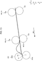
- Fig. 9 is a schematic view illustrating a transportation path of the paper sheet.
- Fig. 10 is a schematic view illustrating a transportation path of another paper sheet.
- Figs. 9 and 10 are views corresponding to Fig. 3 and components such as the driving rollers 20a, 30a, 40a, 50a, 260a, and 270a and the driven rollers 20b, 30b, 40b, 50b, 260b, and 270b which are not necessary for describing the transportation path are not illustrated. Furthermore, in Figs. 9 and 10 , a portion of the transportation path 201 which is used for transportation of the paper sheet M is illustrated with a solid line and a portion of the transportation path 201 which is not used for the transportation of the paper sheet M is illustrated with a broken line.
- each of arrows in Figs. 9 and 10 denotes the transportation direction of the paper sheet M and the arrows are given reference symbols H1 to H6.
- a first transportation path 201a along which the paper sheet M is transported is configured of the inlet path 202, the first branch path 203, the first switching back path 204, the first junction path 205, and the outlet path 209.
- the paper sheet M which is transported into the intermediate unit through the carry-in port 292, passes through the inlet path 202, advances in a transportation direction H1 in the first branch path 203, and is transported into the first switching back path 204.
- the paper sheet M which is transported into the first switching back path 204 advances in a transportation direction H2. Thereafter, the advancing direction of the paper sheet M is reversed (switched back) and thus the paper sheet M advances in a transportation direction H3 which is opposite to the transportation direction H2 and is transported into the first junction path 205.
- the paper sheet M advances in a transportation direction H4 in the first junction path 205, is transported into the outlet path 209, advances in a transportation direction H5 and a transportation direction H6 in the outlet path 209, and is transported to the post processing unit 300 through the carry-out port 293.
- another transportation path 201b (second transportation path 201b) along which the paper sheet M is transported is configured of the inlet path 202, the second branch path 206, the second switching back path 207, the second junction path 208, and the outlet path 209.
- the paper sheet M which is transported into the intermediate unit through the carry-in port 292, passes through the inlet path 202, advances in a transportation direction H1 in the second branch path 206, and is transported into the second switching back path 207.
- the paper sheet M which is transported into the second switching back path 207 advances in a transportation direction H2. Thereafter, the advancing direction of the paper sheet M is reversed (switched back) and thus the paper sheet M advances in a transportation direction H3 which is opposite to the transportation direction H2 and is transported into the second junction path 208.
- the paper sheet M advances in a transportation direction H4 in the second junction path 208, is transported into the outlet path 209, advances in the transportation direction H5 and the transportation direction H6 in the outlet path 209, and is transported to the post processing unit 300 through the carry-out port 293.
- the paper sheet M which is transported into the intermediate unit through the carry-in port 292 is guided toward the first transportation path 201a by a guide flap provided at the branch point A. Thereafter, the next paper sheet M which is transported into the intermediate unit through the carry-in port 292 is guided toward the second transportation path 201b by the guide flap provided at the branch point A.
- transportation of the paper sheet M along the first transportation path 201a and transportation of the paper sheet M along the second transportation path 201b are alternately repeated.
- the intermediate unit 200 includes the two transportation paths (first transportation path 201a and second transportation path 201b), the transportation ability for the paper sheet M can be improved in comparison with a case where the intermediate unit 200 includes one transportation path.
- the transportation paths 201a and 201b include the switching back paths 204 and 207, the transportation paths 201a and 201b can be lengthened in comparison with a case where the transportation paths 201a and 201b do not include the switching back paths 204 and 207. That is, the intermediate unit 200 according to the present embodiment is configured such that it is possible to achieve space saving, improve the transportation ability for the paper sheet M, and lengthen the transportation paths 201a and 201b.
- ink aqueous ink
- ink aqueous ink
- the intermediate unit 200 the moisture absorbed by the paper sheet M is evaporated with the paper sheet M being transported along the transportation paths 201a and 201b so that ink adhering to the paper sheet M is dried. Since the transportation paths 201a and 201b are long, it is possible to more appropriately dry the ink adhering to the paper sheet M than in a case where the transportation paths 201a and 201b are short.
- the transportation paths 201a and 201b function as drying paths in which the moisture absorbed by the paper sheet M is dried so that the ink adhering to the paper sheet M is appropriately dried.
- the position of the front surface of the paper sheet M with respect to the transportation direction is also reversed. That is, after the advancing direction of the paper sheet M is switched back in the switching back paths 204 and 207, the position of the front surface of the paper sheet M with respect to the transportation direction is reversed.
- the position of the front surface of the paper sheet M, which is transported into the intermediate unit through the carry-in port 292, with respect to the transportation direction is reversed in the switching back paths 204 and 207.
- the paper sheet M is transported to the post processing unit 300 through the carry-out port 293 in a state of the position of the front surface with respect to the transportation direction is reversed.
- the paper sheet M is transported into the intermediate unit through the carry-in port 292 in a state where the front surface is disposed on the upper side in the vertical direction Z and the paper sheet M is transported out of the intermediate unit through the carry-out port 293 in a state where the front surface is disposed on the lower side in the vertical direction Z. That is, in the printing apparatus 1000, the paper sheet M is transported into the intermediate unit 200 from the printing unit 100 in a state where the front surface is disposed on the upper side in the vertical direction Z and the paper sheet M is transported into the post processing unit 300 from the intermediate unit 200 in a state where the front surface is disposed on the lower side in the vertical direction Z.
- the paper sheet M swells. Furthermore, the printing duty of the paper sheet M is not uniform and the paper sheet M includes a portion with a high printing duty on which a dense image is formed (a portion onto which a large amount of ink is ejected) and a portion with a low printing duty on which a light image is formed (a portion onto which a small amount of ink is ejected). At the portion with the high printing duty, since the paper sheet M absorbs a large amount of moisture, the paper sheet M significantly swells. At the portion with the low printing duty, since the paper sheet M absorbs a small amount of moisture, the paper sheet M slightly swells.
- the paper sheet M which has absorbed moisture and has curled is transported along the transportation paths 201a and 201b. Furthermore, the curling state of the paper sheet M is changed depending on an image pattern to be printed or an ink composition (moisture content) and thus the paper sheet M which has curled in various ways is transported along the transportation paths 201a and 201b.
- leading end T an end portion of the paper sheet M which is disposed on the downstream side in the transportation direction (hereinafter, referred to as leading end T (refer to Fig. 11 )) is likely to come into contact with the driving roller 1 or the driven roller 2 in a uniform manner and thus the skew of the paper sheet M with respect to the transportation direction is not likely to occur.
- the paper sheet M curls, it is difficult for the leading end T of the paper sheet M to come into contact with the driving roller 1 or the driven roller 2 in a uniform manner and the skew of the paper sheet M with respect to the transportation direction is likely to occur. Furthermore, the state of the skew of the paper sheet M changes depending on the state of curling of the paper sheet M and thus the skew of the paper sheet M may be slight or the skew of the paper sheet M may be significant.
- the paper sheet M of which the skew with respect to the transportation direction is slight or the paper sheet M of which the skew with respect to the transportation direction is significant is transported into the post processing unit 300 from the intermediate unit 200.
- the paper sheet M is mounted on the stacker 328 in a state of being skew and thus it is difficult for the post processing portion 325 to appropriately perform the post processing on the paper sheet M mounted on the stacker 328.
- the intermediate unit 200 includes a mechanism for correcting the skew of the paper sheet M with respect to the transportation direction in the vicinity of the carry-out port 293 through which the paper sheet M is transported to the post processing unit 300.
- the skew of the paper sheet M with respect to the transportation direction which occurs when the paper sheet M is transported along the transportation paths 201a and 201b, is appropriately corrected in the vicinity of the carry-out port 293. Therefore, the paper sheets M are mounted on the stacker 328 in a state of being aligned and thus it is possible for the post processing portion 325 to appropriately perform the post processing on the paper sheets M mounted on the stacker 328.
- Fig. 11 is an enlarged view illustrating a portion of Fig. 3 in which the pair of correction rollers is disposed and is a schematic view illustrating a state before the skew of the paper sheet is corrected. That is, Fig. 11 illustrates a state where a paper sheet M1 is transported to a position immediately before the pair of correction rollers 260 by the group of pairs of first transportation rollers 210.
- Fig. 12 is a process flowchart illustrating a method of correcting the skew of the paper sheet.
- Fig. 13 is a partial enlarged view of Fig. 11 and is a schematic view illustrating the state of a process illustrated in Fig. 12 .
- Figs. 14 and 15 are views corresponding to Fig. 13 and are schematic views illustrating the state of the process illustrated in Fig. 12 .
- a pair of first transportation rollers 10A, a pair of first transportation rollers 10B, a pair of first transportation rollers 10C, a pair of first transportation rollers 10D, a pair of second transportation rollers 20A, and a pair of second transportation rollers 20B are sequentially disposed.
- the group of pairs of first transportation rollers 210 is configured of the pair of first transportation rollers 10A, the pair of first transportation rollers 10B, the pair of first transportation rollers 10C, and the pair of first transportation rollers 10D and a portion of the group of pairs of second transportation rollers 220 is configured of the pair of second transportation rollers 20A and the pair of second transportation rollers 20B.
- the paper sheet M1 is transported in the transportation direction H6 by the group of pairs of first transportation rollers 210 and the leading end T of the paper sheet M1 is disposed immediately before the pair of correction rollers 260. Since the paper sheet M1 is transported in a direction oblique with respect to the transportation direction H6, the leading end T of the paper sheet M1 intersects a direction orthogonal to the transportation direction H6.
- the leading end T of the paper sheet M1 is orthogonal to the transportation direction H6.
- the leading end T of the paper sheet M1 intersects a direction orthogonal (that is, is not orthogonal) to the transportation direction H6.
- next paper sheet M2 is transported in the transportation direction H6 by the group of pairs of second transportation rollers 220.
- the leading end T of the next paper sheet M2 is disposed so as to protrude from the pair of second transportation rollers 20A to the group of pairs of first transportation rollers 210 side.
- a method of correcting the skew of the paper sheet M includes a process (Step S1) of guiding the leading end T of the paper sheet M to a nip position P1 of the pair of correction rollers 260, a process (Step S2) of correcting the skew of the paper sheet M at the nip position P1, and a process (Step S3) of transporting the paper sheet M of which the skew has been corrected toward the carry-out port 293.
- Step S1 the pair of correction rollers 260 (driving roller 260a) is stopped, the group of pairs of first transportation rollers 210 (first driving roller 10a) is driven, and a force in the transportation direction H6 from the group of pairs of first transportation rollers 210 is applied to the paper sheet M1.
- the paper sheet M is transported in the transportation direction H6 by the group of pairs of first transportation rollers 210 and the leading end T of the paper sheet M1 comes into contact with a position P2 of the driven roller 260b of the pair of correction rollers 260 for the first time. Since the driven roller 260b is configured with a material with a high slidability, the leading end T of the paper sheet M1 slides on the flat surface of the driven roller 260b due to the force in the transportation direction H6 and is guided to the nip position P1 of the pair of correction rollers 260.
- the driven roller 260b includes a flat surface and in a case where the skew of the paper sheet M is corrected, the driven roller 260b causes the leading end T of the paper sheet M (end of paper sheet M) to slide thereon so that the paper sheet M is guided to the nip position P1 at which the paper sheet M is nipped between the driving roller 260a and the driven roller 260b.
- Step S2 when the leading end T of the paper sheet M is guided to the nip position P1 of the pair of correction rollers 260, connection between the first driving roller 10a and the motor is released in the order of the pair of first transportation rollers 10D, the pair of first transportation rollers 10C, the pair of first transportation rollers 10B, and the pair of first transportation rollers 10A so that the first driving roller 10a transitions into an idle state and the forces in the transportation direction H6 being applied to the paper sheet M from the pairs of first transportation rollers 10A, 10B, 10C, and 10D are sequentially released.
- the pair of first transportation rollers 10A is an example of a "downstream side pair of first transportation rollers" and the pair of first transportation rollers 10B is an example of an "upstream side pair of first transportation rollers”.
- the pair of first transportation rollers 10B and the pair of first transportation rollers 10C is an example of the "downstream side pair of first transportation rollers” and the pair of first transportation rollers 10C is an example of the "upstream side pair of first transportation rollers”.
- the pair of first transportation rollers 10C is an example of the "downstream side pair of first transportation rollers" and the pair of first transportation rollers 10D is an example of the "upstream side pair of first transportation rollers”.
- the leading end T of the paper sheet M1 is disposed in a direction along the nip position P1 of the pair of correction rollers 260, that is, in a direction orthogonal to the transportation direction H6.
- Step S2 a state where the leading end T of the paper sheet M1 intersects a direction orthogonal to the transportation direction H6 (state where there is skew of paper sheet M) is corrected to a state where the leading end T of the paper sheet M1 is orthogonal to the transportation direction H6 (state where skew of paper sheet M has been corrected).
- the teeth 77 are provided on the circumferential surface of the driving roller 260a such that the positions of the teeth 77 are misaligned and the teeth 77 do not completely overlap each other when seen in the direction Y (refer to Fig. 7 ).
- the teeth 77 are provided on the circumferential surface of the driving roller 260a such that the teeth 77 overlap each other when seen in the direction Y, the leading end T of the paper sheet M which comes into contact with the pair of correction rollers 260 intrudes into an area between the tooth 77 and the tooth 77 of the driving roller 260a and thus the leading end T is not guided to the nip position P1 of the pair of correction rollers 260. Therefore, it may not be possible to appropriately correct the skew of the paper sheet M.
- the teeth 77 are provided such that the teeth 77 do not completely overlap each other, the leading end T of the paper sheet M is not likely to intrude into an area between adjacent teeth 77 of the driving roller 260a and thus the leading end T is stably guided to the nip position P1 of the pair of correction rollers 260. Therefore, it is possible to appropriately correct the skew of the paper sheet M.
- the forces in the transportation direction H6 applied to the paper sheet M1 from the pairs of first transportation rollers 10 be released sequentially in such a manner that the more distant the pair of first transportation rollers 10 is from the pair of correction rollers 260, the earlier the force is released. That is, in a case of correcting the skew of the paper sheet M, it is preferable that the force in the transportation direction H6 applied to the paper sheet M from the "upstream side pair of first transportation rollers" be released earlier and the force in the transportation direction H6 applied to the paper sheet M from the "downstream side pair of first transportation rollers" be released later.
- Step S3 the pair of correction rollers 260 is rotated with the driving roller 260a being driven so that the paper sheet M of which the skew has been corrected is transported toward the carry-out port 293.
- Step S1 and Step S2 are executed with respect to the next paper sheet M2 so as to correct the skew of the next paper sheet M2.
- Step S2 the group of pairs of second transportation rollers 220 continues to be driven. That is, even while transportation of the paper sheet M1 in the transportation direction H6 is inhibited by the pair of correction rollers 260, the next paper sheet M2 is transported in the transportation direction H6 by the group of pairs of second transportation rollers 220.
- the distance L2 between the group of pairs of first transportation rollers 210 and the group of pairs of second transportation rollers 220 is greater than the distance L1 between the group of pairs of first transportation rollers 210 and the pair of correction rollers 260 and the distance L2 is set such that the next paper sheet M2 does not interfere with the paper sheet M1 in a case where the next paper sheet M2 is transported in the transportation direction H6 while the transportation of the paper sheet M1 in the transportation direction H6 is inhibited.
- Step S2 in a case where the transportation of the paper sheet M1 in the transportation direction H6 is inhibited by the pair of correction rollers 260 and the next paper sheet M2 is transported in the transportation direction H6 by the group of pairs of second transportation rollers 220, the next paper sheet M2 does not interfere with the paper sheet M1 and preferably does not come close to the paper sheet M1.
- Step S2 it is not necessary to stop the transportation of the paper sheet M performed by the group of pairs of second transportation rollers 220 in Step S2 and thus it is possible to improve the transportation ability for the paper sheet M in the transportation path 201 in comparison with a case where the transportation of the paper sheet M performed by the group of pairs of second transportation rollers 220 is stopped.
- the distance L2 between the group of pairs of first transportation rollers 210 and the group of pairs of second transportation rollers 220 be greater than the distance L1 between the pair of correction rollers 260 and the group of pairs of first transportation rollers 210.
- the pair of correction rollers 260 is disposed close to the carry-out port 293 so that the leading end T of the paper sheet M reaches the carry-out port 293 while the paper sheet M is transported by being nipped by the pair of correction rollers 260.
- the skew of the paper sheet M which occurs when the paper sheet M is transported along the transportation paths 201a and 201b, is corrected by the pair of correction rollers 260 in the vicinity of the carry-out port 293. Therefore, the paper sheets M of which the skew has been corrected are transported into the post processing unit 300 through the carry-out port 293 and the paper sheets M are mounted on the stacker 328 in the post processing unit 300 in a state of being aligned. Therefore, it is possible for the post processing portion 325 to appropriately perform the post processing on the paper sheets M mounted on the stacker 328.
- the pair of correction rollers 260 is disposed such that the leading end T of the paper sheet M reaches the pair of first post processing transportation rollers 327A while the paper sheet M is transported by being nipped by the pair of correction rollers 260.
- the pair of correction rollers 260 is disposed at such a distance that both of the pair of correction rollers 260 and the pair of first post processing transportation rollers 327A can nip the paper sheet M in a case where the paper sheet M of which the skew has been corrected by the pair of correction rollers 260 is transported toward the stacker 328 (post processing portion 325).
- the pair of correction rollers 260 is disposed at a such distance that both of the pair of correction rollers 260 and the pair of first post processing transportation rollers 327A also can nip the paper sheet M which is shortest in the transportation direction in a case where there are various kinds of paper sheets M which are different in length in the transportation direction.
- the pair of correction rollers 260 is disposed at a such distance that both of the pair of correction rollers 260 and the pair of first post processing transportation rollers 327A can nip the paper sheet M even in a case where the size of the paper sheet M is A4 and the paper sheet M is transported in a state where the long sides of the paper sheet M are disposed in a direction intersecting the transportation direction from the pair of correction rollers 260 to the pair of first post processing transportation rollers 327A and the short sides of the paper sheet M are disposed in a direction parallel to the transportation direction from the pair of correction rollers 260 to the pair of first post processing transportation rollers 327A (case where A4-sized paper sheet M is subject to transverse transportation). That is, the distance between the pair of correction rollers 260 and the pair of first post processing transportation rollers 327A is smaller than the length of the short sides of the A4-sized paper sheet M.
- the paper sheet M of which the skew has been corrected by the pair of correction rollers 260 is nipped by both of the pair of correction rollers 260 on the intermediate unit 200 side and the pair of first post processing transportation rollers 327A on the post processing unit 300 side and the paper sheet M is transported to the stacker 328 on the post processing unit 300 side in a state where the skew thereof has been corrected reliably.
- the paper sheet M of which the skew has been corrected is reliably transported into the stacker 328 on the post processing unit 300 side and it is possible for the post processing portion 325 on the post processing unit 300 side to reliably perform the appropriate post processing on the paper sheet M mounted on the stacker 328.
- the intermediate unit 200 includes the switching back paths 204 and 207.
- the invention is not limited to this.
- the intermediate unit 200 may not include the switching back paths 204 and 207.
- a configuration in which the switching back paths 204 and 207 are provided in the printing unit 100 may be adopted instead of a configuration in which the switching back paths 204 and 207 are provided in the intermediate unit 200.
- the intermediate unit 200 may include the carry-in port 292 through which the paper sheet M is transported into the intermediate unit from the printing unit 100 that ejects ink on the paper sheet M to print an image on the paper sheet M, the carry-out port 293 through which the paper sheet M is transported to the post processing unit 300 that performs post processing on the paper sheet M, and a transportation path that is disposed between the carry-in port 292 and the carry-out port 293 and is provided with a drying path in which ink is dried.
- the post processing device 500 is configured of the intermediate unit 200 and the post processing unit 300 and the intermediate unit 200 includes the carry-out port 293 through which the paper sheet M is transported to the post processing unit 300.
- the invention is not limited to this.
- the post processing device 500 may have a configuration in which the carry-out port 293 is not provided and the intermediate unit 200 and the post processing unit 300 are integrally formed with each other, for example, a configuration in which the groups of pairs of transportation rollers 210, 220, 230, 240, and 250 and the pair of correction rollers 260, which constitute the transportation path 201, the stacker 328, and the post processing portion 325 are disposed in the same housing.
- the printing apparatus 1000 is configured of the printing unit 100, the intermediate unit 200, and the post processing unit 300 and the intermediate unit 200 includes the carry-in port 292 through which the paper sheet M is transported into the intermediate unit from the printing unit 100 and the carry-out port 293 through which the paper sheet M is transported to the post processing unit 300.
- the invention is not limited to this.
- the printing apparatus 1000 may have a configuration in which the carry-in port 292 and the carry-out port 293 are not provided and the printing unit 100, the intermediate unit 200, and the post processing unit 300 are integrally formed with each other, for example, a configuration in which the printing portion 110 that ejects ink to print an image on the paper sheet M, the groups of pairs of transportation rollers 210, 220, 230, 240, and 250, the pair of correction rollers 260, the stacker 328, and the post processing portion 325 are disposed in the same housing.
- the roller 265 of the driving roller 260a has the same configuration as the roller portion 17 (refer to Fig. 6 ) of the first driven roller 10b.
- the roller 265 may have the same configuration as the rubber roller portion 12 of the first driving roller 10a. That is, the driving roller 260a may include a rough surface with the ceramic particles 15 provided thereon.
- the driving roller 260a includes a rough surface with the ceramic particles 15 provided thereon, it is possible to achieve the same effect as the above-described embodiment that the paper sheet M is stably transported and undried ink is not likely to be transferred.
- Ink which adheres to the rear surface of the paper sheet M as a result of duplex printing on the paper sheet M is dried at a position on the downstream side in the transportation direction in the transportation path 201. Accordingly, undried ink is not likely to remain on the rear surface side of the paper sheet M. Therefore, at a position on the downstream side in the transportation direction in the transportation path 201, even if the driving roller 1 comes into surface contact with the rear surface of the paper sheet M, the driving roller 1 is not likely to be contaminated with undried ink.
- the driving roller 1 can come into surface contact with the rear surface of the paper sheet M at a position on the downstream side in the transportation direction in the transportation path 201 . That is, the driving roller 1 may be configured of the driving shaft 11 and the rubber roller portion 12 inserted onto the driving shaft 11 and the rough surface portion 13 covering the rubber roller portion 12 may be omitted.
- each of the first driving roller 10a and the second driving roller 20a may be configured of the driving shaft 11 and the rubber roller portion 12 inserted onto the driving shaft 11 and the rough surface portion 13 covering the rubber roller portion 12 may be omitted.
- first driving roller 10a of each of the pairs of first transportation rollers 10A and 10B in the group of pairs of first transportation rollers 210 may be configured of the driving shaft 11 and the rubber roller portion 12 inserted onto the driving shaft 11 and the first driving roller 10a of each of the pairs of first transportation rollers 10C and 10D in the group of pairs of first transportation rollers 210 may be configured of the driving shaft 11, the rubber roller portion 12 inserted onto the driving shaft 11, and the rough surface portion 13.
- the printing head 111 which the printing portion 110 includes is not limited to a line-head type printing head and the printing head 111 may be a serial head type printing head which can move along the width direction intersecting the transportation direction of the paper sheet M.
- the printing apparatus may be a fluid ejecting apparatus which ejects or discharges fluid other than ink (liquid substance which is obtained by dispersing or mixing functional material particles into liquid or gel-like fluid substance) to perform printing.
- the printing apparatus may be a liquid substance ejecting apparatus which ejects a liquid substance, in which materials such as electrode materials and coloring materials (pixel material) used for manufacturing a liquid crystal display, an electroluminescence (EL) display, and a planar light emission display are included while being dispersed or dissolved therein.
- the printing apparatus may be a fluid substance ejecting apparatus which ejects a fluid substance such as gel (for example, physical gel).
- fluid does not include fluid consisting only of gas and examples of fluid include liquid (including inorganic solvent, organic solvent, solution, liquid resin, liquid metal (metallic melt), or like), a liquid substance, and a fluid substance.
Landscapes
- Engineering & Computer Science (AREA)
- Mechanical Engineering (AREA)
- Physics & Mathematics (AREA)
- General Physics & Mathematics (AREA)
- Registering Or Overturning Sheets (AREA)
Description
- The present invention relates to an intermediate unit, a post processing device in which the intermediate unit is installed, and a printing apparatus in which the post processing device is installed.
- In the related art, there is known a printing system (printing apparatus) including a multifunction machine (image forming apparatus) that prints an image on a paper sheet, which is an example of a medium, and a post processing device that performs post processing such as a punching process or a stapling process with respect to the paper sheet on which the image has been printed (refer to
JP-A-2015-107840 - The printing system (printing apparatus) described in
JP-A-2015-107840 - Meanwhile, in the image forming apparatus and the intermediate unit, skew, in which a paper sheet is transported in a direction oblique with respect to a transportation direction of the paper sheet, is likely to occur due to various reasons such as eccentricity of a rotation axis of a roller transporting the paper sheet or curling of the paper sheet. In the printing apparatus described in
JP-A-2015-107840 -
US 6 460 687 discloses a photofinisher unit located between a laminator and an embosser. The laminator laminates printed sheets which have been pre-printed by an inkjet printer. The photofinisher acts as a buffer to account for the differing feeding speeds of the laminator and embosser. Deskewing rollers are provided in a feeding path through the photofinisher unit, downstream of a transport roller group.
US 2011/140343 discloses a medium conveying device which includes a first guide member, a second guide member, a conveying member, and a support member.
US 6 308 026 discloses an image forming apparatus comprising an image output module, a sheet supply module, and a sheet discharge module.
US2010/002037 discloses a printer comprising: an image former that forms a plurality of images on a plurality of sheets; a circulation transfer route composed of a first transfer route that transfers each sheet fed from a feeding route toward a discharging route, and a second transfer route that is branched from the first transfer route and returns each sheet received from the first transfer route to the first transfer route.
US 2015/116411 discloses a printing paper sheet conveyance unit that conveys a printing paper sheet in a given conveyance direction. - The invention can be realized in the following aspects or application examples.
- According to this application example, there is provided an intermediate unit according to
claim 1. - For example, if the liquid is aqueous ink and an image is formed on the medium by means of the aqueous ink, the medium absorbs moisture of the aqueous ink and the medium swells. Furthermore, the swelling state of the medium is different between a portion on which a large amount of aqueous ink is ejected and a dense image is formed and a portion on which a small amount of aqueous ink is ejected and a light image is formed and thus the medium is likely to curl (be curved) due to the partial difference in swelling state.
- Furthermore, the curling state of the medium depends on difference in swelling state and thus the medium which has curled in various ways is transported into the intermediate unit from the printing unit and is transported along the transportation path in the intermediate unit.
- If the curled medium is transported to the transportation path in the intermediate unit, it is difficult for the pair of transportation rollers to uniformly nip the medium and to apply the transportation force in the transportation direction to the medium and thus the skew of the medium with respect to the transportation direction becomes likely to occur. However, since the pair of correction rollers is provided, even in a case where the skew of the medium occurs in the transportation path, the medium can be transported out of the carry-out port with the skew of the medium with respect to the transportation direction being corrected.
- Since the first roller comes into point contact with the medium, the contact area between the first roller and the medium is small in comparison with a case where the first roller comes into surface contact with the medium and dirt on the medium is not likely to be transferred to the first roller. Furthermore, since the first roller is disposed such that the convex portion bites into the medium in a case where the medium is transported by being nipped between the first roller and the second roller and the first roller is not likely to slide on the medium, it is possible to stably transport the medium.
- In the intermediate unit according to the application example, the group of pairs of first transportation rollers is preferably configured of a plurality of pairs of first transportation rollers which are driven by the same motor, the group of pairs of first transportation rollers preferably includes an upstream side pair of first transportation rollers which is disposed on the upstream side of the pair of correction rollers in the transportation direction, and a downstream side pair of first transportation rollers which is disposed on the upstream side of the pair of correction rollers in the transportation direction and is disposed on the downstream side of the upstream side pair of first transportation rollers in the transportation direction, and, in a case where the skew is corrected, a transportation force which is applied to the medium by the downstream side pair of first transportation rollers is preferably released after a transportation force which is applied to the medium by the upstream side pair of first transportation rollers is released.
- If the transportation force in the transportation direction which is applied to the medium by the downstream side pair of first transportation rollers is released earlier and the transportation force in the transportation direction which is applied to the medium by the upstream side pair of first transportation rollers is released later in a case where the skew of the medium is corrected, the medium warps at a position between the downstream side pair of first transportation rollers and the upstream side pair of first transportation rollers and thus transportation failure such as a jam of the medium is likely to occur.
- Therefore, in a case where the skew of the medium is corrected, the transportation force in the transportation direction which is applied to the medium by the upstream side pair of first transportation rollers is released earlier and the transportation force in the transportation direction which is applied to the medium by the downstream side pair of first transportation rollers is released later so that the medium is not likely to warp at a position between the downstream side pair of first transportation rollers and the upstream side pair of first transportation rollers and transportation failure such as a jam of the medium is not likely to occur.
- The intermediate unit according to the application example preferably further includes a group of pairs of second transportation rollers that is disposed on the upstream side of the group of pairs of first transportation rollers in the transportation direction and in which a plurality of pairs of transportation rollers that are driven by the same motor are disposed. A distance between a pair of first transportation rollers which is disposed on the most upstream side in the group of pairs of first transportation rollers and a pair of second transportation rollers which is disposed on the most downstream side in the group of pairs of second transportation rollers is preferably greater than a distance between a pair of first transportation rollers which is disposed on the most downstream side in the group of pairs of first transportation rollers and the pair of correction rollers.
- If an end of the medium is pressed against a nip position of the pair of correction rollers by driving the group of pairs of first transportation rollers in a state where the driving of the pair of correction rollers is stopped, the skew of the medium (hereinafter, referred to as first medium) is corrected. That is, the skew of the first medium is corrected in a state where transportation of the first medium is stopped.
- The group of pairs of second transportation rollers transports the next medium (hereinafter, referred to as second medium) and when the skew of the first medium is corrected, the group of pairs of second transportation rollers feeds the second medium to the group of pairs of first transportation rollers so that the skew of the second medium is corrected by the pair of correction rollers.
- If a distance between the group of pairs of first transportation rollers and the group of pairs of second transportation rollers is set to be short, the second medium may interfere with the first medium in a case where the skew of the first medium is corrected with the group of pairs of second transportation rollers being driven. Therefore, it is necessary to stop transportation of the second medium performed by the group of pairs of second transportation rollers as well.
- If a distance between the group of pairs of first transportation rollers and the group of pairs of second transportation rollers is set to be long, the second medium is not likely to interfere with the first medium even in a case where the skew of the first medium is corrected with the group of pairs of second transportation rollers being driven and the transportation of the second medium performed by the group of pairs of second transportation rollers is continued. Therefore, it is not necessary to stop the transportation of the second medium performed by the group of pairs of second transportation rollers. Accordingly, it is not necessary to stop the transportation of the second medium performed by the group of pairs of second transportation rollers in a case where the skew of the first medium is corrected and thus it is possible to improve the transportation ability in the transportation path in comparison with a case where the transportation of the second medium performed by the group of pairs of second transportation rollers is stopped.
- Accordingly, it is preferable that the distance between the group of pairs of first transportation rollers and the group of pairs of second transportation rollers be greater than a distance between the group of pairs of first transportation rollers and the pair of correction rollers.
- According to this application example, there is provided a post processing device including the intermediate unit according to any one of the above-described examples, a mounting portion that is disposed on the downstream side of the intermediate unit in the transportation direction and on which the medium transported out of the carry-out port is mounted, and a post processing unit that includes a post processing portion which performs post processing on the medium mounted on the mounting portion.
- Since the pair of correction rollers that corrects the skew of the medium is provided close to the carry-out port, even in a case where the skew of the medium occurs in the transportation path of the intermediate unit, the medium is mounted on the mounting portion with the skew of the medium with respect to the transportation direction being corrected and thus it is possible to appropriately perform the post processing on the medium by using the post processing portion.
- According to this application example, there is provided a post processing device according to claim 5.
- Since the pair of correction rollers that corrects the skew of the medium is provided between the group of pairs of transportation rollers and the mounting portion in the post processing device, in a case where the skew of the medium occurs, the medium is mounted on the mounting portion with the skew of the medium being corrected and thus it is possible to appropriately perform the post processing on the medium by using the post processing portion. Application Example 6
- The post processing device according to the application example preferably further includes a pair of mounting portion side transportation rollers that is provided between the group of pairs of transportation rollers and the mounting portion. The pair of correction rollers is preferably disposed such that, when the smallest medium that is transported is transported, a leading end of the smallest medium reaches the pair of mounting portion side transportation rollers while the smallest medium is transported by being nipped by the pair of correction rollers.
- The pair of correction rollers is disposed such that the leading end of the medium reaches the pair of mounting portion side transportation rollers while the medium is transported by being nipped by the pair of correction rollers. In other words, the pair of correction rollers is disposed close to the pair of mounting portion side transportation rollers. Since the pair of correction rollers is disposed close to the pair of mounting portion side transportation rollers, even in a case where the skew of the medium occurs, the medium is transported to the pair of mounting portion side transportation rollers and is mounted on the mounting portion with the skew of the medium being corrected more appropriately than in a case where the pair of correction rollers is disposed distant from the pair of mounting portion side transportation rollers.
- Since the medium is mounted on the mounting portion with the skew of the medium being corrected more appropriately, it is possible to more appropriately perform the post processing on the medium by using the post processing portion.
- According to this application example, there is provided a printing apparatus including the post processing device according to any one of the application examples, and a printing unit that is disposed on the upstream side of the post processing device in the transportation direction and ejects liquid to print an image on the medium.
- Even in a case where an image is formed on the medium in the printing unit under conditions on which the medium is likely to swell and the skew of the medium is likely to occur due to the swelling of the medium in the intermediate unit, since the pair of correction rollers that corrects the skew of the medium is provided close to the carry-out port, the medium is mounted on the mounting portion with the skew of the medium being corrected and thus it is possible to appropriately perform the post processing on the medium by using the post processing portion.
- Accordingly, an adverse effect of the skew of the medium in the printing apparatus (post processing device) is suppressed and thus it is possible to appropriately perform the post processing on the medium.
- According to this application example, there is provided a printing apparatus according to claim 8.
- Since the pair of correction rollers that corrects the skew of the medium is provided between the group of pairs of transportation rollers and the mounting portion in the printing apparatus, in a case where the skew of the medium occurs, the medium is mounted on the mounting portion with the skew of the medium being corrected and thus it is possible to appropriately perform the post processing on the medium by using the post processing portion.
- Embodiments of the invention will be described by way of example only with reference to the accompanying drawings, wherein like numbers reference like elements.
-
Fig. 1 is a schematic view illustrating the overview of a printing apparatus according to an embodiment. -
Fig. 2 is a schematic view illustrating the overview of a printing unit. -
Fig. 3 is a schematic view illustrating a state of a transportation system in an intermediate unit. -
Fig. 4 is a schematic view illustrating the overview of a driving roller. -
Fig. 5 is a partial enlarged view of the driving roller. -
Fig. 6 is a partial schematic view illustrating the overview of a driven roller. -
Fig. 7 is a partial enlarged view illustrating a region VII inFig. 6 . -
Fig. 8 is a schematic view illustrating the overview of a pair of correction rollers. -
Fig. 9 is a schematic view illustrating a transportation path of a paper sheet. -
Fig. 10 is a schematic view illustrating a transportation path of another paper sheet. -
Fig. 11 is a schematic view illustrating a state before skew of the paper sheet is corrected. -
Fig. 12 is a process flowchart illustrating a method of correcting the skew of the paper sheet. -
Fig. 13 is a schematic view illustrating a state of a process illustrated inFig. 12 . -
Fig. 14 is a schematic view illustrating a state of the process illustrated inFig. 12 . -
Fig. 15 is a schematic view illustrating a state of the process illustrated inFig. 12 . - Hereinafter, an embodiment of the invention will be described with reference to drawings. The embodiment is merely one aspect of the invention, does not limit the invention, and can be arbitrarily modified within the scope of the invention as defined by the claims. In addition, in the following drawings, the scale of each layer and each member and the like is different from the actual scale so that each member and the like becomes recognizable in the drawings.
-
Fig. 1 is a schematic view illustrating the outline of a printing apparatus according to the embodiment. First, the outline of theprinting apparatus 1000 according to the present embodiment will be described with reference toFig. 1 . - As illustrated in
Fig. 1 , theprinting apparatus 1000 is configured to include aprinting unit 100 that ejects ink, which is an example of "liquid", to print an image on a paper sheet M, which is an example of a "medium", and apost processing device 500 that is disposed on the downstream side of theprinting unit 100 in a transportation direction of the paper sheet M. Thepost processing device 500 includes anintermediate unit 200 and apost processing unit 300. Theintermediate unit 200 is disposed on the upstream side in the transportation direction of the paper sheet M, dries ink ejected onto the paper sheet M, and feeds the paper sheet M in a state where skew, in which the paper sheet M is transported in a direction oblique with respect to the transportation, is corrected. Thepost processing unit 300 is disposed on the downstream side in the transportation direction of the paper sheet M, stacks the paper sheet M transported from theintermediate unit 200, and performs various post processing such as a stapling process and a punching process with respect to the paper sheet M. - That is, the
printing apparatus 1000 includes thepost processing device 500 which is configured of theintermediate unit 200 and thepost processing unit 300 and theprinting unit 100 which is disposed on the upstream side of thepost processing device 500 in the transportation direction of the paper sheet M and ejects ink to print an image on the paper sheet M. - The
printing unit 100 includes ahousing 101 that has a rectangular parallelepiped shape, anoperation unit 102 which is disposed on the upper portion of thehousing 101 in a vertical direction Z, andpaper sheet cassettes 103 which are provided in an area from the central portion to the lower portion of theprinting unit 100. Fourpaper sheet cassettes 103 are arranged in the vertical direction Z and in each of thepaper sheet cassettes 103, the paper sheets M are accommodated being in a stacked state. In addition, agrip portion 103a which a user can grip is provided on the central portion of eachpaper sheet cassettes 103 in a transverse direction X. A rectangularfront plate cover 104 is provided at a position adjacent to the uppermostpaper sheet cassette 103. - The
intermediate unit 200 is attached to a left surface of theprinting unit 100 in the transverse direction X which is an arrangement direction. Theintermediate unit 200 includes ahousing 291. A portion of thehousing 291 on theprinting unit 100 side is short in the vertical direction Z and a portion of thehousing 291 on thepost processing unit 300 side is long in the vertical direction Z. Thehousing 291 is provided with a carry-inport 292 through which the paper sheet M, on which printing has been performed in theprinting unit 100, is transported into thehousing 291 and a carry-outport 293 through which the paper sheet M is transported to thepost processing unit 300. - The
intermediate unit 200 includes atransportation path 201 which is illustrated by a dashed line inFig. 1 and along which the paper sheet M is transported. Thetransportation path 201 is disposed between the carry-inport 292 and the carry-outport 293. In thetransportation path 201, a group of pairs of fifth transportation rollers 250, a group of pairs of fourth transportation rollers 240 and a group of pairs of third transportation rollers 230, a group of pairs ofsecond transportation rollers 220, a group of pairs offirst transportation rollers 210, a pair ofcorrection rollers 260, and a pair of dischargingrollers 270 are sequentially disposed in the transportation direction of the paper sheet M. The paper sheet M which is transported into the intermediate unit through the carry-inport 292 is transported in the transportation direction by the group of pairs of fifth transportation rollers 250, the group of pairs of fourth transportation rollers 240 or the group of pairs of third transportation rollers 230, the group of pairs ofsecond transportation rollers 220, the group of pairs offirst transportation rollers 210, the pair ofcorrection rollers 260, and the pair of dischargingrollers 270 so that the paper sheet M is transported to thepost processing unit 300 through the carry-outport 293. - The group of pairs of
first transportation rollers 210 includes a plurality of pairs offirst transportation rollers 10 which are disposed on the upstream side of the pair ofcorrection rollers 260 in the transportation direction of the paper sheet M and are driven by the same motor (not shown). The group of pairs ofsecond transportation rollers 220 includes a plurality of pairs ofsecond transportation rollers 20 which are disposed on the upstream side of the group of pairs offirst transportation rollers 210 in the transportation direction of the paper sheet M and are driven by the same motor (not shown). The group of pairs of third transportation rollers 230 includes a plurality of pairs ofthird transportation rollers 30 which are disposed on the upstream side of the group of pairs ofsecond transportation rollers 220 in the transportation direction of the paper sheet M and are driven by the same motor (not shown). The group of pairs of fourth transportation rollers 240 includes a plurality of pairs offourth transportation rollers 40 which are disposed on the upstream side of the group of pairs ofsecond transportation rollers 220 in the transportation direction of the paper sheet M and are driven by the same motor (not shown). The group of pairs of fifth transportation rollers 250 includes a plurality of pairs offifth transportation rollers 50 which are disposed on the upstream side of the group of pairs of third transportation rollers 230 and the group of pairs of fourth transportation rollers 240 in the transportation direction of the paper sheet M and are driven by the same motor (not shown). - The pair of
correction rollers 260 is disposed on the downstream side of the group of pairs offirst transportation rollers 210 in the transportation direction of the paper sheet M while being positioned in the vicinity of the carry-outport 293 and corrects skew of the paper sheet M, in which the paper sheet M is transported in a direction oblique with respect to the transportation direction. - Furthermore, a distance L2 between the group of pairs of
first transportation rollers 210 and the group of pairs ofsecond transportation rollers 220 is greater than a distance L1 between the group of pairs offirst transportation rollers 210 and the pair ofcorrection rollers 260. - The
post processing unit 300 is attached to a left surface of theintermediate unit 200 in the transverse direction X which is an arrangement direction and includes ahousing 301 that has a rectangular parallelepiped shape. Furthermore, thepost processing unit 300 includes a group of pairs of postprocessing transportation rollers 327, a guidingunit 330, astacker 328, a pair of dischargingrollers 329, and a dischargingtray 331, which are sequentially disposed in the transportation direction of the paper sheet M that is illustrated by the dashed line inFig. 1 . - The group of pairs of post
processing transportation rollers 327 is configured of a pair of first postprocessing transportation rollers 327A which is disposed close to the carry-outport 293 and a pair of second post processingtransportation rollers 327B which is disposed close to the pair of dischargingrollers 329. That is, the pair of first postprocessing transportation rollers 327A and the pair of second post processingtransportation rollers 327B are sequentially disposed in a direction from the carry-outport 293 to the pair of dischargingrollers 329. - Note that, the pair of first post
processing transportation rollers 327A is an example of "a pair of mounting portion side transportation rollers". - The paper sheet M transported out of the
intermediate unit 200 is transported to thestacker 328 via the pair of dischargingrollers 329 and the guidingunit 330. - The paper sheet M, which is processed in a
post processing portion 325, is temporarily mounted on thestacker 328 and thestacker 328 is an example of a "mounting portion". Thestacker 328 is disposed in an oblique direction such that thestacker 328 is inclined downward toward thepost processing portion 325. Therefore, one end sides of the paper sheets M mounted on thestacker 328 come into contact with awall surface 328b of thestacker 328 and one end sides of the paper sheets M are aligned. When the number of paper sheets M mounted on thestacker 328 reaches a predetermined number, thepost processing portion 325 performs various post processing such as the stapling process or the punching process on the paper sheets M. Thereafter, the paper sheets M which have been subject to the post processing are discharged to the dischargingtray 331 with the pair of dischargingrollers 329 being driven. - As described above, in the
post processing unit 300, the paper sheets M transported out of theintermediate unit 200 are sequentially transported to thestacker 328 via the pair of dischargingrollers 329 and the guidingunit 330 and when a predetermined number of paper sheets M are mounted on thestacker 328, thepost processing portion 325 performs the post processing and the paper sheets M are discharged to the dischargingtray 331 with the pair of dischargingrollers 329 being driven. -
Fig. 2 is a schematic view illustrating the overview of the printing unit. - Next, the overview of the
printing unit 100 will be described with reference toFig. 2 . - As illustrated in
Fig. 2 , in thehousing 101 which is included in theprinting unit 100, aprinting portion 110 which performs printing on the paper sheet M while being positioned above the paper sheet M in the vertical direction Z and atransportation unit 130 which transports the paper sheet M along atransportation path 120 are provided. Thetransportation path 120 is formed such that the paper sheet M is transported in a transportation direction which is a direction intersecting a width direction of the paper sheet M, the width direction being a direction parallel to a front-rear direction Y. - The
printing portion 110 includes a line-headtype printing head 111, which can eject ink over the entire area in the width direction of the paper sheet M at once, in a lower portion thereof. Theprinting portion 110 prints an image on the paper sheet M by causing ink ejected from theprinting head 111 to adhere (land) to a printing surface of the paper sheet M which faces the printing head 111 (surface on which image is printed). - The
transportation unit 130 includes a plurality of pairs oftransportation rollers 131, which are arranged along thetransportation path 120, and abelt transportation unit 132 which is provided immediately below theprinting portion 110. That is, printing is performed with ink being ejected from theprinting head 111 to the paper sheet M, which is in a state of being transported by thebelt transportation unit 132. - Ink is aqueous ink in which coloring material is dispersed (or dissolved) in an aqueous medium.
- The coloring material is, for example, a dye and a direct dye, an acidic dye, an edible dye, a basic dye, a reactive dye, a disperse dye, a vat dye, a soluble vat dye, a reactive disperse dye, and the like can be used as the coloring material.
- The coloring material is, for example, a pigment and an azo pigment such as an insoluble azo pigment, a condensed azo pigment, an azo lake, and a chelate azo pigment, a polycyclic pigment such as a phthalocyanine pigment, a perylene pigment, a perinone pigment, an anthraquinone pigment, a quinacridone pigment, a dioxane pigment, a thioindigo pigment, a isoindolinone pigment and a quinophthalone pigment, a dye chelate, a dye lake, a nitro pigment, a nitroso pigment, aniline black, a daylight fluorescent pigment, carbon black, a base metal pigment, and the like can be used as the coloring material.
- A solvent is, for example, an aqueous medium and pure water or ultrapure water such as ion exchanged water, ultra-filtered water, reverse osmosis water, distilled water or the like can be used as the solvent. In addition, if water sterilized through ultraviolet irradiation or addition of hydrogen peroxide is used, it is possible to prevent mold and bacteria from being generated in a case where ink is preserved for a long period of time.
- Note that, the solvent may contain a volatile water-soluble organic solvent such as ethylene glycol or propylene glycol.
- Furthermore, ink may contain a basic catalyst, a surfactant, tertiary amine, resins, a pH conditioner, a buffer solution, a fixing agent, an antiseptic agent, an antioxidant, an ultraviolet absorber, a chelating agent, an oxygen absorber, and the like in addition to the above-described coloring materials and solvents.
- The
belt transportation unit 132 includes a drivingroller 133 which is disposed on the upstream side of theprinting head 111 in the transportation direction, a drivenroller 134 which is disposed on the downstream side of theprinting head 111 in the transportation direction, and anendless belt 135 which is suspended between therollers roller 133 rotates, thebelt 135 rotates in a circumferential direction thereof and the paper sheet M is transported to the downstream side with thebelt 135 rotating in the circumferential direction. That is, the outer surface of thebelt 135 functions as a supporting surface which supports the paper sheet M on which printing is performed. - The
transportation path 120 includes asupply path 140 along which the paper sheet M is transported to theprinting portion 110, a dischargingpath 150 along which the paper sheet M after printing on which printing has been performed by theprinting portion 110 is transported, and abranch path 160 which branches off from the dischargingpath 150. - The
supply path 140 includes afirst supply path 141, asecond supply path 142, and athird supply path 143. In thefirst supply path 141, the paper sheet M which is inserted through aninsertion port 141b, which is exposed when acover 141a provided on a right side surface of thehousing 101 is opened, is transported to theprinting portion 110. That is, the paper sheet M which is inserted through theinsertion port 141b is linearly transported to theprinting portion 110 with rotation of a pair offirst driving rollers 144. - In the
second supply path 142, the paper sheets M which are accommodated in each of thepaper sheet cassettes 103, which are provided in the lower portion of thehousing 101 in the vertical direction Z, are transported to theprinting portion 110. That is, the uppermost paper sheet M of the paper sheets M, which are accommodated in thepaper sheet cassettes 103 in a state of being stacked, is fed by apickup roller 142a and is transported to theprinting portion 110 with rotation of a pair ofsecond driving rollers 146 while being inverted in the vertical direction Z after the paper sheets M are separated from each other by a pair of separatingrollers 145 in a one-by-one manner. - In the
third supply path 143, in the case of duplex printing in which images are printed on both surfaces of the paper sheet M, the paper sheet M with one surface on which printing has been performed by theprinting portion 110 is transported to theprinting portion 110 again. That is, thebranch path 160 which branches off from the dischargingpath 150 is provided on the downstream side of theprinting portion 110 in the transportation direction. That is, when duplex printing is performed, the paper sheet M is transported to thebranch path 160 with abranch mechanism 147 being operated, thebranch mechanism 147 being provided in the middle of the dischargingpath 150. In addition, in thebranch path 160, a pair ofbranch path rollers 161 which can be rotated forwards and backwards is provided on the downstream side of thebranch mechanism 147. - When duplex printing is performed, the paper sheet M with one surface on which printing has been performed is once guided to the
branch path 160 by thebranch mechanism 147 and is transported to the downstream side in thebranch path 160 by the pair ofbranch path rollers 161 rotating forwards. Thereafter, the paper sheet M which has been transported to thebranch path 160 is reversely transported from the downstream side to the upstream side in thebranch path 160 by the pair ofbranch path rollers 161 rotating backwards. That is, the transportation direction of the paper sheet M which is transported along thebranch path 160 is reversed. - The paper sheet M which is reversely transported from the
branch path 160 is transported to thethird supply path 143 and is transported to theprinting portion 110 by the plurality of pairs oftransportation rollers 131. When the paper sheet M is transported along thethird supply path 143, the paper sheet M is inverted such that a surface thereof on which printing has not been performed faces theprinting portion 110 and the paper sheet M is transported to theprinting portion 110 with rotation of a pair ofthird driving rollers 148. That is, thethird supply path 143 functions as an inversion transportation path along which the paper sheet M is transported while being inverted in the vertical direction Z. - In the
second supply path 142 and thethird supply path 143 from among thesupply paths printing portion 110 while being curved in the vertical direction Z. Meanwhile, in thefirst supply path 141, the paper sheet M is transported to theprinting portion 110 while being curved more slightly than in thesecond supply path 142 and thethird supply path 143. - The paper sheet M with one surface or both surfaces on which printing has been performed by the
printing portion 110 and the printing is finished is transported by the pairs oftransportation rollers 131 along the dischargingpath 150 which constitutes a downstream side portion of thetransportation path 120. The dischargingpath 150 branches into a first dischargingpath 151, a second dischargingpath 152, and a third dischargingpath 153 at a position on the downstream side of a position at which thebranch path 160 branches off from the dischargingpath 150. That is, after being transported along a common discharging path (upstream side discharging path) 154 which constitutes an upstream side portion of the dischargingpath 150, the paper sheet M on which printing is finished is guided by a guiding mechanism (switch guiding unit) 180 to any one of the first to third discharging paths (downstream side discharging path) 151, 152, and 153 which constitute the downstream side portion of the dischargingpath 150. Theguiding mechanism 180 is provided at a downstream end of the common dischargingpath 154. - The first discharging path (upper discharging path) 151 is provided to extend to an upper portion of the
housing 101 and to extend being curved along thebranch path 160. The paper sheet M which is transported along the first dischargingpath 151 is discharged via a dischargingport 155 which opens at a portion of thehousing 101 so as to function as a terminal end of the first dischargingpath 151. In addition, the paper sheets M which are discharged through the dischargingport 155 fall downward in the vertical direction Z and are discharged to a mounting table 156 in a state of being stacked as illustrated by two-dotted lines inFig. 2 . Note that, the paper sheet M is discharged by the plurality of pairs oftransportation rollers 131, which are disposed in the dischargingpath 150, to the mounting table 156 through the dischargingport 155 in such a posture that the printing surface at the time of simplex printing faces downward in the vertical direction Z. - The mounting table 156 has a tip end-rising inclined shape in which the height in the vertical direction Z increases toward the right side in a transverse direction X, and the paper sheets M are mounted on the mounting table 156 in a state of being stacked. At this time, the paper sheets M mounted on the mounting table 156 move to the left side along a slope of the mounting table 156 and are mounted being close to a
vertical side wall 157 which is provided below the dischargingport 155 of thehousing 101. - In addition, the first discharging
path 151 includes a discharginginversion path 151a in which the paper sheet M on which printing has been performed by theprinting portion 110 is inverted upside down when the paper sheet M is transported to the dischargingport 155. That is, in the discharginginversion path 151a, the paper sheet M on which printing has been performed by theprinting portion 110 is curved with the printing surface disposed on the inner side and the paper sheet M is inverted so that a state where the printing surface of the paper sheet M faces upward in the vertical direction Z changes to a state where the printing surface faces downward in the vertical direction Z. Therefore, in the dischargingpath 150, the paper sheet M passes through the discharginginversion path 151a so that the paper sheet M is discharged through the dischargingport 155 in a state where the printing surface at the time of simplex printing faces the mounting table 156. - The second discharging
path 152 branches toward a lower position in the vertical direction Z than the first dischargingpath 151 and extends linearly from theprinting portion 110 to adrawer surface portion 106 that forms a portion of thehousing 101. Therefore, the paper sheet M which is transported along the second dischargingpath 152 is not transported being curved as in the case of the first dischargingpath 151 and is discharged toward a dischargingtray 109, which is attached to thedrawer surface portion 106, through a dischargingport 108, which is formed in thedrawer surface portion 106, after being linearly transported in the same posture as when passing through theprinting portion 110 with the posture thereof being maintained constant. That is, the second dischargingpath 152 functions as a non-inversion discharging path along which the paper sheet M is transported to the dischargingtray 109 with the paper sheet M being not inverted in the vertical direction. - The third discharging path 153 (lower discharging path) branches to a lower position in the vertical direction Z than the second discharging
path 152 and obliquely extends downward in the vertical direction Z such that the third dischargingpath 153 extends toward a lower portion of thehousing 101. In addition, the downstream end of the third dischargingpath 153 is connected to the carry-inport 292 of theintermediate unit 200. - That is, the paper sheet M which is transported along the third discharging
path 153 is transported into theintermediate unit 200 through the carry-inport 292. -
Fig. 3 is a view corresponding to a schematic view of the intermediate unit illustrated inFig. 1 and is a schematic view illustrating a state of a transportation system in the intermediate unit.Fig. 4 is a schematic view illustrating the overview of a driving roller.Fig. 5 is a partial enlarged view of the driving roller.Fig. 6 is a partial schematic view illustrating the overview of a driven roller.Fig. 7 is a partial enlarged view illustrating a region VII surrounded by a dashed line inFig. 6 .Fig. 8 is a schematic view illustrating the overview of a pair of correction rollers. - Note that, in
Figs. 3 to 8 , components which are not necessary for description are not illustrated. In addition, inFig. 3 , drivingrollers rollers - Next, the overview of the
intermediate unit 200 will be described with reference toFigs. 3 to 8 . - As illustrated in
Fig. 3 , thetransportation path 201 includes a branch point A, a branch point B, and a branch point C at which a transportation path of the paper sheet M branches, a junction point D at which the transportation paths of the paper sheet M join each other, and an end E and an end F which are terminals of the transportation path of the paper sheet M. In addition, each of the branch point A, the branch point B, and the branch point C is provided with a guide flap (not shown) which distributes the transportation path of the paper sheet M. - Furthermore, the
transportation path 201 is configured of aninlet path 202, afirst branch path 203, a first switching backpath 204, afirst junction path 205, asecond branch path 206, a second switching backpath 207, asecond junction path 208, and anoutlet path 209. - The
transportation path 201 between the carry-inport 292 and the branch point A is theinlet path 202. Thetransportation path 201 between the branch point A and the branch point B is thefirst branch path 203. Thetransportation path 201 between the branch point B and the end E is the first switching backpath 204. Thetransportation path 201 between the branch point B and the junction point D is thefirst junction path 205. Thetransportation path 201 between the branch point A and the branch point C is thesecond branch path 206. Thetransportation path 201 between the branch point C and the end F is the second switching backpath 207. Thetransportation path 201 between the branch point C and the junction point D is thesecond junction path 208. Thetransportation path 201 between the junction point D and the carry-outport 293 is theoutlet path 209. - The group of pairs of fifth transportation rollers 250 is provided in the inlet path 202, the first branch path 203, and the second branch path 206 and the group of pairs of fifth transportation rollers 250 controls transportation of the paper sheet M. The group of pairs of third transportation rollers 230 is provided in the first switching back path 204, and the group of pairs of third transportation rollers 230 controls transportation of the paper sheet M. The group of pairs of fourth transportation rollers 240 is provided in the second switching back path 207, and the group of pairs of fourth transportation rollers 240 controls transportation of the paper sheet M. The group of pairs of second transportation rollers 220 is provided in the first junction path 205, the second junction path 208, and the upstream side in the outlet path 209 in the transportation direction of the paper sheet M and the group of pairs of second transportation rollers 220 controls transportation of the paper sheet M. The group of pairs of first transportation rollers 210, the pair of correction rollers 260, and the pair of discharging rollers 270 are provided on the downstream side in the outlet path 209 in the transportation direction of the paper sheet M and the group of pairs of first transportation rollers 210, the pair of correction rollers 260, and the pair of discharging rollers 270 control transportation of the paper sheet M. The different groups of pairs of transportation rollers 210, 220, 230, 240, 250 are separately driven. For example, the groups may be driven by different motors.
- As will be described in detail later, in a case where the skew of the paper sheet M with respect to the transportation direction occurs in the
transportation path 201, the pair ofcorrection rollers 260 corrects the skew of the paper sheet M. In addition, the paper sheet M of which the skew is corrected is nipped by the pair ofcorrection rollers 260 and is fed (transported) to the carry-outport 293. - The pair of
correction rollers 260 is positioned on the downstream side of the group of pairs offirst transportation rollers 210 in the transportation direction and is disposed such that the leading end T (refer toFig. 11 ) of the paper sheet M reaches the carry-outport 293 while the paper sheet M is transported by being nipped by the pair ofcorrection rollers 260. Since the length of the paper sheet M in the transportation direction is significantly smaller than the length of thetransportation path 201, a state where the pair ofcorrection rollers 260 is disposed such that the leading end T of the paper sheet M reaches the carry-outport 293 while the paper sheet M is transported by being nipped by the pair ofcorrection rollers 260 corresponds to a state where the pair ofcorrection rollers 260 is disposed close to the carry-outport 293. - That is, the pair of
correction rollers 260 is positioned on the downstream side of the group of pairs offirst transportation rollers 210 in the transportation direction and is disposed close to the carry-outport 293. - In the present embodiment, the pair of
correction rollers 260 is disposed such that the leading end T of any type of paper sheet M reaches the carry-outport 293 while the paper sheet M is transported by being nipped by the pair ofcorrection rollers 260 in a case where there are various kinds of paper sheets M which are different in length in the transportation direction. That is, the pair ofcorrection rollers 260 is disposed such that the leading end T of the paper sheet M which is shortest in the transportation direction also reaches the carry-outport 293 while the paper sheet M is transported by being nipped by the pair ofcorrection rollers 260 in a case where there are various kinds of paper sheets M which are different in length in the transportation direction. - The group of pairs of third transportation rollers 230 and the group of pairs of fourth transportation rollers 240 can be rotated forwards and backwards and can reverse the transportation direction of the paper sheet M in the first switching back
path 204 and the second switching backpath 207. - The pair of
first transportation rollers 10 disposed in the group of pairs offirst transportation rollers 210 is configured of thefirst driving roller 10a and the first drivenroller 10b. The pair ofsecond transportation rollers 20 disposed in the group of pairs ofsecond transportation rollers 220 is configured of thesecond driving roller 20a and the second drivenroller 20b. The pair ofthird transportation rollers 30 disposed in the group of pairs of third transportation rollers 230 is configured of thethird driving roller 30a and the third drivenroller 30b. The pair offourth transportation rollers 40 disposed in the group of pairs of fourth transportation rollers 240 is configured of thefourth driving roller 40a and the fourth drivenroller 40b. The pair offifth transportation rollers 50 disposed in the group of pairs of fifth transportation rollers 250 is configured of thefifth driving roller 50a and the fifth drivenroller 50b. - The pair of discharging
rollers 270 is configured of the drivingroller 270a and the drivenroller 270b. - Note that, the
first driving roller 10a, thesecond driving roller 20a, thethird driving roller 30a, thefourth driving roller 40a, thefifth driving roller 50a, and the drivingroller 270a have the same configuration. Therefore, the description thereof will be made by using thefirst driving roller 10a as a representative and description of the drivingrollers - The first driven
roller 10b, the second drivenroller 20b, the third drivenroller 30b, the fourth drivenroller 40b, the fifth drivenroller 50b, and the drivenroller 270b have the same configuration. Therefore, the description thereof will be made by using the first drivenroller 10b as a representative and description of the drivenrollers - Furthermore, in the following description, there is a case where the driving
rollers roller 1 and the drivenrollers - In the pair of
first transportation rollers 10, when a motor, which is a power source of the pair offirst transportation rollers 10, is driven with thefirst driving roller 10a and the first drivenroller 10b nipping (interposing) the paper sheet M, thefirst driving roller 10a is rotated and a force (transportation force) transporting the paper sheet M in the transportation direction is applied to the paper sheet M. The first drivenroller 10b is rotated in accordance with the rotation of thefirst driving roller 10a with the paper sheet M nipped between thefirst driving roller 10a and the first drivenroller 10b. - In a case where an image is printed on one surface of the paper sheet M in the
printing unit 100, the first drivenroller 10b comes into contact with the one surface on which the image is formed and thefirst driving roller 10a comes into a surface on which no image is formed. In a case where images are printed on both surfaces of the paper sheet M in theprinting unit 100, the first drivenroller 10b comes into contact with a surface on which the image is formed later and thefirst driving roller 10a comes into a surface on which the image is formed earlier. - In the following description, one surface of the paper sheet M, on which an image is formed in a case where an image is printed on one surface of the paper sheet M, and a surface, on which an image is formed later in a case where images are printed on both surfaces of the paper sheet M, are referred to as a front surface of the paper sheet M. A surface of the paper sheet M, on which no image is formed in a case where an image is formed on one surface of the paper sheet M, and a surface, on which an image is formed earlier in a case where images are printed on both surfaces of the paper sheet M, are referred to as a rear surface of the paper sheet M.
- That is, the first driven
roller 10b comes into contact with the front surface of the paper sheet M and thefirst driving roller 10a comes into contact with the rear surface of the paper sheet M. - The length of the
first driving roller 10a is greater than the maximum assumed width of the paper sheet M and thefirst driving roller 10a comes into contact with the rear surface of the paper sheet M over the entire region in the width direction of the paper sheet M. As illustrated inFigs. 4 and 5 , thefirst driving roller 10a has a cylindrical shape extending in one direction and includes a drivingshaft 11, arubber roller portion 12 which is inserted on the drivingshaft 11, and arough surface portion 13 that covers therubber roller portion 12. Therough surface portion 13 comes into contact with the rear surface of the paper sheet M. Therubber roller portion 12 is fixed to the drivingshaft 11 and is provided to be capable of integrally rotating with the drivingshaft 11. Therough surface portion 13 is configured of abinding agent layer 14 that covers therubber roller portion 12 andceramic particles 15 that are embedded such that theceramic particles 15 protrude from a surface of thebinding agent layer 14. - Since the
ceramic particles 15 are disposed to bite into the rear surface of the paper sheet M with therough surface portion 13 being provided on the outer circumferential surface of thefirst driving roller 10a which comes into contact with the paper sheet M, a force in the transportation direction is stably applied to the paper sheet M and the paper sheet M is transported stably. That is, since theceramic particles 15 bite into the rear surface of the paper sheet M, thefirst driving roller 10a is not likely to slide on the paper sheet M and a force in the transportation direction from thefirst driving roller 10a is stably applied to the paper sheet M. Therefore, the paper sheet M is transported stably. - Furthermore, since the
ceramic particles 15 come into point contact with the rear surface of the paper sheet M, the contact area between thefirst driving roller 10a and the paper sheet M is small. Therefore, for example, in a case where duplex printing is performed on the paper sheet M and undried ink remains on the rear surface of the paper sheet M, the undried ink is not likely to be transferred to thefirst driving roller 10a and thefirst driving roller 10a is not likely to be contaminated. - The first driven
roller 10b is divided into a plurality of roller bodies (roller portion 17). Therefore, the area of a portion of the first drivenroller 10b which comes into contact with the paper sheet M is smaller than the area of a portion of thefirst driving roller 10a which comes into contact with the paper sheet M. - In
Fig. 6 , one of the plurality of roller bodies (roller portion 17) of the first drivenroller 10b is illustrated. As illustrated inFig. 6 , the first drivenroller 10b is configured to include a drivenshaft 16 and theroller portion 17 that is inserted onto the drivenshaft 16. Specifically, the first drivenroller 10b is configured to include the drivenshaft 16 and the plurality ofroller portions 17 that are inserted onto the drivenshaft 16. Only oneroller portion 17 is shown inFig. 6 . Eachroller portion 17 is fixed to the drivenshaft 16 and is provided to be capable or integrally rotating with the drivenshaft 16. Eachroller portion 17 includes sixtoothed plates 82. -
Fig. 7 is a partial enlarged view illustrating the region VII as seen from a direction (direction Y) along the drivenshaft 16 and illustratesteeth 77 provided on a circumferential surface of the roller portion 17 (six toothed plates 82). - As illustrated in
Fig. 7 , theteeth 77 are provided on the circumferential surface of the roller portion 17 (six toothed plates 82) such that the positions of theteeth 77 are misaligned and theteeth 77 do not completely overlap each other when seen in the direction Y. That is, theteeth 77 are disposed on the circumferential surface of theroller portion 17 such that all of theteeth 77 can be visually recognized when seen in the direction Y. - Specifically, the
teeth 77 are disposed such that the sizes of gaps between atooth 77 and atooth 77 in the circumferential direction of theroller portion 17 become equal when seen in the direction Y. That is, theteeth 77 of fivetoothed plates 82 are disposed so that a pitch P betweenadjacent teeth 77 of onetoothed plate 82 is divided into six equal parts. Note that, in the present embodiment, the length of the pitch P between atooth 77 and atooth 77 is approximately 0.6 mm. - In addition, the tip ends of the
teeth 77 provided on the circumferential surfaces of the sixtoothed plates 82 come into point contact with the paper sheet M. That is, the first drivenroller 10b (roller portion 17) includes theteeth 77 protruding outward from the surface thereof and theteeth 77 come into point contact with the front surface of the paper sheet M. - Note that, each of the
teeth 77 provided on the first drivenroller 10b is an example of "a convex portion that can come into point contact". That is, the first drivenroller 10b includes a surface, on which the convex portions (teeth 77) that can come into point contact with the paper sheet M are provided, and comes into contact with the front surface of the paper sheet M. - In addition, when each of the tip ends of the
teeth 77 of thetoothed plates 82 is called amountain portion 90, a groove-shapedvalley portion 91 is provided betweenadjacent mountain portions 90. In the present embodiment, a distance L3 between the bottom ofvalley portion 91 of thetooth 77 and the top of themountain portion 90 in the radial direction of theroller portion 17 is approximately 0. 41 mm. In addition, the shape of thetooth 77 which comes into point contact with the paper sheet M is preferably a triangular shape of which the point angle is equal to or greater than 45 degrees. In the present embodiment, thetooth 77 is configured such that an angle thereof at themountain portion 90 is 60 degrees. - As described above, each
tooth 77 has a shape protruding outward from the surface of the first drivenroller 10b and the contact area with respect to the paper sheet M can be smaller than that of theceramic particles 15. In a case where duplex printing is performed on the paper sheet M, undried ink is more likely to remain on the front surface of the paper sheet M than on the rear surface of the paper sheet M. Even in a case where there is a large amount of undried ink on the front surface of the paper sheet M, since the contact area with respect to the paper sheet M of the first drivenroller 10b is smaller than that of thefirst driving roller 10a, the undried ink is not likely to be transferred to the first drivenroller 10b and the first drivenroller 10b is not likely to be contaminated. - Furthermore, since the
teeth 77 protruding outward from the surface of the first drivenroller 10b bite into the front surface of the paper sheet M, the first drivenroller 10b is not likely to slide on the paper sheet M and can be stably rotated in accordance with rotation of thefirst driving roller 10a with the paper sheet M nipped between thefirst driving roller 10a and the first drivenroller 10b. - As illustrated in
Fig. 8 , the pair ofcorrection rollers 260 is configured of the drivingroller 260a and the drivenroller 260b. When a motor as a power source is driven, the drivingroller 260a is rotated. The drivenroller 260b is rotated in accordance with the rotation of the drivingroller 260a with the paper sheet M nipped between the drivingroller 260a and the drivenroller 260b. That is, the pair ofcorrection rollers 260 includes the drivingroller 260a which is rotated in a direction in which the paper sheet M is transported toward the carry-outport 293 and the drivenroller 260b which is rotated in accordance with the rotation of the drivingroller 260a with the paper sheet M nipped between the drivingroller 260a and the drivenroller 260b. - Note that, the driving
roller 260a is an example of a "first roller" and the drivenroller 260b is an example of a "second roller". - The driving
roller 260a comes into contact with the front surface of the paper sheet M and the drivenroller 260b comes into contact with the rear surface of the paper sheet M. That is, the drivenrollers roller 260a come into contact with the front surface of the paper sheet M and the drivingrollers roller 260b come into contact with the rear surface of the paper sheet M. - Note that, a configuration in which the driven
roller 260b comes into contact with the front surface of the paper sheet M and the drivingroller 260a comes into contact with the rear surface of the paper sheet M may also be adopted. That is, a configuration in which the drivenrollers roller 260b come into contact with the front surface of the paper sheet M and the drivingrollers roller 260a come into contact with the rear surface of the paper sheet M may also be adopted. - The driving
roller 260a is configured to include a drivingshaft 264 and a plurality ofrollers 265 which are inserted onto the drivingshaft 264. Eachroller 265 is fixed to the drivingshaft 264 and is provided to be capable or integrally rotating with the drivingshaft 264. Theroller 265 has the same configuration as the roller portion 17 (refer toFig. 6 ) of the first drivenroller 10b in the pair offirst transportation rollers 10. That is, a surface of theroller 265 is provided with teeth 77 (refer toFig. 7 ) protruding outward from the surface and theteeth 77 come into point contact with the front surface of the paper sheet M. - As described above, the driving
roller 260a includes the surface on which theteeth 77 that can come into point contact with the paper sheet M are provided. In addition, theteeth 77 are provided on the circumferential surface of the drivingroller 260a (roller portion 17) such that the positions of theteeth 77 are misaligned and theteeth 77 do not completely overlap each other when seen in the direction Y (refer toFig. 7 ). - Note that, each of the
teeth 77 provided on the drivingroller 260a is an example of "a convex portion that can come into point contact". That is, the drivingroller 260a includes a surface, on which the convex portions (teeth 77) that can come into point contact with the paper sheet M are provided. - As a result, since the
teeth 77 provided on the surface of the drivingroller 260a bite into the front surface of the paper sheet M, the drivingroller 260a is not likely to slide on the paper sheet M and a force in the transportation direction can be stably applied to the paper sheet M. Therefore, the paper sheet M can be transported stably. Since the drivingroller 260a is provided with theteeth 77 on the surface thereof, the drivingroller 260a is not likely to be contaminated. - The driven
roller 260b is configured to include ashaft 266 and a plurality ofrollers 267 which are inserted onto the drivenshaft 266. Eachroller 267 is rotatably supported by theshaft 266 and is disposed so as to face eachroller 265 of the drivingroller 260a. As with other driven rollers, theroller 267 may rotate on astationary shaft 266, or it may be fixed to arotatable shaft 266. Each of the plurality ofrollers 267 includes a flat circumferential surface with no uneven portion. Accordingly, the paper sheet M is likely to slide on the drivenroller 260b in comparison with the drivingroller 260a that includes theteeth 77 on the surface thereof. - That is, the driven
roller 260b includes a flat surface on which the paper sheet M is likely to slide. - Furthermore, the driven
roller 260b is configured with a material which is excellent in wear resistance and has a high slidability. For example, the drivenroller 260b is configured with polyacetal (acetal resin) and has a self-lubricating property and a high slidability in addition to the wear resistance. In addition to polyacetal, polyamide, polytetrafluoroethylene (fluororesin), polyphenylene sulfide, and the like can be used as the constituent material of the drivenroller 260b. - The driven
roller 260b comes into surface contact with the rear surface of the paper sheet M. - The paper sheet M transported into the
intermediate unit 200 reaches the pair ofcorrection rollers 260 via the group of pairs of fifth transportation rollers 250, the group of pairs of fourth transportation rollers 240, the group of pairs of third transportation rollers 230, the group of pairs ofsecond transportation rollers 220, and the group of pairs offirst transportation rollers 210. While the paper sheet M is transported via the group of pairs of fifth transportation rollers 250, the group of pairs of fourth transportation rollers 240, the group of pairs of third transportation rollers 230, the group of pairs ofsecond transportation rollers 220, and the group of pairs offirst transportation rollers 210, ink adhering to the rear surface of the paper sheet M is gradually dried. Therefore, undried ink is not likely to remain on the rear surface of the paper sheet M that comes into contact with the drivenroller 260b. Therefore, even in a case where the drivenroller 260b comes into surface contact with the rear surface of the paper sheet M, the drivenroller 260b is not likely to be contaminated with undried ink. Transportation Path of Intermediate Unit -
Fig. 9 is a schematic view illustrating a transportation path of the paper sheet.Fig. 10 is a schematic view illustrating a transportation path of another paper sheet. - Note that,
Figs. 9 and10 are views corresponding toFig. 3 and components such as the drivingrollers rollers Figs. 9 and10 , a portion of thetransportation path 201 which is used for transportation of the paper sheet M is illustrated with a solid line and a portion of thetransportation path 201 which is not used for the transportation of the paper sheet M is illustrated with a broken line. - In addition, each of arrows in
Figs. 9 and10 denotes the transportation direction of the paper sheet M and the arrows are given reference symbols H1 to H6. - As illustrated with the solid line in
Fig. 9 , afirst transportation path 201a along which the paper sheet M is transported is configured of theinlet path 202, thefirst branch path 203, the first switching backpath 204, thefirst junction path 205, and theoutlet path 209. - In the
first transportation path 201a, the paper sheet M, which is transported into the intermediate unit through the carry-inport 292, passes through theinlet path 202, advances in a transportation direction H1 in thefirst branch path 203, and is transported into the first switching backpath 204. The paper sheet M which is transported into the first switching backpath 204 advances in a transportation direction H2. Thereafter, the advancing direction of the paper sheet M is reversed (switched back) and thus the paper sheet M advances in a transportation direction H3 which is opposite to the transportation direction H2 and is transported into thefirst junction path 205. Furthermore, the paper sheet M advances in a transportation direction H4 in thefirst junction path 205, is transported into theoutlet path 209, advances in a transportation direction H5 and a transportation direction H6 in theoutlet path 209, and is transported to thepost processing unit 300 through the carry-outport 293. - As illustrated with the solid line in
Fig. 10 , anothertransportation path 201b (second transportation path 201b) along which the paper sheet M is transported is configured of theinlet path 202, thesecond branch path 206, the second switching backpath 207, thesecond junction path 208, and theoutlet path 209. - In the
second transportation path 201b, the paper sheet M, which is transported into the intermediate unit through the carry-inport 292, passes through theinlet path 202, advances in a transportation direction H1 in thesecond branch path 206, and is transported into the second switching backpath 207. The paper sheet M which is transported into the second switching backpath 207 advances in a transportation direction H2. Thereafter, the advancing direction of the paper sheet M is reversed (switched back) and thus the paper sheet M advances in a transportation direction H3 which is opposite to the transportation direction H2 and is transported into thesecond junction path 208. Furthermore, the paper sheet M advances in a transportation direction H4 in thesecond junction path 208, is transported into theoutlet path 209, advances in the transportation direction H5 and the transportation direction H6 in theoutlet path 209, and is transported to thepost processing unit 300 through the carry-outport 293. - The paper sheet M which is transported into the intermediate unit through the carry-in
port 292 is guided toward thefirst transportation path 201a by a guide flap provided at the branch point A. Thereafter, the next paper sheet M which is transported into the intermediate unit through the carry-inport 292 is guided toward thesecond transportation path 201b by the guide flap provided at the branch point A. - In addition, transportation of the paper sheet M along the
first transportation path 201a and transportation of the paper sheet M along thesecond transportation path 201b are alternately repeated. - Since the
intermediate unit 200 includes the two transportation paths (first transportation path 201a andsecond transportation path 201b), the transportation ability for the paper sheet M can be improved in comparison with a case where theintermediate unit 200 includes one transportation path. - Since the
transportation paths paths transportation paths transportation paths paths intermediate unit 200 according to the present embodiment is configured such that it is possible to achieve space saving, improve the transportation ability for the paper sheet M, and lengthen thetransportation paths - In
printing unit 100, ink (aqueous ink) is ejected from theprinting head 111 to the paper sheet M and the ink adheres to the paper sheet M, moisture in the ink penetrates into the paper sheet M and the paper sheet M absorbs the moisture. In theintermediate unit 200, the moisture absorbed by the paper sheet M is evaporated with the paper sheet M being transported along thetransportation paths transportation paths transportation paths - As described above, in the
intermediate unit 200, since the paper sheet M is transported along thetransportation paths paths transportation paths - When the transportation direction (advancing direction) of the paper sheet M is switched back in the switching back
paths paths - Therefore, the position of the front surface of the paper sheet M, which is transported into the intermediate unit through the carry-in
port 292, with respect to the transportation direction is reversed in the switching backpaths post processing unit 300 through the carry-outport 293 in a state of the position of the front surface with respect to the transportation direction is reversed. - As a result, the paper sheet M is transported into the intermediate unit through the carry-in
port 292 in a state where the front surface is disposed on the upper side in the vertical direction Z and the paper sheet M is transported out of the intermediate unit through the carry-outport 293 in a state where the front surface is disposed on the lower side in the vertical direction Z. That is, in theprinting apparatus 1000, the paper sheet M is transported into theintermediate unit 200 from theprinting unit 100 in a state where the front surface is disposed on the upper side in the vertical direction Z and the paper sheet M is transported into thepost processing unit 300 from theintermediate unit 200 in a state where the front surface is disposed on the lower side in the vertical direction Z. - Meanwhile, when the aqueous ink is ejected from the
printing head 111 to the paper sheet M in theprinting unit 100 and the paper sheet M absorbs moisture, the paper sheet M swells. Furthermore, the printing duty of the paper sheet M is not uniform and the paper sheet M includes a portion with a high printing duty on which a dense image is formed (a portion onto which a large amount of ink is ejected) and a portion with a low printing duty on which a light image is formed (a portion onto which a small amount of ink is ejected). At the portion with the high printing duty, since the paper sheet M absorbs a large amount of moisture, the paper sheet M significantly swells. At the portion with the low printing duty, since the paper sheet M absorbs a small amount of moisture, the paper sheet M slightly swells. - Therefore, in the paper sheet M on which an image has been printed, a portion that significantly swells and a portion that slightly swells are mixed together and the paper sheet M curls (is curved) due to the difference in swelling state.
- Accordingly, in the
intermediate unit 200, the paper sheet M which has absorbed moisture and has curled is transported along thetransportation paths transportation paths - In a case where the paper sheet M does not curl, an end portion of the paper sheet M which is disposed on the downstream side in the transportation direction (hereinafter, referred to as leading end T (refer to
Fig. 11 )) is likely to come into contact with the drivingroller 1 or the driven roller 2 in a uniform manner and thus the skew of the paper sheet M with respect to the transportation direction is not likely to occur. - However, in a case where the paper sheet M curls, it is difficult for the leading end T of the paper sheet M to come into contact with the driving
roller 1 or the driven roller 2 in a uniform manner and the skew of the paper sheet M with respect to the transportation direction is likely to occur. Furthermore, the state of the skew of the paper sheet M changes depending on the state of curling of the paper sheet M and thus the skew of the paper sheet M may be slight or the skew of the paper sheet M may be significant. - Therefore, the paper sheet M of which the skew with respect to the transportation direction is slight or the paper sheet M of which the skew with respect to the transportation direction is significant is transported into the
post processing unit 300 from theintermediate unit 200. - In a case where the skew of the paper sheet M is significant, the paper sheet M is mounted on the
stacker 328 in a state of being skew and thus it is difficult for thepost processing portion 325 to appropriately perform the post processing on the paper sheet M mounted on thestacker 328. - Therefore, the
intermediate unit 200 according to the present embodiment includes a mechanism for correcting the skew of the paper sheet M with respect to the transportation direction in the vicinity of the carry-outport 293 through which the paper sheet M is transported to thepost processing unit 300. In theintermediate unit 200, the skew of the paper sheet M with respect to the transportation direction, which occurs when the paper sheet M is transported along thetransportation paths port 293. Therefore, the paper sheets M are mounted on thestacker 328 in a state of being aligned and thus it is possible for thepost processing portion 325 to appropriately perform the post processing on the paper sheets M mounted on thestacker 328. - Hereinafter, details thereof will be described.
-
Fig. 11 is an enlarged view illustrating a portion ofFig. 3 in which the pair of correction rollers is disposed and is a schematic view illustrating a state before the skew of the paper sheet is corrected. That is,Fig. 11 illustrates a state where a paper sheet M1 is transported to a position immediately before the pair ofcorrection rollers 260 by the group of pairs offirst transportation rollers 210. -
Fig. 12 is a process flowchart illustrating a method of correcting the skew of the paper sheet.Fig. 13 is a partial enlarged view ofFig. 11 and is a schematic view illustrating the state of a process illustrated inFig. 12 .Figs. 14 and15 are views corresponding toFig. 13 and are schematic views illustrating the state of the process illustrated inFig. 12 . - Note that, in
Figs. 11 ,13 ,14 , and15 , for the sake of clarification of the state, the drivingrollers rollers - As illustrated in
Fig. 11 , on the upstream side of the pair ofcorrection rollers 260 in the transportation direction H6 of the paper sheet M, a pair offirst transportation rollers 10A, a pair offirst transportation rollers 10B, a pair offirst transportation rollers 10C, a pair offirst transportation rollers 10D, a pair ofsecond transportation rollers 20A, and a pair ofsecond transportation rollers 20B are sequentially disposed. The group of pairs offirst transportation rollers 210 is configured of the pair offirst transportation rollers 10A, the pair offirst transportation rollers 10B, the pair offirst transportation rollers 10C, and the pair offirst transportation rollers 10D and a portion of the group of pairs ofsecond transportation rollers 220 is configured of the pair ofsecond transportation rollers 20A and the pair ofsecond transportation rollers 20B. - The paper sheet M1 is transported in the transportation direction H6 by the group of pairs of
first transportation rollers 210 and the leading end T of the paper sheet M1 is disposed immediately before the pair ofcorrection rollers 260. Since the paper sheet M1 is transported in a direction oblique with respect to the transportation direction H6, the leading end T of the paper sheet M1 intersects a direction orthogonal to the transportation direction H6. - That is, in a case where the skew of the paper sheet M1 does not occur and the paper sheet M1 is transported in the transportation direction H6, the leading end T of the paper sheet M1 is orthogonal to the transportation direction H6. In a case where the paper sheet M1 is transported in a direction oblique with respect to the transportation direction H6 and the skew of the paper sheet M1 occurs, the leading end T of the paper sheet M1 intersects a direction orthogonal (that is, is not orthogonal) to the transportation direction H6.
- The next paper sheet M2 is transported in the transportation direction H6 by the group of pairs of
second transportation rollers 220. The leading end T of the next paper sheet M2 is disposed so as to protrude from the pair ofsecond transportation rollers 20A to the group of pairs offirst transportation rollers 210 side. - As illustrated in
Fig. 12 , a method of correcting the skew of the paper sheet M includes a process (Step S1) of guiding the leading end T of the paper sheet M to a nip position P1 of the pair ofcorrection rollers 260, a process (Step S2) of correcting the skew of the paper sheet M at the nip position P1, and a process (Step S3) of transporting the paper sheet M of which the skew has been corrected toward the carry-outport 293. - In Step S1, the pair of correction rollers 260 (driving
roller 260a) is stopped, the group of pairs of first transportation rollers 210 (first drivingroller 10a) is driven, and a force in the transportation direction H6 from the group of pairs offirst transportation rollers 210 is applied to the paper sheet M1. - As illustrated in
Fig. 13 , the paper sheet M is transported in the transportation direction H6 by the group of pairs offirst transportation rollers 210 and the leading end T of the paper sheet M1 comes into contact with a position P2 of the drivenroller 260b of the pair ofcorrection rollers 260 for the first time. Since the drivenroller 260b is configured with a material with a high slidability, the leading end T of the paper sheet M1 slides on the flat surface of the drivenroller 260b due to the force in the transportation direction H6 and is guided to the nip position P1 of the pair ofcorrection rollers 260. - That is, the driven
roller 260b includes a flat surface and in a case where the skew of the paper sheet M is corrected, the drivenroller 260b causes the leading end T of the paper sheet M (end of paper sheet M) to slide thereon so that the paper sheet M is guided to the nip position P1 at which the paper sheet M is nipped between the drivingroller 260a and the drivenroller 260b. - In Step S2, when the leading end T of the paper sheet M is guided to the nip position P1 of the pair of
correction rollers 260, connection between thefirst driving roller 10a and the motor is released in the order of the pair offirst transportation rollers 10D, the pair offirst transportation rollers 10C, the pair offirst transportation rollers 10B, and the pair offirst transportation rollers 10A so that thefirst driving roller 10a transitions into an idle state and the forces in the transportation direction H6 being applied to the paper sheet M from the pairs offirst transportation rollers - Note that, in the pair of
first transportation rollers 10A and the pair offirst transportation rollers 10B, the pair offirst transportation rollers 10A is an example of a "downstream side pair of first transportation rollers" and the pair offirst transportation rollers 10B is an example of an "upstream side pair of first transportation rollers". In the pair offirst transportation rollers 10B and the pair offirst transportation rollers 10C, the pair offirst transportation rollers 10B is an example of the "downstream side pair of first transportation rollers" and the pair offirst transportation rollers 10C is an example of the "upstream side pair of first transportation rollers". In the pair offirst transportation rollers 10C and the pair offirst transportation rollers 10D, the pair offirst transportation rollers 10C is an example of the "downstream side pair of first transportation rollers" and the pair offirst transportation rollers 10D is an example of the "upstream side pair of first transportation rollers". - That is, in a case where the skew of the paper sheet M is corrected, a force in the transportation direction H6 being applied to the paper sheet M from the "upstream side pair of first transportation rollers" is released earlier and a force in the transportation direction H6 being applied to the paper sheet M from the "downstream side pair of first transportation rollers" is released later.
- Since the force in the transportation direction H6 from the group of pairs of
first transportation rollers 210 is applied to the paper sheet M1, as illustrated with a broken line inFig. 13 and a solid line inFig. 14 , the paper sheet M1 warps rightwards in the transverse direction X at a position between the pair ofcorrection rollers 260 and the pair offirst transportation rollers 10A and the leading end T of the paper sheet M1 is pressed against the nip position P1 of the pair ofcorrection rollers 260. - Since the nip position P1 of the pair of
correction rollers 260 is orthogonal to the transportation direction H6, if the leading end T of the paper sheet M1 is pressed against the nip position P1 of the pair ofcorrection rollers 260, the leading end T of the paper sheet M1 is disposed in a direction along the nip position P1 of the pair ofcorrection rollers 260, that is, in a direction orthogonal to the transportation direction H6. - As described above, in Step S2, a state where the leading end T of the paper sheet M1 intersects a direction orthogonal to the transportation direction H6 (state where there is skew of paper sheet M) is corrected to a state where the leading end T of the paper sheet M1 is orthogonal to the transportation direction H6 (state where skew of paper sheet M has been corrected).
- As described above, the
teeth 77 are provided on the circumferential surface of the drivingroller 260a such that the positions of theteeth 77 are misaligned and theteeth 77 do not completely overlap each other when seen in the direction Y (refer toFig. 7 ). - If the
teeth 77 are provided on the circumferential surface of the drivingroller 260a such that theteeth 77 overlap each other when seen in the direction Y, the leading end T of the paper sheet M which comes into contact with the pair ofcorrection rollers 260 intrudes into an area between thetooth 77 and thetooth 77 of the drivingroller 260a and thus the leading end T is not guided to the nip position P1 of the pair ofcorrection rollers 260. Therefore, it may not be possible to appropriately correct the skew of the paper sheet M. - According to the present embodiment, since the
teeth 77 are provided such that theteeth 77 do not completely overlap each other, the leading end T of the paper sheet M is not likely to intrude into an area betweenadjacent teeth 77 of the drivingroller 260a and thus the leading end T is stably guided to the nip position P1 of the pair ofcorrection rollers 260. Therefore, it is possible to appropriately correct the skew of the paper sheet M. - If connection between the pair of
first transportation rollers 10B, which is an example of the "downstream side pair of first transportation rollers", and the motor is released earlier and connection between the pair offirst transportation rollers 10C, which is an example of the "upstream side pair of first transportation rollers", and the motor is released later, as illustrated inFig. 15 , the paper sheet M1 warps not only at a position between the pair ofcorrection rollers 260 and the pair offirst transportation rollers 10A but also at a position between the pair offirst transportation rollers 10B and the pair offirst transportation rollers 10C. Therefore, transportation failure such as a jam of the paper sheet M1 becomes likely to occur between the pair offirst transportation rollers 10B and the pair offirst transportation rollers 10C. - Accordingly, in a case of correcting the skew of the paper sheet M1, it is preferable that the forces in the transportation direction H6 applied to the paper sheet M1 from the pairs of
first transportation rollers 10 be released sequentially in such a manner that the more distant the pair offirst transportation rollers 10 is from the pair ofcorrection rollers 260, the earlier the force is released. That is, in a case of correcting the skew of the paper sheet M, it is preferable that the force in the transportation direction H6 applied to the paper sheet M from the "upstream side pair of first transportation rollers" be released earlier and the force in the transportation direction H6 applied to the paper sheet M from the "downstream side pair of first transportation rollers" be released later. - In Step S3, the pair of
correction rollers 260 is rotated with the drivingroller 260a being driven so that the paper sheet M of which the skew has been corrected is transported toward the carry-outport 293. - Thereafter, Step S1 and Step S2 are executed with respect to the next paper sheet M2 so as to correct the skew of the next paper sheet M2.
- Returning to
Fig. 14 , in Step S2, the group of pairs ofsecond transportation rollers 220 continues to be driven. That is, even while transportation of the paper sheet M1 in the transportation direction H6 is inhibited by the pair ofcorrection rollers 260, the next paper sheet M2 is transported in the transportation direction H6 by the group of pairs ofsecond transportation rollers 220. - The distance L2 between the group of pairs of
first transportation rollers 210 and the group of pairs ofsecond transportation rollers 220 is greater than the distance L1 between the group of pairs offirst transportation rollers 210 and the pair ofcorrection rollers 260 and the distance L2 is set such that the next paper sheet M2 does not interfere with the paper sheet M1 in a case where the next paper sheet M2 is transported in the transportation direction H6 while the transportation of the paper sheet M1 in the transportation direction H6 is inhibited. - Accordingly, in Step S2, in a case where the transportation of the paper sheet M1 in the transportation direction H6 is inhibited by the pair of
correction rollers 260 and the next paper sheet M2 is transported in the transportation direction H6 by the group of pairs ofsecond transportation rollers 220, the next paper sheet M2 does not interfere with the paper sheet M1 and preferably does not come close to the paper sheet M1. - Accordingly, it is not necessary to stop the transportation of the paper sheet M performed by the group of pairs of
second transportation rollers 220 in Step S2 and thus it is possible to improve the transportation ability for the paper sheet M in thetransportation path 201 in comparison with a case where the transportation of the paper sheet M performed by the group of pairs ofsecond transportation rollers 220 is stopped. - Therefore, it is preferable that the distance L2 between the group of pairs of
first transportation rollers 210 and the group of pairs ofsecond transportation rollers 220 be greater than the distance L1 between the pair ofcorrection rollers 260 and the group of pairs offirst transportation rollers 210. - As described above, the pair of
correction rollers 260 is disposed close to the carry-outport 293 so that the leading end T of the paper sheet M reaches the carry-outport 293 while the paper sheet M is transported by being nipped by the pair ofcorrection rollers 260. As a result, the skew of the paper sheet M, which occurs when the paper sheet M is transported along thetransportation paths correction rollers 260 in the vicinity of the carry-outport 293. Therefore, the paper sheets M of which the skew has been corrected are transported into thepost processing unit 300 through the carry-outport 293 and the paper sheets M are mounted on thestacker 328 in thepost processing unit 300 in a state of being aligned. Therefore, it is possible for thepost processing portion 325 to appropriately perform the post processing on the paper sheets M mounted on thestacker 328. - Furthermore, the pair of
correction rollers 260 is disposed such that the leading end T of the paper sheet M reaches the pair of first postprocessing transportation rollers 327A while the paper sheet M is transported by being nipped by the pair ofcorrection rollers 260. In other words, the pair ofcorrection rollers 260 is disposed at such a distance that both of the pair ofcorrection rollers 260 and the pair of first postprocessing transportation rollers 327A can nip the paper sheet M in a case where the paper sheet M of which the skew has been corrected by the pair ofcorrection rollers 260 is transported toward the stacker 328 (post processing portion 325). - Specifically, the pair of
correction rollers 260 is disposed at a such distance that both of the pair ofcorrection rollers 260 and the pair of first postprocessing transportation rollers 327A also can nip the paper sheet M which is shortest in the transportation direction in a case where there are various kinds of paper sheets M which are different in length in the transportation direction. - For example, the pair of
correction rollers 260 is disposed at a such distance that both of the pair ofcorrection rollers 260 and the pair of first postprocessing transportation rollers 327A can nip the paper sheet M even in a case where the size of the paper sheet M is A4 and the paper sheet M is transported in a state where the long sides of the paper sheet M are disposed in a direction intersecting the transportation direction from the pair ofcorrection rollers 260 to the pair of first postprocessing transportation rollers 327A and the short sides of the paper sheet M are disposed in a direction parallel to the transportation direction from the pair ofcorrection rollers 260 to the pair of first postprocessing transportation rollers 327A (case where A4-sized paper sheet M is subject to transverse transportation). That is, the distance between the pair ofcorrection rollers 260 and the pair of first postprocessing transportation rollers 327A is smaller than the length of the short sides of the A4-sized paper sheet M. - As a result, the paper sheet M of which the skew has been corrected by the pair of
correction rollers 260 is nipped by both of the pair ofcorrection rollers 260 on theintermediate unit 200 side and the pair of first postprocessing transportation rollers 327A on thepost processing unit 300 side and the paper sheet M is transported to thestacker 328 on thepost processing unit 300 side in a state where the skew thereof has been corrected reliably. As a result, the paper sheet M of which the skew has been corrected is reliably transported into thestacker 328 on thepost processing unit 300 side and it is possible for thepost processing portion 325 on thepost processing unit 300 side to reliably perform the appropriate post processing on the paper sheet M mounted on thestacker 328. - The invention is not limited to the above-described embodiment and can be appropriately modified within the scope of the invention as defined by the claims and the entire specification and various modification examples other than the above-described embodiment can be conceived. Hereinafter, the modification examples will be described.
- In the above-described embodiment, the
intermediate unit 200 includes the switching backpaths - The
intermediate unit 200 may not include the switching backpaths paths printing unit 100 may be adopted instead of a configuration in which the switching backpaths intermediate unit 200. - For example, the
intermediate unit 200 may include the carry-inport 292 through which the paper sheet M is transported into the intermediate unit from theprinting unit 100 that ejects ink on the paper sheet M to print an image on the paper sheet M, the carry-outport 293 through which the paper sheet M is transported to thepost processing unit 300 that performs post processing on the paper sheet M, and a transportation path that is disposed between the carry-inport 292 and the carry-outport 293 and is provided with a drying path in which ink is dried. - In the above-described embodiment, the
post processing device 500 is configured of theintermediate unit 200 and thepost processing unit 300 and theintermediate unit 200 includes the carry-outport 293 through which the paper sheet M is transported to thepost processing unit 300. However, the invention is not limited to this. - For example, the
post processing device 500 may have a configuration in which the carry-outport 293 is not provided and theintermediate unit 200 and thepost processing unit 300 are integrally formed with each other, for example, a configuration in which the groups of pairs oftransportation rollers correction rollers 260, which constitute thetransportation path 201, thestacker 328, and thepost processing portion 325 are disposed in the same housing. - In the above-described embodiment, the
printing apparatus 1000 is configured of theprinting unit 100, theintermediate unit 200, and thepost processing unit 300 and theintermediate unit 200 includes the carry-inport 292 through which the paper sheet M is transported into the intermediate unit from theprinting unit 100 and the carry-outport 293 through which the paper sheet M is transported to thepost processing unit 300. However, the invention is not limited to this. - For example, the
printing apparatus 1000 may have a configuration in which the carry-inport 292 and the carry-outport 293 are not provided and theprinting unit 100, theintermediate unit 200, and thepost processing unit 300 are integrally formed with each other, for example, a configuration in which theprinting portion 110 that ejects ink to print an image on the paper sheet M, the groups of pairs oftransportation rollers correction rollers 260, thestacker 328, and thepost processing portion 325 are disposed in the same housing. - In the above-described embodiment, the
roller 265 of the drivingroller 260a has the same configuration as the roller portion 17 (refer toFig. 6 ) of the first drivenroller 10b. However, theroller 265 may have the same configuration as therubber roller portion 12 of thefirst driving roller 10a. That is, the drivingroller 260a may include a rough surface with theceramic particles 15 provided thereon. - Even in a case where the driving
roller 260a includes a rough surface with theceramic particles 15 provided thereon, it is possible to achieve the same effect as the above-described embodiment that the paper sheet M is stably transported and undried ink is not likely to be transferred. - Ink which adheres to the rear surface of the paper sheet M as a result of duplex printing on the paper sheet M is dried at a position on the downstream side in the transportation direction in the
transportation path 201. Accordingly, undried ink is not likely to remain on the rear surface side of the paper sheet M. Therefore, at a position on the downstream side in the transportation direction in thetransportation path 201, even if the drivingroller 1 comes into surface contact with the rear surface of the paper sheet M, the drivingroller 1 is not likely to be contaminated with undried ink. - Accordingly, a configuration in which the driving
roller 1 can come into surface contact with the rear surface of the paper sheet M at a position on the downstream side in the transportation direction in thetransportation path 201 may be adopted. That is, the drivingroller 1 may be configured of the drivingshaft 11 and therubber roller portion 12 inserted onto the drivingshaft 11 and therough surface portion 13 covering therubber roller portion 12 may be omitted. - For example, each of the
first driving roller 10a and thesecond driving roller 20a may be configured of the drivingshaft 11 and therubber roller portion 12 inserted onto the drivingshaft 11 and therough surface portion 13 covering therubber roller portion 12 may be omitted. - For example, the
first driving roller 10a of each of the pairs offirst transportation rollers first transportation rollers 210 may be configured of the drivingshaft 11 and therubber roller portion 12 inserted onto the drivingshaft 11 and thefirst driving roller 10a of each of the pairs offirst transportation rollers first transportation rollers 210 may be configured of the drivingshaft 11, therubber roller portion 12 inserted onto the drivingshaft 11, and therough surface portion 13. - It is possible to achieve a reduction in cost of the driving
roller 1 when omitting therough surface portion 13. - In the above-described embodiment, the
printing head 111 which theprinting portion 110 includes is not limited to a line-head type printing head and theprinting head 111 may be a serial head type printing head which can move along the width direction intersecting the transportation direction of the paper sheet M. - In the above-described embodiment, the printing apparatus may be a fluid ejecting apparatus which ejects or discharges fluid other than ink (liquid substance which is obtained by dispersing or mixing functional material particles into liquid or gel-like fluid substance) to perform printing. For example, the printing apparatus may be a liquid substance ejecting apparatus which ejects a liquid substance, in which materials such as electrode materials and coloring materials (pixel material) used for manufacturing a liquid crystal display, an electroluminescence (EL) display, and a planar light emission display are included while being dispersed or dissolved therein. In addition, the printing apparatus may be a fluid substance ejecting apparatus which ejects a fluid substance such as gel (for example, physical gel). In addition, the invention can be applied to any one of those fluid ejecting apparatuses. Note that, in the specification, "fluid" does not include fluid consisting only of gas and examples of fluid include liquid (including inorganic solvent, organic solvent, solution, liquid resin, liquid metal (metallic melt), or like), a liquid substance, and a fluid substance.
Claims (8)
- An intermediate unit (200) comprising:a carry-in port (292) through which a medium (M) can be transported into the intermediate unit from a printing unit (100) that ejects liquid to print an image on the medium;a carry-out port (293) through which the medium can be transported to a post processing unit (300) that performs post processing on the medium; anda transportation path (201) that is disposed between the carry-in port and the carry-out port,wherein the transportation path is provided witha group of pairs of first transportation rollers (210) that is provided with a plurality of pairs of transportation rollers (10), each of which includes a driving roller (10a) configured to apply a transportation force in a transportation direction to the medium and a driven roller (10b) that is rotated in accordance with the rotation of the driving roller with the medium nipped between the driving roller and the driven roller, anda pair of correction rollers (260) that is positioned on the downstream side of the group of pairs of first transportation rollers in the transportation direction and is configured to correct skew of the medium with respect to the transportation direction; andwherein the pair of correction rollers includes a first roller (260a) configured to rotate in a direction in which the medium is transported toward the carry-out port and a second roller (260b) configured to be rotated in accordance with the rotation of the first roller with the medium nipped between the first roller and the second roller,characterised in thatthe first roller includes a surface on which a convex portion (90) is configured to come into point contact with the medium is provided.
- The intermediate unit according to according to claim 1,
wherein the group of pairs of first transportation rollers is configured of a plurality of pairs of first transportation rollers (10A-D) which are driven by the same motor,
wherein the group of pairs of first transportation rollers includesan upstream side pair of first transportation rollers (10B) which is disposed on the upstream side of the pair of correction rollers in the transportation direction, anda downstream side pair of first transportation rollers (10A) which is disposed on the upstream side of the pair of correction rollers in the transportation direction and is disposed on the downstream side of the upstream side pair of first transportation rollers in the transportation direction, andwherein, in a case where the skew is corrected, a transportation force which is applied to the medium by the downstream side pair of first transportation rollers is released after a transportation force which is applied to the medium by the upstream side pair of first transportation rollers is released. - The intermediate unit according to claim 1 or claim 2, further comprising:a group of pairs of second transportation rollers (220) that is disposed on the upstream side of the group of pairs of first transportation rollers in the transportation direction and in which a plurality of pairs of transportation rollers that are driven by the same motor are disposed,wherein a distance (L2) between a pair of first transportation rollers (10b) which is disposed on the most upstream side in the group of pairs of first transportation rollers and a pair of second transportation rollers (20A) which is disposed on the most downstream side in the group of pairs of second transportation rollers is greater than a distance (L1) between a pair of first transportation rollers (10A) which is disposed on the most downstream side in the group of pairs of first transportation rollers and the pair of correction rollers (260).
- A post processing device (500) comprising:the intermediate unit (200) according to any one of the preceding claims;a mounting portion (328) that is disposed on the downstream side of the intermediate unit in the transportation direction and on which the medium transported out of the carry-out port can be mounted; anda post processing unit (325) that includes a post processing portion configured to perform post processing on the medium mounted on the mounting portion.
- A post processing device comprising:a group of pairs of transportation rollers (210) configured to transport a medium (M), which is transported into the post processing device from a printing unit (110) that ejects liquid to print an image on the medium, in a transportation direction and is provided with a plurality of pairs of transportation rollers, each of which includes a driving roller (10a) configured to apply a transportation force in a transportation direction to the medium and a driven roller (10b) configured to be rotated in accordance with the rotation of the driving roller with the medium nipped between the driving roller and the driven roller;a mounting portion (328) on which the medium can be mounted; anda post processing portion (325) configured to perform post processing on the medium mounted on the mounting portion,wherein a pair of correction rollers (260) configured to correct skew of the medium with respect to the transportation direction is provided between the group of pairs of transportation rollers and the mounting portion, andwherein the pair of correction rollers includes a first roller (260a) configured to rotate in a direction in which the medium is transported toward the carry-out port and a second roller (260b) configured to be rotated in accordance with the rotation of the first roller with the medium nipped between the first roller and the second roller,characterised in thatthe first roller includes a surface on which a convex portion (90) is configured to come into point contact with the medium is provided.
- The post processing device according to Claim 4 or Claim 5, further comprising:a pair of mounting portion side transportation rollers (327) that is provided between the group of pairs of transportation rollers and the mounting portion,wherein the pair of correction rollers is disposed such that, when the smallest medium that is transported is transported, a leading end of the smallest medium reaches the pair of mounting portion side transportation rollers while the smallest medium is transported by being nipped by the pair of correction rollers.
- A printing apparatus comprising:the post processing device according to any one of the preceding claims 4 to 6; anda printing unit (110) that is disposed on the upstream side of the post processing device in the transportation direction and is configured to eject liquid to print an image on the medium.
- A printing apparatus (100) comprising:a printing portion (110) configured to eject liquid to print an image on a medium (M);a group of pairs of transportation rollers (210) that is provided with a plurality of pairs of transportation rollers, each of which includes a driving roller (10a) configured to apply a transportation force in a transportation direction to the medium fed from the printing portion and a driven roller (10b) that is rotated in accordance with the rotation of the driving roller with the medium nipped between the driving roller and the driven roller;a mounting portion (328) on which the medium can be mounted; anda post processing portion (325) configured to perform post processing on the medium mounted on the mounting portion,wherein a pair of correction rollers (260) configured to correct skew of the medium with respect to the transportation direction is provided between the group of pairs of transportation rollers and the mounting portion, andwherein the pair of correction rollers includes a first roller (260a) configured to rotate in a direction in which the medium is transported toward the carry-out port and a second roller (260b) configured to be rotated in accordance with the rotation of the first roller with the medium nipped between the first roller and the second roller,characterised in thatthe first roller includes a surface on which a convex portion (90) is configured to come into point contact with the medium is provided.
Applications Claiming Priority (2)
| Application Number | Priority Date | Filing Date | Title |
|---|---|---|---|
| JP2016138257 | 2016-07-13 | ||
| JP2017089383A JP7003440B2 (en) | 2016-07-13 | 2017-04-28 | Intermediate unit, post-processing equipment, and printing equipment |
Publications (2)
| Publication Number | Publication Date |
|---|---|
| EP3269552A1 EP3269552A1 (en) | 2018-01-17 |
| EP3269552B1 true EP3269552B1 (en) | 2020-02-12 |
Family
ID=59315434
Family Applications (1)
| Application Number | Title | Priority Date | Filing Date |
|---|---|---|---|
| EP17180436.2A Active EP3269552B1 (en) | 2016-07-13 | 2017-07-10 | Intermediate unit, post processing device, and printing apparatus |
Country Status (2)
| Country | Link |
|---|---|
| US (1) | US10245860B2 (en) |
| EP (1) | EP3269552B1 (en) |
Families Citing this family (3)
| Publication number | Priority date | Publication date | Assignee | Title |
|---|---|---|---|---|
| US10654292B2 (en) * | 2018-03-16 | 2020-05-19 | Ricoh Company, Ltd. | Liquid discharge apparatus |
| JP7342594B2 (en) | 2019-10-09 | 2023-09-12 | セイコーエプソン株式会社 | Conveying equipment and processing equipment |
| JP2024132126A (en) * | 2023-03-17 | 2024-09-30 | セイコーエプソン株式会社 | Concave-convex roller, medium transport device, recording device, post-processing device, relay device, concave-convex ring, and method for manufacturing concave-convex roller |
Family Cites Families (22)
| Publication number | Priority date | Publication date | Assignee | Title |
|---|---|---|---|---|
| JP3702717B2 (en) | 1999-08-04 | 2005-10-05 | 富士ゼロックス株式会社 | Image forming apparatus |
| EP1231521B1 (en) * | 2001-02-13 | 2011-09-28 | Canon Kabushiki Kaisha | Sheet transporting apparatus and image forming apparatus |
| US6460687B1 (en) | 2002-02-01 | 2002-10-08 | Phogenix Imaging, Llc | Buffer with service loop and method |
| US6554216B1 (en) * | 2002-02-01 | 2003-04-29 | Phogenix Imaging, Llc | Buffer with service loop and method |
| JP2005047227A (en) * | 2003-07-31 | 2005-02-24 | Canon Inc | Double-sided recording device |
| JP2007084337A (en) | 2005-08-26 | 2007-04-05 | Konica Minolta Business Technologies Inc | Image forming device and moisture feeding device to sheet |
| US7896341B2 (en) | 2007-03-08 | 2011-03-01 | Ricoh Company, Ltd. | Sheet conveying device, sheet finisher, sheet feeding device, image forming apparatus, and sheet conveying method |
| JP2009173367A (en) | 2008-01-22 | 2009-08-06 | Riso Kagaku Corp | Printing device |
| JP5616594B2 (en) | 2008-07-04 | 2014-10-29 | 理想科学工業株式会社 | Printing device |
| JP2011123434A (en) | 2009-12-14 | 2011-06-23 | Fuji Xerox Co Ltd | Medium conveying device and image forming apparatus |
| JP2011197240A (en) | 2010-03-18 | 2011-10-06 | Konica Minolta Business Technologies Inc | Image forming apparatus |
| JP2013006322A (en) | 2011-06-23 | 2013-01-10 | Riso Kagaku Corp | Network printer and paper ejection method |
| JP5264962B2 (en) | 2011-06-28 | 2013-08-14 | 富士フイルム株式会社 | Seasoning apparatus and seasoning method |
| JP2014051340A (en) | 2012-09-05 | 2014-03-20 | Ricoh Co Ltd | Sheet discharge device, image forming system, and sheet discharge method |
| JP6194640B2 (en) | 2013-05-31 | 2017-09-13 | ブラザー工業株式会社 | Liquid ejection device |
| JP6182425B2 (en) | 2013-10-30 | 2017-08-16 | 理想科学工業株式会社 | Transport device |
| JP2015107840A (en) | 2013-12-03 | 2015-06-11 | 京セラドキュメントソリューションズ株式会社 | Post-processing device |
| JP6307955B2 (en) | 2014-03-14 | 2018-04-11 | セイコーエプソン株式会社 | Recording device |
| JP6295112B2 (en) | 2014-03-14 | 2018-03-14 | 株式会社リコー | Image forming apparatus, image forming system, and method for producing printed matter |
| JP5950132B2 (en) | 2014-03-20 | 2016-07-13 | コニカミノルタ株式会社 | Image forming system |
| JP5983686B2 (en) | 2014-07-23 | 2016-09-06 | コニカミノルタ株式会社 | Paper conveying apparatus and image forming apparatus |
| JP6344121B2 (en) | 2014-07-31 | 2018-06-20 | セイコーエプソン株式会社 | Recording device |
-
2017
- 2017-07-06 US US15/642,630 patent/US10245860B2/en active Active
- 2017-07-10 EP EP17180436.2A patent/EP3269552B1/en active Active
Non-Patent Citations (1)
| Title |
|---|
| None * |
Also Published As
| Publication number | Publication date |
|---|---|
| EP3269552A1 (en) | 2018-01-17 |
| US20180015747A1 (en) | 2018-01-18 |
| US10245860B2 (en) | 2019-04-02 |
Similar Documents
| Publication | Publication Date | Title |
|---|---|---|
| CN107618924B (en) | Post-processing device and recording device | |
| EP3269552B1 (en) | Intermediate unit, post processing device, and printing apparatus | |
| US20110134200A1 (en) | Apparatus for transporting transportation target medium and image formation apparatus | |
| WO2011024727A1 (en) | Drying device and printer | |
| WO2011013442A1 (en) | Printing machine | |
| US20110157286A1 (en) | Fluid ejecting apparatus | |
| JP2014168962A (en) | Printing apparatus | |
| EP3546405B1 (en) | Medium transporting apparatus and corresponding post-processing apparatus | |
| US11180336B2 (en) | Medium transporting apparatus and post-processing apparatus | |
| CN107175932B (en) | printing device | |
| JP2013241265A (en) | Sheet reversing device | |
| JP7003440B2 (en) | Intermediate unit, post-processing equipment, and printing equipment | |
| US10526153B2 (en) | Printing apparatus | |
| CN110525060B (en) | Intermediate unit, post-processing unit and printing unit | |
| JP2022173274A (en) | Intermediate unit, post-processing device, and printer | |
| US20220281706A1 (en) | Conveyance device, liquid discharging apparatus, image forming apparatus, and post-processing apparatus | |
| JP2007050692A (en) | Sheet printer | |
| JP2007331239A (en) | Liquid droplet discharger | |
| CN110290928A (en) | Sheetfed Press | |
| KR20060110218A (en) | Media transport system | |
| JP6847002B2 (en) | Coating device and image forming device | |
| JP6159520B2 (en) | Printer | |
| JP2023174072A (en) | Printing apparatus | |
| JPH10193722A (en) | Ink jet printer | |
| JPS60155480A (en) | Conveyance device |
Legal Events
| Date | Code | Title | Description |
|---|---|---|---|
| PUAI | Public reference made under article 153(3) epc to a published international application that has entered the european phase |
Free format text: ORIGINAL CODE: 0009012 |
|
| STAA | Information on the status of an ep patent application or granted ep patent |
Free format text: STATUS: THE APPLICATION HAS BEEN PUBLISHED |
|
| AK | Designated contracting states |
Kind code of ref document: A1 Designated state(s): AL AT BE BG CH CY CZ DE DK EE ES FI FR GB GR HR HU IE IS IT LI LT LU LV MC MK MT NL NO PL PT RO RS SE SI SK SM TR |
|
| AX | Request for extension of the european patent |
Extension state: BA ME |
|
| STAA | Information on the status of an ep patent application or granted ep patent |
Free format text: STATUS: REQUEST FOR EXAMINATION WAS MADE |
|
| 17P | Request for examination filed |
Effective date: 20180717 |
|
| RBV | Designated contracting states (corrected) |
Designated state(s): AL AT BE BG CH CY CZ DE DK EE ES FI FR GB GR HR HU IE IS IT LI LT LU LV MC MK MT NL NO PL PT RO RS SE SI SK SM TR |
|
| GRAP | Despatch of communication of intention to grant a patent |
Free format text: ORIGINAL CODE: EPIDOSNIGR1 |
|
| STAA | Information on the status of an ep patent application or granted ep patent |
Free format text: STATUS: GRANT OF PATENT IS INTENDED |
|
| RIC1 | Information provided on ipc code assigned before grant |
Ipc: B65H 29/12 20060101ALI20191108BHEP Ipc: B41J 13/26 20060101ALI20191108BHEP Ipc: B41J 13/00 20060101AFI20191108BHEP Ipc: B65H 5/06 20060101ALI20191108BHEP |
|
| INTG | Intention to grant announced |
Effective date: 20191128 |
|
| GRAS | Grant fee paid |
Free format text: ORIGINAL CODE: EPIDOSNIGR3 |
|
| GRAA | (expected) grant |
Free format text: ORIGINAL CODE: 0009210 |
|
| STAA | Information on the status of an ep patent application or granted ep patent |
Free format text: STATUS: THE PATENT HAS BEEN GRANTED |
|
| AK | Designated contracting states |
Kind code of ref document: B1 Designated state(s): AL AT BE BG CH CY CZ DE DK EE ES FI FR GB GR HR HU IE IS IT LI LT LU LV MC MK MT NL NO PL PT RO RS SE SI SK SM TR |
|
| REG | Reference to a national code |
Ref country code: GB Ref legal event code: FG4D |
|
| REG | Reference to a national code |
Ref country code: CH Ref legal event code: EP |
|
| REG | Reference to a national code |
Ref country code: AT Ref legal event code: REF Ref document number: 1231588 Country of ref document: AT Kind code of ref document: T Effective date: 20200215 |
|
| REG | Reference to a national code |
Ref country code: DE Ref legal event code: R096 Ref document number: 602017011522 Country of ref document: DE |
|
| REG | Reference to a national code |
Ref country code: IE Ref legal event code: FG4D |
|
| PG25 | Lapsed in a contracting state [announced via postgrant information from national office to epo] |
Ref country code: FI Free format text: LAPSE BECAUSE OF FAILURE TO SUBMIT A TRANSLATION OF THE DESCRIPTION OR TO PAY THE FEE WITHIN THE PRESCRIBED TIME-LIMIT Effective date: 20200212 Ref country code: RS Free format text: LAPSE BECAUSE OF FAILURE TO SUBMIT A TRANSLATION OF THE DESCRIPTION OR TO PAY THE FEE WITHIN THE PRESCRIBED TIME-LIMIT Effective date: 20200212 Ref country code: NO Free format text: LAPSE BECAUSE OF FAILURE TO SUBMIT A TRANSLATION OF THE DESCRIPTION OR TO PAY THE FEE WITHIN THE PRESCRIBED TIME-LIMIT Effective date: 20200512 |
|
| REG | Reference to a national code |
Ref country code: LT Ref legal event code: MG4D |
|
| REG | Reference to a national code |
Ref country code: NL Ref legal event code: MP Effective date: 20200212 |
|
| PG25 | Lapsed in a contracting state [announced via postgrant information from national office to epo] |
Ref country code: GR Free format text: LAPSE BECAUSE OF FAILURE TO SUBMIT A TRANSLATION OF THE DESCRIPTION OR TO PAY THE FEE WITHIN THE PRESCRIBED TIME-LIMIT Effective date: 20200513 Ref country code: IS Free format text: LAPSE BECAUSE OF FAILURE TO SUBMIT A TRANSLATION OF THE DESCRIPTION OR TO PAY THE FEE WITHIN THE PRESCRIBED TIME-LIMIT Effective date: 20200612 Ref country code: BG Free format text: LAPSE BECAUSE OF FAILURE TO SUBMIT A TRANSLATION OF THE DESCRIPTION OR TO PAY THE FEE WITHIN THE PRESCRIBED TIME-LIMIT Effective date: 20200512 Ref country code: LV Free format text: LAPSE BECAUSE OF FAILURE TO SUBMIT A TRANSLATION OF THE DESCRIPTION OR TO PAY THE FEE WITHIN THE PRESCRIBED TIME-LIMIT Effective date: 20200212 Ref country code: SE Free format text: LAPSE BECAUSE OF FAILURE TO SUBMIT A TRANSLATION OF THE DESCRIPTION OR TO PAY THE FEE WITHIN THE PRESCRIBED TIME-LIMIT Effective date: 20200212 Ref country code: HR Free format text: LAPSE BECAUSE OF FAILURE TO SUBMIT A TRANSLATION OF THE DESCRIPTION OR TO PAY THE FEE WITHIN THE PRESCRIBED TIME-LIMIT Effective date: 20200212 |
|
| PG25 | Lapsed in a contracting state [announced via postgrant information from national office to epo] |
Ref country code: NL Free format text: LAPSE BECAUSE OF FAILURE TO SUBMIT A TRANSLATION OF THE DESCRIPTION OR TO PAY THE FEE WITHIN THE PRESCRIBED TIME-LIMIT Effective date: 20200212 |
|
| PG25 | Lapsed in a contracting state [announced via postgrant information from national office to epo] |
Ref country code: PT Free format text: LAPSE BECAUSE OF FAILURE TO SUBMIT A TRANSLATION OF THE DESCRIPTION OR TO PAY THE FEE WITHIN THE PRESCRIBED TIME-LIMIT Effective date: 20200705 Ref country code: ES Free format text: LAPSE BECAUSE OF FAILURE TO SUBMIT A TRANSLATION OF THE DESCRIPTION OR TO PAY THE FEE WITHIN THE PRESCRIBED TIME-LIMIT Effective date: 20200212 Ref country code: DK Free format text: LAPSE BECAUSE OF FAILURE TO SUBMIT A TRANSLATION OF THE DESCRIPTION OR TO PAY THE FEE WITHIN THE PRESCRIBED TIME-LIMIT Effective date: 20200212 Ref country code: SK Free format text: LAPSE BECAUSE OF FAILURE TO SUBMIT A TRANSLATION OF THE DESCRIPTION OR TO PAY THE FEE WITHIN THE PRESCRIBED TIME-LIMIT Effective date: 20200212 Ref country code: SM Free format text: LAPSE BECAUSE OF FAILURE TO SUBMIT A TRANSLATION OF THE DESCRIPTION OR TO PAY THE FEE WITHIN THE PRESCRIBED TIME-LIMIT Effective date: 20200212 Ref country code: LT Free format text: LAPSE BECAUSE OF FAILURE TO SUBMIT A TRANSLATION OF THE DESCRIPTION OR TO PAY THE FEE WITHIN THE PRESCRIBED TIME-LIMIT Effective date: 20200212 Ref country code: EE Free format text: LAPSE BECAUSE OF FAILURE TO SUBMIT A TRANSLATION OF THE DESCRIPTION OR TO PAY THE FEE WITHIN THE PRESCRIBED TIME-LIMIT Effective date: 20200212 Ref country code: CZ Free format text: LAPSE BECAUSE OF FAILURE TO SUBMIT A TRANSLATION OF THE DESCRIPTION OR TO PAY THE FEE WITHIN THE PRESCRIBED TIME-LIMIT Effective date: 20200212 Ref country code: RO Free format text: LAPSE BECAUSE OF FAILURE TO SUBMIT A TRANSLATION OF THE DESCRIPTION OR TO PAY THE FEE WITHIN THE PRESCRIBED TIME-LIMIT Effective date: 20200212 |
|
| REG | Reference to a national code |
Ref country code: DE Ref legal event code: R097 Ref document number: 602017011522 Country of ref document: DE |
|
| REG | Reference to a national code |
Ref country code: AT Ref legal event code: MK05 Ref document number: 1231588 Country of ref document: AT Kind code of ref document: T Effective date: 20200212 |
|
| PLBE | No opposition filed within time limit |
Free format text: ORIGINAL CODE: 0009261 |
|
| STAA | Information on the status of an ep patent application or granted ep patent |
Free format text: STATUS: NO OPPOSITION FILED WITHIN TIME LIMIT |
|
| 26N | No opposition filed |
Effective date: 20201113 |
|
| PG25 | Lapsed in a contracting state [announced via postgrant information from national office to epo] |
Ref country code: IT Free format text: LAPSE BECAUSE OF FAILURE TO SUBMIT A TRANSLATION OF THE DESCRIPTION OR TO PAY THE FEE WITHIN THE PRESCRIBED TIME-LIMIT Effective date: 20200212 Ref country code: AT Free format text: LAPSE BECAUSE OF FAILURE TO SUBMIT A TRANSLATION OF THE DESCRIPTION OR TO PAY THE FEE WITHIN THE PRESCRIBED TIME-LIMIT Effective date: 20200212 |
|
| PG25 | Lapsed in a contracting state [announced via postgrant information from national office to epo] |
Ref country code: SI Free format text: LAPSE BECAUSE OF FAILURE TO SUBMIT A TRANSLATION OF THE DESCRIPTION OR TO PAY THE FEE WITHIN THE PRESCRIBED TIME-LIMIT Effective date: 20200212 Ref country code: PL Free format text: LAPSE BECAUSE OF FAILURE TO SUBMIT A TRANSLATION OF THE DESCRIPTION OR TO PAY THE FEE WITHIN THE PRESCRIBED TIME-LIMIT Effective date: 20200212 Ref country code: MC Free format text: LAPSE BECAUSE OF FAILURE TO SUBMIT A TRANSLATION OF THE DESCRIPTION OR TO PAY THE FEE WITHIN THE PRESCRIBED TIME-LIMIT Effective date: 20200212 |
|
| REG | Reference to a national code |
Ref country code: CH Ref legal event code: PL |
|
| REG | Reference to a national code |
Ref country code: BE Ref legal event code: MM Effective date: 20200731 |
|
| PG25 | Lapsed in a contracting state [announced via postgrant information from national office to epo] |
Ref country code: LU Free format text: LAPSE BECAUSE OF NON-PAYMENT OF DUE FEES Effective date: 20200710 Ref country code: LI Free format text: LAPSE BECAUSE OF NON-PAYMENT OF DUE FEES Effective date: 20200731 Ref country code: CH Free format text: LAPSE BECAUSE OF NON-PAYMENT OF DUE FEES Effective date: 20200731 |
|
| PG25 | Lapsed in a contracting state [announced via postgrant information from national office to epo] |
Ref country code: BE Free format text: LAPSE BECAUSE OF NON-PAYMENT OF DUE FEES Effective date: 20200731 |
|
| PG25 | Lapsed in a contracting state [announced via postgrant information from national office to epo] |
Ref country code: IE Free format text: LAPSE BECAUSE OF NON-PAYMENT OF DUE FEES Effective date: 20200710 |
|
| PG25 | Lapsed in a contracting state [announced via postgrant information from national office to epo] |
Ref country code: TR Free format text: LAPSE BECAUSE OF FAILURE TO SUBMIT A TRANSLATION OF THE DESCRIPTION OR TO PAY THE FEE WITHIN THE PRESCRIBED TIME-LIMIT Effective date: 20200212 Ref country code: MT Free format text: LAPSE BECAUSE OF FAILURE TO SUBMIT A TRANSLATION OF THE DESCRIPTION OR TO PAY THE FEE WITHIN THE PRESCRIBED TIME-LIMIT Effective date: 20200212 Ref country code: CY Free format text: LAPSE BECAUSE OF FAILURE TO SUBMIT A TRANSLATION OF THE DESCRIPTION OR TO PAY THE FEE WITHIN THE PRESCRIBED TIME-LIMIT Effective date: 20200212 |
|
| PG25 | Lapsed in a contracting state [announced via postgrant information from national office to epo] |
Ref country code: MK Free format text: LAPSE BECAUSE OF FAILURE TO SUBMIT A TRANSLATION OF THE DESCRIPTION OR TO PAY THE FEE WITHIN THE PRESCRIBED TIME-LIMIT Effective date: 20200212 Ref country code: AL Free format text: LAPSE BECAUSE OF FAILURE TO SUBMIT A TRANSLATION OF THE DESCRIPTION OR TO PAY THE FEE WITHIN THE PRESCRIBED TIME-LIMIT Effective date: 20200212 |
|
| PGFP | Annual fee paid to national office [announced via postgrant information from national office to epo] |
Ref country code: GB Payment date: 20250529 Year of fee payment: 9 |
|
| PGFP | Annual fee paid to national office [announced via postgrant information from national office to epo] |
Ref country code: FR Payment date: 20250610 Year of fee payment: 9 |
|
| PGFP | Annual fee paid to national office [announced via postgrant information from national office to epo] |
Ref country code: DE Payment date: 20250528 Year of fee payment: 9 |