JP4777165B2 - Sheet conveying apparatus and image forming apparatus - Google Patents
Sheet conveying apparatus and image forming apparatus Download PDFInfo
- Publication number
- JP4777165B2 JP4777165B2 JP2006183895A JP2006183895A JP4777165B2 JP 4777165 B2 JP4777165 B2 JP 4777165B2 JP 2006183895 A JP2006183895 A JP 2006183895A JP 2006183895 A JP2006183895 A JP 2006183895A JP 4777165 B2 JP4777165 B2 JP 4777165B2
- Authority
- JP
- Japan
- Prior art keywords
- curl
- amount
- curl correction
- correction
- sheet
- Prior art date
- Legal status (The legal status is an assumption and is not a legal conclusion. Google has not performed a legal analysis and makes no representation as to the accuracy of the status listed.)
- Active
Links
Images


Classifications
-
- G—PHYSICS
- G03—PHOTOGRAPHY; CINEMATOGRAPHY; ANALOGOUS TECHNIQUES USING WAVES OTHER THAN OPTICAL WAVES; ELECTROGRAPHY; HOLOGRAPHY
- G03G—ELECTROGRAPHY; ELECTROPHOTOGRAPHY; MAGNETOGRAPHY
- G03G15/00—Apparatus for electrographic processes using a charge pattern
- G03G15/65—Apparatus which relate to the handling of copy material
- G03G15/6555—Handling of sheet copy material taking place in a specific part of the copy material feeding path
- G03G15/6573—Feeding path after the fixing point and up to the discharge tray or the finisher, e.g. special treatment of copy material to compensate for effects from the fixing
- G03G15/6576—Decurling of sheet material
-
- B—PERFORMING OPERATIONS; TRANSPORTING
- B65—CONVEYING; PACKING; STORING; HANDLING THIN OR FILAMENTARY MATERIAL
- B65H—HANDLING THIN OR FILAMENTARY MATERIAL, e.g. SHEETS, WEBS, CABLES
- B65H29/00—Delivering or advancing articles from machines; Advancing articles to or into piles
-
- B—PERFORMING OPERATIONS; TRANSPORTING
- B65—CONVEYING; PACKING; STORING; HANDLING THIN OR FILAMENTARY MATERIAL
- B65H—HANDLING THIN OR FILAMENTARY MATERIAL, e.g. SHEETS, WEBS, CABLES
- B65H2301/00—Handling processes for sheets or webs
- B65H2301/50—Auxiliary process performed during handling process
- B65H2301/51—Modifying a characteristic of handled material
- B65H2301/512—Changing form of handled material
- B65H2301/5125—Restoring form
- B65H2301/51256—Removing waviness or curl, smoothing
-
- B—PERFORMING OPERATIONS; TRANSPORTING
- B65—CONVEYING; PACKING; STORING; HANDLING THIN OR FILAMENTARY MATERIAL
- B65H—HANDLING THIN OR FILAMENTARY MATERIAL, e.g. SHEETS, WEBS, CABLES
- B65H2511/00—Dimensions; Position; Numbers; Identification; Occurrences
- B65H2511/10—Size; Dimensions
- B65H2511/17—Deformation, e.g. stretching
-
- B—PERFORMING OPERATIONS; TRANSPORTING
- B65—CONVEYING; PACKING; STORING; HANDLING THIN OR FILAMENTARY MATERIAL
- B65H—HANDLING THIN OR FILAMENTARY MATERIAL, e.g. SHEETS, WEBS, CABLES
- B65H2551/00—Means for control to be used by operator; User interfaces
- B65H2551/10—Command input means
- B65H2551/15—Push buttons; Keyboards
-
- G—PHYSICS
- G03—PHOTOGRAPHY; CINEMATOGRAPHY; ANALOGOUS TECHNIQUES USING WAVES OTHER THAN OPTICAL WAVES; ELECTROGRAPHY; HOLOGRAPHY
- G03G—ELECTROGRAPHY; ELECTROPHOTOGRAPHY; MAGNETOGRAPHY
- G03G2215/00—Apparatus for electrophotographic processes
- G03G2215/00362—Apparatus for electrophotographic processes relating to the copy medium handling
- G03G2215/00535—Stable handling of copy medium
- G03G2215/00662—Decurling device
Landscapes
- Engineering & Computer Science (AREA)
- Mechanical Engineering (AREA)
- Physics & Mathematics (AREA)
- General Physics & Mathematics (AREA)
- Separation, Sorting, Adjustment, Or Bending Of Sheets To Be Conveyed (AREA)
- Paper Feeding For Electrophotography (AREA)
Description
本発明は、シート搬送装置及び画像形成装置に関し、特にシートに発生したカールを補正するための構成に関するものである。 The present invention relates to a sheet conveying apparatus and an image forming apparatus, and more particularly to a configuration for correcting curl generated on a sheet.
従来、電子写真方式により画像を形成する複写機やプリンタ等の画像形成装置において、画像形成部で形成されたトナー像を給紙部から給送されたシートに転写し、この後、シートを定着装置に導き、シート上の未定着トナーをシートに定着させるようにしている。 2. Description of the Related Art Conventionally, in an image forming apparatus such as a copying machine or a printer that forms an image by electrophotography, a toner image formed by an image forming unit is transferred to a sheet fed from a sheet feeding unit, and then the sheet is fixed. It is guided to the apparatus so that unfixed toner on the sheet is fixed on the sheet.
ところで、このような定着装置として、熱と圧力を同時にシートに加えることによりトナー像をシートに定着させる熱圧定着方式の定着装置があるが、この定着装置の場合、トナー像をシートに定着させる際、シートが物理的に変形(カール)することがある。 By the way, as such a fixing device, there is a hot-pressure fixing type fixing device that fixes a toner image on a sheet by simultaneously applying heat and pressure to the sheet. In the case of this fixing device, the toner image is fixed on the sheet. At this time, the sheet may be physically deformed (curled).
ここで、このようなカールは、例えばシート上に転写されたトナーが定着装置で加熱されることによって溶け、この後の冷却に伴ってトナーが凝縮することにより発生する。また、このシートのカールの大きさは、トナーの載り量、トナー表裏差等に影響される。 Here, such a curl is generated when, for example, the toner transferred onto the sheet is melted by being heated by the fixing device, and the toner is condensed with the subsequent cooling. In addition, the curl size of the sheet is affected by the amount of applied toner, the difference between the front and back of the toner, and the like.
近年、特にフルカラーの画像形成装置では、様々なシートの種類に対応し、かつシート上のカラートナー比率も上がってきていることから、トナーの載り量も増加し、これに伴いカールの量も増加するようになっている。このため、出力シートの品質向上のためには、シートのカールを補正する必要がある。 In recent years, especially in full-color image forming apparatuses, the amount of color toner on the sheet has been increased and the amount of toner on the sheet has also increased, so the amount of curl has also increased. It is supposed to be. For this reason, in order to improve the quality of the output sheet, it is necessary to correct the curl of the sheet.
そこで、従来のシート搬送装置及び画像形成装置においては、シートに対してシートに発生したカールと逆方向にカール付けする斜行補正部を設け、この斜行補正部によりシートのカールを補正するようにしている。 Therefore, in the conventional sheet conveying apparatus and image forming apparatus, a skew correction unit for curling the sheet in a direction opposite to the curl generated on the sheet is provided, and the skew correction unit corrects the curl of the sheet. I have to.
なお、この斜行補正部における斜行補正方法としては、例えば両面時の表裏のトナー量に基づいて自動でカール補正を行なうもの(例えば、特許文献1参照)、多重コピーと両面コピーで自動でカール補正量を変更するもの(例えば、特許文献2参照)がある。 As a skew correction method in the skew correction unit, for example, a method for automatically performing curl correction based on the front and back toner amounts at the time of double-sided (see, for example, Patent Document 1), automatic by multiple copying and double-sided copying. Some change the curl correction amount (see, for example, Patent Document 2).
また、紙種やシート含水率から自動でカール補正量を予測するもの(例えば、特許文献3参照)、シート処理条件や熱量により自動でカール補正量を決めるもの(例えば、特許文献4参照)がある。 Further, there are a type that automatically predicts a curl correction amount from the paper type and sheet moisture content (for example, see Patent Document 3), and a type that automatically determines a curl correction amount according to sheet processing conditions and heat amount (for example, see Patent Document 4). is there.
また、シート処理に応じてカール補正量に制限を加えるカール補正量制限手段と、カール補正量を手動で変更できる手段とを備え、カール補正量が手動設定された場合には、カール補正制限手段による制限を無効にするものがある(例えば、特許文献5参照)。 The curl correction amount limiting means for limiting the curl correction amount according to the sheet processing and means for manually changing the curl correction amount. When the curl correction amount is manually set, the curl correction limiting means. There is one that invalidates the restriction by (see, for example, Patent Document 5).
また同様に、カール補正量を手動で変更する手動変更手段を備え、手動設定した補正値を記憶し、記憶した補正量を再利用でき、また自動制御手段で使う設定条件を手動設定した補正値に置き換えることができるものがある(例えば、特許文献6参照)。なお、このものの場合、置き換えた手動変更の設定値を取り消して、元の自動設定の補正値に戻す事もできる。 Similarly, a manual changing means for manually changing the curl correction amount is provided, the manually set correction value can be stored, the stored correction amount can be reused, and the setting condition used by the automatic control means can be manually set. (For example, refer to Patent Document 6). In this case, it is also possible to cancel the replaced manual change setting value and restore the original automatic setting correction value.
しかし、このようなシート搬送装置及び画像形成装置において、近年のシート種類の増加及び多様化、シート物性の多品種化等により、温湿度によるカール量が変化し、これに伴い新規シートへの最適な自動カール補正量を設定するのが難しくなってきている。また、最終成果物である出力シートの品質向上のため、カールによる見栄えの悪さを無くすよう、出力後のカール量の補正もより精度が求められる。 However, in such a sheet conveying apparatus and image forming apparatus, the curl amount due to temperature and humidity changes due to an increase and diversification of sheet types in recent years and a variety of sheet physical properties. It is becoming difficult to set an appropriate automatic curl correction amount. Further, in order to improve the quality of the output sheet, which is the final product, more accurate correction of the curl amount after output is required so as to eliminate the poor appearance due to curling.
このようなことから、シートの斜行補正を自動制御だけで行うのは難しくなっており、このため特許文献5,6に示すように、斜行補正に関する自動制御をユーザー入力により手動入力された修正値により微調整することが考えられている。 For this reason, it is difficult to correct the skew of the sheet only by automatic control. For this reason, as shown in Patent Documents 5 and 6, automatic control related to skew correction is manually input by user input. It is considered to make fine adjustments with correction values.
そして、多様化するシートで構成される最終成果物品質向上にためには、このように手動入力された修正値をどのように自動制御に反映させるかが課題となっている。 In order to improve the quality of the final product composed of diversified sheets, it is a problem how to reflect the manually input correction value in the automatic control.
そこで、本発明は、このような現状に鑑みてなされたものであり、カール取り品質を上げることのできるシート搬送装置及び画像形成装置を提供することを目的とするものである。 Accordingly, the present invention has been made in view of such a current situation, and an object of the present invention is to provide a sheet conveying apparatus and an image forming apparatus capable of improving curl removal quality.
本発明は、シートの第1方向のカールを補正する第1カール補正手段と、前記第1カール補正手段の下流に設けられ、シートの前記第1方向と反対の第2の方向のカールを補正する第2カール補正手段とにより、カールを補正しながらシートを搬送するシート搬送装置において、前記第1カール補正手段のカール補正量及び前記第2カール補正手段のカール補正量を決定するカール補正量決定手段と、前記カール補正量決定手段によって決定されたカール補正量を修正するために、修正するカールの方向とカール量とに係る修正値を手動入力するための入力部と、を備え、予め前記カール補正量決定手段が決定した前記第1カール補正手段のカール補正量及び前記第2カール補正手段のカール補正量を前記入力部に入力された修正値に基づいて変更する際に、前記入力部に入力された修正値が、前記第1カール補正手段のカール補正量及び前記第2カール補正手段のカール補正量の一方を減少することで対応できない修正値であった場合には、前記一方のカール補正手段の補正量を最小とし、且つ、他方のカール補正手段の補正量を増加させることを特徴とするものである。 The present invention is provided with a first curl correcting unit for correcting a curl in a first direction of a sheet, and a curl in a second direction opposite to the first direction of the sheet, which is provided downstream of the first curl correcting unit. And a curl correction amount for determining a curl correction amount of the first curl correction unit and a curl correction amount of the second curl correction unit in a sheet transport apparatus that transports a sheet while correcting the curl by the second curl correction unit. determining means, in order to correct the curl correction amount determined by the curl correction amount determining means, and an input portion for manually inputting the correction value in accordance with the direction and the curl amount of curl corrected, pre based on the curling amount and the correction value for the curl correction amount is input to the input portion of the second curl correcting means of the first curl correcting means for said curl correcting amount determining means has determined When changing, the correction value input to the input unit is a correction value that cannot be handled by reducing one of the curl correction amount of the first curl correction unit and the curl correction amount of the second curl correction unit. In this case, the correction amount of the one curl correction unit is minimized, and the correction amount of the other curl correction unit is increased .
本発明のように、手動入力された修正値を分配してカール補正量決定手段によって決定された第1カール補正手段のカール補正量及び第2カール補正手段のカール補正量を変更することにより、カール取り品質を上げることができる。 By changing the curl correction amount of the first curl correction unit and the curl correction amount of the second curl correction unit determined by the curl correction amount determination unit by distributing the manually input correction value as in the present invention, The curl removal quality can be improved.
以下、本発明の実施の形態について図面を用いて詳細に説明する。 Hereinafter, embodiments of the present invention will be described in detail with reference to the drawings.
図1は本発明の実施の形態に係るシート搬送装置を備えた画像形成装置の構成を示す図である。図1において、100Aはカラー画像が形成可能な画像形成装置、100は画像形成装置本体(以下、装置本体という)、600はシート処理装置であるフィニッシャ、200は装置本体100とフィニッシャ600との間に設けられたカール取り装置である。なお、200Aは、カール取り装置200に設けられたシート搬送装置である。
FIG. 1 is a diagram illustrating a configuration of an image forming apparatus including a sheet conveying device according to an embodiment of the present invention. In FIG. 1, 100A is an image forming apparatus capable of forming a color image, 100 is an image forming apparatus main body (hereinafter referred to as the apparatus main body), 600 is a finisher that is a sheet processing apparatus, and 200 is between the apparatus
装置本体100の上部には自動原稿給送装置170により原稿載置台としてのプラテンガラス101に載置された原稿Dを読み取る画像読取装置102が設けられている。この画像読取装置102には、光源103、ミラー104〜106、レンズ107及びCCDセンサを備えたイメージセンサ部108が設けられている。
An
なお、自動原稿給送装置170は、光源103及びミラー104を備えた読取手段102Aが原稿画像を読み取ることができる位置まで、自動的に原稿Dを給送するものであり、最大100枚の原稿を載置することができる原稿トレイ171を備えている。
The automatic document feeder 170 automatically feeds the document D to a position where the
また、自動原稿給送装置170は、原稿Dを給紙するための原稿給紙ローラ172、原稿給紙ローラ172から給紙される原稿Dの両面を読み取るための原稿両面反転ローラ173を備えている。さらに、原稿給紙ローラ172、あるいは原稿両面反転ローラ173から搬送されてくる原稿Dを、プラテンガラス101上に搬送する原稿搬送ベルト174を備えている。 The automatic document feeder 170 also includes a document feed roller 172 for feeding the document D and a document duplex reversing roller 173 for reading both sides of the document D fed from the document feed roller 172. Yes. Further, a document transport belt 174 that transports the document D transported from the document feed roller 172 or the document duplex reversing roller 173 onto the platen glass 101 is provided.
なお、この原稿搬送ベルト174は、原稿Dを読み取り位置で停止させたり、原稿Dの裏面を読み取る際には、原稿Dを原稿両面反転ローラ173へと戻すように搬送したり、原稿排出トレイ175に排出するために搬送するように制御される。なお、原稿排出トレイ175の最大積載枚数は、原稿載置台171と同様に100枚である。
The document transport belt 174 stops the document D at the reading position, transports the document D back to the document duplex reversing roller 173 when reading the back surface of the document D, or the
また、画像読取装置102の下方には画像形成部100B、画像形成部100BにシートSを給送する給紙部100Cが設けられている。
Further, below the
画像形成部100Bには、感光体ドラム111が設けられている。さらに、感光体ドラム111の周囲には、感光体ドラム111上の電位を消去するための前露光ランプ121、感光体ドラム111に電位を負荷するためのワイヤーに高圧をかけることによってコロナ放電させる1次帯電器112が配設されている。 Photosensitive drum 111 is provided in image forming unit 100B. Further, around the photosensitive drum 111, a pre-exposure lamp 121 for erasing the potential on the photosensitive drum 111 and a corona discharge by applying a high voltage to a wire for applying a potential to the photosensitive drum 111 1 A secondary charger 112 is provided.
また、感光体ドラム111の周囲には、感光体ドラム111上に形成された静電潜像を現像するトナーが充填されている現像器113〜116を内蔵したロータリ現像器117、クリーニング装置122が配置されている。
Further, around the photosensitive drum 111, there is a rotary developing
なお、図1において、109はレーザやポリゴンスキャナ等で構成された露光制御部である。この露光制御部109は、イメージセンサ部108で電気信号に変換され、かつ、後述する所定の画像処理が施された画像信号に基づいて変調されたレーザ光119を感光体ドラム111に照射するものである。
In FIG. 1,
ここで、感光体ドラム111は不図示のモータによって回転しており、1次帯電器112により所望の電位に帯電された後、露光制御部109からのレーザ光119が折り返しミラー110により、角度を変えて照射されるようになっている。これにより、感光体ドラム111上に静電潜像が形成される。そして、この静電潜像に、現像ロータリ117を回転させることにより各現像器113〜116内のトナーが静電的に付着し、これにより感光体ドラム111上にトナー像が形成されるようになっている。
Here, the photosensitive drum 111 is rotated by a motor (not shown), and after being charged to a desired potential by the primary charger 112, the laser beam 119 from the
さらに、画像形成部100Bには、感光体ドラム111上に順次形成された4色のトナー像が重ねて転写される無端状の転写ベルト118、転写ベルト118に転写されたトナー像をシートへ転写する2次転写ローラ123が設けられている。また、転写ベルト118を介して感光ドラム111と対向する位置には、感光体ドラム111上に現像されたトナー像を転写ベルト118に一次転写する一次転写ローラ120が配置されている。
Further, in the image forming unit 100B, an endless transfer belt 118 onto which four color toner images sequentially formed on the photosensitive drum 111 are transferred and transferred, and the toner image transferred to the transfer belt 118 are transferred to a sheet. A secondary transfer roller 123 is provided. A
給紙部100Cは、装置本体100に着脱自在に設けられ、記録用紙、OHPシートなどのシートを収容するカセット133〜136と、カセット133〜136に収納されたシートを給送するピックアップローラ125〜128が備えている。
The sheet feeding unit 100C is detachably provided in the apparatus
なお、画像形成部100Bの上流側にはシートSの姿勢位置精度を高め、転写ベルト上のトナー像に合わせてシートをタイミングよく送り出すレジストローラ143が配設されている。また、画像形成部100Bの下流側には、トナー像が転写されたシートを搬送する転写搬送装置144、シート上の未定着画像を定着する定着手段である定着器145、画像が定着されたシートSを装置本体外に排出する排出ローラ148等が配設されている。
Note that a
なお、図1において、401は、装置本体100の画像形成動作全般を制御するジョブ制御部である。また、124は転写ベルト上の残トナーをクリーニングするベルトクリーナである。
In FIG. 1,
次に、このような構成の画像形成装置100Aの画像形成動作について説明する。
Next, an image forming operation of the
装置本体100に設けられているジョブ制御部401から給紙信号が出力されると、例えば自動原稿給送装置170によりプラテンガラス101に載置された原稿Dに、光源103から光が当てられ、反射する。そして、原稿Dから反射した光は、ミラー104〜106、レンズ107を介して一旦イメージセンサ部108により読み取られて電気信号に変換される。
When a paper feed signal is output from the
この後、露光制御部109から、この電気信号に対応したレーザ光119が折り返しミラー110により、回転している感光体ドラム111に向けて、角度を変えて照射される。これにより、感光体ドラム上に静電潜像が形成される。
Thereafter, a laser beam 119 corresponding to the electrical signal is emitted from the
この後、現像ロータリ117を回転させて1色目の現像器113を感光体ドラム111へ接するように移動させ、現像器113内のトナーを静電潜像に静電的に付着させる。これにより、静電潜像が現像され、感光体ドラム111上にトナー像が形成され、さらにこの感光体ドラム111上のトナー像は、1次転写ローラ120により、転写ベルト118へ一時的に転写される。
Thereafter, the developing
なお、フルカラーの画像を形成する場合には、感光体ドラム111上に形成された1色目のトナー像を転写ベルト118へ一時的に転写すると共に、現像ロータリ117を回転させ、2色目の現像器114を感光体ドラム111に接するように移動させる。
When forming a full-color image, the first color toner image formed on the photosensitive drum 111 is temporarily transferred to the transfer belt 118 and the
この後、再度、露光制御部109から、転写ベルト上に一次転写されている1色目のトナー像の先端と、感光体ドラム111上に形成される2色目のトナー像の先端とが1次転写ローラ120の位置で完全に一致するタイミングでレーザ光119を照射する。これにより、感光体ドラム111上に静電潜像が形成され、この静電潜像を現像器114により現像してトナー像を形成する。
Thereafter, the leading edge of the first-color toner image primarily transferred onto the transfer belt and the leading edge of the second-color toner image formed on the photosensitive drum 111 are transferred from the
この後、転写ベルト118上に一次転写されている1色目のトナー像の上に2色目のトナー像を重ね合わせるように転写する。この重ね合わせを3色目、4色目と繰り返すことにより、転写ベルト118上に4色フルカラーのトナー像が転写される。 Thereafter, the toner image of the second color is transferred so as to be superimposed on the toner image of the first color that has been primarily transferred onto the transfer belt 118. By repeating this superposition with the third and fourth colors, a four-color full-color toner image is transferred onto the transfer belt 118.
一方、給紙カセット133〜136からピックアップローラ125〜128によって給送されたシートは、給紙ローラ129〜132によってレジストローラ143に向けて搬送される。ここで、このときレジストローラ143は停止しており、このように停止しているレジストローラ143によりシートの斜行が補正される。
On the other hand, the sheets fed from the
この後、転写ベルト118上のトナー像先端とシート先端とが一致するようにレジストローラ143が駆動される。これにより、シートは、転写ベルト118と2次転写ローラ123とにより構成される転写部において2次転写ローラ123に印加される転写バイアスによりトナー像が転写される。
Thereafter, the
なお、シートにトナー像を転写した後、転写ベルト118では、2次転写ローラ123によってシートに転写されなかった残留トナーを転写ベルトクリーナ124によってクリーニングする。この転写ベルトクリーナ124は、転写ベルト118に対して着脱自在で、残トナーの先端が転写ベルトクリーナ124に到達する直前に転写ベルト118に接するように制御される。また、次の未定着トナー画像の1色目の画像が1次転写ローラ120によって、転写ベルト118に転写され、その画像先端が再び転写ベルトクリーナ124の直前に来たら離れるように制御される。
After the toner image is transferred to the sheet, the transfer belt 118 cleans residual toner that has not been transferred to the sheet by the secondary transfer roller 123 by the
また、感光体ドラム111においても、1次転写ローラ120によって転写ベルト118にトナー像が転写された後、感光体ドラム111に残ったトナーは感光体ドラムクリーナ装置122によって清掃される。この後、前露光ランプ121によって感光体ドラム111の残留電荷が消去される。
Also in the photosensitive drum 111, after the toner image is transferred to the transfer belt 118 by the
次に、このようにトナー像が転写されたシートは、転写搬送装置144により、ヒートローラ145aと、ヒートローラ145aに下方から圧着される定着ベルト145bとからなる定着器145に搬送される。そして、トナー像が転写されたシートは、この定着器145によって加圧・加熱されることにより、トナー像が定着する。この後、シートは内排出ローラ147、排出ローラ148によって装置本体100の外部に排出される。
Next, the sheet having the toner image transferred thereon is conveyed by a
なお、本画像形成装置100Aは、両面画像形成機能を有しており、シートの進路を搬送経路139と、排出経路138の何れか一方に切り替える排紙フラッパ146を備えている。
The
そして、シートの両面に画像を形成する両面記録(両面複写)の際には、排紙フラッパ146を上方回動させる。これにより、内排出ローラ147から送り出されるシートを、搬送経路138から、一旦、反転経路139に進入させた後に両面反転搬送経路140に搬送する。
Then, during double-sided recording (double-sided copying) in which images are formed on both sides of the sheet, the
この後、両面反転搬送経路140から再給紙経路141に搬送する。これによりシートは裏返された状態で再給紙経路141を通過し、この後、画像形成部100Bに向けて再送される。そして、このように画像形成部100Bに再搬送されたシートSは、既述した作像プロセスによりトナー像がシートSの第2面に形成される。
Thereafter, the sheet is conveyed from the double-sided reverse conveyance path 140 to the
なお、装置本体100からシートを反転して排出する際には、排紙フラッパ146を上方回動させた後、シートを反転ローラ149によってシートの後端が反転フラッパ150を通過した状態の位置まで反転経路139へ送り込む。この後、反転ローラ149を逆転させると共に反転フラッパ150を下方回動することにより、シートを裏返して反転外排紙経路151を経由して排出ローラ148側に送り出す。
When the sheet is reversed and discharged from the apparatus
ところで、このように排出ローラ148により装置本体100の外部に排出されたシートは、カール取り装置200によりカールが補正され、この後、フィニッシャ600に搬送され、綴じ処理や、製本等の所定の処理が施されるようになっている。
By the way, the sheet discharged to the outside of the apparatus
ここで、カール取り装置200は、シート搬送方向両端が上方に湾曲したシートの第1方向のカール(以下、上カールという)を補正するようシートに対し、シート搬送方向両端が下方に湾曲するような補正力を加える下カール補正ローラ対201を備えている。また、シート搬送方向両端が下方に湾曲したシートの第2方向のカール(以下、下カールという)を補正するようシートに対し、シート搬送方向両端が上方に湾曲するような補正力を加える上カール補正ローラ対202と、バッファ排紙ローラ203を備えている。
Here, the curl removal apparatus 200 is configured such that both ends of the sheet conveyance direction are curved downward with respect to the sheet so as to correct the curl in the first direction (hereinafter referred to as “upper curl”). A lower curl
即ち、シート搬送装置200Aは、第1補正手段である下カール補正ローラ対201と、第2補正手段である上カール補正ローラ対202と、バッファ排紙ローラ203を備えている。
That is, the sheet conveying apparatus 200 </ b> A includes a lower curl
そして、シート搬送装置200Aは、排紙ローラ148からシートを受け取ると、シートを、下カール補正ローラ対201及び上カール補正ローラ対202によりカールを補正した後、バッファ排紙ローラ203により処理装置600に排出するようにしている。
When the
ここで、下カール補正ローラ対201及び上カール補正ローラ対202は、例えばスポンジローラ等の表面が柔らかな第1ローラと、この第1ローラに食い込んだ状態で圧接する第2ローラとにより構成されている。
Here, the lower curl
図2は、上カール補正ローラ対202の構成を示す図である。図2に示すように、上カール補正ローラ対202は、第1ローラであるスポンジローラ202aと、スポンジローラ202aに圧接する第2ローラである下ローラ202bとを備えている。
FIG. 2 is a diagram illustrating the configuration of the upper curl
図2において、202cはスポンジローラ202aのローラ軸であり、このローラ軸202cは、カール取り装置200の不図示のフレームに不図示の付勢手段により上方に付勢されながら、かつ上下方向に移動可能に保持されている。202dは、ローラ軸202cに上方から当接している軸受けであり、この軸受け202dには偏心カム202eが上方から当接している。
In FIG. 2, 202c is a roller shaft of the
そして、例えば図2の(a)に示す位置から偏心カム202eが軸202fを支点として回転すると、偏心カム202eの形状により軸受け202dが押し下げられる。これに伴い、スポンジローラ202aと一体にローラ軸202cが付勢手段の付勢力に抗して押し下げられ、下ローラ202bが下流側スポンジローラ202aに食い込むようになる。なお、偏心カム202eが180°回転すると、図2の(b)に示すように、下ローラ202bのスポンジローラ202aに対する食い込み量が最大となる。
For example, when the
つまり、本実施の形態において、偏心カム202eの回転角度を調節することにより、ローラ軸202cの上下方向の位置が決定し、これにより下ローラ202bのスポンジローラ202aに対する食い込み量を変更(調節)することができる。そして、このように食い込み量を変更することにより、カールの補正量(補正力)を変更することができる。
That is, in the present embodiment, the vertical position of the
なお、図2の(a)に示す偏心カム202eの位置は、補正なしの状態であり、本実施の形態においては、この位置から例えば36°ずつ偏心カム202eを駆動することにより食い込み量を変更するようにしている。これまでは、上カール補正ローラ対202の構成について説明したが、下カール補正ローラ対201についても、スポンジローラ202aと、下ローラ202bの上下方向の配置が逆であることを除いて、構成及び動作は同様である。
Note that the position of the
ここで、シートのカールは、定着器145を通過した時は少ないが、シート上に定着されているトナー量が多いほど、時間が経過するに従ってカールの量は増加する。そこで、所定時間経過後にカールする量を無くす為に、カール取り装置200により逆カールを付けて出力し、所定時間経過後にカールが無いように制御するようにしている。
Here, the curl of the sheet is small when the sheet passes through the fixing
この補正方法は、補正ローラ対201,202の食い込み量を何段階かに分け、トナー量に応じて食い込み量を変更させるという方法である。例えば、36°ずつ偏心カム202eを駆動することにより、5段階の食い込み量制御を可能とし、かつ食い込み量5が最も食い込み量が多く、最大限逆カールを付けられる構成とする。そして、シート上に最大限トナーが載る状態をトナー量100%とした場合、このようにトナー量が100%の状態が最も所定時間経過後にカールするため、この状態のとき食い込み量5を設定する。
This correction method is a method in which the amount of biting of the
なお、それぞれの食い込み量1〜5と、偏心カム202eの角度との関係は、以下のようになる。また、角度を30°回転させた時に、ローラ対は1mm食い込むものとする。さらに、このトナー量、即ちシートのカール量に応じた食い込み量の設定は、後述する図3に示すジョブ制御部401により自動的に行われる。
In addition, the relationship between each biting amount 1-5 and the angle of the
補正なし : 0°(図2の(a)の状態)
食い込み量1: 36°
食い込み量2: 72°
食い込み量3:108°
食い込み量4:144°
食い込み量5:180°(図2の(b)の状態)
No correction: 0 ° (state (a) in FIG. 2)
Biting amount 1: 36 °
Biting amount 2: 72 °
Biting amount 3: 108 °
Biting amount 4: 144 °
Biting amount 5: 180 ° (state of (b) in FIG. 2)
例えば、装置本体100から片面に画像が形成されたシートが排出された場合、シート上の上面にのみトナーが載った状態でカール取り装置200にシートが受け渡される。このシートは、所定時間後に上カールするので、この場合、トナー量に応じて上カール補正ローラ対202の食い込み量を制御することによりカール補正を行なう。
For example, when a sheet on which an image is formed on one side is discharged from the apparatus
片面の場合、
トナー量81〜100%の時:上カール補正(食い込み量5)
トナー量61〜80%の時 :上カール補正(食い込み量4)
トナー量41〜60%の時 :上カール補正(食い込み量3)
トナー量21〜40%の時 :上カール補正(食い込み量2)
トナー量 1〜20%の時 :上カール補正(食い込み量1)
トナー量 0%の時 :上カール補正(補正なし)
For one side,
When the toner amount is 81 to 100%: Upper curl correction (biting amount 5)
When the toner amount is 61 to 80%: Upper curl correction (biting amount 4)
When the toner amount is 41 to 60%: Upper curl correction (biting amount 3)
When the toner amount is 21 to 40%: Upper curl correction (biting amount 2)
When toner amount is 1 to 20%: Upper curl correction (bite amount 1)
When the toner amount is 0%: Upper curl correction (no correction)
両面の場合は、表面(上面)、裏面(下面)の両方にトナーが載っているため、トナー量の差に応じて下カール補正ローラ対201を用いるか上カール補正ローラ対202を用いるかを決める。
In the case of both sides, since toner is placed on both the front surface (upper surface) and the back surface (lower surface), whether to use the lower curl
表面(上面)のトナー量が、裏面(下面)のトナー量よりも多い場合、シートは上カールするので、表面トナー量と裏面トナー量の差分を計算し、この差分のトナー量に基づき上カール補正ローラ対202の食い込み量を制御することによりカール補正を行なう。
If the amount of toner on the front surface (upper surface) is larger than the amount of toner on the back surface (lower surface), the sheet curls upward, so the difference between the surface toner amount and the back surface toner amount is calculated, and the upper curl is calculated based on the difference toner amount. Curl correction is performed by controlling the amount of biting of the
トナー量81〜100%の時:上カール補正(食い込み量5)
トナー量61〜80%の時 :上カール補正(食い込み量4)
トナー量41〜60%の時 :上カール補正(食い込み量3)
トナー量21〜40%の時 :上カール補正(食い込み量2)
トナー量 1〜20%の時 :上カール補正(食い込み量1)
トナー量 0%の時 :上カール補正(補正なし)
When the toner amount is 81 to 100%: Upper curl correction (biting amount 5)
When the toner amount is 61 to 80%: Upper curl correction (biting amount 4)
When the toner amount is 41 to 60%: Upper curl correction (biting amount 3)
When the toner amount is 21 to 40%: Upper curl correction (biting amount 2)
When toner amount is 1 to 20%: Upper curl correction (bite amount 1)
When the toner amount is 0%: Upper curl correction (no correction)
表面(上面)のトナー量が、裏面(下面)のトナー量よりも少ない場合、シートは下カールするので、裏面トナー量と表面トナー量の差分を計算し、この差分のトナー量に基づき下カール補正ローラ対201の食い込み量を制御することによりカール補正を行なう。
If the toner amount on the front surface (upper surface) is smaller than the toner amount on the back surface (lower surface), the sheet curls downward, so the difference between the back surface toner amount and the surface toner amount is calculated, and the lower curl is calculated based on the difference toner amount. Curling correction is performed by controlling the amount of biting of the
トナー量81〜100%の時:下カール補正(食い込み量5)
トナー量61〜80%の時 :下カール補正(食い込み量4)
トナー量41〜60%の時 :下カール補正(食い込み量3)
トナー量21〜40%の時 :下カール補正(食い込み量2)
トナー量 1〜20%の時 :下カール補正(食い込み量1)
トナー量 0%の時 :下カール補正(補正なし)
When the toner amount is 81 to 100%: Lower curl correction (bite amount 5)
When the toner amount is 61 to 80%: Lower curl correction (biting amount 4)
When the toner amount is 41 to 60%: Lower curl correction (biting amount 3)
When the toner amount is 21 to 40%: Lower curl correction (biting amount 2)
When the toner amount is 1 to 20%: Lower curl correction (biting amount 1)
When the toner amount is 0%: Lower curl correction (no correction)
図3は、画像形成装置100Aの制御ブロック図であり、図3において、401は、画像形成装置100Aの全体の制御を司っているジョブ制御部である。このジョブ制御部401は、画像形成装置100Aを制御するためのプログラムが書き込まれた不図示のROMや、プログラムが展開されるRAM、またそのプログラムを実行するCPUなどを含んでいる。
FIG. 3 is a control block diagram of the
400は操作部であり、この操作部400は、ジョブ制御部401に接続され、操作部400で指示される内容はジョブ制御部401へと通知される。そして、ジョブ制御部401では、プログラムにより、通知された操作モードに応じてコピージョブやスキャンジョブなどが生成される。
また、ジョブ制御部401は、原稿画像を読み取る画像読み取り装置(リーダ)102を制御する不図示のCPU回路との通信I/F(Interface)であるリーダ制御通信I/F406と接続される。また、ジョブ制御部401は、不図示のパソコンなどから送られてくるPDL画像データをビットマップ画像に展開する不図示のPDL画像制御部のCPU回路との通信I/FであるPDL制御通信I/F407と接続される。
The
さらに、PDL画像やリーダ画像を画像形成装置100Aの画像形成部100Bに送出するための画像データを生成するまでの画像データを制御する画像制御部402、各負荷を駆動制御して画像を形成するプリント制御部411等に接続される。
Further, an
画像制御部402は、ジョブ制御部401で生成されたジョブに従った各画像関連回路の設定を行う回路である。この画像制御部402には、PDL画像I/F408から送られるPDL画像データと、リーダ画像I/F409から送られるリーダ画像データを揮発性の画像メモリ403にどちらの画像データを有効にするかを決める画像セレクタ410が接続されている。また、画像制御部402は、画像メモリ403に対して画像セレクタ410からの画像データをどの領域に記憶するかを設定する。
The
さらに画像制御部402は、不揮発性のメモリで構成される画像蓄積部405の設定や画像メモリ403からのビットマップ画像データを圧縮して画像蓄積部405へ送り込む設定を行う。また、画像制御部402は、画像蓄積部405からの圧縮画像データを伸長して再び画像メモリ403へと戻す画像圧縮伸長部404の設定も行う。また、実際に画像データを現像し、印字するために画像メモリ403からカラー画像データを読み出し、画像処理部414で所望の画像処理を行う。
Further, the
プリント制御部411では、ジョブ制御部401から指示された内容で設定される画像制御部402の各設定にしたがって、最終的に不図示の色分解部によって送出されてくる各色の画像データを受け取る。そして、この各色の画像データをレーザ回路部416へと送出するようにプリント画像制御部413に指示を出す。
The
また、プリント画像制御部413では、プリント制御部411からの指示にしたがって、画像データを感光体ドラムの感度特性が反映されているLUT(LookUpTable)415の設定を行う。このLUT415は、感光体ドラムの感度特性の変化、レーザ露光量、一次帯電器からの帯電量等の変化により画像の濃度が所望の濃度にならない場合に、入力される画像データに対して画像濃度を変化させ、所望の濃度が出るように変換する働きを兼ね備えている。
In addition, the print
この各色のLUT415を経由した画像データが、レーザ回路部416に出力され、各現像器113〜116により、感光体ドラム上に潜像形成される。レーザ回路部416では、LUT415を介して入力される画像データを常時カウントし、プリント画像制御部413を介してプリント制御部411にビデオデータとして送る。プリント制御部411は、このビデオデータをもとに全色分のビデオデータを加算し、トナー量として保存し、最大トナー量を100%とし、各シート毎にトナー量が何%になるかを保持し、各シートのカール補正に用いる。
The image data that has passed through the
さらにプリント制御部411は、シート搬送制御部412に対してプリント画像制御部413と同期させ、カセット130〜133から給送されたシートに対して中間転写ベルト118上に結像された全色のトナー像を転写する。さらに、トナー像が転写されたシートを、定着器145を通過させてシート上に画像を作像するように制御を行う。
Further, the
図4は、図3に示す操作部400により制御される操作部パネルであり、画像形成装置100Aのモード設定や状態表示などを行うタッチパネル式のLCD表示部301を備えている。
4 is an operation unit panel controlled by the
なお、図4において、302は10キーであり、0から9までの数字の入力と設定をデフォルト値に戻すためのクリアキーがある。309はユーザーモードキーであり、画像形成装置100Aの各機能のデフォルト値設定やユーザーが任意に行うことが可能な階調補正などの調整項目を実行する調整モードを含んでいる。さらにこのユーザーモードキー309は、IP(InternetProtocol)アドレスなど各種ネットワークの設定などを行うキーである。
In FIG. 4,
303はスタートキーであり、コピー機能やスキャン機能などを実行するときに押下するキーである。304はストップキーであり、コピー機能やプリント機能、スキャン機能などのジョブを中止したいときに押下する。305は、ソフト電源キーであり、画像形成装置のモータなどの各負荷の電力を落としたいが、CPUやネットワークなどは起動しておきたいときに使用するキーである。
306は、節電モードキーであり、定着器145の温調制御をユーザーモードで設定されたレベルで温調制御するためにユーザーが押下するキーである。307はリセットキーであり、LCD表示部301や10キー302などで設定された機能をデフォルト値にリセットするためのキーである。308は、ガイドキーであり、LCD表示部301において設定される各コピー機能やプリント機能、スキャン機能、ユーザーモードキー309で表示され、設定/実行される各ユーザーモードの説明を表示するためのキーである。この操作部パネル300により、画像形成装置100Aをユーザーが使用することが可能となる。
ところで、下カール補正ローラ対201、上カール補正ローラ対202の食い込み量(カール補正量)は、既述したようにカール補正量決定手段であるジョブ制御部401によってトナー量から自動的に決定される。しかし、このように自動制御によりカール補正をした場合に、シートのカールを取ることができない場合がある。
By the way, the amount of biting (curl correction amount) of the lower curl
そこで、本実施の形態においては、このような場合にはユーザーによる手動カール調整ができるように構成している。即ち、自動的に決定された食い込み量に対し、入力部である操作部400から、ユーザーがジョブ制御部401によって決定されたカール補正量を修正する修正値であるオフセット値を入力する事ができるようにしている。
In view of this, the present embodiment is configured so that the user can perform manual curl adjustment in such a case. That is, the offset value, which is a correction value for correcting the curl correction amount determined by the
図5は、操作部パネル300のLCD表示部301に表示されるユーザーが設定できるカール補正オフセット調整の画面イメージである。図5の画面からユーザーがオフセット値を入力する事ができる。
FIG. 5 is a screen image of curl correction offset adjustment that can be set by the user and displayed on the
例えば、画像面を上にした状態でシートが下カールしていた場合、ユーザーはマイナス方向にスクロールさせ、上カールしていた場合、ユーザーはプラス方向にスクロールさせることにより、自由にカール量を調整する事ができる。なお、この設定は、シート種類毎に行なう事ができ、設定された値はジョブ制御部401内のメモリに保存される。
For example, if the sheet is curled down with the image side up, the user can scroll in the minus direction, and if the sheet is curled up, the user can scroll in the plus direction to freely adjust the curl amount. I can do it. This setting can be made for each sheet type, and the set value is stored in a memory in the
ここで、シートが上カールしていた場合、ユーザーが「+1」に設定すると、上カール補正ローラ対202の食い込み量が1段階増える。これにより、シートが1段階だけ下側にカールし、出力シートのカールを無くすことができる。
Here, if the sheet is curled upward and the user sets “+1”, the amount of biting of the upper curl
また、シートが下カールしていた場合、ユーザーが「−1」に設定すると、下カール補正ローラ対201の食い込み量が1段階増える。これにより、シートが1段階だけ上側にカールし、出力シートのカールを無くすことができる。
If the sheet is curled downward and the user sets “−1”, the amount of biting of the lower curl
ところで、今、ジョブ制御部401による自動制御で決定した補正量が以下のとおりであったとき、ユーザーが操作部パネル300においてオフセット入力として「+1」に設定したとする。
Now, suppose that when the correction amount determined by automatic control by the
上カール補正ローラ対:食い込み量0
下カール補正ローラ対:食い込み量1
Upper curl correction roller pair: 0 bite
Lower curl correction roller pair: biting
この場合、上カール補正ローラ対202は食い込み量が0であるため、下カール補正を行わず、下カール補正ローラ対201は上側にカール補正を1段階行なう。この状態で、ユーザーによるオフセット入力「+1」を、そのまま反映させると、上カール補正ローラ202及び下カール補正ローラ201の食い込み量は、以下のようになる。
In this case, since the amount of biting in the upper curl
上カール補正ローラ対:食い込み量1
下カール補正ローラ対:食い込み量1
Upper curl correction roller pair: biting
Lower curl correction roller pair: biting
つまり、上カール補正ローラ対202は、下側にカール補正を1段階行い、下カール補正ローラ対201は上側にカール補正を1段階行なうようになる。しかし、この場合、上カール補正ローラ202が食い込み量を増やすことになるので、下及び上カール補正ローラ対201,202を駆動するトータルモータ搬送トルクが増える。
That is, the upper curl
ところで、下及び上カール補正ローラ対201,202の食い込み量を以下のようにしてもカール補正動作としては同じになる。 By the way, even if the amount of biting of the lower and upper curl correction roller pairs 201 and 202 is as follows, the curl correction operation is the same.
上カール補正ローラ対:食い込み量0
下カール補正ローラ対:食い込み量0
Upper curl correction roller pair: 0 bite
Lower curl correction roller pair: 0 bite
つまり、ユーザー入力が「+1」であった場合、上カール補正ローラ対の食い込み量を増やすのではなく、下カール補正ローラ対の食い込み量を1段減らすようにすれば、同様のカール補正制御となる。 That is, if the user input is “+1”, the amount of biting of the upper curl correction roller pair is not increased, but the amount of biting of the lower curl correction roller pair is reduced by one step. Become.
そして、このようにユーザー入力で設定された修正値をそのまま反映させることなく、いずれか一方のカール補正ローラ対の食い込み量を0となるようにすることにより、カールを補正することができると共にトータルモータ搬送トルクを減少させることができる。なお、ここで食い込み量、即ちカール補正量を0とするものを例示している。しかし、カール補正量を、補正量0を含んだ補正ローラ対が可能な最小の補正量にすればよい。
The curl can be corrected and the total amount can be corrected by making the amount of biting of one of the curl correction roller pairs to be 0 without reflecting the correction value set by the user input as it is. The motor conveyance torque can be reduced. Here, an example in which the amount of biting, that is, the curl correction amount is 0 is illustrated. However, the curl correction amount may be set to the minimum correction amount that the correction roller pair including the
なお、本実施の形態においては、修正値が下又は上カール補正ローラ対201,202の補正力のみを変更することで対応できない修正値であった場合に、修正値を下又は上カール補正ローラ対201,202に修正値を分配するようにしている。そして、この分配にしたがって下及び上カール補正ローラ対201,202のカール補正力を決定し、決定した夫々の補正量となるように夫々のカール補正手段、本実施の形態においては偏心カム202eの回転を制御するようにしている。
In the present embodiment, when the correction value is a correction value that cannot be dealt with by changing only the correction force of the lower or upper curl
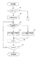
次に、このようなカール補正力制御、即ちカール補正量の調整について図6及び図7に示すフローチャートを用いて説明する。 Next, the curl correction force control, that is, the adjustment of the curl correction amount will be described with reference to the flowcharts shown in FIGS.
まず図5において、ユーザーが「+」または「−」方向に手動補正入力値を設定する。設定された値はメモリAに記憶しておく。シート搬送が開始されると、ジョブ制御部401は、トナー量からトナー像が載ったシートのカール補正量を一意に決定する。このシートが下カール補正ローラ対201に突入する前に、ユーザー入力値に応じて、一意に決定した下及び上カール補正ローラ対201,202のカール補正量の再計算が行なわれる。
First, in FIG. 5, the user sets a manual correction input value in the “+” or “−” direction. The set value is stored in the memory A. When sheet conveyance is started, the
この時、メモリからユーザー入力された値を読み出し、入力設定値が「+」または「−」の判定を行なう(701)。判定が「+」であった場合、即ち入力設定値が、シートが上カールで、このシートを上側に反らせるように修正することを示す「+」の場合(701のY)、符号を除いた手動補正入力値(オフセット値)をメモリAに保存する(702)。例えば、+5の場合には、5を保存する。 At this time, the value input by the user is read from the memory, and the input set value is determined to be “+” or “−” (701). When the determination is “+”, that is, when the input set value is “+” indicating that the sheet is curled upward and the sheet is corrected to warp upward (Y in 701), the sign is removed. The manual correction input value (offset value) is stored in the memory A (702). For example, in the case of +5, 5 is stored.
次に、現在下カール補正ローラ対201に食い込み量1〜5の補正があるかどうかを判定する(703)。ここで、既に現在下カール補正ローラ対201に食い込み量1〜5の補正があれば(703のY)、上カール補正ローラ対202の食い込み量を増やすのではなく、下カール補正ローラ対201の食い込み量を−1する(704)。
Next, it is determined whether or not the lower curl
次に、1段階分だけユーザー設定値を反映した為、メモリAの値を−1し(706)、メモリAの値が0になったか、即ちユーザー設定値を全て反映したかを判定する(707)。メモリAの値が0でない場合、即ちユーザー設定値をまだ反映し終えていない場合(707のN)、703に状態遷移して703から707の状態を繰返す。そして、メモリAの値が0になったとき(707のY)、下カール補正ローラ対201、上カール補正ローラ対202の補正量が決定する。
Next, since the user set value is reflected for one stage, the value of the memory A is decremented by -1 (706), and it is determined whether the value of the memory A becomes 0, that is, whether all the user set values are reflected ( 707). If the value of the memory A is not 0, that is, if the user set value has not yet been reflected (N in 707), the state transitions to 703 and the states from 703 to 707 are repeated. When the value of the memory A becomes 0 (Y in 707), the correction amounts of the lower curl
ところで、このようにメモリAの値を順次−1して良くと、メモリAの値が0になるまでに、下カール補正ローラ対201の食い込み量が0となる場合がある。この場合には、即ち、下カール補正ローラ対202の補正がなくなった場合には(703のN)、次に上カール補正ローラ対202の食い込み量を+1する(705)。そして、この動作を繰り返すことにより、下カール補正ローラ対201、上カール補正ローラ対202の補正量が決定する。
By the way, if the value of the memory A is sequentially decreased by −1 in this way, the amount of biting of the lower curl
一方、入力設定値の判定で、判定が「−」であった場合(701のN)、符号を除いた手動補正入力値(オフセット値)をメモリAに保存する(801)。例えば、−3の場合には、3を保存する。 On the other hand, when the determination of the input set value is “−” (N in 701), the manual correction input value (offset value) excluding the sign is stored in the memory A (801). For example, in the case of -3, 3 is stored.
次に、現在上カール補正ローラ対202に食い込み量1〜5の補正があるかどうかを判定し(802)、既に食い込み量1〜5の補正があれば(802のY)、上カール補正ローラ対202の食い込み量を−1する(803)。また、上カール補正ローラ対202の食い込み量が0であった場合、下カール補正ローラ対201の食い込み量を+1する(804)。
Next, it is determined whether or not the upper curl
次に、1段階分だけユーザー設定値を反映した為、メモリAの値を−1し(805)、メモリAの値が0になったか、即ちユーザー設定値を全て反映したかを判定する(806)。メモリAの値が0でない場合、即ちユーザー設定値をまだ反映し終えていない場合、802に状態遷移して802から806の状態を繰返す。そして、メモリAの値が0になったら下カール補正ローラ対201、上カール補正ローラ対202の補正量が決定する。
Next, since the user set value is reflected by one stage, the value of the memory A is decremented by -1 (805), and it is determined whether the value of the memory A becomes 0, that is, whether all the user set values are reflected ( 806). When the value of the memory A is not 0, that is, when the user set value has not been reflected yet, the state transitions to 802 and the state from 802 to 806 is repeated. When the value of the memory A becomes 0, the correction amounts of the lower curl
上記制御の例を挙げると、
上カール補正ローラ対:食い込み量2
下カール補正ローラ対:食い込み量0
ユーザー入力が「−2」が場合、
上カール補正ローラ対:食い込み量0
下カール補正ローラ対:食い込み量0
となる。
An example of the above control is:
Upper curl correction roller pair: Biting amount 2
Lower curl correction roller pair: 0 bite
If the user input is "-2"
Upper curl correction roller pair: 0 bite
Lower curl correction roller pair: 0 bite
It becomes.
また、ユーザー入力が「+2」の場合、
上カール補正ローラ対:食い込み量4
下カール補正ローラ対:食い込み量0
となる。
If the user input is “+2”,
Upper curl correction roller pair: biting amount 4
Lower curl correction roller pair: 0 bite
It becomes.
また、ユーザー入力が「−3」の場合、
上カール補正ローラ対:食い込み量0
下カール補正ローラ対:食い込み量1
となる。
If the user input is “-3”,
Upper curl correction roller pair: 0 bite
Lower curl correction roller pair: biting
It becomes.
このように、ユーザー入力値が幾つの値をとっても、下及び上カール補正ローラ対201,202が同時に食い込み状態となることは無く、どちらか一方は必ず食い込み量が0になる。 In this way, no matter how many values the user input value takes, the lower and upper curl correction roller pairs 201 and 202 do not bite at the same time, and the biting amount is always zero for either one of them.
そして、こうして決定した補正量分、下及び上カール補正ローラ対201,202の食い込み量を変更することにより、トナー量から自動で決定されるカール補正量に対し、ユーザー設定値を反映させる事ができる。 Then, by changing the biting amount of the lower and upper curl correction roller pairs 201 and 202 by the correction amount thus determined, the user set value can be reflected on the curl correction amount automatically determined from the toner amount. it can.
このように、手動入力された修正値を分配して下及び上カール補正ローラ対201,202のカール補正量を変更することにより、多様化するシートの種類や様々な温湿度の設置環境においても、よりカール取り品質を上げることができる。 In this manner, by manually distributing correction values and changing the curl correction amounts of the lower and upper curl correction roller pairs 201 and 202, even in a variety of sheet types and various temperature and humidity installation environments. The curl removal quality can be improved.
また、ユーザー入力により手動補正が加わった時に、下及び上カール補正ローラ対201,202のどちらかでカール補正ができるように食い込み量を分配することにより、シート搬送トルク、モータ駆動電力等を抑える事ができる。
Further, when manual correction is applied by user input, the amount of biting is distributed so that either the lower or upper curl
ところで、ユーザー入力は実際のカール補正とは関係なくユーザーが任意に入力できるため入力ミス等で、間違った入力が行なわれると、カールを付けすぎて紙詰まりになったりする。そのため、食い込み量が0のカール補正ローラに対しては、例えば最大食い込み量を3までという制限をつけるようすることが好ましい。 By the way, the user input can be arbitrarily input by the user regardless of the actual curl correction, and if an incorrect input is performed due to an input error or the like, the curl is excessively added and a paper jam occurs. For this reason, it is preferable to limit the maximum biting amount to 3, for example, a curling correction roller having a biting amount of zero.
例えば、
上カール補正ローラ対:食い込み量1
下カール補正ローラ対:食い込み量0
ユーザー入力が「−5」の場合、
上カール補正ローラ:食い込み量0
下カール補正ローラ:食い込み量4
となる。
For example,
Upper curl correction roller pair: biting
Lower curl correction roller pair: 0 bite
When user input is “−5”,
Upper curl correction roller: Biting
Lower curl correction roller: Biting amount 4
It becomes.
この場合、下カール補正ローラ対通過後、下カールが大きすぎてシート排出等ができなくなる可能性がある。したがって、このように自動制御の結果、食い込み量0と決定した補正ローラに対して、ユーザー入力値の反映は、食い込み量3までとする。
In this case, after passing through the lower curl correction roller pair, there is a possibility that the lower curl is too large to discharge the sheet. Therefore, the user input value is reflected up to the bite amount 3 for the correction roller determined to have the
上記の例では食い込み量4に制限をかけ、食い込み量3とする。 In the above example, the biting amount 4 is limited to the biting amount 3.
この結果、
上カール補正ローラ対:食い込み量0
下カール補正ローラ対:食い込み量3
のように、カール補正量が決定される。
As a result,
Upper curl correction roller pair: 0 bite
Lower curl correction roller pair: bite amount 3
As described above, the curl correction amount is determined.
なお、これまでの説明においては、カール取り補正量(食い込み量)をトナー量のみから導き出している。しかし、シート厚み、物性値、又はシートサイズから食い込み量から導き出しても良い。また、それぞれの情報を組み合わせてカール補正量を決めてもよい。つまり、例えばトナー量とシート厚みとからジョブ制御部401が自動的にカール補正量を決定するように構成してもよい。
In the description so far, the curl correction amount (bite-in amount) is derived only from the toner amount. However, the amount of biting may be derived from the sheet thickness, physical property value, or sheet size. Further, the curl correction amount may be determined by combining each information. In other words, for example, the
また、自動制御の結果、食い込み量0(補正量を最小値)と決定した補正ローラに対して、ユーザー入力値を反映した状態の食い込み量を、3を上限とした例をあげたが、上限値は、シートの種類によって変更するようにしても良い。例えば、薄いシートの場合には上限値を3までとし、厚いシートの場合には上限値を4とするようにしてもよい。 In addition, for the correction roller determined to be the bite amount 0 (correction amount is the minimum value) as a result of automatic control, the bite amount in the state reflecting the user input value is given as an upper limit. The value may be changed depending on the type of sheet. For example, the upper limit may be set to 3 for a thin sheet, and the upper limit may be set to 4 for a thick sheet.
なお、本実施の形態では、自動制御の結果、食い込み量が設定されている補正ローラ対に対しては上限を設けずに、補正ローラ対に設定できる最大の食い込み量となるような修正値が入力された場合にもそれに対応するように動作させる。 In the present embodiment, as a result of automatic control, a correction value is set such that the maximum bite amount that can be set for the correction roller pair is set without setting an upper limit for the correction roller pair for which the bite amount is set. When it is input, it is operated so as to respond to it.
つまり、上記の例で言えば、自動制御の結果、食い込み量0とされた下カール補正ローラ対に対しては入力された修正値に上限を設ける。一方、自動制御の結果、食い込み量1とされた上カール補正ローラ対に対しては、入力された修正値に上限値を設けずに上カール補正ローラ対の最大の補正力を得られるまで食い込ませることを許容する。
That is, in the above example, an upper limit is set to the input correction value for the lower curl correction roller pair in which the bite amount is 0 as a result of the automatic control. On the other hand, as a result of the automatic control, the upper curl correction roller pair having the biting
さらに、自動制御の結果、食い込み量0と決定した補正ローラに対して、ユーザー入力値の反映は、食い込み量3を上限として、例えば食い込み量が4となる修正値が入力されたとしても、実際の装置の動作としては食い込み量3を超えないようにした。 Further, as a result of automatic control, the user input value is reflected on the correction roller determined to have a bite amount of 0, even if a correction value with a bite amount of 4, for example, is input as an upper limit. As for the operation of this device, the biting amount 3 was not exceeded.
しかしながら、ユーザーの入力部(操作部400)において、自動制御の結果、食い込み量0(補正量最小)と決定した補正ローラに対して、上限食い込み量を超える修正値をユーザーが入力できないようにしても良い。なお、この修正値の上限はシートの種類に応じて変更されることから、シートの種類に応じて変更される上限食い込み量を超える修正値をユーザーが入力できないようにすることがこの好ましい。 However, in the user's input unit (operation unit 400), the correction value exceeding the upper limit biting amount cannot be input to the correction roller determined to be the biting amount 0 (minimum correction amount) as a result of automatic control. Also good. Since the upper limit of the correction value is changed according to the sheet type, it is preferable to prevent the user from inputting a correction value that exceeds the upper limit bite amount that is changed according to the sheet type.
そして、食い込み量0(補正量最小)と自動補正により決定されたカール補正ローラ対に対して、ユーザー入力による食い込み量の加算に制限を設けることにより、ユーザー入力ミス等によるカールが要因で発生するシート詰まり等を抑えることができる。 Further, a curl due to a user input error or the like occurs due to a restriction on the addition of the bite amount by the user input to the curl correction roller pair determined by the bite amount 0 (minimum correction amount) and automatic correction. Sheet clogging and the like can be suppressed.
100 装置本体
100A 画像形成装置
100B 画像形成部
145 定着器
200 カール取り装置
200A シート搬送装置
201 下カール補正ローラ対
202 上カール補正ローラ対
202a スポンジローラ
202b 下ローラ
202e 偏心カム
300 操作部
401 ジョブ制御部
100 apparatus
Claims (9)
前記第1カール補正手段のカール補正量及び前記第2カール補正手段のカール補正量を決定するカール補正量決定手段と、
前記カール補正量決定手段によって決定されたカール補正量を修正するために、修正するカールの方向とカール量とに係る修正値を手動入力するための入力部と、を備え、
予め前記カール補正量決定手段が決定した前記第1カール補正手段のカール補正量及び前記第2カール補正手段のカール補正量を前記入力部に入力された修正値に基づいて変更する際に、前記入力部に入力された修正値が、前記第1カール補正手段のカール補正量及び前記第2カール補正手段のカール補正量の一方を減少することで対応できない修正値であった場合には、前記一方のカール補正手段の補正量を最小とし、且つ、他方のカール補正手段の補正量を増加させることを特徴とするシート搬送装置。 A first curl correcting unit that corrects a curl in a first direction of the sheet; and a second curl that is provided downstream of the first curl correcting unit and corrects a curl in a second direction opposite to the first direction of the sheet. In the sheet conveying apparatus that conveys the sheet while correcting the curl by the correcting means,
A curl correction amount determination unit for determining a curl correction amount of the first curl correction unit and a curl correction amount of the second curl correction unit;
An input unit for manually inputting a correction value related to the direction and curl direction of the curl to be corrected in order to correct the curl correction amount determined by the curl correction amount determining means;
When changing the curl correction amount of the first curl correction unit and the curl correction amount of the second curl correction unit determined by the curl correction amount determination unit in advance based on the correction value input to the input unit, When the correction value input to the input unit is a correction value that cannot be handled by reducing one of the curl correction amount of the first curl correction unit and the curl correction amount of the second curl correction unit, A sheet conveying apparatus characterized by minimizing a correction amount of one curl correcting unit and increasing a correction amount of the other curl correcting unit .
前記修正値に対応させようとすると前記第1及び第2カール補正手段のカール補正量が上限値を超える場合には、前記第1及び第2カール補正手段のカール補正量を上限値に制限することを特徴とする請求項1又は2記載のシート搬送装置。 An upper limit is provided for the curl correction amount of the first curl correction unit and the curl correction amount of the second curl correction unit,
If the curl correction amount of the first and second curl correction means exceeds the upper limit value when trying to correspond to the correction value, the curl correction amount of the first and second curl correction means is limited to the upper limit value. The sheet conveying apparatus according to claim 1 or 2,
Priority Applications (4)
| Application Number | Priority Date | Filing Date | Title |
|---|---|---|---|
| JP2006183895A JP4777165B2 (en) | 2006-07-03 | 2006-07-03 | Sheet conveying apparatus and image forming apparatus |
| US11/766,635 US7860447B2 (en) | 2006-07-03 | 2007-06-21 | Curling device and image forming apparatus |
| CN2007101263907A CN101100247B (en) | 2006-07-03 | 2007-07-03 | curling device and imaging device |
| CN201110341087.5A CN102358533B (en) | 2006-07-03 | 2007-07-03 | Curling device and image forming apparatus |
Applications Claiming Priority (1)
| Application Number | Priority Date | Filing Date | Title |
|---|---|---|---|
| JP2006183895A JP4777165B2 (en) | 2006-07-03 | 2006-07-03 | Sheet conveying apparatus and image forming apparatus |
Publications (3)
| Publication Number | Publication Date |
|---|---|
| JP2008013284A JP2008013284A (en) | 2008-01-24 |
| JP2008013284A5 JP2008013284A5 (en) | 2009-08-27 |
| JP4777165B2 true JP4777165B2 (en) | 2011-09-21 |
Family
ID=39034743
Family Applications (1)
| Application Number | Title | Priority Date | Filing Date |
|---|---|---|---|
| JP2006183895A Active JP4777165B2 (en) | 2006-07-03 | 2006-07-03 | Sheet conveying apparatus and image forming apparatus |
Country Status (3)
| Country | Link |
|---|---|
| US (1) | US7860447B2 (en) |
| JP (1) | JP4777165B2 (en) |
| CN (2) | CN101100247B (en) |
Families Citing this family (6)
| Publication number | Priority date | Publication date | Assignee | Title |
|---|---|---|---|---|
| JP2009203067A (en) * | 2008-02-29 | 2009-09-10 | Canon Inc | Sheet carrying device, control method for sheet carrying device, storage medium, and program |
| JP4605281B2 (en) * | 2008-09-16 | 2011-01-05 | コニカミノルタビジネステクノロジーズ株式会社 | Image forming system |
| JP5560685B2 (en) * | 2009-12-10 | 2014-07-30 | 富士ゼロックス株式会社 | Image forming apparatus |
| JP5498912B2 (en) * | 2010-01-27 | 2014-05-21 | 京セラドキュメントソリューションズ株式会社 | Image forming apparatus |
| US8862047B2 (en) * | 2010-03-25 | 2014-10-14 | Kyocera Document Solutions Inc. | Sheet curl correction apparatus and image forming apparatus |
| JP7003440B2 (en) * | 2016-07-13 | 2022-01-20 | セイコーエプソン株式会社 | Intermediate unit, post-processing equipment, and printing equipment |
Family Cites Families (13)
| Publication number | Priority date | Publication date | Assignee | Title |
|---|---|---|---|---|
| JPS6327372A (en) | 1986-07-16 | 1988-02-05 | Canon Inc | Image former |
| JP2902130B2 (en) | 1990-12-28 | 1999-06-07 | 株式会社リコー | Decurling device |
| JP2945541B2 (en) | 1992-05-12 | 1999-09-06 | キヤノン株式会社 | Image forming device |
| JP3049628B2 (en) | 1992-11-13 | 2000-06-05 | 富士ゼロックス株式会社 | Control device for curl correction device of image forming apparatus |
| US5749040A (en) * | 1995-07-20 | 1998-05-05 | Canon Kabushiki Kaisha | Image forming apparatus capable of correcting curl of sheet |
| JP2000229758A (en) * | 1999-02-09 | 2000-08-22 | Fuji Xerox Co Ltd | Curl compensation device and picture image formation device |
| JP2002080157A (en) * | 2000-09-06 | 2002-03-19 | Fuji Xerox Co Ltd | Curl correcting device |
| JP2002316761A (en) * | 2001-04-23 | 2002-10-31 | Fuji Xerox Co Ltd | Image forming device |
| JP3962605B2 (en) * | 2002-02-28 | 2007-08-22 | キヤノン株式会社 | Sheet processing apparatus and image forming apparatus |
| JP2005008320A (en) * | 2003-06-18 | 2005-01-13 | Canon Inc | Image forming device |
| JP4065538B2 (en) * | 2003-09-22 | 2008-03-26 | キヤノン株式会社 | Curl correction device and image forming apparatus |
| JP4111193B2 (en) * | 2004-12-28 | 2008-07-02 | ブラザー工業株式会社 | Curl correction device and image forming apparatus |
| JP4533230B2 (en) * | 2005-04-28 | 2010-09-01 | キヤノン株式会社 | Image forming apparatus |
-
2006
- 2006-07-03 JP JP2006183895A patent/JP4777165B2/en active Active
-
2007
- 2007-06-21 US US11/766,635 patent/US7860447B2/en active Active
- 2007-07-03 CN CN2007101263907A patent/CN101100247B/en not_active Expired - Fee Related
- 2007-07-03 CN CN201110341087.5A patent/CN102358533B/en active Active
Also Published As
| Publication number | Publication date |
|---|---|
| CN101100247A (en) | 2008-01-09 |
| US7860447B2 (en) | 2010-12-28 |
| JP2008013284A (en) | 2008-01-24 |
| CN101100247B (en) | 2011-12-21 |
| US20080159795A1 (en) | 2008-07-03 |
| CN102358533A (en) | 2012-02-22 |
| CN102358533B (en) | 2014-10-08 |
Similar Documents
| Publication | Publication Date | Title |
|---|---|---|
| JP4933160B2 (en) | Image forming system, image forming apparatus, clear image forming apparatus, and control apparatus | |
| US9229411B2 (en) | Sheet curl correction apparatus and image forming apparatus | |
| JP5983686B2 (en) | Paper conveying apparatus and image forming apparatus | |
| JP4777165B2 (en) | Sheet conveying apparatus and image forming apparatus | |
| US8588674B2 (en) | Image-forming apparatus and method for controlling image-forming apparatus | |
| US7941089B2 (en) | Image forming system and clear coating apparatus | |
| JP2007322818A (en) | Image forming system | |
| JP2009249169A (en) | Image forming apparatus and curl straightening device | |
| JP2006343751A (en) | Image forming apparatus and image forming method | |
| JP6570810B2 (en) | Paper conveying apparatus and image forming apparatus | |
| US8190047B2 (en) | Image forming apparatus | |
| JP6098356B2 (en) | Image reading apparatus, image forming system, and program | |
| JP6911615B2 (en) | Image forming apparatus and control method of image forming apparatus | |
| JP4786502B2 (en) | Document reading apparatus and image forming apparatus using the same | |
| JP2001213563A (en) | Recording material processing device, image forming device used in it, and curl correcting device | |
| JP6299669B2 (en) | Image forming apparatus | |
| JP4834603B2 (en) | Image processing apparatus and image forming apparatus | |
| CN111123674A (en) | Post-processing apparatus and image forming apparatus | |
| JP2009035345A (en) | Sheet processor and image forming apparatus | |
| JP2005263348A (en) | Paper delivery mechanism of image forming apparatus | |
| JP5464139B2 (en) | Image forming apparatus | |
| JP7047267B2 (en) | Image forming device and transfer control method | |
| JP2007127963A (en) | Image forming apparatus | |
| JP6953793B2 (en) | Image forming device and transfer control method | |
| JP6988167B2 (en) | Image forming device and transfer control method |
Legal Events
| Date | Code | Title | Description |
|---|---|---|---|
| A521 | Written amendment |
Free format text: JAPANESE INTERMEDIATE CODE: A523 Effective date: 20090703 |
|
| A621 | Written request for application examination |
Free format text: JAPANESE INTERMEDIATE CODE: A621 Effective date: 20090703 |
|
| A977 | Report on retrieval |
Free format text: JAPANESE INTERMEDIATE CODE: A971007 Effective date: 20110330 |
|
| A131 | Notification of reasons for refusal |
Free format text: JAPANESE INTERMEDIATE CODE: A131 Effective date: 20110405 |
|
| A521 | Written amendment |
Free format text: JAPANESE INTERMEDIATE CODE: A523 Effective date: 20110606 |
|
| TRDD | Decision of grant or rejection written | ||
| A01 | Written decision to grant a patent or to grant a registration (utility model) |
Free format text: JAPANESE INTERMEDIATE CODE: A01 Effective date: 20110628 |
|
| A01 | Written decision to grant a patent or to grant a registration (utility model) |
Free format text: JAPANESE INTERMEDIATE CODE: A01 |
|
| A61 | First payment of annual fees (during grant procedure) |
Free format text: JAPANESE INTERMEDIATE CODE: A61 Effective date: 20110629 |
|
| R150 | Certificate of patent or registration of utility model |
Free format text: JAPANESE INTERMEDIATE CODE: R150 Ref document number: 4777165 Country of ref document: JP Free format text: JAPANESE INTERMEDIATE CODE: R150 |
|
| FPAY | Renewal fee payment (event date is renewal date of database) |
Free format text: PAYMENT UNTIL: 20140708 Year of fee payment: 3 |