JP6999500B2 - Analysis equipment - Google Patents
Analysis equipment Download PDFInfo
- Publication number
- JP6999500B2 JP6999500B2 JP2018106834A JP2018106834A JP6999500B2 JP 6999500 B2 JP6999500 B2 JP 6999500B2 JP 2018106834 A JP2018106834 A JP 2018106834A JP 2018106834 A JP2018106834 A JP 2018106834A JP 6999500 B2 JP6999500 B2 JP 6999500B2
- Authority
- JP
- Japan
- Prior art keywords
- wavelength
- sample
- light
- component
- sample component
- Prior art date
- Legal status (The legal status is an assumption and is not a legal conclusion. Google has not performed a legal analysis and makes no representation as to the accuracy of the status listed.)
- Active
Links
Images


Classifications
-
- G—PHYSICS
- G01—MEASURING; TESTING
- G01N—INVESTIGATING OR ANALYSING MATERIALS BY DETERMINING THEIR CHEMICAL OR PHYSICAL PROPERTIES
- G01N21/00—Investigating or analysing materials by the use of optical means, i.e. using sub-millimetre waves, infrared, visible or ultraviolet light
- G01N21/17—Systems in which incident light is modified in accordance with the properties of the material investigated
- G01N21/25—Colour; Spectral properties, i.e. comparison of effect of material on the light at two or more different wavelengths or wavelength bands
- G01N21/27—Colour; Spectral properties, i.e. comparison of effect of material on the light at two or more different wavelengths or wavelength bands using photo-electric detection ; circuits for computing concentration
-
- G—PHYSICS
- G01—MEASURING; TESTING
- G01N—INVESTIGATING OR ANALYSING MATERIALS BY DETERMINING THEIR CHEMICAL OR PHYSICAL PROPERTIES
- G01N35/00—Automatic analysis not limited to methods or materials provided for in any single one of groups G01N1/00 - G01N33/00; Handling materials therefor
- G01N35/10—Devices for transferring samples or any liquids to, in, or from, the analysis apparatus, e.g. suction devices, injection devices
Description
本発明は、試料内に含まれる試料成分を分析する分析装置に関する。 The present invention relates to an analyzer that analyzes a sample component contained in a sample.
生化学・免疫自動分析装置の進歩とともに、検体の前処理や搬送技術の自動化についても開発が進んでいる。検体数は年々増加しているにも関わらず、技師の人数は横ばいであり、検体の前処理を自動化するシステムが市場ニーズとなっている。また、新たな検査法が開発されるなどによって検査項目は多様化しており、種々の検査項目に対して自動で前処理を実施するシステムの重要性も高まっている。しかしながら、検体の前処理工程は必ずしも全てが自動化されておらず、技師による手作業が不可欠な部分も残っているのが現状である。 With the progress of biochemical and immunoassays, the development of sample pretreatment and automation of transport technology is also progressing. Although the number of samples is increasing year by year, the number of engineers is flat, and a system that automates the pretreatment of samples has become a market need. In addition, inspection items are diversifying due to the development of new inspection methods, and the importance of a system that automatically performs pretreatment for various inspection items is increasing. However, the pretreatment process of the sample is not always automated, and there are still some parts where manual work by a technician is indispensable.
一般的な検体検査においては専用の容器が用意されており、患者の生体試料は当該容器で採取され、前処理が実施される。例えば、試料が血液の場合、採取した血液を採血管に投入する。当該採血管に対し遠心分離を施すことにより、血液を血餅と血清とに分離、もしくは血球と血しょうとに分離し、これにより分析に必要な成分である血清もしくは血しょうを得ることができる。 In general sample inspection, a dedicated container is prepared, and the biological sample of the patient is collected in the container and pretreated. For example, when the sample is blood, the collected blood is put into a blood collection tube. By centrifuging the blood collection tube, blood can be separated into blood clots and serum, or blood cells and plasma, thereby obtaining serum or plasma, which is a component necessary for analysis. ..
得られた血清や血しょう等の生体由来分子を含む試料の液体成分に対して検査を実施する前に必要な処理として、液体成分の位置や量を検出する処理がある。液体量が不明の場合、分注時にプローブが分離剤や血球に突き刺さり、詰まりによるエラーが生じることがあるからである。前処理の段階で液体成分の量を検出できれば、プローブ高さを制御して詰まりによるエラーを回避することができる。さらに、液体成分量が分析に必要な量を満たさない場合、分析項目に優先順位を設けて分注量を決定することができる。したがって前処理の段段で液体成分量を検出することができれば、検査の効率化が見込まれる。 As a treatment necessary before conducting an inspection on the liquid component of the obtained sample containing biological molecules such as serum and plasma, there is a treatment for detecting the position and amount of the liquid component. This is because if the amount of liquid is unknown, the probe may pierce the separating agent or blood cells during dispensing, causing an error due to clogging. If the amount of liquid component can be detected at the pretreatment stage, the probe height can be controlled to avoid errors due to clogging. Furthermore, if the amount of liquid component does not meet the amount required for analysis, the analysis items can be prioritized to determine the amount to be dispensed. Therefore, if the amount of liquid component can be detected in the pretreatment stage, the efficiency of inspection is expected to be improved.
血液凝固分析においては、バフィーコートと呼ばれる赤血球と血しょうの中間層にあたる層を避けて分注する必要がある。遺伝子検査においては、バフィーコート中の成分に着目して分注したいという要求もある。したがって液体成分の位置を検出する技術は、生体試料の分析において非常に重要である。 In blood coagulation analysis, it is necessary to avoid the layer called the buffy coat, which is the intermediate layer between red blood cells and plasma. In genetic testing, there is also a demand to pay attention to the components in the buffy coat and dispense them. Therefore, the technique of detecting the position of a liquid component is very important in the analysis of a biological sample.
血清や血しょう等の液体成分量を検出、あるいは液体成分の層位置を検出する技術として、下記特許文献1~4が挙げられる。特許文献1は、血清を透過し血餅に遮られる第1の光ビームと血清および血餅に遮られる第2の光ビームを用い、前記第1、第2のビームが容器を透過した光を検出し、両者の透過光量の差分から試料層位置を決定する方法を開示している。特許文献2は、血清に特有に吸収される第1の光ビーム、血清に特有に吸収されない第2、および第3の光ビームを用いて、各吸光度の差分値より試料層位置を決定する方法を開示している。特許文献3は、第1および第2の波長成分からなる光ビームを試料に照射し、サンプルを透過した光を受光した後に信号処理により第1および第2の成分を分離し、第1および第2の波長成分の商から試料層位置を決定する方法を開示している。特許文献4は、試料を透過した第1波長成分と第2波長成分の商の1次導関数を求めるとともに、その1次導関数に基づき液面間の境界を求める手法を開示している。 The following Patent Documents 1 to 4 can be mentioned as techniques for detecting the amount of liquid components such as serum and plasma, or detecting the layer position of liquid components. Patent Document 1 uses a first light beam that penetrates serum and is blocked by a blood clot and a second light beam that is blocked by serum and blood clots, and the first and second beams transmit light that has passed through a container. It discloses a method of detecting and determining the sample layer position from the difference in the amount of transmitted light between the two. Patent Document 2 is a method of determining a sample layer position from a difference value of each absorbance using a first light beam that is specifically absorbed by serum, a second light beam that is not specifically absorbed by serum, and a third light beam. Is disclosed. In Patent Document 3, a sample is irradiated with a light beam composed of first and second wavelength components, and after receiving light transmitted through the sample, the first and second components are separated by signal processing, and the first and second components are separated. A method for determining the sample layer position from the quotient of the wavelength component of 2 is disclosed. Patent Document 4 discloses a method of obtaining a first derivative of the quotient of the first wavelength component and the second wavelength component transmitted through a sample, and finding a boundary between liquid levels based on the first derivative.
検体検査の前処理においては、一般に試料容器の蓋をあけずに計測を実施する要求がある。蓋を開けた際に試料がこぼれて試料間の汚染が生じることを防止するためである。また試料の容器には、例えばバーコードラベル等の検体識別用情報が印字されている場合も多く、中身を視認し難い試料であっても計測を実施する要求がある。さらには、試料の状態は用いる採血管によって異なる。分離剤入りの試験管であれば試料は血餅/分離剤/血清/空気の4層構造を有し、凝固分析用の試験管であれば試料は血球/血しょう/空気の3層構造を有する。このように試料ごとに成分層の構成が異なる場合であっても、各成分層の高さを検出する必要がある。 In the pretreatment of the sample test, it is generally required to carry out the measurement without opening the lid of the sample container. This is to prevent the sample from spilling when the lid is opened and causing contamination between the samples. Further, in many cases, sample identification information such as a bar code label is printed on the sample container, and there is a demand to measure even a sample whose contents are difficult to visually recognize. Furthermore, the condition of the sample depends on the blood collection tube used. If the test tube contains a separating agent, the sample has a four-layer structure of blood clot / separating agent / serum / air, and if it is a test tube for coagulation analysis, the sample has a three-layer structure of blood cells / plasma / air. Have. Even when the composition of the component layer is different for each sample as described above, it is necessary to detect the height of each component layer.
特許文献1と2に記載された技術は、各生体試料層においてそれぞれ異なる透過率を有する複数の波長の光ビームを用いて、光透過量を計測する。この技術は、光透過量の差分値を算出することによって、ラベルにおいて光が散乱する影響を取り除いて試料層の境界面位置を算出することができる。一方でこの技術は計測に用いる光ビームの数に応じた投光装置および受光装置が必要であるので、装置が大型かつ高価になり、調整等も容易ではない。また、光ビームが散乱すること等によって、光検出時に複数の光ビームが相互に干渉し、試料層の境界面位置の計測精度誤差が大きくなる場合もある。 The techniques described in Patent Documents 1 and 2 measure the amount of light transmission using light beams having a plurality of wavelengths having different transmittances in each biological sample layer. This technique can calculate the boundary surface position of the sample layer by removing the influence of light scattering on the label by calculating the difference value of the light transmittance. On the other hand, since this technology requires a light projecting device and a light receiving device according to the number of light beams used for measurement, the device becomes large and expensive, and adjustment and the like are not easy. Further, due to the scattering of light beams or the like, a plurality of light beams may interfere with each other at the time of light detection, and the measurement accuracy error of the boundary surface position of the sample layer may become large.
特許文献3に記載された技術は、第1および第2の波長成分からなる光ビームを用いて光透過量を計測する。この技術は、位相の変調および復調を用いて、光検出後に信号処理によって第1および第2の波長成分に分離することにより、上記異なる波長の光ビームが相互に干渉する課題を解決している。しかしながらこの技術は、入射光の波長である第1および第2の波長成分にしか分離することができない。例えば、光源の波長帯よりも狭い波長の光を取り出すことは困難である。血液のような生体試料は、個人の健康状態や試料の取得環境に応じて中身の成分が様々であり、特徴的な光の吸収および透過波長は数nm単位で異なる。したがってこの技術は、試料層の成分や境界面位置を信頼性高くかつ正確に検出する際にはいまだ課題が残る。 The technique described in Patent Document 3 measures the amount of transmitted light using a light beam composed of first and second wavelength components. This technique solves the problem that light beams of different wavelengths interfere with each other by separating them into first and second wavelength components by signal processing after light detection using phase modulation and demodulation. .. However, this technique can only separate the first and second wavelength components, which are the wavelengths of the incident light. For example, it is difficult to extract light having a wavelength narrower than the wavelength band of the light source. Biological samples such as blood have various contents depending on the health condition of the individual and the environment in which the sample is obtained, and the characteristic light absorption and transmission wavelengths differ by several nm. Therefore, this technique still has problems in detecting the components of the sample layer and the position of the boundary surface with high reliability and accuracy.
特許文献4に記載された技術は、試料を透過した第1波長成分と第2波長成分の商の1次導関数を求めるとともに、その1次導関数に基づき液面間の境界を求めている(同文献のClaims1-2、0064-0065)。この手法は、特許文献1~2と同様に波長が異なる複数の光源を用いることが前提になっていると考えられるので(特許文献4の0027、light source2,3)、特許文献1~2と同様の課題がある。また特許文献4の手法は、第1波長成分と第2波長成分の商を求めることが前提になっており(同文献の0007、0064-0065)、したがって検出することができる試料成分はこれらの波長によって制約されると考えられる。 The technique described in Patent Document 4 obtains the first derivative of the quotient of the first wavelength component and the second wavelength component transmitted through the sample, and also obtains the boundary between the liquid levels based on the first derivative. (Clamms 1-2, 0064-0065 of the same document). Since this method is considered to be premised on using a plurality of light sources having different wavelengths as in Patent Documents 1 and 2 (0027 of Patent Document 4, light sources 2 and 3), Patent Documents 1 and 2 and There are similar challenges. Further, the method of Patent Document 4 is premised on finding the quotient of the first wavelength component and the second wavelength component (0007, 0064-0065 in the same document), and therefore the sample components that can be detected are these. It is considered to be constrained by wavelength.
本発明は、上記課題に鑑みてなされたものであり、複数の光源を用いることなく、容器内の試料成分および試料成分間の境界面位置を精度よく検出することができる分析装置を提供することを目的とするものである。 The present invention has been made in view of the above problems, and provides an analyzer capable of accurately detecting a sample component in a container and a boundary surface position between the sample components without using a plurality of light sources. Is the purpose.
本発明に係る分析装置は、試料から分離された1以上の試料成分を層状に収容した容器に対して光を照射し、試料を透過した光の光強度が最大となる波長を前記層ごとに特定することにより、前記容器が収容している各前記試料成分を特定する。 The analyzer according to the present invention irradiates a container containing one or more sample components separated from a sample in a layered manner with light, and sets the wavelength at which the light intensity of the light transmitted through the sample is maximum for each layer. By specifying, each of the sample components contained in the container is specified.
本発明に係る分析装置によれば、複数の光源を用いることなく、容器内の試料成分層または試料層間の境界面位置を高精度に検出することができる。本発明に関連するさらなる特徴は、本明細書の記述、添付図面から明らかになる。上記した以外の課題、構成および効果は、以下の実施の形態の説明により明らかにされる。 According to the analyzer according to the present invention, the position of the boundary surface between the sample component layer or the sample layer in the container can be detected with high accuracy without using a plurality of light sources. Further features relating to the present invention will become apparent from the description herein and the accompanying drawings. Issues, configurations and effects other than those described above will be clarified by the following description of embodiments.
<実施の形態1:装置構成>
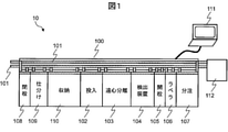
図1は、本発明の実施形態1に係る生体試料分析装置10の概略を示す構成図である。生体試料分析装置10は、患者から採取した生体試料を前処理システム100によって前処理し、自動分析装置112によってその試料を分析する装置である。
<Embodiment 1: Device Configuration>
FIG. 1 is a block diagram showing an outline of the
生体試料分析装置10は、前処理システム100、制御用PC111、自動分析装置112を備える。前処理システム100は、搬送ライン101、投入モジュール102、遠心分離モジュール103、検出装置104、開栓モジュール105、ラベラ106(例えばバーコードなどを用いる)、分注モジュール107、閉栓モジュール108、仕分けモジュール109、収納モジュール110を備える。制御用PC111は、前処理システム100を含む装置全体を制御する。自動分析装置112は、生体試料の成分を例えば定量分析によって分析する。
The
次に、生体試料の前処理および分析に関する一連の工程について説明する。はじめに、患者から採取された生体試料(例えば血液や尿)は、試験管に入れられた後、投入モジュール102に投入される。一般に、採血および投入モジュール102への検体の投入はユーザーの手作業によってなされる。その後の検体は、搬送ライン101の上に載って、遠心分離モジュール103、検出装置104、開栓モジュール105、ラベラ106、分注モジュール107、閉栓モジュール108、仕分けモジュール109、収納モジュール110の間で移動される。
Next, a series of steps related to the pretreatment and analysis of the biological sample will be described. First, a biological sample (for example, blood or urine) collected from a patient is placed in a test tube and then charged into a
遠心分離モジュール103は、投入された検体に対して遠心分離を実施する。生体試料が血液であり、試験管の中に分離剤が入っている場合、試料は遠心分離によって、分離剤を挟んで血餅の層と血清の層とに分離される。生体試料が血液であり、試験管の中に分離剤が入っていない場合、試料は遠心分離によって、血球の層と血しょうの層とに分離される。
The
検出装置104は、生体試料層の成分、生体試料層の位置、生体試料の液量などを検出する。血清成分にヘモグロビンが溶出する溶血成分が検出され、または生体試料や試料量が極めて少ないと判定された場合、検体は仕分けモジュール109まで移動され、エラー検体に分類される。それ以外の検体の場合は、生化学や免疫分析を実施するため、検体は搬送ライン101によって開栓モジュール105に移動される。
The
開栓モジュール105は、検体の栓を開栓する。分注モジュール107は、遠心分離された検体(親検体)を、自動分析装置112等で分析するために小分け(子検体)する。ラベラ106は、その小分けの容器にバーコードラベルを貼付する。閉栓モジュール108は、各試料容器の栓を閉栓する。仕分けモジュール109は、親検体および子検体を仕分けし、親検体の場合には収納モジュール110へ子検体の場合には自動分析装置112まで移動させる。自動分析装置112はその検体の各試料成分についての定量分析などを実施する。自動分析装置112と前処理システム100との間で、一部の構成要素(例えば分注モジュール107)を共用してもよい。
The
図2は、検出装置104の構成図である。記載の便宜上、試料を収容する試験管204を図面上に併記した。検出装置104は、光源200、波長分光部201、受光部202、コンピュータ203(「制御装置」「演算装置」に相当)、駆動装置205、把持装置206を備える。
FIG. 2 is a block diagram of the
把持装置206は、光源200と受光部202によって挟まれるように試験管204を配置する。光源200は測定対象の試料を含む試験管204の側面から光を照射する。駆動装置205は、試験管204を上下方向に移動させることにより、光源200からの光が試験管204に対して照射される高さ方向の位置を変化させる。波長分光部201は、試料を透過した光源200からの光から特定の波長成分の光を分離する。受光部202はその分離された波長成分の透過光量(光強度)を測定する。
The
コンピュータ203は、波長分光部201/受光部202/駆動装置205と接続されこれらを制御する。例えばコンピュータ203からの指示にしたがって、波長分光部201は分離する光の波長帯を変更する。受光部202からの透過光出力は、例えばA/D変換された後、コンピュータ203によって信号処理が施される。駆動装置205は、試験管204と光源200との間の高さ方向における相対的位置関係(波長分光部201と受光部202の高さ方向の位置も光源200の位置に合わせる)を変化させ、これにより試験管204上の特定の高さにおける透過光量が測定される。表示機207は受光部202による測定結果を出力する。例えば波長毎の光透過量、特定の高さに配置されている試料成分、などを出力する。
The
計測対象が血液である場合、試験管204には例えば、血餅208、分離剤209、血清210、空気211が含まれ、キャップ212により蓋がされる。試験管204の外周には、試験管204の種類や検査項目もしくは患者の識別用途に用いられる、紙製やシール製のラベル213が貼付される場合がある。ラベル213には、バーコードや文字等が印刷されている場合もある。
When the measurement target is blood, the
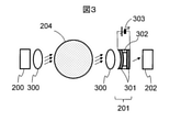
図3は、試料検出装置における波長分光部201とその周辺素子の構成例である。光源200は試験管204の側方に配置され、試験管204の側面に対して光を照射する。照射された光は、試料を透過するようにレンズ300を用いて集光されることが好ましい。光源200としては、計測する試料(ここでは血清)の光吸収ピークが存在する領域付近の波長を持った光を発生させるものを用いる。具体的には、1450nmに血清の吸収ピークが存在するので、1300~1700nmの範囲の波長が好ましく、本実施形態1では中心波長1450nmの発光ダイオードを用いた。この中心波長の光は、血清の主成分である水によく吸収され、中心波長よりも短波長側の光は水には透過する性質をもつ。またこの波長帯の光は、特に中心波長よりも長波長側で分離剤を透過する性質を持ち、全波長帯で血餅に吸収される性質をもつ。
FIG. 3 is a configuration example of the wavelength
光源200としては、レーザ、発光ダイオード、ハロゲンランプのいずれを用いてもよい。レーザの場合には高い指向性と高出力が得られ、発光ダイオードの場合にはコストメリットがある。複数のレーザや発光ダイオードを隣合わせに配置し、あるいはレンズやファイバ等により合波することにより、広い発光波長領域をもつ光源を用いてもよい。周囲の温度等に依存して光源200の発光波長は僅かに変化するので、光源200付近に温度センサを配置し、温度に応じて制御電圧を変更し、あるいは光源200を一定温度に制御することが好ましい。
As the
光源200からの光は、試料を含む試験管204を透過した後、再度レンズ300により集光され、波長分光部201を透過する。波長分光部201は、入射した光の中から任意の波長の光を取り出す機能を有している。波長分光部201としては例えば、光の干渉を利用して特定波長の光を取り出すフィルタ、波長選択性をもつ材料の薄膜を利用した光学フィルタ、光を波長毎に空間的に分離可能なプリズムや回折格子、などが用いられる。後述の図4Cに示すように血液は近接した波長領域において光強度ピークを有するので、波長分光部201は半値全幅20nm程度もしくはそれよりも小さい波長分解能をもつことが好ましい。本実施形態1では、高波長分解能およびコストメリットが大きく、装置構成を簡素化することができる、光の干渉を利用したファブリ・ペローフィルタを用いた。ファブリ・ペローフィルタを用いた場合は、受光部202の表面積を大きくとることができるので、試験管204表面のラベルによって光が散乱する場合に有効である。回折格子を用いた場合は、高い波長分解能で計測する場合に有効である。
The light from the
波長分光部201は、例えば、2つのミラー薄膜301、中間層302、電圧制御装置303から構成される。2つのミラー薄膜301は厚さ数μmの中間層302に挟まれて対向しており、ミラー間のギャップに応じて特定波長の光を透過できる。電圧制御装置303により静電引力を制御し、2つのミラー薄膜301間の距離を変更することにより、任意の波長をもつ光を透過できる。図3に示す例においては、電圧制御装置303に印加する電圧を大きくするほどミラー間のギャップは小さくなり、より短波長側の光が透過する。このようなフィルタの構成によると、周囲の温度に依存してミラー間のギャップは僅かに変化するので、波長分光部201近辺に温度センサを配置し、温度に応じて制御電圧を変更し、あるいは波長分光部201を一定温度に制御することが好ましい。
The wavelength
波長分光部201を透過した任意波長の光は、受光部202によって、透過光量を表す信号に変換される。受光部202としてはフォトダイオードが用いられる場合が多く、例えば、近赤外領域において高い感度をもつInGaAs(インジウムガリウムヒ素)フォトダイオードが好ましい。電圧制御装置303における電圧を変化させながら透過光量を測定することにより、波長毎の透過光量を測定する。
The light of an arbitrary wavelength transmitted through the wavelength
<実施の形態1:試料成分の特定>
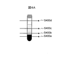
図4Aは、光源200からの光を試験管204に対して照射する位置を駆動装置205によって変化させる様子を示す図である。S400aは血餅層に対する照射位置、S400bは分離剤層に対する照射位置、S400cは血清層に対する照射位置、S400dは空気層に対する照射位置をそれぞれ示す。
<Embodiment 1: Specification of sample component>
FIG. 4A is a diagram showing how the
図4Bは、各試料成分を透過した後の透過光量の波長依存性を示す。波長分光部201を透過する光の波長を変化させながら、受光部202によって試料を透過した光量を計測した結果を模式的に示している。S401aは血餅を、S401bは分離剤を、S401cは血清を、S401dは空気を、それぞれ透過した後の透過光量である。光源200は望ましくは近赤外領域の光を発光し、近赤外領域の光は空気および試験管を透過するのでS401dの透過光量が最も大きく、光源200固有の波長スペクトルに極めて近い形状を示す。分離剤を透過した透過光量S401bが2番目に大きい。分離剤は近赤外領域の光を概ね透過する傾向を示すが、長波長側でその傾向がより顕著となる。血清は近赤外領域の光を概ね吸収する傾向を示し、特に長波長でその傾向は顕著となるので、S401cのような特性となる。血餅は近赤外領域全域において光を強く吸収するので、血餅を透過した透過光量S401aが最も小さい。
FIG. 4B shows the wavelength dependence of the amount of transmitted light after passing through each sample component. The result of measuring the amount of light transmitted through the sample by the
このように光源200からの光が透過する試料成分によって、透過光量や透過光量が特徴的な波長は大きく異なる。透過光量は試料の厚み(本例では試験管204の短手方向)にも依存しており、試料成分を検出する場合には特徴的な波長に着目する必要がある。
As described above, the wavelengths characterized by the amount of transmitted light and the amount of transmitted light differ greatly depending on the sample component through which the light from the
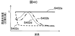
図4Cは、各試料を透過した後の透過光量をそれぞれの最大値で正規化した結果の模式図である。S402aは血餅を、S402bは分離剤を、S402cは血清を、S402dは空気を、それぞれ透過した後の透過光量を各最大値で正規化した結果を示す。透過光量ごとに正規化することにより、各透過光量の波長に対する特性がより顕著になるので、特徴的な波長をより容易に特定することができる。 FIG. 4C is a schematic diagram of the result of normalizing the amount of transmitted light after passing through each sample to the maximum value of each. S402a is a blood clot, S402b is a separating agent, S402c is a serum, and S402d is an air. By normalizing for each transmitted light amount, the characteristics of each transmitted light amount with respect to the wavelength become more remarkable, so that the characteristic wavelength can be specified more easily.
血餅層においては光源200からの光は全波長領域で吸収されるので、S402aにおいて特徴的な波長は存在せず平坦な波長依存特性となる。空気層は光源200からの光をほとんど吸収しないので、S402dは光源200固有のスペクトルに近い形状となる。本実施形態1では近赤外領域の光を放出する発光ダイオードを用いているので、光源200の中心波長付近に1つのピークをもつスペクトルとなる。分離剤の主成分であるオレフィン系樹脂等は、近赤外光を透過するものの、短波長領域においては空気の場合と比較して光を吸収するので、スペクトルのピークは光源200固有の波長から長波長側にシフトし、S402bのような波長依存特性となる。血清の主成分である水は、近赤外領域の長波長側、特に1450nmや1900nm、および両波長の中間波長領域で強く光を吸収するので、スペクトルは光源200固有の波長よりも短波長側にピークをもつ。
In the blood clot layer, the light from the
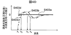
図4Dは、各試料を透過した後の透過光量を最大値で正規化した値に関して一次導関数を算出した結果の模式図である。好ましくは、一次導関数は波長方向に算出される。すなわち波長の増分に対する透過光量の増分を一次導関数とする。S403aは血餅を、S403bは分離剤を、S403cは血清を、S403dは空気を、それぞれ透過した後の透過光量を正規化した値の一次導関数である。一次導関数の値がゼロクロスする波長は、透過光量が極小値もしくは極大値となる波長を意味している。したがってゼロクロス点の波長を特定することにより、各試料成分の特徴的な波長を正確に特定できる。 FIG. 4D is a schematic diagram of the result of calculating the first derivative with respect to the value obtained by normalizing the amount of transmitted light after passing through each sample to the maximum value. Preferably, the first derivative is calculated in the wavelength direction. That is, the increase in the amount of transmitted light with respect to the increase in wavelength is taken as the first derivative. S403a is a blood clot, S403b is a separating agent, S403c is a serum, and S403d is an air, which is a linear derivative of a normalized value of the amount of transmitted light after being transmitted. The wavelength at which the value of the first derivative crosses zero means the wavelength at which the amount of transmitted light becomes a minimum value or a maximum value. Therefore, by specifying the wavelength of the zero cross point, the characteristic wavelength of each sample component can be accurately specified.
図4Cと図4Dによれば、各試料成分を表す特徴波長として、以下を特定することができる。分離剤と空気はそれぞれS402bとS402dに示すように特定の波長λ4とλ3において透過光量がピークとなるので、一次導関数はこれらの波長においてゼロクロスする。したがって一次導関数がこれら波長においてゼロクロスする成分層は、それぞれ血清層と空気層であることが特定できる。血清は短波長領域において透過光量が急峻に減衰する特性を有するので、一次導関数の値が最小である波長λ1から一次導関数の値が0になる波長までの波長領域における一次導関数の変化量(すなわち当該波長領域における二次導関数の値)などを用いて、当該成分層が血清層であることを特定できる。波長領域によらず平坦な特性を有する成分層は血餅層であることが分かる。 According to FIGS. 4C and 4D, the following can be specified as characteristic wavelengths representing each sample component. Since the separated agent and air peak in the amount of transmitted light at specific wavelengths λ4 and λ3 as shown in S402b and S402d, respectively, the first derivative crosses zero at these wavelengths. Therefore, it can be identified that the component layers in which the first derivative crosses zero at these wavelengths are the serum layer and the air layer, respectively. Since serum has the property that the amount of transmitted light is rapidly attenuated in the short wavelength region, the change in the first derivative in the wavelength region from the wavelength λ1 where the value of the first derivative is the minimum to the wavelength where the value of the first derivative becomes 0. It is possible to identify that the component layer is a serum layer by using an amount (that is, a value of a quadratic derivative in the wavelength region) or the like. It can be seen that the component layer having flat characteristics regardless of the wavelength region is a blood clot layer.
以上の説明においては、特徴的な波長成分を特定する便宜上、透過光量の一次導関数の値を用いることとしたが、図4Cから分かるように正規化した透過光量それ自体も特徴的なスペクトル特性を有しているので、これを用いて同様の処理を実施することもできる。例えばS402cにおいて、透過光量が最大となる波長と最小となる波長との間の差分に基づき、透過光量が短波長領域において急峻に減衰しているか否かを特定することができる。 In the above description, for the convenience of specifying the characteristic wavelength component, the value of the first derivative of the transmitted light amount is used, but as can be seen from FIG. 4C, the normalized transmitted light amount itself is also a characteristic spectral characteristic. Therefore, the same processing can be carried out using this. For example, in S402c, it is possible to specify whether or not the transmitted light amount is steeply attenuated in the short wavelength region based on the difference between the wavelength at which the transmitted light amount is maximum and the wavelength at which the transmitted light amount is minimum.
試料の成分が複雑である場合、例えば、脂肪成分が過剰に溶出した血清や、ビーズ、ゲル、ゴムなどの異なる種類の分離剤が含まれている場合には、λ2のような極小値を示す波長を抽出し、これを用いて各試料成分層を特定してもよい。極小値と極大値の区別は、あらかじめ試料成分ごとに把握しておけばよい。 When the components of the sample are complex, for example, when the serum contains excessively eluted fat components or when different types of separating agents such as beads, gels, and rubbers are contained, a minimum value such as λ2 is shown. The wavelength may be extracted and used to identify each sample component layer. The distinction between the minimum value and the maximum value may be grasped in advance for each sample component.
図5は、試験管204にラベル213が貼付されている場合における、照射位置の模式図、および各試料を透過した後の透過光量の波長依存性の模式図である。S500aはラベルと血餅を、S500bはラベルと分離剤を、S500cはラベルと血清を、S500dはラベルと空気を、それぞれ計測した場合の光ビームの模式図である。S501aはラベルと血餅を、S501bはラベルと分離剤を、S501cはラベルと血清を、S501dはラベルと空気を、それぞれ透過した後の透過光量を各最大値で正規化した結果を示す。比較のため図4Cで説明した波長特性を併記した。
FIG. 5 is a schematic diagram of the irradiation position when the
図5に示すように、ラベル213が存在する試験管204の場合であっても、ピーク波長は変化しない。したがって、ラベル213の有無に関わらず試料成分層の位置を検出することができる。
As shown in FIG. 5, the peak wavelength does not change even in the case of the
試験管204の表面にラベル213が貼付されている場合、ラベル213表面で光源200の光が散乱し、もしくはラベル213内部において光が吸収されるので、受光部202において検出される光量は低下する。ラベル213が貼付されていることによる光量低下の主要因は、ラベル213表面における光散乱である。この光散乱により、近赤外領域では波長によらず全波長領域において一定の光量が低下する。すなわち、ラベル213の有無に関わらず、試料成分のみに依拠して、透過光量がピークを示す波長が決まる。したがって図4B~図4Dで説明した手法により、血餅、分離剤、血清、空気の試料成分を特定できる。したがって、ラベル213が存在する場合であっても、試料成分を正確に特定することができる。
When the
図5において、ラベル213は受光部202の方向を向いているが、本実施形態1はラベル213が光源200の方向を向いている場合に適用してもよい。試験管204の全周にわたってラベルが貼付されて目視で中身が確認しがたい場合や、複数枚のラベルが重ねて貼付されている場合であっても、本実施形態1を適用してもよい。その場合には、ラベルを透過させるために高出力のレーザ、もしくは高出力の発光ダイオードを用いてもよいし、発光のタイミングを間欠的なパルス状にすることによって瞬間的に高出力が得られるように光源200を制御してもよい。複数のラベルが貼付されている場合には、光源200のみならず受光部202においてもダイナミックレンジの広い光量の計測が求められる。そこで、受光部202において得られた信号を、対数増幅器を用いて広いダイナミックレンジにて検出してもよいし、動的にゲインを変更できるオートマティックゲインコントロール増幅器を用いてもよい。さらに、上述のパルス発光の場合には、発光周期に同期させて計測を実施することにより、信号対雑音比を向上させてもよい。
In FIG. 5, the
<実施の形態1:まとめ>
本実施形態1に係る生体試料分析装置10は、試験管204を透過した透過光量がピークとなる波長を特定することにより、試験管204が収容している各層の試料成分を特定する。すなわち、複数の波長成分を有する光を光源200が出射し、波長分光部201が特定の波長成分を分離することにより、各層の試料成分を特定することができる。したがって、複数の光源を用いることなく、簡易な光学系構成により各試料成分を正確に特定することができる。
<Embodiment 1: Summary>
The
<実施の形態2>
本発明の実施形態2では、実施形態1で説明した装置構成と原理を前提として、試験管204が収容している各試料成分層間の境界面位置を特定する具体的な手順について説明する。生体試料分析装置10の構成は実施形態1と同様であるので、以下では境界面位置を特定する手順について主に説明する。
<Embodiment 2>
In the second embodiment of the present invention, a specific procedure for specifying the boundary surface position between the layers of each sample component housed in the
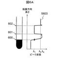
図6Aは、駆動装置205を用いて試験管204の位置を変化させながら取得した、試料透過後の透過光量が最大値となる波長のプロットである。光源200からの光が吸収されて透過光量が検出下限以下となり、ピーク波長が検知できない場合、ピーク波長は光源200に含まれる最も短い波長である1300nmであるものと仮定した。ここでは一般的な生化学免疫分析等で用いられる血液の成分を分離した試料の例を示す。試料は試験管の底から、血餅208/分離剤209/血清210の三層構造になっており、血清の上には空気211の層が存在する。試料の境界面は、血餅と分離剤との間の境界面600、分離剤と血清との間の境界面601、血清と空気との間の境界面602である。特に分析に用いられる血清210の境界面位置を検出することが重要である。ピーク波長は図4Cに示した波形にしたがって、鉛直方向に試験管204を移動させることにより、ピーク波長の高さ依存性S603を取得した。
FIG. 6A is a plot of the wavelength at which the amount of transmitted light after passing through the sample becomes the maximum value, which is obtained while changing the position of the
図4Cで説明したように、空気211におけるピーク波長はλ3、血清210におけるピーク波長はλ1、分離剤209におけるピーク波長はλ4、血餅208におけるピーク波長は存在しない。したがってピーク波長が変化する高さを特定することにより、各試料成分層間の境界面位置を検出することができる。図6中には示してはいないが、試験管204の底より下方の位置においては、試料や試験管等光源からの光を吸収する物体は通常存在しないので、ピーク波長は光源200の中心波長となる。これを利用して試験管204の底を検出することもできる。
As described with reference to FIG. 4C, the peak wavelength in the
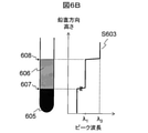
図6Bは、例えば血液凝固分析等で用いられる試料について同様に試料成分層間の境界面位置を特定した結果の例である。試料は、試験管の底から、血球605/血しょう606の二層構造になっており、血しょうの上には空気211の層が存在する。試料の境界面は、血球と血しょうとの間の境界面607、血しょうと空気との間の境界面608、である。図6Aと同じく、ピーク波長は試料成分層に対応して階段状に変化している。したがってこのような試料の場合にも、ピーク波長が変化する高さを抽出することにより、試料成分層間の境界面位置を検出することができる。
FIG. 6B is an example of the result of similarly specifying the boundary surface position between the sample component layers for a sample used in, for example, blood coagulation analysis. The sample has a two-layer structure of
本実施形態2では、試験管204の位置を約1mm単位で移動させながら計測を実施した。ピーク波長が変化する位置と、ノギスによって測定した試料境界面位置との間の誤差は、1mm以内と良好であった。試験管204と光源200との間の相対位置をより精密に変化させることにより、さらに精密に境界面位置を計測してもよい。また、図6Bのような試料において精密に境界面位置が算出できる場合には、血球と血しょうの間に僅かに存在する、バフィーコートと呼ばれる層を検出するために、本発明を用いてもよい。バフィーコート中には、血小板や細胞成分が多く含まれるので、例えば血液凝固分析においてはバフィーコートを除外するニーズがあり、例えば遺伝子検査においてはバフィーコートを含めて試料を分注するニーズがある。本発明によりこれらニーズを実現することができる。
In the second embodiment, the measurement was performed while moving the position of the
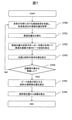
図7は、生体試料分析装置10が試料の境界面位置を抽出する手順を説明するフローチャートである。以下図7の各ステップについて説明する。
FIG. 7 is a flowchart illustrating a procedure in which the
(図7:ステップS700)
光源200は、試料を含む試験管204の側方から光を照射する。受光部202は、試料と波長分光部201を透過した光の透過光量を取得する。コンピュータ203は、波長分光部201が分離する波長を走査させながら各波長における透過光量を取得することにより、近赤外波長領域内の各波長における透過光量を取得する。
(Fig. 7: Step S700)
The
(図7:ステップS701)
コンピュータ203は、走査した波長範囲内における透過光量の最大値を基準として、透過光量を正規化する。
(FIG. 7: Step S701)
The
(図7:ステップS702)
コンピュータ203は、ステップS701において正規化した透過光量の波長方向への一次導関数を算出する。すなわち、波長の増分に対する透過光量の増分を表す関数を求める。コンピュータ203は、求めた一次導関数のゼロクロス点を特定することにより、透過光量が最大となるピーク波長を算出する。さらに、図4Cと図4Dで説明した血清のような特性を有する試料成分については、一次導関数の最大値と最小値、および二次導関数を求めてもよい。
(FIG. 7: Step S702)
The
(図7:ステップS703)
コンピュータ203は、駆動装置205により光源200と試験管204との間の相対位置を変化させる。すなわち、試験管204に対して光を照射する高さ方向の位置を変化させる。好ましくは本ステップにおいて、所望の境界面位置分解能と同程度の分解能で相対位置を移動させる。
(FIG. 7: Step S703)
The
(図7:ステップS704)
好ましくは、試験管204の底と同じ高さに光源200が配置された状態からステップS700を開始し、コンピュータ203は、試験管204の高さに相当する距離だけ相対位置を変化させるまで、S700からS703を繰り返す。試験管204自体の高さに関わらず、試料が存在する位置があらかじめ規定されている場合は、本ステップにおいて必ずしも試験管204の高さ分移動する必要は無く、所定の高さだけ移動した後に本ステップを終了してもよい。
(FIG. 7: Step S704)
Preferably, step S700 is started from the state where the
(図7:ステップS705~S706)
コンピュータ203は、ステップS702の結果にしたがって、試料成分層間の境界面位置を求める(S705)。コンピュータ203は、求めた境界面位置と試験管204のサイズ(例えば内径)を用いて、各試料成分の液量を算出する(S706)。
(FIG. 7: Steps S705 to S706)
The
図7に示した各ステップは、この順番に限るものではない。例えば、S701とS702はS704の次に実施しても構わない。高分解能で境界面位置を算出する場合は、S700とS703を独立に実施する必要があるが、分解能は追求せず高速に境界面位置を算出したいという要求に応えるためには、S700とS703を同時に実施し、S704の後にS701およびS702を実施してもよい。 The steps shown in FIG. 7 are not limited to this order. For example, S701 and S702 may be carried out after S704. When calculating the boundary surface position with high resolution, it is necessary to carry out S700 and S703 independently, but in order to meet the demand for high-speed calculation of the boundary surface position without pursuing resolution, S700 and S703 are used. It may be carried out at the same time, and S701 and S702 may be carried out after S704.
<実施の形態3>
実施形態1~2においては、波長分光部201が分離する波長を走査することにより、各試料成分を特定する手順を説明した。実施形態1~2で説明した手法を用いる場合、波長分光部201が分離する波長を連続的に変化させることになる。図3に示したようなファブリ・ペローフィルタは電圧によりミラー薄膜301の物理的な距離を変更させて透過波長を変化させるので、透過波長が安定するまでに時間を要する。したがって実施形態1~2において、波長領域を連続的に変化させるためには、計測のスループットは犠牲になる。
<Embodiment 3>
In the first and second embodiments, the procedure for specifying each sample component by scanning the wavelengths separated by the wavelength
他方で試料成分の構成があらかじめ分かっており各試料成分層の位置のみを特定する必要がある場合は、必ずしも波長を走査して全ての波長における透過光量を取得する必要はないと考えられる。本発明の実施形態3ではこのことを利用して各試料成分を簡易的に特定する手順を説明する。生体試料分析装置10の構成は実施形態1~2と同様である。
On the other hand, if the composition of the sample components is known in advance and it is necessary to specify only the position of each sample component layer, it is considered that it is not always necessary to scan the wavelengths to obtain the transmitted light amount at all wavelengths. In the third embodiment of the present invention, a procedure for simply specifying each sample component by utilizing this will be described. The configuration of the
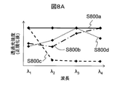
図8Aは、波長分光部201の透過波長をλ1~λ4まで変化させた場合における、透過光量の波長依存性を示す。S800aは血餅を、S800bは分離剤を、S800cは血清を、S800dは空気を、それぞれ透過した後の透過光量を各最大値で正規化した結果を示す。図4Cで説明したように、透過光量がピークとなる波長は試料成分層ごとにそれぞれ異なる。したがって、試料成分の構成と各試料成分の波長特性があらかじめ分かっているのであれば、各試料成分層に対してλ1~λ4それぞれの透過光量を測定し、いずれの波長において透過光量がピークとなるかを判定することにより、各層の試料成分を特定することができる。
FIG. 8A shows the wavelength dependence of the amount of transmitted light when the transmitted wavelength of the wavelength
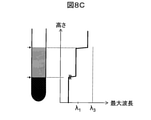
図8Bは、試験管204に血餅208、分離剤209、血清210が含まれた場合において、図8Aで説明した手順にしたがって各試料成分を特定した結果を示す。透過波長を連続的に走査させた図6Aと同様に、透過光量が最大となる波長は、試料成分層間の境界位置に応じてステップ状に変化する。すなわち、透過光量が最大となる波長の変化点を算出することにより、試料層間の境界面位置を検出することができる。
FIG. 8B shows the results of identifying each sample component according to the procedure described in FIG. 8A when the
図8Cは、試験管204に血球605と血しょう606が含まれた場合において、図8Aで説明した手順にしたがって各試料成分を特定した結果を示す。図8Bと同様に、透過光量が最大となる波長の変化点を算出することにより、試料層間の境界面位置を検出することができる。
FIG. 8C shows the results of identifying each sample component according to the procedure described in FIG. 8A when the
図8Aで説明した手順により試料成分層間の境界面位置を特定する場合、各波長は光源200の中心波長周辺から数点程度選択することが望ましく、さらには検出したい試料成分層の層数と同数程度を選択することが好ましい。
When specifying the boundary surface position between the sample component layers by the procedure described with FIG. 8A, it is desirable to select several wavelengths from around the center wavelength of the
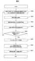
図9は、生体試料分析装置10が試料の境界面位置を抽出する手順を説明するフローチャートである。以下図9の各ステップについて説明する。
FIG. 9 is a flowchart illustrating a procedure in which the
(図9:ステップS900)
本ステップはステップS700と同様である。ただしコンピュータ203は、波長分光部201が分離する波長を、図8Aで説明したように離散的に変化させる点が、ステップS700とは異なる。
(Fig. 9: Step S900)
This step is the same as step S700. However, the
(図9:ステップS901~S902)
S901はステップS701と同様である。コンピュータ203は、正規化した透過光量が最大となる波長方向を特定する(S902)。例えば図8AのS800dにおいては、波長λ1~λ4のうち透過光量が最大となるのはλ3である。
(FIG. 9: Steps S901 to S902)
S901 is the same as step S701. The
(図9:ステップS903~S904)
これらステップはS703~S704と同様である。
(FIG. 9: Steps S903 to S904)
These steps are the same as in S703 to S704.
(図9:ステップS905)
コンピュータ203は、好ましくは、得られた鉛直方向のプロットに対して、フィルタ処理などによってノイズを除去する。これは図8Bにおける血清と空気との間の境界面付近に存在しているようなノイズ成分を取り除き、試料の境界面位置を正確に演算するためである。
(FIG. 9: Step S905)
The
(図9:ステップS906~S907)
これらステップはS705~S706と同様である。
(FIG. 9: Steps S906 to S907)
These steps are the same as in S705 to S706.
<実施の形態3:まとめ>
本実施形態3に係る生体試料分析装置10は、あらかじめ成分構成がわかっている試料に対して、各成分の透過光量がピークとなる波長の光を照射することにより、各層の試料成分を特定する。これにより、波長分光部201が分離する波長成分を走査する必要がなくなるので、試料成分層の境界面位置を、精度よくかつ高速に特定することができる。
<Embodiment 3: Summary>
The
<本発明の変形例について>
本発明は、前述した実施形態に限定されるものではなく、様々な変形例が含まれる。例えば、上記した実施形態は本発明を分かりやすく説明するために詳細に説明したものであり、必ずしも説明した全ての構成を備えるものに限定されるものではない。また、ある実施形態の構成の一部を他の実施形態の構成に置き換えることが可能であり、また、ある実施形態の構成に他の実施形態の構成を加えることも可能である。また、各実施形態の構成の一部について、他の構成の追加・削除・置換をすることが可能である。
<About a modification of the present invention>
The present invention is not limited to the above-described embodiment, and includes various modifications. For example, the above-described embodiment has been described in detail in order to explain the present invention in an easy-to-understand manner, and is not necessarily limited to the one including all the described configurations. Further, it is possible to replace a part of the configuration of one embodiment with the configuration of another embodiment, and it is also possible to add the configuration of another embodiment to the configuration of one embodiment. Further, it is possible to add / delete / replace a part of the configuration of each embodiment with another configuration.
以上の実施形態においては、試料を試験管204に入れた例を説明したが、試験管204に限定されず、他の容器が使用されてもよい。以上の実施形態においては、試験管204と受光部202との間に波長分光部201が配置されているが、試験管204と波長分光部201との位置関係は逆でも構わない。すなわち光源200と受光部202の間に試験管204と波長分光部201が存在すれば、順序は問わない。
In the above embodiment, the example in which the sample is placed in the
以上の実施形態においては、試験管204の位置を移動させることによって、試験管204と光源200との間の相対位置を変化させたが、試験管204は固定しておき、光源200(および波長分光部201と受光部202)の位置を移動させてもよい。
In the above embodiment, the relative position between the
以上の実施形態によって得られた試料成分層間の境界面位置(例えば境界面601や境界面607)は、分注モジュール107が活用してもよい。分注モジュール107は、試験管204から血清や血しょうを一定量吸引し、別の試験管に小分けにする。この工程において、分注プローブが粘性の高い分離剤や血球成分まで挿入されると、プローブが詰まる可能性が高く分析が止まるリスクが高い。そこで、得られた境界面位置情報を元に分注プローブの位置を制御すれば、そのリスクを低減することができる。また一般に、試料は円筒形状の試験管に入っている場合が多い。したがって試料層の境界面位置が分かれば、そこから試料層を円柱等で近似することによって、体積を算出することができる。例えばステップS706においてこの手順を用いることができる。この体積情報を元にすれば、分注モジュール107によって何回分注できるか試算することができる。もし試料量が不足している場合には、優先項目から分析を実施するなどしてもよい。
The
上記の各構成、機能、処理部、処理手段等は、それらの一部又は全部を、例えば集積回路で設計する等によりハードウェアで実現してもよい。また、上記の各構成、機能等は、プロセッサがそれぞれの機能を実現するプログラムを解釈し、実行することによりソフトウェアで実現してもよい。各機能を実現するプログラム、テーブル、ファイル等の情報は、メモリや、ハードディスク、SSD(Solid State Drive)等の記録装置、または、ICカード、SDカード等の記録媒体に置くことができる。また、制御線や情報線は説明上必要と考えられるものを示しており、製品上必ずしも全ての制御線や情報線を示しているとは限らない。実際には殆ど全ての構成が相互に接続されていると考えてもよい。 Each of the above configurations, functions, processing units, processing means, and the like may be realized by hardware, for example, by designing a part or all of them by an integrated circuit. Further, each of the above configurations, functions, and the like may be realized by software by the processor interpreting and executing a program that realizes each function. Information such as programs, tables, and files that realize each function can be placed in a memory, a hard disk, a recording device such as an SSD (Solid State Drive), or a recording medium such as an IC card or an SD card. In addition, the control lines and information lines indicate those that are considered necessary for explanation, and do not necessarily indicate all the control lines and information lines in the product. In practice, it can be considered that almost all configurations are interconnected.
100…前処理システム
101…搬送ライン
102…投入モジュール
103…遠心分離モジュール
104…検出装置
105…開栓モジュール
106…ラベラ
107…分注モジュール
108…閉栓モジュール
109…仕分けモジュール
110…収納モジュール
111…制御用PC
112…自動分析装置
200…光源
201…波長分光部
202…受光部
203…コンピュータ
204…試験管
205…駆動装置
206…把持装置
207…表示機
208…血餅
209…分離剤
210…血清
211…空気
212…キャップ
213…ラベル
300…レンズ
301…ミラー薄膜
302…中間層
303…電圧制御装置
100 ...
112 ...
Claims (11)
前記試料から分離された1以上の前記試料成分を層状に収容した容器に対して光を照射する光源、
前記光が有する波長成分を分離する分光部、
前記試料、前記容器、および前記分光部を通過した前記波長成分の光強度を計測するセンサ、
前記分光部が前記光から分離する波長成分を変更する制御装置、
前記センサが計測した前記波長成分の光強度を用いて、前記試料内に含まれる前記試料成分を特定する、演算装置、
を備え、
前記分光部は、ギャップを介して2つのミラー薄膜を配置することにより、光の干渉を利用して、前記ギャップに応じて特定波長の光のみを透過させるように構成されており、 前記制御装置は、前記ギャップを制御することにより、特定波長の前記波長成分のみを透過させるように前記分光部を制御し、
前記試料内に含まれる第1試料成分は、前記光が有する波長成分のうち第1波長において、前記センサが計測した光強度が最大となる特性を有しており、
前記試料内に含まれる前記第1試料成分とは異なる第2試料成分は、前記光が有する波長成分のうち前記第1波長よりも大きい第2波長において、前記センサが計測した光強度が最大となる特性を有しており、
前記光源は、前記第1波長よりも小さい第3波長から前記第2波長よりも大きい第4波長までにわたる複数の波長成分を有する前記光を出射するように構成されており、
前記分光部は、前記光源が出射する前記光から分離する波長成分を前記第3波長から前記第4波長にわたって走査することにより、前記第1波長と前記第2波長を包含する波長領域にわたる前記光が前記センサに対して照射されるようにし、
前記演算装置は、前記第3波長から前記第4波長にわたる波長範囲のなかで前記センサが計測した光強度が最大となる波長を前記層ごとに特定することにより、前記容器が収容している各前記試料成分を特定する
ことを特徴とする分析装置。 It is an analyzer that analyzes the sample components contained in the sample.
A light source that irradiates a container containing one or more of the sample components separated from the sample in a layered manner with light.
A spectroscopic unit that separates the wavelength component of the light,
A sensor that measures the light intensity of the wavelength component that has passed through the sample, the container, and the spectroscopic unit.
A control device that changes the wavelength component that the spectroscopic unit separates from the light.
An arithmetic unit that identifies the sample component contained in the sample by using the light intensity of the wavelength component measured by the sensor.
Equipped with
The spectroscopic unit is configured to transmit only light of a specific wavelength according to the gap by using the interference of light by arranging two mirror thin films through the gap, and the control device. Controls the spectroscopic unit so as to transmit only the wavelength component of a specific wavelength by controlling the gap.
The first sample component contained in the sample has a characteristic that the light intensity measured by the sensor is maximized at the first wavelength among the wavelength components of the light.
The second sample component contained in the sample, which is different from the first sample component, has the maximum light intensity measured by the sensor at the second wavelength, which is larger than the first wavelength among the wavelength components of the light. Has the characteristics of
The light source is configured to emit the light having a plurality of wavelength components ranging from a third wavelength smaller than the first wavelength to a fourth wavelength larger than the second wavelength.
The spectroscopic unit scans the wavelength component separated from the light emitted by the light source from the third wavelength to the fourth wavelength, thereby causing the light to cover a wavelength region including the first wavelength and the second wavelength. Is radiated to the sensor.
Each of the arithmetic units housed in the container by specifying the wavelength at which the light intensity measured by the sensor is maximum in the wavelength range from the third wavelength to the fourth wavelength for each layer. An analyzer characterized by identifying the sample component.
前記演算装置は、前記センサが計測した光強度が波長の増分に対して変化する変化量を求めることにより、波長に対する前記光強度の関数の一次導関数を算出し、
前記演算装置は、前記波長領域内において前記一次導関数の値が0になる波長を特定することにより、前記試料成分を特定する
ことを特徴とする請求項1記載の分析装置。 The sample component has a characteristic that the light intensity of the light transmitted through the sample component has an extreme value at a specific wavelength within a predetermined wavelength region.
The arithmetic unit calculates a linear derivative of the function of the light intensity with respect to the wavelength by obtaining the amount of change in which the light intensity measured by the sensor changes with respect to the increment of the wavelength.
The analyzer according to claim 1, wherein the arithmetic unit specifies the sample component by specifying a wavelength in which the value of the first derivative becomes 0 in the wavelength region.
前記演算装置は、前記センサが計測した光強度が波長の増分に対して変化する変化量を求めることにより、波長に対する前記光強度の関数の一次導関数を算出し、
前記演算装置は、前記一次導関数が最大値をとるときの波長と前記一次導関数が最小値をとるときの波長との間の差分、および前記最大値と前記最小値との間の差分にしたがって、前記一次導関数の特徴を特定することにより、前記試料成分を特定する
ことを特徴とする請求項1記載の分析装置。 The sample component has a characteristic that the light intensity of the light transmitted through the sample component has an extreme value at a specific wavelength within a predetermined wavelength region.
The arithmetic unit calculates a linear derivative of the function of the light intensity with respect to the wavelength by obtaining the amount of change in which the light intensity measured by the sensor changes with respect to the increment of the wavelength.
The arithmetic unit determines the difference between the wavelength when the first derivative takes the maximum value and the wavelength when the first derivative takes the minimum value, and the difference between the maximum value and the minimum value. Therefore, the analyzer according to claim 1, wherein the sample component is specified by specifying the characteristics of the first derivative.
前記分光部は、各前記試料成分に対応する各前記特定波長をそれぞれ分離し、
前記演算装置は、前記センサの計測結果を各前記試料成分に対応する各前記特定波長についてそれぞれ取得することにより、各前記層について前記特定波長を特定し、
前記演算装置は、各前記層がその特定した波長に対応する前記試料成分であることを特定する
ことを特徴とする請求項1記載の分析装置。 Each of the sample components has a characteristic that the light intensity of the light transmitted through the sample component has a maximum value at different specific wavelengths within a predetermined wavelength region.
The spectroscopic unit separates each of the specific wavelengths corresponding to each of the sample components.
The arithmetic unit identifies the specific wavelength for each layer by acquiring the measurement result of the sensor for each specific wavelength corresponding to each sample component.
The analyzer according to claim 1, wherein the arithmetic unit identifies that each layer is the sample component corresponding to the specified wavelength.
ことを特徴とする請求項1記載の分析装置。 The arithmetic unit is characterized in that after normalizing the light intensity measured by the sensor, the sample component contained in the container is specified by specifying the wavelength at which the light intensity is maximized. The analyzer according to claim 1.
前記演算装置は、前記駆動装置によって前記照射位置を変化させながら前記試料成分を特定することにより、前記試料内に含まれる第1試料成分と第2試料成分との間の境界位置を特定する
ことを特徴とする請求項1記載の分析装置。 The analyzer further comprises a drive device that changes the irradiation position on the container to which the light is irradiated.
The arithmetic unit specifies the boundary position between the first sample component and the second sample component contained in the sample by specifying the sample component while changing the irradiation position by the driving device. The analyzer according to claim 1.
ことを特徴とする請求項6記載の分析装置。 The arithmetic unit uses the inner diameter of the container and the boundary position to obtain the volume of the first sample component contained in the container and the volume of the second sample component contained in the container. The analyzer according to claim 6, wherein at least one of them is calculated.
前記演算装置は、前記境界位置として、血餅と分離剤との間の境界面、前記血清と前記分離剤との間の境界面、前記血清の上側液面、血球と前記血しょうとの間の境界面、および前記血しょうの上側液面、のうち少なくともいずれかを特定する
ことを特徴とする請求項6記載の分析装置。 The sample contains serum or plasma after centrifugation of blood as the sample component.
The arithmetic unit has, as the boundary position, the boundary surface between the blood clot and the separating agent, the boundary surface between the serum and the separating agent, the upper liquid surface of the serum, and between the blood cell and the plasma. The analyzer according to claim 6, wherein at least one of the boundary surface of the blood plasma and the upper liquid level of the plasma is specified.
ことを特徴とする請求項8記載の分析装置。 The analyzer according to claim 8, wherein the light source irradiates the light having a near infrared wavelength.
ことを特徴とする請求項8記載の分析装置。 The analyzer according to claim 8, wherein the spectroscopic unit has a wavelength resolution shorter than a full width at half maximum of 20 nm.
ことを特徴とする請求項1記載の分析装置。 The analyzer according to claim 1, further comprising an automatic analysis unit for quantitatively analyzing the sample components.
Priority Applications (2)
| Application Number | Priority Date | Filing Date | Title |
|---|---|---|---|
| JP2018106834A JP6999500B2 (en) | 2018-06-04 | 2018-06-04 | Analysis equipment |
| PCT/JP2019/009851 WO2019235015A1 (en) | 2018-06-04 | 2019-03-12 | Analyzer |
Applications Claiming Priority (1)
| Application Number | Priority Date | Filing Date | Title |
|---|---|---|---|
| JP2018106834A JP6999500B2 (en) | 2018-06-04 | 2018-06-04 | Analysis equipment |
Publications (3)
| Publication Number | Publication Date |
|---|---|
| JP2019211303A JP2019211303A (en) | 2019-12-12 |
| JP2019211303A5 JP2019211303A5 (en) | 2021-02-04 |
| JP6999500B2 true JP6999500B2 (en) | 2022-02-10 |
Family
ID=68769330
Family Applications (1)
| Application Number | Title | Priority Date | Filing Date |
|---|---|---|---|
| JP2018106834A Active JP6999500B2 (en) | 2018-06-04 | 2018-06-04 | Analysis equipment |
Country Status (2)
| Country | Link |
|---|---|
| JP (1) | JP6999500B2 (en) |
| WO (1) | WO2019235015A1 (en) |
Families Citing this family (3)
| Publication number | Priority date | Publication date | Assignee | Title |
|---|---|---|---|---|
| JP7075213B2 (en) * | 2017-12-28 | 2022-05-25 | シスメックス株式会社 | Specimen measurement method and sample measurement device |
| JP2022142191A (en) * | 2021-03-16 | 2022-09-30 | パナソニックIpマネジメント株式会社 | Interface detection sensor |
| JP2022149718A (en) * | 2021-03-25 | 2022-10-07 | パナソニックIpマネジメント株式会社 | Interface detection sensor and interface detection method |
Citations (8)
| Publication number | Priority date | Publication date | Assignee | Title |
|---|---|---|---|---|
| JP2003014641A (en) | 2001-07-04 | 2003-01-15 | Yokogawa Electric Corp | Infrared analyzer |
| JP2005502877A (en) | 2001-09-12 | 2005-01-27 | テカン・トレーディング・アクチェンゲゼルシャフト | System, method and computer program for measuring optical transmission and for evaluating a determined measurement variable |
| JP2005516212A (en) | 2002-01-30 | 2005-06-02 | ベックマン コールター インコーポレイテッド | Sample layer surface detection system |
| JP2006010453A (en) | 2004-06-24 | 2006-01-12 | Aloka Co Ltd | Interface detector, volume measuring instrument, and interface detecting method |
| JP2007255918A (en) | 2006-03-20 | 2007-10-04 | Kyokko Denki Kk | Spectroscopic analyzer |
| JP2016061585A (en) | 2014-09-16 | 2016-04-25 | ジーニアルライト株式会社 | Blood coagulation detection device, blood coagulation detection method, and blood coagulation detection program |
| JP2016090250A (en) | 2014-10-30 | 2016-05-23 | セイコーエプソン株式会社 | Spectrometer and storage case |
| US20170138790A1 (en) | 2014-06-27 | 2017-05-18 | Spectral Engines Oy | A method for determining the spectral scale of a spectrometer and apparatus |
Family Cites Families (5)
| Publication number | Priority date | Publication date | Assignee | Title |
|---|---|---|---|---|
| JPH02195261A (en) * | 1989-01-25 | 1990-08-01 | Shimadzu Corp | Apparatus for sampling blood serum |
| JP2004140606A (en) * | 2002-10-17 | 2004-05-13 | Sharp Corp | Mobile notification apparatus, device information management apparatus, communication system, and mobile notification method |
| JP4160493B2 (en) * | 2003-11-25 | 2008-10-01 | 株式会社エヌ・ティ・ティ・ドコモ | Packet communication monitoring apparatus and packet communication monitoring method |
| JP6033021B2 (en) * | 2012-09-24 | 2016-11-30 | 三菱スペース・ソフトウエア株式会社 | Unauthorized communication detection device, cyber attack detection system, computer program, and unauthorized communication detection method |
| WO2016027447A1 (en) * | 2014-08-19 | 2016-02-25 | 日本電気株式会社 | Communication device, communication system and communication method |
-
2018
- 2018-06-04 JP JP2018106834A patent/JP6999500B2/en active Active
-
2019
- 2019-03-12 WO PCT/JP2019/009851 patent/WO2019235015A1/en active Application Filing
Patent Citations (8)
| Publication number | Priority date | Publication date | Assignee | Title |
|---|---|---|---|---|
| JP2003014641A (en) | 2001-07-04 | 2003-01-15 | Yokogawa Electric Corp | Infrared analyzer |
| JP2005502877A (en) | 2001-09-12 | 2005-01-27 | テカン・トレーディング・アクチェンゲゼルシャフト | System, method and computer program for measuring optical transmission and for evaluating a determined measurement variable |
| JP2005516212A (en) | 2002-01-30 | 2005-06-02 | ベックマン コールター インコーポレイテッド | Sample layer surface detection system |
| JP2006010453A (en) | 2004-06-24 | 2006-01-12 | Aloka Co Ltd | Interface detector, volume measuring instrument, and interface detecting method |
| JP2007255918A (en) | 2006-03-20 | 2007-10-04 | Kyokko Denki Kk | Spectroscopic analyzer |
| US20170138790A1 (en) | 2014-06-27 | 2017-05-18 | Spectral Engines Oy | A method for determining the spectral scale of a spectrometer and apparatus |
| JP2016061585A (en) | 2014-09-16 | 2016-04-25 | ジーニアルライト株式会社 | Blood coagulation detection device, blood coagulation detection method, and blood coagulation detection program |
| JP2016090250A (en) | 2014-10-30 | 2016-05-23 | セイコーエプソン株式会社 | Spectrometer and storage case |
Also Published As
| Publication number | Publication date |
|---|---|
| WO2019235015A1 (en) | 2019-12-12 |
| JP2019211303A (en) | 2019-12-12 |
Similar Documents
| Publication | Publication Date | Title |
|---|---|---|
| US6195158B1 (en) | Apparatus and method for rapid spectrophotometric pre-test screen of specimen for a blood analyzer | |
| JP6005683B2 (en) | Method and apparatus for determining interfering substances and physical dimensions in liquid samples and containers analyzed by a clinical analyzer | |
| EP2775292B1 (en) | Blood coagulation analyzer and blood coagulation analyzing method | |
| JP6592401B2 (en) | Sample liquid level position measuring apparatus and sample liquid level position measuring method | |
| JP6999500B2 (en) | Analysis equipment | |
| US9851301B2 (en) | Method and device for recognizing a mixed or unmixed state of a sample | |
| EP2016390B1 (en) | A method and a system for quantitative hemoglobin determination | |
| JP3017920B2 (en) | Analytical methods for clinically relevant liquids and suspensions | |
| JP3524419B2 (en) | Absorbance measurement device | |
| US20190072484A1 (en) | Tumor cell detection method and tumor cell detection device | |
| US6522398B2 (en) | Apparatus for measuring hematocrit | |
| WO2008151159A2 (en) | Through-container optical evaluation system | |
| EP2784480A2 (en) | Blood cell analyzer and blood cell analyzing method | |
| EP2466292B1 (en) | System for performing scattering and absorbance assays | |
| JP2008008794A (en) | Analyzing device | |
| JPH10510362A (en) | Equipment for analyzing blood and other samples | |
| JP7057820B2 (en) | Specimen evaluation method and sample evaluation device using hyperspectral imaging | |
| CN112955742A (en) | Blood sample analysis method and blood coagulation analyzer | |
| JP2008026036A (en) | Inclusion measuring device | |
| US20230102813A1 (en) | Open-loop/closed-loop process control on the basis of a spectroscopic determination of undetermined substance concentrations | |
| JP6328530B2 (en) | Blood coagulation detection apparatus, blood coagulation detection method, and blood coagulation detection program | |
| CN115244382A (en) | Sample analysis method and device | |
| JP7060723B2 (en) | Specimen processing system | |
| US20230143882A1 (en) | Systems and method for measuring pathogens and biomarkers in fluids | |
| CN116242805B (en) | Laser detection method, laser detection device, and computer storage medium |
Legal Events
| Date | Code | Title | Description |
|---|---|---|---|
| A521 | Request for written amendment filed |
Free format text: JAPANESE INTERMEDIATE CODE: A523 Effective date: 20201215 |
|
| A621 | Written request for application examination |
Free format text: JAPANESE INTERMEDIATE CODE: A621 Effective date: 20201215 |
|
| A131 | Notification of reasons for refusal |
Free format text: JAPANESE INTERMEDIATE CODE: A131 Effective date: 20210713 |
|
| A521 | Request for written amendment filed |
Free format text: JAPANESE INTERMEDIATE CODE: A523 Effective date: 20210816 |
|
| TRDD | Decision of grant or rejection written | ||
| A01 | Written decision to grant a patent or to grant a registration (utility model) |
Free format text: JAPANESE INTERMEDIATE CODE: A01 Effective date: 20211207 |
|
| A61 | First payment of annual fees (during grant procedure) |
Free format text: JAPANESE INTERMEDIATE CODE: A61 Effective date: 20211222 |
|
| R150 | Certificate of patent or registration of utility model |
Ref document number: 6999500 Country of ref document: JP Free format text: JAPANESE INTERMEDIATE CODE: R150 |