JP6996442B2 - Vehicle wiper - Google Patents

Vehicle wiper Download PDF

Info

Publication number
JP6996442B2
JP6996442B2 JP2018134334A JP2018134334A JP6996442B2 JP 6996442 B2 JP6996442 B2 JP 6996442B2 JP 2018134334 A JP2018134334 A JP 2018134334A JP 2018134334 A JP2018134334 A JP 2018134334A JP 6996442 B2 JP6996442 B2 JP 6996442B2
Authority
JP
Japan
Prior art keywords
clip
pair
longitudinal direction
wiper
posture
Prior art date
Legal status (The legal status is an assumption and is not a legal conclusion. Google has not performed a legal analysis and makes no representation as to the accuracy of the status listed.)
Active
Application number
JP2018134334A
Other languages
Japanese (ja)
Other versions
JP2020011581A (en
Inventor
啓介 金澤
Current Assignee (The listed assignees may be inaccurate. Google has not performed a legal analysis and makes no representation or warranty as to the accuracy of the list.)
Denso Corp
Original Assignee
Denso Corp
Priority date (The priority date is an assumption and is not a legal conclusion. Google has not performed a legal analysis and makes no representation as to the accuracy of the date listed.)
Filing date
Publication date
Application filed by Denso Corp filed Critical Denso Corp
Priority to JP2018134334A priority Critical patent/JP6996442B2/en
Publication of JP2020011581A publication Critical patent/JP2020011581A/en
Application granted granted Critical
Publication of JP6996442B2 publication Critical patent/JP6996442B2/en
Active legal-status Critical Current
Anticipated expiration legal-status Critical

Links

Images

Description

本発明は、車両用ワイパに関する。 The present invention relates to a vehicle wiper.

下記特許文献1に記載された車両用ワイパでは、ワイパブレードの長手方向中央部に連結レバー(ホルダ本体)が設けられており、当該連結レバーには、クリップの長手方向一端部が回動可能に連結されている。このクリップは、ワイパアームの先端部に設けられた両側被覆壁(一対の対向壁)の間に位置される。そして、この位置から、クリップがワイパアームの先端部に対して相対的にワイパアームの基端側へ移動されると、クリップに形成された一対の係合凸部が、一対の両側被覆壁に形成された一対の係合凹部に嵌合すると共に、クリップに形成された弾性突起が、ワイパアームの先端部に形成された係止孔に嵌合する。これにより、ワイパアームの先端部にクリップが係止され、ワイパアームの先端部に対するワイパブレードの連結状態となる。なお、下記特許文献2には、上記同様の技術が開示されている。 In the vehicle wiper described in Patent Document 1 below, a connecting lever (holder body) is provided at the center of the wiper blade in the longitudinal direction, and one end of the clip in the longitudinal direction of the connecting lever can be rotated. It is connected. This clip is located between both side covering walls (a pair of facing walls) provided at the tip of the wiper arm. Then, when the clip is moved from this position to the base end side of the wiper arm relative to the tip end portion of the wiper arm, a pair of engaging protrusions formed on the clip are formed on the pair of both side covering walls. Along with fitting into the pair of engaging recesses, the elastic protrusion formed on the clip fits into the locking hole formed at the tip of the wiper arm. As a result, the clip is locked to the tip of the wiper arm, and the wiper blade is connected to the tip of the wiper arm. The following Patent Document 2 discloses the same technique as described above.

特許第6081116号公報Japanese Patent No. 6081116 特表2007-524543号公報Special Table 2007-524543

しかしながら、上記の先行技術では、ワイパアームの係止孔に対するクリップの弾性突起の嵌合状態が解除されると、ワイパアームの先端部に対するクリップの係止が解除され、ワイパブレードがワイパアームから取り外し可能となる。このため、上記の係止が何らかの原因で意図せずに解除されると、ワイパブレードがワイパアームから外れる可能性があり、これを防止する観点で改善の余地がある。 However, in the above prior art, when the elastic projection of the clip is released from the locking hole of the wiper arm, the clip is released from the locking to the tip of the wiper arm, and the wiper blade can be removed from the wiper arm. .. Therefore, if the above-mentioned locking is unintentionally released for some reason, the wiper blade may come off from the wiper arm, and there is room for improvement from the viewpoint of preventing this.

本発明は上記事実を考慮し、ワイパアームの先端部に対するクリップの係止が意図せずに解除された場合でも、ワイパブレードがワイパアームから外れることを防止できる車両用ワイパを提供することを目的とする。 In view of the above facts, it is an object of the present invention to provide a vehicle wiper capable of preventing the wiper blade from coming off the wiper arm even when the clip is unintentionally released from the tip of the wiper arm. ..

本発明の第1の態様の車両用ワイパは、払拭面を払拭するためのブレードラバーを有し、長手方向中央部にホルダ本体が設けられたワイパブレードと、前記ワイパブレードの長手方向を長手とし、前記ホルダ本体を挟んで払拭方向に対向する一対の側壁を有し、前記一対の側壁の長手方向一端部が前記ホルダ本体に対して払拭方向に延びる軸線回りに回動可能に連結されたクリップと、払拭方向に対向する一対の対向壁が先端部に形成され、前記一対の対向壁間に前記クリップが配置されて前記先端部に前記クリップが係止されるワイパアームと、前記ホルダ本体に形成され、前記クリップの前記ホルダ本体に対する第1の姿勢において前記一対の側壁の長手方向他端部と第1の間隔を有して前記ワイパブレードの長手方向に対向する抜止壁部と、前記一対の対向壁の内側面に形成され、前記クリップの前記第1の姿勢において前記第1の間隔よりも小さな寸法を有する一対の突起と、を備え、前記クリップの前記第1の姿勢から前記軸線周りに回動された第2の姿勢における前記一対の側壁の長手方向他端部と前記抜止壁部との間の第2の間隔は、前記一対の突起の前記寸法よりも小さく設定されている。 The vehicle wiper according to the first aspect of the present invention has a blade rubber for wiping the wiping surface, and has a wiper blade provided with a holder body at the center in the longitudinal direction and a longitudinal direction of the wiper blade. A clip having a pair of side walls facing each other in the wiping direction with the holder body sandwiched therein, and one end of the pair of side walls in the longitudinal direction rotatably connected around an axis extending in the wiping direction with respect to the holder body. A pair of facing walls facing each other in the wiping direction are formed at the tip portion, and the clip is arranged between the pair of facing walls and the clip is locked to the tip portion. Then, in the first posture of the clip with respect to the holder body, the retaining wall portion facing the wiper blade in the longitudinal direction having a first distance from the other end in the longitudinal direction of the pair of side walls, and the pair of retaining walls. It comprises a pair of protrusions formed on the inner surface of the facing wall and having a size smaller than the first spacing in the first posture of the clip, from the first posture of the clip to the axis. The second distance between the other end of the pair of side walls in the longitudinal direction and the retaining wall portion in the rotated second posture is set to be smaller than the dimension of the pair of protrusions.

第1の態様の車両用ワイパでは、払拭面を払拭するためのブレードラバーを有するワイパブレードの長手方向中央部には、ホルダ本体が設けられている。このホルダ本体には、クリップが回動可能に連結されている。このクリップは、ワイパブレードの長手方向を長手とし、ホルダ本体を挟んで払拭方向に対向する一対の側壁を有しており、一対の側壁の長手方向一端部がホルダ本体に対して払拭方向に延びる軸線回りに回動可能に連結されている。また、ワイパアームの先端部には、払拭方向に対向する一対の対向壁が形成されている。そして、上記のクリップが一対の対向壁間に配置されてワイパアームの先端部に係止される。これにより、ワイパブレードがクリップを介してワイパアームの先端部に連結される。 In the vehicle wiper of the first aspect, a holder main body is provided at the central portion in the longitudinal direction of the wiper blade having the blade rubber for wiping the wiping surface. A clip is rotatably connected to the holder body. This clip has a pair of side walls that face each other in the wiping direction with the holder body interposed therebetween in the longitudinal direction of the wiper blade, and one end of the pair of side walls in the longitudinal direction extends in the wiping direction with respect to the holder body. It is rotatably connected around the axis. Further, a pair of facing walls facing each other in the wiping direction are formed at the tip of the wiper arm. Then, the above-mentioned clip is arranged between the pair of facing walls and locked to the tip of the wiper arm. As a result, the wiper blade is connected to the tip of the wiper arm via the clip.

上記のホルダ本体には、クリップのホルダ本体に対する第1の姿勢において、上記一対の側壁の長手方向他端部と第1の間隔を有してワイパブレードの長手方向に対向する抜止壁部が形成されている。また、ワイパアームが有する一対の対向壁の内側面には、上記第1の間隔よりも小さな寸法を有する一対の突起が形成されている。このため、ワイパアームの一対の対向壁間にクリップを配置させる際には、クリップを上記第1の姿勢とすることにより、一対の突起が一対の側壁の長手方向他端部と抜止壁部との間を通過可能となる。 The holder body is formed with a retaining wall portion facing the wiper blade in the longitudinal direction with a first distance from the other end in the longitudinal direction of the pair of side walls in the first posture of the clip with respect to the holder body. Has been done. Further, on the inner surface of the pair of facing walls of the wiper arm, a pair of protrusions having a dimension smaller than that of the first spacing is formed. Therefore, when arranging the clip between the pair of facing walls of the wiper arm, by setting the clip in the first posture, the pair of protrusions form the other end of the pair of side walls in the longitudinal direction and the retaining wall portion. It becomes possible to pass between.

一方、クリップが上記第1の姿勢から上記軸線周りに回動されて第2の姿勢とされた状態では、一対の側壁の長手方向他端部と抜止壁部との間の第2の間隔が、一対の突起の上記寸法よりも小さくなる。このため、ワイパアームの先端部に対するクリップの係止が解除された場合、クリップが第2の姿勢となることで、一対の突起が一対の側壁の長手方向他端部と抜止壁部との間を通過不能となり、クリップが一対の対向壁間から抜け出せなくなる。このように構成されているので、ワイパアームの先端部に対するクリップの係止が意図せずに解除された場合でも、ワイパブレードがワイパアームから外れる(ワイパブレードとワイパアームが分離してしまう)ことを防止できる。 On the other hand, in the state where the clip is rotated from the first posture to the second posture in the second posture, the second distance between the other end in the longitudinal direction of the pair of side walls and the retaining wall portion is set. , Smaller than the above dimensions of the pair of protrusions. Therefore, when the clip is released from the lock on the tip of the wiper arm, the clip is in the second posture, so that the pair of protrusions can be placed between the other end of the side wall in the longitudinal direction and the retaining wall. It becomes impassable and the clip cannot escape between the pair of facing walls. With this configuration, even if the clip is unintentionally released from the tip of the wiper arm, it is possible to prevent the wiper blade from coming off the wiper arm (the wiper blade and the wiper arm are separated). ..

本発明の第2の態様の車両用ワイパは、第1の態様において、前記クリップを前記第1の姿勢から前記第2の姿勢に向けて付勢する付勢部を備えている。 The vehicle wiper of the second aspect of the present invention includes an urging portion that urges the clip from the first posture to the second posture in the first aspect.

第2の態様の車両用ワイパでは、クリップが付勢部によって第1の姿勢から第2の姿勢(即ち一対の側壁の長手方向他端部と抜止壁部との間の第2の間隔が、一対の突起の寸法よりも小さくなる姿勢)に向けて付勢されている。これにより、ワイパアームの先端部に対するクリップの係止が解除された場合に、クリップが意図せずに第2の姿勢から第1の姿勢になることを防止できる。 In the vehicle wiper of the second aspect, the clip has a second position from the first posture to the second posture (that is, the second distance between the other end in the longitudinal direction of the pair of side walls and the retaining wall portion) by the urging portion. It is urged toward a posture that is smaller than the size of the pair of protrusions). This makes it possible to prevent the clip from unintentionally changing from the second posture to the first posture when the clip is released from being locked to the tip of the wiper arm.

本発明の第3の態様の車両用ワイパは、第2の態様において、前記付勢部は、前記クリップと一体に形成されている。 In the second aspect of the vehicle wiper according to the third aspect of the present invention, the urging portion is integrally formed with the clip.

本発明の第3の態様の車両用ワイパによれば、クリップと一体に形成された付勢部によって、クリップがホルダ本体に対して上側へ付勢されている。このため、クリップとは別体の付勢部が設けられる構成と比較して、構成を簡素化することができる。 According to the vehicle wiper of the third aspect of the present invention, the clip is urged upward with respect to the holder body by the urging portion integrally formed with the clip. Therefore, the configuration can be simplified as compared with the configuration in which the urging portion separate from the clip is provided.

本発明の第4の態様の車両用ワイパは、第2又は第3の態様において、前記クリップの前記第1の姿勢における前記一対の側壁の長手方向他端部と前記抜止壁部との間には、前記一対の突起が通過可能な通路が形成され、該通路は、上側の部位が下側の部位よりも前記一対の側壁の長手方向一端部側に位置するようにクランク状に曲がった形状となる。 The vehicle wiper according to the fourth aspect of the present invention has, in the second or third aspect, between the other end in the longitudinal direction of the pair of side walls in the first posture of the clip and the retaining wall portion. Is a shape in which a passage through which the pair of protrusions can pass is formed, and the upper portion is bent like a crank so that the upper portion is located closer to one end portion in the longitudinal direction of the pair of side walls than the lower portion. Will be.

第4の態様の車両用ワイパでは、クリップの第1の姿勢において、一対の側壁の長手方向他端部と抜止壁部との間には、一対の突起が通過可能な通路が形成される。この通路は、上側の部位が下側の部位よりも一対の側壁の長手方向一端部側に位置するようにクランク状に曲がった形状となる。このように構成されているので、クリップが有する一対の側壁の長手方向他端部には、それぞれ段部が形成される。このため、ワイパアームの一対の対向壁間にクリップを配置させる際に、一対の突起を上記各段部に宛がうことにより、クリップを付勢部の付勢力に抗して第2の姿勢から第1の姿勢へと回動させることができる。これにより、ワイパアームの先端部に対するクリップの組付け作業が容易になる。 In the vehicle wiper of the fourth aspect, in the first posture of the clip, a passage through which a pair of protrusions can pass is formed between the other end in the longitudinal direction of the pair of side walls and the retaining wall portion. This passage has a shape bent like a crank so that the upper portion is located on the one end side in the longitudinal direction of the pair of side walls with respect to the lower portion. Since it is configured in this way, a step portion is formed at the other end of the pair of side walls of the clip in the longitudinal direction. Therefore, when arranging the clip between the pair of facing walls of the wiper arm, by applying the pair of protrusions to each of the above-mentioned steps, the clip is moved from the second posture against the urging force of the urging portion. It can be rotated to the first posture. This facilitates the work of assembling the clip to the tip of the wiper arm.

本発明の第5の態様の車両用ワイパは、第1~第4の態様の何れか1つの態様において、前記一対の抜止壁部は、前記一対の突起が前記ワイパアームの基端側に向けて接触したとき、前記一対の突起に対して下向きの分力を付与する分力付与面を有する。 The vehicle wiper according to the fifth aspect of the present invention has, in any one of the first to fourth aspects, the pair of retaining wall portions having the pair of protrusions directed toward the base end side of the wiper arm. It has a component force applying surface that applies a downward component force to the pair of protrusions when in contact with each other.

第5の態様の車両用ワイパによれば、ブレードラバーによる払拭面の払拭時に、ワイパアームの先端部に対するクリップの係止が解除された場合、抜止壁部が有する分力付与面に対して一対の突起がワイパアームの基端側向きに接触する。これにより、ワイパアームの一対の突起には、下向きの分力、即ちワイパアームの先端部がクリップから外れる向きとは逆向きの分力が作用する。これにより、ワイパブレードとワイパアームとが外れる(分離されてしまう)ことを一層効果的に防止できる。 According to the vehicle wiper of the fifth aspect, when the clip is released from the lock on the tip of the wiper arm when the wiper surface is wiped by the blade rubber, a pair of force-applied surfaces of the retaining wall portion. The protrusion contacts the wiper arm toward the base end. As a result, a downward component force acts on the pair of protrusions of the wiper arm, that is, a component force in the direction opposite to the direction in which the tip portion of the wiper arm comes off the clip. As a result, it is possible to more effectively prevent the wiper blade and the wiper arm from coming off (separated).

一実施の形態におけるワイパの斜視図。The perspective view of the wiper in one Embodiment. 一実施の形態におけるワイパの一部分解斜視図。Partially disassembled perspective view of the wiper in one embodiment. 一実施の形態におけるワイパの一部断面図。Partial sectional view of the wiper in one embodiment. 一実施の形態におけるワイパの一部断面図。Partial sectional view of the wiper in one embodiment. (a),(b)は一実施の形態における連結レバーの斜視図。(A) and (b) are perspective views of the connecting lever in one embodiment. 一実施の形態におけるバッキング、連結レバー、及びクリップを組み付けた斜視図。The perspective view which assembled the backing, the connecting lever, and the clip in one Embodiment. 一実施の形態におけるクリップの斜視図。Perspective view of the clip in one embodiment. 一実施の形態におけるバッキング、連結レバー、及びクリップを組み付けた側面図。The side view which assembled the backing, the connecting lever, and the clip in one embodiment. 一実施の形態におけるワイパブレードの斜視図。The perspective view of the wiper blade in one Embodiment. 一実施の形態におけるワイパアームの斜視図。The perspective view of the wiper arm in one Embodiment. 一実施の形態におけるクリップ及び抜止壁部の側面図。A side view of a clip and a retaining wall portion in one embodiment. 一実施の形態における抜止壁部及び突起の側面図。A side view of a retaining wall portion and a protrusion in one embodiment. 一実施の形態の変形例におけるクリップ及び抜止壁部の側面図。A side view of a clip and a retaining wall portion in a modified example of the embodiment. 一実施の形態の変形例における抜止壁部及び突起の側面図。A side view of a retaining wall portion and a protrusion in a modified example of the embodiment. 一実施の形態におけるワイパの一部側面図であり、ワイパアームの先端連結部に対するクリップの組み付け手順を説明するための第1図。It is a partial side view of the wiper in one embodiment, and is the 1st figure for demonstrating the procedure of assembling a clip with respect to the tip connection part of a wiper arm. 上記組み付け手順を説明するための第2図。FIG. 2 for explaining the above assembly procedure. 上記組み付け手順を説明するための第3図。FIG. 3 for explaining the above assembly procedure. 上記組み付け手順を説明するための第4図。FIG. 4 for explaining the above assembly procedure. 上記組み付け手順を説明するための第5図。FIG. 5 for explaining the above assembly procedure. 図15~図19に対応した一部側面図であり、ワイパアームの先端連結部からのクリップの取り外し手順を説明するための第1図。It is a partial side view corresponding to FIGS. 15 to 19, and is 1 FIG. 1 for explaining the procedure of removing a clip from the tip connecting portion of a wiper arm. 上記取り外し手順を説明するための第2図。FIG. 2 for explaining the above removal procedure. 上記取り外し手順を説明するための第3図。FIG. 3 for explaining the above removal procedure. 比較例における抜止壁部及び突起を示す図12及び図14に対応した側面図。The side view corresponding to FIGS. 12 and 14 showing the retaining wall portion and the protrusion in the comparative example.

以下、図1~図22を用いて、本発明の一実施の形態に係る車両用ワイパ1について説明する。尚、図1~図22では、図面を見易くする関係から、一部の符号を省略している場合がある。 Hereinafter, the vehicle wiper 1 according to the embodiment of the present invention will be described with reference to FIGS. 1 to 22. In addition, in FIGS. 1 to 22, some reference numerals may be omitted in order to make the drawings easier to see.

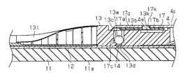
先ず、車両用ワイパ1の全体構成について説明し、その後に本実施の形態の要部について説明する。図1に示すように、車両用ワイパ1は、自動車の払拭面としてのフロントガラスに付着した雨滴等を払拭するためのものであって、ワイパアーム2と、該ワイパアーム2に連結されるワイパブレード3とから構成されている。ワイパアーム2は、その基端部がワイパモータ(図示略)の駆動力にて所定角度で往復回動されるピボット軸(図示略)に固定され、該ピボット軸の往復回動に伴って往復揺動運動を行う。尚、このワイパアーム2は、図示しない付勢機構により、フロントガラス(払拭面)側に付勢される。そして、ワイパアーム2の先端連結部4には、ワイパブレード3が連結される。 First, the overall configuration of the vehicle wiper 1 will be described, and then the main parts of the present embodiment will be described. As shown in FIG. 1, the vehicle wiper 1 is for wiping raindrops and the like adhering to the windshield as a wiping surface of an automobile, and is a wiper arm 2 and a wiper blade 3 connected to the wiper arm 2. It is composed of and. The wiper arm 2 is fixed to a pivot shaft (not shown) whose base end is reciprocally rotated at a predetermined angle by the driving force of a wiper motor (not shown), and reciprocates with the reciprocating rotation of the pivot shaft. Exercise. The wiper arm 2 is urged to the windshield (wiping surface) side by an urging mechanism (not shown). Then, the wiper blade 3 is connected to the tip connecting portion 4 of the wiper arm 2.

図2~図4に示すように、ワイパブレード3は、払拭面(フロントガラス)を払拭するための払拭部11aを有した長尺状のブレードラバー11と、ブレードラバー11の長手方向に沿って設けられ該ブレードラバー11に剛性と弾性を付与するための板ばね状のバッキング12とを備える。本実施の形態のブレードラバー11は、図3に示すように、長手方向直交方向断面が略長方形の基部11bと、該基部11bの幅方向中央から下方に延びる括れ部11cと、該括れ部11cから更に下方に延びる前記払拭部11aとを有する。又、本実施の形態のバッキング12は、図2及び図3に示すように、ワイパブレード3に1本のみ設けられるものであって、その長手方向の中央にバッキング係合部12aが形成されている。バッキング係合部12aは、バッキング12の幅方向の両側が幅方向中央側に切り欠かれた形状に形成されている。 As shown in FIGS. 2 to 4, the wiper blade 3 has a long blade rubber 11 having a wiping portion 11a for wiping the wiping surface (windshield), and the wiper blade 3 along the longitudinal direction of the blade rubber 11. The blade rubber 11 is provided with a leaf spring-shaped backing 12 for imparting rigidity and elasticity to the blade rubber 11. As shown in FIG. 3, the blade rubber 11 of the present embodiment has a base portion 11b having a substantially rectangular cross section in the longitudinal direction, a constricted portion 11c extending downward from the center of the base portion 11b in the width direction, and the constricted portion 11c. It has the wiping portion 11a extending further downward from the surface. Further, as shown in FIGS. 2 and 3, only one backing 12 of the present embodiment is provided on the wiper blade 3, and the backing engaging portion 12a is formed in the center in the longitudinal direction thereof. There is. The backing engaging portion 12a is formed in a shape in which both sides of the backing 12 in the width direction are cut out in the center side in the width direction.

又、図3に示すように、ワイパブレード3は、ブレードラバー11及びバッキング12の長手方向中央部におけるブレードラバー11の基部11b及びバッキング12の周囲を包囲してそれらの長手方向直交方向の移動を規制して保持するレバー保持部13aを有したホルダ本体としての連結レバー13を備える。 Further, as shown in FIG. 3, the wiper blade 3 surrounds the base portion 11b of the blade rubber 11 and the backing 12 at the central portion in the longitudinal direction of the blade rubber 11 and the backing 12, and moves them in the longitudinal direction orthogonal direction. A connecting lever 13 as a holder main body having a lever holding portion 13a for restricting and holding is provided.

詳しくは、連結レバー13は、硬質の樹脂材よりなり、図2~図4、及び図5(a),(b)に示すように、略直方体形状のレバー本体部13bと、図3及び図5(b)に示すように、該レバー本体部13bの下端面における幅方向両側から下方に延びてさらに幅方向内側に延びた腕状の前記レバー保持部13aとを有する。本実施の形態のレバー保持部13aは、図3に示すように、ブレードラバー11の基部11bにおける上端面にバッキング12を当接させた(載置した)状態で、該基部11b及びバッキング12を包囲する構成とされている。 Specifically, the connecting lever 13 is made of a hard resin material, and as shown in FIGS. 2 to 4 and 5 (a) and 5 (b), the lever body portion 13b having a substantially rectangular parallelepiped shape, and FIGS. 3 and 3 and FIGS. As shown in 5 (b), the lever main body portion 13b has an arm-shaped lever holding portion 13a extending downward from both sides in the width direction and further extending inward in the width direction on the lower end surface. As shown in FIG. 3, the lever holding portion 13a of the present embodiment has the base portion 11b and the backing 12 in a state where the backing 12 is in contact with (placed) the upper end surface of the base portion 11b of the blade rubber 11. It is supposed to be surrounded.

又、図2~図4、及び図5(a)に示すように、レバー本体部13bにおける長手方向一端側には、上方から前記レバー保持部13aまで連通するように貫通した上下貫通部13cが形成されている。上下貫通部13cは、上下方向から見て略4角形に形成されている。又、上下貫通部13cの下端部は、図4に示すように、その長手方向の間隔が小さくされ、後述するサポートパーツ14(図2参照)を収容するためのパーツ収容部13dとされている。 Further, as shown in FIGS. 2 to 4 and 5 (a), a vertical penetrating portion 13c penetrating from above to the lever holding portion 13a is provided on one end side in the longitudinal direction of the lever main body portion 13b. It is formed. The vertical penetrating portion 13c is formed in a substantially quadrangular shape when viewed from the vertical direction. Further, as shown in FIG. 4, the lower end portion of the upper and lower penetrating portions 13c is a part accommodating portion 13d for accommodating the support part 14 (see FIG. 2) described later by reducing the interval in the longitudinal direction thereof. ..

又、レバー本体部13bにおける長手方向一端側(上下貫通部13cと対応した位置)には、図2~図4、及び図5(a),(b)に示すように、その両側面(幅方向の側面)と直交する方向に貫通した軸挿通孔13eが形成されている。即ち、この軸挿通孔13eは、外部と前記上下貫通部13c(前記パーツ収容部13d)とを連通するように、言い換えると、前記上下貫通部13cの幅方向の内側面から外部に抜けるように形成されている。 Further, as shown in FIGS. 2 to 4 and FIGS. 5A and 5B, both side surfaces (widths) of the lever body portion 13b on one end side in the longitudinal direction (position corresponding to the vertical penetrating portion 13c). A shaft insertion hole 13e penetrating in a direction orthogonal to the side surface in the direction) is formed. That is, the shaft insertion hole 13e communicates with the outside and the upper and lower penetrating portions 13c (the parts accommodating portion 13d), in other words, so as to come out from the inner side surface in the width direction of the upper and lower penetrating portions 13c. It is formed.

又、図2及び図5(a),(b)に示すように、レバー本体部13bの両側面における略中央には、上下方向に延びる、詳しくは前記軸挿通孔13eの軸中心(回動軸中心)と同心の円弧に沿って延びる案内溝13fが形成されている。 Further, as shown in FIGS. 2 and 5 (a) and 5 (b), the center of the axis (rotation) of the shaft insertion hole 13e extending in the vertical direction at substantially the center on both side surfaces of the lever main body 13b. A guide groove 13f extending along an arc concentric with the center of the axis) is formed.

又、図5(a),(b)に示すように、レバー本体部13bの両側面における長手方向他端部には、上下方向に延びる抜止壁部13gが突出して形成されている。又、レバー本体部13bの上面における長手方向他端部には、図5(a)に示すように、前記抜止壁部13gの上端を繋ぐように幅方向に延びる上壁部13hが突出して形成されている。 Further, as shown in FIGS. 5A and 5B, a retaining wall portion 13g extending in the vertical direction is formed so as to project from the other end portion in the longitudinal direction on both side surfaces of the lever main body portion 13b. Further, as shown in FIG. 5A, an upper wall portion 13h extending in the width direction so as to connect the upper ends of the retaining wall portion 13g is formed so as to project from the other end portion in the longitudinal direction on the upper surface of the lever main body portion 13b. Has been done.

又、レバー本体部13bの両側面における下端部には、図5(a)に示すように、前記抜止壁部13gの下端から長手方向一端側まで延びる下壁部13iが突出して形成されている。又、下壁部13iの長手方向一端側端部には、図5(a)に示すように、前記軸挿通孔13eの軸中心(回動軸中心)と同心の円弧凹状に形成された対向面13jが形成されている。 Further, as shown in FIG. 5A, a lower wall portion 13i extending from the lower end of the retaining wall portion 13g to one end side in the longitudinal direction is formed at the lower end portions on both side surfaces of the lever main body portion 13b. .. Further, as shown in FIG. 5A, the lower wall portion 13i is formed in an arc concave shape concentric with the axis center (rotation axis center) of the shaft insertion hole 13e at the one end side end portion in the longitudinal direction. The surface 13j is formed.

図4及び図5(a)に示すように、又、レバー本体部13bの上面における略中央には、逃がし溝13kが形成されている。又、図1、図2及び図9に示すように、連結レバー13には、レバー本体部13bにおける長手方向一端側から長手方向先端に延びるとともに、後述するケース15のフィン部16に滑らかに繋がる形状の湾曲連結部13lが形成されている。 As shown in FIGS. 4 and 5A, a relief groove 13k is formed substantially in the center of the upper surface of the lever main body 13b. Further, as shown in FIGS. 1, 2 and 9, the connecting lever 13 extends from one end side in the longitudinal direction of the lever body portion 13b to the tip in the longitudinal direction and is smoothly connected to the fin portion 16 of the case 15 described later. A curved connecting portion 13l having a shape is formed.

このように構成された連結レバー13は、バッキング12との長手方向の移動が規制されて組み付けられる。詳しくは、まず連結レバー13のレバー保持部13a内に、バッキング12が長手方向に沿って挿入され、前記パーツ収容部13d(図3及び図4参照)と前記バッキング係合部12a(図2参照)の長手方向の位置が一致するように、長手方向の位置決めがなされる。そして、サポートパーツ14が、上方から上下貫通部13cを通されてパーツ収容部13dに嵌め込まれて(落とされて)、バッキング12(バッキング係合部12a)及び連結レバー13(パーツ収容部13d)と長手方向に係合するように組み付けられることで、連結レバー13とバッキング12とは長手方向の移動が規制(長手方向に位置決め)される。尚、本実施の形態のサポートパーツ14は、図3に示すように、長手方向から見て幅方向に延びる中央部14aと、該中央部14aの両端から下方に延びる一対の腕部14bとを有し、その中央部14aがパーツ収容部13d内に没入してパーツ収容部13dと長手方向に係合するとともに、各腕部14bがそれぞれバッキング係合部12aと長手方向に係合する構成となっている。 The connecting lever 13 configured in this way is assembled with restricted movement in the longitudinal direction with the backing 12. Specifically, first, the backing 12 is inserted into the lever holding portion 13a of the connecting lever 13 along the longitudinal direction, and the parts accommodating portion 13d (see FIGS. 3 and 4) and the backing engaging portion 12a (see FIG. 2) are inserted. ) Is positioned in the longitudinal direction so that the positions in the longitudinal direction match. Then, the support part 14 is passed through the upper and lower penetrating portions 13c from above and fitted (dropped) into the parts accommodating portion 13d, and the backing 12 (backing engaging portion 12a) and the connecting lever 13 (part accommodating portion 13d). By assembling so as to engage with the coupling lever 13 in the longitudinal direction, the movement of the connecting lever 13 and the backing 12 in the longitudinal direction is restricted (positioned in the longitudinal direction). As shown in FIG. 3, the support part 14 of the present embodiment has a central portion 14a extending in the width direction when viewed from the longitudinal direction, and a pair of arm portions 14b extending downward from both ends of the central portion 14a. The central portion 14a thereof is immersed in the parts accommodating portion 13d and engages with the parts accommodating portion 13d in the longitudinal direction, and each arm portion 14b engages with the backing engaging portion 12a in the longitudinal direction. It has become.

そして、連結レバー13には、前記ワイパアーム2に連結される連結部材としてのクリップ17がその両側面と直交する回動軸中心(前記ブレードラバー11の幅方向に沿った軸中心であって、前記軸挿通孔13eの軸中心)に回動可能に組み付けられる。 Then, on the connecting lever 13, the clip 17 as a connecting member connected to the wiper arm 2 is the center of the rotation axis orthogonal to both side surfaces thereof (the center of the axis along the width direction of the blade rubber 11). It is rotatably assembled to the shaft center of the shaft insertion hole 13e).

図2に示すように、クリップ17は、樹脂製であり、前記回動軸中心(前記軸挿通孔13eの軸中心)と対応した位置から組み付け状態で前記レバー本体部13bの両側面に沿って長手方向基端側に延びる一対の側壁17aと、それら一対の側壁17aの上端を繋ぐとともにレバー本体部13bの上面に沿って延びる上壁17bとを有する。 As shown in FIG. 2, the clip 17 is made of resin and is assembled from a position corresponding to the center of the rotating shaft (the center of the shaft of the shaft insertion hole 13e) along both side surfaces of the lever body portion 13b. It has a pair of side walls 17a extending toward the proximal end side in the longitudinal direction, and an upper wall 17b connecting the upper ends of the pair of side walls 17a and extending along the upper surface of the lever main body portion 13b.

このクリップ17の一対の側壁17aにおける内側面には、図2及び図3に示すように、前記軸挿通孔13eに挿入されることでクリップ17を回動可能に支持する支持軸17cが形成されている。そして、この支持軸17cは、図3に示すように、前記上下貫通部13c内に突出する長さに設定され、その先端部が前記パーツ収容部13dに嵌め込まれたサポートパーツ14の上面と当接して該サポートパーツ14の上方への抜けを規制するための抜け規制部17eとされている。尚、本実施の形態では、前記軸挿通孔13eと支持軸17cとが回動連結部を構成している。 As shown in FIGS. 2 and 3, a support shaft 17c that rotatably supports the clip 17 by being inserted into the shaft insertion hole 13e is formed on the inner side surface of the pair of side walls 17a of the clip 17. ing. Then, as shown in FIG. 3, the support shaft 17c is set to a length protruding into the upper and lower penetrating portions 13c, and the tip portion thereof is in contact with the upper surface of the support part 14 fitted in the part accommodating portion 13d. It is a dropout control unit 17e for restricting the support part 14 from coming out upward in contact with the support part 14. In the present embodiment, the shaft insertion hole 13e and the support shaft 17c form a rotary connecting portion.

又、図2、図6~図8に示すように、クリップ17の一対の側壁17aにおける外側面には、それぞれ係合凸部17fが形成されている。係合凸部17fは、側壁17aの長手方向一端側端部(支持軸17cの裏側)に形成されている。又、係合凸部17fは、側壁17aにおける上下方向の中央に形成されている。又、係合凸部17fは、上下の端面が長手方向に略沿って形成され、その下端面における長手方向他端部のみ他端側に向かうほど上方に湾曲した曲面とされている。 Further, as shown in FIGS. 2 and 6 to 8, engaging convex portions 17f are formed on the outer surfaces of the pair of side walls 17a of the clip 17, respectively. The engaging convex portion 17f is formed at one end side end portion in the longitudinal direction of the side wall 17a (the back side of the support shaft 17c). Further, the engaging convex portion 17f is formed at the center of the side wall 17a in the vertical direction. Further, the engaging convex portion 17f is a curved surface in which the upper and lower end faces are formed substantially along the longitudinal direction, and only the other end portion in the longitudinal direction of the lower end surface thereof is curved upward toward the other end side.

又、図6に示すように、クリップ17の前記上壁17bにおける前記回動軸中心側の端部(支持軸17c側端部であって長手方向一端側端部)には、自身の回動を許容するための切り欠き17gが形成されている。即ち、クリップ17の一対の側壁17aは、図2に示すように、前記支持軸17cよりも長手方向一端側にも僅かに延びているため、その部分にも上壁があると、その上壁が回動時にレバー本体部13bの上面に衝突する方向に回動することになるが、その上面に凹部を形成することなく、回動が許容されるように切り欠き17gが形成されている。 Further, as shown in FIG. 6, on the upper wall 17b of the clip 17, the end portion on the center side of the rotation shaft (the end portion on the support shaft 17c side and the end portion on one end side in the longitudinal direction) rotates itself. A notch 17g is formed to allow the above. That is, as shown in FIG. 2, the pair of side walls 17a of the clip 17 slightly extends to one end side in the longitudinal direction from the support shaft 17c, so if there is an upper wall in that portion as well, the upper wall thereof. Will rotate in the direction of colliding with the upper surface of the lever main body 13b at the time of rotation, but a notch 17g is formed so that rotation is permitted without forming a recess on the upper surface thereof.

又、図7及び図8に示すように、クリップ17の両側壁17aにおける下端面には、前記回動軸中心(支持軸17c及び軸挿通孔13eの軸中心)を中心とした円弧面17hが形成されている。この円弧面17hは、図8に示すように、前記連結レバー13の前記対向面13jと対向するように設定されている。尚、本実施の形態の円弧面17hは、初期状態(組み付けた直後の状態)で前記対向面13jと僅かな隙間を有して対向するように設定され、回動連結部(軸挿通孔13eと支持軸17c)で摩耗が生じた際に対向面13jと摺接するように設定されている。 Further, as shown in FIGS. 7 and 8, an arc surface 17h centered on the center of the rotation shaft (the center of the support shaft 17c and the shaft insertion hole 13e) is formed on the lower end surface of the side wall 17a of the clip 17. It is formed. As shown in FIG. 8, the arc surface 17h is set to face the facing surface 13j of the connecting lever 13. The arcuate surface 17h of the present embodiment is set so as to face the facing surface 13j with a slight gap in the initial state (state immediately after assembly), and the rotary connecting portion (shaft insertion hole 13e) is set. And the support shaft 17c) is set to be in sliding contact with the facing surface 13j when wear occurs.

又、クリップ17の両側壁17aにおける前記回動軸中心(支持軸17c)から長手方向他端側に離間した位置の下端面は、図7及び図8に示すように、前記回動軸中心と対応した位置の下端面(即ち円弧面17h)より位置が高い上方下端面17iとされている。 Further, as shown in FIGS. 7 and 8, the lower end surface of the clip 17 on both side walls 17a at a position separated from the center of the rotation shaft (support shaft 17c) on the other end side in the longitudinal direction is the center of the rotation shaft. The upper lower end surface 17i is higher than the lower end surface (that is, the arc surface 17h) at the corresponding position.

即ち、本実施の形態のクリップ17における両側壁17aの下端面は、回動軸中心(支持軸17c)の下方部分のみが上方下端面17iより円弧凸状に突出した円弧面17hとされている。 That is, the lower end surface of both side walls 17a in the clip 17 of the present embodiment is an arc surface 17h in which only the lower portion of the center of the rotation axis (support shaft 17c) protrudes in an arc convex shape from the upper lower end surface 17i. ..

又、図8に示すように、クリップ17の両側壁17aの長手方向他端部は、前記連結レバー13に組み付けられた状態で、前記抜止壁部13gとの長手方向の間に上下方向に沿って延びる隙間Sが生じるように設定されている。 Further, as shown in FIG. 8, the other end portion of the clip 17 on both side walls 17a in the longitudinal direction is along the vertical direction between the clip 17 and the retaining wall portion 13g in the longitudinal direction in a state of being assembled to the connecting lever 13. It is set so that a gap S extending from the surface is generated.

又、図7に示すように、クリップ17の両側壁17aにおける内側面には、前記案内溝13f(図5参照)に嵌る案内凸部17jが形成されている。この案内凸部17jは、前記案内溝13fに嵌った状態で該案内溝13fに案内されつつ案内溝13fの上下方向の終端位置に応じて連結レバー13に対するクリップ17のそれ以上の回動を規制するためのものである。 Further, as shown in FIG. 7, a guide convex portion 17j that fits into the guide groove 13f (see FIG. 5) is formed on the inner side surface of the side wall 17a of the clip 17. The guide convex portion 17j is guided by the guide groove 13f in a state of being fitted in the guide groove 13f, and restricts further rotation of the clip 17 with respect to the connecting lever 13 according to the vertical end position of the guide groove 13f. It is for doing.

又、図2に示すように、クリップ17には、ワイパアーム2に設けられた後述する係止孔4eに嵌りワイパアーム2の着脱方向(ブレードラバー11等の長手方向)に係合する押下可能な係止凸部17kが形成されている。詳述すると、クリップ17は、ワイパアーム2の着脱方向(ブレードラバー11等の長手方向)とは異なる方向(本実施形態の弾性片部17lはワイパブレード3の幅方向、より詳しくは、ワイパブレード3の長手方向と直交する方向)に延びて先端部に前記係止凸部17kが接続された弾性片部17lと、ワイパアーム2の抜け方向(図4中、右方向)への係止凸部17kの移動を規制する規制部17mとを有する。 Further, as shown in FIG. 2, the clip 17 has a pressable engagement that fits into a locking hole 4e provided in the wiper arm 2 and engages with the wiper arm 2 in the attachment / detachment direction (longitudinal direction of the blade rubber 11 or the like). A stop convex portion 17k is formed. More specifically, the clip 17 is in a direction different from the attachment / detachment direction of the wiper arm 2 (longitudinal direction of the blade rubber 11 or the like) (the elastic piece portion 17l of the present embodiment is the width direction of the wiper blade 3, more specifically, the wiper blade 3). An elastic piece portion 17l extending in a direction orthogonal to the longitudinal direction of the wiper arm 2 and having the locking convex portion 17k connected to the tip portion thereof, and a locking convex portion 17k in the pulling direction (right direction in FIG. 4) of the wiper arm 2. It has a regulation unit 17m that regulates the movement of the rubber.

本実施形態の弾性片部17lでは、その基端部、より詳しくは弾性片部17lと側壁17aとの接続部位が、弾性片部17lの撓み軸Z(図11参照)となり、その撓み軸Zはワイパアーム2(先端連結部4)の着脱方向に沿うように形成されている。そして、弾性片部17lは、その基端部が側壁17aの上下方向中間部に接続され、まず側壁17aに沿って上方に延び、側壁17aと上壁17bとの境界部分に折曲部17nを有して折曲部17nから上壁17bに沿って該上壁17bの幅方向中間部まで延び、その先端部に係止凸部17kが接続され、係止凸部17kは上壁17bから上方に突出するように設けられている。尚、本実施形態の係止凸部17kは上方から見てほぼ正方形に形成されている。又、本実施形態の弾性片部17lは、その全体が、係止凸部17kの前記着脱方向(ブレードラバー11等の長手方向)の寸法よりも小さい寸法の狭部とされている。 In the elastic piece portion 17l of the present embodiment, the base end portion, more specifically, the connection portion between the elastic piece portion 17l and the side wall 17a becomes the bending axis Z (see FIG. 11) of the elastic piece portion 17l, and the bending axis Z thereof. Is formed along the attachment / detachment direction of the wiper arm 2 (tip connecting portion 4). The base end portion of the elastic piece portion 17l is connected to the vertical intermediate portion of the side wall 17a, first extends upward along the side wall 17a, and the bent portion 17n is provided at the boundary portion between the side wall 17a and the upper wall 17b. It extends from the bent portion 17n along the upper wall 17b to the intermediate portion in the width direction of the upper wall 17b, the locking convex portion 17k is connected to the tip portion thereof, and the locking convex portion 17k is upward from the upper wall 17b. It is provided so as to protrude from the surface. The locking convex portion 17k of the present embodiment is formed to be substantially square when viewed from above. Further, the elastic piece portion 17l of the present embodiment is a narrow portion having a dimension smaller than the dimension of the locking convex portion 17k in the attachment / detachment direction (longitudinal direction of the blade rubber 11 or the like).

又、本実施形態の係止凸部17k及び弾性片部17lは、上壁17b及び側壁17aの同一平面上にスリット17pにて区画されて形成されるものであり、前記規制部17mは、係止凸部17kと対応した上壁17bのスリット側端面にて構成されている。又、係止凸部17kは、連結レバー13の前記逃がし溝13k(図2及び図4参照)と対応した位置に形成され、該逃がし溝13kによって、組み付けられた状態(図4及び図6参照)での押下が許容されることになる。 Further, the locking convex portion 17k and the elastic piece portion 17l of the present embodiment are formed by being partitioned by a slit 17p on the same plane of the upper wall 17b and the side wall 17a, and the restricting portion 17m is engaged. It is composed of a slit-side end surface of the upper wall 17b corresponding to the stop convex portion 17k. Further, the locking convex portion 17k is formed at a position corresponding to the relief groove 13k (see FIGS. 2 and 4) of the connecting lever 13, and is assembled by the relief groove 13k (see FIGS. 4 and 6). ) Will be allowed to be pressed.

又、図1及び図2に示すように、ワイパブレード3は、連結レバー13(レバー保持部13a)の長手方向両側におけるブレードラバー11の基部11b及びバッキング12の周囲を包囲してそれらの長手方向直交方向の移動を規制して保持するケース保持部15a(図2参照)をそれぞれ有した一対のケース15を備えている。 Further, as shown in FIGS. 1 and 2, the wiper blade 3 surrounds the base portion 11b of the blade rubber 11 and the backing 12 on both sides in the longitudinal direction of the connecting lever 13 (lever holding portion 13a) in the longitudinal direction thereof. It includes a pair of cases 15 each having a case holding portion 15a (see FIG. 2) that regulates and holds the movement in the orthogonal direction.

ケース15は、軟質の(可撓性を有する)樹脂材よりなり、そのケース保持部15aの形状は、前記レバー保持部13aと同様の形状とされている。即ち、レバー保持部13aと各ケース保持部15aとは、組み付けられた状態で長手方向に連なって、ブレードラバー11の基部11b及びバッキング12をその長手方向全体に亘って包囲(収容)する構成とされている。 The case 15 is made of a soft (flexible) resin material, and the shape of the case holding portion 15a is the same as that of the lever holding portion 13a. That is, the lever holding portion 13a and each case holding portion 15a are connected in the longitudinal direction in an assembled state, and surround (accommodate) the base portion 11b and the backing 12 of the blade rubber 11 over the entire longitudinal direction. Has been done.

又、ケース15の上面には、ゴム材又はエラストマー材よりなり、走行風を払拭面側への押圧力に変換するためのフィン部16がニ色成形により設けられている。具体的には、フィン部16は、ワイパブレード3の停止位置において車両後方側に向かうほど(払拭面から)高くなる湾曲面を有した形状に形成されている。そして、連結レバー13の前記湾曲連結部13lは、図2及び図9に示すように、略直方体形状のレバー本体部13bからフィン部16側に向かって徐々に前記湾曲面と対応した形状となるように形成されている。 Further, on the upper surface of the case 15, a fin portion 16 made of a rubber material or an elastomer material and for converting the running wind into a pressing force toward the wiping surface side is provided by two-color molding. Specifically, the fin portion 16 is formed in a shape having a curved surface that becomes higher (from the wiping surface) toward the rear side of the vehicle at the stop position of the wiper blade 3. Then, as shown in FIGS. 2 and 9, the curved connecting portion 13l of the connecting lever 13 gradually has a shape corresponding to the curved surface from the substantially rectangular parallelepiped lever main body portion 13b toward the fin portion 16. It is formed like this.

又、本実施の形態では、前記湾曲連結部13lと対応した側のケース15(フィン部16含む)と連結レバー13(湾曲連結部13l)との連結部分は、互いの上端面が面一となるように設定、言い換えれば、両者の連結部分の形状が連続的に移行するように形成されている。又、そのケース15(フィン部16含む)には、図2及び図9に示すように、前記連結レバー13(その湾曲連結部13l)にて上面が覆われるように長手方向に延びる段差部15bが形成されている。 Further, in the present embodiment, the upper end surfaces of the connecting portion between the case 15 (including the fin portion 16) and the connecting lever 13 (curved connecting portion 13l) on the side corresponding to the curved connecting portion 13l are flush with each other. In other words, the shape of the connecting portion between the two is formed so as to continuously shift. Further, in the case 15 (including the fin portion 16), as shown in FIGS. 2 and 9, a step portion 15b extending in the longitudinal direction so that the upper surface is covered by the connecting lever 13 (the curved connecting portion 13l) is covered. Is formed.

又、ワイパブレード3は、図1に示すように、バッキング12の長手方向両端に固定されて、該バッキング12の長手方向端部と、ケース15(フィン部16含む)の長手方向端部と、ブレードラバー11の基部11bにおける長手方向端部とを覆うキャップ18を備えている。 Further, as shown in FIG. 1, the wiper blade 3 is fixed to both ends in the longitudinal direction of the backing 12, and has a longitudinal end portion of the backing 12 and a longitudinal end portion of the case 15 (including the fin portion 16). A cap 18 is provided that covers the longitudinal end of the blade rubber 11 at the base 11b.

上記のように構成されたワイパブレード3は、クリップ17を介してワイパアーム2の先端部(先端連結部4)に連結される。具体的には、図2及び図10に示すように、ワイパアーム2の先端連結部4には、クリップ17の(上壁17bの)上面を略覆う上被覆壁4aと、クリップ17の両側面(両側壁17aの外側面)を略覆う一対の対向壁4bとが形成されている。一対の対向壁4bは、幅方向(払拭方向)に互いに対向している。一対の対向壁4bには、それぞれ係合凹部4cが形成されている。各係合凹部4cは、一対の対向壁4bにおける上下方向の中央部分に、ワイパアーム2の先端側(長手方向一端側)が開口するように形成されている。 The wiper blade 3 configured as described above is connected to the tip end portion (tip connecting portion 4) of the wiper arm 2 via the clip 17. Specifically, as shown in FIGS. 2 and 10, the tip connecting portion 4 of the wiper arm 2 has an upper covering wall 4a that substantially covers the upper surface (of the upper wall 17b) of the clip 17, and both side surfaces (both sides of the clip 17). A pair of facing walls 4b that substantially covers the outer surfaces of both side walls 17a) are formed. The pair of facing walls 4b face each other in the width direction (wiping direction). Engagement recesses 4c are formed in each of the pair of facing walls 4b. Each engaging recess 4c is formed so that the tip end side (one end side in the longitudinal direction) of the wiper arm 2 opens at the central portion in the vertical direction of the pair of facing walls 4b.

クリップ17は、ワイパアーム2の下側から一対の対向壁4bの間に嵌合され、先端連結部4に対して相対的にワイパアーム2の基端側へ移動される。これにより、クリップ17の係合凸部17fが一対の対向壁4bの係合凹部4cに挿入され、係合凸部17fと係合凹部4cとが上下方向に係合する。又、上記のようにクリップ17が先端連結部4に対して相対移動されると、クリップ17の係止凸部17kがワイパアーム2の係止孔4eに嵌合する。これにより、クリップ17が先端連結部4に係止される。尚、一対の対向壁4bには、上下方向に前記バッキング12と一致する位置まで下方に延びたラップ部4fが形成されている。 The clip 17 is fitted between the pair of facing walls 4b from the lower side of the wiper arm 2 and is moved to the proximal end side of the wiper arm 2 relative to the tip connecting portion 4. As a result, the engaging convex portion 17f of the clip 17 is inserted into the engaging concave portion 4c of the pair of facing walls 4b, and the engaging convex portion 17f and the engaging concave portion 4c are engaged in the vertical direction. Further, when the clip 17 is relatively moved with respect to the tip connecting portion 4 as described above, the locking convex portion 17k of the clip 17 fits into the locking hole 4e of the wiper arm 2. As a result, the clip 17 is locked to the tip connecting portion 4. The pair of facing walls 4b are formed with a lap portion 4f extending downward to a position corresponding to the backing 12 in the vertical direction.

又、図10に示すように、先端連結部4が有する一対の対向壁4bの内側面には、互いに幅方向中央側に突出する突起4dがそれぞれ打ち出し形成されている。これら一対の突起4dは、前述した隙間S(図8及び図11参照)に対応している。隙間Sは、両側壁17a(一対の側壁17a)の長手方向他端面17rと、両抜止壁部13g(一対の抜止壁部13g)との間にそれぞれ形成されている。つまり、一対の側壁17aの長手方向他端面17rと一対の抜止壁部13gとは、一対の隙間Sを隔ててワイパブレード3の長手方向に対向している。そして、上記のように一対の対向壁4b間にクリップ17が嵌合される際には、一対の突起4dが上側から下側へ向けて一対の隙間Sを通過する構成になっている。 Further, as shown in FIG. 10, protrusions 4d protruding toward the center in the width direction are formed on the inner side surfaces of the pair of facing walls 4b of the tip connecting portion 4, respectively. These pair of protrusions 4d correspond to the above-mentioned gap S (see FIGS. 8 and 11). The gap S is formed between the other end surface 17r in the longitudinal direction of both side walls 17a (a pair of side walls 17a) and both retaining wall portions 13g (a pair of retaining wall portions 13g). That is, the other end surface 17r in the longitudinal direction of the pair of side walls 17a and the pair of retaining wall portions 13g face each other in the longitudinal direction of the wiper blade 3 with a pair of gaps S interposed therebetween. When the clip 17 is fitted between the pair of facing walls 4b as described above, the pair of protrusions 4d passes through the pair of gaps S from the upper side to the lower side.

又、図8に示すように、一対の突起4dは、クリップ17に先端連結部4が組み付けられた状態で、クリップ17の上方下端面17iと当接する位置に形成されている。又、一対の突起4dは、クリップ17に先端連結部4が組み付けられた状態で、案内凸部17j(図7参照)の下端と当接する位置に形成され、案内溝13f(図5参照)の下方の終端と当接することで連結レバー13に対するクリップ17及び先端連結部4の一方の回動を規制するように設けられている。即ち、一対の突起4dは、クリップ17に先端連結部4が組み付けられた状態では、前記案内凸部17jと一体的となり剛性を互いに高め合いつつ、前記一方の回動を規制するように設けられている。 Further, as shown in FIG. 8, the pair of protrusions 4d is formed at a position where the tip connecting portion 4 is assembled to the clip 17 and abuts on the upper lower end surface 17i of the clip 17. Further, the pair of protrusions 4d is formed at a position where the tip connecting portion 4 is assembled to the clip 17 and is in contact with the lower end of the guide convex portion 17j (see FIG. 7), and is formed in the guide groove 13f (see FIG. 5). It is provided so as to restrict the rotation of one of the clip 17 and the tip connecting portion 4 with respect to the connecting lever 13 by abutting against the lower end. That is, the pair of protrusions 4d is provided so as to regulate the rotation of one of the protrusions 4d while the tip connecting portion 4 is assembled to the clip 17 and is integrated with the guide convex portion 17j to increase the rigidity of each other. ing.

(本実施の形態の要部)
次に、本実施の形態の要部について説明する。尚、本実施の形態では、ワイパアーム2の先端連結部4、ワイパブレード3の連結レバー13、及びクリップ17が、幅方向(払拭方向)において対称な形状に形成されている。このため、以下の説明では、一対の対向壁4b、一対の抜止壁部13g、一対の側壁17a、一対の突起4d、及び一対の隙間Sを、単に「対向壁4b」、「抜止壁部13g」、「側壁17a」、「突起4d」、及び「隙間S」と称する場合がある。
(Main part of this embodiment)
Next, a main part of the present embodiment will be described. In this embodiment, the tip connecting portion 4 of the wiper arm 2, the connecting lever 13 of the wiper blade 3, and the clip 17 are formed in a symmetrical shape in the width direction (wiping direction). Therefore, in the following description, the pair of facing walls 4b, the pair of retaining wall portions 13g, the pair of side walls 17a, the pair of protrusions 4d, and the pair of gaps S are simply referred to as "opposing wall 4b" and "removing wall portion 13g". , "Wall 17a", "Protrusion 4d", and "Gap S".

本実施の形態では、図11に示されるように、抜止壁部13gは、払拭方向から見てクランク状(略クランク状)に形成されている。具体的には、抜止壁部13gは、上壁部13hの幅方向端部から下側へ延びる上部13g1と、上部13g1の下端から下側かつワイパブレード3の長手方向他端側へ斜めに延びる傾斜部13g2と、傾斜部13g2の下端から下側へ延びる下部13g3とによって構成されている。上記の傾斜部13g2は、ワイパブレード3の長手方向一端側を向く面が、ワイパブレード3の長手方向他端側へ向かって下り勾配の傾斜面13mとされている。尚、図11では、図面を見易くするために、クリップ17を概略的に記載している。 In the present embodiment, as shown in FIG. 11, the retaining wall portion 13g is formed in a crank shape (substantially crank shape) when viewed from the wiping direction. Specifically, the retaining wall portion 13g extends diagonally from the upper end 13g1 extending downward from the widthwise end portion of the upper wall portion 13h and downward from the lower end of the upper portion 13g1 and toward the other end side in the longitudinal direction of the wiper blade 3. It is composed of an inclined portion 13g2 and a lower portion 13g3 extending downward from the lower end of the inclined portion 13g2. In the inclined portion 13g2, the surface of the wiper blade 3 facing the one end side in the longitudinal direction is an inclined surface 13m having a downward slope toward the other end side of the wiper blade 3 in the longitudinal direction. In addition, in FIG. 11, the clip 17 is schematically shown in order to make the drawing easier to see.

又、本実施の形態では、クリップ17の一対の側壁17aの長手方向他端面(長手方向他端部)17rは、払拭方向から見て略クランク状に形成されている。具体的には、一対の側壁17aの長手方向他端面17rは、クリップ17の上壁17bの上面から下側かつワイパブレード3の長手方向他端側へ斜めに延びる上傾斜面17r1と、上傾斜面17r1の下端から下側へ延びる上縦面17r2と、上縦面17r2の下端から下側かつワイパブレード3の長手方向他端側へ斜めに延びる下傾斜面17r3と、下傾斜面17r3の下端から下側へ延びる下縦面17r4とによって構成されている。尚、長手方向他端面17rに関して記載した上記の方向は、クリップ17が連結レバー13に対して最も下側へ回動した姿勢(図11に実線で示すクリップ17参照;以下、この姿勢を「第1の姿勢」と称する)とされた状態での方向を示すものとする。 Further, in the present embodiment, the other end surface in the longitudinal direction (the other end in the longitudinal direction) 17r of the pair of side walls 17a of the clip 17 is formed in a substantially crank shape when viewed from the wiping direction. Specifically, the other end surface 17r in the longitudinal direction of the pair of side walls 17a is inclined upward with the upper inclined surface 17r1 extending downward from the upper surface of the upper wall 17b of the clip 17 and diagonally extending to the other end side in the longitudinal direction of the wiper blade 3. An upper vertical surface 17r2 extending downward from the lower end of the surface 17r1, a lower inclined surface 17r3 extending diagonally from the lower end of the upper vertical surface 17r2 to the lower side and the other end side in the longitudinal direction of the wiper blade 3, and a lower end of the lower inclined surface 17r3. It is composed of a lower vertical surface 17r4 extending downward from the surface. In the above-mentioned direction described with respect to the other end surface 17r in the longitudinal direction, the posture in which the clip 17 is rotated most downward with respect to the connecting lever 13 (see the clip 17 shown by the solid line in FIG. 11; hereinafter, this posture is referred to as “the first”. It shall indicate the direction in the state of "1 posture").

上記第1の姿勢の状態では、隙間Sは、上側の部位が下側の部位よりも側壁17aの長手方向一端部側に位置するようにクランク状(略クランク状)に曲がった形状となる。この第1の姿勢の状態では、隙間Sの幅寸法が突起4dの幅寸法よりも若干広くなり、突起4dが隙間Sを上下に通過可能となるように構成されている。つまり、本実施の形態では、抜止壁部13gは、クリップ17の第1の姿勢において側壁17aの長手方向他端面17rと第1の間隔S1(図11参照)を有してワイパブレード3の長手方向に対向する構成になっており、突起4dは、第1の間隔S1よりも小さい幅寸法を有している。また、上記のようにクランク状に曲がった形状となった隙間Sは、本発明における「通路」に相当する。 In the state of the first posture, the gap S has a shape bent in a crank shape (substantially crank shape) so that the upper portion is located on the one end side in the longitudinal direction of the side wall 17a with respect to the lower portion. In this first posture state, the width dimension of the gap S is slightly wider than the width dimension of the protrusion 4d, and the protrusion 4d is configured to be able to pass through the gap S up and down. That is, in the present embodiment, the retaining wall portion 13g has the other end surface 17r in the longitudinal direction of the side wall 17a and the first distance S1 (see FIG. 11) in the first posture of the clip 17, and the length of the wiper blade 3 is long. The protrusions 4d are configured to face each other in the direction, and the protrusions 4d have a width dimension smaller than that of the first spacing S1. Further, the gap S having a shape bent like a crank as described above corresponds to the "passage" in the present invention.

一方、クリップ17が連結レバー13に対して最も上側へ回動した姿勢(図11に二点鎖線で示されるクリップ17参照;以下、この姿勢を「第2の姿勢」と称する)とされた状態では、上記第1の姿勢の状態よりも隙間Sが狭められる。この第2の姿勢の状態では、隙間Sの幅寸法S2(図11参照)が突起4dの幅寸法よりも狭くなり(図11においてS2<S1)、突起4dが隙間Sを上下に通過不能となるように構成されている。つまり、本実施の形態では、上記第2の姿勢における側壁17aの長手方向他端面17rと抜止壁部13gとの間の第2の間隔S2は、の突起4dの幅寸法よりも小さく設定されている On the other hand, the state in which the clip 17 is rotated upward with respect to the connecting lever 13 (see the clip 17 shown by the two-dot chain line in FIG. 11; hereinafter, this posture is referred to as a "second posture"). Then, the gap S is narrower than the state of the first posture. In this second posture state, the width dimension S2 of the gap S (see FIG. 11) becomes narrower than the width dimension of the protrusion 4d (S2 <S1 in FIG. 11), and the protrusion 4d cannot pass through the gap S up and down. It is configured to be. That is, in the present embodiment, the second distance S2 between the other end surface 17r in the longitudinal direction of the side wall 17a and the retaining wall portion 13g in the second posture is set smaller than the width dimension of the protrusion 4d. Are

又、本実施の形態では、図2及び図6に示されるように、クリップ17の上壁17bにおいて、係止凸部17kよりもクリップ17の長手方向一端側には、付勢部としてのバネ片部17qが一体に形成されている。バネ片部17qは、上壁17bの一部が下側に切り起こされたものであり、クリップ17の長手方向他端側へ向かうほど下側へ向かうように傾斜している。このクリップ17は、先端部がレバー本体部13bの上面と接触しており、クリップ17を連結レバー13に対して上側へ(即ち第1の姿勢から第2の姿勢に向けて回動力が支持軸17cの軸線周りに回動力が作用するように)付勢している。このため、ワイパアーム2の先端連結部4にクリップ17が組み付けられていない状態では、クリップ17が第2の姿勢、即ち突起4dが隙間Sを通過不能となる姿勢に保持される構成になっている。 Further, in the present embodiment, as shown in FIGS. 2 and 6, in the upper wall 17b of the clip 17, a spring as an urging portion is provided on one end side of the clip 17 in the longitudinal direction with respect to the locking convex portion 17k. One piece 17q is integrally formed. A part of the upper wall 17b of the spring piece portion 17q is cut up to the lower side, and the spring piece portion 17q is inclined so as to go downward toward the other end side in the longitudinal direction of the clip 17. The tip of the clip 17 is in contact with the upper surface of the lever body 13b, and the rotational force supports the clip 17 upward with respect to the connecting lever 13 (that is, from the first posture to the second posture). It is urged (so that rotational power acts around the axis of 17c). Therefore, when the clip 17 is not attached to the tip connecting portion 4 of the wiper arm 2, the clip 17 is held in a second posture, that is, a posture in which the protrusion 4d cannot pass through the gap S. ..

尚、上記第2の姿勢は、クリップ17の案内凸部17jが連結レバー13の案内溝13fの上端面に当接した状態であり、クリップ17は連結レバー13に対して第2の姿勢よりも上側への回動を規制される構成になっている。つまり、案内凸部17j及び案内溝13fは、突起4dが隙間Sを通過不能となる位置よりも上側へのクリップ17の回動を制限する制限部とされている。 The second posture is a state in which the guide convex portion 17j of the clip 17 is in contact with the upper end surface of the guide groove 13f of the connecting lever 13, and the clip 17 is in a state of being in contact with the upper end surface of the guide groove 13f of the connecting lever 13. The structure is such that the rotation to the upper side is restricted. That is, the guide convex portion 17j and the guide groove 13f are restricted portions that restrict the rotation of the clip 17 upward from the position where the protrusion 4d cannot pass through the gap S.

又、本実施の形態では、ブレードレバー11による払拭面(フロントガラス)の払拭時に、先端連結部4に対するクリップ17の係止が解除された場合、即ち例えば係止凸部17kが破損した場合や係止凸部17kが意図せずに押下された場合、連結レバー13の抜止壁部13gとワイパアーム2の突起4dとが接触する。その際には、図12に示されるように、突起4dが抜止壁部13gの傾斜面13mに対してワイパアーム2の基端側向きに接触することにより、突起4dに対して下向きの分力Frが付与される構成になっている。つまり、上記払拭時に上記係止が解除された場合、ワイパブレード3に作用する遠心力によって、抜止壁部13g(連結レバー13)が対向壁4bに対して相対的にワイパアーム2の先端側へ移動し、抜止壁部13gの傾斜面13mが突起4dに押し当てられる。その際に突起4dが傾斜面13mから受ける反力Fの分力Frが下向きになるように、傾斜面13mの傾斜角度が設定されている。この傾斜面13mは、本発明における「分力付与面」に相当する。 Further, in the present embodiment, when the wiping surface (windshield) is wiped by the blade lever 11, the clip 17 is unlocked from the tip connecting portion 4, that is, for example, when the locking convex portion 17k is damaged. When the locking convex portion 17k is unintentionally pressed, the retaining wall portion 13g of the connecting lever 13 and the protrusion 4d of the wiper arm 2 come into contact with each other. At that time, as shown in FIG. 12, the protrusion 4d comes into contact with the inclined surface 13m of the retaining wall portion 13g toward the base end side of the wiper arm 2, so that the component force Fr downward with respect to the protrusion 4d Is given. That is, when the locking is released at the time of wiping, the retaining wall portion 13g (connecting lever 13) moves relatively to the tip end side of the wiper arm 2 with respect to the facing wall 4b due to the centrifugal force acting on the wiper blade 3. Then, the inclined surface 13m of the retaining wall portion 13g is pressed against the protrusion 4d. At that time, the inclination angle of the inclined surface 13m is set so that the component force Fr of the reaction force F received by the protrusion 4d from the inclined surface 13m faces downward. This inclined surface 13m corresponds to the "component force applying surface" in the present invention.

尚、図13に示される変形例のように、クリップ17の第1の姿勢で隙間Sが斜めに傾斜した形状となる構成(抜止壁部13gが払拭方向から見て傾斜した形状に形成された構成)にしてもよい。この変形例に係る抜止壁部13gは、ワイパブレード3の長手方向他端側へ向かって下り勾配に傾斜しており、ワイパブレード3の長手方向一端側を向く面の全面が傾斜面13mとされている。また、この変形例では、クリップ17の側壁17aの長手方向他端面17rが、ワイパブレード3の長手方向他端側へ向かって下り勾配に傾斜した傾斜面とされている。この変形例においても、抜止壁部13gの傾斜面13mが突起4dに押し当てられた際に、突起4dに対して下向きの分力Frが作用するように、傾斜面13mの傾斜角度が設定されている。尚、本発明における「分力付与面」は、傾斜面13mに限らず、湾曲面であってもよい。 As in the modified example shown in FIG. 13, the gap S is formed in a slanted shape in the first posture of the clip 17 (the retaining wall portion 13 g is formed in a slanted shape when viewed from the wiping direction. Configuration) may be used. The retaining wall portion 13g according to this modification is inclined downward toward the other end side in the longitudinal direction of the wiper blade 3, and the entire surface of the wiper blade 3 facing the one end side in the longitudinal direction is an inclined surface 13 m. ing. Further, in this modification, the other end surface 17r in the longitudinal direction of the side wall 17a of the clip 17 is an inclined surface inclined downward toward the other end side in the longitudinal direction of the wiper blade 3. Also in this modification, the inclination angle of the inclined surface 13m is set so that the downward component force Fr acts on the protrusion 4d when the inclined surface 13m of the retaining wall portion 13g is pressed against the protrusion 4d. ing. The "component force applying surface" in the present invention is not limited to the inclined surface 13 m, and may be a curved surface.

次に、図15~図22を用いて、ワイパアーム2の先端連結部4に対するクリップ17の組み付け手順及び取り外し手順について説明し、その説明の中で、先端連結部4からのクリップ17の外れ防止の原理について併せて説明する。なお、図16~図22では、バネ片部17qの図示を省略している。 Next, with reference to FIGS. 15 to 22, the procedure for assembling and removing the clip 17 with respect to the tip connecting portion 4 of the wiper arm 2 will be described, and in the description thereof, the clip 17 will be prevented from coming off from the tip connecting portion 4. The principle will also be explained. In FIGS. 16 to 22, the spring piece portion 17q is not shown.

図15には、クリップ17がワイパアーム2の先端連結部4に組み付けられる前の状態が図示されている。この状態では、クリップ17は、バネ片部17qの付勢力によって第2の姿勢に保持されている。このクリップ17が先端連結部4に組み付けられる際には、先ず図16に示されるように、一対の対向壁4b間にクリップ17が嵌合(配置)され、クリップ17の長手方向他端面17rの上傾斜面17r1(段部)に突起4dが宛がわれる。その状態で先端連結部4がワイパブレード3に対して相対的に押し下げられることにより、図17に示されるようにクリップ17がバネ片部17qの付勢力に抗して下側へ回動され、第1の姿勢とされる。これにより、隙間Sが広げられ、突起4dが隙間S(即ちクランク状の通路)を通過可能となる。 FIG. 15 shows a state before the clip 17 is assembled to the tip connecting portion 4 of the wiper arm 2. In this state, the clip 17 is held in the second posture by the urging force of the spring piece portion 17q. When the clip 17 is assembled to the tip connecting portion 4, the clip 17 is first fitted (arranged) between the pair of facing walls 4b as shown in FIG. 16, and the other end surface 17r in the longitudinal direction of the clip 17 is fitted (arranged). The protrusion 4d is addressed to the upper inclined surface 17r1 (step portion). In this state, the tip connecting portion 4 is pushed down relative to the wiper blade 3, so that the clip 17 is rotated downward against the urging force of the spring piece portion 17q as shown in FIG. It is the first posture. As a result, the gap S is widened, and the protrusion 4d can pass through the gap S (that is, a crank-shaped passage).

そして、更に先端連結部4がワイパブレード3に対して相対的に押し下げられることにより、図18に示されるように突起4dが隙間Sを通過して上方下端面17iの下側に至る。その状態で、クリップ17が先端連結部4に対して相対的にワイパアーム2の基端側へ移動されると、図19に示されるように、クリップ17の係合凸部17fが一対の対向壁4bの係合凹部4cに挿入されると共に、クリップ17の係止凸部17kがワイパアーム2の係止孔4eに嵌合する。これにより、クリップ17が先端連結部4に係止され、ワイパアーム2に対するワイパブレード3の組付けが完了する。 Then, the tip connecting portion 4 is further pushed down relative to the wiper blade 3, so that the protrusion 4d passes through the gap S and reaches the lower side of the upper lower end surface 17i as shown in FIG. In this state, when the clip 17 is moved relatively to the proximal end side of the wiper arm 2 with respect to the tip connecting portion 4, as shown in FIG. 19, the engaging convex portions 17f of the clip 17 are paired with the facing wall. It is inserted into the engaging recess 4c of 4b, and the locking convex portion 17k of the clip 17 fits into the locking hole 4e of the wiper arm 2. As a result, the clip 17 is locked to the tip connecting portion 4, and the assembly of the wiper blade 3 to the wiper arm 2 is completed.

一方、ワイパアーム2からワイパブレード3を取り外すために係止凸部17kが意図的に押下された場合や、係止孔4eに対する係止凸部17kの嵌合状態が意図せずに解除された場合には、図20に示されるように係合凸部17fが係合凹部4cから抜け出すことにより、クリップ17がバネ片部17qの付勢力によって上側へ回動され、第2の姿勢となる。この状態では、隙間Sが狭められ、突起4dが隙間Sを下側から上側に通過不能となる(突起4dの通過経路が遮断される)ので、クリップ17が一対の対向壁4b間から完全に抜け出せなくなり、ワイパアーム2に対するワイパブレード3の連結状態が維持される。つまり、本実施の形態では、先端連結部4に対するクリップ17の係止が解除された際には、少なくとも一対の対向壁4b間からクリップ17が抜け出す途中で一対の側壁17aが連結レバー13に対して上側へ回動して一対の隙間Sが狭まることにより、突起4dが隙間Sを通過不能となる構成になっている。 On the other hand, when the locking convex portion 17k is intentionally pressed to remove the wiper blade 3 from the wiper arm 2, or when the fitting state of the locking convex portion 17k with respect to the locking hole 4e is unintentionally released. As shown in FIG. 20, when the engaging convex portion 17f is pulled out from the engaging concave portion 4c, the clip 17 is rotated upward by the urging force of the spring piece portion 17q, and is in the second posture. In this state, the gap S is narrowed and the protrusion 4d cannot pass through the gap S from the lower side to the upper side (the passage path of the protrusion 4d is blocked), so that the clip 17 is completely inserted between the pair of facing walls 4b. It cannot be pulled out, and the connection state of the wiper blade 3 with respect to the wiper arm 2 is maintained. That is, in the present embodiment, when the clip 17 is released from the tip connecting portion 4, the pair of side walls 17a is attached to the connecting lever 13 while the clip 17 is being pulled out from at least between the pair of facing walls 4b. By rotating upward and narrowing the pair of gaps S, the protrusion 4d cannot pass through the gap S.

但し、ワイパブレード3がワイパアーム2から意図的に取り外される際には、図21に矢印Dで示されるように、クリップ17を故意に(意図して)押下げることにより、第1の姿勢とされる。これにより、隙間Sが広げられ、突起4dが隙間Sを通過可能となるので、図22に示されるように、先端連結部4からクリップ17を取り外すことが可能となる。 However, when the wiper blade 3 is intentionally removed from the wiper arm 2, the clip 17 is intentionally (intentionally) pushed down to take the first posture as shown by the arrow D in FIG. To. As a result, the gap S is widened and the protrusion 4d can pass through the gap S, so that the clip 17 can be removed from the tip connecting portion 4 as shown in FIG. 22.

(作用及び効果)
次に、本実施の形態の作用及び効果について説明する。
(Action and effect)
Next, the operation and effect of this embodiment will be described.

上記構成の車両用ワイパ1では、ワイパアーム2の先端連結部4に係止されたクリップ17に対してワイパブレード3が回動可能とされている。そして、ワイパアーム2の先端連結部4が図示しない付勢機構によりフロントガラス(払拭面)側に付勢されることで、その付勢力がクリップ17、連結レバー13、バッキング12を介してブレードラバー11に伝達されて、ブレードラバーの払拭部11aが長手方向全長に亘ってフロントガラス(払拭面)に押圧接触される。又、車両の走行時には、フィン部16にて走行風がフロントガラス(払拭面)側への押圧力に変換されて、ブレードラバーの払拭部11aがフロントガラス(払拭面)に押圧接触される。これらのことから、ワイパアーム2がピボット軸中心に往復回動されると、良好な払拭動作が行われる。 In the vehicle wiper 1 having the above configuration, the wiper blade 3 is rotatable with respect to the clip 17 locked to the tip connecting portion 4 of the wiper arm 2. Then, the tip connecting portion 4 of the wiper arm 2 is urged to the windshield (wiping surface) side by an urging mechanism (not shown), and the urging force is applied to the blade rubber 11 via the clip 17, the connecting lever 13, and the backing 12. The wiping portion 11a of the blade rubber is pressed and contacted with the windshield (wiping surface) over the entire length in the longitudinal direction. Further, when the vehicle is traveling, the traveling wind is converted into a pressing force toward the windshield (wiping surface) by the fin portion 16, and the wiping portion 11a of the blade rubber is pressed and contacted with the windshield (wiping surface). From these facts, when the wiper arm 2 is reciprocally rotated about the center of the pivot axis, a good wiping operation is performed.

本実施の形態のように、ワイパブレード3の回動軸(支持軸17c)を包むようにワイパアーム2の先端連結部4が配置される構造では、車両の払拭面からの車両用ワイパ1の突出高さを低くすることができるので、車両の空力性能を向上させることができる。尚、ワイパブレードとワイパアームとの連結部を、ワイパブレードの直上から幅方向にずらす構造でも、車両の払拭面からの車両用ワイパの突出高さを低くすることができる。しかしながら、そのような構造では、ワイパアーム2の押圧力がワイパブレード3に対して真直に伝わらず、払拭性能が悪化するという問題があるが、本実施の形態ではこれを回避することができる。 In a structure in which the tip connecting portion 4 of the wiper arm 2 is arranged so as to wrap the rotation shaft (support shaft 17c) of the wiper blade 3 as in the present embodiment, the protrusion height of the wiper 1 for the vehicle from the wiping surface of the vehicle. Since it can be lowered, the aerodynamic performance of the vehicle can be improved. Even if the connection portion between the wiper blade and the wiper arm is displaced in the width direction from directly above the wiper blade, the height of protrusion of the wiper for the vehicle from the wiping surface of the vehicle can be lowered. However, in such a structure, there is a problem that the pressing force of the wiper arm 2 is not transmitted straight to the wiper blade 3 and the wiping performance is deteriorated, but this can be avoided in the present embodiment.

また、本実施の形態では、上記のクリップ17は、ワイパブレード3の長手方向を長手し、連結レバー13を挟んで払拭方向に対向する一対の側壁17aを有しており、一対の側壁17aの長手方向一端部が連結レバー13に対して払拭方向に延びる軸線回りに回動可能に連結されている。また、ワイパアーム2の先端連結部4には、払拭方向に対向する一対の対向壁4bが形成されている。そして、一対の対向壁4b間にクリップ17が配置されて先端連結部4にクリップ17が係止される。これにより、ワイパブレード3がクリップ17を介してワイパアーム2の先端連結部4に連結される。 Further, in the present embodiment, the clip 17 has a pair of side walls 17a that are longitudinal in the longitudinal direction of the wiper blade 3 and face each other in the wiping direction with the connecting lever 13 interposed therebetween. One end in the longitudinal direction is rotatably connected to the connecting lever 13 around an axis extending in the wiping direction. Further, a pair of facing walls 4b facing in the wiping direction are formed on the tip connecting portion 4 of the wiper arm 2. Then, the clip 17 is arranged between the pair of facing walls 4b, and the clip 17 is locked to the tip connecting portion 4. As a result, the wiper blade 3 is connected to the tip connecting portion 4 of the wiper arm 2 via the clip 17.

上記の連結レバー13には、クリップ17の連結レバー13に対する第1の姿勢において一対の側壁17aの長手方向他端面17rと第1の隙間S1を有してワイパブレード3の長手方向に対向する一対の抜止壁部13gが形成されている。また、ワイパアーム2が有する一対の対向壁4bの内側面には、第1の隙間S1よりも小さな幅寸法を有する一対の突起4dが形成されている。このため、ワイパアーム2の一対の対向壁4b間にクリップ17を配置させる際には、クリップ17を上記第1の姿勢とすることにより、一対の突起4dが一対の隙間Sを通過可能となる。 The connecting lever 13 has a pair of side walls 17a at the other end surface 17r in the longitudinal direction and a first gap S1 in the first posture of the clip 17 with respect to the connecting lever 13, and faces each other in the longitudinal direction of the wiper blade 3. 13 g of the retaining wall portion is formed. Further, on the inner surface of the pair of facing walls 4b of the wiper arm 2, a pair of protrusions 4d having a width dimension smaller than that of the first gap S1 are formed. Therefore, when the clip 17 is arranged between the pair of facing walls 4b of the wiper arm 2, the pair of protrusions 4d can pass through the pair of gaps S by setting the clip 17 in the first posture.

一方、クリップ17が上記第1の姿勢から第2の姿勢へと回動された状態では、一対の側壁17aの長手方向他端面17rと抜止壁部13gとの間の第2の間隔S2が、一対の突起4dの幅寸法よりも小さくなる。このため、ワイパアーム2の先端連結部4に対するクリップ17の係止が解除された場合、クリップ17が第2の姿勢となることで、一対の突起4dが一対の隙間Sを通過不能となり、クリップ17が一対の対向壁4b間から抜け出せなくなる。このように構成されているので、ワイパアーム2の先端連結部4に対するクリップ17の係止が意図せずに解除された場合でも、ワイパブレード3がワイパアーム2から外れる(分離、脱落する)ことを防止できる。 On the other hand, in a state where the clip 17 is rotated from the first posture to the second posture, the second distance S2 between the other end surface 17r in the longitudinal direction of the pair of side walls 17a and the retaining wall portion 13g is set. It is smaller than the width dimension of the pair of protrusions 4d. Therefore, when the clip 17 is released from the tip connecting portion 4 of the wiper arm 2, the clip 17 is in the second posture, so that the pair of protrusions 4d cannot pass through the pair of gaps S, and the clip 17 Cannot escape from between the pair of facing walls 4b. Since it is configured in this way, even if the clip 17 is unintentionally released from the tip connecting portion 4 of the wiper arm 2, the wiper blade 3 is prevented from coming off (separating and falling off) from the wiper arm 2. can.

また、本実施の形態では、付勢部としてのバネ片部17qがクリップ17を第1の姿勢から第2の姿勢に向けて支持軸17cの軸線周りに回動力が作用するように付勢している。これにより、ワイパアーム2の先端連結部4に対するクリップ17の係止が解除された場合に、クリップ17が意図せずに第2の姿勢から第1の姿勢になることを防止できるので、上述したワイパブレード3の脱落防止効果を高めることができる。 Further, in the present embodiment, the spring piece portion 17q as the urging portion urges the clip 17 from the first posture to the second posture so that the rotational force acts around the axis of the support shaft 17c. ing. As a result, when the clip 17 is unlocked from the tip connecting portion 4 of the wiper arm 2, it is possible to prevent the clip 17 from unintentionally changing from the second posture to the first posture. The effect of preventing the blade 3 from falling off can be enhanced.

しかも、本実施の形態では、クリップ17と一体に形成されたバネ片部17q(付勢部)によって、クリップ17が第2の姿勢に向けて付勢されている。このため、クリップ17とは別体の付勢部が設けられる構成と比較して、構成を簡素化することができる。 Moreover, in the present embodiment, the clip 17 is urged toward the second posture by the spring piece portion 17q (the urging portion) integrally formed with the clip 17. Therefore, the configuration can be simplified as compared with the configuration in which the urging portion separate from the clip 17 is provided.

さらに、本実施の形態では、一対の隙間Sは、一対の突起4dが一対の隙間Sを通過可能な状態、即ちクリップ17の第1の姿勢において、上側の部位が下側の部位よりも一対の側壁17aの長手方向一端側に位置するようにクランク状に曲がった形状となる。このように一対の隙間Sが構成されているので、クリップ17が有する一対の側壁17aの長手方向他端面17rには、それぞれ段部(上傾斜面17r1)が形成されている。このため、ワイパアーム2の一対の対向壁4b間にクリップ17を配置させる際には、一対の突起4dを各上傾斜面17r1に宛がうことにより、クリップ17をバネ片部17qの付勢力に抗して第2の姿勢から第1の姿勢へと回動させることができる。これにより、ワイパアーム2の先端連結部4に対するクリップ17の組付け作業が容易になる。 Further, in the present embodiment, in the pair of gaps S, the upper part is paired with the lower part in the state where the pair of protrusions 4d can pass through the pair of gaps S, that is, in the first posture of the clip 17. It has a shape bent like a crank so as to be located on one end side in the longitudinal direction of the side wall 17a. Since the pair of gaps S are configured in this way, stepped portions (upper inclined surfaces 17r1) are formed on the other end surfaces 17r of the pair of side walls 17a of the clip 17 in the longitudinal direction. Therefore, when arranging the clip 17 between the pair of facing walls 4b of the wiper arm 2, the clip 17 is used as the urging force of the spring piece portion 17q by applying the pair of protrusions 4d to each upper inclined surface 17r1. It can be rotated from the second posture to the first posture against it. This facilitates the work of assembling the clip 17 to the tip connecting portion 4 of the wiper arm 2.

また、本実施の形態では、ブレードレバー11による払拭面の払拭時に、ワイパアーム2の先端連結部4に対するクリップ17の係止が解除された場合には、一対の抜止壁部13gが有する傾斜面13mが、ワイパアーム2の一対の突起4dと接触する。これにより、ワイパアーム2の一対の突起4dには、下向きの分力Fr、即ちワイパアーム2の先端連結部4がクリップ17から外れる向きとは逆向きの分力Frが作用する。これにより、ワイパブレード3とワイパアーム2とが意図せずに外れる(分離されてしまう)ことを一層効果的に防止できる。 Further, in the present embodiment, when the clip 17 is released from the locking of the clip 17 with respect to the tip connecting portion 4 of the wiper arm 2 when the wiping surface is wiped by the blade lever 11, the inclined surface 13m of the pair of retaining wall portions 13g is provided. Comes in contact with the pair of protrusions 4d of the wiper arm 2. As a result, a downward component force Fr, that is, a component force Fr in the direction opposite to the direction in which the tip connecting portion 4 of the wiper arm 2 is detached from the clip 17 acts on the pair of protrusions 4d of the wiper arm 2. As a result, it is possible to more effectively prevent the wiper blade 3 and the wiper arm 2 from being unintentionally detached (separated).

つまり、図23に示される比較例のように、抜止壁部13gが上下方向に直線状に形成されている場合、抜止壁部13gが突起4dに押し当てられた際に、突起4dには上向きの分力Fu、即ちワイパアーム2の先端連結部4がクリップ17から外れる向きの分力Fuが作用する。その結果、ワイパアーム2からワイパブレード3が脱落する可能性があるが、本実施の形態では、これを回避することができる。 That is, as in the comparative example shown in FIG. 23, when the retaining wall portion 13g is formed linearly in the vertical direction, when the retaining wall portion 13g is pressed against the protrusion 4d, the protrusion 4d faces upward. The component force Fu, that is, the component force Fu in the direction in which the tip connecting portion 4 of the wiper arm 2 is detached from the clip 17 acts. As a result, the wiper blade 3 may fall off from the wiper arm 2, but in the present embodiment, this can be avoided.

尚、上記実施の形態では、クリップ17と一体に形成されたバネ片部17qが付勢部とされた構成にしたが、これに限らず、クリップ17とは一体の弾性部材が付勢部とされた構成にしてもよい。 In the above embodiment, the spring piece portion 17q integrally formed with the clip 17 is used as the urging portion, but the present invention is not limited to this, and the elastic member integrated with the clip 17 is used as the urging portion. It may be configured as such.

また、上記実施の形態では、クリップ17を連結レバー13に対して第1の姿勢から第2の姿勢に向けて付勢するバネ片部17q(付勢部)を備えた構成にしたが、これに限らず、付勢部が省略された構成にしてもよい。その場合、例えばワイパアーム2の一対の対向壁4b間からクリップ17が抜け出す途中において、一対の対向壁4bと一対の側壁17aとの間に作用する摩擦力により、クリップ17が連結レバー13に対して第1の姿勢から第2の姿勢へと回動される構成となる。 Further, in the above embodiment, the clip 17 is provided with a spring piece portion 17q (urging portion) that urges the connecting lever 13 from the first posture to the second posture. However, the configuration may be such that the urging unit is omitted. In that case, for example, while the clip 17 is being pulled out from between the pair of facing walls 4b of the wiper arm 2, the clip 17 acts on the connecting lever 13 due to the frictional force acting between the pair of facing walls 4b and the pair of side walls 17a. It is configured to be rotated from the first posture to the second posture.

また、上記実施の形態では、ブレードラバー11を直接保持する連結レバー13がホルダ本体とされた構成にしたが、これに限らず、ホルダ本体は、間接的にブレードラバーを保持するものでもよい。 Further, in the above embodiment, the connecting lever 13 that directly holds the blade rubber 11 is configured as the holder main body, but the present invention is not limited to this, and the holder main body may indirectly hold the blade rubber.

その他、本発明は、その要旨を逸脱しない範囲で種々変更して実施できる。また、本発明の権利範囲が上記実施形態に限定されないことは勿論である。 In addition, the present invention can be implemented with various modifications without departing from the gist thereof. Moreover, it goes without saying that the scope of rights of the present invention is not limited to the above-described embodiment.

2…ワイパアーム、3…ワイパブレード、4・・・先端連結部(ワイパアームの先端部)、4b・・・対向壁、4d・・・突起、11…ブレードラバー、13…連結レバー(ホルダ本体)、13g・・・抜止壁部、13m・・・傾斜面(分力付与面)、17…クリップ、17a…側壁、17q・・・バネ片部(付勢部)、17r・・・長手方向他端面(側壁の長手方向他端部)、S・・・隙間 2 ... Wiper arm, 3 ... Wiper blade, 4 ... Tip connecting part (tip of wiper arm), 4b ... Facing wall, 4d ... Protrusion, 11 ... Blade rubber, 13 ... Connecting lever (holder body), 13g ... retaining wall part, 13m ... inclined surface (component force applying surface), 17 ... clip, 17a ... side wall, 17q ... spring piece part (urging part), 17r ... longitudinal end surface (The other end in the longitudinal direction of the side wall), S ... Gap

Claims (5)

払拭面を払拭するためのブレードラバーを有し、長手方向中央部にホルダ本体が設けられたワイパブレードと、
前記ワイパブレードの長手方向を長手とし、前記ホルダ本体を挟んで払拭方向に対向する一対の側壁を有し、前記一対の側壁の長手方向一端部が前記ホルダ本体に対して払拭方向に延びる軸線回りに回動可能に連結されたクリップと、
払拭方向に対向する一対の対向壁が先端部に形成され、前記一対の対向壁間に前記クリップが配置されて前記先端部に前記クリップが係止されるワイパアームと、
前記ホルダ本体に形成され、前記クリップの前記ホルダ本体に対する第1の姿勢において前記一対の側壁の長手方向他端部と第1の間隔を有して前記ワイパブレードの長手方向に対向する抜止壁部と、
前記一対の対向壁の内側面に形成され、前記クリップの前記第1の姿勢において前記第1の間隔よりも小さな寸法を有する一対の突起と、
を備え、
前記クリップの前記第1の姿勢から前記軸線周りに回動された第2の姿勢における前記一対の側壁の長手方向他端部と前記抜止壁部との間の第2の間隔は、前記一対の突起の前記寸法よりも小さく設定されている車両用ワイパ。
A wiper blade that has a blade rubber for wiping the wiping surface and has a holder body in the center in the longitudinal direction.
The wiper blade has a longitudinal direction as a longitudinal direction, and has a pair of side walls facing each other in the wiping direction with the holder body interposed therebetween. With a clip that is rotatably connected to
A wiper arm in which a pair of facing walls facing in the wiping direction are formed at the tip portion, the clip is arranged between the pair of facing walls, and the clip is locked to the tip portion.
A retaining wall portion formed on the holder body and facing the wiper blade in the longitudinal direction with a first distance from the other end in the longitudinal direction of the pair of side walls in the first posture of the clip with respect to the holder body. When,
A pair of protrusions formed on the inner surface of the pair of facing walls and having a dimension smaller than the first spacing in the first posture of the clip.
Equipped with
The second distance between the other end in the longitudinal direction of the pair of side walls and the retaining wall portion in the second posture rotated around the axis from the first posture of the clip is the pair. A vehicle wiper that is set smaller than the above-mentioned dimensions of the protrusion.
前記クリップを前記第1の姿勢から前記第2の姿勢に向けて付勢する付勢部を備えた請求項1に記載の車両用ワイパ。 The vehicle wiper according to claim 1, further comprising an urging portion for urging the clip from the first posture to the second posture. 前記付勢部は、前記クリップと一体に形成されている請求項2に記載の車両用ワイパ。 The vehicle wiper according to claim 2, wherein the urging portion is integrally formed with the clip. 前記クリップの前記第1の姿勢における前記一対の側壁の長手方向他端部と前記抜止壁部との間には、前記一対の突起が通過可能な通路が形成され、該通路は、上側の部位が下側の部位よりも前記一対の側壁の長手方向一端部側に位置するようにクランク状に曲がった形状となる請求項2又は請求項3に記載の車両用ワイパ。 A passage through which the pair of protrusions can pass is formed between the other end of the pair of side walls in the longitudinal direction and the retaining wall portion in the first posture of the clip, and the passage is an upper portion. The vehicle wiper according to claim 2 or 3, wherein the wiper is bent in a crank shape so as to be located on the one end side in the longitudinal direction of the pair of side walls with respect to the lower portion. 前記抜止壁部は、前記一対の突起が前記ワイパアームの基端側に向けて接触したとき、前記一対の突起に対して下向きの分力を付与する分力付与面を有する請求項1~請求項4の何れか1項に記載の車両用ワイパ。 Claims 1 to claim that the retaining wall portion has a component force applying surface that applies a downward component force to the pair of protrusions when the pair of protrusions come into contact with each other toward the base end side of the wiper arm. The vehicle wiper according to any one of 4.
JP2018134334A 2018-07-17 2018-07-17 Vehicle wiper Active JP6996442B2 (en)

Priority Applications (1)

Application Number Priority Date Filing Date Title
JP2018134334A JP6996442B2 (en) 2018-07-17 2018-07-17 Vehicle wiper

Applications Claiming Priority (1)

Application Number Priority Date Filing Date Title
JP2018134334A JP6996442B2 (en) 2018-07-17 2018-07-17 Vehicle wiper

Publications (2)

Publication Number Publication Date
JP2020011581A JP2020011581A (en) 2020-01-23
JP6996442B2 true JP6996442B2 (en) 2022-01-17

Family

ID=69169224

Family Applications (1)

Application Number Title Priority Date Filing Date
JP2018134334A Active JP6996442B2 (en) 2018-07-17 2018-07-17 Vehicle wiper

Country Status (1)

Country Link
JP (1) JP6996442B2 (en)

Citations (2)

* Cited by examiner, † Cited by third party
Publication number Priority date Publication date Assignee Title
JP2007524543A (en) 2004-02-26 2007-08-30 フェデラル−モーグル ソシエテ アノニム Windscreen wiper device
US20180086312A1 (en) 2016-09-29 2018-03-29 Valeo Systèmes d'Essuyage Adapter forming part of a wiper system

Family Cites Families (2)

* Cited by examiner, † Cited by third party
Publication number Priority date Publication date Assignee Title
JPH0651515U (en) * 1991-04-05 1994-07-15 日本発条株式会社 Pole removal device
JP6081116B2 (en) * 2011-09-26 2017-02-15 アスモ株式会社 Vehicle wiper

Patent Citations (2)

* Cited by examiner, † Cited by third party
Publication number Priority date Publication date Assignee Title
JP2007524543A (en) 2004-02-26 2007-08-30 フェデラル−モーグル ソシエテ アノニム Windscreen wiper device
US20180086312A1 (en) 2016-09-29 2018-03-29 Valeo Systèmes d'Essuyage Adapter forming part of a wiper system

Also Published As

Publication number Publication date
JP2020011581A (en) 2020-01-23

Similar Documents

Publication Publication Date Title
KR101503661B1 (en) Wiper connector for vehicle
JP4741482B2 (en) Wiper device
US9073518B2 (en) Vehicle wiper
CN105452069B (en) Windshield wiper blade and wiper
JP5833389B2 (en) Wiper blade and vehicle wiper
KR20040052196A (en) Wiper blade provided with detachable blade rubber and wiper system having the same
JP6081116B2 (en) Vehicle wiper
JP6177979B2 (en) Wiper blade and wiper
US20240034277A1 (en) Connecting apparatus for wiper, wiper blade assembly, and wiper device
JP6996442B2 (en) Vehicle wiper
KR101675892B1 (en) Connector for connecting a wiper blade and a wiper arm
KR20130119857A (en) Wiper lever assembly and wiper blade
JP5940927B2 (en) Wiper blade
JP6013174B2 (en) Wiper blade and wiper
JP4659635B2 (en) Wiper blade
JP2014019218A (en) Wiper blade
JP2007276669A (en) Vehicular wiper, and cover member
JP6104343B2 (en) Wiper blade
KR101757850B1 (en) Flat blade apparatus for vehicle provided with enhanced connecting structure between connetor and vertebra
JP4227156B2 (en) Wiper blade
WO2022215405A1 (en) Wiper blade
JP2004189185A (en) Wiper blade and wiper device
KR102869051B1 (en) Device for preventing chattering of wiper for vehicle
JP2004189186A (en) Wiper blade and wiper device
JP4938606B2 (en) Wiper arm

Legal Events

Date Code Title Description
A621 Written request for application examination

Free format text: JAPANESE INTERMEDIATE CODE: A621

Effective date: 20201218

A977 Report on retrieval

Free format text: JAPANESE INTERMEDIATE CODE: A971007

Effective date: 20211108

TRDD Decision of grant or rejection written
A01 Written decision to grant a patent or to grant a registration (utility model)

Free format text: JAPANESE INTERMEDIATE CODE: A01

Effective date: 20211116

A61 First payment of annual fees (during grant procedure)

Free format text: JAPANESE INTERMEDIATE CODE: A61

Effective date: 20211129

R151 Written notification of patent or utility model registration

Ref document number: 6996442

Country of ref document: JP

Free format text: JAPANESE INTERMEDIATE CODE: R151

R250 Receipt of annual fees

Free format text: JAPANESE INTERMEDIATE CODE: R250