JP6996429B2 - In-vehicle communication device and in-vehicle device activation method - Google Patents
In-vehicle communication device and in-vehicle device activation method Download PDFInfo
- Publication number
- JP6996429B2 JP6996429B2 JP2018110550A JP2018110550A JP6996429B2 JP 6996429 B2 JP6996429 B2 JP 6996429B2 JP 2018110550 A JP2018110550 A JP 2018110550A JP 2018110550 A JP2018110550 A JP 2018110550A JP 6996429 B2 JP6996429 B2 JP 6996429B2
- Authority
- JP
- Japan
- Prior art keywords
- vehicle
- processing unit
- communication
- initialization process
- microcomputer
- Prior art date
- Legal status (The legal status is an assumption and is not a legal conclusion. Google has not performed a legal analysis and makes no representation as to the accuracy of the status listed.)
- Active
Links
Images

Classifications
-
- B—PERFORMING OPERATIONS; TRANSPORTING
- B60—VEHICLES IN GENERAL
- B60R—VEHICLES, VEHICLE FITTINGS, OR VEHICLE PARTS, NOT OTHERWISE PROVIDED FOR
- B60R16/00—Electric or fluid circuits specially adapted for vehicles and not otherwise provided for; Arrangement of elements of electric or fluid circuits specially adapted for vehicles and not otherwise provided for
- B60R16/02—Electric or fluid circuits specially adapted for vehicles and not otherwise provided for; Arrangement of elements of electric or fluid circuits specially adapted for vehicles and not otherwise provided for electric constitutive elements
- B60R16/023—Electric or fluid circuits specially adapted for vehicles and not otherwise provided for; Arrangement of elements of electric or fluid circuits specially adapted for vehicles and not otherwise provided for electric constitutive elements for transmission of signals between vehicle parts or subsystems
- B60R16/0231—Circuits relating to the driving or the functioning of the vehicle
-
- G—PHYSICS
- G06—COMPUTING OR CALCULATING; COUNTING
- G06F—ELECTRIC DIGITAL DATA PROCESSING
- G06F9/00—Arrangements for program control, e.g. control units
- G06F9/06—Arrangements for program control, e.g. control units using stored programs, i.e. using an internal store of processing equipment to receive or retain programs
- G06F9/44—Arrangements for executing specific programs
- G06F9/4401—Bootstrapping
- G06F9/4405—Initialisation of multiprocessor systems
-
- B—PERFORMING OPERATIONS; TRANSPORTING
- B60—VEHICLES IN GENERAL
- B60R—VEHICLES, VEHICLE FITTINGS, OR VEHICLE PARTS, NOT OTHERWISE PROVIDED FOR
- B60R16/00—Electric or fluid circuits specially adapted for vehicles and not otherwise provided for; Arrangement of elements of electric or fluid circuits specially adapted for vehicles and not otherwise provided for
- B60R16/02—Electric or fluid circuits specially adapted for vehicles and not otherwise provided for; Arrangement of elements of electric or fluid circuits specially adapted for vehicles and not otherwise provided for electric constitutive elements
- B60R16/023—Electric or fluid circuits specially adapted for vehicles and not otherwise provided for; Arrangement of elements of electric or fluid circuits specially adapted for vehicles and not otherwise provided for electric constitutive elements for transmission of signals between vehicle parts or subsystems
- B60R16/027—Electric or fluid circuits specially adapted for vehicles and not otherwise provided for; Arrangement of elements of electric or fluid circuits specially adapted for vehicles and not otherwise provided for electric constitutive elements for transmission of signals between vehicle parts or subsystems between relatively movable parts of the vehicle, e.g. between steering wheel and column
-
- B—PERFORMING OPERATIONS; TRANSPORTING
- B60—VEHICLES IN GENERAL
- B60R—VEHICLES, VEHICLE FITTINGS, OR VEHICLE PARTS, NOT OTHERWISE PROVIDED FOR
- B60R16/00—Electric or fluid circuits specially adapted for vehicles and not otherwise provided for; Arrangement of elements of electric or fluid circuits specially adapted for vehicles and not otherwise provided for
- B60R16/02—Electric or fluid circuits specially adapted for vehicles and not otherwise provided for; Arrangement of elements of electric or fluid circuits specially adapted for vehicles and not otherwise provided for electric constitutive elements
- B60R16/023—Electric or fluid circuits specially adapted for vehicles and not otherwise provided for; Arrangement of elements of electric or fluid circuits specially adapted for vehicles and not otherwise provided for electric constitutive elements for transmission of signals between vehicle parts or subsystems
Landscapes
- Engineering & Computer Science (AREA)
- Software Systems (AREA)
- Mechanical Engineering (AREA)
- Theoretical Computer Science (AREA)
- Automation & Control Theory (AREA)
- Computer Security & Cryptography (AREA)
- Physics & Mathematics (AREA)
- General Engineering & Computer Science (AREA)
- General Physics & Mathematics (AREA)
- Small-Scale Networks (AREA)
- Stored Programmes (AREA)
Description
本発明は、車両に搭載された車載装置を起動する車載通信装置及び車載装置起動方法に関する。 The present invention relates to an in-vehicle communication device for activating an in-vehicle device mounted on a vehicle and a method for activating the in-vehicle device .
従来、車両に搭載されたECU(Electronic Control Unit)及びゲートウェイ等の複数の装置は、CAN(Controller Area Network)又はイーサネット(登録商標)等の車内ネットワークを介して接続され、他の装置との通信により情報交換を行って、車両の制御などを協働して行っている。 Conventionally, a plurality of devices such as an ECU (Electronic Control Unit) and a gateway mounted on a vehicle are connected via an in-vehicle network such as CAN (Controller Area Network) or Ethernet (registered trademark) to communicate with other devices. Information is exchanged and vehicle control is carried out in cooperation.
特許文献1においては、一対の通信線を有する幹線と、この幹線に介装される終端抵抗を有する第1通信装置と、幹線から分岐する支線と、支線に接続された第2通信装置とを備える通信システムにおいて、リンギングの影響を低減することが期待できる回路構成が提案されている。
In
近年、車両の高機能化に伴って、車両に搭載される各種の装置は高機能化している。装置の高機能化は、例えばプロセッサの大型化、メモリ容量の増大及びプログラムの複雑化等を伴う。これらの装置では起動後に初期化処理が行われるが、装置の高機能化に伴って起動から初期化処理の完了までの時間が長くなるという問題がある。特に、車両に搭載された複数の装置が順次的に起動される構成のシステムでは、装置単体での初期化処理完了までの時間が累積することによって、システム全体として起動から初期化処理の完了までに要する時間が著しく増大する。 In recent years, as the functionality of vehicles has increased, various devices mounted on the vehicles have become more sophisticated. The sophistication of the device is accompanied by, for example, an increase in the size of the processor, an increase in the memory capacity, and a complicated program. In these devices, the initialization process is performed after the device is started, but there is a problem that the time from the start to the completion of the initialization process becomes longer as the function of the device becomes higher. In particular, in a system in which a plurality of devices mounted on a vehicle are sequentially started, the time from the start to the completion of the initialization process of the entire system is accumulated by accumulating the time until the initialization process of the device itself is completed. The time required for this is significantly increased.
本発明は、斯かる事情に鑑みてなされたものであって、その目的とするところは、システム全体として起動から初期化処理の完了までの時間を短縮することが期待できる車載通信装置及び車載装置起動方法を提供することにある。 The present invention has been made in view of such circumstances, and an object thereof is an in-vehicle communication device and an in-vehicle device that can be expected to shorten the time from the start-up to the completion of the initialization process of the entire system. It is to provide a startup method.
本態様に係る車載通信装置は、起動により自身の初期化処理を行う第1処理部と、前記第1処理部よりも起動から初期化処理の完了までに要する時間が短い第2処理部と、通信線を介して他の車載装置が接続され、前記第1処理部及び前記第2処理部の制御に応じて前記他の車載装置との通信を行う通信部とを備え、前記第2処理部は、自身の初期化処理の完了後に、前記通信部を介して前記他の車載装置を起動する指示を送信し、前記第1処理部の初期化処理が失敗した場合に、前記通信部を介して前記他の車載装置に動作を停止する指示を送信する。 The in-vehicle communication device according to this embodiment has a first processing unit that performs its own initialization processing by activation, and a second processing unit that takes less time from activation to completion of the initialization processing than the first processing unit. Another vehicle-mounted device is connected via a communication line, and includes a communication unit that communicates with the other vehicle-mounted device according to the control of the first processing unit and the second processing unit, and the second processing unit. After the completion of its own initialization process, sends an instruction to start the other in-vehicle device via the communication unit, and when the initialization process of the first processing unit fails, the communication unit is used. And sends an instruction to stop the operation to the other in-vehicle device .
本態様に係る車載装置起動方法は、通信線を介して他の車載装置が接続され、前記他の車載装置との通信を行う通信部とを備える車載通信装置が、前記他の車載装置を起動する車載装置起動方法であって、前記車載通信装置が、起動により自身の初期化処理を行う第1処理部と、前記第1処理部よりも起動から初期化処理の完了までに要する時間が短い第2処理部とを備え、前記第2処理部が、自身の初期化処理の完了後に、前記通信部を介して前記他の車載装置を起動する指示を送信し、前記第1処理部の初期化処理が失敗した場合に、前記通信部を介して前記他の車載装置に動作を停止する指示を送信する。 In the vehicle-mounted device activation method according to this embodiment, the vehicle-mounted communication device including a communication unit that is connected to another vehicle-mounted device via a communication line and communicates with the other vehicle-mounted device activates the other vehicle-mounted device. This is an in-vehicle device activation method in which the in-vehicle communication device takes less time from activation to completion of the initialization process than the first processing unit that performs its own initialization processing by activation and the first processing unit. A second processing unit is provided, and after the initialization processing of the second processing unit is completed, the second processing unit transmits an instruction to start the other in-vehicle device via the communication unit, and the initial stage of the first processing unit is provided. When the conversion process fails, an instruction to stop the operation is transmitted to the other in-vehicle device via the communication unit .
なお、本願は、このような特徴的な処理部を備える車載通信装置として実現することができるだけでなく、かかる特徴的な処理をステップとする車載装置起動方法として実現したり、かかるステップをコンピュータに実行させるためのコンピュータプログラムとして実現したりすることができる。また、車載通信装置の一部又は全部を実現する半導体集積回路として実現したり、車載通信装置を含むその他の装置又はシステムとして実現したりすることができる。 It should be noted that the present application can not only be realized as an in-vehicle communication device provided with such a characteristic processing unit, but can also be realized as an in-vehicle device activation method in which such characteristic processing is a step, or such a step can be applied to a computer. It can be realized as a computer program for execution. Further, it can be realized as a semiconductor integrated circuit that realizes a part or all of the in-vehicle communication device, or can be realized as another device or system including the in-vehicle communication device.
上記によれば、システム全体として起動から初期化処理の完了までの時間を短縮することが期待できる。 According to the above, it can be expected that the time from the startup of the entire system to the completion of the initialization process will be shortened.
[本発明の実施の形態の説明]
最初に本発明の実施態様を列記して説明する。また、以下に記載する実施形態の少なくとも一部を任意に組み合わせてもよい。
[Explanation of Embodiment of the present invention]
First, embodiments of the present invention will be listed and described. In addition, at least a part of the embodiments described below may be arbitrarily combined.
(1)本態様に係る車載通信装置は、起動により自身の初期化処理を行う第1処理部と、前記第1処理部よりも起動から初期化処理の完了までに要する時間が短い第2処理部と、通信線を介して他の車載装置が接続され、前記第1処理部及び前記第2処理部の制御に応じて前記他の車載装置との通信を行う通信部とを備え、前記第2処理部は、自身の初期化処理の完了後に、前記通信部を介して前記他の車載装置を起動する指示を送信する。 (1) The in-vehicle communication device according to this embodiment has a first processing unit that performs its own initialization processing by activation and a second processing that takes less time from activation to completion of the initialization processing than the first processing unit. The unit is connected to another vehicle-mounted device via a communication line, and includes a communication unit that communicates with the other vehicle-mounted device according to the control of the first processing unit and the second processing unit. 2 The processing unit transmits an instruction to activate the other in-vehicle device via the communication unit after the completion of its initialization processing.
本態様にあっては、車載通信装置が第1処理部及び第2処理部の2つの処理部を備える。第1処理部及び第2処理部は起動された後に初期化処理を開始し、初期化処理の完了後に通信などの処理を行うことができるが、第2処理部は第1処理部より起動から初期化処理の完了までに要する時間が短いものを用いる。第2処理部は、自身の初期化処理を完了した後、第1処理部の初期化処理が完了していなくても、他の車載装置に対して起動指示を送信する。これにより、第1処理部の初期化処理の完了を待つことなく他の車載装置へ起動指示を送信することができ、他の車載装置がより早いタイミングで初期化処理を開始し、完了することが可能となる。よって、システム全体として起動から初期化処理の完了までに要する時間を短縮することができる。 In this embodiment, the vehicle-mounted communication device includes two processing units, a first processing unit and a second processing unit. The first processing unit and the second processing unit start the initialization processing after being started, and processing such as communication can be performed after the initialization processing is completed, but the second processing unit is started from the first processing unit. Use the one that takes a short time to complete the initialization process. After completing the initialization process of the second processing unit, the second processing unit transmits a start instruction to another in-vehicle device even if the initialization processing of the first processing unit is not completed. As a result, it is possible to send a start instruction to another in-vehicle device without waiting for the completion of the initialization process of the first processing unit, and the other in-vehicle device starts and completes the initialization process at an earlier timing. Is possible. Therefore, it is possible to shorten the time required from the startup of the entire system to the completion of the initialization process.
(2)前記第1処理部及び前記第2処理部は、操作受付に基づく起動指示が与えられた場合に初期化処理を共に開始することが好ましい。 (2) It is preferable that the first processing unit and the second processing unit both start the initialization process when an activation instruction based on the operation reception is given.
本態様にあっては、ユーザの操作を受け付けたことに基づいて第1処理部及び第2処理部に起動の指示が与えられ、この起動指示に応じて第1処理部及び第2処理部が共に初期化処理を開始する。第1処理部の起動に対して遅滞なく第2処理部が起動して初期化処理を開始することにより、初期化処理に要する時間が短い第2処理部が確実に第1処理部より先に初期化処理を完了することができ、他の車載機器へ起動指示を送信することができる。 In this embodiment, an start instruction is given to the first processing unit and the second processing unit based on the acceptance of the user's operation, and the first processing unit and the second processing unit respond to the activation instruction. Both start the initialization process. By starting the second processing unit without delay with respect to the activation of the first processing unit and starting the initialization processing, the second processing unit, which takes a short time for the initialization processing, is surely ahead of the first processing unit. The initialization process can be completed, and the activation instruction can be sent to other in-vehicle devices.
(3)前記第2処理部は、前記他の車載装置を起動する指示を送信した後、処理を停止することが好ましい。 (3) It is preferable that the second processing unit stops processing after transmitting an instruction to start the other in-vehicle device.
本態様にあっては、第2処理部は他の車載装置へ起動指示を送信した後に処理を停止する。なお第2処理部が複数の車載装置へ起動指示を送信する必要がある場合には、複数の車載機器の全てに起動指示を送信した後で処理を停止すればよい。処理を停止することで、第2処理部による電力消費を低減できる。また第2処理部が起動指示の送信以外の処理を行わないことにより、第2処理部のハードウェア及びソフトウェアの規模を小さくすることができ、より第2処理部の初期化処理を短時間で完了することが可能となる。 In this embodiment, the second processing unit stops processing after transmitting a start instruction to another in-vehicle device. When it is necessary for the second processing unit to transmit a start instruction to a plurality of in-vehicle devices, the process may be stopped after the start instruction is transmitted to all of the plurality of in-vehicle devices. By stopping the processing, the power consumption by the second processing unit can be reduced. Further, since the second processing unit does not perform any processing other than the transmission of the start instruction, the scale of the hardware and software of the second processing unit can be reduced, and the initialization processing of the second processing unit can be performed in a shorter time. It will be possible to complete.
(4)前記第2処理部は、前記第1処理部の初期化処理が失敗した場合に、前記通信部を介して前記他の車載装置に動作を停止する指示を送信することが好ましい。 (4) It is preferable that the second processing unit transmits an instruction to stop the operation to the other in-vehicle device via the communication unit when the initialization processing of the first processing unit fails.
本態様にあっては、先に初期化処理を終えた第2処理部は、第1処理部の初期化処理の正否を判定する。第1処理部の初期化処理が失敗した場合、第2処理部は起動指示を送信した他の車載装置に対して動作を停止する指示を送信する。これにより、第1処理部の初期化処理の完了前に起動した他の車載装置が、第1処理部の初期化処理が失敗したにもかかわらず動作し続けることを防止できる。 In this embodiment, the second processing unit that has completed the initialization processing first determines whether the initialization processing of the first processing unit is correct or not. If the initialization process of the first processing unit fails, the second processing unit transmits an instruction to stop the operation to the other in-vehicle device that has transmitted the start instruction. This makes it possible to prevent other in-vehicle devices that were started before the completion of the initialization process of the first processing unit from continuing to operate even though the initialization processing of the first processing unit has failed.
(5)本態様に係る車載装置起動方法は、通信線を介して他の車載装置が接続され、前記他の車載装置との通信を行う通信部とを備える車載通信装置が、前記他の車載装置を起動する車載装置起動方法であって、前記車載通信装置が、起動により自身の初期化処理を行う第1処理部と、前記第1処理部よりも起動から初期化処理の完了までに要する時間が短い第2処理部とを備え、前記第2処理部が、自身の初期化処理の完了後に、前記通信部を介して前記他の車載装置を起動する指示を送信する。 (5) In the vehicle-mounted device activation method according to the present embodiment, the vehicle-mounted communication device including a communication unit to which another vehicle-mounted device is connected via a communication line and communicates with the other vehicle-mounted device is the other vehicle-mounted device. It is an in-vehicle device activation method for activating the device, and is required from the activation to the completion of the initialization process by the in-vehicle communication device, the first processing unit that performs its own initialization processing by activation, and the first processing unit. The second processing unit includes a second processing unit having a short time, and the second processing unit transmits an instruction to activate the other in-vehicle device via the communication unit after the initialization processing of the second processing unit is completed.
本態様にあっては、態様(1)と同様に、システム全体として起動から初期化処理の完了までに要する時間を短縮することができる。 In this aspect, as in the aspect (1), the time required from the start-up to the completion of the initialization process of the entire system can be shortened.
[本発明の実施形態の詳細]
本発明の実施形態に係る車載通信装置の具体例を、以下に図面を参照しつつ説明する。なお、本発明はこれらの例示に限定されるものではなく、特許請求の範囲によって示され、特許請求の範囲と均等の意味及び範囲内でのすべての変更が含まれることが意図される。
[Details of Embodiments of the present invention]
Specific examples of the in-vehicle communication device according to the embodiment of the present invention will be described below with reference to the drawings. It should be noted that the present invention is not limited to these examples, and is indicated by the scope of claims, and is intended to include all modifications within the meaning and scope equivalent to the scope of claims.
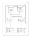
図1は、本実施の形態に係る通信システムの構成を示すブロック図である。本実施の形態に係る通信システムは、車両1に搭載されたゲートウェイ(車載通信装置)2に、ECU(他の車載装置)3,4がそれぞれ通信線を介して接続された構成である。ただし、車両1に搭載されるECUの数、通信線の数、及び、各通信線に接続されるECUの数等は、一例であって、これに限るものではない。
FIG. 1 is a block diagram showing a configuration of a communication system according to the present embodiment. The communication system according to the present embodiment has a configuration in which ECUs (other in-vehicle devices) 3 and 4 are connected to a gateway (vehicle-mounted communication device) 2 mounted on the
本実施の形態においてECU3は、ユーザの操作を受け付ける操作部3aを備えている。操作部3aは、例えばスイッチ、レバー又はタッチパネル等の入力デバイスを用いてユーザの操作を受け付ける。また、ECU4は種々の画像を表示する表示部4aを備えている。表示部4aは、例えば液晶ディスプレイを用いて構成される。本実施の形態に係る通信システムは、ECU3が操作部3aにてユーザの操作を受け付けて操作情報を含むメッセージをゲートウェイ2へ送信し、ゲートウェイ2がECU3から受信したメッセージをECU4へ送信し、このメッセージを受信したECU4が操作情報に応じた表示を表示部4aにて行う。本通信システムは、例えばユーザが車両1のイグニッションスイッチをオンする操作を行った場合に、車両1の運転席周辺に設けられた表示部4aに情報表示を行うシステムに適用できる。
In the present embodiment, the
ゲートウェイ2は、ECU3及びECU4の間のメッセージ送受信を中継する処理を行う。本実施の形態に係るゲートウェイ2は、メインマイコン(マイクロコントローラ)10、サブマイコン20及び通信IC(Integrated Circuit)30,40等を備えて構成されている。マイコンは、例えばプロセッサ、メモリ及び通信ユニット等が1つのICとして構成されたものであり、予め記憶したプログラムを実行することによって種々の演算処理及び制御処理等を行うことができる。本実施の形態に係るゲートウェイ2はメインマイコン(第1処理部)10及びサブマイコン(第2処理部)20の2つのマイコンを備えている。
The
通信IC(通信部)30,40は、ゲートウェイ2の回路内で用いられるデジタル信号と、通信線を介して送受信される信号とを相互に変換するICである。通信IC30,40は、メインマイコン10又はサブマイコン20からデジタル信号として与えられた送信メッセージを電気信号に変換して通信線へ出力する。また通信IC30,40は、通信線上の電気信号をサンプリングして取得し、デジタル信号として取得した受信メッセージをメインマイコン10及びサブマイコン20へ与える。メインマイコン10及びサブマイコン20は、共に通信IC30,40に接続されており、通信IC30,40を介してECU3,4との通信を行うことができる。
The communication ICs (communication units) 30 and 40 are ICs that mutually convert a digital signal used in the circuit of the
また本実施の形態に係るゲートウェイ2が備える2つのマイコンには、全く同じ2つのマイコンを用いるのではなく、構成が異なる2つのマイコンが用いられている。例えば、メインマイコン10が有するメモリの容量は、サブマイコン20のメモリの容量より多い。ただし、両マイコンのプロセッサの処理速度などの性能は同じであってもよい。メインマイコン10が実行するプログラムは、サブマイコン20が実行するプログラムと比較して、プログラムサイズが大きく、高機能且つ多機能である。
Further, as the two microcomputers included in the
例えば車両1のイグニッションスイッチがオフ状態である場合、車両1に搭載されたゲートウェイ2及びECU3,4は電源オフ状態又はスタンバイ状態等の処理を行わない状態となる。その後、例えばイグニッションスイッチがオン状態に切り替えられるなどのタイミングで、ゲートウェイ2及びECU3,4は起動し、処理を開始する。本実施の形態においては、操作部3aに対するユーザの操作がなされた場合にECU3が起動し、初期化処理を完了したECU3がゲートウェイ2との通信を行うことでゲートウェイ2が起動し、更にゲートウェイ2がECU4との通信を行うことでECU4が起動する。即ち本通信システムでは、ECU3、ゲートウェイ2、ECU4の順に起動が行われる。
For example, when the ignition switch of the
動作していない状態から起動されたマイコンは、自身が有するハードウェア資源の起動及び動作検証、レジスタなどの一時記憶の初期化、メモリからのプログラム及びデータの読み出し、又は、通信のセキュリティに関する設定処理等を初期化処理として実行する。本実施の形態において、メモリの容量が少なくプログラムサイズが小さいサブマイコン20は起動から初期化処理の完了までに要する時間が短く、メモリの容量が多くプログラムサイズが大きいメインマイコン10は起動から初期化処理の完了までに要する時間が長い。
A microcomputer started from a non-operating state starts and verifies its own hardware resources, initializes temporary storage such as registers, reads programs and data from memory, or performs setting processing related to communication security. Etc. are executed as initialization processing. In the present embodiment, the sub-microcomputer 20 having a small memory capacity and a small program size requires a short time from startup to the completion of the initialization process, and the
本実施の形態に係るゲートウェイ2では、初期化処理を先に完了するサブマイコン20が、初期化処理を終えた後にECU4との通信を行うことでECU4を起動する。メインマイコン10が初期化処理を行っている間に、ECU4は並行して初期化処理を開始することができる。これにより、メインマイコン10がECU4を起動する場合と比較して、ECU4が初期化処理を完了するタイミングを早めることができる。
In the
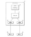
図2は、本実施の形態に係るメインマイコン10の構成を示すブロック図である。本実施の形態に係るゲートウェイ2のメインマイコン10は、プロセッサ11、メモリ12及び通信部13,14等を備えて構成されている。プロセッサ11は、メモリ12に記憶されたプログラムを読み出して実行することにより、種々の演算処理を行う演算処理装置である。メモリ12は、EEPROM(Electrically Erasable Programmable Read Only Memory)又はフラッシュメモリ等の不揮発性のメモリ素子を用いて構成され、プロセッサ11が実行する各種のプログラム及びこのプログラムを実行するために必要なデータ等を記憶する。
FIG. 2 is a block diagram showing a configuration of the
通信部13,14は、例えばCAN又はイーサネット等の通信規格に基づくメッセージの送受信を行う。通信部13,14は、ゲートウェイ2の回路基板上の配線を介して、通信IC30,40にそれぞれ接続されている。通信部13,14は、通信IC30,40及び通信線を介して、ECU3,4とそれぞれ通信を行うことができる。通信部13,14は、プロセッサ11から与えられたメッセージをデジタル信号として通信IC30,40へ出力し、これにより通信IC30,40からECU3,4へメッセージが送信される。また通信部13,14は、通信IC30,40から与えられるデジタル信号を取得することによりECU3,4からのメッセージを受信し、受信したメッセージをプロセッサ11へ与える。
The
図3は、本実施の形態に係るサブマイコン20の構成を示すブロック図である。本実施の形態に係るゲートウェイ2のサブマイコン20は、プロセッサ21、メモリ22及び通信部23,24等を備えて構成されている。プロセッサ21は、メモリ22に記憶されたプログラムを読み出して実行することにより、種々の演算処理を行う演算処理装置である。メモリ22は、EEPROM又はフラッシュメモリ等の不揮発性のメモリ素子を用いて構成され、プロセッサ21が実行する各種のプログラム及びこのプログラムを実行するために必要なデータ等を記憶する。
FIG. 3 is a block diagram showing the configuration of the sub-microcomputer 20 according to the present embodiment. The sub-microcomputer 20 of the
通信部23,24は、例えばCAN又はイーサネット等の通信規格に基づくメッセージの送受信を行う。通信部23,24は、ゲートウェイ2の回路基板上の配線を介して、通信IC30,40にそれぞれ接続されている。通信部23,24は、通信IC30,40及び通信線を介して、ECU3,4とそれぞれ通信を行うことができる。通信部23,24は、プロセッサ21から与えられたメッセージをデジタル信号として通信IC30,40へ出力し、これにより通信IC30,40からECU3,4へメッセージが送信される。また通信部23,24は、通信IC30,40から与えられるデジタル信号を取得することによりECU3,4からのメッセージを受信し、受信したメッセージをプロセッサ21へ与える。
The
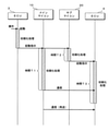
図4は、本実施の形態に係る通信システムの各装置が行う起動時の処理を説明するためのタイミングチャートである。図示の例では、ECU3、ゲートウェイ2、ECU4の順で装置が起動される。例えばECU3は、操作部3aに対するユーザの操作を受け付けた場合に起動し、初期化処理を開始する。ECU3は、初期化処理の完了後に、ゲートウェイ2に対して起動指示を送信する。なおECU3からゲートウェイ2へ送信する起動指示は、どのようなメッセージの送信であってもよい。
FIG. 4 is a timing chart for explaining the start-up processing performed by each device of the communication system according to the present embodiment. In the illustrated example, the apparatus is activated in the order of
ECU3からゲートウェイ2への起動指示は、ゲートウェイ2のメインマイコン10及びサブマイコン20の両方へ与えられる。この起動指示に応じてメインマイコン10及びサブマイコン20は共に起動し、初期化処理を開始する。ここで、メインマイコン10が起動から初期化処理の完了までに要する時間は、サブマイコン20が起動から初期化処理の完了までに要する時間より長いものとする。即ち、メインマイコン10の初期化処理に要する時間をT1とし、サブマイコン20の初期化処理に要する時間をT2とすると、時間T1>時間T2の関係が成立する。
The activation instruction from the
時間T2で初期化処理を終えたサブマイコン20は、ECU4に対して起動指示を送信する。なおサブマイコン20からECU4へ送信する起動指示は、どのようなメッセージの送信であってもよい。ECU4は、どのようなメッセージであっても、ゲートウェイ2からのメッセージを受信することによって起動し、初期化処理を開始する。ここで、ECU4の初期化処理に要する時間をT3とする。ECU4の初期化処理は、ゲートウェイ2のメインマイコン10の初期化処理と並行して行われ得る。
The sub-microcomputer 20 that has completed the initialization process at time T2 transmits a start instruction to the
時間T1で初期化処理を終えたメインマイコン10は、メッセージ中継などの通常処理を開始し、例えばECU4へのメッセージ送信などの通信処理を行う。このときにECU4の初期化処理が終了していなければ、メインマイコン10はECU4からの応答のメッセージは得られない。このような場合、メインマイコン10は、例えば所定時間の経過後にメッセージを再送信すればよい。
The
図示の例において、ECU3がゲートウェイ2へ起動指示を与えてからECU4の初期化処理が完了するまでの時間は(T2+T3)である。もし、サブマイコン20がECU4への起動指示を行わない構成であれば、メインマイコン10が初期化処理の完了後に送信するメッセージによりECU4が起動し、ECU4の初期化処理が開始されることとなる。この場合、ECU3がゲートウェイ2へ起動指示を与えてからECU4の初期化処理が完了するまでの時間は(T1+T3)であり、時間(T1+T3)>時間(T2+T3)の関係が成立する。即ち、サブマイコン20がECU4への起動指示を与える構成とすることにより、通信システム全体として初期化処理が完了するまでの時間を短縮することができる。
In the illustrated example, the time from when the
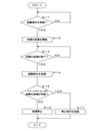
図5は、本実施の形態に係るサブマイコン20が行う処理の手順を示すフローチャートである。本実施の形態に係るサブマイコン20のプロセッサ21は、通信部23にてECU3からの起動指示を受信したか否かを判定する(ステップS1)。起動指示を受信していない場合(S1:NO)、プロセッサ21は、起動指示を受信するまで待機する。起動指示を受信した場合(S1:YES)、プロセッサ21は、初期化処理を開始する(ステップS2)。
FIG. 5 is a flowchart showing a procedure of processing performed by the sub-microcomputer 20 according to the present embodiment. The
その後、プロセッサ21は、初期化処理が終了したか否かを判定する(ステップS3)。初期化処理が終了していない場合(S3:NO)、プロセッサ21は、初期化処理を継続して行う。初期化処理が終了した場合(S3:YES)、プロセッサ21は、通信部24を介してECU4に対する起動指示を送信する(ステップS4)。必要な起動指示を送信し終えた後、プロセッサ21は処理を停止し(ステップS5)、処理を終える。
After that, the
以上の構成の本実施の形態に係るゲートウェイ2は、メインマイコン10及びサブマイコン20の2つのマイコンを備える。メインマイコン10及びサブマイコン20は、起動された後に初期化処理を開始し、初期化処理の完了後に通信などの処理を行うことができる。サブマイコン20は、メインマイコン10よりも起動から初期化処理の完了までに要する時間が短いものを用いる。サブマイコン20は、自身の初期化処理を完了した後、メインマイコン10の初期化処理が完了していなくても、ECU4に対して起動指示を送信する。これにより、メインマイコン10の初期化処理の完了を待つことなくゲートウェイ2はECU4へ起動指示を送信することができる。ECU4はより早いタイミングで初期化処理を開始することができ、より早いタイミングで初期化処理を完了することができる。よって、通信システム全体として、起動から初期化完了までに要する時間を短縮することができる。
The
また本実施の形態に係る通信システムでは、操作部3aに対するユーザの操作を受け付けたことによりECU3がゲートウェイ2のメインマイコン10及びサブマイコン20へ起動指示を与え、この起動指示に応じてメインマイコン10及びサブマイコン20が共に初期化処理を開始する。メインマイコン10の起動に対して遅滞なくサブマイコン20が起動して初期化処理を開始することにより、初期化処理に要する時間が短いサブマイコン20が確実にメインマイコン10より先に初期化処理を完了することができ、ECU4への起動指示を送信することができる。
Further, in the communication system according to the present embodiment, the
また本実施の形態に係るサブマイコン20は、ECU4への起動指示を送信した後に処理を停止する。サブマイコン20が処理を停止することで、サブマイコン20による電力消費を低減でき、ゲートウェイ2の電力消費を低減することができる。またサブマイコン20が起動指示の送信以外の処理を行わないことにより、サブマイコン20のハードウェア及びソフトウェアの規模を小さくすることができ、サブマイコン20の初期化処理をより短時間で完了させることが可能となる。
Further, the sub-microcomputer 20 according to the present embodiment stops processing after transmitting a start instruction to the
なお本実施の形態においては、ゲートウェイ2及びECU3,4が車両1に搭載されるものとしたが、これに限るものではなく、本技術は車載以外の通信装置にも適用可能である。ゲートウェイ2が備える処理部をマイコンとしたが、これに限るものではなく、マイコン以外の種々の処理部であってよい。またゲートウェイ2及びECU3,4を含む通信システムがECU3の操作部3aに対するユーザの操作に応じて起動する構成としたが、これに限るものではなく、ユーザ操作以外の要因で通信システムが起動する構成であってよい。操作部3aは車両1のイグニッションスイッチに限らず、その他の種々のスイッチ又はレバー等であってよい。またサブマイコン20は、メインマイコン10と比較して例えばメモリ容量が少ないなど規模の小さいマイコンを用いる構成としたが、これに限るものではなく、メインマイコン10及びサブマイコン20を同構成のマイコンとし、サブマイコン20が実行するプログラムサイズがメインマイコン10のプログラムサイズより小さい構成としてもよい。またサブマイコン20は、ECU4への起動指示を送信した後に処理を停止する構成としたが、これに限るものではなく、起動指示の送信後に他の処理を行ってもよい。
In the present embodiment, the
(変形例)
変形例に係るゲートウェイ2のサブマイコン20は、初期化処理を完了してECU4への起動指示を送信した後に処理を停止せず、メインマイコン10の初期化処理が異常なく完了したか否かを監視する処理を行う。変形例に係るサブマイコン20は、例えばメインマイコン10及び通信IC30,40の間で授受される情報を監視し、メインマイコン10が初期化処理の完了後にECU4へ送信すべきメッセージが正常に送信されたかを判定する。このメッセージが正常に送信された場合、サブマイコン20はメインマイコン10の初期化処理が正常に完了したと判断する。メインマイコン10の初期化処理が完了したと判断した場合、サブマイコン20は、処理を終了してよい。
(Modification example)
The sub-microcomputer 20 of the
これに対して、例えば初期化処理に要する時間T1又はこれより大きな時間が経過してもメインマイコン10からECU4へのメッセージが送信されない場合、サブマイコン20はメインマイコン10が初期化処理に失敗したと判断する。メインマイコン10の初期化処理が失敗した場合、サブマイコン20は、起動指示を与えたECU4に対して、処理を停止する指示を与える。これにより、ゲートウェイ2のメインマイコン10が本来の処理を行うことができない状況で、ECU4が処理を行うことを防止できる。
On the other hand, for example, when the message from the
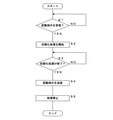
図6は、変形例に係るサブマイコン20が行う処理の手順を示すフローチャートである。変形例に係るサブマイコン20のプロセッサ21は、通信部23を介してECU3からの起動指示を受信したか否かを判定する(ステップS11)。起動指示を受信していない場合(S11:NO)、プロセッサ21は、起動指示を受信するまで待機する。起動指示を受信した場合(S11:YES)、プロセッサ21は、初期化処理を開始する(ステップS12)。
FIG. 6 is a flowchart showing a procedure of processing performed by the sub-microcomputer 20 according to the modified example. The
その後、プロセッサ21は、初期化処理が終了したか否かを判定する(ステップS13)。初期化処理が終了していない場合(S13:NO)、プロセッサ21は、初期化処理を継続して行う。初期化処理が終了した場合(S13:YES)、プロセッサ21は、通信部24を介してECU4に対する起動指示を送信する(ステップS14)。
After that, the
必要な起動指示を送信し終えた後、プロセッサ21は、メインマイコン10がECU4へ送信すべきメッセージが送信されたか否かを監視することによって、メインマイコン10の初期化処理が失敗したか否かを判定する(ステップS15)。メインマイコン10の初期化処理が失敗していない場合(S15:NO)、即ちメインマイコン10の初期化処理を完了した場合、サブマイコン20は処理を停止し(ステップS16)、処理を終える。メインマイコン10の初期化処理が失敗した場合(S15:YES)、サブマイコン20は、通信部24を介してECU4に対する停止指示を送信し(ステップS17)、処理を終了する。
After the necessary start instructions have been transmitted, the
以上の構成の本変形例に係るゲートウェイ2は、先に初期化処理を終えたサブマイコン20がメインマイコン10の初期化処理の正否を判定する。メインマイコン10の初期化処理が失敗した場合、サブマイコン20は起動指示を送信したECU4に対して動作を停止する指示を送信する。これにより、メインマイコン10の初期化処理の完了前に起動したECU4が、メインマイコン10の初期化処理が失敗したにもかかわらず動作し続けることを防止できる。
In the
なお本変形例では、メインマイコン10がECU4へのメッセージ送信を行ったか否かに応じて、サブマイコン20がメインマイコン10の初期化処理の正否を判定する構成としたが、これに限るものではない。例えば、メインマイコン10がサブマイコン20に対して初期化処理の完了を通知する信号を直接的に出力する構成とし、この通知の有無に応じてサブマイコン20がメインマイコン10の初期化処理の正否を判定してもよい。また例えば、メインマイコン10及びサブマイコン20が直接的に通信を行う構成とし、サブマイコン20がメインマイコン10に初期化処理が完了したか否かを問い合わせ、この問い合わせに対する応答に基づいてサブマイコン20がメインマイコン10の初期化処理の正否を判定してもよい。
In this modification, the sub-microcomputer 20 determines whether the initialization process of the
今回開示された実施形態はすべての点で例示であって、制限的なものではないと考えられるべきである。本発明の範囲は、上記した意味ではなく、特許請求の範囲によって示され、特許請求の範囲と均等の意味及び範囲内でのすべての変更が含まれることが意図される。 The embodiments disclosed this time should be considered to be exemplary in all respects and not restrictive. The scope of the present invention is indicated by the scope of claims, not the above-mentioned meaning, and is intended to include all modifications within the meaning and scope equivalent to the scope of claims.
1 車両
2 ゲートウェイ(車載通信装置)
3 ECU
3a 操作部
4 ECU(他の車載装置)
4a 表示部
10 メインマイコン(第1処理部)
11 プロセッサ
12 メモリ
13,14 通信部
20 サブマイコン(第2処理部)
21 プロセッサ
22 メモリ
23,24 通信部
30,40 通信IC(通信部)
1
3 ECU
11
21
Claims (4)
前記第1処理部よりも起動から初期化処理の完了までに要する時間が短い第2処理部と、
通信線を介して他の車載装置が接続され、前記第1処理部及び前記第2処理部の制御に応じて前記他の車載装置との通信を行う通信部と
を備え、
前記第2処理部は、
自身の初期化処理の完了後に、前記通信部を介して前記他の車載装置を起動する指示を送信し、
前記第1処理部の初期化処理が失敗した場合に、前記通信部を介して前記他の車載装置に動作を停止する指示を送信する、
車載通信装置。 The first processing unit that performs its own initialization processing by starting,
The second processing unit, which takes less time from the start to the completion of the initialization process than the first processing unit,
Another vehicle-mounted device is connected via a communication line, and includes a communication unit that communicates with the other vehicle-mounted device according to the control of the first processing unit and the second processing unit.
The second processing unit is
After the initialization process of itself is completed, an instruction to start the other in-vehicle device is transmitted via the communication unit, and the instruction is transmitted.
When the initialization process of the first processing unit fails, an instruction to stop the operation is transmitted to the other in-vehicle device via the communication unit.
In-vehicle communication device.
前記車載通信装置が、起動により自身の初期化処理を行う第1処理部と、前記第1処理部よりも起動から初期化処理の完了までに要する時間が短い第2処理部とを備え、
前記第2処理部が、
自身の初期化処理の完了後に、前記通信部を介して前記他の車載装置を起動する指示を送信し、
前記第1処理部の初期化処理が失敗した場合に、前記通信部を介して前記他の車載装置に動作を停止する指示を送信する、
車載装置起動方法。 An in-vehicle communication device including a communication unit that is connected to another in-vehicle device via a communication line and communicates with the other in-vehicle device is an in-vehicle device activation method for activating the other in-vehicle device.
The in-vehicle communication device includes a first processing unit that performs its own initialization processing by activation, and a second processing unit that takes less time from activation to completion of the initialization processing than the first processing unit.
The second processing unit
After the initialization process of itself is completed, an instruction to start the other in-vehicle device is transmitted via the communication unit, and the instruction is transmitted.
When the initialization process of the first processing unit fails, an instruction to stop the operation is transmitted to the other in-vehicle device via the communication unit.
How to start the in-vehicle device.
Priority Applications (4)
| Application Number | Priority Date | Filing Date | Title |
|---|---|---|---|
| JP2018110550A JP6996429B2 (en) | 2018-06-08 | 2018-06-08 | In-vehicle communication device and in-vehicle device activation method |
| CN201980034140.1A CN112154414A (en) | 2018-06-08 | 2019-05-27 | In-vehicle communication device and in-vehicle device activation method |
| PCT/JP2019/020911 WO2019235285A1 (en) | 2018-06-08 | 2019-05-27 | In-vehicle communication device and in-vehicle device start-up method |
| US16/973,121 US11840181B2 (en) | 2018-06-08 | 2019-05-27 | In-vehicle communication device and method for starting up in-vehicle device |
Applications Claiming Priority (1)
| Application Number | Priority Date | Filing Date | Title |
|---|---|---|---|
| JP2018110550A JP6996429B2 (en) | 2018-06-08 | 2018-06-08 | In-vehicle communication device and in-vehicle device activation method |
Publications (2)
| Publication Number | Publication Date |
|---|---|
| JP2019212230A JP2019212230A (en) | 2019-12-12 |
| JP6996429B2 true JP6996429B2 (en) | 2022-01-17 |
Family
ID=68769481
Family Applications (1)
| Application Number | Title | Priority Date | Filing Date |
|---|---|---|---|
| JP2018110550A Active JP6996429B2 (en) | 2018-06-08 | 2018-06-08 | In-vehicle communication device and in-vehicle device activation method |
Country Status (4)
| Country | Link |
|---|---|
| US (1) | US11840181B2 (en) |
| JP (1) | JP6996429B2 (en) |
| CN (1) | CN112154414A (en) |
| WO (1) | WO2019235285A1 (en) |
Families Citing this family (4)
| Publication number | Priority date | Publication date | Assignee | Title |
|---|---|---|---|---|
| JP7388035B2 (en) * | 2019-07-31 | 2023-11-29 | マツダ株式会社 | Vehicle control system and vehicle control system design method |
| US12143241B2 (en) | 2021-01-27 | 2024-11-12 | Autonetworks Technologies, Ltd. | Vehicle-mounted apparatus and a method for relaying |
| EP4353538A1 (en) * | 2022-10-10 | 2024-04-17 | Aptiv Technologies Limited | A control system for a vehicle and method of implementing same |
| CN116176461B (en) * | 2023-04-28 | 2023-08-11 | 亿咖通(湖北)技术有限公司 | Display method, system, electronic device and storage medium of vehicle instrument interface |
Citations (4)
| Publication number | Priority date | Publication date | Assignee | Title |
|---|---|---|---|---|
| US20080077786A1 (en) | 2006-09-27 | 2008-03-27 | Pierce James R | Rapid-boot computing device with dual operating systems |
| JP2008287317A (en) | 2007-05-15 | 2008-11-27 | Alpine Electronics Inc | Information processor and system startup method |
| JP2009258986A (en) | 2008-04-16 | 2009-11-05 | Fujitsu Ten Ltd | Content-reproducing device and electronic equipment |
| JP2016179801A (en) | 2015-03-25 | 2016-10-13 | 株式会社デンソー | In-vehicle system |
Family Cites Families (6)
| Publication number | Priority date | Publication date | Assignee | Title |
|---|---|---|---|---|
| JP4266358B2 (en) * | 2004-04-12 | 2009-05-20 | 三菱電機株式会社 | In-vehicle electronic control unit |
| JP5032866B2 (en) * | 2007-03-15 | 2012-09-26 | 株式会社オートネットワーク技術研究所 | Electronic control unit |
| JP2015053633A (en) | 2013-09-09 | 2015-03-19 | 株式会社オートネットワーク技術研究所 | Communications system |
| KR101490409B1 (en) * | 2014-02-13 | 2015-02-05 | 현대자동차주식회사 | Control unit for in-vehicle ethernet and method for controlling therof |
| JP6515915B2 (en) * | 2016-12-26 | 2019-05-22 | トヨタ自動車株式会社 | In-vehicle network system |
| US11163303B2 (en) * | 2018-02-13 | 2021-11-02 | Nvidia Corporation | Sharing sensor data between multiple controllers to support vehicle operations |
-
2018
- 2018-06-08 JP JP2018110550A patent/JP6996429B2/en active Active
-
2019
- 2019-05-27 US US16/973,121 patent/US11840181B2/en active Active
- 2019-05-27 CN CN201980034140.1A patent/CN112154414A/en active Pending
- 2019-05-27 WO PCT/JP2019/020911 patent/WO2019235285A1/en not_active Ceased
Patent Citations (4)
| Publication number | Priority date | Publication date | Assignee | Title |
|---|---|---|---|---|
| US20080077786A1 (en) | 2006-09-27 | 2008-03-27 | Pierce James R | Rapid-boot computing device with dual operating systems |
| JP2008287317A (en) | 2007-05-15 | 2008-11-27 | Alpine Electronics Inc | Information processor and system startup method |
| JP2009258986A (en) | 2008-04-16 | 2009-11-05 | Fujitsu Ten Ltd | Content-reproducing device and electronic equipment |
| JP2016179801A (en) | 2015-03-25 | 2016-10-13 | 株式会社デンソー | In-vehicle system |
Also Published As
| Publication number | Publication date |
|---|---|
| WO2019235285A1 (en) | 2019-12-12 |
| US20210253045A1 (en) | 2021-08-19 |
| CN112154414A (en) | 2020-12-29 |
| US11840181B2 (en) | 2023-12-12 |
| JP2019212230A (en) | 2019-12-12 |
Similar Documents
| Publication | Publication Date | Title |
|---|---|---|
| JP6996429B2 (en) | In-vehicle communication device and in-vehicle device activation method | |
| CN108427609B (en) | Controller and control program update method | |
| CN110753905A (en) | Control device, control method, and computer program | |
| KR102109125B1 (en) | Method for managing state of ECU in vehicle based on automotive open system architecture | |
| WO2019187535A1 (en) | Control device, control method, and computer program | |
| US11650794B2 (en) | Electronic control apparatus | |
| CN102081526B (en) | Basic Input/Output System Architecture | |
| US10296322B2 (en) | Controller and control program updating method | |
| CN113824620A (en) | Partition switching method, device, vehicle and storage medium | |
| JP4013592B2 (en) | Vehicle communication system | |
| JP3633406B2 (en) | EEPROM writing device | |
| US5321830A (en) | Reset method when adaptor module is faulty and computer system executing same | |
| KR101744998B1 (en) | Re-programming control module and re-programming system and method using the re-programming control module | |
| CN115668872B (en) | Vehicle-mounted device, vehicle-mounted communication system, and communication control method | |
| CN116633780B (en) | Vehicle gateway upgrade method, device, vehicle and storage medium | |
| US20250132979A1 (en) | Communication control device, vehicle, communication control method, and communication control program | |
| US20250158887A1 (en) | Communication control device, vehicle, communication control method, and communication control program | |
| JP6573052B1 (en) | Control device, control method, and computer program | |
| JP7771698B2 (en) | In-vehicle device, connection switching method, and connection switching program | |
| JP2009288953A (en) | Electronic control device | |
| JP5128194B2 (en) | Relay connection unit | |
| JP3452187B2 (en) | Communication initialization method for failure diagnosis device | |
| CN118805364A (en) | Communication control device, vehicle, communication control method, and communication control program | |
| CN105677376A (en) | Bootstrap program transmission method, embedded system and bootstrap program transmission system | |
| JPH1021202A (en) | Network connection system of duplex computer |
Legal Events
| Date | Code | Title | Description |
|---|---|---|---|
| A621 | Written request for application examination |
Free format text: JAPANESE INTERMEDIATE CODE: A621 Effective date: 20200930 |
|
| A131 | Notification of reasons for refusal |
Free format text: JAPANESE INTERMEDIATE CODE: A131 Effective date: 20210921 |
|
| A521 | Request for written amendment filed |
Free format text: JAPANESE INTERMEDIATE CODE: A523 Effective date: 20211029 |
|
| TRDD | Decision of grant or rejection written | ||
| A01 | Written decision to grant a patent or to grant a registration (utility model) |
Free format text: JAPANESE INTERMEDIATE CODE: A01 Effective date: 20211116 |
|
| A61 | First payment of annual fees (during grant procedure) |
Free format text: JAPANESE INTERMEDIATE CODE: A61 Effective date: 20211129 |
|
| R150 | Certificate of patent or registration of utility model |
Ref document number: 6996429 Country of ref document: JP Free format text: JAPANESE INTERMEDIATE CODE: R150 |
|
| R250 | Receipt of annual fees |
Free format text: JAPANESE INTERMEDIATE CODE: R250 |
|
| R250 | Receipt of annual fees |
Free format text: JAPANESE INTERMEDIATE CODE: R250 |