JP7388035B2 - Vehicle control system and vehicle control system design method - Google Patents
Vehicle control system and vehicle control system design method Download PDFInfo
- Publication number
- JP7388035B2 JP7388035B2 JP2019141119A JP2019141119A JP7388035B2 JP 7388035 B2 JP7388035 B2 JP 7388035B2 JP 2019141119 A JP2019141119 A JP 2019141119A JP 2019141119 A JP2019141119 A JP 2019141119A JP 7388035 B2 JP7388035 B2 JP 7388035B2
- Authority
- JP
- Japan
- Prior art keywords
- zone
- delay time
- ecu
- zone ecu
- signal
- Prior art date
- Legal status (The legal status is an assumption and is not a legal conclusion. Google has not performed a legal analysis and makes no representation as to the accuracy of the status listed.)
- Active
Links
- 238000000034 method Methods 0.000 title claims description 75
- 238000013461 design Methods 0.000 title claims description 20
- 238000012545 processing Methods 0.000 claims description 193
- 238000004891 communication Methods 0.000 claims description 177
- 230000004913 activation Effects 0.000 claims description 45
- 238000006243 chemical reaction Methods 0.000 description 66
- 230000005540 biological transmission Effects 0.000 description 45
- 230000008569 process Effects 0.000 description 39
- 230000002776 aggregation Effects 0.000 description 24
- 238000004220 aggregation Methods 0.000 description 24
- 238000001514 detection method Methods 0.000 description 16
- 238000010586 diagram Methods 0.000 description 15
- 238000005516 engineering process Methods 0.000 description 12
- 238000004364 calculation method Methods 0.000 description 10
- 230000007274 generation of a signal involved in cell-cell signaling Effects 0.000 description 9
- 238000005315 distribution function Methods 0.000 description 7
- 230000007246 mechanism Effects 0.000 description 4
- 230000008054 signal transmission Effects 0.000 description 4
- 238000004088 simulation Methods 0.000 description 4
- 230000008859 change Effects 0.000 description 3
- 239000000284 extract Substances 0.000 description 3
- 238000011084 recovery Methods 0.000 description 3
- 230000004044 response Effects 0.000 description 3
- 238000013473 artificial intelligence Methods 0.000 description 2
- 230000006399 behavior Effects 0.000 description 2
- 230000003247 decreasing effect Effects 0.000 description 2
- 238000000605 extraction Methods 0.000 description 2
- 238000009434 installation Methods 0.000 description 2
- 239000000203 mixture Substances 0.000 description 2
- 230000006641 stabilisation Effects 0.000 description 2
- 238000011105 stabilization Methods 0.000 description 2
- 101000849579 Arabidopsis thaliana 30S ribosomal protein S13, chloroplastic Proteins 0.000 description 1
- 230000001133 acceleration Effects 0.000 description 1
- 230000003213 activating effect Effects 0.000 description 1
- 230000001934 delay Effects 0.000 description 1
- 230000003111 delayed effect Effects 0.000 description 1
- 238000012938 design process Methods 0.000 description 1
- 238000011161 development Methods 0.000 description 1
- 238000004193 electrokinetic chromatography Methods 0.000 description 1
- 230000007613 environmental effect Effects 0.000 description 1
- 239000000446 fuel Substances 0.000 description 1
- 238000012986 modification Methods 0.000 description 1
- 230000004048 modification Effects 0.000 description 1
- 238000006467 substitution reaction Methods 0.000 description 1
- 230000002123 temporal effect Effects 0.000 description 1
Images


Classifications
-
- B—PERFORMING OPERATIONS; TRANSPORTING
- B60—VEHICLES IN GENERAL
- B60R—VEHICLES, VEHICLE FITTINGS, OR VEHICLE PARTS, NOT OTHERWISE PROVIDED FOR
- B60R16/00—Electric or fluid circuits specially adapted for vehicles and not otherwise provided for; Arrangement of elements of electric or fluid circuits specially adapted for vehicles and not otherwise provided for
- B60R16/02—Electric or fluid circuits specially adapted for vehicles and not otherwise provided for; Arrangement of elements of electric or fluid circuits specially adapted for vehicles and not otherwise provided for electric constitutive elements
- B60R16/023—Electric or fluid circuits specially adapted for vehicles and not otherwise provided for; Arrangement of elements of electric or fluid circuits specially adapted for vehicles and not otherwise provided for electric constitutive elements for transmission of signals between vehicle parts or subsystems
-
- H—ELECTRICITY
- H04—ELECTRIC COMMUNICATION TECHNIQUE
- H04L—TRANSMISSION OF DIGITAL INFORMATION, e.g. TELEGRAPHIC COMMUNICATION
- H04L12/00—Data switching networks
- H04L12/28—Data switching networks characterised by path configuration, e.g. LAN [Local Area Networks] or WAN [Wide Area Networks]
- H04L12/40—Bus networks
- H04L12/40006—Architecture of a communication node
- H04L12/40026—Details regarding a bus guardian
-
- G—PHYSICS
- G05—CONTROLLING; REGULATING
- G05B—CONTROL OR REGULATING SYSTEMS IN GENERAL; FUNCTIONAL ELEMENTS OF SUCH SYSTEMS; MONITORING OR TESTING ARRANGEMENTS FOR SUCH SYSTEMS OR ELEMENTS
- G05B19/00—Programme-control systems
- G05B19/02—Programme-control systems electric
- G05B19/04—Programme control other than numerical control, i.e. in sequence controllers or logic controllers
- G05B19/042—Programme control other than numerical control, i.e. in sequence controllers or logic controllers using digital processors
- G05B19/0423—Input/output
-
- H—ELECTRICITY
- H04—ELECTRIC COMMUNICATION TECHNIQUE
- H04L—TRANSMISSION OF DIGITAL INFORMATION, e.g. TELEGRAPHIC COMMUNICATION
- H04L12/00—Data switching networks
- H04L12/28—Data switching networks characterised by path configuration, e.g. LAN [Local Area Networks] or WAN [Wide Area Networks]
- H04L12/40—Bus networks
-
- H—ELECTRICITY
- H04—ELECTRIC COMMUNICATION TECHNIQUE
- H04L—TRANSMISSION OF DIGITAL INFORMATION, e.g. TELEGRAPHIC COMMUNICATION
- H04L65/00—Network arrangements, protocols or services for supporting real-time applications in data packet communication
- H04L65/40—Support for services or applications
-
- G—PHYSICS
- G05—CONTROLLING; REGULATING
- G05B—CONTROL OR REGULATING SYSTEMS IN GENERAL; FUNCTIONAL ELEMENTS OF SUCH SYSTEMS; MONITORING OR TESTING ARRANGEMENTS FOR SUCH SYSTEMS OR ELEMENTS
- G05B2219/00—Program-control systems
- G05B2219/20—Pc systems
- G05B2219/25—Pc structure of the system
- G05B2219/25257—Microcontroller
-
- H—ELECTRICITY
- H04—ELECTRIC COMMUNICATION TECHNIQUE
- H04L—TRANSMISSION OF DIGITAL INFORMATION, e.g. TELEGRAPHIC COMMUNICATION
- H04L12/00—Data switching networks
- H04L12/28—Data switching networks characterised by path configuration, e.g. LAN [Local Area Networks] or WAN [Wide Area Networks]
- H04L12/40—Bus networks
- H04L2012/40267—Bus for use in transportation systems
- H04L2012/40273—Bus for use in transportation systems the transportation system being a vehicle
Description
ここに開示された技術は、車両制御システム及び車両制御システムの設計方法に関する。 The technology disclosed herein relates to a vehicle control system and a method of designing a vehicle control system.
特許文献1には、車載機器の機能に応じて複数のドメインに区分けし、ドメイン毎にドメイン制御部を設け、複数のドメイン制御部を統合制御部で制御する技術が開示されている。特許文献1では、例えば、各機器制御部が、単一または複数のECUで実現されており、それらのECUが階層型のネットワークにより接続されている。
特許文献2には、車載ネットワークシステムにおいて、異なるネットワークのノード同士のデータ送受を中継するゲートウェイやネットワークハブ(HUB)を設ける技術が開示されている。 Patent Document 2 discloses a technology for providing a gateway or a network hub (HUB) that relays data transmission and reception between nodes of different networks in an in-vehicle network system.
ところで、昨今、自動運転システムをはじめとして、車内外の環境情報や運転者情報(以下、まとめて単に「車内外環境情報」という)等に応じて車両を制御する車両の自動化(一部自動化を含む)に関する技術開発が推進されている。一般に、車両の自動化技術では、カメラやセンサ等(以下、単に「センサ」という)により車内外環境情報(運転者の操作情報を含む)が取得され、取得された車内外環境情報を基に演算処理がされ、その演算結果を基に車両に搭載された各種のアクチュエータが制御される。そして、将来的には、上記の演算処理機能及び各アクチュエータの制御機能が、車両全体の動作を統括して管理するような中央演算装置に集約されていくことが想定される。 Incidentally, in recent years, automated driving systems and other vehicle automation (partial automation) that control vehicles according to environmental information inside and outside the vehicle and driver information (hereinafter collectively referred to as "vehicle and exterior environment information") have been introduced. technology development is being promoted. In general, in vehicle automation technology, information on the interior and exterior environments of the vehicle (including information on driver operations) is acquired using cameras, sensors, etc. (hereinafter simply referred to as "sensors"), and calculations are made based on the acquired environment information inside and outside the vehicle. Processing is performed, and various actuators mounted on the vehicle are controlled based on the calculation results. In the future, it is assumed that the above-mentioned arithmetic processing functions and control functions of each actuator will be integrated into a central processing unit that will centrally manage the operation of the entire vehicle.
一方で、上記のように機能が集約された中央演算装置に対して、各センサや各アクチュエータをそれぞれ直接接続するのは、信号配線が膨大になるため現実的ではない。 On the other hand, it is not practical to directly connect each sensor and each actuator to a central processing unit with integrated functions as described above because it requires an enormous amount of signal wiring.
そこで、特許文献2のように、ネットワークハブ装置やゲートウェイ装置として機能するようなECU(Electronic Control Unit)を設け、そのECUを介して通信させるような車載ネットワークが構築されることが想定される。すなわち、ECUをデイジーチェーン接続することが想定される。さらに、基幹ネットワークは、イーサネット(登録商標)のような高速インターフェースで構成される一方で、末端部分等において従前のCANインターフェースが残ることが想定される。 Therefore, as in Patent Document 2, it is assumed that an in-vehicle network will be constructed in which an ECU (Electronic Control Unit) that functions as a network hub device or a gateway device is provided and communication is performed via the ECU. That is, it is assumed that the ECUs are connected in a daisy chain. Furthermore, while the backbone network is configured with a high-speed interface such as Ethernet (registered trademark), it is assumed that the conventional CAN interface will remain at the end portions.
そうすると、データを送受信する際に待ち時間が発生したり、プロトコル変換のためのプロトコル変換時間発生することが想定される。また、例えば、車両の停車中等において、消費電力の削減を目的として、各ECUをスリープ状態または電源OFF状態にすることがある。車載ネットワークでは、車両の各部に設置されたセンサやスイッチ等に基づいて各機能を起動させる場合があり、その場合に、デイジーチェーン接続されたネットワーク構成において、起動信号の伝搬による起動遅れ時間が問題となる場合がある。 In this case, it is assumed that waiting time will occur when transmitting and receiving data, and protocol conversion time will occur for protocol conversion. Further, for example, when the vehicle is stopped, each ECU may be put into a sleep state or a power OFF state for the purpose of reducing power consumption. In an in-vehicle network, each function may be activated based on sensors, switches, etc. installed in various parts of the vehicle. In this case, in a daisy-chained network configuration, startup delay time due to the propagation of the activation signal becomes a problem. In some cases,
ここに開示された技術は、斯かる点に鑑みてなされたものであり、その目的とするとこは、アクチュエータの制御機能を中央演算装置に取り込むための設計方法を提供することにある。 The technology disclosed herein has been developed in view of this point, and its purpose is to provide a design method for incorporating the actuator control function into a central processing unit.
前記課題を解決するために、ここに開示された技術では、車両の所定のゾーン毎に配置された複数のゾーンECUと、当該複数のゾーンECUを統括する中央演算装置とが設けられ、前記車両に設置された情報取得手段からの起動信号にしたがって当該車両に設置された車載デバイスを動作させるための車両制御システムの設計方法を対象として、前記中央演算装置と、前記複数のゾーンECUとをデイジーチェーン状に接続して基幹ネットワークを構築するステップと、前記複数のゾーンECUのうちの所定のゾーンECUから前記中央演算装置に向かうネットワークが順次起動されて前記中央演算装置が起動するまでの第1起動時間を算出するステップと、前記中央演算装置から前記複数のゾーンECUのうちの所定のゾーンECUに向かうネットワークが順次起動されて当該ゾーンECUが起動するまでの第2起動時間を算出するステップと、前記第1起動時間と前記第2起動時間との合計時間が所定の遅延時間未満になるように、前記複数のゾーンECUの中から前記情報取得手段の接続先及び前記車載デバイスの接続先を決定するステップとを備える、ことを特徴とする。 In order to solve the above problem, the technology disclosed herein includes a plurality of zone ECUs disposed in each predetermined zone of a vehicle, and a central processing unit that controls the plurality of zone ECUs, and a central processing unit that controls the plurality of zone ECUs. In this method, the central processing unit and the plurality of zone ECUs are connected in a daisy-type manner, and the central processing unit and the plurality of zone ECUs are connected to each other. a step of connecting in a chain to construct a backbone network; and a first step of sequentially activating a network from a predetermined zone ECU among the plurality of zone ECUs to the central processing unit until the central processing unit is activated. a step of calculating a start-up time, and a step of calculating a second start-up time from the central processing unit to a predetermined zone ECU among the plurality of zone ECUs when a network is sequentially started up until the zone ECU starts up. , a connection destination of the information acquisition means and a connection destination of the in-vehicle device are selected from among the plurality of zone ECUs so that the total time of the first startup time and the second startup time is less than a predetermined delay time. and a step of determining.
また、ここに開示された技術では、車両の所定のゾーン毎に配置された複数のゾーンECUと、当該複数のゾーンECUを統括する中央演算装置とが設けられ、前記車両に設置された情報取得手段からの起動信号にしたがって当該車両に設置された車載デバイスを作動させるための車両制御システムの設計方法を対象として、前記中央演算装置と、前記複数のゾーンECUとをデイジーチェーン状に接続してネットワークを構築する方法として、前記複数のゾーンECUのうちの前記情報取得手段から起動信号を受信する第1ゾーンECUから前記中央演算装置に向かう第1ネットワークが順次起動されて前記中央演算装置が起動するまでの第1起動時間と、前記中央演算装置から前記複数のゾーンECUのうちの前記車載デバイスの制御信号を出力する第2ゾーンECUに向かう第2ネットワークが順次起動されて当該第2ゾーンECUが起動するまでの第2起動時間と、の合計時間が所定の遅延時間未満になるように、前記第1ネットワーク及び前記第2ネットワークのネットワーク経路を設定することを含む、ことを特徴とする。 Further, the technology disclosed herein includes a plurality of zone ECUs arranged in each predetermined zone of a vehicle, and a central processing unit that controls the plurality of zone ECUs, and an information acquisition unit installed in the vehicle. A method for designing a vehicle control system for operating an on-vehicle device installed in a vehicle according to a start signal from a means, the central processing unit and the plurality of zone ECUs are connected in a daisy chain. As a method for constructing a network, a first network from a first zone ECU that receives an activation signal from the information acquisition means among the plurality of zone ECUs toward the central processing unit is activated in sequence, and the central processing unit is activated. A second network leading from the central processing unit to a second zone ECU that outputs a control signal for the in-vehicle device among the plurality of zone ECUs is sequentially activated until the second zone ECU The present invention is characterized in that it includes setting network paths of the first network and the second network so that a total time of a second activation time until activation of the first network and a second activation time is less than a predetermined delay time.
車両の動作を統括する中央演算装置と、前記中央演算装置にデイジーチェーン状に接続された複数のゾーンECUとを備え、前記車両に設置された情報取得手段からの起動信号にしたがって当該車両に設置された車載デバイスを作動させるための車両制御システムを対象として、前記複数のゾーンECUは、前記情報取得手段が接続された第1ゾーンECUと、前記車載デバイスが接続された第2ゾーンECUとを含み、前記第1ゾーンECU及び前記第2ゾーンECUは、前記第1ゾーンECUが前記情報取得手段からの前記起動信号を受信し、前記第1ゾーンECUから前記中央演算装置に向かう第1ネットワークが順次起動されて前記中央演算装置が起動するまでの第1起動時間と、前記中央演算装置が起動されてから前記中央演算装置から前記第2ゾーンECUに向かう第2ネットワークが順次起動されて当該第2ゾーンECUが起動するまでの第2起動時間との合計時間が所定の遅延時間未満になるように、前記第1ゾーンECU及び前記第2ゾーンECUが設定された、ことを特徴とする。 A central processing unit that controls the operation of a vehicle, and a plurality of zone ECUs connected to the central processing unit in a daisy chain, and installed in the vehicle according to a start signal from an information acquisition means installed in the vehicle. The plurality of zone ECUs include a first zone ECU to which the information acquisition means is connected and a second zone ECU to which the in-vehicle device is connected. The first zone ECU and the second zone ECU are configured such that the first zone ECU receives the activation signal from the information acquisition means, and a first network from the first zone ECU to the central processing unit A first startup time from when the central processing unit is started up until the central processing unit is started up, and a second network from the central processing unit to the second zone ECU is started up sequentially from the central processing unit to the second zone ECU. The first zone ECU and the second zone ECU are set so that the total time including the second activation time until the two-zone ECU is activated is less than a predetermined delay time.
これらの態様によると、車載ネットワークにおいて、複数の通信プロトコルが混在し、かつ、互いに異なる通信プロトコルがデイジーチェーンで接続されるような複雑なネットワークシステムにおいて、起動遅れを考慮したネットワークを構成することができる。 According to these aspects, in an in-vehicle network, it is possible to configure a network that takes startup delays into account in a complex network system in which multiple communication protocols coexist and different communication protocols are connected in a daisy chain. can.
ここに開示された技術によると、アクチュエータの制御機能を中央演算装置に取り込むための設計方法が提供される。 According to the technology disclosed herein, a design method for incorporating an actuator control function into a central processing unit is provided.
以下、例示的な実施形態について、図面を参照しながら詳細に説明する。なお、本明細書では、車両に搭載されるセンサやアクチュエータ等の走行制御を司る装置類のことを、車載デバイス、または、単にデバイスという。 Hereinafter, exemplary embodiments will be described in detail with reference to the drawings. Note that in this specification, devices such as sensors and actuators mounted on a vehicle that control driving are referred to as in-vehicle devices or simply devices.
(実施形態1)
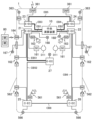
図1は車載ネットワークシステムの構成例を示す図である。図1の車載ネットワークシステムは、車両1に搭載されており、中央演算装置10と、複数のゾーンECU2とを備える。本実施形態の車載ネットワークシステムでは、車両1を複数(本実施形態では7つ)のゾーンに分け、各ゾーンにゾーンECU2が設けられる。なお、詳細は後述するが、各ゾーンECU2は、ネットワークを介して伝送される情報を中継する機能を有するネットワークハブ装置としての機能を有する。
(Embodiment 1)
FIG. 1 is a diagram showing an example of the configuration of an in-vehicle network system. The in-vehicle network system in FIG. 1 is installed in a
以下の説明において、車両1の左前部座席近傍の左ダッシュゾーンに配置されたゾーンECU2を第1ゾーンECU21、車両1の右前部座席近傍の右ダッシュゾーンに配置されたゾーンECU2を第2ゾーンECU22ということがある。車両1の左前側の左フロントゾーンに配置されたゾーンECU2を第3ゾーンECU23、車両1の右前側の右フロントゾーンに配置されたゾーンECU2を第4ゾーンECU24ということがある。車両1の左後側の左リアゾーンに配置されたゾーンECU2を第5ゾーンECU25といい、車両1の右後側の右リアゾーンに配置されたゾーンECU2を第6ゾーンECU26ということがある。車両1のセンターコンソール近傍のコンソールゾーンに配置されたゾーンECU2を第7ゾーンECU27ということがある。なお、各ゾーンECU21~27を区別しないときには、単にゾーンECU2という。また、ゾーンの数を増減させるときには、それに応じてゾーンECU2の個数も増減する。
In the following description, the zone ECU 2 arranged in the left dash zone near the left front seat of the
ゾーンECU2は、後述するスマートECU、スマートアクチュエータ、センサやアクチュエータ等の車載デバイスを接続することができるように構成されている。なお、本実施形態では、ゾーンECU2が、各ゾーンに設けられている例を示しているが、これに限定されず、例えば、ゾーンによらずに、特定の機能に対応する車載デバイスを接続するためのゾーンECUを設けてもよい。また、ゾーン内に複数のゾーンECUを設けてもよい。また、スマートECUがゾーンECUとしての機能を兼ねたり、ゾーンECUがスマートECUとしての機能を兼ねていてもよい。 The zone ECU 2 is configured to be able to connect in-vehicle devices such as a smart ECU, a smart actuator, a sensor, and an actuator, which will be described later. Although the present embodiment shows an example in which the zone ECU 2 is provided in each zone, the present invention is not limited to this, and for example, an in-vehicle device corresponding to a specific function may be connected regardless of the zone. A zone ECU may be provided for this purpose. Further, a plurality of zone ECUs may be provided within a zone. Further, the smart ECU may also function as a zone ECU, or the zone ECU may also function as a smart ECU.
図1において、第1ゾーンECU21、第2ゾーンECU22、第3ゾーンECU23、第4ゾーンECU24は、中央演算装置10との間で、イーサネット信号の送受信を行うイーサハブ装置(図1ではE-ECと表記している)としての機能を有する。中央演算装置10と第1ゾーンECU21との間はイーサネットケーブルEB1で接続され、中央演算装置10と第2ゾーンECU22との間はイーサネットケーブルEB2で接続されている。中央演算装置10と第3ゾーンECU23との間はイーサネットケーブルEB3で接続され、中央演算装置10と第4ゾーンECU24との間はイーサネットケーブルEB4で接続され、第3ゾーンECU23と第4ゾーンECU24との間はイーサネットケーブルEB5で接続されている。ここで、イーサネット信号はイーサネットプロトコルに準拠した信号である。同様に、後述するCAN信号はCANプロトコルに準拠した信号であり、CAN-FD信号はCAN-FDプロトコルに準拠した信号であり、LIN(Local Interconnect Network)信号はLINプロトコルに準拠した信号である。
In FIG. 1, a
図1において、第5ゾーンECU25、第6ゾーンECU26、第7ゾーンECU27は、中央演算装置10及び/または他のゾーンECU2との間で、CAN-FD(CAN with Flexible Data-Rate)信号またはCAN(Controller Area Network)信号の送受信を行うCANハブ装置(図1ではC-ECと表記している)としての機能を有する。第1ゾーンECU21と第5ゾーンECU25との間はCAN-FDケーブルCB5で接続され、第2ゾーンECU22と第6ゾーンECU26との間はCAN-FDケーブルCB6で接続され、第5ゾーンECU25と第6ゾーンECU26との間はCAN-FDケーブルCB8で接続されている。第1ゾーンECU21と第7ゾーンECU27との間はCAN-FDケーブルCB7で接続されている。
In FIG. 1, the
本実施形態では、中央演算装置10と各ゾーンECU2との間の信号伝送経路、及び、ゾーンECU2間の信号伝送経路で形成されるネットワークを「基幹ネットワーク」と呼ぶ。図1では、イーサネットケーブルEB1~EB5、及び、CAN-FDケーブルCB5~CB8により、基幹ネットワークが構成されている。図1では、基幹ネットワークのうち、イーサネット信号(イーサネット規格に準拠した信号)の伝送経路を太実線で示し、CAN-FD信号またはCAN信号の伝送経路を中太実線で示している。また、各ゾーンECU21~27から車載デバイス側の信号伝送経路を、「デバイス側ネットワーク」と呼ぶ。図1では、各ゾーンECU21~27から各車載デバイスへの信号経路、すなわちデバイス側ネットワークを細実線で示している。細実線の信号経路には、アナログ/デジタルの各信号経路、CAN信号経路、LIN信号経路、CAN-FD信号経路が含まれる。
In this embodiment, the network formed by the signal transmission paths between the
中央演算装置10は、車両1の自動運転やアシスト運転を可能にするために、車両1に搭載されたセンサ類の出力等を受けて、車両1が走行すべき経路を算出し、この経路を追従するための車両1の運動を決定する。中央演算装置10は、例えば、1つまたは複数のチップで構成されたプロセッサであり、AI(Artificial Intelligence)機能を有している場合もある。中央演算装置10に情報を出力するセンサ類は、例えば、車外環境を撮影するカメラ、車外の物標等を検知するレーダ、車両1の位置を検出するGPS(Global Positioning System)センサ、車速、加速度、ヨーレート等の車両の挙動を検出する車両状態センサ、車内カメラ等の車両の乗員の状態を取得する乗員状態センサ等を含む。また、中央演算装置10には、自車両の周囲に位置する他車両からの通信情報やナビゲーションシステムからの交通情報が入力されてもよい。
In order to enable automatic driving or assisted driving of the
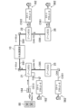
図2は、第1ゾーンECU21の機能構成例を示している。
FIG. 2 shows an example of the functional configuration of the
第1ゾーンECU21は、通信部120と、プロトコル変換部140と、信号変換部150とを備える。プロトコル変換部140は、CAN変換部141と、LIN変換部142とを備える。信号変換部150は、デジタル入力回路151、アナログ入力回路152、コントロール出力回路153,154を備える。
The
第1ゾーンECU21には、基幹ネットワークと接続される通信ポート(以下、基幹ポートという)として、イーサネットケーブルEB1が接続される基幹ポート101と、CAN-FDケーブルCB5が接続される基幹ポート102とが設けられている。換言すると、基幹ポート101及び基幹ポート102は、基幹ネットワーク上を伝送される信号である基幹ネットワーク信号が入出力されるポートである。
The
第1ゾーンECU21には、デバイス側ネットワークと接続される通信ポートとして、通信ポート111~118が設けられている。第1ゾーンECU21は、通信ポート111~113を経由してCAN信号の入出力を行い、通信ポート114を経由してLIN信号の入出力を行い、通信ポート115を経由してデジタル制御信号の入力を行い、通信ポート116を経由してアナログ制御信号の入力を行い、通信ポート117,118を経由してアナログ制御信号の出力を行う。通信ポート111には、例えば、スマートECU161が接続され、その先にエアバック装置D11が接続される。通信ポート112には、例えば、サイドドアを施錠/開錠するためのスマートアクチュエータ162が接続される。通信ポート113には、例えば、ブザー音等を発するためのスマートアクチュエータ163が接続される。通信ポート114には、例えば、キーレス装置を作動させるためのセンサ164(以下、キーレスセンサ164という)が接続される。通信ポート115には、例えば、スイッチ165(例えば、クラッチカットスイッチ、ブレーキスイッチ等)が接続される。通信ポート116には、例えば、センサ166(例えば、アクセルペダルセンサ、クラッチストロークセンサ等)が接続される。通信ポート117には、例えば、ドアミラーのターンランプ167が接続される。通信ポート118には、例えば、アクチュエータ168(例えば、ホーン、キーレスブザー、メーター装置等に付属して設けられた表示灯等)が接続される。なお、図面では、説明がわかりやすいように、スマートアクチュエータ162に加えて、ロック機構のシンボルマークを図示している。また、スマートアクチュエータ163に加えて、音源機構のシンボルマークを図示している。
The
なお、具体的な図示は省略するが、各通信ポート111~118に対し、車載デバイスから延びるケーブルの先端に設けられたコネクタを差し込むことで、車載デバイスの取り付けや取り外しができるように構成されていてもよい。また、各通信ポート111~118にスマートコネクタ(図示省略)が接続され、その先に、車載デバイスが取り付けられるようにしてもよい。スマートコネクタは、例えば、アナログ/デジタル変換回路やドライバ回路等が内蔵され、車載デバイスとしてのアクチュエータに駆動信号を送信する機能を有していたり、車載デバイスとしてのセンサからの入力信号をゾーンECU2に伝達したりする機能を有する。
Although specific illustrations are omitted, the configuration is such that an in-vehicle device can be attached or removed by inserting a connector provided at the end of a cable extending from the in-vehicle device into each of the
通信部120は、基幹ポート101に接続された第1送受信部121と、基幹ポート102に接続された第2送受信部122と、ネットワークマネジメント部123とを備える。
The
第1送受信部121は、基幹ポート101及びイーサネットケーブルEB1を介して中央演算装置10との間で基幹ネットワーク信号(イーサネット信号)を送受信する機能を有する。具体的な図示は省略するが、第1送受信部121は、例えば、イーサネット信号を生成する符号化回路と、符号化回路で生成されたイーサネット信号を中央演算装置10に出力するドライバ回路と、中央演算装置10から出力されたイーサネット信号を受信するレシーバ回路と、レシーバ回路で受信されたイーサネット信号を復号化する復号化回路とを備える。
The first transmitting/receiving
第2送受信部122は、基幹ポート102及びCAN-FDケーブルCB5を介して第5ゾーンECU25との間で基幹ネットワーク信号(CAN-FD信号)を送受信する機能を有する。具体的な図示は省略するが、第2送受信部122は、例えば、CAN-FD信号を生成する符号化回路と、符号化回路で生成されたイーサネット信号を第5ゾーンECU25に出力するドライバ回路と、第5ゾーンECU25から出力されたCAN-FD信号を受信するレシーバ回路と、レシーバ回路で受信されたCAN-FD信号を復号化する復号化回路とを備える。
The second transmitting/receiving
ネットワークマネジメント部123は、(a)基幹ネットワーク上において、すなわち基幹ポート101,102の間で基幹ネットワーク信号を中継する中継機能と、(b)基幹ネットワーク信号の中から自ECUに接続されたデバイス用の信号を抽出して分配する分配機能と、(c)自ECUに接続されたデバイスから中央演算装置10及び/または他のゾーンECU2に伝送するデータを集約する集約機能とを備える。なお、以下の説明(他のゾーンECU2についての説明を含む)では、上記のそれぞれの機能を単に、「(a)中継機能」、「(b)分配機能」、「(c)集約機能」と呼ぶ場合がある。
The
プロトコル変換部140は、通信方式間でデータがやり取りできるようにプロトコル変換をする。具体的には、プロトコル変換部140は、ネットワークマネジメント部123に接続され、上記のネットワークマネジメント部123の「(a)中継機能」、「(b)分配機能」、「(c)集約機能」のそれぞれに応じたプロトコル変換を行う。なお、本実施形態において、プロトコル変換には、CANと、CAN-FDとの間におけるデータ長変換等の変換処理も含むものとする。
The
「(a)中継機能」では、ネットワークマネジメント部123は、中央演算装置10から入力されたイーサネット信号の中で、第5ゾーンECU25に送信するデータ(以下、中継データという)を抽出してプロトコル変換部140に出力する。プロトコル変換部140では、中継データをCANプロトコルデータに変換し、ネットワークマネジメント部123に出力する。ネットワークマネジメント部123では、上記CANプロトコルデータを基にCAN信号を生成する。そして、第2送受信部122が基幹ポート102を介して上記CAN信号を第5ゾーンECU25に出力する。同様に、ネットワークマネジメント部123は、第5ゾーンECU25から入力されたCAN-FD信号の中で、中央演算装置10に送信するデータ(以下、中継データという)を抽出してプロトコル変換部140に出力する。プロトコル変換部140は、中継データをイーサネットプロトコルに準拠した形式のデータに変換し、ネットワークマネジメント部123に出力する。ネットワークマネジメント部123では、上記の変換データを基にイーサネット信号を生成する。そして、第1送受信部121が基幹ポート101を介して上記イーサネット信号を中央演算装置10に出力する。
In the "(a) relay function," the
以上を遅延時間の観点でまとめると、「(a)中継機能」に係る処理(以下、中継処理という)では、少なくとも、受信遅延時間、プロトコル変換時間、送信遅延時間が発生する。受信遅延時間は、通信部120での受信処理による受信遅延時間である。受信遅延時間には、例えば、第1送受信部121または第2送受信部122において物理層等の受信処理時間及びその後の復号化処理時間、並びに、ネットワークマネジメント部123において中継データを抽出する抽出処理時間が含まれる。プロトコル変換時間には、プロトコル変換部140での通信方式間のプロトコル変換の時間が含まれる。送信遅延時間は、プロトコル変換されたデータを通信部120から送信するための送信処理による遅延時間である。送信遅延時間には、例えば、第1送受信部121または第2送受信部122における符号化処理時間及び物理層等による送信処理時間が含まれる。
To summarize the above from the perspective of delay time, in the process related to "(a) relay function" (hereinafter referred to as relay process), at least a reception delay time, a protocol conversion time, and a transmission delay time occur. The reception delay time is a reception delay time due to reception processing in the
また、第1ゾーンECU21では、起動動作や復帰動作に係る起動遅延時間が発生する場合がある。例えば、「(a)中継機能」では、イーサネットケーブルEB1またはCAN-FDケーブルCB5から起動信号が送られてくることが想定される。この起動信号を受けた場合に、通信部120のPLL(Phase Locked Loop)回路が停止しているような状態のときには、起動遅延時間として、例えば、物理層の起動/安定化時間及び隣接する中央演算装置10やゾーンECU2との間の通信確立に要する通信確立時間が生じる。通信部120のPLL回路が停止しているような状態として、例えば、第1ゾーンECU21の電源オフ状態またはスリープ状態がある。
Further, in the
「(b)分配機能」では、ネットワークマネジメント部123は、中央演算装置10から入力されたイーサネット信号の中から、自ECUに接続されたデバイス用のデータ(以下、自ECU用データという)を抽出する。ネットワークマネジメント部123は、上記自ECU用データについて、プロトコル変換部140に接続されたデバイス用のデータか、信号変換部150に接続されたデバイス用のデータかを判断し、それぞれに分配する。プロトコル変換部140では、ネットワークマネジメント部123から通信ポート111~113に接続されたデバイス用のデータが受信されると、CAN変換部141が受信データをCANプロトコルに準拠した信号に変換して通信ポート111~113に出力する。これにより、スマートECU161、スマートアクチュエータ162,163のそれぞれに中央演算装置からの信号(例えば、制御信号)が伝達される。信号変換部150では、ネットワークマネジメント部123から通信ポート117に接続されたターンランプ167の制御用のデータが受信されると、コントロール出力回路153が中央演算装置10から受けた制御値に従って、例えばターンランプ167のアナログ制御信号を生成し、通信ポート117に出力する。同様に、信号変換部150において、ネットワークマネジメント部123から通信ポート118に接続されたアクチュエータ168の制御用のデータが受信されると、コントロール出力回路154が中央演算装置10から受けた制御値に従って、例えばアクチュエータ168のアナログ制御信号を生成し、通信ポート118に出力する。なお、第5ゾーンECU25から入力されたCAN信号の中に自ECUに接続されたデバイス用のデータが含まれていた場合についても上記の中央演算装置10の場合と同様の処理が行われる。
In "(b) distribution function", the
以上を遅延時間の観点でまとめると、「(b)分配機能」に係る処理(以下、分配処理という)では、プロトコル変換部140を経由する場合、少なくとも、受信遅延時間、プロトコル変換時間、処理遅延時間が発生する。また、分配処理において、信号変換部150を経由する場合、少なくとも、通信部120での受信処理による受信遅延時間、信号変換部150での処理遅延時間が発生する。受信遅延時間は、通信部120での受信処理による遅延時間であり、例えば、中継処理の場合と同様に、受信処理時間、復号化処理時間及びネットワークマネジメント部123において自ECU用データを抽出する抽出処理時間が含まれる。プロトコル変換時間には、プロトコル変換部140による通信方式間のプロトコル変換の時間が含まれる。処理遅延時間には、スマートECU161またはスマートアクチュエータ162,163での処理遅延時間が含まれる。
To summarize the above from the perspective of delay time, in the process related to "(b) distribution function" (hereinafter referred to as distribution process), when going through the
また、第1ゾーンECU21の「(b)分配機能」では、第1ゾーンECU21に接続された車載デバイスが電源オフ状態やスリープ状態の場合、上記の「(a)中継機能」で記載した起動遅延時間に加えて、または、代えて車載デバイスの復帰のための起動遅延時間が発生する。
In addition, in the "(b) distribution function" of the
「(c)集約機能」では、例えば、プロトコル変換部140が、キーレスセンサ164からの開錠/施錠信号(LIN信号)を受信し、LINプロトコルに準拠したデータからイーサネットプロトコルに準拠したデータに変換して、ネットワークマネジメント部123に送信する。また、例えば、信号変換部150では、デジタル入力回路151がスイッチ165からの入力信号を受信し、アナログ入力回路152がセンサ166からの入力信号を受信し、それぞれ受信データをネットワークマネジメント部123に送信する。ネットワークマネジメント部123では、プロトコル変換部140からの受信データ及び信号変換部150からの受信データを集約する。第1送受信部121では、ネットワークマネジメント部123で集約されたデータをイーサネット信号として基幹ポート101を介して中央演算装置10に出力する。なお、集約機能で集約されたデータを第5ゾーンECU25に送信する場合についても、上記の中央演算装置10に出力する場合と同様の処理が行われる。
In the "(c) aggregation function", for example, the
また、例えば、プロトコル変換部140が、キーレスセンサ164からの出力信号(LIN信号)を受信した場合に、第1ゾーンECU21の電源オフ状態またはスリープ状態のとき、第1ゾーンECU21では、通信部120での復帰動作が実行される。また、通信部120は、復帰動作完了後に、中央演算装置10及び/または第5ゾーンECU25に、キーレスセンサ164から開錠(施錠)信号を受信したことを送信する。この送信信号は、中央演算装置10及び/または第5ゾーンECU25を復帰動作させるための復帰信号としての機能を有する。
Further, for example, when the
以上を遅延時間の観点でまとめると、「(c)集約機能」に係る処理(以下、集約処理という)において、プロトコル変換部140を経由する場合、少なくとも、プロトコル変換時間、集約処理時間、送信遅延時間が発生する。また、集約処理において、信号変換部150を経由する場合、少なくとも、集約処理時間、送信遅延時間が発生する。プロトコル変換時間には、プロトコル変換部140による通信方式間のプロトコル変換の時間が含まれる。集約処理時間には、ネットワークマネジメント部123において、信号変換部150及び/またはプロトコル変換部140から受信したデータを、それぞれの送信先ごとに集約するための時間が含まれる。送信遅延時間は、ネットワークマネジメント部123で集約されたデータを通信部120から送信するための送信処理による遅延時間である。送信遅延時間には、例えば、第1送受信部121または第2送受信部122における符号化処理時間及び物理層等による送信処理時間が含まれる。
To summarize the above from the perspective of delay time, in the process related to "(c) aggregation function" (hereinafter referred to as aggregation process), when going through the
また、第1ゾーンECU21の「(c)集約機能」では、第1ゾーンECU21に接続された所定の車載デバイスからの復帰信号(例えば、キーレスセンサ164の開錠信号)を受けた場合に、中央演算装置10や第5ゾーンECU25に上記復帰信号を送信するための起動遅延時間が発生する。例えば、通信部120のPLL回路が停止しているような状態の場合、起動遅延時間として、物理層の起動/安定化時間、及び、隣接する中央演算装置10やゾーンECU2との間の通信確立に要する通信確立時間が発生する。また、起動遅延時間には、ネットワークマネジメント部123での復帰処理時間も含まれる場合がある。
In addition, in the "(c) aggregation function" of the
図3は、第3ゾーンECU23の機能構成例を示している。なお、ここでは、第1ゾーンECU21と共通の構成について説明を省略する場合がある。
FIG. 3 shows an example of the functional configuration of the
第3ゾーンECU23は、通信部320と、プロトコル変換部340と、信号変換部350とを備える。プロトコル変換部340は、CAN変換部341を備える。信号変換部350は、デジタル入力回路351と、アナログ入力回路352と、コントロール出力回路353とを備える。
The
第3ゾーンECU23には、イーサネットケーブルEB3が接続される基幹ポート301と、イーサネットケーブルEB5が接続される基幹ポート302とが設けられている。換言すると、基幹ポート301及び基幹ポート302は、基幹ネットワーク信号が入出力されるポートである。
The
第3ゾーンECU23には、デバイス用ポートとして、通信ポート311~315が設けられている。第3ゾーンECU23は、通信ポート311,312を経由してCAN信号の入出力を行い、通信ポート313を経由してデジタル制御信号の入力を行い、通信ポート314を経由してアナログ制御信号の入力を行い、通信ポート315を経由してアナログ制御信号の出力を行う。通信ポート311には、例えば、車両1の衝突を検知する衝突検知部361が接続される。通信ポート312には、例えば、車両フロント側のターンランプを動作させるためのスマートアクチュエータ362が接続される。通信ポート313には、例えば、スイッチ363(例えば、ウォッシャーレベルスイッチ、フードスイッチ等)が接続される。通信ポート314には、例えば、センサ364(例えば、外気温センサ、エアフローセンサ等)が接続される。通信ポート315には、例えば、アクチュエータ365(例えば、ホーン、キーレスブザー等)が接続される。なお、図面では、説明がわかりやすいように、スマートアクチュエータ362に加えて、ターンランプのシンボルマークを図示している。
The
通信部320は、基幹ポート301に接続された第3送受信部321と、基幹ポート302に接続された第4送受信部322と、ネットワークマネジメント部323とを備える。なお、通信部320において、本願発明に関連する構成及び機能は、前述の第1ゾーンECU21の通信部120と同様であり、ここではその詳細説明を省略する。具体的には、第1ゾーンECU21の通信部120と第3ゾーンECU23の通信部320とを比較すると、第1ゾーンECU21では第2送受信部122がCAN-FDプロトコルに準拠し、第3ゾーンECU23では第4送受信部322がイーサネットプロトコルに準拠している点が異なる。しかしながら、各通信方式に準拠した送受信回路の構成や遅延情報は、従来から知られている技術を基に置き換えることができる。
The
プロトコル変換部340は、通信方式間でデータがやり取りできるようにプロトコル変換をする。ここでは、プロトコル変換部340について、前述の第1ゾーンECU21のプロトコル変換部140との相違点を中心に説明するものとし、共通する内容について説明を省略する場合がある。
The
第3ゾーンECU23は、「(a)中継機能」において、イーサネット信号-イーサネット信号間の中継を行う。したがって、プロトコル変換部340では、前述のプロトコル変換部140のように、中継処理の過程でのプロトコル変換を必要としない。すなわち、第3ゾーンECU23の中継処理では、少なくとも、受信遅延時間、送信遅延時間が発生する。また、第3ゾーンECU23では、起動動作や復帰動作に係る起動遅延時間が発生する場合がある。なお、受信遅延時間、送信遅延時間及び起動遅延時間については、前述の第1ゾーンECU21と同様であり、ここではその詳細説明を省略する。
The
第3ゾーンECU23の「(b)分配機能」及び分配処理による遅延時間は、前述の第1ゾーンECU21と共通した内容であり、ここではその詳細説明を省略する。遅延時間の観点でまとめのみ記載すると、第3ゾーンECU23の分配処理において、(1)プロトコル変換部340を経由する場合、少なくとも、受信遅延時間、プロトコル変換時間、処理遅延時間が発生する。また、(2)信号変換部350を経由する場合、少なくとも、通信部320での受信処理による受信遅延時間、信号変換部350での処理遅延時間が発生する。また、前述の起動動作や復帰動作において、第3ゾーンECU23に接続された車載デバイスが電源オフ状態やスリープ状態の場合、車載デバイスの復帰のための起動遅延時間が発生する場合がある。なお、受信遅延時間、プロトコル変換時間、処理遅延時間及び起動遅延時間については、前述の第1ゾーンECU21と同様であり、ここではその詳細説明を省略する。
The "(b) distribution function" of the
第3ゾーンECU23の「(c)集約機能」及び集約処理による遅延時間は、前述の第1ゾーンECU21と共通した内容であり、ここではその詳細説明を省略する。遅延時間の観点でまとめのみ記載すると、第3ゾーンECU23の集約処理において、(1)プロトコル変換部340を経由する場合、少なくとも、プロトコル変換時間、集約処理時間、送信遅延時間が発生する。また、(2)信号変換部350を経由する場合、少なくとも、集約処理時間、送信遅延時間が発生する。また、第3ゾーンECU23に接続された所定の車載デバイスからの復帰信号を受けた場合に、中央演算装置10や第4ゾーンECU24に上記復帰信号を送信するための起動遅延時間が発生する場合がある。なお、プロトコル変換時間、集約処理時間、送信遅延時間及び起動遅延時間については、前述の第1ゾーンECU21と同様であり、ここではその詳細説明を省略する。
The "(c) aggregation function" of the
図4は、第5ゾーンECU25の機能構成例を示している。なお、ここでは、第1ゾーンECU21及び/または第3ゾーンECU23と共通の構成について説明を省略する場合がある。
FIG. 4 shows an example of the functional configuration of the
第5ゾーンECU25は、通信部520と、プロトコル変換部540と、信号変換部550とを備える。プロトコル変換部540は、CAN変換部541と、LIN変換部542とを備える。信号変換部550は、デジタル入力回路551と、アナログ入力回路552と、コントロール出力回路553とを備える。
The
第5ゾーンECU25には、CAN-FDケーブルCB5が接続される基幹ポート501と、CAN-FDケーブルCB8が接続される基幹ポート502とが設けられている。換言すると、第5ゾーンECU25では、基幹ポート501及び基幹ポート502に入出力されるのがCAN-FD信号であり、基幹ポート501と基幹ポート502とが直接接続されている。
The
第5ゾーンECU25には、デバイス用ポートとして、通信ポート511~516が設けられている。第5ゾーンECU25は、通信ポート511,512を経由してCAN信号の入出力を行い、通信ポート513を経由してLIN信号の入出力を行い、通信ポート514を経由してデジタル制御信号の入力を行い、通信ポート515を経由してアナログ制御信号の入力を行い、通信ポート516を経由してアナログ制御信号の出力を行う。通信ポート511には、例えば、ブザー音等を発するためのスマートアクチュエータ561が接続される。通信ポート512には、例えば、サイドドアをロックするためのスマートアクチュエータ562が接続される。通信ポート513には、例えば、バックソナー装置563が接続される。通信ポート514には、例えば、スイッチ564が接続される。例えば、通信ポート515には、センサ565(例えば、フューエルセンサ、キックセンサ等)が接続される。通信ポート516には、例えば、車両左後方に設けられたターンライト566が接続される。なお、図面では、説明がわかりやすいように、スマートアクチュエータ561に加えて、音源機構のシンボルマークを図示している。また、スマートアクチュエータ562に加えて、ロック機構のシンボルマークを図示している。
The
通信部520は、基幹ポート501と基幹ポート502とを接続する共通通信線に接続された送受信部521と、ネットワークマネジメント部522とを備える。具体的な図示は省略するが、送受信部521は、例えば、CAN-FD信号を生成する符号化回路と、上記共通通信線に接続されたドライバ回路及びレシーバ回路と、レシーバ回路で受信されたCAN-FD信号を復号化する復号化回路とを備える。
The
プロトコル変換部540は、通信方式間でデータがやり取りできるようにプロトコル変換をする。ここでは、プロトコル変換部540について、前述の第1ゾーンECU21のプロトコル変換部140との相違点を中心に説明するものとし、共通する内容について説明を省略する場合がある。
The
第5ゾーンECU25では、基幹ポート501と基幹ポート502とが直接接続されているので、「(a)中継機能」という概念がない。すなわち、第5ゾーンECU25では、隣接する2つのゾーンECU2間を中継する中継処理は行われず、基幹ポート501と基幹ポート502との間の遅延時間は、共通通信線の信号伝搬時間のみであり、極めて小さい。同様に、第5ゾーンECU25の「(a)中継機能」において、起動遅延時間は発生しない。
In the
第5ゾーンECU25の「(b)分配機能」及び分配処理による遅延時間は、前述の第1ゾーンECU21と共通した内容であり、ここではその詳細説明を省略する。遅延時間の観点でまとめのみ記載すると、第5ゾーンECU25の分配処理において、(1)プロトコル変換部540を経由する場合、少なくとも、受信遅延時間、プロトコル変換時間、処理遅延時間が発生する。また、(2)信号変換部550を経由する場合、少なくとも、通信部520での受信処理による受信遅延時間、信号変換部550での処理遅延時間が発生する。また、前述の起動動作や復帰動作において、第5ゾーンECU25に接続された車載デバイスが電源オフ状態やスリープ状態の場合、車載デバイスの復帰のための起動遅延時間が発生する場合がある。なお、受信遅延時間、プロトコル変換時間、処理遅延時間及び起動遅延時間については、前述の第1ゾーンECU21と同様であり、ここではその詳細説明を省略する。
The "(b) distribution function" of the
第5ゾーンECU25の「(c)集約機能」及び集約処理による遅延時間は、前述の第1ゾーンECU21と共通した内容であり、ここではその詳細説明を省略する。遅延時間の観点でまとめのみ記載すると、第5ゾーンECU25の集約処理において、(1)プロトコル変換部540を経由する場合、少なくとも、プロトコル変換時間、集約処理時間、送信遅延時間が発生する。また、(2)信号変換部550を経由する場合、少なくとも、集約処理時間、送信遅延時間が発生する。また、第5ゾーンECU25に接続された所定の車載デバイスからの復帰信号を受けた場合に、第1ゾーンECU21や第6ゾーンECU26に上記復帰信号を送信するための起動遅延時間が発生する場合がある。なお、プロトコル変換時間、集約処理時間、送信遅延時間及び起動遅延時間については、前述の第1ゾーンECU21と同様であり、ここではその詳細説明を省略する。
The "(c) aggregation function" of the
<車両制御システムの設計方法>
-概要-
前述の「発明が解決しようとする課題」に記載したとおり、将来的に、演算処理機能及び各アクチュエータの制御機能が、車両全体の動作を統括して管理するような中央演算装置に集約されていくことが想定される。このことは、現在、車両のゾーン毎に設けられたECUや、引用文献1のように機能毎に設けられたECU(以下、まとめて「従来型のECU」と称する)に搭載されている演算機能や制御機能が、中央演算装置に取り込まれていくことを意味する。
<Vehicle control system design method>
-overview-
As stated in the above-mentioned "Problem to be Solved by the Invention," in the future, the calculation processing function and the control function of each actuator will be integrated into a central processing unit that will centrally manage the operation of the entire vehicle. It is expected that this will happen. This is because the calculations currently installed in ECUs installed in each zone of a vehicle or ECUs installed in each function as in Cited Document 1 (hereinafter collectively referred to as "conventional ECUs") This means that functions and control functions are incorporated into a central processing unit.
そこで、本願発明者らは、鋭意検討を重ね、従来型のECUに搭載された演算機能や制御機能を中央演算装置に取り込んでいくのに際して、より多くの機能を取り込むこと、及び、そのための設計工数をできるだけ削減することを実現する設計方法を見いだした。 Therefore, the inventors of the present application have conducted extensive studies, and when incorporating the calculation functions and control functions installed in conventional ECUs into the central processing unit, they have decided to incorporate more functions and to develop a design for this purpose. We have discovered a design method that reduces man-hours as much as possible.
簡単に本開示の設計方法の概要を説明すると、従来型のECUを用いた制御方法によって問題なく動作している制御機能を、中央演算装置に取り込む場合に、従来型のECUと大きく異なる要素の1つとして、通信遅延の問題がある。前述のとおり、機能が集約された中央演算装置に対して、各センサや各アクチュエータをそれぞれ直接接続するのは、信号配線が膨大になるため現実的ではないので、車載ネットワークが構築されることが想定される。そうすると、中央演算装置と車載デバイスや車載デバイスを制御するECUとの間に、ネットワークハブ装置やゲートウェイ装置等の中継装置が介在することになり、通信遅延が発生する。そうすると、ある入力や状況が発生してから実際に車載デバイスが動作するまでの応答速度が要求される制御に関して、この通信遅延が問題となる場合がある。 To briefly explain the outline of the design method of the present disclosure, when incorporating control functions that are operating without problems using a control method using a conventional ECU into a central processing unit, it is necessary to incorporate elements that are significantly different from those of a conventional ECU. One problem is communication delay. As mentioned above, it is impractical to directly connect each sensor and each actuator to a central processing unit with integrated functions because it requires a huge amount of signal wiring, so it is difficult to construct an in-vehicle network. is assumed. In this case, a relay device such as a network hub device or a gateway device is interposed between the central processing unit and the in-vehicle device or the ECU that controls the in-vehicle device, resulting in a communication delay. In this case, this communication delay may become a problem with regard to control that requires response speed from the occurrence of a certain input or situation to the actual operation of the in-vehicle device.
特に、中央演算装置に機能を集約する場合、高速かつ大容量のデータ伝送を実現する必要があり、そのためには、高速インターフェース技術を適用する必要がある。一般的に、高速インターフェース技術では、高速信号をやり取りするための物理層を設ける必要があり、その物理層を起動させるために、数十msオーダーの起動時間が必要とされる。また、車載ネットワークにおいて、例えば、CAN、CAN-FD、イーサネットのように、複数の通信プロトコルが混在し、かつ、互いに異なる通信プロトコルに対応する車載デバイス(ゾーンECUを含む)をデイジーチェーン状に接続することが想定される。 In particular, when functions are concentrated in a central processing unit, it is necessary to realize high-speed and large-capacity data transmission, and for this purpose, it is necessary to apply high-speed interface technology. Generally, high-speed interface technology requires a physical layer for exchanging high-speed signals, and activation time on the order of tens of milliseconds is required to activate the physical layer. In addition, in an in-vehicle network, multiple communication protocols coexist, such as CAN, CAN-FD, and Ethernet, and in-vehicle devices (including zone ECUs) that support different communication protocols are connected in a daisy chain. It is assumed that
そこで、本願発明では、特に、起動時間及び/または復帰時間(以下、単に起動時間という)に着目し、この起動時間として許容される起動遅延時間の基準として「許容遅延時間」を設定し、その許容遅延時間を基に、車載デバイスの接続場所を設定する点に特徴がある。または、上記の「許容遅延時間」を設定し、その許容遅延時間を基に、デイジーチェーン状のネットワーク経路を構成する点に特徴がある。起動遅延時間は、信号等の制御の基となる入力が行われる車載デバイス(ゾーンECUを含む)から中央演算装置10までの間の起動遅延時間(以下、入力側起動遅延時間という)と、中央演算装置10から上記入力に対して動作させる車載デバイス側の制御回路(ゾーンECUを含む)までの間の起動遅延時間(以下、出力側通信遅延時間という)とを含む。
Therefore, in the present invention, we particularly focus on the startup time and/or recovery time (hereinafter simply referred to as startup time), and set an "acceptable delay time" as a standard for startup delay time that is allowable as this startup time. The feature is that the connection location of the in-vehicle device is set based on the allowable delay time. Another feature is that the above-mentioned "allowable delay time" is set, and a daisy chain network path is configured based on the allowable delay time. The startup delay time is defined as the startup delay time from the in-vehicle device (including the zone ECU) to the central processing unit 10 (hereinafter referred to as the input-side startup delay time), where the input that is the basis of control such as signals is made, and the It includes a start-up delay time (hereinafter referred to as output-side communication delay time) from the
すなわち、本願発明では、入力側起動遅延時間及び出力側起動遅延時間と、許容遅延時間との関係に基づいて、車載デバイスの接続場所を設定する、及び/または、デイジーチェーン状のネットワーク経路を構成する点に特徴がある。ここで、「許容遅延時間」は、任意に設定することができる時間であり、特に限定されるものではない。例えば、車両安全基準等の標準規格等に基づいて設定されてもよいし、車両の挙動や他の機能との関連性等に基づいて設定されてもよい。また、運転者等に違和感やストレスを与えないという観点で設定されてもよい。 That is, in the present invention, the connection location of the in-vehicle device is set based on the relationship between the input side startup delay time, the output side startup delay time, and the allowable delay time, and/or a daisy chain network path is configured. It is characterized by the fact that Here, the "allowable delay time" is a time that can be set arbitrarily, and is not particularly limited. For example, it may be set based on standards such as vehicle safety standards, or it may be set based on the behavior of the vehicle or its relationship with other functions. Further, it may be set from the viewpoint of not giving a sense of discomfort or stress to the driver or the like.
ここで、本実施形態では、図1に示すように、車両1を複数(本実施形態では7つ)のゾーンに分け、各ゾーンにゾーンECU2を設けて、それらを接続することで基幹ネットワークを構築している。そして、各ゾーンECU2に通信ポートを設け、その通信ポートに車載デバイスを接続している。このような構成にすることで、中央演算装置10と各通信ポートとの間の起動遅延時間をあらかじめ把握しやすくなる。すなわち、車載デバイスをゾーンECU2の各通信ポートに接続する前の段階で、通信ポート毎に中央演算装置10との間の通信遅延時間を見積もることができるようになっている。これにより、複雑な演算処理をすることなく、比較的容易に、車載デバイスの接続場所を設定する、及び/または、デイジーチェーン状のネットワーク経路を構成することができる。
Here, in this embodiment, as shown in FIG. 1, the
-車両制御システムの設計フロー-
以下において、図5~図10を用いて、本実施形態の車両制御システムの設計方法について、具体的な設計フローを説明する。なお、例えば、本設計方法を実現するための設計プログラムを用意し、コンピュータを用いてその設計プログラムを実行するように構成されていてもよい。
-Vehicle control system design flow-
Below, a specific design flow of the vehicle control system design method of this embodiment will be explained using FIGS. 5 to 10. Note that, for example, a design program for implementing the present design method may be prepared and the design program may be executed using a computer.
図5において、ステップS1では、車載ネットワークのベースとなるネットワークを構築する。例えば、まず、図6の太線及び中太線で示す基幹ネットワークを構築する。その後、基幹ネットワークでネットワークハブ装置としての機能を有する各ゾーンECU2からのサブネットワークを構成し、中央演算装置10からデイジーチェーン状に広がる車載ネットワークを構成する。なお、実施形態では、説明が煩雑になるのを避けるため、サブネットワークの記載を省略している。
In FIG. 5, in step S1, a network that becomes the base of the in-vehicle network is constructed. For example, first, a backbone network shown by thick lines and medium thick lines in FIG. 6 is constructed. Thereafter, a sub-network from each zone ECU 2 having a function as a network hub device is configured in the backbone network, and an in-vehicle network extending in a daisy chain from the
ステップS2では、制御対象となる車載デバイス(以下、動作デバイスという)の接続先を設定する。動作デバイスの接続先の基準は、特に限定されるものではない。例えば、動作デバイスは、最初の接続先として、配置場所に最も近い位置に設置されているゾーンECU2またはそのゾーンECU2のサブネットワークに接続されたECU(スマートECUを含む)に優先的に接続される。 In step S2, a connection destination of an in-vehicle device to be controlled (hereinafter referred to as an operating device) is set. The criteria for connecting the operating device is not particularly limited. For example, as the first connection destination, the operating device is preferentially connected to the zone ECU 2 installed closest to the installation location or to the ECU (including smart ECU) connected to the subnetwork of the zone ECU 2. .
ステップS3では、情報取得手段(例えば、前述のセンサやスイッチ等)の接続先を設定する。情報取得手段の接続先の基準は、特に限定されるものではない。例えば、情報取得手段は、最初の接続先として、配置場所に最も近い位置に設置されているゾーンECU2またはそのゾーンECU2のサブネットワークに接続されたECU(スマートECUを含む)に優先的に接続される。 In step S3, the connection destination of the information acquisition means (for example, the above-mentioned sensor or switch) is set. The criteria for the connection destination of the information acquisition means is not particularly limited. For example, as the first connection destination, the information acquisition means is preferentially connected to the zone ECU 2 installed closest to the installation location or the ECU (including smart ECU) connected to the subnetwork of the zone ECU 2. Ru.
ステップS4では、まず、各通信経路の起動時間を算出する。具体的に、センサやスイッチ等の情報取得手段と、動作デバイスとの間の通信経路を特定する。 In step S4, first, the activation time of each communication path is calculated. Specifically, a communication path between an information acquisition means such as a sensor or a switch and an operating device is specified.
図7は、図6の構成からキーレスセンサ164及びドアを施錠/開錠するためのスマートアクチュエータ162,562に関連するネットワークを抽出したものである。図7では、「情報取得手段」が車両用のリモコン80からの情報を取得するキーレスセンサ164であり、「動作デバイス」がドアを施錠/開錠するためのスマートアクチュエータ162,562である場合を示している。
FIG. 7 shows a network associated with the
図7の例の場合、入力側の通信経路として、キーレスセンサ164からLIN信号線を介して第1ゾーンECU21を通り、イーサネットケーブルEB1を介して中央演算装置10に至る経路が特定される。また、図7の例の場合、ドアを施錠/開錠するためのスマートアクチュエータ162,562は、4つ搭載されているので、4つの出力側の通信経路が特定される。
In the case of the example shown in FIG. 7, as the communication path on the input side, a path from the
具体的に、第1の出力側の通信経路として、中央演算装置10からイーサネットケーブルEB1を介して第1ゾーンECU21を通り、CAN信号線CS15を介してスマートアクチュエータ162に至る経路が特定される。第2の出力側の通信経路として、中央演算装置10からイーサネットケーブルEB1を介して第1ゾーンECU21を通り、イーサネットケーブルEB51を介して第7ゾーンECU27を通り、CAN-FDケーブルCB52を介して第5ゾーンECU25を通り、CAN信号線CS51を介してスマートアクチュエータ562に至る経路が特定される。第3の出力側の通信経路として、中央演算装置10からイーサネットケーブルEB2を介して第2ゾーンECU22を通り、CAN信号線CS22を介してスマートアクチュエータ162に至る経路が特定される。第4の出力側の通信経路として、中央演算装置10からイーサネットケーブルEB2を介して第2ゾーンECU22を通り、CAN-FDケーブルCB6を介して第6ゾーンECU26を通り、CAN信号線CS61を介してスマートアクチュエータ562に至る経路が特定される。
Specifically, as the communication path on the first output side, a path from the
次に、各通信経路における起動遅延時間を算出する。例えば、入力側の通信経路において、第1ゾーンECU21から中央演算装置10に向かうネットワークが起動されて中央演算装置10が起動するまでの起動遅延時間(第1起動時間に相当)を算出する。起動遅延時間の算出は、各種のパラメータを設定したシミュレーションのように具体的な演算処理をしてもよいし、あらかじめデータベース(図5ではDBと記載)に登録されているデータを使用して簡単な演算処理をするようにしてもよい。起動遅延時間の算出は、入力側の通信経路及び出力側の通信経路の演算が終了するまで繰り返される。
Next, the activation delay time for each communication path is calculated. For example, in the communication path on the input side, the activation delay time (corresponding to the first activation time) from when the network from the
具体的には、第1の出力側の通信経路において、中央演算装置10から第1ゾーンECU21に向かうネットワークが起動されて第1ゾーンECU21が起動するまでの起動遅延時間(第2起動時間に相当)を算出する。同様に、第2の出力側の通信経路において、中央演算装置10から第5ゾーンECU25に向かうネットワークを構成する第1ゾーンECU21、第7ゾーンECU27が順次起動されて第5ゾーンECU25が起動するまでの起動遅延時間(第2起動時間に相当)を算出する。第3、第4の出力側の通信経路についても同様にして、起動遅延時間を算出する。なお、図5において、各通信経路における起動遅延時間の算出は、並列または同時に実行してもよい。
Specifically, in the communication path on the first output side, there is a startup delay time (equivalent to the second startup time) from when the network from the
図8及び図9は、起動遅延時間について説明するための図であり、一例として、キーレスセンサ164にリモコンからの施錠/開錠のための操作情報が入力されてから、第2ゾーンECU22に接続されたスマートアクチュエータ162によりドアが施錠/開錠されるまでのフローを示している。
8 and 9 are diagrams for explaining the startup delay time. As an example, after inputting operation information for locking/unlocking from the remote control to the
図8及び図9に示すように、例えば、キーレスセンサ164に開錠操作信号が入力されると、キーレスセンサ164において起動/送信信号処理が実行され、第1ゾーンECU21に開錠操作信号が出力される。開錠操作信号は、起動信号の一例である。
As shown in FIGS. 8 and 9, for example, when an unlock operation signal is input to the
キーレスセンサ164では、起動遅延時間t1として、例えば、開錠操作信号を送信するための送信回路の起動時間、送信信号処理による送信遅延時間が発生する。t12は、キーレスセンサ164と第1ゾーンECU21との間の通信経路(LIN信号線CS13)における通信遅延時間(起動遅延時間に相当)である。
In the
第1ゾーンECU21では、前述の「中継処理」が実施されるので、起動遅延時間t13として、通信部120の起動時間、受信処理による受信遅延時間、中央演算装置10への送信処理による送信遅延時間が生じる。t14は、第1ゾーンECU21と中央演算装置10との間の通信経路(イーサネットケーブルEB1)における通信遅延時間(起動遅延時間に相当)である。
In the
中央演算装置10では、起動遅延時間t15として、中央演算装置10の起動時間、第1ゾーンECU21からのイーサネット信号受信に係る受信処理時間、第1ゾーンECU21及び第2ゾーンECU22へのイーサネット信号送信に係る受信処理時間が生じる。中央演算装置10の起動時間には、例えば、PLL等の物理層(図示省略)の起動時間が含まれる。送信遅延時間には、例えば、符号化処理時間及び物理層等による送信処理時間が含まれる。受信遅延時間には、例えば、物理層等の受信処理時間及びその後の復号化処理時間が含まれる。なお、中央演算装置10では、故障判定処理、制御動作決定処理(フェイルセーフ処理を含む)が実行される。これらの故障判定処理及び制御動作決定処理は、通信遅延時間には含まれないが、例えば、中央演算装置10にこれらの処理を取り込むことで、従来型のECUよりも各処理に時間がかかる場合、その処理時間を起動遅延時間に含めるようにしてもよい。t16は、中央演算装置10と第2ゾーンECU22との間の通信経路(イーサネットケーブルEB2)における通信遅延時間(起動遅延時間に相当)である。
In the
第2ゾーンECU22では、前述の「中継処理」が実施されるので、起動遅延時間t17として、通信部(第1ゾーンECU21の通信部120に相当)の起動時間、受信処理による受信遅延時間、プロトコル変換部(第1ゾーンECU21のプロトコル変換部140に相当)によるプロトコル変換時間、中央演算装置10への送信処理による送信遅延時間が生じる。t18は、第2ゾーンECU22とスマートアクチュエータ162との間の通信経路(CAN信号線CS22)における通信遅延時間(起動遅延時間に相当)である。
In the
スマートアクチュエータ162に第2ゾーンECU22からの開錠操作信号が受信されると、ドア開錠される。第2ゾーンECU22で開錠操作信号を出力してから、スマートアクチュエータ162がドアを開錠するまでの間の処理において、何らかの起動遅延時間t19が発生する場合に、その起動遅延時間t19を、起動遅延時間t11~t18の計算結果に加算するようにしてもよい。
When the
以上のようにして、図5のステップS4では、キーレスセンサ164に開錠操作信号が入力された時刻Tsからスマートアクチュエータ162から制御信号が出力される時刻Tfまでの間の起動遅延時間T10が算出される。例えば、キーレスセンサ164にリモコンからの施錠/開錠のための操作情報が入力されてから、第2ゾーンECU22に接続されたスマートアクチュエータ162によりドアが施錠/開錠されるまでの起動遅延時間T10は、起動遅延時間t11~t19の和である。
As described above, in step S4 of FIG. 5, the activation delay time T10 from the time Ts when the unlock operation signal is input to the
図5のステップS4では、すべての動作対象のデバイスについて、上記の起動遅延時間の算出が行われる。例えば、図7の例では、4つのスマートアクチュエータ162,562のそれぞれについて、スマートアクチュエータ162に操作信号が入力された場合の起動遅延時間が算出される。
In step S4 of FIG. 5, the above-mentioned startup delay time is calculated for all operation target devices. For example, in the example of FIG. 7, the activation delay time when an operation signal is input to the
次のステップS5では、上記の起動遅延時間T10と、ドアロック装置についての許容遅延時間とが比較される。許容遅延時間とは、例えば、作動対象の車載デバイスについて、起動信号が情報取得手段に入力されてから車載デバイスが接続されたゾーンECUまたは出力回路が制御信号を出力させるまでに許容される時間であり、例えば、車載デバイス毎にあらかじめ設定されている。例えば、ドアロック装置の場合、キーレスセンサ164にリモコン80からの操作信号が入力されてから、スマートアクチュエータ162,562に制御信号が出力されるまでに許容される時間が、上記の許容遅延時間に相当する。起動遅延時間T10は、換言すると、複数のゾーンECU2のいずれかに情報取得手段を接続し、複数のゾーンECU2のいずれかに動作対象となる車載デバイス(以下、動作デバイスともいう)を接続した場合に、最低限必要となる起動遅延時間である。そこで、ステップS5では、この起動遅延時間T10を所定の基準時間として設定し、この起動遅延時間T10と、動作デバイスについての許容遅延時間とを比較する。
In the next step S5, the above activation delay time T10 is compared with the allowable delay time for the door lock device. The allowable delay time is, for example, the time allowed for an in-vehicle device to be activated from when a start signal is input to the information acquisition means until the zone ECU or output circuit to which the in-vehicle device is connected outputs a control signal. For example, it is set in advance for each in-vehicle device. For example, in the case of a door lock device, the time allowed from when an operation signal from the
そして、例えば、すべてのスマートアクチュエータ162,562についての起動遅延時間が許容遅延時間以内であれば(ステップS5でYES)、スマートアクチュエータ162,562についての設計処理は終了する。
For example, if the activation delay time for all
一方で、スマートアクチュエータ162,562についての起動遅延時間が許容遅延時間を超える場合(ステップS5でNO)、フローはステップS6に進む。
On the other hand, if the activation delay time for the
ステップS6では、設計変更場所を検討する。例えば、情報取得手段及び/または動作デバイスの接続先の変更を検討する。換言すると、第1起動時間と第2起動時間との合計時間が所定の遅延時間未満になるように、複数のゾーンECU2の中から情報取得手段の接続先及び/または車載デバイスの接続先を決定するという作業を行う。上記の例では、第1起動時間は、情報取得手段としてのキーレスセンサ164にリモコン80からの操作信号が入力されてから、中央演算装置10が起動するまでの時間である。また、第2起動時間は、中央演算装置から動作デバイスとしてのドアロック装置が接続されたゾーンECU2またはドアロック装置の制御回路が起動するまでの時間である。ここで、例えば、図7のネットワーク構成において、第5ゾーンECU25に接続されたスマートアクチュエータ562の起動遅延時間がNGの場合に、第5ゾーンECU25に接続されたスマートアクチュエータ562を、第1ゾーンECU21に接続することを試してもよい。接続を変更した場合、例えば、図5のステップS4,S5の処理を再度実行するとよい。
In step S6, a design change location is considered. For example, consider changing the connection destination of the information acquisition means and/or operating device. In other words, the connection destination of the information acquisition means and/or the connection destination of the in-vehicle device is determined from among the plurality of zone ECUs 2 so that the total time of the first startup time and the second startup time is less than the predetermined delay time. Do the work of doing. In the above example, the first activation time is the time from when the operation signal from the
また、例えば、図7のネットワーク構成において、第5ゾーンECU25に接続されたスマートアクチュエータ562の起動遅延時間がNGの場合に、ネットワーク構成を変更するようにしてもよい。例えば、図10(図1のネットワーク構成に相当)では、図7からネットワーク構成を変更した例を示している。具体的に、図10の例では、第1ゾーンECU21と第5ゾーンECU25との間の接続に関し、第7ゾーンECU27を経由する構成に代えて、第1ゾーンECU21と第5ゾーンECU25との間をCAN-FDケーブルCB5で直接接続するようにしている。このように、中央演算装置10とゾーンECU2との間に介在するゾーンECUの数を減らしたり、相互間を接続する通信プロトコルを変更することで、起動遅延時間を短縮させることも可能である。なお、図7から図10の変更をする場合、基幹ネットワークの構成を変更している。一方で、基幹ネットワークは、基盤となるネットワークであり、一般的には、基幹ネットワークの下にも多数のネットワーク(デイジーチェーン状のネットワークを含む)が構成されるので、まずは、基幹ネットワークは変更せずに、ゾーンECU以降のネットワークを変更するとよい。
Further, for example, in the network configuration of FIG. 7, if the activation delay time of the
以上のように、本実施形態によると、複数のゾーンECU2のうちの情報取得手段から起動信号を受信する所定のゾーンECU(以下、第1ゾーンECUと称する)から中央演算装置10に向かうネットワークが順次起動されて中央演算装置10が起動するまでの第1起動時間を算出する。また、中央演算装置からの起動信号にしたがって動作する車載デバイスに制御信号を出力する所定のゾーンECU(以下、第2ゾーンECUと称する)に向かうネットワークが順次起動されて第2ゾーンECUが起動するまでの第2起動時間を算出する。そして、第1起動時間と第2起動時間との合計時間が所定の許容遅延時間未満になるように、情報取得手段の接続先、前記車載デバイスの接続先、及び/またはネットワーク経路を決定するようにしている。ここでのネットワーク経路とは、第1ゾーンECUから中央演算装置10に向かうネットワーク経路及び中央演算装置10から第2ゾーンECUに向かうネットワーク経路を含む。
As described above, according to the present embodiment, a network from a predetermined zone ECU (hereinafter referred to as a first zone ECU) that receives an activation signal from the information acquisition means among the plurality of zone ECUs 2 to the
これにより、車載ネットワークにおいて、複数の通信プロトコルが混在し、かつ、互いに異なる通信プロトコルがデイジーチェーンで接続されるような複雑なネットワークシステムにおいて、起動遅れを考慮したネットワークを構成することができる。また、上記の実施形態のように、許容遅延時間を設けることで、複雑な演算処理等をする前に、大枠で車載ネットワークの構成及び車載デバイス(情報取得手段、動作デバイスを含む)の接続先を決定することができる。なお、本開示において、ゾーンECUとは、上記実施形態で説明したゾーンECU2に加えて、ゾーンECU2に接続されたスマートECUを包含する概念である。 As a result, in a complex network system in which a plurality of communication protocols coexist and different communication protocols are connected in a daisy chain in an in-vehicle network, it is possible to configure a network that takes startup delay into consideration. In addition, as in the above embodiment, by setting an allowable delay time, it is possible to determine the general configuration of the in-vehicle network and the connection destinations of in-vehicle devices (including information acquisition means and operating devices) before performing complex arithmetic processing. can be determined. Note that in the present disclosure, the zone ECU is a concept that includes smart ECUs connected to the zone ECU 2 in addition to the zone ECU 2 described in the above embodiment.
また、上記実施形態では、車両1を複数(本実施形態では7つ)のゾーンに分け、各ゾーンにゾーンECU2を設けて、それらを接続することで基幹ネットワークを構築している。そして、各ゾーンECU2に通信ポートを設け、その通信ポートに対して、コネクタ等を用いて車載デバイスを接続するようにしている。これにより、各ゾーンECU2と中央演算装置10との間の起動遅延時間をあらかじめシミュレーション等で求めることができるようになる。そうすると、情報取得手段の接続先及び動作デバイスの接続先を決定するのに際して、あらかじめ接続先として不適格なゾーンECUを判別することができ、設計効率を高めることができる。
Further, in the embodiment described above, the
(実施形態2)
次に、図11~図14を用いて、実施形態2の設計方法について説明する。なお、車載ネットワークシステムの構成は、上記実施形態1と共通であり、ここではその詳細説明を省略する。
(Embodiment 2)
Next, the design method of the second embodiment will be explained using FIGS. 11 to 14. Note that the configuration of the in-vehicle network system is the same as in the first embodiment, and detailed explanation thereof will be omitted here.
なお、例えば、本設計方法を実現するための設計プログラムを用意し、コンピュータを用いてその設計プログラムを実行するように構成されていてもよい。 Note that, for example, a design program for implementing the present design method may be prepared and the design program may be executed using a computer.
図11において、ステップS10では、センサやスイッチ等の入力側の車載デバイス(以下、入力デバイスという)と、制御対象となる車載デバイス(以下、動作デバイスという)との間の通信経路が特定される。例えば、図12では、入力デバイスが衝突検知部361であり、動作デバイスがエアバック装置D11である場合を示している。図12の例の場合、ステップS10では、入力側の通信経路として、衝突検知部361からLIN信号線CS31を介して第3ゾーンECU23を通り、イーサネットケーブルEB3を介して中央演算装置10に至る経路が特定される。また、出力側の通信経路として、中央演算装置10からイーサネットケーブルEB1を介して第1ゾーンECU21を通り、CAN信号線CS11を介してスマートECU161に至る経路が特定される。
In FIG. 11, in step S10, a communication path between an input-side in-vehicle device such as a sensor or switch (hereinafter referred to as an input device) and an in-vehicle device to be controlled (hereinafter referred to as an operating device) is specified. . For example, FIG. 12 shows a case where the input device is the
ステップS11では、特定された通信経路において、通信プロトコルの変換の有無が判定される。図12の例では、入力側の通信経路では通信プロトコルの変換はないが、出力側の通信経路でイーサネットプロトコルからCANプロトコルへの変換が行われるので、YES判定となり、フローは次のステップS15に進む。 In step S11, it is determined whether or not the communication protocol is to be converted in the specified communication route. In the example of FIG. 12, there is no communication protocol conversion on the input side communication path, but conversion from Ethernet protocol to CAN protocol is performed on the output side communication path, so the determination is YES and the flow moves to the next step S15. move on.
ステップS15~S17では、通信遅延時間が推定される。なお、図11では、便宜上、ステップS15~S17の通信遅延時間及び後述するステップS18の制御処理時間を分けて記載しているが、ステップS15~S18を並列または同時に実行してもよい。 In steps S15 to S17, communication delay time is estimated. Note that in FIG. 11, for convenience, the communication delay time of steps S15 to S17 and the control processing time of step S18, which will be described later, are shown separately, but steps S15 to S18 may be executed in parallel or simultaneously.
図13及び図14は、通信遅延時間について説明するための図であり、衝突検知部361で衝突が検知されてから、エアバック装置D11に信号が出力されるまでの時間的なフローを示している。エアバック装置D11は、作動対象のアクチュエータの一例である。
FIGS. 13 and 14 are diagrams for explaining communication delay time, and show the temporal flow from when a collision is detected by the
図13及び図14に示すように、衝突検知部361に衝突情報が入力されると、衝突検知部361において送信信号処理が実行され、第3ゾーンECU23に衝突検知信号が出力される。衝突検知部361は、情報取得手段の一例であり、衝突検知部361から出力される衝突検知信号は、作動情報の一例である。
As shown in FIGS. 13 and 14, when collision information is input to the
衝突検知部361では、通信遅延時間t1として、送信信号処理による送信遅延時間が発生する。送信遅延時間には、例えば、符号化処理時間及び物理層等による送信処理時間が含まれる。t12は、衝突検知部361と第3ゾーンECU23との間の通信経路(LIN信号線CS31)における通信遅延時間である。
In the
第3ゾーンECU23では、前述の「中継処理」が実施されるので、通信遅延時間t13として、受信処理による受信遅延時間、中央演算装置10への送信処理による送信遅延時間が生じる。t14は、第3ゾーンECU23と中央演算装置10との間の通信経路(イーサネットケーブルEB3)における通信遅延時間である。
In the
中央演算装置10では、通信遅延時間t15として、第3ゾーンECU23からのイーサネット信号受信に係る受信処理時間、第1ゾーンECU21及び第2ゾーンECU22へのイーサネット信号送信に係る受信処理時間が生じる。送信遅延時間には、例えば、符号化処理時間及び物理層等による送信処理時間が含まれる。受信遅延時間には、例えば、物理層等の受信処理時間及びその後の復号化処理時間が含まれる。なお、中央演算装置10では、故障判定処理、制御動作決定処理(フェイルセーフ処理を含む)が実行される。これらの故障判定処理及び制御動作決定処理は、通信遅延時間には含まれないが、例えば、中央演算装置10にこれらの処理を取り込むことで、従来型のECUよりも各処理に時間がかかる場合、ステップS18において、その処理時間を通信遅延時間に含めるようにしてもよい。t16は、中央演算装置10と第1ゾーンECU21との間の通信経路(イーサネットケーブルEB1)における通信遅延時間である。
In the
第1ゾーンECU21では、前述の「中継処理」が実施されるので、通信遅延時間t17として、受信処理による受信遅延時間、プロトコル変換部140によるプロトコル変換時間、中央演算装置10への送信処理による送信遅延時間が生じる。t18は、第1ゾーンECU21とスマートECU161との間の通信経路(CAN信号線CS11)における通信遅延時間である。
In the
スマートECU161では、通信遅延時間t19として、第1ゾーンECU21から信号送信処理による受信遅延時間が生じる。受信遅延時間には、例えば、物理層等の受信処理時間及びその後の復号化処理時間が含まれる。その後、スマートECU161においてエアバック装置D11の制御信号が生成され、出力される。
In the
以上のようにして、ステップS15~S18のフローでは、衝突検知部361で衝突が検知された時刻TsからスマートECU161から制御信号が出力される時刻Tfまでの間の通信遅延時間T10が算出される。図14に示すように、図12の例での通信遅延時間T10は、通信遅延時間t11~t19の和となる。
As described above, in the flow of steps S15 to S18, the communication delay time T10 from the time Ts when the collision is detected by the
次のステップS19では、上記の通信遅延時間T10と、エアバック装置D11についての許容遅延時間とが比較される。許容遅延時間とは、作動対象のアクチュエータについて、作動情報が情報取得手段に入力されてからアクチュエータの制御信号を出力させるまでに許容される時間であり、例えば、アクチュエータ毎にあらかじめ設定されている。例えば、エアバック装置の場合、衝突検知部361から衝突検知信号が出力されてからエアバック装置D11に制御信号が出力されるまでに許容される時間が、上記の許容遅延時間に相当する。通信遅延時間T10は、換言すると、第1ゾーンECU21または第3ゾーンECU23の一方に入力デバイスを接続し、他方に動作デバイスを接続した場合に、最低限必要となる遅延時間である。そこで、ステップS19では、この通信遅延時間T10を所定の基準時間として設定し、この通信遅延時間T10と、エアバック装置D11についての許容遅延時間とを比較する。
In the next step S19, the communication delay time T10 is compared with the allowable delay time for the airbag device D11. The allowable delay time is the time allowed for an actuator to be actuated after the actuation information is input to the information acquisition means until the actuator control signal is output, and is set in advance for each actuator, for example. For example, in the case of an airbag device, the time allowed from when the
そして、エアバック装置D11の許容遅延時間が所定の基準時間未満(通信遅延時間T10)であれば(ステップS19でYES)、フローは、ステップS20に進み、エアバック装置D11の作動信号生成部は、中央演算装置10への取り込みができないと判断する。ステップS20では、例えば、エアバック装置D11の作動信号生成部は、第1ゾーンECU21やスマートECU161に設けるように設計する。また、ステップS20において、第1ゾーンECU21または第3ゾーンECU23以外のゾーンECU2での接続を検討してもよい。一方で、エアバック装置D11の許容時間が所定の基準時間以上(通信遅延時間T10)であれば(ステップS19でNO)、フローはステップS21に進み、エアバック装置D11の作動信号生成部を中央演算装置10に取り込むことができる可能性があると判断する。
If the allowable delay time of the airbag device D11 is less than the predetermined reference time (communication delay time T10) (YES in step S19), the flow advances to step S20, and the activation signal generation section of the airbag device D11 is activated. , it is determined that the data cannot be imported into the
ステップS11に戻り、ステップS11でNO判定の場合、すなわち、特定された通信経路においてプロトコルの変換がない場合、フローはステップS12に進む。ステップS12,S13では、通信遅延時間が推定される。なお、ステップS12は前述のステップS16と同様の処理であり、ステップS13は前述のステップS17と同様の処理であるので、ここではその詳細説明を省略する。また、前述のステップS18と同様に、中央演算装置に処理を取り込むことで従来型のECUよりも各処理に時間がかかる場合、その時間をステップS14において通信遅延時間に含めるようにしてもよい。ステップS12~S14の処理が終わると、フローはステップS19に進む。そして、ステップS19において、例えば、エアバック装置D11の許容時間が所定の基準時間(通信遅延時間T10)未満であれば(ステップS19でYES)、フローはステップS20に進み、エアバック装置D11の作動信号生成部を中央演算装置10に取り込むことができず、ゾーンECC21,22またはスマートECU161にエアバック装置D11の作動信号生成部(コントロール出力回路を含む)を設ける(残置させる)ように設計する。
Returning to step S11, if the determination is NO in step S11, that is, if there is no protocol conversion in the identified communication route, the flow proceeds to step S12. In steps S12 and S13, communication delay time is estimated. Note that step S12 is a process similar to step S16 described above, and step S13 is a process similar to step S17 described above, so detailed explanation thereof will be omitted here. Furthermore, similarly to step S18 described above, if each process takes longer than a conventional ECU by importing the processing into the central processing unit, that time may be included in the communication delay time in step S14. When the processing in steps S12 to S14 is completed, the flow advances to step S19. Then, in step S19, for example, if the allowable time of the airbag device D11 is less than a predetermined reference time (communication delay time T10) (YES in step S19), the flow advances to step S20, and the airbag device D11 is activated. Since the signal generating section cannot be incorporated into the
以上のように、本実施形態によると、作動対象のアクチュエータについて、作動情報が情報取得手段に入力されてからアクチュエータの制御信号を出力するまでに許容される許容時間を設定している。上記実施形態では、一例として、作動対象のアクチュエータに相当するエアバック装置D11について、衝突検知部361で衝突が検知されてからエアバック装置D11の制御信号を出力するまでに許容される許容遅延時間を設定した例を示した。そして、本実施形態では、許容遅延時間が所定の基準時間未満の場合、アクチュエータの作動信号生成部はゾーンECU2に設けるように設計する。例えば、エアバック装置D11のように、衝突が検知されてからの応答速度が求められるような場合には、許容遅延時間が相対的に短く設定される。その結果、許容遅延時間が所定の基準時間未満となれば、エアバック装置D11の作動信号生成部はゾーンECU2に設けるように設計するとなる。この場合、上記のエアバック装置D11は、第2作動信号生成部に相当する。一方で、車内灯や前照灯のような照明装置や、ブザー等の音響装置等は、運転者の操作や車外環境等が認知されてから作動対象のアクチュエータに制御信号を出力するまでに許容される許容遅延時間は相対的に長く設定することができる。その結果、許容時間が所定の基準時間以上となれば、作動信号生成部を中央演算装置10に取り込むことができる、すなわち、中央演算装置10内に設けるように設計することができると判断される。この場合、上記の照明装置及び音響装置は、第1作動信号生成部に相当する。このように、許容遅延時間を設けることで、複雑な演算処理等をする前に、大枠で中央演算装置10側に取り込める可能性のある機能と、ゾーンECU2側に設ける機能とを切り分けることができる。
As described above, according to the present embodiment, an allowable time period is set for the actuator to be operated after the operation information is input to the information acquisition means until the control signal for the actuator is output. In the above embodiment, as an example, for the airbag device D11 corresponding to the actuator to be operated, the allowable delay time is allowed from when the
また、車両1を複数(本実施形態では7つ)のゾーンに分け、各ゾーンにゾーンECU2を設けて、それらを接続することで基幹ネットワークを構築している。そして、各ゾーンECU2に通信ポートを設け、その通信ポートに対して、コネクタ等を用いて車載デバイスを接続するようにしている。これにより、各ゾーンECU2と中央演算装置10との間の遅延時間をあらかじめシミュレーション等で求めることができるようになる。そうすると、作動信号生成部を第1ゾーンECU側に設ける基準となる「所定の基準時間」を設定することが容易になり、かつ、その設定精度も高まる。なお、基幹ネットワークをあらかじめ構成している場合に、基幹ネットワークでの通信遅延情報やプロトコル変換時間等の設計データやシミュレーションデータをあらかじめデータベース(図11ではDB1~DB3と記載)に登録し、各設計フローにおいて、データベースDB1~DB3のデータを参照するようにしてもよい。そうすることで、設計効率を高め、高速の処理が可能となる。
Further, the
なお、ここに開示された技術は、前述の実施形態に限られるものではなく、請求の範囲の主旨を逸脱しない範囲で種々の変更、代用が可能である。また、前述の実施形態は単なる例示に過ぎず、本開示の範囲を限定的に解釈してはならない。本開示の範囲は請求の範囲によって定義され、請求の範囲の均等範囲に属する変形や変更は、全て本開示の範囲内のものである。 Note that the technology disclosed herein is not limited to the above-described embodiments, and various changes and substitutions can be made without departing from the scope of the claims. In addition, the above-described embodiments are merely illustrative, and should not be construed to limit the scope of the present disclosure. The scope of the present disclosure is defined by the claims, and all modifications and changes that come within the range of equivalents of the claims are intended to be within the scope of the present disclosure.
ここに開示された技術は、車両制御システムを設計するのに有用である。 The techniques disclosed herein are useful for designing vehicle control systems.
2 ゾーンECU
10 中央演算装置
2 zone ECU
10 Central processing unit
Claims (1)
前記中央演算装置と、前記複数のゾーンECUとをデイジーチェーン状に接続して第1の通信プロトコルに準拠した基幹ネットワークを構築するステップと、
前記複数のゾーンECUのうちの所定のゾーンECUから前記中央演算装置に向かうネットワークが順次起動されて前記中央演算装置が起動するまでの第1起動時間を算出するステップと、
前記中央演算装置から前記複数のゾーンECUのうちの所定のゾーンECUに向かうネットワークが順次起動されて当該ゾーンECUが起動するまでの第2起動時間を算出するステップと、
前記第1の通信プロトコルよりも低速な通信用の第2の通信プロトコルに準拠する信号線を用いて、前記情報取得手段及び前記車載デバイスを前記複数のゾーンECUの中からそれぞれどのゾーンECUに接続するかを決定するのに際して、前記第1起動時間および前記第2起動時間に、前記情報取得手段とその接続先のゾーンECUと間の遅延時間および前記車載デバイスとその接続先のゾーンECUとの間の遅延時間を加えて、全体の合計時間が所定の遅延時間未満になるように、前記情報取得手段の接続先及び前記車載デバイスの接続先を決定するステップとを備える、ことを特徴とする車両制御システムの設計方法。
A plurality of zone ECUs are arranged in each predetermined zone of the vehicle, and a central processing unit that controls the plurality of zone ECUs is provided. A method for designing a vehicle control system for operating installed in-vehicle devices, the method comprising:
connecting the central processing unit and the plurality of zone ECUs in a daisy chain to construct a backbone network compliant with a first communication protocol ;
calculating a first activation time from sequential activation of a network from a predetermined zone ECU of the plurality of zone ECUs to the central processing unit until the central processing unit is activated;
calculating a second activation time until the network from the central processing unit to a predetermined zone ECU of the plurality of zone ECUs is activated in sequence and the zone ECU is activated;
The information acquisition means and the in-vehicle device are each connected to which zone ECU among the plurality of zone ECUs using a signal line that complies with a second communication protocol for communication that is slower than the first communication protocol. When determining whether to do so, the delay time between the information acquisition means and the zone ECU to which it is connected and the delay time between the in-vehicle device and the zone ECU to which it is connected are determined in the first activation time and the second activation time. and determining a connection destination of the information acquisition means and a connection destination of the in-vehicle device so that the total time including the delay time between the two is less than a predetermined delay time. How to design vehicle control systems.
Priority Applications (5)
| Application Number | Priority Date | Filing Date | Title |
|---|---|---|---|
| JP2019141119A JP7388035B2 (en) | 2019-07-31 | 2019-07-31 | Vehicle control system and vehicle control system design method |
| EP20846907.2A EP4007216A4 (en) | 2019-07-31 | 2020-07-21 | Vehicle control system and vehicle control system design method |
| US17/631,498 US20220274542A1 (en) | 2019-07-31 | 2020-07-21 | Vehicle control system and vehicle control system design method |
| PCT/JP2020/028216 WO2021020227A1 (en) | 2019-07-31 | 2020-07-21 | Vehicle control system and vehicle control system design method |
| CN202080054666.9A CN114174938A (en) | 2019-07-31 | 2020-07-21 | Vehicle control system and design method of vehicle control system |
Applications Claiming Priority (1)
| Application Number | Priority Date | Filing Date | Title |
|---|---|---|---|
| JP2019141119A JP7388035B2 (en) | 2019-07-31 | 2019-07-31 | Vehicle control system and vehicle control system design method |
Publications (2)
| Publication Number | Publication Date |
|---|---|
| JP2021027388A JP2021027388A (en) | 2021-02-22 |
| JP7388035B2 true JP7388035B2 (en) | 2023-11-29 |
Family
ID=74230332
Family Applications (1)
| Application Number | Title | Priority Date | Filing Date |
|---|---|---|---|
| JP2019141119A Active JP7388035B2 (en) | 2019-07-31 | 2019-07-31 | Vehicle control system and vehicle control system design method |
Country Status (5)
| Country | Link |
|---|---|
| US (1) | US20220274542A1 (en) |
| EP (1) | EP4007216A4 (en) |
| JP (1) | JP7388035B2 (en) |
| CN (1) | CN114174938A (en) |
| WO (1) | WO2021020227A1 (en) |
Citations (4)
| Publication number | Priority date | Publication date | Assignee | Title |
|---|---|---|---|---|
| JP2011166581A (en) | 2010-02-12 | 2011-08-25 | Hitachi High-Tech Instruments Co Ltd | Field network system |
| JP2011182123A (en) | 2010-02-26 | 2011-09-15 | Autonetworks Technologies Ltd | Communication system, communication apparatus, and communication method |
| JP2013084111A (en) | 2011-10-07 | 2013-05-09 | Canon Inc | Communication system, control device, communication device, control method, communication method, and program |
| JP2014034373A (en) | 2012-08-10 | 2014-02-24 | Mazda Motor Corp | Vehicle control system |
Family Cites Families (8)
| Publication number | Priority date | Publication date | Assignee | Title |
|---|---|---|---|---|
| US7027387B2 (en) * | 2001-08-31 | 2006-04-11 | Motorola, Inc. | Vehicle active network with data redundancy |
| US6747365B2 (en) * | 2001-08-31 | 2004-06-08 | Motorola, Inc. | Vehicle active network adapted to legacy architecture |
| JP5725058B2 (en) * | 2013-02-26 | 2015-05-27 | 株式会社デンソー | Data relay device |
| JP6485306B2 (en) | 2015-09-25 | 2019-03-20 | 株式会社デンソー | Control system |
| JP6394561B2 (en) * | 2015-10-20 | 2018-09-26 | トヨタ自動車株式会社 | In-vehicle recording system and in-vehicle controller |
| JP6962697B2 (en) | 2016-05-27 | 2021-11-05 | パナソニック インテレクチュアル プロパティ コーポレーション オブ アメリカPanasonic Intellectual Property Corporation of America | Network hub, transfer method and in-vehicle network system |
| WO2019207917A1 (en) * | 2018-04-23 | 2019-10-31 | 日立オートモティブシステムズ株式会社 | Gateway device |
| JP6996429B2 (en) * | 2018-06-08 | 2022-01-17 | 住友電装株式会社 | In-vehicle communication device and in-vehicle device activation method |
-
2019
- 2019-07-31 JP JP2019141119A patent/JP7388035B2/en active Active
-
2020
- 2020-07-21 EP EP20846907.2A patent/EP4007216A4/en active Pending
- 2020-07-21 US US17/631,498 patent/US20220274542A1/en active Pending
- 2020-07-21 CN CN202080054666.9A patent/CN114174938A/en active Pending
- 2020-07-21 WO PCT/JP2020/028216 patent/WO2021020227A1/en unknown
Patent Citations (4)
| Publication number | Priority date | Publication date | Assignee | Title |
|---|---|---|---|---|
| JP2011166581A (en) | 2010-02-12 | 2011-08-25 | Hitachi High-Tech Instruments Co Ltd | Field network system |
| JP2011182123A (en) | 2010-02-26 | 2011-09-15 | Autonetworks Technologies Ltd | Communication system, communication apparatus, and communication method |
| JP2013084111A (en) | 2011-10-07 | 2013-05-09 | Canon Inc | Communication system, control device, communication device, control method, communication method, and program |
| JP2014034373A (en) | 2012-08-10 | 2014-02-24 | Mazda Motor Corp | Vehicle control system |
Also Published As
| Publication number | Publication date |
|---|---|
| CN114174938A (en) | 2022-03-11 |
| EP4007216A4 (en) | 2022-09-14 |
| EP4007216A1 (en) | 2022-06-01 |
| JP2021027388A (en) | 2021-02-22 |
| US20220274542A1 (en) | 2022-09-01 |
| WO2021020227A1 (en) | 2021-02-04 |
Similar Documents
| Publication | Publication Date | Title |
|---|---|---|
| Lee et al. | IEEE-1451-based smart module for in-vehicle networking systems of intelligent vehicles | |
| JP7395865B2 (en) | Vehicle control system and vehicle control system design method | |
| KR101802858B1 (en) | Integrated data processing system and method for vehicle | |
| JP7443820B2 (en) | In-vehicle equipment control device and vehicle control system | |
| JP7388035B2 (en) | Vehicle control system and vehicle control system design method | |
| EP3872631B1 (en) | In-vehicle equipment controller and vehicle control system | |
| EP4005871A1 (en) | Vehicle control system | |
| JP7408939B2 (en) | network hub device | |
| WO2021010323A1 (en) | Vehicle onboard network system | |
| EP4001011B1 (en) | Vehicle control system | |
| JP7408940B2 (en) | network hub device | |
| EP4227179A1 (en) | Autonomous driving system and vehicle | |
| JP2020078022A (en) | Network system | |
| JP7372784B2 (en) | central processing unit | |
| JP2022114297A (en) | On-vehicle communication system, on-vehicle control device, control method and computer program | |
| CN114701514A (en) | Autonomous vehicle safety response method with serial-parallel computing architecture and corresponding vehicle safety system |
Legal Events
| Date | Code | Title | Description |
|---|---|---|---|
| A621 | Written request for application examination |
Free format text: JAPANESE INTERMEDIATE CODE: A621 Effective date: 20220621 |
|
| A131 | Notification of reasons for refusal |
Free format text: JAPANESE INTERMEDIATE CODE: A131 Effective date: 20230530 |
|
| A521 | Request for written amendment filed |
Free format text: JAPANESE INTERMEDIATE CODE: A523 Effective date: 20230731 |
|
| TRDD | Decision of grant or rejection written | ||
| A01 | Written decision to grant a patent or to grant a registration (utility model) |
Free format text: JAPANESE INTERMEDIATE CODE: A01 Effective date: 20231017 |
|
| A61 | First payment of annual fees (during grant procedure) |
Free format text: JAPANESE INTERMEDIATE CODE: A61 Effective date: 20231030 |
|
| R150 | Certificate of patent or registration of utility model |
Ref document number: 7388035 Country of ref document: JP Free format text: JAPANESE INTERMEDIATE CODE: R150 |