JP6991908B2 - Cylindrical body - Google Patents
Cylindrical body Download PDFInfo
- Publication number
- JP6991908B2 JP6991908B2 JP2018054407A JP2018054407A JP6991908B2 JP 6991908 B2 JP6991908 B2 JP 6991908B2 JP 2018054407 A JP2018054407 A JP 2018054407A JP 2018054407 A JP2018054407 A JP 2018054407A JP 6991908 B2 JP6991908 B2 JP 6991908B2
- Authority
- JP
- Japan
- Prior art keywords
- belt
- tubular body
- cast iron
- ductile cast
- guide roller
- Prior art date
- Legal status (The legal status is an assumption and is not a legal conclusion. Google has not performed a legal analysis and makes no representation as to the accuracy of the status listed.)
- Active
Links
- 229910001141 Ductile iron Inorganic materials 0.000 claims description 41
- OKTJSMMVPCPJKN-UHFFFAOYSA-N Carbon Chemical compound [C] OKTJSMMVPCPJKN-UHFFFAOYSA-N 0.000 claims description 17
- 229910002804 graphite Inorganic materials 0.000 claims description 17
- 239000010439 graphite Substances 0.000 claims description 17
- 239000000463 material Substances 0.000 description 13
- 230000002093 peripheral effect Effects 0.000 description 10
- 238000000034 method Methods 0.000 description 8
- 229910001562 pearlite Inorganic materials 0.000 description 8
- 229910000859 α-Fe Inorganic materials 0.000 description 8
- 229910000831 Steel Inorganic materials 0.000 description 7
- 239000002245 particle Substances 0.000 description 7
- 239000010959 steel Substances 0.000 description 7
- 238000012360 testing method Methods 0.000 description 7
- 238000009750 centrifugal casting Methods 0.000 description 5
- 102200082816 rs34868397 Human genes 0.000 description 4
- VYPSYNLAJGMNEJ-UHFFFAOYSA-N Silicium dioxide Chemical compound O=[Si]=O VYPSYNLAJGMNEJ-UHFFFAOYSA-N 0.000 description 3
- 238000002474 experimental method Methods 0.000 description 3
- 229910001018 Cast iron Inorganic materials 0.000 description 2
- 238000010586 diagram Methods 0.000 description 2
- 230000009977 dual effect Effects 0.000 description 2
- 230000000694 effects Effects 0.000 description 2
- 229910052751 metal Inorganic materials 0.000 description 2
- 239000002184 metal Substances 0.000 description 2
- 238000010791 quenching Methods 0.000 description 2
- 230000000171 quenching effect Effects 0.000 description 2
- 239000007787 solid Substances 0.000 description 2
- 239000000126 substance Substances 0.000 description 2
- 239000002699 waste material Substances 0.000 description 2
- VYZAMTAEIAYCRO-UHFFFAOYSA-N Chromium Chemical compound [Cr] VYZAMTAEIAYCRO-UHFFFAOYSA-N 0.000 description 1
- 229910052782 aluminium Inorganic materials 0.000 description 1
- XAGFODPZIPBFFR-UHFFFAOYSA-N aluminium Chemical compound [Al] XAGFODPZIPBFFR-UHFFFAOYSA-N 0.000 description 1
- 230000004323 axial length Effects 0.000 description 1
- 239000010419 fine particle Substances 0.000 description 1
- 239000000446 fuel Substances 0.000 description 1
- 239000011521 glass Substances 0.000 description 1
- 238000010438 heat treatment Methods 0.000 description 1
- 238000005461 lubrication Methods 0.000 description 1
- 238000004519 manufacturing process Methods 0.000 description 1
- 239000011159 matrix material Substances 0.000 description 1
- 239000007769 metal material Substances 0.000 description 1
- 150000002739 metals Chemical class 0.000 description 1
- 239000002994 raw material Substances 0.000 description 1
- 239000011347 resin Substances 0.000 description 1
- 229920005989 resin Polymers 0.000 description 1
- 239000004576 sand Substances 0.000 description 1
- 239000010865 sewage Substances 0.000 description 1
- 239000000377 silicon dioxide Substances 0.000 description 1
- 238000011144 upstream manufacturing Methods 0.000 description 1
Images

Landscapes
- Structure Of Belt Conveyors (AREA)
- Rollers For Roller Conveyors For Transfer (AREA)
- Pulleys (AREA)
Description
この発明は、その表面に三元アブレシブ摩耗が生じ得る環境で用いられる筒状体、特に、ベルトコンベヤに用いられるプーリやローラ等の筒状体、及び、その筒状体を用いたベルトコンベヤに関するものである。 The present invention relates to a tubular body used in an environment where ternary elastic wear may occur on the surface thereof, particularly a tubular body such as a pulley or a roller used for a belt conveyor, and a belt conveyor using the tubular body. It is a thing.
ベルトコンベヤは、化学プラントや発電所、製鉄所、下水処理場、ゴミ処理場、その他各種の施設において、原料や燃料、処理済の材料、廃棄物等の各種搬送物の搬送に用いられている。 Belt conveyors are used in chemical plants, power plants, steelworks, sewage treatment plants, waste treatment plants, and various other facilities to transport various items such as raw materials, fuel, treated materials, and waste. ..
一般に、ベルトコンベヤは、駆動プーリと従動プーリとの間に無端状の帯状部材からなるゴム製ベルトを巻き付け、駆動プーリを回転させることにより、そのベルトを駆動プーリと従動プーリとの間で周回運動させて搬送物を搬送している。 Generally, in a belt conveyor, a rubber belt made of an endless band-shaped member is wound between a drive pulley and a driven pulley, and the drive pulley is rotated to rotate the belt between the drive pulley and the driven pulley. The conveyor belt is being transported.
また、駆動プーリと従動プーリとの間には、適宜、搬送側のベルトに対してキャリアローラ(搬送側案内ローラ)を、リターン側のベルトに対してリターンローラ(リターン側案内ローラ)を、というように、各位置のベルトに接触する案内ローラが配置される。 Further, between the drive pulley and the driven pulley, a carrier roller (transport side guide roller) is appropriately referred to as a transport side belt, and a return roller (return side guide roller) is referred to as a return side belt. As such, guide rollers that come into contact with the belts at each position are arranged.
駆動プーリや従動プーリ、案内ローラ等の各筒状体は、ベルトの幅方向に沿って配置され、その筒状体の軸心に、ベアリングを介して配置された回転軸周りに回転可能である。駆動プーリは、モータ等の駆動力によって回転し、駆動プーリの外面とベルトの表面との間の摩擦によってベルトを周回運動させる。また、従動プーリ、案内ローラは、ベルトの周回運動に合わせて、ベルトとの摩擦によってそれぞれ回転軸回りに回転する(例えば、特許文献1参照)。 Each tubular body such as a drive pulley, a driven pulley, and a guide roller is arranged along the width direction of the belt, and can rotate around a rotation axis arranged via a bearing at the axis of the tubular body. .. The drive pulley is rotated by a driving force of a motor or the like, and the belt is rotated by friction between the outer surface of the drive pulley and the surface of the belt. Further, the driven pulley and the guide roller rotate around the rotation axis by friction with the belt in accordance with the circumferential motion of the belt (see, for example, Patent Document 1).
駆動プーリや従動プーリ、案内ローラ等の各筒状体の素材には、ベルトに触れる筒状の外枠の部分に鋼管が用いられる場合が多い。また、ベルトコンベヤではなく、ローラコンベヤに関する技術であるが、例えば、特許文献2には、筒状体の外枠に鋳鉄を用いる技術が開示されている。
As a material for each cylindrical body such as a drive pulley, a driven pulley, and a guide roller, a steel pipe is often used for the portion of the tubular outer frame that touches the belt. Further, the technique relates to a roller conveyor instead of a belt conveyor. For example,
ところで、駆動プーリや従動プーリ、案内ローラ等の各筒状体には、ベルトの表面との摺接等によって摩耗を生じやすい。さらに、搬送物が、特に砂利やガラス等の硬質物を含む場合は、各筒状体とベルトとの間に硬質物が介在することによって、ベルトの表面に三元アブレシブ摩耗と呼ばれる摩耗を生じやすい。 By the way, each cylindrical body such as a drive pulley, a driven pulley, and a guide roller is liable to be worn due to sliding contact with the surface of the belt. Further, when the transported object contains a hard object such as gravel or glass, the interposition of the hard object between each cylindrical body and the belt causes wear called ternary elastic wear on the surface of the belt. Cheap.
ここで、アブレシブ摩耗とは、互いに接触する部材間に介在する異物により、その表面が削り取られる摩耗現象のことをいう。この摩耗現象は、互いに接触する部材の対向面同士の硬さの差が大きく、また、硬い方の部材の面に粗い突起が存在する場合や、あるいは、対向面間に硬質物からなる異物が介在した場合に生じやすいといわれている。対向面同士の硬さの差を原因とする摩耗を二元アブレシブ摩耗、対向面間の突起や異物の介在を原因とする摩耗を三元アブレシブ摩耗という。 Here, the elastic wear refers to a wear phenomenon in which the surface is scraped off by a foreign substance interposed between the members in contact with each other. This wear phenomenon occurs when there is a large difference in hardness between the facing surfaces of the members that come into contact with each other, and when there are rough protrusions on the surface of the harder member, or when foreign matter made of a hard object is present between the facing surfaces. It is said that it is likely to occur when intervening. Wear caused by the difference in hardness between facing surfaces is called dual elastic wear, and wear caused by the presence of protrusions or foreign matter between facing surfaces is called ternary elastic wear.
駆動プーリや従動プーリ、案内ローラ等の各筒状体に三元アブレシブ摩耗が生じると、ベルトコンベヤの稼働を停止して、筒状体やその他部材の交換を行う必要がある。このような作業は長時間を要し、また、相当な手間とコストを要するので、筒状体に生じる三元アブレシブ摩耗をできる限り抑制したいという要請がある。 When ternary elastic wear occurs on each tubular body such as the drive pulley, driven pulley, and guide roller, it is necessary to stop the operation of the belt conveyor and replace the tubular body and other members. Since such work requires a long time and requires considerable labor and cost, there is a demand for suppressing ternary elastic wear generated in the tubular body as much as possible.
なお、ベルトコンベヤのプーリやローラの摩耗対策として、ベルトに接触する表面に、焼き入れ処理により硬度を高めた鋼管や、その表面に硬質クロムメッキを施した鋼管等が使用されている例もあるが、上述の三元アブレシブ摩耗の抑制には至っていないのが現状である。 As a measure against wear of the pulleys and rollers of the belt conveyor, there are cases where steel pipes whose hardness has been increased by quenching or steel pipes whose surface is hard chrome plated are used on the surface in contact with the belt. However, the current situation is that the above-mentioned ternary elastic wear has not been suppressed.
また、ベルトコンベヤのプーリやローラだけでなく、機械部品の摺動部等においても、他の部材と接触しながら軸周り回転する筒状体の表面に生じる三元アブレシブ摩耗を抑制したいという要請がある。 In addition, there is a demand for suppressing ternary elastic wear that occurs on the surface of a cylindrical body that rotates around an axis while in contact with other members, not only in the pulleys and rollers of belt conveyors, but also in sliding parts of mechanical parts. be.
そこで、この発明は、ベルトコンベヤのプーリやローラ等、軸周り回転する筒状体の表面に生じる三元アブレシブ摩耗を抑制することである。 Therefore, the present invention is to suppress ternary elastic wear that occurs on the surface of a cylindrical body that rotates around an axis, such as a pulley or a roller of a belt conveyor.
上記の課題を解決するために、この発明は、他の部材と接触しながら軸周り回転することでその表面に三元アブレシブ摩耗が生じ得る筒状体をダクタイル鋳鉄製としたのである。 In order to solve the above problems, the present invention uses ductile cast iron as a tubular body whose surface may undergo ternary elastic wear by rotating around an axis while in contact with other members.
ここで、前記他の部材は、ベルトコンベヤの無端状のコンベヤベルトであり、前記筒状体は前記コンベヤベルトの表面に接触するものである構成を採用することができる。 Here, it is possible to adopt a configuration in which the other member is an endless conveyor belt of a belt conveyor, and the tubular body is in contact with the surface of the conveyor belt.
また、前記筒状体は、前記コンベヤベルトの表面に接触する駆動プーリ、従動プーリ及び案内ローラの一部又は全部とすることができる。 Further, the tubular body may be a part or all of a drive pulley, a driven pulley and a guide roller that come into contact with the surface of the conveyor belt.
前記筒状体を構成するダクタイル鋳鉄は、黒鉛粒数が300個/mm2以上、黒鉛粒径が15μm以下、黒鉛粒が占める面積率が8%以上12%未満である構成を採用することができる。 The ductile cast iron constituting the tubular body may adopt a structure in which the number of graphite grains is 300 / mm 2 or more, the graphite grain size is 15 μm or less, and the area ratio occupied by the graphite grains is 8% or more and less than 12%. can.
これらの各態様からなる筒状体を、駆動プーリ、従動プーリ及び案内ローラの一部又は全部に用いたベルトコンベヤを採用することができる。 A belt conveyor in which a tubular body composed of each of these embodiments is used for a part or all of a drive pulley, a driven pulley, and a guide roller can be adopted.
この発明は、筒状体をダクタイル鋳鉄製としたので、その筒状体の表面に生じる三元アブレシブ摩耗を抑制することができる。 In the present invention, since the tubular body is made of ductile cast iron, it is possible to suppress ternary elastic wear generated on the surface of the tubular body.
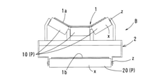
この発明の実施形態及び実験例を、図1~図5に基づいて説明する。図1及び図2は、この発明のダクタイル鋳鉄製の筒状体(ベルトコンベヤ用筒状体)Pを、無端状のコンベヤベルト1の表面に接触する駆動プーリ30、従動プーリ40、案内ローラ20,21として使用したベルトコンベヤBを示している。
An embodiment and an experimental example of the present invention will be described with reference to FIGS. 1 to 5. 1 and 2 show a
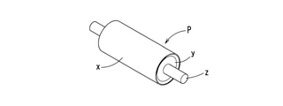
また、図3は、その駆動プーリ30、従動プーリ40、案内ローラ20,21を構成する筒状体Pの例を示している。駆動プーリ30、従動プーリ40、案内ローラ20,21を構成する各筒状体Pは、それぞれ設置される部位に応じてその径や軸方向長さが異なるが、図3では、その一例を示している。
Further, FIG. 3 shows an example of a cylindrical body P constituting the
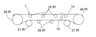
ベルトコンベヤBの装置の構成は、フレーム2に対して軸周り回転自在に支持された駆動プーリ30、従動プーリ40、案内ローラ20,21間に、無端状の帯状部材であるコンベヤベルト1が掛け渡されたものである。モータ等の駆動力によって、駆動プーリ30が軸周り回転すると、ベルト1は、駆動プーリ30と従動プーリ40と間で、図2中の矢印の方向に周回運動する。以下、コンベヤベルト1を単にベルト1と称し、搬送物が載置される上方のベルト1を搬送側ベルト1a、その下方に位置するリターン側のベルト1をリターン側ベルト1bと称する。
The device of the belt conveyor B is such that the
搬送側ベルト1aの下部には、搬送方向に沿って所要の間隔で搬送側案内ローラ10が設けられ、その搬送側案内ローラ10で、搬送物が載置されたベルト1を支えている。また、ベルト1の幅方向に沿って搬送側案内ローラ10は複数直列して設けられている。実施形態では、3つの搬送側案内ローラ10が幅方向へ直列して配置されている。また、幅方向端部に位置する搬送側案内ローラ10は、幅方向端部側へ向かって上り勾配に配置されており、搬送側ベルト1aのせり上がり、及び、搬送物がベルト1からこぼれ落ちることを防止している。
At the lower part of the transport side belt 1a, transport
リターン側ベルト1bの下部には、搬送方向に沿って所要の間隔でリターン側案内ローラ20が設けられ、そのリターン側案内ローラ20で、従動プーリ40側へ戻っていくベルト1を支えている。また、駆動プーリ30のすぐ下流側、従動プーリ40のすぐ上流側には、リターン側ベルト1bを所定の高さに案内する反転部案内ローラ21が配置されている。
A return
この実施形態のベルトコンベヤBは以上の構成であり、ベルト1が走行している状態で、従動プーリ40側に設けたシュートから搬送物がベルト1上に載置され、その搬送物が、駆動プーリ30側に搬送される。搬送物は、駆動プーリ30の直下に設けたホッパーに落下して次工程へ送り出される。
The belt conveyor B of this embodiment has the above configuration, and while the
ここで、この発明では、ベルト1の表面に接触する筒状体P、すなわち、駆動プーリ30、従動プーリ40、及び、案内ローラ10,20,21の少なくとも外周部xを、それぞれダクタイル鋳鉄製としている。
Here, in the present invention, the tubular body P in contact with the surface of the
筒状体Pは、図3に示すように、ベルト1の表面に接触する外周部xをダクタイル鋳鉄製(ダクタイル鋳鉄管)とし、その円筒状の外周部xの軸方向両端の内側に、ベアリングを介在した支持部yを固定し、その支持部yに回転軸zを取り付けている。支持部yや回転軸zの素材は、外周部xと同じダクタイル鋳鉄であってもよいが、この部分にはベルト1が接触することがないので、ダクタイル鋳鉄以外の他の鋳鉄や、普通鋼等のその他金属、あるいは、強度が確保されるならば樹脂素材でも充分である。
As shown in FIG. 3, in the tubular body P, the outer peripheral portion x in contact with the surface of the
回転軸zはフレーム2に支持され、外周部xは回転軸zの軸周りに回転自在である。なお、別の形態としては、回転軸zをフレーム2に対して軸周り回転自在に支持してもよい。この場合は、支持部yのベアリングを省略して、回転軸zと外周部xとが一体に回転する構成とすることができる。
The rotation axis z is supported by the
ダクタイル鋳鉄製とする筒状体Pは、駆動プーリ30、従動プーリ40及び搬送側案内ローラ10、リターン側案内ローラ20、反転部案内ローラ21の全部であってよいが、その一部のみとしてもよい。例えば、搬送側案内ローラ10、リターン側案内ローラ20、反転部案内ローラ21のみをダクタイル鋳鉄製とし、駆動プーリ30、従動プーリ40を他の素材としてもよい。あるいは、駆動プーリ30、従動プーリ40のみをダクタイル鋳鉄製とし、搬送側案内ローラ10、リターン側案内ローラ20、反転部案内ローラ21を他の素材としてもよい。
The tubular body P made of ductile cast iron may be all of the
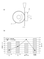
筒状体Pを構成するダクタイル鋳鉄は、黒鉛粒数が300個/mm2以上、黒鉛粒径が15μm以下、黒鉛粒が占める面積率が8%以上12%未満であるものが望ましいことが、発明者が行った実験により確認できている。その実験結果を、図4及び図5に示す。 It is desirable that the ductile cast iron constituting the tubular body P has a graphite grain number of 300 pieces / mm 2 or more, a graphite grain size of 15 μm or less, and an area ratio occupied by the graphite grains of 8% or more and less than 12%. It has been confirmed by the experiment conducted by the inventor. The experimental results are shown in FIGS. 4 and 5.
図4は、二元アブレシブ摩耗に対する耐摩耗性能の実験例である。図4(a)に示すように、回転ロール1’を軸周り回転自在に支持し、その回転ロール1’の外周に、筒状体Pに相当する試料P’を荷重a加えて当接させて、その試料P’を、矢印bのように往復動させる試験である。回転ロール1’の外周がベルト1に相当し、試料P’が筒状体Pに相当する。
FIG. 4 is an experimental example of wear resistance performance against dual elastic wear. As shown in FIG. 4A, the rotary roll 1'is rotatably supported around the axis, and the sample P'corresponding to the tubular body P is brought into contact with the outer periphery of the rotary roll 1'by applying a load a. This is a test in which the sample P'is reciprocated as shown by the arrow b. The outer circumference of the rotary roll 1'corresponds to the
回転ロール1’は試料P’に対して滑りながら軸周り回転する。実験では回転ロール1’は、試料P’の一往復毎に図中の矢印c方向に0.9度回転する。これにより、一往復毎に、常に回転ロール1’の表面の新しい部分が、試料P’に接することとなる。試験条件は、試験機がスガ式摩耗試験機、試料P’の往復回数は400回、試料P’の形状は40×50×4mm、回転ロール1’の外周にはアルミサンドペーパ#100からなる研磨紙を貼り付けている。荷重aは、1.0kgf(約9.80665N)である。
The rotary roll 1'rotates around the axis while sliding with respect to the sample P'. In the experiment, the rotary roll 1'rotates 0.9 degrees in the direction of arrow c in the figure for each round trip of the sample P'. As a result, a new portion of the surface of the rotating roll 1'is always in contact with the sample P'for each round trip. The test conditions are that the testing machine is a Suga type wear tester, the number of reciprocations of the
実験結果を、図4(b)に示す。試料P’として、フェライト系ダクタイル鋳鉄(FCD)、パーライト系ダクタイル鋳鉄(FCD)、S45C(焼き入れ材)、普通鋼(SS400)を用いている。 The experimental results are shown in FIG. 4 (b). As sample P', ferrite-based ductile cast iron (FCD), pearlite-based ductile cast iron (FCD), S45C (quenched material), and ordinary steel (SS400) are used.
図5は、三元アブレシブ摩耗に対する耐摩耗性能の実験例である。図5(a)に示すように、回転ロール1’を軸周り回転自在に支持し、その回転ロール1’の外周に、筒状体Pに相当する試料P’を荷重a加えて当接させて、その回転ロール1’を、矢印eのように回転運動させる試験である。回転ロール1’は外周にゴムが貼り付けられたラバーロールであり、そのラバーロールの外周がベルト1に相当する。また、試料P’が筒状体Pに相当する。
FIG. 5 is an experimental example of wear resistance performance against ternary elastic wear. As shown in FIG. 5A, the rotary roll 1'is rotatably supported around the axis, and the sample P'corresponding to the tubular body P is brought into contact with the outer periphery of the rotary roll 1'by applying a load a. This is a test in which the rotary roll 1'is rotated as shown by the arrow e. The rotary roll 1'is a rubber roll to which rubber is attached to the outer circumference, and the outer circumference of the rubber roll corresponds to the
試料P’は、軸周り回転する回転ロール1’の外面に摺接する。その摺接面間に、矢印fで示すように摩耗粒子を落下させている。試験条件は、試験機が同じくスガ式摩耗試験機、試料P’の形状は20×20×55mm、摩耗粒子は6号硅砂、粒子の落下速度は300g/min、粒子重量は15kgである。回転ロール1’の回転数は134rpm、試験時間は50min、荷重aは同じく1.0kgf(約9.80665N)である。
The sample P'is in sliding contact with the outer surface of the rotating roll 1'that rotates around the axis. Wear particles are dropped between the sliding contact surfaces as shown by the arrow f. The test conditions are that the testing machine is also a Suga type wear tester, the shape of the
実験結果を、図5(b)に示す。試料P’として、同じく、フェライト系ダクタイル鋳鉄(FCD)、パーライト系ダクタイル鋳鉄(FCD)、S45C(焼き入れ材)、普通鋼(SS400)を用いている。 The experimental results are shown in FIG. 5 (b). Similarly, as sample P', ferrite-based ductile cast iron (FCD), pearlite-based ductile cast iron (FCD), S45C (quenched material), and ordinary steel (SS400) are used.
上記の実験により、金型遠心鋳造法によって製造されるフェライト系ダクタイル鋳鉄管や、同じく金型遠心鋳造法によって製造されるパーライト系ダクタイル鋳鉄管の場合、三元アブレシブ摩耗が生じ得る環境下では、その素材の硬度は比較的低いにもかかわらず、S45Cの焼き入れ材と同等の耐摩耗性を発揮することが確認できた(図5(b)参照)。 According to the above experiment, in the case of ferrite-based ductile cast iron pipes manufactured by the mold centrifugal casting method and pearlite-based ductile cast iron pipes also manufactured by the mold centrifugal casting method, in an environment where ternary elastic wear can occur, Although the hardness of the material is relatively low, it was confirmed that it exhibits the same wear resistance as the hardened material of S45C (see FIG. 5 (b)).
また、二元アブレシブ摩耗が生じ得る環境下では、硬度が比較的高いS45C焼き入れ材が優れた耐摩耗性能を発揮するのに対し、フェライト系ダクタイル鋳鉄管は、SS400等の普通鋼よりも耐摩耗性が低い結果を示している(図4(b)参照)。 Further, in an environment where binary elastic wear can occur, the S45C hardened material, which has a relatively high hardness, exhibits excellent wear resistance, whereas the ferritic ductile cast iron pipe is more resistant than ordinary steel such as SS400. The result shows low wear resistance (see FIG. 4 (b)).
このことから、二元アブレシブ摩耗ではなく、特に、三元アブレシブ摩耗が生じ得る環境下において、ダクタイル鋳鉄の耐摩耗性能に関する優位性が顕著であることが確認できた。 From this, it was confirmed that the superiority of ductile cast iron in terms of wear resistance is remarkable, especially in an environment where ternary elastic wear can occur rather than binary elastic wear.
このダクタイル鋳鉄からなる筒状体Pを、三元アブレシブ摩耗が生じ得る環境下であるベルトコンベヤBの搬送側案内ローラ10や、リターン側案内ローラ20、反転部案内ローラ21に用いることにより、ベルト1との接触(摺接)による三元アブレシブ摩耗に対し、優れた耐摩耗性能を発揮できることとなる。
By using this tubular body P made of ductile cast iron for the transport
筒状体Pを構成するダクタイル鋳鉄(ダクタイル鋳鉄管)は、金型遠心鋳造法によって製造することができる。金型遠心鋳造法によって製造されるダクタイル鋳鉄管は、フェライト系ダクタイル鋳鉄や、パーライト系ダクタイル鋳鉄からなるものであり、これらは、通常のダクタイル鋳鉄と比較して、金属組織中に多数の微細な球状黒鉛が分布している。このため、アブレシブ摩耗が生じ得る環境下において、基地組織中の黒鉛が塑性流動することにより固体潤滑の役割を果たし、摩耗を抑制する効果を発揮しているのではないか、と考えられる。このため、黒鉛は、より粒径の小さいものを数多く分布させることが好ましいといえる。 The ductile cast iron (ductile cast iron pipe) constituting the tubular body P can be manufactured by a mold centrifugal casting method. Ductile cast iron pipes manufactured by the mold centrifugal casting method are composed of ferrite-based ductile cast iron and pearlite-based ductile cast iron, and these have a large number of fine particles in the metal structure as compared with ordinary ductile cast iron. Spheroidal graphite is distributed. Therefore, in an environment where elastic wear may occur, it is considered that graphite in the matrix structure plays a role of solid lubrication by plastically flowing and exerts an effect of suppressing wear. Therefore, it can be said that it is preferable to distribute a large number of graphites having a smaller particle size.
金型遠心鋳造法によって製造されたフェライト系ダクタイル鋳鉄管やパーライト系ダクタイル鋳鉄管は、上述のように、単位面積当たりの黒鉛粒数が300個/mm2以上、黒鉛粒径(平均粒径)が15μm以下、黒鉛粒が占める面積率が8%以上12%未満となっている。したがって、この条件が、三元アブレシブ摩耗に対する耐摩耗性に特に有効であるといえる。 As described above, ferrite-based ductile cast iron pipes and pearlite-based ductile cast iron pipes manufactured by the mold centrifugal casting method have a graphite grain number of 300 / mm 2 or more per unit area and a graphite particle size (average particle size). Is 15 μm or less, and the area ratio occupied by graphite grains is 8% or more and less than 12%. Therefore, it can be said that this condition is particularly effective for wear resistance against ternary elastic wear.
また、フェライト系ダクタイル鋳鉄管や、パーライト系ダクタイル鋳鉄管の場合、他の金属素材を用いた場合のように焼き入れ等の特殊な熱処理を施す必要がないため、筒状体Pを、安価に製造することが可能である。 Further, in the case of ferrite-based ductile cast iron pipes and pearlite-based ductile cast iron pipes, unlike the case of using other metal materials, there is no need to perform special heat treatment such as quenching, so the tubular body P can be made inexpensive. It is possible to manufacture.
フェライト系ダクタイル鋳鉄管とパーライト系ダクタイル鋳鉄管に関し、特に、強度が要求されるようなベルトコンベヤBの仕様、使用環境でない場合は、フェライト系ダクタイル鋳鉄管を採用し、強度が要求されるようなベルトコンベヤBの仕様、使用環境の場合は、パーライト系ダクタイル鋳鉄管を用いることが望ましい。 Regarding ferrite-based ductile cast iron pipes and pearlite-based ductile cast iron pipes, in particular, if the specifications of the belt conveyor B do not require strength, or if the environment is not used, ferrite-based ductile cast iron pipes are used and strength is required. In the case of the specifications and usage environment of the belt conveyor B, it is desirable to use a pearlite-based ductile cast iron pipe.
なお、通常のダクタイル鋳鉄では、単位面積当たりの黒鉛粒数が200個/mm2前後、黒鉛粒径が25μm前後、黒鉛粒が占める面積率が8%以上12%未満程度である。このような通常のダクタイル鋳鉄であっても、三元アブレシブ摩耗に対するある程度の耐摩耗性を発揮することは可能である。 In ordinary ductile cast iron, the number of graphite grains per unit area is about 200 / mm 2 , the graphite grain size is about 25 μm, and the area ratio occupied by the graphite grains is about 8% or more and less than 12%. Even such ordinary ductile cast iron can exhibit a certain degree of wear resistance against ternary elastic wear.
この実施形態では、筒状体Pを、円筒状の外周部xと、その外周部xの内径部に位置する支持部y、支持部yから軸方向外側へ突出する回転軸zで構成しており、筒状体Pは中空の部材となっているが、筒状体Pはこのような中空の部材を備えた構成に限定されず、例えば、円筒状の外周部xの内径部に他の部材が配置されて中空部が存在しない、いわゆる中実の部材である場合も含まれる。 In this embodiment, the tubular body P is composed of a cylindrical outer peripheral portion x, a support portion y located at the inner diameter portion of the outer peripheral portion x, and a rotation axis z projecting outward from the support portion y in the axial direction. The cylindrical body P is a hollow member, but the tubular body P is not limited to the configuration provided with such a hollow member, and for example, the inner diameter portion of the outer peripheral portion x of the cylindrical shape may be other than the inner diameter portion. It also includes the case where the member is a so-called solid member in which the member is arranged and the hollow portion does not exist.
また、ベルトコンベヤのプーリやローラだけでなく、機械部品の摺動部等においても、他の部材と接触しながら軸周り回転することで、その表面に三元アブレシブ摩耗が生じ得る種々の筒状体Pについて、その素材をダクタイル鋳鉄とすることで、三元アブレシブ摩耗を抑制する効果が期待できる。 Further, not only the pulleys and rollers of the belt conveyor, but also the sliding parts of mechanical parts, etc., rotate around the axis while in contact with other members, and various tubular shapes that can cause ternary elastic wear on the surface. By using ductile cast iron as the material for the body P, the effect of suppressing ternary elastic wear can be expected.
1 コンベヤベルト(ベルト)
1a 搬送側ベルト
1b リターン側ベルト
2 フレーム
10 搬送側案内ローラ
20 リターン側案内ローラ
21 反転部案内ローラ
30 駆動プーリ
40 従動プーリ
B ベルトコンベヤ
P 筒状体
x 外周部
y 支持部
z 回転軸
1 Conveyor belt (belt)
1a
Claims (5)
請求項2に記載の筒状体。 Claimed that the tubular body (P) is a part or all of a drive pulley (30), a driven pulley (40), and a guide roller (10, 20, 21) that come into contact with the surface of the conveyor belt (1). The tubular body according to 2.
請求項1から3のいずれか一つに記載の筒状体。 The ductile cast iron constituting the tubular body (P) has a graphite grain number of 300 pieces / mm 2 or more, a graphite grain size of 15 μm or less, and an area ratio occupied by the graphite grains of 8% or more and less than 12%. The tubular body according to any one of 3 to 3.
Priority Applications (1)
| Application Number | Priority Date | Filing Date | Title |
|---|---|---|---|
| JP2018054407A JP6991908B2 (en) | 2018-03-22 | 2018-03-22 | Cylindrical body |
Applications Claiming Priority (1)
| Application Number | Priority Date | Filing Date | Title |
|---|---|---|---|
| JP2018054407A JP6991908B2 (en) | 2018-03-22 | 2018-03-22 | Cylindrical body |
Publications (2)
| Publication Number | Publication Date |
|---|---|
| JP2019167183A JP2019167183A (en) | 2019-10-03 |
| JP6991908B2 true JP6991908B2 (en) | 2022-01-13 |
Family
ID=68107095
Family Applications (1)
| Application Number | Title | Priority Date | Filing Date |
|---|---|---|---|
| JP2018054407A Active JP6991908B2 (en) | 2018-03-22 | 2018-03-22 | Cylindrical body |
Country Status (1)
| Country | Link |
|---|---|
| JP (1) | JP6991908B2 (en) |
Families Citing this family (1)
| Publication number | Priority date | Publication date | Assignee | Title |
|---|---|---|---|---|
| JP7615998B2 (en) | 2021-10-01 | 2025-01-17 | 株式会社ダイフク | Transport conveyor and transport device equipped with said transport conveyor |
Citations (1)
| Publication number | Priority date | Publication date | Assignee | Title |
|---|---|---|---|---|
| JP2006175494A (en) | 2004-12-24 | 2006-07-06 | Mie Katan Kogyo Kk | Method for producing ductile iron ferrite ground casting |
Family Cites Families (2)
| Publication number | Priority date | Publication date | Assignee | Title |
|---|---|---|---|---|
| JPS5652174Y2 (en) * | 1978-12-26 | 1981-12-05 | ||
| JPS61159551A (en) * | 1985-01-07 | 1986-07-19 | Mitsubishi Heavy Ind Ltd | Roller for conveyance |
-
2018
- 2018-03-22 JP JP2018054407A patent/JP6991908B2/en active Active
Patent Citations (1)
| Publication number | Priority date | Publication date | Assignee | Title |
|---|---|---|---|---|
| JP2006175494A (en) | 2004-12-24 | 2006-07-06 | Mie Katan Kogyo Kk | Method for producing ductile iron ferrite ground casting |
Also Published As
| Publication number | Publication date |
|---|---|
| JP2019167183A (en) | 2019-10-03 |
Similar Documents
| Publication | Publication Date | Title |
|---|---|---|
| KR20060029215A (en) | Chain pins for hinge conveyor chains | |
| GB1571233A (en) | Arrangement for conveying and rotating material | |
| JP6991908B2 (en) | Cylindrical body | |
| US20040140160A1 (en) | Self-lubricating overhead conveyor system | |
| US4193493A (en) | Roller conveyor | |
| KR20120139652A (en) | Bush bearing | |
| KR200233688Y1 (en) | A roller for use in conveyor belt | |
| CN113993797B (en) | Carrying rollers for conveyor belt systems | |
| KR101770037B1 (en) | Friction roller for conveyor | |
| HUP0900592A2 (en) | Rubber spiral-straight guider-cleaner for rubber conveyor belts | |
| US20050023112A1 (en) | Track system for tow-line conveyors | |
| KR101703692B1 (en) | Floating seal | |
| RU2097296C1 (en) | Belt conveyor roller | |
| JP6683970B2 (en) | Sorting device | |
| CN117446418B (en) | Rotating wheel, scraping plate and material conveying device | |
| KR101956477B1 (en) | Friction roller for conveyor | |
| US1636051A (en) | Conveyer mechanism and particularly conveyer pulley supports | |
| Sapate et al. | Metallurgical investigation of failure of coal mill drag chain pin | |
| JP6403110B2 (en) | Belt conveyor with self-aligning pulley | |
| RU72948U1 (en) | BEARING TAPE ROLLER ROLLER ASSEMBLY | |
| RU224905U1 (en) | Conveyor Belt Cleaning Device | |
| CN203806536U (en) | Chain plate assembly of plate feeder | |
| CN222934606U (en) | Threaded multi-wedge belt head roller | |
| RU2487827C2 (en) | Belt conveyor roll | |
| CN202163858U (en) | Bearingless carrier roller structure |
Legal Events
| Date | Code | Title | Description |
|---|---|---|---|
| A621 | Written request for application examination |
Free format text: JAPANESE INTERMEDIATE CODE: A621 Effective date: 20201217 |
|
| A977 | Report on retrieval |
Free format text: JAPANESE INTERMEDIATE CODE: A971007 Effective date: 20210927 |
|
| TRDD | Decision of grant or rejection written | ||
| A01 | Written decision to grant a patent or to grant a registration (utility model) |
Free format text: JAPANESE INTERMEDIATE CODE: A01 Effective date: 20211109 |
|
| A61 | First payment of annual fees (during grant procedure) |
Free format text: JAPANESE INTERMEDIATE CODE: A61 Effective date: 20211208 |
|
| R150 | Certificate of patent or registration of utility model |
Ref document number: 6991908 Country of ref document: JP Free format text: JAPANESE INTERMEDIATE CODE: R150 |