JP6991663B2 - Processing method - Google Patents
Processing method Download PDFInfo
- Publication number
- JP6991663B2 JP6991663B2 JP2018000516A JP2018000516A JP6991663B2 JP 6991663 B2 JP6991663 B2 JP 6991663B2 JP 2018000516 A JP2018000516 A JP 2018000516A JP 2018000516 A JP2018000516 A JP 2018000516A JP 6991663 B2 JP6991663 B2 JP 6991663B2
- Authority
- JP
- Japan
- Prior art keywords
- workpiece
- acid
- holding
- group
- processing
- Prior art date
- Legal status (The legal status is an assumption and is not a legal conclusion. Google has not performed a legal analysis and makes no representation as to the accuracy of the status listed.)
- Active
Links
Images
Landscapes
- Finish Polishing, Edge Sharpening, And Grinding By Specific Grinding Devices (AREA)
- Mechanical Treatment Of Semiconductor (AREA)
- Grinding Of Cylindrical And Plane Surfaces (AREA)
Description
本発明は、金属を含む部材が設けられている被加工物を加工する加工方法に関する。 The present invention relates to a processing method for processing a workpiece provided with a member containing metal.
各種の電子機器等に組み込まれるデバイスチップを小型化、軽量化するために、デバイスチップへと分割される前のウェーハを薄く加工する機会が増えている。このウェーハの内部には、デバイスチップの電極や配線として機能する金属ポスト等の部材が予め埋め込まれていることも多い。 In order to reduce the size and weight of device chips incorporated in various electronic devices, there are increasing opportunities to thin wafers before they are divided into device chips. In many cases, members such as electrodes of device chips and metal posts that function as wiring are embedded in the wafer in advance.
ところが、金属ポストのような延性のある金属を含む部材は、力を加えると塑性的に引き延ばされてしまうので、研削や研磨等の方法で容易に加工できない。よって、金属を含む部材が埋め込まれた被加工物を薄くする場合には、例えば、研削等の方法で被加工物の母材を削り取った後に、バイト切削等の別の方法で金属を含む部材を加工する必要があった(例えば、特許文献1参照)。 However, a member containing a ductile metal such as a metal post is plastically stretched when a force is applied, and therefore cannot be easily processed by a method such as grinding or polishing. Therefore, when thinning a work piece in which a metal-containing member is embedded, for example, after scraping the base material of the work piece by a method such as grinding, a member containing metal is used by another method such as tool cutting. (See, for example, Patent Document 1).
しかしながら、上述のように異なる複数の加工方法を組み合わせると、工程が煩雑化して被加工物の加工に要するコストが高くなってしまうという問題がある。 However, if a plurality of different processing methods are combined as described above, there is a problem that the process becomes complicated and the cost required for processing the workpiece increases.
本発明はかかる問題点に鑑みてなされたものであり、その目的とするところは、金属を含む部材が設けられている被加工物を簡単な工程で適切に加工できる加工方法を提供することである。 The present invention has been made in view of the above problems, and an object of the present invention is to provide a processing method capable of appropriately processing a workpiece provided with a member containing a metal in a simple process. be.
本発明の一態様によれば、被加工領域に金属を含む部材が設けられている被加工物を研削砥石又は研磨パッドが装着された加工手段で加工する加工方法であって、該被加工領域を露出させた状態で被加工物を保持テーブルで保持する保持ステップと、該保持ステップを実施した後、被加工物の該被加工領域に有機酸と酸化剤とを含む加工液を供給しつつ該被加工領域を該加工手段で該被加工領域の下端の深さまで研削又は研磨して被加工物を薄くする加工ステップと、該加工ステップを実施する前に、該下端の深さを超えない深さの溝を被加工物の該被加工領域に形成する溝形成ステップと、を備える加工方法が提供される。 According to one aspect of the present invention, it is a processing method for processing a workpiece having a member containing a metal in the workpiece region by a processing means equipped with a grinding wheel or a polishing pad, wherein the workpiece region is processed. A holding step of holding the work piece on a holding table in an exposed state, and after performing the holding step, while supplying a processing liquid containing an organic acid and an oxidizing agent to the work area of the work piece. A processing step of grinding or polishing the work area to the depth of the lower end of the work area by the processing means to thin the work piece, and a processing step that does not exceed the depth of the lower end before performing the processing step. Provided is a machining method comprising a groove forming step of forming a groove of depth in the workpiece region of the workpiece.
本発明の一態様に係る加工方法では、有機酸と酸化剤とを含む加工液を供給しながら、金属を含む部材が設けられている被加工領域を研削又は研磨するので、被加工領域中の部材に含まれる金属を改質して、その延性を抑えながら被加工領域を加工できる。つまり、金属を含む部材が設けられた被加工物を簡単な工程で適切に加工できる。 In the processing method according to one aspect of the present invention, the work area provided with the metal-containing member is ground or polished while supplying the work liquid containing the organic acid and the oxidizing agent. The metal contained in the member can be modified to process the workpiece area while suppressing its ductility. That is, the workpiece provided with the member containing metal can be appropriately processed by a simple process.
また、本発明の一態様に係る加工方法では、被加工領域を研削又は研磨する前に、この被加工領域に溝を形成するので、研削又は研磨の際に加工液の保持力が高まり、被加工領域中の部材に含まれる金属の延性をより適切に抑えることができる。つまり、金属を含む部材が設けられた被加工物を簡単な工程でより適切に加工できる。 Further, in the processing method according to one aspect of the present invention, since a groove is formed in the work area before grinding or polishing the work area, the holding power of the work liquid is increased during grinding or polishing, and the work area is covered. The ductility of the metal contained in the member in the processing area can be suppressed more appropriately. That is, the workpiece provided with the member containing metal can be processed more appropriately by a simple process.
添付図面を参照して、本発明の一態様に係る実施形態について説明する。本実施形態に係る加工方法は、被加工領域に金属を含む部材が予め設けられている被加工物を加工するための加工方法であって、溝形成ステップ(図2参照)、保持ステップ(図3参照)、及び加工ステップ(図3参照)を含む。 An embodiment according to one aspect of the present invention will be described with reference to the accompanying drawings. The processing method according to the present embodiment is a processing method for processing an workpiece in which a member containing metal is provided in advance in the workpiece region, and is a groove forming step (see FIG. 2) and a holding step (FIG. 2). 3) and machining steps (see FIG. 3).
溝形成ステップでは、被加工物の被加工領域に溝を形成する。保持ステップでは、被加工領域が露出するように、研削装置(加工装置)のチャックテーブル(保持テーブル)で被加工物を保持する。加工ステップでは、被加工領域に有機酸と酸化剤とを含む加工液を供給しながら、この被加工領域を研削ユニット(加工手段)で所定の深さまで研削(加工)して被加工物を薄くする。以下、本実施形態に係る加工方法について詳述する。 In the groove forming step, a groove is formed in the work area of the work piece. In the holding step, the workpiece is held by the chuck table (holding table) of the grinding apparatus (machining apparatus) so that the workpiece area is exposed. In the machining step, while supplying a machining liquid containing an organic acid and an oxidizing agent to the work area, the work area is ground (processed) to a predetermined depth by a grinding unit (machining means) to thin the work piece. do. Hereinafter, the processing method according to this embodiment will be described in detail.
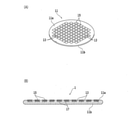
図1(A)は、本実施形態で加工される被加工物11の構成例を模式的に示す斜視図であり、図1(B)は、被加工物11の構成例を模式的に示す断面図である。図1(A)及び図1(B)に示すように、被加工物11は、例えば、シリコン(Si)等の半導体材料で構成された円盤状のウェーハである。この被加工物11の表面11a側は、交差する複数の分割予定ライン(ストリート)13によって複数の領域に区画されており、各領域には、IC(Integrated Circuit)等のデバイス15が形成されている。
FIG. 1A is a perspective view schematically showing a configuration example of the
また、被加工物11の内部には、各デバイス15の電極や配線等として機能する金属ポスト(金属を含む部材)17が埋め込まれている。この金属ポスト17は、TSV(Through Silicon Via)等と呼ばれることもある。本実施形態の加工方法では、金属ポスト17が埋め込まれた領域の少なくとも一部を含む被加工領域を加工して、被加工物11を薄くする。なお、この被加工物11を加工する前には、被加工物11の表面11a側に樹脂フィルム等の保護部材21(図2等参照)を貼付してデバイス15を保護すると良い。
Further, a metal post (member containing metal) 17 that functions as an electrode, wiring, or the like of each
本実施形態では、シリコン等の半導体材料で構成される円盤状のウェーハを被加工物11としているが、被加工物11の材質、形状、構造、大きさ等に制限はない。例えば、金属板、WL-CSP(Wafer Level Chip Size Package)用の基板、金属膜が形成されたウェーハ等、金属を含む部材が被加工領域に設けられている板等を被加工物11とすることができる。同様に、デバイス15の種類、数量、大きさ、配置等にも制限はない。また、デバイス15が形成されていない基板等を被加工物11としても良い。
In the present embodiment, the disk-shaped wafer made of a semiconductor material such as silicon is used as the
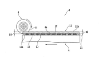
本実施形態に係る加工方法では、まず、被加工物11の被加工領域に溝を形成する溝形成ステップを行う。図2は、溝形成ステップで被加工物11の被加工領域に溝が形成される様子を模式的に示す断面図である。この溝形成ステップは、例えば、図2に示す切削装置2を用いて行われる。
In the processing method according to the present embodiment, first, a groove forming step of forming a groove in the workpiece region of the
切削装置2は、被加工物11を吸引、保持するためのチャックテーブル(保持テーブル)4を備えている。チャックテーブル4は、モータ等の回転駆動源(不図示)に連結されており、鉛直方向に概ね平行な回転軸の周りに回転する。また、チャックテーブル4の下方には、加工送り機構(不図示)が設けられており、チャックテーブル4は、この加工送り機構によって加工送り方向(第1水平方向)に移動する。
The cutting device 2 includes a chuck table (holding table) 4 for sucking and holding the
チャックテーブル4の上面の一部は、被加工物11の表面11a側(保護部材21)を吸引、保持する保持面4aになっている。保持面4aは、チャックテーブル4の内部に形成された吸引路(不図示)等を介して吸引源(不図示)に接続されている。吸引源の負圧を保持面4aに作用させることで、被加工物11は、チャックテーブル4に吸引、保持される。なお、チャックテーブル4の代わりに、機械的な方法や電気的な方法等により被加工物11を保持する別のチャックテーブル(保持テーブル)を用いても良い。
A part of the upper surface of the chuck table 4 is a
チャックテーブル4の上方には、被加工物11を切削加工するための切削ユニット6が配置されている。切削ユニット6は、加工送り方向に対して概ね垂直な回転軸となるスピンドル(不図示)を備えている。スピンドルの一端側には、環状の切削ブレード8が装着されている。スピンドルの他端側には、モータ等の回転駆動源(不図示)が連結されており、スピンドルに装着された切削ブレード8は、この回転駆動源から伝わる力によって回転する。
A
切削ユニット6は、昇降機構(不図示)及び割り出し送り機構(不図示)に支持されており、昇降機構によって切り込み送り方向(鉛直方向)に移動(昇降)するとともに、割り出し送り機構によって加工送り方向に概ね垂直な割り出し送り方向(第2水平方向)に移動する。
The
溝形成ステップでは、まず、切削装置2のチャックテーブル4で被加工物11を吸引、保持する。具体的には、被加工物11の表面11a側に貼付されている保護部材21(保護部材21が貼付されていない場合には、被加工物11の表面11a)をチャックテーブル4の保持面4aに接触させて、吸引源の負圧を作用させる。これにより、被加工物11は、被加工領域である裏面11b側が上方に露出した状態でチャックテーブル4に保持される。
In the groove forming step, first, the
次に、チャックテーブル4を回転させて、裏面11b側に予め設定されている溝形成予定ライン(不図示)を切削装置2の加工送り方向に合わせる。また、チャックテーブル4及び切削ユニット6を相対的に移動させて、この溝形成予定ラインの延長線上方に切削ブレード8の位置を合わせる。
Next, the chuck table 4 is rotated to align the groove formation schedule line (not shown) preset on the
そして、切削ブレード8の下端を、裏面11bから深さD1の位置(高さ)まで移動させる。なお、深さD1は、被加工領域の下端の深さD2(被加工物11を仕上げ厚みまで加工したときの裏面に相当する深さD2)よりも浅く設定される。すなわち、切削ブレード8の下端を、被加工領域の下端より裏面11b側に位置付ける。
Then, the lower end of the
その後、切削ブレード8を回転させながらチャックテーブル4を加工送り方向に移動させる。これにより、対象の溝形成予定ラインに沿って切削ブレード8を切り込ませ、被加工領域に溝を形成できる。これら手順を繰り返し、裏面11b側に設定されている全ての溝形成予定ラインに沿って溝が形成されると、溝形成ステップは終了する。
After that, the chuck table 4 is moved in the machining feed direction while rotating the
なお、溝形成ステップで形成される溝(溝形成予定ライン)の形状、数量、配置、深さ等は、後の加工ステップにおいて用いられる加工液の保持力を高めることができる範囲内で適切に設定される。ただし、溝の具体的な形状、数量、配置、深さ等に特段の制限はない。 The shape, quantity, arrangement, depth, etc. of the grooves (planned groove formation lines) formed in the groove forming step are appropriately set within a range that can increase the holding power of the machining fluid used in the subsequent machining step. Set. However, there are no particular restrictions on the specific shape, quantity, arrangement, depth, etc. of the grooves.
例えば、溝の端部を被加工物11の外周縁より内側に配置しても良い。この場合には、溝の端部から加工液が流出し難くなるので、加工液の保持力が更に高まる。また、溝の深さを、金属ポスト17の上端の深さ(金属ポスト17の裏面11b側の端の深さ)より深く設定すると良い。これにより、溝に保持される加工液を金属ポスト17に作用させ易くなる。また、例えば、分割予定ライン13に沿って溝を配置しても良いし、分割予定ライン13とは関係のない位置に溝を配置しても良い。
For example, the end portion of the groove may be arranged inside the outer peripheral edge of the
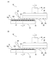
溝形成ステップの後には、被加工領域である裏面11b側が露出するように、研削装置(加工装置)のチャックテーブル(保持テーブル)で被加工物11を保持する保持ステップを行う。図3(A)及び図3(B)は、被加工物11の被加工領域が研削される様子を模式的に示す断面図である。この保持ステップは、例えば、図3に示す研削装置(加工装置)12を用いて行われる。
After the groove forming step, a holding step of holding the
研削装置12は、被加工物11を吸引、保持するためのチャックテーブル(保持テーブル)14を備えている。チャックテーブル14は、モータ等の回転駆動源(不図示)に連結されており、鉛直方向に概ね平行な回転軸の周りに回転する。また、チャックテーブル14の下方には、移動機構(不図示)が設けられており、チャックテーブル14は、この移動機構によって水平方向に移動する。
The grinding
チャックテーブル14の上面の一部は、被加工物11の表面11a側(保護部材21)を吸引、保持する保持面14aになっている。保持面14aは、チャックテーブル14の内部に形成された吸引路(不図示)等を介して吸引源(不図示)に接続されている。吸引源の負圧を保持面14aに作用させることで、被加工物11は、チャックテーブル14に吸引、保持される。なお、チャックテーブル14の代わりに、機械的な方法や電気的な方法等により被加工物11を保持する別のチャックテーブル(保持テーブル)を用いても良い。
A part of the upper surface of the chuck table 14 is a holding
チャックテーブル14の上方には、研削ユニット(加工手段)16が配置されている。研削ユニット16は、昇降機構(不図示)によって支持されたスピンドルハウジング(不図示)を備えている。スピンドルハウジングには、鉛直方向に概ね平行な回転軸となるスピンドル18が収容されており、スピンドル18の下端部には、円盤状のマウント20が固定されている。
A grinding unit (machining means) 16 is arranged above the chuck table 14. The grinding
マウント20の下面には、マウント20と概ね径が等しい円盤状の研削ホイール22が装着されている。研削ホイール22は、ステンレス、アルミニウム等の金属材料で形成されたホイール基台24を備えている。ホイール基台24の下面には、複数の研削砥石26が環状に配列されている。
A disk-shaped
スピンドル18の上端側(基端側)には、モータ等の回転駆動源(不図示)が連結されており、研削ホイール22は、この回転駆動源から伝わる力によって回転する。研削ユニット16の近傍(又は、内部)には、有機酸と酸化剤とを含む加工液(研削液)23を被加工物11等に対して供給するためのノズル28が設けられている。
A rotation drive source (not shown) such as a motor is connected to the upper end side (base end side) of the
保持ステップでは、まず、研削装置12のチャックテーブル14で被加工物11を吸引、保持する。具体的には、被加工物11の表面11a側に貼付されている保護部材21(保護部材21が貼付されていない場合には、被加工物11の表面11a)をチャックテーブル14の保持面14aに接触させて、吸引源の負圧を作用させる。これにより、被加工物11は、被加工領域である裏面11b側が上方に露出した状態でチャックテーブル14に保持される。
In the holding step, first, the
保持ステップの後には、被加工領域を研削ユニット(加工手段)で所定の深さまで研削(加工)して被加工物を薄くする加工ステップを行う。加工ステップは、引き続き研削装置12を用いて行われる。具体的には、まず、被加工物11を保持したチャックテーブル14を研削ユニット16の下方に移動させる。
After the holding step, a machining step is performed in which the workpiece area is ground (processed) to a predetermined depth by a grinding unit (machining means) to thin the workpiece. The machining step is continued using the grinding
そして、図3(A)に示すように、チャックテーブル14と研削ホイール22とをそれぞれ回転させて、有機酸と酸化剤とを含む加工液23を被加工領域である被加工物11の裏面11b側に供給しながら、スピンドルハウジング(スピンドル18、研削ホイール22)を下降させる。
Then, as shown in FIG. 3A, the chuck table 14 and the
スピンドルハウジングの下降速度(下降量)は、研削砥石26の下面が適切な力でウェーハ11の裏面11b側に押し当てられるように調整される。これにより、被加工領域である裏面11b側を研削して被加工物11を薄くできる。図3(B)に示すように、被加工物11が所定の仕上げ厚みまで薄くなると、加工ステップは終了する。
The descending speed (descending amount) of the spindle housing is adjusted so that the lower surface of the
本実施形態では、加工液23に有機酸を含ませているので、被加工領域中の金属ポスト17を改質して、その延性を抑えることができる。また、加工液23に酸化剤を含ませることで、金属ポスト17の表面が酸化し易くなる。その結果、被加工領域中の金属ポスト17の延性を十分に下げて、金属ポスト17が引き延ばされるのを防止できる。
In the present embodiment, since the
加工液23に含まれる有機酸としては、例えば、分子内に少なくとも1つのカルボキシル基と少なくとも1つのアミノ基とを有する化合物を用いることができる。この場合、アミノ基のうち少なくとも1つは、2級又は3級のアミノ基であると好ましい。また、有機酸として用いる化合物は、置換基を有していてもよい。
As the organic acid contained in the
有機酸として用いることのできるアミノ酸としては、グリシン、ジヒドロキシエチルグリシン、グリシルグリシン、ヒドロキシエチルグリシン、N-メチルグリシン、β-アラニン、L-アラニン、L-2-アミノ酪酸、L-ノルバリン、L-バリン、L-ロイシン、L-ノルロイシン、L-アロイソロイシン、L-イソロイシン、L-フェニルアラニン、L-プロリン、サルコシン、L-オルニチン、L-リシン、タウリン、L-セリン、L-トレオニン、L-アロトレオニン、L-ホモセリン、L-チロキシン、L-チロシン、3,5-ジヨード-L-チロシン、β-(3,4-ジヒドロキシフェニル)-L-アラニン、4-ヒドロキシ-L-プロリン、L-システィン、L-メチオニン、L-エチオニン、L-ランチオニン、L-シスタチオニン、L-シスチン、L-システィン酸、L-グルタミン酸、L-アスパラギン酸、S-(カルボキシメチル)-L-システィン、4-アミノ酪酸、L-アスパラギン、L-グルタミン、アザセリン、L-カナバニン、L-シトルリン、L-アルギニン、δ-ヒドロキシ-L-リシン、クレアチン、L-キヌレニン、L-ヒスチジン、1-メチル-L-ヒスチジン、3-メチル-L-ヒスチジン、L-トリプトファン、アクチノマイシンC1、エルゴチオネイン、アパミン、アンギオテンシンI、アンギオテンシンII及びアンチパイン等が挙げられる。中でも、グリシン、L-アラニン、L-プロリン、L-ヒスチジン、L-リシン、ジヒドロキシエチルグリシンが好ましい。 Amino acids that can be used as organic acids include glycine, dihydroxyethylglycine, glycylglycine, hydroxyethylglycine, N-methylglycine, β-alanine, L-alanine, L-2-aminobutyric acid, L-norvaline, and L. -Valin, L-leucine, L-norleucine, L-alloisoleucine, L-isoleucine, L-phenylalanine, L-proline, sarcosine, L-ornithine, L-lysine, taurine, L-serine, L-threonine, L- Allothreonine, L-homoseline, L-tyroxin, L-tyrosine, 3,5-diiodo-L-tyrosine, β- (3,4-dihydroxyphenyl) -L-alanine, 4-hydroxy-L-proline, L- Cistine, L-methionine, L-ethionine, L-lanthionine, L-cystathionine, L-cystine, L-cystine acid, L-glutamic acid, L-asparaginic acid, S- (carboxymethyl) -L-cystine, 4-amino Butyric acid, L-asparagin, L-glutamine, azaserine, L-canabanin, L-citrulin, L-arginine, δ-hydroxy-L-lycine, creatine, L-quinurenin, L-histidine, 1-methyl-L-histidine, Examples thereof include 3-methyl-L-histidine, L-tryptophan, actinomycin C1, ergothionine, apamine, angiotensin I, angiotensin II and antipine. Of these, glycine, L-alanine, L-proline, L-histidine, L-lysine, and dihydroxyethylglycine are preferable.
また、有機酸として用いることのできるアミノポリ酸としては、イミノジ酢酸、ニトリロ三酢酸、ジエチレントリアミン五酢酸、エチレンジアミン四酢酸、ヒドロキシエチルイミノジ酢酸、ニトリロトリスメチレンホスホン酸、エチレンジアミン-N,N,N’,N’-テトラメチレンスルホン酸、1,2-ジアミノプロパン四酢酸、グリコールエーテルジアミン四酢酸、トランスシクロヘキサンジアミン四酢酸、エチレンジアミンオルトヒドロキシフェニル酢酸、エチレンジアミンジ琥珀酸(SS体)、β-アラニンジ酢酸、N-(2-カルボキシラートエチル)-L-アスパラギン酸、N,N’-ビス(2-ヒドロキシベンジル)エチレンジアミン-N,N’-ジ酢酸等が挙げられる。 Examples of aminopoly acids that can be used as organic acids include iminodiacetic acid, nitrilotriacetic acid, diethylenetriaminepentacetic acid, ethylenediaminetetraacetic acid, hydroxyethyliminodiacetic acid, nitrilotrismethylenephosphonic acid, ethylenediamine-N, N, N', N'-tetramethylenesulfonic acid, 1,2-diaminopropanetetraacetic acid, glycol etherdiaminetetraacetic acid, transcyclohexanediaminetetraacetic acid, ethylenediamine orthohydroxyphenylacetic acid, ethylenediaminedi-auric acid (SS form), β-alaninediacetic acid, N -(2-Carboxylateethyl) -L-aspartic acid, N, N'-bis (2-hydroxybenzyl) ethylenediamine-N, N'-diacetic acid and the like can be mentioned.
更に、有機酸として用いることのできるカルボン酸としては、ギ酸、グリコール酸、プロピオン酸、酢酸、酪酸、吉草酸、ヘキサン酸、シュウ酸、マロン酸、グルタル酸、アジピン酸、リンゴ酸、コハク酸、ピメリン酸、メルカプト酢酸、グリオキシル酸、クロロ酢酸、ピルビン酸、アセト酢酸、グルタル酸等の飽和カルボン酸や、アクリル酸、メタクリル酸、クロトン酸、フマル酸、マレイン酸、メサコン酸、シトラコン酸、アコニット酸等の不飽和カルボン酸、安息香酸類、トルイル酸、フタル酸類、ナフトエ酸類、ピロメット酸、ナフタル酸等の環状不飽和カルボン酸等が挙げられる。 Further, carboxylic acids that can be used as organic acids include formic acid, glycolic acid, propionic acid, acetic acid, butyric acid, valeric acid, hexanoic acid, oxalic acid, malonic acid, glutaric acid, adipic acid, malic acid, succinic acid, and the like. Saturated carboxylic acids such as pimelic acid, mercaptoacetic acid, glyoxylic acid, chloroacetic acid, pyruvate, acetacetic acid, glutaric acid, acrylic acid, methacrylic acid, crotonic acid, fumaric acid, maleic acid, mesaconic acid, citraconic acid, aconitic acid. And the like, unsaturated carboxylic acids such as benzoic acids, toluyl acids, phthal acids, naphthoic acids, pyrrometic acids, cyclic unsaturated carboxylic acids such as naphthalic acid and the like can be mentioned.
加工液23に含まれる酸化剤としては、例えば、過酸化水素、過酸化物、硝酸塩、ヨウ素酸塩、過ヨウ素酸塩、次亜塩素酸塩、亜塩素酸塩、塩素酸塩、過塩素酸塩、過硫酸塩、重クロム酸塩、過マンガン酸塩、セリウム酸塩、バナジン酸塩、オゾン水および銀(II)塩、鉄(III)塩や、その有機錯塩等を用いることができる。
Examples of the oxidizing agent contained in the
また、加工液23には、防食剤が混合されても良い。防食剤を混合することで、被加工物11に含まれる金属の腐食(溶出)を防止できる。防食剤としては、例えば、分子内に3つ以上の窒素原子を有し、且つ、縮環構造を有する複素芳香環化合物、又は、分子内に4つ以上の窒素原子を有する複素芳香環化合物を用いることが好ましい。更に、芳香環化合物は、カルボキシル基、スルホ基、ヒドロキシ基、アルコキシ基を含むことが好ましい。具体的には、テトラゾール誘導体、1,2,3-トリアゾール誘導体、及び1,2,4-トリアゾール誘導体であることが好ましい。
Further, the
防食剤として用いることのできるテトラゾール誘導体としては、テトラゾール環を形成する窒素原子上に置換基を有さず、且つ、テトラゾールの5位に、スルホ基、アミノ基、カルバモイル基、カルボンアミド基、スルファモイル基、及びスルホンアミド基からなる群より選択された置換基、又は、ヒドロキシ基、カルボキシ基、スルホ基、アミノ基、カルバモイル基、カルボンアミド基、スルファモイル基、及びスルホンアミド基からなる群より選択された少なくとも1つの置換基で置換されたアルキル基が導入されたものが挙げられる。 The tetrazole derivative that can be used as an anticorrosion agent has no substituent on the nitrogen atom forming the tetrazole ring, and has a sulfo group, an amino group, a carbamoyl group, a carboxylic amide group, and a sulfamoyl at the 5-position of the tetrazole. A substituent selected from the group consisting of a group and a sulfonamide group, or a group consisting of a hydroxy group, a carboxy group, a sulfo group, an amino group, a carbamoyl group, a carboxylicamide group, a sulfamoyl group, and a sulfonamide group. Introducing an alkyl group substituted with at least one substituent can be mentioned.
また、防食剤として用いることのできる1,2,3-トリアゾール誘導体としては、1,2,3-トリアゾール環を形成する窒素原子上に置換基を有さず、且つ、1,2,3-トリアゾールの4位及び/又は5位に、ヒドロキシ基、カルボキシ基、スルホ基、アミノ基、カルバモイル基、カルボンアミド基、スルファモイル基、及びスルホンアミド基からなる群より選択された置換基、或いは、ヒドロキシ基、カルボキシ基、スルホ基、アミノ基、カルバモイル基、カルボンアミド基、スルファモイル基、及びスルホンアミド基からなる群より選択された少なくとも1つの置換基で置換されたアルキル基又はアリール基が導入されたものが挙げられる。 Further, the 1,2,3-triazole derivative that can be used as an anticorrosion agent has no substituent on the nitrogen atom forming the 1,2,3-triazole ring and has 1,2,3-. A substituent selected from the group consisting of a hydroxy group, a carboxy group, a sulfo group, an amino group, a carbamoyl group, a carboxylicamide group, a sulfamoyl group, and a sulfonamide group at the 4-position and / or 5-position of triazole, or hydroxy. An alkyl or aryl group substituted with at least one substituent selected from the group consisting of a group, a carboxy group, a sulfo group, an amino group, a carbamoyl group, a carboxylic amide group, a sulfamoyl group, and a sulfon amide group was introduced. Things can be mentioned.
また、防食剤として用いることのできる1,2,4-トリアゾール誘導体としては、1,2,4-トリアゾール環を形成する窒素原子上に置換基を有さず、且つ、1,2,4-トリアゾールの2位及び/又は5位に、スルホ基、カルバモイル基、カルボンアミド基、スルファモイル基、及びスルホンアミド基からなる群より選択された置換基、或いは、ヒドロキシ基、カルボキシ基、スルホ基、アミノ基、カルバモイル基、カルボンアミド基、スルファモイル基、及びスルホンアミド基からなる群より選択された少なくとも1つの置換基で置換されたアルキル基又はアリール基が導入されたものが挙げられる。 Further, the 1,2,4-triazole derivative that can be used as an anticorrosion agent has no substituent on the nitrogen atom forming the 1,2,4-triazole ring and has 1,2,4- Substituents selected from the group consisting of a sulfo group, a carbamoyl group, a carboxylic amide group, a sulfamoyl group, and a sulfonamide group, or a hydroxy group, a carboxy group, a sulfo group, and an amino at the 2-position and / or 5-position of triazole. Examples thereof include those introduced with an alkyl group or an aryl group substituted with at least one substituent selected from the group consisting of a group, a carbamoyl group, a carboxylic amide group, a sulfamoyl group, and a sulfonamide group.
本実施形態に係る加工方法では、有機酸と酸化剤とを含む加工液23を供給しながら、金属ポスト(金属を含む部材)17が設けられている被加工領域を研削するので、被加工領域中の金属ポスト17を構成する金属を改質して、その延性を抑えながら被加工領域を加工できる。つまり、金属を含む部材が設けられた被加工物11を簡単な工程で適切に加工できる。
In the processing method according to the present embodiment, the processed region provided with the metal post (member containing metal) 17 is ground while supplying the
また、本実施形態に係る加工方法では、被加工領域を研削する前に、この被加工領域に溝を形成するので、研削の際に加工液23の保持力が高まり、被加工領域中の金属ポスト23を構成する金属の延性をより適切に抑えることができる。つまり、金属を含む部材が設けられた被加工物11を簡単な工程でより適切に加工できる。
Further, in the processing method according to the present embodiment, since the groove is formed in the work area before grinding the work area, the holding force of the
なお、本発明は、上記実施形態の記載に制限されず種々変更して実施可能である。例えば、上記実施形態では、研削砥石26を含む研削ホイール22が装着された研削ユニット(加工手段)16で被加工物11を研削する場合について説明したが、例えば、研磨パッドが装着された研磨ユニット(加工手段)で被加工物11を研磨する場合にも、本発明を適用できる。
The present invention is not limited to the description of the above embodiment, and can be modified in various ways. For example, in the above embodiment, the case where the
また、上記実施形態では、被加工物11の被加工領域に切削ブレード8を切り込ませる方法で溝を形成しているが、例えば、レーザビームを用いるアブレーション加工によって溝を形成しても良い。
Further, in the above embodiment, the groove is formed by cutting the
また、上記実施形態では、加工液23を供給しながら被加工物11を研削する加工ステップを例示しているが、例えば、加工ステップは、純水を供給しながら被加工物11を研削する第1加工ステップと、加工液23を供給しながら被加工物11を研削する第2加工ステップとを含んでも良い。
Further, in the above embodiment, the machining step of grinding the
この場合には、例えば、上述した金属ポスト17が露出する直前の高さ(厚み)まで、純水を供給しながら被加工物11を研削する第1加工ステップを行い、その後、上述した加工液23を供給しながら被加工物11を研削する第2加工ステップを行う。なお、金属ポスト17が露出する直前の高さ(厚み)は、例えば、金属ポスト17の高さのばらつきや、保護部材21の厚みのばらつき、チャックテーブル14の保持面14aの平坦度等に応じて決定できる。
In this case, for example, the first processing step of grinding the
その他、上記実施形態に係る構造、方法等は、本発明の目的の範囲を逸脱しない限りにおいて適宜変更して実施できる。 In addition, the structure, method, and the like according to the above-described embodiment can be appropriately modified and implemented as long as they do not deviate from the scope of the object of the present invention.
11 被加工物
11a 表面
11b 裏面
13 分割予定ライン(ストリート)
15 デバイス
17 金属ポスト(金属を含む部材)
21 保護部材
23 加工液(研削液)
2 切削装置
4 チャックテーブル(保持テーブル)
4a 保持面
6 切削ユニット
8 切削ブレード
12 研削装置(加工装置)
14 チャックテーブル(保持テーブル)
14a 保持面
16 研削ユニット(加工手段)
18 スピンドル
20 マウント
22 研削ホイール
24 ホイール基台
26 研削砥石
28 ノズル
11
15
21
2 Cutting equipment 4 Chuck table (holding table)
14 Chuck table (holding table)
14a Holding surface 16 Grinding unit (processing means)
18
Claims (1)
該被加工領域を露出させた状態で被加工物を保持テーブルで保持する保持ステップと、
該保持ステップを実施した後、被加工物の該被加工領域に有機酸と酸化剤とを含む加工液を供給しつつ該被加工領域を該加工手段で該被加工領域の下端の深さまで研削又は研磨して被加工物を薄くする加工ステップと、
該加工ステップを実施する前に、該下端の深さを超えない深さの溝を被加工物の該被加工領域に形成する溝形成ステップと、を備えることを特徴とする加工方法。 It is a processing method for processing a work piece provided with a member containing metal in the work area by a processing means equipped with a grinding wheel or a polishing pad.
A holding step of holding the work piece on a holding table with the work area exposed, and a holding step.
After performing the holding step, the work area is ground to the depth of the lower end of the work area by the work means while supplying a work liquid containing an organic acid and an oxidizing agent to the work area of the work piece. Or the processing step of polishing to thin the work piece,
A processing method comprising: a groove forming step for forming a groove having a depth not exceeding the depth of the lower end in the processed region of the workpiece before carrying out the machining step.
Priority Applications (1)
| Application Number | Priority Date | Filing Date | Title |
|---|---|---|---|
| JP2018000516A JP6991663B2 (en) | 2018-01-05 | 2018-01-05 | Processing method |
Applications Claiming Priority (1)
| Application Number | Priority Date | Filing Date | Title |
|---|---|---|---|
| JP2018000516A JP6991663B2 (en) | 2018-01-05 | 2018-01-05 | Processing method |
Publications (2)
| Publication Number | Publication Date |
|---|---|
| JP2019119006A JP2019119006A (en) | 2019-07-22 |
| JP6991663B2 true JP6991663B2 (en) | 2022-01-12 |
Family
ID=67305816
Family Applications (1)
| Application Number | Title | Priority Date | Filing Date |
|---|---|---|---|
| JP2018000516A Active JP6991663B2 (en) | 2018-01-05 | 2018-01-05 | Processing method |
Country Status (1)
| Country | Link |
|---|---|
| JP (1) | JP6991663B2 (en) |
Families Citing this family (2)
| Publication number | Priority date | Publication date | Assignee | Title |
|---|---|---|---|---|
| JP7451043B2 (en) * | 2020-06-05 | 2024-03-18 | 株式会社ディスコ | Grinding method and grinding device for workpiece |
| JP7684178B2 (en) * | 2021-09-30 | 2025-05-27 | 株式会社ディスコ | Method for grinding a workpiece |
Citations (6)
| Publication number | Priority date | Publication date | Assignee | Title |
|---|---|---|---|---|
| US20020197935A1 (en) | 2000-02-14 | 2002-12-26 | Mueller Brian L. | Method of polishing a substrate |
| JP2004022697A (en) | 2002-06-14 | 2004-01-22 | Oki Electric Ind Co Ltd | Method for manufacturing semiconductor device |
| JP2014220443A (en) | 2013-05-10 | 2014-11-20 | 株式会社ディスコ | Method for processing package substrate |
| JP2015082627A (en) | 2013-10-24 | 2015-04-27 | 株式会社ディスコ | Processing method of package substrate |
| JP2015171748A (en) | 2014-03-12 | 2015-10-01 | 株式会社ディスコ | Processing method |
| JP2016069522A (en) | 2014-09-30 | 2016-05-09 | 株式会社フジミインコーポレーテッド | Composition |
Family Cites Families (1)
| Publication number | Priority date | Publication date | Assignee | Title |
|---|---|---|---|---|
| JPH08148454A (en) * | 1994-11-22 | 1996-06-07 | Sony Corp | Substrate polishing method |
-
2018
- 2018-01-05 JP JP2018000516A patent/JP6991663B2/en active Active
Patent Citations (6)
| Publication number | Priority date | Publication date | Assignee | Title |
|---|---|---|---|---|
| US20020197935A1 (en) | 2000-02-14 | 2002-12-26 | Mueller Brian L. | Method of polishing a substrate |
| JP2004022697A (en) | 2002-06-14 | 2004-01-22 | Oki Electric Ind Co Ltd | Method for manufacturing semiconductor device |
| JP2014220443A (en) | 2013-05-10 | 2014-11-20 | 株式会社ディスコ | Method for processing package substrate |
| JP2015082627A (en) | 2013-10-24 | 2015-04-27 | 株式会社ディスコ | Processing method of package substrate |
| JP2015171748A (en) | 2014-03-12 | 2015-10-01 | 株式会社ディスコ | Processing method |
| JP2016069522A (en) | 2014-09-30 | 2016-05-09 | 株式会社フジミインコーポレーテッド | Composition |
Also Published As
| Publication number | Publication date |
|---|---|
| JP2019119006A (en) | 2019-07-22 |
Similar Documents
| Publication | Publication Date | Title |
|---|---|---|
| US9349647B2 (en) | Cutting method | |
| JP6890885B2 (en) | Processing method | |
| CN104916582B (en) | processing methods | |
| JP6991663B2 (en) | Processing method | |
| JP6824581B2 (en) | Processing method | |
| KR102422912B1 (en) | Processing method | |
| KR20180112691A (en) | Processing method | |
| CN108687978B (en) | Processing method | |
| JP6949421B2 (en) | Processing method | |
| JP6385085B2 (en) | Tool cutting method | |
| US10468302B2 (en) | Workpiece processing method | |
| KR20180112683A (en) | Processing method | |
| KR20180112685A (en) | Processing method | |
| JP2025091496A (en) | Additive for processing water and processing method for processed material | |
| KR20180112684A (en) | Processing method |
Legal Events
| Date | Code | Title | Description |
|---|---|---|---|
| A621 | Written request for application examination |
Free format text: JAPANESE INTERMEDIATE CODE: A621 Effective date: 20201112 |
|
| A977 | Report on retrieval |
Free format text: JAPANESE INTERMEDIATE CODE: A971007 Effective date: 20211110 |
|
| A131 | Notification of reasons for refusal |
Free format text: JAPANESE INTERMEDIATE CODE: A131 Effective date: 20211116 |
|
| A521 | Request for written amendment filed |
Free format text: JAPANESE INTERMEDIATE CODE: A523 Effective date: 20211119 |
|
| TRDD | Decision of grant or rejection written | ||
| A01 | Written decision to grant a patent or to grant a registration (utility model) |
Free format text: JAPANESE INTERMEDIATE CODE: A01 Effective date: 20211207 |
|
| A61 | First payment of annual fees (during grant procedure) |
Free format text: JAPANESE INTERMEDIATE CODE: A61 Effective date: 20211207 |
|
| R150 | Certificate of patent or registration of utility model |
Ref document number: 6991663 Country of ref document: JP Free format text: JAPANESE INTERMEDIATE CODE: R150 |
|
| R250 | Receipt of annual fees |
Free format text: JAPANESE INTERMEDIATE CODE: R250 |
|
| R250 | Receipt of annual fees |
Free format text: JAPANESE INTERMEDIATE CODE: R250 |