JP6987499B2 - Light source device and projection type display device - Google Patents
Light source device and projection type display device Download PDFInfo
- Publication number
- JP6987499B2 JP6987499B2 JP2016247786A JP2016247786A JP6987499B2 JP 6987499 B2 JP6987499 B2 JP 6987499B2 JP 2016247786 A JP2016247786 A JP 2016247786A JP 2016247786 A JP2016247786 A JP 2016247786A JP 6987499 B2 JP6987499 B2 JP 6987499B2
- Authority
- JP
- Japan
- Prior art keywords
- light source
- source device
- phosphor wheel
- light
- phosphor
- Prior art date
- Legal status (The legal status is an assumption and is not a legal conclusion. Google has not performed a legal analysis and makes no representation as to the accuracy of the status listed.)
- Active
Links
Images


Classifications
-
- G—PHYSICS
- G03—PHOTOGRAPHY; CINEMATOGRAPHY; ANALOGOUS TECHNIQUES USING WAVES OTHER THAN OPTICAL WAVES; ELECTROGRAPHY; HOLOGRAPHY
- G03B—APPARATUS OR ARRANGEMENTS FOR TAKING PHOTOGRAPHS OR FOR PROJECTING OR VIEWING THEM; APPARATUS OR ARRANGEMENTS EMPLOYING ANALOGOUS TECHNIQUES USING WAVES OTHER THAN OPTICAL WAVES; ACCESSORIES THEREFOR
- G03B21/00—Projectors or projection-type viewers; Accessories therefor
- G03B21/14—Details
- G03B21/20—Lamp housings
- G03B21/2006—Lamp housings characterised by the light source
- G03B21/2033—LED or laser light sources
- G03B21/204—LED or laser light sources using secondary light emission, e.g. luminescence or fluorescence
-
- G—PHYSICS
- G02—OPTICS
- G02B—OPTICAL ELEMENTS, SYSTEMS OR APPARATUS
- G02B26/00—Optical devices or arrangements for the control of light using movable or deformable optical elements
- G02B26/007—Optical devices or arrangements for the control of light using movable or deformable optical elements the movable or deformable optical element controlling the colour, i.e. a spectral characteristic, of the light
- G02B26/008—Optical devices or arrangements for the control of light using movable or deformable optical elements the movable or deformable optical element controlling the colour, i.e. a spectral characteristic, of the light in the form of devices for effecting sequential colour changes, e.g. colour wheels
-
- G—PHYSICS
- G03—PHOTOGRAPHY; CINEMATOGRAPHY; ANALOGOUS TECHNIQUES USING WAVES OTHER THAN OPTICAL WAVES; ELECTROGRAPHY; HOLOGRAPHY
- G03B—APPARATUS OR ARRANGEMENTS FOR TAKING PHOTOGRAPHS OR FOR PROJECTING OR VIEWING THEM; APPARATUS OR ARRANGEMENTS EMPLOYING ANALOGOUS TECHNIQUES USING WAVES OTHER THAN OPTICAL WAVES; ACCESSORIES THEREFOR
- G03B21/00—Projectors or projection-type viewers; Accessories therefor
- G03B21/14—Details
- G03B21/16—Cooling; Preventing overheating
-
- G—PHYSICS
- G03—PHOTOGRAPHY; CINEMATOGRAPHY; ANALOGOUS TECHNIQUES USING WAVES OTHER THAN OPTICAL WAVES; ELECTROGRAPHY; HOLOGRAPHY
- G03B—APPARATUS OR ARRANGEMENTS FOR TAKING PHOTOGRAPHS OR FOR PROJECTING OR VIEWING THEM; APPARATUS OR ARRANGEMENTS EMPLOYING ANALOGOUS TECHNIQUES USING WAVES OTHER THAN OPTICAL WAVES; ACCESSORIES THEREFOR
- G03B21/00—Projectors or projection-type viewers; Accessories therefor
- G03B21/14—Details
- G03B21/20—Lamp housings
- G03B21/2066—Reflectors in illumination beam
Description
本発明は、励起光により蛍光体を励起させて得られた蛍光光を利用する光源装置に関する。 The present invention relates to a light source device that utilizes fluorescent light obtained by exciting a phosphor with excitation light.
近年、高耐久性かつ高輝度の観点から、レーザ光源を備えた光源装置が提案されている。このような光源装置は、レーザ光源から射出された光を、波長変換のための蛍光体層を含む蛍光体ホイール上で集光させる。また、蛍光体ホイールを用いた光源装置では、蛍光体層の温度が局所的な上昇に伴う波長変換効率の低下およびバインダ(樹脂材料)の劣化を抑制するため、モータを用いて蛍光体ホイールを回転させる必要がある。 In recent years, a light source device including a laser light source has been proposed from the viewpoint of high durability and high brightness. Such a light source device collects the light emitted from the laser light source on a phosphor wheel including a phosphor layer for wavelength conversion. Further, in the light source device using the phosphor wheel, in order to suppress the decrease in wavelength conversion efficiency and the deterioration of the binder (resin material) due to the local rise in the temperature of the phosphor layer, the phosphor wheel is mounted by using a motor. Need to rotate.
ところで、蛍光体層の表面に埃などの異物が付着すると、蛍光体層に到達する光量が低下して波長変換効率が低下する。このため、蛍光体ホイールを密閉空間内に収納する必要がある。一方、蛍光体ホイールを密閉空間内に収納すると、蛍光体ホイールの温度上昇を抑制することが困難になる。 By the way, when foreign matter such as dust adheres to the surface of the phosphor layer, the amount of light reaching the phosphor layer decreases and the wavelength conversion efficiency decreases. Therefore, it is necessary to store the phosphor wheel in a closed space. On the other hand, if the phosphor wheel is housed in a closed space, it becomes difficult to suppress the temperature rise of the phosphor wheel.
そこで特許文献1には、蛍光体ホイールに羽根部を設けてケーシングの内部の密閉空間内の空気流動を促す構成を有することにより、ケーシングの内部の蛍光体ホイールによる発熱を外部へ放熱する光源装置が開示されている。
Therefore,
しかしながら、特許文献1に開示された構成では、蛍光体ホイールによる発熱をケーシングの外部へ放熱することはできるが、蛍光体ホイールを回転させるためのモータの負荷が増大し、騒音の発生が増大する。
However, in the configuration disclosed in
そこで本発明は、蛍光体ホイールを回転させるためのモータの負荷の増大を抑制しつつ、蛍光体ホイールによる発熱をケーシングの外部へ効率的に放熱することが可能な光源装置および投射型表示装置を提供することを目的とする。 Therefore, the present invention provides a light source device and a projection type display device capable of efficiently dissipating heat generated by the phosphor wheel to the outside of the casing while suppressing an increase in the load of a motor for rotating the phosphor wheel. The purpose is to provide.
本発明の一側面としての光源装置は、光源と、回転軸を中心として回転可能に保持された円板と、前記円板に設けられた、前記光源からの光の波長を変換する波長変換部材と、前記円板を収納する収納部材を有し、前記収納部材は、該収納部材の内部に、前記回転軸を中心とする同心円状の複数の円筒面からなる壁部を備え、前記円筒面はそれぞれ複数のスリットを有する。
The light source device as one aspect of the present invention includes a light source, a disk rotatably held around a rotation axis, and a wavelength conversion member provided on the disk to convert the wavelength of light from the light source. When, having a housing member for accommodating the disc, the housing member, the interior of the housing member includes a wall portion consisting of a plurality of concentric cylindrical surface centered on the said rotation axis, said cylindrical surface Each has a plurality of slits .
本発明の他の側面としての投射型表示装置は、前記光源装置と、前記光源装置から射出された光を変調して投射する光学系を保持可能な筺体を有する。
The projection type display device as another aspect of the present invention has the light source device and a housing capable of holding an optical system that modulates and projects the light emitted from the light source device.
本発明の他の目的及び特徴は、以下の実施例において説明される。 Other objects and features of the present invention will be described in the following examples.
本発明によれば、蛍光体ホイールを回転させるためのモータの負荷の増大を抑制しつつ、蛍光体ホイールによる発熱をケーシングの外部へ効率的に放熱することが可能な光源装置および投射型表示装置を提供することができる。 According to the present invention, a light source device and a projection type display device capable of efficiently dissipating heat generated by the phosphor wheel to the outside of the casing while suppressing an increase in the load of a motor for rotating the phosphor wheel. Can be provided.
以下、本発明の実施例について、図面を参照しながら詳細に説明する。 Hereinafter, examples of the present invention will be described in detail with reference to the drawings.
(投射型表示装置の全体構成)
まず、図8を参照して、本発明の実施例1における投射型表示装置の構成について説明する。図8は、本実施例における投射型表示装置100の全体構成図である。図8において、1は光源装置、2は光源装置1からの光に画像情報を付加する光学系(照明光学系および色分離合成光学系)、3は光学系2からの光(画像)をスクリーン(被投射面)に投射する投射レンズ、4はこれらの各要素を包含する外装ケース(筺体)である。外装ケース4により保持可能な光学系2と投射レンズ3とにより、光源装置1から射出された光を変調して投射する光学系が構成される。図8中の矢印Wは、投射型表示装置100の内部におけるエアフローを示している。
(Overall configuration of projection type display device)
First, the configuration of the projection type display device according to the first embodiment of the present invention will be described with reference to FIG. FIG. 8 is an overall configuration diagram of the projection
(光源ユニットの構成)
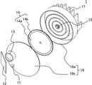
次に、図1乃至図4を参照して、光源装置1の構成について説明する。図1は、光源装置1の分解斜視図である。図2は、ケース16aの平面図である。図3は、光源装置1の断面図である。図4は、蛍光体ホイール14の回転により生じる空気の流れの説明図である。
(Structure of light source unit)
Next, the configuration of the
11は光源(固体光源)であり、後述の蛍光体層14bへ光を照射する。12は、光源11から射出された光を反射し、後述するように波長変換された光を透過するダイクロイックミラーである。13は集光光学系である。14は蛍光体ホイールであり、円板14aと、円板14aの上に円環状に塗布された蛍光体層14bとを含む。蛍光体層14bは、円板14aに設けられ、光源11からの光(入射光)の波長を変換する波長変換部材である。15は、蛍光体ホイール14を回転駆動するモータである。モータ15の回転軸は、蛍光体ホイール14の中心と同一となるように固定されている。16はケーシングであり、蛍光体ホイール14を包含するケース16aとカバー16bとを備えて構成される。本実施例において、ケーシング16(ケース16a、カバー16b)と集光光学系13とにより、円板14aを収納する収納部材を構成する。
光源11は、励起光(レーザ光)を射出する複数の半導体レーザダイオードを配列して構成されている。ただし、光源11の構成はこれに限定されるものではなく、例えば複数のLEDを配列して構成されていてもよい。光源11から射出した光は、集光光学系13を介して蛍光体層14bに集光する。
The
蛍光体ホイール14の円板14aは、アルミニウムや銅などの熱伝導率の高い材料からなり、円板14aの回転中心において蛍光体ホイール14を回転させるモータ15と連結される。また円板14aは、モータ15の回転軸を中心として回転可能に保持されている。すなわち蛍光体ホイール14の中心とモータ15の回転軸(回転中心)とを同一にすることにより、モータ15は、蛍光体ホイール14の中心を軸として回転することが可能となる。モータ15は、ケース16aにより保持されている。
The
このような構成により、光源11から射出された光は、蛍光体層14bに集光され、その一部の光が蛍光体に吸収される。光を吸収した蛍光体は励起されて蛍光光を発する波長変換部材として機能する。その結果、蛍光体層14bの微小領域に光エネルギーが集中し、蛍光体層14bは高温となる。そこで、蛍光体層14bが塗布される円板14aとして熱伝導率の高い部材を用いることにより、蛍光体層14bの熱を円板14aに放熱し、蛍光体層14bの温度を低下させる。また前述のように蛍光体ホイール14をモータ15で回転駆動することにより、光の照射領域が蛍光体層14bの上で常に移動するように構成し、蛍光体層14bの局所的な温度上昇(高温)を防止(抑制)する。また、蛍光体ホイール14が回転することにより、蛍光体層14bの表面と接する空気に流れを与え、更なる冷却効果を得ることができる。
With such a configuration, the light emitted from the
本実施例では、図3に示されるように、蛍光体ホイール14を包含するようにケース16aとカバー16bとを備えたケーシング16を設け、外部の空気から遮断した密閉空間Aを形成する。その結果、外部からの異物侵入による蛍光体層14bへの異物付着を防止することができる。一方、蛍光体層14bを冷却するには、密閉空間Aの内部の熱を、ケーシング16を介して外部へ放熱する必要がある。
In this embodiment, as shown in FIG. 3, a
蛍光体ホイール14が回転すると、図4に示されるように、蛍光体ホイール14と接する空気は、回転による遠心力で全周方向へ送風される(矢印W1)。また、その作用によって蛍光体ホイール14の表裏では負圧となり、その周囲の空気は蛍光体ホイール14側へ吸い寄せられるように移動するような空気の流れ(矢印W2)が生じる。
When the
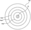
そこで本実施例では、図1乃至図3に示されるように、ケース16aの内面に、モータ15の回転軸(蛍光体ホイール14の回転中心)を中心とする円周状(円環状)の壁部16aF(凸部、ケース16a内のフィン)が複数設けられている。本実施例において、複数の壁部16aFはそれぞれ、モータ15の回転軸の周りに360度にわたって(全周にわたって)設けられている。複数の壁部16aFは、密閉空間Aの内部の熱をケーシング16に伝熱させるため、密閉空間Aの内部の空気との接触面積を増やすフィンとして機能する。したがって、密閉空間Aの内部の熱の伝達を促進するため、壁部16aFは、蛍光体ホイール14の近傍に配置(近接配置)することが好ましい。
Therefore, in this embodiment, as shown in FIGS. 1 to 3, a circumferential (annular) wall centered on the rotation axis of the motor 15 (rotation center of the phosphor wheel 14) is formed on the inner surface of the
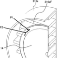
ここで、図9および図10を参照して、比較例としての光源装置10について説明する。図9は、比較例としての光源装置10の分解斜視図である。図10は、比較例としての光源装置10の要部の拡大図である。図9および図10に示されるように、光源装置10のケーシング216(ケース216a)には、直線状のフィン216aFが設けられている。このような直線状のフィン216aFを設けると、蛍光体ホイール14の回転に伴い、時間的な圧力変動が発生する。すなわち、図10に示されるように、回転する蛍光体ホイール14のある任意の点が壁部16aF1の先端近傍の位置(P1)を通過する際には圧力が上昇する一方、隣接する壁部16aF1の間の位置(P2)を通過する際には圧力が戻る(低下する)。このような現象は、蛍光体ホイール14の回転周期に起因する騒音の発生要因となる。
Here, the
そこで本実施例では、図1および図2に示されるように、ケース16aの内面に、モータ15の回転軸(蛍光体ホイール14の回転中心)を中心とする円周状の壁部16aFを複数形成する。このような構成により、蛍光体ホイール14の周囲の熱をケーシング16に効果的に伝熱することができる。また、このような構成により、蛍光体ホイール14の表面における圧力変動を低減することができ、蛍光体ホイール14の回転に起因する騒音の発生を低減することが可能となる。
Therefore, in this embodiment, as shown in FIGS. 1 and 2, a plurality of circumferential wall portions 16aF centered on the rotation axis of the motor 15 (rotation center of the phosphor wheel 14) are provided on the inner surface of the
なお本実施例のケース16aは、モータ15の回転軸(蛍光体ホイール14の回転中心)を中心とする円周状(円環状)の壁部16aF(凸部)が複数設けられているが、本実施例はこれに限定されるものではない。図5は、本実施例の変形例としてのケース116aの平面図である。ケース16aに代えて、図5に示されるように、モータ15の回転軸(蛍光体ホイール14の回転中心)を基準とする渦巻状の壁部116aF(凸部、ケース116a内のフィン)が設けられたケース116aを用いても、本実施例の効果を得ることができる。なお、「モータ15の回転軸を基準とする」とは、例えば、渦巻状の壁部116aFの開始位置を延長した場合にモータ15の回転軸を通過する構成をいう。
Although the
ここで渦巻状とは中心(モータ15の回転軸)から遠ざかるように旋回する2次元の曲線に沿った形状のことをいう。一方、渦巻状とは中心(モータ15の回転軸)から遠ざかるように旋回するとともに、旋回している面(図5の紙面)に対して垂直な方向にも動く3次元の曲線に沿った形状のことをいう。壁部16aFがr=a+bθの極座標形式の関数で表される、いわゆるアルキメデスの渦巻に沿った形状の場合や、r=a*b^θで表される、いわゆる対数渦巻に沿った形状の場合は、θ=0の位置とモータ15の回転軸が一致しているといえる。好ましくは、壁部16aF(または壁部116aF)を熱伝導率の高い金属で構成する。このような構成によれば、密閉空間Aの内部の熱をケーシング16に対してより効果的に伝熱することができ、蛍光体層14bの温度をより低減することが可能となる。
Here, the spiral shape means a shape along a two-dimensional curve that swirls away from the center (rotational axis of the motor 15). On the other hand, the spiral shape is a shape along a three-dimensional curve that swivels away from the center (rotational axis of the motor 15) and also moves in a direction perpendicular to the swirling surface (paper surface in FIG. 5). It means that. When the wall portion 16aF is represented by a function in the polar coordinate format of r = a + bθ, that is, a shape along a so-called Archimedes spiral, or when it is represented by r = a * b ^ θ, a shape along a so-called logarithmic spiral. Can be said that the position of θ = 0 and the rotation axis of the
好ましくは、図1および図3に示されるように、ケーシング16(カバー16a)の外面に放熱用のフィン17を設ける。このような構成によれば、ケーシング16の放熱面積が増大するため、ケーシング16から外部への放熱効率をより高めることができ、蛍光体層14bの温度をより低減することが可能となる。より好ましくは、ケーシング16の外面のフィンFの周囲の空気を流動させる冷却ファン(不図示)を設ける。これにより、冷却効率をより高めることができる。
Preferably, as shown in FIGS. 1 and 3,
なお本実施例は、光源11から射出された光を反射させる構成について説明したが、これに限定されるものではない。本実施例は、例えば、円板14aとして光透過部材(ガラス、水晶、サファイアなど)を用いて、光源11から射出した光を透過させる構成にも適用可能である。
In this embodiment, the configuration for reflecting the light emitted from the
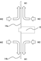
次に、図6および図7を参照して、本発明の実施例2における光源装置1aについて説明する。図6は、光源装置1aの分解斜視図である。図7は、光源装置1aのケースの平面図である。 Next, the light source device 1a according to the second embodiment of the present invention will be described with reference to FIGS. 6 and 7. FIG. 6 is an exploded perspective view of the light source device 1a. FIG. 7 is a plan view of the case of the light source device 1a.
実施例1では、モータ15の回転軸の全周にわたって設けられた円周状の壁部16aF(または渦巻状の壁部116aF)について説明したが、図4を参照して説明したように、回転する蛍光体ホイール14は、周方向に放射状に空気の流れを構築する特性がある。そこで本実施例では、図6および図7に示されるように、壁部16aFに回転中心から放射状にスリット16s(隙間)を設ける。このような構成により、蛍光体ホイール14が回転することで発生する気流(図7中の矢印W1)が壁部16aFの周囲を流れることを妨げず、ケーシング16(密閉空間A)の内部における空気の循環を盛んにすることが可能となる。
In the first embodiment, the circumferential wall portion 16aF (or the spiral wall portion 116aF) provided over the entire circumference of the rotation shaft of the
このように本実施例において、複数の壁部116aFはそれぞれ、モータ15の回転軸の周りの一部の位相(位置)において隙間(スリット16s)が設けられている。好ましくは、複数の壁部116aFはそれぞれ、一部の位相として、モータ15の回転軸から放射方向に沿った所定の位相においてスリット16sが設けられている。ただし、複数の壁部116aFに設けられるスリット16sの位相は、互いに異なっていてもよい。また、複数の壁部116aFの全てにスリット16sを設ける必要はなく、複数の壁部116aFの少なくとも一つに関してスリット16sを設けてもよい。
As described above, in the present embodiment, each of the plurality of wall portions 116aF is provided with a gap (slit 16s) in a part of the phase (position) around the rotation axis of the
このような構成により、蛍光体ホイール14のある任意の点における圧力変動の発生を防止し、騒音の発生を抑制しつつ、蛍光体層14bの熱をケーシング16に効果的に伝達(放熱)することができる。なお、凸形状が円環状ではなく渦巻状に形成された構成された場合でも、スリットによる同様の効果が得られる。
With such a configuration, the heat of the
各実施例によれば、蛍光体ホイールを回転させるためのモータの負荷の増大を抑制しつつ、蛍光体ホイールによる発熱をケーシングの外部へ効率的に放熱することが可能な光源装置および投射型表示装置を提供することができる。 According to each embodiment, a light source device and a projection type display capable of efficiently dissipating heat generated by the phosphor wheel to the outside of the casing while suppressing an increase in the load of the motor for rotating the phosphor wheel. The device can be provided.
以上、本発明の好ましい実施例について説明したが、本発明はこれらの実施例に限定されず、その要旨の範囲内で種々の変形及び変更が可能である。 Although the preferred embodiments of the present invention have been described above, the present invention is not limited to these examples, and various modifications and modifications can be made within the scope of the gist thereof.
1、1a 光源装置
11 光源
13 集光光学系
14a 円板
14b 蛍光体層(波長変換部材)
16 ケーシング
16aF、116aF 壁部
1, 1a
16 Casing 16aF, 116aF Wall
Claims (6)
回転軸を中心として回転可能に保持された円板と、
前記円板に設けられた、前記光源からの光の波長を変換する波長変換部材と、
前記円板を収納する収納部材を有し、
前記収納部材は、該収納部材の内部に、前記回転軸を中心とする同心円状の複数の円筒面からなる壁部を備え、前記円筒面はそれぞれ複数のスリットを有することを特徴とする光源装置。 Light source and
A disk held rotatably around the axis of rotation,
A wavelength conversion member provided on the disk that converts the wavelength of light from the light source, and
It has a storage member for storing the disk, and has a storage member.
The housing member, the interior of the housing member, the rotary shaft comprises a wall portion consisting of a plurality of concentric cylindrical surface centered on the light source device which comprises said cylindrical surface a plurality of slits ..
前記光源装置から射出された光を変調して投射する光学系を保持可能な筺体を有することを特徴とする投射型表示装置。 The light source device according to any one of claims 1 to 5.
A projection-type display device having a housing capable of holding an optical system that modulates and projects light emitted from the light source device.
Priority Applications (2)
| Application Number | Priority Date | Filing Date | Title |
|---|---|---|---|
| JP2016247786A JP6987499B2 (en) | 2016-12-21 | 2016-12-21 | Light source device and projection type display device |
| US15/847,664 US10401719B2 (en) | 2016-12-21 | 2017-12-19 | Light source apparatus and projection-type display apparatus |
Applications Claiming Priority (1)
| Application Number | Priority Date | Filing Date | Title |
|---|---|---|---|
| JP2016247786A JP6987499B2 (en) | 2016-12-21 | 2016-12-21 | Light source device and projection type display device |
Publications (3)
| Publication Number | Publication Date |
|---|---|
| JP2018101089A JP2018101089A (en) | 2018-06-28 |
| JP2018101089A5 JP2018101089A5 (en) | 2019-04-04 |
| JP6987499B2 true JP6987499B2 (en) | 2022-01-05 |
Family
ID=62561531
Family Applications (1)
| Application Number | Title | Priority Date | Filing Date |
|---|---|---|---|
| JP2016247786A Active JP6987499B2 (en) | 2016-12-21 | 2016-12-21 | Light source device and projection type display device |
Country Status (2)
| Country | Link |
|---|---|
| US (1) | US10401719B2 (en) |
| JP (1) | JP6987499B2 (en) |
Families Citing this family (5)
| Publication number | Priority date | Publication date | Assignee | Title |
|---|---|---|---|---|
| JP7003935B2 (en) * | 2016-12-19 | 2022-01-21 | ソニーグループ株式会社 | Light source device and projection type display device |
| CN111344632B (en) * | 2018-02-02 | 2021-12-03 | 麦克赛尔株式会社 | Light source device, projector, and lighting device |
| JP2020042236A (en) * | 2018-09-13 | 2020-03-19 | パナソニックIpマネジメント株式会社 | Phosphor wheel device, illumination device, and projection-type image display apparatus |
| CN111999970A (en) * | 2019-05-27 | 2020-11-27 | 中强光电股份有限公司 | Wavelength conversion module, light source device and projection equipment |
| JP2023005566A (en) * | 2021-06-29 | 2023-01-18 | セイコーエプソン株式会社 | Light source device and projector |
Family Cites Families (15)
| Publication number | Priority date | Publication date | Assignee | Title |
|---|---|---|---|---|
| JPH10154889A (en) | 1996-11-25 | 1998-06-09 | Yaskawa Electric Corp | Cooling device |
| JP3724326B2 (en) * | 2000-04-10 | 2005-12-07 | 株式会社日立製作所 | Display device |
| KR20080029514A (en) * | 2006-09-29 | 2008-04-03 | 삼성전자주식회사 | A projection type display appartus |
| JP5429079B2 (en) * | 2010-06-30 | 2014-02-26 | 株式会社Jvcケンウッド | Light source device and projection display device |
| JP6225338B2 (en) * | 2012-11-07 | 2017-11-08 | パナソニックIpマネジメント株式会社 | Light source and image projection device |
| JP6264117B2 (en) | 2014-03-18 | 2018-01-24 | 日本電気株式会社 | COOLING DEVICE, ELECTRONIC DEVICE, AND COOLING METHOD |
| JP5804130B2 (en) | 2014-04-16 | 2015-11-04 | セイコーエプソン株式会社 | Light source device and projector |
| JP6617274B2 (en) * | 2014-09-17 | 2019-12-11 | パナソニックIpマネジメント株式会社 | Phosphor wheel device, phosphor wheel device housing, and projection-type image display device |
| JP6428193B2 (en) * | 2014-11-21 | 2018-11-28 | 日亜化学工業株式会社 | Wavelength conversion member and projector provided with the wavelength conversion member |
| TWI576650B (en) * | 2014-12-08 | 2017-04-01 | 台達電子工業股份有限公司 | Color wheel device |
| JP2016153873A (en) * | 2015-02-17 | 2016-08-25 | セイコーエプソン株式会社 | Wavelength conversion device, illumination device and projector |
| WO2016147226A1 (en) * | 2015-03-19 | 2016-09-22 | パナソニックIpマネジメント株式会社 | Housing, phosphor wheel device, and projection device |
| JP6281131B2 (en) * | 2015-12-10 | 2018-02-21 | パナソニックIpマネジメント株式会社 | Light conversion device and projection display device having the same |
| CN107203088B (en) * | 2016-03-18 | 2019-10-22 | 中强光电股份有限公司 | Wavelength transformational structure and projection arrangement |
| JP7003935B2 (en) * | 2016-12-19 | 2022-01-21 | ソニーグループ株式会社 | Light source device and projection type display device |
-
2016
- 2016-12-21 JP JP2016247786A patent/JP6987499B2/en active Active
-
2017
- 2017-12-19 US US15/847,664 patent/US10401719B2/en active Active
Also Published As
| Publication number | Publication date |
|---|---|
| US10401719B2 (en) | 2019-09-03 |
| JP2018101089A (en) | 2018-06-28 |
| US20180173086A1 (en) | 2018-06-21 |
Similar Documents
| Publication | Publication Date | Title |
|---|---|---|
| JP6987499B2 (en) | Light source device and projection type display device | |
| JP6924923B2 (en) | Fluorescent wheel device, lighting device, and projection type image display device | |
| US20200332993A1 (en) | Cooling of a converter arrangement for light sources with high luminance | |
| JP6617274B2 (en) | Phosphor wheel device, phosphor wheel device housing, and projection-type image display device | |
| JP6979572B2 (en) | Phosphor wheel and phosphor wheel device equipped with it, light conversion device, projection type display device | |
| US10527840B2 (en) | Light conversion device and projection display apparatus including same | |
| EP2871519A2 (en) | Light source apparatus and image projection apparatus | |
| JP6890244B2 (en) | Cooling device and projection type image display device | |
| JP6402893B2 (en) | Optical wheel device and projection device | |
| US10520800B2 (en) | Phosphor wheel, phosphor wheel device including the same, light conversion device, and projection display apparatus | |
| JP6015138B2 (en) | Image projection device | |
| WO2017154048A1 (en) | Phosphor wheel and projection image display device | |
| JP2008052176A (en) | Color wheel unit | |
| JP6846601B2 (en) | Fluorescent wheel device, light conversion device equipped with this, projection type display device | |
| WO2016185851A1 (en) | Light conversion device, light source device, and projector | |
| JP5700494B2 (en) | Projection device | |
| JP7030473B2 (en) | A light source device and a projection type display device having this | |
| JP7113333B2 (en) | WAVELENGTH CONVERSION WHEEL DEVICE, LIGHTING DEVICE, AND PROJECTION TYPE VIDEO DISPLAY DEVICE | |
| JP2018022000A (en) | Heat radiation structure, and projection-type image display device | |
| JP6890248B2 (en) | Cooling device and projection type image display device | |
| JP2023070969A (en) | Light source device and image projection device | |
| WO2022163218A1 (en) | Fluorescent wheel | |
| JP2020166201A (en) | Phosphor unit and projection type display device | |
| JP2020173371A (en) | Projection type image display device |
Legal Events
| Date | Code | Title | Description |
|---|---|---|---|
| A521 | Written amendment |
Free format text: JAPANESE INTERMEDIATE CODE: A523 Effective date: 20190208 |
|
| A621 | Written request for application examination |
Free format text: JAPANESE INTERMEDIATE CODE: A621 Effective date: 20190208 |
|
| A977 | Report on retrieval |
Free format text: JAPANESE INTERMEDIATE CODE: A971007 Effective date: 20191113 |
|
| A131 | Notification of reasons for refusal |
Free format text: JAPANESE INTERMEDIATE CODE: A131 Effective date: 20191217 |
|
| A521 | Written amendment |
Free format text: JAPANESE INTERMEDIATE CODE: A523 Effective date: 20200214 |
|
| A131 | Notification of reasons for refusal |
Free format text: JAPANESE INTERMEDIATE CODE: A131 Effective date: 20200303 |
|
| A601 | Written request for extension of time |
Free format text: JAPANESE INTERMEDIATE CODE: A601 Effective date: 20200430 |
|
| A521 | Written amendment |
Free format text: JAPANESE INTERMEDIATE CODE: A523 Effective date: 20200629 |
|
| A02 | Decision of refusal |
Free format text: JAPANESE INTERMEDIATE CODE: A02 Effective date: 20201124 |
|
| A521 | Written amendment |
Free format text: JAPANESE INTERMEDIATE CODE: A523 Effective date: 20210222 |
|
| C60 | Trial request (containing other claim documents, opposition documents) |
Free format text: JAPANESE INTERMEDIATE CODE: C60 Effective date: 20210222 |
|
| A911 | Transfer to examiner for re-examination before appeal (zenchi) |
Free format text: JAPANESE INTERMEDIATE CODE: A911 Effective date: 20210303 |
|
| C21 | Notice of transfer of a case for reconsideration by examiners before appeal proceedings |
Free format text: JAPANESE INTERMEDIATE CODE: C21 Effective date: 20210309 |
|
| A912 | Re-examination (zenchi) completed and case transferred to appeal board |
Free format text: JAPANESE INTERMEDIATE CODE: A912 Effective date: 20210514 |
|
| C211 | Notice of termination of reconsideration by examiners before appeal proceedings |
Free format text: JAPANESE INTERMEDIATE CODE: C211 Effective date: 20210518 |
|
| C22 | Notice of designation (change) of administrative judge |
Free format text: JAPANESE INTERMEDIATE CODE: C22 Effective date: 20210706 |
|
| C13 | Notice of reasons for refusal |
Free format text: JAPANESE INTERMEDIATE CODE: C13 Effective date: 20210824 |
|
| A521 | Written amendment |
Free format text: JAPANESE INTERMEDIATE CODE: A523 Effective date: 20210917 |
|
| C302 | Record of communication |
Free format text: JAPANESE INTERMEDIATE CODE: C302 Effective date: 20210930 |
|
| C23 | Notice of termination of proceedings |
Free format text: JAPANESE INTERMEDIATE CODE: C23 Effective date: 20211005 |
|
| C03 | Trial/appeal decision taken |
Free format text: JAPANESE INTERMEDIATE CODE: C03 Effective date: 20211102 |
|
| C30A | Notification sent |
Free format text: JAPANESE INTERMEDIATE CODE: C3012 Effective date: 20211102 |
|
| A61 | First payment of annual fees (during grant procedure) |
Free format text: JAPANESE INTERMEDIATE CODE: A61 Effective date: 20211201 |
|
| R151 | Written notification of patent or utility model registration |
Ref document number: 6987499 Country of ref document: JP Free format text: JAPANESE INTERMEDIATE CODE: R151 |