JP6984529B2 - A base material for a vapor deposition mask, a method for manufacturing a base material for a vapor deposition mask, a method for manufacturing a vapor deposition mask, and a method for manufacturing a display device. - Google Patents
A base material for a vapor deposition mask, a method for manufacturing a base material for a vapor deposition mask, a method for manufacturing a vapor deposition mask, and a method for manufacturing a display device. Download PDFInfo
- Publication number
- JP6984529B2 JP6984529B2 JP2018072336A JP2018072336A JP6984529B2 JP 6984529 B2 JP6984529 B2 JP 6984529B2 JP 2018072336 A JP2018072336 A JP 2018072336A JP 2018072336 A JP2018072336 A JP 2018072336A JP 6984529 B2 JP6984529 B2 JP 6984529B2
- Authority
- JP
- Japan
- Prior art keywords
- metal plate
- mask
- steepness
- vapor deposition
- width direction
- Prior art date
- Legal status (The legal status is an assumption and is not a legal conclusion. Google has not performed a legal analysis and makes no representation as to the accuracy of the status listed.)
- Active
Links
Images


Description
本発明は、蒸着マスク用基材、蒸着マスク用基材の製造方法、蒸着マスクの製造方法および表示装置の製造方法に関する。 The present invention relates to a base material for a vapor deposition mask, a method for manufacturing a base material for a vapor deposition mask, a method for manufacturing a vapor deposition mask, and a method for manufacturing a display device.
蒸着マスクは、第1面と第2面とを備える。第1面は、基板などの対象物と対向し、第2面は、第1面とは反対側に位置する。第1面から第2面までを貫通する孔は、第1面に位置する第1開口と、第2面に位置する第2開口とを備える。第2開口から孔に入る蒸着物質は、第1開口の位置や第1開口の形状に追従したパターンを対象物に形成する(例えば、特許文献1を参照)。 The vapor deposition mask includes a first surface and a second surface. The first surface faces an object such as a substrate, and the second surface is located on the opposite side to the first surface. The hole penetrating from the first surface to the second surface includes a first opening located on the first surface and a second opening located on the second surface. The vapor-filmed substance that enters the hole from the second opening forms a pattern that follows the position of the first opening and the shape of the first opening on the object (see, for example, Patent Document 1).
蒸着マスクが備える孔は、第1開口から第2開口に向けて拡大する断面積を有し、それによって、第2開口から孔に入る蒸着物質の数量を高めて、第1開口に到達する蒸着物質の数量を確保する。一方、第2開口から孔に入る蒸着物質の一部は、第1開口に到達せずに、孔を区画する壁面に少なからず付着する。壁面に付着した蒸着物質は、他の蒸着物質による孔の通過を妨げて、パターンが有する寸法の精度を低下させる。 The holes provided in the vapor deposition mask have a cross-sectional area that expands from the first opening to the second opening, thereby increasing the amount of vapor deposition material entering the holes through the second opening and reaching the first opening. Secure the quantity of substances. On the other hand, a part of the vapor-filmed substance that enters the hole from the second opening does not reach the first opening and adheres to the wall surface that partitions the hole. The vapor-deposited material adhering to the wall surface prevents the passage of holes by other thin-film-deposited materials and reduces the accuracy of the dimensions of the pattern.
近年では、壁面に付着する蒸着物質の体積を低下させることを目的として、蒸着マスクの厚みを薄くし、壁面の面積そのものを縮小させることが検討されている。そして、蒸着マスクの厚みを薄くする技術として、蒸着マスクを製造するための基材である金属板の厚みそのものを薄くすることが検討されている。 In recent years, it has been studied to reduce the thickness of the vapor deposition mask and reduce the area of the wall surface itself for the purpose of reducing the volume of the vapor deposition substance adhering to the wall surface. Then, as a technique for reducing the thickness of the vapor deposition mask, it is considered to reduce the thickness of the metal plate itself, which is a base material for manufacturing the vapor deposition mask.
他方、金属板に孔を形成するエッチングの工程では、金属板の厚みが薄くなるほど、除去される金属の体積が小さくなる。そのため、金属板にエッチング液を供給する時間や、供給されるエッチングの温度などの加工条件で許容範囲が狭くなり、結果として、第1開口や第2開口の寸法に十分な精度を得られがたくなっている。特に、金属板を製造する技術では、ローラーによって母材を延ばす圧延や、電極に析出した金属板を電極から剥がす電解が用いられ、金属板そのものに波形状が形成されている。こうした形状を有する金属板は、金属板とエッチング液との接触する時間を、例えば、波形状の山部と波形状の谷部との間で大きく異ならせて、上記許容範囲の狭小化に伴う精度の低下をさらに深刻化させている。以上のように、蒸着マスクの厚みを薄くする技術は、壁面に付着する蒸着物質の量を低下させて、それによって、蒸着の繰り返しでのパターンの寸法の精度を高められるが、蒸着ごとでは、パターンの寸法に必要な精度を得られがたい課題を新たに招来させている。 On the other hand, in the etching process of forming holes in a metal plate, the thinner the metal plate, the smaller the volume of metal to be removed. Therefore, the permissible range is narrowed depending on the processing conditions such as the time for supplying the etching solution to the metal plate and the temperature of the etching to be supplied, and as a result, sufficient accuracy can be obtained for the dimensions of the first opening and the second opening. I want to. In particular, in the technique for manufacturing a metal plate, rolling in which the base metal is stretched by a roller and electrolysis in which the metal plate deposited on the electrode is peeled off from the electrode are used, and a wavy shape is formed on the metal plate itself. In the metal plate having such a shape, the contact time between the metal plate and the etching solution is greatly different, for example, between the wavy peaks and the wavy valleys, and the allowable range is narrowed. The decrease in accuracy is further exacerbated. As described above, the technique of reducing the thickness of the vapor deposition mask reduces the amount of vapor deposition material adhering to the wall surface, thereby improving the accuracy of the pattern dimensions in repeated vapor deposition. It introduces a new problem that it is difficult to obtain the accuracy required for pattern dimensions.
本発明の目的は、蒸着によって形成されるパターンの精度を向上可能とした蒸着マスク用基材、蒸着マスク用基材の製造方法、蒸着マスクの製造方法および表示装置の製造方法を提供することである。 An object of the present invention is to provide a base material for a vapor deposition mask, a method for manufacturing a base material for a vapor deposition mask, a method for manufacturing a vapor deposition mask, and a method for manufacturing a display device, which can improve the accuracy of a pattern formed by vapor deposition. be.
上記課題を解決するための蒸着マスク用基材は、複数の孔がエッチングによって形成されて蒸着マスクの製造に用いられる、帯状を有した金属板である蒸着マスク用基材であって、前記金属板の幅方向での各位置における前記金属板の長手方向に沿った形状は、相互に異なっており、各形状は、前記金属板の長手方向に繰り返す波を有し、前記波における一方の谷から他方の谷までを結ぶ直線の長さが波の長さであり、前記波の長さに対する前記波の高さの百分率が単位急峻度であり、前記金属板の幅方向の各位置において、前記長手方向に含まれる全ての波での単位急峻度の平均値が急峻度であり、前記金属板の幅方向での中央部における急峻度の最大値が、0.3%以下であり、前記金属板の幅方向での各端部における急峻度の最大値が、0.6%以下であり、前記金属板の幅方向での両端部のなかの少なくとも一方での急峻度の最大値は、前記金属板の幅方向の中央部における急峻度の最大値よりも小さい。 The base material for a vapor deposition mask for solving the above-mentioned problems is a base material for a vapor deposition mask, which is a metal plate having a strip shape in which a plurality of holes are formed by etching and is used for manufacturing the vapor deposition mask. The shapes along the longitudinal direction of the metal plate at each position in the width direction of the plate are different from each other, and each shape has a wave repeating in the longitudinal direction of the metal plate, and one valley in the wave. The length of the straight line connecting from to the other valley is the length of the wave, the percentage of the height of the wave to the length of the wave is the unit steepness, and at each position in the width direction of the metal plate. The average value of the unit steepness in all the waves included in the longitudinal direction is the steepness, and the maximum value of the steepness in the central portion in the width direction of the metal plate is 0.3% or less. The maximum value of steepness at each end of the metal plate in the width direction is 0.6% or less, and the maximum value of steepness of at least one of both ends of the metal plate in the width direction is It is smaller than the maximum value of steepness in the central portion in the width direction of the metal plate.
上記課題を解決するための蒸着マスク用基材の製造方法は、複数の孔がエッチングによって形成されて蒸着マスクの製造に用いられる、帯状を有した金属板である蒸着マスク用基材の製造方法であって、母材を圧延して前記金属板を得ることを含み、前記金属板の幅方向での各位置における前記金属板の長手方向に沿った形状は、相互に異なっており、各形状は、前記金属板の長手方向に繰り返す波を有し、前記波における一方の谷から他方の谷までを結ぶ直線の長さが波の長さであり、前記波の長さに対する前記波の高さの百分率が単位急峻度であり、前記金属板の幅方向の各位置において、前記長手方向に含まれる全ての波での単位急峻度の平均値が急峻度であり、前記金属板を得ることでは、前記金属板の幅方向での中央部における急峻度の最大値が、0.3%以下であり、前記金属板の幅方向での各端部における急峻度の最大値が、0.6%以下であり、前記金属板の幅方向での両端部のなかの少なくとも一方での急峻度の最大値は、前記金属板の幅方向の中央部における急峻度の最大値よりも小さくなるように、前記母材を圧延する。 A method for manufacturing a base material for a vapor deposition mask for solving the above problems is a method for manufacturing a base material for a vapor deposition mask, which is a strip-shaped metal plate used for manufacturing a vapor deposition mask in which a plurality of holes are formed by etching. Including rolling the base metal to obtain the metal plate, the shapes along the longitudinal direction of the metal plate at each position in the width direction of the metal plate are different from each other, and each shape. Has waves that repeat in the longitudinal direction of the metal plate, the length of a straight line connecting one valley to the other in the wave is the length of the wave, and the height of the wave with respect to the length of the wave. The percentage of the unit steepness is the unit steepness, and the average value of the unit steepness in all the waves included in the longitudinal direction at each position in the width direction of the metal plate is the steepness, and the metal plate is obtained. Then, the maximum value of the steepness at the central portion in the width direction of the metal plate is 0.3% or less, and the maximum value of the steepness at each end portion in the width direction of the metal plate is 0.6. % Or less, so that the maximum value of the steepness of at least one of both ends of the metal plate in the width direction is smaller than the maximum value of the steepness in the central portion of the metal plate in the width direction. , The base metal is rolled.
上記課題を解決するための蒸着マスクの製造方法は、帯状を有した金属板にレジスト層を形成することと、前記レジスト層をマスクとしたエッチングによって前記金属板に複数の孔を形成してマスク部を形成することと、を含む蒸着マスクの製造方法であって、前記金属板の幅方向での各位置における前記金属板の長手方向に沿った形状は、相互に異なっており、各形状は、前記金属板の長手方向に繰り返す波を有し、前記波における一方の谷から他方の谷までを結ぶ直線の長さが波の長さであり、前記波の長さに対する前記波の高さの百分率が単位急峻度であり、前記金属板の幅方向の各位置において、前記長手方向に含まれる全ての波での単位急峻度の平均値が急峻度であり、前記金属板の幅方向での中央部における急峻度の最大値が、0.3%以下であり、前記金属板の幅方向での各端部における急峻度の最大値が、0.6%以下であり、前記金属板の幅方向での両端部のなかの少なくとも一方での急峻度の最大値は、前記金属板の幅方向の中央部における急峻度の最大値よりも小さい。 A method for manufacturing a vapor deposition mask for solving the above problems is to form a resist layer on a metal plate having a band shape and to form a plurality of holes in the metal plate by etching using the resist layer as a mask to form a mask. It is a method of manufacturing a vapor deposition mask including forming a portion, and the shapes along the longitudinal direction of the metal plate at each position in the width direction of the metal plate are different from each other, and each shape is different. , The length of a straight line connecting one valley to the other in the wave having a wave repeating in the longitudinal direction of the metal plate is the length of the wave, and the height of the wave with respect to the length of the wave. The percentage of the unit steepness is the unit steepness, and the average value of the unit steepness in all the waves included in the longitudinal direction at each position in the width direction of the metal plate is the steepness, and in the width direction of the metal plate. The maximum value of steepness in the central portion of the metal plate is 0.3% or less, and the maximum value of steepness at each end of the metal plate in the width direction is 0.6% or less. The maximum value of the steepness of at least one of both ends in the width direction is smaller than the maximum value of the steepness in the central portion in the width direction of the metal plate.
上記蒸着マスク用基材によれば、少なくとも一方の端部での急峻度の最大値が、中央部での急峻度の最大値よりも小さいため、中央部の表面での波の起伏が、少なくとも一方の端部よりも激しくなる。結果として、蒸着マスク用基材の表面に供給される液体を、中央部から少なくとも一方の端部へ、さらには、少なくとも一方の端部から蒸着マスク用基材の外側へ流しやすい。結果として、蒸着マスク用基材の表面に供給された液体の流れに淀みを生じ難く、エッチングおける液体による処理を用いた加工の均一性、すなわち、蒸着マスク用基材が有する孔の均一性、ひいては、蒸着によって形成されるパターンの精度を向上することが可能となる。 According to the above-mentioned substrate for vapor deposition mask, the maximum value of the steepness at at least one end is smaller than the maximum value of the steepness at the central portion, so that the undulation of the wave on the surface of the central portion is at least. It is more intense than one end. As a result, the liquid supplied to the surface of the film-deposited mask substrate is likely to flow from the central portion to at least one end, and further from at least one end to the outside of the film-deposited mask substrate. As a result, the flow of the liquid supplied to the surface of the substrate for the vapor deposition mask is less likely to stagnate, and the uniformity of processing using the treatment with the liquid in the etching, that is, the uniformity of the holes of the substrate for the vapor deposition mask, As a result, it is possible to improve the accuracy of the pattern formed by the vapor deposition.
上記蒸着マスク用基材において、一方の前記端部での急峻度の最大値は、前記中央部での急峻度の最大値よりも小さく、他方の前記端部での急峻度の最大値は、前記中央部での急峻度の最大値よりも大きく、一方の前記端部での急峻度の最大値と、他方の前記端部での急峻度の最大値との差は、0.2%以上0.4%以下であってもよい。この蒸着マスク用基材によれば、一方の端部の表面での波の起伏が、中央部よりも緩やかであり、かつ、他方の端部の表面での波の起伏が、0.6%以下の急峻度を有しながらも、中央部よりも激しい。こうした蒸着マスク用基材は、蒸着マスク用基材の表面に供給される液体を、他方の端部から一方の端部へ、さらに、一方の端部から蒸着マスク用基材の外側へ流しやすい。 In the thin-film mask substrate, the maximum value of steepness at one end is smaller than the maximum value of steepness at the center, and the maximum value of steepness at the other end is It is larger than the maximum value of steepness at the central portion, and the difference between the maximum value of steepness at one end and the maximum value of steepness at the other end is 0.2% or more. It may be 0.4% or less. According to this vapor deposition mask substrate, the wave undulations on the surface of one end are gentler than those in the center, and the wave undulations on the surface of the other end are 0.6%. Although it has the following steepness, it is more intense than the central part. In such a thin-film deposition mask base material, the liquid supplied to the surface of the thin-film deposition mask base material can easily flow from the other end to one end and further from one end to the outside of the thin-film deposition mask base material. ..
上記蒸着マスク用基材において、一方の前記端部での急峻度の最大値および他方の前記端部での急峻度の最大値は、前記中央部での急峻度の最大値よりも小さく、前記両端部での急峻度の最大値および前記中央部での急峻度の最大値は、0.2%以下であってもよい。この蒸着マスク用基材によれば、中央部の表面での波の起伏が、0.3%以下の急峻度を有しながらも、各端部よりも激しいため、蒸着マスク用基材の表面に供給される液体を、中央部から各端部へ、さらに、各端部から蒸着マスク用基材1の外側へ流しやすい。
In the thin-film deposition mask substrate, the maximum value of steepness at one end and the maximum value of steepness at the other end are smaller than the maximum value of steepness at the center, and the above-mentioned The maximum value of steepness at both ends and the maximum value of steepness at the center may be 0.2% or less. According to this thin-film deposition mask base material, the undulations of the waves on the surface of the central portion are steeper than 0.3% or less, but more severe than each end, so that the surface of the vapor-film mask base material The liquid supplied to the film can be easily flowed from the central portion to each end portion and further from each end portion to the outside of the thin-film deposition
上記蒸着マスクの製造方法において、前記マスク部を形成することは、単一の前記金属板に複数の前記マスク部を形成することであり、前記各マスク部が、前記複数の孔を有した1つの側面を別々に備え、前記各マスク部の側面と、1体のフレーム部とを、前記複数の孔を前記マスク部ごとに前記1体のフレーム部が囲うように、相互に接合することをさらに含むことも可能である。この蒸着マスクの製造方法によれば、各マスク部の側面と、1体のフレーム部とが接合されるため、複数のマスク部を備えた蒸着マスクにおいて、各マスク部における形状の安定性を高めることが可能ともなる。 In the method for manufacturing a vapor deposition mask, forming the mask portion means forming a plurality of the mask portions on a single metal plate, and each mask portion has the plurality of holes1. Two side surfaces are separately provided, and the side surface of each mask portion and one frame portion are joined to each other so that the plurality of holes are surrounded by the one frame portion for each mask portion. It can also be included further. According to this method for manufacturing a thin-film deposition mask, since the side surface of each mask portion and one frame portion are joined, the stability of the shape of each mask portion is improved in the vapor-filming mask provided with a plurality of mask portions. It will also be possible.
上記課題を解決するための表示装置の製造方法は、上記蒸着マスクの製造方法による蒸着マスクを準備することと、前記蒸着マスクを用いた蒸着によってパターンを形成することとを含む。 A method for manufacturing a display device for solving the above problems includes preparing a vapor deposition mask according to the method for manufacturing a vapor deposition mask and forming a pattern by vapor deposition using the vapor deposition mask.
上記各構成によれば、蒸着によって形成されるパターンの精度を向上できる。 According to each of the above configurations, the accuracy of the pattern formed by the vapor deposition can be improved.
図1から図29を参照して、蒸着マスク用基材、蒸着マスク用基材の製造方法、蒸着マスクの製造方法および表示装置の製造方法の一実施形態を説明する。
[蒸着マスク用基材の構成]
An embodiment of a base material for a vapor deposition mask, a method for manufacturing a base material for a vapor deposition mask, a method for manufacturing a vapor deposition mask, and a method for manufacturing a display device will be described with reference to FIGS. 1 to 29.
[Construction of base material for vapor deposition mask]
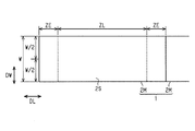
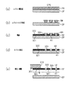
図1が示すように、蒸着マスク用基材1は、帯状を有した金属板である。蒸着マスク用基材1は、短手方向である幅方向DWの各位置で、長手方向DLに繰り返される波を有した波形状を有する。蒸着マスク用基材1の幅方向DWでの各位置は、相互に異なる波形状を有する。相互に異なる波形状では、波形状に含まれる波の数、波の長さ、波の高さなどが相互に異なる。なお、図1では、蒸着マスク用基材1が有する形状を説明するために、実際よりも波形状を誇張して示す。蒸着マスク用基材1の有する厚みは、15μm以上50μm以下である。蒸着マスク用基材1の有する厚みの均一性は、例えば、厚みの平均値に対する厚みの最大値と厚みの最小値との差分の比率が、5%以下である。
As shown in FIG. 1, the
蒸着マスク用基材1を構成する材料は、ニッケル、もしくは、鉄ニッケル合金であり、例えば、30質量%以上のニッケルを含む鉄ニッケル合金、なかでも、36質量%ニッケルと64質量%鉄との合金を主成分とする、すなわちインバーであることが好ましい。36質量%ニッケルと64質量%鉄との合金を主成分とする場合、残余分はクロム、マンガン、炭素、コバルトなどの添加物を含む。蒸着マスク用基材1を構成する材料が、インバーである場合、蒸着マスク用基材1の熱膨張係数は、例えば、1.2×10⁻⁶/℃程度である。このような熱膨張係数を有する蒸着マスク用基材1であれば、蒸着マスク用基材1から製造されるマスクでの熱膨張による大きさの変化と、ガラス基板やポリイミドシートでの熱膨張による大きさの変化とが同じ程度であるため、蒸着対象の一例として、ガラス基板やポリイミドシートを用いることが好適である。
The material constituting the
[急峻度]
蒸着マスク用基材1が水平面に載置された状態において、水平面に対する蒸着マスク用基材1の表面の位置(高さ)が表面位置である。
図2が示すように、表面位置の計測では、まず、蒸着マスク用基材1が幅方向DWの全体(全幅)において切断されるスリット工程が実施されて、蒸着マスク用基材1の長手方向DLにおける一部分として、測定用基材2Mが切り出される。測定用基材2Mの幅方向DWでの寸法Wは、蒸着マスク用基材1の幅方向DWでの寸法と等しい。次いで、測定用基材2Mの表面2Sについて、幅方向DWの所定の間隔ごとに、長手方向DLの各位置での表面位置が計測される。表面位置が計測される範囲は、計測範囲ZLである。計測範囲ZLは、測定用基材2Mの長手方向DLでの両方の端部である非計測範囲ZEを除く範囲である。蒸着マスク用基材1を切断するスリット工程は、蒸着マスク用基材1とは異なる新たな波形状を測定用基材に形成し得る。各非計測範囲ZEの長手方向DLでの長さは、こうした新たな波形状が形成され得る範囲であり、表面位置の測定からは除外される範囲である。各非計測範囲ZEが有する長手方向DLでの長さは、例えば、100mmである。
[Steepness]
The position (height) of the surface of the vapor deposition
As shown in FIG. 2, in the measurement of the surface position, first, a slit step is performed in which the
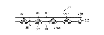
図3は、測定用基材2Mの長手方向DLの各位置での表面位置の一例を示すグラフであり、測定用基材2Mの長手方向DLを含む断面での断面構造と共に表面位置を示す図である。なお、図3では、幅方向DWの各部位のうち、長手方向DLに3つの波を有する部位の例を示す。
FIG. 3 is a graph showing an example of the surface position of the
図3が示すように、表面位置が測定される長手方向DLの各位置は、蒸着マスク用基材1の波形状を引き写すことの可能な間隔で並ぶ。表面位置が測定される長手方向DLの各位置は、例えば、長手方向DLに1mmの間隔で並ぶ。長手方向DLでの各位置の表面位置を結ぶ線LCは、蒸着マスク用基材1の表面に沿う線と見なされ、線LCの長さは、蒸着マスク用基材1の表面での沿面距離である。線LCに含まれる各波において、波における一方の谷から他方の谷までを結ぶ直線の長さは、波の長さL1,L2,L3である。線LCに含まれる各波において、波における谷間を結ぶ直線に対する高さは、波の高さH1,H2,H3である。蒸着マスク用基材1の単位急峻度は、波の長さに対する波の高さの百分率であり、図3に示す例では、高さH1/長さL1×100(%)、高さH2/長さL2×100(%)、および、高さH3/長さL3×100(%)である。蒸着マスク用基材1の急峻度は、幅方向DWの各位置において、長手方向DLに含まれる全ての波での単位急峻度の平均値である。図3に示す例では、蒸着マスク用基材1の急峻度は、高さH1/長さL1×100(%)、高さH2/長さL2×100(%)、および、高さH3/長さL3×100(%)の平均値である。
As shown in FIG. 3, each position of the longitudinal DL whose surface position is measured is arranged at intervals capable of copying the wave shape of the vapor deposition
図4は、蒸着マスク用基材1の幅方向DWでの各位置の急峻度を示す。図4の上段に示す実線は、幅方向DWでの中央部RCの急峻度が、両端部REの急峻度よりも大きい一例であり、図4の下段に示す実線は、幅方向DWでの一方の端部REの急峻度が、中央部RCの急峻度および他方の端部REの急峻度よりも大きい一例である。
FIG. 4 shows the steepness of each position of the vapor deposition
図4が示すように、蒸着マスク用基材1の急峻度は、幅方向DWの中央部RCで極大値を有し、中央部RCと端部REとの境界の付近で極小値を有する。そして、蒸着マスク用基材1の急峻度は、中央部RCから幅方向DWの両端部REに向けて増大する。幅方向DWの中央部RCは、蒸着マスク用基材1の幅方向DWでの中心PCを、中央部RCの幅方向DWでの中心とする。幅方向DWの中央部RCが有する幅方向DWでの長さは、蒸着マスク用基材1が有する幅方向DWでの長さの40%である。幅方向DWの各端部REが有する幅方向DWでの長さは、蒸着マスク用基材1が有する幅方向DWでの長さの30%である。こうした蒸着マスク用基材1の急峻度は、以下の3つの条件を満たす。
[条件1]幅方向DWでの中央部RCにおける急峻度の最大値が0.3%以下である。
[条件2]幅方向DWでの各端部REにおける急峻度の最大値が0.6%以下である。
[条件3]幅方向DWでの両端部REのなかの少なくとも一方での急峻度の最大値は、幅方向DWの中央部RCにおける急峻度の最大値よりも小さい。
As shown in FIG. 4, the steepness of the vapor deposition
[Condition 1] The maximum value of steepness in the central RC in the width direction DW is 0.3% or less.
[Condition 2] The maximum value of steepness at each end RE in the width direction DW is 0.6% or less.
[Condition 3] The maximum value of steepness at least one of both ends RE in the width direction DW is smaller than the maximum value of steepness in the central RC of the width direction DW.
図4の上段の実線が示すように、条件3を満たす例では、各端部REでの急峻度の最大値が、中央部RCでの急峻度の最大値よりも小さい。すなわち、蒸着マスク用基材1では、中央部RCの表面での波の起伏が、各端部REよりも激しい。こうした蒸着マスク用基材1は、蒸着マスク用基材1の表面に供給される液体を、中央部RCから各端部REへ、さらに、各端部REから蒸着マスク用基材1の外側へ流しやすい。
As shown by the solid line in the upper part of FIG. 4, in the example satisfying the
図4の下段の実線が示すように、条件3を満たす他の例では、一方の端部REでの急峻度の最大値が、中央部RCでの急峻度の最大値よりも小さく、かつ、他方の端部REでの急峻度の最大値が、中央部RCでの急峻度の最大値よりも大きい。すなわち、蒸着マスク用基材1では、一方の端部REの表面での波の起伏が、中央部RCよりも緩やかであり、かつ、他方の端部REの表面での波の起伏が、中央部RCよりも激しい。こうした蒸着マスク用基材1は、蒸着マスク用基材1の表面に供給される液体を、他方の端部REから一方の端部REへ、さらに、一方の端部REから蒸着マスク用基材1の外側へ流しやすい。
As shown by the solid line in the lower part of FIG. 4, in another example satisfying the
蒸着マスク用基材1の表面に供給される液体は、例えば、蒸着マスク用基材1の表面に位置するレジスト層を現像するための現像液、現像液を表面から除去するための洗浄液である。また、蒸着マスク用基材1の表面に供給される液体は、例えば、蒸着マスク用基材1をエッチングするためのエッチング液、エッチング液を表面から除去するための洗浄液である。また、蒸着マスク用基材1の表面に供給される液体は、例えば、蒸着マスク用基材1の表面にエッチング後に残存するレジスト層を剥離するための剥離液、剥離液を表面から除去するための洗浄液である。
The liquid supplied to the surface of the vapor deposition
そして、蒸着マスク用基材1の表面に供給された液体の流れに淀みを生じがたい上記各構成であれば、液体による処理を用いた加工の均一性を、蒸着マスク用基材1の表面内で高めることが可能となる。そのうえ、中央部RCの表面での起伏が過剰に激しくならないように、中央部RCが条件1を満たし、かつ、各端部REの表面での起伏が過剰に激しくならないように、各端部REが条件2を満たす構成であれば、レジスト層と蒸着マスク用基材1との密着性や、レジスト層に対する露光の精度を確保することが可能である。また、条件1および条件2を満たす構成であれば、蒸着マスク用基材1をロールトゥロール方式で搬送する際のズレを抑えることも可能であるから、液体の流れに淀みが生じ難いことと相まって、加工の均一性を一層に高めることが可能となる。
If each of the above configurations is such that the flow of the liquid supplied to the surface of the
なお、条件3を満たさない例では、各端部REでの急峻度の最大値が、中央部RCでの急峻度の最大値以上である。すなわち、両端部REの表面での波の起伏が、中央部RCの表面での波の起伏よりも激しい。こうした蒸着マスク用基材1では、蒸着マスク用基材1の表面に供給された液体が、各端部REから蒸着マスク用基材1の外側へ流れやすい一方で、各端部REから中央部RCへも流れやすい。結果として、中央部RCに液だまりを生じやすく、液体による処理を用いた加工の均一性を、蒸着マスク用基材1の表面内で低下させる要因となる。このように、条件3を満たす構成、および、それによって得られる効果は、中央部RCでの急峻度と各端部REでの急峻度との差によって発生する、液体を用いた表面の加工での課題を認識することによって、はじめて導き出されることである。
In the example in which the
[マスク装置の構成]
図5は、蒸着マスク用基材1を用いて製造される蒸着マスクを備えるマスク装置の概略的な平面構造を示す。図6は、蒸着マスクが備えるマスク部の断面構造の一例を示し、図7は、蒸着マスクが備えるマスク部の断面構造の他の例を示す。なお、マスク装置が備える蒸着マスクの数量や、蒸着マスク30が備えるマスク部の数量は一例である。
[Mask device configuration]
FIG. 5 shows a schematic planar structure of a masking apparatus including a vapor deposition mask manufactured by using the vapor deposition
図5が示すように、マスク装置10は、メインフレーム20と、3つの蒸着マスク30とを備える。メインフレーム20は、複数の蒸着マスク30を支持する矩形枠状を有し、蒸着を行うための蒸着装置に取り付けられる。メインフレーム20は、各蒸着マスク30が位置する範囲のほぼ全体にわたり、メインフレーム20を貫通するメインフレーム孔21を有する。
As shown in FIG. 5, the
各蒸着マスク30は、帯板状を有した複数のフレーム部31と、各フレーム部31に3体ずつのマスク部32とを備える。フレーム部31は、マスク部32を支持する短冊板状を有して、メインフレーム20に取り付けられる。フレーム部31は、マスク部32が位置する範囲のほぼ全体にわたり、フレーム部31を貫通するフレーム孔33を有する。フレーム部31は、マスク部32よりも高い剛性を有し、かつ、フレーム孔33を囲う枠状を有する。各マスク部32は、フレーム孔33を区画するフレーム部31のフレーム内縁部に1体ずつ、溶着や接着によって固定される。
Each
図6が示すように、マスク部32の一例は、マスク板323から構成される。マスク板323は、蒸着マスク用基材1から形成された1枚の板部材であってもよいし、蒸着マスク用基材1から形成された1枚の板部材と樹脂板との積層体であってもよい。なお、図6では、蒸着マスク用基材1から形成された1枚の板部材として示す。
As shown in FIG. 6, an example of the
マスク板323は、第1面321(図6の下面)と、第1面321とは反対側の面である第2面322(図6の上面)とを備える。第1面321は、マスク装置10が蒸着装置に取り付けられた状態で、ガラス基板などの蒸着対象と対向する。第2面322は、蒸着装置の蒸着源と対向する。マスク部32は、マスク板323を貫通する複数の孔32Hを有する。孔32Hの壁面は、マスク板323の厚み方向に対して、断面視において傾きを有する。孔32Hの壁面の形状は、断面視において、図6が示すように、孔32Hの外側に向けて張り出す半円弧状であってもよいし、複数の屈曲点を有する複雑な曲線状であってもよい。
The
マスク板323の厚みは、1μm以上50μm以下であり、好ましくは、2μm以上20μm以下である。マスク板323の厚みが50μm以下であれば、マスク板323に形成される孔32Hの深さを50μm以下とすることが可能である。このように、薄いマスク板323であれば、孔32Hが有する壁面の面積そのものを小さくして、孔32Hの壁面に付着する蒸着物質の体積を低下させることが可能である。
The thickness of the
第2面322は、孔32Hの開口である第2開口H2を含み、第1面321は、孔32Hの開口である第1開口H1を含む。第2開口H2は、平面視において、第1開口H1よりも大きい。各孔32Hは、蒸着源から昇華した蒸着物質が通る通路であって、蒸着源から昇華した蒸着物質は、第2開口H2から第1開口H1に向けて進む。第2開口H2が第1開口H1よりも大きい孔32Hであれば、第2開口H2から孔32Hに入る蒸着物質の量を増やすことが可能となる。なお、第1面321に沿う断面での孔32Hの面積は、第1開口H1から第2開口H2に向けて、第1開口H1から第2開口H2まで単調に増大してもよいし、第1開口H1から第2開口H2までの途中でほぼ一定となる部位を備えてもよい。
The
図7が示すように、マスク部32の他の例は、マスク板323を貫通する複数の孔32Hを有する。第2開口H2は、平面視において、第1開口H1よりも大きい。孔32Hは、第2開口H2を有する大孔32LHと、第1開口H1を有する小孔32SHとから構成される。大孔32LHの断面積は、第2開口H2から第1面321に向けて、単調に減少する。小孔32SHの断面積は、第1開口H1から第2面322に向けて、単調に減少する。孔32Hの壁面は、断面視において、大孔32LHと小孔32SHとが接続する部位、すなわち、マスク板323の厚み方向の中間で、孔32Hの内側に向けて突き出た形状を有する。孔32Hの壁面にて突き出た部位と、第1面321との間の距離は、ステップハイトSHである。なお、図6で説明した断面構造の例では、ステップハイトSHがゼロである。第1開口H1に到達する蒸着物質の量を確保しやすい観点では、ステップハイトSHがゼロである構成が好ましい。ステップハイトSHがゼロであるマスク部32を得る構成では、蒸着マスク用基材1の片面からのウェットエッチングで孔32Hが形成される程度に、マスク板323の厚みは薄く、例えば、50μm以下である。
As shown in FIG. 7, another example of the
[マスク部の接合構造]
図8は、マスク部32とフレーム部31との接合構造が有する断面構造の一例を示す。図9は、マスク部32とフレーム部31との接合構造が有する断面構造の他の例を示す。
[Joining structure of mask part]
FIG. 8 shows an example of the cross-sectional structure of the joint structure between the
図8が示す例のように、マスク板323の外縁部32Eは、孔32Hを備えない領域である。マスク板323が有する第2面322のなかでマスク板323の外縁部32Eに含まれる部分は、マスク部が備える側面の一例であり、フレーム部31に接合されている。フレーム部31は、フレーム孔33を区画する内縁部31Eを備える。内縁部31Eは、マスク板323と対向する接合面311(図8の下面)と、接合面311とは反対側の面である非接合面312(図8の上面)とを備える。内縁部31Eの厚みT31、すなわち、接合面311と非接合面312との距離は、マスク板323が有する厚みT32よりも十分に厚く、それによって、マスク板323よりも高い剛性をフレーム部31は有する。特に、フレーム部31は、内縁部31Eが自重によって垂れ下がることや、内縁部31Eがマスク部32に向けて変位することに対して、高い剛性を有する。内縁部31Eの接合面311は、第2面322と接合された接合部32BNを備える。
As in the example shown in FIG. 8, the
接合部32BNは、内縁部31Eのほぼ全周にわたり、連続的、あるいは、間欠的に位置する。接合部32BNは、接合面311と第2面322との溶着によって形成される溶着痕であってもよいし、接合面311と第2面322とを接合する接合層であってもよい。フレーム部31は、内縁部31Eの接合面311と、マスク板323の第2面322とを接合すると共に、マスク板323がそれの外側に向けて引っ張られるような応力Fを、マスク板323に加える。
The joint portion 32BN is continuously or intermittently located over almost the entire circumference of the
なお、フレーム部31もまた、それの外側に向けて引っ張られるような応力を、マスク板323での応力Fと同じ程度に、メインフレーム20によって加えられる。そのため、メインフレーム20から取り外された蒸着マスク30では、メインフレーム20とフレーム部31との接合による応力が解除され、マスク板323に加わる応力Fも緩和される。接合面311での接合部32BNの位置は、マスク板323に応力Fを等方的に作用させる位置であることが好ましく、マスク板323の形状、および、フレーム孔33の形状に基づき、適宜選択される。
The
接合面311は、接合部32BNが位置する平面であり、第2面322の外縁部32Eからマスク板323の外側に向けて広がる。言い換えれば、内縁部31Eは、第2面322がそれの外側へ擬似的に拡張された面構造を備え、第2面322の外縁部32Eから、マスク板323の外側に向けて広がる。そのため、接合面311が広がる範囲では、マスク板323の厚みに相当する空間Vが、マスク板323の周囲に形成されやすい。結果として、マスク板323の周囲では、蒸着対象Sとフレーム部31とが物理的に干渉することを抑えることが可能となる。
The
図9が示す例においても、第2面322の外縁部32Eは、孔32Hが形成されていない領域を備える。第2面322の外縁部32Eは、接合部32BNによる接合を通じて、フレーム部31が備える接合面311に接合される。そして、フレーム部31は、マスク板323がそれの外側に向けて引っ張られるような応力Fを、マスク板323に加えると共に、接合面311が広がる範囲において、マスク板323の厚みに相当する空間Vを形成する。
Also in the example shown in FIG. 9, the
なお、応力Fが作用しない状態でのマスク板323は、蒸着マスク用基材1と同じく、少なからず波形状を有する場合がある。そして、上述した応力Fが作用する状態でのマスク板323、すなわち、蒸着マスク30に搭載されたマスク板323は、波の高さを低くするように変形する場合がある。この点、上記条件2,3を満たす蒸着マスク用基材1であれば、応力Fによる変形が生じたとしても、それは許容される程度にまで抑えられ、結果として、蒸着マスク30での孔32Hの変形を抑えて、パターンの位置や形状の精度を高めることが可能ともなる。
The
[マスク部の数量]
図10は、蒸着マスク30が備える孔32Hの数量と、マスク部32が備える孔32Hの数量との関係の一例を示す。また、図11は、蒸着マスク30が備える孔32Hの数量と、マスク部32が備える孔32Hの数量との関係の他の例を示す。
[Quantity of mask part]
FIG. 10 shows an example of the relationship between the number of
図10(a)の例が示すように、フレーム部31は、3つのフレーム孔33(33A,33B,33C)を有する。図10(b)の例が示すように、蒸着マスク30は、各フレーム孔33に1つずつマスク部32(32A,32B,32C)を備える。フレーム孔33Aを区画する内縁部31Eは、1体のマスク部32Aと接合し、フレーム孔33Bを区画する内縁部31Eは、他の1体のマスク部32Bと接合し、フレーム孔33Cを区画する内縁部31Eは、他の1体のマスク部32Cと接合する。
As the example of FIG. 10A shows, the
ここで、蒸着マスク30は、複数の蒸着対象に対して、繰り返して用いられる。そのため、蒸着マスク30が備える各孔32Hは、孔32Hの位置や、孔32Hの構造などに、より高い精度を求められる。そして、孔32Hの位置や、孔32Hの構造などに、所望の精度を得られない場合には、蒸着マスク30の製造であれ、蒸着マスク30の補修であれ、マスク部32を適宜交換することが望まれる。
Here, the
この点、図10が示す構成のように、1体のフレーム部31に要する孔32Hの数量を、3体のマスク部32で分担する構成であれば、仮に、1体のマスク部32に交換を望まれた場合であっても、3体のマスク部32のうち、1体のマスク部32のみを交換すれば足りる。すなわち、3体のマスク部32のうち、2体のマスク部32を継続して利用することが可能となる。それゆえに、各フレーム孔33に別々のマスク部32を接合した構成であれば、蒸着マスク30の製造であれ、蒸着マスク30の補修であれ、これらに要する各種材料の消費量を抑えることが可能ともなる。マスク板323の厚みが薄いほど、また、孔32Hが小さいほど、マスク部32の歩留まりは下がりやすく、マスク部32に対する交換の要請は大きい。そのため、各フレーム孔33に別々のマスク部32を備える上記構成は、高解像度を求められる蒸着マスク30において、特に好適である。
In this regard, if the number of
なお、孔32Hの位置や、孔32Hの構造に関する検査は、応力Fが加えられた状態、すなわち、フレーム部31にマスク部32が接合された状態で行われることが好ましい。こうした観点において、上述した接合部32BNは、マスク部32の交換を可能とするように、例えば、内縁部31Eの一部に間欠的に存在することが好ましい。
It is preferable that the inspection regarding the position of the
図11(a)の例が示すように、フレーム部31は、3つのフレーム孔33を有する。図11(b)の例が示すように、蒸着マスク30は、各フレーム孔33に共通する1体のマスク部32を備えることも可能である。この際、フレーム孔33Aを区画する内縁部31E、フレーム孔33Bを区画する内縁部31E、フレーム孔33Cを区画する内縁部31Eは、これらに共通する1体のマスク部32と接合する。
As the example of FIG. 11A shows, the
なお、1体のフレーム部31に必要とされる孔32Hの数量を、1体のマスク部32で担う構成であれば、フレーム部31に接合されるマスク部32の数量を1体とすることが可能であるため、フレーム部31とマスク部32との接合に要する負荷を軽減することが可能である。マスク部32を構成するマスク板323の厚みが厚いほど、また、孔32Hのサイズが大きいほど、マスク部32の歩留まりが上がりやすく、マスク部32に対する交換の要請は小さい。そのため、各フレーム孔33に共通するマスク部32を備える構成は、低解像度を求められる蒸着マスク30において、特に好適である。
If the number of
[蒸着マスク用基材の製造方法]
次に、蒸着マスク用基材の製造方法について説明する。なお、蒸着マスク用基材の製造方法では、圧延を用いる形態と、電解を用いる形態とを別々に例示する。まず、圧延を用いる形態を説明し、次いで、電解を用いる形態を説明する。図12および図13は、圧延を用いる例を示す。
[Manufacturing method of base material for vapor deposition mask]
Next, a method for manufacturing a base material for a vapor deposition mask will be described. In the method for manufacturing the base material for a vapor-deposited mask, a form using rolling and a form using electrolysis are separately exemplified. First, a form using rolling will be described, and then a form using electrolysis will be described. 12 and 13 show an example of using rolling.
圧延を用いる製造方法では、図12が示すように、まず、インバーなどから形成された母材1aであって、長手方向DLに延びる母材1aを準備する。次いで、母材1aの長手方向DLと、母材1aを搬送する搬送方向とが平行になるように、圧延装置50に向けて母材1aを搬送する。圧延装置50は、例えば、一対の圧延ローラー51,52を備え、一対の圧延ローラー51,52で母材1aを圧延する。これによって、母材1aが長手方向DLに伸ばされて、圧延資材1bが形成される。圧延資材1bは、例えば、コアCに巻き取られてもよいし、帯形状に伸ばされた状態で取り扱われてもよい。圧延資材1bの厚みは、例えば、10μm以上50μm以下である。
In the manufacturing method using rolling, as shown in FIG. 12, first, a base material 1a formed from Invar or the like, which is a base material 1a extending in the longitudinal direction DL, is prepared. Next, the base metal 1a is conveyed toward the rolling
次いで、図13が示すように、圧延資材1bをアニール装置53に搬送する。アニール装置53は、圧延資材1bを長手方向DLに引っ張りながら加熱する。これによって、圧延資材1bの内部から、蓄積した残留応力が取り除かれ、蒸着マスク用基材1が形成される。この際、上記条件1,2,3が満たされるように、圧延ローラー51,52の間での押圧力、圧延ローラー51,52の回転速度、圧延資材1bのアニール温度などが設定される。
Next, as shown in FIG. 13, the rolling
電解を用いる製造方法では、電解に用いられる電極表面に蒸着マスク用基材1を形成し、その後、電極表面から蒸着マスク用基材1を離型する。蒸着マスク用基材1を構成する材料がインバーである場合、電解に用いられる電解浴は、鉄イオン供給剤、ニッケルイオン供給剤およびpH緩衝剤を含む。電解に用いられる電解浴は、応力緩和剤、Fe3+イオンマスク剤、リンゴ酸やクエン酸などの錯化剤などを含んでもよく、電解に適したpHに調整された弱酸性の溶液である。鉄イオン供給剤は、例えば、硫酸第一鉄・7水和物、塩化第一鉄、スルファミン酸鉄などである。ニッケルイオン供給剤は、例えば、硫酸ニッケル(II)、塩化ニッケル(II)、スルファミン酸ニッケル、臭化ニッケルである。pH緩衝剤は、例えば、ホウ酸、マロン酸である。マロン酸は、Fe3+イオンマスク剤としても機能する。応力緩和剤は、例えばサッカリンナトリウムである。電解に用いられる電解浴は、例えば、上述した添加剤を含む水溶液であり、5%硫酸、あるいは、炭酸ニッケルなどのpH調整剤によって、例えば、pHが2以上3以下となるように調整される。
In the manufacturing method using electrolysis, the
電解に用いられる電解条件では、蒸着マスク用基材1の厚み、蒸着マスク用基材1の組成比などに応じて、電解浴の温度、電流密度および電解時間が適宜調整される。上述した電解浴に適用される陽極は、例えば、純鉄製とニッケル製である。上述した電解浴に適用される陰極は、例えば、SUS304などのステンレス板である。電解浴の温度は、例えば、40℃以上60℃以下である。電流密度は、例えば、1A/dm2以上4A/dm2以下である。この際、上記条件1,2,3が満たされるよう、電極表面での電流密度が設定される。
Under the electrolysis conditions used for electrolysis, the temperature, current density, and electrolysis time of the electrolysis bath are appropriately adjusted according to the thickness of the
なお、電解による蒸着マスク用基材1や、圧延による蒸着マスク用基材1は、化学的な研磨や、電気的な研磨によって、さらに薄く加工されてもよい。化学的な研磨に用いられる研磨液は、例えば、過酸化水素を主成分とした鉄系合金用の化学研磨液である。電気的な研磨に用いられる電解液は、過塩素酸系の電解研磨液や硫酸系の電解研磨液である。この際、上記条件1,2,3が満たされるため、研磨液による研磨の結果や、洗浄液による研磨液の洗浄の結果について、蒸着マスク用基材1の表面でのばらつきが抑えられる。
The thin-film deposition
[マスク部の製造方法]
図7に示したマスク部32を製造するための工程について図14から図19を参照して説明する。なお、図6で説明したマスク部32を製造するための工程は、図7で説明したマスク部32を製造するための工程にて、小孔32SHを貫通孔として、大孔32LHを形成するための工程を割愛した工程と同様であるため、その重複する説明を割愛する。
[Manufacturing method of mask part]
The process for manufacturing the
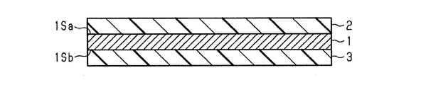
図14が示すように、マスク部を製造するときには、まず、第1面1Saと第2面1Sbとを含む蒸着マスク用基材1と、第1面1Saに貼り付けられる第1ドライフィルムレジスト(Dry Film Resist:DFR)2と、第2面1Sbに貼り付けられる第2ドライフィルムレジスト(DFR)3とが準備される。DFR2,3の各々は、蒸着マスク用基材1とは別に形成される。次いで、第1面1Saに第1DFR2が貼り付けられ、かつ、第2面1Sbに第2DFR3が貼り付けられる。
As shown in FIG. 14, when manufacturing the mask portion, first, a vapor deposition
図15が示すように、DFR2,3のうち、孔を形成する部位以外の部分を露光し、露光後のDFRを現像する。これによって、第1DFR2に第1貫通孔2aを形成し、かつ、第2DFR3に第2貫通孔3aを形成する。露光後のDFRを現像するときには、現像液として、例えば、炭酸ナトリウム水溶液を用いる。この際、上記条件1,2,3が満たされるため、現像液による現像の結果や、その洗浄液による洗浄の結果について、蒸着マスク用基材1の表面でのばらつきが抑えられる。結果として、第1貫通孔2aの形状や大きさ、また、第2貫通孔3aの形状や大きさに関して、蒸着マスク用基材1の表面内での均一性を高めることが可能となる。
As shown in FIG. 15, a portion of
図16が示すように、例えば、現像後の第1DFR2をマスクとして、塩化第二鉄液を用いて蒸着マスク用基材1の第1面1Saをエッチングする。このとき、第2面1Sbが第1面1Saと同時にエッチングされないように、第2面1Sbに第2保護層61を形成する。第2保護層61の材料は、塩化第二鉄液に対する化学的な耐性を有する。これによって、第2面1Sbに向けて窪む小孔32SHを第1面1Saに形成する。小孔32SHは、第1面1Saに開口する第1開口H1を有する。この際、上記条件1,2,3が満たされるため、エッチング液によるエッチングの結果や、その洗浄液による洗浄の結果について、蒸着マスク用基材1の表面でのばらつきを抑えられる。結果として、小孔32SHの形状や大きさに関して、蒸着マスク用基材1の表面内での均一性を高めることが可能となる。
As shown in FIG. 16, for example, the first surface 1Sa of the
蒸着マスク用基材1をエッチングするエッチング液は、酸性のエッチング液であって、蒸着マスク用基材1がインバーから構成される場合には、インバーをエッチングすることが可能なエッチング液であればよい。酸性のエッチング液は、例えば、過塩素酸第二鉄液および過塩素酸第二鉄液と塩化第二鉄液との混合液に対して、過塩素酸、塩酸、硫酸、蟻酸および酢酸のいずれかを混合した溶液である。蒸着マスク用基材1をエッチングする方法は、蒸着マスク用基材1を酸性のエッチング液に浸漬するディップ式であってもよいし、蒸着マスク用基材1に酸性のエッチング液を吹き付けるスプレー式であってもよい。
The etching solution for etching the
次いで、図17が示すように、第1面1Saに形成した第1DFR2と、第2DFR3に接する第2保護層61とを取り除く。また、第1面1Saのさらなるエッチングを防ぐための第1保護層4を第1面1Saに形成する。第1保護層4の材料は、塩化第二鉄液に対する化学的な耐性を有する。
Next, as shown in FIG. 17, the first DFR2 formed on the first surface 1Sa and the second protective layer 61 in contact with the second DFR3 are removed. Further, the first
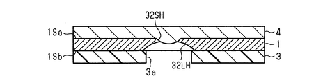
次に、図18が示すように、現像後の第2DFR3をマスクとして、塩化第二鉄液を用いて第2面1Sbをエッチングする。これによって、第1面1Saに向けて窪む大孔32LHを第2面1Sbに形成する。大孔32LHは、第2面1Sbに開口する第2開口H2を有する。第2面1Sbと対向する平面視において、第2開口H2は、第1開口H1よりも大きい。この際、上記条件1,2,3が満たされるため、エッチング液によるエッチングの結果や、洗浄液によるエッチング液の洗浄の結果について、蒸着マスク用基材1の表面でのばらつきが抑えられる。結果として、大孔32LHの形状や大きさについて、蒸着マスク用基材1の表面内での均一性を高めることが可能となる。この際に用いられるエッチング液もまた、酸性のエッチング液であって、蒸着マスク用基材1がインバーから構成される場合には、インバーをエッチングすることが可能なエッチング液であればよい。蒸着マスク用基材1をエッチングする方法もまた、蒸着マスク用基材1を酸性のエッチング液に浸漬するディップ式であってもよいし、蒸着マスク用基材1に酸性のエッチング液を吹き付けるスプレー式であってもよい。
Next, as shown in FIG. 18, the second surface 1Sb is etched with the ferric chloride solution using the developed second DFR3 as a mask. As a result, a large hole 32LH recessed toward the first surface 1Sa is formed on the second surface 1Sb. The foramen magnum 32LH has a second opening H2 that opens into the second surface 1Sb. The second opening H2 is larger than the first opening H1 in a plan view facing the second surface 1Sb. At this time, since the
次いで、図19が示すように、第1保護層4と第2DFR3とを蒸着マスク用基材1から取り除くことによって、複数の小孔32SHと、各小孔32SHに繋がる大孔32LHとが形成されたマスク部32が得られる。
Next, as shown in FIG. 19, by removing the first
なお、圧延を用いる製造方法では、酸化アルミニウムや酸化マグネシウムなどの金属酸化物が、蒸着マスク用基材1のなかに少なからず含まれる。すなわち、上述した母材1aが形成されるとき、通常、母材1aのなかに酸素が混入することを抑えるため、粒状のアルミニウムやマグネシウムなどの脱酸剤が、原料に混ぜられる。そして、アルミニウムやマグネシウムは、酸化アルミニウムや酸化マグネシウムなどの金属酸化物として、母材1aに少なからず残る。この点、電解を用いる製造方法によれば、金属酸化物がマスク部32に混ざることが抑えられる。
In the manufacturing method using rolling, metal oxides such as aluminum oxide and magnesium oxide are contained in the vapor deposition
[蒸着マスクの製造方法]
蒸着マスクの製造方法の各例を説明する。なお、図20を参照して、ウェットエッチングによって孔を形成する方法での例(第1製造方法)を説明する。また、図21を参照して、電解によって孔を形成する方法での例(第2製造方法)を説明する。また、図22を参照して、電解によって孔を形成する方法での他の例(第3製造方法)を説明する。
[Manufacturing method of thin-film mask]
Each example of the manufacturing method of the vapor deposition mask will be described. In addition, an example (the first manufacturing method) of the method of forming a hole by wet etching will be described with reference to FIG. Further, with reference to FIG. 21, an example (second manufacturing method) of the method of forming holes by electrolysis will be described. Further, another example (third manufacturing method) in the method of forming holes by electrolysis will be described with reference to FIG. 22.
[第1製造方法]
なお、図6で説明したマスク部32を備える蒸着マスクを製造する方法と、図7で説明したマスク部32を備える蒸着マスクを製造する方法とは、基材32Kに対して行われるエッチングの形態が異なるが、それ以外の工程はほぼ同様である。以下では、図6で説明したマスク部32を備える蒸着マスクの製造方法を主に説明し、図7で説明したマスク部32を備える蒸着マスクの製造方法に関しては、その重複した説明を省略する。
[First manufacturing method]
The method of manufacturing the thin-film deposition mask including the
図20(a)〜(h)が示す例のように、蒸着マスクの製造方法の一例では、まず、基材32Kが準備される(図20(a)参照)。なお、基材32Kは、マスク板323として加工される上述した蒸着マスク用基材1の他に、その蒸着マスク用基材1を支持するための支持体SPをさらに備えることが好ましい。なお、基材32Kの第1面321(図20の下面)は、上記第1面1Saに相当し、基材32Kの第2面322(図20の上面)は、上記第2面1Sbに相当する。
As in the example shown in FIGS. 20 (a) to 20 (h), in one example of the method for manufacturing a vapor deposition mask, first, a
まず、基材32Kが有する第2面322にレジスト層PRを形成し(図20(b)参照)、レジスト層PRに対する露光および現像を行うことによって、第2面322にレジストマスクRMを形成する(図20(c)参照)。次に、レジストマスクRMを用いた第2面322からのウェットエッチングによって、基材32Kに孔32Hが形成される(図20(d)参照)。
First, a resist layer PR is formed on the
この際、ウェットエッチングが開始される第2面322には、第2開口H2が形成され、それよりも遅れてエッチングが行われる第1面321には、第2開口H2よりも小さい第1開口H1が形成される。次いで、レジストマスクRMが第2面322から除去されることによって、上記マスク部32が形成される(図20(e)参照)。最後に、第2面322における外縁部32Eが、フレーム部31の内縁部31Eに接合され、マスク部32から支持体SPが離型されることによって、蒸着マスク30が製造される(図20(f)から(h)参照)。
At this time, the second opening H2 is formed on the
なお、図7で説明したマスク部32を備える蒸着マスクの製造方法では、上述した工程が、支持体SPを有さない基材32Kにおいて、第1面321に対応する基材32Kの面に施され、それによって、小孔32SHが形成される。次いで、小孔32SHを保護するためのレジストなどが小孔32SHに充填される。続いて、上述した工程が、第2面322に対応する基材32Kの面に施され、それによって、マスク部32が製造される。
In the method for manufacturing a vapor deposition mask including the
なお、図20(f)が示す例では、第2面322の外縁部32Eをフレーム部31の内縁部31Eに接合する方法として、抵抗溶接を用いる。この際、絶縁性を有した支持体SPに、複数の孔SPHを形成する。各孔SPHは、支持体SPのなかで、接合部32BNとなる部位と対向する部位に形成される。そして、各孔SPHを通じて通電し、間欠的な接合部32BNを形成する。これによって、外縁部32Eと内縁部31Eとを溶着する。
In the example shown in FIG. 20 (f), resistance welding is used as a method of joining the
また、図20(g)が示す例では、第2面322の外縁部32Eをフレーム部31の内縁部31Eに接合する方法として、レーザー溶接を用いる。この際、光透過性を有した支持体SPを用い、支持体SPを通じて、接合部32BNとなる部位にレーザー光Lを照射する。そして、外縁部32Eの周囲でレーザー光Lを間欠的に照射することによって、間欠的な接合部32BNを形成する。あるいは、外縁部32Eの周囲でレーザー光Lを連続的に照射し続けることによって、外縁部32Eの全周にわたり、連続的な接合部32BNを形成する。これによって、外縁部32Eと内縁部31Eとを溶着する。
Further, in the example shown in FIG. 20 (g), laser welding is used as a method of joining the
また、図20(h)が示す例では、第2面322の外縁部32Eをフレーム部31の内縁部31Eに接合する方法として、超音波溶接を用いる。この際、外縁部32Eと内縁部31Eとを、クランプCPなどで挟持し、接合部32BNとなる部位に、超音波を印加する。超音波が直接印加される部材は、フレーム部31であってもよいし、マスク部32であってもよい。なお、超音波溶接が用いられた場合には、フレーム部31や支持体SPに、クランプCPによる圧着痕が形成される。
Further, in the example shown in FIG. 20 (h), ultrasonic welding is used as a method of joining the
なお、上述した各接合では、マスク部32に対してそれの外側に向けた応力を加えた状態で、溶着や溶接を行うことも可能である。また、マスク部32に対してそれの外側に向けた応力を加えた状態で、支持体SPがマスク部32を支持している場合には、マスク部32に対する応力の印加を割愛することも可能である。
In each of the above-mentioned joints, welding or welding can be performed on the
[第2製造方法]
図8および図9で説明した蒸着マスクは、上記第1製造方法の他に、図21(a)〜(e)で示す他の例によって製造することも可能である。
図21(a)〜(e)が示す例のように、まず、電解に用いられる電極EPの表面である電極表面EPSに、レジスト層PRを形成する(図21(a)参照)。次いで、レジスト層PRに対する露光および現像を行うことによって、電極表面EPSにレジストマスクRMを形成する(図21(b)参照)。レジストマスクRMは、電極表面EPSと直交する断面において逆錐台状を有し、電極表面EPSからの距離が大きいほど、電極表面EPSに沿った断面での面積が大きい形状を有する。次に、レジストマスクRMを有した電極表面EPSを用いる電解を行い、電極表面EPSのなかでレジストマスクRM以外の領域に、マスク部32を形成する(図21(c)参照)。
[Second manufacturing method]
The vapor deposition mask described with reference to FIGS. 8 and 9 can be manufactured by other examples shown in FIGS. 21 (a) to 21 (e) in addition to the first manufacturing method.
As in the examples shown in FIGS. 21 (a) to 21 (e), first, a resist layer PR is formed on the electrode surface EPS, which is the surface of the electrode EP used for electrolysis (see FIG. 21 (a)). Next, a resist mask RM is formed on the electrode surface EPS by exposing and developing the resist layer PR (see FIG. 21 (b)). The resist mask RM has an inverted cone shape in a cross section orthogonal to the electrode surface EPS, and the larger the distance from the electrode surface EPS, the larger the area in the cross section along the electrode surface EPS. Next, electrolysis is performed using the electrode surface EPS having the resist mask RM, and the
この際、レジストマスクRMが占有する空間以外にマスク部32を形成するため、レジストマスクRMの形状に追従した形状を有する孔が、マスク部32には形成される。すなわち、マスク部32の孔32Hが、マスク部32において自己整合的に形成される。そして、電極表面EPSと接触する面が、第1開口H1を有する第1面321として機能し、第1開口H1よりも大きい開口である第2開口H2を有する最表面が、第2面322として機能する。
At this time, since the
次に、電極表面EPSからレジストマスクRMのみを除去して、第1開口H1から第2開口H2までを中空とする孔32Hを形成する(図21(d)参照)。最後に、第2開口H2を有した第2面322の外縁部32Eに、内縁部31Eの接合面311を接合し、次いで、マスク部32を電極表面EPSから剥がすための応力をフレーム部31に加える。これによって、フレーム部31にマスク部32が接合された状態の蒸着マスク30を製造する(図21(e)参照)。
Next, only the resist mask RM is removed from the electrode surface EPS to form a
[第3製造方法]
図8および図9で説明した蒸着マスクは、上記第1製造方法の他に、図21(a)〜(e)で示す他の例によって製造することも可能である。
図22(a)〜(f)が示す例のように、まず、電解に用いられる電極表面EPSにレジスト層PRを形成する(図22(a)参照)。次いで、レジスト層PRに対する露光および現像を行うことによって、電極表面EPSにレジストマスクRMを形成する(図22(b)参照)。レジストマスクRMは、電極表面EPSと直交する断面において錐台状を有し、電極表面EPSからの距離が大きいほど、電極表面EPSに沿った断面での面積が小さい形状を有する。次に、レジストマスクRMを有した電極表面EPSを用いる電解を行い、電極表面EPSのなかでレジストマスクRM以外の領域に、マスク部32を形成する(図22(c)参照)。
[Third manufacturing method]
The vapor deposition mask described with reference to FIGS. 8 and 9 can be manufactured by other examples shown in FIGS. 21 (a) to 21 (e) in addition to the first manufacturing method.
As shown in the examples shown in FIGS. 22 (a) and 22 (f), first, a resist layer PR is formed on the electrode surface EPS used for electrolysis (see FIG. 22 (a)). Next, a resist mask RM is formed on the electrode surface EPS by exposing and developing the resist layer PR (see FIG. 22 (b)). The resist mask RM has a frustum shape in a cross section orthogonal to the electrode surface EPS, and the larger the distance from the electrode surface EPS, the smaller the area in the cross section along the electrode surface EPS. Next, electrolysis is performed using the electrode surface EPS having the resist mask RM, and the
ここでも、レジストマスクRMが占有する空間以外にマスク部32を形成するため、レジストマスクRMの形状に追従した形状を有する孔が、マスク部32には形成される。すなわち、マスク部32における孔32Hが、マスク部32において自己整合的に形成される。そして、電極表面EPSと接触する面が、第2開口H2を有する第2面322として機能し、第2開口H2よりも小さい開口である第1開口H1を有する最表面が、第1面321として機能する。
Here, too, since the
次に、電極表面EPSからレジストマスクRMのみを除去して、第1開口H1から第2開口H2までを中空とする孔32Hを形成する(図22(d)参照)。そして、第1開口H1を有した第1面321に、中間転写基材TMを接合し、次いで、マスク部32を電極表面EPSから剥がすための応力を中間転写基材TMに加える。これによって、中間転写基材TMにマスク部32が接合された状態で、電極表面EPSから第2面322が離される(図22(e)参照)。最後に、第2面322の外縁部32Eに、内縁部31Eの接合面311を接合し、中間転写基材TMをマスク部32から外す。これによって、フレーム部31にマスク部32が接合された状態の蒸着マスク30を製造する(図22(f)参照)。
Next, only the resist mask RM is removed from the electrode surface EPS to form a
上述した蒸着マスク30を用いて表示装置を製造する方法では、まず、蒸着マスク30を搭載したマスク装置10を蒸着装置の真空槽内に取り付ける。この際、ガラス基板などの蒸着対象と第1面321とが対向するように、かつ、蒸着源と第2面322とが対向するように、マスク装置10を取り付ける。そして、蒸着装置の真空槽に蒸着対象を搬入し、蒸着源で蒸着物質を昇華させる。これによって、第1開口H1に追従した形状を有するパターンが、第1開口H1と対向する蒸着対象に形成される。なお、蒸着物質は、例えば、表示装置の画素を構成する有機発光材料や、表示装置の画素回路を構成する画素電極などである。
In the method of manufacturing a display device using the
[実施例]
図23から図29を参照して各実施例を説明する。
[実施例1]
まず、インバーを材料とする母材1aに圧延工程を施して金属板を形成し、次いで、幅方向DWに所望の大きさが得られるように、金属板を切断するスリット工程を行い、圧延資材1bを形成した。続いて、圧延資材1bにアニール工程を施して、幅方向DWの長さが500mmであり、かつ、厚みが20μmである実施例1の蒸着マスク用基材1を得た。
[Example]
Each embodiment will be described with reference to FIGS. 23 to 29.
[Example 1]
First, a rolling process is performed on the base material 1a using Inver as a material to form a metal plate, and then a slitting process for cutting the metal plate is performed so that a desired size can be obtained in the width direction DW, and the rolling material is rolled. 1b was formed. Subsequently, the rolling
次いで、図23が示すように、長手方向DLの長さが700mmである実施例1の測定用基材2Mを、実施例1の蒸着マスク用基材1から切り出した。続いて、切り出された測定用基材2Mの急峻度を、測定用基材2Mの幅方向DWの全体にわたり測定した。この際、急峻度の測定条件として、以下に示す条件を用いた。
測定装置:株式会社ニコン製 CNC画像測定システム VMR−6555
計測範囲ZLの長手方向DLの長さ :500mm
非計測範囲ZEの長手方向DLの長さ :100mm
長手方向DLの測定間隔 :1mm
幅方向DWの測定間隔 :20mm
実施例1の急峻度の測定結果を図24および表1に示す。なお、表1が示す急峻度は、中央部RCおよび各端部REでの最大値である。
Next, as shown in FIG. 23, the
Measuring device: CNC image measuring system VMR-6555 manufactured by Nikon Corporation
Measurement range ZL longitudinal DL length: 500 mm
Length of non-measurement range ZE in the longitudinal direction DL: 100 mm
Longitudinal DL measurement interval: 1 mm
Measurement interval of DW in the width direction: 20 mm
The measurement results of the steepness of Example 1 are shown in FIG. 24 and Table 1. The steepness shown in Table 1 is the maximum value at the central RC and each end RE.
図24が示すように、実施例1の中央部RCでの急峻度の最大値は、0.3%以下であり、各端部REでの急峻度の最大値は、0.6%以下であり、上記条件1,2を満たすことが認められた。そして、実施例1では、両端部REのなかの一方(端部1)での急峻度の最大値が、0.43%であり、中央部RCでの急峻度の最大値(0.28%)よりも大きいことが認められた。これに対して、両端部REのなかの他方(端部2)での急峻度の最大値が、0.20%であり、中央部RCでの急峻度よりも小さいことが認められた。すなわち、上記条件3を満たすことが認められた。なお、両端部REでの急峻度の最大値の差は、0.23%であった。
As shown in FIG. 24, the maximum value of steepness at the central RC of Example 1 is 0.3% or less, and the maximum value of steepness at each end RE is 0.6% or less. It was confirmed that the
[実施例2]
圧延ローラー51,52の間での押圧力を実施例1よりも高め、その他の条件を実施例1の条件と同様に設定することによって、幅方向DWの長さが500mmであり、かつ、厚みが15μmである実施例2の蒸着マスク用基材1を得た。次いで、実施例1と同様に、実施例2の蒸着マスク用基材1から測定用基材2Mを切り出し、切り出された測定用基材2Mの急峻度を、測定用基材2Mの幅方向DWの全体にわたり測定した。
実施例2の急峻度の測定結果を図25および表1に示す。
[Example 2]
By increasing the pressing force between the rolling
The measurement results of the steepness of Example 2 are shown in FIG. 25 and Table 1.
図25が示すように、実施例2の中央部RCでの急峻度の最大値は、0.3%以下であり、各端部REでの急峻度の最大値は、0.6%以下であり、上記条件1,2を満たすことが認められた。そして、実施例2では、両端部REでの急峻度の最大値が、0.15%と0.06%とであり、中央部RCでの急峻度の最大値(0.17%)よりも小さく、上記条件3を満たすことが認められた。
As shown in FIG. 25, the maximum value of steepness at the central RC of Example 2 is 0.3% or less, and the maximum value of steepness at each end RE is 0.6% or less. It was confirmed that the
[実施例3]
圧延ローラー51,52の間での押圧力を実施例1よりも高め、かつ、実施例2とは異なる分布とし、その他の条件を実施例1の条件と同様に設定することによって、幅方向DWの長さが500mmであり、かつ、厚みが15μmである実施例3の蒸着マスク用基材1を得た。次いで、実施例1と同様に、実施例3の蒸着マスク用基材1から測定用基材2Mを切り出し、切り出された測定用基材2Mの急峻度を、測定用基材2Mの幅方向DWの全体にわたり測定した。
実施例3の急峻度の測定結果を図26および表1に示す。
[Example 3]
By increasing the pressing force between the rolling
The measurement results of the steepness of Example 3 are shown in FIG. 26 and Table 1.
図26が示すように、実施例3の中央部RCでの急峻度の最大値は、0.3%以下であり、各端部REでの急峻度の最大値は、0.6%以下であり、上記条件1,2を満たすことが認められた。そして、実施例3では、両端部REのなかの一方(端部1)での急峻度の最大値が、0.58%であり、中央部RCでの急峻度の最大値(0.24%)よりも大きいことが認められた。これに対して、両端部REのなかの他方(端部2)での急峻度の最大値が、0.21%であり、中央部RCでの急峻度の最大値よりも小さいことが認められた。すなわち、上記条件3を満たすことが認められた。なお、両端部REでの急峻度の最大値の差は、0.37%であった。
As shown in FIG. 26, the maximum value of steepness at the central RC of Example 3 is 0.3% or less, and the maximum value of steepness at each end RE is 0.6% or less. It was confirmed that the
[比較例1]
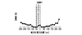
圧延ローラー51,52の間での押圧力を実施例1よりも高め、かつ、圧延ローラー51,52の回転速度を実施例1よりも高め、その他の条件を実施例1の条件と同様に設定することによって、幅方向DWの長さが500mmであり、かつ、厚みが20μmである比較例1の蒸着マスク用基材1を得た。次いで、実施例1と同様に、比較例1の蒸着マスク用基材1から測定用基材2Mを切り出し、切り出された測定用基材2Mの沿面距離を、測定用基材2Mの幅方向DWの全体にわたり測定して、比較例1の測定用基材2Mでの急峻度を得た。
比較例1の急峻度の測定結果を図27および表1に示す。
[Comparative Example 1]
The pressing force between the rolling
The measurement results of the steepness of Comparative Example 1 are shown in FIG. 27 and Table 1.
図27が示すように、比較例1の中央部RCでの急峻度の最大値は、0.3%以下であり、各端部REでの急峻度の最大値は、0.6%以下であり、上記条件1,2を満たすことが認められた。一方、比較例1では、両端部REでの急峻度の最大値が、0.21%と0.36%とであり、中央部RCでの急峻度の最大値(0.08%)よりも大きく、上記条件3を満たさないことも認められた。
As shown in FIG. 27, the maximum value of steepness at the central RC of Comparative Example 1 is 0.3% or less, and the maximum value of steepness at each end RE is 0.6% or less. It was confirmed that the
[比較例2]
圧延ローラー51,52の間での押圧力の分布を比較例1から変更し、その他の条件を比較例1の条件と同様に設定することによって、幅方向DWの長さが500mmであり、かつ、厚みが20μmである比較例2の蒸着マスク用基材1を得た。次いで、比較例1と同様に、比較例2の蒸着マスク用基材1から測定用基材2Mを切り出し、切り出された測定用基材2Mの急峻度を、測定用基材2Mの幅方向DWの全体にわたり測定した。
比較例2の急峻度の測定結果を図28および表1に示す。
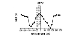
[Comparative Example 2]
By changing the distribution of the pressing force between the rolling
The measurement results of the steepness of Comparative Example 2 are shown in FIG. 28 and Table 1.
図28が示すように、比較例2の中央部RCでの急峻度の最大値は、0.3%を大幅に超える大きさであり、各端部REでの急峻度の最大値は、0.6%以下であり、上記条件2を満たす一方で、上記条件1を満たさないことが認められた。そして、比較例2では、両端部REでの急峻度の最大値が、0.59%と0.58%とであり、中央部RCでの急峻度の最大値(0.63%)よりも小さく、上記条件3を満たしていることが認められた。
As shown in FIG. 28, the maximum value of the steepness at the central RC of Comparative Example 2 is a magnitude significantly exceeding 0.3%, and the maximum value of the steepness at each end RE is 0. It was found that the content was 6.6% or less, and while the
[比較例3]
圧延ローラー51,52の間での押圧力の分布を比較例1から変更し、その他の条件を比較例1の条件と同様に設定することによって、幅方向DWの長さが500mmであり、かつ、厚みが20μmである比較例3の蒸着マスク用基材1を得た。次いで、比較例1と同様に、比較例3の蒸着マスク用基材1から測定用基材2Mを切り出し、切り出された測定用基材2Mの急峻度を、測定用基材2Mの幅方向DWの全体にわたり測定した。
比較例3の急峻度の測定結果を図29および表1に示す。
[Comparative Example 3]
By changing the distribution of the pressing force between the rolling
The measurement results of the steepness of Comparative Example 3 are shown in FIG. 29 and Table 1.
図29が示すように、比較例3の中央部RCが有する急峻度の最大値は、0.3%以下であり、両端部REのなかの一方(端部1)での急峻度の最大値は、0.6%を大幅に超える大きさであり、両端部のなかの他方(端部2)での急峻度の最大値は、0.6%以下であることが認められた。すなわち、上記条件1を満たす一方で、上記条件2を満たさないことが認められた。そして、比較例3の両端部REでの急峻度の最大値は、0.81%と0.36%とであり、中央部RCでの急峻度の最大値よりも大きいことが認められた。すなわち、上記条件3が満たされないことが認められた。
As shown in FIG. 29, the maximum value of steepness of the central RC of Comparative Example 3 is 0.3% or less, and the maximum value of steepness at one of both ends RE (end 1). Was significantly larger than 0.6%, and it was found that the maximum value of steepness at the other end (end 2) of both ends was 0.6% or less. That is, it was found that while the

[パターンの精度]
各実施例1,2,3および各比較例1,2,3の蒸着マスク用基材1を用い、蒸着マスク用基材1の第1面1Saに、厚さが10μmの第1DFR2を貼り着けた。次いで、第1DFR2に露光マスクを接触させて露光する露光工程、次いで現像工程を施し、30μmの直径を有した複数の貫通孔2aを、第1DFR2に格子状に形成した。続いて、第1DFR2をマスクとするエッチングを第1面1Saに施して、格子状に位置する複数の孔32Hを蒸着マスク用基材1に形成した。そして、蒸着マスク用基材1の幅方向DWでの開口径を各孔32Hについて計測した。各孔32Hの幅方向DWでの開口径のばらつきを表1に示す。なお、表1では、各孔32Hが有する開口径のなかで、開口径の最大値と開口径の最小値との差が2.0μm以下である水準に○印を記載し、開口径の最大値と開口径の最小値との差が2.0μmよりも大きい水準に×印を記載した。
[Pattern accuracy]
Using the vapor deposition
表1が示すように、各実施例1,2,3では、開口径のばらつきがいずれも2.0μm以下であることが認められた。他方、各比較例1,2,3では、開口径のばらつきがいずれも2.0μmよりも大きいことが認められた。 As shown in Table 1, in each of Examples 1, 2 and 3, it was found that the variation in the opening diameter was 2.0 μm or less. On the other hand, in Comparative Examples 1, 2 and 3, it was found that the variation in the opening diameter was larger than 2.0 μm.
なお、比較例1では、各端部REでの急峻度の最大値が、中央部RCでの急峻度の最大値よりも大きく、条件3が満たされていない。そのため、比較例1では、条件1,2が満たされてはいるが、液体の流れに淀みを形成する構成であるがため、開口径のばらつきは、2.0μmよりも大きい。
In Comparative Example 1, the maximum value of the steepness at each end RE is larger than the maximum value of the steepness at the central RC, and the
また、比較例2では、各端部REでの急峻度の最大値が、中央部RCでの急峻度の最大値よりも小さく、条件3が満たされている一方で、中央部RCでの急峻度の最大値が、0.3%よりも大幅に大きく、条件1が満たされていない。そのため、条件2,3が満たされてはいるが、中央部RCでの波の高さなどが過大であることに起因して、中央部RCの波の谷など、中央部RCそのものにおいて、液体の流れに淀みを形成してしまい、開口径のばらつきは、2.0μmよりも大きい。
Further, in Comparative Example 2, the maximum value of the steepness at each end RE is smaller than the maximum value of the steepness at the central RC, and the
また、比較例3では、比較例1と同じく、各端部REでの急峻度の最大値が、中央部RCでの急峻度の最大値よりも大きく、条件3が満たされていない。また、一方の端部REでの急峻度の最大値が、0.6%よりも大幅に大きく、条件2が満たされていない。そのため、比較例3では、条件1が満たされてはいるが、液体の流れにおける淀み、レジスト層の剥がれ、レジスト層に対する露光ずれ、蒸着マスク用基材1の搬送ずれなどに起因し、開口径のばらつきは、2.0μmよりも大きい。
Further, in Comparative Example 3, as in Comparative Example 1, the maximum value of the steepness at each end portion RE is larger than the maximum value of the steepness at the central portion RC, and the
結果として、これら実施例1,2,3と比較例1との比較からは、幅方向DWでの両端部REのなかの少なくとも一方での急峻度の最大値が、幅方向DWの中央部RCにおける急峻度の最大値よりも小さいこと、すなわち、条件3が満たされることによって、開口径のばらつきが抑えられることが認められた。言い換えれば、条件1,2が満たされるような、急峻度の最大値が小さい蒸着マスク用基材1であっても、上記条件3を満たさない構成では、少なからず存在する急峻度の分布に起因して、すなわち、液体の流れの淀みなどに起因して、開口径にばらつきが生じてしまうことも認められた。
As a result, from the comparison between Examples 1, 2 and 3 and Comparative Example 1, the maximum value of the steepness of at least one of the both ends RE in the width direction DW is the central portion RC of the width direction DW. It was found that the variation in the opening diameter was suppressed by being smaller than the maximum value of the steepness in the above, that is, satisfying the
また、実施例1,2,3と比較例2,3との比較からは、条件3を満たすことによって上述した効果を得るためには、中央部RCにおける急峻度の最大値が0.3%以下であり、各端部REにおける急峻度の最大値が0.6%以下であること、すなわち、条件1,2を満たす必要があることが認められた。言い換えれば、条件3が満たされるような、急峻度の最大値に好適な分布を有する蒸着マスク用基材1であっても、上記条件1,2を満たさない構成では、過大な起伏を有する波が存在することに起因して、開口径にばらつきが生じてしまうことも認められた。
Further, from the comparison between Examples 1, 2 and 3 and Comparative Examples 2 and 3, in order to obtain the above-mentioned effect by satisfying the
上記実施形態によれば、以下に列挙する効果が得られる。
(1)マスク部32が備える孔の形状や孔の大きさに関わる精度を高めること、ひいては、蒸着によって形成されるパターンの精度を高めることが可能となる。なお、レジストを露光する方法は、レジストに露光マスクを接触させる方法に限らず、レジストに露光マスクを接触させない露光であってもよい。レジストに露光マスクを接触させる方法であれば、露光マスクの表面に蒸着マスク用基材が押し付けられるため、蒸着マスク用基材が備える波形状に起因した露光精度の低下を抑えられる。いずれの露光方法であっても、液体で表面を加工する工程での精度は高められ、ひいては、蒸着によって形成されるパターンの精度を高めることが可能となる。
According to the above embodiment, the effects listed below can be obtained.
(1) It is possible to improve the accuracy of the hole shape and the hole size of the
(2)現像液による現像の結果や、その洗浄液による洗浄の結果について、蒸着マスク用基材1の表面でのばらつきを抑えられる。結果として、露光工程と現像工程とを経て形成される第1貫通孔2aや第2貫通孔3aについて、その形状や大きさの均一性を、蒸着マスク用基材1の表面内で高めることが可能となる。
(2) It is possible to suppress variations in the surface of the thin-film deposition
(3)エッチング液によるエッチングの結果や、その洗浄液によるエッチング液の洗浄の結果について、蒸着マスク用基材1の表面でのばらつきを抑えられる。また、剥離液によるレジスト層の剥離の結果や、その洗浄液による剥離液の洗浄の結果について、蒸着マスク用基材1の表面でのばらつきを抑えられる。結果として、小孔32SHの形状や大きさ、また、大孔32LHの形状や大きさに関して、蒸着マスク用基材1の表面内での均一性を高めることが可能となる。
(3) It is possible to suppress variations in the surface of the
(4)1体のフレーム部31に必要とされる孔32Hの数量を、例えば、3体のマスク部32で担う。すなわち、1体のフレーム部31に必要とされるマスク部32の総面積を、例えば、3体のマスク部32に分割している。そのため、1体のフレーム部31においてマスク部32の一部に変形が生じた場合であっても、1体のフレーム部31の全てのマスク部32を交換する必要はない。そして、変形したマスク部32と交換される新たなマスク部32の大きさを、1体のフレーム部31に1体のマスク部32を備える構成と比べて、1/3程度に小さくすることが可能ともなる。
(4) For example, three
(5)測定用基材2Mを用いた急峻度の測定では、測定用基材2Mの長手方向DLでの両方の端部を、非計測範囲ZEとして、急峻度の測定対象から除外している。各非計測範囲ZEは、蒸着マスク用基材1の切断によって、蒸着マスク用基材1とは異なる波形状を有する可能性を有した範囲である。そのため、非計測範囲ZEを測定対象から除外する測定であれば、急峻度の精度を高めることが可能である。
(5) In the measurement of steepness using the
なお、上記実施形態は、以下のように変更することも可能である。
[蒸着マスク用基材の製造方法]
・圧延工程では、複数の対の圧延ローラーを備えた圧延装置を用い、複数の対の圧延ローラーによって母材1aを圧延することも可能である。複数の対の圧延ローラーを用いる方法であれば、上記条件1,2,3を満たすための制御パラメータに関して、自由度を高めることが可能ともなる。
The above embodiment can be changed as follows.
[Manufacturing method of base material for vapor deposition mask]
-In the rolling process, it is also possible to use a rolling apparatus provided with a plurality of pairs of rolling rollers to roll the base metal 1a with a plurality of pairs of rolling rollers. If the method uses a plurality of pairs of rolling rollers, it is possible to increase the degree of freedom regarding the control parameters for satisfying the
・アニール工程では、圧延資材1bを長手方向DLに引っ張りながらアニールを行うのではなく、コアCに巻き取られたロール状の圧延資材1bをアニールすることも可能である。なお、ロール状の圧延資材1bをアニールする方法では、蒸着マスク用基材1に、ロール径に応じた反りの癖が付く場合がある。そのため、蒸着マスク用基材1の材料や、コアCに巻かれたときのロール径の大きさによっては、圧延資材1bを引っ張りながらアニールすることが好ましい。
・圧延工程とアニール工程とを複数回にわたり交互に繰り返すことによって、蒸着マスク用基材1を製造することも可能である。
-In the annealing step, it is also possible to anneal the rolled rolling
-It is also possible to manufacture the
・電解による蒸着マスク用基材1や、圧延による蒸着マスク用基材1は、化学的な研磨や、電気的な研磨によって、さらに薄く加工されてもよい。この際、研磨の工程を含めて上記条件1,2,3が満たされるよう、研磨液の組成やそれの供給の方式などの条件を設定することも可能である。
The
[中央部RCおよび端部RE]
・中央部RCの幅方向DWでの長さは、蒸着マスク用基材1の幅方向DWでの長さの40%であることが好ましい。ただし、中央部RCの幅方向DWでの長さは、蒸着マスク用基材1の幅方向DWでの長さの例えば20%以上60%以下とすることも可能である。
[Central RC and edge RE]
The length of the central portion RC in the width direction DW is preferably 40% of the length of the vapor deposition
・端部REの幅方向DWでの長さは、蒸着マスク用基材1の幅方向DWでの長さの30%であることが好ましい。ただし、端部REの幅方向DWでの長さは、蒸着マスク用基材1の幅方向DWでの長さの例えば20%以上40%以下とすることも可能であり、この範囲において、一方の端部REと他方の端部REとの間で互いに異なる長さを有することも可能である。
The length of the end portion RE in the width direction DW is preferably 30% of the length of the vapor deposition
C…コア、F…応力、S…蒸着対象、V…空間、W…寸法、CP…クランプ、DL…長手方向、DW…幅方向、EP…電極、H1…第1開口、H2…第2開口、PC…中心、PR…レジスト層、RC…中央部、RE…端部、RM…レジストマスク、SH…ステップハイト、SP…支持体、TM…中間転写基材、ZE…非計測範囲、ZL…計測範囲、EPS…電極表面、1…蒸着マスク用基材、1a…母材、1b…圧延資材、1Sa,321…第1面、1Sb,322…第2面、2…測定用基材、2a…第1貫通孔、2S…表面、3a…第2貫通孔、4…第1保護層、10…マスク装置、20…メインフレーム、21…メインフレーム孔、30…蒸着マスク、31…フレーム部、31E…内縁部、32,32A,32B,32C…マスク部、32BN…接合部、32E…外縁部、32H…孔、32K…基材、32LH…大孔、32SH…小孔、33,33A,33B,33C…フレーム孔、50…圧延装置、51,52…圧延ローラー、53…アニール装置、61…第2保護層、311…接合面、312…非接合面、323…マスク板。 C ... core, F ... stress, S ... vapor deposition target, V ... space, W ... dimensions, CP ... clamp, DL ... longitudinal direction, DW ... width direction, EP ... electrode, H1 ... first opening, H2 ... second opening , PC ... center, PR ... resist layer, RC ... center, RE ... edge, RM ... resist mask, SH ... step height, SP ... support, TM ... intermediate transfer substrate, ZE ... non-measurement range, ZL ... Measurement range, EPS ... Electrode surface, 1 ... Deposition mask base material, 1a ... Base material, 1b ... Rolling material, 1Sa, 321 ... First surface, 1Sb, 322 ... Second surface, 2 ... Measurement base material, 2a ... 1st through hole, 2S ... surface, 3a ... 2nd through hole, 4 ... first protective layer, 10 ... mask device, 20 ... main frame, 21 ... main frame hole, 30 ... vapor deposition mask, 31 ... frame part, 31E ... Inner edge, 32, 32A, 32B, 32C ... Mask, 32BN ... Join, 32E ... Outer edge, 32H ... Hole, 32K ... Base material, 32LH ... Large hole, 32SH ... Small hole, 33, 33A, 33B , 33C ... Frame hole, 50 ... Rolling device, 51, 52 ... Rolling roller, 53 ... Annealing device, 61 ... Second protective layer, 311 ... Bonded surface, 312 ... Non-bonded surface, 323 ... Mask plate.
Claims (6)
前記金属板を構成する材料は、ニッケルまたは鉄ニッケル合金であり、
前記金属板の厚みは、10μm以上50μm以下であり、
前記金属板の幅方向での各位置における前記金属板の長手方向に沿った形状は、相互に異なっており、各形状は、前記金属板の長手方向に繰り返す波を有し、
前記波における一方の谷から他方の谷までを結ぶ直線の長さが波の長さであり、
前記波の長さに対する前記波の高さの百分率が単位急峻度であり、
前記金属板の前記幅方向の各位置において、前記長手方向に含まれる全ての波での単位急峻度の平均値が急峻度であり、
前記金属板の前記幅方向において、中央部が2つの端部に挟まれ、
前記中央部が有する前記幅方向での長さは、前記金属板が有する前記幅方向での長さの40%であり、
各端部が有する前記幅方向での長さは、前記金属板が有する前記幅方向での長さの30%であり、
一方の前記端部での急峻度の最大値、および、他方の前記端部での急峻度の最大値は、前記中央部での急峻度の最大値よりも小さく、
各端部での急峻度の最大値、および、前記中央部での急峻度の最大値は、0.2%以下である
蒸着マスク用基材。 A base material for a vapor deposition mask, which is a metal plate having a strip shape and has a plurality of holes formed by etching and is used for manufacturing a vapor deposition mask.
The material constituting the metal plate is nickel or an iron-nickel alloy.
The thickness of the metal plate is 10 μm or more and 50 μm or less.
The shapes along the longitudinal direction of the metal plate at each position in the width direction of the metal plate are different from each other, and each shape has a wave repeating in the longitudinal direction of the metal plate.
The length of the straight line connecting one valley to the other in the wave is the length of the wave.
The percentage of the height of the wave with respect to the length of the wave is the unit steepness.
At each position in the width direction of the metal plate, the average value of the unit steepness in all waves included in said longitudinal direction is steepness,
In the width direction of the metal plate, the central portion is sandwiched between the two ends.
The length of the central portion in the width direction is 40% of the length of the metal plate in the width direction.
The length of each end in the width direction is 30% of the length of the metal plate in the width direction.
The maximum value of steepness at one end and the maximum value of steepness at the other end are smaller than the maximum value of steepness at the center.
The maximum value of the steepness at each end portion and the maximum value of the steepness at the central portion are 0.2% or less .
母材を圧延して前記金属板を得ることを含み、
前記金属板を構成する材料は、ニッケルまたは鉄ニッケル合金であり、
前記金属板の厚みは、10μm以上50μm以下であり、
前記金属板の幅方向での各位置における前記金属板の長手方向に沿った形状は、相互に異なっており、各形状は、前記金属板の長手方向に繰り返す波を有し、
前記波における一方の谷から他方の谷までを結ぶ直線の長さが波の長さであり、
前記波の長さに対する前記波の高さの百分率が単位急峻度であり、
前記金属板の前記幅方向の各位置において、前記長手方向に含まれる全ての波での単位急峻度の平均値が急峻度であり、
前記金属板の前記幅方向において、中央部が2つの端部に挟まれ、
前記中央部が有する前記幅方向での長さは、前記金属板が有する前記幅方向での長さの40%であり、
各端部が有する前記幅方向での長さは、前記金属板が有する前記幅方向での長さの30%であり、
前記金属板を得ることでは、
一方の前記端部での急峻度の最大値、および、他方の前記端部での急峻度の最大値は、前記中央部での急峻度の最大値よりも小さく、
各端部での急峻度の最大値、および、前記中央部での急峻度の最大値は、0.2%以下であるように、前記母材を圧延する、
蒸着マスク用基材の製造方法。 A method for manufacturing a base material for a thin-film deposition mask, which is a metal plate having a strip shape, in which a plurality of holes are formed by etching and used for manufacturing a thin-film deposition mask.
Including rolling the base metal to obtain the metal plate
The material constituting the metal plate is nickel or an iron-nickel alloy.
The thickness of the metal plate is 10 μm or more and 50 μm or less.
The shapes along the longitudinal direction of the metal plate at each position in the width direction of the metal plate are different from each other, and each shape has a wave repeating in the longitudinal direction of the metal plate.
The length of the straight line connecting one valley to the other in the wave is the length of the wave.
The percentage of the height of the wave with respect to the length of the wave is the unit steepness.
At each position in the width direction of the metal plate, the average value of the unit steepness in all waves included in said longitudinal direction is steepness,
In the width direction of the metal plate, the central portion is sandwiched between the two ends.
The length of the central portion in the width direction is 40% of the length of the metal plate in the width direction.
The length of each end in the width direction is 30% of the length of the metal plate in the width direction.
In obtaining the metal plate,
The maximum value of steepness at one end and the maximum value of steepness at the other end are smaller than the maximum value of steepness at the center.
The base metal is rolled so that the maximum value of the steepness at each end portion and the maximum value of the steepness at the central portion are 0.2% or less.
A method for manufacturing a base material for a vapor deposition mask.
前記レジスト層をマスクとしたエッチングによって前記金属板に複数の孔を形成してマスク部を形成することと、を含む蒸着マスクの製造方法であって、
前記金属板を構成する材料は、ニッケルまたは鉄ニッケル合金であり、
前記金属板の厚みは、10μm以上50μm以下であり、
前記金属板の幅方向での各位置における前記金属板の長手方向に沿った形状は、相互に異なっており、各形状は、前記金属板の長手方向に繰り返す波を有し、
前記波における一方の谷から他方の谷までを結ぶ直線の長さが波の長さであり、
前記波の長さに対する前記波の高さの百分率が単位急峻度であり、
前記金属板の前記幅方向の各位置において、前記長手方向に含まれる全ての波での単位急峻度の平均値が急峻度であり、
前記金属板の前記幅方向において、中央部が2つの端部に挟まれ、
前記中央部が有する前記幅方向での長さは、前記金属板が有する前記幅方向での長さの40%であり、
各端部が有する前記幅方向での長さは、前記金属板が有する前記幅方向での長さの30%であり、
一方の前記端部での急峻度の最大値、および、他方の前記端部での急峻度の最大値は、前記中央部での急峻度の最大値よりも小さく、
各端部での急峻度の最大値、および、前記中央部での急峻度の最大値は、0.2%以下である
蒸着マスクの製造方法。 Forming a resist layer on a strip-shaped metal plate and
A method for manufacturing a vapor-deposited mask, which comprises forming a mask portion by forming a plurality of holes in the metal plate by etching using the resist layer as a mask.
The material constituting the metal plate is nickel or an iron-nickel alloy.
The thickness of the metal plate is 10 μm or more and 50 μm or less.
The shapes along the longitudinal direction of the metal plate at each position in the width direction of the metal plate are different from each other, and each shape has a wave repeating in the longitudinal direction of the metal plate.
The length of the straight line connecting one valley to the other in the wave is the length of the wave.
The percentage of the height of the wave with respect to the length of the wave is the unit steepness.
At each position in the width direction of the metal plate, the average value of the unit steepness in all waves included in said longitudinal direction is steepness,
In the width direction of the metal plate, the central portion is sandwiched between the two ends.
The length of the central portion in the width direction is 40% of the length of the metal plate in the width direction.
The length of each end in the width direction is 30% of the length of the metal plate in the width direction.
The maximum value of steepness at one end and the maximum value of steepness at the other end are smaller than the maximum value of steepness at the center.
A method for manufacturing a thin-film deposition mask , wherein the maximum value of steepness at each end portion and the maximum value of steepness at the central portion are 0.2% or less.
前記各マスク部が、前記複数の孔を有した1つの側面を別々に備え、
前記各マスク部の側面と、1体のフレーム部とを、前記複数の孔を前記マスク部ごとに前記1体のフレーム部が囲うように、相互に接合することをさらに含む
請求項3に記載の蒸着マスクの製造方法。 Forming the mask portion means forming a plurality of the mask portions on a single metal plate.
Each mask portion separately comprises one side surface having the plurality of holes.
3. The third aspect of the present invention further comprises joining the side surface of each mask portion and one frame portion to each other so that the plurality of holes are surrounded by the one frame portion for each mask portion. How to make a vapor deposition mask.
前記レジスト層をマスクとしたエッチングによって前記金属板に複数の孔を形成してマスク部を形成することと、を含む蒸着マスクの製造方法であって、 A method for manufacturing a vapor-deposited mask, which comprises forming a mask portion by forming a plurality of holes in the metal plate by etching using the resist layer as a mask.
前記金属板を構成する材料は、ニッケルまたは鉄ニッケル合金であり、 The material constituting the metal plate is nickel or an iron-nickel alloy.
前記金属板の厚みは、10μm以上50μm以下であり、 The thickness of the metal plate is 10 μm or more and 50 μm or less.
前記金属板の幅方向での各位置における前記金属板の長手方向に沿った形状は、相互に異なっており、各形状は、前記金属板の長手方向に繰り返す波を有し、 The shapes along the longitudinal direction of the metal plate at each position in the width direction of the metal plate are different from each other, and each shape has a wave repeating in the longitudinal direction of the metal plate.
前記波における一方の谷から他方の谷までを結ぶ直線の長さが波の長さであり、 The length of the straight line connecting one valley to the other in the wave is the length of the wave.
前記波の長さに対する前記波の高さの百分率が単位急峻度であり、 The percentage of the height of the wave with respect to the length of the wave is the unit steepness.
前記金属板の幅方向の各位置において、前記長手方向に含まれる全ての波での単位急峻度の平均値が急峻度であり、 At each position in the width direction of the metal plate, the average value of the unit steepness in all the waves included in the longitudinal direction is the steepness.
前記金属板の前記幅方向において、中央部が2つの端部に挟まれ、 In the width direction of the metal plate, the central portion is sandwiched between the two ends.
前記中央部が有する前記幅方向での長さは、前記金属板が有する前記幅方向での長さの40%であり、 The length of the central portion in the width direction is 40% of the length of the metal plate in the width direction.
各端部が有する前記幅方向での長さは、前記金属板が有する前記幅方向での長さの30%であり、 The length of each end in the width direction is 30% of the length of the metal plate in the width direction.
前記中央部における急峻度の最大値が、0.3%以下であり、 The maximum value of steepness in the central portion is 0.3% or less.
各端部における急峻度の最大値が、0.6%以下であり、 The maximum value of steepness at each end is 0.6% or less,
前記金属板の前記幅方向での両端部のなかの少なくとも一方での急峻度の最大値は、前記金属板の前記幅方向の中央部における急峻度の最大値よりも小さく、 The maximum value of steepness at least one of both ends of the metal plate in the width direction is smaller than the maximum value of steepness in the central portion of the metal plate in the width direction.
前記マスク部を形成することは、単一の前記金属板に複数の前記マスク部を形成することであり、 Forming the mask portion means forming a plurality of the mask portions on a single metal plate.
前記各マスク部が、前記複数の孔を有した1つの側面を別々に備え、 Each mask portion separately comprises one side surface having the plurality of holes.
前記各マスク部の側面と、1体のフレーム部とを、前記複数の孔を前記マスク部ごとに前記1体のフレーム部が囲うように、相互に接合することをさらに含む Further comprising joining the side surface of each mask portion and one frame portion to each other so that the plurality of holes are surrounded by the one frame portion for each mask portion.
蒸着マスクの製造方法。 Manufacturing method of thin-film mask.
前記蒸着マスクを用いた蒸着によってパターンを形成することとを含む
表示装置の製造方法。 Preparing a vapor deposition mask according to the method for manufacturing a vapor deposition mask according to any one of claims 3 to 5.
A method for manufacturing a display device, which comprises forming a pattern by vapor deposition using the vapor deposition mask.
Priority Applications (1)
| Application Number | Priority Date | Filing Date | Title |
|---|---|---|---|
| JP2018072336A JP6984529B2 (en) | 2017-09-08 | 2018-04-04 | A base material for a vapor deposition mask, a method for manufacturing a base material for a vapor deposition mask, a method for manufacturing a vapor deposition mask, and a method for manufacturing a display device. |
Applications Claiming Priority (2)
| Application Number | Priority Date | Filing Date | Title |
|---|---|---|---|
| JP2017173153A JP6319505B1 (en) | 2017-09-08 | 2017-09-08 | Vapor deposition mask substrate, vapor deposition mask substrate production method, vapor deposition mask production method, and display device production method |
| JP2018072336A JP6984529B2 (en) | 2017-09-08 | 2018-04-04 | A base material for a vapor deposition mask, a method for manufacturing a base material for a vapor deposition mask, a method for manufacturing a vapor deposition mask, and a method for manufacturing a display device. |
Related Parent Applications (1)
| Application Number | Title | Priority Date | Filing Date |
|---|---|---|---|
| JP2017173153A Division JP6319505B1 (en) | 2017-09-08 | 2017-09-08 | Vapor deposition mask substrate, vapor deposition mask substrate production method, vapor deposition mask production method, and display device production method |
Publications (3)
| Publication Number | Publication Date |
|---|---|
| JP2019049044A JP2019049044A (en) | 2019-03-28 |
| JP2019049044A5 JP2019049044A5 (en) | 2020-10-22 |
| JP6984529B2 true JP6984529B2 (en) | 2021-12-22 |
Family
ID=79193340
Family Applications (1)
| Application Number | Title | Priority Date | Filing Date |
|---|---|---|---|
| JP2018072336A Active JP6984529B2 (en) | 2017-09-08 | 2018-04-04 | A base material for a vapor deposition mask, a method for manufacturing a base material for a vapor deposition mask, a method for manufacturing a vapor deposition mask, and a method for manufacturing a display device. |
Country Status (1)
| Country | Link |
|---|---|
| JP (1) | JP6984529B2 (en) |
Family Cites Families (4)
| Publication number | Priority date | Publication date | Assignee | Title |
|---|---|---|---|---|
| JP5455099B1 (en) * | 2013-09-13 | 2014-03-26 | 大日本印刷株式会社 | Metal plate, metal plate manufacturing method, and mask manufacturing method using metal plate |
| JP6598007B2 (en) * | 2015-09-30 | 2019-10-30 | 日立金属株式会社 | Method for producing Fe-Ni alloy thin sheet |
| WO2017154981A1 (en) * | 2016-03-09 | 2017-09-14 | 日立金属株式会社 | Martensitic stainless steel foil and method for manufacturing same |
| CN110144547B (en) * | 2016-04-14 | 2021-06-01 | 凸版印刷株式会社 | Substrate for vapor deposition mask, method for producing substrate for vapor deposition mask, and method for producing vapor deposition mask |
-
2018
- 2018-04-04 JP JP2018072336A patent/JP6984529B2/en active Active
Also Published As
| Publication number | Publication date |
|---|---|
| JP2019049044A (en) | 2019-03-28 |
Similar Documents
| Publication | Publication Date | Title |
|---|---|---|
| JP6939431B2 (en) | A base material for a vapor deposition mask, a method for manufacturing a base material for a vapor deposition mask, and a method for manufacturing a vapor deposition mask. | |
| TWI766114B (en) | Vapor deposition mask substrate, vapor deposition mask substrate manufacturing method, vapor deposition mask manufacturing method, and display device manufacturing method | |
| JP6299922B1 (en) | Vapor deposition mask substrate, vapor deposition mask substrate production method, vapor deposition mask production method, and display device production method | |
| KR102312461B1 (en) | Vapor deposition mask substrate, vapor deposition mask substrate manufacturing method, vapor deposition mask manufacturing method, and display device manufacturing method | |
| JP6988565B2 (en) | A base material for a vapor deposition mask, a method for manufacturing a base material for a vapor deposition mask, a method for manufacturing a vapor deposition mask, and a method for manufacturing a display device. | |
| JP6981302B2 (en) | A base material for a vapor deposition mask, a method for manufacturing a base material for a vapor deposition mask, a method for manufacturing a vapor deposition mask, and a method for manufacturing a display device. | |
| JP6984529B2 (en) | A base material for a vapor deposition mask, a method for manufacturing a base material for a vapor deposition mask, a method for manufacturing a vapor deposition mask, and a method for manufacturing a display device. |
Legal Events
| Date | Code | Title | Description |
|---|---|---|---|
| A521 | Written amendment |
Free format text: JAPANESE INTERMEDIATE CODE: A523 Effective date: 20200908 |
|
| A621 | Written request for application examination |
Free format text: JAPANESE INTERMEDIATE CODE: A621 Effective date: 20200908 |
|
| TRDD | Decision of grant or rejection written | ||
| A01 | Written decision to grant a patent or to grant a registration (utility model) |
Free format text: JAPANESE INTERMEDIATE CODE: A01 Effective date: 20211026 |
|
| A61 | First payment of annual fees (during grant procedure) |
Free format text: JAPANESE INTERMEDIATE CODE: A61 Effective date: 20211108 |
|
| R150 | Certificate of patent or registration of utility model |
Ref document number: 6984529 Country of ref document: JP Free format text: JAPANESE INTERMEDIATE CODE: R150 |