JP6983889B2 - Surgical stapler - Google Patents
Surgical stapler Download PDFInfo
- Publication number
- JP6983889B2 JP6983889B2 JP2019531542A JP2019531542A JP6983889B2 JP 6983889 B2 JP6983889 B2 JP 6983889B2 JP 2019531542 A JP2019531542 A JP 2019531542A JP 2019531542 A JP2019531542 A JP 2019531542A JP 6983889 B2 JP6983889 B2 JP 6983889B2
- Authority
- JP
- Japan
- Prior art keywords
- clamp arm
- latch
- handle
- staple
- surgical instrument
- Prior art date
- Legal status (The legal status is an assumption and is not a legal conclusion. Google has not performed a legal analysis and makes no representation as to the accuracy of the status listed.)
- Active
Links
Images


Classifications
-
- A—HUMAN NECESSITIES
- A61—MEDICAL OR VETERINARY SCIENCE; HYGIENE
- A61B—DIAGNOSIS; SURGERY; IDENTIFICATION
- A61B17/00—Surgical instruments, devices or methods, e.g. tourniquets
- A61B17/068—Surgical staplers, e.g. containing multiple staples or clamps
- A61B17/072—Surgical staplers, e.g. containing multiple staples or clamps for applying a row of staples in a single action, e.g. the staples being applied simultaneously
- A61B17/07207—Surgical staplers, e.g. containing multiple staples or clamps for applying a row of staples in a single action, e.g. the staples being applied simultaneously the staples being applied sequentially
-
- A—HUMAN NECESSITIES
- A61—MEDICAL OR VETERINARY SCIENCE; HYGIENE
- A61B—DIAGNOSIS; SURGERY; IDENTIFICATION
- A61B17/00—Surgical instruments, devices or methods, e.g. tourniquets
- A61B17/28—Surgical forceps
- A61B17/2812—Surgical forceps with a single pivotal connection
- A61B17/2833—Locking means
-
- A—HUMAN NECESSITIES
- A61—MEDICAL OR VETERINARY SCIENCE; HYGIENE
- A61B—DIAGNOSIS; SURGERY; IDENTIFICATION
- A61B17/00—Surgical instruments, devices or methods, e.g. tourniquets
- A61B17/068—Surgical staplers, e.g. containing multiple staples or clamps
-
- A—HUMAN NECESSITIES
- A61—MEDICAL OR VETERINARY SCIENCE; HYGIENE
- A61B—DIAGNOSIS; SURGERY; IDENTIFICATION
- A61B17/00—Surgical instruments, devices or methods, e.g. tourniquets
- A61B17/28—Surgical forceps
- A61B17/29—Forceps for use in minimally invasive surgery
- A61B17/2909—Handles
-
- A—HUMAN NECESSITIES
- A61—MEDICAL OR VETERINARY SCIENCE; HYGIENE
- A61B—DIAGNOSIS; SURGERY; IDENTIFICATION
- A61B17/00—Surgical instruments, devices or methods, e.g. tourniquets
- A61B2017/00477—Coupling
-
- A—HUMAN NECESSITIES
- A61—MEDICAL OR VETERINARY SCIENCE; HYGIENE
- A61B—DIAGNOSIS; SURGERY; IDENTIFICATION
- A61B17/00—Surgical instruments, devices or methods, e.g. tourniquets
- A61B2017/00526—Methods of manufacturing
- A61B2017/0053—Loading magazines or sutures into applying tools
-
- A—HUMAN NECESSITIES
- A61—MEDICAL OR VETERINARY SCIENCE; HYGIENE
- A61B—DIAGNOSIS; SURGERY; IDENTIFICATION
- A61B17/00—Surgical instruments, devices or methods, e.g. tourniquets
- A61B17/068—Surgical staplers, e.g. containing multiple staples or clamps
- A61B17/072—Surgical staplers, e.g. containing multiple staples or clamps for applying a row of staples in a single action, e.g. the staples being applied simultaneously
- A61B2017/07214—Stapler heads
- A61B2017/07278—Stapler heads characterised by its sled or its staple holder
-
- A—HUMAN NECESSITIES
- A61—MEDICAL OR VETERINARY SCIENCE; HYGIENE
- A61B—DIAGNOSIS; SURGERY; IDENTIFICATION
- A61B17/00—Surgical instruments, devices or methods, e.g. tourniquets
- A61B17/068—Surgical staplers, e.g. containing multiple staples or clamps
- A61B17/072—Surgical staplers, e.g. containing multiple staples or clamps for applying a row of staples in a single action, e.g. the staples being applied simultaneously
- A61B2017/07214—Stapler heads
- A61B2017/07285—Stapler heads characterised by its cutter
Description
(関連出願の相互参照)
本出願は、2016年8月29日付けで出願された米国仮特許出願第62/380,746号の利益を主張するものであり、その全体が、参照により本明細書に組み込まれる。
(Mutual reference of related applications)
This application claims the benefit of US Provisional Patent Application No. 62 / 380,746 filed dated August 29, 2016, which is incorporated herein by reference in its entirety.
現在、外科医は、肺、食道、胃、十二指腸及び/又は腸管内の他の器官などの体組織を縫合するためにステープル留め器具を使用している。適切なステープル留め器具の使用は、より優れた作業を短時間で行い、胃腸吻合などの以前は困難であった外科手術を単純化することができる。これらのステープル留め器具の1つには、線形切断ステープラ又は線形カッタが含まれ得る。線形切断ステープラ又は線形カッタは、創傷閉鎖、並びに内部組織閉鎖及び切除のための外科手術において使用することができる。典型的な直線切断用ステープラは、余分な組織を除去(例えば、切断によって)することができ、創傷を閉鎖(例えば、ステープラによって)することができるように、ステープル留め及び切断することができる。そのような線形切断ステープラは、一般に、2つの顎部(すなわち、上部顎部及び下部顎部)、上部顎部及び下部顎部をクランプ又は閉鎖するためのクランプ又は閉鎖ハンドル、上部顎部及び下部顎部の前端部又は遠位端部それぞれに互いに対向して配置されたステープルアンビル及びステープルカートリッジ、ステープルカートリッジ内に配置され、ステープルカートリッジに対して同期的に移動可能である発射片及びカッタ、並びに発射部品及びカッタの移動を駆動するためのアクチュエータ又は発射機構、を含む。典型的には、ステープルはステープルカートリッジ内に配置され、発射片がステープルプッシャーを連続的に押し、ステープルをステープルアンビルに向けて押し、カッタがステープルカートリッジとステープルアンビルとの間の組織を切断する。あいにく、現在の線形切断ステープラ又は線形カッタでは、手術を行うとき、使用前に顎部が連結解除される可能性があるか又は顎部を組み立てるのが困難になる可能性があり、より厚い組織ではクランプするのが困難になる可能性があり、その操作は、片手はもちろん両手でも困難になる可能性がある。 Surgeons are now using staples to suture body tissues such as lungs, esophagus, stomach, duodenum and / or other organs in the intestinal tract. The use of proper staples can perform better tasks in less time and simplify previously difficult surgical procedures such as gastroenterostomy. One of these staple fasteners may include a linear cutting stapler or a linear cutter. Linear cutting staplers or cutters can be used in wound closure, as well as surgery for internal tissue closure and resection. A typical linear cutting stapler can be stapled and cut so that excess tissue can be removed (eg, by cutting) and the wound can be closed (eg, by stapler). Such linear cutting staplers generally have two jaws (ie, upper and lower jaws), a clamp or closure handle for clamping or closing the upper and lower jaws, an upper jaw and a lower part. Staple anvils and staple cartridges located opposite each other at the anterior or distal ends of the jaw, projectiles and cutters located within the staple cartridge and movable synchronously with respect to the staple cartridge, and Includes actuators or launch mechanisms for driving the movement of launch components and cutters. Typically, the staples are placed within the staple cartridge, the projectile continuously pushes the staple pusher, pushing the staples towards the staple anvil, and the cutter cutting the tissue between the staple cartridge and the staple anvil. Unfortunately, with current linear cutting staplers or linear cutters, when performing surgery, the jaw may be disconnected or difficult to assemble before use, resulting in thicker tissue. Can be difficult to clamp, and its operation can be difficult with one or both hands.
線形カッタ又はステープラなどの外科用器具を提供することができる。実施例では、外科用器具は、最大顎部開口部を制限することができ、並びに本明細書に記載されるように片手クランプ及び使用のために構成することができる。更に、実施例では、外科用器具の及び形成され得るハウジング部分及び/又は顎部(例えば、顎部の一部であり得るか又は顎部であり得るアンビル及び/又はステープルカートリッジ)並びにそれらのエンドエフェクタは、近位ラッチなどのラッチ及びそれに関連付けられた構成要素を介して連結されたままであることができ、ハウジング部分及び顎部は、組織をクランプアーム及びそれに関連付けられた構成要素を介してクランプし、ステープル留めし、切開することができるように、開位置から閉位置へ移動することができる。 Surgical instruments such as linear cutters or staplers can be provided. In embodiments, surgical instruments can be configured for one-handed clamps and use as described herein, as well as being able to limit the maximum jaw opening. Further, in the embodiment, the housing portion and / or jaw portion of the surgical instrument and which can be formed (eg, anvil and / or staple cartridge which can be part of or can be jaw portion of the jaw) and their ends. The effector can remain connected via a latch such as a proximal latch and its associated components, and the housing portion and jaw clamp the tissue via the clamp arm and its associated components. It can be moved from the open position to the closed position so that it can be stapled and incised.
図面は、いかなる方式でも限定することを意図しておらず、本技術の種々の実施形態は、図面に必ずしも描写されていないものを含め、その他の様々な方式で実施し得ることが企図される。本明細書に組み込まれ、本明細書の一部をなす添付の図面は、本技術のいくつかの態様を示しており、その説明と共に本技術の原理を説明するのに役立つものであるが、本技術は、示される厳密な配置構成に限定されないことが理解される。 The drawings are not intended to be limited in any manner, and it is contemplated that various embodiments of the technique may be implemented in a variety of other ways, including those not necessarily depicted in the drawings. .. The accompanying drawings, which are incorporated herein and form part of this specification, show some aspects of the art and, along with their description, serve to explain the principles of the art. It is understood that the art is not limited to the exact arrangement shown.
本技術の特定の実施例の以下の記載は、その範囲を限定する目的で用いられるべきではない。本技術の他の実施例、特徴、態様、実施形態、及び利点は、実例として、本技術を実施する上で想到される最良の態様の1つである以下の説明により、当業者には明らかとなるであろう。理解されるように、本明細書に記載された技術は、いずれもその技術から逸脱することなく、その他の異なる、かつ明らかな態様が可能である。したがって、図面及び説明は、限定的な性質のものではなく、例示的な性質のものと見なされるべきである。 The following description of a particular embodiment of the technique should not be used for the purpose of limiting its scope. Other embodiments, features, embodiments, embodiments, and advantages of the present art will be apparent to those of skill in the art by the following description, which is, by way of example, one of the best possible embodiments of the art. Will be. As will be appreciated, none of the techniques described herein are capable of other different and obvious embodiments without departing from that technique. Therefore, drawings and descriptions should be considered of exemplary nature, not of limited nature.
本明細書に記載の教示、表現、実施形態、実施例などの任意の1つ又は2つ以上のものを、本明細書に記載の他の教示、表現、実施形態、実施例などの任意の1つ又は2つ以上のものと組み合わせることができる点も、更に理解されよう。したがって、以下に記載の教示、表現、実施形態、実施例などは、互いに対して個別に考慮されるべきではない。本明細書の教示に照らして、本明細書の教示を組み合わせることができる種々の好適な方法が、当業者には直ちに明らかとなるであろう。このような改変及び変形形態は、「特許請求の範囲」内に含まれるものとする。 Any one or more of the teachings, expressions, embodiments, examples, etc. described herein can be any of the other teachings, expressions, embodiments, examples, etc. described herein. It will also be further understood that it can be combined with one or more. Therefore, the teachings, expressions, embodiments, examples, etc. described below should not be considered individually with respect to each other. Various suitable methods of combining the teachings herein will be immediately apparent to those of skill in the art in the light of the teachings herein. Such modifications and variations shall be included in the "claims".
本開示の明瞭さのために、「近位」、「遠位」、「上」、及び「下」という用語は、人間又はロボットである外科用器具の操作者に対して、本明細書で定義する。用語「近位」とは、人間又はロボットである外科用器具の操作者により近く、かつ、外科用器具の外科用エンドエフェクタから更に離れた要素の位置を意味する。用語「遠位」とは、外科用器具の外科用エンドエフェクタにより近く、かつ、人間又はロボットである外科用器具の操作者から更に離れた要素の位置を意味する。よって、「近位」、「遠位」、「上」、及び「下」という用語は、相対的な用語であり、本明細書に記載の発明を不必要に制限することは意図されない。 For the sake of clarity of the present disclosure, the terms "proximal," "distal," "above," and "below" are used herein to an operator of a surgical instrument that is a human or robot. Define. The term "proximal" means the location of an element that is closer to the operator of the surgical instrument, which is a human or robot, and further away from the surgical end effector of the surgical instrument. The term "distal" means the location of an element that is closer to the surgical end effector of the surgical instrument and further away from the operator of the surgical instrument, which is a human or robot. Thus, the terms "proximal," "distal," "upper," and "lower" are relative terms and are not intended to unnecessarily limit the inventions described herein.
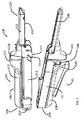
図1〜図11は、本明細書の1つ又は2つ以上の実施例に係る外科用ステープル留め器具100(例えば、本明細書では線形カッタ又はステープラ100とも呼ばれる)を示す。図1に示すように、外科用ステープル留め器具100は、一般に第1のハンドル部分102及び第2のハンドル部分104を備えることができる。様々な実施例では、第1のハンドル部分102及び第2のハンドル部分104は、例えば外科医によって把持されるように構成することができ、ハンドグリップ部分106を備えることができる。一実施例によれば、第1のハンドル部分102は、第1のフレーム110に取り付けられた第1のカバー108を含むことができ、同様に、第2のハンドル部分104は、第2のフレーム114に取り付けられた第2のカバー112を含むことができる。カバー108及び112は、外科医が外科部位内でステープル留め器具100を操作する助けとなるように、人間工学的に造形するか、又は他の方法で適切に造形することができる。様々な実施形態では、ハンドルカバー108及び112は、例えば、拡大突出部109及び113をそれぞれ含むことができ、手術部位へのステープル留め器具100の挿入を容易にすることができる。様々な実施形態では、ハンドルカバー108及び112は、例えばプラスチック、軽量素材、及び/又は任意の他の適切な材料から作製することができるのに対し、ハンドルフレーム110及び114は、例えばステンレス鋼、チタン、及び/又は任意の他の適切な材料から作製することができる。
1 to 11 show a surgical stapler 100 (eg, also referred to herein as a linear cutter or stapler 100) according to one or more embodiments herein. As shown in FIG. 1, the
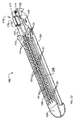
様々な実施例では、ハンドル部分102及び104の遠位端部は、例えば外科部位内の組織を処置するように構成することができるエンドエフェクタ120を備えることができる。少なくとも1つの実施例では、エンドエフェクタ120は、本明細書に記載したように、ステープルカートリッジを受容し及び/又は保持するように構成されたステープルカートリッジチャネル122を含むことができる。実施例によれば、ステープルカートリッジチャネル122は、プラスチック、金属、又は任意の他の適切な材料から作製され得る、第2のハンドル部分フレーム114から延びる一体の細長いチャネル形状のフレームを備えることができる。少なくとも1つの実施例では、ステープルカートリッジチャネル122は、底壁によって接続された一対の対向する細長い側壁を含むことができる。ステープルカートリッジチャネルの後方すなわち近位部分に沿って、一対の離間した、直立した側部フランジが、対向する側壁から上方に延びることができる。様々な実施例では、側部フランジ間のステープルカートリッジチャネル122の幅は、第1のハンドル部分102から延びる下部顎部部材、又はアンビル130の幅よりも大きくなることができる。少なくとも1つの実施形態では、フランジ間の距離は、ステープル留め器具が動作のために組み立てられるとき、アンビル130の少なくとも一部分が側部フランジ間に受容されるのを許容するように構成することができる。1つ又は2つ以上の実施例によれば、各側部フランジは、例えば、ノッチ又は凹部を含むことができ、例えば、アンビル130から延びる1つ若しくは2つ以上のラッチ突起部、及び/又は第1のハンドル部分102の任意の他の適切な部分を受容するように構成することができる。本明細書の1つ又は2つ以上の実施例で使用することができるステープルカートリッジチャネルの実施例(例えば、その中にステープルカートリッジチャネル122として示され説明されているような)は、例えば、2011年6月7日に発行された米国特許第7,954,686号に見出すことができ、その内容は、その全体が参照により本明細書に組み込まれる。
In various embodiments, the distal ends of the
記載したように、ステープルカートリッジチャネル122は、例えば、エンドエフェクタ120内に、ステープルカートリッジ150などのステープルカートリッジを支持及び/又は保持するように構成することができる。実施例では、ステープルカートリッジ150は、その中に取り外し可能に格納された1つ又は2つ以上のステープル(図示せず)を含むことができる。様々な実施例では、図12〜図14を参照すると、ステープルカートリッジ150は、1つ又は2つ以上のステープル空洞151を含むことができ、例えば、横方向に離間した少なくとも2つの長手方向列(例えば、図12に示すような)、又は少なくとも3つの横方向に離間した長手方向列(例えば、図13〜図14に示すような)など、任意の適切な配置で、ステープルを格納するように構成することができる。更に、図12に示すような実施例では、空洞151は、1つ又は2つ以上の組織把持表面部分151aを有することができ、これは、空洞151の1つ又は2つ以上の近位端部又は遠位端部に隣接するか又はそれを囲むなど、空洞151の少なくとも一部分に隣接するか又はそれを囲む組織を把持し、操作するのを助けるために使用される突出部(図示される)、窪み、及び/又は同類のものであることができる。
As described, the
少なくとも1つの実施例では、図13及び図14を参照すると、ステープルカートリッジ150は、ステープルカートリッジ本体152及びパン154を含むことができる。ステープルカートリッジ152は、実施例において、プラスチック又は他の任意の適切な材料から作製することができ、またそれから成形することができ、パン154は、金属、及び/若しくは同類のもの、又は任意の他の可撓性材料から作製することができる。ステープルカートリッジ本体152及び/又はパン154は、その中にステープルスレッド及び/又は切断部材を摺動可能に受容するためのチャネル又は経路を画定するように構成することができる。少なくとも1つの実施例では、パン154は、例えば、可撓性アーム155を含むことができ、それは、スナップ嵌め及び/又はプレス嵌め構成でステープルカートリッジ本体152と係合するように構成することができる。図14〜図17を参照すると、ステープルカートリッジ150は、ステープルスレッド部分162及び/又は切断部材164を含み得るステープルスレッドアセンブリ160(例えば、プラスチック、金属、及び/又は同類のものから作製することができる)を更に含むことができる。様々な例では、スレッド162は、金属、プラスチック、及び/又は同類のものから作製することができ、切断部材164は、金属、又は組織を切断することができる別の材料から作製することができる。更に、実施例では、切断部材164は、例えば、刃先165及びロックアーム166を含むことができ、ロックアーム166は、切断部材164をステープルスレッド部分162に組み立てることができる場合、ステープルスレッド162の開口部163にプレス嵌め及び/又はスナップ嵌めされるように構成することができる。他の様々な実施例では、ステープルスレッドアセンブリ162は切断部材164と一体に成形することができる。
In at least one embodiment, with reference to FIGS. 13 and 14, the
上記に加えて、図12〜図15を参照すると、ステープルカートリッジ本体152は、例えば、スロット156などのスロットを含むことができる。実施例では、スロット156は、その中に切断部材164の少なくとも一部を、及び/又は発射アクチュエータ204によって作動させることができるステープルスレッドアセンブリ160及びプッシャバーアセンブリの任意の他の部分を、受容するように構成することができる。プッシャバーアセンブリ(例えば、プッシーバーアセンブリ200として本明細書に図示され説明されるような)、発射アクチュエータ、及び/又は本明細書の1つ若しくは2つ以上の実施例で使用され得る、ステープルを発射し、組織を切開するために使用され得る他の構成要素の一実施例は、例えば、2011年6月7日に発行された米国特許第7,954,686号に見出すことができ、その内容は、その全体が参照により本明細書に組み込まれる。スロット156は、切断部材164がステープルカートリッジ150内の第1の位置と第2の位置との間で移動することを許容するように構成することができる。様々な実施例では、スロット156は、例えば、ステープルカートリッジ150とアンビル130との間に配置された組織を切開するために、切断部材164が近位位置(図14)と遠位位置との間で移動するのを許容するように構成することができる。
In addition to the above, with reference to FIGS. 12-15, the
図14〜図17などの実施例に示すように、ステープルスレッド部分162は、カム、ランプ、又はアクチュエータ、ステープルカートリッジ150内に配置されたステープルドライバと係合するように構成され得る表面167を含むことができる。様々な実施例では、ステープルカートリッジ150は、スレッド部分162によって、ステープル空洞151内で上方に持ち上げるか、又はスライドさせることができるステープルドライバ168(例えば、プラスチックなどの任意の適切な材料で作製することができる)を含むことができ、そのため、ステープルドライバ168の上方への移動により、アンビル130によってステープル組織に形成され得る、ステープル空洞151内に少なくとも部分的に配置されたステープルを取り出すか又は展開することができる。ステープルドライブ168は、実際には垂直上方に持ち上げることができるが、上方などという用語は、例えば、ステープルドライバ168が、例えば、ステープルカートリッジの上面若しくはデッキ158に向かって、及び/又はアンビル130に向かって、移動できることを指す、意味する、指示する、及び/又は同様のことであることができる。本明細書の実施例では、各ステープルドライバ168は、カム面167と同じ角度で、及び/又は、ステープルスレッド162とステープルドライバ168との間に、比較的平坦な、又は少なくとも実質的に平坦な摺動接触面を提供することができる任意の他の適切な角度で向けられた、1つ又は2つ以上の傾斜面169を含むことができる。様々な実施例では、ステープルドライバは、1つのステープルのみを展開するように構成することができるが、更なる実施例では、ステープルドライバは、例えば、隣接する列に配置された2つ又は3つ以上のステープルを同時に展開するように構成することができる。ステープラ又はカッタ100に含めることができる外科用ステープラ及びその構成要素の更なる実施例は、2008年2月13日に出願された、「SURGICAL STAPLING INSTRUMENT WITH IMPROVED FIRING TRIGGER ARRANGEMENT」と題する米国特許出願第12/030,424号に開示されており、その開示全体が参照により本明細書に組み込まれる。
As shown in examples such as FIGS. 14-17, the
したがって、1つ又は2つ以上の実施例では、本明細書に記載のように、外科用ステープル留め器具は、組織を切開し、かつステープルカートリッジからステープルを展開するように構成された切断部材/ステープルスレッドアセンブリを含むことができる。更なる実施形態では、外科用ステープル留め器具は切断部材を含まない場合がある。少なくとも1つのそのような実施例では、ステープルカートリッジは、その中に配置されたステープルスレッドを含むことができ、及び/又は、外科用器具は、ステープルスレッドをステープルカートリッジに移動させて、例えば、他の方法で組織を切開することなく組織をステープル留めするように構成することができる。他の実施例では、ステープルカートリッジは、その中に配置されたステープルスレッドを含むことができ、その場合、外科用器具は、ステープルカートリッジ内に、又はステープルカートリッジに対して移動可能な切断部材を含むことができる。少なくとも1つのそのような実施例では、切断部材とステープルスレッドとを一緒に前進させることができるように、切断部材を前進させてステープルスレッドと接触させることができる。その後、ステープルカートリッジを外科用器具から取り外し、別の又は新しいステープルスレッドを有する別の又は新しいステープルカートリッジと交換することができるように、切断部材を十分に後退させることができる。そのような実施形態は、ステープルスレッドが使用中に摩耗し得るか又は変形し得る場合に有用となり得る。ステープルカートリッジが、その中に配置された切開部材を含むことができ、外科用器具が、ステープルカートリッジ内へ又はそれに対して移動可能なステープルスレッドを含むことができる場合に、他の実施例を想定することができる。少なくとも1つのそのような実施例では、本明細書に上述した実施例と同様に、切断部材とステープルスレッドとを一緒に前進させることができるように、ステープルスレッドを前進させて切断部材と接触させることができる。その後、ステープルカートリッジを外科用器具から取り外し、別の又は新しい切断部材を有する別の又は新しいステープルスレッドと交換することができるように、ステープルスレッドを十分に後退させることができる。そのような実施例は、切断部材が使用中に摩耗し得るか又は変形し得る場合に有用となり得る。様々な実施例では、ステープルカートリッジは、例えば、外科医又は他の臨床医がステープルカートリッジを取り扱う間に、ステープルカートリッジ内に配置された切断部材に触れるのを防ぐか、又は少なくともその可能性を低減するように構成された保護ハウジング又はカバーを含むことができる。 Thus, in one or more embodiments, as described herein, the surgical staple fastening device is a cutting member configured to incise the tissue and deploy the staples from the staple cartridge /. It can include a staple thread assembly. In a further embodiment, the surgical staple fastener may not include a cutting member. In at least one such embodiment, the staple cartridge may include a staple thread placed therein, and / or the surgical instrument may move the staple thread to the staple cartridge, eg, the other. Can be configured to staple the tissue without incising the tissue in the manner described above. In another embodiment, the staple cartridge may include a staple thread placed therein, in which case the surgical instrument comprises a cutting member that is movable within or with respect to the staple cartridge. be able to. In at least one such embodiment, the cutting member can be advanced and brought into contact with the staple thread so that the cutting member and the staple thread can be advanced together. The cutting member can then be fully retracted so that the staple cartridge can be removed from the surgical instrument and replaced with another or new staple cartridge with another or new staple thread. Such embodiments may be useful if the staple threads can be worn or deformed during use. Other embodiments are envisioned where the staple cartridge can include an incision member placed therein and the surgical instrument can include a staple thread that can move into or relative to the staple cartridge. can do. In at least one such embodiment, the staple thread is advanced and brought into contact with the cutting member so that the cutting member and the staple thread can be advanced together, as in the embodiment described herein. be able to. The staple thread can then be fully retracted so that the staple cartridge can be removed from the surgical instrument and replaced with another or new staple thread with another or new cutting member. Such embodiments may be useful if the cutting member can be worn or deformed during use. In various embodiments, the staple cartridge prevents, for example, the surgeon or other clinician from touching the cutting member placed within the staple cartridge while handling the staple cartridge, or at least reduces the possibility thereof. Protective housings or covers configured as such can be included.
様々な実施形態では、上記に加えて、例えば、ステープルカートリッジチャネル122及び/又はステープルカートリッジ150は、例えば、1つ又は2つ以上の協働する突起部及び/又は凹部を含むことができ、それは、ステープルカートリッジチャネル122内のステープルカートリッジ150を取り外し可能に保持するように構成することができる。様々な実施形態では、ステープルカートリッジ150がステープルカートリッジチャネル122に挿入されると、第1のハンドル部分102を第2のハンドル部分104に組み付けることができる。他の異なる実施形態では、第1のハンドル部分と第2のハンドル部分とを互いに組み付けた後にステープルカートリッジをステープルカートリッジチャネルに挿入することができる。いずれの実施例においても、図1〜図11を参照すると、第1のハンドル部分102及び第2のハンドル部分104は、近位端部103及び105をそれぞれ含むことができ、第1のハンドル部分と第2のハンドル部分とを互いに回転可能又は旋回可能に連結することができるように、互いに組み付けることができる。
In various embodiments, in addition to the above, for example, the
例えば、第2のハンドル部分104は、近位端部105においてそこから延びる1つ又は2つ以上のラッチ、又は突起部111を含むことができる。ラッチ又は突起部111は、金属、プラスチック、及び/又は同類のものから作製することができ、第1のハンドル部102内に金属、プラスチック、及び/又は同類のもので作製することができる1つ又は2つ以上のピン115でラッチされる、又はそれによって受容されるように構成することができる。実施例では、ピン115は、第1のハンドルフレーム110内に画定することができ、ラッチ111は、例えば、第2のハンドルフレーム114の一部であり得るか、又はそれから延び得る、ピン111bなどのピン、ポスト、突出部、及び/又は同類のものから、ラッチ111がそのようなピン、ポスト、突起、及び/又は同類のものを介して回転して、ラッチをピン115の周りに又はその上にスナップ嵌めすることができるように、延びることができる。ラッチ111は、ばね装填する、及び/又は付勢することができる。実施例では、第1のハンドル部分102及び第2のハンドル部分104を組み立てるために、第1及び第2のハンドル部分102、104は、ラッチ111がピン115上で回転してスナップ嵌めされ、それによって受容され得るように、互いにスナップ嵌めすることができる。実施例によれば、ラッチ111は、ラッチ111をピン115から外すか又は離れるように押すために押圧することができるラッチ解除ボタン111aに接続することもでき、それによって、近位端部103、105において、第1及び第2のハンドル部分102、104を互いから取り外すことを可能にする。図示の実施例では、ラッチ解除ボタン111aは、第1及び/又は第2のハンドル部分102、104それぞれに含めることができる。
For example, the
様々な実施例では、アンビル130をステープルカートリッジ150に対して定位置に移動させることができるように、第2のハンドル部分104を第1のハンドル部分102に向けて回転させることができ、及び/又は第1のハンドル部分102を第2のハンドル部分104に向けて回転させることができる。例えば、アンビル130及びステープルカートリッジ150を、図3及び図6に示すように、互いに向けてかつ互いに接近して(例えば、閉位置に)移動させて、それらの間に組織をクランプすることができるように、図1〜図11に示すように、第1のハンドル部分102を第2のハンドル部分104に向けて回転させることができ、及び/又は第1及び第2のハンドル部分102、104を互いに向けて回転させることがでる。第1のハンドル102と第2のハンドル104との間でそのような回転を与えるために、近位端部103、105にそれぞれラッチ111を設けることができる。実施例では、ラッチ111及びピン115は、互いに係合されたとき、その周りに第1及び第2のハンドル部分102、104の一方又は両方を互いに対して移動させることができる旋回軸を備えることができる。様々な実施例では、第2のハンドル部分104を第1のハンドル部分102に対して移動させることができ、それによって、アンビル130をステープルカートリッジ150に対し閉鎖対向した位置(例えば、閉位置)に移動させることができる。実施例では、例えば使用後に第1及び第2のハンドル部分102、104を取り外して、線形カッタ若しくはステープラ100、及び/又は同類のものを再配置するために、外科医又はユーザは、ラッチ解除部111aを押すことができ、それによって近位ラッチ111をピン115から取り外し、第1及び第2のハンドル部分102、104を分離させる。
In various embodiments, the
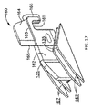
更に、図示の実施例では、第2のハンドル部分104は、第2のハンドルフレーム114から延びるラッチ突起部131を含むことができる。一実施例では、ラッチ突起部131は第2のハンドルフレームに一体的に形成することができる。ラッチ突起部131は、第1のハンドル部分102の一部であり得るリンケージ又は他の突起部(例えば、184)を受容するように構成することができ、それによって、アンビル130及びステープルカートリッジ150を互いにクランプして閉位置にロックすることができる。実施例では、ラッチ突起部131は、ランプ131a及びそれによって形成された凹部又は開口部131bを含む。ランプ131aは、リンケージ又は他の突出部を凹部又は開口部131b内に案内するように構成することができ、それによって、第1及び第2のハウジング部分102、104を閉位置で互いにクランプすることができる。
Further, in the illustrated embodiment, the
図示のように、第1のハンドル部分102は、互いに機械的に接続するか又は互いに機械的に協働することができ、例えば、ラッチ突起部131と係合するように作動させて、第1及び第2のハンドル部分102、104をクランプ又はロックすることができる、クランプアーム180、クランプアームラッチ182、クランプアームスプリング183、オーバーセンターリンク若しくはリンケージ184、及び/又はクランプアーム解除部186を含むことができ、それによって、アンビル130及びステープルカートリッジ150は閉位置にあることができ、本明細書に記載のように、第1及び第2のハンドル部分102、104、アンビル130、並びにステープルカートリッジ150を閉位置から解除することができる。実施例では、クランプアーム180は、プラスチック及び/又は任意の他の適切な材料から作製することができる。例えば、クランプアーム180は、図7に示すように、クランプアーム180を付勢することができるクランプアームラッチ182及びクランプアームスプリング183を介して、開いてロックされるか、又は押圧されないままでいる(例えば、係合解除位置にあるか、又はそのような係合解除位置に留まる)ことができ、それによって、第1及び第2のハンドル部分102、104は、図7及び図10に示すように開位置に留まることができる(例えば、ステープルカートリッジ150及びアンビル130は、使用中の開口部UAなど、それらの間に空間又は開口部を有することができる)。
As shown, the
更に、1つ又は2つ以上の実施例では、線形ステープラ100の第1及び第2のハンドル部分102、104セクションが互いに近位位置にあるとき、クランプアームラッチ182はクランプアーム180を解除することができる。実施例では、クランプアーム180は、クランプアーム180が押圧され得る場合、オーバーセンターリンク又はリンケージ184が図7に示す係合解除位置から図8に示す係合位置に移動することができるように、オーバーセンターリンク又はリンケージ184に接続することができ、またアンビル130及びステープルカートリッジ150が閉位置にあるように、ラッチ突起部131と係合して第1及び第2のハンドル部分102、104をロック又はクランプすることができる。
Further, in one or more embodiments, the
1つ又は2つ以上の実施例によれば、クランプアーム180は、クランプアーム解除部186を介して閉位置からロック解除することができる。例えば、クランプアーム解除部186は、ばね装填式、スライド可能、及び/又は同類のものであることができ、図7、図8に示すように、クランプアーム180の一部分と係合する傾斜表面、ピン、及び/又は同類のものを含むことができる。一実施例では、クランプアーム180を作動させるか又は押圧した後、クランプアーム解除部186は、図7に示す係合解除位置から、図8に示す係合位置(例えば、それは、クランプアーム180及びオーバーセンターリンク又はリンケージ184と係合し得る)に移動することができる。更に、一実施例によれば、クランプアーム解除部186を作動させると(例えば、近位にスライドさせることによって)、クランプアーム180は、図3、図6、図8、及び図11に示す閉じた押圧位置から図1〜図7及び図9、図10に示す開位置に戻ることができる。クランプアーム解除部186は、本明細書に記載のように、図8に示す係合位置から移動して、図7に示す係合解除位置に戻ることもできる。
According to one or more embodiments, the
更に、実施例では、外科用器具100は、その近位のラッチに基づいてその顎部開口部に制限を設けることができる(例えば、本明細書に記載のラッチ111及びピン115によって提供され得る)。例えば、図9に示すように、本明細書に記載のように近位端部103、105をラッチすると、最大顎部開口部MAが外科用器具100によって提供され得る。次いで、第1及び第2のハウジング部分102、104は、本明細書に記載のように、互いに向かって又は互いに対して移動することができ、それによって図10に示すように、使用中の開口部UAが外科用器具100によって提供され得る。使用中の開口部UAは、顎部を閉じて、外科用器具100を閉位置に配置するために、第1及び第2のハウジング部分102、104をクランプすることができるようにそれらを互いに対して移動させた後だが、本明細書に記載のように、クランプアーム180を実際に係合する前の、開口部又は顎部間の距離の範囲とすることができる(例えば、閉位置は、ハンドル部分102、104をクランプアーム180によってロックすることができ、アンビル130及びステープルカートリッジ150が、本明細書に記載のように組織をステープル留めして切開するために互いに近接し得る、位置である)。
Further, in an embodiment, the
したがって、本明細書に記載の実施例では、第1及び第2のハンドル部分102、104の近位端部103、105は、近位ラッチ111などのばね装填ラッチと接続することができ、クランプアーム180は、オーバーセンターリンク又はリンケージ184などのオーバーセンター機構を介してラッチ突起131などのクランプピンと係合することができ、クランプアーム180は、クランプアームスプリング183などのクランプアームスプリング及びクランプアームラッチ182などのクランプアームラッチを介して付勢して開くことができ、クランプアーム解除部186などのスライド可能なラッチとの係合を解除することができる。更に、本明細書の実施例によれば、第1及び第2のハンドル部分102、104は共に、図示及び記載のクランプアーム180及びそれに関連付けられたアセンブリを使用して外科医によって片手でクランプされることができ、これは、外科医が通常両手を使用する、及び/又は外科助手が同様に手助けする現在の線形カッタ又はステープラと逆であり得る。
Therefore, in the embodiments described herein, the proximal ends 103, 105 of the first and
線形カッタ又はステープラ100を作動させるために、1つ又は2つ以上の実施例では(例えば、図2、図3及び図5、図6に示すように)、近位端部103、105における第1及び第2のハンドル部分102、104は、本明細書に記載のように、ラッチ111及びピン115を介して互いに接続することができる。例えば、図1、図2、図4、図5及び図7に示すように、外科医又は線形カッタ又はステープラ100のユーザは、近位端部103、105を互いに近くに配置して、それらを互いに圧縮又は圧搾することができ、それによって、本明細書に記載のように、近位ラッチ111がピン115の周りに旋回してその上にスナップ嵌めされ得る。一実施例では、これにより、第1及び第2のハンドル部分102、104を共に近位端部103、105において、固定してロックするか定又は固定することができる。
In one or more embodiments (eg, as shown in FIGS. 2, 3, 5 and 6), at the proximal ends 103, 105 to activate the linear cutter or
更に、第2のハンドル部分104は、第1のハンドル部分102に対して(例えば、外科医又はユーザによって)及び/又はその逆に移動させることができる。外科医又はユーザは、(例えば、第1及び第2のハンドル部分を図7に示す位置に移動させた後に)クランプアーム180を圧搾又は作動させることができ、それによって、第2のハンドル部分104から延びるラッチ突起部131がオーバーセンターリンク又はリンケージ184を受容することができる。例えば、クランプアーム180を圧搾すると、オーバーセンターリンク又はリンケージ184は、遠位に上方に及び/又はランプ131aに沿って移動することができ、その少なくとも一部分を凹部131b内に受容することができ(例えば、図8に示すように)、それによって、図3、図6、図8及び図11に示すように、アンビル130及びステープルカートリッジ150が閉位置に存在するように、クランプアーム180を係合位置にロックし、第1及び第2のハンドル部分102、104を固定する。様々な実施例では、クランプアーム180を係合位置に圧搾するか又は作動させ、それによって第1及び第2のハウジング部分102、104を共に閉位置にクランプすると(例えば、アンビル130とステープルカートリッジ150とが互いに近接しているか、又は組織上で共にクランプすることができる場合)、次いで、実施例では発射アクチュエータ204を遠位方向に押すことによって、又はそれによって発射アクチュエータ204と係合することによって、線形カッタ又はステープラ100を発射することができる。例えば、アンビル130及びステープルカートリッジ150が十分に配置され、第1及び第2のハウジング位置102、104が閉位置にあると、アンビル130とステープルカートリッジ150との中間に配置された組織は、ステープル留めする及び/又は切開することができる。実施例では、組織をステープル留めする及び/又は切開するために、プッシャバーアセンブリ(例えば、米国特許第7,954,686号に記載のプッシャバーアセンブリ200など)は、例えば、ステープルスレッドアセンブリ160をステープルカートリッジ150内で前進及び/又は後退させるように構成することができる。少なくとも1つの実施例では、プッシャバーアセンブリは、プッシャバー(例えば、米国特許第7,954,686号に記載のプッシャバー202など)、及び発射アクチュエータ204を含むことができ、その場合、発射アクチュエータ204は、本明細書に記載のように、プッシャバー及びステープルスレッドアセンブリ160を遠位に移動させて、ステープルカートリッジ150からステープルを展開し、ステープルをアンビル130に対して変形させるように構成することができる。発射アクチュエータ204は(例えば、プッシャバーを介して)、発射アクチュエータ204を遠位に前進させるか又は他の方法で作動させることができるとき、切断部材164を遠位に移動させて組織を切開するように構成することもできる。例えば、外科医又はユーザは、第1及び第2のハウジング部分102、104の一方の側又は他方の側で発射アクチュエータ204を遠位に移動させることによって発射アクチュエータ204と相互作用することができ、プッシャバー、ステープルスレッドアセンブリ160、及び/又は切断部材164を、遠位に移動させるか又は前進させ、それによってステープルを組織内に展開し、及び/又は組織を切開する。
Further, the
実施例では、組織を切開及び/又はステープル留めした後、実施例では、発射アクチュエータ204は、プッシャバー、ステープルスレッドアセンブリ160、及び/又は切断部材164を近位に移動させ、それによってステープル留め及び/又は切断手順を完了するように構成することができる。例えば、外科医又はユーザは、発射アクチュエータ204を近位にその発射前位置に戻すように移動させて、プッシャバー、スレッドアセンブリ160、及び切断部材164を後退させることができる。そのような構成要素を後退させるか、近位に発射前位置に戻すように移動させる(例えば、図3に示すように)と、ステープル留め器具100(例えば、線形カッタ又はステープラ100)を開いて、別のカートリッジをステープルに追加し、及び/又は追加の組織を切開し、及び/又は実行される手順を終了した後に器具を取り外すことができる。例えば、外科医は、発射アクチュエータ204をその発射前位置に戻すように移動させ、それによって、プッシャバー、ステープルスレッド、切断部、及び/又は同類のものを後退させることができる。実施例では、外科医は、次いで、クランプアーム解除部186と相互作用するか又はそれを作動させる(例えば、近位にスライドさせることによって)ことができ、それにより、オーバーセンターリンク又はリンケージ184を凹部131bから移動させ、かつ、ランプ131aの近位下方に及び/又はそれに沿って、図8に示す係合位置から図7に示す係合解除位置に戻るように移動させる。クランプアーム180は、図8並びに図3及び図6に示す閉じた押圧位置から、図7並びに図1、図2及び図4〜図6に示す開位置に戻ることもできる。実施例によれば、外科医は、ラッチ解除ボタン111aを押すことによってラッチ解除ボタン111aと相互作用することもでき、それによってラッチ111をピン115から外すか又は離れるように押し、それによって第1及び第2のハンドル部分102、104を近位端部103、105において互いに取り外して、図1及び図3に示す位置に戻すことを可能にする。
In the embodiment, after the tissue is incised and / or stapled, in the embodiment, the
以下の実施例は、本明細書の教示を組み合わせるか又は適用することができる、種々の非網羅的な方法に関する。以下の実施例は、本出願における又は本出願の後の出願におけるどの時点でも提示され得る、いずれの請求項の適用範囲をも限定することを目的としたものではない、と理解されたい。いかなる棄権をも意図するものではない。以下の実施例は、単なる例示の目的で与えられるものにすぎない。本明細書の種々の教示は、他の多くの方法で構成及び適用が可能であると考えられている。また、いくつかの変形形態では、以下の実施例において言及される特定の特徴を省略してよいことも、考えられる。したがって、本発明者又は本発明者の利益の継承者により、後日、そうである旨が明示的に示されない限り、以下に言及される態様又は特徴のいずれも重要なものとして見なされるべきではない。以下に言及される特徴以外の更なる特徴を含む請求項が本出願において、又は本出願に関連する後の出願において示される場合、これらの更なる特徴は、特許性に関連するいずれかの理由により追加されたものとしても、仮定されるべきではない。 The following examples relate to various non-exhaustive methods to which the teachings herein can be combined or applied. It should be understood that the following examples are not intended to limit the scope of any claim that may be presented at any time in this application or in subsequent applications. No intention of abstention is intended. The following examples are given for purposes of illustration only. It is believed that the various teachings herein can be constructed and applied in many other ways. It is also conceivable that in some variants, certain features referred to in the following examples may be omitted. Therefore, any of the embodiments or features referred to below should not be considered significant unless explicitly indicated at a later date by the inventor or the successor to the interests of the inventor. .. Where a claim containing additional features other than those referred to below is presented in this application or in a later application related to this application, these additional features are any reason related to patentability. Should not be assumed, even if added by.
実施例1:外科用器具は、第1及び第2のハンドル部分を備えるハンドルを備えることができ、第1及び第2のハウジング部分の一方は、近位ラッチ及び近位ラッチピンを備え、近位ラッチ及び近位ラッチピンは、第1及び第2のハウジング部分をそれらの近位端部で互いにロックするように構成されており、第1及び第2のハウジング部分の一方は、ラッチ突出部、クランプアーム、オーバーセンターリンケージを更に備え、ラッチ突出部及びオーバーセンターリンケージは、クランプアームが係合されているか又は係合位置にあるときに、外科用器具を閉位置にロックするように構成されている。 Example 1: A surgical instrument can be provided with a handle comprising first and second handle portions, one of the first and second housing portions comprising a proximal latch and a proximal latch pin, proximal. The latch and the proximal latch pin are configured to lock the first and second housing portions to each other at their proximal ends, with one of the first and second housing portions being the latch overhang, the clamp. Further provided with an arm, overcenter linkage, the latch protrusion and overcenter linkage are configured to lock the surgical instrument to the closed position when the clamp arm is engaged or in the engaged position. ..
実施例2:外科用器具の第1及び第2のハウジング部分の一方は、近位ラッチ解除部を備えることができ、近位ラッチ解除部は、第1及び第2のハウジングを、互いにロックされた後にそれらの近位端部で解除するか又は取り外すように構成されている。 Example 2: One of the first and second housing portions of the surgical instrument can be provided with a proximal latch release portion, the proximal latch release portion locking the first and second housings to each other. It is configured to be released or removed at their proximal end afterwards.
実施例3:外科用器具の第1及び第2のハウジング部分の一方は、クランプアーム解除部を備えることができ、クランプアーム解除部は、クランプアームが係合されているときに外科用器具を閉位置からロック解除するように構成されている。 Example 3: One of the first and second housing portions of the surgical instrument can be provided with a clamp arm release portion, which provides the surgical instrument when the clamp arm is engaged. It is configured to unlock from the closed position.
実施例4:外科用器具の第1及び第2のハウジング部分の一方は、クランプアームラッチ及びクランプアームスプリングを備えることができ、クランプアームラッチ及びクランプアームスプリングは、クランプアームを係合解除位置に付勢するように構成されている。 Example 4: One of the first and second housing portions of the surgical instrument can be provided with a clamp arm latch and a clamp arm spring, the clamp arm latch and the clamp arm spring in a clamp arm disengagement position. It is configured to be urged.
実施例5:外科用器具の第1及び第2のハンドル部分の一方は、それぞれ、第1及び第2のフレームを備えることができる。 Example 5: One of the first and second handle portions of the surgical instrument can comprise a first and second frame, respectively.
実施例6:外科用器具の第1及び第2のフレームの一方は、そこから延びるステープルチャネルを備えることができる。 Example 6: One of the first and second frames of the surgical instrument can be provided with staple channels extending from it.
実施例7:外科用器具のステープルチャネルは、その中にステープルカートリッジを受容するように構成することができる。 Example 7: The staple channel of a surgical instrument can be configured to receive a staple cartridge therein.
実施例8:外科用器具の第1及び第2のフレームの一方は、そこから延びるアンビルを備えることができる。 Example 8: One of the first and second frames of the surgical instrument can comprise an anvil extending from it.
実施例9:外科用器具は、プッシャアセンブリ、切断部材、及び発射アクチュエータのうちの1つ又は2つ以上を備えることができる。 Example 9: The surgical instrument can include one or more of a pusher assembly, a cutting member, and a firing actuator.
実施例10:外科用器具の発射アクチュエータは、プッシャアセンブリ及び切断部材を近位位置から遠位位置に移動させて、組織を切開し、クランプアームが係合され得るか又は係合位置にあり得るときにアンビルを介して組織内にステープルが形成され得るように、ステープルカートリッジからステープルを展開するように構成することができる。 Example 10: The firing actuator of the surgical instrument moves the pusher assembly and cutting member from the proximal position to the distal position to incise the tissue and the clamp arm may or may be in the engaged position. Staples can be configured to be unfolded from the staple cartridge so that staples can sometimes be formed within the tissue through the anvil.
本明細書に記載される器具の変形形態のいずれも、上述されるものに加えて、又はそれらの代わりに、種々のその他の特徴を含んでもよい、と理解されたい。あくまで一例として、本明細書に記載される器具のいずれもが、本明細書に参考として組み込まれる種々の参考文献のいずれかにおいて開示される種々の特徴のうちの、1つ又は2つ以上を含むことができる。また、多数の方法にて、本明細書の引用文献のいずれかの教示と本明細書の教示とを容易に組み合わせ得るように、本明細書の教示は、本明細書のその他の引用文献のいずれかに記載される器具のいずれにも容易に適用され得る、とも理解されたい。更に、当業者であれば、本明細書の種々の教示が、電気外科器具、ステープル留め器具、及び他の種類の外科器具に容易に適用され得ることを認識するであろう。本明細書の教示が組み込まれ得るその他の種類の器具が、当業者に明らかであろう。 It should be appreciated that any of the variants of the instruments described herein may include various other features in addition to or in place of those described above. As an example only, any of the instruments described herein shall have one or more of the various features disclosed in any of the various references incorporated herein by reference. Can include. Also, the teachings of the present specification are in reference to the other references of the present specification so that the teachings of any of the references herein can be easily combined with the teachings of the present specification in a number of ways. It should also be understood that it can be easily applied to any of the instruments described in either. Moreover, one of ordinary skill in the art will recognize that the various teachings herein can be readily applied to electrosurgical instruments, stapled instruments, and other types of surgical instruments. Other types of instruments to which the teachings herein may be incorporated will be apparent to those of skill in the art.
本明細書に参考として組み込まれると言及されたいかなる特許、公報、又は他の開示内容も、全体的に又は部分的に、組み込まれた内容が現行の定義、見解、又は本明細書に記載される他の開示内容とあくまで矛盾しない範囲でのみ本明細書に組み込まれる、と理解されなければならない。そのようなものであるから、また必要な範囲で、本明細書に明瞭に記載される開示内容は、参考として本明細書に組み込まれているあらゆる矛盾する記載に優先するものとする。現行の定義、見解、又は本明細書に記載される他の開示内容と矛盾する任意の内容、又はそれらの部分は本明細書に参考として組み込まれるものとするが、参照内容と現行の開示内容との間に矛盾が生じない範囲においてのみ、参照されるものとする。 Any patent, gazette, or other disclosure that is referred to herein as a reference, in whole or in part, is described in the current definition, opinion, or specification. It should be understood that it is incorporated herein only to the extent that it does not conflict with any other disclosure. As such, and to the extent necessary, the disclosures expressly set forth herein shall supersede any contradictory statements incorporated herein for reference. Any content that conflicts with current definitions, views, or other disclosures described herein, or parts thereof, shall be incorporated herein by reference, but with reference and current disclosure. It shall be referred to only to the extent that there is no contradiction with.
上記のデバイスの変形形態は、医療専門家により行われる従来の治療及び処置における用途のみではなく、ロボット支援された治療及び処置における用途をも有してよい。あくまで一例として、本明細書の種々の教示は、ロボット外科用システム、例えばIntuitive Surgical,Inc.(Sunnyvale,California)によるDAVINCI(商標)システムなどに容易に組み込まれてよい。同様に、本明細書の種々の教示は、その開示が本明細書に参考として組み込まれる、米国特許第6,783,524号、名称「Robotic Surgical Tool with Ultrasound Cauterizing and Cutting Instrument」(2004年8月31日公開)の種々の教示と容易に組み合わされ得ることを、当業者であれば理解するであろう。 The variants of the device may have applications in robot-assisted therapies and procedures as well as in conventional therapies and procedures performed by medical professionals. As an example, the various teachings herein refer to robotic surgical systems such as Intuitive Surgical, Inc. It may be easily incorporated into a DAVINCI ™ system by (Sunnyvale, California). Similarly, the various teachings herein are incorporated herein by reference in US Pat. No. 6,783,524, entitled "Robotical Surgical Tool with Ultrasound Cauterizing and Cutting Instrument" (2004 8). Those skilled in the art will appreciate that it can be easily combined with the various teachings (published on 31st May).
上記の変形形態は、1回の使用後に廃棄されるように設計されてもよく、又はそれらは複数回使用されるように設計されてもよい。変形形態は、一方又はその両方の場合において、少なくとも1回の使用後に再利用のために再調整されてよい。再調整は、デバイスの分解工程、それに続く特定の部分の洗浄又は交換工程、及びその後の再組み立て工程の、任意の組み合わせを含んでよい。特に、デバイスのいくつかの変形形態は、分解することができ、デバイスの任意の数の特定の部分若しくは部品を、任意の組み合わせにおいて選択的に交換又は取り外してもよい。特定の部品の洗浄及び/又は交換後、デバイスのいくつかの変形形態を、再調整用の施設において、又は処置の直前に使用者によってのいずれかで、その後の使用のために再組み立てすることができる。当業者であれば、デバイスの再調整において、分解、洗浄/交換、及び再組み立てのための種々の技術を利用することができることを、理解するであろう。このような技術の使用、及び結果として得られる再調整されたデバイスは、すべて本出願の範囲内にある。 The above variants may be designed to be discarded after a single use, or they may be designed to be used multiple times. The variants may be readjusted for reuse after at least one use in one or both cases. The readjustment may include any combination of a device disassembly step, followed by a cleaning or replacement step of a particular portion, and a subsequent reassembly step. In particular, some variants of the device can be disassembled and any number of specific parts or parts of the device may be selectively replaced or removed in any combination. After cleaning and / or replacing certain parts, reassembling some variants of the device, either in a readjustment facility or by the user shortly before treatment, for subsequent use. Can be done. Those skilled in the art will appreciate that various techniques for disassembly, cleaning / replacement, and reassembly can be utilized in the readjustment of the device. The use of such techniques and the resulting readjusted devices are all within the scope of this application.
あくまで一例として、本明細書に記載される変形形態は、処置の前及び/又は後に滅菌されてもよい。1つの滅菌技術では、デバイスをプラスチック製又はTYVEK製のバックなどの閉鎖及び密封された容器に入れる。次いで、容器及びデバイスを、γ線、X線、又は高エネルギー電子線などの、容器を透過し得る放射線場に置いてよい。放射線は、デバイス上及び容器内の細菌を死滅させ得る。次に、滅菌されたデバイスを、後の使用のために、滅菌容器中に保管してよい。β線若しくはγ線、エチレンオキシド、又は水蒸気が挙げられるがこれらに限定されない、当該技術分野で周知の他の任意の技術を用いて、デバイスを滅菌してもよい。 As an example, the variants described herein may be sterilized before and / or after treatment. In one sterilization technique, the device is placed in a closed and sealed container such as a plastic or TYVEK bag. The vessel and device may then be placed in a radiation field capable of penetrating the vessel, such as gamma rays, X-rays, or high energy electron beams. Radiation can kill bacteria on the device and in the container. The sterilized device may then be stored in a sterilized container for later use. The device may be sterilized using any other technique well known in the art, including but not limited to beta or gamma rays, ethylene oxide, or water vapor.
以上、本発明の種々の実施形態を図示及び説明したが、本発明の範囲から逸脱することなく、当業者による適切な改変により、本明細書に記載される方法及びシステムの更なる適合化を実現することができる。このような可能な改変のうちのいくつかについて述べたが、他の改変も当業者には明らかであろう。例えば、上記の実施例、実施形態、形状、材料、寸法、比率、工程などは例示的なものであって、必須のものではない。したがって、本発明の範囲は、以下の特許請求の範囲の観点から考慮されるべきものであり、本明細書及び図面において図示され、説明された構造及び動作の細部に限定されないものとして、理解されたい。 Although various embodiments of the present invention have been illustrated and described above, further adaptation of the methods and systems described herein can be made by appropriate modification by those skilled in the art without departing from the scope of the present invention. It can be realized. Some of these possible modifications have been mentioned, but others will be apparent to those of skill in the art. For example, the above examples, embodiments, shapes, materials, dimensions, ratios, processes, etc. are exemplary and not essential. Accordingly, the scope of the invention should be considered in the light of the following claims and is understood to be not limited to the structural and operational details illustrated and described herein and in the drawings. sea bream.
〔実施の態様〕
(1) 外科用器具であって、
第1及び第2のハンドル部分を備えるハンドルを備え、第1及び第2のハウジング部分の一方は、近位ラッチ及び近位ラッチピンを備え、前記近位ラッチ及び前記近位ラッチピンは、前記第1及び第2のハウジング部分をそれらの近位端部で互いにロックするように構成されており、前記第1及び第2のハウジング部分の一方は、ラッチ突出部、クランプアーム、オーバーセンターリンケージを更に備え、前記ラッチ突出部及び前記オーバーセンターリンケージは、前記クランプアームが係合されているか又は係合位置にあるときに、前記外科用器具を閉位置にロックするように構成されている、外科用器具。
(2) 前記第1及び第2のハウジング部分の一方は、近位ラッチ解除部を更に備え、前記近位ラッチ解除部は、前記第1及び第2のハウジングを、互いにロックされた後にそれらの近位端部で解除するか又は取り外すように構成されている、実施態様1に記載の外科用器具。
(3) 前記第1及び第2のハウジング部分の一方は、クランプアーム解除部を更に備え、前記クランプアーム解除部は、前記クランプアームが係合されているときに前記外科用器具を前記閉位置からロック解除するように構成されている、実施態様1に記載の外科用器具。
(4) 前記第1及び第2のハウジング部分の一方は、クランプアームラッチ及びクランプアームスプリングを更に備え、前記クランプアームラッチ及びクランプアームスプリングは、前記クランプアームを係合解除位置に付勢するように構成されている、実施態様1に記載の外科用器具。
(5) 前記第1及び第2のハンドル部分は、それぞれ、第1及び第2のフレームを更に備える、実施態様1に記載の外科用器具。
[Implementation mode]
(1) It is a surgical instrument and
A handle with first and second handle portions is provided, one of the first and second housing portions comprises a proximal latch and a proximal latch pin, and the proximal latch and the proximal latch pin are said to be the first. And the second housing portions are configured to lock each other at their proximal ends, one of the first and second housing portions further comprising a latch overhang, a clamp arm and an overcenter linkage. , The latch protrusion and the overcenter linkage are configured to lock the surgical instrument to a closed position when the clamp arm is engaged or in an engaged position. ..
(2) One of the first and second housing portions further comprises a proximal latch release portion, wherein the proximal latch release portion thereof locks the first and second housings to each other. The surgical instrument according to embodiment 1, which is configured to be released or removed at the proximal end.
(3) One of the first and second housing portions further includes a clamp arm release portion, and the clamp arm release portion holds the surgical instrument in the closed position when the clamp arm is engaged. The surgical instrument according to embodiment 1, which is configured to be unlocked from.
(4) One of the first and second housing portions further includes a clamp arm latch and a clamp arm spring, and the clamp arm latch and the clamp arm spring urge the clamp arm to the disengagement position. The surgical instrument according to embodiment 1, which is configured in 1.
(5) The surgical instrument according to embodiment 1, wherein the first and second handle portions further include a first and second frame, respectively.
(6) 前記第1及び第2のフレームの一方は、そこから延びるステープルチャネルを備える、実施態様5に記載の外科用器具。
(7) 前記ステープルチャネルは、その中にステープルカートリッジを受容するように構成されている、実施態様6に記載の外科用器具。
(8) 前記第1及び第2のフレームの一方は、そこから延びるアンビルを備える、実施態様6に記載の外科用器具。
(9) プッシャアセンブリ、切断部材、及び発射アクチュエータのうちの1つ又は2つ以上を更に備える、実施態様8に記載の外科用器具。
(10) 前記発射アクチュエータは、前記プッシャアセンブリ及び前記切断部材を近位位置から遠位位置に移動させて、組織を切開し、前記クランプアームが係合されているか又は前記係合位置にあるときに前記アンビルを介して前記組織内にステープルが形成され得るように、前記ステープルカートリッジからステープルを展開するように構成されている、実施態様9に記載の外科用器具。
(6) The surgical instrument according to embodiment 5, wherein one of the first and second frames comprises a staple channel extending from the first and second frames.
(7) The surgical instrument according to embodiment 6, wherein the staple channel is configured to receive a staple cartridge therein.
(8) The surgical instrument according to embodiment 6, wherein one of the first and second frames comprises an anvil extending from the first and second frames.
(9) The surgical instrument according to embodiment 8, further comprising one or more of a pusher assembly, a cutting member, and a firing actuator.
(10) When the firing actuator moves the pusher assembly and the cutting member from a proximal position to a distal position to incise the tissue and the clamp arm is engaged or in the engaged position. 9. The surgical instrument according to embodiment 9, which is configured to deploy staples from the staple cartridge so that staples can be formed in the tissue via the anvil.
Claims (9)
第1及び第2のハンドル部分を備えるハンドルを備え、前記第1及び第2のハンドル部分の一方は、近位ラッチを備え、前記第1及び第2のハンドル部分の他方は、近位ラッチピンを備え、前記近位ラッチ及び前記近位ラッチピンは、前記第1及び第2のハンドル部分をそれらの近位端部で互いにロックするように構成されており、
前記第2のハンドル部分は、第2のフレーム、及び、前記第2のフレームから延びるラッチ突出部を備え、前記第1のハンドル部分は、第1のフレーム、前記第1のフレームに連結された付勢部材、前記付勢部材を介して前記第1のフレームに対して移動可能に連結されたクランプアーム、及び、オーバーセンターリンケージを備え、
前記ラッチ突出部は、ランプ、及び、前記ランプによって形成された凹部または開口部を含み、
前記オーバーセンターリンケージの一端は、前記クランプアームに回動可能に連結され、前記オーバーセンターリンケージの他端は、前記第1のフレームに形成された長孔内にスライド可能に連結され、
前記クランプアームが押されて、前記第1のハンドル部分が、前記第1及び第2のハンドル部分が互いに開いている開位置から、前記第1及び第2のハンドル部分が互いに閉じている閉位置に移動する際に、前記クランプアームと共に前記第1のフレームが移動し、前記オーバーセンターリンケージの前記他端が、遠位に上方に移動して、前記ラッチ突出部の前記ランプに案内されて、前記ラッチ突出部の前記凹部または開口部内に到達し、前記第1及び第2のハンドル部分が互いに近接した位置にある際に、前記付勢部材による前記クランプアームの付勢を解除して、前記クランプアームを押すことで、前記クランプアームが前記第1のフレームに対して移動し、前記オーバーセンターリンケージの他端が、前記第1のフレームに形成された前記長孔内をスライドして、これにより、前記オーバーセンターリンケージの前記他端は、前記オーバーセンターリンケージと前記ラッチ突出部との非係合位置から前記オーバーセンターリンケージと前記ラッチ突出部との係合位置に移動し、前記ラッチ突出部及び前記オーバーセンターリンケージは、前記第1のハンドル部分を前記閉位置にロックする、外科用器具。 It ’s a surgical instrument,
It comprises a handle with first and second handle portions, one of the first and second handle portions comprising a proximal latch and the other of the first and second handle portions having a proximal latch pin. The proximal latch and the proximal latch pin are configured to lock the first and second handle portions to each other at their proximal ends.
The second handle portion includes a second frame and a latch protrusion extending from the second frame, and the first handle portion is connected to the first frame and the first frame. It comprises an urging member, a clamp arm movably connected to the first frame via the urging member, and an overcenter linkage .
The latch protrusion comprises a lamp and a recess or opening formed by the lamp.
One end of the overcenter linkage is rotatably connected to the clamp arm, and the other end of the overcenter linkage is slidably connected into an elongated hole formed in the first frame.
When the clamp arm is pushed, the first handle portion is in an open position in which the first and second handle portions are open to each other, and the first and second handle portions are in a closed position in which the first and second handle portions are closed to each other. When moving to, the first frame moves with the clamp arm, and the other end of the overcenter linkage moves distally upward and is guided by the ramp of the latch protrusion. When the first and second handle portions reach the inside of the recess or opening of the latch protrusion and the first and second handle portions are in close proximity to each other, the clamp arm is released from the urging by the urging member. By pushing the clamp arm, the clamp arm moves with respect to the first frame, and the other end of the overcenter linkage slides in the elongated hole formed in the first frame. As a result, the other end of the overcenter linkage moves from the non-engagement position between the overcenter linkage and the latch protrusion to the engagement position between the overcenter linkage and the latch protrusion, and the latch protrusion and the over-center linkage for locking the first handle portion to said closed position, a surgical instrument.
Applications Claiming Priority (5)
| Application Number | Priority Date | Filing Date | Title |
|---|---|---|---|
| US201662380746P | 2016-08-29 | 2016-08-29 | |
| US62/380,746 | 2016-08-29 | ||
| US15/679,194 US10682137B2 (en) | 2016-08-29 | 2017-08-17 | Surgical stapler |
| US15/679,194 | 2017-08-17 | ||
| PCT/US2017/048341 WO2018044669A1 (en) | 2016-08-29 | 2017-08-24 | Surgical stapler |
Publications (2)
| Publication Number | Publication Date |
|---|---|
| JP2019524417A JP2019524417A (en) | 2019-09-05 |
| JP6983889B2 true JP6983889B2 (en) | 2021-12-17 |
Family
ID=59846636
Family Applications (1)
| Application Number | Title | Priority Date | Filing Date |
|---|---|---|---|
| JP2019531542A Active JP6983889B2 (en) | 2016-08-29 | 2017-08-24 | Surgical stapler |
Country Status (7)
| Country | Link |
|---|---|
| US (1) | US10682137B2 (en) |
| EP (1) | EP3289985B1 (en) |
| JP (1) | JP6983889B2 (en) |
| CN (1) | CN109661201B (en) |
| MX (1) | MX2019002379A (en) |
| PL (1) | PL3289985T3 (en) |
| WO (1) | WO2018044669A1 (en) |
Families Citing this family (225)
| Publication number | Priority date | Publication date | Assignee | Title |
|---|---|---|---|---|
| US20070084897A1 (en) | 2003-05-20 | 2007-04-19 | Shelton Frederick E Iv | Articulating surgical stapling instrument incorporating a two-piece e-beam firing mechanism |
| US9060770B2 (en) | 2003-05-20 | 2015-06-23 | Ethicon Endo-Surgery, Inc. | Robotically-driven surgical instrument with E-beam driver |
| US11896225B2 (en) | 2004-07-28 | 2024-02-13 | Cilag Gmbh International | Staple cartridge comprising a pan |
| US7669746B2 (en) | 2005-08-31 | 2010-03-02 | Ethicon Endo-Surgery, Inc. | Staple cartridges for forming staples having differing formed staple heights |
| US11246590B2 (en) | 2005-08-31 | 2022-02-15 | Cilag Gmbh International | Staple cartridge including staple drivers having different unfired heights |
| US7934630B2 (en) | 2005-08-31 | 2011-05-03 | Ethicon Endo-Surgery, Inc. | Staple cartridges for forming staples having differing formed staple heights |
| US10159482B2 (en) | 2005-08-31 | 2018-12-25 | Ethicon Llc | Fastener cartridge assembly comprising a fixed anvil and different staple heights |
| US11484312B2 (en) | 2005-08-31 | 2022-11-01 | Cilag Gmbh International | Staple cartridge comprising a staple driver arrangement |
| US20070106317A1 (en) | 2005-11-09 | 2007-05-10 | Shelton Frederick E Iv | Hydraulically and electrically actuated articulation joints for surgical instruments |
| US8820603B2 (en) | 2006-01-31 | 2014-09-02 | Ethicon Endo-Surgery, Inc. | Accessing data stored in a memory of a surgical instrument |
| US20120292367A1 (en) | 2006-01-31 | 2012-11-22 | Ethicon Endo-Surgery, Inc. | Robotically-controlled end effector |
| US8708213B2 (en) | 2006-01-31 | 2014-04-29 | Ethicon Endo-Surgery, Inc. | Surgical instrument having a feedback system |
| US11793518B2 (en) | 2006-01-31 | 2023-10-24 | Cilag Gmbh International | Powered surgical instruments with firing system lockout arrangements |
| US8186555B2 (en) | 2006-01-31 | 2012-05-29 | Ethicon Endo-Surgery, Inc. | Motor-driven surgical cutting and fastening instrument with mechanical closure system |
| US7845537B2 (en) | 2006-01-31 | 2010-12-07 | Ethicon Endo-Surgery, Inc. | Surgical instrument having recording capabilities |
| US20110290856A1 (en) | 2006-01-31 | 2011-12-01 | Ethicon Endo-Surgery, Inc. | Robotically-controlled surgical instrument with force-feedback capabilities |
| US8992422B2 (en) | 2006-03-23 | 2015-03-31 | Ethicon Endo-Surgery, Inc. | Robotically-controlled endoscopic accessory channel |
| US10568652B2 (en) | 2006-09-29 | 2020-02-25 | Ethicon Llc | Surgical staples having attached drivers of different heights and stapling instruments for deploying the same |
| US8684253B2 (en) | 2007-01-10 | 2014-04-01 | Ethicon Endo-Surgery, Inc. | Surgical instrument with wireless communication between a control unit of a robotic system and remote sensor |
| US20080169332A1 (en) | 2007-01-11 | 2008-07-17 | Shelton Frederick E | Surgical stapling device with a curved cutting member |
| US8931682B2 (en) | 2007-06-04 | 2015-01-13 | Ethicon Endo-Surgery, Inc. | Robotically-controlled shaft based rotary drive systems for surgical instruments |
| US11672531B2 (en) | 2007-06-04 | 2023-06-13 | Cilag Gmbh International | Rotary drive systems for surgical instruments |
| US11849941B2 (en) | 2007-06-29 | 2023-12-26 | Cilag Gmbh International | Staple cartridge having staple cavities extending at a transverse angle relative to a longitudinal cartridge axis |
| BRPI0901282A2 (en) | 2008-02-14 | 2009-11-17 | Ethicon Endo Surgery Inc | surgical cutting and fixation instrument with rf electrodes |
| US7819298B2 (en) | 2008-02-14 | 2010-10-26 | Ethicon Endo-Surgery, Inc. | Surgical stapling apparatus with control features operable with one hand |
| US9179912B2 (en) | 2008-02-14 | 2015-11-10 | Ethicon Endo-Surgery, Inc. | Robotically-controlled motorized surgical cutting and fastening instrument |
| US7866527B2 (en) | 2008-02-14 | 2011-01-11 | Ethicon Endo-Surgery, Inc. | Surgical stapling apparatus with interlockable firing system |
| US8636736B2 (en) | 2008-02-14 | 2014-01-28 | Ethicon Endo-Surgery, Inc. | Motorized surgical cutting and fastening instrument |
| US9386983B2 (en) | 2008-09-23 | 2016-07-12 | Ethicon Endo-Surgery, Llc | Robotically-controlled motorized surgical instrument |
| US11648005B2 (en) | 2008-09-23 | 2023-05-16 | Cilag Gmbh International | Robotically-controlled motorized surgical instrument with an end effector |
| US8210411B2 (en) | 2008-09-23 | 2012-07-03 | Ethicon Endo-Surgery, Inc. | Motor-driven surgical cutting instrument |
| US9005230B2 (en) | 2008-09-23 | 2015-04-14 | Ethicon Endo-Surgery, Inc. | Motorized surgical instrument |
| US8608045B2 (en) | 2008-10-10 | 2013-12-17 | Ethicon Endo-Sugery, Inc. | Powered surgical cutting and stapling apparatus with manually retractable firing system |
| US11849952B2 (en) | 2010-09-30 | 2023-12-26 | Cilag Gmbh International | Staple cartridge comprising staples positioned within a compressible portion thereof |
| US11812965B2 (en) | 2010-09-30 | 2023-11-14 | Cilag Gmbh International | Layer of material for a surgical end effector |
| US9629814B2 (en) | 2010-09-30 | 2017-04-25 | Ethicon Endo-Surgery, Llc | Tissue thickness compensator configured to redistribute compressive forces |
| US9272406B2 (en) | 2010-09-30 | 2016-03-01 | Ethicon Endo-Surgery, Llc | Fastener cartridge comprising a cutting member for releasing a tissue thickness compensator |
| US9320523B2 (en) | 2012-03-28 | 2016-04-26 | Ethicon Endo-Surgery, Llc | Tissue thickness compensator comprising tissue ingrowth features |
| US10945731B2 (en) | 2010-09-30 | 2021-03-16 | Ethicon Llc | Tissue thickness compensator comprising controlled release and expansion |
| US8657176B2 (en) | 2010-09-30 | 2014-02-25 | Ethicon Endo-Surgery, Inc. | Tissue thickness compensator for a surgical stapler |
| US9211120B2 (en) | 2011-04-29 | 2015-12-15 | Ethicon Endo-Surgery, Inc. | Tissue thickness compensator comprising a plurality of medicaments |
| US8695866B2 (en) | 2010-10-01 | 2014-04-15 | Ethicon Endo-Surgery, Inc. | Surgical instrument having a power control circuit |
| CA2834649C (en) | 2011-04-29 | 2021-02-16 | Ethicon Endo-Surgery, Inc. | Staple cartridge comprising staples positioned within a compressible portion thereof |
| US9072535B2 (en) | 2011-05-27 | 2015-07-07 | Ethicon Endo-Surgery, Inc. | Surgical stapling instruments with rotatable staple deployment arrangements |
| MX350846B (en) | 2012-03-28 | 2017-09-22 | Ethicon Endo Surgery Inc | Tissue thickness compensator comprising capsules defining a low pressure environment. |
| BR112014024102B1 (en) | 2012-03-28 | 2022-03-03 | Ethicon Endo-Surgery, Inc | CLAMP CARTRIDGE ASSEMBLY FOR A SURGICAL INSTRUMENT AND END ACTUATOR ASSEMBLY FOR A SURGICAL INSTRUMENT |
| US9101358B2 (en) | 2012-06-15 | 2015-08-11 | Ethicon Endo-Surgery, Inc. | Articulatable surgical instrument comprising a firing drive |
| US20140001231A1 (en) | 2012-06-28 | 2014-01-02 | Ethicon Endo-Surgery, Inc. | Firing system lockout arrangements for surgical instruments |
| US9289256B2 (en) | 2012-06-28 | 2016-03-22 | Ethicon Endo-Surgery, Llc | Surgical end effectors having angled tissue-contacting surfaces |
| US9226751B2 (en) | 2012-06-28 | 2016-01-05 | Ethicon Endo-Surgery, Inc. | Surgical instrument system including replaceable end effectors |
| US9649111B2 (en) | 2012-06-28 | 2017-05-16 | Ethicon Endo-Surgery, Llc | Replaceable clip cartridge for a clip applier |
| BR112014032776B1 (en) | 2012-06-28 | 2021-09-08 | Ethicon Endo-Surgery, Inc | SURGICAL INSTRUMENT SYSTEM AND SURGICAL KIT FOR USE WITH A SURGICAL INSTRUMENT SYSTEM |
| BR112015021098B1 (en) | 2013-03-01 | 2022-02-15 | Ethicon Endo-Surgery, Inc | COVERAGE FOR A JOINT JOINT AND SURGICAL INSTRUMENT |
| US10405857B2 (en) | 2013-04-16 | 2019-09-10 | Ethicon Llc | Powered linear surgical stapler |
| BR112015026109B1 (en) | 2013-04-16 | 2022-02-22 | Ethicon Endo-Surgery, Inc | surgical instrument |
| US9510828B2 (en) | 2013-08-23 | 2016-12-06 | Ethicon Endo-Surgery, Llc | Conductor arrangements for electrically powered surgical instruments with rotatable end effectors |
| US10013049B2 (en) | 2014-03-26 | 2018-07-03 | Ethicon Llc | Power management through sleep options of segmented circuit and wake up control |
| BR112016023698B1 (en) | 2014-04-16 | 2022-07-26 | Ethicon Endo-Surgery, Llc | FASTENER CARTRIDGE FOR USE WITH A SURGICAL INSTRUMENT |
| US20150297223A1 (en) | 2014-04-16 | 2015-10-22 | Ethicon Endo-Surgery, Inc. | Fastener cartridges including extensions having different configurations |
| CN106456158B (en) | 2014-04-16 | 2019-02-05 | 伊西康内外科有限责任公司 | Fastener cartridge including non-uniform fastener |
| JP6532889B2 (en) | 2014-04-16 | 2019-06-19 | エシコン エルエルシーEthicon LLC | Fastener cartridge assembly and staple holder cover arrangement |
| US9737301B2 (en) | 2014-09-05 | 2017-08-22 | Ethicon Llc | Monitoring device degradation based on component evaluation |
| BR112017004361B1 (en) | 2014-09-05 | 2023-04-11 | Ethicon Llc | ELECTRONIC SYSTEM FOR A SURGICAL INSTRUMENT |
| US11523821B2 (en) | 2014-09-26 | 2022-12-13 | Cilag Gmbh International | Method for creating a flexible staple line |
| US9924944B2 (en) | 2014-10-16 | 2018-03-27 | Ethicon Llc | Staple cartridge comprising an adjunct material |
| US10517594B2 (en) | 2014-10-29 | 2019-12-31 | Ethicon Llc | Cartridge assemblies for surgical staplers |
| US11141153B2 (en) | 2014-10-29 | 2021-10-12 | Cilag Gmbh International | Staple cartridges comprising driver arrangements |
| US9987000B2 (en) | 2014-12-18 | 2018-06-05 | Ethicon Llc | Surgical instrument assembly comprising a flexible articulation system |
| US10085748B2 (en) | 2014-12-18 | 2018-10-02 | Ethicon Llc | Locking arrangements for detachable shaft assemblies with articulatable surgical end effectors |
| US9844374B2 (en) | 2014-12-18 | 2017-12-19 | Ethicon Llc | Surgical instrument systems comprising an articulatable end effector and means for adjusting the firing stroke of a firing member |
| US9943309B2 (en) | 2014-12-18 | 2018-04-17 | Ethicon Llc | Surgical instruments with articulatable end effectors and movable firing beam support arrangements |
| MX2017008108A (en) | 2014-12-18 | 2018-03-06 | Ethicon Llc | Surgical instrument with an anvil that is selectively movable about a discrete non-movable axis relative to a staple cartridge. |
| US9844375B2 (en) | 2014-12-18 | 2017-12-19 | Ethicon Llc | Drive arrangements for articulatable surgical instruments |
| US11154301B2 (en) | 2015-02-27 | 2021-10-26 | Cilag Gmbh International | Modular stapling assembly |
| JP2020121162A (en) | 2015-03-06 | 2020-08-13 | エシコン エルエルシーEthicon LLC | Time dependent evaluation of sensor data to determine stability element, creep element and viscoelastic element of measurement |
| US10441279B2 (en) | 2015-03-06 | 2019-10-15 | Ethicon Llc | Multiple level thresholds to modify operation of powered surgical instruments |
| US9993248B2 (en) | 2015-03-06 | 2018-06-12 | Ethicon Endo-Surgery, Llc | Smart sensors with local signal processing |
| US10390825B2 (en) | 2015-03-31 | 2019-08-27 | Ethicon Llc | Surgical instrument with progressive rotary drive systems |
| US10238386B2 (en) | 2015-09-23 | 2019-03-26 | Ethicon Llc | Surgical stapler having motor control based on an electrical parameter related to a motor current |
| US10105139B2 (en) | 2015-09-23 | 2018-10-23 | Ethicon Llc | Surgical stapler having downstream current-based motor control |
| US10271849B2 (en) | 2015-09-30 | 2019-04-30 | Ethicon Llc | Woven constructs with interlocked standing fibers |
| US11890015B2 (en) | 2015-09-30 | 2024-02-06 | Cilag Gmbh International | Compressible adjunct with crossing spacer fibers |
| US10292704B2 (en) | 2015-12-30 | 2019-05-21 | Ethicon Llc | Mechanisms for compensating for battery pack failure in powered surgical instruments |
| JP6911054B2 (en) | 2016-02-09 | 2021-07-28 | エシコン エルエルシーEthicon LLC | Surgical instruments with asymmetric joint composition |
| US11213293B2 (en) | 2016-02-09 | 2022-01-04 | Cilag Gmbh International | Articulatable surgical instruments with single articulation link arrangements |
| US11224426B2 (en) | 2016-02-12 | 2022-01-18 | Cilag Gmbh International | Mechanisms for compensating for drivetrain failure in powered surgical instruments |
| US10448948B2 (en) | 2016-02-12 | 2019-10-22 | Ethicon Llc | Mechanisms for compensating for drivetrain failure in powered surgical instruments |
| US10357247B2 (en) | 2016-04-15 | 2019-07-23 | Ethicon Llc | Surgical instrument with multiple program responses during a firing motion |
| US10828028B2 (en) | 2016-04-15 | 2020-11-10 | Ethicon Llc | Surgical instrument with multiple program responses during a firing motion |
| US11607239B2 (en) | 2016-04-15 | 2023-03-21 | Cilag Gmbh International | Systems and methods for controlling a surgical stapling and cutting instrument |
| US10426467B2 (en) | 2016-04-15 | 2019-10-01 | Ethicon Llc | Surgical instrument with detection sensors |
| US20170296173A1 (en) | 2016-04-18 | 2017-10-19 | Ethicon Endo-Surgery, Llc | Method for operating a surgical instrument |
| US10433840B2 (en) | 2016-04-18 | 2019-10-08 | Ethicon Llc | Surgical instrument comprising a replaceable cartridge jaw |
| US10959731B2 (en) * | 2016-06-14 | 2021-03-30 | Covidien Lp | Buttress attachment for surgical stapling instrument |
| US10537325B2 (en) | 2016-12-21 | 2020-01-21 | Ethicon Llc | Staple forming pocket arrangement to accommodate different types of staples |
| US10588632B2 (en) | 2016-12-21 | 2020-03-17 | Ethicon Llc | Surgical end effectors and firing members thereof |
| US11419606B2 (en) | 2016-12-21 | 2022-08-23 | Cilag Gmbh International | Shaft assembly comprising a clutch configured to adapt the output of a rotary firing member to two different systems |
| US11571210B2 (en) | 2016-12-21 | 2023-02-07 | Cilag Gmbh International | Firing assembly comprising a multiple failed-state fuse |
| US10758230B2 (en) | 2016-12-21 | 2020-09-01 | Ethicon Llc | Surgical instrument with primary and safety processors |
| US10492785B2 (en) | 2016-12-21 | 2019-12-03 | Ethicon Llc | Shaft assembly comprising a lockout |
| US20180168615A1 (en) | 2016-12-21 | 2018-06-21 | Ethicon Endo-Surgery, Llc | Method of deforming staples from two different types of staple cartridges with the same surgical stapling instrument |
| JP7010956B2 (en) | 2016-12-21 | 2022-01-26 | エシコン エルエルシー | How to staple tissue |
| US10779820B2 (en) | 2017-06-20 | 2020-09-22 | Ethicon Llc | Systems and methods for controlling motor speed according to user input for a surgical instrument |
| US10307170B2 (en) | 2017-06-20 | 2019-06-04 | Ethicon Llc | Method for closed loop control of motor velocity of a surgical stapling and cutting instrument |
| US11653914B2 (en) | 2017-06-20 | 2023-05-23 | Cilag Gmbh International | Systems and methods for controlling motor velocity of a surgical stapling and cutting instrument according to articulation angle of end effector |
| US10881399B2 (en) | 2017-06-20 | 2021-01-05 | Ethicon Llc | Techniques for adaptive control of motor velocity of a surgical stapling and cutting instrument |
| US11517325B2 (en) | 2017-06-20 | 2022-12-06 | Cilag Gmbh International | Closed loop feedback control of motor velocity of a surgical stapling and cutting instrument based on measured displacement distance traveled over a specified time interval |
| US10993716B2 (en) | 2017-06-27 | 2021-05-04 | Ethicon Llc | Surgical anvil arrangements |
| EP3420947B1 (en) | 2017-06-28 | 2022-05-25 | Cilag GmbH International | Surgical instrument comprising selectively actuatable rotatable couplers |
| USD906355S1 (en) | 2017-06-28 | 2020-12-29 | Ethicon Llc | Display screen or portion thereof with a graphical user interface for a surgical instrument |
| US20190000459A1 (en) | 2017-06-28 | 2019-01-03 | Ethicon Llc | Surgical instruments with jaws constrained to pivot about an axis upon contact with a closure member that is parked in close proximity to the pivot axis |
| US11564686B2 (en) | 2017-06-28 | 2023-01-31 | Cilag Gmbh International | Surgical shaft assemblies with flexible interfaces |
| US11696759B2 (en) | 2017-06-28 | 2023-07-11 | Cilag Gmbh International | Surgical stapling instruments comprising shortened staple cartridge noses |
| US10765427B2 (en) | 2017-06-28 | 2020-09-08 | Ethicon Llc | Method for articulating a surgical instrument |
| US10932772B2 (en) | 2017-06-29 | 2021-03-02 | Ethicon Llc | Methods for closed loop velocity control for robotic surgical instrument |
| US11944300B2 (en) | 2017-08-03 | 2024-04-02 | Cilag Gmbh International | Method for operating a surgical system bailout |
| US11471155B2 (en) | 2017-08-03 | 2022-10-18 | Cilag Gmbh International | Surgical system bailout |
| US10842490B2 (en) | 2017-10-31 | 2020-11-24 | Ethicon Llc | Cartridge body design with force reduction based on firing completion |
| US10779826B2 (en) | 2017-12-15 | 2020-09-22 | Ethicon Llc | Methods of operating surgical end effectors |
| US11179152B2 (en) | 2017-12-21 | 2021-11-23 | Cilag Gmbh International | Surgical instrument comprising a tissue grasping system |
| US10898197B2 (en) * | 2018-02-06 | 2021-01-26 | Ethicon Llc | Releasable coupling features for proximal portions of linear surgical stapler |
| US10932781B2 (en) * | 2018-02-06 | 2021-03-02 | Ethicon Llc | Features to align and close linear surgical stapler |
| US11033266B2 (en) | 2018-08-13 | 2021-06-15 | Cilag Gmbh International | Decoupling mechanism for linear surgical stapler |
| US10898187B2 (en) | 2018-08-13 | 2021-01-26 | Ethicon Llc | Firing system for linear surgical stapler |
| US11278285B2 (en) | 2018-08-13 | 2022-03-22 | Cilag GbmH International | Clamping assembly for linear surgical stapler |
| US11045193B2 (en) | 2018-10-11 | 2021-06-29 | Cilag Gmbh International | Anvil assembly for linear surgical stapler |
| US10905419B2 (en) | 2018-10-11 | 2021-02-02 | Ethicon Llc | Closure assembly for linear surgical stapler |
| US11696761B2 (en) | 2019-03-25 | 2023-07-11 | Cilag Gmbh International | Firing drive arrangements for surgical systems |
| US11452528B2 (en) | 2019-04-30 | 2022-09-27 | Cilag Gmbh International | Articulation actuators for a surgical instrument |
| US11903581B2 (en) | 2019-04-30 | 2024-02-20 | Cilag Gmbh International | Methods for stapling tissue using a surgical instrument |
| US11432816B2 (en) | 2019-04-30 | 2022-09-06 | Cilag Gmbh International | Articulation pin for a surgical instrument |
| US11648009B2 (en) | 2019-04-30 | 2023-05-16 | Cilag Gmbh International | Rotatable jaw tip for a surgical instrument |
| US11471157B2 (en) | 2019-04-30 | 2022-10-18 | Cilag Gmbh International | Articulation control mapping for a surgical instrument |
| US11426251B2 (en) | 2019-04-30 | 2022-08-30 | Cilag Gmbh International | Articulation directional lights on a surgical instrument |
| US11660163B2 (en) | 2019-06-28 | 2023-05-30 | Cilag Gmbh International | Surgical system with RFID tags for updating motor assembly parameters |
| US11399837B2 (en) | 2019-06-28 | 2022-08-02 | Cilag Gmbh International | Mechanisms for motor control adjustments of a motorized surgical instrument |
| US11426167B2 (en) | 2019-06-28 | 2022-08-30 | Cilag Gmbh International | Mechanisms for proper anvil attachment surgical stapling head assembly |
| US11350938B2 (en) | 2019-06-28 | 2022-06-07 | Cilag Gmbh International | Surgical instrument comprising an aligned rfid sensor |
| US11553971B2 (en) | 2019-06-28 | 2023-01-17 | Cilag Gmbh International | Surgical RFID assemblies for display and communication |
| US11478241B2 (en) | 2019-06-28 | 2022-10-25 | Cilag Gmbh International | Staple cartridge including projections |
| US11684434B2 (en) | 2019-06-28 | 2023-06-27 | Cilag Gmbh International | Surgical RFID assemblies for instrument operational setting control |
| US11627959B2 (en) | 2019-06-28 | 2023-04-18 | Cilag Gmbh International | Surgical instruments including manual and powered system lockouts |
| US11638587B2 (en) | 2019-06-28 | 2023-05-02 | Cilag Gmbh International | RFID identification systems for surgical instruments |
| US11771419B2 (en) | 2019-06-28 | 2023-10-03 | Cilag Gmbh International | Packaging for a replaceable component of a surgical stapling system |
| US11464601B2 (en) | 2019-06-28 | 2022-10-11 | Cilag Gmbh International | Surgical instrument comprising an RFID system for tracking a movable component |
| US11523822B2 (en) | 2019-06-28 | 2022-12-13 | Cilag Gmbh International | Battery pack including a circuit interrupter |
| US11497492B2 (en) | 2019-06-28 | 2022-11-15 | Cilag Gmbh International | Surgical instrument including an articulation lock |
| CN112308783A (en) * | 2019-07-24 | 2021-02-02 | 株式会社理光 | Rolling effect correction method and device and computer readable storage medium |
| US11844520B2 (en) | 2019-12-19 | 2023-12-19 | Cilag Gmbh International | Staple cartridge comprising driver retention members |
| US11701111B2 (en) | 2019-12-19 | 2023-07-18 | Cilag Gmbh International | Method for operating a surgical stapling instrument |
| US11529137B2 (en) | 2019-12-19 | 2022-12-20 | Cilag Gmbh International | Staple cartridge comprising driver retention members |
| US11576672B2 (en) | 2019-12-19 | 2023-02-14 | Cilag Gmbh International | Surgical instrument comprising a closure system including a closure member and an opening member driven by a drive screw |
| US11607219B2 (en) * | 2019-12-19 | 2023-03-21 | Cilag Gmbh International | Staple cartridge comprising a detachable tissue cutting knife |
| US11464512B2 (en) | 2019-12-19 | 2022-10-11 | Cilag Gmbh International | Staple cartridge comprising a curved deck surface |
| US11446029B2 (en) | 2019-12-19 | 2022-09-20 | Cilag Gmbh International | Staple cartridge comprising projections extending from a curved deck surface |
| US11504122B2 (en) | 2019-12-19 | 2022-11-22 | Cilag Gmbh International | Surgical instrument comprising a nested firing member |
| US11529139B2 (en) | 2019-12-19 | 2022-12-20 | Cilag Gmbh International | Motor driven surgical instrument |
| US11559304B2 (en) | 2019-12-19 | 2023-01-24 | Cilag Gmbh International | Surgical instrument comprising a rapid closure mechanism |
| US11911032B2 (en) | 2019-12-19 | 2024-02-27 | Cilag Gmbh International | Staple cartridge comprising a seating cam |
| USD975851S1 (en) | 2020-06-02 | 2023-01-17 | Cilag Gmbh International | Staple cartridge |
| USD976401S1 (en) | 2020-06-02 | 2023-01-24 | Cilag Gmbh International | Staple cartridge |
| USD967421S1 (en) | 2020-06-02 | 2022-10-18 | Cilag Gmbh International | Staple cartridge |
| USD966512S1 (en) | 2020-06-02 | 2022-10-11 | Cilag Gmbh International | Staple cartridge |
| USD975278S1 (en) | 2020-06-02 | 2023-01-10 | Cilag Gmbh International | Staple cartridge |
| USD974560S1 (en) | 2020-06-02 | 2023-01-03 | Cilag Gmbh International | Staple cartridge |
| USD975850S1 (en) | 2020-06-02 | 2023-01-17 | Cilag Gmbh International | Staple cartridge |
| US20220031350A1 (en) | 2020-07-28 | 2022-02-03 | Cilag Gmbh International | Surgical instruments with double pivot articulation joint arrangements |
| US11844518B2 (en) | 2020-10-29 | 2023-12-19 | Cilag Gmbh International | Method for operating a surgical instrument |
| USD980425S1 (en) | 2020-10-29 | 2023-03-07 | Cilag Gmbh International | Surgical instrument assembly |
| US11896217B2 (en) | 2020-10-29 | 2024-02-13 | Cilag Gmbh International | Surgical instrument comprising an articulation lock |
| US11534259B2 (en) | 2020-10-29 | 2022-12-27 | Cilag Gmbh International | Surgical instrument comprising an articulation indicator |
| US11779330B2 (en) | 2020-10-29 | 2023-10-10 | Cilag Gmbh International | Surgical instrument comprising a jaw alignment system |
| US11931025B2 (en) | 2020-10-29 | 2024-03-19 | Cilag Gmbh International | Surgical instrument comprising a releasable closure drive lock |
| US11717289B2 (en) | 2020-10-29 | 2023-08-08 | Cilag Gmbh International | Surgical instrument comprising an indicator which indicates that an articulation drive is actuatable |
| US11452526B2 (en) | 2020-10-29 | 2022-09-27 | Cilag Gmbh International | Surgical instrument comprising a staged voltage regulation start-up system |
| US11517390B2 (en) | 2020-10-29 | 2022-12-06 | Cilag Gmbh International | Surgical instrument comprising a limited travel switch |
| US11617577B2 (en) | 2020-10-29 | 2023-04-04 | Cilag Gmbh International | Surgical instrument comprising a sensor configured to sense whether an articulation drive of the surgical instrument is actuatable |
| USD1013170S1 (en) | 2020-10-29 | 2024-01-30 | Cilag Gmbh International | Surgical instrument assembly |
| US11553912B2 (en) * | 2020-11-04 | 2023-01-17 | Cilag Gmbh International | Surgical stapler end effector sled having multiple surface finishes |
| US11540826B2 (en) | 2020-11-04 | 2023-01-03 | Cilag Gmbh International | Surgical stapler end effector sled having cartridge wall support feature |
| US11832814B2 (en) | 2020-11-04 | 2023-12-05 | Cilag Gmbh International | Surgical stapler end effector sled having tapered distal end |
| US11701112B2 (en) | 2020-11-04 | 2023-07-18 | Cilag Gmbh International | Surgical stapler end effector sled having staple driver support feature |
| US11944296B2 (en) | 2020-12-02 | 2024-04-02 | Cilag Gmbh International | Powered surgical instruments with external connectors |
| US11737751B2 (en) | 2020-12-02 | 2023-08-29 | Cilag Gmbh International | Devices and methods of managing energy dissipated within sterile barriers of surgical instrument housings |
| US11627960B2 (en) | 2020-12-02 | 2023-04-18 | Cilag Gmbh International | Powered surgical instruments with smart reload with separately attachable exteriorly mounted wiring connections |
| US11653915B2 (en) | 2020-12-02 | 2023-05-23 | Cilag Gmbh International | Surgical instruments with sled location detection and adjustment features |
| US11744581B2 (en) | 2020-12-02 | 2023-09-05 | Cilag Gmbh International | Powered surgical instruments with multi-phase tissue treatment |
| US11849943B2 (en) | 2020-12-02 | 2023-12-26 | Cilag Gmbh International | Surgical instrument with cartridge release mechanisms |
| US11653920B2 (en) | 2020-12-02 | 2023-05-23 | Cilag Gmbh International | Powered surgical instruments with communication interfaces through sterile barrier |
| US11890010B2 (en) | 2020-12-02 | 2024-02-06 | Cllag GmbH International | Dual-sided reinforced reload for surgical instruments |
| US11678882B2 (en) | 2020-12-02 | 2023-06-20 | Cilag Gmbh International | Surgical instruments with interactive features to remedy incidental sled movements |
| US11925349B2 (en) | 2021-02-26 | 2024-03-12 | Cilag Gmbh International | Adjustment to transfer parameters to improve available power |
| US11793514B2 (en) | 2021-02-26 | 2023-10-24 | Cilag Gmbh International | Staple cartridge comprising sensor array which may be embedded in cartridge body |
| US11701113B2 (en) | 2021-02-26 | 2023-07-18 | Cilag Gmbh International | Stapling instrument comprising a separate power antenna and a data transfer antenna |
| US11950777B2 (en) | 2021-02-26 | 2024-04-09 | Cilag Gmbh International | Staple cartridge comprising an information access control system |
| US11730473B2 (en) | 2021-02-26 | 2023-08-22 | Cilag Gmbh International | Monitoring of manufacturing life-cycle |
| US11696757B2 (en) | 2021-02-26 | 2023-07-11 | Cilag Gmbh International | Monitoring of internal systems to detect and track cartridge motion status |
| US11812964B2 (en) | 2021-02-26 | 2023-11-14 | Cilag Gmbh International | Staple cartridge comprising a power management circuit |
| US11723657B2 (en) | 2021-02-26 | 2023-08-15 | Cilag Gmbh International | Adjustable communication based on available bandwidth and power capacity |
| US11950779B2 (en) | 2021-02-26 | 2024-04-09 | Cilag Gmbh International | Method of powering and communicating with a staple cartridge |
| US11744583B2 (en) | 2021-02-26 | 2023-09-05 | Cilag Gmbh International | Distal communication array to tune frequency of RF systems |
| US11751869B2 (en) | 2021-02-26 | 2023-09-12 | Cilag Gmbh International | Monitoring of multiple sensors over time to detect moving characteristics of tissue |
| US11749877B2 (en) | 2021-02-26 | 2023-09-05 | Cilag Gmbh International | Stapling instrument comprising a signal antenna |
| US11759202B2 (en) | 2021-03-22 | 2023-09-19 | Cilag Gmbh International | Staple cartridge comprising an implantable layer |
| US11737749B2 (en) | 2021-03-22 | 2023-08-29 | Cilag Gmbh International | Surgical stapling instrument comprising a retraction system |
| US11806011B2 (en) | 2021-03-22 | 2023-11-07 | Cilag Gmbh International | Stapling instrument comprising tissue compression systems |
| US11826042B2 (en) | 2021-03-22 | 2023-11-28 | Cilag Gmbh International | Surgical instrument comprising a firing drive including a selectable leverage mechanism |
| US11723658B2 (en) | 2021-03-22 | 2023-08-15 | Cilag Gmbh International | Staple cartridge comprising a firing lockout |
| US11826012B2 (en) | 2021-03-22 | 2023-11-28 | Cilag Gmbh International | Stapling instrument comprising a pulsed motor-driven firing rack |
| US11717291B2 (en) | 2021-03-22 | 2023-08-08 | Cilag Gmbh International | Staple cartridge comprising staples configured to apply different tissue compression |
| US11944336B2 (en) | 2021-03-24 | 2024-04-02 | Cilag Gmbh International | Joint arrangements for multi-planar alignment and support of operational drive shafts in articulatable surgical instruments |
| US11903582B2 (en) | 2021-03-24 | 2024-02-20 | Cilag Gmbh International | Leveraging surfaces for cartridge installation |
| US11896219B2 (en) | 2021-03-24 | 2024-02-13 | Cilag Gmbh International | Mating features between drivers and underside of a cartridge deck |
| US11793516B2 (en) | 2021-03-24 | 2023-10-24 | Cilag Gmbh International | Surgical staple cartridge comprising longitudinal support beam |
| US11896218B2 (en) | 2021-03-24 | 2024-02-13 | Cilag Gmbh International | Method of using a powered stapling device |
| US11849945B2 (en) | 2021-03-24 | 2023-12-26 | Cilag Gmbh International | Rotary-driven surgical stapling assembly comprising eccentrically driven firing member |
| US11786239B2 (en) | 2021-03-24 | 2023-10-17 | Cilag Gmbh International | Surgical instrument articulation joint arrangements comprising multiple moving linkage features |
| US11832816B2 (en) | 2021-03-24 | 2023-12-05 | Cilag Gmbh International | Surgical stapling assembly comprising nonplanar staples and planar staples |
| US11857183B2 (en) | 2021-03-24 | 2024-01-02 | Cilag Gmbh International | Stapling assembly components having metal substrates and plastic bodies |
| US11744603B2 (en) | 2021-03-24 | 2023-09-05 | Cilag Gmbh International | Multi-axis pivot joints for surgical instruments and methods for manufacturing same |
| US11849944B2 (en) | 2021-03-24 | 2023-12-26 | Cilag Gmbh International | Drivers for fastener cartridge assemblies having rotary drive screws |
| US11786243B2 (en) | 2021-03-24 | 2023-10-17 | Cilag Gmbh International | Firing members having flexible portions for adapting to a load during a surgical firing stroke |
| US11826047B2 (en) | 2021-05-28 | 2023-11-28 | Cilag Gmbh International | Stapling instrument comprising jaw mounts |
| US11937816B2 (en) | 2021-10-28 | 2024-03-26 | Cilag Gmbh International | Electrical lead arrangements for surgical instruments |
| CN114451944B (en) * | 2022-02-09 | 2024-02-23 | 天津瑞奇外科器械股份有限公司 | Surgical instrument and nail bin assembly thereof |
Family Cites Families (12)
| Publication number | Priority date | Publication date | Assignee | Title |
|---|---|---|---|---|
| US3042408A (en) | 1957-07-05 | 1962-07-03 | Kenneth G Johnson | Game |
| DE69119607T2 (en) * | 1990-12-18 | 1996-11-14 | United States Surgical Corp | SAFETY DEVICE FOR SURGICAL CLAMPING DEVICES |
| WO1995023557A1 (en) * | 1994-03-01 | 1995-09-08 | United States Surgical Corporation | Surgical stapler with anvil sensor and lockout |
| US6783524B2 (en) | 2001-04-19 | 2004-08-31 | Intuitive Surgical, Inc. | Robotic surgical tool with ultrasound cauterizing and cutting instrument |
| US7766209B2 (en) | 2008-02-13 | 2010-08-03 | Ethicon Endo-Surgery, Inc. | Surgical stapling instrument with improved firing trigger arrangement |
| BRPI0915375B8 (en) * | 2008-06-12 | 2021-06-22 | Ethicon Endo Surgery Inc | surgical stapler for installing staples in fabrics |
| US20090308907A1 (en) * | 2008-06-12 | 2009-12-17 | Nalagatla Anil K | Partially reusable surgical stapler |
| US7857186B2 (en) | 2008-09-19 | 2010-12-28 | Ethicon Endo-Surgery, Inc. | Surgical stapler having an intermediate closing position |
| US8141762B2 (en) * | 2009-10-09 | 2012-03-27 | Ethicon Endo-Surgery, Inc. | Surgical stapler comprising a staple pocket |
| CA2861710A1 (en) | 2012-01-18 | 2013-07-25 | Covidien Lp | Surgical fastener applying apparatus |
| EP3065646A1 (en) * | 2013-11-04 | 2016-09-14 | Covidien LP | Surgical fastener applying apparatus |
| US10512461B2 (en) * | 2014-05-15 | 2019-12-24 | Covidien Lp | Surgical fastener applying apparatus |
-
2017
- 2017-08-17 US US15/679,194 patent/US10682137B2/en active Active
- 2017-08-24 WO PCT/US2017/048341 patent/WO2018044669A1/en active Application Filing
- 2017-08-24 MX MX2019002379A patent/MX2019002379A/en unknown
- 2017-08-24 CN CN201780053585.5A patent/CN109661201B/en active Active
- 2017-08-24 JP JP2019531542A patent/JP6983889B2/en active Active
- 2017-08-29 PL PL17188357T patent/PL3289985T3/en unknown
- 2017-08-29 EP EP17188357.2A patent/EP3289985B1/en active Active
Also Published As
| Publication number | Publication date |
|---|---|
| EP3289985A1 (en) | 2018-03-07 |
| JP2019524417A (en) | 2019-09-05 |
| EP3289985B1 (en) | 2020-06-17 |
| MX2019002379A (en) | 2019-06-20 |
| US10682137B2 (en) | 2020-06-16 |
| CN109661201A (en) | 2019-04-19 |
| BR112019003799A2 (en) | 2019-05-21 |
| US20180055512A1 (en) | 2018-03-01 |
| CN109661201B (en) | 2022-02-18 |
| WO2018044669A1 (en) | 2018-03-08 |
| PL3289985T3 (en) | 2020-12-14 |
Similar Documents
| Publication | Publication Date | Title |
|---|---|---|
| JP6983889B2 (en) | Surgical stapler | |
| CN111295142B (en) | Positive axis rotation lock actuated by jaw closure | |
| US11382628B2 (en) | Articulatable surgical instrument system | |
| US20200323526A1 (en) | Staple cartridge | |
| US11166722B2 (en) | Surgical staple cartridge with compression feature at knife slot | |
| JP6776328B2 (en) | Surgical staple cartridge with outer edge compression mechanism | |
| RU2731200C2 (en) | End effector for a surgical stapling instrument with variable bend and taper | |
| RU2728716C2 (en) | Surgical suturing instrument with gradually actuated asymmetric alternating staple erectors | |
| RU2728723C2 (en) | Slide actuating the surgical stapling device with a drive stroke with a minimum distance from the distal staple | |
| JP6786589B2 (en) | Surgical stapler cartridge with a compressible mechanism at the edge of the stapler driver | |
| JP6411384B2 (en) | Lockout mechanism for a movable cutting member of a surgical instrument | |
| RU2733479C2 (en) | Surgical stapling instrument with a fixed jaw support pin | |
| JP2019506204A (en) | Surgical stapler with curved outer surface on anvil | |
| JP2019502464A (en) | Surgical stapler with locking and translatable pins | |
| JP2011036652A (en) | One handed stapler | |
| BR112019003799B1 (en) | SURGICAL INSTRUMENT |
Legal Events
| Date | Code | Title | Description |
|---|---|---|---|
| A621 | Written request for application examination |
Free format text: JAPANESE INTERMEDIATE CODE: A621 Effective date: 20200706 |
|
| A977 | Report on retrieval |
Free format text: JAPANESE INTERMEDIATE CODE: A971007 Effective date: 20210528 |
|
| A131 | Notification of reasons for refusal |
Free format text: JAPANESE INTERMEDIATE CODE: A131 Effective date: 20210608 |
|
| A601 | Written request for extension of time |
Free format text: JAPANESE INTERMEDIATE CODE: A601 Effective date: 20210908 |
|
| A521 | Request for written amendment filed |
Free format text: JAPANESE INTERMEDIATE CODE: A523 Effective date: 20211012 |
|
| TRDD | Decision of grant or rejection written | ||
| A01 | Written decision to grant a patent or to grant a registration (utility model) |
Free format text: JAPANESE INTERMEDIATE CODE: A01 Effective date: 20211026 |
|
| A61 | First payment of annual fees (during grant procedure) |
Free format text: JAPANESE INTERMEDIATE CODE: A61 Effective date: 20211124 |
|
| R150 | Certificate of patent or registration of utility model |
Ref document number: 6983889 Country of ref document: JP Free format text: JAPANESE INTERMEDIATE CODE: R150 |