JP6980713B2 - Pachinko machine - Google Patents
Pachinko machine Download PDFInfo
- Publication number
- JP6980713B2 JP6980713B2 JP2019048894A JP2019048894A JP6980713B2 JP 6980713 B2 JP6980713 B2 JP 6980713B2 JP 2019048894 A JP2019048894 A JP 2019048894A JP 2019048894 A JP2019048894 A JP 2019048894A JP 6980713 B2 JP6980713 B2 JP 6980713B2
- Authority
- JP
- Japan
- Prior art keywords
- effect
- timer
- display
- jackpot
- image
- Prior art date
- Legal status (The legal status is an assumption and is not a legal conclusion. Google has not performed a legal analysis and makes no representation as to the accuracy of the status listed.)
- Active
Links
Images


Landscapes
- Pinball Game Machines (AREA)
- Display Devices Of Pinball Game Machines (AREA)
Description
本発明は、パチンコ機、アレンジボール機、スロットマシン等の遊技機に関するものである。 The present invention relates to gaming machines such as pachinko machines, arrange ball machines, and slot machines.
パチンコ機等の遊技機では、図柄始動条件の成立により図柄を変動表示し、その変動後の停止図柄が例えば大当たり態様となった場合に遊技者に有利な大当たり遊技が発生するようになっている。この種の遊技機では、例えば図柄変動中は、所定の変動パターンに従って図柄変動演出を実行すると共に、大当たり信頼度に応じた予告演出等の各種演出を実行することにより興趣の向上を図っている(特許文献1)。 In gaming machines such as pachinko machines, the symbol is displayed in a variable manner when the symbol start condition is satisfied, and when the stop symbol after the variation is, for example, a jackpot mode, a jackpot game that is advantageous to the player is generated. .. In this type of gaming machine, for example, during a symbol change, the symbol change effect is executed according to a predetermined variation pattern, and various effects such as a notice effect according to the jackpot reliability are executed to improve the interest. (Patent Document 1).
ところで近年の遊技機では、演出の複雑化、多様化が進んだことにより、注目すべき演出がどれなのか、またその演出はどのタイミングで出現するのか等が遊技者に分かりにくく、演出効果を十分に発揮できているとは言い難い。
本発明は上記事情に鑑みてなされたものであり、注目すべき演出が遊技者に分かりやすく、演出効果を十分に発揮することが可能な遊技機を提供することを目的とする。
By the way, in recent gaming machines, due to the increasing complexity and diversification of productions, it is difficult for players to understand which productions should be noted and when the productions will appear. It is hard to say that it has been fully demonstrated.
The present invention has been made in view of the above circumstances, and an object of the present invention is to provide a gaming machine capable of easily exhibiting a remarkable effect to a player and sufficiently exerting the effect.
本発明は、表示手段60と、通常遊技状態と該通常遊技状態よりも遊技者にとって有利な特別遊技状態とに制御可能な遊技状態制御手段123と、前記表示手段60にて種々の演出を実行可能な演出制御手段138と、抽選結果に基づいて図柄を変動表示する図柄表示手段53,54と、前記変動表示後の前記図柄が特定態様となった場合に利益状態を発生させる利益状態発生手段122とを備え、前記演出制御手段138は、特定演出と、前記特定演出の実行前に所定時間の計時に関する表示を開始する計時演出とを実行可能とし、前記特定演出は、所定演出の実行後に成功演出と失敗演出の何れかの結果演出が出現し、前記結果演出として前記成功演出と前記失敗演出の何れを出現させるかについては前記抽選結果と予め定められた選択テーブルとに基づいて選択され、前記計時演出による計時終了前に前記所定演出を開始し、前記計時演出による計時終了後に前記結果演出を実行し、前記通常遊技状態と前記特別遊技状態とで、前記計時演出の出現率が異なるように構成し、前記計時演出を行った場合の前記特定演出では前記成功演出が出現するものである。 In the present invention, the display means 60, the game state control means 123 capable of controlling the normal game state and the special game state more advantageous to the player than the normal game state, and the display means 60 perform various effects. Possible effect control means 138 , symbol display means 53, 54 for variable display of symbols based on lottery results, and profit state generation means for generating a profit state when the symbol after the variable display becomes a specific mode. 122 , the effect control means 138 enables execution of a specific effect and a timekeeping effect for starting a display related to time measurement for a predetermined time before the execution of the specific effect, and the specific effect is performed after the execution of the predetermined effect. A result effect of either a success effect or a failure effect appears, and whether the success effect or the failure effect appears as the result effect is selected based on the lottery result and a predetermined selection table. The predetermined effect is started before the end of the time by the timed effect, the result effect is executed after the end of the time by the timed effect, and the appearance rate of the timed effect differs between the normal gaming state and the special gaming state. configured to, said specific effect in the success game effect in the case of performing time measurement effect is one that appears.
本発明によれば、注目すべき演出が遊技者に分かりやすく、演出効果を十分に発揮することが可能である。 According to the present invention, it is possible for the player to easily understand the remarkable effect and to sufficiently exert the effect.
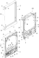
以下、発明の実施形態を図面に基づいて詳述する。図1〜図40は本発明をパチンコ機に採用した第1の実施形態を例示している。図1及び図2において、遊技機本体1は、外枠2と、この外枠2の前側に配置された前枠3とを備えている。前枠3は、左右方向一端側、例えば左端側に配置された上下方向の第1ヒンジ4を介して外枠2に開閉自在及び着脱自在に枢着されており、左右方向における第1ヒンジ4と反対側、例えば右端側に設けられた施錠手段5によって外枠2に対して閉状態で施錠可能となっている。
Hereinafter, embodiments of the invention will be described in detail with reference to the drawings. FIGS. 1 to 40 illustrate a first embodiment in which the present invention is adopted in a pachinko machine. In FIGS. 1 and 2, the gaming machine
前枠3は、本体枠6と、その本体枠6の前側に配置されたガラス扉7とを備えている。ガラス扉7は、左右方向一端側、例えば左端側に配置された上下方向の第2ヒンジ8を介して本体枠6に開閉自在及び着脱自在に枢着されており、施錠手段5によって本体枠6に対して閉状態で施錠可能となっている。なお、第1ヒンジ4と第2ヒンジ8とは例えば同一軸心となるように配置されている。
The
外枠2は、図2に示すように左右一対の縦枠材2a,2bと上下一対の横枠材2c,2dとで矩形状に形成されている。外枠2の前側下部には、例えば合成樹脂製の前カバー部材9が、下横枠材2dの前縁に沿って左右の縦枠材2a,2bの前側下部を連結するように装着されている。前カバー部材9は、左右の縦枠材2a,2bよりも前側に突出しており、その上側に閉状態の本体枠6が位置している。また外枠2には、第1ヒンジ4を構成する外枠上ヒンジ金具11が例えば左上部に、同じく外枠下ヒンジ金具12が左下部における前カバー部材9の上側に夫々配置されている。
As shown in FIG. 2, the
本体枠6は合成樹脂製で、前カバー部材9の上側で外枠2の前縁側に略当接可能な矩形状の枠部13と、この枠部13内の上部側に設けられた遊技盤装着部14と、枠部13内の下部側に設けられた下部装着部15とを例えば一体に備えている。遊技盤装着部14には、遊技盤16が例えば前側から着脱自在に装着され、下部装着部15には、その前側に発射手段17、下部スピーカ18等が配置されている。また本体枠6には、第1ヒンジ4を構成する本体枠上ヒンジ金具19と第2ヒンジ8を構成する本体枠上ヒンジ金具20とが例えば左上部に、第1,第2ヒンジ4,8を構成する本体枠下ヒンジ金具21が例えば左下部に夫々配置されている。
The
ガラス扉7は、本体枠6の前面側に対応する矩形状に形成された樹脂製の扉ベース22を備えている。この扉ベース22には、遊技盤16に形成された遊技領域23の前側に対応してガラス窓24の窓孔24aが形成されると共に、例えば窓孔24aの周囲に複数(ここでは4つ)の上部スピーカ25、送風演出手段26等の演出手段が配置され、それら上部スピーカ25等を前側から略覆う上装飾カバー27が装着されている。
The
また扉ベース22の下部前側には、本体枠6の後側に配置された払い出し手段28から払い出された遊技球を貯留して発射手段17に供給する上皿30、その上皿30が満杯のときの余剰球等を貯留する下皿31、発射手段17を作動させるために操作する発射ハンドル32等が配置され、更に上皿30、下皿31等を前側から略覆う下装飾カバー33が装着されている。下装飾カバー33は、例えば前向きの膨出状に形成されており、例えばその上部側に、遊技者が押下操作可能な演出ボタン34、十字操作手段35等の操作手段が設けられている。十字操作手段35は、例えば後側の上キー35a、前側の下キー35b、左側の左キー35c、右側の右キー35dの4つの操作部を備えている。
Further, on the lower front side of the
扉ベース22の背面側には、窓孔24aを後側から略塞ぐようにガラスユニット36が着脱自在に装着されると共に、第1,第2ヒンジ4,8側の縁部に沿って配置される上下方向のヒンジ端側補強板金37と、開閉端側の縁部に沿って配置される上下方向の開閉端側補強板金38と、窓孔24aの下側に配置される左右方向の下部補強板金39とがねじ止め等により着脱自在に固定されている。また扉ベース22には、第2ヒンジ8を構成するガラス扉上ヒンジ金具40が例えば左上部に、同じくガラス扉下ヒンジ金具41が例えば左下部に夫々配置されている。
A
また、例えば下部補強板金39の背面側には、球送りユニット42、下皿案内ユニット43等が装着されている。球送りユニット42は、上皿30内の遊技球を1個ずつ発射手段17に供給するためのもので、発射手段17の前側に対応して配置されている。下皿案内ユニット43は、上皿30が満杯となったときの余剰球、及び発射手段17により発射されたにも拘わらず遊技領域23に達することなく戻ってきたファール球を下皿31に案内するためのもので、例えば球送りユニット42に隣接してその第1,第2ヒンジ4,8側に配置されている。
Further, for example, a
図3に示すように、遊技盤16は例えばベニヤ板等で形成されたベース板45を備え、そのベース板45の前側に、発射手段17から発射された遊技球を案内するガイドレール46が環状に装着されると共に、そのガイドレール46の内側の遊技領域23に、中央表示枠ユニット47、始動入賞ユニット48、普通入賞ユニット49等のユニット部品の他、多数の遊技釘(図示省略)が配置されている。中央表示枠ユニット47は例えば遊技領域23の略中央における上部側に配置され、始動入賞ユニット48は中央表示枠ユニット47の下側に、普通入賞ユニット49は中央表示枠ユニット47の下側で始動入賞ユニット48の左側に、夫々ガイドレール46の内側に沿って配置されている。
As shown in FIG. 3, the
またそれら複数のユニット部品47〜49上には、普通図柄表示手段51、普通保留個数表示手段52、第1特別図柄表示手段53、第2特別図柄表示手段54等の各種表示手段の他、普通図柄始動手段55、第1特別図柄始動手段56、第2特別図柄始動手段57、大入賞手段58、複数の普通入賞手段59等が設けられている。また、ベース板45の後側には、液晶表示手段(画像表示手段、表示手段)60、複数種類、例えば4種類の可動演出手段61〜64等が裏取付ベース(図示省略)を介して装着されている。本実施形態では、液晶表示手段60は縦長状に配置されている。
Further, on the plurality of
中央表示枠ユニット47は、液晶表示手段60の表示枠を構成するもので、その略中央に液晶表示手段60に対応する表示窓70が形成され、ベース板45に形成された装着孔(図示省略)に対して前側から着脱自在に装着されている。この中央表示枠ユニット47は、ベース板45の前面に沿って装着孔の外側に配置され且つその前側を遊技球が通過可能な前面装着板71と、液晶表示手段60の前側における左右両側から上部側にわたる正面視略門形状に配置され且つ前面装着板71の内周側で前向きに突設された装飾枠72と、その装飾枠72の左右の下端部間に配置されるステージ73とを備えている。発射手段17により発射され、遊技領域23の上部側に進入した遊技球は、装飾枠72の頂部で左右に振り分けられ、中央表示枠ユニット47の左側の左流下経路74aと右側の右流下経路74bとの何れかを流下する。
The central
中央表示枠ユニット47には、左流下経路74a側と右流下経路74b側との少なくとも一方側、例えば左流下経路74a側に、遊技球が流入可能なワープ入口75が設けられている。ワープ入口75に流入した遊技球は、ステージ73上で左右方向に自由に転動した後、遊技領域23の左右方向中央に対応して設けられた中央落下部76とそれ以外の部分との何れかから前側に落下する。
The central
またステージ73の上側には、跳ね返り等による後側への遊技球の進入を阻止するための進入防止手段77が設けられている。進入防止手段77は、ステージ73の後側に沿って例えばベース板45と平行に立設される第1進入防止板77aと、その第1進入防止板77aの上縁部から前向きに突設される第2進入防止板77bとを例えば一体に備えている。なお、進入防止手段77は例えばその全体が透明であり、前側からその進入防止手段77を介して後側を視認可能となっている。
Further, on the upper side of the
中央表示枠ユニット47の後側には、図3及び図4に示すように左・右・上・下の4種類の可動演出手段61〜64が配置されている。左可動演出手段61は、図4(a)に示すように、左可動体61aと、この左可動体61aをその一端側で例えば前後方向の軸廻りに揺動自在に支持すると共に上下方向の昇降ガイド61bに沿って上下方向に移動可能な昇降支持体61cと、左可動体61aを昇降支持体61cに対して上揺動位置と下揺動位置との間で揺動駆動する揺動駆動手段61dと、昇降支持体61cを上昇降位置と下昇降位置との間で昇降駆動する昇降駆動手段61eとを備えている。
As shown in FIGS. 3 and 4, four types of movable effect means 61 to 64, left, right, up, and down, are arranged on the rear side of the central
左可動体61aは任意の立体形状(ここでは人間の手の形状)に形成されており、ステッピングモータ等よりなる揺動駆動手段61dと昇降駆動手段61eとにより、表示窓70の左側の横位置と、同じく左上部側の上位置と、同じく左下部側の下位置とに移動可能となっている。なお、横位置の場合には、昇降支持体61cが上昇降位置で、左可動体61aが昇降支持体61cに対して下揺動位置で夫々停止し、上位置の場合には、昇降支持体61cが上昇降位置で、左可動体61aが昇降支持体61cに対して上揺動位置で夫々停止し、下位置の場合には、昇降支持体61cが下昇降位置で、左可動体61aが昇降支持体61cに対して上揺動位置で夫々停止する。
The left
また左可動演出手段61は、昇降支持体61cが上昇降位置にあることを検出可能な上昇降位置検出手段81aと、昇降支持体61cが下昇降位置にあることを検出可能な下昇降位置検出手段81bと、左可動体61aが昇降支持体61cに対して上揺動位置にあることを検出可能な上揺動位置検出手段81cと、左可動体61aが昇降支持体61cに対して下揺動位置にあることを検出可能な下揺動位置検出手段81dとを備えている。
Further, the left movable effect means 61 has an upper elevating position detecting means 81a that can detect that the elevating
また右可動演出手段62は、例えば左可動演出手段61と左右略対象に形成されており、図4(a)に示すように、右可動体62aと、この右可動体62aをその一端側で例えば前後方向の軸廻りに揺動自在に支持すると共に上下方向の昇降ガイド62bに沿って上下方向に移動可能な昇降支持体62cと、右可動体62aを昇降支持体62cに対して上揺動位置と下揺動位置との間で揺動駆動する揺動駆動手段62dと、昇降支持体62cを上昇降位置と下昇降位置との間で昇降駆動する昇降駆動手段62eとを備えている。
Further, the right movable effect means 62 is formed so as to be substantially symmetrical with the left movable effect means 61, and as shown in FIG. 4A, the right
右可動体62aは任意の立体形状(ここでは人間の手の形状)に形成されており、ステッピングモータ等よりなる揺動駆動手段62dと昇降駆動手段62eとにより、表示窓70の右側の横位置と、同じく右上部側の上位置と、同じく右下部側の下位置とに移動可能となっている。なお、横位置の場合には、昇降支持体62cが上昇降位置で、右可動体62aが昇降支持体62cに対して下揺動位置で夫々停止し、上位置の場合には、昇降支持体62cが上昇降位置で、右可動体62aが昇降支持体62cに対して上揺動位置で夫々停止し、下位置の場合には、昇降支持体62cが下昇降位置で、右可動体62aが昇降支持体62cに対して上揺動位置で夫々停止する。
The right
また右可動演出手段62は、昇降支持体62cが上昇降位置にあることを検出可能な上昇降位置検出手段82aと、昇降支持体62cが下昇降位置にあることを検出可能な下昇降位置検出手段82bと、右可動体62aが昇降支持体62cに対して上揺動位置にあることを検出可能な上揺動位置検出手段82cと、右可動体62aが昇降支持体62cに対して下揺動位置にあることを検出可能な下揺動位置検出手段82dとを備えている。
Further, the right movable effect means 62 has an upper elevating position detecting means 82a that can detect that the elevating
なお本実施形態では、遊技モードを複数種類、例えば3種類の中から選択可能となっており、それら3種類の遊技モード毎に、左右の可動体61a,62aの位置が異なっている。即ち図5に示すように、左右の可動体61a,62aの位置は、第1モードでは共に横位置に、第2モードでは共に下位置に、第3モードでは共に上位置に設定されている。このように、左右の可動体61a,62aについては、遊技モード毎に原点位置が異なっており、例えば第1モードでは横位置が、第2モードでは下位置が、第3モードでは上位置が夫々原点位置となる。従って、左可動体61aの原点検出手段は、第1モードでは上昇降位置検出手段81aと下揺動位置検出手段81d、第2モードでは下昇降位置検出手段81bと上揺動位置検出手段81c、第3モードでは上昇降位置検出手段81aと上揺動位置検出手段81cであり、右可動体62aの原点検出手段は、第1モードでは上昇降位置検出手段82aと下揺動位置検出手段82d、第2モードでは下昇降位置検出手段82bと上揺動位置検出手段82c、第3モードでは上昇降位置検出手段82aと上揺動位置検出手段82cである。
In the present embodiment, a plurality of types of game modes, for example, three types can be selected, and the positions of the left and right
また上可動演出手段63は、図4(b)に示すように、上可動体63aと、この上可動体63aの左右両端側を夫々上下方向の昇降ガイド63b,63bに沿って上下方向に移動可能に支持する昇降支持体63c,63cと、昇降支持体63cを上昇降位置と下昇降位置との間で昇降駆動する昇降駆動手段63d,63dとを備えている。上可動体63aは、液晶表示手段60の前側に横長状に配置され、前面側には例えば任意の装飾(図示省略)が施されており、ステッピングモータ等よりなる左右の昇降駆動手段63d,63dの駆動により、例えば略水平な状態を保ったまま表示窓70の上端側の上位置と下端側の下位置との間で移動可能となっている。また上可動演出手段63は、上可動体63aが上位置にあることを検出可能な上位置検出手段83aと、同じく下位置にあることを検出可能な下位置検出手段83bとを備えている。なお本実施形態では、上可動体63aについては上位置を原点位置としており、上位置検出手段83aが原点検出手段となる。
Further, as shown in FIG. 4B, the upper movable effect means 63 moves the upper
また下可動演出手段64は、図4(b)に示すように、下可動体64aと、この下可動体64aを駆動するステッピングモータ等の下駆動手段64bとを備えている。下可動体64aは、液晶表示手段60の前側に横長状に配置され、前面側には例えば任意の装飾(図示省略)が施されており、例えば略水平な状態を保ったまま、下駆動手段64bの駆動により略全体が表示窓70よりも下側に位置する下位置と少なくとも一部が表示窓70内に位置する上位置との間で移動可能となっている。また下可動演出手段64は、下可動体64aが上位置にあることを検出可能な上位置検出手段84aと、同じく下位置にあることを検出可能な下位置検出手段84bとを備えている。なお本実施形態では、下可動体64aについては上位置を原点位置としており、上位置検出手段84aが原点検出手段となる。
Further, as shown in FIG. 4B, the lower movable effect means 64 includes a lower
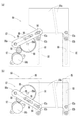
以下、下可動演出手段64の駆動機構について図6,図7を参照しつつ詳述する。下可動演出手段64の駆動機構は、下可動体64aを例えば左右両端側で夫々昇降移動可能に支持する左ベース体85及び右ベース体86と、下駆動手段64bと、下駆動手段64bの駆動力を下可動体64aに伝達する駆動力伝達手段87とを備えている。また駆動力伝達手段87は、下可動体64aの昇降移動に連動して揺動する駆動アーム88と、下駆動手段64bの回転動作を駆動アーム88の揺動動作に変換するためのクランクギヤ89とを備えている。
Hereinafter, the drive mechanism of the lower movable effect means 64 will be described in detail with reference to FIGS. 6 and 7. The drive mechanism of the lower movable effect means 64 drives the
左ベース体85及び右ベース体86は、表示窓70の下側左右に対応して中央表示枠ユニット47の後側に配置され、例えば裏取付ベースに着脱自在に固定されており、図6に示すように夫々上下方向の長孔状に形成されたガイド孔90,91を備えている。また下可動体64aには、左右両端側に各2つのスライド係合部92a,92b,93a,93bを備えており、左側のスライド係合部92a,92bがガイド孔90に、右側のスライド係合部93a,93bがガイド孔91に夫々摺動自在に係合することにより、下可動体64aは略水平な姿勢を保ったまま上下方向にスライド移動可能となっている。
The
駆動アーム88は、例えば細長板状に形成され、右ベース体86の後側に配置されており、その一端側(右端側)が右ベース体86により前後方向の回転軸88a廻りに回転自在に支持され、他端側(左端側)に形成された長手方向の第1ガイド孔94に下可動体64aのスライド係合部93aが摺動自在に係合している。なお、回転軸88aはスライド係合部93aの可動範囲の略中央に対応する高さ位置に配置されている。
The
クランクギヤ89は、例えば駆動アーム88の長手方向略中央に対応して右ベース体86とその後側の駆動アーム88との間に配置され、右ベース体86により前後方向の回転軸89a廻りに回転自在に支持されている。なお、回転軸89aは回転軸88aと略同じ高さ位置に配置されている。クランクギヤ89の例えば背面側には、外周部近傍に1つのスライド係合部95が突設されており、このスライド係合部95が、駆動アーム88の中央部付近に形成された長手方向の第2ガイド孔96に摺動自在に係合している。
The
また、右ベース体86の裏側には、下駆動手段64bと、この下駆動手段64bの駆動軸に固定された駆動ギヤ97と、この駆動ギヤ97とクランクギヤ89とを連動させる中継ギヤ98とが配置されている。これにより、下駆動手段64bが正/逆何れかの方向に作動すると、クランクギヤ89が回転し、それによってスライド係合部95が駆動アーム88の第2ガイド孔96内を摺動しつつ回転軸89a廻りに移動するため、駆動アーム88が揺動し、それによって下可動体64aは上位置(図6(a),図7(a))と下位置(図6(b),図7(b))との間で上下方向に移動する。なお下可動体64aが上位置にあるとき、図6(a)に示すように、クランクギヤ89における回転軸89aからスライド係合部95への向きと、駆動アーム88における第2ガイド孔96の向きとが互いに略直交してメカロック状態となる。下可動体64aが下位置にあるときについても同様である(図6(b))。
Further, on the back side of the
また例えばクランクギヤ89の前面側には、図7に示すように突条部99が周方向に沿って所定角度範囲内に設けられている。上位置検出手段84aと下位置検出手段84bとは、例えば透過型フォトセンサにより構成されており、下可動体64aが上位置にあるときには、図7(a)に示すように上位置検出手段84aが突条部99の一端側を検出することによりONとなり、また下可動体64aが下位置にあるときには、図7(b)に示すように下位置検出手段84bが突条部99の他端側を検出することによりONとなるように配置されている。
Further, for example, on the front surface side of the
なお本実施形態では、上位置検出手段84aがONになるのは、下可動体64aが上位置(原点位置)から下位置側に12ステップ分移動するまでの範囲内であるとする(図40参照)。
In the present embodiment, it is assumed that the upper
普通図柄始動手段55は、普通図柄表示手段51による普通図柄の変動表示を開始させるためのもので、遊技球が通過可能な通過ゲート等により構成され、遊技球の通過を検出する通過検出手段55aを備えている。この普通図柄始動手段55は、図3に示すように例えば中央表示枠ユニット47の右部における前面装着板71の前側に設けられており、右流下経路74bを流下する遊技球が通過可能となっている。
The normal symbol starting means 55 is for starting the variable display of the normal symbol by the normal symbol display means 51, and is composed of a passing gate or the like through which the game ball can pass, and the
普通図柄表示手段51は、普通図柄を変動表示するためのもので、複数個の普通図柄(例えば「○」「×」の2種類)に対応する複数個の発光体(例えばLED)を備え、例えば中央表示枠ユニット47の装飾枠72に配置されている。この普通図柄表示手段51は、普通図柄始動手段55が遊技球を検出することに基づいて複数の発光体が所定順序で発光するように点滅して、普通図柄始動手段55による遊技球検出時に取得した普通乱数情報に含まれる当たり判定乱数値が予め定められた当たり判定値と一致する場合には当たり態様(所定態様)に対応する例えば「○」側の発光体が点灯し、それ以外の場合には外れ態様に対応する例えば「×」側の発光体が点灯して停止する。普通図柄表示手段51の変動後の停止図柄が当たり態様となった場合には普通利益状態が発生する。
The ordinary symbol display means 51 is for displaying ordinary symbols in a variable manner, and includes a plurality of light emitters (for example, LEDs) corresponding to a plurality of ordinary symbols (for example, two types of “○” and “×”). For example, it is arranged in the
また、普通図柄表示手段51の図柄変動中と普通利益状態中とを含む普通保留期間中に普通図柄始動手段55が遊技球を検出した場合には、それによって取得された普通乱数情報が予め定められた上限保留個数、例えば4個を限度として保留記憶され、普通保留期間が終了する毎に1個ずつ消化されて普通図柄の変動が行われる。普通乱数情報の記憶個数(普通保留個数)は、普通保留個数表示手段52等によって遊技者に報知される。普通保留個数表示手段52は例えば中央表示枠ユニット47の装飾枠72に配置される。
Further, when the ordinary symbol starting means 55 detects a game ball during the ordinary holding period including the symbol change of the ordinary symbol display means 51 and the ordinary profit state, the ordinary random number information acquired by the detection is predetermined. The maximum number of reserved pieces, for example, 4 pieces, is held and stored, and each time the normal holding period ends, one piece is consumed and the normal symbol is changed. The stored number of ordinary random number information (ordinary hold number) is notified to the player by the ordinary hold number display means 52 or the like. The normal hold quantity display means 52 is arranged, for example, in the
第1特別図柄始動手段56は、第1特別図柄表示手段53による図柄変動を開始させるためのもので、開閉手段を有しない非開閉式入賞手段により構成され、入賞した遊技球を検出する遊技球検出手段56aを備えている。この第1特別図柄始動手段56は、例えば始動入賞ユニット48に設けられ、ステージ73の中央落下部76に対応してその下側に上向き開口状に配置されており、左流下経路74a側のワープ入口75からステージ73を経て入賞するルートが存在すること等により、右流下経路74bを流下してきた遊技球よりも左流下経路74aを流下してきた遊技球の方が高い確率で入賞可能となっている。なお、この第1特別図柄始動手段56に遊技球が入賞すると、1入賞当たり所定個数の遊技球が賞球として払い出される。
The first special symbol starting means 56 is for starting the symbol variation by the first special symbol display means 53, is composed of a non-opening / closing winning means having no opening / closing means, and is a game ball for detecting a winning game ball. The detection means 56a is provided. The first special symbol starting means 56 is provided in, for example, the
第2特別図柄始動手段57は、第2特別図柄表示手段54による図柄変動を開始させるためのもので、開閉部101の作動によって遊技球が入賞可能な開状態と入賞不可能(又は開状態よりも入賞困難)な閉状態とに変化可能な開閉式入賞手段により構成され、入賞した遊技球を検出する遊技球検出手段57aを備えており、普通図柄表示手段51の変動後の停止図柄が当たり態様(所定態様)となって普通利益状態が発生したときに、開閉部101が所定時間閉状態から開状態に変化するようになっている。
The second special symbol starting means 57 is for starting the symbol variation by the second special symbol display means 54, and the game ball can be won in the open state and cannot be won (or from the open state) by the operation of the opening /
この第2特別図柄始動手段57は、例えば中央表示枠ユニット47の右部における前面装着板71上で且つ普通図柄始動手段55の下流側に配置されており、左流下経路74aを流下してきた遊技球よりも右流下経路74bを流下してきた遊技球の方が高い確率で入賞可能となっている。開閉部101は例えば下部側に設けられた左右方向の回転軸廻りに揺動可能であり、閉状態では例えば前面装着板71と略面一となって遊技球が前側を通過可能となり、開状態では前面装着板71の前側で後ろ下がりの傾斜状となって遊技球を後向きに入賞させるようになっている。なお、この第2特別図柄始動手段57に遊技球が入賞すると、1入賞当たり所定個数の遊技球が賞球として払い出される。
The second special symbol starting means 57 is arranged, for example, on the
第1特別図柄表示手段53は、1個又は複数個、例えば1個の第1特別図柄を変動表示可能な7セグメント式等の表示手段により構成されており、第1特別図柄始動手段56が遊技球を検出することを条件に第1特別図柄を所定時間変動表示して、第1特別図柄始動手段56による遊技球検出時に取得された第1特別乱数情報に含まれる大当たり判定乱数値が予め定められた大当たり判定値と一致する場合には第1大当たり態様で、それ以外の場合には第1外れ態様で夫々停止するようになっている。第1特別図柄表示手段53の変動後の停止図柄が第1大当たり態様となった場合には第1特別利益状態が発生する。 The first special symbol display means 53 is composed of one or a plurality of, for example, a display means such as a 7-segment type capable of variablely displaying one first special symbol, and the first special symbol starting means 56 is a game. The first special symbol is variablely displayed for a predetermined time on condition that the ball is detected, and the jackpot determination random number value included in the first special random number information acquired when the game ball is detected by the first special symbol starting means 56 is predetermined. If it matches the jackpot determination value obtained, it stops in the first jackpot mode, and in other cases, it stops in the first missed mode. When the stop symbol after the change of the first special symbol display means 53 becomes the first jackpot mode, the first extraordinary profit state occurs.
第2特別図柄表示手段54は、1個又は複数個、例えば1個の第2特別図柄を変動表示可能な7セグメント式等の表示手段により構成されており、第2特別図柄始動手段57が遊技球を検出することを条件に第2特別図柄を所定時間変動表示して、第2特別図柄始動手段57による遊技球検出時に取得された第2特別乱数情報に含まれる大当たり判定乱数値が予め定められた大当たり判定値と一致する場合には第2大当たり態様で、それ以外の場合には第2外れ態様で夫々停止するようになっている。第2特別図柄表示手段54の変動後の停止図柄が第2大当たり態様となった場合には第2特別利益状態が発生する。 The second special symbol display means 54 is composed of one or a plurality of, for example, a display means such as a 7-segment type capable of variablely displaying one second special symbol, and the second special symbol starting means 57 is a game. The second special symbol is displayed in a predetermined time variation on the condition that the ball is detected, and the jackpot determination random number value included in the second special random number information acquired when the game ball is detected by the second special symbol starting means 57 is predetermined. If it matches the jackpot determination value obtained, it stops in the second jackpot mode, and in other cases, it stops in the second missed mode. When the stop symbol after the change of the second special symbol display means 54 becomes the second jackpot mode, the second extraordinary profit state occurs.
第1,第2特別図柄表示手段53,54は、例えば中央表示枠ユニット47の装飾枠72に配置されている。第1,第2特別図柄は、例えば数字図柄等ではなく、それ自体としては特別な意味を持たない線と点の組み合わせ等よりなる複数種類の図柄で構成され、それらの図柄のうちの1又は複数が第1,第2大当たり態様、それ以外が第1,第2外れ態様となっている。
The first and second special symbol display means 53 and 54 are arranged, for example, in the
また、第1特別図柄表示手段53の図柄変動中、第2特別図柄表示手段54の図柄変動中及び第1,第2特別利益状態中を含む特別保留期間中に第1,第2特別図柄始動手段56,57が遊技球を検出した場合には、そのときに取得した第1,第2特別乱数情報を夫々予め定められた上限保留個数、例えば各4個を限度として保留記憶する。そして、特別保留期間が終了した時点で第2特別図柄側の保留記憶が1以上の場合(第2特別図柄に関する図柄変動開始条件が成立した場合)にはその第2特別図柄の保留記憶を消化することにより第2特別図柄の変動を行い、第1特別図柄側の保留記憶のみが1以上の場合(第1特別図柄に関する図柄変動開始条件が成立した場合)にはその第1特別図柄の保留記憶を消化することにより第1特別図柄の変動を行う。このように本実施形態では、第1特別図柄と第2特別図柄とが共に変動中になることはなく、また第1特別図柄側と第2特別図柄側との両方に保留記憶がある場合には、第2特別図柄の変動を優先的に行うようになっている。なお、第1,第2特別乱数情報の記憶個数(第1,第2特別保留個数)は、液晶表示手段60等によって遊技者に報知される。 In addition, the first and second special symbols are started during the special holding period including the symbol change of the first special symbol display means 53, the symbol change of the second special symbol display means 54, and the first and second special profit states. When the means 56 and 57 detect the game ball, the first and second special random number information acquired at that time are stored and stored in a predetermined upper limit holding number, for example, four each. Then, when the hold memory on the second special symbol side is 1 or more at the end of the special hold period (when the symbol change start condition for the second special symbol is satisfied), the hold memory of the second special symbol is exhausted. By doing so, the second special symbol is changed, and when only the reserved memory on the first special symbol side is 1 or more (when the symbol change start condition for the first special symbol is satisfied), the first special symbol is reserved. The first special symbol is changed by digesting the memory. As described above, in the present embodiment, when both the first special symbol and the second special symbol do not change, and both the first special symbol side and the second special symbol side have reserved memory. Is designed to give priority to the change of the second special symbol. The number of stored first and second special random number information (first and second special reserved numbers) is notified to the player by the liquid crystal display means 60 and the like.
大入賞手段(特別入賞手段)58は、遊技球が入賞可能な開状態と入賞不可能な閉状態とに切り換え可能な開閉板102を備えた開閉式入賞手段で、入賞した遊技球を検出する遊技球検出手段58aを備えており、第1,第2特別図柄表示手段53,54の第1,第2特別図柄が変動後に第1,第2大当たり態様で停止した場合に発生する第1,第2特別利益状態中に、開閉板102が所定の大当たり開放パターンに従って前側に開放して、その上に落下した遊技球を内部へと入賞させるようになっている。この大入賞手段58は、例えば中央表示枠ユニット47の右側下部で第2特別図柄始動手段57の下流側に配置されており、左流下経路74aを流下してきた遊技球よりも右流下経路74bを流下してきた遊技球の方が高い確率で入賞可能となっている。この大入賞手段58に遊技球が入賞すると、1入賞当たり所定個数の遊技球が賞球として払い出される。本実施形態では、大入賞手段58への1入賞当たりの賞球数を12個とする。なお以下の説明では、第1特別利益状態と第2特別利益状態とを合わせて「大当たり遊技」という。
The large winning means (special winning means) 58 is an opening / closing type winning means provided with an opening /
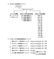
本実施形態では図10に示すように、第1特別図柄が第1大当たり態様となった場合に発生する大当たり遊技(第1特別利益状態)がA1〜A4の4種類、第2特別図柄が第2大当たり態様となった場合に発生する大当たり遊技(第2特別利益状態)がB1〜B10の10種類設けられており、それら各大当たり遊技に対して複数種類の大当たり開放パターンの何れかが割り当てられている。 In this embodiment, as shown in FIG. 10, there are four types of jackpot games (first special profit state) that occur when the first special symbol becomes the first jackpot mode, and the second special symbol is the first. Ten types of jackpot games (second special profit state) that occur when two jackpot modes are adopted are provided, and one of a plurality of types of jackpot opening patterns is assigned to each of these jackpot games. ing.
図10に示すように、本実施形態の大当たり開放パターンには15R/15R、10R/15R、6R/15R、4R/15R、10R/10R、6R/10Rの6種類があり、大当たり遊技A1,A2,B1,B2,B4〜B7には15R/15R開放パターンが、大当たり遊技A3,B9には6R/15R開放パターンが、大当たり遊技A4には6R/10R開放パターンが、大当たり遊技B3には10R/10R開放パターンが、大当たり遊技B8には10R/15R開放パターンが、大当たり遊技B10には4R/15R開放パターンが夫々割り当てられている。
As shown in FIG. 10, there are six types of jackpot opening patterns of the present embodiment: 15R / 15R, 10R / 15R, 6R / 15R, 4R / 15R, 10R / 10R, 6R / 10R, and jackpot games A1 and A2. , B1, B2, B4 to B7 have a 15R / 15R open pattern, jackpot games A3 and B9 have a 6R / 15R open pattern, jackpot game A4 has a 6R / 10R open pattern, and jackpot game B3 has a 10R /
ここで「○R/□R」における分母側は総ラウンド数で、これが15R、10Rの場合には夫々大当たりラウンドを15回、10回行うことを示している。なお、大当たりラウンドには例えば「出玉あり」と「出玉なし」の2種類があり、「○R/□R」における分子側は総ラウンド数のうちの出玉ありラウンドの数を示している。 Here, the denominator side in "○ R / □ R" is the total number of rounds, and when this is 15R and 10R, it is shown that the jackpot rounds are performed 15 times and 10 times, respectively. There are two types of jackpot rounds, for example, "with balls" and "without balls", and the numerator side of "○ R / □ R" indicates the number of rounds with balls out of the total number of rounds. There is.
出玉ありラウンドは、大入賞手段58の開放後、その大入賞手段58への入賞個数が所定個数(最大カウント数)に達するか、所定時間経過した時点で大入賞手段58を閉じるようになっており(所定開動作)、遊技者が右流下経路74b側の大入賞手段58を狙って普通に右打ちをすれば最大カウント数の遊技球を容易に入賞させることができ、所定個数の賞球を容易に獲得することができる。なお、本実施形態では最大カウント数を8とする。
In the round with a payout, after the big winning means 58 is opened, the big winning means 58 is closed when the number of winnings to the big winning means 58 reaches a predetermined number (maximum count number) or a predetermined time elapses. (Predetermined opening operation), if the player normally hits right at the large winning means 58 on the
一方、出玉なしラウンドは大入賞手段58が極短時間だけ1又は複数回開放するようになっており、遊技者が右打ちをしても遊技球を入賞させることは困難で、遊技者は賞球の獲得を期待できない。従って、例えば4R/15Rと6R/10Rとを比較すると、総ラウンド数は15Rと10Rで前者の方が多いが、出玉ありラウンド数は4Rと6Rで後者の方が多いため、後者の方が遊技者に有利である。 On the other hand, in the round without a ball, the large winning means 58 is opened once or multiple times for a very short time, and it is difficult for the player to win the game ball even if the player hits right. I can't expect to win a prize ball. Therefore, for example, when comparing 4R / 15R and 6R / 10R, the total number of rounds is 15R and 10R, which is more than the former, but the number of rounds with balls is 4R and 6R, which is more than the latter. Is advantageous to the player.
なお、出玉なしラウンドは例えば出玉ありラウンドが全て終了した後に実行される。従って、例えば6R/15R開放パターンの場合には、第1R〜第6Rが出玉ありラウンド、第7R〜第15Rが出玉なしラウンドとなる。 In addition, the round without a ball is executed after, for example, all the rounds with a ball are completed. Therefore, for example, in the case of a 6R / 15R open pattern, the 1st R to the 6th R are rounds with balls, and the 7th R to 15R are rounds without balls.
普通入賞手段59は、開閉手段を有しない非開閉式入賞手段で、入賞した遊技球を検出する遊技球検出手段59aを備えており、例えば左流下経路74a側の普通入賞ユニット49に複数個、また右流下経路74b側の例えば大入賞手段58の側方にも例えば1個配置されている。この普通入賞手段59に遊技球が入賞すると、1入賞当たり所定個数の遊技球が賞球として払い出される。
The ordinary winning means 59 is a non-opening / closing type winning means having no opening / closing means, and includes a game ball detecting means 59a for detecting a winning game ball. Further, for example, one is also arranged on the side of, for example, the large winning means 58 on the
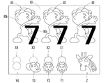
また液晶表示手段60には、例えば第1,第2特別図柄表示手段53,54による第1,第2特別図柄の変動表示と並行して演出図柄80が変動表示される他、第1,第2特別保留個数を示す第1,第2保留表示画像X1〜X4,Y1〜Y4等の各種画像を表示可能となっている。
Further, on the liquid crystal display means 60, for example, the
ここで演出図柄80は、図15等に示すように、例えば1〜8等の数字で構成される数字部80aと、この数字部に付随するキャラクタその他の装飾部80bとの結合で構成され、例えば所定方向に複数列(ここでは左右方向に3列)で夫々変動可能であり、例えば第1,第2特別図柄の変動開始と略同時に所定の変動パターンに従って縦スクロール等による変動を開始すると共に、第1,第2特別図柄の変動停止と略同時に最終停止するように、左、右、中等の所定の順序で停止するようになっている。なお演出図柄80では、例えば全て同じ図柄で揃った場合が大当たり演出態様、それ以外が外れ演出態様となっており、第1,第2特別図柄が第1,第2大当たり態様となる場合には演出図柄80は大当たり演出態様となり、第1,第2特別図柄が第1,第2外れ態様となる場合には演出図柄80は外れ演出態様となる。
Here, as shown in FIG. 15 and the like, the
図8は本パチンコ遊技機の制御系のブロック図である。図8において、主制御基板(主制御手段)103は遊技制御を統括するもので、普通図柄表示手段51、第1,第2特別図柄表示手段53,54等の表示手段の他、普通図柄始動手段55に設けられた通過検出手段55a、各入賞手段56〜59に設けられた遊技球検出手段56a〜59a等が接続されている。
FIG. 8 is a block diagram of the control system of this pachinko gaming machine. In FIG. 8, the main control board (main control means) 103 controls the game control, and in addition to the display means such as the normal symbol display means 51, the first and second special symbol display means 53, 54, the normal symbol start. The
また主制御基板103の下位には、演出制御基板104、液晶制御基板105、払出制御基板106、発射制御基板107等のサブ制御基板が接続されている。演出制御基板(サブ制御手段)104は、主制御基板103からの制御コマンドに基づいて演出制御を行うもので、スピーカ18,25、電飾手段108、可動演出手段61〜64、送風演出手段26等の各種演出手段の他、演出ボタン34、十字操作手段35等の操作手段が接続されている。なお電飾手段108は、上下の装飾カバー27,33内の他、遊技盤16上の各種ユニット部品に配置されたLED等により構成されている。
Further, sub-control boards such as an effect control board 104, a liquid crystal control board 105, a payout control board 106, and a launch control board 107 are connected below the
液晶制御基板105は、演出制御基板104からの制御コマンドに基づいて液晶表示手段60を制御するものである。また払出制御基板106は、主制御基板103からの制御コマンドに基づいて払い出し手段28を制御するもので、その下位に発射制御基板107が接続されている。発射制御基板107は、払出制御基板106からの発射制御信号、発射ハンドル32からの操作信号等に基づいて発射手段17を制御するようになっている。発射制御基板107は例えば発射手段17の裏側等に配置されている。
The liquid crystal control board 105 controls the liquid crystal display means 60 based on a control command from the effect control board 104. Further, the payout control board 106 controls the payout means 28 based on a control command from the
主制御基板103は、CPU,ROM,RAM等により構成される普通乱数作成処理手段111、普通始動口チェック処理手段112、普通乱数記憶手段113、普通図柄処理手段114、普通図柄表示制御手段115、普通利益状態発生手段116、特別乱数作成処理手段117、特別始動口チェック処理手段118、特別乱数記憶手段119、特別図柄処理手段120、特別図柄表示制御手段121、大当たり遊技発生手段122、特別遊技状態発生手段123、入賞処理手段124、制御コマンド送信手段125等を備えている。
The
普通乱数作成処理手段111は、変動後の普通図柄を当たり態様とするか否かの判定に用いる当たり判定乱数等を所定時間毎に繰り返し発生するように構成されている。普通始動口チェック処理手段112は、普通図柄始動手段55による遊技球の検出に基づく処理を行うもので、普通図柄始動手段55が遊技球を検出することに基づいて、普通乱数作成処理手段111で作成された当たり判定乱数値等の普通乱数情報を取得し、その普通乱数情報を予め定められた上限保留個数(例えば4個)を限度として先入れ先出し式の普通乱数記憶手段113に記憶させるように構成されている。 The ordinary random number creating processing means 111 is configured to repeatedly generate a hit determination random number or the like used for determining whether or not the changed ordinary symbol is the hit mode at predetermined time intervals. The normal start port check processing means 112 performs processing based on the detection of the game ball by the normal symbol starting means 55, and the normal random number creation processing means 111 is based on the fact that the normal symbol starting means 55 detects the game ball. It is configured to acquire the created ordinary random number information such as the hit determination random number value and store the ordinary random number information in the first-in first-out type ordinary random number storage means 113 up to a predetermined upper limit holding number (for example, 4). Has been done.
普通図柄処理手段114は、普通図柄の変動表示に関する処理を行うもので、普通図柄表示手段51が変動表示可能な状態となり且つ普通乱数記憶手段113に1個以上の当たり判定乱数値が記憶されていること(普通保留個数が1以上であること)を条件に、普通乱数記憶手段113に記憶されている普通乱数情報の待ち行列の先頭から当たり判定乱数値を取り出し、その当たり判定乱数値が予め定められた当たり判定値と一致するか否かに応じて当たり/外れの判定を行う当たり判定機能、当たり/外れの判定結果に基づいて普通図柄の変動後の停止図柄の種類を選択する普通停止図柄選択機能、普通図柄の変動時間を選択する変動時間選択機能等を備えている。 The ordinary symbol processing means 114 performs processing related to variable display of ordinary symbols, and the ordinary symbol display means 51 is in a state where variable display is possible, and one or more hit determination random numbers are stored in the ordinary random number storage means 113. The hit determination random number value is taken out from the beginning of the queue of the ordinary random number information stored in the ordinary random number storage means 113 on condition that the number is (ordinary holding number is 1 or more), and the hit determination random number value is set in advance. A hit judgment function that judges hit / miss according to whether or not it matches the specified hit judgment value, and a normal stop that selects the type of stop symbol after the normal symbol changes based on the hit / miss judgment result. It is equipped with a symbol selection function, a fluctuation time selection function for selecting the fluctuation time of a normal symbol, and the like.
普通図柄表示制御手段115は、普通図柄処理手段114による普通図柄処理に基づいて普通図柄表示手段51の表示制御を行うもので、普通図柄表示手段51が変動表示可能な状態となり且つ普通乱数記憶手段113に1個以上の普通乱数情報が記憶されていること(普通保留個数が1以上であること)を条件に普通図柄表示手段51による普通図柄の変動を開始させ、普通図柄処理手段114で選択された変動時間が経過することに基づいて、同じく普通図柄処理手段114で選択された停止図柄で普通図柄の変動を停止させるようになっている。 The ordinary symbol display control means 115 controls the display of the ordinary symbol display means 51 based on the ordinary symbol processing by the ordinary symbol processing means 114, and the ordinary symbol display means 51 is in a state where variable display is possible and the ordinary random number storage means. On the condition that one or more ordinary random number information is stored in 113 (the number of ordinary pending numbers is 1 or more), the ordinary symbol display means 51 starts to change the ordinary symbol, and the ordinary symbol processing means 114 selects it. Based on the elapse of the changed fluctuation time, the fluctuation of the normal symbol is stopped by the stop symbol also selected by the normal symbol processing means 114.
普通利益状態発生手段116は、普通図柄処理手段114による当たり判定の結果が当たりとなることに基づいて普通図柄表示手段51の変動後の停止図柄が当たり態様となった場合に、第2特別図柄始動手段57が例えば複数種類の開閉パターンの何れかに従って開状態に変化する普通利益状態を発生させるようになっている。本実施形態では、図9に示すように、通常開閉パターン(例えば0.2秒×1回開放)と、この通常開閉パターンよりも開放時間が大となるように設定された延長開閉パターン(例えば2秒×3回開放)の2種類の開閉パターンが設定されており、後述する開放延長状態中の場合(開放延長あり)には延長開閉パターンが、それ以外の場合(開放延長なし)には通常開閉パターンが夫々選択されるようになっている。 The ordinary profit state generating means 116 is the second special symbol when the stop symbol after the change of the ordinary symbol display means 51 becomes a hit mode based on the result of the hit determination by the ordinary symbol processing means 114. The starting means 57 is adapted to generate a normal profit state that changes to an open state according to, for example, any of a plurality of types of open / close patterns. In the present embodiment, as shown in FIG. 9, a normal opening / closing pattern (for example, 0.2 seconds × 1 opening) and an extended opening / closing pattern (for example) set so that the opening time is longer than this normal opening / closing pattern. Two types of opening / closing patterns (2 seconds x 3 times opening) are set. In the case of the opening extension state (with opening extension) described later, the extension opening / closing pattern is set, and in other cases (without opening extension). Normally, the opening / closing pattern is selected for each.
特別乱数作成処理手段117は、大当たり/外れの判定に用いる大当たり判定乱数、特別図柄の変動後の停止図柄等の選択に用いる図柄判定乱数、変動パターンの選択に用いる変動パターン乱数、その他の所定の乱数を繰り返し発生する特別乱数作成処理を行うように構成されている。 The special random number creation processing means 117 includes a jackpot determination random number used for determining jackpot / miss, a symbol determination random number used for selecting a stop symbol after a change of a special symbol, a variation pattern random number used for selecting a variation pattern, and other predetermined random numbers. It is configured to perform a special random number creation process that repeatedly generates random numbers.
特別始動口チェック処理手段118は、第1,第2特別図柄始動手段56,57への遊技球の入賞に基づく処理を行うもので、第1,第2特別図柄始動手段(図柄始動手段)56,57の何れかに遊技球が入賞することに基づいて、特別乱数作成処理手段117で作成された大当たり判定乱数値、大当たり図柄乱数値等の第1,第2特別乱数情報(未だ開始されていない図柄の変動表示に関する特定情報)を取得し、その第1,第2特別乱数情報を予め定められた上限保留個数(例えば4個)を限度として特別乱数記憶手段(乱数記憶手段、保留記憶手段)119に記憶させると共に、増加後の第1,第2特別保留個数等を指定する第1,第2保留増加コマンドを制御コマンド送信手段125を介して演出制御基板104に送信するように構成されている。 The special starting port check processing means 118 performs processing based on the winning of the game ball to the first and second special symbol starting means 56 and 57, and the first and second special symbol starting means (symbol starting means) 56. The first and second special random number information such as the jackpot determination random number value and the jackpot symbol random number value created by the special random number creation processing means 117 based on the winning of the game ball in any of, 57 (still started). The special random number storage means (random number storage means, hold storage means) is obtained by acquiring (specific information regarding the variable display of no symbol) and limiting the first and second special random number information to a predetermined upper limit holding number (for example, 4). ) 119, and the first and second hold increase commands for designating the first and second special hold numbers after the increase are transmitted to the effect control board 104 via the control command transmission means 125. ing.
また、特別始動口チェック処理手段118は先読み判定手段118aを備えている。この先読み判定手段118aは、第1,第2特別図柄始動手段56,57に遊技球が入賞したときに取得される第1,第2特別乱数情報について、例えばその取得時に、第1,第2特別乱数情報に含まれる大当たり判定乱数値が第1,第2大当たり判定値と一致するか否か等について先読み判定を行うようになっている。この先読み判定結果は、例えば第1,第2特別図柄始動手段56,57の何れかに遊技球が入賞することに基づいて送信される第1,第2保留増加コマンドにより演出制御基板104等に伝達される。 Further, the special start port check processing means 118 includes a look-ahead determination means 118a. The look-ahead determination means 118a has, for example, the first and second special random number information acquired when the game ball wins the first and second special symbol starting means 56 and 57, for example, at the time of acquisition. The pre-reading determination is performed as to whether or not the jackpot determination random number value included in the special random number information matches the first and second jackpot determination values. This look-ahead determination result is, for example, sent to the effect control board 104 or the like by the first or second hold increase command transmitted based on the winning of the game ball to any of the first and second special symbol starting means 56 and 57. Be transmitted.
特別図柄処理手段120は、第1,第2特別図柄の変動表示に関する処理を行うもので、第1,第2特別図柄表示手段53,54が変動表示可能な状態となったときに、第2特別保留個数が1以上であれば第2特別乱数情報の待ち行列から、第1特別保留個数のみが1以上であれば第1特別乱数情報の待ち行列からその先頭の大当たり判定乱数値を取り出し、その大当たり判定乱数値が予め定められた大当たり判定値と一致するか否かに応じて大当たり/外れの判定を行う大当たり判定機能、大当たり判定の結果に応じて、第1,第2特別乱数情報に含まれる大当たり図柄乱数値等に基づいて第1,第2特別図柄の変動後の停止図柄を選択する特別停止図柄選択機能、大当たり判定の結果に応じて、第1,第2特別図柄の変動パターンを複数種類の中から選択する変動パターン選択機能等を備えている。 The special symbol processing means 120 performs processing related to the variable display of the first and second special symbols, and when the first and second special symbol display means 53 and 54 are in a state where the variable display is possible, the second special symbol processing means 120 is used. If the number of special reservations is 1 or more, the first jackpot determination random number value is extracted from the queue of the second special random number information, and if only the number of special reservations is 1 or more, the queue of the first special random number information is extracted. The jackpot judgment function that judges jackpot / miss according to whether or not the jackpot judgment random number value matches a predetermined jackpot judgment value, and the first and second special random number information according to the result of the jackpot judgment. A special stop symbol selection function that selects the stop symbol after the change of the first and second special symbols based on the included jackpot symbol random number value, etc., and the fluctuation pattern of the first and second special symbols according to the result of the jackpot judgment. It is equipped with a variable pattern selection function that selects from multiple types.
本実施形態の大当たり遊技A1〜A4,B1〜B10(図10)は、第1,第2特別図柄が第1,第2大当たり態様となる場合の停止図柄に対応している。また図10に示すように、大当たり遊技A1〜A4,B1〜B10には、後述する特別遊技状態として確変状態と時短状態との何れかが紐付けられている。 The jackpot games A1 to A4 and B1 to B10 (FIG. 10) of the present embodiment correspond to the stop symbols when the first and second special symbols are the first and second jackpot modes. Further, as shown in FIG. 10, the jackpot games A1 to A4 and B1 to B10 are associated with either a probabilistic state or a time saving state as a special game state described later.
また本実施形態では、演出図柄80の変動パターンとして、リーチを経ることなく外れ態様となるリーチなし変動パターン、リーチ成立後にリーチ演出Aを実行して外れ態様又は大当たり態様となるリーチA外れ/大当たり変動パターン、リーチ成立後にリーチ演出Bを実行して外れ態様又は大当たり態様となるリーチB外れ/大当たり変動パターン、リーチ成立後にリーチ演出Cを実行して大当たり態様となるリーチC大当たり変動パターンの5種類が設けられており、大当たり判定結果に応じて、図22に示す変動パターン選択テーブルに基づいて各変動パターンが選択されるようになっている。図22の例では、大当たり判定結果が外れの場合には、リーチなし、リーチA外れ、リーチB外れの3つの変動パターンが245:5:1の選択率で選択され、大当たり判定結果が大当たり(非確変)の場合には、リーチA大当たり、リーチB大当たりの2つの変動パターンが80:171の選択率で選択され、大当たり判定結果が大当たり(確変)の場合には、リーチA大当たり、リーチB大当たり、リーチC大当たりの3つの変動パターンが71:170:10の選択率で選択される。
Further, in the present embodiment, as the variation pattern of the
図22より明らかなように、大当たり確率を1/300とすると、大当たり遊技発生の信頼度(以下、大当たり信頼度という)は、リーチなし変動パターンが0%、リーチA変動パターンが9.2%、リーチB変動パターンが53.3%、リーチC変動パターンが100%となっており、また確変状態を伴う大当たり遊技発生の信頼度(以下、確変大当たり信頼度という)は、リーチなし変動パターンが0%、リーチA変動パターンが4.3%、リーチB変動パターンが26.6%、リーチC変動パターンが100%となっている。 As is clear from FIG. 22, assuming that the jackpot probability is 1/300, the reliability of the jackpot game occurrence (hereinafter referred to as the jackpot reliability) is 0% for the non-reach fluctuation pattern and 9.2% for the reach A fluctuation pattern. , The reach B fluctuation pattern is 53.3%, the reach C fluctuation pattern is 100%, and the reliability of the jackpot game occurrence with the probability variation state (hereinafter referred to as the probability variation jackpot reliability) is the reachless variation pattern. The reach A fluctuation pattern is 0%, the reach A fluctuation pattern is 4.3%, the reach B fluctuation pattern is 26.6%, and the reach C fluctuation pattern is 100%.
また第1,第2特別図柄の変動開始時には、減少後の第1,第2特別保留個数等を指定する第1,第2保留減少コマンド、演出図柄80の変動パターンを指定する変動パターンコマンド、第1,第2特別図柄の停止図柄を指定する図柄指定コマンド等が制御コマンド送信手段125を介して演出制御基板104に送信される。一方、第1,第2特別保留個数が共に0の状態で第1,第2特別図柄の変動が終了する等により第1,第2特別図柄の変動待機状態となった場合には、客待ちデモコマンドが制御コマンド送信手段125を介して演出制御基板104に送信される。
Further, at the start of the fluctuation of the first and second special symbols, the first and second hold reduction commands for designating the first and second special hold counts after the reduction, the fluctuation pattern command for specifying the fluctuation pattern of the
特別図柄表示制御手段121は、第1,第2特別図柄表示手段(図柄表示手段)53,54の表示制御を行うもので、特別図柄処理手段120による特別図柄処理に基づいて、第1特別図柄表示手段53又は第2特別図柄表示手段54による第1,第2特別図柄の変動を開始させると共に、選択された変動パターンに対応する変動時間が経過することに基づいて、選択された停止図柄で第1,第2特別図柄の変動を停止させるようになっている。なお、第1,第2特別図柄の変動終了時には、演出図柄80の変動停止を指示する変動停止コマンドが制御コマンド送信手段125を介して演出制御基板104に送信される。
The special symbol display control means 121 controls the display of the first and second special symbol display means (symbol display means) 53 and 54, and the first special symbol is based on the special symbol processing by the special symbol processing means 120. At the selected stop symbol based on the fact that the variation of the first and second special symbols by the display means 53 or the second special symbol display means 54 is started and the variation time corresponding to the selected variation pattern elapses. The fluctuation of the first and second special symbols is stopped. At the end of the fluctuation of the first and second special symbols, a fluctuation stop command instructing the fluctuation stop of the
大当たり遊技発生手段(利益状態発生手段)122は、遊技者に有利な大当たり遊技(第1,第2特別利益状態)を発生させるもので、特別図柄処理手段120で大当たりの判定結果(特定結果)が得られ、それに基づいて第1,第2特別図柄の変動後の停止図柄が第1,第2大当たり態様(特定態様)となった場合に、大入賞手段58を所定の開放パターンに従って開放する大当たり遊技(特別遊技)を発生させるように構成されている。 The jackpot game generating means (profit state generating means) 122 generates a jackpot game (first and second special profit states) that is advantageous to the player, and the special symbol processing means 120 determines the jackpot determination result (specific result). When the stop symbol after the change of the first and second special symbols becomes the first and second big hit mode (specific mode) based on the above, the big winning means 58 is opened according to a predetermined opening pattern. It is configured to generate a jackpot game (special game).
本実施形態では、図10に示すように第1特別図柄が第1大当たり態様となった場合にはA1〜A4の4種類の大当たり遊技の何れかを、第2特別図柄が第2大当たり態様となった場合にはB1〜B10の10種類の大当たり遊技の何れかを実行する。各大当たり遊技に対応する大当たり開放パターンは図10に示すとおりである。例えば大当たり遊技A1では出玉ありラウンドを15ラウンド実行し、大当たり遊技B10では出玉ありラウンドを4ラウンドと出玉なしラウンドを11ラウンド実行する。 In the present embodiment, as shown in FIG. 10, when the first special symbol is the first jackpot mode, any one of the four types of jackpot games A1 to A4 is used, and the second special symbol is the second jackpot mode. If this happens, one of the 10 types of jackpot games B1 to B10 is executed. The jackpot opening pattern corresponding to each jackpot game is as shown in FIG. For example, in the jackpot game A1, 15 rounds with balls are executed, and in the jackpot game B10, 4 rounds with balls and 11 rounds without balls are executed.
特別遊技状態発生手段123は、大当たり遊技の終了後に遊技者に有利な特別遊技状態を発生させるものである。特別遊技状態は、高確率状態と開放延長状態との組み合わせにより、例えば高確率状態が発生し開放延長状態が発生しない「潜確状態」、高確率状態と開放延長状態とが共に発生する「確変状態」、高確率状態が発生せず、開放延長状態が発生する「時短状態」の3種類が考えられる。なお、高確率状態と開放延長状態とが共に発生していない状態が通常遊技状態である。 The special game state generating means 123 generates a special game state that is advantageous to the player after the end of the jackpot game. The special gaming state is a combination of a high probability state and an open extension state, for example, a "latent state" in which a high probability state occurs and an open extension state does not occur, and a "probability change" in which both a high probability state and an open extension state occur. There are three possible types: "state" and "time saving state" in which the open extension state does not occur and the high probability state does not occur. The normal gaming state is a state in which neither the high probability state nor the open extension state occurs.
高確率状態中は、それ以外の低確率状態中よりも大当たり判定値の数を多くすることにより、第1,第2特別図柄が大当たり態様となる確率を高確率に設定するようになっている。 In the high probability state, the probability that the first and second special symbols are in the jackpot mode is set to a high probability by increasing the number of jackpot determination values as compared with the other low probability states. ..
また開放延長状態中は、第2特別図柄始動手段57の開閉パターンが通常開閉パターン(例えば0.2秒×1回開放)から延長開閉パターン(例えば2秒×3回開放)に切り替えられるが(図9)、それ以外にも、第1,第2特別図柄に関して、第1,第2特別図柄表示手段53,54の変動時間が夫々通常変動時間よりも短い短縮変動時間に切り替えられ、普通図柄に関して、当たり確率が通常確率(例えば1/10)から高確率(例えば1/1.3)に、変動時間が通常変動時間(例えば27秒)から短縮変動時間(例えば2.7秒)に、夫々切り替えられる(図9)ようになっている。 Further, during the open extension state, the opening / closing pattern of the second special symbol starting means 57 is switched from the normal opening / closing pattern (for example, 0.2 seconds × 1 opening) to the extended opening / closing pattern (for example, 2 seconds × 3 times opening) ( In addition to that, with respect to the first and second special symbols, the fluctuation time of the first and second special symbol display means 53 and 54 is switched to a shortened fluctuation time shorter than the normal fluctuation time, respectively, and the normal symbol is displayed. With respect to, the hit probability changes from the normal probability (for example, 1/10) to the high probability (for example, 1 / 1.3), and the fluctuation time changes from the normal fluctuation time (for example, 27 seconds) to the shortened fluctuation time (for example, 2.7 seconds). Each can be switched (Fig. 9).
なお本実施形態では、図10に示すように大当たり遊技の種別毎に「確変状態」と「時短状態」との何れかを発生させ、例えば次の大当たり遊技が発生するか、それまでに第1,第2特別図柄が所定回数変動した場合に確変状態又は時短状態を終了させるようになっている。 In this embodiment, as shown in FIG. 10, either a "probability change state" or a "time saving state" is generated for each type of jackpot game, for example, whether the next jackpot game occurs or the first one by then. , When the second special symbol fluctuates a predetermined number of times, the probabilistic state or the time saving state is terminated.
入賞処理手段124は、各入賞手段、即ち第1,第2特別図柄始動手段56,57、大入賞手段58、普通入賞手段59への遊技球の入賞による賞球払い出しに関する処理を行うもので、例えばそれら入賞手段56〜59毎の入賞個数を、遊技球検出手段56a〜59aからの検出信号に基づいてカウントし、その入賞手段毎の入賞個数のカウント値と、各入賞手段毎に設定された賞球個数とに基づいて、例えば一入賞毎に払出個数指定コマンドを制御コマンド送信手段125を介して払出制御基板106に送信するようになっている。 The prize processing means 124 performs processing related to paying out prize balls by winning a game ball to each prize means, that is, the first and second special symbol starting means 56, 57, the large prize means 58, and the ordinary prize means 59. For example, the number of winnings for each of the winning means 56 to 59 is counted based on the detection signals from the game ball detecting means 56a to 59a, and the count value of the number of winnings for each winning means is set for each winning means. Based on the number of prize balls, for example, a payout number designation command is transmitted to the payout control board 106 via the control command transmission means 125 for each prize.
制御コマンド送信手段125は、所定の制御コマンドを演出制御基板104等のサブ制御基板に送信して制御指令を与えるためのものである。主制御基板103から演出制御基板104に送信される制御コマンドとしては、上述したものの他、エラーコマンド、エラー解除コマンド、獲得球数コマンド、大当たり状態指定コマンド(特別遊技コマンド)、大当たり出玉関連情報指定コマンド等がある。
The control command transmission means 125 is for transmitting a predetermined control command to a sub control board such as the effect control board 104 to give a control command. In addition to the above-mentioned control commands, the control commands transmitted from the
エラーコマンドは、扉開放エラー、磁気検出エラー、電波検出エラー、払い出しエラー、入賞スイッチエラー、不正入賞エラー等のエラーが発生した場合にそのエラーの種類に対応して送信される。また、エラー解除コマンドは、エラーが解除された場合にそのエラーの種類に対応して送信される。 The error command is transmitted according to the type of error when an error such as a door opening error, a magnetic detection error, a radio wave detection error, a payout error, a winning switch error, or an illegal winning error occurs. Further, when the error is cleared, the error clearing command is transmitted according to the type of the error.
獲得球数コマンド(BExxH)は、大当たり遊技中の賞球獲得数に関するもので、図11に示すように3種類の第1〜第3獲得球数コマンドが設けられている。第1獲得球数コマンド(BE01H〜BE0FH)は、大入賞手段58への入賞時に送信されるもので、大入賞手段58の賞球個数に対応して下位バイトに“01H”(賞球1個)〜“0FH”(賞球15個)の何れかがセットされるようになっている。第2獲得球数コマンド(BE11H〜BE1FH)は、大入賞手段58へのオーバー入賞時に送信されるもので、大入賞手段58の賞球個数に対応して下位バイトに“11H”(賞球1個)〜“1FH”(賞球15個)の何れかがセットされるようになっている。ここでオーバー入賞とは、1ラウンドの最大カウント数を超えた入賞、即ち最大カウント数が8であれば9個目以降の入賞をいい、本実施形態では出玉なしラウンドにおける入賞もこのオーバー入賞とする。 The acquired ball number command (BExxH) is related to the number of prize balls acquired during the jackpot game, and as shown in FIG. 11, three types of first to third acquired ball number commands are provided. The first winning ball number command (BE01H to BE0FH) is transmitted at the time of winning the big prize means 58, and is "01H" (one prize ball) in the lower byte corresponding to the number of prize balls of the big prize means 58. ) ~ "0FH" (15 prize balls) are set. The second winning ball number command (BE11H to BE1FH) is transmitted at the time of over-winning to the big prize means 58, and is "11H" (prize ball 1) in the lower byte corresponding to the number of prize balls of the big prize means 58. (Pieces) to "1FH" (15 prize balls) are set. Here, the over-winning means a winning that exceeds the maximum count number of one round, that is, a winning of the ninth and subsequent pieces if the maximum count number is 8, and in this embodiment, the winning in the round without payout is also this over-winning. And.
また第3獲得球数コマンド(BE21H〜BE2FH)は、大当たり遊技中における大入賞手段58以外の入賞手段への入賞時に送信されるもので、その入賞手段の賞球個数に対応して下位バイトに“21H”(賞球1個)〜“2FH”(賞球15個)の何れかがセットされるようになっている。本実施形態の場合、大入賞手段58と同じ右流下経路74b側にも普通入賞手段59が配置されているが、大当たり遊技中にその普通入賞手段59に入賞した場合には、その賞球数が例えば3個であれば第3獲得球数コマンドとして“BE23H”が送信される。
Further, the third winning ball number command (BE21H to BE2FH) is transmitted at the time of winning a prize in a winning means other than the big winning means 58 during the big hit game, and is sent to a lower byte corresponding to the number of winning balls of the winning means. Any one of "21H" (1 prize ball) to "2FH" (15 prize balls) is set. In the case of the present embodiment, the normal winning means 59 is arranged on the same
大当たり状態指定コマンド(F4xxH)は、大当たり遊技に関して「スペック情報」、「大当たり前の遊技状態」、「大当たり遊技種別」を指定するもので、図12に示すように、大当たり遊技開始時(大当たり開始インターバル開始時)、各ラウンド開始時、各ラウンド終了時(ラウンド間インターバル開始時)、大当たり遊技終了時(大当たり終了インターバル開始時)等、大当たり遊技中の複数のタイミングで送信されるようになっている。 The jackpot state specification command (F4xxH) specifies "spec information", "big hit normal game state", and "big hit game type" for the jackpot game, and as shown in FIG. 12, at the start of the jackpot game (big hit start). It is now transmitted at multiple timings during the jackpot game, such as at the start of the interval), at the start of each round, at the end of each round (at the start of the interval between rounds), at the end of the jackpot game (at the start of the jackpot end interval), etc. There is.
「スペック情報」は、当該機種のスペックが複数種類の何れであるかを示すもので、図13(a)に示すように、大当たり状態指定コマンド(F4xxH)の下位バイトのうちの例えば第1,第2ビットが割り当てられており、その2ビットに例えばLスペックであれば“00”が、Wスペックであれば“11”がセットされるようになっている。本パチンコ機は例えばLスペックに設定されており、図10に示す大当たり遊技の仕様はこのLスペックに対応するものである。 The "spec information" indicates which of the plurality of types the specifications of the model are, and as shown in FIG. 13A, for example, the first 1st byte of the lower byte of the jackpot state specification command (F4xxH). A second bit is assigned, and for example, "00" is set for the L spec and "11" is set for the W spec. This pachinko machine is set to, for example, an L spec, and the specifications of the jackpot game shown in FIG. 10 correspond to this L spec.
「大当たり前の遊技状態」は、その大当たり遊技を開始する前の遊技状態が複数種類の何れであるかを示すもので、図13(a)に示すように、大当たり状態指定コマンド(F4xxH)の下位バイトのうちの例えば第3,第4ビットが割り当てられており、その2ビットに低確率・開放延長なしであれば“00”が、低確率・開放延長ありであれば“01”が、高確率・開放延長なしであれば“10”が、高確率・開放延長ありであれば“11”がセットされるようになっている。本実施形態では、大当たり遊技の終了後に確変状態(高確率・開放延長あり)と時短状態(低確率・開放延長あり)との何れかが発生し(図10)、例えば第1,第2特別図柄が所定回数(50回、20回等)変動するとそれら確変状態、時短状態が終了して通常遊技状態(低確率・開放延長なし)となるため、この大当たり前の遊技状態は、高確率・開放延長あり、低確率・開放延長あり、低確率・開放延長なしの何れかとなる。 The "game state before the jackpot" indicates which of the plurality of types of game states the gaming state before the start of the jackpot game is, and as shown in FIG. 13A, the jackpot state designation command (F4xxH) For example, the 3rd and 4th bits of the lower byte are assigned, and "00" is assigned to the 2 bits if there is no low probability / open extension, and "01" is assigned to the 2 bits if there is a low probability / open extension. If there is a high probability / opening extension, "10" is set, and if there is a high probability / opening extension, "11" is set. In the present embodiment, after the end of the jackpot game, either a probabilistic state (high probability / with open extension) or a time-saving state (low probability / with open extension) occurs (FIG. 10), for example, the first and second specials. When the symbol fluctuates a predetermined number of times (50 times, 20 times, etc.), the probabilistic change state and the time saving state end and the normal game state (low probability, no opening extension) is reached. There is an open extension, there is a low probability / open extension, and there is a low probability / no open extension.
「大当たり遊技種別」は、図10に示す大当たり遊技A1〜A4,B1〜B10の何れであるかを示すもので、図13(a)に示すように、大当たり状態指定コマンド(F4xxH)の下位バイトのうちの例えば第5〜第8ビットが割り当てられており、その4ビットに大当たり遊技A1〜A4,B1〜B10に対応して“0001”〜“1110”の何れかがセットされるようになっている。 The "big hit game type" indicates which of the big hit games A1 to A4 and B1 to B10 shown in FIG. 10, and as shown in FIG. 13A, the lower byte of the big hit state designation command (F4xxH). For example, the 5th to 8th bits are assigned, and any of "0001" to "1110" is set in the 4 bits corresponding to the jackpot games A1 to A4 and B1 to B10. ing.
以上より、例えば低確・開放延長なしの通常遊技状態中に第1特別図柄が大当たり態様となり、大当たり遊技A1が発生する場合には、大当たり状態指定コマンドの下位バイトは“00000001B”、即ち“01H”となる。 From the above, for example, when the first special symbol becomes the jackpot mode and the jackpot game A1 occurs during the normal game state with low accuracy and no opening extension, the lower byte of the jackpot state designation command is "00000001B", that is, "01H". ".
大当たり出玉関連情報指定コマンドは、大当たり遊技中に獲得が見込まれる賞球数(以下、獲得予定球数という)に関する各種情報(所定情報)を指定するもので、図13(b)に示すように、ラウンド数指定コマンド(ADxxH)、最大カウント数指定コマンド(AExxH)、大入賞口賞球数指定コマンド(AFxxH)の3種類設けられている。更にラウンド数指定コマンド(ADxxH)は、例えば出玉ありラウンドのラウンド数に対応して最大ラウンド数指定コマンド(AD01H〜AD10H)、中ラウンド数指定コマンド(AD11H〜AD20H)、小ラウンド数指定コマンド(AD21H〜AD30H)、最小ラウンド数指定コマンド(AD31H〜AD40H)の4種類設けられている。 The jackpot payout related information designation command specifies various information (predetermined information) regarding the number of prize balls expected to be acquired during the jackpot game (hereinafter referred to as the number of planned balls to be acquired), and is as shown in FIG. 13 (b). There are three types of commands: a round number designation command (ADxxH), a maximum count number designation command (AExxH), and a grand prize opening prize ball number designation command (AFxxH). Further, the round number specification command (ADxxH) is, for example, a maximum round number specification command (AD01H to AD10H), a medium round number specification command (AD11H to AD20H), and a small round number specification command (AD01H to AD20H) corresponding to the number of rounds with balls. AD21H to AD30H) and a minimum number of rounds designation command (AD31H to AD40H) are provided.
最大ラウンド数指定コマンド(AD01H〜AD10H)は、複数種類の大当たりラウンド数のうちの最大ラウンド数を指定するもので、その最大ラウンド数に対応して下位バイトに“01H”(1R)〜“10H”(16R)の何れかがセットされるようになっている。本実施形態では出玉ありラウンドの最大ラウンド数が15Rであるため(図10)、最大ラウンド数指定コマンドは“AD0FH”となる。 The maximum number of rounds specification command (AD01H to AD10H) specifies the maximum number of rounds among a plurality of types of jackpot rounds, and "01H" (1R) to "10H" in the lower byte corresponding to the maximum number of rounds. "(16R) is set. In this embodiment, the maximum number of rounds with balls is 15R (FIG. 10), so the command for specifying the maximum number of rounds is "AD0FH".
中ラウンド数を指定する中ラウンド数指定コマンド(AD11H〜AD20H)は、複数種類の大当たりラウンド数のうちの中ラウンド数を指定するもので、その中ラウンド数に対応して下位バイトに“11H”(1R)〜“20H”(16R)の何れかがセットされるようになっている。本実施形態では出玉ありラウンドの中ラウンド数が10Rであるため(図10)、中ラウンド数指定コマンドは“AD1AH”となる。 The middle round number specification command (AD11H to AD20H) that specifies the number of middle rounds specifies the number of middle rounds among the number of jackpot rounds of multiple types, and "11H" is added to the lower byte corresponding to the number of middle rounds. Any of (1R) to "20H" (16R) is set. In this embodiment, since the number of middle rounds of the round with balls is 10R (FIG. 10), the command for specifying the number of middle rounds is "AD1AH".
小ラウンド数指定コマンド(AD21H〜AD30H)は、複数種類の大当たりラウンド数のうちの小ラウンド数を指定するもので、その小ラウンド数に対応して下位バイトに“21H”(1R)〜“30H”(16R)の何れかがセットされるようになっている。本実施形態では出玉ありラウンドの小ラウンド数が6Rであるため(図10)、小ラウンド数指定コマンドは“AD26H”となる。 The small round number specification commands (AD21H to AD30H) specify the number of small rounds among a plurality of types of jackpot rounds, and "21H" (1R) to "30H" are assigned to the lower byte corresponding to the number of small rounds. "(16R) is set. In this embodiment, since the number of small rounds of the round with balls is 6R (FIG. 10), the command for specifying the number of small rounds is "AD26H".
最小ラウンド数指定コマンド(AD31H〜AD40H)は、複数種類の大当たりラウンド数のうちの最小ラウンド数を指定するもので、その最小ラウンド数に対応して下位バイトに“31H”(1R)〜“40H”(16R)の何れかがセットされるようになっている。本実施形態では出玉ありラウンドの最小ラウンド数が4Rであるため(図10)、最小ラウンド数指定コマンドは“AD34H”となる。 The minimum number of rounds specification command (AD31H to AD40H) specifies the minimum number of rounds among a plurality of types of jackpot rounds, and "31H" (1R) to "40H" in the lower byte corresponding to the minimum number of rounds. "(16R) is set. In this embodiment, since the minimum number of rounds with balls is 4R (FIG. 10), the minimum number of rounds designation command is "AD34H".
なお、出玉ありラウンドの種類が例えば4種類未満であれば4種類のラウンド数指定コマンドを全て送信する必要はない。例えば出玉ありラウンドのラウンド数が2種類の場合には最大ラウンド数指定コマンドと最小ラウンド数指定コマンドのみを送信するようにしてもよい。 If the number of rounds with balls is less than 4, for example, it is not necessary to send all four types of round number specification commands. For example, when there are two types of rounds with balls, only the maximum number of rounds specification command and the minimum number of rounds specification command may be transmitted.
最大カウント数指定コマンド(AExxH)は、1ラウンドにおける最大カウント数を指定するもので、その最大カウント数が下位バイトにセットされるようになっている。本実施形態では最大カウント数が8であるため、最大カウント数指定コマンドは“AE08H”となる。また大入賞口賞球数指定コマンド(AFxxH)は、大入賞手段58の賞球数を指定するもので、その賞球数が下位バイトにセットされるようになっている。本実施形態では大入賞手段58の賞球数は12個であるため、大入賞口賞球数指定コマンドは“AF0CH”となる。 The maximum count number specification command (AExxH) specifies the maximum count number in one round, and the maximum count number is set in the lower byte. Since the maximum count number is 8 in this embodiment, the maximum count number designation command is "AE08H". Further, the big prize opening prize ball number designation command (AFxxH) specifies the number of prize balls of the big prize means 58, and the prize ball number is set in the lower byte. In the present embodiment, the number of prize balls of the large prize means 58 is 12, so the command for designating the number of prize balls of the large prize opening is “AF0CH”.
以上の大当たり出玉関連情報指定コマンドは、図12に示すように、大当たり遊技開始時(大当たり開始インターバル開始時)、各ラウンド開始時、各ラウンド終了時(ラウンド間インターバル開始時)、大当たり遊技終了時(大当たり終了インターバル開始時)等、大当たり遊技における複数のタイミングで送信される他、電源投入時、電断復帰時、客待ちデモ開始時、第1,第2特別図柄の変動開始時等のタイミングでも送信される。 As shown in FIG. 12, the above jackpot payout related information designation commands are used at the start of the jackpot game (at the start of the jackpot start interval), at the start of each round, at the end of each round (at the start of the interval between rounds), and at the end of the jackpot game. In addition to being transmitted at multiple timings in the jackpot game such as time (at the start of the jackpot end interval), when the power is turned on, when the power is restored, when the customer waiting demo starts, when the first and second special symbols start to change, etc. It is also sent at the timing.
演出制御基板104は、図8に示すように、CPU,ROM,RAM等により構成される特別保留個数表示制御手段131、発射誘導報知制御手段132、エラー報知制御手段133、音量調整手段134、光量調整手段135、節電モード設定手段136、獲得球数管理手段137、図柄変動演出制御手段138、大当たり演出制御手段139、客待ち制御手段140、可動体復帰制御手段141等を備えている。 As shown in FIG. 8, the effect control board 104 includes a special hold quantity display control means 131 composed of a CPU, ROM, RAM, etc., a launch guidance notification control means 132, an error notification control means 133, a volume adjusting means 134, and a light amount. The adjustment means 135, the power saving mode setting means 136, the acquired ball number management means 137, the symbol variation effect control means 138, the jackpot effect control means 139, the customer waiting control means 140, the movable body return control means 141, and the like are provided.
特別保留個数表示制御手段(保留表示制御手段)131は、液晶表示手段60への第1,第2特別保留個数の表示(保留表示)の制御を行うもので、図15等に示すように、第1,第2特別保留個数の増減に対応して、第1特別保留個数分(最大4個)の第1保留表示画像X1〜X4と、第2特別保留個数分(最大4個)の第2保留表示画像Y1〜Y4と、変動中の第1,第2特別図柄に対応する変動中保留画像Zとを液晶制御基板105を介して液晶表示手段60に表示するように構成されている。 The special hold quantity display control means (hold display control means) 131 controls the display (hold display) of the first and second special hold quantity on the liquid crystal display means 60, and as shown in FIG. 15 and the like, Corresponding to the increase / decrease in the number of first and second special holdings, the first holding display images X1 to X4 for the first special holding number (maximum 4 pieces) and the second of the second special holding number (maximum 4 pieces). 2 The holding display images Y1 to Y4 and the changing holding image Z corresponding to the changing first and second special symbols are configured to be displayed on the liquid crystal display means 60 via the liquid crystal control board 105.
本実施形態では、第1特別図柄の保留記憶よりも第2特別図柄の保留記憶を優先的に消化するため、保留表示に関しても第2特別図柄側を優先し、例えば第1保留表示画像X1〜X4の前側に第2保留表示画像Y1〜Y4を夫々一部重ねて表示している。主制御基板103から第1,第2保留増加コマンドを受信した場合には、第1,第2保留表示画像X1〜,Y1〜を待ち行列の最後尾に1個追加表示する。また、主制御基板103から第1,第2保留減少コマンドを受信した場合には、第1,第2保留表示画像X1〜,Y1〜を待ち行列の前側に向けて1個分ずつシフトすると共に、押し出された先頭の第1,第2保留表示画像X1,Y1を例えば所定位置まで移動させて変動中保留画像Zに変化させるようになっている。なお、第1特別図柄よりも第2特別図柄の変動が優先されるため、第2保留表示画像Y1〜が表示されている間は、第1保留表示画像X1〜については増加することはあっても減少することはない。
In the present embodiment, in order to preferentially digest the reserved storage of the second special symbol over the reserved storage of the first special symbol, the second special symbol side is prioritized also for the reserved display, for example, the first reserved display image X1 to. The second hold display images Y1 to Y4 are partially overlapped and displayed on the front side of the X4. When the first and second hold increase commands are received from the
発射誘導報知制御手段132は、遊技領域23の左右一方側を狙って発射すべき旨の発射誘導画像151の表示その他の発射誘導報知を制御するものである。発射誘導画像151には、例えば左流下経路74a側を狙って発射すべき旨の「←左打ち」等の左打ち誘導画像151a(図16(a))と、右流下経路74b側を狙って発射すべき旨の「右打ち→」等の右打ち誘導画像151b(図16(b))とがある。
The launch guidance notification control means 132 controls the display of the
本実施形態では、通常遊技状態中は普通図柄表示手段51で当たり態様となる確率は低く、しかも当たり態様となって普通利益状態が発生しても第2特別図柄始動手段57の開放時間は僅かであるため(図9)、第2特別図柄始動手段57への入賞の可能性は極めて低い。従って通常遊技状態中は、右流下経路74b側の普通図柄始動手段55及び第2特別図柄始動手段57を狙って右打ちをするよりも、左打ちをして左流下経路74a側から第1特別図柄始動手段56への入賞を狙う方が遊技者にとって有利である。従って、例えば特別遊技状態の終了時等の所定のタイミングで左打ち誘導画像151aを表示することが望ましい。
In the present embodiment, the probability that the normal symbol display means 51 will be a hit mode is low during the normal game state, and even if the normal symbol display means 51 is a hit mode and a normal profit state is generated, the opening time of the second special symbol starting means 57 is short. Therefore, the probability of winning the second special symbol starting means 57 is extremely low (FIG. 9). Therefore, during the normal gaming state, rather than hitting right at the normal symbol starting means 55 and the second special symbol starting means 57 on the
一方、大当たり遊技中は大入賞手段58が開放するため、遊技者は右流下経路74b側の大入賞手段58を狙って右打ちをするべきである。また開放延長状態中は、普通図柄表示手段51で当たり態様となる確率が高くなると共に、当たり態様となって普通利益状態が発生したときの第2特別図柄始動手段57の開放時間が長くなるため(図9)、右流下経路74b側の普通図柄始動手段55及び第2特別図柄始動手段57を狙って右打ちをする方が遊技者にとって有利である。従って、例えば大当たり遊技中及び開放延長状態中は、右打ち誘導画像151bを表示することが望ましい。
On the other hand, since the big winning means 58 is open during the big hit game, the player should aim at the big winning means 58 on the
なお、左打ち誘導画像151aと右打ち誘導画像151bとの何れか一方、例えば右打ち誘導画像151bの表示のみを行うようにしてもよい。
It should be noted that only one of the left-
エラー報知制御手段133は、エラー報知を制御するもので、例えば主制御基板103からエラーコマンドを受信してからエラー解除コマンドを受信するまで、液晶制御基板105を介して液晶表示手段60にエラー報知画像152を表示する等のエラー報知を実行するようになっている。例えば扉開放エラーの場合には、主制御基板103から扉開放コマンドを受信してから扉開放解除コマンドを受信するまで、液晶表示手段60に「扉開放中」等のエラー報知画像152が表示される(図17)。
The error notification control means 133 controls error notification, for example, error notification to the liquid crystal display means 60 via the liquid crystal control board 105 from the time when the error command is received from the
音量調整手段134は、音量設定に関する制御を行うもので、遊技者操作による音量調整が可能な音量調整可能期間中に、音量調整のための操作が可能である旨の音量調整可能報知画像153a(図18(a))を所定のタイミングで液晶表示手段60に表示し、音量調整可能期間中に音量調整に関する遊技者操作があった場合に、音量の設定状況を示す音量設定画像153b(図19(a))を液晶表示手段60に表示するように構成されている。本実施形態では、十字操作手段35の左キー35cと右キー35dとが音量調整操作用に割り当てられており、音量調整可能期間中に左キー35cを押せば音量が下がり、右キー35dを押せば音量が上がるようになっている。なお、音量調整操作専用の操作手段を設けてもよい。
The volume adjusting means 134 controls the volume setting, and the volume
音量調整可能報知画像153aは、図18(a)に示すように例えば音量調整に用いる左キー35c及び右キー35dを示すイラストと「で音量調整」の文字とで構成されている。また音量設定画像153bは、図19(a)に示すように所定段階(例えば5段階)の音量に対応する複数(5個)の目盛り画像と「音量」の文字とで構成されており、現状の音量設定に対応する数の目盛り画像がその他の目盛り画像と異なる態様(例えば表示色)で表示されるようになっている。
As shown in FIG. 18A, the volume-
音量調整可能期間中に遊技者が左キー35cと右キー35dとの何れかを操作すると、例えば音量調整可能報知画像153a(図18(a))が表示されていた場合には例えばその音量調整可能報知画像153aが液晶表示手段60から消去される。また、その遊技者操作に応じて音量が変更されると共に、その変更後の音量に対応する音量設定画像153b(図19(a))が液晶表示手段60に例えば一定期間表示される。
When the player operates either the left key 35c or the right key 35d during the volume adjustable period, for example, when the volume
本実施形態では、後述する客待ち状態中の他、それ以外の遊技状態中も音量調整可能期間に設定されているが、例えば電源投入後等の所定期間を音量調整可能期間から外してもよい。また音量調整可能期間中は常に音量調整可能報知画像153aを表示するようにしてもよいし、客待ち状態中等の特定期間のみ音量調整可能報知画像153aを表示するようにしてもよい。また音量設定画像153bが表示されていない状態で左キー35cと右キー35dとの何れかが操作された場合、その1回目の操作では音量設定画像153bを表示するが音量変更は行わず、音量設定画像153bが表示された後の2回目以降の操作で音量変更を行うようにしてもよい。
In the present embodiment, the volume adjustable period is set not only during the customer waiting state described later but also during other gaming states, but a predetermined period such as after the power is turned on may be excluded from the volume adjustable period. .. Further, the volume-
光量調整手段135は、電飾手段108の光量調整に関する制御を行うもので、遊技者操作による光量調整が可能な光量調整可能期間中に、光量調整のための操作が可能である旨の光量調整可能報知画像154a(図18(b))を所定のタイミングで液晶表示手段60に表示し、光量調整可能期間中に光量調整に関する遊技者操作があった場合に、光量の設定状況を示す光量設定画像154b(図19(b))を液晶表示手段60に表示するように構成されている。本実施形態では、十字操作手段35の上キー35aと下キー35bとが光量調整操作用に割り当てられており、光量調整可能期間中に上キー35aを押せば光量が上がり、下キー35bを押せば光量が下がるようになっている。なお、光量調整操作専用の操作手段を設けてもよい。
The light amount adjusting means 135 controls the light amount adjustment of the lighting means 108, and the light amount adjustment to the effect that the operation for adjusting the light amount is possible during the light amount adjustable period in which the light amount can be adjusted by the player's operation. The
光量調整可能報知画像154aは、図18(b)に示すように例えば光量調整に用いる上キー35a及び下キー35bを示すイラストと「で光量調整」の文字とで構成されている。また光量設定画像154bは、図19(b)に示すように所定段階(例えば5段階)の光量に対応する複数(5個)の目盛り画像と「光量」の文字とで構成されており、現状の光量設定に対応する数の目盛り画像がその他の目盛り画像と異なる態様(例えば表示色)で表示されるようになっている。
As shown in FIG. 18B, the light amount
光量調整可能期間中に遊技者が上キー35aと下キー35bとの何れかを操作すると、例えば光量調整可能報知画像154a(図18(b))が表示されていた場合には例えばその光量調整可能報知画像154aが液晶表示手段60から消去される。また、その遊技者操作に応じて光量が変更されると共に、その変更後の光量に対応する光量設定画像154b(図19(b))が液晶表示手段60に例えば一定期間表示される。
When the player operates either the up key 35a or the down key 35b during the light amount adjustable period, for example, when the light amount
なお本実施形態では、光量調整可能期間と音量調整可能期間とを同じ期間に設定しているが、両期間を異ならせてもよい。また光量調整可能期間中は常に光量調整可能報知画像154aを表示するようにしてもよいし、客待ち状態中等の特定期間のみ光量調整可能報知画像154aを表示するようにしてもよい。また光量設定画像154bが表示されていない状態で上キー35aと下キー35bとの何れかが操作された場合、その1回目の操作では光量設定画像154bを表示するが光量変更は行わず、光量設定画像154bが表示された後の2回目以降の操作で光量変更を行うようにしてもよい。
In the present embodiment, the light amount adjustable period and the volume adjustable period are set to the same period, but both periods may be different. Further, the light amount
節電モード設定手段136は、節電モードの設定を行うもので、通常モードよりも消費電力を低くする節電モードが選択されている場合に、客待ち状態中に節電モードに設定すると共に、節電モード中であることを示す節電モード報知画像155(図20)を液晶表示手段60に表示するようになっている。節電モード中は、例えば電飾手段108への通電が停止される。なお、通常モードと節電モードとの何れかを選択するための切換操作手段を例えば前枠3の裏側等に設け、遊技ホールの担当者等が操作可能としてもよい。また、例えば音量が所定範囲(例えば第1〜第5段階のうちの第1段階)に設定されている場合には節電モードに設定し、それ以外の場合には通常モードに設定する等、その他の設定項目(例えば音量)の設定状況に対応して通常モードと節電モードとを自動的に切り換えるようにしてもよい。
The power saving mode setting means 136 sets the power saving mode. When the power saving mode that consumes less power than the normal mode is selected, the power saving mode is set to the power saving mode while waiting for a customer, and the power saving mode is in progress. The power saving mode notification image 155 (FIG. 20) indicating that the power saving mode is displayed is displayed on the liquid crystal display means 60. During the power saving mode, for example, the energization of the illumination means 108 is stopped. It should be noted that a switching operation means for selecting either the normal mode or the power saving mode may be provided, for example, on the back side of the
獲得球数管理手段137は、大当たり遊技中の賞球獲得に関する各値、例えば「獲得予定球数」、「獲得球数」及び「総獲得球数」の3種類の値を管理するもので、例えば定期割り込み毎に図21に示す獲得球数管理処理を実行するように構成されている。ここで、「獲得予定球数」は当該大当たり遊技中に獲得が見込まれる賞球数、「獲得球数」は当該大当たり遊技中に実際に獲得した(払い出された)賞球数、「総獲得球数」は大当たり遊技の連荘中における獲得賞球数の合計である。 The acquired ball number management means 137 manages each value related to the acquisition of prize balls during the jackpot game, for example, three types of values of "planned acquisition ball number", "acquired ball number", and "total acquired ball number". For example, it is configured to execute the acquired ball number management process shown in FIG. 21 for each periodic interrupt. Here, the "number of balls to be acquired" is the number of prize balls expected to be acquired during the jackpot game, and the "number of acquired balls" is the number of prize balls actually acquired (paid out) during the jackpot game, "total". "Number of winning balls" is the total number of winning prize balls in the consecutive villas of the jackpot game.
この獲得球数管理処理(図21)では、まず第1,第2特別図柄の何れかについて大当たり態様となる図柄変動が開始されるか否かを判定する(S1,S2)。このS1,S2は、主制御基板103から送信される変動パターンコマンド、図柄指定コマンド等に基づいて判断することが可能である。そして、第1,第2特別図柄の何れかについて大当たり態様となる図柄変動が開始される場合には(S1:Yes→S2:Yes)、大当たり遊技種別に対応する獲得予定球数の計算式と、ラウンド数(最大、中、小、最小の何れか)、最大カウント数、大入賞口賞球数の各値とに基づいて獲得予定球数(獲得予定利益量)を算出する。
In this acquired ball number management process (FIG. 21), first, it is determined whether or not the symbol variation, which is the jackpot mode, is started for any of the first and second special symbols (S1, S2). These S1 and S2 can be determined based on the fluctuation pattern command, the symbol designation command, and the like transmitted from the
ここで、演出制御基板104には図10に示すような大当たり遊技種別A1〜A4,B1〜B10と獲得予定球数の計算式A〜Dとの対応関係が、例えば大当たり前の遊技状態毎に予め記憶されており、変動パターンコマンド等より得られる大当たり遊技種別等の情報に基づいて、獲得予定球数の算出に使用すべき計算式を選択可能である。なお、獲得予定球数の計算式A〜Dは例えば図14のように定義されている。 Here, on the effect control board 104, the correspondence between the jackpot game types A1 to A4 and B1 to B10 as shown in FIG. 10 and the calculation formulas A to D of the number of balls to be acquired is, for example, for each game state before the jackpot. It is possible to select a calculation formula that is stored in advance and should be used for calculating the number of balls to be acquired based on the information such as the jackpot game type obtained from the fluctuation pattern command or the like. The calculation formulas A to D for the number of balls to be acquired are defined as shown in FIG. 14, for example.
また、これらの計算式A〜Dを構成する最大、中、小、最小の各ラウンド数、最大カウント数、大入賞口賞球数の各値については、図13(b)に示すように、図柄変動開始時に主制御基板103から送信される複数種類の大当たり出玉関連情報指定コマンド(所定情報コマンド)、即ち最大ラウンド数指定コマンド(ラウンド数コマンド)、中ラウンド数指定コマンド(ラウンド数コマンド)、小ラウンド数指定コマンド(ラウンド数コマンド)、最小ラウンド数指定コマンド(ラウンド数コマンド)、最大カウント数指定コマンド(最大カウント数コマンド)、大入賞口賞球数指定コマンド(賞球数コマンド)より取得可能である。
Further, as shown in FIG. 13B, the values of the maximum, medium, small, and minimum number of rounds, the maximum number of counts, and the number of large winning opening prize balls constituting these formulas A to D are shown. Multiple types of jackpot-related information specification commands (predetermined information commands) sent from the
例えば大当たり遊技種別がA1であれば、獲得予定球数の計算式としてAが選択され(図10)、また最大ラウンド数、最大カウント数、大入賞口賞球数は夫々15,8,12であるから、獲得予定球数は1440(=15×8×12)となる。 For example, if the jackpot game type is A1, A is selected as the formula for calculating the number of balls to be acquired (Fig. 10), and the maximum number of rounds, the maximum number of counts, and the number of prize-winning balls are 15, 8 and 12, respectively. Therefore, the number of balls to be acquired is 1440 (= 15 × 8 × 12).
一方、第1,第2特別図柄の変動開始時でない場合(S1:No)や、第1,第2特別図柄の外れ態様となる変動開始時である場合(S2:No)にはS3の処理は実行されない。以上のように、大当たり出玉関連情報指定コマンドを、第1,第2特別図柄の変動開始時点で演出制御基板104に送信することにより、第1,第2特別図柄の変動開始時に、その図柄変動後の大当たり遊技での獲得予定球数を算出可能であるため、大当たり遊技開始前の第1,第2特別図柄の変動中に獲得予定球数に関する演出を実行可能である。 On the other hand, when it is not at the start of fluctuation of the first and second special symbols (S1: No), or when it is at the start of fluctuation in which the first and second special symbols are out of alignment (S2: No), the processing of S3 is performed. Is not executed. As described above, by transmitting the jackpot payout related information designation command to the effect control board 104 at the start of the change of the first and second special symbols, the symbol is sent at the start of the change of the first and second special symbols. Since it is possible to calculate the number of balls to be acquired in the jackpot game after the change, it is possible to execute the effect regarding the number of balls to be acquired during the change of the first and second special symbols before the start of the jackpot game.
なお本実施形態では、大当たり状態指定コマンドと大当たり出玉関連情報指定コマンドとを大当たり遊技開始時を含む大当たり遊技中の複数のタイミングで演出制御基板104に送信するようになっているため(図12)、例えばそれらの各タイミングでS3の処理を夫々実行して獲得予定球数を再計算してもよい。或いは、大当たり出玉関連情報指定コマンド等より得られる値が前のタイミングで取得した値と同じであるか否かを判定し、同じでない場合に獲得予定球数の再計算を行うようにしてもよい。このように、大当たり状態指定コマンド、大当たり出玉関連情報指定コマンドを大当たり遊技の開始時だけでなく、それ以外の多くのタイミングで演出制御基板104に送信することにより、ノイズ等の影響で正しい値を伝達できなかった場合でも早い段階で正しい値に修正可能である。 In this embodiment, the jackpot state designation command and the jackpot payout related information designation command are transmitted to the effect control board 104 at a plurality of timings during the jackpot game including the start of the jackpot game (FIG. 12). ), For example, the processing of S3 may be executed at each of those timings to recalculate the number of balls to be acquired. Alternatively, it may be determined whether or not the value obtained from the jackpot payout related information specification command is the same as the value acquired at the previous timing, and if it is not the same, the number of balls to be acquired is recalculated. good. In this way, by transmitting the jackpot state designation command and the jackpot payout related information designation command not only at the start of the jackpot game but also at many other timings to the effect control board 104, the correct value is affected by noise and the like. Can be corrected to the correct value at an early stage even if it cannot be transmitted.
続いて、第1〜第3獲得球数コマンドの何れかを受信したか否かを判定する(S4,S6,S8)。そして、大入賞手段58への入賞時に送信される第1獲得球数コマンドを受信した場合には(S4:Yes)、そのコマンドより得られる賞球数(ここでは12個)を獲得球数と総獲得球数とに夫々加算する(S5)。 Subsequently, it is determined whether or not any of the first to third acquired ball count commands has been received (S4, S6, S8). Then, when the first winning ball number command transmitted at the time of winning the big winning means 58 is received (S4: Yes), the winning ball number (12 in this case) obtained from the command is used as the winning ball number. Add to the total number of balls won (S5).
また、オーバー入賞時に送信される第2獲得球数コマンドを受信した場合には(S6:Yes)、そのコマンドより得られる賞球数(ここでは12個)を獲得球数と総獲得球数と獲得予定球数とに夫々加算する(S7)。オーバー入賞は、1ラウンドの最大カウント数を超えた入賞、或いは出玉なしラウンドにおける入賞であり、S3で算出した獲得予定球数はオーバー入賞による賞球数が考慮されていないため、このオーバー入賞分の賞球数は獲得球数及び総獲得球数だけでなく獲得予定球数にも加算する必要がある。 In addition, when the second winning ball number command sent at the time of over winning is received (S6: Yes), the winning ball number (12 in this case) obtained from the command is used as the winning ball number and the total winning ball number. Add to the number of balls to be acquired (S7). The over prize is a prize that exceeds the maximum count number in one round, or is a prize in a round without a ball, and the number of balls to be acquired calculated in S3 does not take into account the number of prize balls due to the over prize. The number of prize balls per minute needs to be added not only to the number of acquired balls and the total number of acquired balls but also to the number of planned balls to be acquired.
また、大入賞手段58以外の入賞手段への入賞時に送信される第3獲得球数コマンドを受信した場合には(S8:Yes)、そのコマンドより得られる賞球数を獲得球数と総獲得球数と獲得予定球数とに夫々加算する(S9)。S3で算出した獲得予定球数は大入賞手段58以外の入賞手段への入賞分は考慮されていないため、大入賞手段58以外の入賞手段への入賞分の賞球数は獲得球数だけでなく獲得予定球数にも加算する必要がある。 In addition, when the third winning ball number command transmitted at the time of winning a prize to a winning means other than the large winning means 58 is received (S8: Yes), the number of winning balls obtained from the command is the number of acquired balls and the total acquisition. Add to the number of balls and the number of balls to be acquired (S9). Since the number of balls to be won calculated in S3 does not take into account the winning amount to the winning means other than the big winning means 58, the number of winning balls to the winning means other than the big winning means 58 is only the number of winning balls. It is necessary to add to the number of balls to be acquired.
そして、大当たり遊技が終了した場合には(S10:Yes)、獲得球数と獲得予定球数とをクリアし(S11)、またいわゆる連荘が終了した場合には(S12:Yes)、総獲得球数をクリアし(S13)、獲得球数管理処理を終了する。 Then, when the jackpot game is completed (S10: Yes), the number of acquired balls and the number of planned acquired balls are cleared (S11), and when the so-called consecutive villa is completed (S12: Yes), the total acquisition is completed. The number of balls is cleared (S13), and the acquisition ball number management process is completed.
図柄変動演出制御手段(演出制御手段)138は、演出図柄80の変動表示及びそれに伴う演出を制御するもので、演出図柄制御手段138a、予告演出制御手段138b、タイマ演出制御手段138c、獲得予定球数予告演出制御手段138d等を備えている。
The symbol variation effect control means (effect control means) 138 controls the variation display of the
演出図柄制御手段138aは、演出図柄80の表示制御及びそれに伴う音声出力、電飾発光等の制御を行うもので、主制御基板103から変動パターンコマンドを受信した場合に、指定された変動パターンに基づいて演出図柄80の変動及びそれに伴う音声出力、電飾発光を開始させると共に、変動停止コマンドを受信したときに、図柄指定コマンドと変動パターンコマンドとに基づいて選択された停止図柄で演出図柄80の変動を停止させ、またそれに伴う音声出力、電飾発光を停止させるようになっている。
The effect symbol control means 138a controls the display of the
予告演出制御手段138bは、第1,第2特別図柄の変動後の停止図柄が第1,第2大当たり態様となって大当たり遊技が発生するか否か等、第1,第2特別図柄及び演出図柄80の変動に関する予告演出を制御するものである。この予告演出としては、先読み判定手段118aによる先読み判定結果に基づいて行う「先読み予告演出」、特別図柄処理手段120による図柄変動開始時の大当たり判定結果等に基づいて行う「通常予告演出」等がある。
The notice effect control means 138b has the first and second special symbols and the effect, such as whether or not the stop symbol after the change of the first and second special symbols becomes the first and second jackpot modes and the jackpot game occurs. It controls the advance notice effect regarding the fluctuation of the
また「先読み予告演出」には、先読み判定結果に基づいて、その先読み判定の対象となった特別乱数情報に対応する図柄変動までの複数回の図柄変動において例えば同一態様の演出を実行する「先読み連続演出」の他、先読み判定結果に基づいて第1,第2保留表示画像X1〜,Y1〜、変動中保留画像Zを、第1,第2特別図柄が第1,第2大当たり態様となる信頼度(以下、大当たり信頼度という)等に応じて図15に示すような所定の表示態様で表示する「先読み保留変化演出」等がある。 Further, in the "look-ahead notice effect", for example, the same mode of effect is executed in a plurality of symbol changes up to the symbol change corresponding to the special random number information that is the target of the look-ahead determination based on the look-ahead determination result. In addition to the "continuous effect", the first and second hold display images X1 and Y1 and the changing hold image Z are set based on the look-ahead determination result, and the first and second special symbols are the first and second big hit modes. There is a "look-ahead hold change effect" or the like that is displayed in a predetermined display mode as shown in FIG. 15 according to the reliability (hereinafter referred to as the jackpot reliability) or the like.
また「通常予告演出」は、演出図柄80の変動中における所定のタイミングで、大当たり信頼度等に応じた予告画像の表示等を行うようになっている。また通常予告演出として、操作有効期間中に演出ボタン34等が所定の操作態様で操作された場合に予告画像の表示等を行うボタン予告演出等を設けてもよい。
Further, in the "normal advance notice effect", the advance notice image or the like is displayed according to the jackpot reliability or the like at a predetermined timing while the
予告演出制御手段138bは、先読み予告演出に関しては、例えば第1,第2保留増加コマンドを受信し且つ先読み連続演出中でないこと等の所定の条件を満たす場合に実行開始の抽選を行い、複数種類の先読み予告演出(先読み連続演出、先読み保留変化演出等)の少なくとも一つに当選した場合にその先読み予告演出の実行を開始し、また通常予告演出に関しては、例えば第1,第2特別図柄の変動開始時、即ち第1,第2保留減少コマンド、変動パターンコマンド及び図柄指定コマンドを例えば一定時間内に受信した場合に抽選を行い、複数種類の通常予告演出の少なくとも一つに当選した場合に、演出図柄80の変動中にその通常予告演出を実行するように構成されている。
Regarding the look-ahead notice effect, the advance notice effect control means 138b draws a lottery to start execution when certain conditions such as receiving the first and second hold increase commands and not performing the look-ahead continuous effect are being performed, and a plurality of types. When at least one of the look-ahead notice effects (pre-reading continuous effect, look-ahead hold change effect, etc.) is won, the execution of the look-ahead advance notice effect is started, and the normal advance notice effect is, for example, the first and second special symbols. When the lottery is performed at the start of fluctuation, that is, when the first and second hold reduction commands, fluctuation pattern commands, and symbol designation commands are received, for example, within a certain period of time, and when at least one of a plurality of types of normal advance notice effects is won. , It is configured to execute the normal advance notice effect while the
本実施形態では、リーチB変動パターンの場合には、図23に示すように、通常予告演出として予告bとその予告bの前の予告aとを実行可能となっている。予告bは、図25に示すようにおみくじを引く場面の動画を表示するもので、そのおみくじの結果によって例えば予告b1〜b3の3種類設けられており、「小吉」となるのが予告b1、「中吉」となるのが予告b2、「大吉」となるのが予告b3となっている。なおそれら予告b1〜b3は後述するタイマ演出の対象となっている。また、それら予告b1〜b3の前に実行される予告aは、図26に示すように例えば所定のキャラクタ画像を表示するもので、これも後述するタイマ演出の対象となっている。 In the present embodiment, in the case of the reach B fluctuation pattern, as shown in FIG. 23, the notice b and the notice a before the notice b can be executed as a normal notice effect. As shown in FIG. 25, the notice b displays a moving image of a scene of drawing a fortune, and depending on the result of the fortune, for example, three types of notices b1 to b3 are provided, and "Kokichi" is the notice b1. "Nakayoshi" is the notice b2, and "Daikichi" is the notice b3. The notices b1 to b3 are subject to the timer effect described later. Further, the notice a executed before the notices b1 to b3 displays, for example, a predetermined character image as shown in FIG. 26, which is also a target of the timer effect described later.
なお、予告a、予告bの実行中は夫々任意の演出音が出力されるが、この予告演出音は図29に示すように音声チャンネル20,21chに割り当てられている。
While the notice a and the notice b are being executed, an arbitrary effect sound is output, and the notice effect sound is assigned to the
リーチB変動パターンの場合に実行可能な予告の組み合わせは、予告b1〜b3、及びそれら予告b1〜b3の前に夫々予告aを実行する予告a+b1〜a+b3の6種類となっており、例えば図23の予告選択テーブルに示すように、外れの場合と大当たりの場合とで夫々所定の選択率でそれら6種類の予告と予告なしの何れかが選択される。 In the case of the reach B fluctuation pattern, there are six types of notice combinations that can be executed: the notices b1 to b3 and the notices a + b1 to a + b3 that execute the notices a before the notices b1 to b3, for example, FIG. 23. As shown in the notice selection table of, one of the six types of notice and no notice is selected at a predetermined selection rate in the case of a miss and the case of a big hit.
図23の例では、予告なし、予告b1〜b3、予告a+b1〜a+b3の7種類が、リーチB外れ変動パターンの場合には200:90:65:0:90:54:0の選択率で、リーチB大当たり変動パターンの場合には50:90:125:10:90:124:10の選択率で夫々選択されるようになっている。従ってリーチB変動パターンの場合、予告b3と予告a+b3との何れかが出現すれば、即ちおみくじで大吉が出れば必ず大当たりとなる。また、予告なしでも大当たり信頼度は20%あるものの、何れかの予告が出現した場合の方が大当たり信頼度は高くなっている。また、本実施形態では予告aの後には必ず予告b1〜b3の何れかが出現するため、予告aは予告b1〜b3の出現に対する予告演出であるとも言える。 In the example of FIG. 23, seven types of notices b1 to b3 and notices a + b1 to a + b3 have a selection rate of 200: 90: 65: 0: 90: 54: 0 in the case of a reach B out-of-reach fluctuation pattern. In the case of the reach B jackpot fluctuation pattern, each is selected with a selection rate of 50:90:125:10:90:124:10. Therefore, in the case of the reach B fluctuation pattern, if either the notice b3 or the notice a + b3 appears, that is, if Daikichi appears in the Omikuji, it will always be a big hit. Moreover, although the jackpot reliability is 20% without notice, the jackpot reliability is higher when any notice appears. Further, in the present embodiment, since any of the notices b1 to b3 always appears after the notice a, it can be said that the notice a is a notice effect for the appearance of the notices b1 to b3.
タイマ演出制御手段138cは、対象とする特定演出が発生するタイミングを示唆するタイマ演出を制御するものである。本実施形態のタイマ演出(計時演出)は、特定演出の実行前に所定時間の計時を行うもの、即ち第1時点から特定演出を実行する第2時点までの時間を計時しつつ第2時点までの残り時間に関する表示を行うもので、特定演出が発生する第2時点までの残り時間を示すタイマ画像156を液晶表示手段60に表示するようになっている。なお本実施形態では、上述したように予告a及び予告b1〜b3がタイマ演出の対象となる特定演出の一例である。
The timer effect control means 138c controls the timer effect that suggests the timing at which the target specific effect occurs. The timer effect (timekeeping effect) of the present embodiment is to measure a predetermined time before executing the specific effect, that is, to the second time point while measuring the time from the first time point to the second time point to execute the specific effect. The
タイマ画像156は、図27に示すように例えば残り時間(計時情報)をデジタル表示する数値部157と、その数値部157の台座を構成するタイマ表示枠158とで構成されており、数値部157の値が例えば時間経過に応じて減少し、この値が0(表示上は例えば「0:00:00」)になったときに対象とする予告(特定演出)が発生するようになっている。タイマ画像156は、同時期に複数表示される場合があるが、本実施形態では、図27に示すように複数のタイマ画像156a,156b,…を全て同じ形態、即ち同じ形状、同じ色、同じ大きさで表示し、また全てのタイマ画像156a,156b,…の計時速度及び減算タイミング(所定単位時間(例えば1秒)が経過するタイミング)を同一としている。
As shown in FIG. 27, the
なお、タイマ画像156が大きいほど、或いは色が濃いほど大当たり信頼度を高くするなど、タイマ画像156の形態に応じて所定事象の出現に関する信頼度(例えば大当たり信頼度)を異ならせることが望ましい。
It is desirable that the reliability (for example, the jackpot reliability) regarding the appearance of a predetermined event differs depending on the form of the
また、複数のタイマ画像156a,156b,…を時間をずらして表示する場合、未だ表示されていないタイマ画像156aの数(タイマストック数)を、図27に示すように例えば「タイマストック:1」のようなタイマストック数報知画像159により遊技者に報知可能となっている。
Further, when displaying a plurality of
またタイマ画像156による計時中は、所定単位時間(例えば1秒)経過毎に例えば「ピッピッピッ」というようなタイマ計時音を出力する。このタイマ計時音は、図29に示すように音声チャンネル22chに割り当てられており、複数のタイマ画像156a,156b,…を表示する場合にはそれら全てについて共通のタイマ計時音を用いる。本実施形態では、複数のタイマ画像156a,156b,…間で計時速度及び減算タイミングが同一であるため、共通のタイマ計時音を用いても違和感はなく、またそれによって限りある音声チャンネルを有効に活用できる。
Further, during the timekeeping by the
またタイマ演出制御手段138cは、予告演出制御手段138bによる予告演出の抽選においてタイマ演出の対象となり得る予告(特定演出)が選択された場合に、その予告に対してタイマ演出を実行するか否かを例えば抽選により選択する。本実施形態では、予告演出制御手段138bによって予告b1〜b3、予告a+b1〜a+b3(図23)の何れかが選択された場合に、図24に示すタイマ演出選択テーブルに基づいて、各予告毎にタイマ演出を実行するか否かを選択するようになっている。 Further, whether or not the timer effect control means 138c executes the timer effect for the advance notice (specific effect) that can be the target of the timer effect in the lottery for the advance notice effect by the advance notice effect control means 138b. Is selected, for example, by lottery. In the present embodiment, when any of the advance notices b1 to b3 and the advance notices a + b1 to a + b3 (FIG. 23) is selected by the advance notice effect control means 138b, each advance notice is based on the timer effect selection table shown in FIG. 24. It is designed to select whether or not to execute the timer effect.
図24(a)に示すタイマ演出選択テーブルは、予告b1〜b3の何れかが選択された場合に用いるもので、タイマ演出なし/ありの選択率が、予告b1の場合は80:29に、予告b2の場合は50:59に、予告b3の場合は0:109に夫々設定されている。このように、図24(a)の例では予告b3(大吉)が出現するのはタイマ演出ありの場合のみであり、タイマ演出なしの場合よりもありの場合の方が予告bでよい結果が得られる可能性が高くなっている。 The timer effect selection table shown in FIG. 24A is used when any one of the notices b1 to b3 is selected, and the selection rate with / without the timer effect is 80:29 in the case of the notice b1. In the case of the notice b2, it is set to 50:59, and in the case of the notice b3, it is set to 0:109. As described above, in the example of FIG. 24 (a), the notice b3 (Daikichi) appears only when the timer effect is present, and the result is better with the notice b when there is a timer effect than when there is no timer effect. It is more likely to be obtained.
また図24(b)に示すタイマ演出選択テーブルは、予告a+b1〜a+b3の何れかが選択された場合に用いるもので、予告a・bについてタイマ演出なし・なし/なし・あり/あり・ありの選択率が、予告a+b1の場合は50:40:19に、予告a+b2の場合は20:50:39に、予告a+b3の場合は0:9:100に夫々設定されている。このように、図24(b)の例では予告b3(大吉)が出現するのは予告bに対してタイマ演出が実行される場合のみであり、予告a,bの両方に対してタイマ演出が出現する場合が最も予告b3(大吉)となる可能性が高くなっている。 Further, the timer effect selection table shown in FIG. 24B is used when any one of the notices a + b1 to a + b3 is selected, and the notices a and b have no timer effect, no / no, yes / yes, and have. The selection rate is set to 50:40:19 for the notice a + b1, 20:50:39 for the notice a + b2, and 0: 9: 100 for the notice a + b3. As described above, in the example of FIG. 24B, the notice b3 (Daikichi) appears only when the timer effect is executed for the notice b, and the timer effect is applied to both the notices a and b. The case where it appears is most likely to be the notice b3 (Daikichi).
なお本実施形態の場合、図23に示すように大当たり判定結果に応じて複数の予告の何れかを選択し、その予告(対象演出)に対して、図24に示すようにタイマ演出を行うか否かを選択している。従って、予告a,b1〜b3の出現については大当たり信頼度に対応しているが、それらの予告を対象とするタイマ演出の出現については各予告の出現に対する信頼度には対応しているものの大当たり信頼度には直接は対応しておらず、間接的に対応しているに過ぎない。 In the case of the present embodiment, as shown in FIG. 23, one of a plurality of notices is selected according to the jackpot determination result, and the timer effect is performed for the notice (target effect) as shown in FIG. 24. You have selected whether or not. Therefore, the appearance of the notices a, b1 to b3 corresponds to the jackpot reliability, but the appearance of the timer effect for those notices corresponds to the reliability for the appearance of each notice, but the jackpot. It does not directly correspond to reliability, but only indirectly.
タイマ演出におけるタイマ初期値については、タイマ演出毎に予め一つに決めておいてもよいし、複数の候補の中から抽選等により選択するようにしてもよいが、タイマ初期値が大きいほど、即ち計時時間が長いほど、所定事象の出現に関する信頼度(例えば大当たり信頼度)が高くなるように構成することが望ましい。本実施形態では、タイマによる計時開始から計時終了まで(タイマ値が0になるまで)一定の計時速度で計時を行うため、例えばタイマ初期値が30秒であれば、計時開始から30秒後にタイマ値が0となり、対象となる予告(特定演出)が発生する。 The initial value of the timer in the timer effect may be determined in advance for each timer effect, or may be selected from a plurality of candidates by lottery or the like. However, the larger the initial value of the timer, the more. That is, it is desirable that the longer the timer is, the higher the reliability (for example, the jackpot reliability) regarding the appearance of a predetermined event is. In the present embodiment, the timer measures the time from the start of the time to the end of the time (until the timer value becomes 0) at a constant time. Therefore, for example, if the initial value of the timer is 30 seconds, the timer is 30 seconds after the start of the time. The value becomes 0, and the target notice (specific effect) is generated.
なお、タイマ画像156を表示するのと略同時に計時を開始してもよいし、タイマ画像156を表示してから所定時間経過後に計時を開始してもよいが、例えばタイマ画像156の表示開始から計時開始までの計時待機時間が長いほど、所定事象の出現に関する信頼度(例えば大当たり信頼度)が高くなるように構成することが望ましい。
The time counting may be started substantially at the same time as the
また、タイマ演出に関してそのタイマ演出の計時開始前に計時前演出を実行してもよい。本実施形態では、計時前演出の一例としてタイマ初期値増加演出を実行可能となっている。このタイマ初期値増加演出は、図28(a)に示すように、まず0等の所定値を示すタイマ画像156を表示すると共に、所定の操作有効期間中に、例えば遊技者に演出ボタン34の操作(例えば連打操作)を促す操作誘導画像160を表示し、遊技者による演出ボタン(操作手段)34の連打操作に応じてタイマ値を予め決定されたタイマ初期値まで増加させる(図28(b))ようになっている。操作有効期間中に演出ボタン34が操作されない場合には、所定のタイミングでタイマ値を強制的にタイマ初期値まで増加させてもよい。なおタイマ初期値増加演出では、遊技者に演出ボタン34等の操作を要求することなく、タイマ初期値を予め決定されたタイマ初期値まで増加させてもよい。
Further, regarding the timer effect, the pre-timed effect may be executed before the start of the timed period of the timer effect. In the present embodiment, it is possible to execute the timer initial value increase effect as an example of the pre-timekeeping effect. As shown in FIG. 28A, the
獲得予定球数予告演出制御手段138dは、当該変動後に発生する大当たり遊技での獲得予定球数に関する獲得予定球数予告演出を制御するもので、演出図柄80が大当たり演出態様となる大当たり変動中に、獲得球数管理手段137より得られる獲得予定球数に基づいて獲得予定球数予告演出を実行可能となっている。
The planned acquisition number of balls notice effect control means 138d controls the planned acquisition number of balls advance notice effect regarding the number of planned acquisition balls in the jackpot game generated after the change, and during the jackpot fluctuation in which the
獲得予定球数予告演出としては、例えば図32(b),(c)に示すように、遊技者に演出ボタン34を連打させ、その連打操作に基づいて獲得予定球数の表示をカウントアップするカウントアップ演出等が考えられる。
As a notice effect of the number of balls to be acquired, for example, as shown in FIGS. 32 (b) and 32 (c), the player is made to repeatedly hit the
大当たり演出制御手段139は、大当たり遊技に関する演出を制御するもので、例えば大当たり開始インターバル中、大当たりラウンド中、ラウンド間インターバル中、大当たり終了インターバル中に液晶表示手段60に各種演出画像を表示し、また大当たり遊技中における所定期間中に、獲得球数管理手段137より得られる獲得球数、獲得予定球数、総獲得球数を表示可能となっている。 The jackpot effect control means 139 controls the effect related to the jackpot game. For example, various effect images are displayed on the liquid crystal display means 60 during the jackpot start interval, the jackpot round, the inter-round interval, and the jackpot end interval. During a predetermined period during the jackpot game, the number of acquired balls, the number of planned acquisition balls, and the total number of acquired balls can be displayed from the acquired ball number management means 137.
また本実施形態では、獲得球数及び総獲得球数に関しては獲得球数管理手段137より得られる正しい値を常に表示するが、獲得予定球数に関しては、大当たり遊技の開始当初は実際よりも小さい値(昇格前表示値という)を表示し、大当たり遊技中の所定のタイミング(例えば第3ラウンド中)で獲得予定球数を本来の値まで増加させる昇格演出を実行可能となっている。図10に示すように、本実施形態では大当たり遊技A2,B2,B5〜B7の場合に獲得予定球数の昇格演出を実行するようになっている。例えば大当たり遊技A2の場合には、開始当初は獲得予定球数を昇格前表示値として「576」個と表示し、例えば第3ラウンド中に実行する昇格演出において、獲得予定球数を本来の値である「1440」個に増加させるようになっている。 Further, in the present embodiment, the correct value obtained from the acquired ball number management means 137 is always displayed for the acquired ball number and the total acquired ball number, but the acquired ball number is smaller than the actual number at the beginning of the jackpot game. It is possible to display a value (referred to as a value displayed before promotion) and execute a promotion effect that increases the number of balls to be acquired to the original value at a predetermined timing (for example, during the third round) during the jackpot game. As shown in FIG. 10, in the present embodiment, in the case of the jackpot games A2, B2, B5 to B7, the promotion effect of the number of balls to be acquired is executed. For example, in the case of the jackpot game A2, the number of balls to be acquired is displayed as "576" as the display value before promotion at the beginning, and for example, in the promotion effect executed during the third round, the number of balls to be acquired is the original value. It is designed to increase to "1440".
なお、大当たり演出制御手段139により大当たり遊技中に獲得予定球数の昇格演出を行う場合には、その前の図柄変動中に行われる獲得予定球数予告演出では獲得予定球数として正しい値ではなく昇格前表示値を使用する。 When the jackpot effect control means 139 is used to promote the number of balls to be acquired during the jackpot game, the number of balls to be acquired is not the correct value in the advance notice of the number of balls to be acquired during the previous symbol change. Use the pre-promotion display value.
続いて、第1,第2特別図柄の変動中及び大当たり遊技中に行われる演出の一例を、液晶表示手段60上での画像表示を中心に説明する。 Subsequently, an example of the effect performed during the fluctuation of the first and second special symbols and during the jackpot game will be described focusing on the image display on the liquid crystal display means 60.
図30及び図31は、リーチB大当たり変動パターンによる演出図柄80の変動表示中におけるリーチ成立後の液晶表示手段60の画像表示の一例を示したものである。この例では、変動開始時の抽選により予告a+b3(図23参照)が選択され、また予告aと予告bとに対して何れもタイマ演出あり(図24(b)参照)が選択され、予告a、予告b3に対するタイマ演出のタイマ初期値は夫々30秒、40秒に設定されているものとする。即ち、予告a(第1特定演出)の実行前に30秒(第1特定時間)の計時を行う第1タイマ演出(第1計時演出)と、予告b3(第2特定演出)の実行前に40秒(第2特定時間)の計時を行う第2タイマ演出(第2計時演出)とを実行する。なお、リーチB大当たり変動パターンによるリーチ成立後はリーチ演出Bが行われ、液晶表示手段60にはそのリーチ演出Bに関する各種演出画像が表示されるが、図30(a)〜ではそのリーチ演出Bに関する演出画像は省略している。
30 and 31 show an example of the image display of the liquid crystal display means 60 after the reach is established during the variation display of the
例えば演出図柄80が「7・↓・7」となってリーチが成立した後、所定のタイミングで(図30のT1)、第1タイマ演出を開始する。即ち、液晶表示手段60に予告aに対応する第1タイマ画像156aを表示すると共にタイマ初期値増加演出(計時前演出)を実行する。このタイマ初期値増加演出は、第1タイマ画像156aのタイマ値(計時情報)として例えば「0:00:00」を表示した状態で、所定の操作有効期間中に、遊技者に演出ボタン34の連打操作を促す操作誘導画像160を表示するようになっている。そして、遊技者による演出ボタン34の連打操作に応じてタイマ値を徐々に増加させ(図30(a))、タイマ値が予め決定されたタイマ初期値(ここでは「0:30:00」)に達した時点(図30のT2)で、操作有効期間を終了すると共にタイマ初期値増加演出を終了する。これにより、第1タイマ画像156aのタイマ初期値は例えば「0:30:00」となる。
For example, after the
また、表示前のタイマ画像156の数(タイマストック数)を示すタイマストック数報知画像159を表示する。例えば図30のT3の時点ではタイマストック数は1であるため、「タイマストック数:1」のように表示する(図30(b))。なお、このタイマストック数報知画像159が表示された状態では、遊技者はタイマストック数のみを認識可能であり、ストックされたタイマ画像156のタイマ初期値等を知ることはできない。
Further, the timer stock
その後、予告aの開始タイミング(図31のT6)までの時間が第1タイマ画像156aのタイマ初期値である30秒と一致した時点(図30のT3)で、第1タイマ画像156aによる計時(減算処理)を開始する。
After that, when the time until the start timing of the notice a (T6 in FIG. 31) coincides with the timer initial value of 30 seconds in the
また、予告b3の開始タイミング(図31のT8)までの時間が第2タイマ画像156bのタイマ初期値である40秒と一致する時点(図30のT5)で、第2タイマ画像156bによる計時(減算処理)を開始するが(図30(d))、例えばそれよりも更に所定時間前(例えば5秒前)に(図30のT4)、例えばタイマ初期値である40秒を表示した状態で第2タイマ画像156bの表示を開始(第2タイマ演出の開始)すると共に、タイマストック数報知画像159を消去する(図30(c))。
Further, when the time until the start timing of the notice b3 (T8 in FIG. 31) coincides with the timer initial value of 40 seconds in the
第1タイマ画像156aのタイマ値が0に達すると(図31のT6)、所定のキャラクタ画像を表示する予告aの実行を開始するが、第1タイマ画像156aは例えばタイマ値が0の状態で表示を継続し(図31(e))、予告aの終了(図31のT7)と略同時に表示を終了する。これにより、遊技者は第1タイマ画像156aと予告aとの対応関係を容易に認識可能である。
When the timer value of the
予告aの実行中も第2タイマ画像156bの計時は並行して行われるが、予告aの実行期間中(図31のT6〜T7)については、タイマ計時音が割り当てられている音声チャンネル22chの音量が抑制され、20,21chの予告演出音が優先される。これにより、予告aの演出音が第2タイマ画像156bの計時音に邪魔されることがなく、予告aによる演出効果が向上する利点がある。
While the
続いて第2タイマ画像156bのタイマ値が0に達すると(図31のT8)、おみくじの動画を表示する予告b3の実行を開始するが、第2タイマ画像156bは例えばタイマ値が0の状態で表示を継続し(図31(f),(g))、予告b3の終了(図31のT9)と略同時に表示を終了する。これにより、遊技者は第2タイマ画像156bと予告b3との対応関係を容易に認識可能である。なお、図31では予告b3の実行中(図31のT8〜T9)も音声チャンネル22chの音量を抑制しているが、計時中のタイマがない場合はタイマ計時音の音量を抑制しなくてもよい。
Subsequently, when the timer value of the
その後、中図柄が例えば「7」で停止して大当たり演出態様が成立し(図31(h))、大当たり遊技が開始される。 After that, the middle symbol stops at, for example, "7", the jackpot effect mode is established (FIG. 31 (h)), and the jackpot game is started.
なお、第1タイマ画像156aと第2タイマ画像156bのタイマ初期値、計時待機時間等を複数種類の中から選択するようにしてもよい。また、タイマ演出の終了タイミングは特定演出の終了後でもよい。
The timer initial value of the
続いて図32及び図33は、大当たり遊技A2(図10参照)が選択された場合の、演出図柄80の大当たり変動の終盤から大当たり遊技を経て次の演出図柄80の変動が開始するまでの液晶表示手段60の画像表示の一例を示したものである。3つの演出図柄80が例えば「1」で揃って大当たり演出態様が成立すると(図32(a))、獲得予定球数予告演出の一例であるカウントアップ演出を開始する(図32(b))。
Subsequently, FIGS. 32 and 33 show liquid crystals from the final stage of the jackpot fluctuation of the
このカウントアップ演出では、例えば遊技者に演出ボタン34を連打操作させるための操作誘導画像161を液晶表示手段60に表示すると共に、遊技者による演出ボタン34の連打操作に基づいて「+50」等のカウントアップ表示を繰り返し行い(図32(b))、続いて「576GET!」等の結果表示を行う(図32(c))。この結果表示では通常は獲得球数管理手段137で得られる獲得予定球数の値(ここでは1440)を表示するが、大当たり遊技A2の場合には大当たり遊技中に獲得予定球数を昇格前表示値である576から本来の値である1440へ増加させる昇格演出を行うため(図10)、カウントアップ演出の結果表示ではその昇格前表示値である「576」を表示する。
In this count-up effect, for example, an
続いて大当たり遊技が開始されると、まず大当たり開始インターバル中に液晶表示手段60に大当たり開始表示を行い、例えばボーナス表示161を表示する(図32(d))。ボーナス表示161は例えば出玉ありラウンド数等に応じて複数種類、例えば第1ボーナス表示161aである「BONUS」と第2ボーナス表示161bである「HYPER
BONUS」の2種類設けられており、例えば出玉ありラウンドが15ラウンドの場合で昇格演出を行わない場合は「HYPER BONUS」を、それ以外の場合は「BONUS」を表示するようになっている。また、大当たり開始インターバル中は大当たり開始表示と共に右打ち誘導画像151bを表示する。
Subsequently, when the jackpot game is started, the liquid crystal display means 60 is first displayed to display the jackpot start during the jackpot start interval, and for example, the
There are two types of "BONUS". For example, if there are 15 rounds with balls and no promotion is performed, "HYPER BONUS" is displayed, and in other cases, "BONUS" is displayed. .. Further, during the jackpot start interval, the right-
大当たり開始インターバルが終了すると、所定回数(ここでは15回)の大当たりラウンドがラウンド間インターバルを挟んで繰り返し行われる。第1ラウンドが開始されると、図32(e)に示すように、液晶表示手段60にはキャラクタ等によるラウンド中演出画像162を表示すると共に、大当たり開始表示に対応するボーナスアイコン163を表示し、また総獲得球数を示す総獲得球数表示164、獲得球数を示す獲得球数表示165、獲得予定球数を示す獲得予定球数表示166を表示する。総獲得球数表示164は、例えば「Total○○○○」のように単独で表示し、獲得球数表示165と獲得予定球数表示166とは、例えば「△△△△/□□□□」のように獲得予定球数を分母、獲得球数を分子とする分数の形で表示する。
When the jackpot start interval ends, a predetermined number of jackpot rounds (here, 15 times) are repeated with an interval between rounds in between. When the first round is started, as shown in FIG. 32 (e), the liquid crystal display means 60 displays the
なお、獲得予定球数表示166の獲得予定球数は、ラウンド開始当初は昇格前表示値である576となる。また右打ち誘導画像151bは第1ラウンド以降も引き続き表示する。
The number of balls to be acquired in the number of balls to be acquired
右打ち誘導画像151b、ボーナスアイコン163、総獲得球数表示164、獲得球数表示165、獲得予定球数表示166は、ラウンド間インターバル及びそれに続く第2ラウンド以降も引き続き表示する。
The right-
そして例えば第3ラウンドでは、獲得予定球数の昇格演出を実行する。この昇格演出では、図32(f)に示すように、液晶表示手段60に当該大当たり遊技の正しいラウンド数及び獲得予定球数に対応して第2ボーナス表示161bである「HYPER BONUS」を表示すると共に、獲得予定球数表示166の値を、昇格前表示値である576から本来の値である1440に変更する。これにより、遊技者に得をしたという感覚を持たせて満足度を高めることができる。
Then, for example, in the third round, the promotion effect of the number of balls to be acquired is executed. In this promotion effect, as shown in FIG. 32 (f), the liquid crystal display means 60 displays "HYPER BONUS", which is the
全ての大当たりラウンドが終了すると、大当たり終了インターバル中には任意の演出を実行する。図33(g)に示す演出は、大当たり遊技の終了後の特別遊技状態中に登場するキャラクタを遊技者が自由に選択するためのキャラクタ選択演出である。このキャラクタ選択演出では、液晶表示手段60に選択対象の複数のキャラクタ画像167a,167bと、それら複数のキャラクタ画像167a,167bの選択操作を報知する選択操作報知画像168とを表示し、遊技者の選択操作に基づいて複数のキャラクタ画像167a,167bの何れかを例えばハイライト表示することにより選択状態とし、例えば大当たり終了インターバルが終了したときに選択状態となっているキャラクタ画像に確定するようになっている。
When all the jackpot rounds are finished, any effect is executed during the jackpot end interval. The effect shown in FIG. 33 (g) is a character selection effect for the player to freely select a character that appears in the special game state after the end of the jackpot game. In this character selection effect, the liquid crystal display means 60 displays a plurality of
大当たり終了インターバルが終了すると、演出図柄80による次の図柄変動が開始される(図33(h))。
When the jackpot end interval ends, the next symbol variation by the
客待ち制御手段140は、主制御基板103から客待ちデモコマンドを受信してから第1,第2特別図柄表示手段53,54による第1,第2特別図柄の変動が開始されるまでの客待ち状態(図柄の変動表示が行われていない非遊技状態)中の演出等を制御するもので、例えばタイマ割り込みにおいて客待ち演出処理(図34)を実行可能となっている。本実施形態では、例えば主制御基板103から客待ちデモコマンドを受信したときに客待ち状態を開始し、第1,第2特別図柄の変動が開始されるか、遊技者が発射ハンドル32に触れた場合(客待ち状態終了条件の成立時)に客待ち状態を終了するようになっている。客待ち状態中は、例えばメニュー画面を表示することにより遊技モードの変更等の各種設定変更や情報表示等が可能となる。
The customer waiting control means 140 is a customer from receiving a customer waiting demo command from the
続いて図34に示す客待ち演出処理について説明する。この客待ち演出処理では、まず客待ち状態中フラグを判定する(S21)。この客待ち状態中フラグは、客待ち状態中であるか否かを示すもので、例えば客待ち状態中であれば1が、客待ち状態中でなければ0がセットされるようになっている。客待ち状態中フラグが1でなければ(S21:No)、主制御基板103から客待ちデモコマンドを受信したか否かを判定し(S22)、客待ちデモコマンドを受信していない場合(S22:No)にはここで客待ち演出処理を終了する。 Subsequently, the customer waiting effect processing shown in FIG. 34 will be described. In this customer waiting effect processing, first, the customer waiting state flag is determined (S21). This customer waiting state flag indicates whether or not the customer waiting state is in progress. For example, 1 is set if the customer waiting state is in progress, and 0 is set if the customer waiting state is not in the waiting state. .. If the customer waiting flag is not 1 (S21: No), it is determined whether or not the customer waiting demo command has been received from the main control board 103 (S22), and the customer waiting demo command has not been received (S22). : No) ends the customer waiting effect processing here.
なお客待ちデモコマンドは、第1,第2特別保留個数が共に0の状態で第1,第2特別図柄の変動待機状態となった場合の他、例えば客待ち状態からのバックアップ復帰時、RAMクリア時等に主制御基板103から演出制御基板104に対して送信される。
The customer waiting demo command can be used not only when the first and second special hold numbers are both 0 and the first and second special symbols are in the variable standby state, but also when the backup is restored from the customer wait state, for example, the RAM. It is transmitted from the
客待ち状態中でないときに客待ちデモコマンドを受信した場合には(S21:No→S22:Yes)、客待ち状態中フラグを1(客待ち状態中)に設定する(S23)と共に、例えば液晶表示手段60へのメニュー表示可能報知画像169の表示を開始する(S24)。ここで、メニュー表示可能報知画像169は、メニュー画面に移行することが可能である旨を報知するためのもので、例えば図35に示すように、メニュー表示に用いる演出ボタン34が押される様子を示すイラストと「でメニュー表示」の文字とで構成されている。
When the customer waiting demo command is received while not in the customer waiting state (S21: No → S22: Yes), the customer waiting state flag is set to 1 (customer waiting state) (S23), for example, the liquid crystal display. The display of the menu
そして客待ち通常演出(可動体の動作を含まない第2客待ち演出)を開始し(S25)、デモタイマに初期値をセットし(S26)、客待ち演出処理を終了する。この客待ち通常演出の実行期間が、可動体による動作が行われない第2非遊技期間の一例である。客待ち通常演出では、例えば液晶表示手段60にその前の図柄変動で停止した状態の演出図柄80の画像を引き続き表示し、電飾手段108は所定の発光パターンで発光し、スピーカ18,25からは所定のBGMを出力する。デモタイマは客待ち通常演出の継続時間を計時するためのもので、初期値として例えば180sに対応する値がセットされる。
Then, the normal customer waiting effect (second customer waiting effect not including the operation of the movable body) is started (S25), the initial value is set in the demo timer (S26), and the customer waiting effect process is completed. The execution period of this customer waiting normal effect is an example of the second non-gaming period in which the movement by the movable body is not performed. In the normal effect of waiting for customers, for example, the image of the
なお、メニュー操作が可能な期間は客待ちデモコマンドを受信した時点で開始し、液晶表示手段60へのメニュー表示可能報知画像169の表示は、客待ちコマンドを受信してから所定時間(例えば30s)経過後としてもよい。また、客待ち状態開始後の所定時間(例えば30s)以外にも、客待ち状態中の所定期間(例えば後述する客待ちデモ演出中における企業ロゴの表示中)はメニュー表示可能報知画像169を表示しないようにしてもよい。
The period during which the menu operation is possible starts when the customer waiting demo command is received, and the display of the menu
また、S21で客待ち状態中フラグが1(客待ち状態中)であれば(S21:Yes)、客待ち状態終了条件が成立したか否かを判定する(S27)。本実施形態では、第1,第2特別図柄の変動開始タイミングが到来した場合(第1,第2変動パターン指定コマンド等を受信した場合)と、遊技者が発射ハンドル32に触れた場合(発射ハンドル32のタッチセンサがONになった場合)との何れかの場合に客待ち状態終了条件が成立したものと判断する。そして、未だ客待ち状態終了条件が成立しない場合には(S27:No)、客待ち通常演出中であるか否か、即ち客待ち通常演出中と後述する客待ちデモ演出中との何れであるかを判定する(S28)。
Further, if the customer waiting state flag is 1 (customer waiting state) in S21 (S21: Yes), it is determined whether or not the customer waiting state end condition is satisfied (S27). In the present embodiment, when the fluctuation start timing of the first and second special symbols has arrived (when the first and second fluctuation pattern designation commands and the like are received), and when the player touches the firing handle 32 (launching). It is determined that the customer waiting state end condition is satisfied in any of the cases (when the touch sensor of the
そして、未だ客待ち通常演出中であれば(S28:Yes)、例えば特別遊技状態中でないことを条件に(S28a:No)、デモタイマを1減算し(S29)、その減算後のデモタイマの値が0であることを条件に(S30:Yes)、客待ちデモ演出(可動体の動作を含む第1客待ち演出)の実行を開始する(S31)。一方、特別遊技状態中である場合や(S28a:Yes)、減算後のデモタイマの値が未だ0でない場合には(S30:No)そのまま客待ち通常演出を継続する(S30a)。 Then, if the normal production of waiting for customers is still in progress (S28: Yes), for example, on condition that the special gaming state is not in progress (S28a: No), the demo timer is subtracted by 1 (S29), and the value of the demo timer after the subtraction is On condition that it is 0 (S30: Yes), the execution of the customer waiting demo effect (first customer waiting effect including the operation of the movable body) is started (S31). On the other hand, if the special gaming state is in progress (S28a: Yes), or if the value of the demo timer after subtraction is not yet 0 (S30: No), the normal customer waiting effect is continued as it is (S30a).
このように、特別遊技状態中でないことを条件に、客待ち状態の開始から所定時間(ここでは180s)経過した時点で客待ちデモ演出を開始する。客待ちデモ演出では、例えば液晶表示手段60に機種イメージ画像や企業ロゴ画像、演出図柄80の停止画像等を所定のパターンで繰り返し表示し、電飾手段108を所定の発光パターンで発光し、スピーカ18,25からは所定のBGMを出力すると共に、例えば可動体61a〜64aの少なくとも一部を所定のパターンで動作させるようになっている。この客待ちデモ演出の実行期間が、可動体による動作が行われる第1非遊技期間の一例である。
In this way, on condition that the player is not in the special gaming state, the customer waiting demo production is started when a predetermined time (here, 180 s) has elapsed from the start of the customer waiting state. In the customer waiting demonstration effect, for example, a model image image, a company logo image, a stop image of the
図36に、客待ちデモ演出における各可動体61a〜64aの動作パターンを示している。下可動体64aは、客待ちデモ演出の開始と同時(例えば客待ちデモコマンド受信から180s後)に原点位置である上位置から下位置に移動してその位置を維持するようになっている。左右の可動体61a,62aは、第1モード中の場合には客待ちデモ演出の開始から所定時間(例えば5s)経過後に左可動体61aが原点位置である横位置から下位置に移動してその位置を維持し、第2モード中の場合には同じく客待ちデモ演出の開始から所定時間(例えば5s)経過後に右可動体62aが原点位置である下位置から横位置に移動してその位置を維持し、第3モード中の場合には同じく客待ちデモ演出の開始から所定時間(例えば5s)経過後に左可動体61aが原点位置である上位置から下位置に、右可動体62aが原点位置である上位置から横位置に夫々移動してその位置を維持するようになっている。上可動体63aは客待ちデモ演出中は動作せず、原点位置である上位置で待機する。
FIG. 36 shows the operation patterns of the
客待ちデモ演出の開始後は(S28:No)、客待ち状態終了条件が成立するまで(S27:Yes)、即ち第1,第2特別図柄の変動開始タイミングが到来するか、遊技者が発射ハンドル32に触れるまで、例えばその客待ちデモ演出を継続する(S32)。
After the start of the customer waiting demo production (S28: No), until the customer waiting state end condition is satisfied (S27: Yes), that is, the change start timing of the first and second special symbols arrives, or the player fires. Until the
その後に客待ち状態終了条件が成立した場合には(S27:Yes)、客待ち状態中フラグを0に設定する(S33)と共に、実行中の客待ち通常演出又は客待ちデモ演出を終了し(S34)、メニュー表示可能報知画像169の表示を終了して(S35)、客待ち演出処理を終了する。なお、客待ち状態終了条件の成立により客待ちデモ演出を終了する場合(S34)、可動体61a〜64aは、後述する可動体復帰処理の実行により夫々原点位置に復帰する(図37)。
After that, when the customer waiting state end condition is satisfied (S27: Yes), the customer waiting state flag is set to 0 (S33), and the running customer waiting normal effect or customer waiting demo effect is ended (customer waiting demo effect). S34), the display of the menu
可動体復帰制御手段141は、可動体61a〜64aを夫々の原点位置に復帰させるもので、例えば第1,第2特別図柄の変動開始時(原点復帰条件が成立した場合の一例)に、図38に示す可動体復帰処理を実行するようになっている。
The movable body return control means 141 returns the
図38に示す可動体復帰処理では、まず各可動体61a〜64aに対して例えば所定の順序で原点復帰処理を実行する(S41)。この原点復帰処理(S41)は、対象とする可動体に対応する原点検出手段がONでない場合に、駆動手段を原点側に駆動することにより可動体を原点位置まで移動させる処理である。
In the movable body return processing shown in FIG. 38, first, the origin return processing is executed for each of the
一例として下可動体64aの原点復帰処理(図39)について説明すると、まず下可動体64aの原点検出手段である上位置検出手段84aがONであるか否かを判定し(S51)、ONであれば(S51:Yes)そのまま原点復帰処理を終了する。
As an example, the origin return process of the lower
上位置検出手段84aがONでなければ(S51:No)、上位置検出手段84aがONになるまで(S53:Yes)、下可動体64aを原点位置である上位置に移動させる方向に下駆動手段64bを作動させる(S52)。そして上位置検出手段84aがONになった場合には(S53:Yes)、更に下駆動手段64bを同方向に所定ステップ作動させることにより、下可動体64aを原点位置まで移動させ(S54)、原点復帰処理を終了する。この場合のステップ数は、図40に示すように下可動体64aの場合には12ステップとなっている。
If the upper
一方、原点位置側への駆動(S52)開始後、所定時間が経過しても上位置検出手段84aがONにならない場合には(S55:Yes)、エラーと判定し(S56)、上可動体63aを強制退避位置に強制退避させ(S57)、原点復帰処理を終了する。この強制退避位置は、例えば原点位置以外の何れかの停止位置(例えば下可動体64aであれば下位置)に設定されるが、液晶表示手段60に表示される画像のうち、遊技者から見て少なくとも特定画像の視認性が確保できる位置、即ち例えば正面視で特定画像の前側に被らない位置とすることが望ましい。この場合の特定画像は、例えば演出図柄80の数字部80a、保留表示画像X1〜,Y1〜、左打ち誘導画像151a、右打ち誘導画像151b、エラー報知画像152、音量設定画像153b、光量設定画像154b等が考えられる。なお、通常の演出中には停止しない停止位置を強制退避位置として別途設けてもよい。
On the other hand, if the upper
図37は、客待ちデモ演出中に遊技球が第1特別図柄始動手段56に入賞することにより第1特別図柄の変動が開始される場合(客待ち状態終了条件が成立した場合)の、各可動体61a〜64aの原点復帰動作の一例を示している。本実施形態の客待ちデモ演出において原点位置から移動するのは下可動体64a、左可動体61a及び右可動体62aであるが、図37の例では、まず下可動体64aを下位置から原点位置である上位置に復帰させた後、第1モードの場合には左可動体61aを下位置から横位置に、第2モードの場合には右可動体62aを横位置から下位置に、第3モードの場合には左可動体61aを下位置から上位置に、右可動体62aを横位置から上位置に夫々移動させるようになっている。このように各可動体の原点復帰動作を順番に行うのは互いの干渉を防止するためである。従って、例えば下可動体64aと左右の可動体61a,62aとが互いに干渉する可能性のない場合には並行して原点復帰動作を実行してもよい。
FIG. 37 shows each case where the first special symbol change is started by the game ball winning the first special symbol starting means 56 during the customer waiting demonstration effect (when the customer waiting state end condition is satisfied). An example of the origin return operation of the
なお、例えば左可動体61aは、駆動手段として揺動駆動手段61dと昇降駆動手段61eとを備え、また原点検出手段としてモード毎に2つの位置検出手段(例えば第1モードの場合には上昇降位置検出手段81aと下揺動位置検出手段81d)が存在する。従って、例えば第1モード中における左可動体61aの原点復帰処理では、図39におけるS51で上昇降位置検出手段81aと下揺動位置検出手段81dとが共にONであるか否かを判定し、少なくとも一方がONでない場合には(S51:No)、S52においてそのONでない位置検出手段に対応する駆動手段(例えば上昇降位置検出手段81aがONでない場合には昇降駆動手段61e、下揺動位置検出手段81dがONでない場合には揺動駆動手段61d)を原点側に駆動し、その位置検出手段がONになった場合(S53:Yes)には更にその駆動手段を所定ステップ駆動すればよい(S54)。右可動体62aについても同様である。
For example, the left
全ての可動体61a〜64aについて原点復帰処理(S41)が終了すると、客待ち状態の終了時であって(S42:Yes)、特別遊技状態中でないこと(S43:No)を条件に、例えば全ての可動体61a〜64aについて、駆動手段により原点位置側に駆動する押し込み動作を実行する(S44)。この押し込み動作における駆動手段の駆動ステップ数は、原点検出手段がONになってから可動体が原点位置に達するまでに要するステップ数以上とする。下可動体64aの場合には、図40に示すように押し込み動作として駆動手段を原点位置側に12ステップ以上駆動すればよい。また例えば左可動体61aに対する押し込み動作は、揺動駆動手段61dと昇降駆動手段61eとの両方について実行すればよい。右可動体62aについても同様である。
When the origin return processing (S41) for all the
この押し込み動作(S44)を実行することにより、原点検出手段はONであるが(即ち図39のS51ではYesと判定されるが)、原点位置からは僅かに外れている可動体を原点位置まで確実に移動させることができる。なお本実施形態では、このような状態(原点検出手段はONで可動体が原点位置から僅かに外れている状態)は、客待ち状態中に可動体が動作を開始した直後(図36における180s経過直後又は185s経過直後)に客待ち状態終了条件が成立した場合に発生し得る。よって本実施形態では、客待ち状態の終了時でない場合(S42:No)と、客待ち状態の終了時であっても客待ちデモ演出を実行しない特別遊技状態中の場合(S43:Yes)とについては押し込み動作(図38のS44)を実行しないようになっている。 By executing this pushing operation (S44), the origin detecting means is turned on (that is, it is determined as Yes in S51 of FIG. 39), but the movable body slightly deviated from the origin position is moved to the origin position. It can be moved reliably. In the present embodiment, such a state (a state in which the origin detecting means is ON and the movable body is slightly deviated from the origin position) is immediately after the movable body starts operating during the customer waiting state (180s in FIG. 36). It may occur when the customer waiting state end condition is satisfied (immediately after the lapse or immediately after the lapse of 185 s). Therefore, in the present embodiment, there is a case where the customer waiting state is not ended (S42: No) and a case where the customer waiting demo effect is not executed even at the end of the customer waiting state (S43: Yes). The pushing operation (S44 in FIG. 38) is not executed.
以上説明したように、本実施形態のパチンコ機では、特定演出と、その特定演出の実行前に所定時間の計時を行うタイマ演出(計時演出)とを実行可能としているため、注目すべき演出が遊技者に分かりやすく、演出効果を十分に発揮することが可能である。 As described above, in the pachinko machine of the present embodiment, it is possible to execute a specific effect and a timer effect (timekeeping effect) in which a predetermined time is measured before the specific effect is executed. It is easy for the player to understand, and it is possible to fully exert the effect.
また、タイマ演出の計時開始前に計時前演出としてタイマ初期値増加演出を実行し、また特定演出の終了と略同時にタイマ演出を終了するように構成している。 Further, the timer initial value increasing effect is executed as the pre-timed effect before the start of the timer effect, and the timer effect is terminated substantially at the same time as the end of the specific effect.
また、主制御基板(主制御手段)91から演出制御基板(サブ制御手段)92に対して、大当たり遊技(特別遊技)の種類に対応する大当たり状態指定コマンド(特別遊技コマンド)と、獲得予定球数(獲得予定利益量)に関する大当たり出玉関連情報指定コマンド(所定情報コマンド)、即ち最大ラウンド数を指定する最大ラウンド数指定コマンド、中ラウンド数を指定する中ラウンド数指定コマンド、小ラウンド数を指定する小ラウンド数指定コマンド、最小ラウンド数を指定する最小ラウンド数指定コマンド、最大カウント数を指定する最大カウント数指定コマンド、大入賞口賞球数を指定する大入賞口賞球数指定コマンドを送信可能であり、演出制御基板92は、それら大当たり状態指定コマンドと大当たり出玉関連情報指定コマンドとに基づいて獲得予定球数を算出するように構成されているため、例えば大当たり遊技のラウンド数、最大カウント数、大入賞手段58の賞球数等を変更する場合であっても、獲得予定球数に関しては主制御基板91側から送信する大当たり出玉関連情報指定コマンドを変更するだけでよく、演出制御基板92側については何ら設定を変更する必要がない。
Further, from the main control board (main control means) 91 to the effect control board (sub control means) 92, a jackpot state designation command (special game command) corresponding to the type of jackpot game (special game) and a ball to be acquired Big hit payout related information specification command (predetermined information command) regarding the number (planned profit amount), that is, the maximum round number specification command to specify the maximum number of rounds, the medium round number specification command to specify the middle round number, and the small round number Specify the small round number specification command, the minimum round number specification command to specify the minimum round number, the maximum count number specification command to specify the maximum count number, and the large prize opening prize ball number specification command to specify the large prize opening prize ball number. Since transmission is possible and the effect control board 92 is configured to calculate the number of balls to be acquired based on the jackpot state designation command and the jackpot ball ejection related information designation command, for example, the number of rounds of the jackpot game, Even when changing the maximum count number, the number of prize balls of the big prize means 58, etc., it is sufficient to change the big hit ball output related information specification command transmitted from the
また、遊技球が入賞可能な開状態と入賞不可能な閉状態とに切り換え可能な大入賞手段(特別入賞手段)58を備え、大当たり遊技(特別遊技)では、大入賞手段58が所定開動作を1又は複数種類のラウンド数の何れかを上限として繰り返すように構成し、大当たり出玉関連情報指定コマンド(所定情報コマンド)は、一又は複数種類のラウンド数に対応する1又は複数種類のラウンド数指定コマンド(ラウンド数コマンド)を含むものとしている。また大当たり出玉関連情報指定コマンドは、1ラウンドの所定開動作で大入賞手段58に入賞可能な遊技球の最大数に対応する最大カウント数指定コマンド(最大カウント数コマンド)を含んでいる。また大当たり出玉関連情報指定コマンドは、大入賞手段58への1入賞当たりの賞球数に対応する大入賞口賞球数指定コマンド(賞球数コマンド)を含んでいる。 Further, a large winning means (special winning means) 58 that can switch between an open state in which the game ball can be won and a closed state in which the winning cannot be won is provided. Is configured to repeat with either one or multiple types of rounds as the upper limit, and the jackpot payout related information designation command (predetermined information command) is one or multiple types of rounds corresponding to one or multiple types of rounds. It is supposed to include a number specification command (round number command). Further, the jackpot payout related information designation command includes a maximum count number designation command (maximum count number command) corresponding to the maximum number of game balls that can be won in the jackpot winning means 58 in a predetermined opening operation in one round. Further, the big hit ball output related information designation command includes a big prize opening prize ball number designation command (prize ball number command) corresponding to the number of prize balls per winning to the big prize means 58.
また大当たり出玉関連情報指定コマンド(所定情報コマンド)を、大当たり遊技の開始時を含む大当たり遊技中の複数のタイミングで主制御基板(主制御手段)103から演出制御基板(サブ制御手段)104に送信するように構成している。また、抽選の結果に基づいて図柄を変動表示可能な図柄表示手段53,54を備え、抽選の結果が特定結果となることに基づいて図柄表示手段53,54の変動後の停止図柄態様が特定態様となった場合に大当たり遊技を実行するように構成し、図柄の変動開始時に、大当たり出玉関連情報指定コマンド(所定情報コマンド)を主制御基板(主制御手段)103から演出制御基板(サブ制御手段)104に送信するように構成している。 Further, the jackpot payout related information designation command (predetermined information command) is transmitted from the main control board (main control means) 103 to the effect control board (sub control means) 104 at a plurality of timings during the jackpot game including the start of the jackpot game. It is configured to send. Further, the symbol display means 53, 54 capable of variablely displaying the symbol based on the result of the lottery is provided, and the stop symbol mode after the change of the symbol display means 53, 54 is specified based on the result of the lottery being a specific result. It is configured to execute the jackpot game when the mode is reached, and at the start of the symbol change, the jackpot ball ejection related information designation command (predetermined information command) is issued from the main control board (main control means) 103 to the effect control board (sub). Control means) It is configured to transmit to 104.
また、原点復帰条件が成立した場合に、原点検出手段81a〜81c,82a〜82c,83a,84aが検出状態であっても、駆動手段61b〜64bにより可動体61a〜64aを前記原置側に駆動する押し込み動作を実行可能であるため、可動体を確実に原点位置に保持することが可能である。
Further, when the origin return condition is satisfied, even if the origin detection means 81a to 81c, 82a to 82c, 83a, 84a are in the detection state, the drive means 61b to 64b move the
また、原点復帰条件が成立した場合に、原点検出手段81a〜81c,82a〜82c,83a,84aが検出状態でないことを条件に可動体61a〜64aを原点位置に移動させる原点復帰処理を実行した後、押し込み動作を実行可能としている。
Further, when the origin return condition is satisfied, the origin return process for moving the
また、図柄始動手段56,57が遊技球を検出した場合に取得される乱数値に基づいて図柄を変動表示する図柄表示手段53,54と、乱数値を図柄表示手段53,54による図柄変動に供されるまで記憶する乱数記憶手段119と、図柄表示手段53,54による変動後の停止図柄が特定態様となった場合に利益状態を発生させる大当たり遊技発生手段(利益状態発生手段)122とを備え、乱数値が記憶されていない状態で、図柄始動手段56,57が遊技球を検出することに基づく図柄の変動が開始した場合に押し込み動作を実行するように構成している。 Further, the symbol display means 53 and 54 that variablely display the symbol based on the random number value acquired when the symbol starting means 56 and 57 detect the game ball, and the symbol display means 53 and 54 change the random number value. A random number storage means 119 that stores until it is provided, and a jackpot game generation means (profit state generation means) 122 that generates a profit state when the stop symbol after the change by the symbol display means 53, 54 becomes a specific mode. In the state where the random number value is not stored, the symbol starting means 56, 57 are configured to execute the pushing operation when the symbol change based on the detection of the game ball starts.
また、図柄の変動表示が行われていない客待ち状態(非遊技状態)中において、可動体61a〜64aによる動作を実行可能としている。また、遊技者にとって有利な特別遊技状態で客待ち状態(非遊技状態)となった場合には、可動体61a〜64aによる動作を実行しないように構成している。また、押し込み動作における駆動手段のステップ数を、原点検出手段81a〜81c,82a〜82c,83a,84aが検出状態となってから可動体61a〜64aが原点位置に達するまでに要するステップ数以上としている。
Further, in the customer waiting state (non-gaming state) in which the variable display of the symbol is not performed, the operation by the
図41は本発明の第2の実施形態を例示し、第1の実施形態の可動体復帰処理(図38)を一部変更して、客待ち状態の開始から180s経過した後の客待ち状態終了時であることを条件に(S42:Yes)、押し込み動作を実行するように構成した例を示している。本実施形態が第1の実施形態と相違するのは可動体復帰処理のS42のみである。図36に示すように、本実施形態では客待ち状態中に可動体が動作するのは客待ち状態の開始から180sが経過した後の客待ちデモ演出(第1客待ち演出)中のみであるから、可動体復帰処理を図41のように構成することにより、第1の実施形態と比較して無駄な押し込み動作を少なくできる。 FIG. 41 illustrates a second embodiment of the present invention, and the movable body return processing (FIG. 38) of the first embodiment is partially modified, and the customer waiting state after 180 seconds has elapsed from the start of the customer waiting state. An example is shown in which the pushing operation is configured to be executed on condition that it is at the end (S42: Yes). This embodiment differs from the first embodiment only in S42 of the movable body return processing. As shown in FIG. 36, in the present embodiment, the movable body operates only during the customer waiting demonstration effect (first customer waiting effect) after 180 s have elapsed from the start of the customer waiting state. Therefore, by configuring the movable body return process as shown in FIG. 41, unnecessary pushing operation can be reduced as compared with the first embodiment.
このように、客待ち状態(非遊技状態)は、可動体61a〜64aによる動作が行われる第1非遊技期間と可動体61a〜64aによる動作が行われない第2非遊技期間とを含み、第1非遊技期間中に非遊技状態が終了した場合に押し込み動作を実行可能としてもよい。
As described above, the customer waiting state (non-gaming state) includes the first non-gaming period in which the movements by the
図42〜図45は本発明の第3の実施形態を例示し、第1の実施形態を一部変更して、複数のタイマ画像を表示する場合にそれらを互いに異なる色で表示可能とした例を示している。 42 to 45 exemplify the third embodiment of the present invention, and an example in which the first embodiment is partially modified so that when displaying a plurality of timer images, they can be displayed in different colors. Is shown.
本実施形態では、タイマ画像156の少なくとも一部を複数色、例えば白、黄、赤の三色の何れかで表示可能であり、図42に示すように、複数(ここでは2つ)のタイマ画像156a,156bを表示する際にはそれらを互いに異なる色で表示可能となっている。本実施形態では、タイマ画像156のうちのタイマ表示枠158を複数色(白、黄、赤)の何れかで表示し、例えば数値部157については全てのタイマ画像に共通の色(例えば青)で表示するものとする。なお、例えばタイマ画像156のうちの数値部157を複数色(白、黄、赤)の何れかで表示し、例えばタイマ表示枠158については全てのタイマ画像に共通の色(例えば青)で表示してもよい。また、タイマ画像156の複数の部分(例えば数値部157とタイマ表示枠158)の色の組み合わせを複数組設け、複数のタイマ画像156a,156b等でその各部の色の組み合わせを異ならせてもよい。
In the present embodiment, at least a part of the
また、第1タイマ演出(第1計時演出)と第2タイマ演出(第2計時演出)とを並行して実行する場合、即ち複数のタイマ画像156a,156bの表示期間が重なる場合には、先に表示したタイマ画像(第1画像)156aの後側にその後に表示したタイマ画像(第2画像)156bを一部重ねて表示することにより、先のタイマ画像156aを後のタイマ画像156bよりも優先的に表示するようになっている。但し、後側のタイマ画像156bについても、タイマ値(計時情報)等の表示内容や色等は視認可能である。
Further, when the first timer effect (first timer effect) and the second timer effect (second timer effect) are executed in parallel, that is, when the display periods of the plurality of
また、タイマ画像156の表示を開始してから計時を開始するまでの計時待機期間中は、タイマ画像156の数値部157には「0:40:00」等のタイマ初期値に代えて「待機中」、「準備中」等のタイマ値隠蔽画像157aを表示可能であり、その場合には計時開始まで遊技者がタイマ初期値を知ることができないようになっている。
Further, during the timekeeping standby period from the start of displaying the
また本実施形態では、第1の実施形態と同様の予告演出制御手段138b(図8)によって予告b1〜b3、予告a+b1〜a+b3(図23)の何れかが選択された場合に、図43に示すタイマ演出選択テーブルに基づいて、各予告毎にタイマ演出を実行するか否か、実行する場合にはタイマ画像156の表示色を選択するようになっている。
Further, in the present embodiment, when any of the notice b1 to b3 and the notice a + b1 to a + b3 (FIG. 23) is selected by the notice effect control means 138b (FIG. 8) similar to that of the first embodiment, FIG. 43 shows. Based on the timer effect selection table shown, whether or not to execute the timer effect for each notice is selected, and when the timer effect is executed, the display color of the
図43(a)に示すタイマ演出選択テーブルは、予告b1〜b3の何れかが選択された場合に用いるもので、タイマ演出なし/白/黄/赤の選択率が、予告b1の場合は59:40:10:0に、予告b2の場合は20:30:59:0に、予告b3の場合は0:30:59:20に夫々設定されている。 The timer effect selection table shown in FIG. 43 (a) is used when any one of the notice b1 to b3 is selected, and the selection rate of no timer effect / white / yellow / red is 59 when the notice b1 is selected. : 40: 10: 0, the notice b2 is set to 20:30:59: 0, and the notice b3 is set to 0:30:59:20.
また図43(b)に示すタイマ演出選択テーブルは、予告a+b1〜a+b3の何れかが選択された場合に用いるもので、予告a・bについてタイマ演出なし・なし/なし・白/なし・黄/なし・赤/白・黄/白・赤/黄・赤の選択率が、予告a+b1の場合は30:20:19:15:10:9:6に、予告a+b2の場合は0:6:9:10:25:29:30に、予告a+b3の場合は0:0:0:4:15:30:60に夫々設定されている。 Further, the timer effect selection table shown in FIG. 43B is used when any one of the notices a + b1 to a + b3 is selected, and the notices a and b have no timer effect / none / none / white / none / yellow /. None / red / white / yellow / white / red / yellow / red selectivity is 30:20:19:15: 10: 9: 6 when the notice a + b1 and 0: 6: 9 when the notice a + b2. It is set at 10:25:29:30, and in the case of the notice a + b3, it is set at 0: 0: 0: 4: 15: 30: 60, respectively.
図44及び図45は、第1の実施形態における図30,図31に対応するもので、リーチB大当たり変動パターンによる演出図柄80の変動表示中におけるリーチ成立後の液晶表示手段60の画像表示の一例を示したものである。なお第1の実施形態と同様、変動開始時の抽選により予告a+b3(図23参照)が選択され、また予告aに対して黄が、予告b3に対して赤が選択され(図43(b))、予告a、予告b3に対するタイマ演出のタイマ初期値は夫々30秒、40秒に設定されているものとする。
44 and 45 correspond to FIGS. 30 and 31 in the first embodiment, and show an image of the liquid crystal display means 60 after the reach is established during the variation display of the
図44,図45では、第1タイマ画像156aが黄で、第2タイマ画像156bが赤で夫々表示されており、また第1タイマ画像156aと第2タイマ画像156bとが共に表示されている期間(図44のT4〜T6)については、第1タイマ画像156aの後側に第2タイマ画像156bを一部重ねることにより、先の第1タイマ画像156aを後の第2タイマ画像156bよりも優先的に表示するようになっている。但し、非優先側の第2タイマ画像156bについても、タイマ値等の表示内容や色は視認可能である。
In FIGS. 44 and 45, the
なお、第2タイマ画像156bが表示される前には、例えば「タイマストック数:1」のようにタイマストック数報知画像159が表示されるが(図44(b))、このタイマストック数報知画像159からは、ストックされているタイマ画像156bのタイマ初期値や表示色等を知ることはできない。
Before the
また、第2タイマ画像156bの表示開始(図44のT4)から計時開始(図44のT5)までの計時待機期間中は、第2タイマ画像156bの数値部157にはタイマ初期値である「0:40:00」ではなく「待機中」等のタイマ値隠蔽画像157aが表示され、遊技者は計時開始までタイマ初期値を知ることができないようになっている。
Further, during the timekeeping standby period from the start of display of the
また、第1タイマ画像156aは、タイマ値が0となって予告aを開始するとき(図45のT6)に消去し、第2タイマ画像156bについても、タイマ値が0となって予告b3を開始するとき(図45のT8)に消去するようになっている。
Further, the
なお、本実施形態では並行して表示するタイマ画像156を2つとしたが、3つ以上のタイマ画像156を並行して表示する場合があってもよい。
In the present embodiment, two
また、複数のタイマ画像156を表示する際に、例えばその表示順に従って、先に表示するタイマ画像156よりも後に表示するタイマ画像156の方が濃くなるように、例えば同系色で濃さを異ならせて表示してもよい。なお、後のタイマ画像156の方が先のタイマ画像156よりも強い色であればよく、必ずしも同系色の濃淡とする必要はない。また複数のタイマ画像156を表示する場合、第1の実施形態のように同じ色で表示する場合よりも本実施形態のように異なる色で表示する場合の方が所定事象の出現に関する信頼度(例えば大当たり信頼度)が高くなるように構成することが望ましい。
Further, when displaying a plurality of
図46及び図47は本発明の第4の実施形態を例示し、第3の実施形態を一部変更して、複数のタイマ画像156を表示する場合にそれらを互いに異なる大きさで表示可能とした例を示している。図46に示すように、本実施形態では複数(ここでは2つ)のタイマ画像156a,156bを表示する際に、例えばその表示順に従って、先のタイマ画像156aよりも後のタイマ画像156bの方を大きく表示している。
46 and 47 illustrate the fourth embodiment of the present invention, and when the third embodiment is partially modified to display a plurality of
図47は本実施形態のリーチB変動パターンに対応する予告選択テーブルを示しており、図22に示す変動パターン選択テーブルに基づいてリーチB変動パターンが選択された場合にはこの予告選択テーブル(図47)に基づいて予告なし、予告b1〜b3、予告a+b1〜a+b3の7種類の何れか、及び予告ありの場合にはタイマ画像156の大きさを選択するようになっている。なお本実施形態では、予告b1〜b3、予告a+b1〜a+b3の何れかが選択された場合にはタイマ演出を必ず実行するものとするが、タイマ演出を実行するか否かについてもこの予告選択テーブルに基づいて選択可能としてもよい。
FIG. 47 shows a notice selection table corresponding to the reach B fluctuation pattern of the present embodiment, and when the reach B fluctuation pattern is selected based on the fluctuation pattern selection table shown in FIG. 22, this notice selection table (FIG. 47). Based on 47), any one of the seven types of notice b1 to b3, notice a + b1 to a + b3, and the size of the
図47に示すように、タイマ画像156の大きさについては大きいほど大当たり信頼度が高く、また複数のタイマ画像156が表示される際には後になるほどタイマ画像156が大きくなるように構成されている。
As shown in FIG. 47, the larger the size of the
以上のように、図柄変動結果(外れ/大当たり)に基づいて、予告の種類だけでなくタイマ画像156の大きさ等も同時に決定することにより、タイマ画像156の大きさ等を大当たり信頼度に直接対応させることが可能である。同様に、タイマ演出の有無やタイマ画像156の色についても予告選択テーブルに基づいて選択するように構成すれば、タイマ演出の有無やタイマ画像156の色を大当たり信頼度に直接対応させることが可能である。
As described above, the size of the
図48及び図49は本発明の第5の実施形態を例示し、第1の実施形態を一部変更して、複数のタイマ画像156を表示する場合に、それら複数のタイマ画像156が同じタイミングで出現する場合の方が異なるタイミングで出現する場合よりも大当たり信頼度が高くなるように構成した例を示している。
48 and 49 illustrate a fifth embodiment of the present invention, and when the first embodiment is partially modified to display a plurality of
図48は本実施形態のリーチB変動パターンに対応する予告選択テーブルを示しており、図22に示す変動パターン選択テーブルに基づいてリーチB変動パターンが選択された場合にはこの予告選択テーブル(図48)に基づいて予告なし、予告a+b1〜a+b3の4種類の何れか、及び予告ありの場合には2つのタイマ画像の出現タイミングが同じか否かを選択するようになっている。なお本実施形態では、予告a+b1〜a+b3の何れかが選択された場合にはそれら予告a,bの両方に対してタイマ演出を必ず実行するものとするが、各予告a,bに対してタイマ演出を実行するか否かについてもこの予告選択テーブルに基づいて選択可能としてもよい。 FIG. 48 shows a notice selection table corresponding to the reach B fluctuation pattern of the present embodiment, and when the reach B fluctuation pattern is selected based on the fluctuation pattern selection table shown in FIG. 22, this notice selection table (FIG. Based on 48), one of the four types of notice a + b1 to a + b3 without notice, and if there is notice, whether or not the appearance timings of the two timer images are the same is selected. In the present embodiment, when any one of the notices a + b1 to a + b3 is selected, the timer effect is always executed for both the notices a and b, but the timer is set for each of the notices a and b. Whether or not to execute the effect may also be selectable based on this notice selection table.
図48の例では、予告a+b1〜a+b3の何れが選択された場合についても、2つのタイマ画像の出現タイミングが異なる場合よりも同じ場合の方が大当たり信頼度が高くなっている。 In the example of FIG. 48, when any of the notices a + b1 to a + b3 is selected, the jackpot reliability is higher when the appearance timings of the two timer images are the same than when they are different.
図49は、第1の実施形態における図30,図31と同様、リーチB大当たり変動パターンによる演出図柄80の変動表示中におけるリーチ成立後の液晶表示手段60の画像表示の一例を示したものである。この例では、変動開始時の抽選により予告a+b3で且つタイマ画像同時出現(図48参照)が選択され、予告a、予告b3に対するタイマ演出のタイマ初期値は夫々30秒、40秒に設定されているものとする。
FIG. 49 shows an example of the image display of the liquid crystal display means 60 after the reach is established during the variation display of the
図49の例では、演出図柄80が「7・↓・7」となってリーチが成立した後、所定のタイミングで(図49のT1)、予告aに対応する第1タイマ画像156aと予告b3に対応する第2タイマ画像156bとを、例えば夫々タイマ初期値である30秒、40秒を示した状態で同時に表示を開始する(図49(a))。その後、例えば予告aの開始タイミング(図49のT4)までの時間が第1タイマ画像156aのタイマ初期値である30秒と一致した時点(図49のT2)で第1タイマ画像156aによる計時(減算処理)を開始し、また予告b3の開始タイミング(図49のT5)までの時間が第2タイマ画像156bのタイマ初期値である40秒と一致した時点(図49のT3)で第2タイマ画像156bによる計時(減算処理)を開始する。そして、第1タイマ画像156aのタイマ値が0に達すると(図49のT4)、所定のキャラクタ画像を表示する予告aを実行し、また第2タイマ画像156bのタイマ値が0に達すると(図49のT5)、おみくじの動画を表示する予告b3を実行する。
In the example of FIG. 49, after the
なお、例えば第1の実施形態における図30,図31は、複数のタイマ画像156a,156bの出現タイミングを異ならせた例である。
Note that, for example, FIGS. 30 and 31 in the first embodiment are examples in which the appearance timings of the plurality of
また本実施形態とは逆に、複数のタイマ画像156が異なるタイミングで出現する場合の方が、同じタイミングで出現する場合よりも大当たり信頼度が高くなるように構成してもよい。
Further, contrary to the present embodiment, the case where the plurality of
図50及び図51は本発明の第6の実施形態を例示し、第1の実施形態を一部変更して、複数のタイマ画像156を表示する場合に、それら複数のタイマ画像156の計時を同じタイミングで開始する場合の方が異なるタイミングで開始する場合よりも大当たり信頼度が高くなるように構成した例を示している。
50 and 51 illustrate the sixth embodiment of the present invention, and when the first embodiment is partially modified to display a plurality of
図50は本実施形態のリーチB変動パターンに対応する予告選択テーブルを示しており、図22に示す変動パターン選択テーブルに基づいてリーチB変動パターンが選択された場合にはこの予告選択テーブル(図50)に基づいて予告なし、予告a+b1〜a+b3の4種類の何れか、及び予告ありの場合には2つのタイマ画像における計時開始タイミングが同じか否かを選択するようになっている。なお本実施形態では、予告a+b1〜a+b3の何れかが選択された場合にはそれら予告a,bの両方に対してタイマ演出を必ず実行するものとするが、各予告a,bに対してタイマ演出を実行するか否かについてもこの予告選択テーブルに基づいて選択可能としてもよい。 FIG. 50 shows a notice selection table corresponding to the reach B fluctuation pattern of the present embodiment, and when the reach B fluctuation pattern is selected based on the fluctuation pattern selection table shown in FIG. 22, this notice selection table (FIG. 50). Based on 50), one of the four types of notice a + b1 to a + b3 without notice, and if there is notice, whether or not the timing start timings of the two timer images are the same is selected. In the present embodiment, when any one of the notices a + b1 to a + b3 is selected, the timer effect is always executed for both the notices a and b, but the timer is set for each of the notices a and b. Whether or not to execute the effect may also be selectable based on this notice selection table.
図50の例では、予告a+b1〜a+b3の何れが選択された場合についても、2つのタイマ画像における計時開始タイミングが異なる場合よりも同じ場合の方が大当たり信頼度が高くなっている。 In the example of FIG. 50, when any of the advance notices a + b1 to a + b3 is selected, the jackpot reliability is higher when the timing start timings of the two timer images are the same than when they are different.
図51は、第1の実施形態における図30,図31と同様、リーチB大当たり変動パターンによる演出図柄80の変動表示中におけるリーチ成立後の液晶表示手段60の画像表示の一例を示したものである。この例では、変動開始時の抽選により予告a+b3で且つタイマ計時同時開始(図50参照)が選択されているものとする。
FIG. 51 shows an example of the image display of the liquid crystal display means 60 after the reach is established during the variation display of the
図51の例では、演出図柄80が「7・↓・7」となってリーチが成立した後、所定のタイミングで(図51のT1)、予告aに対応する第1タイマ画像156aと予告b3に対応する第2タイマ画像156bとを、例えば数値部157に「待機中」等のタイマ値隠蔽画像157aを表示した状態で例えば同時に表示を開始する(図51(a))。そしてその後所定のタイミングで(図51のT2)、第1タイマ画像156aと第2タイマ画像156bとについて同時に計時(減算処理)を開始するが、そのときのタイマ初期値は、第1タイマ画像156aについては予告aの開始タイミング(図51のT3)までの時間(ここでは30秒)、第2タイマ画像156bについては予告b3の開始タイミング(図51のT4)までの時間(ここでは40秒)となる。
In the example of FIG. 51, after the
そして、第1タイマ画像156aのタイマ値が0に達すると(図51のT3)、所定のキャラクタ画像を表示する予告aを実行し、また第2タイマ画像156bのタイマ値が0に達すると(図51のT4)、おみくじの動画を表示する予告b3を実行する。
Then, when the timer value of the
なお、例えば第1の実施形態における図30,図31は、複数のタイマ画像156a,156bにおける計時開始タイミングを異ならせた例である。
Note that, for example, FIGS. 30 and 31 in the first embodiment are examples in which the timing start timings of the plurality of
図51の例では、複数のタイマ画像156a,156bの計時開始タイミングだけでなく表示開始タイミングも同じとしたが、表示開始タイミングは異なっていてもよい。
In the example of FIG. 51, not only the timing start timing but also the display start timing of the plurality of
また本実施形態とは逆に、複数のタイマ画像156の計時を異なるタイミングで開始する場合の方が、同じタイミングで開始する場合よりも大当たり信頼度が高くなるように構成してもよい。
Further, contrary to the present embodiment, the case where the timing of the plurality of
図52〜図55は本発明の第7の実施形態を例示し、第1の実施形態を一部変更して、複数のタイマ画像156を表示する場合、後のタイマ画像156の計時を先のタイマ画像156による計時中に開始する場合の方が、後のタイマ画像156の計時を先のタイマ画像156の計時終了後に開始する場合よりも大当たり信頼度が高くなるように構成した例を示している。
52 to 55 exemplify the seventh embodiment of the present invention, and when the first embodiment is partially modified to display a plurality of
図52は本実施形態のリーチB変動パターンに対応する予告選択テーブルを示しており、図22に示す変動パターン選択テーブルに基づいてリーチB変動パターンが選択された場合にはこの予告選択テーブル(図52)に基づいて予告なし、予告a+b1〜a+b3の4種類の何れか、及び予告ありの場合には後のタイマ画像156の計時を先のタイマ画像156による計時中に開始するか計時終了後に開始するかを選択するようになっている。なお本実施形態では、予告a+b1〜a+b3の何れかが選択された場合にはそれら予告a,bの両方に対してタイマ演出を必ず実行するものとするが、各予告a,bに対してタイマ演出を実行するか否かについてもこの予告選択テーブルに基づいて選択可能としてもよい。
FIG. 52 shows a notice selection table corresponding to the reach B fluctuation pattern of the present embodiment, and when the reach B fluctuation pattern is selected based on the fluctuation pattern selection table shown in FIG. 22, this notice selection table (FIG. 52). Based on 52), there is no notice, any of the four types of notices a + b1 to a + b3, and if there is a notice, the timing of the
図52の例では、予告a+b1〜a+b3の何れが選択された場合でも、後のタイマ画像156の計時を先のタイマ画像156による計時終了後に開始するよりも計時中に開始する方が大当たり信頼度が高くなっている。
In the example of FIG. 52, regardless of which of the advance notices a + b1 to a + b3 is selected, it is more reliable to start the timing of the
また本実施形態では、タイマ画像156のタイマ値として、対象とする特定演出を実行するまでの残り時間とは異なる時間を表示可能としている。即ち、タイマ演出における計時開始から計時終了(演出実行)までの時間(例えば30秒)よりも短い時間(例えば20秒)をタイマ初期値として計時を開始し、途中で計時を一時中断することにより、最終的には演出実行時にタイマ値が0になるように調整を行うようになっている。
Further, in the present embodiment, as the timer value of the
更に本実施形態では、計時前演出の一例として、複数種類のタイマ初期値の中から1つを選択するタイマ初期値選択演出を実行可能となっている。このタイマ初期値選択演出では、図53に示すように、タイマ画像156にタイマ初期値の候補として「0:10:00」,「0:20:00」,「0:30:00」等の複数の値を循環的に切り替え表示すると共に、遊技者に演出ボタン34の操作を促す操作誘導画像170を表示し、所定の操作有効期間中に遊技者が演出ボタン34を操作した場合に、その操作タイミング等に拘わらず、予め決定された候補(例えば「0:20:00」)が表示された時点で切り替えを停止する。操作有効期間中に演出ボタン34が操作されない場合でも、予め決定された候補(例えば「0:20:00」)が表示された時点で切り替えを停止すればよい。なお、遊技者に演出ボタン34等の操作を要求することなく、複数種類のタイマ初期値の中から1つを自動的に選択する演出を実行してもよい。
Further, in the present embodiment, as an example of the pre-timekeeping effect, it is possible to execute the timer initial value selection effect of selecting one from a plurality of types of timer initial values. In this timer initial value selection effect, as shown in FIG. 53, as candidates for the timer initial value in the
図54及び図55は、第1の実施形態における図30及び図31と同様、リーチB大当たり変動パターンによる演出図柄80の変動表示中におけるリーチ成立後の液晶表示手段60の画像表示の一例を示したものである。この例では、予告a+b3を実行し、また後の第2タイマ画像156bの計時を先の第1タイマ画像156aによる計時終了後に開始するものとし(図52)、予告a、予告b3に対するタイマ演出のタイマ初期値は夫々20秒、40秒に設定されているものとする。即ち、予告a(第1特定演出)の実行前に20秒(第1特定時間)の計時を行う第1タイマ演出(第1計時演出)と、予告b3(第2特定演出)の実行前に40秒(第2特定時間)の計時を行う第2タイマ演出(第2計時演出)とを実行する。
54 and 55 show an example of the image display of the liquid crystal display means 60 after the reach is established during the variation display of the
例えば演出図柄80が「7・↓・7」となってリーチが成立した後、所定のタイミングで(図54のT1)、第1タイマ演出を開始する。即ち、液晶表示手段60に予告aに対応する第1タイマ画像156aを表示すると共にタイマ初期値選択演出を実行する(図54(a))。タイマ初期値選択演出では、第1タイマ画像156aにタイマ初期値の候補として「0:10:00」,「0:20:00」,「0:30:00」等の複数の値を循環的に切り替え表示すると共に、遊技者に演出ボタン34の操作を促す操作誘導画像170を表示するようになっている(図53)。そして、所定の操作有効期間中に遊技者が演出ボタン34を操作した場合には、その操作タイミング等に拘わらず、予め決定された候補(ここでは「0:20:00」)が表示された時点(図54のT2)で切り替えを停止する。これにより、第1タイマ画像156aのタイマ初期値は「0:20:00」となる。
For example, after the
また、タイマストック数報知画像159により、実際のタイマストック数(ここでは1個)とは異なる値、例えば小さい値(ここでは0個)を「タイマストック数:0」のように表示する(図54(b))。
Further, the timer stock
その後、予告aの開始タイミング(図55のT6)までの時間が、第1タイマ画像156aのタイマ初期値である20秒よりも所定時間(ここでは10秒)長い例えば30秒となった時点(図54のT3)で、第1タイマ画像156aによる計時(減算処理)を開始する。即ち、第1タイマ画像156aの計時開始時点のタイマ値(タイマ初期値)は、対象とする演出を実行するまでの残り時間ではなく、それよりも10秒短い時間を示している。このように本実施形態では、第1タイマ演出の計時開始時には、特定演出を実行する第2時点までの残り時間(ここでは30秒)とは異なる特定時間(ここでは20秒)をタイマ値として表示するようになっている。
After that, when the time until the start timing of the notice a (T6 in FIG. 55) is 30 seconds, which is a predetermined time (10 seconds in this case) longer than the timer initial value of 20 seconds of the
その後、所定時点(ここではタイマ値が10秒となった図54のT4の時点)で第1タイマ画像156aの計時を例えば一定時間(ここでは10秒間)中断する(計時中断演出)。このとき、第1タイマ画像156a又はその近傍に、計時中断中であることを示す「停止中」等の計時停止報知画像171を表示することが望ましい。なお計時中断中は、タイマ値を視認可能な状態としてもよいし、タイマ値を視認不可能な状態としてもよい。
After that, the time of the
この第1タイマ画像156aによる計時中断は、例えば対象とする特定演出を実行するまでの残り時間がその時点のタイマ値(特定時間)と一致した時点(図54のT5)で終了し、第1タイマ画像156aの計時を再開する。このように、計時中断演出は、タイマ演出における計時開始から計時終了までの計時時間(所定時間)を変更する変更演出の一例である。もちろん、1回のタイマ演出中に計時中断を複数回行ってもよい。
The timekeeping interruption by the
第1タイマ画像156aのタイマ値が0に達すると(図55のT6)、所定のキャラクタ画像を表示する予告aの実行を開始するが、第1タイマ画像156aは例えばタイマ値が0の状態で表示を継続し(図55(e))、予告aの終了と同時に表示を終了する。これにより、遊技者は第1タイマ画像156aと予告aとの対応関係を容易に認識可能である。
When the timer value of the
以上のように本実施形態の第1タイマ演出では、タイマ値(特定時間)と残り時間との差異は、例えば計時開始(第1時点)から計時中断(所定時点)までの第1計時期間よりも計時中断(所定時点)から計時終了(第2時点)までの第2計時期間の方が小さくなっている。 As described above, in the first timer effect of the present embodiment, the difference between the timer value (specific time) and the remaining time is, for example, from the first time period from the start of timekeeping (first time point) to the interruption of timekeeping (predetermined time point). However, the time between the second timing from the interruption of timing (predetermined time) to the end of timing (second time) is smaller.
また、例えば第1タイマ画像156aのタイマ値が0に達した時点で、第2タイマ演出、即ち新たに第2タイマ画像156bの表示を開始する。このとき、第2タイマ画像156bには、タイマ初期値である40秒を表示した状態とする。このように、第1タイマ画像156aのタイマ値が0になったときに、新たに第2タイマ画像156bの表示を、第1タイマ画像156aよりも大当たり信頼度が高い状態(ここではタイマ初期値が大きい)で開始してもよい。
Further, for example, when the timer value of the
そして第2タイマ画像156bについては、例えば予告aが終了した時点(図55のT7)で計時を開始し、そのタイマ値が0に達すると(図55のT8)、おみくじの動画を表示する予告b3の実行を開始する。第2タイマ画像156bは、予告b3の実行中も例えばタイマ値が0の状態で表示を継続し(図55(f),(g))、予告b3の終了と同時に表示を終了する。その後、中図柄が例えば「7」で停止して大当たり演出態様が成立し(図55(h))、大当たり遊技が開始される。
Then, for the
このように図54,図55の例では、第1特定演出(予告a)の実行前に第1所定時間の計時を行う第1計時演出と、第1特定演出とは異なる第2特定演出(予告b3)の実行前に第2所定時間の計時を行う第2計時演出とを異なる期間に実行している。 As described above, in the examples of FIGS. 54 and 55, the first timekeeping effect in which the time is measured for the first predetermined time before the execution of the first specific effect (notice a) and the second specific effect different from the first specific effect ( Prior to the execution of the notice b3), the second timekeeping effect in which the second predetermined time is timed is executed in a different period.
なお本実施形態では、第1タイマ画像156aのタイマ値が0になった時点で第2タイマ画像156bの表示を開始し、第1タイマ画像156aに対応する予告aの終了時(第1タイマ画像156aのタイマ値が0になってから所定時間経過後)に第2タイマ画像156bの計時を開始した例を示したが、例えば第1タイマ画像156aのタイマ値が0になった時点で第2タイマ画像156bの計時を開始してもよい。この場合、第2タイマ画像156bの表示と計時とを略同時に開始してもよいし、計時開始よりも前に第2タイマ画像156bの表示を開始してもよい。また、第2タイマ画像156bの計時を、第1タイマ画像156aに対応する予告aの実行中に開始してもよいし、予告aの終了よりも後に開始してもよい。
In the present embodiment, when the timer value of the
また本実施形態のように、タイマ画像156による計時を一時中断する場合、図56(a)〜(c)に示すような、同じ数字が複数並ぶタイマ値では停止させないことが望ましい。遊技者がこの表示を見て大当たりと誤認することを防止するためである。なお、例えば大当たり変動パターンの場合には、図56(a)〜(c)に示すような、同じ数字が複数並ぶタイマ値でタイマ画像156を停止させる場合があってもよい。この場合、図56(a)〜(c)に示すような、同じ数字が複数並ぶタイマ値でタイマ画像156が停止した場合には大当たり確定となるように構成してもよい。
Further, when the time counting by the
また、計時を中断するのではなく、タイマ値の減少速度を通常より抑制することも可能である。この減少速度抑制演出も、タイマ演出における計時開始から計時終了までの計時時間(所定時間)を変更する変更演出の一例である。 It is also possible to suppress the rate of decrease in the timer value more than usual, instead of interrupting the timekeeping. This decrease speed suppression effect is also an example of a change effect for changing the time (predetermined time) from the start of the time to the end of the time in the timer effect.
図57は本発明の第8の実施形態を例示し、第7の実施形態を一部変更して、計時開始後にタイマ値を増加させるタイマ値増加演出を実行可能とした例を示している。図57は第7の実施形態における図54に対応している。 FIG. 57 exemplifies the eighth embodiment of the present invention, and shows an example in which the seventh embodiment is partially modified so that a timer value increase effect of increasing the timer value after the start of timekeeping can be executed. FIG. 57 corresponds to FIG. 54 in the seventh embodiment.
図57の例では、第7の実施形態(図54)と同様、第1タイマ画像156aによる計時を、対象とする演出を実行するまでの残り時間(ここでは30秒)よりも例えば10秒短い20秒をタイマ初期値として開始する(図57のT3)。このように本実施形態では、第7の実施形態と同様、第1タイマ演出の計時開始時には、特定演出を実行する第2時点までの残り時間(ここでは30秒)とは異なる特定時間(ここでは20秒)をタイマ値として表示するようになっている。
In the example of FIG. 57, as in the seventh embodiment (FIG. 54), the time counting by the
そしてその後、所定時点(ここではタイマ値が10秒となった図57のT4の時点)でタイマ値増加演出を開始する。即ち、タイマ値が「0:10:00」を表示した状態で計時を一旦停止すると共に、所定の操作有効期間中に、遊技者に演出ボタン34の連打操作を促す操作誘導画像160を表示する。そして、遊技者による演出ボタン34の連打操作に応じてタイマ値を徐々に増加させ(図57(d))、タイマ値が所定値(例えば15秒)に達した時点(図57のT5)で、操作有効期間を終了すると共にタイマ値増加演出を終了する。その後、対象とする演出を実行するまでの残り時間が増加後のタイマ値(例えば15秒)と一致した時点(図57のT6)で第1タイマ画像156aの計時を再開する。このように、計時開始後にタイマ値を増加させるタイマ値増加演出は、タイマ演出における計時開始から計時終了までの計時時間(所定時間)を変更する変更演出の一例である。
After that, the timer value increase effect is started at a predetermined time point (here, the time point of T4 in FIG. 57 where the timer value is 10 seconds). That is, the timekeeping is temporarily stopped while the timer value is displayed as "0:10: 00", and the
以上のように本実施形態の第1タイマ演出では、タイマ値(特定時間)と残り時間との差異は、例えば計時開始(第1時点)からタイマ値の増加開始(所定時点)までの第1計時期間よりも増加開始(所定時点)から計時終了(第2時点)までの第2計時期間の方が小さくなっている。 As described above, in the first timer effect of the present embodiment, the difference between the timer value (specific time) and the remaining time is, for example, the first from the start of timekeeping (first time point) to the start of increase of the timer value (predetermined time point). The second time period from the start of increase (predetermined time point) to the end of timekeeping (second time point) is smaller than the timekeeping period.
もちろん、1回のタイマ演出中にタイマ値増加演出を複数回実行してもよいし、1回のタイマ演出中に計時中断演出、減少速度抑制演出、タイマ値増加演出等の変更演出を複数実行してもよい。またタイマ値増加演出では、遊技者に演出ボタン34等の操作を要求することなくタイマ値を増加させてもよい。また、タイマ値の増加終了と略同時に計時を再開してもよい。
Of course, the timer value increase effect may be executed a plurality of times during one timer effect, or a plurality of change effects such as a timekeeping interruption effect, a decrease speed suppression effect, and a timer value increase effect may be executed during one timer effect. You may. Further, in the timer value increasing effect, the timer value may be increased without requiring the player to operate the
図58及び図59は本発明の第9の実施形態を例示し、第7及び第8の実施形態を一部変更して、計時開始後、タイマ画像156のタイマ値を前側から視認不可能な状態とした上で計時中断演出、タイマ値増加演出等の変更演出を実行するように構成した例を示している。
58 and 59 illustrate the ninth embodiment of the present invention, and the seventh and eighth embodiments are partially modified so that the timer value of the
図58は、第7の実施形態で示したような計時中断演出中、上可動体63aを下位置に停止させることにより第1タイマ画像156aを前側から視認不可能な状態としたものである。上可動体63aを下位置に移動させる(図58(b))タイミングは、計時中断(図58のT1)と略同時又はそれよりも前であることが望ましい。
FIG. 58 shows the
また、上可動体63aを下位置から退避させる(図58(d))タイミングは、計時再開(図58のT2)と略同時が望ましいが、それよりも前でも後でもよい。なお、上可動体63aが下位置にある間(図58(c))も、第1タイマ画像156aの表示は継続することが望ましい。また、可動体によりタイマ値が前側から視認不可能な状態で行う変更演出は、第7の実施形態で示した減少速度抑制演出や第8の実施形態で示したタイマ値増加演出でもよい。
Further, the timing for retracting the upper
なお、例えばサブ液晶等の可動表示手段にタイマ画像156を表示しているような場合には、その可動表示手段を動作(移動、回転等)させることにより、タイマ画像156を視認不可能な状態としてもよい。
When the
また図59は、第8の実施形態で示したようなタイマ値増加演出中(図59のT1〜T2)、目隠し画像172により第1タイマ画像156aのタイマ値を隠して視認不可能な状態とした(図59(c))ものである。なお、目隠し画像172によりタイマ値が視認不可能な状態で、計時を中断してもよいし、計時速度を減少させてもよい。もちろん、タイマ画像156とは別の目隠し画像172を表示することによりタイマ値を視認不可能とする以外に、タイマ画像156に対する画像処理、例えば一時的に画面外に移動させたり、裏返すことによりタイマ値を視認不可能としてもよい。
Further, FIG. 59 shows a state in which the timer value of the
図60は本発明の第10の実施形態を例示し、第1の実施形態を一部変更して、演出図柄80がリーチ状態となる前(リーチ演出の実行を開始する前)にタイマ演出の実行を開始し、リーチ状態となった後(リーチ演出の実行を開始した後)に計時を終了して特定演出を実行するように構成した例を示している。
FIG. 60 illustrates a tenth embodiment of the present invention, in which the first embodiment is partially modified to perform a timer effect before the
図60は、リーチB大当たり変動パターンによる演出図柄80の変動表示中における液晶表示手段60の画像表示の一例を示したものである。なお、変動開始時の抽選により予告b3(図23参照)が選択され、またその予告b3に対してタイマ演出あり(図24(a)参照)が選択され、予告b3に対するタイマ演出のタイマ初期値は20秒に設定されているものとする。
FIG. 60 shows an example of the image display of the liquid crystal display means 60 during the variation display of the
図60の例では、演出図柄(図柄)80の変動開始後、リーチ状態となる前の通常変動中は、液晶表示手段60に保留表示画像Y1〜及び変動中保留画像Zが表示されているが(図60(a),(b))、リーチ状態となった後のリーチ演出中は、保留表示画像Y1〜及び変動中保留画像Zは液晶表示手段60から消去されるようになっている(図60(c),(d))。 In the example of FIG. 60, the liquid crystal display means 60 displays the hold display images Y1 and the changing hold image Z after the start of the change of the effect symbol (symbol) 80 and before the reach state is reached. (FIGS. 60 (a) and 60 (b)), during the reach effect after the reach state is reached, the hold display images Y1 to and the changing hold image Z are erased from the liquid crystal display means 60 (FIGS. 60 (a) and (b)). 60 (c), (d)).
また、リーチ状態となる前の通常変動中(図60のT1)にタイマ演出の実行を開始している。即ち、まず液晶表示手段60に予告b3に対応するタイマ画像156を表示すると共にタイマ初期値増加演出(図60(a))を実行してタイマ初期値を20秒に設定した後、例えば予告b3の開始タイミング(図60のT4)までの時間がタイマ初期値である20秒と一致した時点(図60のT2)でタイマ画像156による計時(減算処理)を開始する。
Further, the execution of the timer effect is started during the normal fluctuation (T1 in FIG. 60) before the reach state is reached. That is, first, the
そして、演出図柄80が「7・↓・7」(図60(c))となってリーチ状態が成立した後のリーチ演出中に、タイマ画像156のタイマ値が0に達し(図60のT4)、おみくじの動画を表示する予告b3の実行を開始する。なお、タイマ画像156はタイマ値が0になった時点で表示を終了してもよいし、予告b3が終了するまでタイマ値が0の状態で表示を継続してもよい。
Then, during the reach effect after the
このように、演出図柄80のリーチ成立前(リーチ演出の実行を開始する前)であって保留表示が実行されている期間(第1期間)にタイマ演出を開始し、リーチ成立後(リーチ演出の実行を開始した後)であって保留表示が実行されていない期間(第2期間)にそのタイマ演出に対応する特定演出を実行してもよい。なお、本実施形態では、リーチ成立前にタイマ画像の表示と計時開始とを共に開始するように構成したが、例えばリーチ成立前にタイマ画像の表示を開始し、リーチ成立後に計時を開始してもよい。また、本実施形態では保留表示が実行されていない第1期間は保留表示画像Y1〜だけでなく変動中保留画像Zも表示しないように構成したが、変動中保留画像Zについては第1期間中も表示するように構成してもよい。
In this way, the timer effect is started during the period (first period) before the reach of the
また例えば図54,図55の例のように、第1特定演出(予告a)の実行前に第1所定時間の計時を行う第1計時演出と、第1特定演出とは異なる第2特定演出(予告b3)の実行前に第2所定時間の計時を行う第2計時演出とを異なる期間に実行する場合に、リーチ演出の実行を開始する前であって保留表示が実行されている期間(第1期間)に第1計時演出を実行し、リーチ演出の実行を開始した後であって保留表示が実行されていない期間(第2期間)に第2計時演出を実行してもよい。 Further, for example, as in the examples of FIGS. 54 and 55, the first timekeeping effect in which the time is measured for the first predetermined time before the execution of the first specific effect (notice a) and the second specific effect different from the first specific effect are performed. When the second timekeeping effect, which measures the second predetermined time before the execution of (notice b3), is executed at a different period, the period before the execution of the reach effect is started and the hold display is executed ( The first timekeeping effect may be executed in the first period), and the second timed effect may be executed in the period (second period) after the execution of the reach effect is started and the hold display is not executed.
図61は本発明の第11の実施形態を例示し、第1の実施形態を一部変更して、リーチ成立前に計時を開始するタイマ演出よりも、リーチ成立後に計時を開始するタイマ演出の方が、計時終了後に大当たり信頼度の高い演出が出現する可能性が高くなるように構成した例を示している。 FIG. 61 exemplifies the eleventh embodiment of the present invention, and partially modifies the first embodiment to produce a timer effect in which time counting is started after the reach is established, rather than a timer effect in which the time is started before the reach is established. This shows an example in which the effect of high hit reliability is more likely to appear after the end of timekeeping.
本実施形態では、第1の実施形態と同様の予告演出制御手段138b(図8)によって予告b1〜b3(図23)の何れかが選択された場合に、図61に示すタイマ演出選択テーブルに基づいて、各予告毎にタイマ演出を実行するか否か、実行する場合にはリーチ成立前に計時を開始するかリーチ成立後に計時を開始するかを選択するようになっている。図61に示すタイマ演出選択テーブルでは、タイマ演出なし/リーチ前開始/リーチ後開始の選択率が、予告b1の場合は50:40:19に、予告b2の場合は20:50:39に、予告b3の場合は0:30:79に夫々設定されている。 In the present embodiment, when any one of the advance notice b1 to b3 (FIG. 23) is selected by the advance notice effect control means 138b (FIG. 8) similar to that of the first embodiment, the timer effect selection table shown in FIG. 61 is displayed. Based on this, it is possible to select whether or not to execute the timer effect for each notice, and if so, whether to start the timekeeping before the reach is established or after the reach is established. In the timer effect selection table shown in FIG. 61, the selection rate of no timer effect / start before reach / start after reach is 50:40:19 in the case of the notice b1 and 20:50:39 in the case of the notice b2. In the case of the notice b3, it is set at 0:30:79 respectively.
このように本実施形態では、予告b1〜b3の中で最も大当たり信頼度の高い予告b3(図23参照)は、リーチ成立前に計時を開始する場合よりもリーチ成立後に計時を開始する場合の方が出現率が高くなっている。 As described above, in the present embodiment, the notice b3 (see FIG. 23), which has the highest jackpot reliability among the notices b1 to b3, is used when the time is started after the reach is established rather than when the time is started before the reach is established. The appearance rate is higher in the case.
なお本実施形態では、リーチ成立前に計時を開始するタイマ演出よりも、リーチ成立後に計時を開始するタイマ演出の方が、計時後に大当たり信頼度の高い演出が出現する可能性が高くなるように構成した例を示したが、リーチ成立前にタイマ画像156の表示を開始するタイマ演出よりも、リーチ成立後にタイマ画像156の表示を開始するタイマ演出の方が、計時後に大当たり信頼度の高い演出が出現する可能性が高くなるように構成してもよい。この場合、リーチ成立前にタイマ画像156の表示を開始した後、計時開始はリーチ成立前でもよいし、リーチ成立後であってもよい。
In this embodiment, the timer effect that starts the timekeeping after the reach is established is more likely to have a high hit reliability than the timer effect that starts the timekeeping before the reach is established. Although the configured example is shown, the timer effect that starts the display of the
図62は本発明の第12の実施形態を例示し、第1の実施形態を一部変更して、リーチ成立前に計時を開始するタイマ演出よりも、リーチ成立後に計時を開始するタイマ演出の方が大当たり信頼度が高くなるように構成した例を示している。 FIG. 62 exemplifies the twelfth embodiment of the present invention, and partially modifies the first embodiment to produce a timer effect in which the time is started after the reach is established, rather than a timer effect in which the time is started before the reach is established. An example is shown in which the jackpot reliability is higher.
図62は本実施形態のリーチB変動パターンに対応する予告選択テーブルを示しており、図22に示す変動パターン選択テーブルに基づいてリーチB変動パターンが選択された場合にはこの予告選択テーブル(図62)に基づいて予告なし、予告b1〜b3の4種類の何れか、及び予告ありの場合にはリーチ成立前に計時を開始するかリーチ成立後に計時を開始するかを選択するようになっている。なお本実施形態では、予告b1〜b3の何れかが選択された場合にはタイマ演出を必ず実行するものとするが、タイマ演出を実行するか否かについてもこの予告選択テーブルに基づいて選択可能としてもよい。 FIG. 62 shows a notice selection table corresponding to the reach B fluctuation pattern of the present embodiment, and when the reach B fluctuation pattern is selected based on the fluctuation pattern selection table shown in FIG. 22, this notice selection table (FIG. 62). Based on 62), one of the four types of notices b1 to b3, and if there is a notice, it is now possible to select whether to start the timekeeping before the reach is established or after the reach is established. There is. In the present embodiment, when any one of the notices b1 to b3 is selected, the timer effect is always executed, but whether or not to execute the timer effect can also be selected based on this notice selection table. May be.
図62に示すように、予告b1〜b3の何れについても、リーチ成立前に計時を開始するタイマ演出よりも、リーチ成立後に計時を開始するタイマ演出の方が大当たり信頼度が高くなっている。 As shown in FIG. 62, in all of the notices b1 to b3, the timer effect of starting the time measurement after the reach is established has higher jackpot reliability than the timer effect of starting the time measurement before the reach is established.
なお本実施形態では、リーチ成立前に計時を開始するタイマ演出よりも、リーチ成立後に計時を開始するタイマ演出の方が大当たり信頼度が高くなるように構成した例を示したが、リーチ成立前にタイマ画像156の表示を開始するタイマ演出よりも、リーチ成立後にタイマ画像156の表示を開始するタイマ演出の方が大当たり信頼度が高くなるように構成してもよい。この場合、リーチ成立前にタイマ画像156の表示を開始した後、計時開始はリーチ成立前でもよいし、リーチ成立後であってもよい。
In this embodiment, an example is shown in which the timer effect that starts the time measurement after the reach is established has a higher jackpot reliability than the timer effect that starts the time measurement before the reach is established. The timer effect that starts the display of the
図63は本発明の第13の実施形態を例示し、第1の実施形態を一部変更して、タイマ演出の計時終了後に実行する特定演出がボタン予告演出等の操作演出であった場合に、操作手段の操作を促す操作誘導画像を表示するよりも前に計時を終了させるように構成した例を示している。ここで操作演出とは、操作有効期間中に所定の操作手段(例えば演出ボタン34)が所定の操作態様(1回押し、連打、長押し等)で操作された場合に予告画像の表示等を行うものである。 FIG. 63 illustrates the thirteenth embodiment of the present invention, in the case where the first embodiment is partially modified and the specific effect to be executed after the end of the timer effect is an operation effect such as a button notice effect. , An example is shown in which the clock is configured to end before displaying the operation guidance image prompting the operation of the operation means. Here, the operation effect means to display a preview image or the like when a predetermined operation means (for example, the effect button 34) is operated in a predetermined operation mode (single press, repeated hit, long press, etc.) during the operation valid period. It is what you do.
本実施形態の予告b1〜b3では、遊技者が演出ボタン(操作手段)34を押下操作した場合におみくじを引く場面の動画を表示するようになっている。また、演出ボタン34の押下操作が有効となる操作有効期間中は、遊技者に演出ボタン34の操作を促す操作誘導画像173を液晶表示手段60に表示する。
In the notices b1 to b3 of the present embodiment, a moving image of a scene where a player draws a fortune slip when the player presses the effect button (operation means) 34 is displayed. Further, during the operation valid period in which the pressing operation of the
図63の例では、タイマ画像156による計時が進んでタイマ値が0になったとき(図63のT1)、液晶表示手段60への操作誘導画像173のフェードインを開始し(図63(b))、その操作誘導画像173の表示中(図63(c))、即ち操作有効期間中に遊技者が演出ボタン34を押下操作した場合に(図63のT2)、操作誘導画像173の表示を終了すると共に、おみくじを引く場面の動画(図63(d))を表示するようになっている。
In the example of FIG. 63, when the time counting by the
なお、タイマ画像156による計時終了と同時に操作誘導画像173の表示を開始することが望ましいが、計時終了よりも後に操作誘導画像173の表示を開始してもよい。また、操作誘導画像173の表示開始はフェードインでなくてもよい。
It is desirable to start the display of the
図64〜図67は本発明の第14の実施形態を例示し、第1の実施形態を一部変更して、煽り部分の後に成功/失敗の何れかとなる成否演出をタイマ演出に対応する特定演出とする場合には、その成否演出では必ず成功となるように構成した例を示している。 FIGS. 64 to 67 illustrate the fourteenth embodiment of the present invention, and partially modify the first embodiment to specify a success / failure effect that is either success or failure after the fanning portion corresponding to the timer effect. In the case of directing, an example is shown in which the success or failure directing is always successful.
本実施形態の予告cは成否演出の一例であり、図64に示すように、大砲でモンスターを攻撃する煽り部分(図64(a))の後、例えばモンスターが倒れるか否かで成功パターン(予告c1)と失敗パターン(予告c2)とが区別されている。 The notice c of this embodiment is an example of a success / failure effect, and as shown in FIG. 64, a success pattern (for example, whether or not the monster collapses after the fanning portion (FIG. 64 (a)) in which the monster is attacked by the cannon is used. The notice c1) and the failure pattern (notice c2) are distinguished.
また本実施形態では、予告演出制御手段138b(図8)によって予告c1,c2の何れかが選択された場合に、図65に示すタイマ演出選択テーブルに基づいて、各予告毎にタイマ演出を実行するか否かを選択するようになっている。図65に示すタイマ演出選択テーブルでは、タイマ演出なし/ありの選択率が、予告c1(成功)の場合は29:80に、予告c2(失敗)の場合は109:0に夫々設定されている。即ち、予告cに関してタイマ演出が実行される場合には、その予告cは必ず成功パターンである予告c1となる。 Further, in the present embodiment, when any of the advance notices c1 and c2 is selected by the advance notice effect control means 138b (FIG. 8), the timer effect is executed for each advance notice based on the timer effect selection table shown in FIG. 65. You can choose whether or not to do it. In the timer effect selection table shown in FIG. 65, the selection rate with / without timer effect is set to 29:80 for the notice c1 (success) and 109: 0 for the notice c2 (failure). .. That is, when the timer effect is executed with respect to the notice c, the notice c is always the notice c1, which is a success pattern.
図66と図67は、何れもタイマ演出に対応して予告c1を実行する場合の液晶表示手段60の画像表示の一例を示したものであるが、図66では予告c1の煽り部分(図66(c))を開始すると同時又はそれよりも前(図66のT1)にタイマ値が0となって計時を終了しているのに対し、図67では計時終了よりも前(図67のT1)に予告c1の煽り部分の実行を開始し(図67(b))、その煽り部分の実行中(図67(c))にタイマ値が0となって(図67のT2)計時を終了している。 FIG. 66 and FIG. 67 both show an example of the image display of the liquid crystal display means 60 when the notice c1 is executed in response to the timer effect, but in FIG. 66, the fanned portion of the notice c1 (FIG. 66). When (c)) is started, the timer value becomes 0 at the same time or before that (T1 in FIG. 66) and the timekeeping ends, whereas in FIG. 67, before the end of the timekeeping (T1 in FIG. 67). ), The execution of the fanned portion of the notice c1 is started (FIG. 67 (b)), and the timer value becomes 0 during the execution of the fanned portion (FIG. 67 (c)) (T2 in FIG. 67), and the timing is terminated. is doing.
図68は本発明の第15の実施形態を例示し、上述したような成否演出をタイマ演出に対応する特定演出とする場合に、タイマ演出の計時中に成否演出の煽り部分を開始し、タイマ演出の計時終了と略同時に成功演出を実行するように構成した例を示している。 FIG. 68 illustrates the fifteenth embodiment of the present invention, and when the success / failure effect as described above is a specific effect corresponding to the timer effect, the fanning portion of the success / failure effect is started during the timing of the timer effect, and the timer is used. An example is shown in which a successful production is executed almost at the same time as the timing of the production ends.
本実施形態の成否演出は、いわゆる疑似連が継続するか否かの疑似連成否演出である。ここで疑似連とは、第1,第2特別図柄が1回変動する間に液晶表示手段60で演出図柄80を複数回変動させる演出であり、一般に疑似連の変動回数が多いほど大当たり信頼度が高くなるように設定されている。
The success / failure effect of the present embodiment is a pseudo-coupling / failure effect of whether or not the so-called pseudo-relationship continues. Here, the pseudo-ream is an effect in which the
図68の例では、タイマ画像156による計時中、演出図柄80が「3・↓・4」の状態で、疑似連成否演出用の特殊図柄、例えば「擬」が現れ(図68のT1)、中央の停止位置に向かってゆっくりと移動する(図68(b)→(c))(煽り部分)。そして、タイマ画像156のタイマ値が0になるのと略同時に(図68のT2)、特殊図柄「擬」が中央の停止位置に停止し、疑似連確定演出(成功演出)を実行する。
In the example of FIG. 68, during the timekeeping by the
計時終了前に成否演出の煽り部分を開始する場合、成否が確定する前に計時が終了してしまうと、それによって成否演出の結果が成功であると先バレしてしまうという問題があるが、本実施形態のようにタイマ演出の計時終了と略同時に成功演出を実行することによりそのような問題を解消できる。 When starting the fanning part of the success / failure effect before the end of the timekeeping, if the timekeeping ends before the success / failure is confirmed, there is a problem that the result of the success / failure effect will be dismissed first. Such a problem can be solved by executing the success effect substantially at the same time as the timing end of the timer effect as in the present embodiment.
図69及び図70は本発明の第16の実施形態を例示し、第1の実施形態を変更して、先読み判定手段118a(図8)による先読み判定結果に基づいて行う先読み予告演出として先読みタイマ演出を行う場合の例を示している。 FIGS. 69 and 70 exemplify the sixteenth embodiment of the present invention, and modify the first embodiment as a look-ahead timer as a look-ahead advance notice effect performed based on the look-ahead determination result by the look-ahead determination means 118a (FIG. 8). An example of performing a production is shown.
本実施形態では、先読み判定手段118a(図8)による先読み判定結果に基づいて先読みタイマ演出を行うか否かの抽選を行い、その抽選で当選した場合に、その先読み判定に係る図柄変動(以下、対象変動という)までの複数回の図柄変動において先読みタイマ演出を実行するようになっている。 In the present embodiment, a lottery is performed based on the look-ahead determination result by the look-ahead determination means 118a (FIG. 8) to determine whether or not to perform the look-ahead timer effect, and when the lottery is won, the symbol variation related to the look-ahead determination (hereinafter referred to as). , The target change) is designed to execute the look-ahead timer effect in multiple symbol changes.
先読みタイマ演出は、先読みタイマ演出に当選後、所定のタイミングでタイマ演出を開始した後、対象変動中に計時を終了して演出を実行するようになっているが、本実施形態の先読みタイマ演出では、対象変動においてタイマの計時を開始し、それまでは非計時状態でタイマ画像156を表示するようになっている。
The look-ahead timer effect is such that after winning the look-ahead timer effect, the timer effect is started at a predetermined timing, and then the timing is ended during the target change to execute the effect. In the target fluctuation, the timer is started to be timed, and the
図69の例では、第1特別図柄始動手段56が遊技球を検出して第1特別保留個数が3個になったときに(図69のT1)、その3個目の保留記憶に対する先読み判定結果(ここではリーチB大当たり)に基づいて先読みタイマ演出を行うか否かの抽選を行い、その抽選で当選している。そして、例えば次の図柄変動の開始時に(図69のT2)、タイマ画像156の表示を開始し、非計時状態、即ち例えばタイマ初期値(ここでは30秒)の代わりに「待機中」等のタイマ値隠蔽画像157aを表示した状態を維持した後、例えば対象変動の開始時(図69のT3)に計時を開始し、その後にタイマ値が0となって計時を終了したときに(図69のT4)、例えば予告b3を実行するようになっている。
In the example of FIG. 69, when the first special symbol starting means 56 detects the game ball and the number of the first special reserved pieces becomes three (T1 in FIG. 69), the look-ahead determination for the third reserved memory is made. Based on the result (here, reach B jackpot), a lottery is performed to determine whether or not to perform a look-ahead timer effect, and the lottery is won. Then, for example, at the start of the next symbol change (T2 in FIG. 69), the display of the
なお図69において、計時開始は対象変動の開始時より後でもよい。また、対象変動の開始時よりも前に計時を開始し、複数変動にわたってタイマによる計時を行ってもよい。また、タイマ演出の開始タイミングは先読みタイマ演出当選後の次の図柄変動開始時に限らず、先読みタイマ演出に当選したときの図柄変動中に開始してもよいし、次の図柄変動中に開始してもよい。 Note that in FIG. 69, the timekeeping start may be after the start time of the target fluctuation. Further, the time counting may be started before the start time of the target fluctuation, and the time counting by the timer may be performed over a plurality of fluctuations. Further, the start timing of the timer effect is not limited to the start of the next symbol change after the look-ahead timer effect is won, but may be started during the symbol change when the look-ahead timer effect is won, or may start during the next symbol change. You may.
また図70の例では、例えば大当たり変動中に第2特別図柄始動手段57が遊技球を検出して第2特別保留個数が2個になったときに(図70のT1)、その2個目の保留記憶に対する先読み判定結果(ここではリーチB大当たり)に基づいて先読みタイマ演出を行うか否かの抽選を行い、その抽選で当選している。そして、例えば続く大当たり遊技中にタイマ画像156の表示(図70のT2)及び計時(図70のT3)を開始し、その後は対象変動までの複数変動にわたって計時を継続した後、対象変動中にタイマ値が0となって計時を終了したときに(図70のT4)、例えば予告b3を実行するようになっている。
Further, in the example of FIG. 70, for example, when the second special symbol starting means 57 detects a game ball and the number of second special holdings becomes two during the jackpot fluctuation (T1 in FIG. 70), the second one. Based on the look-ahead determination result (here, reach B jackpot) for the reserved memory, a lottery is performed to determine whether or not to perform the look-ahead timer effect, and the lottery is won. Then, for example, during the subsequent jackpot game, the
なお図70において、大当たり遊技の開始前にタイマ画像156の表示を開始し、大当たり遊技中に計時を開始してもよいし、大当たり遊技中にタイマ画像156の表示を開始し、大当たり遊技終了後の所定のタイミング、例えば対象変動の開始時に計時を開始してもよい。
In FIG. 70, the display of the
図71は本発明の第17の実施形態を例示し、第1の実施形態を変更して、タイマ演出におけるタイマ値を、時間以外の変数、例えば図柄変動回数に対応して減算するように構成した例を示している。 FIG. 71 illustrates the seventeenth embodiment of the present invention, and is configured to modify the first embodiment so that the timer value in the timer effect is subtracted according to a variable other than time, for example, the number of symbol fluctuations. The example is shown.
本実施形態では、特別遊技状態(例えば時短状態)中に、その特別遊技状態の終了までの残り変動回数が減少する毎にタイマ画像156のタイマ値を減少させ、残り変動回数が0となって特別遊技状態が終了するときにタイマ値が0になるように構成されている。
In the present embodiment, the timer value of the
即ち図71に示すように、まず時短状態終了までの残り変動回数が所定回数(ここでは5回)のときに、タイマ画像156の表示を開始する(図71(a))。このときの数値部157の表示態様は例えば時間に対応しているが、例えば「秒」を示す部分に残り変動回数を示す数字(ここでは05)を表示し、例えばその下の1/10秒以下の部分は常に変動中を示す表示(例えば00〜99を循環表示)を行う。
That is, as shown in FIG. 71, first, when the number of remaining fluctuations until the end of the time saving state is a predetermined number of times (here, 5 times), the display of the
そしてその後は、第1,第2特別図柄の変動が終了して残り変動回数が4→3→2→1と減少する毎に(図71のT1〜T4)、タイマ画像156のタイマ値についても「秒」を示す部分の数字が例えば04→03→02→01と減少し(図71(b),(c),(d),(e))、残り変動回数が0になって時短状態が終了したときに(図71のT5)、タイマ画像156のタイマ値が例えば「0:00:00」となって計時を終了する(図71(f))ようになっている。
After that, every time the fluctuations of the first and second special symbols are completed and the remaining number of fluctuations decreases from 4 → 3 → 2 → 1 (T1 to T4 in FIG. 71), the timer value of the
図72及び図73は本発明の第18の実施形態を例示し、第1の実施形態を変更して、タイマ演出におけるタイマ値を、例えば所定期間中に強調表示するように構成した例を示している。この所定期間は、例えば計時終了前の期間(例えば10秒間)とすることが望ましい。 72 and 73 illustrate the eighteenth embodiment of the present invention, and show an example in which the first embodiment is modified so that the timer value in the timer effect is highlighted, for example, during a predetermined period. ing. It is desirable that this predetermined period is, for example, a period before the end of timekeeping (for example, 10 seconds).
図72は、タイマ画像156における少なくとも数値部157を例えば一定時間ピッチで間欠的に表示することによってタイマ値を強調表示する例を示している。図72(a1)〜(a5)の例では、1/10秒以下を示す表示が「00」となる毎に数値部157にタイマ値を表示し(図72(a1),(a3),(a5))、それ以外の期間は数値部157からタイマ値を消去する(図72(a2),(a4))ようになっている。これにより、数値部157には「0:07:00」→「0:06:00」→「0:05:00」→…のようにタイマ値が1秒ピッチで間欠(点滅)表示されるため、計時終了までのカウントダウンを効果的に演出できる。なお、数値部157だけでなく例えばタイマ画像156全体を間欠表示してもよい。
FIG. 72 shows an example in which the timer value is highlighted by displaying at least the
また図72(b1)〜(b5)は、図72(a1)〜(a5)と同様にタイマ値を一定時間ピッチで間欠的に表示する場合に、タイマ表示枠158等を表示することなく数値部157の少なくとも一部、例えば秒を示す部分のみを表示した例を示している。このように、変化する数値部分のみを表示することで残り時間をより強調することが可能である。なおこの場合、所定期間が開始するまでは例えば秒以外の表示部分を含む数値部157を例えば「0:20:00」のように表示し、所定期間が開始したときに秒のみの表示に切り替えてもよいし、所定期間が開始するまではタイマ表示枠158を表示してもよい。
Further, FIGS. 72 (b1) to (b5) show numerical values without displaying the
また図73は、数値部157に表示するタイマ値の少なくとも一部の表示態様を例えば一定時間ピッチで(例えば1秒毎)変化させる(ここでは拡大表示する)ことによってタイマ値を強調表示する例を示している。図73の例では、1/10秒以下を示す表示が「00」となる毎に、例えば秒を示す「07」,「06」等の数字を拡大表示するようになっている(図73(c))。これにより、計時終了までのカウントダウンを効果的に演出できる。なお、数値部157のタイマ値全体を拡大表示してもよいし、数値部157だけでなく例えばタイマ画像156全体を拡大表示してもよい。また、表示態様の変化は拡大表示等の大きさの変化に限られるものではなく、色の変化、書体の変化、エフェクト画像の追加等でもよい。
Further, FIG. 73 is an example in which the timer value is highlighted by changing (for example, every second) the display mode of at least a part of the timer value displayed on the
以上説明したように、本発明の実施形態に記載のパチンコ機は、表示手段60と、表示手段60にて種々の演出を実行可能な演出制御手段138とを備え、演出制御手段138は、特定演出と、特定演出の実行前に所定時間の計時を行う計時演出と、計時演出に関して該計時演出の計時開始前に行う計時前演出とを実行可能としたものである。また、表示手段60と、表示手段60にて種々の演出を実行可能な演出制御手段138とを備え、演出制御手段138は、特定演出と、特定演出の実行前に所定時間の計時を行う計時演出と、計時演出の実行中に前記所定時間を変更する変更演出とを実行可能としてもよい。また、遊技者が操作可能な操作手段34を備え、演出制御手段138は、操作手段34を用いた計時前演出を実行可能としてもよい。また、演出制御手段138は、計時演出の実行中に所定時間を変更する変更演出を実行可能としてもよい。また、遊技者が操作可能な操作手段34を備え、演出制御手段138は、操作手段34を用いた変更演出を実行可能としてもよい。 As described above, the pachinko machine according to the embodiment of the present invention includes a display means 60 and an effect control means 138 capable of performing various effects on the display means 60, and the effect control means 138 is specified. It is possible to execute an effect, a timed effect of measuring a predetermined time before the execution of a specific effect, and a pre-timed effect performed before the start of the timed of the timed effect. Further, the display means 60 and the effect control means 138 capable of executing various effects on the display means 60 are provided, and the effect control means 138 measures the specific effect and the time of a predetermined time before the execution of the specific effect. It may be possible to execute the effect and the change effect of changing the predetermined time during the execution of the timekeeping effect. Further, the operation means 34 that can be operated by the player may be provided, and the effect control means 138 may be able to execute the pre-timekeeping effect using the operation means 34. Further, the effect control means 138 may be capable of executing a change effect that changes a predetermined time during the execution of the timekeeping effect. Further, the operation means 34 that can be operated by the player may be provided, and the effect control means 138 may be able to execute the change effect using the operation means 34.
また、表示手段60と、表示手段60にて種々の演出を実行可能な演出制御手段138とを備え、演出制御手段138は、特定演出と、特定演出の実行前に所定時間の計時を行う計時演出とを実行可能としたものである。また、演出制御手段138は、計時演出の終了後に特定演出を実行するように構成してもよいし、特定演出の終了後に計時演出を終了するように構成してもよい。また、表示手段60は図柄80を変動表示可能であり、演出制御手段138は、図柄80がリーチ状態となった場合にリーチ演出を実行可能であり、リーチ演出の実行を開始する前に計時演出の実行を開始可能とし、リーチ演出の実行を開始した後に特定演出を実行可能としてもよい。また、表示手段60は図柄80を変動表示可能であり、未だ開始されていない図柄80の変動表示に関する情報を保留情報として記憶可能な保留記憶手段119と、保留情報に対応する保留表示を実行可能な保留表示制御手段131とを備え、演出制御手段138は、保留表示が実行されている第1期間に計時演出の実行を開始可能とし、保留表示が実行されていない第2期間に特定演出を実行可能としてもよい。
Further, the display means 60 and the effect control means 138 capable of executing various effects on the display means 60 are provided, and the effect control means 138 measures the specific effect and the time of a predetermined time before the execution of the specific effect. It is possible to carry out the production. Further, the effect control means 138 may be configured to execute the specific effect after the end of the timed effect, or may be configured to end the timed effect after the end of the specific effect. Further, the display means 60 can display the
また、表示手段60と、表示手段60にて種々の演出を実行可能な演出制御手段138とを備え、演出制御手段138は、第1特定演出の実行前に第1所定時間の計時を行う第1計時演出と、第1特定演出とは異なる第2特定演出の実行前に第2所定時間の計時を行う第2計時演出とを並行して実行可能としたものである。また、演出制御手段138は、第1計時演出で表示する第1画像156aと第2計時演出で表示する第2画像156bとの少なくとも一部を重ねて表示可能としてもよい。この場合、第1画像156aと第2画像156bとは夫々計時情報を表示可能であり、第1画像156aと第2画像156bとの少なくとも一部を重ねて表示した状態で計時情報を視認可能としてもよい。また、演出制御手段138は、第1特定演出の終了後に第2計時演出の計時を開始するように構成してもよい。
Further, the display means 60 and the effect control means 138 capable of executing various effects on the display means 60 are provided, and the effect control means 138 measures the time for the first predetermined time before the execution of the first specific effect. One timekeeping effect and a second timekeeping effect in which a second predetermined time is measured before the execution of a second specific effect different from the first specific effect can be executed in parallel. Further, the effect control means 138 may be capable of displaying at least a part of the
また、表示手段60と、表示手段60にて種々の演出を実行可能な演出制御手段138とを備え、演出制御手段138は、第1特定演出の実行前に第1所定時間の計時を行う第1計時演出と、第1特定演出とは異なる第2特定演出の実行前に第2所定時間の計時を行う第2計時演出とを異なる期間に実行可能としたものである。また、表示手段60は図柄80を変動表示可能であり、演出制御手段138は、図柄80がリーチ状態となった場合にリーチ演出を実行可能であり、リーチ演出の実行を開始する前に第1計時演出を実行可能であり、リーチ演出の実行を開始した後に第2計時演出を実行可能としてもよい。また、表示手段60は図柄80を変動表示可能であり、未だ開始されていない図柄80の変動表示に関する情報を保留情報として記憶可能な保留記憶手段119と、保留情報に対応する保留表示を実行可能な保留表示制御手段131とを備え、演出制御手段138は、保留表示が実行されている第1期間に第1計時演出を実行可能とし、保留表示が実行されていない第2期間に第2計時演出を実行可能としてもよい。また、演出制御手段138は、第1特定演出の終了後に第2計時演出を実行するように構成してもよい。
Further, the display means 60 and the effect control means 138 capable of executing various effects on the display means 60 are provided, and the effect control means 138 measures the time for the first predetermined time before the execution of the first specific effect. It is possible to execute one timekeeping effect and a second timekeeping effect in which a second predetermined time is measured before the execution of a second specific effect different from the first specific effect, in different periods. Further, the display means 60 can display the
また、表示手段60と、表示手段60にて種々の演出を実行可能な演出制御手段138とを備え、演出制御手段138は、特定演出と、第1時点から特定演出を実行する第2時点までの第1時間中において、第2時点までの残り時間に応じた所定時間を表示しつつ計時を行う計時演出とを実行可能としたものである。また、所定時間を残り時間と異ならせてもよい。この場合、計時演出の計時期間は、第1計時期間とその後の第2計時期間とを含み、所定時間と残り時間との差が第1計時期間よりも第2計時期間の方が小さくなるように構成してもよい。図74の例では、例えば内部管理するタイマにより第1時点から第2時点まで18秒(第1時間)の計時を行う場合に、残り時間が15秒(T1)の時点(第1計時期間中)では所定時間であるタイマ画像156の表示は10秒(t1)であるのに対し、残り時間が3.5秒(T2)の時点(第2計時期間中)では所定時間は3秒(t2)となっており、残り時間と所定時間との差は、前者(第1計時期間中)が5秒、後者(第2計時期間中)が0.5秒で後者の方が小さくなっている。残り時間と所定時間との差は、第7の実施形態のように所定時間の減少を一旦停止させたり、第8の実施形態のように所定時間を増加させる他、例えば内部タイマの計時速度と所定時間の計時速度(減少速度)とを異ならせることによっても変化させることが可能である。
Further, the display means 60 and the effect control means 138 capable of executing various effects on the display means 60 are provided, and the effect control means 138 includes the specific effect and the specific effect from the first time point to the second time point in which the specific effect is executed. During the first hour of the above, it is possible to execute a timekeeping effect of performing timekeeping while displaying a predetermined time according to the remaining time up to the second time point. Further, the predetermined time may be different from the remaining time. In this case, the timekeeping period of the timekeeping effect includes the first timekeeping period and the second timekeeping period thereafter, so that the difference between the predetermined time and the remaining time is smaller between the second timekeeping period and the first timekeeping period. It may be configured as. In the example of FIG. 74, for example, when the time is measured for 18 seconds (first time) from the first time point to the second time point by the internally managed timer, the remaining time is 15 seconds (T1) time point (during the first time counting period). ), The display of the
なお、例えば残り時間と所定時間との差を、第1計時期間中は5秒、第2計時期間中は0秒とするなど、計時期間の少なくとも一部において所定時間が残り時間と同一(残り時間と所定時間との差が0)となるようにしてもよい。もちろん、計時期間全体にわたって残り時間と所定時間との差を0としてもよい。 For example, the difference between the remaining time and the predetermined time is set to 5 seconds during the first timekeeping period and 0 seconds during the second timekeeping period. The difference between the time and the predetermined time may be 0). Of course, the difference between the remaining time and the predetermined time may be set to 0 over the entire timekeeping period.
以上、本発明の実施形態について詳述したが、本発明はこれらの実施形態に限定されるものではなく、本発明の趣旨を逸脱しない範囲で種々の変更が可能である。例えば、タイマ演出は基本的に遊技者に有利な状態の発生を予告するものであるから、図柄変動の終盤、例えば残り変動時間が所定時間以下の期間中は、それが外れ変動である場合にはタイマ演出を発生させないように構成することが望ましい。 Although the embodiments of the present invention have been described in detail above, the present invention is not limited to these embodiments, and various modifications can be made without departing from the spirit of the present invention. For example, since the timer effect is basically foretelling the occurrence of a state advantageous to the player, when it is an out-of-bounds fluctuation at the end of the symbol fluctuation, for example, during the period when the remaining fluctuation time is a predetermined time or less. Is desirable to be configured so as not to generate a timer effect.
また、図柄変動における残り変動時間よりも、タイマ演出におけるタイマ値の方が大きい場合、即ちタイマ演出の計時が終了する前に図柄変動が終了する場合があってもよい。同様に、図柄変動時間よりもタイマ演出におけるタイマ値の方が大きい場合があってもよい。またこれらのタイマ演出は大当たり変動においてのみ出現可能としてもよい。 Further, there may be a case where the timer value in the timer effect is larger than the remaining fluctuation time in the symbol effect, that is, the symbol variation ends before the timing of the timer effect ends. Similarly, the timer value in the timer effect may be larger than the symbol fluctuation time. Further, these timer effects may appear only in the jackpot fluctuation.
タイマ演出における計時時間よりも計時待機時間(タイマ画像156の表示開始から計時開始までの時間)が長い場合があってもよい。タイマ計時時間よりも計時待機時間が長いタイマ演出は、外れ変動の場合よりも大当たり変動の場合の方が出現しやすくすることが望ましいが、そのようなタイマ演出は大当たり変動においてのみ出現可能としてもよい。
The timekeeping standby time (time from the start of display of the
タイマ演出と計時終了後の特定演出との対応関係を明確にするべく、特定演出を発生させるタイミングでは他の演出を発生させないようにすることが望ましい。或いは、特定演出を発生させるタイミングでは、他の演出のうち、特定演出よりも大当たり信頼度の高い演出を発生させないようにしてもよい。 In order to clarify the correspondence between the timer effect and the specific effect after the end of timing, it is desirable not to generate another effect at the timing when the specific effect is generated. Alternatively, at the timing of generating the specific effect, it may be possible not to generate an effect having a higher hit reliability than the specific effect among other effects.
また、タイマ演出の発生時(タイマ画像156の表示開始時、或いは計時開始時)に実行可能な演出の数よりも、計時終了後の特定演出の実行可能な演出の数を少なくしてもよい。また、タイマ演出の発生時(タイマ画像156の表示開始時、或いは計時開始時)に実行可能な演出の大当たり信頼度よりも、計時終了後の特定演出の実行可能な演出の大当たり信頼度を高くしてもよい。
Further, the number of the specific effects that can be executed after the end of the time measurement may be smaller than the number of the effects that can be executed when the timer effect occurs (at the start of the display of the
演出時間の異なる複数のリーチ演出において共通の特定演出を実行する場合、それらのリーチ演出中にその共通の特定演出を対象とするタイマ演出を実行する場合には、リーチ演出の演出時間に合わせてタイマの計時時間を異ならせてもよい。 When executing a common specific effect in multiple reach effects with different production times, and when executing a timer effect targeting the common specific effect during those reach effects, according to the effect time of the reach effect. The time counting time of the timer may be different.
液晶表示手段60の画像に用いる色や柄を決定する演出を特定演出とするタイマ演出を実行する場合、そのタイマ演出の開始から終了までの期間中は、特定演出で決定する色や柄を他の演出では出現させないことが望ましい。 When a timer effect is executed in which the effect of determining the color or pattern used for the image of the liquid crystal display means 60 is the specific effect, the color or pattern determined by the specific effect is used during the period from the start to the end of the timer effect. It is desirable not to make it appear in the production of.
例えば高確率状態中の方が低確率状態中よりもタイマ演出の出現率を高くするなど、タイマ演出の出現率を遊技状態に応じて異ならせてもよい。 For example, the appearance rate of the timer effect may be different depending on the gaming state, for example, the appearance rate of the timer effect may be higher in the high probability state than in the low probability state.
タイマ演出(計時演出)とそれに対応する特定演出とを別デバイスで実行するように構成してもよい。例えば、タイマ値の表示を液晶表示手段60で行い、計時終了後の特定演出を可動演出手段61〜64により行ってもよいし、タイマ値の表示を液晶表示手段60以外の表示手段、例えば前枠3側の表示手段により行い、計時終了後の特定演出を液晶表示手段60への画像表示等により行うように構成してもよい。また、タイマ演出とそれに対応する特定演出とを、一連の予告演出として実行してもよいし、別の予告演出として実行してもよい。
The timer effect (timekeeping effect) and the corresponding specific effect may be configured to be executed by different devices. For example, the timer value may be displayed by the liquid crystal display means 60, and the specific effect after the end of timekeeping may be performed by the movable effect means 61 to 64, or the timer value may be displayed by a display means other than the liquid crystal display means 60, for example, the front. It may be configured to be performed by the display means on the
計時開始時点(第1時点)から特定演出開始時点(第2時点)までの時間の計時は、第1時点から計時を開始するタイマにより行う必要はなく、例えば演出シナリオの実行開始時点から計時を行う演出シナリオの実行時間タイマ等により行ってもよい。この場合、実行時間タイマの値が例えば第1時点で500F、第2時点で1000Fであれば、その間の500Fが第1時点から第2時点までの第1時間に相当する(図74)。またこの場合、500F分に相当する時間を所定時間として液晶表示手段60に表示するものに限らず、第1時点から第2時点までの時間(500F→1000F)に応じて、500F分の範囲内から、とある時間を所定時間として液晶表示手段60に表示してもよい。また、第2時点までの残り時間に関する何かしらの所定時間の表示を行っていればよく、演出制御で、第1時点から第2時点までの差分時間を計測し、計測結果に基づいて、内部管理するタイマの情報を液晶表示手段60に表示するものに限定されない。 The time from the time timing start time (first time point) to the specific effect start time point (second time point) does not need to be performed by the timer that starts the timekeeping from the first time point. It may be performed by the execution time timer of the effect scenario to be performed. In this case, if the value of the execution time timer is, for example, 500F at the first time point and 1000F at the second time point, 500F during that time corresponds to the first time from the first time point to the second time point (FIG. 74). Further, in this case, the time corresponding to 500 F minutes is not limited to the one displayed on the liquid crystal display means 60 as a predetermined time, and is within the range of 500 F minutes according to the time from the first time point to the second time point (500F → 1000F). Therefore, a certain time may be displayed on the liquid crystal display means 60 as a predetermined time. In addition, it suffices to display some predetermined time related to the remaining time up to the second time point, and the difference time from the first time point to the second time point is measured by the effect control, and internal management is performed based on the measurement result. The information of the timer to be used is not limited to the one displayed on the liquid crystal display means 60.
実施形態では、タイマ画像156に残り時間を表示するように構成したが、残り時間をそのままの値で表示するものに限らず、例えば数秒毎に1ずつカウントダウンするなど、残り時間に関する表示を行うものであればよい。また、残り時間に関する表示は、数字(デジタル)ではなくレベルメータ等の画像による表示でもよい。
In the embodiment, the
液晶表示手段60におけるタイマ画像156の表示優先度を、その他の予告演出よりも高くすることが望ましい。
It is desirable that the display priority of the
実施形態のタイマ演出では、計時前演出後には必ず計時を開始するように構成したが(計時前演出の成功パターン)、計時前演出の後に計時を開始することなくタイマ演出を終了する場合(計時前演出の失敗パターン)があってもよい。例えばタイマ初期値増加演出(図28、図30等)における失敗パターンとしては、タイマ初期値が「0:00:00」のまま増加しない場合やタイマ初期値を認識できない状態で終了する場合が考えられる。また例えばタイマ初期値選択演出(図53、図54等)における失敗パターンとしては、選択肢に含まれる「0:00:00」、「×」等のはずれ選択肢が選択された場合が考えられる。 In the timer effect of the embodiment, it is configured to always start the timekeeping after the pre-timekeeping effect (success pattern of the pre-timekeeping effect), but when the timer effect is ended without starting the timekeeping after the pre-timekeeping effect (timekeeping). There may be a failure pattern of the previous production). For example, as a failure pattern in the timer initial value increase effect (FIG. 28, FIG. 30, etc.), there is a case where the timer initial value does not increase as "0:00:00" or the timer ends in a state where the initial value cannot be recognized. Be done. Further, for example, as a failure pattern in the timer initial value selection effect (FIG. 53, FIG. 54, etc.), it is conceivable that an out-of-order option such as "0:00:00" or "x" included in the options is selected.
実施形態の可動体復帰処理(図38)では、客待ち状態の終了による変動開始時であることを条件に押し込み動作を実行するように構成したが、客待ちデモ演出中の変動開始であることを条件に押し込み動作を実行するように構成してもよい。 In the movable body return processing (FIG. 38) of the embodiment, the pushing operation is executed on the condition that the fluctuation is started due to the end of the customer waiting state, but the fluctuation is started during the customer waiting demonstration effect. It may be configured to execute the pushing operation on the condition of.
実施形態では図28,図31に示す可動体復帰処理を第1,第2特別図柄の変動開始時に実行するように構成したが、遊技者が発射ハンドル32に触れたことによる客待ち状態終了条件の成立時にも可動体復帰処理を実行するようにしてもよい。
In the embodiment, the movable body return processing shown in FIGS. 28 and 31 is configured to be executed at the start of the fluctuation of the first and second special symbols, but the customer waiting state end condition due to the player touching the
可動体の原点復帰処理を実行した後は必ず押し込み動作を実行するようにしてもよい。 After executing the origin return processing of the movable body, the pushing operation may be executed without fail.
可動体復帰処理において押し込み動作を行う対象となる可動体は、全ての可動体を対象としてもよいし、客待ち状態(非遊技状態)中に動作させた可動体のみを対象としてもよい。 The movable body to be pushed in in the movable body return process may be all movable bodies, or may be targeted only to the movable body operated during the customer waiting state (non-gaming state).
可動体復帰処理を、第1,第2特別図柄の変動開始時や、遊技者が発射ハンドル32に触れたことによる客待ち状態終了条件の成立時に実行するようにしたが、遊技者により操作手段が操作され、メニュー表示が実行された際にも可動体復帰処理を実行するようにしてもよい。この場合には客待ち状態は終了しないが、遊技者による表示画面上の操作が実行されていることが予測されるためである。 The movable body return process is executed when the change of the first and second special symbols starts or when the condition for ending the customer waiting state due to the player touching the firing handle 32 is satisfied. May be operated and the movable body return process may be executed even when the menu display is executed. In this case, the customer waiting state does not end, but it is predicted that the operation on the display screen by the player is being executed.
客待ち状態(非遊技状態)中に可動体を動作させることとしたが、可動体の動作を開始させるタイミングや動作期間は客待ち状態(非遊技状態)であれは特に限定されず、任意に設定可能である。ただし、客待ち状態(非遊技状態)の開始と略同時に可動体の動作を開始するようにすると、図柄変動が途切れる度に可動体が動作することにより、遊技者に対してスランプ(前回の図柄変動から次回の図柄変動までの非変動期間)を感じさせやすくなってしまうため、客待ち状態(非遊技状態)の開始後、所定時間経過後に可動体を動作させることが望ましい。 It was decided to operate the movable body during the customer waiting state (non-gaming state), but the timing and operation period for starting the movement of the movable body are not particularly limited as long as they are in the customer waiting state (non-gaming state), and are arbitrary. It is configurable. However, if the movement of the movable body is started almost at the same time as the start of the customer waiting state (non-gaming state), the movable body operates every time the symbol fluctuation is interrupted, so that the player is slumped (previous symbol). It is desirable to operate the movable body after a predetermined time has elapsed after the start of the customer waiting state (non-gaming state) because it is easy to feel the non-variable period from the fluctuation to the next symbol change.
また、客待ち状態(非遊技状態)の開始から所定時間後に変動BGMを中断/中止させるような場合には、BGMの中断/中止と略同時又はそれよりも後のタイミングで可動体の動作を開始させるようにするようにしてもよい。また実施形態の通り、客待ち通常演出(停止図柄を表示している画面)が終了し、客待ちデモ演出(デモムービー画面)を開始させるタイミングで可動体の動作を開始するようにしてもよい。 In addition, when the variable BGM is interrupted / stopped after a predetermined time from the start of the customer waiting state (non-gaming state), the operation of the movable body is performed at substantially the same time as the interruption / cancellation of the BGM or at a timing later than that. You may try to get it started. Further, as in the embodiment, the operation of the movable body may be started at the timing when the customer waiting normal effect (screen displaying the stop symbol) ends and the customer waiting demo effect (demo movie screen) is started. ..
客待ち状態(非遊技状態)中に、遊技機に関する情報としてスペック情報やタイトル情報、版権に関する情報、遊技に関する情報等を表示する場合には、それらの情報を表示している期間は可動体の動作を開始させず、それ以外の期間に可動体の動作を開始させることが望ましい。また、一旦開始させた可動体の動作中には、上記のような遊技機に関する情報を表示しないようにすることが望ましい。 When displaying spec information, title information, copyright information, game information, etc. as information about the gaming machine while waiting for customers (non-gaming state), the movable body is displayed during the period when such information is displayed. It is desirable not to start the movement but to start the movement of the movable body at other times. Further, it is desirable not to display the above-mentioned information about the gaming machine during the operation of the movable body once started.
また、可動体を原点位置から所定位置に移動させた場合には、遊技機の正面視又は遊技者目線から、可動体と液晶表示とが重なる(被る)領域が変化することになる。そのため、可動体が原点位置又は所定位置のいずれに位置している場合にも可動体と重ならない(被らない)表示領域に、上記のような遊技機に関する情報を表示することが望ましい。 Further, when the movable body is moved from the origin position to a predetermined position, the area where the movable body and the liquid crystal display overlap (cover) changes from the front view of the gaming machine or the player's line of sight. Therefore, it is desirable to display the above-mentioned information about the gaming machine in the display area that does not overlap (do not cover) the movable body regardless of whether the movable body is located at the origin position or the predetermined position.
また、特定画像である、例えば演出図柄80の数字部80a、保留表示画像X1〜,Y1〜、左打ち誘導画像136a、右打ち誘導画像136b、エラー報知画像137、音量設定画像138b、光量設定画像139b等に関しても、可動体が原点位置又は所定位置のいずれに位置している場合にも可動体と重ならない(被らない)表示領域に表示することが望ましい。
Further, it is a specific image, for example, the
客待ち状態(非遊技状態)中に可動体を動作させる場合に、可動体の動作に合わせてランプや音声による演出を実行してもよい。また、これらランプや音声による演出の実行中に、第1,第2特別図柄の変動開始や、遊技者が発射ハンドル32に触れたことによる客待ち状態終了条件が成立した場合には、これらランプや音声による演出を中断することが望ましい。また、可動体の動作中は、ランプや音声の演出を継続して行うようにしてもよいし、動作の開始時や終了時にのみランプや音声の演出を実行するようにしてもよい。 When the movable body is operated while waiting for customers (non-gaming state), a lamp or voice effect may be executed according to the movement of the movable body. In addition, if the conditions for starting the fluctuation of the first and second special symbols or ending the customer waiting state due to the player touching the firing handle 32 are satisfied during the execution of the production by these lamps and voice, these lamps are used. It is desirable to interrupt the production by voice or voice. Further, during the operation of the movable body, the lamp and the sound may be continuously produced, or the lamp and the sound may be produced only at the start and the end of the operation.
実施形態では、遊技者が選択したモードによって客待ち状態(非遊技状態)中に動作させる可動体を異ならせるようにしたが、モードに拘わらず同じ可動体を動作させるようにしてもよい。またその場合、同じ動作を行うようにしてもよいし、異なる動作を行うようにしてもよい。また、可動体の動作に合わせてランプや音声による演出を異ならせるようにしてもよいし、同じとしてもよい。 In the embodiment, the movable body to be operated in the customer waiting state (non-gaming state) is made different depending on the mode selected by the player, but the same movable body may be operated regardless of the mode. In that case, the same operation may be performed, or different operations may be performed. Further, the effect by the lamp or the voice may be different according to the movement of the movable body, or may be the same.
客待ち状態(非遊技状態)中に、可動体を動作させ、第1,第2特別図柄の変動開始による客待ち状態終了条件が成立した場合には、その変動開始と略同じタイミングでは、可動体を動作させる可動体演出を実行しないようにしてもよい。 When the movable body is operated during the customer waiting state (non-gaming state) and the customer waiting state end condition is satisfied by the start of the change of the first and second special symbols, it is movable at substantially the same timing as the change start. You may not perform the movable body effect that moves the body.
客待ち状態(非遊技状態)中の可動体の動作としては、原点位置から所定位置に動作させることに限らず、原点位置で可動体を微動(ガタガタ)させる動作でもよいし、原点位置と所定位置とを繰り返し往復するような動作であってもよい。 The operation of the movable body in the customer waiting state (non-gaming state) is not limited to the operation from the origin position to the predetermined position, but may be the operation of finely moving (rattling) the movable body at the origin position, or the origin position and the predetermined position. The operation may be such that it repeatedly reciprocates from the position.
また、客待ちデモ演出(デモムービー画面)が終了するタイミングで、可動体が所定位置に位置している場合には、所定位置から原点位置に向けて動作させるようにしてもよい。即ち、客待ちデモ演出(デモムービー画面)が終了し、再度客待ち通常演出(停止図柄を表示している画面)が実行されることに備えて、可動体を原点位置に復帰させるようにしてもよい。 Further, when the movable body is positioned at a predetermined position at the timing when the customer waiting demo effect (demo movie screen) ends, the movable body may be operated from the predetermined position toward the origin position. That is, in preparation for the customer waiting demo effect (demo movie screen) ending and the customer waiting normal effect (screen displaying the stop symbol) being executed again, the movable body is returned to the origin position. May be good.
遊技者によりメニュー画面の操作が行われている際に、メニュー画面での非操作時間が所定時間(例:180秒)経過した場合には、メニュー画面を終了するようにしてもよい。遊技者により操作が行われた場合には所定時間(例:180秒)をクリアすることで、メニュー画面が終了しないようにしてもよい。この時、所定時間を計測するタイマをサブ制御部に備えるようにしてもよい。またこの時、メニュー画面終了後の表示画面を、客待ち通常演出(停止図柄を表示している画面)としてもよいし、客待ちデモ演出(デモムービー画面)としてもよい。そして、客待ちデモ演出(デモムービー画面)を表示する場合には、これに合わせて可動体を動作させるようにしてもよい。 When the player is operating the menu screen, if the non-operation time on the menu screen elapses for a predetermined time (example: 180 seconds), the menu screen may be terminated. When the operation is performed by the player, the menu screen may not be closed by clearing a predetermined time (example: 180 seconds). At this time, the sub-control unit may be provided with a timer for measuring a predetermined time. At this time, the display screen after the menu screen ends may be a customer waiting normal effect (screen displaying a stop symbol) or a customer waiting demo effect (demo movie screen). Then, when displaying the customer waiting demo effect (demo movie screen), the movable body may be operated according to this.
客待ち状態(非遊技状態)中に可動体を動作させ、遊技者が発射ハンドル32に触れた場合には、可動体と連動した演出を実行するようにしてもよい。例えば、その時点で可動体の動作を変更したり、可動体の動作を止めたり、ランプや音声による特定演出を実行したりしてもよい。また、可動体と連動した演出とは、同期した演出態様に限らず、可動体の動作中に遊技者が発射ハンドル32に触れた場合にのみ実行される演出であればどのような演出態様であってもよい。また、可動体の動作中に限らず、可動体が所定位置に移動した状態で遊技者が発射ハンドル32に触れた場合に、このような演出を実行するようにしてもよい。
The movable body may be operated during the customer waiting state (non-gaming state), and when the player touches the
押し込み動作については、可動体により押し込みステップ数を異ならせてもよいし、同一のステップ数としてもよい。 Regarding the pushing operation, the number of pushing steps may be different depending on the movable body, or the same number of steps may be used.
客待ち状態(非遊技状態)中に、可動体を動作させ、第1,第2特別図柄の変動開始による客待ち状態終了条件が成立した場合の、可動体復帰動作(押し込み動作を含む)は、当該図柄変動中に行うようにしてもよいし、可動体復帰動作(押し込み動作を含む)が終了してから当該図柄変動を開始するようにしてもよい。 When the movable body is operated during the customer waiting state (non-gaming state) and the customer waiting state end condition is satisfied by the start of fluctuation of the first and second special symbols, the movable body return operation (including the pushing operation) is performed. , The symbol change may be performed during the symbol change, or the symbol change may be started after the movable body return operation (including the pushing operation) is completed.
客待ち状態(非遊技状態)中に、可動体を動作させ、遊技者が発射ハンドル32に触れた場合に、ランプや音声、液晶表示によりハンドルタッチに関する演出を行う場合には、可動体復帰動作(押し込み動作を含む)は、その演出中に行うようにしてもよいし、可動体復帰動作(押し込み動作を含む)が終了してからその演出を開始するようにしてもよい。
When the movable body is operated while waiting for customers (non-gaming state) and the player touches the
実施形態ではスペック情報、大当たり前の遊技状態、大当たり遊技種別の3種類の情報を1つの大当たり状態指定コマンドで送信するように構成したが、それらの情報を個別のコマンドで送信するように構成してもよい。 In the embodiment, the spec information, the game state before the jackpot, and the jackpot game type are configured to be transmitted by one jackpot state specification command, but the information is configured to be transmitted by an individual command. You may.
実施形態では、獲得予定球数の昇格演出を行うか否かを大当たり遊技の種別毎に設定したが、昇格演出を実行するか否かを抽選等により決定するように構成してもよい。 In the embodiment, whether or not to perform the promotion effect of the number of balls to be acquired is set for each type of the jackpot game, but it may be configured to determine whether or not to execute the promotion effect by lottery or the like.
総獲得球数、獲得球数、獲得予定球数の値は、大当たり遊技中の所定期間のみ表示し、それ以外は表示しないようにしてもよい。 The values of the total number of acquired balls, the number of acquired balls, and the number of planned acquisition balls may be displayed only during a predetermined period during the jackpot game, and may not be displayed in other cases.
総獲得球数が予め定めた値に達する毎に、その値に応じた報知演出を実行するようにしてもよい。例えば、総獲得球数が2500個に達したときに「まだまだ行くよ」、5000個に達したときに「私ならもっと行けるよ」、7500個に達したときに「あなたならやれると思ってた」、10000個に達したときに「私はあなたを誇りに思う」などの表示を行うようにしてもよい。また、この報知演出の内容を、選択されているキャラクタ等に応じて変更してもよい。例えば総獲得球数が2500個に達したときの台詞を、第1キャラクタが選択されている場合には「まだまだ行くよ」とし、第2キャラクタが選択されている場合には「まだまだ行くでござる」としてもよい。 Every time the total number of acquired balls reaches a predetermined value, the notification effect according to the value may be executed. For example, when the total number of balls won reaches 2500, "I'm still going", when it reaches 5000, "I can go more", and when it reaches 7,500, "I thought you could do it". "I am proud of you" when the number reaches 10,000. Further, the content of this notification effect may be changed according to the selected character or the like. For example, when the total number of acquired balls reaches 2500, the line is "I'm still going" when the first character is selected, and "I'm still going" when the second character is selected. May be.
実施形態では全ての大当たりで確変(所謂STや転落抽選の仕様)が発生するものとしたが、大当たりの種類によって特別遊技状態の発生/非発生や特別遊技状態の種類を異ならせてもよい。 In the embodiment, it is assumed that a probability change (so-called ST or a fall lottery specification) occurs in all jackpots, but the type of special gaming state may be different depending on the type of jackpot.
大当たり中に、獲得球数、獲得予定球数、総獲得球数を表示するようにしたが、大当たり終了後の大当たり終了インターバル中や、その後の確変状態中においても、総獲得球数に関しては表示しておくようにしてもよい。大当たり中とは違い確変状態中に関しては、大入賞手段への入賞が発生しないため、第1獲得球数コマンドや第2獲得球数コマンドが送信されることはないが、第3獲得球数コマンドについては送信される可能性がある。そのため、確変遊技中に第3獲得球数コマンドを受信した場合には総獲得球数を増加させるようにしてもよいし、増加させないようにしてもよい。また、第1獲得球数コマンドや第2獲得球数コマンドについては前述の通り確変状態中には送信されることがないが、ノイズやゴト行為など何等かの要因でこれらのコマンドを受信した場合であっても、総獲得球数の表示を増加させないようにしてもよい。また、総獲得球数の表示を変化させずに、エラー報知を実行するようにしてもよい。 The number of acquired balls, the number of planned acquisition balls, and the total number of acquired balls are displayed during the jackpot, but the total number of acquired balls is displayed even during the jackpot end interval after the end of the jackpot and during the subsequent probability change state. You may try to do it. Unlike during the jackpot, during the probable change state, the first winning ball number command and the second winning ball number command are not sent because the winning to the big winning means does not occur, but the third winning ball number command May be sent. Therefore, when the third acquired ball number command is received during the probabilistic game, the total acquired ball number may or may not be increased. In addition, the first acquired ball count command and the second acquired ball count command are not transmitted during the probability change state as described above, but when these commands are received due to some factor such as noise or goto action. Even so, the display of the total number of acquired balls may not be increased. Further, the error notification may be executed without changing the display of the total number of acquired balls.
大当たり中に、大入賞手段への入賞や、オーバー入賞、大入賞手段以外の入賞が発生した際に、獲得球数と獲得予定球数に加算して表示を更新することとしたが、それぞれの獲得球数コマンドによって、表示を更新する際の態様を異ならせるようにしてもよい。また、獲得球数と獲得予定球数とによって、表示を更新する際の態様を異ならせるようにしてもよい。例えば、獲得球数を更新する場合には、更新時に数字がロールアップするような態様としてもよいし、獲得予定球数を更新する場合には、更新時に数字をロールアップせずに更新するようにしてもよい。また、大入賞手段への入賞があった場合には、獲得球数をロールアップして更新し、オーバー入賞があった場合には、獲得球数と獲得予定球数とを同時又はいずれかから順にロールアップして更新し、大入賞手段以外の入賞があった場合には、獲得球数と獲得予定球数とを同時又はいずれかから順にロールアップせずに更新するようにしてもよい。また、オーバー入賞や大入賞手段以外の入賞があった場合には総獲得球数を更新する必要があるが、このように遊技者にとってより有益な状態である総獲得球数の更新時には、獲得球数のみの表示を更新する時とは異なる更新の態様としてもよい。 During the big hit, when a prize is awarded to the big prize means, an over prize, or a prize other than the big prize means occurs, the display will be updated by adding to the number of acquired balls and the number of planned balls. The mode for updating the display may be different depending on the acquired ball count command. Further, the mode for updating the display may be different depending on the number of acquired balls and the number of planned acquired balls. For example, when updating the number of acquired balls, the number may be rolled up at the time of updating, and when updating the number of balls to be acquired, the number may be updated without rolling up at the time of updating. You may do it. In addition, if there is a prize in the big prize means, the number of acquired balls is rolled up and updated, and if there is an over prize, the number of acquired balls and the number of planned balls are simultaneously or either. It may be rolled up and updated in order, and if there is a prize other than the big winning means, the number of acquired balls and the number of planned acquired balls may be updated at the same time or without rolling up in order from either one. In addition, it is necessary to update the total number of acquired balls when there is an over-winning or a prize other than the large winning means, but when the total number of acquired balls is updated, which is more beneficial to the player in this way, the total number of acquired balls is acquired. It may be an update mode different from the case of updating the display of only the number of balls.
スペック情報により、本パチンコ機のスペック情報を設定する場合に、設定された情報に基づいて、液晶上に「本機はライトスペックです」や「本機はミドルスペックです」などの表示を行うようにしてもよい。また、これらの表示は図柄の変動中ではなく、客待ち状態中などの図柄の非変動中に表示されることが望ましい。これにより、遊技前に遊技者が本機のスペック情報を把握することが可能となる。 When setting the spec information of this pachinko machine based on the spec information, display such as "This machine is light spec" or "This machine is middle spec" is displayed on the LCD based on the set information. You may do it. Further, it is desirable that these displays are not displayed during the change of the symbol, but during the non-change of the symbol such as while waiting for a customer. This enables the player to grasp the spec information of the machine before the game.
大当たりが終了した場合に、獲得球数と獲得予定球数をクリアしないようにしてもよい。大当たり終了後4回転以内の保留に大当たり変動が存在する場合には、見た目上大当たりが連続したかのような演出表現を行うようにしてもよく、このような場合には、獲得球数と獲得予定球数をクリアせずに、次の大当たりの獲得予定球数を上乗せして表示するようにしてもよい。また、次の大当たり中においては、入賞毎に獲得球数を上乗せして表示するようにしてもよい。 When the jackpot is over, the number of acquired balls and the number of planned acquired balls may not be cleared. If there is a jackpot fluctuation in the hold within 4 rotations after the jackpot ends, it may be possible to express the effect as if the jackpots seemed to be continuous. In such a case, the number of acquired balls and the acquisition Instead of clearing the planned number of balls, the number of balls scheduled to be acquired for the next big hit may be added and displayed. In addition, during the next big hit, the number of acquired balls may be added and displayed for each prize.
連荘が終了した場合でも、総獲得球数をクリアしないようにしてもよい。実施形態では全ての大当たりが確変当たりとしたが、確変/非確変の大当たりを有する場合には、非確変大当たりに当選後、例えば100回転の時短遊技に突入する。この期間に再度確変大当たりに当選した場合には、前回の総獲得球数を引き継ぐ形で表示するようにしてもよい。 Even if the consecutive villas are over, you may not clear the total number of balls you have won. In the embodiment, all the jackpots are probabilistic hits, but if there is a probabilistic / non-probable variation jackpot, after winning the non-probability variation jackpot, for example, a time-saving game of 100 rotations is entered. If the probability change jackpot is won again during this period, the total number of balls won in the previous time may be inherited and displayed.
獲得球数、獲得予定球数、総獲得球数は、大当たりのラウンド間インターバル中にも表示するようにしてもよい。ラウンド間インターバル中に所定の入賞口に遊技球の入賞があった場合には、ラウンド間インターバル中であっても球数の増加表示を行うようにしてもよい。 The number of acquired balls, the number of planned acquired balls, and the total number of acquired balls may be displayed even during the inter-round interval of the jackpot. If a game ball is won at a predetermined winning opening during the inter-round interval, the number of balls may be increased even during the inter-round interval.
また、ラウンド間インターバル中には、獲得球数、獲得予定球数、総獲得球数を表示しないようにしてもよい。この場合には、ラウンド間インターバル中の遊技球の入賞時には、球数の増加表示を行わないこととしてもよい。そして、次のラウンド遊技が開始した場合に、増加結果を反映した形で球数表示を行うようにしてもよい。また、全てのラウンド間インターバルにおいて表示しないようにするわけではなく、特定のラウンド間インターバルにおいてのみ表示を行わないようにしてもよい。 Further, during the interval between rounds, the number of acquired balls, the number of planned acquired balls, and the total number of acquired balls may not be displayed. In this case, when the game ball is won during the interval between rounds, the increase display of the number of balls may not be performed. Then, when the next round game is started, the number of balls may be displayed in a form reflecting the increase result. Further, it is not possible to hide the display in all the inter-round intervals, and it may be possible not to display the display only in a specific inter-round interval.
獲得球数、獲得予定球数、総獲得球数は、大当たり中の昇格演出中にも表示するようにしてもよい。昇格演出時には、獲得予定球数が増加するため、表示中の獲得予定球数を増加表示することが望ましい。また、ラウンド遊技中に昇格演出を行う場合には、昇格演出中であっても大入賞手段への遊技球の入賞が見込まれるため、獲得球数、総獲得球数を表示しておくことが望ましい。このように構成しておくことで、昇格演出中の大入賞手段への遊技球の入賞時であっても、増加した獲得球数、総獲得球数の球数を適切に表示することができる。 The number of acquired balls, the number of planned acquired balls, and the total number of acquired balls may be displayed even during the promotion effect during the jackpot. Since the number of balls to be acquired increases during the promotion effect, it is desirable to increase the number of balls to be acquired while being displayed. In addition, when a promotion effect is performed during a round game, the number of acquired balls and the total number of acquired balls can be displayed because it is expected that the game ball will be awarded to the large winning means even during the promotion effect. desirable. By configuring in this way, it is possible to appropriately display the increased number of acquired balls and the total number of acquired balls even when the game ball is awarded to the large winning means during the promotion production. ..
また、大当たり中の昇格演出中には獲得球数、獲得予定球数、総獲得球数を表示しないようにしてもよい。昇格演出時には、獲得予定球数が増加するという遊技者にとって有利な演出が実行されるため、演出の内容により集中させるために、獲得球数、獲得予定球数、総獲得球数を含む、昇格演出以外の表示物については一旦表示を中断するようにしてもよい。また、この時に大入賞手段への遊技球の入賞があった場合には、昇格演出終了後、獲得球数、獲得予定球数、総獲得球数の表示を再開する際に、増加した球数を反映した表示を行うようにしてもよい。また、大入賞手段への遊技球の入賞が見込まれないラウンド間インターバルの時間を利用して昇格演出を実行するようにしてもよい。 In addition, the number of acquired balls, the number of planned acquired balls, and the total number of acquired balls may not be displayed during the promotion effect during the big hit. At the time of promotion production, the number of balls to be acquired is increased, which is advantageous for the player. Therefore, in order to concentrate more on the content of the production, promotion including the number of acquired balls, the number of planned acquisition balls, and the total number of acquired balls is performed. The display may be temporarily interrupted for display objects other than the effect. In addition, if a game ball is won in the big winning means at this time, the number of balls increased when the display of the number of acquired balls, the number of planned acquired balls, and the total number of acquired balls is resumed after the promotion effect is completed. May be displayed to reflect the above. Further, the promotion effect may be executed by using the time of the interval between rounds in which the winning of the game ball is not expected to be the big winning means.
大当たり開始前インターバル中に獲得球数、獲得予定球数、総獲得球数を表示するようにしてもよい。また、図柄変動中のカウントアップ演出の結果表示を大当り開始前インターバル中も表示するようにしてもよい。また、大当たり開始前インターバル中にカウントアップ演出を行うようにしてもよいし、昇格演出を行うようにしてもよい。 The number of acquired balls, the number of planned acquired balls, and the total number of acquired balls may be displayed during the interval before the start of the jackpot. Further, the result display of the count-up effect during the symbol change may be displayed even during the interval before the start of the big hit. Further, the count-up effect may be performed during the interval before the start of the big hit, or the promotion effect may be performed.
確変状態中に総獲得球数を表示する場合には、大当たり終了インターバル中に選択したキャラクタ等(実施形態はキャラクタだが、これに限定されず、大当たり後確変状態中の遊技演出モードを選択するものであればどのようなものでもよい)によって、総獲得球数の表示形態を異ならせるようにしてもよい。また、片方のキャラクタでは総獲得球数を表示するようにして、もう一方のキャラクタでは総獲得球数を表示しないようにしてもよい。 When displaying the total number of acquired balls during the probability change state, the character selected during the jackpot end interval (the embodiment is a character, but the embodiment is not limited to this, and the game effect mode during the probability change state after the jackpot is selected. Anything may be used), and the display form of the total number of acquired balls may be different. Further, one character may display the total number of acquired balls, and the other character may not display the total number of acquired balls.
総獲得球数の表示に関しては、「TOTAL〇〇獲得」や、「当選した大当り数×5」や、「当選した〇〇発大当り×2、△△発大当り×3」など、遊技者に対して総獲得球数を想起させる表示であれば、どのような表示態様でもよい。特定の大当たり中には、獲得球数、獲得予定球数、総獲得球数を表示しないようにしてもよい。 Regarding the display of the total number of balls won, for players such as "TOTAL 〇〇 acquisition", "winning big hits x 5", "winning 〇〇 big hits x 2, △△ big hits x 3", etc. Any display mode may be used as long as the display reminds us of the total number of acquired balls. During a specific jackpot, the number of acquired balls, the number of planned acquired balls, and the total number of acquired balls may not be displayed.
大入賞手段への入賞時に第1獲得球数コマンドを受信した場合に獲得球数に加算する処理を行うこととしたが、加算表示を行うタイミングはコマンド受信時に限定されない。例えば、所定回数の第1獲得球数コマンドを受信した後に、所定回数分の加算表示を実行するようにしてもよい。また、第1獲得球数コマンドを受信する度に+〇〇発のような表示を行い、第1獲得球数コマンドを所定回数受信した後に、+〇〇発の表示を獲得球数に加算表示させるようにしてもよい。また、第1獲得球数コマンドを所定回数受信した場合の所定回数を、1ラウンドで入賞可能な入賞数と同数としてもよく、この場合には、1ラウンドの終了時点で、所定回数の第1獲得球数コマンド分の獲得球数が加算表示されることとなる。また、第1獲得球数コマンドを所定回数受信した場合の所定回数を、1回の大当たりで入賞可能な入賞数と同数としてもよい。この場合には大当たりラウンドの終了時点で所定回数の第1獲得球数コマンド分の獲得球数が加算表示されることとなる。 Although it was decided to perform a process of adding to the number of acquired balls when the first acquired ball number command is received at the time of winning a prize in the large winning means, the timing of performing the addition display is not limited to the time when the command is received. For example, after receiving the first acquired ball number command of a predetermined number of times, the addition display for a predetermined number of times may be executed. In addition, each time the first acquired ball count command is received, a display such as +OO is displayed, and after receiving the first acquired ball count command a predetermined number of times, the display of +OO is added to the acquired number of balls. You may let it. Further, the predetermined number of times when the first winning ball number command is received a predetermined number of times may be the same as the number of winnings that can be won in one round. In this case, at the end of one round, the first of the predetermined number of times Number of acquired balls The number of acquired balls for the command will be added and displayed. Further, the predetermined number of times when the first acquired ball number command is received a predetermined number of times may be the same as the number of winnings that can be won by one big hit. In this case, at the end of the jackpot round, the number of acquired balls for the predetermined number of first acquired ball number commands is additionally displayed.
また上述の内容は、第1獲得球数コマンドに限らず、第2獲得球数コマンドや第3獲得球数コマンドを受信した場合も同様の構成としてもよい。また、第2獲得球数コマンドと第3獲得球数コマンドに関しては、獲得球数だけでなく、獲得予定球数にも加算する処理を行うこととしているが、獲得予定球数を加算表示することに関しても同様の構成としてもよい。 Further, the above-mentioned contents are not limited to the first acquired ball number command, and may have the same configuration when a second acquired ball number command or a third acquired ball number command is received. In addition, regarding the 2nd acquired ball number command and the 3rd acquired ball number command, the process of adding not only the acquired ball number but also the acquired planned ball number is performed, but the acquired ball number is additionally displayed. The same configuration may be used for the above.
獲得予定球数を増加させる場合として、第2獲得球数コマンドを受信した場合や、第3獲得球数コマンドを受信した場合、さらに、特定の大当たり遊技中に行われる獲得予定球数の昇格演出が実行される場合などがあるが、第2獲得球数コマンドと第3獲得球数コマンドを受信した場合の加算演出と、昇格演出による加算演出とを異なるものとしてもよいし、同様の加算演出としてもよい。また、第2獲得球数コマンドと第3獲得球数コマンドを受信した場合に加算される球数に比べて、昇格演出時に加算される球数の方が多い為、昇格演出時の方が加算演出を華やかでインパクトのあるものとしてもよい。 As a case of increasing the number of balls to be acquired, when the second number of acquired balls command is received, when the third number of acquired balls command is received, and further, the promotion effect of the number of acquired balls performed during a specific jackpot game is performed. May be executed, but the addition effect when the second acquired ball number command and the third acquired ball number command are received may be different from the addition effect by the promotion effect, and the same addition effect may be obtained. May be. In addition, since the number of balls added during the promotion effect is larger than the number of balls added when the second acquired ball number command and the third acquired ball number command are received, the number added during the promotion effect is higher. The production may be gorgeous and have an impact.
ラウンド数指定コマンドと最大カウント数指定コマンドと大入賞口賞球数指定コマンドとに基づいて獲得予定球数を算出することとしたが、これらのコマンドのいずれか1つが欠落した場合には、獲得予定球数の表示を実行しないようにしてもよい。この場合、獲得予定球数の表示としては、何も表示を行わないようにしてもよいし、「????」など、通常時とは異なる表示を行うようにしてもよい。また、その後の所定のタイミングにおいてラウンド数指定コマンドと最大カウント数指定コマンドと大入賞口賞球数指定コマンドとを欠落することなく受信できた場合には、新たに獲得予定球数の表示をしてもよいし、「????」等に代えて、獲得予定球数の表示を行うようにしてもよい。 We decided to calculate the number of balls to be acquired based on the round number specification command, the maximum count number specification command, and the big prize opening prize ball number specification command, but if any one of these commands is missing, it will be acquired. The display of the planned number of balls may not be executed. In this case, as the display of the number of balls to be acquired, nothing may be displayed, or a display different from the normal time such as "???" may be displayed. In addition, if the round number specification command, the maximum count number specification command, and the grand prize opening prize ball number specification command can be received without omission at the subsequent predetermined timing, the number of balls to be acquired is newly displayed. Alternatively, instead of "???" or the like, the number of balls to be acquired may be displayed.
また、前述の様な不具合により獲得予定球数を表示できていない場合や、本来の表示に代えて「????」等を表示している場合に、第2獲得球数コマンドや第3獲得球数コマンドを受信した場合には、獲得予定球数を表示しないままとしてもよいし、「????」等の表示を変化させることなく表示しておくようにしてもよい。また逆に、第2獲得球数コマンドや第3獲得球数コマンドを受信した場合には、獲得予定球数が増加したことを示唆する表示として「+〇〇発」などを表示するようにしてもよいし、「????」等の表示を「????+〇〇発」等のように変更して表示するようにしてもよい。さらに、その後の所定のタイミングにおいてラウンド数指定コマンドと最大カウント数指定コマンドと大入賞口賞球数指定コマンドを欠落することなく受信できた場合には、これまで増加した獲得予定球数と本来の獲得予定球数とを加算した獲得予定球数を表示するようにしてもよいし、「????+〇〇発」等の表示を行っている場合には、「????」等に代えて本来の獲得予定球数を表示して「獲得予定球数+〇〇発」等と表示してもよいし、それらを加算した獲得予定球数を表示する様にしてもよい。 In addition, when the number of balls to be acquired cannot be displayed due to the above-mentioned problem, or when "???" or the like is displayed instead of the original display, the second number of acquired balls command or the third When the number of acquired balls command is received, the number of balls to be acquired may be left undisplayed, or the display such as "???" may be displayed without being changed. On the contrary, when the second acquired ball number command or the third acquired ball number command is received, "+000 shots" or the like is displayed as a display suggesting that the number of expected acquired balls has increased. Alternatively, the display such as "???" may be changed to "??? + 〇〇 shots" or the like. Furthermore, if the round number specification command, the maximum count number specification command, and the grand prize opening prize ball number specification command can be received without omission at the subsequent predetermined timing, the number of balls to be acquired and the original number of balls to be acquired so far have increased. You may display the number of balls to be acquired by adding the number of balls to be acquired, or if you are displaying "??? + 〇〇 shots" etc., "???" etc. Instead of, the original number of planned acquisition balls may be displayed and displayed as "the number of planned acquisition balls + 〇〇 shots", or the total number of planned acquisition balls may be displayed.
また、獲得予定球数を表示できていない場合や、本来の表示に代えて「????」等を表示している際に、昇格演出を実行する場合には、昇格演出により表示される昇格後の獲得予定球数に関しても表示を行わないようにしてもよいし、「????」等と表示するようにしてもよいし、「????+〇〇〇発」の様な表示にしてもよい。そして、その後の所定のタイミングにおいてラウンド数指定コマンドと最大カウント数指定コマンドと大入賞口賞球数指定コマンドを欠落することなく受信できた場合には、昇格後の獲得予定球数を表示することが望ましい。 In addition, if the number of balls to be acquired cannot be displayed, or if the promotion effect is executed when "???" or the like is displayed instead of the original display, the promotion effect is displayed. The number of balls to be acquired after promotion may not be displayed, or it may be displayed as "???", etc., such as "??? + 〇〇〇 shots". May be displayed. Then, if the round number specification command, the maximum count number specification command, and the grand prize opening prize ball number specification command can be received without omission at a predetermined timing thereafter, the number of balls to be acquired after promotion is displayed. Is desirable.
一度、ラウンド数指定コマンドと最大カウント数指定コマンドと大入賞口賞球数指定コマンドを正常に受信できた場合には、その後の所定のタイミングでラウンド数指定コマンドと最大カウント数指定コマンドと大入賞口賞球数指定コマンドのいずれか1つが欠落した場合であっても、その時点で獲得予定球数の表示を中止したり、「????」等の表示に変更するなどは行わないことが望ましい。そのため、一度正常に各コマンドを受信できた場合には、その後、獲得予定球数が不明な状態となることはない。 Once the round number specification command, the maximum count number specification command, and the big prize opening prize ball number specification command can be received normally, the round number specification command, the maximum count number specification command, and the big prize are won at the subsequent predetermined timing. Even if one of the commands for specifying the number of prize balls is missing, do not stop displaying the number of balls to be acquired at that point or change the display to something like "???". Is desirable. Therefore, once each command can be received normally, the number of balls to be acquired will not be unknown thereafter.
カウントアップ演出において、遊技者による連打操作等が行われなかった場合には、結果表示として「???」GETなど、獲得予定球数がわからない表示態様としてもよい。また、連打操作等が行われなかった場合であっても、本来の獲得予定球数を表示するようにしてもよい。また、連打操作等が行われたが、予定された回数よりも少ない回数の操作であった場合には、本来の獲得予定球数まで到達しない可能性があるが、結果表示時には本来の獲得予定球数を表示するようにしてもよいし、実際に行われた操作回数に応じた結果表示「〇〇〇」GETと表示するようにしてもよい。その場合には、その後の大当りが終了するまでの所定のタイミングで、本来の獲得予定球数を表示することが望ましい。 In the count-up effect, when the player does not repeatedly hit the ball, the result display may be a display mode such as "???" GET where the number of balls to be acquired is unknown. Further, even when the continuous hitting operation or the like is not performed, the original number of balls to be acquired may be displayed. In addition, if the number of operations is less than the planned number of times, the number of balls to be acquired may not be reached, but the original number of balls to be acquired may not be reached when the result is displayed. The number of balls may be displayed, or the result display "OOOO" GET according to the number of operations actually performed may be displayed. In that case, it is desirable to display the original number of balls to be acquired at a predetermined timing until the subsequent big hit ends.
変動開始時にラウンド数指定コマンドと最大カウント数指定コマンドと大入賞口賞球数指定コマンドを正常に受信できなかった場合には、カウントアップ演出を実行しないようにしてもよいし、カウントアップ演出を実行したとしてもカウントごとに「+??」等と表示したり、結果表示を行わないようにしてもよい。 If the round number specification command, the maximum count number specification command, and the big prize opening prize ball number specification command cannot be received normally at the start of the fluctuation, the count-up effect may not be executed, or the count-up effect may be performed. Even if it is executed, "+ ??" or the like may be displayed for each count, or the result may not be displayed.
大当たり出玉関連情報指定コマンド(所定情報コマンド)は、大当たり状態指定コマンド(特別遊技コマンド)と異なるものであればよく、本件に記載した出玉に関連する情報以外であっても、大当たりの出玉を算出するのに必要な情報であれば何でもよい。 The jackpot payout related information designation command (predetermined information command) may be different from the jackpot state designation command (special game command), and even if it is not the information related to the jackpot payout described in this case, the jackpot payout is given. Any information required to calculate the ball will do.
出玉なしラウンドにおいて、大入賞手段が極短時間(例:1.8秒など)1又は複数回開放している際に、第1獲得球数コマンド、第2獲得球数コマンド、第3獲得球数コマンドなどを受信した際には、獲得球数や獲得予定球数の表示を増加させることが望ましいが、増加させないようにしてもよい。また、出玉なしラウンドにおいては獲得球数や獲得予定球数の表示を行わないようにしてもよい。出玉なしラウンドにおいて獲得球数や獲得予定球数の表示を行わない場合に、第1獲得球数コマンド、第2獲得球数コマンド、第3獲得球数コマンドなどを受信した際には、獲得球数や獲得予定球数を内部的に増加させておくことが望ましいが、増加させないようにしてもよい。内部的に増加とは、獲得球数や獲得予定球数を管理するカウンタを増加処理することである。そして、その後のタイミングで獲得球数や獲得予定球数、総獲得球数を表示する際には、出玉なしラウンドにおいて入賞した結果を反映した状態で表示することが望ましい。 In a round without payout, when the big winning means is open one or more times for a very short time (eg: 1.8 seconds), the first winning ball number command, the second winning ball number command, and the third winning ball number command. When the number of balls command or the like is received, it is desirable to increase the display of the number of acquired balls and the number of balls to be acquired, but it may not be increased. Further, in the round without balls, the number of acquired balls and the number of planned acquired balls may not be displayed. When the number of acquired balls or the number of planned acquired balls is not displayed in the round without payout, and the first acquired ball number command, the second acquired ball number command, the third acquired ball number command, etc. are received, the acquisition is performed. It is desirable to increase the number of balls and the number of balls to be acquired internally, but it may not be increased. Internally, the increase is to increase the number of acquired balls and the counter that manages the number of expected acquired balls. Then, when displaying the number of acquired balls, the number of planned acquired balls, and the total number of acquired balls at a subsequent timing, it is desirable to display the results in a state that reflects the winning result in the round without balls.
ラウンド数指定コマンドは、主制御基板からサブ制御基板に対して大当たり遊技のラウンド数を教えるためだけのコマンドであってもよいし、大当たり遊技のラウンド数を指定してサブ制御基板側にそれに合わせた何かしらの演出や表示を実行させるためのコマンドであってもよい。 The round number specification command may be a command only for teaching the number of rounds of the jackpot game from the main control board to the sub control board, or the number of rounds of the jackpot game may be specified and matched to the sub control board side. It may be a command for executing some kind of production or display.
最大カウント数指定コマンドは、主制御基板からサブ制御基板に対して大当たり遊技のカウント数を教えるためだけのコマンドであってもよいし、大当たり遊技のカウント数を指定してサブ制御基板側にそれに合わせた何かしらの演出や表示を実行させるためのコマンドであってもよい。 The maximum count number specification command may be a command only for teaching the count number of the jackpot game from the main control board to the sub control board, or it may be a command to specify the count number of the jackpot game and send it to the sub control board side. It may be a command for executing some kind of combined production or display.
大入賞口賞球数指定コマンドは、主制御基板からサブ制御基板に対して大当たり遊技の賞球数を教えるためだけのコマンドであってもよいし、大当たり遊技の賞球数を指定してサブ制御基板側にそれに合わせた何かしらの演出や表示を実行させるためのコマンドであってもよい。 The command for specifying the number of prize balls for the big prize opening may be a command only for teaching the number of prize balls for the big hit game from the main control board to the sub control board, or the sub command for specifying the number of prize balls for the big hit game. It may be a command for causing the control board side to execute some kind of effect or display according to it.
また本発明は、パチンコ機に限らず、アレンジボール機、雀球遊技機、スロットマシン等の各種遊技機において同様に実施することが可能である。 Further, the present invention is not limited to pachinko machines, but can be similarly implemented in various game machines such as arrange ball machines, sparrow ball game machines, and slot machines.
60 液晶表示手段(表示手段)
138 図柄変動演出制御手段(演出制御手段)
156a 第1タイマ画像(第1画像)
156b 第2タイマ画像(第2画像)
60 Liquid crystal display means (display means)
138 Symbol variation effect control means (effect control means)
156a 1st timer image (1st image)
156b 2nd timer image (2nd image)
Claims (1)
通常遊技状態と該通常遊技状態よりも遊技者にとって有利な特別遊技状態とに制御可能な遊技状態制御手段と、
前記表示手段にて種々の演出を実行可能な演出制御手段と、
抽選結果に基づいて図柄を変動表示する図柄表示手段と、
前記変動表示後の前記図柄が特定態様となった場合に利益状態を発生させる利益状態発生手段とを備え、
前記演出制御手段は、
特定演出と、
前記特定演出の実行前に所定時間の計時に関する表示を開始する計時演出とを実行可能とし、
前記特定演出は、所定演出の実行後に成功演出と失敗演出の何れかの結果演出が出現し、
前記結果演出として前記成功演出と前記失敗演出の何れを出現させるかについては前記抽選結果と予め定められた選択テーブルとに基づいて選択され、
前記計時演出による計時終了前に前記所定演出を開始し、前記計時演出による計時終了後に前記結果演出を実行し、
前記通常遊技状態と前記特別遊技状態とで、前記計時演出の出現率が異なるように構成し、
前記計時演出を行った場合の前記特定演出では前記成功演出が出現する
ことを特徴とする遊技機。 Display means and
A game state control means capable of controlling a normal game state and a special game state that is more advantageous to the player than the normal game state, and
An effect control means capable of executing various effects by the display means, and an effect control means .
A symbol display means that changes and displays symbols based on the lottery results,
It is provided with a profit state generating means for generating a profit state when the symbol after the fluctuation display becomes a specific mode.
The effect control means is
With specific production
It is possible to execute a timekeeping effect that starts displaying the timekeeping of a predetermined time before the execution of the specific effect.
In the specific effect, after the execution of the predetermined effect, either a success effect or a failure effect appears, and the result effect appears.
Whether the success effect or the failure effect appears as the result effect is selected based on the lottery result and a predetermined selection table.
The predetermined effect is started before the end of the time measurement by the time measurement effect, and the result effect is executed after the end of the time measurement by the time measurement effect.
The appearance rate of the timekeeping effect is configured to be different between the normal gaming state and the special gaming state.
Gaming machine, characterized in that the said specific effect in the success game effect in the case of performing counting effect appears.
Priority Applications (1)
| Application Number | Priority Date | Filing Date | Title |
|---|---|---|---|
| JP2019048894A JP6980713B2 (en) | 2017-03-16 | 2019-03-15 | Pachinko machine |
Applications Claiming Priority (2)
| Application Number | Priority Date | Filing Date | Title |
|---|---|---|---|
| JP2017051338A JP6499695B2 (en) | 2017-03-16 | 2017-03-16 | Game machine |
| JP2019048894A JP6980713B2 (en) | 2017-03-16 | 2019-03-15 | Pachinko machine |
Related Parent Applications (1)
| Application Number | Title | Priority Date | Filing Date |
|---|---|---|---|
| JP2017051338A Division JP6499695B2 (en) | 2017-03-16 | 2017-03-16 | Game machine |
Publications (3)
| Publication Number | Publication Date |
|---|---|
| JP2019115705A JP2019115705A (en) | 2019-07-18 |
| JP2019115705A5 JP2019115705A5 (en) | 2020-04-23 |
| JP6980713B2 true JP6980713B2 (en) | 2021-12-15 |
Family
ID=78870858
Family Applications (1)
| Application Number | Title | Priority Date | Filing Date |
|---|---|---|---|
| JP2019048894A Active JP6980713B2 (en) | 2017-03-16 | 2019-03-15 | Pachinko machine |
Country Status (1)
| Country | Link |
|---|---|
| JP (1) | JP6980713B2 (en) |
Families Citing this family (2)
| Publication number | Priority date | Publication date | Assignee | Title |
|---|---|---|---|---|
| JP7276867B2 (en) * | 2020-04-01 | 2023-05-18 | 株式会社サンセイアールアンドディ | game machine |
| JP7473517B2 (en) * | 2021-12-07 | 2024-04-23 | 株式会社平和 | Gaming Machines |
Family Cites Families (5)
| Publication number | Priority date | Publication date | Assignee | Title |
|---|---|---|---|---|
| JP4865488B2 (en) * | 2006-09-29 | 2012-02-01 | 株式会社三共 | Game machine |
| JP5682068B2 (en) * | 2011-06-10 | 2015-03-11 | 株式会社平和 | Game machine |
| JP6209549B2 (en) * | 2015-03-18 | 2017-10-04 | 株式会社三共 | Game machine |
| JP2016202413A (en) * | 2015-04-17 | 2016-12-08 | サミー株式会社 | Pinball game machine |
| JP6095814B1 (en) * | 2016-02-12 | 2017-03-15 | 株式会社平和 | Game machine |
-
2019
- 2019-03-15 JP JP2019048894A patent/JP6980713B2/en active Active
Also Published As
| Publication number | Publication date |
|---|---|
| JP2019115705A (en) | 2019-07-18 |
Similar Documents
| Publication | Publication Date | Title |
|---|---|---|
| JP6843009B2 (en) | Game machine | |
| JP6980714B2 (en) | Pachinko machine | |
| JP6831715B2 (en) | Game machine | |
| JP6499693B2 (en) | Game machine | |
| JP6715802B2 (en) | Amusement machine | |
| JP6499697B2 (en) | Game machine | |
| JP2019010228A (en) | Game machine | |
| JP2019010234A (en) | Game machine | |
| JP6499696B2 (en) | Game machine | |
| JP6617120B2 (en) | Game machine | |
| JP6629792B2 (en) | Gaming machine | |
| JP2019010237A (en) | Game machine | |
| JP6980713B2 (en) | Pachinko machine | |
| JP6715803B2 (en) | Amusement machine | |
| JP6955874B2 (en) | Pachinko machine | |
| JP6499695B2 (en) | Game machine | |
| JP6916321B2 (en) | Pachinko machine | |
| JP6916263B2 (en) | Pachinko machine | |
| JP6980824B2 (en) | Pachinko machine | |
| JP6916320B2 (en) | Pachinko machine | |
| JP6961757B2 (en) | Pachinko machine | |
| JP6980823B2 (en) | Pachinko machine | |
| JP7025495B2 (en) | Pachinko machine | |
| JP6961756B2 (en) | Pachinko machine | |
| JP2019088934A (en) | Game machine |
Legal Events
| Date | Code | Title | Description |
|---|---|---|---|
| A521 | Written amendment |
Free format text: JAPANESE INTERMEDIATE CODE: A523 Effective date: 20200313 |
|
| A621 | Written request for application examination |
Free format text: JAPANESE INTERMEDIATE CODE: A621 Effective date: 20200313 |
|
| A131 | Notification of reasons for refusal |
Free format text: JAPANESE INTERMEDIATE CODE: A131 Effective date: 20210427 |
|
| A521 | Written amendment |
Free format text: JAPANESE INTERMEDIATE CODE: A523 Effective date: 20210625 |
|
| TRDD | Decision of grant or rejection written | ||
| A01 | Written decision to grant a patent or to grant a registration (utility model) |
Free format text: JAPANESE INTERMEDIATE CODE: A01 Effective date: 20211102 |
|
| A61 | First payment of annual fees (during grant procedure) |
Free format text: JAPANESE INTERMEDIATE CODE: A61 Effective date: 20211117 |
|
| R150 | Certificate of patent or registration of utility model |
Ref document number: 6980713 Country of ref document: JP Free format text: JAPANESE INTERMEDIATE CODE: R150 |