JP6976658B2 - チャックプレート及びアニール装置 - Google Patents
チャックプレート及びアニール装置 Download PDFInfo
- Publication number
- JP6976658B2 JP6976658B2 JP2017240419A JP2017240419A JP6976658B2 JP 6976658 B2 JP6976658 B2 JP 6976658B2 JP 2017240419 A JP2017240419 A JP 2017240419A JP 2017240419 A JP2017240419 A JP 2017240419A JP 6976658 B2 JP6976658 B2 JP 6976658B2
- Authority
- JP
- Japan
- Prior art keywords
- holding table
- annealing
- chuck plate
- annealed
- thermal radiation
- Prior art date
- Legal status (The legal status is an assumption and is not a legal conclusion. Google has not performed a legal analysis and makes no representation as to the accuracy of the status listed.)
- Active
Links
- 238000000137 annealing Methods 0.000 title claims description 62
- 230000005855 radiation Effects 0.000 claims description 43
- 230000007246 mechanism Effects 0.000 claims description 12
- 238000010438 heat treatment Methods 0.000 claims description 7
- 230000002745 absorbent Effects 0.000 claims description 3
- 239000002250 absorbent Substances 0.000 claims description 3
- 238000005224 laser annealing Methods 0.000 description 20
- 238000005259 measurement Methods 0.000 description 13
- 238000010521 absorption reaction Methods 0.000 description 9
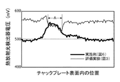
- 238000009529 body temperature measurement Methods 0.000 description 9
- 230000000052 comparative effect Effects 0.000 description 9
- 239000004065 semiconductor Substances 0.000 description 9
- 238000001514 detection method Methods 0.000 description 7
- 230000005540 biological transmission Effects 0.000 description 6
- 230000004048 modification Effects 0.000 description 5
- 238000012986 modification Methods 0.000 description 5
- XUIMIQQOPSSXEZ-UHFFFAOYSA-N Silicon Chemical compound [Si] XUIMIQQOPSSXEZ-UHFFFAOYSA-N 0.000 description 4
- 238000010586 diagram Methods 0.000 description 4
- 239000000463 material Substances 0.000 description 4
- 229910052710 silicon Inorganic materials 0.000 description 4
- 239000010703 silicon Substances 0.000 description 4
- 239000000919 ceramic Substances 0.000 description 3
- 230000000694 effects Effects 0.000 description 3
- 230000003287 optical effect Effects 0.000 description 3
- 230000002238 attenuated effect Effects 0.000 description 2
- 239000002019 doping agent Substances 0.000 description 2
- 238000000034 method Methods 0.000 description 2
- 230000009471 action Effects 0.000 description 1
- 230000004913 activation Effects 0.000 description 1
- 229910052782 aluminium Inorganic materials 0.000 description 1
- XAGFODPZIPBFFR-UHFFFAOYSA-N aluminium Chemical compound [Al] XAGFODPZIPBFFR-UHFFFAOYSA-N 0.000 description 1
- 230000008859 change Effects 0.000 description 1
- 230000002708 enhancing effect Effects 0.000 description 1
- 238000011156 evaluation Methods 0.000 description 1
- 238000002474 experimental method Methods 0.000 description 1
- 229910052751 metal Inorganic materials 0.000 description 1
- 239000002184 metal Substances 0.000 description 1
- 239000000203 mixture Substances 0.000 description 1
- 230000010355 oscillation Effects 0.000 description 1
Images


Landscapes
- Container, Conveyance, Adherence, Positioning, Of Wafer (AREA)
Description
アニール対象物と保持テーブルとの間に配置されて使用され、前記アニール対象物から放射されて前記保持テーブルに向かう熱放射光を減衰させる機能を持つチャックプレートであって、
前記アニール対象物が保持される上面は、前記アニール対象物が保持された状態で前記アニール対象物に接触する一様な領域と、前記アニール対象物と重なるが前記アニール対象物に接触しない非接触領域とを含み、
前記アニール対象物が保持される上面の前記非接触領域、及び前記保持テーブルの方を向く下面の少なくとも一方に、前記アニール対象物から放射されて前記保持テーブルに向かう熱放射光を吸収する色素を含む吸収膜が設けられているチャックプレートが提供される。
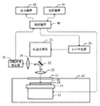
アニール対象物を保持する保持テーブルと、
前記保持テーブルと前記アニール対象物との間に配置されるチャックプレートと、
前記保持テーブルに保持された前記アニール対象物を加熱する加熱機構と、
前記保持テーブルに保持され、前記加熱機構によって加熱された前記アニール対象物からの熱放射光を検出する熱放射光検出器と
を有し、
前記チャックプレートの、前記アニール対象物が保持される上面は、前記アニール対象物が保持された状態で前記アニール対象物に接触する一様な領域と、前記アニール対象物と重なるが前記アニール対象物に接触しない非接触領域とを含み、
前記アニール対象物が保持される上面の前記非接触領域、及び前記保持テーブルの方を向く下面の少なくとも一方に、前記アニール対象物から放射されて前記保持テーブルに向かう熱放射光を吸収する色素が塗布されているアニール装置が提供される。
上記実施例では、吸収膜14B(図5A、図5B)として、黒色の色素を含む膜を用いたが、熱放射光検出器25(図1)で検出する対象となっている波長域の光を吸収または減衰させる材料を含む膜を用いてもよい。また、吸収膜14Bは、チャックプレート14の本体14Aの上面に設ける代わりに、下面に設けてもよいし、上面と下面との両方に設けてもよい。その他に、チャックプレート14を、熱放射光を減衰させる機能を持つ材料で形成してもよい。
11 レーザ透過窓
12 移動機構
13 保持テーブル
14 チャックプレート
14A チャックプレートの本体
14B 吸収膜
15 リフトピン用の穴
16 溝
17 リフトピン
18 リフトピン用貫通孔
19 吸着用貫通孔
20 レーザ光源
21 伝送光学系
22 ダイクロイックミラー
23、24 レンズ
25 熱放射光検出器
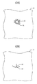
30 アニール対象物
31 高温になった箇所
32 貫通孔に対応する位置
40 制御装置
41 記憶装置
42 出力装置
Claims (3)
- アニール対象物と保持テーブルとの間に配置されて使用され、前記アニール対象物から放射されて前記保持テーブルに向かう熱放射光を減衰させる機能を持つチャックプレートであって、
前記アニール対象物が保持される上面は、前記アニール対象物が保持された状態で前記アニール対象物に接触する一様な領域と、前記アニール対象物と重なるが前記アニール対象物に接触しない非接触領域とを含み、
前記アニール対象物が保持される上面の前記非接触領域、及び前記保持テーブルの方を向く下面の少なくとも一方に、前記アニール対象物から放射されて前記保持テーブルに向かう熱放射光を吸収する色素を含む吸収膜が設けられているチャックプレート。 - アニール対象物を保持する保持テーブルと、
前記保持テーブルと前記アニール対象物との間に配置されるチャックプレートと、
前記保持テーブルに保持された前記アニール対象物を加熱する加熱機構と、
前記保持テーブルに保持され、前記加熱機構によって加熱された前記アニール対象物からの熱放射光を検出する熱放射光検出器と
を有し、
前記チャックプレートの、前記アニール対象物が保持される上面は、前記アニール対象物が保持された状態で前記アニール対象物に接触する一様な領域と、前記アニール対象物と重なるが前記アニール対象物に接触しない非接触領域とを含み、
前記チャックプレートの、前記アニール対象物が保持される上面の前記非接触領域、及び前記保持テーブルの方を向く下面の少なくとも一方に、前記アニール対象物から放射されて前記保持テーブルに向かう熱放射光を吸収する色素が塗布されているアニール装置。 - 前記チャックプレートは、前記熱放射光検出器によって検出される波長域の熱放射光を減衰させる請求項2に記載のアニール装置。
Priority Applications (6)
| Application Number | Priority Date | Filing Date | Title |
|---|---|---|---|
| JP2017240419A JP6976658B2 (ja) | 2017-12-15 | 2017-12-15 | チャックプレート及びアニール装置 |
| CN201880074747.8A CN111433892B (zh) | 2017-12-15 | 2018-11-16 | 卡盘板、退火装置及退火方法 |
| PCT/JP2018/042511 WO2019116826A1 (ja) | 2017-12-15 | 2018-11-16 | チャックプレート、アニール装置、及びアニール方法 |
| EP18887501.7A EP3726564B1 (en) | 2017-12-15 | 2018-11-16 | Chuck plate, annealing device, and annealing method |
| KR1020207014250A KR102337481B1 (ko) | 2017-12-15 | 2018-11-16 | 척플레이트, 어닐링장치, 및 어닐링방법 |
| US16/899,801 US11355344B2 (en) | 2017-12-15 | 2020-06-12 | Chuck plate, annealing device, and annealing method |
Applications Claiming Priority (1)
| Application Number | Priority Date | Filing Date | Title |
|---|---|---|---|
| JP2017240419A JP6976658B2 (ja) | 2017-12-15 | 2017-12-15 | チャックプレート及びアニール装置 |
Publications (2)
| Publication Number | Publication Date |
|---|---|
| JP2019110152A JP2019110152A (ja) | 2019-07-04 |
| JP6976658B2 true JP6976658B2 (ja) | 2021-12-08 |
Family
ID=67180115
Family Applications (1)
| Application Number | Title | Priority Date | Filing Date |
|---|---|---|---|
| JP2017240419A Active JP6976658B2 (ja) | 2017-12-15 | 2017-12-15 | チャックプレート及びアニール装置 |
Country Status (1)
| Country | Link |
|---|---|
| JP (1) | JP6976658B2 (ja) |
Families Citing this family (1)
| Publication number | Priority date | Publication date | Assignee | Title |
|---|---|---|---|---|
| KR102800186B1 (ko) * | 2019-12-17 | 2025-04-28 | 에스케이하이닉스 주식회사 | 온도 감지용 미러 장치 및 이를 포함하는 온도 감지 시스템 |
Family Cites Families (4)
| Publication number | Priority date | Publication date | Assignee | Title |
|---|---|---|---|---|
| JP2006140230A (ja) * | 2004-11-10 | 2006-06-01 | Sumitomo Heavy Ind Ltd | レーザ照射装置及びレーザ照射方法 |
| US7731798B2 (en) * | 2004-12-01 | 2010-06-08 | Ultratech, Inc. | Heated chuck for laser thermal processing |
| JP2006298607A (ja) * | 2005-04-22 | 2006-11-02 | Sumitomo Heavy Ind Ltd | 基板処理方法、基板搬送装置及び搬送装置 |
| JP5963701B2 (ja) * | 2013-03-27 | 2016-08-03 | 住友重機械工業株式会社 | 半導体アニール装置及び温度測定方法 |
-
2017
- 2017-12-15 JP JP2017240419A patent/JP6976658B2/ja active Active
Also Published As
| Publication number | Publication date |
|---|---|
| JP2019110152A (ja) | 2019-07-04 |
Similar Documents
| Publication | Publication Date | Title |
|---|---|---|
| US10739191B2 (en) | Determining a beam profile of a laser beam | |
| US20140314121A1 (en) | Optical non-destructive inspection apparatus and optical non-destructive inspection method | |
| EP2796858A1 (en) | Optical non-destructive inspection apparatus and optical non-destructive inspection method | |
| TW201843740A (zh) | 熱處理裝置、熱處理方法及半導體裝置的製造方法 | |
| US12106983B2 (en) | Annealing device and annealing method | |
| US11355344B2 (en) | Chuck plate, annealing device, and annealing method | |
| KR102039200B1 (ko) | 레이저 회절을 통해 3d 반도체 구조물의 온도를 측정하는 장치 및 방법 | |
| JP6976658B2 (ja) | チャックプレート及びアニール装置 | |
| US20100064783A1 (en) | Device for determining a mechanical property of a sample for investigation | |
| US20140321497A1 (en) | Optical non-destructive inspection apparatus and optical non-destructive inspection method | |
| US10591427B2 (en) | Analysis system and analysis method | |
| KR102231509B1 (ko) | 해석 장치 및 해석 방법 | |
| JP7505751B2 (ja) | 温度測定装置、温度測定方法、レーザ強度分布測定装置、レーザ強度分布測定方法、半導体回路評価装置及び半導体回路評価方法 | |
| CN109427626B (zh) | 激光退火装置及表面电阻计算装置 | |
| JP7051203B2 (ja) | アニール方法及びアニール装置 | |
| KR102258055B1 (ko) | 레이저 어닐링 장비의 온도 모니터링 시스템 | |
| JP2018132389A (ja) | ウエハ位置計測装置及びウエハ位置計測方法 | |
| JP7597792B2 (ja) | プロセスモニタ及びプロセスモニタ方法 | |
| KR100777570B1 (ko) | 급속열처리공정챔버의 오염측정장치 | |
| US20230071288A1 (en) | Method and apparatus for contactless measuring of an object surface | |
| JP2015230946A (ja) | 実装装置 |
Legal Events
| Date | Code | Title | Description |
|---|---|---|---|
| A621 | Written request for application examination |
Free format text: JAPANESE INTERMEDIATE CODE: A621 Effective date: 20200715 |
|
| A131 | Notification of reasons for refusal |
Free format text: JAPANESE INTERMEDIATE CODE: A131 Effective date: 20210803 |
|
| A521 | Request for written amendment filed |
Free format text: JAPANESE INTERMEDIATE CODE: A523 Effective date: 20210907 |
|
| TRDD | Decision of grant or rejection written | ||
| A01 | Written decision to grant a patent or to grant a registration (utility model) |
Free format text: JAPANESE INTERMEDIATE CODE: A01 Effective date: 20211109 |
|
| A61 | First payment of annual fees (during grant procedure) |
Free format text: JAPANESE INTERMEDIATE CODE: A61 Effective date: 20211109 |
|
| R150 | Certificate of patent or registration of utility model |
Ref document number: 6976658 Country of ref document: JP Free format text: JAPANESE INTERMEDIATE CODE: R150 |
|
| R157 | Certificate of patent or utility model (correction) |
Free format text: JAPANESE INTERMEDIATE CODE: R157 |