JP6972165B2 - Equipment and methods for additive manufacturing - Google Patents
Equipment and methods for additive manufacturing Download PDFInfo
- Publication number
- JP6972165B2 JP6972165B2 JP2019553311A JP2019553311A JP6972165B2 JP 6972165 B2 JP6972165 B2 JP 6972165B2 JP 2019553311 A JP2019553311 A JP 2019553311A JP 2019553311 A JP2019553311 A JP 2019553311A JP 6972165 B2 JP6972165 B2 JP 6972165B2
- Authority
- JP
- Japan
- Prior art keywords
- laser
- variable
- interferometer
- metal deposition
- distance
- Prior art date
- Legal status (The legal status is an assumption and is not a legal conclusion. Google has not performed a legal analysis and makes no representation as to the accuracy of the status listed.)
- Active
Links
Images


Classifications
-
- B—PERFORMING OPERATIONS; TRANSPORTING
- B23—MACHINE TOOLS; METAL-WORKING NOT OTHERWISE PROVIDED FOR
- B23K—SOLDERING OR UNSOLDERING; WELDING; CLADDING OR PLATING BY SOLDERING OR WELDING; CUTTING BY APPLYING HEAT LOCALLY, e.g. FLAME CUTTING; WORKING BY LASER BEAM
- B23K26/00—Working by laser beam, e.g. welding, cutting or boring
- B23K26/02—Positioning or observing the workpiece, e.g. with respect to the point of impact; Aligning, aiming or focusing the laser beam
- B23K26/03—Observing, e.g. monitoring, the workpiece
- B23K26/032—Observing, e.g. monitoring, the workpiece using optical means
-
- B—PERFORMING OPERATIONS; TRANSPORTING
- B22—CASTING; POWDER METALLURGY
- B22F—WORKING METALLIC POWDER; MANUFACTURE OF ARTICLES FROM METALLIC POWDER; MAKING METALLIC POWDER; APPARATUS OR DEVICES SPECIALLY ADAPTED FOR METALLIC POWDER
- B22F10/00—Additive manufacturing of workpieces or articles from metallic powder
- B22F10/20—Direct sintering or melting
- B22F10/25—Direct deposition of metal particles, e.g. direct metal deposition [DMD] or laser engineered net shaping [LENS]
-
- B—PERFORMING OPERATIONS; TRANSPORTING
- B22—CASTING; POWDER METALLURGY
- B22F—WORKING METALLIC POWDER; MANUFACTURE OF ARTICLES FROM METALLIC POWDER; MAKING METALLIC POWDER; APPARATUS OR DEVICES SPECIALLY ADAPTED FOR METALLIC POWDER
- B22F10/00—Additive manufacturing of workpieces or articles from metallic powder
- B22F10/30—Process control
-
- B—PERFORMING OPERATIONS; TRANSPORTING
- B22—CASTING; POWDER METALLURGY
- B22F—WORKING METALLIC POWDER; MANUFACTURE OF ARTICLES FROM METALLIC POWDER; MAKING METALLIC POWDER; APPARATUS OR DEVICES SPECIALLY ADAPTED FOR METALLIC POWDER
- B22F12/00—Apparatus or devices specially adapted for additive manufacturing; Auxiliary means for additive manufacturing; Combinations of additive manufacturing apparatus or devices with other processing apparatus or devices
- B22F12/50—Means for feeding of material, e.g. heads
- B22F12/53—Nozzles
-
- B—PERFORMING OPERATIONS; TRANSPORTING
- B22—CASTING; POWDER METALLURGY
- B22F—WORKING METALLIC POWDER; MANUFACTURE OF ARTICLES FROM METALLIC POWDER; MAKING METALLIC POWDER; APPARATUS OR DEVICES SPECIALLY ADAPTED FOR METALLIC POWDER
- B22F12/00—Apparatus or devices specially adapted for additive manufacturing; Auxiliary means for additive manufacturing; Combinations of additive manufacturing apparatus or devices with other processing apparatus or devices
- B22F12/90—Means for process control, e.g. cameras or sensors
-
- B—PERFORMING OPERATIONS; TRANSPORTING
- B23—MACHINE TOOLS; METAL-WORKING NOT OTHERWISE PROVIDED FOR
- B23K—SOLDERING OR UNSOLDERING; WELDING; CLADDING OR PLATING BY SOLDERING OR WELDING; CUTTING BY APPLYING HEAT LOCALLY, e.g. FLAME CUTTING; WORKING BY LASER BEAM
- B23K26/00—Working by laser beam, e.g. welding, cutting or boring
- B23K26/02—Positioning or observing the workpiece, e.g. with respect to the point of impact; Aligning, aiming or focusing the laser beam
- B23K26/03—Observing, e.g. monitoring, the workpiece
- B23K26/0344—Observing the speed of the workpiece
-
- B—PERFORMING OPERATIONS; TRANSPORTING
- B23—MACHINE TOOLS; METAL-WORKING NOT OTHERWISE PROVIDED FOR
- B23K—SOLDERING OR UNSOLDERING; WELDING; CLADDING OR PLATING BY SOLDERING OR WELDING; CUTTING BY APPLYING HEAT LOCALLY, e.g. FLAME CUTTING; WORKING BY LASER BEAM
- B23K26/00—Working by laser beam, e.g. welding, cutting or boring
- B23K26/02—Positioning or observing the workpiece, e.g. with respect to the point of impact; Aligning, aiming or focusing the laser beam
- B23K26/04—Automatically aligning, aiming or focusing the laser beam, e.g. using the back-scattered light
- B23K26/044—Seam tracking
-
- B—PERFORMING OPERATIONS; TRANSPORTING
- B23—MACHINE TOOLS; METAL-WORKING NOT OTHERWISE PROVIDED FOR
- B23K—SOLDERING OR UNSOLDERING; WELDING; CLADDING OR PLATING BY SOLDERING OR WELDING; CUTTING BY APPLYING HEAT LOCALLY, e.g. FLAME CUTTING; WORKING BY LASER BEAM
- B23K26/00—Working by laser beam, e.g. welding, cutting or boring
- B23K26/02—Positioning or observing the workpiece, e.g. with respect to the point of impact; Aligning, aiming or focusing the laser beam
- B23K26/04—Automatically aligning, aiming or focusing the laser beam, e.g. using the back-scattered light
- B23K26/046—Automatically focusing the laser beam
-
- B—PERFORMING OPERATIONS; TRANSPORTING
- B23—MACHINE TOOLS; METAL-WORKING NOT OTHERWISE PROVIDED FOR
- B23K—SOLDERING OR UNSOLDERING; WELDING; CLADDING OR PLATING BY SOLDERING OR WELDING; CUTTING BY APPLYING HEAT LOCALLY, e.g. FLAME CUTTING; WORKING BY LASER BEAM
- B23K26/00—Working by laser beam, e.g. welding, cutting or boring
- B23K26/14—Working by laser beam, e.g. welding, cutting or boring using a fluid stream, e.g. a jet of gas, in conjunction with the laser beam; Nozzles therefor
- B23K26/144—Working by laser beam, e.g. welding, cutting or boring using a fluid stream, e.g. a jet of gas, in conjunction with the laser beam; Nozzles therefor the fluid stream containing particles, e.g. powder
-
- B—PERFORMING OPERATIONS; TRANSPORTING
- B23—MACHINE TOOLS; METAL-WORKING NOT OTHERWISE PROVIDED FOR
- B23K—SOLDERING OR UNSOLDERING; WELDING; CLADDING OR PLATING BY SOLDERING OR WELDING; CUTTING BY APPLYING HEAT LOCALLY, e.g. FLAME CUTTING; WORKING BY LASER BEAM
- B23K26/00—Working by laser beam, e.g. welding, cutting or boring
- B23K26/14—Working by laser beam, e.g. welding, cutting or boring using a fluid stream, e.g. a jet of gas, in conjunction with the laser beam; Nozzles therefor
- B23K26/1462—Nozzles; Features related to nozzles
- B23K26/1464—Supply to, or discharge from, nozzles of media, e.g. gas, powder, wire
- B23K26/147—Features outside the nozzle for feeding the fluid stream towards the workpiece
-
- B—PERFORMING OPERATIONS; TRANSPORTING
- B23—MACHINE TOOLS; METAL-WORKING NOT OTHERWISE PROVIDED FOR
- B23K—SOLDERING OR UNSOLDERING; WELDING; CLADDING OR PLATING BY SOLDERING OR WELDING; CUTTING BY APPLYING HEAT LOCALLY, e.g. FLAME CUTTING; WORKING BY LASER BEAM
- B23K26/00—Working by laser beam, e.g. welding, cutting or boring
- B23K26/14—Working by laser beam, e.g. welding, cutting or boring using a fluid stream, e.g. a jet of gas, in conjunction with the laser beam; Nozzles therefor
- B23K26/1462—Nozzles; Features related to nozzles
- B23K26/1464—Supply to, or discharge from, nozzles of media, e.g. gas, powder, wire
- B23K26/1476—Features inside the nozzle for feeding the fluid stream through the nozzle
-
- B—PERFORMING OPERATIONS; TRANSPORTING
- B23—MACHINE TOOLS; METAL-WORKING NOT OTHERWISE PROVIDED FOR
- B23K—SOLDERING OR UNSOLDERING; WELDING; CLADDING OR PLATING BY SOLDERING OR WELDING; CUTTING BY APPLYING HEAT LOCALLY, e.g. FLAME CUTTING; WORKING BY LASER BEAM
- B23K26/00—Working by laser beam, e.g. welding, cutting or boring
- B23K26/34—Laser welding for purposes other than joining
- B23K26/342—Build-up welding
-
- B—PERFORMING OPERATIONS; TRANSPORTING
- B29—WORKING OF PLASTICS; WORKING OF SUBSTANCES IN A PLASTIC STATE IN GENERAL
- B29C—SHAPING OR JOINING OF PLASTICS; SHAPING OF MATERIAL IN A PLASTIC STATE, NOT OTHERWISE PROVIDED FOR; AFTER-TREATMENT OF THE SHAPED PRODUCTS, e.g. REPAIRING
- B29C64/00—Additive manufacturing, i.e. manufacturing of three-dimensional [3D] objects by additive deposition, additive agglomeration or additive layering, e.g. by 3D printing, stereolithography or selective laser sintering
- B29C64/10—Processes of additive manufacturing
- B29C64/141—Processes of additive manufacturing using only solid materials
- B29C64/153—Processes of additive manufacturing using only solid materials using layers of powder being selectively joined, e.g. by selective laser sintering or melting
-
- B—PERFORMING OPERATIONS; TRANSPORTING
- B29—WORKING OF PLASTICS; WORKING OF SUBSTANCES IN A PLASTIC STATE IN GENERAL
- B29C—SHAPING OR JOINING OF PLASTICS; SHAPING OF MATERIAL IN A PLASTIC STATE, NOT OTHERWISE PROVIDED FOR; AFTER-TREATMENT OF THE SHAPED PRODUCTS, e.g. REPAIRING
- B29C64/00—Additive manufacturing, i.e. manufacturing of three-dimensional [3D] objects by additive deposition, additive agglomeration or additive layering, e.g. by 3D printing, stereolithography or selective laser sintering
- B29C64/20—Apparatus for additive manufacturing; Details thereof or accessories therefor
- B29C64/205—Means for applying layers
- B29C64/209—Heads; Nozzles
-
- B—PERFORMING OPERATIONS; TRANSPORTING
- B29—WORKING OF PLASTICS; WORKING OF SUBSTANCES IN A PLASTIC STATE IN GENERAL
- B29C—SHAPING OR JOINING OF PLASTICS; SHAPING OF MATERIAL IN A PLASTIC STATE, NOT OTHERWISE PROVIDED FOR; AFTER-TREATMENT OF THE SHAPED PRODUCTS, e.g. REPAIRING
- B29C64/00—Additive manufacturing, i.e. manufacturing of three-dimensional [3D] objects by additive deposition, additive agglomeration or additive layering, e.g. by 3D printing, stereolithography or selective laser sintering
- B29C64/20—Apparatus for additive manufacturing; Details thereof or accessories therefor
- B29C64/264—Arrangements for irradiation
-
- B—PERFORMING OPERATIONS; TRANSPORTING
- B29—WORKING OF PLASTICS; WORKING OF SUBSTANCES IN A PLASTIC STATE IN GENERAL
- B29C—SHAPING OR JOINING OF PLASTICS; SHAPING OF MATERIAL IN A PLASTIC STATE, NOT OTHERWISE PROVIDED FOR; AFTER-TREATMENT OF THE SHAPED PRODUCTS, e.g. REPAIRING
- B29C64/00—Additive manufacturing, i.e. manufacturing of three-dimensional [3D] objects by additive deposition, additive agglomeration or additive layering, e.g. by 3D printing, stereolithography or selective laser sintering
- B29C64/30—Auxiliary operations or equipment
- B29C64/307—Handling of material to be used in additive manufacturing
- B29C64/343—Metering
-
- B—PERFORMING OPERATIONS; TRANSPORTING
- B29—WORKING OF PLASTICS; WORKING OF SUBSTANCES IN A PLASTIC STATE IN GENERAL
- B29C—SHAPING OR JOINING OF PLASTICS; SHAPING OF MATERIAL IN A PLASTIC STATE, NOT OTHERWISE PROVIDED FOR; AFTER-TREATMENT OF THE SHAPED PRODUCTS, e.g. REPAIRING
- B29C64/00—Additive manufacturing, i.e. manufacturing of three-dimensional [3D] objects by additive deposition, additive agglomeration or additive layering, e.g. by 3D printing, stereolithography or selective laser sintering
- B29C64/30—Auxiliary operations or equipment
- B29C64/386—Data acquisition or data processing for additive manufacturing
- B29C64/393—Data acquisition or data processing for additive manufacturing for controlling or regulating additive manufacturing processes
-
- B—PERFORMING OPERATIONS; TRANSPORTING
- B33—ADDITIVE MANUFACTURING TECHNOLOGY
- B33Y—ADDITIVE MANUFACTURING, i.e. MANUFACTURING OF THREE-DIMENSIONAL [3-D] OBJECTS BY ADDITIVE DEPOSITION, ADDITIVE AGGLOMERATION OR ADDITIVE LAYERING, e.g. BY 3-D PRINTING, STEREOLITHOGRAPHY OR SELECTIVE LASER SINTERING
- B33Y10/00—Processes of additive manufacturing
-
- B—PERFORMING OPERATIONS; TRANSPORTING
- B33—ADDITIVE MANUFACTURING TECHNOLOGY
- B33Y—ADDITIVE MANUFACTURING, i.e. MANUFACTURING OF THREE-DIMENSIONAL [3-D] OBJECTS BY ADDITIVE DEPOSITION, ADDITIVE AGGLOMERATION OR ADDITIVE LAYERING, e.g. BY 3-D PRINTING, STEREOLITHOGRAPHY OR SELECTIVE LASER SINTERING
- B33Y30/00—Apparatus for additive manufacturing; Details thereof or accessories therefor
-
- G—PHYSICS
- G01—MEASURING; TESTING
- G01B—MEASURING LENGTH, THICKNESS OR SIMILAR LINEAR DIMENSIONS; MEASURING ANGLES; MEASURING AREAS; MEASURING IRREGULARITIES OF SURFACES OR CONTOURS
- G01B11/00—Measuring arrangements characterised by the use of optical techniques
- G01B11/24—Measuring arrangements characterised by the use of optical techniques for measuring contours or curvatures
- G01B11/2441—Measuring arrangements characterised by the use of optical techniques for measuring contours or curvatures using interferometry
-
- B—PERFORMING OPERATIONS; TRANSPORTING
- B22—CASTING; POWDER METALLURGY
- B22F—WORKING METALLIC POWDER; MANUFACTURE OF ARTICLES FROM METALLIC POWDER; MAKING METALLIC POWDER; APPARATUS OR DEVICES SPECIALLY ADAPTED FOR METALLIC POWDER
- B22F2999/00—Aspects linked to processes or compositions used in powder metallurgy
-
- B—PERFORMING OPERATIONS; TRANSPORTING
- B23—MACHINE TOOLS; METAL-WORKING NOT OTHERWISE PROVIDED FOR
- B23K—SOLDERING OR UNSOLDERING; WELDING; CLADDING OR PLATING BY SOLDERING OR WELDING; CUTTING BY APPLYING HEAT LOCALLY, e.g. FLAME CUTTING; WORKING BY LASER BEAM
- B23K26/00—Working by laser beam, e.g. welding, cutting or boring
- B23K26/02—Positioning or observing the workpiece, e.g. with respect to the point of impact; Aligning, aiming or focusing the laser beam
- B23K26/03—Observing, e.g. monitoring, the workpiece
- B23K26/034—Observing the temperature of the workpiece
-
- B—PERFORMING OPERATIONS; TRANSPORTING
- B29—WORKING OF PLASTICS; WORKING OF SUBSTANCES IN A PLASTIC STATE IN GENERAL
- B29C—SHAPING OR JOINING OF PLASTICS; SHAPING OF MATERIAL IN A PLASTIC STATE, NOT OTHERWISE PROVIDED FOR; AFTER-TREATMENT OF THE SHAPED PRODUCTS, e.g. REPAIRING
- B29C64/00—Additive manufacturing, i.e. manufacturing of three-dimensional [3D] objects by additive deposition, additive agglomeration or additive layering, e.g. by 3D printing, stereolithography or selective laser sintering
- B29C64/10—Processes of additive manufacturing
- B29C64/106—Processes of additive manufacturing using only liquids or viscous materials, e.g. depositing a continuous bead of viscous material
- B29C64/124—Processes of additive manufacturing using only liquids or viscous materials, e.g. depositing a continuous bead of viscous material using layers of liquid which are selectively solidified
- B29C64/129—Processes of additive manufacturing using only liquids or viscous materials, e.g. depositing a continuous bead of viscous material using layers of liquid which are selectively solidified characterised by the energy source therefor, e.g. by global irradiation combined with a mask
- B29C64/135—Processes of additive manufacturing using only liquids or viscous materials, e.g. depositing a continuous bead of viscous material using layers of liquid which are selectively solidified characterised by the energy source therefor, e.g. by global irradiation combined with a mask the energy source being concentrated, e.g. scanning lasers or focused light sources
-
- B—PERFORMING OPERATIONS; TRANSPORTING
- B33—ADDITIVE MANUFACTURING TECHNOLOGY
- B33Y—ADDITIVE MANUFACTURING, i.e. MANUFACTURING OF THREE-DIMENSIONAL [3-D] OBJECTS BY ADDITIVE DEPOSITION, ADDITIVE AGGLOMERATION OR ADDITIVE LAYERING, e.g. BY 3-D PRINTING, STEREOLITHOGRAPHY OR SELECTIVE LASER SINTERING
- B33Y50/00—Data acquisition or data processing for additive manufacturing
- B33Y50/02—Data acquisition or data processing for additive manufacturing for controlling or regulating additive manufacturing processes
-
- Y—GENERAL TAGGING OF NEW TECHNOLOGICAL DEVELOPMENTS; GENERAL TAGGING OF CROSS-SECTIONAL TECHNOLOGIES SPANNING OVER SEVERAL SECTIONS OF THE IPC; TECHNICAL SUBJECTS COVERED BY FORMER USPC CROSS-REFERENCE ART COLLECTIONS [XRACs] AND DIGESTS
- Y02—TECHNOLOGIES OR APPLICATIONS FOR MITIGATION OR ADAPTATION AGAINST CLIMATE CHANGE
- Y02P—CLIMATE CHANGE MITIGATION TECHNOLOGIES IN THE PRODUCTION OR PROCESSING OF GOODS
- Y02P10/00—Technologies related to metal processing
- Y02P10/25—Process efficiency
Description
本開示は付加製造用の装置及び方法に関する。本開示は、特にレーザークラッディング(レーザー金属蒸着(LMD)用の装置及び方法に関する。 The present disclosure relates to devices and methods for additive manufacturing. The present disclosure relates specifically to devices and methods for laser cladding (laser metal deposition (LMD)).
レーザークラッディング(レーザー金属蒸着、LMD又はクラッディング)は、ワークピース上に材料を堆積するためにレーザービーム及び供給材料を使用する。レーザービームは、ワークピースの表面上に熔融溜り(Schmelzbad)を生成する。ノズルから金属粉末又は金属ワイヤが導入される。互いに溶接された材料領域が生成し、これは現存のワークピース上の構造又は新たな構造をもたらす。 Laser cladding (laser metal deposition, LMD or cladding) uses a laser beam and feed material to deposit the material on the workpiece. The laser beam creates a schmelzbad on the surface of the workpiece. Metal powder or metal wire is introduced from the nozzle. Material areas welded together are created, which results in structures on existing workpieces or new structures.
レーザー金属蒸着を用いて積層すること及び3次元の層構造を作り出すことは、知られている。一方、複雑な3次元の部品もレーザー金属蒸着を用いて製造されている。レーザー金属蒸着は、多数のプロセス変数の精密な調整を必要とし、この際、動作点の付近のプロセス変数の小さな領域においてのみ、満足できる製造を行なうことができる。これに対応して、現在、レーザー金属蒸着の際にプロセス変数を適切に調整することに対する高度な要求が生じている。 It is known to stack using laser metal deposition and to create a three-dimensional layered structure. On the other hand, complex three-dimensional parts are also manufactured using laser metal deposition. Laser metal deposition requires precise adjustment of a large number of process variables, in which satisfactory production can be achieved only in a small region of the process variables near the operating point. Correspondingly, there is now a high demand for proper adjustment of process variables during laser metal deposition.
プロセス制御及びプロセス監視用に、例えば溶接された又は堆積された材料領域について、相互作用領域又は熔融溜りからの輻射又はその幾何形状を検査するための測定技術を用いることができる。例えば熔融溜りの幾何形状解析用のカメラベースの方法又は温度測定用のパイロメータベースの方法のような公知の方法は、相互作用プロセスからの二次輻射に基づいており、絶対的な幾何形状に関して全く情報をもたらさないか又は非常に限定された情報しかもたらさない。付加製造された部品又は付加製造された溶接ビードの高さ及び/又は完全な幾何形状のデータは、加工品質を特徴づけるための及び/又はプロセス制御のための価値のある情報である。 For process control and process monitoring, measurement techniques can be used, for example, for welded or deposited material regions to inspect radiation from interaction regions or melt pools or their geometry. Known methods, such as camera-based methods for geometry analysis of melt pools or pyrometer-based methods for temperature measurement, are based on secondary radiation from the interaction process and with respect to absolute geometry. It does not provide any information or provides very limited information. Height and / or complete geometry data for additional manufactured parts or additional manufactured weld beads is valuable information for characterizing machining quality and / or for process control.
特許文献1からは、例えばガスタービン部品、例えばローター翼又はガイド翼、のような部品の製造用及び/又は修理用の方法が知られており、この方法では除去及び付加の処理ステップが組み合わされて1つのハイブリッド処理になっている。上記で示したパイロメータを使用したオンラインモニタリングによって、外形、温度、材料及び/又は表面状態のようなプロセス変数をチェックし、制御することができる。 From Patent Document 1, a method for manufacturing and / or repairing a part such as, for example, a gas turbine part, for example, a rotor blade or a guide blade, is known, in which a removal and addition processing step is combined. It is one hybrid process. Online monitoring using the pyrometer shown above can check and control process variables such as shape, temperature, material and / or surface condition.
本開示の課題は、付加製造用の装置及び方法を提供することであり、これらは改善されたプロセス制御、特にプロセス規制及び/又はプロセス、を提供する。特に、本発明の課題は、ワークピースに溶接された材料領域又は生成された構造の表面形状を確定することである。更に、本発明の課題は、レーザー金属蒸着用の改善された方法及び改善された製造装置を確立することであり、ここで、特に3次元部品の信頼性のある製造が可能となる。 An object of the present disclosure is to provide equipment and methods for additive manufacturing, which provide improved process control, in particular process regulation and / or process. In particular, an object of the present invention is to determine the surface shape of the material region welded to the workpiece or the resulting structure. Further, an object of the present invention is to establish an improved method and an improved manufacturing apparatus for laser metal deposition, which enables reliable manufacturing of particularly three-dimensional parts.
これらの課題は、独立請求項に記載の主題及び本発明の諸態様によって解決される。本発明の有利な実施形態は、下位請求項に示されている。 These problems are solved by the subject matter described in the independent claims and the aspects of the present invention. An advantageous embodiment of the present invention is set forth in the subclaims.
1つの態様によれば、付加製造用の装置が示される。この装置は、レーザービームを用いた材料加工用の、レーザービームをワークピースの加工領域に向けるように構成されている、レーザー装置、例えばレーザー加工ヘッド、と、供給材料を加工領域に供給するように構成されている、供給材料のための少なくとも1つの供給装置と、少なくとも1つの光学的測定ビームを用いてワークピースの表面、例えばこのワークピースまでの距離、又は本装置とこのワークピースの表面との間の距離、及び/又はこのワークピース表面の形状、を測定するように構成されている干渉計ユニットとを備えている。 According to one embodiment, an apparatus for addition manufacturing is shown. This device is configured to direct the laser beam to the machining area of the workpiece for material machining with a laser beam, such as a laser device, eg, a laser machining head, and to feed the feed material to the machining area. The surface of the workpiece, eg, the distance to the workpiece, or the surface of the instrument and the workpiece, using at least one feeder for the feed material and at least one optical measurement beam configured in. It comprises an interferometer unit configured to measure the distance between and / or the shape of the surface of the workpiece.
別の実施形態によれば、付加製造用の方法が示される。本方法は、ワークピースの加工領域にレーザービームを向けるステップと、加工領域へ供給材料を供給するステップと、干渉計ユニットを使用したこのワークピースの表面を測定する、例えば、このワークピースまでの距離及び/又はこのワークピース表面の形状を測定する、ステップとを備える。 According to another embodiment, a method for addition manufacturing is shown. The method measures the surface of the work piece using an interferometer unit, for example, up to this work piece, with the steps of directing the laser beam to the work area of the work piece, the step of supplying the feed material to the work area, and the interferometer unit. It comprises a step to measure the distance and / or the shape of the surface of this workpiece.
好ましい実施形態によれば、少なくとも1つの光学的測定ビームは、レーザービームに対して固定されて提供されていてよい。或いは、少なくとも1つの光学的測定ビームは、レーザービームに対し動的に、即ち、可動的に、提供されていてよい。換言すれば、この光学的測定ビームは、所定の走査動作を行ない又は走査図に沿って移動する。干渉計ユニットは、基準ビーム及び光学的測定ビームを提供するための干渉計を備えてよい。更に、この干渉計ユニットは、干渉計によって検出されたデータの評価用の評価ユニットを備えてよい。特に、この干渉計ユニットは、光学的測定ビームが、例えば特に直線的動作又は回転動作といった移動を、個別に又は組み合わせて行なえるように構成されている干渉計を備えてよい。この測定ビームによって行なわれる走査動作は、従って、円状又は直線状又は8の字形状であってもよい。直線状の走査動作は、加工方向に対して平行であってよく又はこれに対して角度を有していてよい。この光学的測定ビームは、先行して及び/又は後続して及び/又は熔融溜りを通って案内されてよい。2つ以上の光学的測定ビームは、互いに依存して又は互いに独立して移動することができる。一例では、例えば加工方向におけるレーザービームのビーム軸の回りに、2つ以上の測定ビームが一緒に回転動作を行なってよい。 According to a preferred embodiment, the at least one optical measurement beam may be provided fixed to the laser beam. Alternatively, at least one optical measurement beam may be provided dynamically, i.e., movably with respect to the laser beam. In other words, this optical measurement beam performs a predetermined scanning operation or moves along a scanning diagram. The interferometer unit may include an interferometer to provide a reference beam and an optical measurement beam. Further, the interferometer unit may include an evaluation unit for evaluating the data detected by the interferometer. In particular, the interferometer unit may comprise an interferometer configured such that the optical measurement beam can perform movements, such as linear or rotational movements, individually or in combination. The scanning operation performed by this measurement beam may therefore be circular, linear or figure eight. The linear scanning operation may be parallel to or angled with respect to the machining direction. This optical measurement beam may be guided in advance and / or subsequent and / or through a melt pool. Two or more optical measurement beams can move independently of each other or independently of each other. In one example, for example, two or more measurement beams may rotate together around the beam axis of the laser beam in the machining direction.
例えば、2つの光学的測定ビームが、1つが先行して、そして1つが後続して用いられてよい。この目的のため、光学的測定ビームが、2つの部分ビームに分割されていてよく、これらは同時に、先行して及び後続して案内されてよい。これらの部分ビームは、可動的に設けられていてよい。 For example, two optical measurement beams may be used, one preceded and one subsequently. For this purpose, the optical measurement beam may be split into two partial beams, which may be guided in advance and in succession at the same time. These partial beams may be movably provided.
少なくとも1つの光学的測定ビームは、以下の波長:1550nm、1310nm、1080nm、1030nm及び830nmの1つ以上を含んでよい。これらの波長は、光学的測定ビームに適した波長領域の中央波長であってよい。 The at least one optical measurement beam may include one or more of the following wavelengths: 1550 nm, 1310 nm, 1080 nm, 1030 nm and 830 nm. These wavelengths may be the middle wavelengths in the wavelength range suitable for the optical measurement beam.
好ましい実施形態においては、干渉計ユニットは、距離測定に基づいて、ワークピースの表面の位置及び/又はワークピースの表面形状を確定するように構成されていてよい。 In a preferred embodiment, the interferometer unit may be configured to determine the position of the surface of the workpiece and / or the surface shape of the workpiece based on distance measurements.
更に、干渉計ユニットは、ワークピースの加工領域までの距離及び/又はこの加工領域に隣接するこのワークピースの1つの領域までの距離を測定するように構成されていてよい。 Further, the interferometer unit may be configured to measure the distance to the machined area of the workpiece and / or the distance to one area of the workpiece adjacent to the machined area.
干渉計は、コヒーレンス干渉計又は低コヒーレンス干渉計を備えてよい。 The interferometer may include a coherence interferometer or a low coherence interferometer.
干渉計は、少なくとも1つの光学的測定ビームをレーザー装置のビーム経路にカップリングするように構成されていてよい。干渉計は、このレーザー装置のビーム経路から分離された、光学的測定ビームのためのビーム経路を備えてもよい。 The interferometer may be configured to couple at least one optical measurement beam to the beam path of the laser device. The interferometer may include a beam path for the optical measurement beam separated from the beam path of this laser device.
1つの実施例においては、少なくとも1つの供給装置が、供給材料として粉末又はワイヤを供給するように構成されていてよい。 In one embodiment, at least one feeder may be configured to feed powder or wire as a feed material.
少なくとも1つの供給装置は、環状ジェットパウダーノズル、多重ジェットパウダーノズル及び軸外パウダーノズルからなるグループから選択されていてよい。 The at least one feeder may be selected from the group consisting of annular jet powder nozzles, multiple jet powder nozzles and off-axis powder nozzles.
もう1つの実施例においては、少なくとも1つの光学的測定ビーム及びレーザービームが同軸に又は実質的に同軸になっていてよい。しかしながら、これに代えて又は追加して、光学的測定ビームは、レーザービームに対して又はレーザー装置の光軸に対して傾いていてもよい。 In another embodiment, the at least one optical measurement beam and the laser beam may be coaxial or substantially coaxial. However, instead or in addition, the optical measurement beam may be tilted with respect to the laser beam or with respect to the optical axis of the laser device.
干渉計は、少なくとも1つの光学的測定ビームをレーザービームに対して固定して提供するように構成されていてよい。これに代えて又は追加して、干渉計は、光学的測定ビームをレーザービームに対して可動的に提供するように構成されていてよい。 The interferometer may be configured to provide at least one optical measurement beam fixed to the laser beam. Alternatively or additionally, the interferometer may be configured to movably provide an optical measurement beam to the laser beam.
もう1つの実施例においては、レーザー装置及び/又は少なくとも1つの供給装置を、干渉計ユニットによって測定された距離に基づいて、制御する制御装置が設けられていてよい。 In another embodiment, a control device may be provided that controls the laser device and / or at least one supply device based on the distance measured by the interferometer unit.
例えば、この制御部は、ワークピースに対する装置の移動方向、ワークピースに対する移動速度、粉末流速、粉末量、粉末組成、粉末供給方向、ワイヤ供給方向、ワイヤ前進速度、作動距離、プロセスガス組成、プロセスガス圧、レーザー焦点直径、光軸の位置、レーザー焦点位置、レーザーパルス幅及びレーザー出力から選択した少なくとも1つのプロセス入力変数を調節するように、構成されていてよい。 For example, this control unit can be used for the moving direction of the device with respect to the workpiece, the moving speed with respect to the workpiece, the powder flow velocity, the powder amount, the powder composition, the powder supply direction, the wire supply direction, the wire forward speed, the working distance, the process gas composition, and the process. It may be configured to adjust at least one process input variable selected from gas pressure, laser focal diameter, optical axis position, laser focal position, laser pulse width and laser output.
本発明による装置は、レーザー金属蒸着ヘッドであってよく、又は、これを備える装置であってよい。 The apparatus according to the present invention may be a laser metal vapor deposition head, or may be an apparatus including the laser metal vapor deposition head.
本発明による装置は、レーザー金属蒸着(LMD)又はクラッディングのための方法用に構成されていてよい。本発明による方法は、レーザー金属蒸着(LMD)又はクラッディングのための方法を備えてよい。 The apparatus according to the invention may be configured for methods for laser metal deposition (LMD) or cladding. The method according to the invention may comprise a method for laser metal deposition (LMD) or cladding.
本装置は、付加製造の間に、即ち、レーザー金属蒸着の間に、製造プロセスの少なくとも1つの物理変数、例えば、ワークピース表面の位置及び/又は形状、及び/又はこのプロセスの間に製造される溶接ビード(部品とも呼ばれる)の幾何学的変数、及び/又はこれから派生する変数、及び/又は堆積された層の高さ、及び/又はこれから派生する変数を、距離測定から決定するように、構成されていてよい。その代わりに、1つ以上の追加的な物理変数、例えばレーザー出力、及び/又はレーザー焦点の寸法、及び/又は供給材料の供給速度、及び/又は供給材料の材料流量、及び/又はプロセスの間に生じる熔融溜りの寸法、即ち、直径、及び/又はこの熔融溜りの温度、及び/又は前述の変数の1つ以上から派生した変数等が検出されてもよい。この目的のため、対応する検出手段が設けられていてよい。 The device is manufactured during additional manufacturing, ie during laser metal deposition, during at least one physical variable of the manufacturing process, eg, the location and / or shape of the workpiece surface, and / or this process. To determine from distance measurements the geometric variables of the weld bead (also called the part) and / or the variables derived from it, and / or the height of the deposited layer and / or the variables derived from it. It may be configured. Instead, during one or more additional physical variables, such as the laser power and / or the dimensions of the laser focus, and / or the feed rate of the feed material, and / or the material flow rate of the feed material, and / or the process. The dimensions of the melt pool, i.e., the diameter, and / or the temperature of the melt pool, and / or variables derived from one or more of the aforementioned variables, etc. may be detected. Corresponding detection means may be provided for this purpose.
少なくとも1つの物理変数は、連続的に又は最大100ミリ秒、好ましくは最大20ミリ秒、の時間間隔で、好適には最大5ミリ秒の時間間隔で、有利には等時間間隔で検出又は特定されてよい。 At least one physical variable is detected or identified continuously or at time intervals of up to 100 ms, preferably up to 20 ms, preferably at time intervals of up to 5 ms, and preferably at equal time intervals. May be done.
更に、本装置は、少なくとも1つの特定された又は検出された物理変数及び/又はその変化に依存して、例えば焦点位置及び/又はレーザー出力等の、付加製造の少なくとも1つのプロセス変数を調整するように、構成されていてよい。 In addition, the device adjusts at least one process variable for additional manufacturing, such as focal position and / or laser power, depending on at least one identified or detected physical variable and / or its change. It may be configured as such.
この少なくとも1つのプロセス変数は、加工領域又は溶接ビードのモデルからのずれ及び/又は付加製造プロセスのモデルからのずれが最大閾値未満に維持され及び/又は極小とされるように、好ましくは1つの制御方法を用いて、調整されてよい。この目的のため、本装置は、調整装置及び/又は制御装置を備えてよく、これらは、モデルからのずれが最大閾値未満に維持されるように、そして好ましくは極小化されるように、少なくとも1つのプロセス変数を調整するように構成されている。 This at least one process variable is preferably one such that the deviation from the model of the machined area or weld bead and / or the deviation from the model of the additive manufacturing process is kept below the maximum threshold and / or minimized. It may be adjusted using a control method. For this purpose, the device may include adjustments and / or controls, at least such that deviations from the model are maintained below the maximum threshold and preferably minimized. It is configured to adjust one process variable.
本発明のもう1つの態様によれば、レーザーを用いた、部品の付加的レーザー金属蒸着の方法が提示され、この方法は、レーザー金属蒸着の間の溶接プロセスの少なくとも1つの物理変数を検出するステップと、この検出された少なくとも1つの物理変数及び/又はその変化に依存して、本方法の少なくとも1つのプロセス変数を設定するステップと、を備える。 According to another aspect of the invention, a method of additional laser metal deposition of parts using a laser is presented, which method detects at least one physical variable of the welding process during laser metal deposition. It comprises a step and a step of setting at least one process variable of the method depending on the detected at least one physical variable and / or its change.
付加的レーザー金属蒸着とは、本出願の範囲においては、好適にはレーザー金属蒸着を用いた好ましくは3次元の構造の付加製造のことを意味する。溶接プロセスなる用語は、好適には、このレーザー金属蒸着の工程を意味する。 The additional laser metal deposition, within the scope of the present application, preferably means the additional production of a three-dimensional structure using laser metal deposition. The term welding process preferably means this process of laser metal deposition.
本発明による方法を用いて、ずれやその他の障害の作用によるレーザー金属蒸着の物理変数の変化の際にも、部品を精密に製造することができる。本発明による方法によれば、部品の目標形状からのずれを小さくすることができる。その結果、物理変数の値又はその変化に基づいたプロセス変数の調整により、高い製造品質及び高いプロセス信頼性を達成することができる。 Using the method according to the invention, parts can be precisely manufactured even when the physical variables of laser metal deposition change due to the action of displacement or other obstacles. According to the method according to the present invention, the deviation of the component from the target shape can be reduced. As a result, high manufacturing quality and high process reliability can be achieved by adjusting process variables based on the values of physical variables or their changes.
特に、本発明による方法を用いて、レーザー金属蒸着により、3次元の層構造及び部品を製造することができ、ここでは、多数のプロセス変数を正確に適合させて調整することができるので、目的とする部品幾何形状を実現することができる。本発明による方法を用いて、もっと複雑な部品の付加製造も、産業用途に必要な信頼性のもとに、容易に実現することができる。 In particular, the method according to the invention can be used to produce three-dimensional layered structures and components by laser metal deposition, where a large number of process variables can be accurately adapted and adjusted. It is possible to realize the geometrical shape of the part. Using the method according to the present invention, additional manufacturing of more complicated parts can be easily realized with the reliability required for industrial applications.
好ましくは、本発明による方法における物理変数は、溶接プロセスの間に製造される部品の少なくとも1つの幾何形状変数及び/又はこれから派生した変数、及び/又はレーザー金属蒸着の際に堆積される層の高さ及び/又はこれから派生した変数である。特に好ましくは、本発明による方法における少なくとも1つの幾何形状変数は、レーザー金属蒸着用に使用され、部品に当てられるレーザーのビーム方向に向いた方向における部品又は層の高さである。好適には、レーザー金属蒸着用に加工ヘッドが使用される。有利には、この加工ヘッドにより、適切にはコヒーレンス断層撮影法を用いて、この加工ヘッドと部品との距離測定が可能となる。このようにして部品と加工ヘッドとの距離を非接触で測定することができる。有利には、基準位置、例えば部品の加工ヘッドに向いていない面の部位又は部品のこの面が当接する基板の部位等、に対する加工ヘッドの位置が分かっていれば、部品と加工ヘッドとの距離から、この加工ヘッドへの方向における部品の高さを容易に確定することができる。好適には、製造装置は、このような基準位置に対する加工ヘッドの相対位置を検出するように構成されている。 Preferably, the physical variables in the method according to the invention are at least one geometric variable and / or a variable derived from it, and / or a layer deposited during laser metal deposition during the welding process. Height and / or variables derived from it. Particularly preferably, at least one geometric variable in the method according to the invention is the height of the part or layer in the direction directed to the beam of the laser applied to the part used for laser metal deposition. Preferably, a machining head is used for laser metal deposition. Advantageously, the machining head allows the distance measurement between the machining head and the component, appropriately using coherence tomography. In this way, the distance between the component and the machining head can be measured in a non-contact manner. Advantageously, the distance between the part and the machining head if the position of the machining head with respect to a reference position, such as a portion of the surface of the component not facing the machining head or a portion of the substrate to which this surface of the component abuts, is known. Therefore, the height of the component in the direction to the processing head can be easily determined. Preferably, the manufacturing apparatus is configured to detect the relative position of the machining head with respect to such a reference position.
好ましくは、本発明の範囲においては、「部品の高さ」とは、レーザー金属蒸着の際の材料堆積の部位で現在達成されている高さを意味している。3D印刷で知られているように、本発明による付加レーザー金属蒸着用の方法では、部品は、好ましくは層状に製造され、ここで、複数の層が次々に続いて重なって取り付けられる。この目的のため、好ましくは、部品のCADモデルを用いて、CAMモデル(CAM=Computer Aided Manufacturing:コンピュータ支援製造)が生成され、これは、レーザー金属蒸着による、連続層の製造を可能とする。従って、この本発明の発展形態においては、部品の現在の高さは、先行する製造ステップにおいて既に達成された部品の高さ及び現在製造されている層の高さによって決定されている。結果的に、本発明による方法の実施形態では、好ましくは、部品の現在の高さ、又はそれに代えて若しくはそれに加えて、そしてまた好ましくは、現在堆積されている層の高さが少なくとも1つの物理的な変数として使用されてよい。 Preferably, within the scope of the invention, "component height" means the height currently achieved at the site of material deposition during laser metal deposition. As is known in 3D printing, in the method for additional laser metal deposition according to the present invention, the parts are preferably manufactured in layers, where a plurality of layers are attached one after the other in a stack. For this purpose, preferably the CAD model of the component is used to generate a CAM model (CAM = Computer Aided Manufacturing), which allows the production of continuous layers by laser metal deposition. Thus, in this evolution of the invention, the current height of the part is determined by the height of the part already achieved in the preceding manufacturing step and the height of the currently manufactured layer. As a result, in embodiments of the method according to the invention, preferably the current height of the component, or alternative or to it, and also preferably, the height of the currently deposited layer is at least one. It may be used as a physical variable.
本発明による方法では、本発明の有利な発展形態においては、レーザー金属蒸着用に供給装置、特に粉末輸送機、が溶接材料のために使用され、少なくとも1つの物理変数は、少なくとも、この溶接材料の供給流量又は材料流量、及び/又は供給装置の供給速度、及び/又は前述の変数の1つ以上から派生した変数である。好適には、本発明による方法では、付加レーザー金属蒸着用に加工ヘッドが使用され、ここで供給装置は、理想的にはこの加工ヘッド内に収容されている。有利には、供給装置の材料流量又は供給速度又は派生した変数は、加工ヘッド内で自動的に確定されるので、例えばセンサー等の検出手段をこの加工ヘッドの外側で使用する必要は全く無い。その結果、本発明による方法は、レーザー金属蒸着の際に典型的な起伏のある周囲条件においても、安定かつ信頼性良く実施することができる。 In the method according to the invention, in an advantageous development of the invention, a feeder for laser metal deposition, especially a powder transporter, is used for the weld material, and at least one physical variable is at least this weld material. Supply flow rate or material flow rate, and / or supply rate of the supply device, and / or a variable derived from one or more of the above-mentioned variables. Preferably, in the method according to the invention, a machining head is used for the additional laser metal deposition, where the feeder is ideally housed within the machining head. Advantageously, the material flow rate or feed rate of the feeder or derived variables are automatically determined within the machining head, so there is no need to use a detection means such as a sensor outside the machining head. As a result, the method according to the present invention can be stably and reliably carried out even under the undulating ambient conditions typical of laser metal deposition.
好適には、本発明による方法では、少なくとも1つの物理変数は、少なくとも、レーザーの出力及び/又はレーザーの焦点の寸法及び/又は前述の変数の1つ以上から派生した変数である。 Preferably, in the method according to the invention, at least one physical variable is at least a variable derived from the power of the laser and / or the dimensions of the focal point of the laser and / or one or more of the above-mentioned variables.
好ましくは、本発明による方法の発展例においては、レーザー金属蒸着は熔融溜りを用いて行なわれ、少なくとも1つの物理変数は、少なくとも、熔融溜りの寸法及び/又は熔融溜りの温度及び/又はこれらから派生した変数である。好適には、熔融溜りは、カメラ、特にCCDカメラ、を用いて撮像され、画像処理を用いて熔融溜りの少なくとも1つの寸法が確定される。レーザー金属蒸着用の加工ヘッドも使用されてよく、少なくとも1つの変数は、部品と加工ヘッドとの距離及び/又はこれから派生した変数であってよい。有利には、熔融溜りの寸法は、熔融溜りの温度と関係しており、熔融溜りの温度が高いほどこの熔融溜りの寸法が大きくなるようになっている。その結果、熔融溜りの少なくとも1つの寸法は、この熔融溜りの温度に対する尺度となる。 Preferably, in an evolution of the method according to the invention, laser metal deposition is performed using a melt pool and at least one physical variable is from at least the dimensions and / or the temperature of the melt pool and / or these. It is a derived variable. Preferably, the melt pool is imaged with a camera, particularly a CCD camera, and image processing is used to determine at least one dimension of the melt pool. A machining head for laser metal deposition may also be used, and the at least one variable may be the distance between the component and the machining head and / or a variable derived from it. Advantageously, the size of the melt pool is related to the temperature of the melt pool, and the higher the temperature of the melt pool, the larger the size of the melt pool. As a result, at least one dimension of the melt pool is a measure of the temperature of the melt pool.
好適には、本発明による方法では、少なくとも1つのプロセス変数は、部品に対するレーザーの焦点の位置及び/又はこの焦点の位置の時間的変化及び/又はこれらから派生した変数である。レーザーの焦点の位置及び/又はこの焦点の時間的変化を用いて、レーザー金属蒸着の際の堆積速度及び/又は空間的な堆積形状を容易に操作することができる。例えば、レーザー金属蒸着の際に、レーザーの焦点を合わせることにより又はレーザーの焦点をぼかすことにより、部品上に溶融材料が厚く又は空間的に不均一に堆積されやすくなる。その結果、本発明による方法によれば、堆積される層の高さ又は部品の特定の領域における特定の堆積速度を要求に合わせることができ、即ち、まさに製造すべき部品の事前に決定された幾何形状モデルに狙いを定めて、調整することができる。 Preferably, in the method according to the invention, at least one process variable is the position of the focal point of the laser with respect to the component and / or the temporal variation of the position of this focal point and / or the variable derived from them. The position of the focal point of the laser and / or the temporal variation of this focal point can be used to easily manipulate the deposition rate and / or spatial deposition shape during laser metal deposition. For example, during laser metal deposition, focusing the laser or defocusing the laser tends to cause thick or spatially non-uniform deposition of the molten material on the part. As a result, according to the method according to the invention, the height of the layer to be deposited or the specific deposition rate in a specific region of the component can be tailored to the requirement, i.e., the exact component to be manufactured is pre-determined. You can aim and adjust the geometry model.
好適には、本発明による方法では、少なくとも1つの変数が、継続的に、即ち、連続的に又は最大100ミリ秒、好ましくは最大20ミリ秒、そして好適には最大5ミリ秒、の時間間隔で、有利には等時間間隔で、検出される。このようにして、本発明による方法では、レーザー金属蒸着に十分な、少なくとも1つの変数の連続的なフィードバックが保証され、かくして、この少なくとも1つのプロセス変数は、十分に迅速に調整可能である。 Preferably, in the method according to the invention, at least one variable has a time interval of continuously, i.e. continuously or up to 100 ms, preferably up to 20 ms, and preferably up to 5 ms. Therefore, it is advantageously detected at equal time intervals. In this way, the method according to the invention guarantees continuous feedback of at least one variable sufficient for laser metal deposition, thus the at least one process variable can be adjusted quickly enough.
本発明の有利な発展例においては、本方法において、好ましくは1つの制御方法を用いて、少なくとも1つのプロセス変数が、部品及び/又はレーザー金属蒸着のモデルからのずれが最大閾値未満に維持され、及び/又は極小とされるように調整される。その結果、本発明による方法を用いて、部品を幾何形状的に高精度で製造することができる。とりわけ好ましくは、本発明による方法では、この部品は層状に製造される。好適には、少なくとも1つのプロセス変数が、部品の現在の高さが本発明による方法のプロセスモデルで予測される部品の現在の高さに対応するように、調整される。これに代えて又は追加して、そしてまた、とりわけ好ましくは、現在製造されている層は、レーザー金属蒸着のモデル、例えばレーザー金属蒸着のCAMモデル、から決定され、そして現在製造されている層の高さが、所定の限度未満に、即ち、ほぼ一定に維持される。 In a favorable development of the invention, in this method, preferably using one control method, at least one process variable is maintained with a deviation from the model of parts and / or laser metal deposition below the maximum threshold. , And / or adjusted to be minimal. As a result, the parts can be geometrically manufactured with high accuracy by using the method according to the present invention. Particularly preferably, in the method according to the invention, the parts are manufactured in layers. Preferably, at least one process variable is adjusted so that the current height of the part corresponds to the current height of the part predicted by the process model of the method according to the invention. Alternatively or additionally, and also more preferably, the currently manufactured layer is determined from a model of laser metal deposition, such as a CAM model of laser metal deposition, and of the currently manufactured layer. The height is kept below a predetermined limit, i.e., almost constant.
好ましくは、本発明による方法では、少なくとも1つの物理変数が制御変数となり、そして少なくとも1つのプロセス変数が調整変数となるような調節が行なわれる。好適には、本発明による方法では、物理的な変数は、部品の現在の高さ及び/又は現在レーザー金属蒸着で堆積されている層の高さである。 Preferably, in the method according to the invention, the adjustment is made so that at least one physical variable becomes a control variable and at least one process variable becomes a regulation variable. Preferably, in the method according to the invention, the physical variable is the current height of the part and / or the height of the layer currently deposited by laser metal deposition.
もう1つの態様においては、レーザーを用いた、部品の付加レーザー金属蒸着用の製造装置が提示され、この製造装置は、特に、付加レーザー金属蒸着のための本発明による方法を実行するために、上述したように構成されている。本発明による製造装置は、溶接プロセスの少なくとも1つの物理変数の検出用の少なくとも1つの検出手段、並びに検出された少なくとも1つの物理変数及び/又はその変化に依存する少なくとも1つのプロセス変数の調整用の少なくとも1つの作動手段を備える。この少なくとも1つのプロセス変数の調整の、検出された少なくとも1つの変数への、依存性は、好適には、本発明による製造装置の制御装置を用いて制御される。 In another embodiment, a manufacturing apparatus for additional laser metal deposition of parts using a laser is presented, wherein the manufacturing apparatus specifically performs the method according to the invention for additional laser metal deposition. It is configured as described above. The manufacturing apparatus according to the present invention is for at least one detection means for detecting at least one physical variable in the welding process, and for adjusting at least one process variable depending on the detected at least one physical variable and / or its change. It is provided with at least one operating means of. The dependence of this adjustment of at least one process variable on at least one detected variable is preferably controlled using the control device of the manufacturing apparatus according to the invention.
本発明の有利な発展例においては、製造装置は、レーザー金属蒸着用の加工ヘッド並びに加工ヘッドの部品からの距離の測定用に構成され及び/又はコヒーレンス断層撮影装置を備え又はこのような装置と光学的に結合されている距離検出装置を備える。このようにして部品からの加工ヘッドの距離を非接触で測定することができる。有利には、既に本発明による方法について上述したように、基準位置に対する加工ヘッドの位置が分かっていれば、部品と加工ヘッドとの距離から、加工ヘッドに向かう方向におけるこの部品の高さを容易に確定することができる。好適には、製造装置は、このような基準位置に対する加工ヘッドの相対位置を検出するように構成されている。 In an advantageous development of the present invention, the manufacturing apparatus is configured for measuring the machining head for laser metal deposition and the distance of the machining head from the component and / or is equipped with or with a coherence tomography device. It is equipped with an optically coupled distance detector. In this way, the distance of the machining head from the component can be measured non-contactly. Advantageously, as already described above for the method according to the invention, if the position of the machining head with respect to the reference position is known, the height of the part in the direction toward the machining head can be easily increased from the distance between the component and the machining head. Can be confirmed to. Preferably, the manufacturing apparatus is configured to detect the relative position of the machining head with respect to such a reference position.
本発明による製造装置は、好ましくは、レーザー金属蒸着用の粉末状溶接材料を供給するための供給装置並びに溶接材料の供給速度及び/又は材料流量を検出するための検出手段を備える。好適には、材料流量は、体積流量及び/又は質量流量として検出される。体積流量は、特に、画像生成手段によって容易に検出することができる。 The manufacturing apparatus according to the present invention preferably includes a supply device for supplying a powdered welding material for laser metal deposition and a detection means for detecting the supply speed and / or the material flow rate of the welding material. Preferably, the material flow rate is detected as a volume flow rate and / or a mass flow rate. Volumetric flow rates can be easily detected, in particular by image generation means.
本発明の有利な発展形態においては、製造装置は、レーザー金属蒸着の際に生じる熔融溜りの少なくとも1つの寸法を検出するための少なくとも1つの検出手段及び/又はこの熔融溜りの温度を検出するための少なくとも1つの検出手段及び/又はレーザーの出力を検出するための少なくとも1つの検出手段を、備える。有利には、レーザーの出力は、例えば、製造装置の好ましくは既存の、特にPCコントローラ又はCNCコントローラの形態の、制御装置によって検出可能な内部変数である。好適には、熔融溜りの温度を検出するための検出手段は、熔融溜りの少なくとも1つの寸法を検出するための検出手段を備える。これは、熔融溜りの寸法が熔融溜りの温度に依存していて、熔融溜りの温度が高いほどこの熔融溜りの寸法が大きくなるからである。好ましくは、少なくとも1つの寸法を検出するための検出手段は、熔融溜りの画像を取り込む少なくとも1つのCCDカメラを備える。この寸法は、例えば好適に設けられている評価装置を用いて決定されてよく、これから、例えば事前に決定されている較正データを用いて温度を確定することができる。 In an advantageous development of the present invention, the manufacturing apparatus is for detecting at least one detecting means for detecting at least one dimension of the melt pool generated during laser metal deposition and / or the temperature of the melt pool. At least one detection means and / or at least one detection means for detecting the output of the laser. Advantageously, the laser output is an internal variable detectable by the controller, for example, preferably in the form of a manufacturing device, preferably an existing one, particularly a PC controller or a CNC controller. Preferably, the detecting means for detecting the temperature of the melt pool comprises a detecting means for detecting at least one dimension of the melt pool. This is because the size of the melt pool depends on the temperature of the melt pool, and the higher the temperature of the melt pool, the larger the size of the melt pool. Preferably, the detecting means for detecting at least one dimension comprises at least one CCD camera that captures an image of the melt pool. This dimension may be determined, for example, using a suitablely provided evaluation device, from which the temperature can be determined, for example, using pre-determined calibration data.
好適には、本発明による製造装置では、少なくとも1つの作動手段は、レーザーの焦点の位置又はその変化の調整用の少なくとも1つの作動手段、及び/又はレーザーの出力の調整用の少なくとも1つの作動手段を備える。既述したように、レーザーの焦点を合わせることにより、空間的な材料堆積をとりわけ容易に操作することができる。好ましくは、作動手段は、部品に対して相対的に可動な、例えば1つのレベル面内で又は3次元的に可動な、製造装置の加工ヘッドである。 Preferably, in the manufacturing apparatus according to the invention, at least one actuating means is at least one actuating means for adjusting the position of the focal point of the laser or its change, and / or at least one actuating for adjusting the output of the laser. Provide means. As mentioned above, focusing the laser makes spatial material deposition particularly easy to manipulate. Preferably, the actuating means is a machining head of a manufacturing apparatus that is relatively mobile relative to the component, eg, movable in one level plane or three-dimensionally.
好適には本発明による製造装置は、調整装置及び/又は制御装置を備えており、これらは、少なくとも1つのプロセス変数を調整して、レーザー金属蒸着用の部品のモデルからのずれ又はプロセスモデルからのずれが最大閾値未満に維持されるように、好ましくは極小化されるように、構成されている。その結果、本発明のこの発展形態においては、部品の予定される幾何形状設計の少なくとも一部が本発明による方法の制御変数となっている。 Preferably, the manufacturing apparatus according to the invention comprises an adjusting device and / or a controlling device, which adjusts at least one process variable to deviate from the model of the part for laser metal deposition or from the process model. The deviation is configured to be kept below the maximum threshold and preferably minimized. As a result, in this evolution of the invention, at least part of the planned geometry design of the part is a control variable for the method according to the invention.
好ましくは、製造装置は制御部を備え、この制御部では、少なくとも1つの物理変数が制御変数となっており、少なくとも1つのプロセス変数が調整変数となっている。 Preferably, the manufacturing apparatus includes a control unit, in which at least one physical variable is a control variable and at least one process variable is a control variable.
上記の実施形態の態様は、所望により互いに組み合わせることができることは、おのずから、明らかである。好適な、任意で選択される本開示の実施形態及び特別な態様が、従属請求項、図面及び本願の記載で示される。 It is self-evident that the embodiments of the above embodiments can be combined with each other if desired. Suitable, optionally selected embodiments and special embodiments of the present disclosure are set forth in the dependent claims, drawings and description of the present application.
本発明は、レーザービーム及び供給材料(「供給材料」又は「追加材料」ともいう。)を用いた付加製造の監視及び/又は制御を提供する。使用されているセンサー原理は、距離測定用の干渉法であり、例えば光学的な低コヒーレンス干渉法(Kurzkohaerenz−Interferometrie)である。この干渉法は、例えば製造される表面の位置の決定用に、プロセスに先行して、及び/又は、結果として生じた堆積された材料の表面形状の測定用に後続して使用されてよい。 The present invention provides monitoring and / or control of addition manufacturing using a laser beam and feed material (also referred to as "feed material" or "additional material"). The sensor principle used is an interferometry for distance measurement, eg, an optical low coherence interferometry (Kurzkohaerens-Interferometry). This interferometry may be used prior to the process and / or subsequently for measuring the surface shape of the resulting deposited material, for example for determining the location of the surface to be manufactured.
以上により、本発明は、オンラインの(又はその場での)、幾何形状測定の形態でのプロセス結果を正確に検査するためのセンサー技術を提供し、この結果、改善されたプロセス管理、特に改善されたプロセス制御及び/又はプロセス調整を達成することができる。 As described above, the present invention provides a sensor technique for accurately inspecting process results in the form of online (or in-situ) geometry measurement, resulting in improved process control, especially improvements. Process control and / or process coordination made can be achieved.
本開示の実施例が図に示され、以下に詳細に説明される。 Examples of the present disclosure are shown in the figures and are described in detail below.
以下では、特に明記しない限り、同じ素子及び同じ作用を有する素子には同じ参照番号が用いられている。 In the following, unless otherwise specified, the same reference number is used for the same element and the element having the same operation.
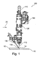
図1は、本開示の実施形態による固定された光学的測定ビームを有する、付加製造用の装置100又は付加レーザー金属蒸着用の製造装置の概略図を示す。装置100は、レーザー金属蒸着ヘッドであってよい。
FIG. 1 shows a schematic diagram of an
付加製造用装置100は、加工ビーム又はレーザービーム112を用いる材料加工用のレーザー装置110(例えばレーザー加工ヘッド)であって、レーザービーム112をワークピース10の加工領域に向けるように構成されているレーザー装置110;供給材料を加工領域に供給するように構成された供給材料用の少なくとも1つの供給装置130;及び、干渉計140を有する干渉計ユニットであって、少なくとも1つの光学的測定ビームによりワークピース10からの距離を測定するように構成されている干渉計ユニットを備えている。装置100は、実施形態によれば、加工方向20に沿って可動であってよい。加工方向20は、ワークピース10に関する装置100の移動方向であってよい。特に、この加工方向は水平方向であってよい。
The
本発明によれば、例えば低コヒーレンス干渉計等の干渉計が、距離測定用に用いられる。例えば、この干渉法は、加工すべきワークピースの表面の位置の決定のためのLMDプロセスに先行して、及び/又は、結果として生じる堆積された材料の表面形状の測定用に後続して、使用されてよい。これにより、幾何形状測定の形態でのプロセス結果の正確な計測用のオンラインセンサー技術が提供され、その結果、改善されたプロセス管理及び/又はプロセス制御若しくはプロセス調整を達成することができる。 According to the present invention, an interferometer such as a low coherence interferometer is used for distance measurement. For example, this interferometry precedes the LMD process for determining the position of the surface of the workpiece to be machined and / or for the measurement of the surface shape of the resulting deposited material. May be used. This provides online sensor technology for accurate measurement of process results in the form of geometry measurements, which can result in improved process control and / or process control or process coordination.
図1に例示的に示されているように、干渉計140は、光学的測定ビームをレーザービームに対して実質的に固定して提供するように構成されていてよい。しかしながら、本開示は、これに限定されるものでなく、干渉計140は、例えば図2、4A、4B、6A、6B及び7に示されているように、光学的測定ビームをレーザービーム112に対して動的に、即ち、可動的に提供するように構成されていてよい。
As exemplified in FIG. 1, the
装置100は、実施形態によれば、レーザー金属蒸着(LMD)用に用いられてよく、このレーザー金属蒸着では、ワークピース10上に材料を堆積するためにレーザービーム112及び供給材料が使用される。図1に示されているように、レーザービーム112は、ワークピース10の表面上に熔融溜り14を生成する。例えばノズル132等の供給装置130を用いて、供給材料(これは例えば金属粉末であってよい)が、この熔融溜り14に導入される。相互に溶接した材料領域が生成され、この材料領域は、現在対象となっているワークピースに、例えば溶接ビード12のような構造をもたらす。同様に、装置100は、いわゆる高速堆積溶接(High−Speed Cladding)に使用されてよく、この高速堆積溶接では、熔融溜りは全く生成されず、むしろ融解された粉末がワークピース表面に当たり、そしてこのワークピース表面上に堆積される。
装置100、特にレーザー装置110、は、ワークピース10上にレーザービーム112を集束するための集束光学系120を備えてよい。集束光学系120は、1つの光軸を規定する。例えば、集束光学系120は固定された焦点距離又は可変な焦点距離(ズーム)を有する光学系であってよい。集束光学系120は、光軸を規定する少なくとも1つの結像光学素子を備える。例えば、レーザー装置110の光ファイバーから出射される、発散するレーザー光束が、コリメータ光学系により、平行なレーザー光束に変換され、この平行なレーザー光束は集束レンズによってワークピース10上に集束される。
The
干渉計ユニットは、光学的測定ビーム(これはレーザービームであってよい)を用いて、例えば干渉計140によって規定される基準点に関して、ワークピース10からの距離を測定するように、構成されている。干渉計140は、コヒーレンス干渉計、特に低コヒーレンス干渉計、であってよい。干渉計を用いた距離測定は公知であり、詳細には説明しない。特に、干渉計140は、装置100が加工方向20に沿って移動される際に、及び/又は測定ビームがワークピースの表面上を移動される際に、距離の変化を測定するように、構成されていてよい。例えば、これによって表面形状測定を行なうことができる。
The interferometer unit is configured to use an optical measurement beam, which may be a laser beam, to measure the distance from the
本明細書で記述されている他の実施形態と組み合わせることができる実施形態によれば、干渉計ユニットは、加工領域からの距離を測定するように、構成されている。例えば、堆積溶接ビードのような、本装置によって加工された領域の幾何形状の決定のために、表面形状測定が後続して実施されてよい。この表面形状測定は、実施形態によれば、誤差検出及び/又は1つ以上のプロセス入力変数の制御のために用いられてよい。例えば、プロセス入力変数は、粉末流量、ワイヤ送り量、プロセス速度、レーザー出力、ワーキングディスタンスなどであってよい。 According to embodiments that can be combined with other embodiments described herein, the interferometer unit is configured to measure distance from the machining area. Surface geometry measurements may be subsequently performed to determine the geometry of the region machined by the device, such as a deposited weld bead. This surface shape measurement may be used for error detection and / or control of one or more process input variables, according to embodiments. For example, the process input variables may be powder flow rate, wire feed rate, process speed, laser output, working distance, and the like.
いくつかの実施形態においては、干渉計ユニットは、加工領域に隣接しているワークピース10の1つの領域からの距離を測定するように、構成されていてよい。この領域は、このワークピース10の未加工の表面であってよい。例えば、表面形状測定(例えばワークピース表面のz位置)が、基準測定として及び/又はプロセス実行用に、先行して用いられてよい。
In some embodiments, the interferometer unit may be configured to measure the distance from one area of the
本開示のセンサーシステムは、例えば低コヒーレンス干渉法等の干渉法に基づいている。この目的のため、干渉計から測定ビームが、軸を外れて、固定的に又は可動的に提供される。或いは、この干渉計から提供される測定ビームは、加工レーザーの光学的なビーム経路にカップリングされ、同軸に又はほぼ同軸に相互作用ゾーンの中へ、固定的に又は可動的に集束される。 The sensor system of the present disclosure is based on an interferometry such as a low coherence interferometry. For this purpose, the measuring beam from the interferometer is provided off-axis, fixedly or movably. Alternatively, the measurement beam provided by this interferometer is coupled to the optical beam path of the processing laser and is coaxially or nearly coaxially focused into the interaction zone, either fixedly or movably.
いくつかの実施形態においては、干渉計140は、レーザー装置110のビーム経路から分離された光学的測定ビームのためのビーム経路を備えていてよい。いくつかの実施形態においては、干渉計140は、光学的測定ビームをレーザー装置110の光軸に対して傾けて又は角度をつけて、ワークピース10に向けるように、構成されていてよい。例えば干渉計140は、レーザー装置110のビーム経路から分離された光学的測定ビーム用の軸外ビーム経路を備えてよく、ここで光学的測定ビームの斜め入射が例えば後続して行なわれてよい。堆積溶接ビードの高さの測定が行なわれてよく、ここで干渉計140は、固定されて後続して配置されていてよい。更なる実施形態においては、表面形状の測定が、例えば1次元又は2次元の振動動作を用いて後続して行なわれてよい。更なる実施形態によれば、干渉計140は、光学的測定ビームをレーザー装置110のビーム経路にカップリングするように、構成されていてよい。光学的測定ビームは、レーザービーム112に対して実質的に同軸であってよい。いくつかの実施形態においては、少なくとも1つの供給装置130が、粉末ジェットを供給材料として放出するように構成されている。
In some embodiments, the
距離測定は、干渉計ユニットによって、固定された又は可動的な光学的測定ビームを用いて、例えば加工レーザー若しくはレーザービーム112の周りを回転する測定ビーム又はレーザー装置の光軸に対して任意に偏向された測定ビームを用いて、行なわれてよい。これにより、堆積溶接ビードの高さを測定することができ、ここで干渉計又は光学的測定ビームは、後続して固定されて(例えば加工方向20に沿った単一方向で)配置されていてよい。更なる実施形態においては、例えば基材及び/又は堆積の高さの、先行領域及び/又は後続領域での測定が(例えば固定配置され、加工方向20に沿った単一方向で)行なわれてよい。或いは、(例えばスキャナを回転して、多方向で)表面形状の測定が行なわれてよい。所望により、粉末密度(粉末流による光学的測定ビームの「乱れ」)の測定が行なわれてよい。
Distance measurements are arbitrarily deflected by an interferometer unit using a fixed or movable optical measurement beam, eg, a measurement beam rotating around a processed laser or
ここで記述されている他の実施形態と組み合わせることができる実施形態によれば、装置100は、更に、制御部を備え、この制御部は、干渉計によって測定された距離に基づいて、レーザー装置110及び/又は少なくとも1つの供給装置130を調整及び/又は制御するように構成されている。この調整は、先行して及び/又は後続して実施される干渉法に基づいて行なわれてよい。
According to embodiments that can be combined with other embodiments described herein, the
典型的には、プロセス管理及び/又はプロセス実行は、干渉計によって測定された距離に基づいて行なわれてよい。例えば、加工速度、レーザー出力、レーザー焦点、及び/又は、粉末流量又はワイヤ送り量のような供給装置の操作変数は、干渉法に基づいて制御又は設定されてよい。これに代えて又は追加して、干渉法は、装置で加工された領域、例えば堆積溶接ビード、の品質管理用に、実施されてよい。 Typically, process control and / or process execution may be based on the distance measured by the interferometer. For example, the operating variables of the feeder such as machining speed, laser power, laser focus, and / or powder flow rate or wire feed rate may be controlled or set based on interferometry. Alternatively or additionally, interferometry may be performed for quality control of the machined area of the device, eg, a deposited weld bead.
ここで記述されている他の実施形態と組み合わせることができる実施形態によれば、少なくとも1つの供給装置130は、環状ジェット粉末ノズル、多重ジェット粉末ノズル、及び軸外粉末ノズルからなる群から選択されていてよい。図1には、例示的に、軸外粉末ノズル132(「横型粉末ノズル」とも呼ばれる。)が示されている。軸外粉末ノズル132は、軽量で、簡単で堅牢なシステムであり、特に、到達しづらい溶接位置においても良好なアクセス性を特徴としている。
According to embodiments that can be combined with other embodiments described herein, the at least one
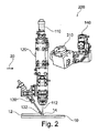
図2は、本開示の実施形態による、例えば回転する光学的測定ビームのような、可動光学的測定ビームを有する付加製造用の装置200を概略的に示す。
FIG. 2 schematically illustrates an
いくつかの実施形態においては、干渉計140は、光学的測定ビームをレーザービーム112に対して可動的に又は動的に提供するように、構成されていてよい。特に干渉計140は、光学測定ビームをレーザービーム112の周りに回転させるように、構成されていてよい。光学的測定ビームは、ワークピース10上で、2次元の輪郭、例えば円形の輪郭、を走査してよい。これにより、例えば堆積溶接ビードの表面形状測定を行なうことができる。
In some embodiments, the
装置200及び特に干渉計140は、駆動部210を備えていてよく、この駆動部は光学的測定ビームをワークピース上を移動又は走査させるように構成されている。典型的には、干渉計140は、光学的測定ビームをワークピース10に向けるための、この光学的測定ビームを偏向させる例えばレンズや、ミラー又はウェッジプレート等の、1つ以上の光学素子を備える。これらの1つ以上の光学素子の少なくとも1つの光学素子は、光学的測定ビームをワークピース10上を移動又は走査させるように、可動であってよい。或いは、この駆動部は、機械的な駆動部、例えば回転駆動部、であってよく、この駆動部は、光学的測定ビームをワークピース10上を移動又は走査させるように、干渉計140を駆動する。
The
図3A及び3Bは、それぞれ、本開示の実施形態による固定された光学的測定ビーム142を有する、付加製造用の装置300及びビーム経路の概略図である。
3A and 3B are schematic views of an
装置300は、環状ジェット粉末ノズル330を備える。特に、この環状ジェット粉末ノズル330は、粉末ジェットを供給材料として出射するように構成されていてよい。光学的測定ビーム142は、レーザービーム112に対して実質的に同軸であるか又は傾斜していてよい。粉末ジェット134は、環状ジェット粉末ノズル330の外側の第1の点又は第1の領域に向けられていてよく、この第1の点又は第1の領域は、ワークピースの加工領域上に又はこの加工領域の上方にあってよい。レーザービーム112は、環状ジェット粉末ノズル330の外側の第2の点(例えば焦点)又は第2の領域に向けられていてよく、この第2の点又は第2の領域は、ワークピースの加工領域にあってよい。
The
第1の点及び第2の点は、重なっていてもよく又は互いに離間していてよい。図3Bの例に示すように、第1の点又は第1の領域は、環状ジェット粉末ノズル330の出口及び/又は集束光学系120の出口の約20mm外側(例えば下側)に配置されていてよい。第2の点又は第2の領域は、環状ジェット粉末ノズル330の出口及び/又は集束光学系120の出口の約23.5mm外側(例えば下側)に配置されていてよい。これらの数値は、単に例示的なものであり、図3Bに示された実施形態をこれらに限定するものではない。第1の点及び第2の点は、垂直方向で上下に並べて配置されていてよい。光学的測定ビーム142は、ワークピースの点又は領域に向けられていてよく、この点又は領域は、上記の第1の点及び/又は第2の点に対し水平方向でずれている。
The first point and the second point may overlap or may be separated from each other. As shown in the example of FIG. 3B, the first point or region is located approximately 20 mm outside (eg, lower) of the outlet of the annular
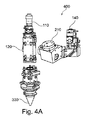
図4A及び4Bは、それぞれ、本開示の実施形態による可動な、例えば回転する、光学的測定ビームを有する、付加製造用の装置400及びビーム経路の概略図を示す。
4A and 4B show schematics of an
装置400は、図3A及び3Bを参照して説明したような、環状ジェット粉末ノズル330を備える。この光学的測定ビームは、動的、即ち空間的に可動、である。特に、この光学的測定ビームは、レーザービーム112及び/又は集束光学系120の光軸の周りを回転することができる、この光学的測定ビームは、ワークピース10上で、2次元の輪郭242、例えば円形の輪郭、を走査してよい。これにより、例えば堆積溶接ビードの表面形状測定を行なうことができる。光学的測定ビーム142は、レーザービーム112に対して実質的に同軸であるか又は傾斜していてよい。
The
図5A及び5Bは、それぞれ、本開示の更なる実施形態による固定された光学的測定ビーム142を有する、付加製造用の装置500及びビーム経路の概略図を示す。
5A and 5B show schematics of an
装置500は、多重ジェット粉末ノズル530を備える。多重ジェット粉末ノズル530は、少なくとも2つの粉末ノズル532を備えてよく、これらのノズルは、それぞれ、粉末ジェットをワークピース上の加工領域に供給するように構成されていてよい。典型的には、この多重ジェット粉末ノズル530は、4つの粉末ノズル532を備え、これらは互いに対して或る角度で配置されている。
The
図5Bに示されているように、少なくとも2つの粉末ノズル532の粉末ジェット134は、多重ジェット粉末ノズル530の外側の第1の点又は第1の領域に向けられていてよく、この第1の点又は第1の領域は、ワークピースの加工領域上に又はこの加工領域の上方にあってよい。レーザービーム112は、多重ジェット粉末ノズル530の外側の第2の点(例えば焦点)又は第2の領域に向けられていてよく、この第2の点又は第2の領域は、加工領域上にあってよい。光学的測定ビーム142は、レーザービーム112に対して実質的に同軸であるか又は傾斜していてよい。
As shown in FIG. 5B, the
この第1の点及びこの第2の点は、重なっていてよく、又は互いに離間していてよい。図5Bの例に示すように、第1の点又は第1の領域は、多重ジェット粉末ノズル530の出口及び/又は集束光学系120の出口の約14mm外側(例えば下側)に配置されていてよい。第2の点又は第2の領域は、更に約0.8mm外側に、即ち、多重ジェット粉末ノズル530の出口及び/又は集束光学系120の出口の約14.8mm外側(例えば下側)に、配置されていてよい。これらの数値は、単に例示的なものであり、図5Bに示された実施形態をこれらに限定するものではない。第1の点及び第2の点は、垂直方向で上下に並べて配置されていてよい。光学的測定ビーム142は、ワークピースの点又は領域に向けられていてよく、この点又は領域は、上記の第1の点及び/又は第2の点に対し水平方向でずれている。
The first point and the second point may overlap or may be separated from each other. As shown in the example of FIG. 5B, the first point or region is located approximately 14 mm outside (eg, lower) of the outlet of the multiple
図6A及び6Bは、それぞれ、本開示の更なる実施形態による、回転する光学的測定ビームを有する付加製造用の装置600及びビーム経路の概略図を示す。
6A and 6B show schematics of an
装置600は、図5A及び5Bを参照して説明したような、多重ジェット粉末ノズル530を備える。光学的測定ビームは、動的、即ち、空間的に可動である。例えば、光学的測定ビームは、レーザービーム112及び/又は集束光学系120の光軸の周りを回転することができるか又はこれらに対して偏向して照射することができる。この光学的測定ビームは、ワークピース10上で、2次元の輪郭、例えば円形の輪郭、を走査してよい。これにより例えば堆積溶接ビードの表面形状測定を行なうことができる。光学的測定ビーム142は、レーザービーム112に対して実質的に同軸であるか又は傾斜していてよい。
The
図7は、本開示の更なる実施形態による、付加製造用の装置700の概略図を示す。装置700はワイヤを用いた堆積溶接用に構成されていてよい。
FIG. 7 shows a schematic diagram of an
ここで記述されている他の実施形態と組み合わせることができる実施形態によれば、少なくとも1つの供給装置730は、ワイヤ731を供給材料として放出するように構成されている。このワイヤ731は、例えば金属ワイヤであってよい。
According to embodiments that can be combined with other embodiments described herein, the at least one
光学的測定ビーム742は、レーザービームに対して軸を外れて又は実質的に同軸で、提供されてよい。分離されたビーム経路で提供される(例えば後続して斜め入射する)軸外測定ビームを用いて、表面形状の測定が行なわれてよく、例えば1次元又は2次元の振動動作を用いて後続する領域で行なわれてよい。同軸ビームの構成では、堆積溶接ビードの高さの測定が行なわれてよく、ここで干渉計740が後続領域に固定されて(例えば加工方向に沿った単一方向で)位置決めされてよい。更に、動的又は可動的構成の場合には、表面形状の測定は、例えば回転可能に軸支された少なくとも2つのウェッジプレート744を使用しつつ(多方向で)行なわれてよい。ここでは光学的測定ビーム742は、2つのウェッジプレート744によって2つの部分ビームに分割される。その結果、例えば、これらの部分ビームのそれぞれ1つが先行して1つが後続して移動され、こうして両方の領域における表面形状が同時に検出される。
The
図8は、本開示の実施形態による、付加製造の方法800のフロー図である。本方法は、ここに記載された付加製造用の装置を使用して実行されてよい。
FIG. 8 is a flow chart of the
本方法は、ステップ810において、レーザービームをワークピースの加工領域へ向けることとこの加工領域への供給材料を供給することとを含む。本方法は、更にステップ820において、干渉計を備える干渉計ユニットを使用したワークピースからの距離を測定することを含む。
The method comprises directing the laser beam to a machining area of the workpiece and supplying feed material to this machining area in
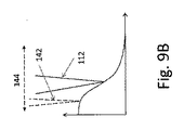
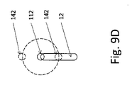
図9Aには、光学的測定ビーム142の直線的走査図144が示されている。ここでは、光学的測定ビーム142は、先行した領域の位置と後続する領域の位置との間を前後に、即ち、加工方向に対して平行に、移動され、このプロセスにおいて、溶接ビード12の幾何形状又はプロファイルが検出される。この直線的走査動作144の測定結果が図9Bに示されている。図9Bは、加工点又はレーザービーム112の直前及び直後での、加工方向に沿った溶接ビード12の高さプロファイルを示す。図9C及び9Dは、代わりの走査動作144を示し、図9Cにおいては、光学的測定ビーム142は、例えば加工点又はレーザービーム112の周りを円形に案内され、こうして先行領域及び後続領域において、(連続して)測定が行なわれる。図9Dにおいては、2つの光学的測定ビームが一緒に、加工点又はレーザービーム112の周りで円形に沿ってガイドされ、こうして先行領域及び後続領域において同時に測定が行なわれる。更に、溶接ビード12の側面の表面形状が、この走査図に沿って検出されてよい。この走査図又は走査動作144は、加工方向に沿って移動することができる。
FIG. 9A shows a
本発明の実施形態においては、光学的測定ビーム142は、以下の中央波長:1550nm、1310nm、1080nm、1030nm及び830nmの少なくとも1つを備えてよい。
In an embodiment of the invention, the
図10に示す、本発明による付加レーザー金属蒸着の方法1010は、3D印刷法であり、これを用いて溶接ビード又は部品1020が、図11及び12に示された、本発明による付加製造用の装置又は製造装置1035のレーザー1030を用いたレーザー金属蒸着を用いて、製造される。
The
本方法では、目的とする部品高が、部品1020のCADモデルから導出され、部品1020の製造用のCAMモデルに基づいて、レーザー金属蒸着を用いた層の堆積用の層の高さ1040が決定される。この層の高さ1040は、本発明による方法1010の制御変数となっている。
In this method, the target component height is derived from the CAD model of the
この制御変数は、コントローラ1050に転送され、このコントローラは、目的とする層高1040からレーザー金属蒸着用の一組のプロセス変数1060を決定し、これらのプロセス変数は本発明による方法1010の調整変数として用いられる。ここに示された実施例においては、これらのプロセス変数1060は、レーザー1030の光1065の出力、レーザー1030の焦点の位置、及び本発明による製造装置1035のプロセスヘッド1090のノズル1080を通る粉末状の溶接材料1070の材料流量を含む。
This control variable is transferred to the
このプロセス変数のセット1060を用いて、レーザー金属蒸着1095により、部品1020が、溶接される。層の実際の高さ1096は、レーザー金属蒸着1095で生じ、この高さは、部品1020とプロセスヘッド1090のノズル1080との距離によって確定される。この確定は、光学的な干渉断層撮影装置1097を用いて行なわれ、この装置を用いて、この干渉断層撮影装置の光源2110の測定光2100が、レーザー金属蒸着1095において部品1020の製造に用いられるレーザー1030のビーム経路2115に、プロセスヘッド1090内で、カップリングされる。この際、レーザー1030の光及び測定光2100は、部分透過ミラー2117を用いて、それぞれ、レーザー1030の光1065の下向きの方向ではノズル1080に向かって一緒にガイドされ、レーザー1030の光1065の照射上向きの方向ではノズル1080から分離される。このレーザー1030の光及び測定光2100は、スペクトル的に一致しておらず、こうしてこの測定光2100は、このレーザー1030の光の成分によって殆んど妨害されずに分析することができる。レーザー金属蒸着の際に起こる、光源2110の測定光2100の反射は、プロセスヘッド1090内のビーム経路2115へ戻る。このプロセスヘッド1090内で、この反射はデカップリングされ、そして干渉法により、もともとプロセスヘッド1090に投入された光源2110の測定光2100と比較される。この比較から上記の距離が得られる。干渉断層撮影装置1097及びプロセスヘッド1090内に含まれる光学的ビーム経路2115は、このビーム経路2115に存在する光学素子を含め、協働して1つの距離センサーを形成する。この距離センサー自体は公知であり、そしてこれはここで説明した溶接プロセスとは別の、特にレーザー溶接用の、Precitec GmbH社のIn−Process−Depth−Meterの溶接プロセスとして知られているレーザー溶接で公知となっており、独国特許出願公開第10102014011569A1号明細書に記載されている。
Using this set of
この距離センサーを利用するには、得られた距離信号のフィルタリングが必要である。というのも、レーザー溶接法における距離センサーの公知の上述の利用とは異なり、レーザー金属蒸着への距離センサーの利用には、ノズル1080から出て部品1020上に堆積され、距離センサーの光学的信号の一部を遮断する粉末状の溶接材料1070の影響を考慮する必要があるからである。というのも、この溶接材料1070は、干渉断層撮影装置1097の光源2110の測定光2100の大部分を吸収するからである。従って、距離信号のフィルタリングは、本発明による方法の堅牢性を保証するものである。
In order to utilize this distance sensor, it is necessary to filter the obtained distance signal. This is because, unlike the known above-mentioned use of distance sensors in laser welding, the use of distance sensors for laser metal deposition involves exiting
フィルタリング用には、まず、ここでは20ミリ秒の時間ウィンドウ、更に、特に図示しない実施例においては4ミリ秒の時間ウィンドウ、に亘って、全部の検出された距離値が記録される。続いて、これらの検出された距離値からフィルタ値が決定され、このフィルタ値が時間的に連続する同じ20ミリ秒(又は更なる実施例においては4ミリ秒)の持続時間を有する時間ウィンドウに適用される。レーザー1030が停止している場合は、片側の散乱のみが起こるので、ここでは最大値フィルタが使用され、この最大値フィルタは、測定された最も大きな距離値を実際の距離に対する基準として除外する。1つの時間ウィンドウにおける測定された距離値の分析により両側の散乱が起こることが示されると、大部分の測定データを集約する距離値が考慮される、即ち、測定データは、距離値の分布における最頻値により、即ち、「モードフィルタ」により、フィルタリングされる。このフィルタリングは、測定データの最も高い密度を有する距離値が熔融溜りからの距離を信頼性良く示すという事実を考慮している。
For filtering, first, all detected distance values are recorded over a time window of 20 ms here, and a time window of 4 ms in particular examples not shown. Subsequently, a filter value is determined from these detected distance values into a time window in which the filter values have a duration of the same 20 ms (or 4 ms in a further embodiment) that are temporally continuous. Applies. Since only one-sided scattering occurs when the
レーザー金属蒸着を用いて堆積された層の実際の高さ1096が、このようにして得られた距離から、得られる。
The
本発明による方法では、レーザー金属蒸着の更に他の物理変数が検出されてよい。こうして、レーザー金属蒸着の際に生成される熔融溜り2140の温度が追加的に決定されてよい。この目的のため、熔融溜り2140は、例えば製造装置1035のCCDカメラ2150を用いて観察される。熔融溜り2140の観察用に、熔融溜り2140からノズル1080を通って加工ヘッド1090の光学的ビーム経路2115に到達した光の一部が部分透過ミラー2145を用いてデカップリングされ、CCDカメラ2150に結像される。CCDカメラ2150は、製造装置1035の分析装置2155に接続されている。分析装置2155は、アルゴリズムによって、CCDカメラ2150によって取り込まれた熔融溜り2140の画像を分析し、この熔融溜り2140の平均直径を決定する。分析装置2155は、較正データを受け取り、この較正データを用いて熔融溜り2140の平均直径からこの熔融溜り2140の温度が推定される。
In the method according to the invention, yet other physical variables of laser metal deposition may be detected. In this way, the temperature of the
CCDカメラ2150及び分析装置2155は、加工ヘッド1090内に一体的に取り扱い可能に収納されており、即ち、この加工ヘッド1090と一緒に、一体的に取り扱い可能であり、こうして加工ヘッド1090及びそのハウジング(図11、12及び13には図示されていない。)は、レーザー金属蒸着の際の過酷なプロセス条件から、CCDカメラ2150及び分析装置2155を信頼性よく保護する。
The
追加的に、ノズル1080を通る粉末状の溶接材料1070の一定に維持された材料流量が検出されてよい。この材料流量は長い遅延時間を有し、素早いプロセスフィードバックを制限するので、この材料流量は一定に維持される。加工ヘッド1090内の粉末供給ライン2165における粉末センサー2160は、溶接材料1070の実際の材料流量を観察し、これを体積流量として検出する。この体積流量の検出は、プロセス変数1060の調整によって、溶接材料1070の体積流量の変化に基づく製造プロセスの調整を可能とする。図示された実施例に使用されている粉末センサー2160は、光学的な流量計であって、この流量計は、(詳細には図示されていない)粉末輸送機の出口の断面のうち、粉末状の溶接材料1070によって占められる面積の割合を確定する。この粉末輸送機は、ノズル1080へ溶接材料1070を供給するために加工ヘッド1090に配置されており、こうしてこの溶接材料1070は、レーザー金属蒸着用に公知のようにノズル1080に到達し、部品1020に堆積されることができる。
Additionally, a constant material flow rate of the powdered
ここで、体積流量の2次関数は、粉末輸送機の出口の断面のうち、粉末状の溶接材料1070によって占められる面積の割合に比例する。ここで、レーザー金属蒸着1095の際に部品1020の目的とする幾何形状を正確に実現するように、溶接材料1070の体積流量がコントローラ1050によって考慮される。
Here, the quadratic function of the volumetric flow rate is proportional to the ratio of the area occupied by the
図示された実施例においては、コントローラ1050は、PCシステムとして実現されている。これに代えて又は追加して、コントローラ1050は、図示された実施例以外に対応する更なる実施例においては、CNCコントローラとして実装されていてよい。追加的な外部のハードウェア及びソフトウェアの制御装置は、この更なる実施例においては不要である。この際、プロセスセンサーが高速バスインタフェースを用いてこのCNCコントローラに接続されている。
In the illustrated embodiment, the
上述の検出された物理変数、即ち、層の実際の高さ1096、熔融溜り2140の温度及び/又は溶接材料1070の体積流量に依存して、コントローラ1050は、レーザー金属蒸着1095用のプロセス変数1060の調整されたセットを確定する。これらのプロセス変数は、レーザー金属蒸着1095を用いて製造された部品1020の幾何形状のばらつきを極小とするように調整され、こうして起こり得るばらつきが、設定された許容誤差閾値未満となるようにされる。この結果、部品1020は、高信頼性かつ堅牢に製造される。
Depending on the detected physical variables described above, i.e. the actual height of the
ここで記述されている他の実施形態と組み合わせることができる実施形態によれば、上記の供給材料は粉末又はワイヤである。特に、本方法はレーザー金属蒸着(LMD)のための方法であってよい。 According to embodiments that can be combined with other embodiments described herein, the feed material is powder or wire. In particular, this method may be a method for laser metal deposition (LMD).
本開示によれば、レーザーに基づいた(粉末又はワイヤを用いる)付加製造は、加工レーザーとワークピースとの間の相互作用ゾーン内又はその周囲における幾何形状的な距離及び/又は表面形状の測定に基づくプロセスモニター及び/又はプロセス実行用の(固定又は動的に偏向する)干渉法に基づくセンサー技術と組み合わされて提供されている。 According to the present disclosure, laser-based additive manufacturing (using powder or wire) measures the geometric distance and / or surface shape within or around the interferometric zone between the processed laser and the workpiece. It is provided in combination with interferometry-based sensor technology for process monitoring and / or process execution (fixed or dynamically deflected) based on.
例えば、光学的測定ビームは、レーザー金属蒸着ヘッドを通り、粉末流(粉末堆積溶接)を貫通するか又はワイヤの付近を通過して、固定して照射されるか又は正確にかつ極めて動的に移動され、こうして測定作業を連続して又は並行して実施することができる。測定作業は、基準測定としての又はプロセス実行用の、先行領域での表面形状測定(ワークピース表面のz位置)であってよい。また別の測定作業は、堆積された溶接ビードの幾何形状の決定用の、例えば不具合検出用の、後続する領域での表面形状測定であってよい。これらの測定結果は、プロセス入力変数(例えばレーザー出力、粉末流量、ワイヤ送り量、プロセス速度)の制御用に使用されてよい。
For example, the optical measurement beam passes through a laser metal deposition head, through a powder stream (powder deposition welding), or near a wire, and is fixedly irradiated or accurately and extremely dynamically. It is moved so that the measurement work can be performed continuously or in parallel. The measurement operation may be surface shape measurement (z position on the workpiece surface) in the preceding region, either as a reference measurement or for process execution. Yet another measurement task may be surface geometry measurement in subsequent regions for determining the geometry of the deposited weld beads, eg, for defect detection. These measurements may be used to control process input variables (eg laser power, powder flow rate, wire feed rate, process speed).
Claims (18)
レーザービーム(112)による材料加工のためのレーザー装置(110)であって、前記レーザービーム(112)をワークピース(10)の加工領域上に向けるように構成されているレーザー装置(110);
供給材料のための少なくとも1つの供給装置(130)であって、前記供給材料を前記加工領域に供給するように構成されている供給装置;及び
干渉計(140)を備えた干渉計ユニットであって、少なくとも1つの光学的測定ビーム(142)により前記ワークピース(10)の表面までの距離を測定するように構成されている干渉計ユニット
を備えていることを特徴とする付加製造用の装置。 A device (100) for additive manufacturing.
A laser device (110) for processing a material with a laser beam (112), the laser device (110) configured to direct the laser beam (112) onto the machined area of the workpiece (10);
At least one feeder (130) for the feed material, the feeder unit configured to feed the feed material to the machining area; and an interferometer unit comprising an interferometer (140). An apparatus for additional manufacturing comprising an interferometer unit configured to measure the distance to the surface of the workpiece (10) by at least one optical measuring beam (142). ..
前記追加の物理変数が、前記供給材料の供給流量、前記供給装置の供給速度、レーザー出力、前記レーザービーム(112)の焦点直径、熔融溜りの寸法及び前記熔融溜りの温度から選択されることを特徴とする装置。 The apparatus (100) according to any one of claims 1 to 3 , further comprising a detection means for detecting at least one additional physical variable.
The additional physical variables are selected from the feed flow rate of the feed material, the feed rate of the feed device, the laser output, the focal diameter of the laser beam (112), the dimensions of the melt pool and the temperature of the melt pool. apparatus shall be the feature.
溶接プロセスの少なくとも1つの物理変数(1096)の検出のための検出手段(1097)並びに、前記少なくとも1つの検出された物理変数(1060)及び/又はその変化の関数として、少なくとも1つのプロセスパラメータ(1060)を調整するための作動手段を備え、
レーザー金属蒸着用の加工ヘッド(1090)並びに距離検出装置(10097)を備え、前記距離検出装置は、前記部品(1020)からの前記加工ヘッド(1090)の距離の測定用に構成されており、及び/又は前記距離検出装置は、干渉断層撮影装置(1097)を備えるか又は干渉断層撮影装置と光学的に結合されている、
部品(1020)の付加レーザー金属蒸着(1095)用の装置(1035)であることを特徴とする装置。 A device according to any one of請Motomeko 1-4,
Soluble detecting means for detecting at least one physical variable of the contact process (1096) (1097) and, as a function of the at least one detected physical variables (1060) and / or its change, at least one process parameter Provided with an actuating means for adjusting (1060)
Comprising a Le Za machining head for metal deposition (1090) as well as the distance detection device (10097), the distance detecting device is configured for measuring the distance of the machining head from the component (1020) (1090) And / or the distance detection device is equipped with an interference tomography device (1097) or is optically coupled to the interference tomography device.
An apparatus (1035) for additional laser metal deposition (1095) of a component (1020) .
前記装置が、前記干渉計ユニットによって測定された距離に基づいて、及び/又は前記少なくとも1つの決定された物理変数に基づいて、及び/又は前記少なくとも1つの検出された物理変数に基づいて、前記レーザー装置(110)及び/又は前記少なくとも1つの供給装置(130)を制御するように構成されている制御部を備えることを特徴とする装置。 The device (100) according to any one of claims 1 to 5.
The device is said to be based on the distance measured by the interferometer unit and / or based on the at least one determined physical variable and / or based on the at least one detected physical variable. A device comprising a control unit configured to control a laser device (110) and / or the at least one supply device (130).
前記制御部が、少なくとも1つのプロセス入力変数を制御することによって、前記レーザー装置(110)及び/又は前記少なくとも1つの供給装置(130)を制御するように、構成されており、
ここで、前記プロセス入力変数は、前記ワークピース(10)に対する前記装置の移動方向、前記ワークピース(10)に対する移動速度、前記供給装置(130)の供給速度、前記供給材料の供給流量、粉末流速、粉末量、粉末組成、粉末供給方向、ワイヤ供給方向、ワイヤ送り速度、ワーキングディスタンス、プロセスガス組成、プロセスガス圧、レーザー焦点直径、光軸の位置、レーザー焦点位置、レーザーパルス幅、及びレーザー出力から選択される、
ことを特徴とする装置。 The device (100) according to claim 6.
The control unit is configured to control the laser apparatus (110) and / or the at least one supply apparatus (130) by controlling at least one process input variable.
Here, the process input variables are the moving direction of the device with respect to the work piece (10), the moving speed with respect to the work piece (10), the supply speed of the supply device (130), the supply flow rate of the supply material, and the powder. Flow velocity, powder volume, powder composition, powder supply direction, wire supply direction, wire feed rate, working distance, process gas composition, process gas pressure, laser focal diameter, optical axis position, laser focal position, laser pulse width, and laser. Selected from output,
A device characterized by that.
前記制御部が、前記加工領域又は前記溶接ビード(12)又は前記付加製造プロセスのモデルからのずれが最大閾値未満に維持され及び/又は極小となるように、少なくとも1つのプロセス変数を調整するように、構成されていることを特徴とする装置。 The device (100) according to claim 6 or 7.
The control unit adjusts at least one process variable such that the deviation from the machined area or the weld bead (12) or the model of the additive manufacturing process is maintained below the maximum threshold and / or minimizes. A device characterized by being configured.
前記干渉計(140)が、コヒーレンス干渉計又は低コヒーレンス干渉計であり、
及び/又は
前記干渉計(140)が、前記レーザー装置(110)のビーム経路に前記光学的測定ビーム(142)をカップリングするように構成されており、又は
前記干渉計(140)が、前記光学的測定ビーム(142)のための、前記レーザー装置(110)の前記ビーム経路から分離された、ビーム経路を備える、
ことを特徴とする装置。 The device (100) according to any one of claims 1 to 8.
The interferometer (140) is a coherence interferometer or a low coherence interferometer.
And / or the interferometer (140) is configured to couple the optical measurement beam (142) to the beam path of the laser device (110), or the interferometer (140) is said. A beam path for the optical measurement beam (142), separated from the beam path of the laser device (110).
A device characterized by that.
前記干渉計(140)が、前記光学的測定ビーム(142)を前記レーザービーム(112)に対して固定して提供するように構成されており、及び/又は、
前記干渉計(140)が、前記光学的測定ビーム(142)を前記レーザービーム(112)に対して可動的に提供するように構成されており、及び/又は、
前記干渉計が、前記少なくとも1つの光学的測定ビーム(142)を、先行領域での1つの位置と後続領域での1つの位置との間で、直線的又は円軌道で前後に移動させるように構成されている、
ことを特徴とする装置。 The device (100) according to any one of claims 1 to 9.
The interferometer (140) is configured to provide the optical measurement beam (142) fixedly to the laser beam (112) and / or.
The interferometer (140) is configured to movably provide the optical measurement beam (142) to the laser beam (112) and / or.
The interferometer is such that the at least one optical measurement beam (142) is moved back and forth in a linear or circular orbit between one position in the preceding region and one position in the succeeding region. It is configured,
A device characterized by that.
前記光学的測定ビーム(142)の波長領域の少なくとも1つの中央波長が、1,550nm、1,310nm、1,080nm、1,030nm及び/又は830nmであることを特徴とする装置。 The device according to any one of claims 1 to 10.
Wherein at least one central wavelength of the wavelength region of the optical measuring beam (142), 1, 550nm, 1,310nm, 1,080nm , and wherein the a 1,030nm and / or 830 nm.
前記少なくとも1つの供給装置(130,730)が、供給材料として粉末又はワイヤ(731)を供給するように構成されており、及び/又は、環状ジェット粉末ノズル(330)、多重ジェット粉末ノズル(530)及び軸外粉末ノズルからなるグループから選択されることを特徴とする装置。 The device (100) according to any one of claims 1 to 11.
The at least one feeder (130,730) is configured to feed powder or wire (731) as a feed material and / or an annular jet powder nozzle (330), a multiple jet powder nozzle (530). ) And a device selected from the group consisting of off-axis powder nozzles.
前記装置(100)が、レーザー金属蒸着ヘッドであることを特徴とする装置。 The device (100) according to any one of claims 1 to 12.
The device (100) is a device characterized by being a laser metal vapor deposition head.
前記レーザー金属蒸着の間に溶接プロセスの少なくとも1つの物理変数(1096)が検出され、検出された該少なくとも1つの物理変数(1096)及び/又はその変化に依存して、前記方法の少なくとも1つのプロセス変数(1060)が調整されることを特徴とする方法。 Using the apparatus according to any one of請Motomeko 1-13, a method for adding a laser metal deposition part (1020),
At least one physical variable (1096) of the welding process was detected during the laser metal deposition, and depending on the detected at least one physical variable (1096) and / or its change, at least one of the methods. A method characterized in that the process variable (1060) is adjusted.
前記物理的な変数(1096)が、少なくとも、前記溶接プロセスの間に製造された部品(1020)の幾何形状変数(1096)及び/又はこれから派生した変数及び/又は前記レーザー金属蒸着の間に堆積された層の高さ及び/又はこれから派生した変数であることを特徴とする方法。 The method according to claim 14.
The physical variables (1096) are deposited at least during the geometry variables (1096) and / or derived variables of the part (1020) manufactured during the welding process and / or the laser metal deposition. A method characterized by being a layer height and / or a variable derived from it.
レーザー金属蒸着のために、溶接材料用の供給装置(2165)が使用され、
前記少なくとも1つの物理変数は、少なくとも、当該供給装置(2165)の供給流量及び/又は供給速度及び/又は前述の変数の1つ以上から派生した変数であり、
及び/又は
前記少なくとも1つの物理変数が、少なくとも、前記レーザー(1030)の出力及び/又は前記レーザー(1030)の焦点の寸法及び/又は前述の変数の1つ以上から派生した変数である、
ことを特徴とする方法。 The method according to claim 14 or 15.
A feeder for welding materials (2165 ) is used for laser metal deposition,
The at least one physical variable is at least a variable derived from one or more of the supply flow rate and / or supply rate and / or the above-mentioned variable of the supply device (2165).
And / or said at least one physical variable is at least a variable derived from the output of the laser (1030) and / or the dimension of the focal point of the laser (1030) and / or one or more of the above-mentioned variables.
A method characterized by that.
前記レーザー金属蒸着が、熔融溜り(2140)を用いて行なわれ、前記少なくとも1つの物理変数が、少なくとも、前記熔融溜り(2140)の寸法及び/又はこれから派生した変数であり、
及び/又は
前記レーザー金属蒸着では、加工ヘッド(90)が使用され、そして前記少なくとも1つの変数は、前記部品(20)からの前記加工ヘッド(90)の距離及び/又はこれから派生した変数であり、
及び/又は
前記少なくとも1つのプロセス変数(1060)が、部品(1020)に対する前記レーザー(1030)の焦点の位置及び/又は当該焦点の位置の時間的変化及び/又はこれから派生した変数である、
ことを特徴とする方法。 The method according to any one of claims 14 to 16.
The laser metal deposition is performed using a melt pool (2140) and the at least one physical variable is at least the dimensions and / or derived variables of the melt pool (2140).
And / or in the laser metal deposition, a machining head (90) is used, and the at least one variable is the distance of the machining head (90) from the component (20) and / or a variable derived from it. ,
And / or the at least one process variable (1060) is a temporal change and / or a derivative of the focal position of the laser (1030) with respect to the component (1020) and / or the focal position.
A method characterized by that.
前記少なくとも1つのプロセス変数(1060)が、前記部品(1020)のモデル及び/又は前記レーザー金属蒸着(1095)のモデルからのずれが最大閾値未満に維持され及び/又は極小とされるように、調整されることを特徴とする方法。 The method according to any one of claims 14 to 17.
Wherein as the at least one process variable (1060) is a front Symbol part (1020) of the model and / or the laser metal deposition (1095) shift to and / or minima kept below the maximum threshold from the model of , A method characterized by being adjusted.
Applications Claiming Priority (7)
| Application Number | Priority Date | Filing Date | Title |
|---|---|---|---|
| DE102017106975.5 | 2017-03-31 | ||
| DE102017106975 | 2017-03-31 | ||
| EP18157417.9 | 2018-02-19 | ||
| EP18157417 | 2018-02-19 | ||
| EP18157600 | 2018-02-20 | ||
| EP18157600.0 | 2018-02-20 | ||
| PCT/EP2018/058421 WO2018178387A1 (en) | 2017-03-31 | 2018-04-03 | Device and method for an additive manufacture |
Publications (3)
| Publication Number | Publication Date |
|---|---|
| JP2020530525A JP2020530525A (en) | 2020-10-22 |
| JP2020530525A5 JP2020530525A5 (en) | 2021-01-07 |
| JP6972165B2 true JP6972165B2 (en) | 2021-11-24 |
Family
ID=63674298
Family Applications (1)
| Application Number | Title | Priority Date | Filing Date |
|---|---|---|---|
| JP2019553311A Active JP6972165B2 (en) | 2017-03-31 | 2018-04-03 | Equipment and methods for additive manufacturing |
Country Status (5)
| Country | Link |
|---|---|
| US (1) | US11691215B2 (en) |
| EP (1) | EP3585541A1 (en) |
| JP (1) | JP6972165B2 (en) |
| CN (1) | CN110869149B (en) |
| WO (1) | WO2018178387A1 (en) |
Families Citing this family (30)
| Publication number | Priority date | Publication date | Assignee | Title |
|---|---|---|---|---|
| US10124410B2 (en) * | 2010-09-25 | 2018-11-13 | Ipg Photonics Corporation | Methods and systems for coherent imaging and feedback control for modification of materials |
| DE102017108534A1 (en) * | 2017-04-21 | 2018-10-25 | Eos Gmbh Electro Optical Systems | Control of an additive manufacturing process |
| WO2019198512A1 (en) * | 2018-04-09 | 2019-10-17 | 東京エレクトロン株式会社 | Laser processing device, laser processing system, and laser processing method |
| CN108907456B (en) * | 2018-08-07 | 2020-08-07 | 广东工业大学 | Micro-gap weld joint tracking method and system and control terminal |
| US20210323092A1 (en) * | 2018-10-19 | 2021-10-21 | Mitsubishi Electric Corporation | Additive manufacturing apparatus and additive manufacturing method |
| EP3650140A1 (en) * | 2018-11-12 | 2020-05-13 | Siemens Aktiengesellschaft | Method for additive production and production equipment |
| DE102019208697A1 (en) * | 2019-06-14 | 2020-12-17 | Siemens Aktiengesellschaft | Process for additive manufacturing of a workpiece, control device and manufacturing device |
| IT201900009366A1 (en) * | 2019-06-18 | 2020-12-18 | Prima Ind Spa | LASER PROCESSING APPARATUS AND CORRESPONDING LASER PROCESSING PROCESS |
| WO2021095096A1 (en) * | 2019-11-11 | 2021-05-20 | 三菱電機株式会社 | Additive fabrication device |
| CN111060026B (en) * | 2019-12-31 | 2021-06-22 | 天津镭明激光科技有限公司 | Method for detecting cladding quality based on laser displacement sensor coaxial powder feeding equipment |
| DE102020000630B4 (en) | 2020-01-30 | 2021-12-02 | Lessmüller Lasertechnik GmbH | Method and device for performing and monitoring a machining process for a workpiece |
| DE102020000636B4 (en) | 2020-01-30 | 2021-12-02 | Lessmüller Lasertechnik GmbH | Method and device for performing and monitoring a machining process for a workpiece |
| DE102020103175A1 (en) | 2020-02-07 | 2021-08-12 | Trumpf Laser- Und Systemtechnik Gmbh | Material separation unit for powder deposition welding |
| CN115280187A (en) * | 2020-03-12 | 2022-11-01 | 奇跃公司 | Method and apparatus for casting optical polymer films |
| IT202000006880A1 (en) * | 2020-04-01 | 2021-10-01 | Adige Spa | Combined optical system for dimensional and thermal measurements, and related operating procedure |
| CN111590198B (en) * | 2020-06-01 | 2021-05-07 | 华中科技大学 | Laser head for realizing dynamic regulation of laser facula by high-frequency/ultrahigh-frequency micro-vibration |
| CN111702174B (en) * | 2020-06-22 | 2022-09-16 | 镭脉工业科技(上海)有限公司 | Additive manufacturing device applying OCT technology and using method thereof |
| CN111702175A (en) * | 2020-06-22 | 2020-09-25 | 镭脉工业科技(上海)有限公司 | Additive manufacturing method applying OCT technology |
| JP7416246B2 (en) * | 2020-07-01 | 2024-01-17 | 株式会社ニコン | Processing system and optical equipment |
| JP2022013004A (en) * | 2020-07-02 | 2022-01-18 | 株式会社リコー | Stereo-lithography equipment |
| CN112172138B (en) * | 2020-09-07 | 2021-11-19 | 大连理工大学 | Laser deposition head device with adjustable light powder horizontal spacing and light powder non-coaxial additive manufacturing method |
| US20220143743A1 (en) * | 2020-11-10 | 2022-05-12 | Formalloy Technologies, Inc. | Working distance measurement for additive manufacturing |
| DE102021208745A1 (en) | 2021-08-11 | 2023-02-16 | Trumpf Laser- Und Systemtechnik Gmbh | Process and device for powder injection monitoring during laser cladding |
| KR102512669B1 (en) * | 2021-08-13 | 2023-03-22 | 한국생산기술연구원 | 3d printing apparatus using a voxel-by-boxel multi-materials |
| DE102021208974A1 (en) * | 2021-08-16 | 2023-02-16 | HPL Technologies GmbH | Coating device for surface finishing of a workpiece |
| CN114318326B (en) * | 2021-10-22 | 2023-10-27 | 苏州工业职业技术学院 | Laser cladding device, system and method with gas protection |
| US20230158751A1 (en) * | 2021-11-24 | 2023-05-25 | Abb Schweiz Ag | Systems and methods of displacement control in additive manufacturing of electronic components |
| CN114574854B (en) * | 2022-02-28 | 2022-12-02 | 中国矿业大学 | Pulse laser in-situ impact assisted laser cladding device and using method |
| CN114714628B (en) * | 2022-04-18 | 2023-05-16 | 中国人民解放军32181部队 | Laser directional energy deposition shape precision control method |
| EP4296612B1 (en) | 2022-06-24 | 2024-05-01 | Raylase GmbH | Laser processing apparatus with measuring module with adjustable path length difference |
Family Cites Families (15)
| Publication number | Priority date | Publication date | Assignee | Title |
|---|---|---|---|---|
| CA2307509A1 (en) * | 1999-05-04 | 2000-11-04 | Laser Sensor Technology, Inc. | Method and apparatus for particle assessment using multiple scanning beam reflectance |
| US7339712B2 (en) | 2005-03-22 | 2008-03-04 | 3D Systems, Inc. | Laser scanning and power control in a rapid prototyping system |
| DE102007016444A1 (en) | 2007-04-05 | 2008-10-16 | Precitec Optronik Gmbh | processing device |
| CN101349551B (en) * | 2007-07-20 | 2012-08-29 | 通用电气公司 | Configuration measuring apparatus and operation method thereof |
| DE102008056695B4 (en) * | 2008-11-11 | 2020-03-12 | Precitec Gmbh & Co. Kg | Laser processing head for processing a workpiece using a laser beam |
| DE102010016862B3 (en) | 2010-05-10 | 2011-09-22 | Precitec Optronik Gmbh | Material processing device with in-situ measurement of the machining distance |
| EP2474404B1 (en) | 2011-01-06 | 2014-12-03 | LUXeXcel Holding B.V. | Print head, upgrade kit for a conventional inkjet printer, printer and method for printing optical structures |
| CN102319959A (en) * | 2011-08-22 | 2012-01-18 | 华南理工大学 | Surface microstructure-forming system based on coherent laser |
| DE102014202020B4 (en) * | 2014-02-05 | 2016-06-09 | MTU Aero Engines AG | Method and device for determining residual stresses of a component |
| US10252466B2 (en) * | 2014-07-28 | 2019-04-09 | Massachusetts Institute Of Technology | Systems and methods of machine vision assisted additive fabrication |
| DE102014011569B4 (en) | 2014-08-02 | 2016-08-18 | Precitec Optronik Gmbh | Method for measuring the distance between a workpiece and a machining head of a laser processing device |
| JP5905060B1 (en) * | 2014-09-16 | 2016-04-20 | 株式会社東芝 | Additive manufacturing apparatus and additive manufacturing method |
| DE102014219656A1 (en) | 2014-09-29 | 2016-03-31 | Siemens Aktiengesellschaft | Process for the production of components for gas turbines, and their products |
| WO2016183210A1 (en) * | 2015-05-11 | 2016-11-17 | Board Of Regents, The University Of Texas System | Optical-coherence-tomography guided additive manufacturing and laser ablation of 3d-printed parts |
| CN108883575A (en) * | 2016-02-18 | 2018-11-23 | 维洛3D公司 | Accurate 3 D-printing |
-
2018
- 2018-04-03 CN CN201880035836.1A patent/CN110869149B/en active Active
- 2018-04-03 EP EP18719452.7A patent/EP3585541A1/en active Pending
- 2018-04-03 JP JP2019553311A patent/JP6972165B2/en active Active
- 2018-04-03 WO PCT/EP2018/058421 patent/WO2018178387A1/en unknown
- 2018-04-03 US US16/499,673 patent/US11691215B2/en active Active
Also Published As
| Publication number | Publication date |
|---|---|
| US11691215B2 (en) | 2023-07-04 |
| EP3585541A1 (en) | 2020-01-01 |
| WO2018178387A1 (en) | 2018-10-04 |
| CN110869149A (en) | 2020-03-06 |
| US20200038954A1 (en) | 2020-02-06 |
| CN110869149B (en) | 2022-06-28 |
| JP2020530525A (en) | 2020-10-22 |
Similar Documents
| Publication | Publication Date | Title |
|---|---|---|
| JP6972165B2 (en) | Equipment and methods for additive manufacturing | |
| US11148232B2 (en) | Laser machining system and laser machining method | |
| CA2792322C (en) | Laser processing head and method for processing a workpiece by means of a laser beam | |
| JP6100379B2 (en) | Method for automated superalloy laser cladding with three-dimensional imaging weld path control | |
| CN110352104B (en) | System and method for manufacturing a component based on local thermal conductivity of a build material | |
| US11402626B2 (en) | Deflector | |
| JP6645960B2 (en) | Method of measuring depth of penetration of laser beam into workpiece and laser processing device | |
| CA2774745C (en) | Welding head and method for joining a workpiece | |
| JP6125640B2 (en) | Automated superalloy laser cladding system with three-dimensional imaging weld path control | |
| US20160059347A1 (en) | Machining Head for a Laser Machining Device | |
| CN112074361B (en) | Device for regulating the flow of powder relative to the central longitudinal axis of an energy beam | |
| CN110914013B (en) | Method and device for measuring and adjusting the distance between a machining head and a workpiece | |
| JP2010523336A (en) | Processing apparatus and material processing method | |
| US20220072620A1 (en) | Method And Apparatus For Additive Manufacturing Of A Workpiece | |
| CN112839765B (en) | Method and processing machine for determining a characteristic variable of a processing operation | |
| CN113439002A (en) | Laser processing system for processing a workpiece by means of a laser beam and method for controlling a laser processing system | |
| EP3536485A1 (en) | Apparatus for additively manufacturing three-dimensional objects | |
| JP6927842B2 (en) | Exposure equipment for equipment for additionally manufacturing three-dimensional objects | |
| JP2021066960A (en) | Apparatus for additively manufacturing three-dimensional objects | |
| RU2795069C2 (en) | Systems and methods for monitoring and/or control of wobbling processing using integrated coherent imaging (ici) | |
| Kittel et al. | Approach for advanced working distance monitoring and control capability in laser metal deposition processing for additive manufacturing | |
| Schinderling et al. | In-process monitoring of track geometry as a control approach for laser metal deposition |
Legal Events
| Date | Code | Title | Description |
|---|---|---|---|
| A521 | Request for written amendment filed |
Free format text: JAPANESE INTERMEDIATE CODE: A523 Effective date: 20201117 |
|
| A621 | Written request for application examination |
Free format text: JAPANESE INTERMEDIATE CODE: A621 Effective date: 20201117 |
|
| A977 | Report on retrieval |
Free format text: JAPANESE INTERMEDIATE CODE: A971007 Effective date: 20210831 |
|
| TRDD | Decision of grant or rejection written | ||
| A01 | Written decision to grant a patent or to grant a registration (utility model) |
Free format text: JAPANESE INTERMEDIATE CODE: A01 Effective date: 20211005 |
|
| A61 | First payment of annual fees (during grant procedure) |
Free format text: JAPANESE INTERMEDIATE CODE: A61 Effective date: 20211102 |
|
| R150 | Certificate of patent or registration of utility model |
Ref document number: 6972165 Country of ref document: JP Free format text: JAPANESE INTERMEDIATE CODE: R150 |