JP6968614B2 - Non-woven sound absorbing material - Google Patents
Non-woven sound absorbing material Download PDFInfo
- Publication number
- JP6968614B2 JP6968614B2 JP2017154344A JP2017154344A JP6968614B2 JP 6968614 B2 JP6968614 B2 JP 6968614B2 JP 2017154344 A JP2017154344 A JP 2017154344A JP 2017154344 A JP2017154344 A JP 2017154344A JP 6968614 B2 JP6968614 B2 JP 6968614B2
- Authority
- JP
- Japan
- Prior art keywords
- nonwoven fabric
- long fiber
- sound absorbing
- filament
- absorbing material
- Prior art date
- Legal status (The legal status is an assumption and is not a legal conclusion. Google has not performed a legal analysis and makes no representation as to the accuracy of the status listed.)
- Active
Links
Images

Classifications
-
- G—PHYSICS
- G10—MUSICAL INSTRUMENTS; ACOUSTICS
- G10K—SOUND-PRODUCING DEVICES; METHODS OR DEVICES FOR PROTECTING AGAINST, OR FOR DAMPING, NOISE OR OTHER ACOUSTIC WAVES IN GENERAL; ACOUSTICS NOT OTHERWISE PROVIDED FOR
- G10K11/00—Methods or devices for transmitting, conducting or directing sound in general; Methods or devices for protecting against, or for damping, noise or other acoustic waves in general
- G10K11/16—Methods or devices for protecting against, or for damping, noise or other acoustic waves in general
- G10K11/162—Selection of materials
-
- D—TEXTILES; PAPER
- D04—BRAIDING; LACE-MAKING; KNITTING; TRIMMINGS; NON-WOVEN FABRICS
- D04H—MAKING TEXTILE FABRICS, e.g. FROM FIBRES OR FILAMENTARY MATERIAL; FABRICS MADE BY SUCH PROCESSES OR APPARATUS, e.g. FELTS, NON-WOVEN FABRICS; COTTON-WOOL; WADDING ; NON-WOVEN FABRICS FROM STAPLE FIBRES, FILAMENTS OR YARNS, BONDED WITH AT LEAST ONE WEB-LIKE MATERIAL DURING THEIR CONSOLIDATION
- D04H3/00—Non-woven fabrics formed wholly or mainly of yarns or like filamentary material of substantial length
- D04H3/005—Synthetic yarns or filaments
- D04H3/007—Addition polymers
-
- D—TEXTILES; PAPER
- D04—BRAIDING; LACE-MAKING; KNITTING; TRIMMINGS; NON-WOVEN FABRICS
- D04H—MAKING TEXTILE FABRICS, e.g. FROM FIBRES OR FILAMENTARY MATERIAL; FABRICS MADE BY SUCH PROCESSES OR APPARATUS, e.g. FELTS, NON-WOVEN FABRICS; COTTON-WOOL; WADDING ; NON-WOVEN FABRICS FROM STAPLE FIBRES, FILAMENTS OR YARNS, BONDED WITH AT LEAST ONE WEB-LIKE MATERIAL DURING THEIR CONSOLIDATION
- D04H3/00—Non-woven fabrics formed wholly or mainly of yarns or like filamentary material of substantial length
- D04H3/005—Synthetic yarns or filaments
- D04H3/009—Condensation or reaction polymers
- D04H3/011—Polyesters
-
- D—TEXTILES; PAPER
- D04—BRAIDING; LACE-MAKING; KNITTING; TRIMMINGS; NON-WOVEN FABRICS
- D04H—MAKING TEXTILE FABRICS, e.g. FROM FIBRES OR FILAMENTARY MATERIAL; FABRICS MADE BY SUCH PROCESSES OR APPARATUS, e.g. FELTS, NON-WOVEN FABRICS; COTTON-WOOL; WADDING ; NON-WOVEN FABRICS FROM STAPLE FIBRES, FILAMENTS OR YARNS, BONDED WITH AT LEAST ONE WEB-LIKE MATERIAL DURING THEIR CONSOLIDATION
- D04H3/00—Non-woven fabrics formed wholly or mainly of yarns or like filamentary material of substantial length
- D04H3/016—Non-woven fabrics formed wholly or mainly of yarns or like filamentary material of substantial length characterised by the fineness
-
- D—TEXTILES; PAPER
- D04—BRAIDING; LACE-MAKING; KNITTING; TRIMMINGS; NON-WOVEN FABRICS
- D04H—MAKING TEXTILE FABRICS, e.g. FROM FIBRES OR FILAMENTARY MATERIAL; FABRICS MADE BY SUCH PROCESSES OR APPARATUS, e.g. FELTS, NON-WOVEN FABRICS; COTTON-WOOL; WADDING ; NON-WOVEN FABRICS FROM STAPLE FIBRES, FILAMENTS OR YARNS, BONDED WITH AT LEAST ONE WEB-LIKE MATERIAL DURING THEIR CONSOLIDATION
- D04H3/00—Non-woven fabrics formed wholly or mainly of yarns or like filamentary material of substantial length
- D04H3/02—Non-woven fabrics formed wholly or mainly of yarns or like filamentary material of substantial length characterised by the method of forming fleeces or layers, e.g. reorientation of yarns or filaments
- D04H3/04—Non-woven fabrics formed wholly or mainly of yarns or like filamentary material of substantial length characterised by the method of forming fleeces or layers, e.g. reorientation of yarns or filaments in rectilinear paths, e.g. crossing at right angles
Landscapes
- Engineering & Computer Science (AREA)
- Textile Engineering (AREA)
- Physics & Mathematics (AREA)
- Acoustics & Sound (AREA)
- Multimedia (AREA)
- Chemical & Material Sciences (AREA)
- Chemical Kinetics & Catalysis (AREA)
- Nonwoven Fabrics (AREA)
- Laminated Bodies (AREA)
- Soundproofing, Sound Blocking, And Sound Damping (AREA)
Description
本発明は、不織布製吸音材に関し、特に、比較的低い周波数帯域において吸音性能を発揮し得る不織布製吸音材に関する。 The present invention relates to a non-woven fabric sound absorbing material, and more particularly to a non-woven fabric sound absorbing material capable of exhibiting sound absorbing performance in a relatively low frequency band.
従来の不織布製吸音材の一例として、特許文献1には、相対的に繊度の太い長繊維と相対的に繊度の細い長繊維とで構成され、前記太い繊維の繊度分布中心が前記細い繊維の繊度分布中心の2倍以上である不織布製吸音材が記載されている。 As an example of a conventional non-woven fabric sound absorbing material, Patent Document 1 describes a long fiber having a relatively thick fineness and a long fiber having a relatively fine fineness, and the fineness distribution center of the thick fiber is the fine fiber. A non-woven sound absorbing material having a fineness distribution center of more than twice is described.
特許文献1に記載の不織布製吸音材は、高い周波数帯域において吸音性能を発揮するものであり、例えば4000Hz以下の比較的低い周波数帯域における吸音のニーズに応えることができない。 The non-woven sound absorbing material described in Patent Document 1 exhibits sound absorbing performance in a high frequency band, and cannot meet the needs for sound absorbing in a relatively low frequency band of, for example, 4000 Hz or less.
そこで、本発明は、従来に比べて、比較的低い周波数帯域における吸音性能を向上し得る不織布製吸音材を提供することを目的とする。 Therefore, an object of the present invention is to provide a non-woven fabric sound absorbing material capable of improving sound absorbing performance in a relatively low frequency band as compared with the prior art.
本発明者は、特定の条件を満たす長繊維不織布を複数積み重ねることによって、4000Hz以下の所定の低周波数帯域において吸音性能を発揮し得ることを見出した。本発明は、かかる知見に基づいてなされたものである。 The present inventor has found that by stacking a plurality of long fiber nonwoven fabrics satisfying a specific condition, sound absorption performance can be exhibited in a predetermined low frequency band of 4000 Hz or less. The present invention has been made based on such findings.
すなわち、本発明による不織布製吸音材は、延伸され且つ一方向に沿って配列された複数の長繊維フィラメントを有した長繊維不織布が複数積み重ねられた不織布積層体を含み、前記長繊維フィラメントの繊維径分布の最頻値が1〜4μmにあり、前記複数の長繊維フィラメントの繊維径分布の変動係数が0.1〜0.3である。 That is, the non-woven fabric sound absorbing material according to the present invention includes a non-woven fabric laminate in which a plurality of non-woven fabrics having a plurality of long-fiber filaments stretched and arranged along one direction are stacked, and the fibers of the long-fiber filaments. mode value 1~4μm near the size distribution is, the coefficient of variation of fiber diameter distribution of said plurality of long fibers filaments Ru der 0.1-0.3.
本発明によれば、4000Hz以下の所定の低周波数帯域において高い吸音性能を発揮し得る不織布製吸音材を提供することができる。 According to the present invention, it is possible to provide a non-woven fabric sound absorbing material capable of exhibiting high sound absorbing performance in a predetermined low frequency band of 4000 Hz or less.
本発明は、不織布製吸音材を提供する。本発明による不織布製吸音材は、延伸され且つ一方向に沿って配列された複数の長繊維フィラメントを有した長繊維不織布が複数積み重ねられた不織布積層体を含み、前記長繊維フィラメントの繊維径分布の最頻値が1〜4μmにある。本発明による不織布製吸音材は、後述するように、4000Hz以下の所定の低周波数帯域において従来に比べて高い吸音性能を発揮し得る。 The present invention provides a non-woven sound absorbing material. The non-woven fabric sound absorbing material according to the present invention includes a non-woven fabric laminate in which a plurality of long-fiber nonwoven fabrics having a plurality of long-fiber filaments stretched and arranged along one direction are stacked, and the fiber diameter distribution of the long-fiber filaments is included. The mode of is 1 to 4 μm. As will be described later, the non-woven fabric sound absorbing material according to the present invention can exhibit higher sound absorbing performance in a predetermined low frequency band of 4000 Hz or less as compared with the conventional one.
本発明による不織布製吸音材において、前記不織布積層体を構成する長繊維不織布、すなわち、延伸され且つ一方向に沿って配列された複数の長繊維フィラメントを有した長繊維不織布は、例えば、延伸された複数の長繊維フィラメントが一方向に沿って配列された構成の「一方向配列不織布」であり得る。前記一方向は、厳密に一方向である必要はなく、概ね一方向であればよい。このような一方向配列不織布は、例えば複数の長繊維フィラメントを一方向に沿って配列すること、及び、配列された複数の長繊維フィラメントを前記一方向に延伸することを含む作製工程を経て作製され得る。 In the nonwoven fabric sound absorbing material according to the present invention, the long-fiber nonwoven fabric constituting the nonwoven fabric laminate, that is, the long-fiber nonwoven fabric having a plurality of long-fiber filaments stretched and arranged along one direction is, for example, stretched. It can be a "unidirectionally arranged nonwoven fabric" in which a plurality of long fiber filaments are arranged along one direction. The one direction does not have to be exactly one direction, and may be substantially one direction. Such a unidirectionally arranged nonwoven fabric is produced through a production step including, for example, arranging a plurality of long fiber filaments in one direction and stretching the arranged plurality of long fiber filaments in the unidirectional direction. Can be done.
ここで、「複数の長繊維フィラメントを一方向に沿って配列する」とは、複数の長繊維フィラメントをそれぞれの長さ方向(軸方向)が一方向となるように配列すること、すなわち、配列された複数の長繊維フィラメントのそれぞれが概ね一方向に延びていることをいう。例えば、前記一方向配列不織布が長尺シートとして製造される場合には、前記一方向は、前記長尺シートの長手方向(縦方向ともいう)、前記長尺シートの長手方向から傾斜した方向、前記長尺シートの幅方向(横方向ともいう)又は前記長尺シートの横方向から傾斜した方向であり得る。また、「配列された複数の長繊維フィラメントを前記一方向に延伸する」とは、配列された複数の長繊維フィラメントのそれぞれを概ねその軸方向に延伸することをいう。なお、一方向に沿って配列された複数の長繊維フィラメントを一方向に延伸することにより、各長繊維フィラメントの構成分子は、延伸方向である一方向、すなわち、各長繊維フィラメントの軸方向に配列されることになる。 Here, "arranging a plurality of long fiber filaments along one direction" means arranging a plurality of long fiber filaments so that their respective length directions (axial directions) are one direction, that is, arrangement. It means that each of the plurality of long fiber filaments formed is generally extended in one direction. For example, when the one-way arrangement non-woven fabric is manufactured as a long sheet, the one direction is the longitudinal direction (also referred to as the vertical direction) of the long sheet, the direction inclined from the longitudinal direction of the long sheet, and the like. It may be the width direction (also referred to as the lateral direction) of the long sheet or the direction inclined from the lateral direction of the long sheet. Further, "stretching the plurality of arranged long fiber filaments in the one direction" means stretching each of the plurality of arranged long fiber filaments in the axial direction thereof. By stretching a plurality of long fiber filaments arranged along one direction in one direction, the constituent molecules of each long fiber filament are oriented in one direction, that is, in the axial direction of each long fiber filament. It will be arranged.
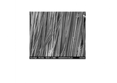
図1は、前記一方向配列不織布の一例の走査型電子顕微鏡による拡大写真(倍率:1000倍)である。図1に示される一方向配列不織布では、複数の長繊維フィラメントのそれぞれが概ね上下方向に沿って配列されている。 FIG. 1 is a magnified photograph (magnification: 1000 times) of an example of the unidirectionally arranged nonwoven fabric by a scanning electron microscope. In the unidirectionally arranged nonwoven fabric shown in FIG. 1, each of the plurality of long fiber filaments is arranged substantially along the vertical direction.
また、本発明による不織布製吸音材に用いられる長繊維不織布は、延伸され且つ一方向に沿って配列された前記複数の長繊維フィラメント(第1の長繊維フィラメント)に加えて、延伸され且つ前記一方向に直交する方向に沿って配列された複数の第2の長繊維フィラメントをさらに有してもよい。すなわち、本発明による不織布製吸音材に用いられる長繊維不織布は、延伸された複数の長繊維フィラメントが直交する二方向のいずれかに沿って配列された構成の「直交配列不織布」であり得る。前記直交する二方向は、厳密に直交している必要はなく、概ね直交していればよい。このような直交配列不織布は、例えば、二つの前記一方向配列不織布を互いの長繊維フィラメントが直交するように積層し且つ融着することによって作製される。なお、前記直交配列不織布においては、前記一方向に沿って配列された前記複数の第1の長繊維フィラメントの繊維径分布の最頻値が1〜4μmにあればよく、前記一方向に直交する方向に配列された前記複数の第2長繊維フィラメントの繊維径分布の最頻値は、必ずしも1〜4μmにある必要はない。例えば、前記直交配列不織布においては、前記一方向に沿って配列された前記複数の第1の長繊維フィラメントの繊維径分布の最頻値が1〜4μmにある一方、前記一方向に直交する方向に沿って配列された前記複数の第2の長繊維フィラメントの繊維径分布の最頻値が4〜11μmにあってもよい。 Further, the long-fiber nonwoven fabric used in the nonwoven fabric-made sound absorbing material according to the present invention is stretched and stretched in addition to the plurality of long-fiber filaments (first long-fiber filaments) stretched and arranged along one direction. It may further have a plurality of second long fiber filaments arranged along a direction orthogonal to one direction. That is, the long-fiber nonwoven fabric used in the nonwoven fabric-made sound absorbing material according to the present invention can be a "orthogonally-arranged nonwoven fabric" in which a plurality of stretched long-fiber filaments are arranged along one of two orthogonal directions. The two orthogonal directions do not have to be strictly orthogonal, but may be substantially orthogonal. Such an orthogonally arranged nonwoven fabric is produced, for example, by laminating and fusing the two above-mentioned unidirectionally arranged nonwoven fabrics so that the long fiber filaments are orthogonal to each other. In the orthogonally arranged nonwoven fabric, the mode of the fiber diameter distribution of the plurality of first long fiber filaments arranged along the one direction may be 1 to 4 μm, and the fibers are orthogonal to the one direction. The mode of the fiber diameter distribution of the plurality of second long fiber filaments arranged in the direction does not necessarily have to be 1 to 4 μm. For example, in the orthogonally arranged nonwoven fabric, the mode of the fiber diameter distribution of the plurality of first long fiber filaments arranged along the one direction is 1 to 4 μm, while the direction orthogonal to the one direction. The mode of the fiber diameter distribution of the plurality of second long fiber filaments arranged along the line may be 4 to 11 μm.
本発明による不織布製吸音材は、上述のように、前記長繊維不織布が複数積み重ねられた不織布積層体を含む。前記不織布積層体は、例えば50枚以上、好ましくは100枚以上の前記長繊維不織布が積み重ねられて構成される。なお、前記不織布積層体において、積み重ねられた各不織布の長繊維フィラメントの軸方向は、同じであってもよいし、ランダムであってもよい。 As described above, the nonwoven fabric sound absorbing material according to the present invention includes a nonwoven fabric laminate in which a plurality of the long fiber nonwoven fabrics are stacked. The nonwoven fabric laminate is composed of, for example, 50 or more, preferably 100 or more, of the long fiber nonwoven fabrics stacked. In the nonwoven fabric laminate, the axial directions of the long fiber filaments of the stacked nonwoven fabrics may be the same or random.
前記不織布積層体は、複数の前記長繊維不織布が厚さ方向に積み重ねられて構成されていればよく、複数の前記長繊維不織布が単に積み重ねられた状態(非圧縮状態)のものであってもよいし、複数の前記長繊維不織布が積み重ねられ、かつ、圧縮された状態(圧縮状態)のものであってもよい。また、前記不織布積層体において、複数の前記長繊維不織布は、互いに分離可能な状態であってもよいし、例えば互いの縁部同士が固定(融着や接着などを含む)されることによってその一部又は全部が一体化されていてもよい。したがって、前記不織布積層体は、例えば同一の設置空間(高さ寸法)等に対し、異なる枚数の前記長繊維不織布によって構成され得る。換言すれば、本発明による不織布製吸音材は、所定の設置空間等に設置される際に、前記積層体を構成する前記長繊維不織布の枚数を調整等することが可能である。また、前記直交配列不織布は、前記不織布積層体を構成する前記長繊維不織布とも言えるし、前記不織布積層体とも言えるものである。 The nonwoven fabric laminate may be configured by stacking a plurality of the long-fiber nonwoven fabrics in the thickness direction, and may be a state in which a plurality of the nonwoven fabrics are simply stacked (uncompressed state). Alternatively, the plurality of the long fiber nonwoven fabrics may be stacked and compressed (compressed state). Further, in the nonwoven fabric laminate, the plurality of nonwoven fabrics of long fibers may be in a state of being separable from each other, and for example, the edges thereof are fixed to each other (including fusion and adhesion). Part or all may be integrated. Therefore, the nonwoven fabric laminate may be composed of different numbers of the long fiber nonwoven fabrics for, for example, the same installation space (height dimension). In other words, the nonwoven fabric sound absorbing material according to the present invention can adjust the number of the long fiber nonwoven fabrics constituting the laminate when installed in a predetermined installation space or the like. Further, the orthogonally arranged nonwoven fabric can be said to be the long fiber nonwoven fabric constituting the nonwoven fabric laminate, or can be said to be the nonwoven fabric laminate.
本発明による不織布製吸音材は、前記不織布積層体のみで形成されてもよいし、前記積層体とこれを収容又は保持する部材とで形成されてもよい。前記不織布積層体を収容又は保持する部材としては、例えば前記不織布積層体を包装する包装体が該当する。前記包装体は、前記不織布積層体の吸音性能を損なわない材質で形成されていればよく、例えば前記不織布積層体を構成する前記長繊維不織布又はそれよりも通気度や空隙率の高い不織布など形成され得る。また、本発明による不織布製吸音材は、多孔質型吸音材などの他の吸音材と組み合わせて使用され得るものである。例えば、本発明による不織布製吸音材は、他の吸音材に重ねられたり(前記他の吸音材の表面に配置されたり)、二つの他の吸音材の間に配置されたりし得る。 The nonwoven fabric sound absorbing material according to the present invention may be formed only of the nonwoven fabric laminate, or may be formed of the laminate and a member that accommodates or holds the laminate. As the member for accommodating or holding the nonwoven fabric laminate, for example, a package for packaging the nonwoven fabric laminate is applicable. The package may be made of a material that does not impair the sound absorbing performance of the nonwoven fabric laminate. For example, the long fiber nonwoven fabric constituting the nonwoven fabric laminate or a nonwoven fabric having a higher air permeability and void ratio than that is formed. Can be done. Further, the non-woven fabric sound absorbing material according to the present invention can be used in combination with other sound absorbing materials such as a porous type sound absorbing material. For example, the non-woven sound absorbing material according to the present invention may be superposed on another sound absorbing material (arranged on the surface of the other sound absorbing material) or may be arranged between two other sound absorbing materials.
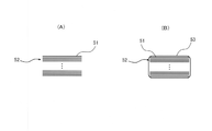
図2(A)は、本発明による不織布製吸音材の第1実施形態を示す概略断面図であり、図2(B)は、本発明による不織布製吸音材の第2実施形態を示す概略断面図である。図2(A)に示されるように、第1実施形態に係る不織布製吸音材は、延伸された複数の長繊維フィラメントが一方向に沿って配列された構成の長繊維不織布51が複数積み重ねられた不織布積層体52からなる。第1実施形態に係る不織布製吸音材は、例えば所定の設置空間に非圧縮状態又は圧縮状態で設置され得る。また、図2(B)に示されるように、第2実施形態に係る不織布製吸音材は、延伸された複数の長繊維フィラメントが一方向に沿って配列された構成の長繊維不織布51が複数積み重ねられた不織布積層体52と、不織布積層体52を包装する包装体53とを含む。第2実施形態に係る不織布製吸音材は、例えば所定の設置空間に非圧縮状態又は圧縮状態で並べて設置されたり、重ねて設置されたりし得る。
FIG. 2A is a schematic cross-sectional view showing a first embodiment of the nonwoven fabric sound absorbing material according to the present invention, and FIG. 2B is a schematic cross section showing a second embodiment of the nonwoven fabric sound absorbing material according to the present invention. It is a figure. As shown in FIG. 2A, in the nonwoven fabric sound absorbing material according to the first embodiment, a plurality of
次に、前記不織布積層体を構成する前記長繊維不織布について具体的に説明する。上述のように、前記不織布積層体を構成する前記長繊維不織布は、前記一方向配列不織布又は前記直交配列不織布であり得る。なお、以下の説明において、「縦方向」とは、前記長繊維不織布を作製する際の機械方向(MD方向)、すなわち、送り方向(前記長繊維不織布の長さ方向に相当する)をいい、「横方向」とは、前記縦方向に垂直な方向(TD方向)、すなわち、前記送り方向に直交する方向(前記長繊維不織布の幅方向に相当する)をいう。また、以下では、長繊維フィラメントを単にフィラメントという場合がある。 Next, the long-fiber nonwoven fabric constituting the nonwoven fabric laminate will be specifically described. As described above, the long-fiber nonwoven fabric constituting the nonwoven fabric laminate may be the unidirectionally arranged nonwoven fabric or the orthogonally arranged nonwoven fabric. In the following description, the "longitudinal direction" refers to the mechanical direction (MD direction) when the long fiber non-woven fabric is produced, that is, the feeding direction (corresponding to the length direction of the long fiber non-woven fabric). The "horizontal direction" means a direction perpendicular to the vertical direction (TD direction), that is, a direction orthogonal to the feed direction (corresponding to the width direction of the long fiber non-woven fabric). Further, in the following, the long fiber filament may be simply referred to as a filament.
[一方向配列不織布]
1.縦配列長繊維不織布
前記一方向配列不織布の一例である縦配列長繊維不織布は、熱可塑性樹脂からなる複数の長繊維フィラメントを縦方向に沿って配列し、すなわち、各長繊維フィラメントの長さ方向(軸方向)が縦方向に概ね一致するように配列し、配列された複数の長繊維フィラメントを縦方向(軸方向)に延伸することによって得られる。このような縦配列長繊維不織布においては、各長繊維フィラメントの構成分子が前記縦方向に配向されている。ここで、前記複数の長繊維フィラメントの前記縦方向への延伸の倍率は3〜6倍である。また、前記縦配列長繊維不織布を構成する前記複数の長繊維フィラメント(すなわち、延伸された複数の長繊維フィラメント)の繊維径分布の最頻値は1〜4μmにあり、好ましくは2〜3μmにある。さらに言えば、前記縦配列長繊維不織布を構成する前記複数の長繊維フィラメントの平均繊維径は1〜4μm、好ましくは2〜3μmであり、前記縦配列長繊維不織布を構成する前記複数の長繊維フィラメントの繊維径分布の変動係数は0.1〜0.3、好ましくは0.15〜0.25である。なお、前記変動係数は、前記縦配列長繊維不織布を構成する前記複数の長繊維フィラメントの繊維径の標準偏差を平均(平均繊維径)で除算した値である。
[One-way array non-woven fabric]
1. 1. Vertically arranged long fiber non-woven fabric The vertically arranged long fiber nonwoven fabric, which is an example of the one-way arranged non-woven fabric, has a plurality of long fiber filaments made of a thermoplastic resin arranged along the vertical direction, that is, in the length direction of each long fiber filament. It is obtained by arranging so that (axial direction) substantially coincides with each other in the vertical direction, and stretching a plurality of arranged long fiber filaments in the longitudinal direction (axial direction). In such a vertically arranged long fiber nonwoven fabric, the constituent molecules of each long fiber filament are oriented in the vertical direction. Here, the magnification of the stretching of the plurality of long fiber filaments in the longitudinal direction is 3 to 6 times. Further, the mode of the fiber diameter distribution of the plurality of long fiber filaments (that is, the plurality of stretched long fiber filaments) constituting the vertically arranged long fiber nonwoven fabric is 1 to 4 μm, preferably 2 to 3 μm. be. Further, the average fiber diameter of the plurality of long fiber filaments constituting the vertically arranged long fiber nonwoven fabric is 1 to 4 μm, preferably 2 to 3 μm, and the plurality of long fibers constituting the vertically arranged long fiber nonwoven fabric. The coefficient of variation of the fiber diameter distribution of the filament is 0.1 to 0.3, preferably 0.15 to 0.25. The coefficient of variation is a value obtained by dividing the standard deviation of the fiber diameters of the plurality of long fiber filaments constituting the vertically arranged long fiber nonwoven fabric by the average (average fiber diameter).
前記長繊維フィラメントは実質的に長繊維であればよく、特に制限されるものではないが、例えば平均長が100mmを超える繊維(フィラメント)であり得る。また、前記長繊維フィラメントの平均繊維径が1〜4μmの範囲内にあればよく、前記縦配列長繊維不織布は、繊維径が1μm未満の長繊維フィラメントや繊維径が4μmを超える長繊維フィラメントを含み得る。なお、長繊維フィラメントの長さ及び繊維径は、例えば、走査型電子顕微鏡よって撮影された前記縦配列長繊維不織布の拡大写真から測定することができ、N個(例えば50個)の測定値から平均繊維径及び標準偏差を求め、前記標準偏差を前記平均繊維径で除算して繊維径分布の変動係数を求めることができる。 The long fiber filament may be a substantially long fiber and is not particularly limited, but may be, for example, a fiber (filament) having an average length of more than 100 mm. Further, the average fiber diameter of the long fiber filaments may be in the range of 1 to 4 μm, and the longitudinally arranged long fiber nonwoven fabric includes long fiber filaments having a fiber diameter of less than 1 μm or long fiber filaments having a fiber diameter of more than 4 μm. Can include. The length and fiber diameter of the long fiber filaments can be measured from, for example, an enlarged photograph of the vertically arranged long fiber non-woven fabric taken by a scanning electron microscope, and from the measured values of N pieces (for example, 50 pieces). The average fiber diameter and standard deviation can be obtained, and the standard deviation can be divided by the average fiber diameter to obtain the coefficient of variation of the fiber diameter distribution.
前記縦配列長繊維不織布の重量目付(以下「目付」という)wは、5〜60g/m2、好ましくは5〜40g/m2、さらに好ましくは10〜30g/m2である。目付は、例えば、300mm×300mmに切り出された不織布シートを複数枚用意し、それぞれの重量を測定してその平均値から算出される。また、前記縦配列長繊維不織布の厚さtは、10〜90μm、好ましくは25〜60μmであり、前記縦配列長繊維不織布の厚さtを目付wで除算した値である比容積t/w(cm3/g)は、2.0〜3.5である。前記比容積t/wが2.0〜3.5の範囲であることは、前記縦配列長繊維不織布の厚さが目付に対して薄いことを意味する。さらに、前記縦配列長繊維不織布の通気度は、5〜250cm3/cm2/s、好ましくは10〜70cm3/cm2/sである。 The weight basis weight (hereinafter referred to as “betsuke”) w of the vertically arranged long fiber nonwoven fabric is 5 to 60 g / m 2 , preferably 5 to 40 g / m 2 , and more preferably 10 to 30 g / m 2 . The basis weight is calculated from, for example, preparing a plurality of non-woven fabric sheets cut into 300 mm × 300 mm, measuring the weight of each, and averaging the weights thereof. The thickness t of the vertically arranged long fiber nonwoven fabric is 10 to 90 μm, preferably 25 to 60 μm, and the specific volume t / w is a value obtained by dividing the thickness t of the vertically arranged long fiber nonwoven fabric by the grain w. (Cm 3 / g) is 2.0 to 3.5. The fact that the specific volume t / w is in the range of 2.0 to 3.5 means that the thickness of the vertically arranged long fiber non-woven fabric is thin with respect to the basis weight. Further, the air permeability of the vertically arranged long fiber nonwoven fabric is 5 to 250 cm 3 / cm 2 / s, preferably 10 to 70 cm 3 / cm 2 / s.
また、前記縦配列長繊維不織布を作製する際のフィラメントの折り畳み幅は、300mm以上であることが好ましい。フィラメントが長繊維として機能するには、折り畳み幅もある程度大きい必要があるからである。なお、フィラメントの折り畳み幅とは、後述するように、紡糸されたフィラメントが縦方向に振動されてコンベア上で折り返して配置される場合における折り返し点間の略直線の部分の平均長さであり、延伸されて前記縦配列長繊維不織布となった状態において目視で観察され得る長さをいうものとする。このような折り畳み幅は、後述の製造方法(製造装置)において、例えば、高速気流の流速及び/又は気流振動機構の回転速度に依存して変化させることができる。 Further, the folding width of the filament when producing the vertically arranged long fiber nonwoven fabric is preferably 300 mm or more. This is because the folding width must be large to some extent in order for the filament to function as a long fiber. The folding width of the filament is, as will be described later, the average length of a substantially straight line portion between the folding points when the spun filament is vibrated in the vertical direction and folded back on the conveyor. It refers to the length that can be visually observed in the state of being stretched into the vertically arranged long fiber non-woven fabric. Such a folding width can be changed depending on, for example, the flow velocity of the high-speed airflow and / or the rotation speed of the airflow vibration mechanism in the manufacturing method (manufacturing apparatus) described later.
前記長繊維フィラメントは、熱可塑性樹脂を溶融紡糸して得られる。前記熱可塑性樹脂は、溶融紡糸可能な樹脂であればよく、特に制限されるものではないが、主にポリエステル、特に固有粘度IVが0.43〜0.63、好ましくは0.48〜0.58であるポリエチレンテレフタレートが用いられる。あるいは、前記熱可塑性樹脂としてポリプロピレンが用いられてもよい。これらはメルトブロー法などでの紡糸性が良好なためである。なお、前記熱可塑性樹脂は、酸化防止剤、耐候剤、着色剤などの添加剤を0.01〜2重量%程度含んでもよい。また、前記熱可塑性樹脂として、難燃性樹脂、例えばリン系の難燃成分を共重合させることによって難燃化した難燃性ポリエステルが用いられてもよい。 The long fiber filament is obtained by melt-spinning a thermoplastic resin. The thermoplastic resin may be any resin that can be melt-spun, and is not particularly limited, but mainly polyester, particularly having an intrinsic viscosity IV of 0.43 to 0.63, preferably 0.48 to 0. Polyethylene terephthalate which is 58 is used. Alternatively, polypropylene may be used as the thermoplastic resin. These are due to the good spinnability in the melt blow method and the like. The thermoplastic resin may contain about 0.01 to 2% by weight of additives such as antioxidants, weathering agents, and colorants. Further, as the thermoplastic resin, a flame-retardant resin, for example, a flame-retardant polyester made flame-retardant by copolymerizing a phosphorus-based flame-retardant component may be used.
次に、前記縦配列長繊維不織布の製造方法の一例を説明する。前記縦配列長繊維不織布の製造方法は、複数の長繊維フィラメントが縦方向に沿って配列された構成の不織布ウェブを作製する工程と、作製された不織布ウェブ(すなわち、縦方向に沿って配列された複数の長繊維フィラメント)を縦方向に一軸延伸することによって縦配列長繊維不織布を得る工程とを含む。 Next, an example of the method for manufacturing the vertically arranged long fiber nonwoven fabric will be described. The method for producing a longitudinally-arranged long-fiber nonwoven fabric includes a step of producing a nonwoven fabric web having a structure in which a plurality of long-fiber filaments are arranged along the vertical direction, and the produced nonwoven fabric web (that is, arranged along the longitudinal direction). This includes a step of obtaining a longitudinally arranged long fiber nonwoven fabric by uniaxially stretching the plurality of long fiber filaments) in the vertical direction.
詳細には、前記不織布ウェブを作製する工程は、複数(多数)本のフィラメントを押し出すノズル群、前記ノズル群から押し出されたフィラメントを捕集して搬送するコンベアベルト及び前記フィラメントに吹き付けられる高速気流を振動させる気流振動手段を準備する工程と、前記ノズル群から複数(多数)のフィラメントを前記コンベアベルトに向けて押し出す工程と、前記ノズル群から押し出された各フィラメントを高速気流に随伴させて細径化する工程と、前記気流振動手段によって前記高速気流の向きを前記コンベアベルトの走行方向(すなわち、縦方向)に周期的に変動させる工程と、を含み、複数のフィラメントが前記コンベアベルトの走行方向(縦方向)に沿って配列された不織布ウェブを作製する。また、前記縦配列長繊維不織布を得る工程は、前記不織布ウェブを作製する工程で作製された不織布ウェブを縦方向に一軸延伸し、これによって、前記縦配列長繊維不織布を得る。なお、前記延伸の倍率は、3〜6倍である。 Specifically, in the step of producing the nonwoven fabric web, a nozzle group that extrudes a plurality of (many) filaments, a conveyor belt that collects and conveys the filament extruded from the nozzle group, and a high-speed airflow blown onto the filament. A step of preparing a flow vibration means for vibrating the A plurality of filaments travel on the conveyor belt, including a step of increasing the diameter and a step of periodically changing the direction of the high-speed airflow in the traveling direction (that is, the vertical direction) of the conveyor belt by the airflow vibration means. Produce a non-woven web arranged along the direction (longitudinal). Further, in the step of obtaining the longitudinally arranged long fiber non-woven fabric, the nonwoven fabric web produced in the step of producing the nonwoven fabric web is uniaxially stretched in the vertical direction, whereby the longitudinally arranged long fiber non-woven fabric is obtained. The magnification of the stretching is 3 to 6 times.
ここで、前記ノズル群に関し、ノズル数、ノズル孔数、ノズル孔間ピッチP、ノズル孔直径D及びノズル孔長さLは、任意に設定され得るが、ノズル孔直径Dが0.1〜0.2mm、L/Dが10〜40であるのが好ましい。 Here, with respect to the nozzle group, the number of nozzles, the number of nozzle holes, the pitch P between nozzle holes, the nozzle hole diameter D and the nozzle hole length L can be arbitrarily set, but the nozzle hole diameter D is 0.1 to 0. It is preferable that the thickness is 2 mm and the L / D is 10 to 40.
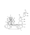
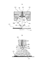
図3は、前記縦配列長繊維不織布の製造装置の一例の概略構成図である。図3に示される製造装置は、メルトブロー法によって前記縦配列長繊維不織布を製造するように構成されており、メルトブローダイス1、コンベアベルト7、気流振動機構9、延伸シリンダ12a、12b及び引取ニップローラ16a、16bなどを含む。
FIG. 3 is a schematic configuration diagram of an example of the above-mentioned vertically arranged long fiber nonwoven fabric manufacturing apparatus. The manufacturing apparatus shown in FIG. 3 is configured to manufacture the longitudinally arranged long fiber nonwoven fabric by the melt blow method, and includes a melt blow die 1, a
まず、装置の前段において、熱可塑性樹脂(ここでは、ポリエステル又はポリプロピレン)を主成分とする熱可塑性樹脂)が押出機(図示省略)に投入され、溶融され、押し出されてメルトブローダイス1に送られる。 First, in the front stage of the apparatus, a thermoplastic resin (here, a thermoplastic resin containing polyester or polypropylene as a main component) is charged into an extruder (not shown), melted, extruded, and sent to the melt blow die 1. ..
メルトブローダイス1は、その先端(下端)に、紙面に対して垂直な方向、すなわち、コンベアベルト7の走行方向に垂直に並べられた多数のノズル3を有する。ギアポンプ(図示省略)などによってメルトブローダイス1に送られた溶融樹脂2が各ノズル3から押し出されることで、多数のフィラメント11が形成(紡糸)される。なお、図3においては、メルトブローダイス1は断面図で示されているため、ノズル3は一つしか示されていない。また、メルトブローダイス1において、各ノズル3の両側にはそれぞれエアー溜め5a,5bが設けられている。前記熱可塑性樹脂の融点以上に加熱された高圧加熱エアーは、これらエアー溜め5a,5bに送入され、その後、エアー溜め5a,5bに連通すると共にメルトブローダイス1の先端に開口するスリット6a,6bから噴出される。これにより、ノズル3の下方には、ノズル3からのフィラメント11の押し出し方向とほぼ平行な高速気流が形成される。この高速気流によって、ノズル3から押し出されたフィラメント11がドラフト可能な溶融状態に維持されると共に、高速気流の摩擦力によりフィラメント11にドラフトが与えられて(すなわち、フィラメント11が引っ張られて)フィラメント11が細径化される。なお、紡糸直後のフィラメント11の直径は、好ましくは10μm以下である。また、ノズル3の下方に形成される高速気流の温度は、フィラメント11の紡糸温度よりも20℃以上、望ましくは40℃以上高く設定される。
The melt blow die 1 has a large number of nozzles 3 arranged at its tip (lower end) in a direction perpendicular to the paper surface, that is, perpendicular to the traveling direction of the
メルトブローダイス1を用いてフィラメント11を形成する方法では、前記高速気流の温度を高くすることにより、ノズル3から押し出された直後のフィラメント11の温度をフィラメント11の融点よりも十分に高くすることができ、これによって、フィラメント11の細径化が可能である。
In the method of forming the
メルトブローダイス1の下方にはコンベアベルト7が配置されている。コンベアベルト7は、図示省略の駆動源により回転されるコンベアローラ13やその他のローラに掛け回されている。コンベアローラ13の回転によってコンベアベルト7を駆動することで、ノズル3から押出されてコンベアベルト7上に捕集されたフィラメント11が図3における矢印方向(右方向)へ搬送される。
A
メルトブローダイス1とコンベアベルト7との間の所定位置、具体的には、ノズル3の両側のスリット6a,6bから噴出された高圧加熱エアーが合流して形成される高速気流の流域(近傍)には、気流振動機構9が設けられている。気流振動機構9は、断面が楕円形の楕円柱部と、楕円柱部の両端のそれぞれから延びる支持軸9aとを有し、コンベアベルト7によるフィラメント11の搬送方向(コンベアベルト7の走行方向)にほぼ直交する方向、すなわち、製造すべき縦配列長繊維不織布の幅方向とほぼ平行に配置されている。そして、気流振動機構9は、支持軸9aが回転されることで前記楕円柱部が矢印A方向に回転するように構成されている。このように前記高速気流の近傍に楕円柱状の気流振動機構9を配置し、これを回転させることによって、後述するようにコアンダ効果を利用して前記高速気流の向きを変えることができる。なお、気流振動機構9の数は一つに限られるものではなく、必要に応じて複数個設けて、フィラメント11の振れ幅をより大きくしてもよい。
In a predetermined position between the melt blow die 1 and the
フィラメント11は、前記高速気流に沿って流れる。前記高速気流は、スリット6a,6bから噴出された高圧加熱エアーが合流して形成され、コンベアベルト7の搬送面とほぼ垂直な方向に流れる。ところで、気体や液体の高速噴流近傍に壁が存在しているとき、噴流が壁面の近くを流れる傾向があることは一般に知られている。これをコアンダ効果という。気流振動機構9は、このコアンダ効果を利用して前記高速気流、すなわち、フィラメント11の流れの向きを変える。
The
気流振動機構9(前記楕円柱部)の幅、すなわち、支持軸9aと平行な方向における気流振動機構9の長さは、メルトブローダイス1によって紡糸されるフィラメント群の幅よりも100mm以上大きいことが望ましい。これよりも気流振動機構9の幅が小さいと、フィラメント群の両端部で前記高速気流の流れ方向を十分に変えられず、フィラメント群の両端部でのフィラメント11の縦方向に沿った配列が不十分になるおそれがあるからである。また、気流振動機構9(前記楕円柱部)の周壁面9bと前記高速気流の気流軸100との距離は、最も小さいときで25mm以下、望ましくは15mm以下である。気流振動機構9と気流軸100との距離がこれ以上大きくなると、前記高速気流が気流振動機構9に引き寄せられる効果が小さくなって、フィラメント11を十分に振らせることができなくなるおそれがあるからである。
The width of the airflow vibration mechanism 9 (the elliptical pillar portion), that is, the length of the
ここで、フィラメント11の振れ幅は、前記高速気流の流速と気流振動機構9の回転速度に依存する。したがって、高速気流の速度は10m/sec以上、好ましくは15m/sec以上となるように設定される。これ以下の速度では、前記高速気流が気流振動機構9の周壁面9bに十分に引き寄せられず、結果的にフィラメント11を十分に振らせることができなくなるおそれがあるである。気流振動機構9の回転速度は、周壁面9bにおける振動数を、フィラメント11の振れ幅を最大とする振動数とすればよい。このような振動数は、紡糸条件によっても異なるため、前記紡糸条件に応じて適宜決定される。
Here, the swing width of the
また、図3に示された製造装置においては、メルトブローダイス1とコンベアベルト7との間に、スプレーノズル8が設けられている。スプレーノズル8は、前記高速気流中に霧状の水等を噴霧するものであり、スプレーノズル8による水等の噴霧によってフィラメント11が冷却されて、急速に凝固する。なお、スプレーノズル8は実際には複数個設置されるが、煩雑さを避けるため、図3では1個のスプレーノズル8のみが示されている。
Further, in the manufacturing apparatus shown in FIG. 3, a
凝固したフィラメント11は、縦方向に振られながらコンベアベルト7上に集積され、縦方向に部分的に折り畳まれて連続的に捕集される。コンベアベルト7上のフィラメント11は、コンベアベルト7によって図3における矢印方向(右方向)に搬送され、延伸温度に加熱された延伸シリンダ12aと押さえローラ14とにニップされて、延伸シリンダ12aに移される。その後、フィラメント11は、延伸シリンダ12bと押えゴムローラ15とにニップされて延伸シリンダ12bに移され、2つの延伸シリンダ12a,12bに密着される。このように、フィラメント11が延伸シリンダ12a,12bに密着しながら送られることによって、フィラメント11は、縦方向に部分的に折り畳まれた状態のまま、隣接するフィラメント同士が融着した不織布ウェブとなる。
The solidified
前記不織布ウェブは、その後に、引取ニップローラ16a,16b(後段の引取ニップローラ16bはゴム製)で引き取られる。引取ニップローラ16a,16bの周速は、延伸シリンダ12a,12bの周速よりも大きく設定されており、これにより、前記不織布ウェブが縦方向に3〜6倍に延伸される。このようにして、縦配列長繊維不織布18が製造される。なお、前記不織布ウェブは、必要に応じて、熱処理や熱エンボス等の部分接着処理などの後処理がさらに行われてもよい。また、延伸倍率は、例えば、延伸前の不織布ウェブに一定の間隔で入れたマークによって次式で定義され得る。
延伸倍率=「延伸後のマーク間の長さ」/「延伸前のマーク間の長さ」
The non-woven fabric web is subsequently taken up by the take-up nip
Stretching ratio = "length between marks after stretching" / "length between marks before stretching"
上述のように、製造された縦配列長繊維不織布18を構成するフィラメントの平均繊維径は1〜4μm(好ましくは2〜3μm)であり、製造された縦配列長繊維不織布18を構成するフィラメントの繊維径分布の変動係数は0.1〜0.3である。また、好ましい態様において、縦配列長繊維不織布18は、繊維の方向、すなわち、長繊維フィラメントの軸方向であり且つ延伸方向である縦方向への伸び率が、1〜20%、好ましくは5〜15%である。すなわち、縦配列長繊維不織布18は、縦方向に伸縮性を有するものであり得る。さらに、縦配列長繊維不織布18の縦方向の引張強度は、20N/50mm以上である。前記伸び率及び前記引張強度は、JIS L1096 8.14.1 A法により測定した値である。
As described above, the average fiber diameter of the filaments constituting the manufactured longitudinally arranged long
2.横配列長繊維不織布
前記一方向配列不織布の他の例である横配列長繊維不織布は、熱可塑性樹脂からなる複数の長繊維フィラメントを横方向に沿って、すなわち、各長繊維フィラメントの長さ方向(軸方向)が概ね前記横方向に一致するように配列し、配列された複数の長繊維フィラメントを横方向(軸方向)に延伸することによって得られる。このような横配列長繊維不織布においては、各長繊維フィラメントの構成分子が前記横方向に配向されている。ここで、前記縦配列長繊維不織布の場合と同様に、前記長繊維フィラメントの延伸倍率は3〜6倍である。また、前記横配列長繊維不織布を構成する前記複数の長繊維フィラメントの繊維径分布の最頻値は1〜4μmにあり、好ましくは2〜3μmにある。さらに言えば、前記横配列長繊維不織布を構成する前記複数の長繊維フィラメントの平均繊維径は1〜4μm、好ましくは2〜3μmであり、前記横配列長繊維不織布を構成する前記複数の長繊維フィラメントの繊維径分布の変動係数は0.1〜0.3、好ましくは0.15〜0.25である。
2. 2. Horizontally Arranged Long Fiber Nonwoven Fabric Another example of the unidirectionally arranged long fiber nonwoven fabric is a horizontally arranged long fiber nonwoven fabric in which a plurality of long fiber filaments made of a thermoplastic resin are formed along the transverse direction, that is, in the length direction of each long fiber filament. It is obtained by arranging so that (axial direction) substantially coincides with the lateral direction and stretching a plurality of arranged long fiber filaments in the lateral direction (axial direction). In such a transversely arranged long fiber nonwoven fabric, the constituent molecules of each long fiber filament are oriented in the lateral direction. Here, as in the case of the vertically arranged long fiber non-woven fabric, the draw ratio of the long fiber filament is 3 to 6 times. The mode of the fiber diameter distribution of the plurality of long fiber filaments constituting the horizontally arranged long fiber nonwoven fabric is 1 to 4 μm, preferably 2 to 3 μm. Furthermore, the average fiber diameter of the plurality of long fiber filaments constituting the transversely arranged long fiber nonwoven fabric is 1 to 4 μm, preferably 2 to 3 μm, and the plurality of elongated fibers constituting the transversely arranged long fiber nonwoven fabric. The coefficient of variation of the fiber diameter distribution of the filament is 0.1 to 0.3, preferably 0.15 to 0.25.
また、前記横配列長繊維不織布の目付wは、5〜60g/m2、好ましくは5〜40g/m2、さらに好ましくは10〜30g/m2であり、前記横配列長繊維不織布の厚さtは、10〜90μm、好ましくは20〜70μmであり、前記横配列長繊維不織布の厚さtを目付wで除算した値である比容積t/w(cm3/g)は、2.0〜3.5である。さらに、前記横配列長繊維不織布の通気度は、5〜250cm3/cm2/sであり、好ましくは10〜70cm3/cm2/sである。 The texture w of the horizontally arranged long fiber nonwoven fabric is 5 to 60 g / m 2 , preferably 5 to 40 g / m 2 , more preferably 10 to 30 g / m 2 , and the thickness of the horizontally arranged long fiber nonwoven fabric. t is 10 to 90 μm, preferably 20 to 70 μm, and the specific volume t / w (cm 3 / g), which is the value obtained by dividing the thickness t of the transversely arranged long fiber nonwoven fabric by the grain w, is 2.0. ~ 3.5. Further, the air permeability of the horizontally arranged long fiber nonwoven fabric is 5 to 250 cm 3 / cm 2 / s, preferably 10 to 70 cm 3 / cm 2 / s.
なお、以下では、前記縦配列長繊維不織布の場合と同様でよいものについての説明は適宜省略する。 In the following, the description of what may be the same as in the case of the vertically arranged long fiber nonwoven fabric will be omitted as appropriate.
次に、前記横配列長繊維不織布の製造方法の一例を説明する。前記横配列長繊維不織布の製造方法は、複数の長繊維フィラメントが横方向に沿って配列された不織布ウェブを作製する工程と、作製された不織布ウェブ(すなわち、横方向に沿って配列されや複数の長繊維フィラメント)を横方向に一軸延伸することによって横配列長繊維不織布を得る工程とを含む。 Next, an example of the method for manufacturing the horizontally arranged long fiber nonwoven fabric will be described. The method for producing a transversely-arranged long-fiber nonwoven fabric includes a step of producing a nonwoven fabric web in which a plurality of long-fiber filaments are arranged along the transverse direction, and a plurality of the prepared nonwoven fabric webs (that is, the nonwoven fabric webs arranged along the transverse direction). This includes a step of obtaining a transversely arranged long fiber nonwoven fabric by uniaxially stretching the long fiber filament).
詳細には、前記不織布ウェブを作製する工程は、複数(多数)本のフィラメントを押し出すノズル群、前記ノズル群から押し出されたフィラメントを捕集して搬送するコンベアベルト及び前記フィラメントに吹き付けられる高速気流を振動させる気流振動手段を準備する工程と、前記ノズル群から複数(多数)本のフィラメントを前記コンベアベルトに向けて押し出す工程と、前記ノズル群から押し出された各フィラメントを高速気流に随伴させて細径化する工程と、前記気流振動手段によって前記高速気流の向きを前記コンベアベルトの走行方向に垂直な方向(すなわち、横方向)に周期的に変動させる工程と、を含み、複数のフィラメントが前記コンベアの進行方向に垂直な方向(横方向)に配列された不織布ウェブを作製する。また、前記横配列長繊維不織布を得る工程は、前記不織布ウェブを作製する工程で作成された不織布ウェブを横方向に一軸延伸し、これによって、前記横配列長繊維不織布を得る。なお、前記延伸の倍率は、3〜6倍である。 Specifically, in the step of producing the nonwoven fabric web, a nozzle group that extrudes a plurality of (many) filaments, a conveyor belt that collects and conveys the filament extruded from the nozzle group, and a high-speed airflow blown onto the filament. A step of preparing a flow vibration means for vibrating the A plurality of filaments include a step of reducing the diameter and a step of periodically changing the direction of the high-speed airflow in a direction perpendicular to the traveling direction of the conveyor belt (that is, a lateral direction) by the airflow vibration means. A non-woven fabric web arranged in a direction perpendicular to the traveling direction (horizontal direction) of the conveyor is produced. Further, in the step of obtaining the transversely arranged long fiber non-woven fabric, the nonwoven fabric web created in the step of producing the nonwoven fabric web is uniaxially stretched in the lateral direction, whereby the above-mentioned transversely arranged long fiber nonwoven fabric is obtained. The magnification of the stretching is 3 to 6 times.
図4は、前記横配列長繊維不織布の製造装置の一例(以下「第1製造装置」という)の概略構成図である。前記横配列長繊維不織布の第1製造装置は、メルトブロー法によって前記横配列長繊維不織布を製造するように構成されており、図4に示されるように、メルトブローダイス101、コンベアベルト107、気流振動機構109及び図示省略の延伸装置などを含む。なお、図4において、メルトブローダイス101は内部構造が分かるように断面で示されている。
FIG. 4 is a schematic configuration diagram of an example of the manufacturing apparatus for the horizontally arranged long fiber nonwoven fabric (hereinafter referred to as “first manufacturing apparatus”). The first manufacturing apparatus for the horizontally arranged long fiber nonwoven fabric is configured to manufacture the horizontally arranged long fiber nonwoven fabric by the melt blow method, and as shown in FIG. 4, the melt blow die 101, the
まず、装置の前段において、熱可塑性樹脂(ここでは、ポリエステル又はポリプロピレン)を主成分とする熱可塑性樹脂)が押出機(図示省略)に投入され、溶融され、押し出されてメルトブローダイス101に送られる。 First, in the front stage of the apparatus, a thermoplastic resin (here, a thermoplastic resin containing polyester or polypropylene as a main component) is charged into an extruder (not shown), melted, extruded, and sent to a melt blow die 101. ..
メルトブローダイス101は、その先端(下端)に、紙面に対して垂直な方向に、すなわち、コンベアベルト107の進行方向に沿って並べられた多数のノズル103を有する。ギアポンプ(図示省略)などによってメルトブローダイス101に送られた溶融樹脂が各ノズル103から押し出されることで、多数のフィラメント111が形成(紡糸)される。また、各ノズル103の両側にはそれぞれエアー溜め105a,105bが設けられている。前記熱可塑性樹脂の融点以上に加熱された高圧加熱エアーは、これらエアー溜め105a,105bに送入され、その後、エアー溜め105a,105bに連通すると共にメルトブローダイス101の先端に開口するスリット106a,106bから噴出される。これにより、ノズル103からのフィラメント111の押し出し方向とほぼ平行な高速気流がノズル103の下方に形成され、この高速気流によって、ノズル103から押し出されたフィラメント111がドラフト可能な溶融状態に維持されると共に、前記高速気流の摩擦力によりフィラメント111にドラフトが与えられてフィラメント111が細径化される。前記高速気流の温度は、フィラメント111の紡糸温度よりも20℃以上、望ましくは40℃以上高く設定される。
The melt blow die 101 has a large number of
前記縦配列長繊維不織布の場合と同様に、前記高速気流の温度を高くすることにより、ノズル103から押し出された直後のフィラメント111の温度をフィラメント111の融点よりも十分に高くすることができ、これによって、フィラメント111の細径化が可能である。
As in the case of the vertically arranged long fiber nonwoven fabric, by raising the temperature of the high-speed airflow, the temperature of the
メルトブローダイス101の下方にはコンベアベルト107が配置されている。コンベアベルト107は、図示省略の駆動源により回転されるコンベアローラやその他のローラ(いずれも図示省略)に掛け回されている。前記コンベアローラの回転によってコンベアベルト107を駆動することで、ノズル103から押し出されたフィラメント111、さらに言えば、フィラメント111がコンベアベルト107上に集積してなる不織布ウェブ120が、図4における紙面の奥から手前に向かって又は手前から奥へ向かって搬送される。
A
メルトブローダイス101とコンベアベルト107との間の所定位置、具体的には、スリット106a,106bから噴出された高圧加熱エアーが合流して形成される高速気流の流域(近傍)には、楕円柱状の気流振動機構109が設けられている。気流振動機構109は、断面が楕円形の楕円柱部と、楕円柱部の両端のそれぞれから延びる支持軸109aとを有し、コンベアベルト107によるフィラメント111(ウェブ120)の搬送方向と平行に配置されている。そして、気流振動機構109は、支持軸109aが回転されることで前記楕円柱部が矢印A方向に回転するように構成されている。
A predetermined position between the melt blow die 101 and the
気流振動機構109は、図3の気流振動機構9と同様、コアンダ効果を利用して前記高速気流(フィラメント111の流れ)の向きを変えることができる。すなわち、気流振動機構109を回転させることにより、フィラメント111を周期的に振動させることができる。気流振動機構109の支持軸109aはコンベアベルト107によるフィラメント111(ウェブ120)の搬送方向と平行に配置されているので、フィラメント111は、コンベアベルト107による搬送方向に垂直な方向、すなわち、製造すべき横配列長繊維不織布の幅方向に振動する。これにより、フィラメント111が幅方向に沿って配列された幅Sの不織布ウェブ120がコンベアベルト107上に作製される。
Similar to the
気流振動機構109の周壁面109bが前記高速気流の気流軸100に最も近づいた状態での気流軸100と周壁面109bとの距離をL1とする。また、ノズル103先端と略同一平面を構成するメルトブローダイス101の下端面と、気流振動機構109の支持軸109a中心との距離をL2とする。基本的には、これらL1及びL2が小さいほど、コンベアベルト107上に作製される不織布ウェブ120の幅Sは大きくなる。しかし、L1が小さすぎると、フィラメント111が気流振動機構109に巻き付く等のトラブルが発生するおそれがあり、また、L2についても、気流振動機構109の断面の大きさ等により自ずと制限される。一方、L1及びL2が大きすぎると、気流振動機構109の周壁面109bによるフィラメント111の振動の効果が小さくなる。以上のことを考慮して、L1は、30mm以下であることが好ましく、さらに好ましくは15mm以下であり、最も好ましいのは10mm以下である。また、L2は、80mm以下であることが好ましく、さらに好ましくは55mm以下であり、最も好ましいのは52mm以下である。ただし、気流振動機構109は、フィラメント111に衝突しない位置に配置する必要がある。
Let L1 be the distance between the
また、フィラメント111の振れ幅(不織布ウェブ120の幅S)は、前記高速気流の流速及び気流振動機構109の回転速度にも依存する。気流振動機構109の回転による気流軸100と周壁面109bとの距離の変動を周壁面109bの振動とすると、フィラメント111の振れ幅を最大とするような、周壁面109bの振動数が存在する。この振動数以外では、周壁面109bの振動数と前記高速気流の持つ固有の振動数とが異なるため、フィラメント111の振れ幅も小さくなる。この振動数は、紡糸条件によって異なるが、一般的な紡糸手段により紡糸されたフィラメント111を振動させる場合には、5Hz以上30Hz以下の範囲が好ましく、より好ましくは10Hz以上20Hz以下、最も好ましくは12Hz以上18Hz以下の範囲である。また、前記高速気流の速度は、10m/sec以上、好ましくは15m/sec以上である。これ以下の速度では、フィラメント111を十分に振らせることができなくなるおそれがあるからである。
Further, the swing width of the filament 111 (width S of the nonwoven fabric web 120) also depends on the flow velocity of the high-speed airflow and the rotation speed of the
なお、気流振動機構109の長さは、メルトブローダイス101によって紡糸されるフィラメント群の幅よりも100mm以上大きいことが望ましい。これよりも気流振動機構109の長さが短いと、フィラメント群の両端部で前記高速気流の流れ方向を十分に変えられず、フィラメント群の両端部でのフィラメント111の横方向に沿った配列が不十分になるおそれがあるからである。
It is desirable that the length of the
コンベアベルト107上の不織布ウェブ120は、コンベアベルト107により紙面手前又は紙面奥に向かって搬送され、その後、図示省略の延伸装置によって横方向に3〜6倍に延伸される。このようにして、横配列長繊維不織布が製造される。前記延伸装置としては、プーリ式延伸装置やテンター延伸装置などが挙げられるが、これらには限定されない。なお、不織布ウェブ120は、必要に応じて、熱処理や熱エンボス等の部分接着処理等の後処理がさらに行われてもよい。なお、縦配列長繊維不織布の製造装置(図3)と同様に、横配列長繊維不織布の第1製造装置(図4)が、フィラメントを急冷するために霧状の水等を噴霧するためのスプレーノズル等を備えてもよい。
The
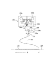
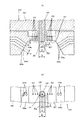
図5は、前記横配列長繊維不織布の製造装置の他の例(以下「第2製造装置」という)の要部構成を示す図である。図5(A)は、前記横配列長繊維不織布の第2製造装置の正面図であり、図5(B)は、前記横配列長繊維不織布の第2製造装置の側面図である。図5(A)、(B)に示されるように、前記横配列長繊維不織布の第2製造装置は、紡糸ヘッド210、コンベアベルト219及び図示省略の延伸装置などを含む。なお、図5(A)、(B)において、紡糸ヘッド210は、内部構造が分かるように断面図で示されている。また、本製造装置において、コンベアベルト219は、紡糸ヘッド210に下方に配置され、図5(A)における矢印方向(左方向)に走行するように構成されている。
FIG. 5 is a diagram showing a main configuration of another example of the horizontal arrangement long fiber nonwoven fabric manufacturing apparatus (hereinafter referred to as “second manufacturing apparatus”). FIG. 5A is a front view of the second manufacturing apparatus for the horizontally arranged long fiber nonwoven fabric, and FIG. 5B is a side view of the second manufacturing apparatus for the horizontally arranged long fiber nonwoven fabric. As shown in FIGS. 5A and 5B, the second manufacturing apparatus for the transversely arranged long fiber nonwoven fabric includes a spinning
図6は、紡糸ヘッド210を示している。図6(A)は、紡糸ヘッド210の断面図であり、図6(B)は、紡糸ヘッド210を下側から見た図である。
FIG. 6 shows the spinning
紡糸ヘッド210は、エアー噴出部206と、エアー噴出部206の内部に配置された円筒状の紡糸ノズル部205とを含む。紡糸ノズル部205の内部には、重力方向に延びると共に紡糸ノズル部205の下端面に開口する紡糸ノズル201が形成されている。紡糸ノズル201のノズル孔径Nzは、任意に設定され得るが、例えば0.1〜0.7mmである。紡糸ヘッド210は、紡糸ノズル201がコンベアベルト219の幅方向のほぼ中央に位置するように、コンベアベルト219に上方に配置される。紡糸ノズル201には、ギアポンプ(図示省略)などによってその上側から溶融樹脂が供給され、供給された溶融樹脂が紡糸ノズル201を通って紡糸ノズル201の下側の開口端から下方へ押し出されることによってフィラメント211が形成(紡糸)される。
The spinning
エアー噴出部206の下面には、二つの斜面208a,208bを有する凹部が形成されている。前記凹部の底面は、重力方向に対して垂直な水平面207を構成しており、一方の斜面208aは、コンベアベルト219の走行方向における水平面207の一端側に配置され、他方の斜面208bは、コンベアベルト219の走行方向における水平面207の他側に配置されている。2つの斜面208a,208bは、水平面207に直交すると共に紡糸ノズル201の中心線を通る平面に関して対称に配置されており、下方に向かって互いの距離が徐々に大きくなるようにそれぞれ傾斜して形成されている。
A recess having two
紡糸ノズル部205の下端面は、エアー噴出部206の水平面207の中央部において水平面207から突出するように配設されている。紡糸ノズル部205の下端面の水平面207から突出量Hは、任意に設定され得るが、例えば0.01〜1mmである。また、紡糸ノズル部205の外周面とエアー噴出部206との間には、高温の一次エアーを噴出する円環状の一次エアースリット202が形成されている。なお、紡糸ノズル部205の外径、すなわち、一次エアースリット202の内径dは、任意に設定され得るが、例えば2.5〜6mmである。なお、図示は省略するが、主に一次エアースリット202から噴出させる一次エアーの速度及び温度を均一化するため、紡糸ヘッド210の内部には、少なくとも一部の隙間が0.1〜0.5mmであるスリット状流路が形成されており、このスリット状流路を介して高温の一次エアーが一次エアースリット202に供給される。
The lower end surface of the spinning
一次エアースリット202には、その上部から高温の一次エアーが供給され、供給された一次エアーが一次エアースリット202内を通って一次エアースリット202の水平面207側の開口端から下方に向かって高速で噴出される。このように一次エアースリット202から一次エアーが高速で噴出されることで、紡糸ノズル部205の下端面の下方で減圧部分が生じ、この減圧によって紡糸ノズル201から押し出されたフィラメント211が振動する。
High-temperature primary air is supplied to the primary air slit 202 from above, and the supplied primary air passes through the primary air slit 202 at high speed downward from the opening end of the primary air slit 202 on the
さらに、エアー噴出部206には、高温の二次エアーを噴出する二次エアー噴出口204a,204bが形成されている。二次エアーは、一次エアースリット202から噴出された一次エアーによって振動するフィラメント211を広げて一方向に配列させるために噴出される。二次エアー噴出口204aは、斜面208aに開口形成されており、エアー噴出部206の内部に向かって斜面208aに対して垂直に延びている。同様に、二次エアー噴出口204bは、斜面208bに開口形成されており、エアー噴出部206の内部に向かって斜面208bに対して垂直に延びている。二次エアー噴出口204a,204bは、水平面207に直交すると共に紡糸ノズル201の中心線を通る平面に関して対称に配置されている。なお、二次エアー噴出口204a,204bの直径rは、任意に設定され得るが、1.5〜5mmであるのが好ましい。また、本実施形態では、二次エアー噴出口204a,204bがそれぞれ二つずつ形成されているが、これに限られるものではなく、二次エアー噴出口204a,204bの数は任意に設定され得る。
Further, the
二次エアー噴出口204a,204bのそれぞれからは、水平な方向よりも僅かに下向きに二次エアーが噴出される。そして、二次エアー噴出口204aから噴出された二次エアーと、二次エアー噴出口204bから噴出された二次エアーとは、紡糸ノズル201の下方で衝突してコンベアベルト219の幅方向に広がる。これにより、振動しながら落下するフィラメント211がコンベアベルト219の幅方向に広がる。
Secondary air is ejected from each of the
また、紡糸ノズル部205を挟んでその両側には、紡糸ノズル201と平行に延びると共に水平面207に開口する複数の小孔203が形成されている。複数の小孔203は、紡糸ノズル201の中心線と直交する一直線上に一列に並んでおり、紡糸ノズル部205の二次エアー噴出口204a側と204b側とのそれぞれに同数(ここでは3つ)形成されている。複数の小孔203は、水平面207の開口端から高温のエアーを下方に向けて噴出するように構成されており、これにより、フィラメント211の紡糸が安定する。なお、小孔203の径qは、任意に設定され得るが、概ね1mm程度であるのが好ましい。また、各小孔203から噴出させる高温のエアーは、一次エアースリット202から噴出させるための一次エアーの発生源から導かれてもよいし、二次エアー噴出口204a,204bから噴出させるための二次エアーの発生源から導かれてもよい。あるいは、一次エアー及び二次エアーとは別の高温のエアーが各小孔203に供給されてもよい。
Further, on both sides of the spinning
さらに、紡糸ヘッド210とコンベアベルト219との間には、一対の冷却ノズル220が設けられている。本実施形態において、一方の冷却ノズル220は、紡糸ノズル201から紡出されたフィラメント211のコンベアベルト219の走行方向の上流側に配置され、他方の冷却ノズル220は、紡糸ノズル201から紡出されたフィラメント211のコンベアベルト219の走行方向の下流側の配置されている。各冷却ノズル220は、コンベアベルト219に到達する前のフィラメント211に霧状の水等を噴霧し、これにより、フィラメント211が冷却されて凝固する。なお、冷却ノズル220の数や配置は任意に設定され得る。
Further, a pair of cooling
凝固したフィラメント211は、コンベアベルト219の幅方向に配列されてコンベアベルと219上に集積され、これにより、複数のフィラメント211が幅方向に沿って配列された不織布ウェブ218がコンベアベルト219上に作製される。
The solidified
そして、コンベアベルト219上に作製された不織布ウェブ218は、コンベアベルト219によって図5(A)における矢印方向に搬送され、その後、図示省略の前記延伸装置によって横方向に3〜6倍に延伸される。このようにして、前記横配列長繊維不織布が製造される。
Then, the
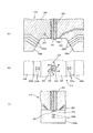
図7は、紡糸ヘッド210の変形例を示している。図7(A)は、変形例に係る紡糸ヘッド210の断面図であり、図7(B)は、変形例に係る紡糸ヘッド210を下側から見た図であり、図7(C)は、変形例に係る紡糸ヘッド210の図7(A)に対して垂直な方向の断面図である。
FIG. 7 shows a modified example of the spinning
図7(A)〜(C)に示されるように、変形例に係る紡糸ヘッド210においては、複数の小孔203が紡糸ノズル部205(紡糸ノズル201)を円形に囲むように配置されている。各小孔203は、水平面に対して僅かに傾斜して形成されており、各小孔203からは、図7(B)における矢印方向に高温のエアーが噴出される。このような複数の小孔203から高温のエアーを噴出させることによってもフィラメント211の紡糸が安定する。
As shown in FIGS. 7A to 7C, in the spinning
上述のように、製造された横配列長繊維不織布を構成するフィラメントの平均繊維径は1〜4μm(好ましくは、2〜3μm)であり、製造された縦配列長繊維不織布18を構成するフィラメントの繊維径分布の変動係数は0.1〜0.3である。また、製造された横配列長繊維不織布は、繊維の方向、すなわち、長繊維フィラメントの軸方向であり且つ延伸方向である横方向への伸び率が、1〜20%であり、好ましくは5〜15%である。すなわち、横配列長繊維不織布は、横方向に伸縮性を有するものであり得る。また、製造された横配列長繊維不織布の横方向への引張強度は、5N/50mm以上、好ましくは10N/50mm以上、さらに好ましくは20N/50mm以上である。
As described above, the average fiber diameter of the filaments constituting the manufactured transversely arranged long fiber nonwoven fabric is 1 to 4 μm (preferably 2 to 3 μm), and the filaments constituting the manufactured longitudinally arranged long
[直交配列不織布]
直交配列不織布は、基本的には、(1)前記縦配列長繊維不織布と前記横配列長繊維不織布とを積層し且つ融着して形成され、(2)二つの前記縦配列長繊維不織布のうちの一方を90°回転させて積層し且つ融着して形成され、又は、(3)二つの前記横配列長繊維不織布のうちの一方を90°回転させて積層し且つ融着して形成される。但し、これらに限られるものではなく、例えば、(4)前記縦配列長繊維不織布と、目付が前記横配列長繊維不織布と同等で且つ構成繊維の平均繊維径が前記横配列長繊維不織布のそれよりも大きい横配列長繊維不織布とを積層し且つ融着して形成されてもよい。なお、融着は、特に制限されるものではないが、一般的にはエンボスロール等を使用した熱圧着によって行われる。
[Orthogonal non-woven fabric]
The orthogonally arranged nonwoven fabric is basically formed by laminating and fusing (1) the vertically arranged long fiber nonwoven fabric and the horizontally arranged long fiber nonwoven fabric, and (2) forming the two vertically arranged long fiber nonwoven fabrics. One of them is rotated 90 ° to be laminated and fused to form, or (3) one of the two transversely arranged long fiber nonwoven fabrics is rotated 90 ° to be laminated and fused to be formed. Will be done. However, the present invention is not limited to these. It may be formed by laminating and fusing a larger transversely arranged long fiber non-woven fabric. The fusion is not particularly limited, but is generally performed by thermocompression bonding using an embossed roll or the like.
[不織布積層体]
前記不織布積層体は、基本的には、複数の前記縦配列長繊維不織布が厚さ方向に積み重ねられて構成され、複数の前記横配列長繊維不織布が厚さ方向に積み重ねられて構成され又は複数の前記直交配列不織布が厚さ方向に積み重ねられて構成され得る。但し、これらに限られるものではなく、前記不織布積層体は、前記縦配列長繊維不織布と前記横配列長繊維不織布と前記直交配列不織布との任意の組み合わせによっても構成され得る。
[Non-woven fabric laminate]
The nonwoven fabric laminate is basically configured by stacking a plurality of the longitudinally arranged nonwoven fabrics in the thickness direction, and is configured by stacking a plurality of the transversely arranged nonwoven fabrics in the thickness direction or a plurality of the nonwoven fabrics. The orthogonally arranged nonwoven fabrics of the above can be stacked and configured in the thickness direction. However, the non-woven fabric laminate is not limited to these, and the nonwoven fabric laminate may be composed of any combination of the longitudinally arranged long fiber nonwoven fabric, the horizontally arranged nonwoven fabric, and the orthogonally arranged nonwoven fabric.
以下、本発明による不織布製吸音材を実施例により説明する。但し、本発明は、以下の実施例によって限定されるものではない。 Hereinafter, the nonwoven fabric sound absorbing material according to the present invention will be described by way of examples. However, the present invention is not limited to the following examples.
[長繊維不織布]
図3に示された製造装置を用いて縦配列長繊維不織布を作製した。メルトブローダイスとしては、ノズル径が0.15mm、ノズルピッチが0.5mm、L/D(ノズル孔長/ノズル孔直径)=20、紡糸幅が500mmの紡糸ノズルを有するものを用い、これをコンベアベルトの走行方向と垂直に配置した。フィラメントの原料(熱可塑性樹脂)としては、固有粘度IVが0.53、融点が260℃のポリエチレンテレフタレート(CHUNG SHING TEXTILE CO.,LTD.)を用いた。1ノズル当たりの吐出量を40g/min、ダイスの温度を295℃として前記メルトブローダイスからフィラメントを押し出した。ノズルから押し出されたフィラメントにドラフトをかけて細径化するための高速気流は、温度を400℃、流量を0.4m3/minとした。また、スプレーノズルからは霧状の水を噴霧してフィラメントを冷却した。気流振動機構は、メルトブローダイスのノズルの延長線との距離が最小で20mmとなるように配置した。気流振動機構を900rpm(気流振動機構の周壁面での振動数が15.0Hz)で回転させ、フィラメントを縦方向に沿って配列させた状態でコンベアベルト上に捕集した。コンベアベルト上に捕集されたフィラメントを延伸シリンダで加熱し、縦方向に4.5倍に延伸して縦配列長繊維不織布とした。そして、コンベアベルトの走行速度を適宜変化させることによって、目付が5〜40g/m2の縦配列長繊維不織布を得た。なお、ここでは、目付が5〜40g/m2の縦配列長繊維不織布を作製したが、コンベアベルトの走行速度を変化させることによって、目付が60g/m2までの縦配列長繊維不織布を作製できることが確認されている。
[Long fiber non-woven fabric]
A longitudinally arranged long fiber non-woven fabric was produced using the manufacturing apparatus shown in FIG. As the melt blow die, a nozzle having a nozzle diameter of 0.15 mm, a nozzle pitch of 0.5 mm, L / D (nozzle hole length / nozzle hole diameter) = 20, and a spinning width of 500 mm is used, and this is used as a conveyor. It was placed perpendicular to the running direction of the belt. As a raw material (thermoplastic resin) for the filament, polyethylene terephthalate (CHUNG SHING TEXTILE CO., LTD.) With an intrinsic viscosity IV of 0.53 and a melting point of 260 ° C. was used. The filament was extruded from the melt blow die with a discharge rate of 40 g / min per nozzle and a die temperature of 295 ° C. The high-speed airflow for drafting the filament extruded from the nozzle to reduce the diameter was set to a temperature of 400 ° C. and a flow rate of 0.4 m 3 / min. In addition, atomized water was sprayed from the spray nozzle to cool the filament. The airflow vibration mechanism was arranged so that the distance from the extension line of the nozzle of the melt blow die was at least 20 mm. The airflow vibration mechanism was rotated at 900 rpm (the frequency of the airflow vibration mechanism on the peripheral wall surface was 15.0 Hz), and the filaments were collected on the conveyor belt in a state of being arranged along the vertical direction. The filament collected on the conveyor belt was heated by a stretching cylinder and stretched 4.5 times in the vertical direction to obtain a vertically arranged long fiber non-woven fabric. Then, by appropriately changing the traveling speed of the conveyor belt, a vertically arranged long fiber non-woven fabric having a basis weight of 5 to 40 g / m 2 was obtained. Here, a longitudinally arranged long fiber non-woven fabric having a grain size of 5 to 40 g / m 2 was produced, but by changing the traveling speed of the conveyor belt, a vertically arranged long fiber non-woven fabric having a grain size of up to 60 g / m 2 was produced. It has been confirmed that it can be done.
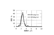
得られた縦配列長繊維不織布の物性を図8に示す。また、目付が10g/m2の縦配列長繊維不織布と目付が20g/m2の縦配列長繊維不織布の繊維径分布を図9に示す。図6に示されるように、いずれの縦配列長繊維不織布においても、その繊維径分布の最頻値は約2.5μmであり、平均繊維径も約2.5μmであった。なお、作製時におけるコンベアベルトの走行速度が異なるだけであるので、繊維径分布の最頻値及び平均繊維径は、目付が5〜60g/m2の縦配列長繊維不織布について図9とほぼ同じになると考えられる。 The physical characteristics of the obtained longitudinally arranged long fiber nonwoven fabric are shown in FIG. Further, FIG. 9 shows the fiber diameter distribution of the vertically arranged long fiber nonwoven fabric having a grain of 10 g / m 2 and the vertically arranged long fiber nonwoven fabric having a grain of 20 g / m 2. As shown in FIG. 6, in any of the vertically arranged long fiber nonwoven fabrics, the mode of the fiber diameter distribution was about 2.5 μm, and the average fiber diameter was also about 2.5 μm. Since the running speed of the conveyor belt at the time of production is different, the mode and average fiber diameter of the fiber diameter distribution are almost the same as those of FIG. 9 for the vertically arranged long fiber nonwoven fabric having a grain size of 5 to 60 g / m 2. Is thought to be.
(実施例1)
目付が15g/m2の縦配列長繊維不織布を100枚積み重ねた不織布積層体を実施例1とした。具体的には、目付が15g/m2の縦配列長繊維不織布を単に100枚積み重ねただけの不織布積層体(非圧縮状態の不織布積層体、厚さ:約12mm)を実施例1−1とし、実施例1−1に対して厚さ方向に圧縮した状態の積層体(圧縮状態の不織布積層体、厚さ:約8mm)を実施例1−2とした。
(Example 1)
Example 1 was a non-woven fabric laminate in which 100 sheets of vertically arranged long fiber non-woven fabric having a basis weight of 15 g / m 2 were stacked. Specifically, Example 1-1 is a non-woven fabric laminate (non-compressed non-woven fabric laminate, thickness: about 12 mm) in which 100 sheets of vertically arranged long fiber non-woven fabric having a grain size of 15 g / m 2 are simply stacked. A laminate in a state of being compressed in the thickness direction with respect to Example 1-1 (a non-woven fabric laminate in a compressed state, thickness: about 8 mm) was designated as Example 1-2.
(実施例2)
目付が15g/m2の縦配列長繊維不織布を200枚積み重ねた不織布積層体を実施例2とした。具体的には、目付が15g/m2の縦配列長繊維不織布を単に200枚積み重ねただけの不織布積層体(非圧縮状態の不織布積層体、厚さ:約22mm)を実施例2−1とし、実施例2−1に対して厚さ方向に圧縮した状態の積層体(圧縮状態の不織布積層体、厚さ:約14mm)を実施例2−2とした。
(Example 2)
Example 2 was a non-woven fabric laminate in which 200 sheets of vertically arranged long fiber non-woven fabric having a basis weight of 15 g / m 2 were stacked. Specifically, Example 2-1 is a non-woven fabric laminate (non-compressed non-woven fabric laminate, thickness: about 22 mm) in which 200 sheets of vertically arranged long fiber non-woven fabric having a grain size of 15 g / m 2 are simply stacked. A laminate in a state compressed in the thickness direction with respect to Example 2-1 (compressed nonwoven fabric laminate, thickness: about 14 mm) was designated as Example 2-2.
(実施例3)
目付が20g/m2の縦配列長繊維不織布を複数枚積み重ねた不織布積層体を実施例3とした。具体的には、目付が20g/m2の縦配列長繊維不織布を50枚積み重ねた不織布積層体を実施例3−1とし、目付が20g/m2の縦配列長繊維不織布を100枚積み重ねた不織布積層体を実施例3−2とし、目付が20g/m2の縦配列長繊維不織布を200枚積み重ねた不織布積層体を実施例3−3とした。
(Example 3)
Example 3 was a nonwoven fabric laminate in which a plurality of vertically arranged long fiber nonwoven fabrics having a basis weight of 20 g / m 2 were stacked. Specifically, the basis weight is the vertical arrangement long-
(比較例、参考例)
市販の不織布製吸音材(3M社製、商品名「シンサレート」,TAI−2047,目付:200g/m2,厚さ:10mm)を比較例とした。また、目付が20g/m2の縦配列長繊維不織布を20枚積み重ねた不織布積層体を参考例とした。
(Comparative example, reference example)
A commercially available non-woven sound absorbing material (manufactured by 3M, trade name "Thinsulate", TAI-2047, basis weight: 200 g / m 2 , thickness: 10 mm) was used as a comparative example. Further, a nonwoven fabric laminate in which 20 sheets of vertically arranged long fiber nonwoven fabrics having a basis weight of 20 g / m 2 were stacked was used as a reference example.
[吸音試験]
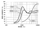
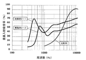
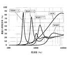
日本音響エンジニアリング社製の垂直入射吸音率測定システムWinZacMTXを用いて、実施例1、実施例2、実施例3、参考例及び比較例のそれぞれについてJIS A1405−2に規定されている垂直入射吸音率を測定した。図10は、実施例1と比較例の垂直入射吸音率の測定結果を示し、図11は、実施例2と比較例の垂直入射吸音率の測定結果を示し、図12は、実施例3、参考例及び比較例の垂直入射吸音率の測定結果を示す。なお、図10及び図11における比較例の測定結果と図12における比較例の測定結果とがわずかに異なっているが、これはシステムの測定ばらつきによるものである。
[Sound absorption test]
Using the vertical incident sound absorption coefficient measurement system WinZacMTX manufactured by Nippon Acoustic Engineering Co., Ltd., the vertical incident sound absorption coefficient specified in JIS A1405-2 for each of Example 1, Example 2, Example 3, Reference Example and Comparative Example. Was measured. FIG. 10 shows the measurement results of the vertical incident sound absorption coefficient of Example 1 and Comparative Example, FIG. 11 shows the measurement results of the vertical incident sound absorption coefficient of Example 2 and Comparative Example, and FIG. 12 shows the measurement results of Example 3 and Comparative Example. The measurement results of the vertical incident sound absorption coefficient of the reference example and the comparative example are shown. The measurement results of the comparative examples in FIGS. 10 and 11 and the measurement results of the comparative examples in FIG. 12 are slightly different, but this is due to the measurement variation of the system.
図10に示されるように、実施例1(実施例1−1、1−2)は、概ね4000Hz以下の所定の周波数帯域において比較例に比べて垂直入射吸音率が高く、図11に示されるように、実施例2(実施例2−1、2−2)は、概ね3000Hz以下の所定の周波数帯域において比較例に比べて垂直入射吸音率が高い。また、図12に示されるように、実施例3(実施例3−1、3−2、3−2)は、概ね2000Hz以下の所定の周波数帯域において比較例に比べて垂直入射吸音率が高いことが確認された。 As shown in FIG. 10, Example 1 (Examples 1-1 and 1-2) has a higher vertical incident sound absorption coefficient than the comparative example in a predetermined frequency band of about 4000 Hz or less, and is shown in FIG. As described above, in Example 2 (Examples 2-1 and 2-2), the vertical incident sound absorption coefficient is higher than that in the comparative example in a predetermined frequency band of about 3000 Hz or less. Further, as shown in FIG. 12, Example 3 (Examples 3-1, 3-2, 3-2) has a higher vertical incident sound absorption coefficient than the comparative example in a predetermined frequency band of about 2000 Hz or less. It was confirmed that.
また、図10〜図12に示されるように、実施例1〜3は、いずれも2000Hz以下の周波数において垂直入射吸音率が50%以上である垂直入射吸音率のピークを有することが確認された。具体的には、実施例1は、900〜2000Hzに垂直入射吸音率が50%以上である垂直入射吸音率のピークを有し、実施例2は、400〜1000Hzに垂直入射吸音率が50%以上である垂直入射吸音率のピークを有し、実施例3は、300〜2000Hzに垂直入射吸音率が50%以上である垂直入射吸音率のピークを有することが確認された。 Further, as shown in FIGS. 10 to 12, it was confirmed that all of Examples 1 to 3 had a peak of the vertical incident sound absorption coefficient having a vertical incident sound absorption coefficient of 50% or more at a frequency of 2000 Hz or less. .. Specifically, Example 1 has a peak of the vertical incident sound absorption coefficient of 50% or more at 900 to 2000 Hz, and Example 2 has a vertical incident sound absorption coefficient of 50% at 400 to 1000 Hz. It was confirmed that Example 3 had the peak of the vertical incident sound absorption coefficient as described above, and that Example 3 had the peak of the vertical incident sound absorption coefficient of 50% or more at 300 to 2000 Hz.
さらに、図12に示されるように、前記不織布積層体を構成する前記縦配列長繊維不織布の枚数(積層枚数)が多いほど、垂直入射吸音率のピークが低周波数側にシフトすること、及び、より狭い周波数範囲においてより高い垂直入射吸音率が得られることが確認された。したがって、例えば、吸音すべき音の周波数をあらかじめ測定し、測定された周波数に応じて不織布積層体を構成する縦配列長繊維不織布の枚数などを調整することによって、個別に最適な吸音材を形成することも可能である。 Further, as shown in FIG. 12, as the number of the vertically arranged long fiber nonwoven fabrics constituting the nonwoven fabric laminate is larger (the number of laminated fabrics), the peak of the vertically incident sound absorption coefficient shifts to the low frequency side, and It was confirmed that a higher vertical incident sound absorption coefficient can be obtained in a narrower frequency range. Therefore, for example, by measuring the frequency of the sound to be absorbed in advance and adjusting the number of vertically arranged long fiber nonwoven fabrics constituting the nonwoven fabric laminate according to the measured frequency, the optimum sound absorbing material is individually formed. It is also possible to do.
本発明による吸音材用不織布を含む吸音材は、様々な場所において使用され得る。例えば、本発明による吸音材用不織布を含む吸音材は、自動車のエンジンルーム用吸音材や内装用吸音材として、自動車や家電製品や各種モータなどの吸音保護材として、各種建築物の壁、床又は天井などに設置される吸音材として、機械室などの内装用吸音材として、各種防音壁の吸音材として、及び/又は、コピー機や複合機などのOA機器用の吸音材として、使用され得る。 The sound absorbing material including the non-woven fabric for sound absorbing material according to the present invention can be used in various places. For example, the sound absorbing material including the non-woven fabric for sound absorbing material according to the present invention can be used as a sound absorbing material for an automobile engine room or an interior sound absorbing material, as a sound absorbing protective material for automobiles, home appliances, various motors, etc., on walls and floors of various buildings. Or, it is used as a sound absorbing material installed on the ceiling, etc., as a sound absorbing material for interiors such as machine rooms, as a sound absorbing material for various soundproof walls, and / or as a sound absorbing material for OA equipment such as copying machines and compound machines. obtain.
51 長繊維不織布
52 不織布積層体
53 包装体
51 Long
Claims (8)
Priority Applications (4)
| Application Number | Priority Date | Filing Date | Title |
|---|---|---|---|
| EP17873487.7A EP3547306B1 (en) | 2016-11-28 | 2017-11-28 | Sound absorbing material comprising non-woven fabric |
| US16/462,761 US20200058282A1 (en) | 2016-11-28 | 2017-11-28 | Nonwoven Sound Absorbing Material |
| PCT/JP2017/042684 WO2018097327A1 (en) | 2016-11-28 | 2017-11-28 | Sound absorbing material comprising non-woven fabric |
| CN201780073216.2A CN109997184A (en) | 2016-11-28 | 2017-11-28 | Non-woven sound absorbing material |
Applications Claiming Priority (2)
| Application Number | Priority Date | Filing Date | Title |
|---|---|---|---|
| JP2016230411 | 2016-11-28 | ||
| JP2016230411 | 2016-11-28 |
Publications (2)
| Publication Number | Publication Date |
|---|---|
| JP2018092132A JP2018092132A (en) | 2018-06-14 |
| JP6968614B2 true JP6968614B2 (en) | 2021-11-17 |
Family
ID=62565554
Family Applications (1)
| Application Number | Title | Priority Date | Filing Date |
|---|---|---|---|
| JP2017154344A Active JP6968614B2 (en) | 2016-11-28 | 2017-08-09 | Non-woven sound absorbing material |
Country Status (4)
| Country | Link |
|---|---|
| US (1) | US20200058282A1 (en) |
| EP (1) | EP3547306B1 (en) |
| JP (1) | JP6968614B2 (en) |
| CN (1) | CN109997184A (en) |
Families Citing this family (3)
| Publication number | Priority date | Publication date | Assignee | Title |
|---|---|---|---|---|
| JP2018092131A (en) * | 2016-11-28 | 2018-06-14 | Jxtgエネルギー株式会社 | Non-woven fabric for sound absorbing material and sound absorbing material using the same |
| US11929054B2 (en) | 2018-08-02 | 2024-03-12 | Maxell, Ltd. | Soundproof material |
| JP7140668B2 (en) * | 2018-12-17 | 2022-09-21 | 株式会社ブリヂストン | pneumatic tire |
Family Cites Families (14)
| Publication number | Priority date | Publication date | Assignee | Title |
|---|---|---|---|---|
| DE2004558B2 (en) * | 1969-02-03 | 1975-03-27 | Teijin Ltd., Osaka (Japan) | Method for stretching polyester threads |
| JP2000334867A (en) * | 1999-05-31 | 2000-12-05 | Nippon Petrochem Co Ltd | LAMINATE, STRUCTURE HAVING THE LAMINATE, METHOD OF MANUFACTURING THE LAMINATE, AND METHOD OF MANUFACTURING THE STRUCTURE |
| US6548431B1 (en) * | 1999-12-20 | 2003-04-15 | E. I. Du Pont De Nemours And Company | Melt spun polyester nonwoven sheet |
| JP2003286649A (en) * | 2002-03-26 | 2003-10-10 | Nippon Petrochemicals Co Ltd | Method for producing web in which filaments are arranged in one direction and apparatus for producing the web |
| JP2004076237A (en) * | 2002-08-22 | 2004-03-11 | Nippon Petrochemicals Co Ltd | Reinforced stretch nonwoven |
| JP4433295B2 (en) * | 2004-07-05 | 2010-03-17 | 東洋紡績株式会社 | Spunbond nonwoven fabric and sound deadening material suitable for sound-absorbing material base fabric |
| JP2008036880A (en) * | 2006-08-02 | 2008-02-21 | Daiwabo Co Ltd | Laminated nonwoven fabric, gelled sheet and filler fixed sheet |
| JP2009275801A (en) * | 2008-05-14 | 2009-11-26 | Nippon Oil Corp | Vacuum insulation material and its manufacturing method |
| EP2425965B1 (en) * | 2009-04-30 | 2018-10-10 | Asahi Kasei Kabushiki Kaisha | Laminated non-woven fabric |
| JP5661333B2 (en) * | 2010-05-26 | 2015-01-28 | Jx日鉱日石エネルギー株式会社 | Unidirectional stretch base material, composite stretch sheet, and production method thereof |
| JP5626995B2 (en) * | 2011-02-15 | 2014-11-19 | 株式会社神戸製鋼所 | Sound absorption panel |
| US8496088B2 (en) * | 2011-11-09 | 2013-07-30 | Milliken & Company | Acoustic composite |
| JP6123886B2 (en) * | 2013-04-26 | 2017-05-10 | 株式会社オートネットワーク技術研究所 | Wire harness with sound absorbing material |
| US9309612B2 (en) * | 2014-05-07 | 2016-04-12 | Biax-Fiberfilm | Process for forming a non-woven web |
-
2017
- 2017-08-09 JP JP2017154344A patent/JP6968614B2/en active Active
- 2017-11-28 US US16/462,761 patent/US20200058282A1/en not_active Abandoned
- 2017-11-28 CN CN201780073216.2A patent/CN109997184A/en active Pending
- 2017-11-28 EP EP17873487.7A patent/EP3547306B1/en active Active
Also Published As
| Publication number | Publication date |
|---|---|
| CN109997184A (en) | 2019-07-09 |
| US20200058282A1 (en) | 2020-02-20 |
| JP2018092132A (en) | 2018-06-14 |
| EP3547306A4 (en) | 2020-07-15 |
| EP3547306A1 (en) | 2019-10-02 |
| EP3547306B1 (en) | 2022-10-12 |
Similar Documents
| Publication | Publication Date | Title |
|---|---|---|
| US6524521B1 (en) | Method of and apparatus for manufacturing longitudinally aligned nonwoven fabric | |
| JP6811685B2 (en) | Sound absorbing material | |
| JP2001098455A (en) | Horizontally-aligned web, method and apparatus for manufacturing horizontal-aligned web | |
| JP6968614B2 (en) | Non-woven sound absorbing material | |
| CN101305118A (en) | Method for producing three-dimensionally crimped sheath-core staple fiber and such sheath-core staple fiber | |
| EP3547307B1 (en) | Nonwoven fabric for sound-absorbing material and sound-absorbing material using same | |
| WO2015141495A1 (en) | Method for manufacturing ultrafine fiber | |
| JP2002249969A (en) | Method and apparatus for manufacturing transversely arranged web | |
| JP5305961B2 (en) | Extra fine fiber nonwoven fabric | |
| JP6694241B2 (en) | Stretchable long-fiber non-woven fabric | |
| WO2018097326A1 (en) | Nonwoven fabric for sound-absorbing material and sound-absorbing material using same | |
| JP5305960B2 (en) | Manufacturing method of ultra-fine fiber nonwoven fabric and manufacturing apparatus thereof | |
| JP6716380B2 (en) | Long fiber non-woven fabric | |
| JP7333189B2 (en) | sound absorbing material | |
| JP2002110132A (en) | Non-woven fabric for battery separator | |
| WO2018097327A1 (en) | Sound absorbing material comprising non-woven fabric | |
| JP7419637B2 (en) | Melt-blown nonwoven fabric and its manufacturing method | |
| JP7427435B2 (en) | Long fiber nonwoven fabric | |
| JP3581712B2 (en) | Stretched melt-blown fibers, methods for making such fibers, and webs made from such fibers | |
| JP2006296463A (en) | Curtain base fabric and curtain | |
| JP2003278070A (en) | Method for producing web in which filaments are arranged in one direction and apparatus for producing the web | |
| JP2020121289A (en) | Network structure for dust collection | |
| WO2017068811A1 (en) | Nanofiber nonwoven cloth and sound-absorbing member using same | |
| JP2003286653A (en) | Method for producing web in which filaments are arranged in one direction and apparatus for producing the web |
Legal Events
| Date | Code | Title | Description |
|---|---|---|---|
| A621 | Written request for application examination |
Free format text: JAPANESE INTERMEDIATE CODE: A621 Effective date: 20200312 |
|
| A131 | Notification of reasons for refusal |
Free format text: JAPANESE INTERMEDIATE CODE: A131 Effective date: 20210514 |
|
| A521 | Request for written amendment filed |
Free format text: JAPANESE INTERMEDIATE CODE: A523 Effective date: 20210706 |
|
| TRDD | Decision of grant or rejection written | ||
| A01 | Written decision to grant a patent or to grant a registration (utility model) |
Free format text: JAPANESE INTERMEDIATE CODE: A01 Effective date: 20211001 |
|
| A61 | First payment of annual fees (during grant procedure) |
Free format text: JAPANESE INTERMEDIATE CODE: A61 Effective date: 20211027 |
|
| R150 | Certificate of patent or registration of utility model |
Ref document number: 6968614 Country of ref document: JP Free format text: JAPANESE INTERMEDIATE CODE: R150 |
|
| S111 | Request for change of ownership or part of ownership |
Free format text: JAPANESE INTERMEDIATE CODE: R313111 |
|
| R350 | Written notification of registration of transfer |
Free format text: JAPANESE INTERMEDIATE CODE: R350 |
|
| R250 | Receipt of annual fees |
Free format text: JAPANESE INTERMEDIATE CODE: R250 |
|
| R250 | Receipt of annual fees |
Free format text: JAPANESE INTERMEDIATE CODE: R250 |