JP6966327B2 - Cutting tools, cutting inserts and cutting tool holders - Google Patents
Cutting tools, cutting inserts and cutting tool holders Download PDFInfo
- Publication number
- JP6966327B2 JP6966327B2 JP2017553174A JP2017553174A JP6966327B2 JP 6966327 B2 JP6966327 B2 JP 6966327B2 JP 2017553174 A JP2017553174 A JP 2017553174A JP 2017553174 A JP2017553174 A JP 2017553174A JP 6966327 B2 JP6966327 B2 JP 6966327B2
- Authority
- JP
- Japan
- Prior art keywords
- insert
- cutting
- fastening
- cutting insert
- fastening member
- Prior art date
- Legal status (The legal status is an assumption and is not a legal conclusion. Google has not performed a legal analysis and makes no representation as to the accuracy of the status listed.)
- Active
Links
Images


Classifications
-
- B—PERFORMING OPERATIONS; TRANSPORTING
- B23—MACHINE TOOLS; METAL-WORKING NOT OTHERWISE PROVIDED FOR
- B23B—TURNING; BORING
- B23B27/00—Tools for turning or boring machines; Tools of a similar kind in general; Accessories therefor
- B23B27/14—Cutting tools of which the bits or tips or cutting inserts are of special material
- B23B27/16—Cutting tools of which the bits or tips or cutting inserts are of special material with exchangeable cutting bits or cutting inserts, e.g. able to be clamped
- B23B27/1662—Cutting tools of which the bits or tips or cutting inserts are of special material with exchangeable cutting bits or cutting inserts, e.g. able to be clamped with plate-like cutting inserts clamped against the walls of the recess in the shank by a clamping member acting upon the wall of a hole in the cutting insert
-
- B—PERFORMING OPERATIONS; TRANSPORTING
- B23—MACHINE TOOLS; METAL-WORKING NOT OTHERWISE PROVIDED FOR
- B23C—MILLING
- B23C5/00—Milling-cutters
- B23C5/16—Milling-cutters characterised by physical features other than shape
- B23C5/20—Milling-cutters characterised by physical features other than shape with removable cutter bits or teeth or cutting inserts
- B23C5/22—Securing arrangements for bits or teeth or cutting inserts
- B23C5/2204—Securing arrangements for bits or teeth or cutting inserts with cutting inserts clamped against the walls of the recess in the cutter body by a clamping member acting upon the wall of a hole in the insert
- B23C5/2208—Securing arrangements for bits or teeth or cutting inserts with cutting inserts clamped against the walls of the recess in the cutter body by a clamping member acting upon the wall of a hole in the insert for plate-like cutting inserts
- B23C5/2213—Securing arrangements for bits or teeth or cutting inserts with cutting inserts clamped against the walls of the recess in the cutter body by a clamping member acting upon the wall of a hole in the insert for plate-like cutting inserts having a special shape
-
- B—PERFORMING OPERATIONS; TRANSPORTING
- B23—MACHINE TOOLS; METAL-WORKING NOT OTHERWISE PROVIDED FOR
- B23B—TURNING; BORING
- B23B2205/00—Fixation of cutting inserts in holders
- B23B2205/04—Fixation screws, bolts or pins of particular form
- B23B2205/045—Fixation screws, bolts or pins of particular form orientated obliquely to the hole in the insert or to the seating surface
-
- B—PERFORMING OPERATIONS; TRANSPORTING
- B23—MACHINE TOOLS; METAL-WORKING NOT OTHERWISE PROVIDED FOR
- B23C—MILLING
- B23C2210/00—Details of milling cutters
- B23C2210/16—Fixation of inserts or cutting bits in the tool
- B23C2210/165—Fixation bolts
Description
本願の主題は、切削工具の分野にあり、特に切削工具ホルダの上への切削インサートの取り付け機構及び固着機構の分野にある。 The subject of the present application is in the field of cutting tools, especially in the field of mounting and fixing mechanisms of cutting inserts on cutting tool holders.
切削工具は、概して少なくとも1つの切れ刃で形成され、切れ刃をワークピースと接触させ、ワークピースに関して切削工具を動かす又はその逆のどちらかによってワークピースに関して切れ刃を動かすことによるワークピースからの材料の除去に適応される。 A cutting tool is generally formed of at least one cutting edge, from a workpiece by contacting the cutting edge with the workpiece and moving the cutting tool with respect to the workpiece by moving the cutting tool with respect to the workpiece or vice versa. Adapted to material removal.
切削工具の切れ刃は、切削操作に使用されるとき、特に金属等の固い材料を切削するときに急速に摩耗し、従って、切れ刃は頻繁に交換又は研ぎ直されなければならない。例えばフライス盤/ボール盤/旋盤に適応された工具等、多くのタイプの切削工具では、切削工具は、それぞれが少なくとも1つの切れ刃で形成される複数の切削インサートを含んでよく、当該インサートは、切削工具を形成するために切削工具ホルダのシートの中に固定される。 The cutting edge of a cutting tool wears rapidly when used in cutting operations, especially when cutting hard materials such as metal, so the cutting edge must be frequently replaced or re-sharpened. In many types of cutting tools, such as tools adapted to milling machines / drilling machines / lathes, the cutting tool may include multiple cutting inserts, each formed of at least one cutting edge, the insert being cutting. Fixed in the sheet of the cutting tool holder to form the tool.
従来の切削工具では、切削インサートは、切削インサートの穴を通って切削工具のシートの底部の中に入る締結具によって切削工具のシートの中に取り付けられる。別の切れ刃(又は完全に別のインサート)の使用を可能にするために切削インサートを間欠駆動する(又は完全に交換する)には、締結具の除去、切削インサートの再配向又は除去、及び締結具による切削工具のシートの中での切削インサートの再取り付けを必要とする。これらの操作のそれぞれは時間及び労力を伴い、切削工具は概して複数のそうした切削インサートを含むため、切削工具で切削インサートを間欠駆動することに関わる時間及び労務費は多大である。 In a conventional cutting tool, the cutting insert is attached into the sheet of the cutting tool by a fastener that enters the bottom of the sheet of the cutting tool through the hole in the cutting insert. To intermittently drive (or completely replace) a cutting insert to allow the use of another cutting edge (or a completely different insert), fastener removal, reorientation or removal of the cutting insert, and Requires reattachment of the cutting insert in the sheet of the cutting tool with fasteners. Each of these operations is time consuming and labor intensive, and since the cutting tool generally contains more than one such cutting insert, the time and labor costs associated with intermittently driving the cutting insert with the cutting tool are significant.
その内の1つが上記に示されている技術的な問題を解決するために、切削インサートを切削工具ホルダに取り付けるための代替方法は、出願人に対する国際公開公報第WO2008/149371号に開示されるように考案されている。 An alternative method for attaching a cutting insert to a cutting tool holder, one of which is to solve the technical problem set forth above, is disclosed in WO 2008/149371 to Applicants. It is devised as.
切削インサートを切削工具ホルダの上に締結する他の方法は、通常は、切削インサートの指定された表面と接触するために動かし、切削インサートを固定する目的でその上に圧力を付加するために構成された少なくとも1つの可動部を含むメカニックアセンブリの形をとるクランプ及びレバー機構の使用を含む。そうした構成の例は米国特許第3027623A号、米国特許第3138846A号及び他に開示されている。 Other methods of fastening the cutting insert onto the cutting tool holder are usually configured to move to contact the specified surface of the cutting insert and apply pressure on it for the purpose of fixing the cutting insert. Includes the use of clamp and lever mechanisms in the form of mechanic assemblies that include at least one moving part. Examples of such configurations are disclosed in US Pat. No. 3,207,623A, US Pat. No. 3,138,846A and others.
追加の例は、切削インサートの取り付け及び取り外しの間、締結ネジが工具ホルダと係合したままである構成を開示する欧州特許第0037554号、米国特許第3,341,919号、米国特許第3,805,351号、米国特許第3,913,197号、米国特許第3,946,473号、及び米国特許第5,199,828号を含む。 Additional examples are European Patent No. 0037554, US Pat. No. 3,341,919, US Pat. No. 3, which discloses a configuration in which the fastening screw remains engaged with the tool holder during the installation and removal of the cutting insert. , 805,351, US Pat. No. 3,913,197, US Pat. No. 3,946,473, and US Pat. No. 5,199,828.
本明細書での上記参考文献の認識は、これらがいかなる形であれ本開示主題の特許性に関連することを意味するとして推測されるべきではない。 The recognition of the above references herein should not be presumed to mean that they are in any way related to the patentability of the disclosed subject matter.
本願の主題の第1態様に従って、1が提供される。切削工具ホルダの上に切削インサートを取り付けて切削工具を形成するために構成された切削工具ホルダであって、当該切削インサートは、上面、底面、上面と底面との間に延在する少なくとも1つの側壁、及び、上面と底面との間に延在するインサートボアを有し、前記切削工具ホルダは本体及び締結部材を備え、前記本体は、
ベース面を有し、その中に切削インサートを受け入れるために構成されたインサートシートと、
前記ベース面に開放端部を有するシートボアと、を備え、
前記締結部材は、締結部材軸を規定し、シャンク部分及びそれに沿って延在するヘッド部分を含み、
前記シャンク部分は、前記シートボアの中に受け入れられるために構成され、
前記ヘッド部分は、第1クランプ領域と、そこから軸方向に離間され、シャンク部分と第1クランプ領域との間に配置される第2クランプ領域と、を含み、
前記締結部材は、前記締結部材が切削インサートをインサートシートの中に位置決めすることを可能にしつつ、シートボアと係合したままとなる取り付け位置、並びに、前記第1クランプ領域及び前記第2クランプ領域が前記切削インサートの2つの軸方向に離間された領域と係合し、それによって切削インサートをインサートシートに固定するために配置される固定位置をとるために構成される。
1 is provided according to the first aspect of the subject matter of the present application. A cutting tool holder configured to mount a cutting insert on top of a cutting tool holder to form a cutting tool, the cutting insert being at least one extending between the top, bottom, top and bottom. It has a side wall and an insert bore extending between the top and bottom surfaces, the cutting tool holder comprising a body and a fastening member, and the body.
An insert sheet that has a base surface and is configured to receive a cutting insert in it,
With a seat bore having an open end on the base surface,
The fastening member defines a fastening member axis and includes a shank portion and a head portion extending along the shank portion.
The shank portion is configured to be accommodated in the seat bore.
The head portion comprises a first clamp region and a second clamp region axially spaced from it and located between the shank portion and the first clamp region.
The fastening member has a mounting position in which the fastening member remains engaged with the seat bore while allowing the fastening member to position the cutting insert into the insert sheet, as well as the first clamp area and the second clamp area. It is configured to engage with two axially spaced regions of the cutting insert, thereby taking a fixed position in place to secure the cutting insert to the insert sheet.
本願の主題の別の態様に従って、切削工具ホルダの上に切削インサートを取り付けて切削工具を形成するために構成された切削工具ホルダが提供され、前記切削インサートは、上面、底面、上面と底面との間に延在する少なくとも1つの側壁、及び、上面と底面との間に延在するインサートボアを有し、前記切削工具ホルダは、インサートシートの中に切削インサートを受け入れるために構成されたインサートシート、及び、シートボアの中に締結部材を収容するために構成されたシートボアで形成される本体を含み、前記シートボアは前記ベース面の開放端部及びシートボア軸を有し、前記ホルダは、シートボア軸に対して横断方向に配向された固着軸の回りを回転するために構成されたホルダの本体の中に受け入れられた固着要素も含み、前記ホルダは、シャンク部分及び締結部材軸方向に延在するヘッド部分を含む締結部材も含み、前記シャンク部分は、前記固着要素との固定された係合のために構成され、シートボアとのその係合から自由であり、締結部材が固着軸の回りで旋回移動を実行することができるようにし、前記締結部材のヘッド部分は第1クランプ領域及び第1クランプ領域から軸方向に離間され、シャンク部分により近い第2クランプ領域を含み、前記第1クランプ領域及び前記第2クランプ領域は、前記切削インサートの別個の軸方向に離間された2つの領域を係合するために構成される。 According to another aspect of the subject matter of the present application, a cutting tool holder configured for mounting a cutting insert onto a cutting tool holder to form a cutting tool is provided, wherein the cutting insert is top, bottom, top and bottom. The cutting tool holder has an insert configured to receive a cutting insert in an insert sheet, having at least one side wall extending between the cutting tool holders and an insert bore extending between the top and bottom surfaces. It includes a seat and a body formed of a seat bore configured to accommodate a fastening member in the seat bore, the seat bore having an open end of the base surface and a seat bore shaft, and the holder having a seat bore shaft. Also included is a anchoring element received within the body of the holder configured to rotate around a transversely oriented anchoring shaft, said holder extending axially to the shank portion and fastening member. The shank portion, including the fastening member including the head portion, is configured for a fixed engagement with the anchoring element and is free from its engagement with the seat bore so that the fastening member swivels around the anchoring shaft. Allowing movement to be performed, the head portion of the fastening member is axially separated from the first clamp region and the first clamp region, including a second clamp region closer to the shank portion, the first clamp region and the first clamp region. The second clamp region is configured to engage two distinct axially spaced regions of the cutting insert.
上記構成では、締結部材がシートボアの中に受け入れられるとき、第1クランプ領域は、第2クランプ領域よりも大きい程度までベース面上に隆起している。さらに、シートボア軸は、正の角度で前記インサートシートのベース面に対して曲げられることができ、前記締結部材がシートボアの中に受け入れられるときに第1クランプ領域は第2クランプ領域よりも側壁からより遠く配置される。 In the above configuration, when the fastening member is received in the seat bore, the first clamp region is raised above the base surface to a greater extent than the second clamp region. Further, the seat bore shaft can be bent at a positive angle with respect to the base surface of the insert sheet, and when the fastening member is received into the seat bore, the first clamp region is from the side wall rather than the second clamp region. Placed farther.
切削インサートのインサートボアは、第1クランプ面と、第1クランプ面が切削インサートの上面と第2クランプ面との間で軸方向に挟まれるように第1クランプ面から軸方向に離間された第2クランプ面と、を含む内周で形成され得る。従って、組立て中、第2クランプ面は、第1クランプ面よりもインサートシートのベース面のより近くに配置される。 The insert bore of the cutting insert is axially separated from the first clamp surface so that the first clamp surface and the first clamp surface are axially sandwiched between the upper surface of the cutting insert and the second clamp surface. 2 Can be formed on the inner circumference including the clamp surface. Therefore, during assembly, the second clamp surface is located closer to the base surface of the insert sheet than the first clamp surface.
組立て中、構成は、締結部材の第1クランプ領域が切削インサートの第1クランプ面と係合するために構成され、締結部材の第2クランプ領域は切削インサートの第2クランプ面と係合するために構成されるものである。 During assembly, the configuration is such that the first clamp area of the fastener member engages the first clamp surface of the cutting insert and the second clamp area of the fastener member engages the second clamp surface of the cutting insert. It is composed of.
切削インサートは、切削インサートの上面とその少なくとも1つの側壁との間の交点で規定された切れ刃を備えて形成され得る。組立て中、切削インサートが前記切れ刃を使用し、切削操作を実行するために切削工具ホルダの上に取り付けられるとき、第1クランプ部分と切削インサートとの間の係合は、第2クランプ部分と切削インサートとの間の係合よりも、切削インサートの操作切削隅のより近くに、及び前記ベース面上のより高い高所で起こる。 The cutting insert may be formed with a cutting edge defined at an intersection between the top surface of the cutting insert and at least one side wall thereof. During assembly, when the cutting insert uses the cutting edge and is mounted on the cutting tool holder to perform the cutting operation, the engagement between the first clamp portion and the cutting insert is with the second clamp portion. It occurs closer to the operating cutting corner of the cutting insert and at a higher height on the base surface than the engagement with the cutting insert.
上記に示された本願の主題の両方の態様に従って、締結部材のヘッド部分は、締結部材のヘッド部分上で、切削インサートを切削工具ホルダの上に取り付け、切削工具ホルダから取り除くことを可能にするように設計されることが理解されるべきである。言い換えると、締結部材の刻み込むシリンダの最大直径はつねにインサートボアの中で刻み込まれたシリンダの最大直径以下である。 According to both aspects of the subject matter of the present application set forth above, the head portion of the fastening member allows the cutting insert to be mounted on and removed from the cutting tool holder on the head portion of the fastening member. It should be understood that it is designed to be. In other words, the maximum diameter of the cylinder carved in the fastening member is always less than or equal to the maximum diameter of the cylinder carved in the insert bore.
上記構成は、取り付け位置ででも切削工具ホルダの中に締結部材を保持し、それによって切削インサートの取り付け操作/取り外し操作中に切削工具ホルダから締結部材を切り離す必要を排除する。 The above configuration eliminates the need to hold the fastener in the cutting tool holder even at the mounting position, thereby eliminating the need to disconnect the fastener from the cutting tool holder during the mounting / removing operation of the cutting insert.
一方、ヘッド部分は、上記構成を可能にするために上述されたように、インサートよりも小さい必要があることも理解される。他方、ヘッド部分は、切削インサートをインサートシートに適切に固定するために、切削インサートに下方圧力を付加することができる必要がある。このために、本願の主題の締結部材は、締結部材がベース面に対してある角度をなして配向され、軸方向に離間された2つのクランプ部分を備えて形成される特有の設計を提供する。クランプ部分のそれぞれは、それ自体インサートボアの対応する直径よりも小さい直径の刻み込むシリンダを有するが、締結部材の斜めの向きのために、クランプ部分の垂直突起は切削インサートの別個の軸方向に離間され、対向する2つの領域へ圧力を付加することを可能にする。 On the other hand, it is also understood that the head portion needs to be smaller than the insert, as described above to enable the above configuration. On the other hand, the head portion needs to be able to apply downward pressure to the cutting insert in order to properly secure the cutting insert to the insert sheet. To this end, the fastening members of the subject matter of the present application provide a unique design in which the fastening members are oriented at an angle with respect to the base surface and are formed with two axially spaced clamp portions. .. Each of the clamp parts has a notched cylinder with a diameter smaller than the corresponding diameter of the insert bore itself, but due to the diagonal orientation of the fasteners, the vertical protrusions of the clamp part are separated axially apart from the cutting insert. It makes it possible to apply pressure to two opposing regions.
切削インサートの第1クランプ領域は、インサートボアの中心軸に関する第1クランプ角度で配向されることができ、切削インサートの第2クランプ領域は、第1クランプ角度よりも小さい、インサートボアの中心軸に関する第2クランプ角度で配向されることができる。本構成では、締結部材の締結中、より大きい第1クランプ角度が切削隅に反対の方向で、つまりインサートシートの側壁に向かってヘッド部分に対して横向きの力ベクトルを生じさせる。これは、同様に切削インサートのより安全なクランプにつながる。 The first clamp area of the cutting insert can be oriented at the first clamp angle with respect to the central axis of the insert bore, and the second clamp area of the cutting insert is with respect to the central axis of the insert bore, which is smaller than the first clamp angle. It can be oriented at the second clamp angle. In this configuration, during fastening of the fastening member, a larger first clamp angle produces a lateral force vector with respect to the head portion in the direction opposite to the cutting corner, i.e. towards the side wall of the insert sheet. This also leads to a safer clamp on the cutting insert.
本願の主題の別の態様に従って、中心軸方向に延在し、切削インサートを固定するために切削工具ホルダの中に受け入れられるために構成される締結部材が提供され、前記締結部材は締結部材軸を規定し、ヘッド部分及び前記軸に沿って延在する1つ又は複数のステム部分を含み、前記ヘッド部分は第1クランプ領域及び第2クランプ領域を含み、クランプ領域は締結部材軸に垂直に配向されたそれぞれの平面I及びIIに沿って測定されたそれぞれの最大直径D1及びD2を有し、平面IとIIとの間の距離は締結部材の全体的な軸方向長さの50%を超えない。 According to another aspect of the subject matter of the present application, a fastening member is provided that extends in the direction of the central axis and is configured to be received in a cutting tool holder for fixing a cutting insert, wherein the fastening member is a fastening member shaft. The head portion includes a head portion and one or more stem portions extending along the axis, the head portion includes a first clamp region and a second clamp region, and the clamp region is perpendicular to the fastening member axis. It has the respective maximum diameters D1 and D2 measured along the respective oriented planes I and II, and the distance between the planes I and II is 50% of the overall axial length of the fastener. Do not exceed.
いくつかの設計実施形態に従って、前記軸方向距離は締結部材の本体の全体的な軸方向長さの45%を超えず、より詳細には、前記軸方向距離は締結部材の本体の全体的な軸方向長さの35%を超えず、さらにより詳細には、前記軸方向距離は締結部材の本体の全体的な軸方向長さの25%を超えず、さらにより詳細には、前記軸方向距離は締結部材の本体の全体的な軸方向長さの10%を超えない。 According to some design embodiments, the axial distance does not exceed 45% of the overall axial length of the body of the fastening member, and more specifically, the axial distance is the overall body of the fastening member. The axial distance does not exceed 35% of the axial length, and more specifically, the axial distance does not exceed 25% of the overall axial length of the body of the fastening member, and more particularly, the axial distance. The distance does not exceed 10% of the overall axial length of the body of the fastening member.
特定の設計実施形態では、ヘッド部分の全長(単に最大直径間の軸方向距離ではない)は上述の長さを超えない。 In certain design embodiments, the overall length of the head portion (not just the axial distance between the maximum diameters) does not exceed the length described above.
本願の主題のさらに別の態様に従って、中心軸に沿って延在し、切削インサートを固定するために切削工具ホルダの中に受け入れられるように構成された締結部材が提供され、前記締結部材は締結部材軸を規定し、ヘッド部分及び前記軸に沿って延在する1つ又は複数のステム部分を含み、前記ヘッド部分は第1クランプ領域及び第2クランプ領域を含み、クランプ領域は締結部材軸に垂直に配向されたそれぞれの平面I及びIIに沿って測定されたそれぞれの最大直径D1及びD2を有し、少なくとも第1クランプ領域の最大直径は平面IとIIとの間の距離を超えない。 According to yet another aspect of the subject matter of the present application, a fastening member is provided that extends along a central axis and is configured to be received in a cutting tool holder for fixing a cutting insert, wherein the fastening member is fastened. A member shaft is defined and includes a head portion and one or more stem portions extending along the shaft, the head portion including a first clamp region and a second clamp region, the clamp region being the fastening member shaft. It has the respective maximum diameters D1 and D2 measured along the vertically oriented planes I and II, and at least the maximum diameter of the first clamp region does not exceed the distance between the planes I and II.
特に、第1拡大部の最大直径は、第1固定拡大部の最大直径と第2固定拡大部の最大直径との間の軸方向距離の66%を超えず、より詳細には、第1拡大部の最大直径は、第1固定拡大部の最大直径と第2固定拡大部の最大直径との間の軸方向距離の50%を超えず、さらに詳細には、第1拡大部の最大直径は、第1固定拡大部の最大直径と第2固定拡大部の最大直径との間の軸方向距離の40%を超えない。 In particular, the maximum diameter of the first enlarged portion does not exceed 66% of the axial distance between the maximum diameter of the first fixed enlarged portion and the maximum diameter of the second fixed enlarged portion, and more specifically, the first enlarged portion. The maximum diameter of the portion does not exceed 50% of the axial distance between the maximum diameter of the first fixed and enlarged portion and the maximum diameter of the second fixed and enlarged portion, and more specifically, the maximum diameter of the first enlarged portion is , Does not exceed 40% of the axial distance between the maximum diameter of the first fixed and enlarged portion and the maximum diameter of the second fixed and enlarged portion.
本願の主題のさらに別の態様に従って、切削工具ホルダ及び本願の上述の態様の締結部材とともに使用される切削インサートが提供される。 According to yet another aspect of the subject matter of the present application, a cutting tool holder and a cutting insert used with the fastening member of the above-described aspect of the present application are provided.
切削インサートは、上面、底面、上面と底面との間に延在する少なくとも1つの側壁、及び上面と底面との間に延在するインサートボアを含み得る。切削インサートは、切削インサートの上面とその少なくとも1つの側壁との間の交点で規定された少なくとも1つの切れ刃を備えて形成され得る。 The cutting insert may include a top surface, a bottom surface, at least one side wall extending between the top surface and the bottom surface, and an insert bore extending between the top surface and the bottom surface. The cutting insert may be formed with at least one cutting edge defined at an intersection between the top surface of the cutting insert and at least one side wall thereof.
切削インサートのインサートボアは、切削インサートの上面のより近くに配置された第1クランプ面と、第1クランプ面から軸方向に離間され、切削インサートの底面のより近くに配置された第2クランプ面と、を含む内周で形成され得る。具体的には、第1クランプ面は第2クランプ面に対して曲げられ得る。 The insert bore of the cutting insert has a first clamp surface located closer to the top surface of the cutting insert and a second clamp surface located axially away from the first clamp surface and closer to the bottom surface of the cutting insert. And can be formed on the inner circumference including. Specifically, the first clamp surface can be bent with respect to the second clamp surface.
従って、切削インサートが工具ホルダの上に取り付けられるとき、第2クランプ面は、第1クランプ面よりもインサートシートのベース面のより近くに配置される。 Therefore, when the cutting insert is mounted on the tool holder, the second clamp surface is located closer to the base surface of the insert sheet than the first clamp surface.
構成は、切削インサートの固定で、切削インサートの第1クランプ面が締結部材の第1クランプ領域と係合するために構成され、切削インサートの第2クランプ面が締結部材の第2クランプ領域と係合するために構成されるものであり得る。 The configuration is such that the cutting insert is fixed so that the first clamp surface of the cutting insert engages with the first clamp area of the fastener, and the second clamp surface of the cutting insert engages with the second clamp area of the fastener. It can be configured to fit.
インサートボアは、内面に対して鋭角でインサートボアの内面から内向きに延在するクランプ面を有し得る。クランプ面は周囲に延在することができ、これにより前記クランプ面と前記内面との間の交差線は切削インサートの上面と底面との間の中点に近接して位置する。 The insert bore may have a clamp surface that extends inwardly from the inner surface of the insert bore at an acute angle to the inner surface. The clamp surface can extend around so that the intersection between the clamp surface and the inner surface is located close to the midpoint between the top and bottom surfaces of the cutting insert.
特定の例に従って、切削インサートは第1クランプゾーン及び第2クランプゾーンを含むことができ、第1クランプゾーンは第1クランプ面によって構成され、第2クランプ面は第1クランプ面から離間される。 According to a particular example, the cutting insert can include a first clamp zone and a second clamp zone, the first clamp zone is composed of a first clamp surface and the second clamp surface is separated from the first clamp surface.
従って、切削インサートがホルダの中で固定されるとき、締結部材は少なくとも3つの点、つまり第2クランプゾーンの第1接点、並びに第1クランプゾーンの第1クランプ面及び第2クランプ面のそれぞれの第2及び第3の接点で切削インサートと接触する。 Therefore, when the cutting insert is secured in the holder, the fastening member is at least three points, namely the first contact point of the second clamp zone, and the first clamp surface and the second clamp surface of the first clamp zone, respectively. The second and third contacts make contact with the cutting insert.
特定の設計実施形態に従って、第1クランプ面及び第2クランプ面は曲面である。より詳細には、第1クランプ面の及び第2クランプ面の内の少なくとも1つは、切削インサートの頂面に向かって凸状である。第1クランプ面と第2クランプ面との間の間隔は、切削インサートの操作隅から延在する斜めの2等分線に沿って配置されることができる。 According to a particular design embodiment, the first clamp surface and the second clamp surface are curved surfaces. More specifically, at least one of the first clamp surface and the second clamp surface is convex toward the top surface of the cutting insert. The spacing between the first clamp surface and the second clamp surface can be arranged along an oblique bisector extending from the operating corner of the cutting insert.
構成は、切削インサートが前記切れ刃を使用し、切削操作を実行するために切削工具ホルダの上に取り付けられるとき、第1クランプ部分と切削インサートとの間の係合が、第2クランプ部分と切削インサートとの間の係合よりも、前記切れ刃を含む切削インサートの操作切削隅のより近くに、及び、前記ベース面上のより高い高所で起こるものである。 The configuration is that when the cutting insert uses the cutting edge and is mounted on the cutting tool holder to perform the cutting operation, the engagement between the first clamp portion and the cutting insert is with the second clamp portion. It occurs closer to the operating cutting corner of the cutting insert, including the cutting edge, and at a higher height on the base surface than the engagement with the cutting insert.
本願の主題の別の態様に従って、本願の上記の態様の切削工具ホルダ、切削インサート、及び締結部材を含む切削工具が提供される。 According to another aspect of the subject matter of the present application, a cutting tool including a cutting tool holder, a cutting insert, and a fastening member according to the above-described aspect of the present application is provided.
構成は、締結部材の締結部分の最大直径のそれぞれが、切削インサートのインサートボアの最小直径を超えず、それによって切削インサートを締結部材のヘッド部分の上で、切削工具ホルダに取り付ける、及び切削工具ホルダから取り除くことを可能にするものであり得る。 The configuration is such that each of the maximum diameters of the fasteners of the fastener does not exceed the minimum diameter of the insert bore of the cutting insert, thereby attaching the cutting insert to the cutting tool holder over the head portion of the fasteners, and the cutting tool. It can be something that can be removed from the holder.
本明細書に開示される主題をよりよく理解するために、及び、それが実際にどのようにして実行され得るのかを例証するために、実施形態は添付図面を参照して、ここで非制限例としてだけ説明される。 To better understand the subject matter disclosed herein, and to illustrate how it can actually be implemented, embodiments are not limited herein with reference to the accompanying drawings. Explained only as an example.
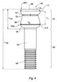
最初に、バイトが概して1と示され、インサートシート20、工具ホルダ10の上に取り付けられた切削インサート30、締結部材50、固着部材70、及びネジ90を有する支持プレート80で形成された工具ホルダ10を含んで示される図1が注目される。
First, the bite is generally designated as 1, a tool holder formed of an insert sheet 20, a cutting
工具ホルダは本体12を含み、シート20は、切削インサート30を収容するために構成された空間であり、空間は、ベース面22と、ベース面22に対して及び互いに対して曲げられた2つの側壁24a、24bとの間に規定される。さらに、工具ホルダ10は、ベース面22に開放端部を有するシートボア25と、固着部材70をその中に収容するために構成される、シートボア25に対して横向きの固着チャネル29と、を含む。
The tool holder includes the
組立て中、固着部材70は回転式でその中に収容される固着チャネル29の中に挿入され、その後、固着部材70の対応する固着ボア74がインサートボア25と位置合わせされるように回転で位置合わせされる。この位置で、締結部材50は、シートボア25の中に挿入されることができ、これにより、締結部材50のネジ山を持った先端は対応する固着ボア74の中にねじ込まれる。
During assembly, the anchoring
上記の位置では、締結部材50は、締結部材50のステムの直径よりも大きい、シートボア25の広い寸法のためにまだわずかな旋回移動を実行することができる。
At the above positions, the
さらに組立て中、支持プレート80はインサートシート20の上に設置され、これにより支持プレート80の底面82Bはベース面22上にあり、次いで指定された開口部87を介してネジ90及びシート20の一致する補助ボア27を使用し、シートに固定される。この位置で、締結部材50のヘッドは支持プレート80から突出する。
Further during assembly, the
その後、切削インサート30は、締結部材50のヘッド部分の上で支持プレート80の上に設置されることができ、支持プレート80から取り除かれることができ、工具ホルダ10から締結部材50を取り除くことなく切削インサート30の取り付け及び取り外しを可能にする。
The cutting
ここで、締結部材50の2つの異なる位置によって反映される、切削インサート30の2つの異なる状態が示される、図2A〜図2Cが注目される。
It is noted here that FIGS. 2A-2C show two different states of the cutting
特に、図2Aに示されるように、切削インサート30は、締結部材50のヘッド部分51の上で(その固定位置にあるように)その適切な位置に置かれ、これによりインサート30の底面32Bは支持プレート80の上面82Tと結合される。この位置で、締結部材50はまだ締結されておらず、従って切削インサート30はその最終位置にあるが、まだ固定されておらず、締結部材50のヘッド部分51は切削インサート30のインサートボア35に接触していない。
In particular, as shown in FIG. 2A, the cutting
図2Bに示されるように、締結部材50は(固着部材70との係合のために)それをシートボア25の中に深く通すことによって締結され、それにより締結部材50のヘッド部分はインサートボア35の内面と係合する。具体的には、締結部材50の第1締結部分57はインサートボア35の第1締結面47と接触し、締結部材50の第2締結部分55はインサートボア35の第1締結面45と接触する。
As shown in FIG. 2B, the
締結部分55、57の設計は、締結部分55、57の間にネック53が形成され、切削インサート30の内面の部分49が中に突出する空間を形成するものである。これは、後により詳細に説明されるように、締結部材に固定中にその向きを変更するのに十分な空間を与える。
The design of the
図2Bに示される固定位置で、第1締結面47との係合が、第2締結面45との係合よりもベース面22上のより大きい高所で、及び切削インサート30の切れ刃C.E.のより近くに起こることが観察される(図7Cを参照すること)。
At the fixed position shown in FIG. 2B, the engagement with the
締結部材50及び切削インサート30が別々に示される図4〜図5Bに追加の参照が行われる。
Additional references are made to FIGS. 4-5B where the
締結部材50はヘッド部分51及びシャンク部分52を含む。ヘッド部分は、第1締結部分FP1及び第1締結部分FP1とシャンク部分52との間に配置される第2締結部分FP2で形成される。締結部分FP1、FP2のそれぞれはそれぞれ対応する締結面57及び55を含む。さらに、第1締結部分FP1は、ねじ回し等の締結工具の導入のためにポート58も具備される。
The
シャンク部分は、ネジ山を持たないセグメント54及びネジ山を持ったセグメント56を有し、これによりネジ山を持たないセグメント54は、ネジ山を持ったセグメント56と第2締結部分FP2との間に挟まれる。
The shank portion has a
切削インサート30を参照すると、切削インサート30は、上面32Tと底面32Bとの間で延在する本体32を有し、4つの側面32Sが上面32Tと底面32Bの間に延在する。切削インサート30は、上面32Tと底面32Bとの間に延在する中央平面(不図示)の回りの対称設計であり、従って反対の半分はその鏡像であることを考慮して、切削インサート30の上半分だけが説明される。
Referring to the cutting
切削インサート30は、複数の表面により規定される内周を含むインサートボア35で形成される。インサートボア35は面取り部表面として上面32Tから傾斜する第1締結面47を有する。第1締結面は、切削インサートの軸の回りで半径方向に360°延在する。
The cutting
さらに、インサートボア35は、幾何学形状が錐台正方形、つまり隅が切削されている正方形と見ることができる第2締結面45a、45bの不規則な八角形の構成を具備する。これは、第2締結面45a、45b、45a等の交互のセットを生じさせる。
Further, the insert bore 35 comprises an irregular octagonal configuration of
その後、インサートボア35の内周は、やはり類似した八角形設計の中間ストリップ49を具備する。
The inner circumference of the insert bore 35 then comprises an
切削インサートの軸Xに関する第1締結面47の傾角α1が軸Xに関する第2締結面47の傾角α2よりも大きいこと、及び中間ストリップ49が軸Xに平行であることが理解される。
It is understood that the tilt angle α 1 of the
ここで図2Bに戻ると、固定位置で、締結部材50の第1締結面57は、切削インサート30の傾いた第1締結面47を押し下げ、締結部材50の第2締結面55は、切削インサート30の傾いた第2締結面45を押し下げる。これは、第1締結部分FP1により切れ刃C.E.の領域と第2締結部分FP2により切削インサート30の後部領域の両方で付加される第1下方力を提供する。
Returning to FIG. 2B, at the fixed position, the
締結部材50の締結部分FP1、FP2のそれぞれの最大直径が、インサートボア35の最も狭い部分の最大直径を超えないことに留意されたい。従って、インサートボア35の軸及び締結部材50の軸が位置合わせされるとき、切削インサート30は、締結部材50のヘッド部分51の上でインサートの上に設置されることができる、又は、インサートから取り除かれることができる。
Note that the maximum diameter of each of the fastening portions FP1 and FP2 of the
ここで、締結部材50の操作がどのようにして切削インサート30のその最終的な固定位置への移動を容易にすることができるのかを示す図2D〜図2Fが注目される。具体的には、上記例では、切削インサート30はその最終位置に設置され、単に締結部材50を締め付けることによって固定されたのに対し、本例では、部材50の締結は切削インサート50の移動も伴う。
It is noted here that FIGS. 2D-2F show how the operation of the
図2Dに示される位置で開始し、切削インサート30はその最終位置にはなく、側壁24a、24bの間の隅Cから大幅に離れている。この位置で、締結部材50は、締結部材50の軸XFMがシートボア25の軸XSBに関して角度θ1となるように固着部材70とともに傾けられる。この状態で、締結部材50の第1締結部分FP1は締結面47の上に載り、第2締結部分FP2は切削インサート30と接触していない。
Starting at the position shown in FIG. 2D, the cutting
ここで図2Eを参照すると、締結部材50がそれを固着部材70の中にねじ込むことによって締め付けられるとき、ヘッド部分51とベース面22との間の距離は減少し、FP1との係合のために、締結部材50はそのピボット軸XAの回りで右回りに傾き始め、これによりシートボア軸XSBに関する角度はここでθ2<θ1となる。同時に、これは第2締結部分FP2と第2締結面47との間で接触させ、切削インサート30の隅Cに向かう摺動を生じさせる。
Referring here to FIG. 2E, when the
締結部材50はその2つの異なる場所(それぞれ、締結面47及び45)で切削インサート30に作用し、それにより表面の傾き及びシートボアの角度から生じる以下の三重効用をもたらす。
a)FP1と面47との間の係合はXAの回りでの締結部材50の右回り回転を促し、
b)FP2と面45との間の係合はXAの回りでの締結部材50の左回り回転を促し、
c)シートボア25の角度は切削インサート30に隅に向かって移動するように促す。
The
engagement between a) FP1 and the
The engagement between the b) FP2 and the
c) The angle of the seat bore 25 prompts the cutting
(a)が、FP2が面45と接触するのを容易にし、一方(b)が、FP1が面47と接触するのを容易にすることが理解される。これは、締結部材50が常に面47と45の両方と係合していること、及び、締結部材50が切削インサート30を隅Cに向かって同時に駆動させながら、締結部材50が、切削インサート30を2つの別々の場所に固定することを確実にすることを保証する。
It is understood that (a) facilitates contact of the FP2 with the
図2Fに示されるように、最終的に、切削インサート30は、側壁24a、24bと接触し、さらに移動することができない。その後、締結部材50の締め付けは切削インサート30に対する圧力を単に増加させる。補完性効果(a)及び(b)のため、圧力が2つの異なる面47、45の間で一様に分散されることも理解されたい。言い換えると、面47に付加される圧力は右回り回転に変換され、面45に付加される圧力は左回り回転に付加されるので、切削インサート30に対する実際の下方圧力は、両方の部分FP1とFP2ともそのそれぞれの面47、45と第1係合にあるときにだけ提供することができる。
As shown in FIG. 2F, finally, the cutting
締結部材50の取り付け位置から固定位置へのその進行の間の締結部材50の上記移動は、固着部材70との係合のため、自動調整位置合わせ機構を提供する。具体的には、締結部材50は切削インサート30の動きを条件にその向きを自由にシフトし、それによって切削インサートを定位置に固定するために締結部材を切削インサート30の表面と接触させたままにする。
The movement of the
追加の例で説明されるように、自動調整機能は、異なる固着部材(回転、側面方向、軸方向)で動作可能であるが、すべては締結部材に切削インサートを適切に係合するために必要とされる自由度を与える。締結部材が(例えば、図6Aから図6Cでのように)本体に直接的にネジ付けされる場合、異なる種類の自由度も提供することができるが、こうした自由度は締結部材の弾力性及びその曲げに依存することが理解される。 As described in the additional example, the auto-adjustment feature can operate with different anchoring members (rotational, lateral, axial), but all are required to properly engage the cutting insert with the fastening member. Gives the degree of freedom to be considered. If the fastening member is screwed directly to the body (eg, as in FIGS. 6A-6C), different types of degrees of freedom can also be provided, but these degrees of freedom are the elasticity of the fastening member and It is understood that it depends on the bending.
図3A及び図3Bをさらに参照すると、角度α1(約45°)及びα2(約15°)は右回り回転を実行するように締結部材50がさらに促され、それによりインサートシート20の隅Cに向かって切削インサート30を促す締結部材50の能力を促進させるように配置される。
Further referring to FIGS. 3A and 3B , the fasteners 50 are further urged to perform clockwise rotation at angles α 1 (about 45 °) and α 2 (about 15 °), thereby cornering the insert sheet 20. Arranged to promote the ability of the
図7A〜図7Cをさらに参照すると、本願の主題の設計のいくつかの原理が明示される。
‐FP1(面57)と締結面47との間の係合のより大きい角度(45°対15°)、
‐部分FP2は、部分FP1 Atopよりも大きい量の固形物Abottomに対して圧力を付加する。これは、インサートシート20の上への切削インサート30のよりしっかりした固定を提供し、
‐FP1と切削インサート30との間の係合は、FP2と切削インサート30との間の係合よりもより高く、切れ刃C.E.により近く起こる。
Further reference to FIGS. 7A-7C illustrates some of the design principles of the subject matter of the present application.
-A larger angle of engagement between FP1 (plane 57) and fastening surface 47 (45 ° vs. 15 °),
-Partial FP2 applies pressure to a larger amount of solid A bottom than partial FP1 A top. This provides a firmer fixation of the cutting
-The engagement between the FP1 and the cutting
ここで図6A〜図6Cを参照すると、概して1’と示され、インサートシート20’、工具ホルダ10’の上に取り付けられた切削インサート30’、及び切削インサート30’を定位置に固定するために構成された締結部材50’で形成された工具ホルダ10’を含むバイトの別の例が示される。 Here, with reference to FIGS. 6A-6C, generally indicated as 1', to secure the insert sheet 20', the cutting insert 30' mounted on the tool holder 10', and the cutting insert 30'in place. Another example of a bite including a tool holder 10'formed by a fastening member 50' configured in is shown.
バイト1’の類似した要素は、(’)が追加された同じ記号表示番号でマーキングされ、これにより締結部材50’は締結部材50に同等であり、ホルダ10’はホルダ10に同等である等である。
Similar elements of bite 1'are marked with the same symbolic display number with (') added so that the fastening member 50'is equivalent to the
バイト1とバイト1’の主要な相違点は、バイト1’は固着部材を含まず、締結部材50は旋回することを許されていないという事実にある。シートボア25’は締結部材50’をしっかりと収容するように設計され、工具ホルダ10’上の切削インサート30’の最終位置に対応する角度で配向される。
The main difference between
上述の例でのように、締結部材50’の旋回移動に依存する代わりに、本設計実施形態は上述された機能(a)及び(b)を実行するために締結部材の弾力性に依存する。しかしながら、これらの機能は、回転移動により構成される代わりに、ここではそのシャンクに沿った点(不図示)の回りでの締結部材の弾性変形によって構成される。 Instead of relying on the swivel movement of the fastening member 50'as in the example above, this design embodiment depends on the elasticity of the fastening member to perform the functions (a) and (b) described above. .. However, instead of being configured by rotational movement, these functions are configured here by elastic deformation of the fastening member around a point (not shown) along its shank.
バイトホルダ1’の組立て及び操作は本来バイト1の組立て及び操作に類似している。具体的には、工具ホルダ10’は本体12’を含み、シート20’は、切削インサート30’を収容するために構成された空間であり、空間は、ベース面22’と、ベース面22’及び互いに対して曲げられた2つの側壁24a’、24b’との間に規定される。さらに、工具ホルダ10’は、ベース面22’に開放端部を有するシートボア25’を含む。
The assembly and operation of the tool holder 1'is essentially similar to the assembly and operation of the
組立て中、締結部材50’はシートボア25’の中に挿入され、これにより締結部材50’のネジ山を持った先端はシートボア25’の対応する固着部分の中にねじ込まれる。 During assembly, the fastening member 50'is inserted into the seat bore 25', whereby the threaded tip of the fastening member 50'is screwed into the corresponding anchoring portion of the seat bore 25'.
その後、切削インサート30’は、締結部材50’のヘッド部分の上で、インサートシート20’の上に設置されることができ、工具ホルダ10’から締結部材50’を取り除くことなく切削インサート30’の取り付け及び取り外しを可能にする。 After that, the cutting insert 30'can be installed on the insert sheet 20'on the head portion of the fastening member 50', without removing the fastening member 50' from the tool holder 10'. Allows installation and removal.
図4に戻ると、締結部材50は、FP1の最大直径D1及びFP2の第2最大直径D2を有し、締結部材50の総長はLFMであることが観察される。直径はそれぞれ基準面I及びIIに沿って取られる。
Returning to FIG. 4, the
構成は、D1とD2との間の距離L1がLFMの50%を超えないものである。さらにヘッド部分LHPの総長はLFMの50%を超えない。 Arrangement is one in which the distance L1 between the D1 and D2 does not exceed 50% of the L FM. Furthermore, the total length of the head portion L HP does not exceed 50% of the L FM.
さらに、D1とD2との間の距離はD1及びD2の値と相互に関連付けられ、これによって距離L1は少なくとも直径D1よりも小さい。 Further, the distance between D1 and D2 is correlated with the values of D1 and D2, whereby the distance L1 is at least smaller than the diameter D1.
締結部材50のこの設計は、締結部材50がバイト1(バイト1’の組立て中の切削インサート30’)の組立て中に切削インサート30と適切に係合することができるようにし、これによりヘッド部分が同じインサートボアの中の2つの場所と係合することが理解される。これは、締結部材が、一方の拡大部が切削インサートと係合し、他方が工具ホルダと係合するように、十分に間隔をあけて置かれるように設計される2つ以上の拡大部で形成される既知の例と逆である。
This design of the
ここで、概して101と示され、ホルダ110、切削インサート130、サポート180、締結部材150、及び固着機構170を含むバイトの別の例が示される図8A及び図8Bが注目される。図1〜図7Bに示されるバイトの要素に類似する要素は、100増加されるだけの同じ参照番号で示され、例えば、本例の締結部材150及び上述の例の締結部材50は互いの変形等である。
Of note are FIGS. 8A and 8B, generally referred to as 101, showing another example of a bite including a
本例では、締結部材150は、切削インサート130の対応する内面145及び147と係合するために構成された第1締結部分157及び第2締結部分155も含む。
In this example, the
しかしながら、上述された例とは逆に、締結部材150は、切れ刃C.E.のより近い側だけで、つまり面147を介して切削インサートに下方圧力を付加する。切削インサート130のボア35の内面40の反対の部分に、第2締結部分155は、面145の向きのために横向きの圧力を付加する。
However, contrary to the above-mentioned example, the
他のすべての態様では、バイト101のクランプ機構の操作は、バイト1に関する上記の例に説明される操作に類似している。
In all other embodiments, the operation of the clamping mechanism of the
ここで図9A〜図10を参照すると、概して101’と示され、ホルダ110’、切削インサート130’、サポート180’、締結部材150’、及び固着機構170’を含むバイトの別の例が示される。図8A〜図8Bに示されるバイトの要素に類似した要素は、(’)が追加されただけの同じ参照番号によって示され、例えば、本例の締結部材150’及び上記の例の締結部材150’は互いの変形等である。
Here, with reference to FIGS. 9A-10, generally shown as 101', another example of a bite including a holder 110', a cutting insert 130', a support 180', a fastening member 150', and a fastening mechanism 170' is shown. Is done. Elements similar to the bite elements shown in FIGS. 8A-8B are indicated by the same reference number with the addition of ('), eg, the fastening member 150'of this example and the
しかしながら、図8A及び図8Bの上述された例とは逆に、切削インサート130’の特有の設計のため、締結部材150’の第1締結部分157’は面147’に沿って1つの接点CP2と接触する。一方、第2締結部分155’は、締結面145’に沿って2つの異なる点CP1と接触する。 However, contrary to the above-mentioned examples of FIGS. 8A and 8B, due to the unique design of the cutting insert 130', the first fastening portion 157'of the fastening member 150' has one contact CP along the surface 147'. Contact with 2. On the other hand, the second fastening portion 155'contacts two different points CP 1 along the fastening surface 145'.
これは、切削インサート130’が示され、第2締結部分145’が円錐形であり、切削インサート130の上記の例に関して説明されるように円筒形ではない図10により明確に示される。
This is clearly shown by FIG. 10 where the cutting insert 130'is shown and the second fastening portion 145'is conical and not cylindrical as described for the above example of the cutting
本構成は、締結部材150’が2つの点(CP1)で圧力を付加し、それによってこれらの点のそれぞれで力Fをインサートシート120’のそれぞれの側壁に向かって付加するので、インサートシート120’の切削インサート130’のより安全且つ堅牢なクランプを提供する。 In this configuration, the fastening member 150'applies pressure at two points (CP 1 ), thereby applying force F towards each side wall of the insert sheet 120' at each of these points, thus the insert sheet. It provides a safer and more robust clamp for the 120'cutting insert 130'.
ここで、バイト101’が示されるが、切削インサート130’、が異なる切削インサート130”で置き換えられている図11A及び図11Bが注目される。従って、切削インサート130”が(”)が追加されてマーキングされるのに対して、図9A〜図10に示される要素に同一のすべての要素は同じ参照番号を維持する。 Note here are FIGS. 11A and 11B in which the bite 101'is shown, but the cutting insert 130'is replaced by a different cutting insert 130'. Therefore, the cutting insert 130' is added with ("). All elements identical to the elements shown in FIGS. 9A-10 maintain the same reference number, whereas they are marked with.
切削インサート130”は、中心ボア135”、第1締結面147a”、147b”、第2締結面145”、面取り部表面143”、及び中心内面149”を含む。
The cutting
内面147a”のそれぞれがトラフT及び2つの隆起部分148”を有するために曲線状であるのに対して、内面147b”のそれぞれが円形表面の部分であることに留意されたい。
Note that each of the
上記構成では、締結されるとき、締結部材150’の第2締結部分155’は、図9Aから図10に関して上述されたように、2つの接点CP1と接触するが、さらに、第1締結部分157’も内面147a”の湾曲のために、ここで2つの異なる接点CP2と接触する。
In the above configuration, when fastened, the second fastening portion 155'of the fastening member 150'contacts the two contact points CP 1 as described above with respect to FIGS. 9A to 10, but further, the first fastening portion. 157 'also for the curvature of the
これは、上述された例と比較して、切削インサート130”の内面140”に沿った4つの異なる点に沿って起こる切削インサート130”のより堅牢なクランプを提供する。さらに、部分147a”のそれぞれの湾曲は、締結部材150’は隆起部分148”の間のトラフTにあるように促され、それによってより正確且つより安全なクランプにつながるので、締結部材150’の熱部分の自動調整を可能にする。
This provides a more robust clamp of the cutting
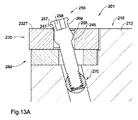
ここで、概して201と示され、ホルダ210、切削インサート230、サポート280、締結部材250、及び固着機構270を含むバイトの別の例が示される図13A及び図13Bが注目される。上述の図に示されるバイトの要素に類似した要素は、200増加されるだけの同じ参照番号で示され、例えば、本例の締結部材250及び上述の例の締結部材50、150は互いの変形等である。
Of note are FIGS. 13A and 13B, generally designated as 201, showing another example of a bite including a
本例では、標準的な切削インサート230が使用され、締結部材は第1締結部分257及び第2締結部分255を含む。第1締結部分257は曲線状であり、締結部分250が切削インサート230の内面240の部分だけではなく、切削インサートの頂面232Tでも締め付けることを可能にし、それによってインサートシート220の側壁から遠いボア235の場所で切削インサートの締付けを提供する。用語『遠い』は、切削インサート230の内面に関して理解されるべきである。つまり、内面は側壁のより近い部分及び側壁からより遠い(遠い)部分を有する。第2締結面255で、締結部材250は側壁に向かって切削インサート230の横向きのクランプを実行する。
In this example, a
ここで図14A及び図14Bを参照すると、概して201’と示され、ホルダ210’、切削インサート230’、サポート280’、締結部材250’、及び固着機構270’を含むバイトの別の例が示される。上述の図に示されるバイトの要素に類似する要素は、(’)が追加されただけの同じ参照番号により示され、例えば、本例の締結部材250’及び上述の例の締結部材50、150、250’は互いの変形等である。
Here, with reference to FIGS. 14A and 14B, generally referred to as 201', another example of a bite including a holder 210', a cutting insert 230', a support 280', a fastening member 250', and a fastening mechanism 270' is shown. Is done. Elements similar to the elements of the bite shown in the above figure are indicated by the same reference number with the addition of ('), eg, the fastening member 250'of this example and the
本例では、上述の例と逆に、締結部材250’だけが単一の接触面247’を介して、切削インサート230’の内面の遠い側、つまり切れ刃C.E.のより近い内面のその部分で、その第1締結部分257’を介して切削インサート230’と接触する。
In this example, contrary to the above example, only the fastening member 250'is located on the far side of the inner surface of the cutting insert 230' via a
さらに、図14Cに示されるように、切削インサート247’の第1締結面は、上向きの角度αで形成され、これにより締結部材250’のヘッド部分と係合して、それは第1締結面247’から離れて横向きに滑るのを妨げられる。具体的には、角度αは、ヘッド部分の周辺領域から延長されたRL線に関して、締結部材250’(図14Cの直角を参照)の中心軸Xに垂直に、Bで示される切削インサート230’の第1締結面247’の部分がこうした滑りを遮るために並置されるように選ばれる。
Further, as shown in FIG. 14C, the first fastening surface of the cutting insert 247'is formed at an upward angle α, thereby engaging with the head portion of the fastening member 250', which is the
ここで、バイト101が示されるが、切削インサート130が、異なる切削インサート130’”で置き換えられている図15A及び図15Bが注目される。従って、切削インサート130’”が追加された(’”)でマーキングされるのに対して、図8A及び図8Bに示される要素に同一のすべての要素は同じ参照番号を維持する。
Note that FIG. 15A and FIG. 15B, where the
切削インサート130’”は、中心ボア135’”、第1締結面147a’”、147b’”、第2締結面145’”、面取り部表面143’”、及び中心内面149’”を含む。内面147a’”のそれぞれがトラフT及び2つの隆起部分148’”を有するために曲線状であるのに対して、内面147b’”のそれぞれは円形の表面の部分であることに留意されたい。
The cutting insert 130'" includes a central bore 135'", a
上記構成では、締結されるとき、締結部材150の第2締結部分155は、図8A及び図8Bに関して上述されたように、2つの接点CP1と接触するが、さらに第1締結部分157もここで内面147a’”の湾曲のために2つの異なる点CP2と接触する。
In the above configuration, when fastened, the
この本質では、切削インサート130’”は、バイトホルダ110にだけ適切な、上述されたインサート130”に類似している。
In this essence, the cutting insert 130'" is similar to the insert 130' described above, which is only suitable for the
ここで図17A〜図18を参照すると、概して401と示され、その切削インサート430の半径方向の構成を有するフライス削り工具が示される。フライス削り工具401は、ホルダ410、複数の切削インサート430、サポート480、締結部材450、及び固着機構470を含む。上記図に示されるバイトの要素に類似した要素は、400増加されただけの同じ参照番号で示され、例えば、本例の締結部材450、及び上述の例の締結部材50、150、150’、250、250’は互いの変形等である。
Here, with reference to FIGS. 17A-18, a milling tool is generally shown as 401 and has a radial configuration of its
本例では、締結部材450及びクランプ機構は全体として、上述の例に関して説明されたものに類似している。つまり、締結部材450は2つの締結部分455、457を有し、切削インサート430の内面の2つのそれぞれの面445、447と接触するために構成される。
In this example, the
さらに図17Cに示される本例の構成では、締結部材450によって切削インサート430に付加される力は切削インサート430の対角線に沿って、つまり切削隅を横切って向けられないが、むしろオフセットで向けられる。具体的には、力は対角線L1に関して角度θで偏位させられる線L2に沿って付加される。
Further, in the configuration of this example shown in FIG. 17C, the force applied to the cutting
この構成は、それがフライス削り工具401の回転中及びワークピースとの接触中にフライス削り工具401に付加される力を考慮に入れるので、(回転操作について上述された工具と対照的に)フライス削り操作の間の切削インサートのより安全なクランプを容易にする。
This configuration takes into account the force applied to the
ここで図19A〜図20Bを参照すると、概して401’と示され、その切削インサート430’の接線方向の構成を有する、フライス削り工具の別の例が示される。フライス削り工具401’は、ホルダ410’、複数の切削インサート430’、サポート480’、締結部材450’、及び固着機構470’を含む。上述の図に示されるバイトの要素に類似した要素は、(’)が追加された同じ参照番号で示され、例えば本例の締結部材450’及び上述の例の締結部材50、150、150’、250、250’、450は互いの変形等である。
Here, with reference to FIGS. 19A-20B, another example of a milling tool, generally designated as 401'and having a tangential configuration of its cutting insert 430', is shown. The milling tool 401'includes a holder 410', a plurality of cutting inserts 430', a support 480', a fastening member 450', and a fastening mechanism 470'. Elements similar to the elements of the bite shown in the figure above are indicated by the same reference number with the addition of ('), eg, fastening members 450'of this example and
本例では、切削インサート430’のクランプは概してバイト150に関して説明されたクランプに類似し、インサート430’は中心ボア435’、第1締結面447a’、第2締結面445’、面取り部表面443’、及び中心内面449’を有する。
In this example, the clamp of the cutting insert 430'is generally similar to the clamp described for the
内面447a’のそれぞれが頂点P及び2つの下げられた部分448’を有するために曲線状であるのに対して、内面447b’のそれぞれは円形表面の部分であることに留意されたい。面447b’は2つの隣接する面447a’の間に挟まれ、切削隅C.E.の2等分線上にある。従って、切削インサート430’が固定されるとき、締結部材は2等分線の左に対して第1接点、及び2等分線の右に第2接点を有し、締結部材に対する荷重のよりバランスの取れた適用に貢献する(上述の図16Aも参照すること)。
Note that each of the inner surfaces 447b'is a portion of the circular surface, whereas each of the
この構成は、第1締結部分457’との2つの接点で、締結部材450’が切削インサート430’と接触するのを可能にする。切削インサート130’、130”等の上記例と逆に、本例では、部分447a’は凹状でトラフTを有する代わりに、凸状であり、頂点Pを有する。 This configuration allows the fastening member 450'to come into contact with the cutting insert 430' at two contacts with the first fastening portion 457'. Contrary to the above example of cutting inserts 130', 130', etc., in this example, the portion 447a'is convex and has a vertex P instead of being concave and having a trough T.
すべての他の態様で、切削インサート430’及びクランプ機構は上述された方法と同様の方法で動作する。 In all other embodiments, the cutting insert 430'and the clamping mechanism operate in a manner similar to that described above.
ここで、概して501と示され、ホルダ510、複数の切削インサート530、サポート580、締結部材550、及び固着機構570を含むバイトが示される、図21が注目される。
Of note here is FIG. 21, which is generally designated as 501 and shows a bite including a
上述された例と逆に、固着部材570は回転のためではなく、むしろ切削工具ホルダ510の二次ボア529に沿った直線変位に対して構成される。さらに、この変位は、固着部材570とボア529の閉じられた端部との間に挟まれるばね590によってばね偏倚される。
Contrary to the example described above, the anchoring
動作中、締結部材550がねじ込まれるとき、締結部材550は、ベース面522に向かって固着部材570を引こうと試みる。しかしながら、固着部材570はボア529に常駐するので、こうした移動は妨げられる。
During operation, when the
それにも関わらず、固着部材570の中心軸と締結部材550の中心軸との間の角度γ、90°とは異なる角度のために、ネジ切りはばね590のバイアス力に対して、矢印Sの方向でボア529の閉じられた端部に向かう固着部材570の摺動を生じさせる。
Nevertheless, due to the angle γ between the central axis of the anchoring
締結部材550のネジを外すとき、固着部材570はばね590のバイアス力を受けてその元の位置に摺動して戻る。
When unscrewing the
ここで図22を参照すると、概して601と示され、ホルダ610、複数の切削インサート630、サポート680、締結部材650、及び固着機構670を含む、バイトの別の例が示される。
Here, with reference to FIG. 22, generally referred to as 601 and another example of a bite including a
バイト601はバイト501に類似し、相違点は、固着部材670が反対角度δで配向され、締結部材650も締結部材550の角度に反対の角度で配向される点である。
The
この構成では、上述の構成と同様に、締結部材650はねじ込まれるとき、締結部材650は固着部材670をベース表面622に向かって引っ張ろうと試みる。しかしながら、締結部材670はボア629に常駐するので、こうした移動は妨げられる。
In this configuration, similar to the above configuration, when the
それにも関わらず、固着部材670の中心軸と締結部材650の中心軸の間の角度δ、90°とは異なる角度のため、ネジ切りはばね690のバイアス力に対して、矢印Sの方向でボア629の閉じられた端部に向かう固着部材670の摺動を生じさせる。
Nevertheless, since the angle between the central axis of the fixing member 670 and the central axis of the
締結部材550のネジを外すとき、固着部材570はばね590のバイアス力を受けてその元の位置に摺動して戻る。
When unscrewing the
最後に、図23Aから図23Cを参照すると、概して701と示され、ホルダ710、複数の切削インサート730、サポート780、締結部材750、及び固着機構770を含む、バイトの別の例が示される。
Finally, referring to FIGS. 23A to 23C, reference to FIG. 23C, generally referred to as 701, shows another example of a bite, including a
バイト701はバイト601に類似し、相違点は、締結部材がそのクランプ部分の丸みを帯びた端縁を有する点である。
The
本発明が関係する当業者は、多数の変更、変形、及び修正を、必要な変更を加えて、本発明の範囲から逸脱することなく行うことができることを容易に理解する。 Those skilled in the art relating to the present invention will readily appreciate that numerous changes, modifications and modifications can be made without departing from the scope of the invention with the necessary changes.
Claims (14)
前記上面から傾斜して前記インサート軸の回りで半径方向に延在する第1クランプ面と、
前記第1クランプ面から前記底面に向かって軸方向に離間された第2クランプ面と、を備え、
前記切削工具ホルダが本体及び締結部材を備え、前記本体が、
側壁とベース面との間に規定されたインサートシートであって、その中に前記切削インサートを受け入れるために構成されるインサートシートと、
シートボア軸に沿って延在し、前記ベース面に開口端部を有するシートボアと、を備え、
前記締結部材が、締結部材軸を規定し、前記シートボアの中に受け入れられるために構成された近位のシャンク部分及び前記締結部材軸に沿って延在する遠位のヘッド部分を備え、前記締結部材は、前記締結部材が前記切削インサートの前記インサートシートの中への位置決めを可能にしつつ前記シートボアと係合したままである取り付け位置と、前記締結部材が前記切削インサートを前記インサートシートの中に固定する固定位置と、の間で移動することができ、前記ヘッド部分が、
前記固定位置で前記切削インサートの前記第1クランプ面を圧迫するために、前記締結部材軸に向かって近位に先細る第1締結面を有する第1締結部分と、
前記第1締結部分から軸方向に離間され、前記シャンク部分と前記第1締結部分との間に配置された第2締結部分であって、前記固定位置で前記切削インサートの前記第2クランプ面を圧迫するための第2締結面を有する第2締結部分と、
前記第1締結部分と前記第2締結部分との間に形成され、前記第1締結部分及び前記第2締結部分のそれぞれの直径未満の直径を有するネック部分と、を備え、
前記締結部材が前記固定位置にあるとき、前記締結部材軸が前記シートボア軸に位置合わせされ、かつ、前記第1締結面と前記インサート軸との間、及び、前記第1クランプ面と前記インサート軸との間に第1係合角度がそれぞれ規定され、前記第2締結面と前記インサート軸との間、及び、前記第2クランプ面と前記インサート軸との間に第2係合角度がそれぞれ規定され、前記第1係合角度は前記第2係合角度より大きい、切削工具。 A cutting tool comprising a cutting tool holder and a cutting insert mounted on the cutting tool holder, wherein the cutting insert defines an insert axis and has a top surface, a bottom surface, and a top surface and a bottom surface. The cutting insert comprises at least one side surface extending in between and an insert bore extending between the top surface and the bottom surface.
A first clamp surface that is inclined from the upper surface and extends radially around the insert shaft.
A second clamp surface, which is axially separated from the first clamp surface toward the bottom surface, is provided.
The cutting tool holder includes a main body and a fastening member, and the main body is
An insert sheet defined between the side wall and the base surface, wherein the insert sheet is configured to receive the cutting insert.
A seat bore extending along the seat bore axis and having an open end on the base surface is provided.
The fastening member comprises a proximal shank portion configured to define a fastening member axis and be received in the seat bore and a distal head portion extending along the fastening member axis. The member has a mounting position in which the fastening member remains engaged with the seat bore while allowing the cutting insert to be positioned into the insert sheet, and the fastening member places the cutting insert into the insert sheet. It can be moved between a fixed position to be fixed, and the head portion is
A first fastening portion having a first fastening surface that tapers proximally towards the fastening member axis in order to compress the first clamp surface of the cutting insert at the fixed position.
A second fastening portion that is axially separated from the first fastening portion and is arranged between the shank portion and the first fastening portion, and the second clamp surface of the cutting insert is held at the fixed position. A second fastening portion with a second fastening surface for compression,
A neck portion formed between the first fastening portion and the second fastening portion and having a diameter smaller than the diameter of each of the first fastening portion and the second fastening portion is provided.
When the fastening member is in the fixed position, the fastening member shaft is aligned with the seat bore shaft, and between the first fastening surface and the insert shaft, and between the first clamp surface and the insert shaft. is defined first engagement angle, respectively, the second between the engagement surface and the insert shaft, and, second engagement angle between the insert shaft and the second clamping surface, respectively defined between the It is, the first engagement angle and the second engagement angle greater than the cutting tool.
前記固着軸の回りの回転、
前記固着軸に沿った軸方向移動、又は、
前記固着軸に対して横向きの方向での側面方向移動、のうちの1以上のために構成される、請求項1〜6のいずれか1項に記載の切削工具。 Further comprising a anchoring element that is received in the anchoring channel of the body of the cutting tool holder and configured to engage the fastening member, the anchoring element is oriented transversely to the seat bore axis. The fixing axis is defined, and the fixing element is
Rotation around the fixation axis,
Axial movement along the fixing axis, or
The cutting tool according to any one of claims 1 to 6, configured for one or more of lateral movements in a lateral direction with respect to the fixation axis.
ベース面を有するインサートシートであって、その中に前記切削インサートを受け入れるために構成されるインサートシートと、
シートボア軸に沿って延在し、前記ベース面に開口端部を有するシートボアと、を備え、
前記締結部材が、締結部材軸を規定し、前記シートボアの中に受け入れられるために構成された近位のシャンク部分及び前記締結部材軸に沿って延在する遠位のヘッド部分を備え、前記締結部材は、前記締結部材が前記切削インサートの前記インサートシートの中への位置決めを可能にしつつ前記シートボアと係合したままである取り付け位置と、前記締結部材が前記切削インサートを前記インサートシートの中に固定する固定位置と、の間で移動することができ、前記ヘッド部分が、
前記固定位置で前記切削インサートを圧迫するために、前記締結部材軸に向かって近位に先細る第1締結面を有する第1締結部分と、
前記第1締結部分から軸方向に離間され、前記シャンク部分と前記第1締結部分との間に配置された第2締結部分であって、前記固定位置で前記切削インサートを圧迫するための第2締結面を有する第2締結部分と、
前記第1締結部分と前記第2締結部分との間に形成され、前記第1締結部分及び前記第2締結部分のそれぞれの直径未満の直径を有するネック部分と、を備え、
前記切削インサートが、インサート軸を規定し、かつ、上面、底面、前記上面と前記底面との間に延在する少なくとも1つの側面、及び前記上面と前記底面との間に延在するインサートボアを備え、前記切削インサートは、
前記上面から傾斜して前記インサート軸の回りで半径方向に延在する第1クランプ面と、
前記第1クランプ面から前記底面に向かって軸方向に離間された第2クランプ面と、を備え、
前記切削インサートが前記固定位置の前記締結部材によって前記インサートシートの中に固定されるとき、前記第1締結面と前記インサート軸との間、及び、前記第1クランプ面と前記インサート軸との間に第1係合角度がそれぞれ規定され、前記第2締結面と前記インサート軸との間、及び、前記第2クランプ面と前記インサート軸との間に第2係合角度がそれぞれ規定され、前記第1係合角度は前記第2係合角度より大きい、切削インサート。 A cutting insert that is mounted on a cutting tool holder to form a cutting tool, wherein the cutting tool holder includes a main body and a fastening member, and the main body is
An insert sheet having a base surface, wherein the insert sheet is configured to receive the cutting insert.
A seat bore extending along the seat bore axis and having an open end on the base surface is provided.
The fastening member comprises a proximal shank portion configured to define a fastening member axis and be received in the seat bore and a distal head portion extending along the fastening member axis. The member has a mounting position in which the fastening member remains engaged with the seat bore while allowing the cutting insert to be positioned into the insert sheet, and the fastening member places the cutting insert into the insert sheet. It can be moved between a fixed position to be fixed, and the head portion is
A first fastening portion having a first fastening surface that tapers proximally towards the fastening member axis to compress the cutting insert at the fixed position.
A second fastening portion that is axially separated from the first fastening portion and is arranged between the shank portion and the first fastening portion, for pressing the cutting insert at the fixed position. A second fastening part with a fastening surface and
A neck portion formed between the first fastening portion and the second fastening portion and having a diameter smaller than the diameter of each of the first fastening portion and the second fastening portion is provided.
The cutting insert defines an insert shaft and includes a top surface, a bottom surface, at least one side surface extending between the top surface and the bottom surface, and an insert bore extending between the top surface and the bottom surface. The cutting insert is
A first clamp surface that is inclined from the upper surface and extends radially around the insert shaft.
A second clamp surface, which is axially separated from the first clamp surface toward the bottom surface, is provided.
When the cutting insert is fixed into the insert sheet by the fastening member at the fixed position, between the first fastening surface and the insert shaft, and between the first clamping surface and the insert shaft. first engagement angle is defined respectively between the insert shaft and the second engagement surface, and the second engagement angle are respectively defined between the insert shaft and the second clamping surface, the the first engagement angle greater than the second engagement angle, the cutting insert.
前記上面から傾斜して前記インサート軸の回りで半径方向に延在する第1クランプ面と、
前記第1クランプ面から前記底面に向かって軸方向に離間された第2クランプ面と、を備え、
前記切削工具ホルダが本体及び締結部材を備え、前記本体が、
側壁とベース面との間に規定されたインサートシートであって、その中に前記切削インサートを受け入れるために構成されるインサートシートと、
シートボア軸に沿って延在し、前記ベース面に開口端部を有するシートボアと、を備え、
前記締結部材が、締結部材軸を規定し、前記シートボアの中に受け入れられるために構成された近位のシャンク部分及び前記締結部材軸に沿って延在する遠位のヘッド部分を備え、前記締結部材は、前記締結部材が前記切削インサートの前記インサートシートの中への位置決めを可能にしつつ前記シートボアと係合したままである取り付け位置と、前記締結部材が前記切削インサートを前記インサートシートの中に固定する固定位置と、の間で移動することができ、前記ヘッド部分が、
前記固定位置で前記切削インサートの前記第1クランプ面を圧迫するために、前記締結部材軸に向かって近位に先細る第1締結面を有する第1締結部分と、
前記第1締結部分から軸方向に離間され、前記シャンク部分と前記第1締結部分との間に配置された第2締結部分であって、前記固定位置で前記切削インサートの前記第2クランプ面を圧迫するための第2締結面を有する第2締結部分と、
前記第1締結部分と前記第2締結部分との間に形成され、前記第1締結部分及び前記第2締結部分のそれぞれの直径未満の直径を有するネック部分と、を備え、
前記締結部材が前記固定位置にあるとき、前記締結部材軸が前記シートボア軸に位置合わせされ、かつ、前記第1締結面と前記インサート軸との間、及び、前記第1クランプ面と前記インサート軸との間に第1係合角度がそれぞれ規定され、前記第2締結面と前記インサート軸との間、及び、前記第2クランプ面と前記インサート軸との間に第2係合角度がそれぞれ規定され、前記第1係合角度は前記第2係合角度より大きい、切削工具ホルダ。 A cutting tool holder on which a cutting insert is attached to form a cutting tool, wherein the cutting insert defines an insert shaft and extends at least on the top surface, bottom surface, between the top surface and the bottom surface. The cutting insert comprises one side surface and an insert bore extending between the top surface and the bottom surface.
A first clamp surface that is inclined from the upper surface and extends radially around the insert shaft.
A second clamp surface, which is axially separated from the first clamp surface toward the bottom surface, is provided.
The cutting tool holder includes a main body and a fastening member, and the main body is
An insert sheet defined between the side wall and the base surface, wherein the insert sheet is configured to receive the cutting insert.
A seat bore extending along the seat bore axis and having an open end on the base surface is provided.
The fastening member comprises a proximal shank portion configured to define a fastening member axis and be received in the seat bore and a distal head portion extending along the fastening member axis. The member has a mounting position in which the fastening member remains engaged with the seat bore while allowing the cutting insert to be positioned into the insert sheet, and the fastening member places the cutting insert into the insert sheet. It can be moved between a fixed position to be fixed, and the head portion is
A first fastening portion having a first fastening surface that tapers proximally towards the fastening member axis in order to compress the first clamp surface of the cutting insert at the fixed position.
A second fastening portion that is axially separated from the first fastening portion and is arranged between the shank portion and the first fastening portion, and the second clamp surface of the cutting insert is held at the fixed position. A second fastening portion with a second fastening surface for compression,
A neck portion formed between the first fastening portion and the second fastening portion and having a diameter smaller than the diameter of each of the first fastening portion and the second fastening portion is provided.
When the fastening member is in the fixed position, the fastening member shaft is aligned with the seat bore shaft, and between the first fastening surface and the insert shaft, and between the first clamp surface and the insert shaft. is defined first engagement angle, respectively, the second between the engagement surface and the insert shaft, and, second engagement angle between the insert shaft and the second clamping surface, respectively defined between the It is, the first engagement angle and the second engagement angle greater than the cutting tool holder.
Applications Claiming Priority (5)
| Application Number | Priority Date | Filing Date | Title |
|---|---|---|---|
| IL238546A IL238546A0 (en) | 2015-04-30 | 2015-04-30 | Dynamic clamping mechanism |
| IL238546 | 2015-04-30 | ||
| IL23905315 | 2015-05-28 | ||
| IL239053 | 2015-05-28 | ||
| PCT/IL2016/050424 WO2016174663A1 (en) | 2015-04-30 | 2016-04-21 | Dynamic clamping mechanism |
Publications (3)
| Publication Number | Publication Date |
|---|---|
| JP2018514401A JP2018514401A (en) | 2018-06-07 |
| JP2018514401A5 JP2018514401A5 (en) | 2019-05-16 |
| JP6966327B2 true JP6966327B2 (en) | 2021-11-17 |
Family
ID=55948918
Family Applications (1)
| Application Number | Title | Priority Date | Filing Date |
|---|---|---|---|
| JP2017553174A Active JP6966327B2 (en) | 2015-04-30 | 2016-04-21 | Cutting tools, cutting inserts and cutting tool holders |
Country Status (5)
| Country | Link |
|---|---|
| US (1) | US10307832B2 (en) |
| EP (1) | EP3288701A1 (en) |
| JP (1) | JP6966327B2 (en) |
| IL (1) | IL255143B (en) |
| WO (1) | WO2016174663A1 (en) |
Families Citing this family (3)
| Publication number | Priority date | Publication date | Assignee | Title |
|---|---|---|---|---|
| EP3603862B1 (en) * | 2017-03-24 | 2024-01-24 | Sumitomo Electric Hardmetal Corp. | Milling tool |
| US11148213B2 (en) * | 2019-01-03 | 2021-10-19 | Kennametal Inc. | Hardware fastener with movable threaded element and one or more spring-like members |
| CA3137799A1 (en) * | 2019-05-20 | 2020-11-26 | Iscar Ltd. | High-feed turning tool assembly |
Family Cites Families (96)
| Publication number | Priority date | Publication date | Assignee | Title |
|---|---|---|---|---|
| AT6206B (en) | 1897-03-13 | 1901-12-27 | Johannes Otto Sahlmann | |
| US3027623A (en) | 1959-06-25 | 1962-04-03 | Viking Tool Company | Clamp-type holder for throw-away and indexible cutting inserts |
| US3138846A (en) | 1961-11-13 | 1964-06-30 | Posa Cut Corp | Grooving tool |
| DE1260926B (en) | 1962-11-29 | 1968-02-08 | Karl Hertel | Knife head |
| US3341919A (en) | 1963-08-01 | 1967-09-19 | Futurmill Inc | Tool holder arrangement |
| DE1256514B (en) | 1963-08-21 | 1967-12-14 | Zapp Werkzeug & Maschf R | Cutting plate for a cutting tool, in particular a turning tool |
| US3299489A (en) | 1963-08-21 | 1967-01-24 | Espa Establishment For Securit | Tool-holder provided with reversible cutting tool, and the tool itself |
| US3341921A (en) | 1966-01-10 | 1967-09-19 | Gen Electric | Cutting insert |
| US3341923A (en) | 1966-09-09 | 1967-09-19 | Gen Electric | Cutting tool |
| US3491421A (en) | 1967-12-27 | 1970-01-27 | Madison Ind Inc | Tool holder for throw-away inserts |
| FR2040515A5 (en) | 1969-04-01 | 1971-01-22 | Electro Metallurg | |
| JPS4844661B1 (en) | 1970-05-21 | 1973-12-26 | ||
| US3747179A (en) | 1971-05-26 | 1973-07-24 | N Lovendahl | Tool holder arrangement |
| JPS5431690B1 (en) | 1971-06-01 | 1979-10-09 | ||
| BE793105A (en) | 1971-12-24 | 1973-04-16 | Walter Gmbh Montanwerke | EXCHANGEABLE CUTTING INSERT MILLING TOOL |
| US3740807A (en) | 1972-02-25 | 1973-06-26 | Metal Cutting Tools Inc | Inserted blade cutting tool with locking pin |
| US3787941A (en) | 1972-07-17 | 1974-01-29 | Warner Swasey Co | Locking pin mechanism for securing tool bits to tool holders |
| US3913197A (en) | 1973-11-19 | 1975-10-21 | Heinz K Wolf | Positive lock insert |
| US3946473A (en) | 1974-04-15 | 1976-03-30 | Ex-Cello-O Corporation | Cutting tools |
| US3925868A (en) | 1974-06-21 | 1975-12-16 | Mccrosky Tool Corp | Clamping assembly for cutter bits |
| NL7510219A (en) | 1974-09-13 | 1976-03-16 | Zapp Werkzeug & Maschf R | CUTTING TOOLS. |
| DE2443756A1 (en) | 1974-09-13 | 1976-04-01 | Zapp Werkzeug & Maschf R | Holder for interchangeable cutting bit - has screwed bit-clamping element engaging nut on inclined face |
| DE2443755A1 (en) | 1974-09-13 | 1976-04-01 | Zapp Werkzeug & Maschf R | CUTTING TOOL |
| US4035887A (en) | 1975-07-23 | 1977-07-19 | Karl Hertel | Cutting tools |
| US4044440A (en) | 1976-02-25 | 1977-08-30 | Stier Henry W | Cutting tool |
| SU703248A1 (en) | 1976-12-23 | 1979-12-15 | Сестрорецкий Инструментальный Завод Им. Воскова | Cutting tool |
| DE2703696C2 (en) | 1977-01-29 | 1990-03-29 | Fried. Krupp Gmbh, 4300 Essen | Cutting tool |
| AT350875B (en) | 1977-10-12 | 1979-06-25 | Plansee Metallwerk | TOOL HOLDERS |
| SU665993A1 (en) | 1978-01-10 | 1979-06-05 | Сестрорецкий Инструментальный Завод Им. Воскова | Cutting tool |
| DE2853313C2 (en) | 1978-12-09 | 1985-03-21 | Komet Stahlhalter- Und Werkzeugfabrik Robert Breuning Gmbh, 7122 Besigheim | Clamping device for an indexable insert |
| DE2906148A1 (en) | 1979-02-17 | 1980-08-28 | Walter Gmbh Montanwerke | CUTTING TOOL WITH REPLACEMENT INSERT |
| DE2935426A1 (en) | 1979-09-01 | 1981-03-26 | Günther 90491 Nürnberg Hertel | CUTTING TOOL, e.g. SLOT MILLING OR ROOM NEEDLE |
| SU831394A1 (en) | 1979-09-27 | 1981-05-23 | Tereshonok Ivan S | Cutting tool |
| SU848158A1 (en) | 1979-10-12 | 1981-07-23 | Научно-Производственное Объединение Помеханизации И Автоматизации Производствамашин Для Хлопководства Нпо "Технолог" | Cutting tool |
| AT366306B (en) | 1980-04-04 | 1982-04-13 | Plansee Metallwerk | CUTTING TOOL |
| US4397592A (en) | 1980-11-10 | 1983-08-09 | Kennametal Inc. | Insert holder and method of holding |
| US4398853A (en) | 1980-11-10 | 1983-08-16 | Kennametal Inc. | Insert holder and method of holding |
| DE3118467A1 (en) | 1981-05-09 | 1982-11-25 | Fried. Krupp Gmbh, 4300 Essen | "ARRANGEMENT FOR FIXING INTERCHANGEABLE CUTTING INSERT ON A TOOL HOLDER" |
| JPS57189718A (en) | 1981-05-13 | 1982-11-22 | Sumitomo Electric Ind Ltd | Rotary disk cutting tool |
| US4507023A (en) | 1981-05-30 | 1985-03-26 | Tokyo Shibaura Denki Kabushiki Kaisha | Cutting tool |
| SU1079370A1 (en) | 1982-02-22 | 1984-03-15 | Ленинградский Ордена Ленина И Ордена Красного Знамени Механический Институт | Cutting tool with mechanical fastening of polyhedral plate which is not turned down |
| DE3301191A1 (en) | 1983-01-15 | 1984-07-19 | Fried. Krupp Gmbh, 4300 Essen | Tool with at least one part to be releasably fastened |
| US4527930A (en) | 1983-03-23 | 1985-07-09 | Hugh Harroun | Ball nose end cutting tool |
| US4621957A (en) | 1983-09-20 | 1986-11-11 | The Boeing Company | Inverted cutter |
| SE445314B (en) | 1984-09-26 | 1986-06-16 | Santrade Ltd | TOOLS WITH FENDER PREFERRED FOR SWEARING |
| FR2608951B1 (en) | 1986-12-30 | 1994-05-06 | Electro Metallurgie Ste Indle | DEVICE FOR DEMOUNTABLE FIXING OF A CUTTING INSERT ON A TOOL HOLDER |
| SE463703B (en) | 1987-04-15 | 1991-01-14 | Seco Tools Ab | Cutting tool |
| BR8800380A (en) | 1987-07-24 | 1989-02-08 | Gte Valenite Corp | CUTTING TOOL |
| JPH0753062B2 (en) | 1987-11-19 | 1995-06-07 | セイレイ工業株式会社 | Pruner controller |
| JP2559437Y2 (en) | 1989-06-12 | 1998-01-19 | 三菱マテリアル株式会社 | Slow way tip clamping mechanism |
| JPH03281115A (en) | 1990-03-30 | 1991-12-11 | Mitsubishi Materials Corp | Throw-away type cutting tool |
| SE9003705L (en) | 1990-11-21 | 1992-05-22 | Seco Tools Ab | SKAERVERKTYG |
| US5167473A (en) | 1991-06-24 | 1992-12-01 | Allied-Signal Inc. | Unidirectional insert lock |
| CA2062213C (en) | 1992-03-03 | 1996-07-16 | Alfonso Minicozzi | Indexable cutting insert for rotary cutting tools |
| SE505726C2 (en) | 1995-02-27 | 1997-10-06 | Sandvik Ab | Clamping device for cutting plates |
| IL112818A (en) | 1995-02-28 | 1999-10-28 | Iscar Ltd | Tool holder having a grooved seat |
| JPH09108909A (en) | 1995-10-18 | 1997-04-28 | Mitsubishi Materials Corp | Throw away tip and its clamp mechanism |
| IL117015A (en) | 1996-02-02 | 1998-12-27 | Iscar Ltd | Cutting tool |
| JP3351955B2 (en) | 1996-02-29 | 2002-12-03 | 日本特殊陶業株式会社 | Tool unit |
| SE509324C2 (en) | 1996-04-19 | 1999-01-11 | Seco Tools Ab | Tools for cutting machining |
| SE510851C2 (en) | 1996-12-23 | 1999-06-28 | Sandvik Ab | Cuts and holders for cutting metalworking |
| US5913644A (en) | 1998-04-20 | 1999-06-22 | Kennametal Inc. | Helical mill having multiple flutes with differing rake angles |
| IL124282A (en) | 1998-04-29 | 2001-10-31 | Iscar Ltd | Cutting tool assembly and a cutting insert for use therein |
| US6579042B1 (en) | 2000-10-11 | 2003-06-17 | Sandvik Inc. | Cutter body with cutting inserts and methods for assembling same |
| IL144154A0 (en) | 2001-07-05 | 2002-05-23 | Iscar Ltd | Cutting tool and cutting insert therefor |
| IL144855A0 (en) | 2001-08-12 | 2002-06-30 | Iscar Ltd | Cutting tool |
| DE10144449A1 (en) | 2001-09-10 | 2005-03-24 | Gustav Werthwein | Cutting insert for tools for machining workpieces and tools for the use of this insert |
| US6811359B2 (en) | 2002-05-31 | 2004-11-02 | Kennametal Inc. | True helical cutter system |
| US7144205B2 (en) | 2003-05-09 | 2006-12-05 | Kennametal Inc. | Insert retention screw and tool body and insert therewith |
| SE526536C2 (en) | 2003-11-19 | 2005-10-04 | Sandvik Intellectual Property | Tool head with clamping device in the form of a nut roller acting in a slot |
| SE526586C2 (en) | 2003-11-25 | 2005-10-11 | Sandvik Intellectual Property | Chip separating machining tool including a male / female connection between cutting member and holder part |
| KR100625838B1 (en) | 2004-11-16 | 2006-09-20 | 대구텍 주식회사 | Insert Tip |
| US7273331B2 (en) | 2004-12-29 | 2007-09-25 | Giannetti Enrico R | Boring bar having internal coolant supply |
| IL169491A (en) | 2005-06-30 | 2009-06-15 | Carol Smilovici | Cutting insert |
| SE529311C2 (en) | 2005-12-05 | 2007-07-03 | Seco Tools Ab | A chip separation tool where the threaded joint is arranged to allow winding of the locking screw |
| US7261495B1 (en) | 2006-02-21 | 2007-08-28 | Kennametal Inc. | Assembly for retaining a cutting insert in a pocket of a tool holder |
| JP4867661B2 (en) | 2006-03-02 | 2012-02-01 | 三菱マテリアル株式会社 | Insert detachable cutting tool |
| DE102006017074A1 (en) | 2006-04-10 | 2007-10-11 | Walter Ag | Shim for double-sided indexable inserts |
| SE530374C2 (en) | 2006-05-23 | 2008-05-20 | Pramet Tools Sro | Cutting insert and cutting tool where the clamping surface of the clamping hole is in the form of an elliptical cone |
| IL178813A (en) | 2006-10-23 | 2010-06-30 | Iscar Ltd | Tangential cutting insert having a base protrusion seating arrangement |
| SE530631C2 (en) | 2006-12-12 | 2008-07-22 | Sandvik Intellectual Property | Tools and cutters for chip separating machining |
| IL182078A (en) | 2007-03-20 | 2011-09-27 | Iscar Ltd | System for attaching a cutting member to a cutter |
| EP2514559A3 (en) | 2007-06-06 | 2013-04-17 | No Screw Ltd. | Drill head |
| WO2009028747A1 (en) | 2007-08-30 | 2009-03-05 | Taegutec. Ltd. | Cutting tool with an inclined clamping screw |
| US20090238651A1 (en) | 2008-03-24 | 2009-09-24 | Bill Nguyen | Adjustable center high tool holder head |
| US8882404B2 (en) | 2009-02-27 | 2014-11-11 | No Screw Ltd | Cutting tool, cutting tool holder and cutting insert therefor |
| IL198376A (en) | 2009-04-26 | 2013-04-30 | Iscar Ltd | Cutting insert and cutting insert assembly |
| AT11470U1 (en) | 2009-06-10 | 2010-11-15 | Ceratizit Austria Gmbh | CUTTING TOOL |
| RU2012143148A (en) | 2010-03-10 | 2014-04-20 | Тунгалой Корпорейшн | CLAMPING AUXILIARY ELEMENT AND CUTTING TOOL WITH CLAMPING AUXILIARY ELEMENT |
| US9089900B2 (en) | 2010-12-31 | 2015-07-28 | Diamond Innovations, Inc. | Method of producing holes and countersinks in polycrystalline bodies |
| SE535541C2 (en) | 2011-02-11 | 2012-09-18 | Sandvik Intellectual Property | Cutting insert for a milling tool designed for tooth milling |
| IL214781A0 (en) | 2011-08-22 | 2011-10-31 | Iscar Ltd | Cutting tool and cutting insert therefor |
| EP2614907B1 (en) | 2012-01-13 | 2016-11-30 | Seco Tools Ab | Cutting insert with angled supporting surface, toolholder with angled abutment surface, and cutting tool |
| US8821079B2 (en) | 2012-03-06 | 2014-09-02 | Iscar, Ltd. | Cutting tool and cutting insert therefor |
| US9120154B2 (en) | 2013-02-14 | 2015-09-01 | Iscar, Ltd. | Single-sided square-shaped indexable cutting insert and cutting tool |
| EP3041632B1 (en) | 2013-09-03 | 2023-06-07 | No Screw Ltd. | Mounting mechanism for a cutting insert, a cutting insert therefor and a cutting tool using said insert |
-
2016
- 2016-04-21 EP EP16721250.5A patent/EP3288701A1/en active Pending
- 2016-04-21 WO PCT/IL2016/050424 patent/WO2016174663A1/en active Application Filing
- 2016-04-21 US US15/569,512 patent/US10307832B2/en active Active
- 2016-04-21 JP JP2017553174A patent/JP6966327B2/en active Active
-
2017
- 2017-10-19 IL IL255143A patent/IL255143B/en active IP Right Grant
Also Published As
| Publication number | Publication date |
|---|---|
| US20180297123A1 (en) | 2018-10-18 |
| EP3288701A1 (en) | 2018-03-07 |
| IL255143A0 (en) | 2017-12-31 |
| WO2016174663A1 (en) | 2016-11-03 |
| IL255143B (en) | 2021-02-28 |
| US10307832B2 (en) | 2019-06-04 |
| JP2018514401A (en) | 2018-06-07 |
Similar Documents
| Publication | Publication Date | Title |
|---|---|---|
| US10500647B2 (en) | Mounting mechanism for a cutting insert, a cutting insert therefor and a cutting tool using said insert | |
| JP6966327B2 (en) | Cutting tools, cutting inserts and cutting tool holders | |
| RU2501633C2 (en) | Cutting tool clamp | |
| JP2008155367A (en) | Rotating tool and base body, and shim plate of rotating tool | |
| US8961074B2 (en) | Cutting tool | |
| JP7138124B2 (en) | A cutting tool body having a holding member for holding a cutting tool and a connecting screw | |
| JP6290233B2 (en) | Cutting tools | |
| JP4770297B2 (en) | Cutting insert clamping mechanism and cutting insert | |
| US6655879B2 (en) | Tool for chip removing machining having a wedge-actuated insert adjustment mechanism | |
| US20040081521A1 (en) | Clamp pin tool holder | |
| JP2018504288A (en) | Cutting tool with cutting tool holder and cutting insert therefor | |
| US6814526B2 (en) | Insert holder for parting and grooving operations | |
| US6010281A (en) | Toolholder having a clamping arm and a stop for preventing excessive opening thereof | |
| US20140212206A1 (en) | Shackle assembly with locking pin | |
| US11407072B2 (en) | Clamp for retaining a block of material on a machining table, clamping device comprising said clamp and method of clamping a block of material, onto a machining table | |
| JP4283671B2 (en) | Rotating cutting tools and fixed arrays for inserts | |
| US6168357B1 (en) | Toolholder having a clamping arm and a spacer for preventing overclamping | |
| RU2599059C2 (en) | Controlled cutting tool | |
| JP4170769B2 (en) | Cutting tool | |
| KR102231745B1 (en) | Quick clamping device | |
| US20190105719A1 (en) | Cutting tool comprising a cutting element releasably attached to a support member by means of a clamping jaw | |
| US8287548B2 (en) | Wire fixation device | |
| EP2811207A1 (en) | Valve assembly |
Legal Events
| Date | Code | Title | Description |
|---|---|---|---|
| A521 | Request for written amendment filed |
Free format text: JAPANESE INTERMEDIATE CODE: A523 Effective date: 20171205 |
|
| A521 | Request for written amendment filed |
Free format text: JAPANESE INTERMEDIATE CODE: A523 Effective date: 20190401 |
|
| A621 | Written request for application examination |
Free format text: JAPANESE INTERMEDIATE CODE: A621 Effective date: 20190401 |
|
| A977 | Report on retrieval |
Free format text: JAPANESE INTERMEDIATE CODE: A971007 Effective date: 20200318 |
|
| A131 | Notification of reasons for refusal |
Free format text: JAPANESE INTERMEDIATE CODE: A131 Effective date: 20200406 |
|
| A521 | Request for written amendment filed |
Free format text: JAPANESE INTERMEDIATE CODE: A523 Effective date: 20200702 |
|
| A131 | Notification of reasons for refusal |
Free format text: JAPANESE INTERMEDIATE CODE: A131 Effective date: 20201113 |
|
| A601 | Written request for extension of time |
Free format text: JAPANESE INTERMEDIATE CODE: A601 Effective date: 20210212 |
|
| A601 | Written request for extension of time |
Free format text: JAPANESE INTERMEDIATE CODE: A601 Effective date: 20210412 |
|
| A521 | Request for written amendment filed |
Free format text: JAPANESE INTERMEDIATE CODE: A523 Effective date: 20210510 |
|
| TRDD | Decision of grant or rejection written | ||
| A01 | Written decision to grant a patent or to grant a registration (utility model) |
Free format text: JAPANESE INTERMEDIATE CODE: A01 Effective date: 20210924 |
|
| A61 | First payment of annual fees (during grant procedure) |
Free format text: JAPANESE INTERMEDIATE CODE: A61 Effective date: 20211021 |
|
| R150 | Certificate of patent or registration of utility model |
Ref document number: 6966327 Country of ref document: JP Free format text: JAPANESE INTERMEDIATE CODE: R150 |