JP6965607B2 - Hammer holding unit and keyboard device - Google Patents
Hammer holding unit and keyboard device Download PDFInfo
- Publication number
- JP6965607B2 JP6965607B2 JP2017136751A JP2017136751A JP6965607B2 JP 6965607 B2 JP6965607 B2 JP 6965607B2 JP 2017136751 A JP2017136751 A JP 2017136751A JP 2017136751 A JP2017136751 A JP 2017136751A JP 6965607 B2 JP6965607 B2 JP 6965607B2
- Authority
- JP
- Japan
- Prior art keywords
- hammer
- holding
- members
- state
- holding unit
- Prior art date
- Legal status (The legal status is an assumption and is not a legal conclusion. Google has not performed a legal analysis and makes no representation as to the accuracy of the status listed.)
- Active
Links
- 230000001105 regulatory effect Effects 0.000 claims description 9
- 230000007704 transition Effects 0.000 claims description 4
- 238000000034 method Methods 0.000 description 6
- 238000010586 diagram Methods 0.000 description 5
- 230000000694 effects Effects 0.000 description 3
- 230000001174 ascending effect Effects 0.000 description 1
- 230000005489 elastic deformation Effects 0.000 description 1
- 235000005282 vitamin D3 Nutrition 0.000 description 1
Images


Classifications
-
- G—PHYSICS
- G10—MUSICAL INSTRUMENTS; ACOUSTICS
- G10H—ELECTROPHONIC MUSICAL INSTRUMENTS; INSTRUMENTS IN WHICH THE TONES ARE GENERATED BY ELECTROMECHANICAL MEANS OR ELECTRONIC GENERATORS, OR IN WHICH THE TONES ARE SYNTHESISED FROM A DATA STORE
- G10H1/00—Details of electrophonic musical instruments
- G10H1/32—Constructional details
- G10H1/34—Switch arrangements, e.g. keyboards or mechanical switches specially adapted for electrophonic musical instruments
- G10H1/344—Structural association with individual keys
- G10H1/346—Keys with an arrangement for simulating the feeling of a piano key, e.g. using counterweights, springs, cams
-
- G—PHYSICS
- G10—MUSICAL INSTRUMENTS; ACOUSTICS
- G10H—ELECTROPHONIC MUSICAL INSTRUMENTS; INSTRUMENTS IN WHICH THE TONES ARE GENERATED BY ELECTROMECHANICAL MEANS OR ELECTRONIC GENERATORS, OR IN WHICH THE TONES ARE SYNTHESISED FROM A DATA STORE
- G10H1/00—Details of electrophonic musical instruments
- G10H1/32—Constructional details
- G10H1/34—Switch arrangements, e.g. keyboards or mechanical switches specially adapted for electrophonic musical instruments
-
- G—PHYSICS
- G10—MUSICAL INSTRUMENTS; ACOUSTICS
- G10H—ELECTROPHONIC MUSICAL INSTRUMENTS; INSTRUMENTS IN WHICH THE TONES ARE GENERATED BY ELECTROMECHANICAL MEANS OR ELECTRONIC GENERATORS, OR IN WHICH THE TONES ARE SYNTHESISED FROM A DATA STORE
- G10H1/00—Details of electrophonic musical instruments
- G10H1/32—Constructional details
-
- G—PHYSICS
- G10—MUSICAL INSTRUMENTS; ACOUSTICS
- G10H—ELECTROPHONIC MUSICAL INSTRUMENTS; INSTRUMENTS IN WHICH THE TONES ARE GENERATED BY ELECTROMECHANICAL MEANS OR ELECTRONIC GENERATORS, OR IN WHICH THE TONES ARE SYNTHESISED FROM A DATA STORE
- G10H2220/00—Input/output interfacing specifically adapted for electrophonic musical tools or instruments
- G10H2220/155—User input interfaces for electrophonic musical instruments
- G10H2220/221—Keyboards, i.e. configuration of several keys or key-like input devices relative to one another
Description
本発明は、ハンマー保持ユニット及び鍵盤装置に関する。 The present invention relates to a hammer holding unit and a keyboard device.
従来、電子鍵盤楽器の打鍵時の感触をアコースティックの鍵盤楽器に近づける目的で、鍵への押鍵操作に応じて揺動するハンマー部材を設けた鍵盤装置が知られている。
この種の鍵盤装置においては、鍵の全数に対応する多数のハンマー部材が用いられるため、このハンマー部材を1つずつ個別に組み付けていたのでは、組立時の作業効率が悪いという問題があった。
Conventionally, a keyboard device provided with a hammer member that swings in response to a key pressing operation has been known for the purpose of bringing the feel of an electronic keyboard instrument at the time of keystroke closer to that of an acoustic keyboard instrument.
In this type of keyboard device, a large number of hammer members corresponding to the total number of keys are used. Therefore, if the hammer members are individually assembled one by one, there is a problem that the work efficiency at the time of assembly is poor. ..
そこで、ハンマー組み付け時の作業効率を改善するために、複数のハンマー部材をいくつかのブロックに分割してシャーシへの組み付け前に予め組み立てておき、その後にこのブロックをシャーシに組み付ける手法が提案されている。
例えば、特許文献1では、複数のハンマー部材がまとめて保持部材(ハンマーサポート)に揺動可能に保持されて、この状態の保持部材が鍵盤装置のシャーシに固定される構成が開示されている。
Therefore, in order to improve work efficiency when assembling the hammer, a method has been proposed in which a plurality of hammer members are divided into several blocks and assembled in advance before assembling to the chassis, and then this block is assembled to the chassis. ing.
For example, Patent Document 1 discloses a configuration in which a plurality of hammer members are collectively and swingably held by a holding member (hammer support), and the holding member in this state is fixed to the chassis of the keyboard device.
しかしながら、上記特許文献1に記載の技術では、保持部材がハンマー部材を単純に揺動可能に保持しただけであるため、この状態の保持部材をシャーシに組み付ける際には、ハンマー部材が自由に揺動して暴れてしまい、組立が困難となってしまう。 However, in the technique described in Patent Document 1, since the holding member simply holds the hammer member swingably, the hammer member swings freely when the holding member in this state is assembled to the chassis. It moves and rampages, making assembly difficult.
本発明は、以上のような事情に鑑みてなされたものであり、ハンマー部材の組立時の作業性を向上させることができるハンマー保持ユニット及びこれを備える鍵盤装置を提供することを目的とするものである。 The present invention has been made in view of the above circumstances, and an object of the present invention is to provide a hammer holding unit capable of improving workability at the time of assembling a hammer member and a keyboard device including the hammer holding unit. Is.
上記目的を達成するために、本発明に係るハンマー保持ユニットは、鍵盤楽器における複数の鍵それぞれの動きに応じて前記複数の鍵それぞれに荷重を付与するための複数のハンマー部材と、前記複数のハンマー部材が第1の位置に仮固定された第1保持状態と、前記複数のハンマー部材の前記仮固定が解除された第2保持状態と、を取り得るように前記ハンマー部材を保持可能な保持部材と、を備え、前記複数のハンマー部材及び前記保持部材は、前記複数のハンマー部材が前記第1の位置のときに互いに係止する係止部として、いずれか一方に突起部、他方に突起受け部を有し、前記係止部は、前記複数のハンマー部材の揺動に伴って前記突起部及び前記突起受け部のうちいずれか一方が弾性変形して他方を乗り越えることにより、前記突起部と前記突起受け部とが係脱可能に構成されていることを特徴とする。 In order to achieve the above object, the hammer holding unit according to the present invention includes a plurality of hammer members for applying a load to each of the plurality of keys according to the movement of each of the plurality of keys in the keyboard instrument, and the plurality of hammer members. A holding state in which the hammer member can be held so that a first holding state in which the hammer member is temporarily fixed in the first position and a second holding state in which the temporary fixing of the plurality of hammer members is released can be taken. e Bei and member, wherein the plurality of hammer member and the holding member, the locking portion of the plurality of hammer members are engaged with each other when the first position, the protrusion on one, the other The locking portion has a protrusion receiving portion, and the protrusion is formed by elastically deforming one of the protrusion and the protrusion receiving portion with the swing of the plurality of hammer members and overcoming the other. It is characterized in that the portion and the protrusion receiving portion are configured to be disengageable.
本発明によれば、ハンマー部材の組立時の作業性を向上させることができるハンマー保持ユニット及びこれを備える鍵盤装置を提供することができる。 According to the present invention, it is possible to provide a hammer holding unit capable of improving workability at the time of assembling a hammer member and a keyboard device including the hammer holding unit.
[第1の実施形態]
以下、図1〜図5を参照して、本発明に係るハンマー保持ユニット及びこれを備える鍵盤装置の第1の実施形態について説明する。
なお、以下に述べる実施形態には、本発明を実施するために技術的に好ましい種々の限定が付されているが、本発明の範囲を以下の実施形態及び図示例に限定するものではない。
[First Embodiment]
Hereinafter, the first embodiment of the hammer holding unit and the keyboard device including the hammer holding unit according to the present invention will be described with reference to FIGS. 1 to 5.
Although various technically preferable limitations for carrying out the present invention are attached to the embodiments described below, the scope of the present invention is not limited to the following embodiments and illustrated examples.
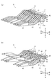
図1は、本実施形態におけるハンマー保持ユニット3を備える電子鍵盤楽器100の側断面図であり、図2は、ハンマー保持ユニット3の斜視図であって、(a)は全てのハンマー部材が初期状態のものであり、(b)はいくつかのハンマー部材が揺動した状態のものである。また、図3は、ハンマー保持ユニット3の側面図である。
図1に示すように、本実施形態における電子鍵盤楽器100は、楽器ケース101と、楽器ケース101内に収容された鍵盤装置1とを備えている。
FIG. 1 is a side sectional view of an
As shown in FIG. 1, the
鍵盤装置1は、電子鍵盤楽器100の左右方向(図1の紙面垂直方向)に並列に配列された複数の鍵2を備えている。
複数の鍵2は、白鍵2a及び黒鍵2bを有しており、それぞれ電子鍵盤楽器100の前後方向に延在するように配置されている。各鍵2は、後端部の回動軸21を中心に回動可能に構成されている。
The keyboard device 1 includes a plurality of
The plurality of
また、鍵盤装置1は、左右方向に配列された複数のハンマー保持ユニット3を備えている。
各ハンマー保持ユニット3は、図2(a),(b)に示すように、複数の鍵2に対応して設けられ、これら複数の鍵2それぞれにアクション荷重を付与する複数のハンマー部材4と、これら複数のハンマー部材4を保持するハンマー保持部材5とを備えている。
このハンマー保持ユニット3は、いくつか(例えば8〜10個)のハンマー部材4をブロック毎にまとめて個別に保持するものであり、当該ハンマー保持ユニット3が複数並べられることにより、全数(例えば88個)の鍵2に対応するハンマー部材4が配列されるようになっている。
Further, the keyboard device 1 includes a plurality of
As shown in FIGS. 2A and 2B, each
The
このうち、ハンマー部材4は、前後方向に長尺な形状に形成されており、軸支持部41と、鍵連結部42と、錘部43と、ハンマーアーム44とを有している。
軸支持部41は、ハンマー部材4のうち前端よりもやや後側に設けられ、ハンマー保持部材5に保持される部分である。この軸支持部41の左右両側面には回動軸41aが左右方向に突設されている。そして、この回動軸41aが後述するハンマー保持部材5の回動孔53に回動可能に嵌合されることにより、ハンマー部材4が回動軸41aを中心に上下方向に(つまり左右方向に垂直な面内で)回動するようになっている。
鍵連結部42は、軸支持部41から前方に突出した部分の先端(前端)に設けられている。この鍵連結部42は、当該ハンマー部材4に対応する鍵2の前端側に連結されており、この鍵2への押鍵操作に伴って下方に押し下げられるようになっている。
錘部43は、ハンマー部材4の後端部に設けられ、予め定められた重量を有している。
ハンマーアーム44は、軸支持部41と錘部43との間を連結する腕部である。このハンマーアーム44は、鍵2が押鍵操作されていない初期状態において、軸支持部41から後下がりに傾斜した後に屈曲して真っ直ぐ後方へ延在した形状に形成されている。
Of these, the
The
The key connecting
The
The
このような構成により、ハンマー部材4は、対応する鍵2への押鍵操作が行われると、当該鍵2に連結された鍵連結部42が押し下げられ、軸支持部41の回動軸41aを中心に錘部43が上昇する方向に回動する。また、押鍵操作が止んで離鍵されると、ハンマー部材4は、錘部43の自重によって当該錘部43が下降する方向に回動し、鍵2が押鍵操作されていない初期状態に復帰する。
With such a configuration, when the
一方、ハンマー保持部材5は、略平板状のベース板51上に、複数のハンマー部材4に対応して設けられた複数の嵌合部52を有している。
この嵌合部52は、左右方向に並設された2つの側板を有し、これら2つの側板の間にハンマー部材4が嵌合されるように構成されている。嵌合部52の左右両側板にはそれぞれ回動孔53が形成されており、この回動孔53にハンマー部材4の回動軸41aが嵌合されることにより、ハンマー部材4が回動軸41aを中心に回動可能に支持されるようになっている。複数の嵌合部52における回動孔53は互いの中心軸を一致させており、これにより、ハンマー保持部材5は、複数のハンマー部材4を共通の回転軸回りに個別に回動可能なように保持している。
また、嵌合部52は左右方向に規定の間隔で並設されており、これにより、ハンマー保持部材5は、複数のハンマー部材4を左右方向に規定の間隔で保持するように構成されている。
On the other hand, the
The
Further, the
このハンマー保持ユニット3は、鍵盤装置1(電子鍵盤楽器100)内に組み込まれた状態においては、図3に示すように、鍵2が押鍵操作されておらず錘部43が下限位置に位置した初期状態Plと、鍵2が押鍵操作されて錘部43が上限位置に位置した押鍵状態Puとの間で、各ハンマー部材4を上下に揺動(回動)させるように構成されている。
より詳しくは、ハンマー部材4は、鍵盤装置1のシャーシ6に設けられた上限ストッパ61及び下限ストッパ62により、鍵盤装置1内での揺動範囲が規制される(図1参照)。つまり、ハンマー部材4は、錘部43が下限ストッパ62に上方から当接することにより下限位置が初期状態Plのものに規制され、錘部43が上限ストッパ61に下方から当接することにより上限位置が押鍵状態Puのものに規制されるようになっている。
When the
More specifically, in the
また、ハンマー保持ユニット3は、鍵盤装置1(電子鍵盤楽器100)内に組み込まれていない単体の状態では、各ハンマー部材4を、初期状態Plから押鍵状態Puまでの通常使用時の揺動範囲から外れた仮固定状態Pfに保持できるように構成されている。この仮固定状態Pfは、錘部43を初期状態Plからさらに下降させた状態である。
Further, in the state where the
ここで、ハンマー部材4を仮固定状態Pfに保持するハンマー保持ユニット3の仮固定構造について説明する。
図4は、ハンマー保持ユニット3の仮固定構造を説明するための図である。
図4(a)に示すように、ハンマー部材4は、ハンマーアーム44のうち、後下がりに傾斜した前半部分の中程の位置における下端部に、左右両方向に突出した突起部45を有している(図3参照)。この突起部45の左右両端面は、略半球状に丸みを帯びた形状に形成されている。
一方、ハンマー保持部材5は、図4(b)に示すように、ベース板51の後端部のうち、嵌合部52以外の部分(つまり嵌合部52よりも左右両側の部分)が後方に延出されてなる延出部55を有している。この延出部55は、左右方向における嵌合部52の内側を向いた内側面の後端に、当該嵌合部52の内側向きに突出した係止部55aを有している。係止部55aは、ハンマー部材4を回動軸41a回りに回動させたときに、ハンマーアーム44の突起部45と当接するように設けられるとともに、当該突起部45が乗り越えやすいように前後両側がR面取りされている。
ハンマー保持部材5に設けられた2つの係止部55aと、ハンマー部材4に設けられた2つの突起部45の互いに当接する部分の夫々の間隔は、次のような関係となるように設定されている。つまり、係止部55aが弾性変形していない状態での2つの係止部55aの当接部分の間隔は、2つの突起部45の当接部分の間隔よりも狭く設定されており、係止部55aが弾性変形することにより2つの係止部55aの当接部分の間隔が、2つの突起部45の当接部分の間隔よりも広くなるように設定されている。
Here, the temporary fixing structure of the
FIG. 4 is a diagram for explaining a temporary fixing structure of the
As shown in FIG. 4A, the
On the other hand, as shown in FIG. 4B, the
The distances between the two locking
このような構成により、ハンマー保持ユニット3では、錘部43を初期状態Plから下降させるようにハンマー部材4を回動させたときに、ハンマーアーム44の突起部45とハンマー保持部材5の係止部55aとが当接する。そして、この状態からさらにハンマー部材4を同方向に回動させると、図4(c)に示すように、ハンマーアーム44の突起部45がハンマー保持部材5の係止部55aを弾性変形させつつ乗り越えて当該係止部55aに係止され、ハンマー部材4が揺動を規制された仮固定状態Pfとなる。
また、この仮固定状態Pfから錘部43を上昇させる方向にハンマー部材4を回動させると、この方向にハンマーアーム44の突起部45がハンマー保持部材5の係止部55aを弾性変形させつつ乗り越えて当該係止部55aによる係止が解除される。これにより、ハンマー部材4は仮固定が解除され、仮固定状態Pfから揺動可能な状態に復帰する。
つまり、ハンマー保持ユニット3では、各ハンマー部材4が仮固定された仮固定状態Pfと、この仮固定が解除された状態とを取り得るように、ハンマー保持部材5が複数のハンマー部材4を保持している。また、ハンマー保持部材5は、ハンマー部材4を仮固定状態Pfとその解除状態とに相互に遷移させることが可能となっている。
なお、突起部45及び係止部55a(延出部55)の係脱にあたり、弾性変形するのはハンマー保持部材5側の係止部55aでなくともよく、突起部45及び係止部55aのうち少なくともいずれか一方が弾性変形するように構成されていればよい。
また、ハンマー保持部材5は、ハンマー部材4が仮固定状態Pfにあるときに、ハンマー部材4を任意の向きで保持した場合であっても、このハンマー部材4の自重によって仮固定状態Pfが解除されることのない強さでハンマー部材4を仮固定している。つまり、ハンマー部材4の突起部45とハンマー保持部材5の係止部55aとは、ハンマー部材4の回動によって係脱可能であると同時に、ハンマー部材4がいかなる向きで係止されていてもその自重によって係止状態が簡単に解除されてしまわないように、適度な強さで互いに係止している。
With such a configuration, in the
Further, when the
That is, in the
When engaging and disengaging the
Further, in the
続いて、ハンマー保持ユニット3を鍵盤装置1(電子鍵盤楽器100)に組み込む組立手順について説明する。
図5は、この組立手順を説明するための図である。
なお、以下では、説明の簡単のために、鍵盤装置1のシャーシ6が、上限ストッパ61及び下限ストッパ62を有する上側シャーシ6U及び下側シャーシ6Lから構成されるものとし、図5においても、簡易的な形状の上側シャーシ6U及び下側シャーシ6Lを示している。
Subsequently, an assembly procedure for incorporating the
FIG. 5 is a diagram for explaining this assembly procedure.
In the following, for the sake of simplicity, it is assumed that the
まず、図5(a)に示すように、ハンマー保持ユニット3を、各ハンマー部材4が仮固定状態Pfに保持された状態で、上限ストッパ61を有する上側シャーシ6Uに組み付ける。
このとき、各ハンマー部材4は仮固定されており、自由に揺動して暴れることがないため、容易にハンマー保持ユニット3を上側シャーシ6Uに組み付けることができる。
First, as shown in FIG. 5A, the
At this time, since each
次に、図5(b)に示すように、下限ストッパ62を有する下側シャーシ6Lを、下側から上側シャーシ6Uに組み付ける。
このとき、下限ストッパ62が錘部43を上方に押圧することにより、各ハンマー部材4が錘部43を上昇させる方向に回動して仮固定状態Pfが解除され、ハンマー保持部材5により複数のハンマー部材4が個別に揺動可能に保持された状態となる。
Next, as shown in FIG. 5B, the
At this time, when the
そして、上側シャーシ6Uと下側シャーシ6Lを固定することにより、図5(c)に示すように、ハンマー部材4が初期状態Plと押鍵状態Puとの間で揺動可能な状態で、ハンマー保持ユニット3が鍵盤装置1のシャーシ6に組み付けられる。この状態では、ハンマー部材4は下限ストッパ62によって下限位置が規制されるため、仮固定状態Pfとなってしまうようなことはない。
Then, by fixing the
以上のように、本実施形態によれば、ハンマー部材4が仮固定状態Pfとこの仮固定が解除された状態とを取り得るように、ハンマー保持部材5がハンマー部材4を保持可能となっている。そのため、ハンマー保持ユニット3をシャーシ6に組み付ける際に、ハンマー部材4が自由に揺動して暴れることがない。
したがって、ハンマー部材4をシャーシ6に組み付ける際の作業性を向上させることができる。
As described above, according to the present embodiment, the
Therefore, workability when assembling the
また、ハンマー部材4の仮固定状態Pfの位置が、当該ハンマー部材4の通常使用時における揺動範囲から外れた位置であるので、ハンマー部材4が通常使用時においてこの位置で仮固定されてしまうことがない。
Further, since the position of the temporarily fixed state Pf of the
また、ハンマー部材4の突起部45が、当該ハンマー部材4の回動に伴ってハンマー保持部材5の係止部55aを弾性変形させて乗り越えることにより、当該係止部55aと係脱可能に構成されているので、ハンマー部材4を回動させるだけで容易に仮固定とその解除を行うことができる。
Further, the
また、ハンマー保持部材5が複数のハンマー部材4を個別に保持可能に構成されているので、複数のハンマー部材4をハンマー保持ユニット3としてまとめた状態でシャーシ6に組み付けることができ、さらに組立時の作業性を向上させることができる。
また、ハンマー保持部材5は、ハンマー部材4を仮固定状態Pfとその解除状態とに相互に遷移させることが可能となっている。すなわち、ハンマー保持ユニット3を、鍵盤装置1に組み込んだ状態から単体の状態に復帰させたときには、再びハンマー部材4を仮固定状態Pfにすることが可能となっている。これにより、鍵盤装置1(電子鍵盤楽器100)の分解時やその後の再組立時にも、ハンマー部材4を仮固定して作業性を向上させることができる。
Further, since the
Further, the
また、ハンマー保持ユニット3は、下限ストッパ62を有する下側シャーシ6Lに組み付けたときに、ハンマー部材4が下限ストッパ62に押圧されることで仮固定状態Pfが解除される。
これにより、ハンマー部材4の仮固定状態Pfを解除するためだけの解除作業を行う必要がなく、より一層組立時の作業性を向上させることができる。
Further, when the
As a result, it is not necessary to perform the release work only for releasing the temporarily fixed state Pf of the
なお、ハンマー部材4の組み付けに伴ってその仮固定状態Pfを解除するものは、下限ストッパ62を有する鍵盤装置1の部品であればシャーシ6(下側シャーシ6L)でなくともよい。
さらに言えば、この仮固定状態Pfを解除するものは下限ストッパ62でなくともよく、鍵盤装置1(電子鍵盤楽器100)内の他の部品等であってもよい。
It should be noted that the one that releases the temporarily fixed state Pf with the assembly of the
Furthermore, the one that releases the temporarily fixed state Pf does not have to be the
[第2の実施形態]
続いて、図6を参照して、本発明に係るハンマー保持ユニット及びこれを備える鍵盤装置の第2の実施形態について説明する。
なお、第2の実施形態は、ハンマー保持ユニットの仮固定構造が第1の実施形態と異なるものであるため、以下では、特に第1の実施形態と異なる点について説明する。
[Second Embodiment]
Subsequently, with reference to FIG. 6, a second embodiment of the hammer holding unit according to the present invention and the keyboard device including the hammer holding unit will be described.
Since the temporary fixing structure of the hammer holding unit is different from that of the first embodiment in the second embodiment, the points different from those of the first embodiment will be described below.
図6は、本実施形態におけるハンマー保持ユニット3の仮固定構造を説明するための図である。
図6(a)〜(c)に示すように、本実施形態におけるハンマー保持ユニット3では、ハンマー部材4が、第1の実施形態における突起部45に代えてリブ46を有しており、ハンマー保持部材5が、第1の実施形態における延出部55に代えて延出部56を有している。
FIG. 6 is a diagram for explaining a temporary fixing structure of the
As shown in FIGS. 6A to 6C, in the
このうち、ハンマー部材4のリブ46は、ハンマーアーム44の一方の側面のうち、軸支持部41近くの基端部に、仮固定状態Pfにおいて急峻な後上がりに傾斜するように立設されている。
一方、ハンマー保持部材5の延出部56は、ベース板51の後端部のうち、嵌合部52よりも一方の側面側の部分が後方に延出されて構成されている。この延出部56は、左右方向における嵌合部52の内側を向いた内側面の後端に、当該嵌合部52の内側向きに突出した係止部56aを有している。係止部56aは、ハンマー部材4を回動軸41a回りに回動させたときに、ハンマーアーム44のリブ46と当接するように設けられるとともに、当該リブ46が乗り越えやすいように前後両側がR面取りされている。
Of these, the
On the other hand, the extending
このような構成により、本実施形態におけるハンマー保持ユニット3は、第1の実施形態におけるものと同様に機能することができる。
すなわち、本実施形態におけるハンマー保持ユニット3では、錘部43を初期状態Plから下降させるようにハンマー部材4を回動させたときに、ハンマーアーム44のリブ46とハンマー保持部材5の係止部56aとが当接する。そして、この状態からさらにハンマー部材4を同方向に回動させると、ハンマーアーム44のリブ46がハンマー保持部材5の係止部56aを乗り越えて当該係止部56aに係止され、ハンマー部材4が揺動を規制された仮固定状態Pfとなる。
また、この仮固定状態Pfから錘部43を上昇させる方向にハンマー部材4を回動させると、この方向にハンマーアーム44のリブ46がハンマー保持部材5の係止部56aを乗り越えて当該係止部56aによる係止が解除され、仮固定状態Pfから揺動可能な状態に復帰する。
したがって、以上の第2の実施形態によれば、上述した第1の実施形態と同様の効果を得ることができる。
With such a configuration, the
That is, in the
Further, when the
Therefore, according to the second embodiment described above, the same effect as that of the first embodiment described above can be obtained.
[第3の実施形態]
続いて、図7を参照して、本発明に係るハンマー保持ユニット及びこれを備える鍵盤装置の第3の実施形態について説明する。
なお、第3の実施形態は、ハンマー保持ユニットの仮固定構造が第1の実施形態と異なるものであるため、以下では、特に第1の実施形態と異なる点について説明する。
[Third Embodiment]
Subsequently, with reference to FIG. 7, a third embodiment of the hammer holding unit according to the present invention and the keyboard device including the hammer holding unit will be described.
Since the temporary fixing structure of the hammer holding unit is different from that of the first embodiment in the third embodiment, the points different from those of the first embodiment will be described below.
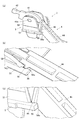
図7は、本実施形態におけるハンマー保持ユニット3の仮固定構造を説明するための図である。
図7(a)に示すように、本実施形態におけるハンマー保持ユニット3では、ハンマー部材4が、第1の実施形態における突起部45に代えて突設部47を有しており、ハンマー保持部材5が、第1の実施形態における延出部55に代えて係止リブ57を有している。
FIG. 7 is a diagram for explaining a temporary fixing structure of the
As shown in FIG. 7A, in the
このうち、ハンマー部材4の突設部47は、図7(b)に示すように、ハンマーアーム44のうち、軸支持部41近くの基端部の下部に形成された略L字状の切欠き44a内から、仮固定状態Pfにおいて前下がりに傾斜するように突設されている。この突設部47の一方の側面の先端(下端)には、緩やかに膨出させた円形の膨出部47aが設けられている。
一方、ハンマー保持部材5の係止リブ57は、図7(c)に示すように、ベース板51の下面の後端部に、やや後方に突出させつつ立設されている。この係止リブ57は、ハンマー部材4を回動軸41a回りに回動させたときに、ハンマーアーム44の突設部47と左右方向に隣接する位置に設けられている。また、係止リブ57は、ハンマーアーム44の膨出部47aの形状に対応した円形状の係止孔57aを有している。この係止孔57aは、図7(d)に示すように、ハンマー部材4を回動軸41a回りに回動させたときに、ハンマーアーム44の膨出部47aが嵌まるように設けられている。
Of these, the protruding
On the other hand, as shown in FIG. 7C, the locking
このような構成により、本実施形態におけるハンマー保持ユニット3は、第1の実施形態におけるものと同様に機能することができる。
すなわち、本実施形態におけるハンマー保持ユニット3では、錘部43を初期状態Plから下降させるようにハンマー部材4を回動させたときに、ハンマーアーム44の膨出部47aとハンマー保持部材5の係止リブ57の後端面とが当接する。そして、この状態からさらにハンマー部材4を同方向に回動させると、ハンマーアーム44の膨出部47aがハンマー保持部材5の係止孔57aに嵌まって係止され、ハンマー部材4が揺動を規制された仮固定状態Pfとなる。
また、この仮固定状態Pfから錘部43を上昇させる方向にハンマー部材4を回動させると、この方向にハンマーアーム44の膨出部47aがハンマー保持部材5の係止孔57aから外れて当該係止孔57aによる係止が解除され、仮固定状態Pfから揺動可能な状態に復帰する。
したがって、以上の第3の実施形態によれば、上述した第1の実施形態と同様の効果を得ることができる。
With such a configuration, the
That is, in the
Further, when the
Therefore, according to the above-mentioned third embodiment, the same effect as that of the above-mentioned first embodiment can be obtained.
[第4の実施形態]
続いて、図8を参照して、本発明に係るハンマー保持ユニット及びこれを備える鍵盤装置の第4の実施形態について説明する。
なお、第4の実施形態は、ハンマー保持ユニットの仮固定構造が第1の実施形態と異なるものであるため、以下では、特に第1の実施形態と異なる点について説明する。
[Fourth Embodiment]
Subsequently, a fourth embodiment of the hammer holding unit and the keyboard device including the hammer holding unit according to the present invention will be described with reference to FIG.
Since the temporary fixing structure of the hammer holding unit is different from that of the first embodiment in the fourth embodiment, the points different from those of the first embodiment will be described below.
図8は、本実施形態におけるハンマー保持ユニット3の仮固定構造を説明するための図である。
図8(a)に示すように、本実施形態におけるハンマー保持ユニット3では、ハンマー部材4が、第1の実施形態における突起部45に代えて舌部48を有しており、ハンマー保持部材5が、第1の実施形態における延出部55に代えて係止板58を有している。
FIG. 8 is a diagram for explaining a temporary fixing structure of the
As shown in FIG. 8A, in the
このうち、ハンマー部材4の舌部48は、図8(b)に示すように、ハンマーアーム44のうち、軸支持部41近くの基端部の下部に形成された略L字状の切欠き44b内から、仮固定状態Pfにおいて前方へ立設されている。この舌部48は、切欠き44bのうち、仮固定状態Pfにおける上辺よりもやや下側に設けられており、当該舌部48と切欠き44bの上辺との間に凹部49を画成している。
一方、ハンマー保持部材5の係止板58は、図8(c)に示すように、ベース板51の後端部を後方へ延出させるように、当該ベース板51の後端面から後方へ突設されている。この係止板58は、ハンマー部材4を回動軸41a回りに回動させたときに、ハンマーアーム44の舌部48と互いの先端で当接するように設けられている。
Of these, the
On the other hand, as shown in FIG. 8C, the locking
このような構成により、本実施形態におけるハンマー保持ユニット3は、第1の実施形態におけるものと同様に機能することができる。
すなわち、本実施形態におけるハンマー保持ユニット3では、錘部43を初期状態Plから下降させるようにハンマー部材4を回動させたときに、ハンマーアーム44の舌部48とハンマー保持部材5の係止板58との互いの先端が当接する。そして、この状態からさらにハンマー部材4を同方向に回動させると、ハンマーアーム44の舌部48がハンマー保持部材5の係止板58を乗り越えて凹部49内に係止され、ハンマー部材4が揺動を規制された仮固定状態Pfとなる。
また、この仮固定状態Pfから錘部43を上昇させる方向にハンマー部材4を回動させると、この方向にハンマーアーム44の舌部48がハンマー保持部材5の係止板58を乗り越えて当該係止板58による係止が解除され、仮固定状態Pfから揺動可能な状態に復帰する。
したがって、以上の第4の実施形態によれば、上述した第1の実施形態と同様の効果を得ることができる。
With such a configuration, the
That is, in the
Further, when the
Therefore, according to the fourth embodiment described above, the same effect as that of the first embodiment described above can be obtained.
なお、ハンマー保持ユニットの仮固定構造は、上述した第1〜第4の実施形態のものに限定されず、ハンマー部材4の回動に伴って当該ハンマー部材4とハンマー保持部材5の互いの係止部が係脱可能に構成されていればよい。
The temporary fixing structure of the hammer holding unit is not limited to that of the first to fourth embodiments described above, and the
また、ハンマー保持部材5は、ハンマー部材4が仮固定から解除された状態にあるときに、少なくともハンマー部材4を仮固定する位置を含まない2つの位置(上記実施形態における初期状態Plの位置と押鍵状態Puの位置)の範囲内で、当該ハンマー部材4を揺動可能に保持するように構成されていればよい。さらに言えば、ハンマー保持部材5がハンマー部材4を仮固定する位置は、ハンマー部材4の通常使用時の揺動範囲から外れた位置でなくともよい。
Further, the
以上、本発明のいくつかの実施形態を説明したが、本発明の範囲は、上述の実施の形態に限定するものではなく、特許請求の範囲に記載された発明の範囲とその均等の範囲を含む。
以下に、この出願の願書に最初に添付した特許請求の範囲に記載した発明を付記する。付記に記載した請求項の項番は、この出願の願書に最初に添付した特許請求の範囲の通りである。
〔付記〕
<請求項1>
鍵盤装置の鍵の動きに応じて前記鍵に荷重を付与するためのハンマー部材と、
前記ハンマー部材が第1の位置に仮固定された第1保持状態と、前記ハンマー部材の前記仮固定が解除された第2保持状態と、を取り得るように前記ハンマー部材を保持可能な保持部材と、
を備えるハンマー保持ユニット。
<請求項2>
前記保持部材は、複数の前記ハンマー部材を規定の間隔で保持することを特徴とする請求項1に記載のハンマー保持ユニット。
<請求項3>
前記ハンマー部材が前記第2保持状態にあるときに、前記保持部材は、複数の前記ハンマー部材を個別に揺動可能に保持することを特徴とする請求項2に記載のハンマー保持ユニット。
<請求項4>
前記ハンマー部材が前記第2保持状態にあるときに、前記保持部材は、少なくとも前記第1の位置を含まない第2の位置から第3の位置までの範囲内で前記ハンマー部材を揺動可能に保持することを特徴とする請求項1から請求項3のいずれか一項に記載のハンマー保持ユニット。
<請求項5>
前記保持部材は、前記ハンマー部材を前記第1保持状態と前記第2保持状態とに相互に遷移させることが可能であることを特徴とする請求項1から請求項4のいずれか一項に記載のハンマー保持ユニット。
<請求項6>
前記第1の位置は、前記ハンマー保持ユニットを前記鍵盤楽器に組み込んだ状態での通常使用時における前記ハンマー部材の揺動範囲から外れた位置であることを特徴とする請求項1から請求項5のいずれか一項に記載のハンマー保持ユニット。
<請求項7>
前記ハンマー部材及び前記保持部材は、前記ハンマー部材が前記第1の位置のときに互いに係止する係止部を有することを特徴とする請求項1から請求項6のいずれか一項に記載のハンマー保持ユニット。
<請求項8>
前記ハンマー部材及び前記保持部材は、前記係止部として、いずれか一方に突起部、他方に突起受け部を有し、
前記係止部は、前記ハンマー部材の揺動に伴って前記突起部及び前記突起受け部のうちいずれか一方が弾性変形して他方を乗り越えることにより、前記突起部と前記突起受け部とが係脱可能に構成されていることを特徴とする請求項7に記載のハンマー保持ユニット。
<請求項9>
前記保持部材が複数の前記ハンマー部材を共通の回転軸により個別に回動可能に保持するように構成されていることを特徴とする請求項1から請求項8のいずれか一項に記載のハンマー保持ユニット。
<請求項10>
前記保持部材は、前記ハンマー部材が前記第1保持状態にあるときに、前記ハンマー部材を任意の向きで保持した場合であっても、前記ハンマー部材の自重によって前記第1保持状態が解除されることのない強さで前記ハンマー部材を仮固定していることを特徴とする請求項1から請求項9のいずれか一項に記載のハンマー保持ユニット。
<請求項11>
請求項1から請求項10のいずれか一項に記載のハンマー保持ユニットと、
前記ハンマー部材に対応する鍵と、
前記ハンマー保持ユニットが組み込まれた状態で前記ハンマー部材の揺動範囲を規制する規制部材を有する筐体部材と、
を備え、
前記第1の位置は、前記規制された揺動範囲の外に位置することを特徴とする鍵盤装置。
<請求項12>
前記ハンマー保持ユニットは、前記筐体部材に組み付けたときに、前記ハンマー部材が前記規制部材に押圧されることで前記第1の位置に固定された状態が解除されるように構成されていることを特徴とする請求項11に記載の鍵盤装置。
Although some embodiments of the present invention have been described above, the scope of the present invention is not limited to the above-described embodiments, but the scope of the invention described in the claims and the equivalent range thereof. include.
The inventions described in the claims originally attached to the application of this application are added below. The claims in the appendix are as specified in the claims originally attached to the application for this application.
[Additional Notes]
<Claim 1>
A hammer member for applying a load to the key according to the movement of the key of the keyboard device, and
A holding member capable of holding the hammer member so as to have a first holding state in which the hammer member is temporarily fixed at a first position and a second holding state in which the temporary fixing of the hammer member is released. When,
Hammer holding unit with.
<Claim 2>
The hammer holding unit according to claim 1, wherein the holding member holds a plurality of the hammer members at predetermined intervals.
<Claim 3>
The hammer holding unit according to
<Claim 4>
When the hammer member is in the second holding state, the holding member can swing the hammer member within a range from a second position to a third position that does not include at least the first position. The hammer holding unit according to any one of claims 1 to 3, wherein the hammer holding unit is held.
<Claim 5>
The holding member according to any one of claims 1 to 4, wherein the hammer member can mutually transition between the first holding state and the second holding state. Hammer holding unit.
<Claim 6>
Claims 1 to 5 are characterized in that the first position is a position outside the swing range of the hammer member during normal use in a state where the hammer holding unit is incorporated in the keyboard instrument. The hammer holding unit according to any one of the above.
<Claim 7>
The method according to any one of claims 1 to 6, wherein the hammer member and the holding member have a locking portion that locks each other when the hammer member is in the first position. Hammer holding unit.
<Claim 8>
The hammer member and the holding member have a protrusion on one side and a protrusion receiving part on the other side as the locking portion.
In the locking portion, one of the protrusion and the protrusion receiving portion is elastically deformed as the hammer member swings, and the other is overcome, so that the protrusion and the protrusion receiving portion are engaged with each other. The hammer holding unit according to claim 7, wherein the hammer holding unit is detachably configured.
<Claim 9>
The hammer according to any one of claims 1 to 8, wherein the holding member is configured to individually and rotatably hold a plurality of the hammer members by a common rotation shaft. Holding unit.
<Claim 10>
The holding member is released from the first holding state by its own weight even when the hammer member is held in an arbitrary direction when the hammer member is in the first holding state. The hammer holding unit according to any one of claims 1 to 9, wherein the hammer member is temporarily fixed with a strength that does not occur.
<Claim 11>
The hammer holding unit according to any one of claims 1 to 10.
The key corresponding to the hammer member and
A housing member having a regulating member that regulates the swing range of the hammer member with the hammer holding unit incorporated, and a housing member.
With
The first position is a keyboard device characterized by being located outside the regulated swing range.
<Claim 12>
The hammer holding unit is configured so that when the hammer member is assembled to the housing member, the hammer member is pressed against the restricting member to release the state of being fixed at the first position. 11. The keyboard device according to claim 11.
1 鍵盤装置
2 鍵
3 ハンマー保持ユニット
4 ハンマー部材
5 ハンマー保持部材
6 シャーシ
41a 回動軸
43 錘部
44 ハンマーアーム
45 突起部
46 リブ
47 突設部
47a 膨出部
48 舌部
49 凹部
55 延出部
55a 係止部
56 延出部
56a 係止部
57 係止リブ
57a 係止孔
58 係止板
61 上限ストッパ
62 下限ストッパ
Pf 仮固定状態
Pl 初期状態
Pu 押鍵状態
1
Claims (11)
前記複数のハンマー部材が第1の位置に仮固定された第1保持状態と、前記複数のハンマー部材の前記仮固定が解除された第2保持状態と、を取り得るように前記ハンマー部材を保持可能な保持部材と、
を備え、
前記複数のハンマー部材及び前記保持部材は、前記複数のハンマー部材が前記第1の位置のときに互いに係止する係止部として、いずれか一方に突起部、他方に突起受け部を有し、
前記係止部は、前記複数のハンマー部材の揺動に伴って前記突起部及び前記突起受け部のうちいずれか一方が弾性変形して他方を乗り越えることにより、前記突起部と前記突起受け部とが係脱可能に構成されている、
ハンマー保持ユニット。 A plurality of hammer members for applying a load to each of the plurality of keys according to the movement of each of the plurality of keys in the keyboard instrument.
The hammer member is held so as to be able to take a first holding state in which the plurality of hammer members are temporarily fixed at the first position and a second holding state in which the temporary fixing of the plurality of hammer members is released. With possible holding members
Bei to give a,
The plurality of hammer members and the holding member have a protrusion on one side and a protrusion receiving portion on the other side as locking portions for locking each other when the plurality of hammer members are in the first position.
The locking portion includes the protrusion and the protrusion receiving portion by elastically deforming one of the protrusion and the protrusion receiving portion with the swing of the plurality of hammer members and overcoming the other. Is configured to be detachable,
Hammer holding unit.
前記複数のハンマー部材が第1の位置に仮固定された第1保持状態と、前記複数のハンマー部材の前記仮固定が解除された第2保持状態と、を取り得るように前記ハンマー部材を保持可能な保持部材と、
を備え、
前記複数のハンマー部材が前記第2保持状態にあるときに、前記保持部材は、少なくとも前記第1の位置を含まない第2の位置から第3の位置までの範囲内で前記複数のハンマー部材を揺動可能に保持する、
ハンマー保持ユニット。 A plurality of hammer members for applying a load to each of the plurality of keys according to the movement of each of the plurality of keys in the keyboard instrument.
The hammer member is held so as to be able to take a first holding state in which the plurality of hammer members are temporarily fixed at the first position and a second holding state in which the temporary fixing of the plurality of hammer members is released. With possible holding members
Bei to give a,
When the plurality of hammer members are in the second holding state, the holding member holds the plurality of hammer members within a range from a second position to a third position that does not include at least the first position. Hold swingable,
Hammer holding unit.
前記複数のハンマー部材が第1の位置に仮固定された第1保持状態と、前記複数のハンマー部材の前記仮固定が解除された第2保持状態と、を取り得るように前記ハンマー部材を保持可能な保持部材と、
を備え、
前記第1の位置は、前記ハンマー保持ユニットを前記鍵盤楽器に組み込んだ状態での通常使用時における前記ハンマー部材の揺動範囲から外れた位置である、
ハンマー保持ユニット。 A plurality of hammer members for applying a load to each of the plurality of keys according to the movement of each of the plurality of keys in the keyboard instrument.
The hammer member is held so as to be able to take a first holding state in which the plurality of hammer members are temporarily fixed at the first position and a second holding state in which the temporary fixing of the plurality of hammer members is released. With possible holding members
Bei to give a,
The first position is a position outside the swing range of the hammer member during normal use with the hammer holding unit incorporated in the keyboard instrument.
Hammer holding unit.
前記複数のハンマー部材が第1の位置に仮固定された第1保持状態と、前記複数のハンマー部材の前記仮固定が解除された第2保持状態と、を取り得るように前記ハンマー部材を保持可能な保持部材と、
を備え、
前記保持部材は、前記ハンマー部材が前記第1保持状態にあるときに、前記ハンマー部材を任意の向きで保持した場合であっても、前記ハンマー部材の自重によって前記第1保持状態が解除されることのない強さで前記ハンマー部材を仮固定している、
ハンマー保持ユニット。 A plurality of hammer members for applying a load to each of the plurality of keys according to the movement of each of the plurality of keys in the keyboard instrument.
The hammer member is held so as to be able to take a first holding state in which the plurality of hammer members are temporarily fixed at the first position and a second holding state in which the temporary fixing of the plurality of hammer members is released. With possible holding members
Bei to give a,
The holding member is released from the first holding state by its own weight even when the hammer member is held in an arbitrary direction when the hammer member is in the first holding state. Temporarily fixing the hammer member with unprecedented strength,
Hammer holding unit.
前記複数の鍵それぞれの動きに応じて前記複数の鍵それぞれに荷重を付与する複数のハンマー部材と、前記複数のハンマー部材をそれぞれ揺動可能に保持する保持部材と、を含むハンマー保持ユニットと、
前記複数のハンマー部材の揺動範囲を規制する規制部材を有する筐体部材と、
を含み、
前記ハンマー保持ユニットが前記筺体部材に組み込まれていない状態では、前記保持部材は、前記揺動範囲の範囲外の第1の位置で前記複数のハンマー部材が仮固定されており、
前記ハンマー保持ユニットが前記筺体部材に組み込まれている状態では、前記保持部材は、前記仮固定が解除された状態で、前記揺動範囲の範囲内で前記複数のハンマー部材をそれぞれ揺動可能に保持している、
鍵盤装置。 With multiple keys
A hammer holding unit including a plurality of hammer members that apply a load to each of the plurality of keys according to the movement of each of the plurality of keys, and a holding member that holds the plurality of hammer members swingably.
A housing member having a regulating member that regulates the swing range of the plurality of hammer members, and a housing member.
Including
In a state where the hammer holding unit is not incorporated in the housing member, the holding member is temporarily fixed with the plurality of hammer members at a first position outside the swing range.
In the state where the hammer holding unit is incorporated in the housing member, the holding member can swing the plurality of hammer members within the swing range in the state where the temporary fixing is released. keeping,
Keyboard device.
前記制限範囲は、前記仮固定が解除された状態で前記ハンマー部材が揺動可能な範囲よりも狭い、請求項9に記載の鍵盤装置。 The restricting member includes an upper limit stopper and a lower limit stopper that restrict each of the plurality of hammer members from swinging beyond the limiting range in response to a corresponding key pressing operation.
The keyboard device according to claim 9 , wherein the limited range is narrower than a range in which the hammer member can swing in a state where the temporary fixing is released.
Priority Applications (3)
| Application Number | Priority Date | Filing Date | Title |
|---|---|---|---|
| JP2017136751A JP6965607B2 (en) | 2017-07-13 | 2017-07-13 | Hammer holding unit and keyboard device |
| US16/032,851 US10546567B2 (en) | 2017-07-13 | 2018-07-11 | Hammer unit and keyboard instrument |
| CN201810767997.1A CN109256112B (en) | 2017-07-13 | 2018-07-13 | Hammer unit and keyboard device |
Applications Claiming Priority (1)
| Application Number | Priority Date | Filing Date | Title |
|---|---|---|---|
| JP2017136751A JP6965607B2 (en) | 2017-07-13 | 2017-07-13 | Hammer holding unit and keyboard device |
Publications (3)
| Publication Number | Publication Date |
|---|---|
| JP2019020497A JP2019020497A (en) | 2019-02-07 |
| JP2019020497A5 JP2019020497A5 (en) | 2020-08-20 |
| JP6965607B2 true JP6965607B2 (en) | 2021-11-10 |
Family
ID=64999700
Family Applications (1)
| Application Number | Title | Priority Date | Filing Date |
|---|---|---|---|
| JP2017136751A Active JP6965607B2 (en) | 2017-07-13 | 2017-07-13 | Hammer holding unit and keyboard device |
Country Status (3)
| Country | Link |
|---|---|
| US (1) | US10546567B2 (en) |
| JP (1) | JP6965607B2 (en) |
| CN (1) | CN109256112B (en) |
Families Citing this family (4)
| Publication number | Priority date | Publication date | Assignee | Title |
|---|---|---|---|---|
| JP2018156039A (en) * | 2017-03-21 | 2018-10-04 | カシオ計算機株式会社 | Hammer unit and keyboard device |
| JP6965607B2 (en) * | 2017-07-13 | 2021-11-10 | カシオ計算機株式会社 | Hammer holding unit and keyboard device |
| JP6795022B2 (en) * | 2018-10-18 | 2020-12-02 | カシオ計算機株式会社 | Keyboard instrument |
| JP7346949B2 (en) * | 2019-07-08 | 2023-09-20 | ヤマハ株式会社 | Keyboards, keyboard parts |
Family Cites Families (19)
| Publication number | Priority date | Publication date | Assignee | Title |
|---|---|---|---|---|
| US2958249A (en) * | 1954-06-22 | 1960-11-01 | Joseph Dvorak | String mounted key for electronic musical instrument |
| US3426636A (en) * | 1967-06-06 | 1969-02-11 | Starck Piano Co | Portable piano assembly |
| US4254684A (en) * | 1979-01-25 | 1981-03-10 | Helpinstill Iii Charles T | Breakdown piano |
| JP2550104Y2 (en) | 1992-03-10 | 1997-10-08 | 株式会社河合楽器製作所 | Hammer fixing device for keyboard instruments |
| JP3256447B2 (en) * | 1996-10-30 | 2002-02-12 | 株式会社河合楽器製作所 | Keyboard device |
| JP4270177B2 (en) * | 2005-07-21 | 2009-05-27 | ヤマハ株式会社 | Keyboard device |
| JP5169681B2 (en) * | 2008-09-25 | 2013-03-27 | ヤマハ株式会社 | Keyboard device |
| US8134060B2 (en) * | 2009-06-30 | 2012-03-13 | Casio Computer Co., Ltd | Electronic keyboard instrument |
| JP5659525B2 (en) * | 2010-03-24 | 2015-01-28 | ヤマハ株式会社 | Keyboard device |
| JP5864188B2 (en) | 2011-09-30 | 2016-02-17 | 株式会社河合楽器製作所 | Attachment structure of let-off giving member for electronic keyboard instrument |
| CN104115219B (en) * | 2011-12-15 | 2017-06-23 | 雅马哈株式会社 | Method for the actuator of soundboard vibration allowed in musical instrument and for actuating it |
| US9006549B2 (en) * | 2011-12-16 | 2015-04-14 | Kabushiki Kaisha Kawai Gakki Seisakusho | Hammer device and keyboard device for electronic keyboard instrument |
| US8987570B2 (en) * | 2012-07-02 | 2015-03-24 | Yamaha Corporation | Keyboard device for electronic musical instrument |
| JP6523019B2 (en) | 2015-03-31 | 2019-05-29 | ローランド株式会社 | Electronic musical instrument keyboard device |
| JP6857327B2 (en) * | 2017-03-17 | 2021-04-14 | カシオ計算機株式会社 | Keyboard devices and keyboard instruments |
| JP2018156039A (en) * | 2017-03-21 | 2018-10-04 | カシオ計算機株式会社 | Hammer unit and keyboard device |
| JP6930258B2 (en) * | 2017-07-12 | 2021-09-01 | カシオ計算機株式会社 | Keyboard device |
| JP6965607B2 (en) * | 2017-07-13 | 2021-11-10 | カシオ計算機株式会社 | Hammer holding unit and keyboard device |
| JP7027717B2 (en) * | 2017-08-01 | 2022-03-02 | カシオ計算機株式会社 | Reaction force generator and electronic keyboard instrument |
-
2017
- 2017-07-13 JP JP2017136751A patent/JP6965607B2/en active Active
-
2018
- 2018-07-11 US US16/032,851 patent/US10546567B2/en active Active
- 2018-07-13 CN CN201810767997.1A patent/CN109256112B/en active Active
Also Published As
| Publication number | Publication date |
|---|---|
| CN109256112A (en) | 2019-01-22 |
| JP2019020497A (en) | 2019-02-07 |
| US10546567B2 (en) | 2020-01-28 |
| CN109256112B (en) | 2024-02-13 |
| US20190019483A1 (en) | 2019-01-17 |
Similar Documents
| Publication | Publication Date | Title |
|---|---|---|
| JP6965607B2 (en) | Hammer holding unit and keyboard device | |
| JP5369946B2 (en) | Electronic musical instrument keyboard device | |
| JP4839969B2 (en) | Keyboard device | |
| JP6805953B2 (en) | Terminal block | |
| US9495940B2 (en) | Keyboard device and keyboard instrument | |
| JP6801516B2 (en) | Terminal block | |
| JPH08314439A (en) | Keyboard device | |
| JP2018156039A (en) | Hammer unit and keyboard device | |
| JP2019020453A (en) | Keyboard device | |
| JP2007052401A (en) | Keyboard apparatus | |
| JP6142725B2 (en) | Electronic musical instrument keyboard device | |
| JP6673454B2 (en) | Method of manufacturing keyboard instruments | |
| JP2019053107A (en) | Keyboard device | |
| JP2023050759A (en) | Keyboard device of keyboard musical instrument | |
| JP6315211B2 (en) | Keyboard instrument | |
| JP7416189B2 (en) | keyboard instrument | |
| JP2006003495A (en) | Keyboard device | |
| JP2023050758A (en) | Keyboard device of keyboard musical instrument | |
| JP2023050755A (en) | Keyboard device for keyboard musical instrument | |
| JP2022152007A (en) | Keyboard device of keyboard musical instrument | |
| CN106504733B (en) | Support structure | |
| JP6819447B2 (en) | Keyboard instrument | |
| JP2023050757A (en) | Keyboard device for keyboard musical instrument | |
| JP2022152008A (en) | Keyboard device of keyboard musical instrument | |
| JP2001337678A (en) | Keyboard device |
Legal Events
| Date | Code | Title | Description |
|---|---|---|---|
| A521 | Request for written amendment filed |
Free format text: JAPANESE INTERMEDIATE CODE: A523 Effective date: 20200701 |
|
| A621 | Written request for application examination |
Free format text: JAPANESE INTERMEDIATE CODE: A621 Effective date: 20200701 |
|
| A977 | Report on retrieval |
Free format text: JAPANESE INTERMEDIATE CODE: A971007 Effective date: 20210416 |
|
| A131 | Notification of reasons for refusal |
Free format text: JAPANESE INTERMEDIATE CODE: A131 Effective date: 20210427 |
|
| A521 | Request for written amendment filed |
Free format text: JAPANESE INTERMEDIATE CODE: A523 Effective date: 20210617 |
|
| TRDD | Decision of grant or rejection written | ||
| A01 | Written decision to grant a patent or to grant a registration (utility model) |
Free format text: JAPANESE INTERMEDIATE CODE: A01 Effective date: 20210921 |
|
| A61 | First payment of annual fees (during grant procedure) |
Free format text: JAPANESE INTERMEDIATE CODE: A61 Effective date: 20211004 |
|
| R150 | Certificate of patent or registration of utility model |
Ref document number: 6965607 Country of ref document: JP Free format text: JAPANESE INTERMEDIATE CODE: R150 |