JP6962115B2 - Liquid discharge device - Google Patents

Liquid discharge device Download PDF

Info

Publication number
JP6962115B2
JP6962115B2 JP2017189838A JP2017189838A JP6962115B2 JP 6962115 B2 JP6962115 B2 JP 6962115B2 JP 2017189838 A JP2017189838 A JP 2017189838A JP 2017189838 A JP2017189838 A JP 2017189838A JP 6962115 B2 JP6962115 B2 JP 6962115B2
Authority
JP
Japan
Prior art keywords
discharge
nozzle
ink
liquid
viscosity
Prior art date
Legal status (The legal status is an assumption and is not a legal conclusion. Google has not performed a legal analysis and makes no representation as to the accuracy of the status listed.)
Active
Application number
JP2017189838A
Other languages
Japanese (ja)
Other versions
JP2019064061A (en
Inventor
幹生 小川
Current Assignee (The listed assignees may be inaccurate. Google has not performed a legal analysis and makes no representation or warranty as to the accuracy of the list.)
Brother Industries Ltd
Original Assignee
Brother Industries Ltd
Priority date (The priority date is an assumption and is not a legal conclusion. Google has not performed a legal analysis and makes no representation as to the accuracy of the date listed.)
Filing date
Publication date
Application filed by Brother Industries Ltd filed Critical Brother Industries Ltd
Priority to JP2017189838A priority Critical patent/JP6962115B2/en
Publication of JP2019064061A publication Critical patent/JP2019064061A/en
Application granted granted Critical
Publication of JP6962115B2 publication Critical patent/JP6962115B2/en
Active legal-status Critical Current
Anticipated expiration legal-status Critical

Links

Images

Description

本発明は、液体吐出装置に関する。 The present invention relates to a liquid discharge device.

特許文献1には、液体吐出装置の一例として、インク(液体)を吐出するノズルを有するヘッドを備えたインクジェットプリンタが開示されている。この種のインクジェットプリンタでは、ノズル内のインクが増粘すると、例えば、所望の吐出量のインクが吐出されなかったり、所望の着弾位置にインクが着弾しなかったりして、ノズルの吐出性が低下する。そこで、特許文献1のインクジェットプリンタでは、ノズルからインクを排出するパージ処理(排出処理)を、定期的に実行している。また、この特許文献1のインクジェットプリンタでは、ノズルの吐出性を確実に回復させるために、ノズルから排出されるインクの粘度が高くなるほど、パージ処理の際に排出させるインクの排出量を増やしている。 Patent Document 1 discloses an inkjet printer including a head having a nozzle for ejecting ink (liquid) as an example of a liquid ejection device. In this type of inkjet printer, when the ink in the nozzle is thickened, for example, the desired amount of ink is not ejected or the ink does not land at the desired landing position, resulting in a decrease in nozzle ejection performance. do. Therefore, in the inkjet printer of Patent Document 1, a purge process (discharge process) for discharging ink from a nozzle is periodically executed. Further, in the inkjet printer of Patent Document 1, in order to surely restore the ejection property of the nozzle, the higher the viscosity of the ink ejected from the nozzle, the larger the amount of ink ejected during the purge process. ..

特開2016−190468号公報Japanese Unexamined Patent Publication No. 2016-190468

ところで、この種の液体吐出装置には、上記排出処理として、被記録媒体に対して液体を吐出して画像を印刷する印刷処理の直前に実行する印刷前排出処理や、定期的に実行する定期排出処理等、複数種類の排出処理を実行可能なものが知られている。本願発明者は、鋭意検討したところ、このような複数種類の排出処理の中には、ノズルの吐出性の低下を抑制できればよく、ノズルの吐出性を回復させる必要が必ずしもない排出処理があることを見出した。例えば、印刷前排出処理及び定期排出処理を実行可能に構成されている場合、印刷処理の開始時にはノズルの吐出性が回復している必要があるため、印刷前排出処理では、ノズルの吐出性を回復させる必要はある。しかしながら、定期排出処理については、印刷処理の開始時には上記印刷前排出処理によりノズルの吐出性が回復されるため、当該定期排出処理によりノズルの吐出性を完全に回復させる必要はない。 By the way, in this type of liquid discharge device, as the discharge process, a pre-print discharge process executed immediately before a print process of discharging a liquid to a recording medium and printing an image, or a periodical execution process is performed periodically. Those capable of executing a plurality of types of discharge treatment such as discharge treatment are known. As a result of diligent studies, the inventor of the present application has found that among such a plurality of types of discharge treatments, there is a discharge treatment that only needs to suppress a decrease in nozzle discharge performance and does not necessarily require recovery of nozzle discharge performance. I found. For example, when the pre-printing discharge process and the periodic discharge process are configured to be executable, the nozzle ejection property must be restored at the start of the printing process. Therefore, in the pre-printing ejection process, the nozzle ejection property is improved. It needs to be recovered. However, with regard to the periodic ejection process, since the ejection property of the nozzle is restored by the pre-printing ejection process at the start of the printing process, it is not necessary to completely restore the nozzle ejection property by the periodic ejection process.

このような、吐出性を回復させる必要がない排出処理においても、液体の粘度が高くなったときに、液体の排出量を多くする等の排出条件を変更すると、当該排出条件の変更に係る処理負担が増大したり、液体の消費量が増えたりする問題が生じる。 Even in such a discharge process in which it is not necessary to restore the discharge property, if the discharge conditions such as increasing the discharge amount of the liquid are changed when the viscosity of the liquid becomes high, the process related to the change of the discharge conditions. Problems such as increased burden and increased liquid consumption arise.

そこで、本発明の目的は、排出処理に関する処理負担を低減可能であり、且つ液体の消費量が増大することを抑制可能な液体吐出装置を提供することである。 Therefore, an object of the present invention is to provide a liquid discharge device capable of reducing the processing load related to the discharge treatment and suppressing an increase in the consumption of the liquid.

上記の課題を解決するために、本発明の液体吐出装置は、液体を吐出するノズルを有するヘッドと、液体排出部と、制御部とを備え、前記制御部は、前記ノズルから液体を排出させる際に前記ノズルの吐出性の回復に必要な最小限の排出量以上の排出量で排出させるような第1排出条件で、前記液体排出部を制御する第1排出処理と、前記ノズルから液体を排出させる際に前記ノズルの吐出性の回復に必要な最小限の排出量よりも少ない排出量で排出させるような第2排出条件で、前記液体排出部を制御する第2排出処理と、を実行可能であり、さらに、前記制御部は、前記ヘッド内の液体の粘度に関する粘度情報を取得する粘度情報取得処理と、前記粘度情報取得処理により取得した前記粘度情報に応じて、前記第1排出条件及び前記第2排出条件のうちの前記第1排出条件のみを前記ノズルの吐出性の回復に必要な最小限の排出量以上の排出量を満たしつつ変更する条件変更処理と、を実行可能である。 In order to solve the above problems, the liquid discharge device of the present invention includes a head having a nozzle for discharging the liquid, a liquid discharge unit, and a control unit, and the control unit discharges the liquid from the nozzle. The first discharge process for controlling the liquid discharge unit and the liquid from the nozzle are discharged under the first discharge condition such that the discharge amount is equal to or larger than the minimum discharge amount required for the recovery of the discharge property of the nozzle. The second discharge process for controlling the liquid discharge unit is executed under the second discharge condition such that the discharge amount is smaller than the minimum discharge amount required for the recovery of the discharge property of the nozzle at the time of discharge. Further, the control unit can obtain the viscosity information acquisition process for acquiring the viscosity information regarding the viscosity of the liquid in the head, and the first discharge condition according to the viscosity information acquired by the viscosity information acquisition process. And the condition change process of changing only the first discharge condition among the second discharge conditions while satisfying the discharge amount equal to or more than the minimum discharge amount required for the recovery of the discharge property of the nozzle can be executed. ..

本発明では、第2排出処理の排出条件である、ノズルから液体を排出させる際にノズルの吐出性の回復に必要な最小限の排出量よりも少ない排出量で排出させるような第2排出条件については、粘度情報に応じては変更しない。その結果として、第2排出処理に関する処理負担を低減しつつ、液体の消費量が増大することを抑制することができる。
一方で、第1排出処理の排出条件である、ノズルから液体を排出させる際に上記最小限の排出量以上の排出量で排出させるような第1排出条件については、粘度情報に応じて変更することで、第1排出処理を実行した際に、ノズルの吐出性を確実に回復させることができる。
In the present invention, the second discharge condition, which is the discharge condition of the second discharge treatment, is such that when the liquid is discharged from the nozzle, the liquid is discharged with a discharge amount smaller than the minimum discharge amount required to restore the discharge property of the nozzle. Does not change according to the viscosity information. As a result, it is possible to suppress an increase in liquid consumption while reducing the processing load related to the second discharge treatment.
On the other hand, the discharge condition of the first discharge treatment, that is, the first discharge condition that discharges the liquid from the nozzle with a discharge amount equal to or more than the above minimum discharge amount, is changed according to the viscosity information. Therefore, when the first discharge process is executed, the discharge property of the nozzle can be reliably restored.

本実施形態に係るインクジェットプリンタの概略構成図である。It is a schematic block diagram of the inkjet printer which concerns on this embodiment. インクジェットヘッド、インクカートリッジ、及びカートリッジホルダを模式的に示す鉛直断面図である。It is a vertical cross-sectional view which shows typically the inkjet head, the ink cartridge, and the cartridge holder. (a)はヘッド本体の平面図であり、(b)は(a)のA部拡大図であり、(c)は(b)のB−B線断面図である。(A) is a plan view of the head body, (b) is an enlarged view of part A of (a), and (c) is a sectional view taken along line BB of (b). インクジェットプリンタの電気的構成を概略的に示すブロック図である。It is a block diagram which shows typically the electric structure of an inkjet printer. カートリッジ内粘度推定処理に関するインクジェットプリンタの処理動作について説明するフローチャートである。It is a flowchart explaining the processing operation of the inkjet printer concerning the viscosity estimation process in a cartridge. 排出処理について説明する図である。It is a figure explaining the discharge process. 排出処理に関するインクジェットプリンタの処理動作について説明するフローチャートである。It is a flowchart explaining the processing operation of the inkjet printer concerning the discharge processing.

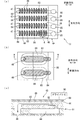
本発明の好適な実施形態に係るインクジェットプリンタ1の概略構成について説明する。図1に示すように、プリンタ1は、プラテン2、キャリッジ3、インクジェットヘッド5(以下、単にヘッド5とも称す)、ホルダ6、給紙ローラ7、排紙ローラ8、パージ装置9、フラッシング受け10、温度センサ160、タッチパネル161(図4参照)、及び制御装置100等を備えている。尚、以下では、図1の紙面手前側をプリンタ1の「上方」、紙面向こう側をプリンタ1の「下方」と定義する。また、図1に示す前後方向及び左右方向を、プリンタ1の「前後方向」及び「左右方向」と定義する。以下、前後、左右、上下の各方向語を適宜使用して説明する。 A schematic configuration of the inkjet printer 1 according to a preferred embodiment of the present invention will be described. As shown in FIG. 1, the printer 1 includes a platen 2, a carriage 3, an inkjet head 5 (hereinafter, also simply referred to as a head 5), a holder 6, a paper feed roller 7, a paper discharge roller 8, a purge device 9, and a flushing receiver 10. , A temperature sensor 160, a touch panel 161 (see FIG. 4), a control device 100, and the like. In the following, the front side of the paper surface of FIG. 1 is defined as "upper side" of the printer 1, and the other side of the paper surface is defined as "lower side" of the printer 1. Further, the front-back direction and the left-right direction shown in FIG. 1 are defined as the "front-back direction" and the "left-right direction" of the printer 1. Hereinafter, the front-back, left-right, and up-down directional words will be described as appropriate.

プラテン2の上面には、被記録媒体である用紙Pが載置される。また、プラテン2の上方には、左右方向(走査方向)に平行に延びる2本のガイドレール15,16が設けられる。 Paper P, which is a recording medium, is placed on the upper surface of the platen 2. Further, above the platen 2, two guide rails 15 and 16 extending in parallel in the left-right direction (scanning direction) are provided.

キャリッジ3は、2本のガイドレール15,16に取り付けられ、プラテン2と対向する領域において2本のガイドレール15,16に沿って左右方向に移動可能である。また、キャリッジ3には、駆動ベルト17が取り付けられている。駆動ベルト17は、2つのプーリ18,19に巻き掛けられた無端状のベルトである。一方のプーリ18はキャリッジ駆動モータ20(図4参照)に連結されている。キャリッジ駆動モータ20によってプーリ18が回転駆動されることで駆動ベルト17が走行し、これにより、キャリッジ3が左右方向に往復移動する。また、このとき、キャリッジ3上に搭載されたヘッド5は、このキャリッジ3とともに左右方向に往復移動することになる。 The carriage 3 is attached to the two guide rails 15 and 16 and can move in the left-right direction along the two guide rails 15 and 16 in the area facing the platen 2. A drive belt 17 is attached to the carriage 3. The drive belt 17 is an endless belt wound around two pulleys 18 and 19. One pulley 18 is connected to a carriage drive motor 20 (see FIG. 4). The drive belt 17 travels by rotationally driving the pulley 18 by the carriage drive motor 20, whereby the carriage 3 reciprocates in the left-right direction. Further, at this time, the head 5 mounted on the carriage 3 reciprocates in the left-right direction together with the carriage 3.

ホルダ6は、左右方向に並ぶ4つのカートリッジ装着部41を備えている。各カートリッジ装着部41には、インクカートリッジ42が着脱可能に装着される。4つのカートリッジ装着部41に装着される4つのインクカートリッジ42には、それぞれ、ブラック、イエロー、シアン、マゼンタのインクが貯溜されている。また、各カートリッジ装着部41は、図2に示すように、その内部に形成された内部流路41aと、内部流路41aの一端に接続された、筒状の樹脂針からなるニードル41bとを有している。カートリッジ装着部41にインクカートリッジ42が装着されたときに、インクカートリッジ42内のインクは、ニードル41b及び内部流路41aを経て、外部に供給される。尚、本実施形態では、各インクカートリッジ42に貯溜されるインクは、顔料インクである。 The holder 6 includes four cartridge mounting portions 41 arranged in the left-right direction. An ink cartridge 42 is detachably mounted on each cartridge mounting portion 41. Black, yellow, cyan, and magenta inks are stored in the four ink cartridges 42 mounted on the four cartridge mounting portions 41, respectively. Further, as shown in FIG. 2, each cartridge mounting portion 41 has an internal flow path 41a formed inside the cartridge mounting portion 41 and a needle 41b made of a cylindrical resin needle connected to one end of the internal flow path 41a. Have. When the ink cartridge 42 is mounted on the cartridge mounting portion 41, the ink in the ink cartridge 42 is supplied to the outside via the needle 41b and the internal flow path 41a. In the present embodiment, the ink stored in each ink cartridge 42 is a pigment ink.

図1に戻って、ヘッド5は、キャリッジ3に搭載されている。このヘッド5は、ヘッド本体13と、サブタンク14とを有する。サブタンク14にはチューブジョイント21が一体的に設けられている。そして、チューブジョイント21には、可撓性を有する4本の供給チューブ22それぞれの一端が着脱可能に接続されている。4本の供給チューブ22それぞれの他端は、ホルダ6の4つのカートリッジ装着部41の内部流路41a(図2参照)それぞれに接続されている。カートリッジ装着部41に装着された4つのインクカートリッジ42内のインクは、この4本の供給チューブ22を介して、サブタンク14に供給される。 Returning to FIG. 1, the head 5 is mounted on the carriage 3. The head 5 has a head body 13 and a sub tank 14. A tube joint 21 is integrally provided in the sub tank 14. One end of each of the four flexible supply tubes 22 is detachably connected to the tube joint 21. The other ends of each of the four supply tubes 22 are connected to the internal flow paths 41a (see FIG. 2) of the four cartridge mounting portions 41 of the holder 6. The ink in the four ink cartridges 42 mounted on the cartridge mounting portion 41 is supplied to the sub tank 14 via the four supply tubes 22.

ヘッド本体13は、サブタンク14の下部に取り付けられている。ヘッド本体13は、図3(a)に示すように、複数のノズル46及び複数のノズル46にそれぞれ連通する複数の圧力室83が形成された流路ユニット44と、流路ユニット44の上面に配置されたアクチュエータ45とを備えている。 The head body 13 is attached to the lower part of the sub tank 14. As shown in FIG. 3A, the head body 13 is formed on a flow path unit 44 in which a plurality of nozzles 46 and a plurality of pressure chambers 83 communicating with the plurality of nozzles 46 are formed, and on the upper surface of the flow path unit 44. It includes an arranged actuator 45.

図3(c)に示すように、流路ユニット44は4枚のプレートが積層された構造を有する。この流路ユニット44の下面には複数のノズル46が形成されている。図3(a)に示すように、複数のノズル46は前後方向(用紙Pの搬送方向)に配列されており、4色のインクにそれぞれ対応した、4列のノズル列47を構成している。4列のノズル列47からは、走査方向の右側に位置するノズル列47から順に、ブラック、イエロー、シアン、マゼンタのインクが吐出される。複数の圧力室83は、複数のノズル46と同様に4列に配列されている。 As shown in FIG. 3C, the flow path unit 44 has a structure in which four plates are laminated. A plurality of nozzles 46 are formed on the lower surface of the flow path unit 44. As shown in FIG. 3A, the plurality of nozzles 46 are arranged in the front-rear direction (the transport direction of the paper P), forming four rows of nozzle rows 47 corresponding to the four colors of ink, respectively. .. Black, yellow, cyan, and magenta inks are ejected from the four nozzle rows 47 in order from the nozzle row 47 located on the right side in the scanning direction. The plurality of pressure chambers 83 are arranged in four rows like the plurality of nozzles 46.

さらに、図3(a),(b)に示すように、流路ユニット44には、それぞれ前後方向に延在する4本のマニホールド84が形成されている。4本のマニホールド84は、4列の圧力室列に、4色のインクをそれぞれ供給する。また、4本のマニホールド84は、流路ユニット44の上面に形成された4つのインク供給孔85に接続されている。4つのインク供給孔85には、サブタンク14から4色のインクがそれぞれ供給される。また、マニホールド84から圧力室83へインクを供給する流路の途中には、流路抵抗が大きい絞り部82(図3(c)参照)が設けられている。以上の構成より、流路ユニット44内には、各マニホールド84から分岐して、絞り部82及び圧力室83を経てノズル46に至る個別流路が複数形成されている。 Further, as shown in FIGS. 3A and 3B, the flow path unit 44 is formed with four manifolds 84 extending in the front-rear direction, respectively. The four manifolds 84 supply four colors of ink to each of the four rows of pressure chambers. Further, the four manifolds 84 are connected to four ink supply holes 85 formed on the upper surface of the flow path unit 44. Four colors of ink are supplied from the sub tank 14 to the four ink supply holes 85, respectively. Further, a throttle portion 82 (see FIG. 3C) having a large flow path resistance is provided in the middle of the flow path for supplying ink from the manifold 84 to the pressure chamber 83. From the above configuration, a plurality of individual flow paths are formed in the flow path unit 44, branching from each manifold 84, passing through the throttle portion 82 and the pressure chamber 83, and reaching the nozzle 46.

図3(c)に示すように、アクチュエータ45は、複数の圧力室83を覆う振動板87と、この振動板87の上面に配置された圧電層88と、複数の圧力室83に対応した複数の個別電極89とを備えている。圧電層88の上面に位置する複数の個別電極89は、アクチュエータ45を駆動するドライバIC90とそれぞれ電気的に接続されている。 As shown in FIG. 3C, the actuator 45 includes a diaphragm 87 covering the plurality of pressure chambers 83, a piezoelectric layer 88 arranged on the upper surface of the diaphragm 87, and a plurality of actuators corresponding to the plurality of pressure chambers 83. The individual electrode 89 of the above is provided. The plurality of individual electrodes 89 located on the upper surface of the piezoelectric layer 88 are electrically connected to the driver IC 90 that drives the actuator 45, respectively.

圧電層88の下面に位置する振動板87は金属材料で形成されており、圧電層88を挟んで複数の個別電極89と対向する共通電極の役割を果たす。尚、この振動板87はドライバIC90のグランド線に接続されて常にグランド電位に保持される。 The diaphragm 87 located on the lower surface of the piezoelectric layer 88 is made of a metal material and serves as a common electrode facing a plurality of individual electrodes 89 with the piezoelectric layer 88 interposed therebetween. The diaphragm 87 is connected to the ground wire of the driver IC 90 and is always held at the ground potential.

以上の構成において、ドライバIC90から個別電極89に対して所定の駆動波形を有する駆動信号が、吐出周期の各々において入力されることにより、これに対応する圧電層88の容積が変形して圧力室83内のインクに圧力(吐出エネルギー)が付与され、ノズル46からインク滴が吐出される。なお、上述したようにマニホールド84と圧力室83との間には、絞り部82が設けられている。従って、この絞り部82により、圧力室83内で生じた圧力波がマニホールド84へ漏れることは抑制されている。 In the above configuration, when a drive signal having a predetermined drive waveform is input from the driver IC 90 to the individual electrodes 89 in each of the discharge cycles, the volume of the piezoelectric layer 88 corresponding to the drive signals is deformed and the pressure chamber is deformed. Pressure (ejection energy) is applied to the ink in 83, and ink droplets are ejected from the nozzle 46. As described above, a throttle portion 82 is provided between the manifold 84 and the pressure chamber 83. Therefore, the throttle portion 82 suppresses the leakage of the pressure wave generated in the pressure chamber 83 to the manifold 84.

図2に示すように、サブタンク14は、合成樹脂で成形された部材であり、水平面に沿って延在する板状の本体部分60と、この本体部分60の一端部から鉛直下方に延びてヘッド本体13に接続される連結部分61とを有する。サブタンク14には、ヘッド本体13のインク供給孔85にインクを供給する供給流路62が形成されている。なお、図2では、サブタンク14については、鉛直断面図として図示している一方で、ヘッド本体13については断面図とせず、側面図として図示している。 As shown in FIG. 2, the sub tank 14 is a member formed of a synthetic resin, and has a plate-shaped main body portion 60 extending along a horizontal plane and a head extending vertically downward from one end of the main body portion 60. It has a connecting portion 61 connected to the main body 13. The sub tank 14 is formed with a supply flow path 62 for supplying ink to the ink supply holes 85 of the head body 13. In FIG. 2, the sub tank 14 is shown as a vertical cross-sectional view, while the head body 13 is not shown as a cross-sectional view but as a side view.

本体部分60の上面には、供給チューブ22が接続可能なチューブジョイント21が取り付けられている。このチューブジョイント21に供給チューブ22が接続されることで、インクカートリッジ42に貯溜されたインクを供給流路62に供給することが可能となる。 A tube joint 21 to which the supply tube 22 can be connected is attached to the upper surface of the main body portion 60. By connecting the supply tube 22 to the tube joint 21, the ink stored in the ink cartridge 42 can be supplied to the supply flow path 62.

供給流路62は、本体部分60に形成された本体流路63と、連結部分61に形成された上下方向に延びる連結流路64とを有する。本体流路63は、水平面に沿って延在している。一方で、連結流路64は、本体流路63と接続される一端部(上端部)から鉛直下方に延在している。また、連結流路64は、下端においてヘッド本体13のインク供給孔85に接続されている。この連結流路64の上端部は、エアを一時的に貯溜可能なエア貯溜室65である。エア貯溜室65は、本体流路63の各位置と同じく、本体流路63及び連結流路64において最も上方となる位置である。このため、供給流路62に存在するエアを、ヘッド本体13に流れ込ませずに、このエア貯溜室65内に一時的に留めることができる。尚、以下では、説明の便宜上、図2に示すように、ニードル41bから複数のノズル46に至る流路全体をインク流路30と総称する。 The supply flow path 62 has a main body flow path 63 formed in the main body portion 60 and a connecting flow path 64 formed in the connecting portion 61 extending in the vertical direction. The main body flow path 63 extends along the horizontal plane. On the other hand, the connecting flow path 64 extends vertically downward from one end (upper end) connected to the main body flow path 63. Further, the connecting flow path 64 is connected to the ink supply hole 85 of the head body 13 at the lower end. The upper end of the connecting flow path 64 is an air storage chamber 65 capable of temporarily storing air. The air storage chamber 65 is the uppermost position in the main body flow path 63 and the connecting flow path 64, like each position of the main body flow path 63. Therefore, the air existing in the supply flow path 62 can be temporarily retained in the air storage chamber 65 without flowing into the head main body 13. In the following, for convenience of explanation, as shown in FIG. 2, the entire flow path from the needle 41b to the plurality of nozzles 46 is collectively referred to as an ink flow path 30.

また、本体部分60には、連結流路64に接続された排気流路(図示省略)も形成されている。この排気流路は、サブタンク14の右側面に設けられた排気部23(図1参照)まで延びている。排気部23の先端は開口となっている。また、排気部23の内部には、外部との連通/閉止を切り換える弁が設置されている。 Further, the main body portion 60 is also formed with an exhaust flow path (not shown) connected to the connecting flow path 64. This exhaust flow path extends to an exhaust portion 23 (see FIG. 1) provided on the right side surface of the sub tank 14. The tip of the exhaust unit 23 is an opening. Further, inside the exhaust unit 23, a valve for switching communication / closing with the outside is installed.

図1に戻って、給紙ローラ7と排紙ローラ8は、搬送モータ29(図4参照)によってそれぞれ同期して回転駆動される。給紙ローラ7と排紙ローラ8は協働して、プラテン2に載置された用紙Pを前方(搬送方向)に搬送する。 Returning to FIG. 1, the paper feed roller 7 and the paper discharge roller 8 are rotationally driven by the transfer motor 29 (see FIG. 4) in synchronization with each other. The paper feed roller 7 and the paper output roller 8 cooperate with each other to transport the paper P placed on the platen 2 forward (in the transport direction).

そして、プリンタ1は、給紙ローラ7と排紙ローラ8によって用紙Pを搬送方向に搬送させる搬送動作と、キャリッジ3とともにヘッド5を左右方向(走査方向)に移動させながらインクを吐出させる記録パス動作とを交互に繰り返し行うことにより、用紙Pに所望の画像等を印刷する。即ち、本実施形態のプリンタ1は、シリアル式のインクジェットプリンタである。 Then, the printer 1 has a transport operation of transporting the paper P in the transport direction by the paper feed roller 7 and the paper discharge roller 8, and a recording path for ejecting ink while moving the head 5 in the left-right direction (scanning direction) together with the carriage 3. By repeating the operation alternately, a desired image or the like is printed on the paper P. That is, the printer 1 of this embodiment is a serial type inkjet printer.

フラッシング受け10は、プラテン2よりも左側に配置されている。キャリッジ3を移動させてヘッド5をフラッシング位置に位置付けさせたとき、複数のノズル46が、フラッシング受け10と上下に対向する。そして、プリンタ1では、ヘッド5をフラッシング位置に位置付けさせた状態で、ヘッド5のアクチュエータ45を駆動して、ノズル46からフラッシング受け10に向けて増粘したインク等を吐出して排出させるフラッシングを行わせることができる。 The flushing receiver 10 is arranged on the left side of the platen 2. When the carriage 3 is moved to position the head 5 at the flushing position, the plurality of nozzles 46 face the flushing receiver 10 in the vertical direction. Then, in the printer 1, with the head 5 positioned at the flushing position, the actuator 45 of the head 5 is driven to eject the thickened ink or the like from the nozzle 46 toward the flushing receiver 10 to discharge the flushing. Can be done.

パージ装置9は、ヘッド5のノズル46の吐出性の低下の抑制や、吐出性の回復のためのメンテナンス動作を行うためのものであり、キャップユニット50、吸引ポンプ51、切換装置52、及び廃液タンク53等を備えている。 The purge device 9 is for suppressing a decrease in the discharge property of the nozzle 46 of the head 5 and performing a maintenance operation for recovering the discharge property, and is a cap unit 50, a suction pump 51, a switching device 52, and a waste liquid. It is equipped with a tank 53 and the like.

キャップユニット50は、プラテン2よりも右側に配置されている。キャリッジ3がプラテン2よりも右側に移動したときにはこのキャップユニット50と上下に対向する。また、キャップユニット50は、キャップ昇降モータ54(図4参照)により駆動されて、上下方向に昇降可能である。このキャップユニット50は、ヘッド5に接触して装着可能な、キャップ55を備えている。キャップ55は、例えばゴム材料によって構成されており、ノズルキャップ55a及び排気キャップ55bを備えている。 The cap unit 50 is arranged on the right side of the platen 2. When the carriage 3 moves to the right of the platen 2, it faces the cap unit 50 vertically. Further, the cap unit 50 is driven by a cap elevating motor 54 (see FIG. 4) and can be elevated and lowered in the vertical direction. The cap unit 50 includes a cap 55 that can be attached in contact with the head 5. The cap 55 is made of, for example, a rubber material, and includes a nozzle cap 55a and an exhaust cap 55b.

ヘッド5がキャップユニット50と対向した状態では、ノズルキャップ55aがヘッド本体13の下面と対向し、排気キャップ55bがサブタンク14の排気部23の下面と対向する。この状態で、ヘッド5から下方に離間した離間位置に位置しているキャップユニット50を、キャップ昇降モータ54により、離間位置よりも上方のキャッピング位置まで上昇させると、キャップユニット50がヘッド5に装着される。このとき、ノズルキャップ55aにより、4列のノズル列47に属する全てのノズル46が共通に覆われるとともに、排気キャップ55bが排気部23に接続される。排気キャップ55bには、排気部23内の弁をそれぞれ開閉する棒状の開閉部材27が取り付けられている。排気キャップ55bが排気部23に接続された状態で、棒状の開閉部材27が、排気モータ28(図4参照)によって上下に駆動されて、下方から排気部23内に挿入されることによって内部の弁を駆動する。 When the head 5 faces the cap unit 50, the nozzle cap 55a faces the lower surface of the head body 13, and the exhaust cap 55b faces the lower surface of the exhaust portion 23 of the sub tank 14. In this state, when the cap unit 50 located at a separated position downward from the head 5 is raised to a capping position above the separated position by the cap elevating motor 54, the cap unit 50 is attached to the head 5. Will be done. At this time, the nozzle caps 55a commonly cover all the nozzles 46 belonging to the four rows of nozzle rows 47, and the exhaust caps 55b are connected to the exhaust unit 23. A rod-shaped opening / closing member 27 for opening / closing a valve in the exhaust portion 23 is attached to the exhaust cap 55b. With the exhaust cap 55b connected to the exhaust unit 23, the rod-shaped opening / closing member 27 is driven up and down by the exhaust motor 28 (see FIG. 4) and inserted into the exhaust unit 23 from below. Drive the valve.

ノズルキャップ55a及び排気キャップ55bは、切換装置52を介して吸引ポンプ51に接続されている。この吸引ポンプ51は、ロータリーポンプである。切換装置52は、吸引ポンプ51の連通先を、ノズルキャップ55aと、排気キャップ55bとの間で選択的に切り換える。この切換装置52の連通先を切り換えることにより、4列のノズル列47に属する全てのノズル46からインクを強制的に排出させる吸引パージと、サブタンク14のエア貯溜室65内のエアを排気する排気パージとを、選択的に実行できる。 The nozzle cap 55a and the exhaust cap 55b are connected to the suction pump 51 via the switching device 52. The suction pump 51 is a rotary pump. The switching device 52 selectively switches the communication destination of the suction pump 51 between the nozzle cap 55a and the exhaust cap 55b. By switching the communication destination of the switching device 52, a suction purge for forcibly discharging ink from all the nozzles 46 belonging to the nozzle rows 47 in the four rows and an exhaust for exhausting the air in the air storage chamber 65 of the sub tank 14 Purge can be performed selectively.

吸引パージでは、まず、ノズルキャップ55aがヘッド本体13に装着されて複数のノズル46を覆った状態で、切換装置52により吸引ポンプ51をノズルキャップ55aに連通させる。この状態で吸引ポンプ51を駆動し、ノズルキャップ55a内を負圧(吸引)することで、ヘッド本体13の複数のノズル46からそれぞれインクを吸引して排出させる。これにより、インク流路30内の高粘度化したインクがノズル46から排出されて、ノズル46の吐出性の回復等を行うことができる。 In the suction purge, first, the suction pump 51 is communicated with the nozzle cap 55a by the switching device 52 in a state where the nozzle cap 55a is attached to the head body 13 and covers the plurality of nozzles 46. By driving the suction pump 51 in this state and applying negative pressure (suction) inside the nozzle cap 55a, ink is sucked and discharged from each of the plurality of nozzles 46 of the head body 13. As a result, the highly viscous ink in the ink flow path 30 is discharged from the nozzle 46, and the ejection property of the nozzle 46 can be restored.

排気パージでは、排気キャップ55bが排気部23に接続され、且つ、開閉部材27により排気部23内の弁が開放された状態で、切換装置52により吸引ポンプ51を排気キャップ55bに連通させる。この状態で吸引ポンプ51を駆動し、排気部23に負圧を作用させる。これにより、サブタンク14のエア貯溜室65内のエアを、ヘッド本体13に流れ込む前に排気キャップ55bに排気することができ、その結果として、ノズル46の吐出性が悪化することを抑制することができる。吸引パージや排気パージによって、ヘッド5から排出されたインクは、吸引ポンプ51に接続された廃液タンク53に送られる。 In the exhaust purge, the suction pump 51 is communicated with the exhaust cap 55b by the switching device 52 in a state where the exhaust cap 55b is connected to the exhaust unit 23 and the valve in the exhaust unit 23 is opened by the opening / closing member 27. In this state, the suction pump 51 is driven to apply a negative pressure to the exhaust unit 23. As a result, the air in the air storage chamber 65 of the sub tank 14 can be exhausted to the exhaust cap 55b before flowing into the head body 13, and as a result, it is possible to suppress deterioration of the ejection property of the nozzle 46. can. The ink discharged from the head 5 by the suction purge or the exhaust purge is sent to the waste liquid tank 53 connected to the suction pump 51.

温度センサ160は、ホルダ6近傍に配置されており、周囲温度を計測する。タッチパネル161は、ユーザからの各種操作入力の受け付けや、各種の設定画面や動作状態等をユーザに対して表示することが可能なユーザインターフェースである。 The temperature sensor 160 is arranged near the holder 6 and measures the ambient temperature. The touch panel 161 is a user interface capable of accepting various operation inputs from the user and displaying various setting screens, operating states, and the like to the user.

制御装置100は、図4に示すように、CPU(Central Processing Unit)101、ROM(Read Only Memory)102、RAM(Random Access Memory)103、不揮発性メモリ104、ASIC(Application Specific Integrated Circuit)105等を含む。ROM102には、CPU101が実行するプログラム、各種固定データ等が記憶されている。RAM103には、プログラム実行時に必要なデータ(印刷データ等)が一時的に記憶される。不揮発性メモリ104には、後述する総供給量カウント情報121等が記憶される。ASIC105には、ヘッド5、キャリッジ駆動モータ20等、プリンタ1の様々な装置あるいは駆動部と接続されている。また、ASIC105は、通信インターフェース110を介してPC等の外部装置200と接続されている。 As shown in FIG. 4, the control device 100 includes a CPU (Central Processing Unit) 101, a ROM (Read Only Memory) 102, a RAM (Random Access Memory) 103, a non-volatile memory 104, an ASIC (Application Specific Integrated Circuit) 105, and the like. including. The ROM 102 stores a program executed by the CPU 101, various fixed data, and the like. Data (print data, etc.) required for program execution is temporarily stored in the RAM 103. The non-volatile memory 104 stores total supply amount count information 121 and the like, which will be described later. The ASIC 105 is connected to various devices or drive units of the printer 1, such as a head 5 and a carriage drive motor 20. Further, the ASIC 105 is connected to an external device 200 such as a PC via the communication interface 110.

尚、以下の説明では、制御装置100が行う各種処理は、CPU101が行うものとして説明するが、CPUと、ASICとの協動で行ってもよい。また、制御装置100が複数のCPUを備え、複数のCPUによって処理を分担して行ってもよい。また、制御装置100が複数のASICを備え、複数のASICによって処理を分担してもよい。あるいは、1つのASIC単独で処理を行ってもよい。 In the following description, various processes performed by the control device 100 will be described as being performed by the CPU 101, but they may be performed in cooperation with the CPU and the ASIC. Further, the control device 100 may include a plurality of CPUs, and the processing may be shared by the plurality of CPUs. Further, the control device 100 may include a plurality of ASICs, and the processing may be shared by the plurality of ASICs. Alternatively, the processing may be performed by one ASIC alone.

CPU101は、外部装置200から受信した印刷指示に基づいて、ヘッド5やキャリッジ駆動モータ20等を制御して、用紙Pに画像等を印刷する印刷処理を実行する。また、CPU101は、パージ装置9に吸引パージを行なわせたり、ヘッド5のアクチュエータ45にフラッシングを行なわせたりして、ヘッド5のノズル46からインクを排出させる排出処理を実行する。 The CPU 101 controls the head 5, the carriage drive motor 20, and the like based on the print instruction received from the external device 200, and executes a printing process for printing an image or the like on the paper P. Further, the CPU 101 executes a discharge process of ejecting ink from the nozzle 46 of the head 5 by causing the purge device 9 to perform suction purging or the actuator 45 of the head 5 to perform flushing.

ここで、本実施形態では、上記排出処理として、大きく分類して、印刷前フラッシング処理、印刷前パージ処理、沈降排出パージ処理、ユーザパージ処理、及び定期パージ処理の5種類がある。以下、これらの排出処理について説明する。尚、以下では、説明の便宜上、4色のインクのうちの1色のインクに関連した排出処理について焦点を当てて説明する。 Here, in the present embodiment, the discharge treatment is roughly classified into five types: pre-print flushing treatment, pre-print purge treatment, sedimentation discharge purge treatment, user purge treatment, and periodic purge treatment. Hereinafter, these discharge treatments will be described. In the following, for convenience of explanation, the discharge treatment related to one of the four color inks will be described with a focus.

印刷前フラッシング処理は、外部装置200から印刷指令を受信した後の、印刷処理を実行する直前に、アクチュエータ45に上記フラッシングを行わせる排出処理である。印刷処理を実行する直前に印刷前フラッシング処理を実行することで、印刷処理の開始時においてノズル46の吐出性を良好な状態にすることができる。その結果として、印刷処理により用紙Pに印刷される画像の品質を向上させることができる。 The pre-print flushing process is a discharge process in which the actuator 45 is made to perform the flushing after receiving a print command from the external device 200 and immediately before executing the print process. By executing the pre-print flushing process immediately before executing the print process, the ejection property of the nozzle 46 can be made good at the start of the print process. As a result, the quality of the image printed on the paper P by the printing process can be improved.

印刷前パージ処理は、外部装置200から印刷指令を受信した後、印刷処理を実行する前に、パージ装置9に吸引パージを行なわせる排出処理である。この印刷前パージ処理は、ノズル46内のインクの粘度が高いこと等を理由により、上記印刷前フラッシング処理だけでは、ヘッド5内の増粘したインクを排出させることができないときに実行される。つまり、ノズル46内のインクの粘度が所定の閾値(以下、第1閾値)以上のときに、印刷前パージ処理は実行される。この印刷前パージ処理を実行することで、ノズル46の吐出性をより確実に回復することができ、その結果として、印刷処理により用紙Pに印刷される画像の品質を向上させることができる。なお、印刷前パージ処理を実行した後、印刷処理を開始するまでには、キャップユニット50をキャッピング位置から離間位置に下降させる等の処理が必要である。このため、印刷前パージ処理を実行したとしても印刷処理の開始時までの期間、ノズル46内のインクが乾燥により増粘する。従って、本実施形態では、CPU101は、印刷前パージ処理を実行した場合でも、印刷処理を実行する直前に、上記印刷前フラッシング処理を実行するように構成されている。 The pre-print purge process is a discharge process in which the purge device 9 is made to perform suction purge after receiving a print command from the external device 200 and before executing the print process. This pre-printing purge process is executed when the thickened ink in the head 5 cannot be discharged only by the pre-printing flushing process due to the high viscosity of the ink in the nozzle 46 and the like. That is, when the viscosity of the ink in the nozzle 46 is equal to or higher than a predetermined threshold value (hereinafter referred to as the first threshold value), the pre-printing purge process is executed. By executing this pre-printing purge process, the ejection property of the nozzle 46 can be more reliably restored, and as a result, the quality of the image printed on the paper P by the printing process can be improved. After executing the pre-printing purge process, it is necessary to lower the cap unit 50 from the capping position to the separated position before starting the printing process. Therefore, even if the pre-printing purge process is executed, the ink in the nozzle 46 is thickened by drying during the period until the start of the printing process. Therefore, in the present embodiment, the CPU 101 is configured to execute the pre-print flushing process immediately before executing the print process even when the pre-print purge process is executed.

次に、沈降排出パージ処理を説明するに先立って、前提となる事項について説明する。上述したように、インクカートリッジ42に貯溜されているインクは顔料インクである。顔料インクは、顔料が溶媒中に分散された状態で存在しており、長時間静置状態にあると比重の大きい顔料がインクカートリッジ42の底部に沈降する。このため、インクカートリッジ42内においては、長時間静置状態にあると、インクカートリッジ42の底部に顔料が多量に沈降する。その結果として、インクカートリッジ42の底部において顔料インクの顔料濃度が局所的に高くなり、その粘度も局所的に非常に高くなる。このように顔料の沈降により高粘度化した顔料インクがノズル46内に供給されると、上記印刷前パージ処理を実行したとしても、ノズル46の吐出性を回復することができない。そこで、CPU101は、外部装置200から印刷指令を受信した際において、顔料の沈降に起因してノズル46内の顔料インクの粘度が上記第1閾値よりも大きい第2閾値以上であるときには、沈降排出パージ処理を印刷前パージ処理の代わりに実行する。この沈降排出パージ処理は、顔料の沈降に起因して増粘した顔料インクを確実に排出するために、印刷前パージ処理と比べて、排出するインクの排出量が多くなるように、吸引ポンプ51の駆動条件が設定されている。例えば、沈降排出パージ処理では、印刷前パージ処理と比べて、吸引ポンプ51の回転時間が長くなるように設定されている。この沈降排出パージ処理を実行することにより、ノズル46の吐出性をより確実に回復することができる。 Next, before explaining the sedimentation discharge purge process, the premise items will be described. As described above, the ink stored in the ink cartridge 42 is a pigment ink. The pigment ink exists in a state in which the pigment is dispersed in a solvent, and when the pigment is left in a standing state for a long time, a pigment having a large specific density is settled on the bottom of the ink cartridge 42. Therefore, in the ink cartridge 42, if the ink cartridge 42 is left to stand for a long time, a large amount of pigment will settle on the bottom of the ink cartridge 42. As a result, the pigment concentration of the pigment ink is locally increased at the bottom of the ink cartridge 42, and the viscosity thereof is also locally increased. When the pigment ink having a high viscosity due to the precipitation of the pigment is supplied into the nozzle 46, the ejection property of the nozzle 46 cannot be restored even if the pre-printing purge treatment is executed. Therefore, when the CPU 101 receives a print command from the external device 200 and the viscosity of the pigment ink in the nozzle 46 is greater than or equal to the second threshold value due to the sedimentation of the pigment, the CPU 101 sediments and discharges. Perform the purge process instead of the pre-print purge process. In this sedimentation discharge purge treatment, in order to reliably discharge the pigment ink thickened due to the sedimentation of the pigment, the suction pump 51 so as to discharge a large amount of the discharged ink as compared with the pre-printing purge treatment. Driving conditions are set. For example, in the sedimentation / discharge purge process, the rotation time of the suction pump 51 is set to be longer than that in the pre-print purge process. By executing this sedimentation discharge purge process, the discharge property of the nozzle 46 can be recovered more reliably.

ユーザパージ処理は、タッチパネル161を介したユーザによる操作入力に応じて、パージ装置9に吸引パージを行なわせる排出処理である。例えば、CPU101は、タッチパネル161を介したユーザによる操作入力や外部装置200から受信した印刷指令に基づき、ヘッド5やキャリッジ駆動モータ20等を制御して、不吐出ノズルチェック用(ノズル抜けチェック用)のテストパターンを用紙Pに印刷する。その後、CPU101は、タッチパネル161を介して、そのテストパターンの印刷結果に対するユーザの評価を受け付ける。そして、CPU101は、そのユーザの評価が、不吐出ノズルの数が所定数以上であることを示す評価である場合には、当該評価をユーザパージの実行指令として、ユーザパージ処理を実行する。なお、本実施形態では、このユーザパージ処理は、印刷前パージ処理と比べて、吸引ポンプ51の回転速度が速く、且つ吸引ポンプ51の回転時間も長い吸引パージをパージ装置9に行わせる。このユーザパージ処理を実行することにより、ノズル46の吐出性を確実に回復することができる。 The user purge process is a discharge process in which the purge device 9 performs suction purge in response to an operation input by the user via the touch panel 161. For example, the CPU 101 controls the head 5 and the carriage drive motor 20 based on an operation input by the user via the touch panel 161 and a print command received from the external device 200 to check for non-ejection nozzles (for checking for missing nozzles). The test pattern of is printed on paper P. After that, the CPU 101 receives the user's evaluation of the print result of the test pattern via the touch panel 161. Then, when the user's evaluation is an evaluation indicating that the number of non-ejection nozzles is a predetermined number or more, the CPU 101 executes the user purge process with the evaluation as a user purge execution command. In the present embodiment, in this user purge process, the purge device 9 is made to perform a suction purge in which the rotation speed of the suction pump 51 is faster and the rotation time of the suction pump 51 is longer than that in the pre-printing purge process. By executing this user purge process, the ejection property of the nozzle 46 can be reliably restored.

定期パージ処理は、所定期間経過する毎(本実施形態では1か月経過する毎)に、パージ装置9に吸引パージを行なわせる排出処理である。ここで、ノズル46から長期間インクが吐出されなかった場合、ノズル46内のインクは乾燥により増粘する。このように長期間インクが吐出されない場合でも、印刷処理の前に、印刷前フラッシング処理や印刷前パージ処理を実行することでノズル46の吐出性を回復させることは可能である。しかしながら、ノズル46内のインクが乾燥により非常に高粘度になると、印刷前フラッシング処理や印刷前パージ処理において、ノズル46の吐出性を回復させるためには、ノズル46から非常に多くのインクを排出する必要がある。そこで、CPU101は、1か月経過する毎に定期パージ処理を実行して、ノズル46の吐出性が低下することを定期的に抑制する。これにより、ノズル46内のインクが乾燥により非常に高粘度になることを抑制することができ、定期パージ処理を行なわない構成と比べて、インクの総消費量を抑えることができる。 The periodic purge process is a discharge process in which the purge device 9 performs suction purging every time a predetermined period elapses (every one month elapses in this embodiment). Here, when the ink is not ejected from the nozzle 46 for a long period of time, the ink in the nozzle 46 becomes thickened by drying. Even if the ink is not ejected for a long period of time as described above, it is possible to restore the ejection property of the nozzle 46 by executing the pre-print flushing process or the pre-print purge process before the printing process. However, when the ink in the nozzle 46 becomes extremely viscous due to drying, a large amount of ink is discharged from the nozzle 46 in order to restore the ejection property of the nozzle 46 in the pre-print flushing process and the pre-print purge process. There is a need to. Therefore, the CPU 101 executes a periodic purge process every one month to periodically suppress the deterioration of the ejection property of the nozzle 46. As a result, it is possible to prevent the ink in the nozzle 46 from becoming extremely viscous due to drying, and it is possible to suppress the total consumption of ink as compared with a configuration in which the periodic purge treatment is not performed.

また、本実施形態では、定期パージ処理において、供給チューブ22内に存在するエアAをサブタンク14のエア貯溜室65に移動させることも目的としている。以下、具体的に説明する。供給チューブ22内には、インク中に含まれる微少のエアや、供給チューブ22内のインクが経時により水分が蒸発することで生成されるエア、インクカートリッジ42をカートリッジ装着部41に装着した際にニードル41bから流入した噛み込みエア等が存在する。これらの供給チューブ22内のエアAは、印刷処理や排出処理によりノズル46からインクが吐出又は排出されると、次第にエア貯溜室65側に移動する。そして、このエアAは、エア貯溜室65側に到達したときに実行される上記排気パージにより、インクと共に外部に排出されることになる。 Further, in the present embodiment, it is also an object of the periodic purge process to move the air A existing in the supply tube 22 to the air storage chamber 65 of the sub tank 14. Hereinafter, a specific description will be given. When a minute amount of air contained in the ink, air generated by evaporation of water from the ink in the supply tube 22 over time, and an ink cartridge 42 are mounted on the cartridge mounting portion 41 in the supply tube 22. There is biting air or the like that has flowed in from the needle 41b. The air A in these supply tubes 22 gradually moves to the air storage chamber 65 side when ink is ejected or ejected from the nozzle 46 by the printing process or the ejection process. Then, the air A is discharged to the outside together with the ink by the exhaust purge executed when the air A reaches the air storage chamber 65 side.

ところで、供給チューブ22は、サブタンク14等とは異なり、気体透過性が高い(ガスバリア性が低い)流路部材である。このため、供給チューブ22内のエアAは、供給チューブ22の外壁を介して大気が浸透することで時間の経過とともに成長する。従って、エアAが供給チューブ22内に長時間滞在していた場合には、エア貯溜室65に到達したときのエアAの体積が非常に大きくなる。その結果として、排気パージによりこのエアAを排出しようとすると、排出量を多くする必要があり、その際に排出されるインクの排出量が増えるなどの問題が生じる。 By the way, unlike the sub tank 14 and the like, the supply tube 22 is a flow path member having high gas permeability (low gas barrier property). Therefore, the air A in the supply tube 22 grows with the passage of time as the atmosphere permeates through the outer wall of the supply tube 22. Therefore, when the air A stays in the supply tube 22 for a long time, the volume of the air A when it reaches the air storage chamber 65 becomes very large. As a result, when the air A is to be discharged by the exhaust purge, it is necessary to increase the discharge amount, which causes problems such as an increase in the discharge amount of the ink discharged at that time.

そこで、本実施形態では、定期パージ処理により排出するインクの排出量は、エアAが供給チューブ22内に滞在する時間を短くすべく、以下のように設定されている。即ち、供給チューブ22内の各種エアがエア貯溜室65に到達したときの体積が、当該エア貯溜室65の容量未満となるように、各定期パージ処理により排出するインクの排出量が設定されている。例えば、上記噛み込みエアは、供給チューブ22内に流入時の体積が他のエアと比べて高く、また、その体積は実験等により予め推定することができる。従って、この噛み込みエアが供給チューブ22内に流入した後、定期パージ処理のみにより供給チューブ22内を移動してエア貯溜室65に到達した際の、当該噛み込みエアの体積がエア貯溜室65の容量未満となるよう、各定期パージ処理におけるインクの排出量が設定される。このように各定期パージ処理のインクの排出量を設定することで、排気パージにより排出されるインクの排出量が増加することを抑制することができる。 Therefore, in the present embodiment, the amount of ink discharged by the periodic purge process is set as follows in order to shorten the time that the air A stays in the supply tube 22. That is, the amount of ink discharged by each periodic purge process is set so that the volume when various types of air in the supply tube 22 reach the air storage chamber 65 is less than the capacity of the air storage chamber 65. There is. For example, the volume of the bitten air when flowing into the supply tube 22 is higher than that of other air, and the volume can be estimated in advance by experiments or the like. Therefore, after the biting air has flowed into the supply tube 22, the volume of the biting air when the biting air moves in the supply tube 22 and reaches the air storage chamber 65 only by the periodic purge process is the air storage chamber 65. The amount of ink discharged in each periodic purge process is set so as to be less than the capacity of. By setting the ink discharge amount of each periodic purge process in this way, it is possible to suppress an increase in the ink discharge amount discharged by the exhaust purge.

以上説明した各排出処理それぞれにおいて、ノズル46の吐出性を回復させるためには、ノズル46内のインクの粘度に応じて排出条件を変更する必要がある。例えば、ノズル46内のインクの粘度が高いほど、排出処理において排出するインクの排出量が多くなるように排出条件を変更する必要がある。従って、ノズル46内のインクの粘度を精度よく推定する必要がある。尚、排出条件とは、パージ装置9にパージを行なわせる排出処理の場合には、吸引ポンプ51の回転時間、回転速度、トルク等の吸引ポンプ51の駆動条件である。一方で、アクチュエータ45にフラッシングを行わせる排出処理の場合には、排出条件は、個別電極89に対して出力する駆動信号の駆動波形の形状や、個別電極89に対して出力する駆動信号の数(フラッシング発数)等のアクチュエータ45の駆動条件である。 In each of the ejection processes described above, in order to restore the ejection property of the nozzle 46, it is necessary to change the ejection conditions according to the viscosity of the ink in the nozzle 46. For example, it is necessary to change the discharge conditions so that the higher the viscosity of the ink in the nozzle 46, the larger the amount of ink discharged in the discharge process. Therefore, it is necessary to accurately estimate the viscosity of the ink in the nozzle 46. The discharge condition is a drive condition of the suction pump 51 such as the rotation time, the rotation speed, and the torque of the suction pump 51 in the case of the discharge process in which the purge device 9 performs purging. On the other hand, in the case of the discharge process in which the actuator 45 is flushed, the discharge conditions are the shape of the drive waveform of the drive signal output to the individual electrode 89 and the number of drive signals output to the individual electrode 89. It is a driving condition of the actuator 45 such as (number of flushing occurrences).

そこで、CPU101は、ノズル46内のインクの粘度を推定する以下のノズル内粘度推定処理を実行する。このノズル内粘度推定処理では、所定期間経過する毎(本実施形態では、1か月毎)に、インクカートリッジ42から供給されるインクの粘度を推定するカートリッジ内粘度推定処理を実行し、このカートリッジ内粘度推定処理の推定結果を用いてノズル46内のインクの粘度を推定する。以下、まず、カートリッジ内粘度推定処理について詳細に説明する。 Therefore, the CPU 101 executes the following in-nozzle viscosity estimation process for estimating the viscosity of the ink in the nozzle 46. In this in-nozzle viscosity estimation process, an in-cartridge viscosity estimation process for estimating the viscosity of the ink supplied from the ink cartridge 42 is executed every time a predetermined period elapses (in this embodiment, every month), and this cartridge is used. The viscosity of the ink in the nozzle 46 is estimated using the estimation result of the internal viscosity estimation process. Hereinafter, first, the viscosity estimation process in the cartridge will be described in detail.

上述したように、インクカートリッジ42内では、長時間静置状態にあると、インクカートリッジ42の底部に顔料が多量に沈降する。その結果として、インクカートリッジ42の底部において顔料インクの顔料濃度が局所的に高くなり、その粘度も局所的に高くなる。このため、インクカートリッジ42から供給されるインクの粘度は常に一定とはならず、変化する。カートリッジ内粘度推定処理では、このインクカートリッジ42から供給されるインクの粘度を推定する。 As described above, in the ink cartridge 42, if the ink cartridge 42 is left to stand for a long time, a large amount of pigment will settle on the bottom of the ink cartridge 42. As a result, the pigment concentration of the pigment ink is locally increased at the bottom of the ink cartridge 42, and the viscosity thereof is also locally increased. Therefore, the viscosity of the ink supplied from the ink cartridge 42 is not always constant but changes. In the in-cartridge viscosity estimation process, the viscosity of the ink supplied from the ink cartridge 42 is estimated.

ここで、インクカートリッジ42内に沈降する顔料の沈降量は、当該インクカートリッジ42が静置状態に置かれていた期間が長いほど多くなる。また、インクカートリッジ42内に沈降する顔料の沈降量は、インクカートリッジ42内からのインクの供給頻度が少ないほど多くなる。加えて、顔料インクは、インクカートリッジ42内の温度が高いほど、粘度が低くなるため、顔料の沈降が促進される。 Here, the amount of pigment settling in the ink cartridge 42 increases as the period in which the ink cartridge 42 is left in a stationary state increases. Further, the amount of pigment settling in the ink cartridge 42 increases as the frequency of ink supply from the ink cartridge 42 decreases. In addition, the higher the temperature in the ink cartridge 42, the lower the viscosity of the pigment ink, so that the precipitation of the pigment is promoted.

そこで、不揮発性メモリ104には、図4に示すように、総供給量カウント情報121、経過時間情報122、及び温度履歴情報123を有している。 Therefore, as shown in FIG. 4, the non-volatile memory 104 has total supply amount count information 121, elapsed time information 122, and temperature history information 123.

総供給量カウント情報121は、インクカートリッジ42がカートリッジ装着部41に装着された装着時点からの、インクカートリッジ42内から供給されたインクの総供給量を示すカウント情報である。CPU101は、印刷処理、及び排出処理等を実行することにより、インクカートリッジ42内からインクが供給される毎に、その供給量を算出して、総供給量カウント情報121のカウント値に加算する。なお、印刷処理やフラッシングの際にヘッド5のノズル46から吐出されるインクの吐出量については、アクチュエータ45の駆動態様等により算出することは可能である。また、吸引パージの際に、ノズル46から排出されるインクの排出量については、吸引ポンプ51の回転速度や回転時間などの駆動条件から算出することができる。 The total supply amount count information 121 is count information indicating the total supply amount of ink supplied from the ink cartridge 42 from the time when the ink cartridge 42 is mounted on the cartridge mounting portion 41. The CPU 101 calculates the supply amount each time ink is supplied from the ink cartridge 42 by executing the printing process, the ejection process, and the like, and adds the ink to the count value of the total supply amount count information 121. The amount of ink ejected from the nozzle 46 of the head 5 during the printing process or flushing can be calculated from the driving mode of the actuator 45 or the like. Further, the amount of ink discharged from the nozzle 46 during suction purging can be calculated from driving conditions such as the rotation speed and rotation time of the suction pump 51.

経過時間情報122は、上記装着時点からの経過時間を示す情報であり、装着時点以降において、制御装置100の内部時計により逐次更新される。温度履歴情報123は、上記装着時点から温度センサ160により計測された温度の履歴情報である。CPU101は、内部時計により一定時間を計時する毎に、そのときに温度センサ160により計測されていた温度を温度履歴情報123に追加する。 The elapsed time information 122 is information indicating the elapsed time from the time of wearing, and is sequentially updated by the internal clock of the control device 100 after the time of wearing. The temperature history information 123 is the history information of the temperature measured by the temperature sensor 160 from the time of mounting. Every time the CPU 101 measures a certain time by the internal clock, the CPU 101 adds the temperature measured by the temperature sensor 160 to the temperature history information 123.

CPU101は、カートリッジ内粘度推定処理では、これら総供給量カウント情報121、経過時間情報122、及び温度履歴情報123に基づいて、顔料の沈降量に関する沈降情報を推定して取得し、この沈降情報に基づいて、インクカートリッジ42から供給されるインクの粘度を推定する。このカートリッジ内粘度推定処理により推定したインクの粘度は、総供給量カウント情報121のカウント値と関連付けられてカートリッジ内粘度情報として、不揮発性メモリ104のカートリッジ内粘度テーブル124に記憶される。カートリッジ内粘度テーブル124には、このカートリッジ内粘度情報の履歴が記憶されている。以下、このカートリッジ内粘度推定処理に関するインクジェットプリンタの処理動作について、図5を参照しつつ説明する。 In the in-cartridge viscosity estimation process, the CPU 101 estimates and acquires sedimentation information regarding the sedimentation amount of the pigment based on the total supply amount count information 121, elapsed time information 122, and temperature history information 123, and uses this sedimentation information as the sedimentation information. Based on this, the viscosity of the ink supplied from the ink cartridge 42 is estimated. The ink viscosity estimated by this in-cartridge viscosity estimation process is stored in the in-cartridge viscosity table 124 of the non-volatile memory 104 as the in-cartridge viscosity information in association with the count value of the total supply amount count information 121. The history of the viscosity information in the cartridge is stored in the viscosity table 124 in the cartridge. Hereinafter, the processing operation of the inkjet printer related to the viscosity estimation process in the cartridge will be described with reference to FIG.

CPU101は、まず、カートリッジ内粘度推定処理の前回実行時点から1か月経過したか否かを判断する(A1)。そして、前回実行時点から1か月経過したと判断した場合(A1:YES)には、総供給量カウント情報121、経過時間情報122、及び温度履歴情報123に基づいて、インクカートリッジ42から供給されるインクの粘度を推定するカートリッジ内粘度推定処理を実行する(A2)。そして、CPU101は、この推定したインクの粘度と、総供給量カウント情報121の現在のカウント値とを関連付けてカートリッジ内粘度情報として、カートリッジ内粘度テーブル124に記憶する(A3)。このA3の処理が終了すると、A1の処理に戻る。 First, the CPU 101 determines whether or not one month has passed from the time of the previous execution of the viscosity estimation process in the cartridge (A1). When it is determined that one month has passed since the previous execution (A1: YES), the ink is supplied from the ink cartridge 42 based on the total supply amount count information 121, the elapsed time information 122, and the temperature history information 123. The in-cartridge viscosity estimation process for estimating the viscosity of the ink is executed (A2). Then, the CPU 101 associates the estimated viscosity of the ink with the current count value of the total supply amount count information 121 and stores it in the cartridge internal viscosity table 124 as the cartridge internal viscosity information (A3). When the processing of A3 is completed, the process returns to the processing of A1.

以上により、カートリッジ内粘度テーブル124には、インクカートリッジ42から供給されるインクの推定粘度が、総供給量カウント情報121のカウント値と関連付けられて記憶されることになる。ノズル内粘度推定処理では、このカートリッジ内粘度テーブル124と、総供給量カウント情報121の現在のカウント値に基づいて、現在、ノズル46内にあるインクが、インクカートリッジ42からインク流路30内に流入した時点における粘度(以下、流入時点粘度)を推定する。具体的には、まず、総供給量カウント情報121の現在のカウント値から、インク流路30の流路容量に対応するカウント分だけ減算した減算カウント値を算出する。そして、カートリッジ内粘度テーブル124において、この減算カウント値に最も近いカウント値に関連付けられた粘度を、流入時点粘度と推定する。 As described above, the estimated viscosity of the ink supplied from the ink cartridge 42 is stored in the cartridge internal viscosity table 124 in association with the count value of the total supply amount count information 121. In the in-nozzle viscosity estimation process, the ink currently in the nozzle 46 is transferred from the ink cartridge 42 into the ink flow path 30 based on the current count values of the in-cartridge viscosity table 124 and the total supply amount count information 121. The viscosity at the time of inflow (hereinafter referred to as the viscosity at the time of inflow) is estimated. Specifically, first, a subtraction count value obtained by subtracting a count corresponding to the flow path capacity of the ink flow path 30 from the current count value of the total supply amount count information 121 is calculated. Then, in the viscosity table 124 in the cartridge, the viscosity associated with the count value closest to the subtraction count value is estimated as the viscosity at the time of inflow.

その後、この推定した流入時点粘度に対して、乾燥による粘度上昇分を加算した値を、現在のノズル46内のインクの粘度と推定する。尚、乾燥による粘度上昇分については、印刷処理や排出処理によりノズル46からインクが吐出又は排出された前回の実行時点からの経過時間に基づいて算出する。以上により、現在のノズル46内のインクの粘度を精度よく推定することができる。 After that, the value obtained by adding the amount of increase in viscosity due to drying to the estimated viscosity at the time of inflow is estimated as the viscosity of the ink in the current nozzle 46. The amount of increase in viscosity due to drying is calculated based on the elapsed time from the previous execution time when the ink was ejected or ejected from the nozzle 46 by the printing process or the ejection process. From the above, the viscosity of the ink in the current nozzle 46 can be estimated accurately.

ところで、各排出処理において、ノズル46内のインクの粘度が上昇したときにインクの排出量を増やすように排出条件を変更すると、インクの消費量が多くなる問題が生じる。加えて、ノズル内粘度推定処理により推定されるノズル46内のインクの粘度が変化する毎に、各排出処理の排出条件を変更すると、CPU101の処理負担が増大する。 By the way, in each ejection process, if the ejection conditions are changed so as to increase the ink ejection amount when the viscosity of the ink in the nozzle 46 increases, there arises a problem that the ink consumption amount increases. In addition, if the discharge conditions of each discharge process are changed each time the viscosity of the ink in the nozzle 46 estimated by the nozzle viscosity estimation process changes, the processing load on the CPU 101 increases.

そこで、本願発明者は、鋭意検討したところ、上記5種類の排出処理のなかには、ノズル46の吐出性の低下を抑制できればよく、ノズル46の吐出性を回復させる必要が必ずしもない排出処理があることを見出した。以下、具体的に説明する。 Therefore, as a result of diligent studies, the inventor of the present application has found that among the above five types of discharge treatments, there is a discharge treatment that only needs to suppress a decrease in the discharge property of the nozzle 46 and does not necessarily need to recover the discharge property of the nozzle 46. I found. Hereinafter, a specific description will be given.

上記5種類の排出処理のうち、印刷前フラッシング処理、印刷前パージ処理、及び、沈降排出パージ処理の3種類の排出処理は、それぞれ、外部装置200から印刷指令を受信した後、印刷処理を実行する前に行われる排出処理である。ここで、印刷処理の際に、ノズル46の吐出性が良好な状態ではない場合、用紙Pに記録される画像の品質が劣化する。従って、これら3種類の排出処理では、図6に示すように、ノズル46の吐出性を回復させる必要がある。 Of the above five types of discharge processing, each of the three types of discharge processing, pre-print flushing treatment, pre-print purge treatment, and sedimentation discharge purge treatment, executes the print processing after receiving a print command from the external device 200. It is a discharge process that is performed before the operation. Here, if the ejection property of the nozzle 46 is not in a good state during the printing process, the quality of the image recorded on the paper P deteriorates. Therefore, in these three types of discharge treatment, it is necessary to restore the discharge property of the nozzle 46 as shown in FIG.

また、ユーザパージ処理は、上述したように、ユーザからの操作入力(排出処理の実行指令)を契機にして実行される排出処理である。このユーザパージ処理後においても、ノズル46の吐出性が回復されておらず、用紙Pに記録される画像の品質が劣化した状態のままであると、ユーザがプリンタ1に対して不信感を抱く虞がある。従って、ユーザパージ処理についても、図6に示すように、ノズル46の吐出性を回復させる必要がある。 Further, as described above, the user purge process is a discharge process executed in response to an operation input (execution command of the discharge process) from the user. Even after this user purge process, if the ejection property of the nozzle 46 is not restored and the quality of the image recorded on the paper P remains deteriorated, the user feels distrust of the printer 1. There is a risk. Therefore, as shown in FIG. 6, it is necessary to restore the ejection property of the nozzle 46 also in the user purge process.

以上より、印刷前フラッシング処理、印刷前パージ処理、沈降排出パージ処理、及びユーザパージ処理の4種類の排出処理それぞれの排出条件については、それぞれの排出処理においてノズル46から液体を排出させる際にノズル46の吐出性の回復に必要な最小限の排出量以上の排出量で排出させるような排出条件に設定されている。そして、これらの排出条件は、排出処理においてノズル46の吐出性を回復させるために、ノズル46内のインクの粘度に応じて変更する必要がある。なお、上記4種類の排出処理それぞれの、ノズル46の吐出性の回復に必要な最小限の排出量は、実験やシミュレーション等に基づいて設定される。例えば、本実施形態では、印刷前フラッシング処理の、ノズル46の吐出性の回復に必要な最小限の排出量は、絞り部82から圧力室83を経てノズル46に至るまでの流路の流路容量に相当する量に設定されている。 Based on the above, regarding the discharge conditions for each of the four types of discharge treatment, pre-print flushing treatment, pre-print purge treatment, sedimentation discharge purge treatment, and user purge treatment, the nozzles are used when the liquid is discharged from the nozzle 46 in each discharge treatment. The discharge conditions are set so that the discharge amount is equal to or more than the minimum discharge amount required for the recovery of the discharge property of 46. Then, these ejection conditions need to be changed according to the viscosity of the ink in the nozzle 46 in order to restore the ejection property of the nozzle 46 in the ejection process. The minimum amount of discharge required for recovering the discharge property of the nozzle 46 for each of the above four types of discharge treatment is set based on experiments, simulations, and the like. For example, in the present embodiment, the minimum amount of discharge required for recovering the ejection property of the nozzle 46 in the pre-printing flushing treatment is the flow path of the flow path from the throttle portion 82 to the nozzle 46 via the pressure chamber 83. The amount is set to correspond to the capacity.

これに対して、定期パージ処理は、外部装置200から印刷指示を受信した後、印刷処理を実行する前に行う排出処理ではない。加えて、ユーザパージ処理のように、ユーザからの操作入力を契機にして実行される排出処理でもない。このため、図6に示すように、この定期パージ排出処理により、ノズル46の吐出性の低下を抑制することができれば、ノズル46の吐出性を必ずしも回復させる必要はない。従って、定期パージの排出条件については、この定期パージ排出処理においてノズル46から液体を排出させる際にノズル46の吐出性の回復に必要な最小限の排出量よりも少ない排出量で排出させるような排出条件に設定されている。 On the other hand, the periodic purge process is not a discharge process performed after receiving a print instruction from the external device 200 and before executing the print process. In addition, unlike the user purge process, it is not an discharge process that is executed triggered by an operation input from the user. Therefore, as shown in FIG. 6, if the decrease in the discharge property of the nozzle 46 can be suppressed by this periodic purge discharge process, it is not always necessary to restore the discharge property of the nozzle 46. Therefore, regarding the discharge conditions of the regular purge, when the liquid is discharged from the nozzle 46 in this regular purge discharge process, the discharge amount is smaller than the minimum discharge amount required for the recovery of the discharge property of the nozzle 46. It is set to the discharge condition.

また、上述したように、本実施形態では、定期パージ処理におけるインクの排出量は、供給チューブ22内のエアAが定期パージ処理のみによって移動してエア貯溜室65に到達した際に、そのエアAの体積が、エア貯溜室65の容量未満となるように設定されている。ここで、ニードル41bからノズル46までのインク流路30内に存在するインクの粘度が上昇すると、各定期パージ処理により実際に排出されるインクの排出量は、厳密には、設定されたインクの排出量よりも少なくなる。従って、供給チューブ22内のエアAがエア貯溜室65に到達したときの体積が、エア貯溜室65の容量よりも大きくなる場合も想定され得る。しかしながら、供給チューブ22内のエアAは、定期パージ処理以外の排出処理や印刷処理が実行されたときにも、エア貯溜室65側に移動する。このため、供給チューブ22内のエアAがエア貯溜室65に到達したときの体積が、エア貯溜室65の容量以上となる可能性は極めて小さい。 Further, as described above, in the present embodiment, the amount of ink discharged in the periodic purge process is the air when the air A in the supply tube 22 moves only by the periodic purge process and reaches the air storage chamber 65. The volume of A is set to be less than the capacity of the air storage chamber 65. Here, when the viscosity of the ink existing in the ink flow path 30 from the needle 41b to the nozzle 46 increases, the amount of ink actually discharged by each periodic purge process is, strictly speaking, the set ink. It will be less than the amount of emissions. Therefore, it can be assumed that the volume of the air A in the supply tube 22 when it reaches the air storage chamber 65 becomes larger than the capacity of the air storage chamber 65. However, the air A in the supply tube 22 moves to the air storage chamber 65 side even when a discharge process or a print process other than the periodic purge process is executed. Therefore, it is extremely unlikely that the volume of the air A in the supply tube 22 when it reaches the air storage chamber 65 will be equal to or larger than the capacity of the air storage chamber 65.

以上により、定期パージ排出処理の排出条件を、ノズル46内のインクの粘度に応じて厳密に設定する必要はない。 As described above, it is not necessary to strictly set the discharge conditions of the periodic purge discharge process according to the viscosity of the ink in the nozzle 46.

そこで、本実施形態では、CPU101は、印刷前フラッシング処理、印刷前パージ処理、沈降排出パージ処理、及びユーザパージ処理の4種類の排出処理については、ノズル内粘度推定処理により推定したノズル46内のインクの粘度情報に基づいて、その排出条件を変更する条件変更処理を実行する。 Therefore, in the present embodiment, the CPU 101 has the four types of discharge processing of the pre-print flushing process, the pre-print purge process, the sedimentation discharge purge process, and the user purge process in the nozzle 46 estimated by the in-nozzle viscosity estimation process. Based on the viscosity information of the ink, a condition change process for changing the discharge condition is executed.

本実施形態では、印刷前フラッシング処理については、ノズル46内のインクの粘度に応じて、フラッシング発数の条件のみを変更するように構成されている。変形例として、ノズル46内のインクの粘度に応じて、個別電極89に対して出力する駆動信号の駆動波形の形状についての条件のみを変更するように構成されていてもよく、フラッシング発数の条件、及び駆動波形の形状についての条件の両方を変更するように構成されていてもよい。 In the present embodiment, the pre-printing flushing process is configured to change only the condition of the number of flushing occurrences according to the viscosity of the ink in the nozzle 46. As a modification, it may be configured to change only the condition regarding the shape of the drive waveform of the drive signal output to the individual electrode 89 according to the viscosity of the ink in the nozzle 46, and the flushing frequency may be changed. It may be configured to change both the conditions and the conditions regarding the shape of the drive waveform.

また、本実施形態では、印刷前パージ処理、沈降排出パージ処理、及びユーザパージ処理については、それぞれ、ノズル46内のインクの粘度に応じて、吸引ポンプ51の回転時間、回転速度、及びトルクの3つの条件を変更するように構成されている。尚、吸引ポンプ51の回転時間、回転速度、及びトルクの3つの条件を変更する必要は必ずしもなく、これら3つの条件のうち少なくとも1つを、ノズル46内のインクの粘度に応じて、変更するように構成されていてもよい。 Further, in the present embodiment, in the pre-printing purge process, the sediment discharge purge process, and the user purge process, the rotation time, rotation speed, and torque of the suction pump 51 are determined according to the viscosity of the ink in the nozzle 46, respectively. It is configured to change three conditions. It is not always necessary to change the three conditions of the suction pump 51, that is, the rotation time, the rotation speed, and the torque, and at least one of these three conditions is changed according to the viscosity of the ink in the nozzle 46. It may be configured as follows.

不揮発性メモリ104には、この条件変更処理の際に参照される排出条件変更情報125が記憶されている。この排出条件変更情報125は、上記4種類の排出処理それぞれの排出条件と、ノズル46内のインクの粘度との関係を示す情報である。従って、CPU101は、ノズル内粘度推定処理により推定したノズル46内のインクの粘度、及び排出条件変更情報125に基づいて、4種類の排出処理それぞれの排出条件を決定することができる。尚、本実施形態では、排出条件変更情報125は、ノズル46内のインクの粘度が高いほど、ノズル46から排出させるインクの排出量が多くなるように、4種類の排出処理それぞれの排出条件が規定されている。 The non-volatile memory 104 stores the discharge condition change information 125 that is referred to during this condition change process. The discharge condition change information 125 is information indicating the relationship between the discharge conditions of each of the above four types of discharge treatments and the viscosity of the ink in the nozzle 46. Therefore, the CPU 101 can determine the ejection conditions of each of the four types of ejection processing based on the viscosity of the ink in the nozzle 46 estimated by the in-nozzle viscosity estimation processing and the ejection condition change information 125. In the present embodiment, the discharge condition change information 125 has the discharge conditions of each of the four types of discharge treatments so that the higher the viscosity of the ink in the nozzle 46, the larger the discharge amount of the ink discharged from the nozzle 46. It is stipulated.

一方で、定期パージ処理については、ノズル内粘度推定処理により推定したノズル46内のインクの粘度に基づいては、その排出条件を変更しない。つまり、各定期パージ処理の際の、吸引ポンプ51の回転時間、回転速度、及びトルクの3つの条件は、推定したノズル46内のインクの粘度に応じては、変化しない。その結果として、排出条件の変更に係るCPU101の処理負担を低減しつつ、インクの消費量が増大することを抑制することができる。不揮発性メモリ104には、定期パージ処理の排出条件を規定した定期パージ処理設定情報126が記憶されている。CPU101は、この定期パージ処理設定情報126に規定された排出条件に従って、各定期パージ処理を実行する On the other hand, regarding the periodic purge process, the discharge conditions are not changed based on the viscosity of the ink in the nozzle 46 estimated by the viscosity estimation process in the nozzle. That is, the three conditions of the rotation time, the rotation speed, and the torque of the suction pump 51 at the time of each periodic purge process do not change depending on the estimated viscosity of the ink in the nozzle 46. As a result, it is possible to suppress an increase in ink consumption while reducing the processing load of the CPU 101 related to the change of the discharge condition. The non-volatile memory 104 stores periodic purge processing setting information 126 that defines discharge conditions for periodic purge processing. The CPU 101 executes each periodic purge process according to the discharge conditions specified in the periodic purge process setting information 126.

(インクジェットプリンタの動作)
次に、プリンタ1の排出処理に関する処理動作の一例について、図7を参照しつつ説明する。
(Operation of inkjet printer)
Next, an example of the processing operation related to the ejection process of the printer 1 will be described with reference to FIG. 7.

CPU101は、まず、外部装置200から印刷指令を受信したか否かを判断する(S1)。印刷指令を受信したと判断した場合(S1:YES)には、CPU101は、総供給量カウント情報121の現在のカウント値、カートリッジ内粘度テーブル124、及び、印刷処理又は排出処理の前回の実行時点からの経過時間に基づいて、ノズル46内のインクの粘度を推定するノズル内粘度推定処理を実行する(S2)。次に、CPU101は、ノズル内粘度推定処理により推定したインクの粘度が第2閾値以上か否かを判断する(S3)。インクの粘度が第2閾値以上と判断した場合(S3:YES)には、CPU101は、沈降排出パージ処理を実行すると判断し、当該沈降排出パージ処理の排出条件を、S2の処理で推定したインクの粘度、及び不揮発性メモリ104の排出条件変更情報125に基づいて決定する(S4)。この後、CPU101は、決定した排出条件に従った吸引パージをパージ装置9に行わせる沈降排出パージ処理を実行する(S5)。 First, the CPU 101 determines whether or not a print command has been received from the external device 200 (S1). When it is determined that the print command has been received (S1: YES), the CPU 101 determines the current count value of the total supply amount count information 121, the viscosity table 124 in the cartridge, and the time of the previous execution of the print process or the discharge process. The in-nozzle viscosity estimation process for estimating the viscosity of the ink in the nozzle 46 is executed based on the elapsed time from (S2). Next, the CPU 101 determines whether or not the viscosity of the ink estimated by the in-nozzle viscosity estimation process is equal to or higher than the second threshold value (S3). When it is determined that the viscosity of the ink is equal to or higher than the second threshold value (S3: YES), the CPU 101 determines that the sediment discharge purge process is to be executed, and the discharge conditions of the sediment discharge purge process are estimated by the process of S2. It is determined based on the viscosity of the non-volatile memory 104 and the discharge condition change information 125 of the non-volatile memory 104 (S4). After that, the CPU 101 executes a sedimentation discharge purge process in which the purge device 9 performs a suction purge according to the determined discharge conditions (S5).

S3の処理で、S2の処理で推定したインクの粘度が第2閾値未満と判断した場合(S3:NO)には、CPU101は、その粘度が第1閾値以上か否かを判断する(S6)。粘度が第1閾値以上と判断した場合(S6:YES)には、CPU101は、印刷前パージ処理を実行すると判断し、当該印刷前パージ処理の排出条件を、S2の処理で推定したインクの粘度、及び不揮発性メモリ104の排出条件変更情報125に基づいて決定する(S7)。この後、CPU101は、決定した排出条件に従った吸引パージをパージ装置9に行わせる印刷前パージ処理を実行する(S8)。 When it is determined in the process of S3 that the viscosity of the ink estimated in the process of S2 is less than the second threshold value (S3: NO), the CPU 101 determines whether or not the viscosity is equal to or higher than the first threshold value (S6). .. When it is determined that the viscosity is equal to or higher than the first threshold value (S6: YES), the CPU 101 determines that the pre-printing purge process is to be executed, and sets the discharge conditions of the pre-printing purge process to the ink viscosity estimated by the process of S2. , And the determination is made based on the discharge condition change information 125 of the non-volatile memory 104 (S7). After that, the CPU 101 executes a pre-printing purge process for causing the purge device 9 to perform a suction purge according to the determined discharge conditions (S8).

S6の処理で、S2の処理で推定したインクの粘度が第1閾値未満と判断した場合(S6:NO)、S5の処理が終了した後、あるいは、S8の処理が終了した後において、CPU101は、印刷前フラッシング処理の排出条件を、S2の処理で推定したインクの粘度、及び不揮発性メモリ104の排出条件変更情報125に基づいて決定する(S9)。この後、CPU101は、決定した排出条件に従ったフラッシングをヘッド5のアクチュエータ45に行わせる印刷前フラッシング処理を実行する(S10)。この後、CPU101は、キャリッジ駆動モータ20、ヘッド5等を制御して、外部装置200から受信した印刷指令に従って、用紙Pに画像を印刷する印刷処理を実行する(S11)。この後、CPU101は、S1の処理で印刷指令を受信してから、当該印刷指令に係る印刷処理が終了するまでの間に、ノズル46から吐出又は排出されたインクの消費量を算出し、算出した消費量を総供給量カウント情報121のカウント値に加算する(S12)。このS12の処理が終了すると、S1の処理に戻る。 When it is determined in the processing of S6 that the viscosity of the ink estimated in the processing of S2 is less than the first threshold value (S6: NO), the CPU 101 performs after the processing of S5 is completed or after the processing of S8 is completed. The discharge conditions of the pre-print flushing process are determined based on the viscosity of the ink estimated in the process of S2 and the discharge condition change information 125 of the non-volatile memory 104 (S9). After that, the CPU 101 executes a pre-print flushing process in which the actuator 45 of the head 5 performs flushing according to the determined discharge conditions (S10). After that, the CPU 101 controls the carriage drive motor 20, the head 5, and the like, and executes a printing process for printing an image on the paper P in accordance with a printing command received from the external device 200 (S11). After that, the CPU 101 calculates and calculates the amount of ink discharged or ejected from the nozzle 46 between the time when the print command is received in the process of S1 and the time when the print process related to the print command is completed. The amount of consumption is added to the count value of the total supply amount count information 121 (S12). When the process of S12 is completed, the process returns to the process of S1.

S1の処理で、印刷指令を受信していないと判断した場合(S1:NO)には、CPU101は、タッチパネル161を介して排出処理(ユーザパージ処理)の実行指令をユーザから受け付けたか否かを判断する(S13)。ユーザパージ処理の実行指令をユーザから受け付けたと判断した場合(S13:YES)には、S2の処理と同様な、ノズル内粘度推定処理を実行する(S14)。この後、CPU101は、ユーザパージ処理の排出条件を、S14の処理で推定したインクの粘度、及び不揮発性メモリ104の排出条件変更情報125に基づいて決定する(S15)。この後、CPU101は、決定した排出条件に従った吸引パージをパージ装置9に行わせるユーザパージ処理を実行する(S16)。そして、CPU101は、このユーザパージ処理の際にノズル46から排出されたインクの排出量を、総供給量カウント情報121のカウント値に加算して(S17)、S1の処理に戻る。 When it is determined in the process of S1 that the print command has not been received (S1: NO), the CPU 101 determines whether or not the execution command of the discharge process (user purge process) has been received from the user via the touch panel 161. Judgment (S13). When it is determined that the execution command of the user purge process has been received from the user (S13: YES), the in-nozzle viscosity estimation process similar to the process of S2 is executed (S14). After that, the CPU 101 determines the discharge conditions of the user purge process based on the viscosity of the ink estimated in the process of S14 and the discharge condition change information 125 of the non-volatile memory 104 (S15). After that, the CPU 101 executes a user purge process for causing the purge device 9 to perform a suction purge according to the determined discharge conditions (S16). Then, the CPU 101 adds the amount of ink discharged from the nozzle 46 during this user purge process to the count value of the total supply amount count information 121 (S17), and returns to the process of S1.

S13の処理で、ユーザパージ処理の実行指令をユーザから受け付けていないと判断した場合(S13:NO)には、CPU101は、定期パージ処理の前回実行時点から1か月経過したか否かを判断する(S18)。1か月経過したと判断した場合(S18:YES)には、CPU101は、定期パージ処理設定情報126に予め規定された排出条件に従った吸引パージをパージ装置9に行わせる定期パージ処理を実行する(S19)。そして、CPU101は、この定期パージ処理の際にノズル46から排出されたインクの排出量を、総供給量カウント情報121のカウント値に加算して(S20)、S1の処理に戻る。 When it is determined in the process of S13 that the execution command of the user purge process is not received from the user (S13: NO), the CPU 101 determines whether or not one month has passed from the previous execution time of the periodic purge process. (S18). When it is determined that one month has passed (S18: YES), the CPU 101 executes a periodic purge process for causing the purge device 9 to perform a suction purge in accordance with the discharge conditions predetermined in the periodic purge process setting information 126. (S19). Then, the CPU 101 adds the amount of ink discharged from the nozzle 46 during this periodic purge process to the count value of the total supply amount count information 121 (S20), and returns to the process of S1.

以上、本実施形態によると、定期パージ処理の排出条件については、ノズル内粘度推定処理により推定した粘度に応じては変更しない。その結果として、定期パージ処理に関する処理負担を低減しつつ、インクの消費量が増大することを抑制することができる。一方で、印刷前フラッシング処理、印刷前パージ処理、沈降排出パージ処理、及びユーザパージ処理の4種類の排出条件については、ノズル内粘度推定処理により推定した粘度に応じて変更することで、これら排出処理を実行した際に、ノズルの吐出性を確実に回復させることができる。 As described above, according to the present embodiment, the discharge conditions of the periodic purge process are not changed according to the viscosity estimated by the in-nozzle viscosity estimation process. As a result, it is possible to suppress an increase in ink consumption while reducing the processing load related to the periodic purge process. On the other hand, the four types of discharge conditions, pre-print flushing treatment, pre-print purge treatment, sedimentation discharge purge treatment, and user purge treatment, can be changed according to the viscosity estimated by the in-nozzle viscosity estimation processing. When the process is executed, the ejection property of the nozzle can be reliably restored.

以上説明した実施形態において、パージ装置9、及び、ヘッド5のアクチュエータ45それぞれが「液体排出部」に相当する。CPU101が「制御部」に相当する。印刷前フラッシング処理、印刷前パージ処理、沈降排出パージ処理、及びユーザパージ処理の4種類の排出処理それぞれが「第1排出処理」に相当し、これら4種類の排出処理の排出条件が「第1排出条件」に相当する。定期パージ処理が「第2排出処理」に相当し、定期パージ処理の排出条件が「第2排出条件」に相当する。S4、S7、S9、S15の推定した粘度に応じて排出条件を決定する処理が、「条件変更処理」に相当する。S1の外部装置200から印刷指示を受信する処理が「印刷指示受付処理」に相当する。S13のユーザパージ処理の実行指令をユーザから受け付ける処理が「排出指示受付処理」に相当する。 In the embodiment described above, the purge device 9 and the actuator 45 of the head 5 each correspond to a “liquid discharge unit”. The CPU 101 corresponds to the "control unit". Each of the four types of discharge treatment, pre-print flushing treatment, pre-print purge treatment, sedimentation discharge purge treatment, and user purge treatment, corresponds to the "first discharge treatment", and the discharge conditions of these four types of discharge treatment are "first". Corresponds to "emission conditions". The regular purge process corresponds to the "second discharge process", and the discharge condition of the regular purge process corresponds to the "second discharge condition". The process of determining the discharge conditions according to the estimated viscosities of S4, S7, S9, and S15 corresponds to the "condition change process". The process of receiving a print instruction from the external device 200 of S1 corresponds to the "print instruction reception process". The process of receiving the execution command of the user purge process in S13 from the user corresponds to the "discharge instruction reception process".

以上、本発明の好適な実施の形態について説明したが、本発明は上述の実施の形態に限られるものではなく、特許請求の範囲に記載した限りにおいて様々な変更が可能なものである。例えば、インクカートリッジ42に貯溜されているインクは、染料インクであってもよい。この場合、沈降排出パージ処理については行われない。また、印刷指令を受信した後、印刷処理を実行する前に、印刷前パージ処理や沈降排出パージ処理を実行する場合には、印刷前フラッシング処理を省略してもよい。 Although the preferred embodiments of the present invention have been described above, the present invention is not limited to the above-described embodiments, and various modifications can be made as long as they are described in the claims. For example, the ink stored in the ink cartridge 42 may be dye ink. In this case, the sedimentation discharge purge process is not performed. Further, when the pre-printing purge process or the settling discharge purging process is executed after receiving the print command and before executing the print process, the pre-print flushing process may be omitted.

また、ユーザパージ処理は、タッチパネル161がユーザからの操作入力を受け付けることで実行されるように構成されていたが、外部装置200を介して通信インターフェース110がユーザからの操作入力を受け付けることで実行されるように構成されていてもよい。 Further, the user purge process is configured to be executed when the touch panel 161 receives an operation input from the user, but is executed when the communication interface 110 receives the operation input from the user via the external device 200. It may be configured to be.

また、「第1排出処理」は、印刷前フラッシング処理、印刷前パージ処理、沈降排出パージ処理、及びユーザパージ処理の4種類に限定されるものではなく、ノズル46からインクを排出させる際にノズル46の吐出性の回復に必要な最小限の排出量以上の排出量で排出させるような排出条件で、パージ装置9やアクチュエータを制御する処理であればよい。また、ノズル46内の粘度が高いほど、排出量が多くなるように印刷前フラッシング処理、印刷前パージ処理、沈降排出パージ処理、及びユーザパージ処理の4種類の排出条件を変更していたが、これに限定されるものではない。例えば、印刷前パージ処理、及びユーザパージ処理において、ノズル46内のインクの粘度が高いほど、ノズルキャップ55a内を負圧が高くなるように排出条件を変更してもよい。 Further, the "first discharge process" is not limited to four types of pre-print flushing process, pre-print purge process, sedimentation discharge purge process, and user purge process, and the nozzle is used when ink is discharged from the nozzle 46. The process may be such that the purge device 9 and the actuator are controlled under the discharge conditions such that the discharge amount is equal to or larger than the minimum discharge amount required for the recovery of the discharge property of 46. Further, four types of discharge conditions of pre-print flushing treatment, pre-print purge treatment, sedimentation discharge purge treatment, and user purge treatment have been changed so that the higher the viscosity in the nozzle 46, the larger the discharge amount. It is not limited to this. For example, in the pre-printing purge process and the user purge process, the discharge conditions may be changed so that the higher the viscosity of the ink in the nozzle 46, the higher the negative pressure in the nozzle cap 55a.

「第2排出処理」は、定期パージ処理に限定されるものではなく、ノズル46からインクを排出させる際にノズル46の吐出性の回復に必要な最小限の排出量よりも少ない排出量で排出させる排出条件で、パージ装置9やアクチュエータを制御する処理であればよい。例えば、印刷指示を受信した後、印刷処理の開始前に、ノズル46からインクを排出させる排出処理が行われるのであれば、これ以外の契機で実行される排出処理を「第2排出処理」としてもよい。また、CPU101は、所定期間経過する毎に、ヘッド5のアクチュエータ45にフラッシングを行なわせる定期フラッシング処理を「第2排出処理」として実行可能に構成されていてもよい。この定期フラッシング処理についても、定期パージ処理と同様に、ノズル46の吐出性を回復させる必要はない排出処理である。このため、定期フラッシング処理の排出条件についても、ノズル46内のインクの粘度に応じて変更する必要はない。 The "second discharge process" is not limited to the periodic purge process, and when the ink is discharged from the nozzle 46, the ink is discharged with a discharge amount smaller than the minimum discharge amount required to restore the ejection property of the nozzle 46. Any process may be used as long as it is a process of controlling the purge device 9 and the actuator under the discharge conditions. For example, if the ejection process for ejecting ink from the nozzle 46 is performed after receiving the print instruction and before the start of the printing process, the ejection process executed at any other opportunity is referred to as the "second ejection process". May be good. Further, the CPU 101 may be configured to be able to execute a periodic flushing process for flushing the actuator 45 of the head 5 as a "second discharge process" every time a predetermined period elapses. Similar to the periodic purge process, this periodic flushing process is also a discharge process that does not require the ejection property of the nozzle 46 to be restored. Therefore, it is not necessary to change the discharge conditions of the periodic flushing treatment according to the viscosity of the ink in the nozzle 46.

ノズル内粘度推定処理は、少なくともノズル46を含む流路領域に存在するインクの粘度を推定する処理であればよい。従って、例えば、ノズル内粘度推定処理が、圧力室83からノズル46内に至る流路等、インク吐出に影響を及ぼす流路内に存在するインクの粘度を推定する処理であってもよい。 The in-nozzle viscosity estimation process may be any process for estimating the viscosity of the ink existing in the flow path region including at least the nozzle 46. Therefore, for example, the in-nozzle viscosity estimation process may be a process for estimating the viscosity of ink existing in a flow path that affects ink ejection, such as a flow path from the pressure chamber 83 to the inside of the nozzle 46.

ノズル46内のインクに吐出エネルギーを付与するアクチュエータは、ノズル46に連通する圧力室83の容積を変化させてインクに吐出エネルギーを付与するアクチュエータであったが、これに限定されるものではなく、例えば、加熱により圧力室内に気泡を発生させてインクに吐出エネルギーを付与するアクチュエータであってもよい。 The actuator that applies ejection energy to the ink in the nozzle 46 is an actuator that imparts ejection energy to the ink by changing the volume of the pressure chamber 83 communicating with the nozzle 46, but the present invention is not limited to this. For example, an actuator may be used in which bubbles are generated in the pressure chamber by heating to apply ejection energy to the ink.

パージ装置9により実行されるインク排出動作は、ノズル46に吸引力を作用させる吸引パージであったが、例えば、供給チューブ22の途中部位に加圧ポンプを設け、この加圧ポンプを駆動して、ヘッド5にインクを供給することで、ノズル46からインクを排出させる加圧パージであってもよい。また、パージ装置が、これら吸引パージ及び加圧パージの両方を実行可能にされていてもよい。 The ink discharge operation executed by the purging device 9 was a suction purging in which a suction force is applied to the nozzle 46. For example, a pressure pump is provided in the middle of the supply tube 22 and the pressure pump is driven. A pressure purge may be performed in which the ink is discharged from the nozzle 46 by supplying the ink to the head 5. Further, the purging device may be enabled to perform both suction purging and pressure purging.

また、本発明は、インクジェットヘッドを固定した状態で、搬送機構により搬送される用紙に画像を印刷する、所謂ライン式のインクジェットプリンタにも適用されうる。また、以上では、ノズルからインクを吐出して用紙Pに印刷を行うプリンタに本発明を適用した例について説明したが、これには限られない。例えば、配線基板に印刷する配線パターンの材料等のインク以外の液体を吐出して印刷を行う液体吐出装置に本発明を適用することも可能である。 The present invention can also be applied to a so-called line-type inkjet printer that prints an image on paper conveyed by a conveying mechanism with the inkjet head fixed. Further, in the above, an example in which the present invention is applied to a printer that ejects ink from a nozzle to print on paper P has been described, but the present invention is not limited to this. For example, the present invention can be applied to a liquid ejection device that ejects a liquid other than ink, such as a material for a wiring pattern to be printed on a wiring board, for printing.

1 インクジェットプリンタ(液体吐出装置)
9 パージ装置
45 アクチュエータ
51 吸引ポンプ(ロータリーポンプ)
101 CPU
110 通信インターフェース
161 タッチパネル
1 Inkjet printer (liquid ejection device)
9 Purge device 45 Actuator 51 Suction pump (rotary pump)
101 CPU
110 Communication interface 161 Touch panel

Claims (8)

液体を吐出するノズルを有するヘッドと、
液体排出部と、
制御部と
を備え、
前記制御部は、
前記ノズルから液体を排出させる際に前記ノズルの吐出性の回復に必要な最小限の排出量以上の排出量で排出させるような第1排出条件で、前記液体排出部を制御する第1排出処理と、
前記ノズルから液体を排出させる際に前記ノズルの吐出性の回復に必要な最小限の排出量よりも少ない排出量で排出させるような第2排出条件で、前記液体排出部を制御する第2排出処理と、
を実行可能であり、
さらに、前記制御部は、
前記ヘッド内の液体の粘度に関する粘度情報を取得する粘度情報取得処理と、
前記粘度情報取得処理により取得した前記粘度情報に応じて、前記第1排出条件及び前記第2排出条件のうちの前記第1排出条件のみを前記ノズルの吐出性の回復に必要な最小限の排出量以上の排出量を満たしつつ変更する条件変更処理と、
を実行可能であることを特徴とする液体吐出装置。
A head with a nozzle that discharges liquid,
Liquid discharge part and
Equipped with a control unit
The control unit
The first discharge process for controlling the liquid discharge unit under the first discharge condition such that when the liquid is discharged from the nozzle, the liquid is discharged with a discharge amount equal to or larger than the minimum discharge amount required for recovery of the discharge property of the nozzle. When,
A second discharge that controls the liquid discharge unit under a second discharge condition such that when the liquid is discharged from the nozzle, the liquid is discharged with a discharge amount smaller than the minimum discharge amount required for recovering the discharge property of the nozzle. Processing and
Is feasible and
Further, the control unit
Viscosity information acquisition processing for acquiring viscosity information regarding the viscosity of the liquid in the head, and
According to the viscosity information acquired by the viscosity information acquisition process, only the first discharge condition of the first discharge condition and the second discharge condition is discharged to the minimum necessary for recovering the discharge property of the nozzle. Condition change processing to change while satisfying more than the amount of emissions,
A liquid discharge device characterized by being feasible.
前記液体排出部は、前記ヘッド内の液体を前記ノズルから強制的に排出させるためのロータリーポンプを有し、
前記第1排出条件には、前記ロータリーポンプの回転時間、前記ロータリーポンプの回転速度、及び、前記ロータリーポンプのトルクのうち少なくとも1つの条件が含まれており、
前記制御部は、
前記条件変更処理において、
前記ロータリーポンプの回転時間、前記ロータリーポンプの回転速度、及び、前記ロータリーポンプのトルクのうち少なくとも1つの条件を変更することを特徴とする請求項1に記載の液体吐出装置。
The liquid discharge unit has a rotary pump for forcibly discharging the liquid in the head from the nozzle.
The first discharge condition includes at least one condition of the rotation time of the rotary pump, the rotation speed of the rotary pump, and the torque of the rotary pump.
The control unit
In the condition change process
The liquid discharge device according to claim 1, wherein at least one condition of the rotation time of the rotary pump, the rotation speed of the rotary pump, and the torque of the rotary pump is changed.
前記制御部は、
ユーザから前記第1排出処理の実行の指示を受けるインターフェースを有することを特徴とする請求項1又は2に記載の液体吐出装置。
The control unit
The liquid discharge device according to claim 1 or 2, further comprising an interface for receiving an instruction from a user to execute the first discharge process.
前記制御部は、
印刷データに基づいて、前記ヘッドの前記ノズルから液体を吐出させて被記録媒体に画像を印刷する印刷処理と、
前記印刷処理の実行を指示する印刷指示を受け付ける印刷指示受付処理と、
を実行可能であり、
前記印刷指示受付処理により前記印刷指示を受け付けた後であり、且つ、前記印刷処理を実行する前に、前記液体排出部により前記ノズルから液体を排出させることを特徴とする請求項1〜3のいずれか一項に記載の液体吐出装置。
The control unit
A printing process in which a liquid is ejected from the nozzle of the head to print an image on a recording medium based on the print data.
A print instruction reception process for receiving a print instruction instructing execution of the print process, and a print instruction reception process.
Is feasible and
3. The liquid discharge device according to any one item.
前記制御部は、
前記印刷指示受付処理により前記印刷指示を受け付けた後であり、且つ、前記印刷処理を実行する前に、前記第1排出処理を実行することを特徴とする請求項4に記載の液体吐出装置。
The control unit
The liquid discharge device according to claim 4, wherein the first discharge process is executed after the print instruction is received by the print instruction reception process and before the print process is executed.
前記制御部は、
所定時間経過する毎に、前記第2排出処理を実行することを特徴とする請求項1〜5のいずれか一項に記載の液体吐出装置。
The control unit
The liquid discharge device according to any one of claims 1 to 5, wherein the second discharge process is executed every time a predetermined time elapses.
前記制御部は、
前記条件変更処理において、
前記粘度情報取得処理により取得した前記粘度情報が示す粘度が高いほど、前記ノズルから排出させる液体の排出量が多くなるように前記第1排出条件を変更することを特徴とする請求項1〜6のいずれか一項に記載の液体吐出装置。
The control unit
In the condition change process
Claims 1 to 6 are characterized in that the first discharge condition is changed so that the higher the viscosity indicated by the viscosity information acquired by the viscosity information acquisition process, the larger the amount of liquid discharged from the nozzle. The liquid discharge device according to any one of the above.
前記ヘッドは、顔料インクを貯溜するインクタンクから供給される顔料インクを前記ノズルから吐出し、
前記制御部は、
前記粘度情報取得処理においては、
前記インクタンク内における顔料の沈降量に関する沈降情報を取得し、当該沈降情報に基づいて前記粘度情報を演算して取得することを特徴とする請求項1〜7のいずれか一項に記載の液体吐出装置。
The head ejects pigment ink supplied from an ink tank that stores pigment ink from the nozzle.
The control unit
In the viscosity information acquisition process,
The liquid according to any one of claims 1 to 7, wherein the sedimentation information regarding the amount of sedimentation of the pigment in the ink tank is acquired, and the viscosity information is calculated and acquired based on the sedimentation information. Discharge device.
JP2017189838A 2017-09-29 2017-09-29 Liquid discharge device Active JP6962115B2 (en)

Priority Applications (1)

Application Number Priority Date Filing Date Title
JP2017189838A JP6962115B2 (en) 2017-09-29 2017-09-29 Liquid discharge device

Applications Claiming Priority (1)

Application Number Priority Date Filing Date Title
JP2017189838A JP6962115B2 (en) 2017-09-29 2017-09-29 Liquid discharge device

Publications (2)

Publication Number Publication Date
JP2019064061A JP2019064061A (en) 2019-04-25
JP6962115B2 true JP6962115B2 (en) 2021-11-05

Family

ID=66337342

Family Applications (1)

Application Number Title Priority Date Filing Date
JP2017189838A Active JP6962115B2 (en) 2017-09-29 2017-09-29 Liquid discharge device

Country Status (1)

Country Link
JP (1) JP6962115B2 (en)

Cited By (1)

* Cited by examiner, † Cited by third party
Publication number Priority date Publication date Assignee Title
US11575321B2 (en) 2021-02-09 2023-02-07 Navitas Semiconductor Limited Systems and methods for automatic determination of state of switches in power converters

Families Citing this family (1)

* Cited by examiner, † Cited by third party
Publication number Priority date Publication date Assignee Title
JP7358206B2 (en) * 2019-11-12 2023-10-10 キヤノン株式会社 Discharge device, method of controlling the discharge device, and imprint device

Family Cites Families (8)

* Cited by examiner, † Cited by third party
Publication number Priority date Publication date Assignee Title
US5534896A (en) * 1993-07-19 1996-07-09 Hewlett-Packard Company Tubeless ink-jet printer priming cap system and method
US6786566B2 (en) * 2001-12-17 2004-09-07 Brother Kogyo Kabushiki Kaisha Ink jet recording apparatus
JP4779454B2 (en) * 2005-06-10 2011-09-28 コニカミノルタホールディングス株式会社 Inkjet printer
JP4241838B2 (en) * 2007-01-31 2009-03-18 セイコーエプソン株式会社 Flushing method for liquid ejecting apparatus and liquid ejecting apparatus
JP6086083B2 (en) * 2014-02-25 2017-03-01 ブラザー工業株式会社 Liquid ejection device
JP2016159502A (en) * 2015-03-02 2016-09-05 株式会社リコー Liquid discharge device and program
JP6569365B2 (en) * 2015-07-31 2019-09-04 ブラザー工業株式会社 Liquid ejection device
JP6769057B2 (en) * 2016-03-14 2020-10-14 ブラザー工業株式会社 Printing equipment

Cited By (1)

* Cited by examiner, † Cited by third party
Publication number Priority date Publication date Assignee Title
US11575321B2 (en) 2021-02-09 2023-02-07 Navitas Semiconductor Limited Systems and methods for automatic determination of state of switches in power converters

Also Published As

Publication number Publication date
JP2019064061A (en) 2019-04-25

Similar Documents

Publication Publication Date Title
JP4963572B2 (en) Liquid supply apparatus, image forming apparatus, and liquid supply method
JP4375340B2 (en) Liquid ejector
JP7040009B2 (en) Inkjet printers, inkjet printer control methods, and programs
JP4821817B2 (en) Droplet ejector
JP2012183730A (en) Image forming apparatus
JP4941487B2 (en) Droplet discharge device
JP6962115B2 (en) Liquid discharge device
US11878528B2 (en) Liquid ejection device, method of controlling liquid ejection device, and non-transitory computer-readable recording medium therefor
US7802867B2 (en) Liquid jetting apparatus and maintenance method of the liquid jetting apparatus
JP5526624B2 (en) Image printing apparatus and image printing method
JP7057899B2 (en) Inkjet recording device
JP5067394B2 (en) Liquid ejection device
JP6569365B2 (en) Liquid ejection device
JP2012006172A (en) Inkjet apparatus and method for determining replacement timing for component of the apparatus
US8371670B2 (en) Liquid droplet jetting apparatus
JP4877183B2 (en) Image forming apparatus
JP6961916B2 (en) Inkjet printer
JP5429322B2 (en) Liquid ejection device
JP7371383B2 (en) Liquid discharge device, liquid discharge method and program
JP6164008B2 (en) Liquid ejection device
JP2018089814A (en) Liquid discharge device
JP2008087217A (en) Inkjet recorder
JP7024257B2 (en) Inkjet recording device
JP6248514B2 (en) Image forming apparatus and nozzle diagnosis and discharge recovery method
JP6909446B2 (en) Liquid discharge device

Legal Events

Date Code Title Description
A621 Written request for application examination

Free format text: JAPANESE INTERMEDIATE CODE: A621

Effective date: 20200929

A131 Notification of reasons for refusal

Free format text: JAPANESE INTERMEDIATE CODE: A131

Effective date: 20210518

A521 Written amendment

Free format text: JAPANESE INTERMEDIATE CODE: A523

Effective date: 20210715

TRDD Decision of grant or rejection written
A01 Written decision to grant a patent or to grant a registration (utility model)

Free format text: JAPANESE INTERMEDIATE CODE: A01

Effective date: 20210914

A61 First payment of annual fees (during grant procedure)

Free format text: JAPANESE INTERMEDIATE CODE: A61

Effective date: 20210927

R150 Certificate of patent or registration of utility model

Ref document number: 6962115

Country of ref document: JP

Free format text: JAPANESE INTERMEDIATE CODE: R150