JP6959792B2 - Connector device and plug connector - Google Patents
Connector device and plug connector Download PDFInfo
- Publication number
- JP6959792B2 JP6959792B2 JP2017153261A JP2017153261A JP6959792B2 JP 6959792 B2 JP6959792 B2 JP 6959792B2 JP 2017153261 A JP2017153261 A JP 2017153261A JP 2017153261 A JP2017153261 A JP 2017153261A JP 6959792 B2 JP6959792 B2 JP 6959792B2
- Authority
- JP
- Japan
- Prior art keywords
- connector
- optical
- shell
- optical module
- receptacle
- Prior art date
- Legal status (The legal status is an assumption and is not a legal conclusion. Google has not performed a legal analysis and makes no representation as to the accuracy of the status listed.)
- Active
Links
Images


Classifications
-
- G—PHYSICS
- G02—OPTICS
- G02B—OPTICAL ELEMENTS, SYSTEMS OR APPARATUS
- G02B6/00—Light guides; Structural details of arrangements comprising light guides and other optical elements, e.g. couplings
- G02B6/24—Coupling light guides
- G02B6/42—Coupling light guides with opto-electronic elements
- G02B6/4201—Packages, e.g. shape, construction, internal or external details
- G02B6/4256—Details of housings
- G02B6/426—Details of housings mounting, engaging or coupling of the package to a board, a frame or a panel
- G02B6/4261—Packages with mounting structures to be pluggable or detachable, e.g. having latches or rails
-
- H—ELECTRICITY
- H01—ELECTRIC ELEMENTS
- H01R—ELECTRICALLY-CONDUCTIVE CONNECTIONS; STRUCTURAL ASSOCIATIONS OF A PLURALITY OF MUTUALLY-INSULATED ELECTRICAL CONNECTING ELEMENTS; COUPLING DEVICES; CURRENT COLLECTORS
- H01R13/00—Details of coupling devices of the kinds covered by groups H01R12/70 or H01R24/00 - H01R33/00
- H01R13/62—Means for facilitating engagement or disengagement of coupling parts or for holding them in engagement
- H01R13/639—Additional means for holding or locking coupling parts together, after engagement, e.g. separate keylock, retainer strap
-
- G—PHYSICS
- G02—OPTICS
- G02B—OPTICAL ELEMENTS, SYSTEMS OR APPARATUS
- G02B6/00—Light guides; Structural details of arrangements comprising light guides and other optical elements, e.g. couplings
- G02B6/24—Coupling light guides
- G02B6/42—Coupling light guides with opto-electronic elements
- G02B6/4292—Coupling light guides with opto-electronic elements the light guide being disconnectable from the opto-electronic element, e.g. mutually self aligning arrangements
-
- G—PHYSICS
- G02—OPTICS
- G02B—OPTICAL ELEMENTS, SYSTEMS OR APPARATUS
- G02B6/00—Light guides; Structural details of arrangements comprising light guides and other optical elements, e.g. couplings
- G02B6/24—Coupling light guides
- G02B6/36—Mechanical coupling means
- G02B6/38—Mechanical coupling means having fibre to fibre mating means
- G02B6/3807—Dismountable connectors, i.e. comprising plugs
- G02B6/381—Dismountable connectors, i.e. comprising plugs of the ferrule type, e.g. fibre ends embedded in ferrules, connecting a pair of fibres
- G02B6/3817—Dismountable connectors, i.e. comprising plugs of the ferrule type, e.g. fibre ends embedded in ferrules, connecting a pair of fibres containing optical and electrical conductors
-
- G—PHYSICS
- G02—OPTICS
- G02B—OPTICAL ELEMENTS, SYSTEMS OR APPARATUS
- G02B6/00—Light guides; Structural details of arrangements comprising light guides and other optical elements, e.g. couplings
- G02B6/24—Coupling light guides
- G02B6/36—Mechanical coupling means
- G02B6/38—Mechanical coupling means having fibre to fibre mating means
- G02B6/3807—Dismountable connectors, i.e. comprising plugs
- G02B6/3873—Connectors using guide surfaces for aligning ferrule ends, e.g. tubes, sleeves, V-grooves, rods, pins, balls
- G02B6/3874—Connectors using guide surfaces for aligning ferrule ends, e.g. tubes, sleeves, V-grooves, rods, pins, balls using tubes, sleeves to align ferrules
- G02B6/3878—Connectors using guide surfaces for aligning ferrule ends, e.g. tubes, sleeves, V-grooves, rods, pins, balls using tubes, sleeves to align ferrules comprising a plurality of ferrules, branching and break-out means
- G02B6/3879—Linking of individual connector plugs to an overconnector, e.g. using clamps, clips, common housings comprising several individual connector plugs
-
- G—PHYSICS
- G02—OPTICS
- G02B—OPTICAL ELEMENTS, SYSTEMS OR APPARATUS
- G02B6/00—Light guides; Structural details of arrangements comprising light guides and other optical elements, e.g. couplings
- G02B6/24—Coupling light guides
- G02B6/42—Coupling light guides with opto-electronic elements
- G02B6/4201—Packages, e.g. shape, construction, internal or external details
- G02B6/4219—Mechanical fixtures for holding or positioning the elements relative to each other in the couplings; Alignment methods for the elements, e.g. measuring or observing methods especially used therefor
- G02B6/422—Active alignment, i.e. moving the elements in response to the detected degree of coupling or position of the elements
- G02B6/4221—Active alignment, i.e. moving the elements in response to the detected degree of coupling or position of the elements involving a visual detection of the position of the elements, e.g. by using a microscope or a camera
- G02B6/4224—Active alignment, i.e. moving the elements in response to the detected degree of coupling or position of the elements involving a visual detection of the position of the elements, e.g. by using a microscope or a camera using visual alignment markings, e.g. index methods
-
- G—PHYSICS
- G02—OPTICS
- G02B—OPTICAL ELEMENTS, SYSTEMS OR APPARATUS
- G02B6/00—Light guides; Structural details of arrangements comprising light guides and other optical elements, e.g. couplings
- G02B6/24—Coupling light guides
- G02B6/42—Coupling light guides with opto-electronic elements
- G02B6/4201—Packages, e.g. shape, construction, internal or external details
- G02B6/4256—Details of housings
- G02B6/426—Details of housings mounting, engaging or coupling of the package to a board, a frame or a panel
-
- G—PHYSICS
- G02—OPTICS
- G02B—OPTICAL ELEMENTS, SYSTEMS OR APPARATUS
- G02B6/00—Light guides; Structural details of arrangements comprising light guides and other optical elements, e.g. couplings
- G02B6/24—Coupling light guides
- G02B6/42—Coupling light guides with opto-electronic elements
- G02B6/4201—Packages, e.g. shape, construction, internal or external details
- G02B6/4274—Electrical aspects
- G02B6/4284—Electrical aspects of optical modules with disconnectable electrical connectors
-
- H—ELECTRICITY
- H01—ELECTRIC ELEMENTS
- H01R—ELECTRICALLY-CONDUCTIVE CONNECTIONS; STRUCTURAL ASSOCIATIONS OF A PLURALITY OF MUTUALLY-INSULATED ELECTRICAL CONNECTING ELEMENTS; COUPLING DEVICES; CURRENT COLLECTORS
- H01R24/00—Two-part coupling devices, or either of their cooperating parts, characterised by their overall structure
-
- G—PHYSICS
- G02—OPTICS
- G02B—OPTICAL ELEMENTS, SYSTEMS OR APPARATUS
- G02B6/00—Light guides; Structural details of arrangements comprising light guides and other optical elements, e.g. couplings
- G02B6/24—Coupling light guides
- G02B6/36—Mechanical coupling means
- G02B6/38—Mechanical coupling means having fibre to fibre mating means
- G02B6/3807—Dismountable connectors, i.e. comprising plugs
- G02B6/3873—Connectors using guide surfaces for aligning ferrule ends, e.g. tubes, sleeves, V-grooves, rods, pins, balls
- G02B6/3885—Multicore or multichannel optical connectors, i.e. one single ferrule containing more than one fibre, e.g. ribbon type
Description
本発明は、コネクタ装置に関し、特に、光ケーブルと電子機器との接続に用いられるコネクタ装置及びプラグコネクタに関する。 The present invention relates to a connector device, and more particularly to a connector device and a plug connector used for connecting an optical cable and an electronic device.
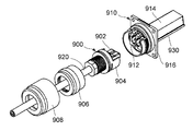
特許文献1は、プラグ(プラグコネクタ)とレセプタクル(レセプタクルコネクタ)とを備えるコネクタ接続体(コネクタ装置)を開示している。図33に示されるように、特許文献1のプラグ900は、光ケーブル920の端部に取り付けられている。詳しくは、プラグ900は、光ケーブル920の端部に取り付けられた光コネクタ本体902を有している。また、プラグ900は、光コネクタ本体902を保持するハウジング904と、ハウジング904に取り付けられる内側シェル906と、外側シェル908とを有している。一方、レセプタクル910は、電子機器(図示せず)の筐体(図示せず)に取り付けられている。レセプタクル910は、プラグ900と嵌合したときに、光コネクタ本体902と接続される相手側光コネクタ912を有している。また、レセプタクル910は、筐体内に収容される基板930に搭載される光トランシーバ914と、筐体に固定される筐体シェル916とを有している。プラグ900とレセプタクル910とが嵌合した状態で、光トランシーバ914は、光ケーブル920を通して伝送される光信号と基板930の配線(図示せず)を通して伝送される電気信号とを相互に変換する。
特許文献1のコネクタ接続体において、光トランシーバ914は、基板930に直接搭載されている。そのため、光トランシーバ914が故障した場合に、光トランシーバ914の交換が困難である。そこで、光トランシーバの交換を容易にするため、基板に搭載される電気コネクタと、その電気コネクタに挿抜可能に構成された光モジュールとの組み合わせが既に開発されている。特許文献2は、そのような組み合わせに用いられる電気コネクタを開示している。図34に示されるように、特許文献2の電気コネクタ950は、基板960に搭載された電気コネクタ本体952と、電気コネクタ本体952を囲うシェル954,956とを備えている。
In the connector connector of
特許文献2の電気コネクタ本体952に接続される光モジュールは、電気コネクタ本体952に接続される他の電気コネクタ(第1電気コネクタ)を備えている。第1電気コネクタと電気コネクタ本体952(第2電気コネクタ)とが適切に接続された状態で、光モジュールは、その略全体が筐体の内部に位置することになる。そのため、光モジュールからの熱は、電子機器の筐体内に放出され、筐体内の温度を上昇させる。筐体内の温度上昇は、電子機器の誤動作や故障を招く可能性がある。しかも、近年の信号伝送速度の上昇に伴い、光モジュールの動作速度が上昇し、発熱量も増加している。
The optical module connected to the electric connector
そこで、本発明は、光モジュールを筐体外に配置してなるコネクタ装置を提供することを目的とする。 Therefore, an object of the present invention is to provide a connector device in which an optical module is arranged outside a housing.
光モジュールを筐体の外、即ち、プラグコネクタに設けようとすると、光モジュールに設けられた第1電気コネクタとレセプタクルコネクタに設けられた、即ち筐体内にある、第2電気コネクタとの間のアライメントや接続確立の確認が困難になる。 When the optical module is to be provided outside the housing, that is, in the plug connector, between the first electric connector provided in the optical module and the second electric connector provided in the receptacle connector, that is, inside the housing. It becomes difficult to confirm alignment and connection establishment.
そこで、本発明は、プラグコネクタの第1電気コネクタとレセプタクルコネクタの第2電気コネクタとの間のアライメント及び接続確立の確認を容易に行えるようにするための構造的条件を限定することとした。 Therefore, the present invention has decided to limit the structural conditions for facilitating the alignment between the first electric connector of the plug connector and the second electric connector of the receptacle connector and the confirmation of the establishment of the connection.
具体的には、本発明は、第1のコネクタ装置として、嵌合方向に沿って互いに嵌合可能なプラグコネクタとレセプタクルコネクタとを備えるコネクタ装置であって、
前記プラグコネクタは、ケーブル保持部と、光電変換部と、第1電気コネクタと、第1ロック部とを備えており、
前記ケーブル保持部は、光信号を伝送させる光ファイバケーブルを保持しており、
前記第1電気コネクタは、前記光電変換部に対して電気信号を入出力するものであり、
前記光電変換部は、前記光信号と前記電気信号とを相互に変換するものであり、
前記嵌合方向において、前記第1ロック部と前記第1電気コネクタとは第1距離だけ離れており、
前記レセプタクルコネクタは、第2ロック部と第2電気コネクタとを備えており、
前記第2ロック部は、前記プラグコネクタと前記レセプタクルコネクタとが互いに嵌合したとき、前記第1ロック部と係合するものであり、
前記第2電気コネクタは、前記プラグコネクタと前記レセプタクルコネクタとが互いに嵌合したとき、前記第1電気コネクタと接続するものであり、
前記嵌合方向において、前記第2ロック部と前記第2電気コネクタとは第2距離だけ離れており、
前記第1距離と前記第2距離の差は、前記第1電気コネクタと前記第2電気コネクタとの間の有効接触長以下である
コネクタ装置を提供する。
Specifically, the present invention is a connector device including a plug connector and a receptacle connector that can be fitted to each other along the fitting direction as the first connector device.
The plug connector includes a cable holding portion, a photoelectric conversion portion, a first electric connector, and a first locking portion.
The cable holding portion holds an optical fiber cable for transmitting an optical signal.
The first electric connector inputs / outputs an electric signal to / from the photoelectric conversion unit.
The photoelectric conversion unit mutually converts the optical signal and the electric signal.
In the fitting direction, the first lock portion and the first electric connector are separated by a first distance.
The receptacle connector includes a second lock portion and a second electric connector.
The second lock portion engages with the first lock portion when the plug connector and the receptacle connector are fitted to each other.
The second electric connector connects to the first electric connector when the plug connector and the receptacle connector are fitted to each other.
In the fitting direction, the second lock portion and the second electric connector are separated by a second distance.
Provided is a connector device in which the difference between the first distance and the second distance is equal to or less than the effective contact length between the first electric connector and the second electric connector.
また、本発明は、第2のコネクタ装置として、第1のコネクタ装置であって、
前記プラグコネクタは、光コネクタと、光モジュールと、第1シェルとを備えており、
前記光コネクタは、前記光ファイバケーブルの先端に取り付けられており、
前記光モジュールは、前記光電変換部と前記第1電気コネクタとを備えており、
前記光モジュールは、前記光コネクタと嵌合されており、
前記第1シェルは、前記光コネクタと前記光モジュールを保持していると共に少なくとも部分的に前記光コネクタと前記光モジュールを覆うものであり、
前記光モジュールは、前記第1シェル内において前記嵌合方向における移動が規制されており、
前記第1ロック部は前記第1シェルに設けられている
コネクタ装置を提供する。
Further, the present invention is a first connector device as a second connector device.
The plug connector includes an optical connector, an optical module, and a first shell.
The optical connector is attached to the tip of the optical fiber cable.
The optical module includes the photoelectric conversion unit and the first electric connector.
The optical module is fitted with the optical connector and
The first shell holds the optical connector and the optical module, and at least partially covers the optical connector and the optical module.
The optical module is restricted from moving in the mating direction within the first shell.
The first lock portion provides a connector device provided on the first shell.
また、本発明は、第3のコネクタ装置として、第2のコネクタ装置であって、
前記光モジュールは、前記嵌合方向と直交する方向へ張り出した張出部を有しており、
前記第1シェルは、第1規制部と第2規制部とを有しており、
前記第1規制部と前記第2規制部は、前記嵌合方向において前記張出部を挟み込んでいる
コネクタ装置を提供する。
Further, the present invention is a second connector device as a third connector device.
The optical module has an overhanging portion that overhangs in a direction orthogonal to the fitting direction.
The first shell has a first regulation part and a second regulation part, and has a first regulation part and a second regulation part.
The first regulating portion and the second regulating portion provide a connector device that sandwiches the overhanging portion in the fitting direction.
また、本発明は、第4のコネクタ装置として、第3のコネクタ装置であって、
前記第1シェルは、前記光モジュールを保持する第1部材と、前記光コネクタを保持する第2部材とを備えており、
前記第1規制部は、前記第1部材に設けられており、前記第2規制部は、前記第2部材に設けられている
コネクタ装置を提供する。
Further, the present invention is a third connector device as a fourth connector device.
The first shell includes a first member that holds the optical module and a second member that holds the optical connector.
The first regulation unit is provided on the first member, and the second regulation unit provides a connector device provided on the second member.
また、本発明は、第5のコネクタ装置として、第4のコネクタ装置であって、
前記プラグコネクタは、前記第1部材と前記第2部材とを締結するためのカップリングナットを備えており、
前記第1部材と前記第2部材とを締結する前の状態において、前記カップリングナットは、前記嵌合方向に移動可能となるように、前記第2部材に取り付けられている
コネクタ装置を提供する。
Further, the present invention is a fourth connector device as a fifth connector device.
The plug connector includes a coupling nut for fastening the first member and the second member.
The coupling nut provides a connector device attached to the second member so as to be movable in the fitting direction in a state before the first member and the second member are fastened. ..
また、本発明は、第6のコネクタ装置として、第5のコネクタ装置であって、
前記第1部材と前記第2部材とを締結する前の状態において、前記第1シェルは、前記嵌合方向に直交する方向に開口した開口部を有しており、
前記第1部材と前記第2部材とを締結する前の状態において、前記張出部は、前記開口部を通じて視認可能である
コネクタ装置を提供する。
Further, the present invention is a fifth connector device as the sixth connector device.
In the state before fastening the first member and the second member, the first shell has an opening opened in a direction orthogonal to the fitting direction.
In a state before fastening the first member and the second member, the overhanging portion provides a connector device that is visible through the opening.
また、本発明は、第7のコネクタ装置として、第6のコネクタ装置であって、
前記第1シェルは、第1止水部及び第2止水部を更に備えており、
前記第1止水部は、前記第1部材に取り付けられ、かつ前記嵌合方向と直交する面内において前記第1部材の全周を覆っており、
前記第2止水部は、前記第2部材に取り付けられ、かつ前記嵌合方向と直交する面内において前記第2部材の全周を覆っており、
前記開口部は、前記嵌合方向において、前記第1止水部と前記第2止水部との間に位置している
コネクタ装置を提供する。
Further, the present invention is a sixth connector device as the seventh connector device.
The first shell further includes a first water stop portion and a second water stop portion.
The first water stop portion is attached to the first member and covers the entire circumference of the first member in a plane orthogonal to the fitting direction.
The second water stop portion is attached to the second member and covers the entire circumference of the second member in a plane orthogonal to the fitting direction.
The opening provides a connector device located between the first water stop and the second water stop in the fitting direction.
また、本発明は、第8のコネクタ装置として、第4から第7までのコネクタ装置のうちの一つであって、
前記プラグコネクタは、複数の板バネを有する支持部材を更に備えており、
前記支持部材は、前記嵌合方向と直交する面内において、前記光モジュールを前記第1部材に対してフローティング状態となるように支持している
コネクタ装置を提供する。
Further, the present invention is one of the fourth to seventh connector devices as the eighth connector device.
The plug connector further includes a support member having a plurality of leaf springs.
The support member provides a connector device that supports the optical module so as to float with respect to the first member in a plane orthogonal to the fitting direction.
また、本発明は、第9のコネクタ装置として、第2から第8までのコネクタ装置のうちの一つであって、
前記第1シェルは、前記嵌合方向と直交する面内において全周に亘って前記光モジュールを囲っており、
前記第1シェルと前記光モジュールとの間には、前記嵌合方向に延びるケージ収容部が形成されており、
前記レセプタクルコネクタは、ケージを有しており、
前記プラグコネクタを前記レセプタクルコネクタと嵌合する際、前記ケージは前記ケージ収容部に部分的に収容される
コネクタ装置を提供する。
Further, the present invention is one of the second to eighth connector devices as the ninth connector device.
The first shell surrounds the optical module over the entire circumference in a plane orthogonal to the fitting direction.
A cage accommodating portion extending in the fitting direction is formed between the first shell and the optical module.
The receptacle connector has a cage and
When mating the plug connector with the receptacle connector, the cage provides a connector device that is partially housed in the cage housing.
また、本発明は、第10のコネクタ装置として、第9のコネクタ装置であって、
前記レセプタクルコネクタは、使用時において筐体に取り付けられる第2シェルを更に備えており、
前記第2電気コネクタは、使用時において前記筐体内に配置されている回路基板上に固定されるものであり、
前記第2ロック部は、前記筐体の外側に位置するように、前記第2シェルに設けられている
コネクタ装置を提供する。
Further, the present invention is a ninth connector device as the tenth connector device.
The receptacle connector further comprises a second shell that attaches to the enclosure during use.
The second electric connector is fixed on a circuit board arranged in the housing at the time of use.
The second lock portion provides a connector device provided on the second shell so as to be located outside the housing.
また、本発明は、第11のコネクタ装置として、第10のコネクタ装置であって、
前記ケージは、使用時において、前記回路基板上に固定されるものであり、
前記ケージは、導電性を有し、かつ前記第2電気コネクタを収容しており、
前記第2シェルは、導電性を有しており、
前記第2シェルは、前記嵌合方向において、前記第2ロック部と前記第2電気コネクタとの距離が前記第2距離となるように、前記ケージに取り付けられて
コネクタ装置を提供する。
Further, the present invention is the tenth connector device as the eleventh connector device.
The cage is fixed on the circuit board at the time of use.
The cage is conductive and houses the second electrical connector.
The second shell has conductivity and is
The second shell is attached to the cage so that the distance between the second lock portion and the second electric connector is the second distance in the fitting direction to provide the connector device.
また、本発明は、第12のコネクタ装置として、第11のコネクタ装置であって、
前記第2シェルは、前記嵌合方向に延びる腕部を有しており、
前記腕部は、前記ケージに取り付けられ、それによって、前記第2ロック部と前記第2電気コネクタとの間の距離を前記第2距離に固定する
コネクタ装置を提供する。
Further, the present invention is the eleventh connector device as the twelfth connector device.
The second shell has an arm portion extending in the mating direction.
The arm is attached to the cage, thereby providing a connector device that fixes the distance between the second lock and the second electrical connector to the second distance.
また、本発明は、相手側ロック部と相手側電気コネクタとを備えたレセプタクルコネクタと嵌合方向に沿って嵌合可能なプラグコネクタであって、
前記プラグコネクタは、ケーブル保持部と、光電変換部と、電気コネクタと、ロック部とを備えており、
前記ケーブル保持部は、光信号を伝送させる光ファイバケーブルを保持しており、
前記電気コネクタは、前記光電変換部に対して電気信号を入出力するものであり、
前記光電変換部は、前記光信号と前記電気信号とを相互に変換するものであり、
前記嵌合方向において、前記ロック部と前記電気コネクタとは第1距離だけ離れており、
前記ロック部は、前記プラグコネクタと前記レセプタクルコネクタとが互いに嵌合したとき、前記相手側ロック部と係合するものであり、
前記電気コネクタは、前記プラグコネクタと前記レセプタクルコネクタとが互いに嵌合したとき、前記相手側電気コネクタと接続するものであり、
前記嵌合方向において、前記相手側ロック部と前記相手側電気コネクタとの距離が第2距離のとき、前記第1距離と前記第2距離との差が、前記電気コネクタと相手側電気コネクタとの間の有効接触長以下である
プラグコネクタを提供する。
Further, the present invention is a plug connector that can be fitted along a mating direction with a receptacle connector having a mating lock portion and a mating electrical connector.
The plug connector includes a cable holding portion, a photoelectric conversion portion, an electric connector, and a lock portion.
The cable holding portion holds an optical fiber cable for transmitting an optical signal.
The electric connector inputs / outputs an electric signal to / from the photoelectric conversion unit.
The photoelectric conversion unit mutually converts the optical signal and the electric signal.
In the mating direction, the lock portion and the electric connector are separated by a first distance.
The lock portion engages with the mating lock portion when the plug connector and the receptacle connector are fitted to each other.
The electric connector connects to the other side electric connector when the plug connector and the receptacle connector are fitted to each other.
When the distance between the mating side lock portion and the mating side electric connector is the second distance in the mating direction, the difference between the first distance and the second distance is the difference between the electric connector and the mating side electric connector. Provided are plug connectors that are less than or equal to the effective contact length between.
本発明のプラグコネクタの第1ロック部と第1電気コネクタとは、嵌合方向において、第1距離だけ離れており、レセプタクルコネクタの第2ロック部と第2電気コネクタとは、嵌合方向において、第2距離だけ離れている。そして、第1距離と第2距離の差は、第1電気コネクタと第2電気コネクタとの間の有効接触長以下である。換言すると、このような条件を満たすように第1距離と第2距離とを設定する。このうち、第1距離は意図せずともプラグコネクタの設計段階において定まる。しかし、第2距離については、意図すれば様々な設計が可能である一方で、意図しなければ、特許文献1の0056段落に記載されているように、組立ばらつき生じてしまう。この点を考慮して前述の構造的条件を設定したことから、本発明のコネクタ装置は、第1電気コネクタと第2電気コネクタとのアライメント及び接続確立の確認を容易に行うことができる。
The first lock portion and the first electric connector of the plug connector of the present invention are separated by a first distance in the fitting direction, and the second lock portion and the second electric connector of the receptacle connector are separated from each other in the fitting direction. , Only the second distance away. The difference between the first distance and the second distance is equal to or less than the effective contact length between the first electric connector and the second electric connector. In other words, the first distance and the second distance are set so as to satisfy such a condition. Of these, the first distance is unintentionally determined at the plug connector design stage. However, while various designs are possible for the second distance if intended, if it is not intended, assembly variation will occur as described in paragraph 0056 of
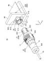
図1及び図2を参照すると、本発明の一実施の形態によるコネクタ装置10は、プラグコネクタ11とレセプタクルコネクタ50とを備えている。プラグコネクタ11は、光ファイバケーブル70の端部に取り付けられており、レセプタクルコネクタ50は、電子機器(図示せず)の筐体80と回路基板85とに取り付けられている。
Referring to FIGS. 1 and 2, the
図1及び図2から理解されるように、プラグコネクタ11とレセプタクルコネクタ50とは、嵌合方向に沿って互いに嵌合可能かつ分離可能である。本実施の形態において、嵌合方向は、前後方向に沿った方向であり、前後方向はY方向である。また、+Y方向が前方であり、−Y方向が後方である。
As can be seen from FIGS. 1 and 2, the
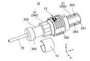
図3を参照すると、プラグコネクタ11は、プラグコネクタ本体13とストッパー15とを有している。ストッパー15は、円筒の一部を切り取ったような形状をしている。詳しくは、ストッパー15は、前後方向に沿って見たときの形状がC形であり、前後方向に沿って延びている。ストッパー15は、周方向の二つの端部間の距離を変更するように弾性変形可能である。この弾性変形を利用することにより、ストッパー15は、プラグコネクタ本体13に対して着脱可能である。
Referring to FIG. 3, the
図4に示されるように、プラグコネクタ本体13は、前部21と後部31とを有している。図4及び図5から理解されるように、前部21と後部31とは、前後方向に沿って互いに着脱可能である。図5及び図6から理解されるように、後部31は、前後方向に沿って移動可能なカップリングナット340を有している。カップリングナット340は、前部21と後部31とを締結する。ストッパー15(図3参照)は、プラグコネクタ本体13の後部31に取り付けられ、カップリングナット340の後方への移動を規制する。
As shown in FIG. 4, the plug connector
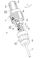
図7から図10を参照すると、プラグコネクタ本体13の前部21は、光モジュール210、フロントホルダ250、支持部材270、ロックリング280、ロックスプリング290及び操作部292を備えている。また、プラグコネクタ本体13の後部31は、光コネクタ310、ケーブル保持部320、リアホルダ330、カップリングナット340及びリアキャップ350を備えている。本実施の形態において、フロントホルダ250、支持部材270、ロックリング280、ロックスプリング290、操作部292及びリアホルダ330は、第1シェルを構成する。詳しくは、第1シェルは、光モジュール210を保持する第1部材と、光コネクタ310を保持する第2部材とを備えている。第1部材は、フロントホルダ250、支持部材270、ロックリング280、ロックスプリング290及び操作部292からなる。第2部材は、リアホルダ330からなる。このように、プラグコネクタ11は、光コネクタ310と、光モジュール210と、第1シェルとを備えている。また、プラグコネクタ11は、第1部材と第2部材とを締結するためのカップリングナット340を備えている。カップリングナット340は、第1部材と第2部材とを締結する前の状態において、前後方向に沿って移動可能となるように第2部材に取り付けられている。
Referring to FIGS. 7 to 10, the
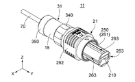
図9に示されるように、光モジュール210は、主部220と張出部240とを有している。主部220は、概ね直方体の形状を有しており、前後方向に延びている。張出部240は、主部220の後方に位置している。張出部240は、前後方向に沿って見たとき、主部220よりも外側へ張り出している。換言すると、張出部240は、前後方向と直交する方向へ張り出している。本実施の形態において、光モジュール210は、SFP(Small Form-factor Pluggable)モジュールである。
As shown in FIG. 9, the
図9に示されるように、光モジュール210は、また、光電変換部229と第1電気コネクタ231とを備えている。光モジュール210は、光コネクタ310と接続され、光コネクタ310へ光信号を送信し、また、光コネクタ310からの光信号を受信する。第1電気コネクタ231は、光電変換部229に対して電気信号を入出力する。光電変換部229は、光コネクタ310と第1電気コネクタ231との間において、光信号と電子信号とを相互に変換する。本実施の形態において、光電変換部229と第1電気コネクタ231は、主部220に設けられている。第1電気コネクタ231は、主部220に設けられた回路基板233の縁に形成された複数のコンタクトパッド(図示せず)を備えるエッジコネクタである。このように、プラグコネクタ11は、光電変換部229と第1電気コネクタ231とを備えている。
As shown in FIG. 9, the
図8から図10に示されるように、光モジュール210は、支持部材270を介してフロントホルダ250に保持されている。フロントホルダ250には、支持部材270及び光モジュール210の一部を受容する受容部251が形成されている。後述するように、受容部251を規定するフロントホルダ250の縁部253が、第1規制部として機能する。
As shown in FIGS. 8 to 10, the
図7及び図8に示されるように、フロントホルダ250は、レセプタクルコネクタ50に挿入される挿入部261を有している。挿入部261には、前後方向に沿った中心軸に向かって凹み、前後方向に沿って延びる複数のガイド溝263が形成されている。本実施の形態において、ガイド溝263の数は四つである。ガイド溝263は、前後方向に沿った中心軸関して非対称となるように配置されている。
As shown in FIGS. 7 and 8, the
図9から理解されるように、光モジュール210は、前後方向と直交する面内において、フロントホルダ250及び操作部292により囲われている。換言すると、第1シェルは、前後方向と直交する面内において、全周に亘って光モジュール210を囲っている。そして、光モジュール210と第1シェルとの間、即ち、光モジュール210とフロントホルダ250との間には、前後方向に延びるケージ収容部255が形成されている。
As can be seen from FIG. 9, the
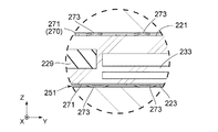
図8から図10までの図から理解されるように、支持部材270は、四角筒状に形成され、四つの板状部271を有している。各板状部271には、面内方向と直交する方向に突出した複数の板バネ273が形成されている。このように、プラグコネクタ11は、複数の板バネ273を有する支持部材270を備えている。本実施の形態において、支持部材270は、金属板を打ち抜き加工及び曲げ加工して形成されている。板バネ273も同時に、曲げ加工により形成される。
As can be understood from the views of FIGS. 8 to 10, the
図8から図10に示されるように、四つの板状部271のうち上側及び下側の板状部271は、光モジュール210の主部220の上面221及び下面223を夫々部分的に覆っている。また、上側及び下側の板状部271の夫々は、上下方向において、光モジュール210とフロントホルダ250の内面との間に挟まれている。板バネ273の働きにより、光モジュール210は、上下方向において、フロントホルダ250に対しフローティング状態となるように支持される。四つの板状部271のうちの残りの二つの板状部271は、光モジュール210の側面225,227を夫々部分的に覆う。但し、光モジュール210の側面225,227には、板状部271に対応する凹所が形成されており、その凹所に板状部271が収容されている。そのため、図8において、側面225,227を覆う板状部271は見えない。しかしながら、支持部材270は、横方向に関しても光モジュール210をフロントホルダ250に対してフローティング状態となるように支持する。こうして、光モジュール210は、前後方向と直交する面内において、フロントホルダ250に対してフローティング状態となるように支持される。光モジュール210の周囲を金属製の支持部材270で囲んだことにより、光モジュール210からのノイズ放射を抑制すると共に放熱を促進することができる。なお、本実施の形態において、上下方向はZ方向である。+Z方向が上方であり、−Z方向が下方である。また、本実施の形態において、横方向はX方向である。
As shown in FIGS. 8 to 10, the upper and lower plate-shaped
図8及び図9から理解されるように、ロックリング280は、概ね円筒形状に形成されている。また、図8に示されるように、ロックリング280には、内周側へ突出する一対のロック部(第1ロック部)281が設けられている。即ち、プラグコネクタ11は、第1ロック部281を備えている。図27から理解されるように、ロック部281は前後方向と直交するロック面283を有している。前後方向において、ロック部281と第1電気コネクタ231とは、第1距離D1だけ離れている。
As can be seen from FIGS. 8 and 9, the
図8及び図9から理解されるように、ロックリング280は、フロントホルダ250の一部分を全周に亘って囲うように、フロントホルダ250に取り付けられている。ロックリング280は、前後方向において、フロントホルダ250の中央部近くに設けられている。ロックリング280は、前後方向に沿った軸に関して、フロントホルダ250に対して所定の角度範囲で回転可能である。ロックリング280は、ロックスプリング290によって所定角度位置に維持されている。
As can be seen from FIGS. 8 and 9, the
図7から図9までの図から理解されるように、操作部292は、前後方向と直交する面内において、ロックリング280及びロックスプリング290を覆うように、フロントホルダ250に取り付けられている。操作部292は、フロントホルダ250に取り付けられた状態で、前後方向に沿って第1位置と第2位置の間で移動することが可能である。操作部292とロックリング280とは、カム機構285により互いに連結されている。初期状態において、操作部292は、第2位置よりも前方に位置する第1位置に位置している。操作部292を第1位置から第2位置へ向かって後方へ移動させると、カム機構285の働きにより、ロックリング280がロックスプリング290の力に逆らって回転する。操作部292が外力から解放されると、ロックリング280がロックスプリング290の力により所定角度位置に戻る。これに伴い、操作部292は、カム機構285の働きによって、第1位置に戻る。後述するように、操作部292が第1位置にあるとき、ロックリング280のロック部281は、被ロック部(第2ロック部)511(図16、図17及び図27参照)をロックすることができる。また、操作部292が第2位置にあるとき、ロックリング280のロック部281は、レセプタクルコネクタ50が備える被ロック部511のロックを解除することができる。
As can be understood from the drawings of FIGS. 7 to 9, the
図9に示されるように、光コネクタ310は、光信号を伝送させる光ファイバケーブル70の先端に取り付けられている。詳しくは、光コネクタ310は、光ファイバケーブル70に含まれる光ファイバ71の先端にフェルール73を介して取り付けられている。光コネクタ310は、光モジュール210に対して着脱可能に構成されている。
As shown in FIG. 9, the
図9に示されるように、ケーブル保持部320は、光信号を伝送させる光ファイバケーブル70を保持している。詳しくは、光ファイバケーブル70の外被75の先端部分において、光ファイバケーブル70を保持している。ケーブル保持部320は、前後方向に沿った軸に関して、光ファイバケーブル70を回転不能に保持している。光ファイバ71は、外被75の先端部分よりも更に前方へ延びている。
As shown in FIG. 9, the
図4及び図5から理解されるように、前部21と後部31とは、互いに組み合わされる。換言すると、第1部材と第2部材とは互いに組み合わされる。前部21と後部31とが互いに組み合わされた状態で、光コネクタ310と光モジュール210とは互いに嵌合している。この状態において、第1シェルは、光コネクタ310と光モジュール210を保持していると共に少なくとも部分的に光コネクタ310と光モジュール210を覆っている。カップリングナット340を用いて前部21と後部31とを互いに締結する前の状態において、プラグコネクタ本体13には、開口部257が存在する。換言すると、第1部材と第2部材とを締結する前の状態において、第1シェルは、前後方向と直交する方向に開口した開口部257を有している。そして、開口部257を通じて、光モジュール210及び光コネクタ310を部分的に視認することができる。特に、開口部257を通じて、光モジュール210の張出部240を部分的に視認することができる。これにより、光モジュール210と光コネクタ310との嵌合状態を目視確認できる。また、リアホルダ330の前端(第2規制部)331が光モジュール210に突き当たっているか否かを目視で確認することができる。
As can be seen from FIGS. 4 and 5, the front 21 and the rear 31 are combined with each other. In other words, the first member and the second member are combined with each other. The
再び図9を参照すると、張出部240は、少なくとも部分的に、フロントホルダ250の縁部253とリアホルダ330の前端331との間に挟まれている。換言すると、第1シェルは、第1部材に設けられた第1規制部253と第2部材に設けられた第2規制部331とを有しており、第1規制部253と第2規制部331は、前後方向において張出部240を挟み込んでいる。これにより、光モジュール210は、第1シェル内において、前後方向における移動が規制される。ここで、張出部240の前後方向の長さは、光モジュール210の製造者によって異なる可能性がある。そこで、光モジュール210の前後方向の移動を確実に規制するため、リアホルダ330の前端331には、フォームスプリングが設けられてよい。また、フォームスプリングの表面には潤滑用フィルムが貼られてよい。これにより、光モジュール210の張出部240をフロントホルダ250の縁部2532とリアホルダ330の前端331で確実に挟み込むことができる。換言すると、張出部240は、第2規制部331及びフォームスプリングによって前方へ押され、第1規制部253に押し付けられる。こうして、張出部240が第1規制部253に接触した状態を、確実に維持することができる。よって、光モジュール210の主部220の寸法が所定の公差内であれば、張出部240の寸法の影響を受けることなく、第1電気コネクタ231と第2電気コネクタ57(図26参照)との接続を確実に行うことができる。
Referring again to FIG. 9, the
図6に示されるように、後部31が備えるカップリングナット340を前部21の雄ネジ部259に螺合させることで、前部21と後部31とは互いに締結される。雄ネジ部259は、図4及び図5に示されるように、フロントホルダ250の後部31の外周に形成されている。開口部257は、雄ネジ部259を途中で切断するようにフロントホルダ250に形成されている。
As shown in FIG. 6, the
図9に示されるように、前部21には、更に第1止水部294が設けられており、後部31には、更に第2止水部352が設けられている。換言すると、第1シェルは、第1止水部294と第2止水部352を備えており、第1止水部294は第1部材に取り付けられ、第2止水部352は第2部材に取り付けられている。第1止水部294は、前後方向と直交する面内において第1部材に含まれるフロントホルダ250の全周を覆っており、第2止水部352は、前後方向と直交する面内において、第2部材であるリアホルダ330の全周を覆っている。カップリングナット340が雄ネジ部259に締め付けられると、第1止水部294は、カップリングナット340とフロントホルダ250との間に挟まれて、これらの間を止水する。また、第2止水部352は、カップリングナット340とリアホルダ330との間に挟まれて、これらの間を止水する。開口部257は、前後方向において、第1止水部294と第2止水部352との間に位置する。これにより、カップリングナット340が雄ネジ部259に締め付けられると、開口部257は外部から遮断される。前部21は、更に第3止水部296を有している。
As shown in FIG. 9, the
図1及び図11から図15に示されるように、レセプタクルコネクタ50は、レセプタクル(第2シェル)51と、ケージ55と、第2電気コネクタ57とを備えている。
As shown in FIGS. 1 and 11 to 15, the
図16から図18に示されるように、レセプタクル51は、環状部510と、鍔部520と、三つの腕部530とを有している。レセプタクル51は、金属製であり、導電性を有している。
As shown in FIGS. 16 to 18, the
図16から図18に示されるように、環状部510の外周面には、被ロック部(第2ロック部)511が形成されている。換言すると、レセプタクルコネクタ50は、第2ロック部511を備えている。被ロック部511は、横方向の内側に凹む凹部である。被ロック部511は、プラグコネクタ11とレセプタクルコネクタ50とが互いに嵌合したとき、ロック部281と係合する。詳しくは、被ロック部511を規定する壁面は、前後方向と直交する被ロック面513を有している。ロック部281が被ロック部511をロックした状態において、プラグコネクタ11をレセプタクルコネクタ50に対して相対的に後方へ移動させようとすると、ロック面283(図27参照)が被ロック面513に突き当たる。これにより、レセプタクルコネクタ50からプラグコネクタ11を抜去することが防止される。
As shown in FIGS. 16 to 18, a locked portion (second locked portion) 511 is formed on the outer peripheral surface of the
図16から図18に示されるように、環状部510及び鍔部520の内周面には、四つのガイド突起515が形成されている。ガイド突起515は、環状部510の中心へ向かって突出し、前後方向に延びる突部である。ガイド突起515は、誤嵌合防止のため、環状部510の中心軸に関して非回転対称となる位置に配置されている。
As shown in FIGS. 16 to 18, four
図16から図18に示されるように、鍔部520は、環状部510の前方に位置し、環状部510の外周面よりも上下方向及び横方向において外側へ突出している。特に図18に示されるように、鍔部520は、前後方向に沿ってみたときの形状は、略正方形である。
As shown in FIGS. 16 to 18, the
図16から図18を参照すると、三つの腕部530は、上腕部531と、一対の側腕部533とを有している。腕部530は、前後方向に沿って延びている。詳しくは、上腕部531は、鍔部520から前方へ延びる支持部541と、支持部541の先端から横方向及び下方へ延びる先端部543とを有している。また、側腕部533は、二つのガイド突起515に連続して、前方へ延びる支持部545と、支持部545の先端から横方向内側へ延びる先端部547とを有している。
Referring to FIGS. 16-18, the three
図19及び図20に示されるように、ケージ55は、後部551と前部553とを有している。ケージ55は、後部551と前部553とにまたがる内部空間555を有している。後部551は、上下方向外側及び横方向外側へ突出する複数の板バネ557を有している。また、後部551は、部分的に下方へ向かって開放されている。また、前部553は、下方に向かって開放されている。前部553は、上板561、側板563及び前板565を有している。ケージ55は、金属板を打ち抜き加工及び曲げ加工して形成され、導電性を有している。
As shown in FIGS. 19 and 20, the
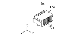
図21及び図22から理解されるように、第2電気コネクタ57は、エッジコネクタである。第2電気コネクタ57は、プラグコネクタ11とレセプタクルコネクタ50とが互いに嵌合したとき、第1電気コネクタ231と接続される。本実施の形態において、第2電気コネクタ57は、複数のコンタクト571を有している。コンタクト571は絶縁性のコンタクトホルダ573に保持されている。図24及び図25から理解されるように、コンタクト571は、接点572を有しており、接点572は、上下二列に配列されている。
As can be seen from FIGS. 21 and 22, the second
図23から図25に示されるように、ケージ55及び第2電気コネクタ57は、使用時において、回路基板85に搭載(固定)される。また、第2電気コネクタ57は、ケージ55の内部空間555内に収容される。
As shown in FIGS. 23 to 25, the
図11から図15までの図から理解されるように、回路基板85は、使用時において筐体80の内部に配置される。回路基板85上に搭載された第2電気コネクタ57もまた、使用時において、筐体80の内部に配置される。また、レセプタクル51は、使用時において筐体80に取り付けられる。このとき、環状部510及び鍔部520は、筐体80の外側に位置し、腕部530は孔81通じて筐体80の内部へ延びている。ここで、回路基板85は、筐体80に直接固定されておらず、他の部材(図示せず)等を介して間接的に筐体80に固定されている。そのため、筐体80に形成された孔81と回路基板85との間の相対的位置には、ばらつきがある。したがって、レセプタクル51を筐体80に取り付ける際に、レセプタクル51の位置合わせを行う必要がある。なお、本実施の形態において、筐体80と回路基板85との間の前後方向の距離は、図示しない位置決め治具を用いて適切に調整されているものとする。詳しくは、図27に示されるように、前後方向において、被ロック面513と第2電気コネクタ57の後端との距離L1と、被ロック面513と鍔部520の前面との距離L2と、鍔部520の前面と第2電気コネクタ57の後端との距離L3とが、夫々所定の公差内に収まるように調整する。
As can be seen from the views of FIGS. 11 to 15, the
図11から図15までの図から理解されるように、レセプタクル51の腕部530の形状及び配置は、ケージ55のサイズに対応している。したがって、レセプタクル51の腕部530を筐体80の孔81に挿入し、ケージ55に接触させることで、前後方向と直交する面内方向において、レセプタクル51の筐体80に対する位置決めを行うことができる。また、前後方向に沿った軸に関する回転方向において、筐体80に対するレセプタクル51の角度も決定できる。換言すると、レセプタクル51の鍔部520を筐体80の外面に接触させた状態において、上腕部531の先端部543がケージ55の上板561の前縁部に接触し、かつ側腕部533の先端部547の端面とケージ55の側板563の表面とが同一平面上に位置するようにする。筐体80と回路基板85との相対的位置関係が適切であれば、このとき、先端部543及び547の前面は、ケージ55の前板565の背面と同一平面上に位置する。こうして、筐体80の孔81に対するレセプタクル51の位置決めが行われる。その後、レセプタクル51は、ボルト(図示せず)を用いて筐体80に固定される。その結果、レセプタクル51は、ケージ55に取り付けられる。鍔部520には、ボルトを挿入するための馬鹿穴(図示せず)が形成されている。
As can be seen from the views of FIGS. 11 to 15, the shape and arrangement of the
図13に示されるように、被ロック部511は、筐体80の外側に位置する。換言すると、第2ロック部511は、筐体80の外側に位置するように、第2シェルに設けられている。また、レセプタクル51は、前後方向において、被ロック部511と第2電気コネクタ57との距離が第2距離D2となるように、筐体80に固定されかつケージ55に固定されることなく取り付けられている。詳しくは、第2距離D2は、被ロック部511の被ロック面513と第2電気コネクタ57のコンタクト571の接点572(図25参照)との間の前後方向における距離である。腕部530は、ケージ55の所定位置に取り付けられ、それによって、被ロック部511と第2電気コネクタ57との間の距離を第2距離D2に固定する。このように、前後方向において、被ロック部511と第2電気コネクタ57とは、第2距離D2だけ離れている。
As shown in FIG. 13, the locked
図26に示されるように、プラグコネクタ11とレセプタクルコネクタ50とが互いに嵌合する際、ケージ55はケージ収容部255に部分的に収容される。また、第1電気コネクタ231は第2電気コネクタ57に接続される。更に、第3止水部296は、フロントホルダ250とレセプタクル51との間に挟まれ、これらの間を止水する。
As shown in FIG. 26, when the
第1電気コネクタ231及び第2電気コネクタ57は、前後方向において、第2電気コネクタ57のコンタクト571が第1電気コネクタ231のコンタクトパッド(図示せず)に接触する有効接触長D3を有している。換言すると、第1電気コネクタ231のコンタクトパッドは、コンタクト571に接触する範囲として、前後方向の長さが有効接触長D3に等しい接触可能範囲を有している。図26及び図27から理解されるように、第1電気コネクタ231と第2電気コネクタ57とが電気的に正しく接続されるには、ロック部281(ロック面283)から第1電気コネクタ231のコンタクトパッドの接触可能範囲の先端までの距離(第1距離D1)は、被ロック部511(被ロック面513)から第2電気コネクタ57の接点572(図25参照)までの距離(第2距離D2)よりも長くなければならない(D1>D2)。しかしながら、第1距離D1と第2距離D2との差が有効接触長D3を超えると(D1−D2>D3)、ロック部281が被ロック部511をロックすることができない。したがって、第1距離D1と第2距離D2との差は有効接触長D3以下でなければならない。本実施の形態において、プラグコネクタ11及びレセプタクルコネクタ50は、このような条件を満たすように作製されている。したがって、ロック部281が被ロック部511をロックできることを確認すれば、プラグコネクタ11及びレセプタクルコネクタ50はアライメント及び接続確立を確認したことになる。こうして、本実施の形態によるコネクタ装置10は、第1電気コネクタ231と第2電気コネクタ57とのアライメント及び接続確立の確認を容易に行うことができる。
The first
上記実施の形態では、レセプタクル51が備える腕部530を利用してレセプタクル51の位置決めを行う例について説明した。但し、本発明はこれに限られない。腕部530を有しないレセプタクル51A(図30から図32参照)の位置決めを行う場合には、以下に説明する治具を用いて行うことができる。
In the above embodiment, an example in which the
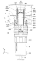
図28及び図29を参照すると、レセプタクル51A(図30から図32参照)の位置決めに使用される治具87は、挿入部871と、Oリング873と、鍔部875と、つまみ877とを有している。図28及び図29に示されるように、挿入部871の外周面には、レセプタクル51Aのガイド突起515A(図32参照)に対応するガイド溝881が形成されている。Oリング873は、挿入部871に形成された溝に部分的に嵌め込まれている。Oリング873は、挿入部871の後端近く、即ち、鍔部875の近くに位置し、前後方向と直交する面内において、挿入部871の全周を囲っている。また、挿入部871には、ケージ55の後部551を受容する受容部879が形成されている。
Referring to FIGS. 28 and 29, the
図30から図32を参照すると、治具87の挿入部871は、レセプタクル51A及び筐体80の孔81に挿入される。このとき、レセプタクル51Aは筐体80に固定されておらず、回路基板85は、筐体80に対して固定されていない。治具87の挿入部871がレセプタクル51Aに挿入されると、レセプタクル51Aのガイド突起515Aと治具87のガイド溝881との相互作用により、治具87とレセプタクル51Aとの相対的位置が決定される。また、挿入部871が筐体80の孔81に挿入されると、ケージ55の後部551が治具87の受容部879に受容される。ケージ55の後端が受容部879の奥壁に突き当たることで、前後方向において、治具87とケージ55との相対的な位置が決定される。あるいは、回路基板85の後端と治具87の前端とが突き当たることで、前後方向において、治具87とケージ55との相対的な位置が決定される。また、ケージ55の後部551が備える板バネ557の作用により、治具87は、前後方向と直交する面内方向において、ケージ55に対して位置決めされる。同時に、治具87は、前後方向に沿った軸に関する回転方向において、ケージ55に対する相対的角度が決定される。以上の結果、治具87を介して、レセプタクル51Aとケージ55との相対的な位置が決定される。この状態で、レセプタクル51Aの鍔部520が、筐体80の表面に接触するように回路基板85の筐体80に対する相対位置を調整し、回路基板85の筐体80に対する相対位置を固定する。その後、レセプタクル51Aを筐体80に固定する。以上のようにして、筐体80に対するケージ55の相対位置と、ケージ55に対するレセプタクル51Aの相対位置とを決定することができる。
Referring to FIGS. 30 to 32, the
なお、上記例では、ケージ55の板バネ557を利用して、ケージ55に対する治具87の相対位置を決定した。しかしながら、本発明はこれに限定されない。ケージ55の板バネ557に代えて、受容部879内に複数の板バネを配置するようにしてもよい。これによりケージ55の構成の簡略化と小型化を実現することができる。
In the above example, the
以上、本発明について、実施の形態を掲げて説明してきたが、本発明は、上記実施の形態に限定されるものではなく、本発明の主旨を逸脱しない範囲で種々の変形、変更が可能である。例えば、上記実施の形態では、レセプタクル51の側腕部533が最終的にケージ55に接していないが、側腕部533もケージ55に接したままとなるようにしてもよい。これにより、より精度の高いレセプタクル51の位置決めを行うことができる。
Although the present invention has been described above with the embodiments, the present invention is not limited to the above-described embodiments, and various modifications and changes can be made without departing from the gist of the present invention. be. For example, in the above embodiment, the
10 コネクタ装置
11 プラグコネクタ
13 プラグコネクタ本体
15 ストッパー
21 前部
210 光モジュール
220 主部
221 上面
223 下面
225,227 側面
229 光電変換部
231 第1電気コネクタ
233 回路基板
240 張出部
250 フロントホルダ
251 受容部
253 縁部(第1規制部)
255 ケージ収容部
257 開口部
259 雄ネジ部
261 挿入部
263 ガイド溝
270 支持部材
271 板状部
273 板バネ
280 ロックリング
281 ロック部(第1ロック部)
283 ロック面
285 カム機構
290 ロックスプリング
292 操作部
294 第1止水部
296 第3止水部
31 後部
310 光コネクタ
320 ケーブル保持部
330 リアホルダ
331 前端(第2規制部)
340 カップリングナット
350 リアキャップ
352 第2止水部
50 レセプタクルコネクタ
51,51A レセプタクル
510 環状部
511 被ロック部(第2ロック部)
513 被ロック面
515,515A ガイド突起
520 鍔部
530 腕部
531 上腕部
541 支持部
543 先端部
533 側腕部
545 支持部
547 先端部
55 ケージ
551 後部
557 板バネ
553 前部
561 上板
563 側板
565 前板
555 内部空間
57 第2電気コネクタ
571 コンタクト
572 接点
573 コンタクトホルダ
70 光ファイバケーブル
71 光ファイバ
73 フェルール
75 外被
80 筐体
81 孔
85 回路基板
87 治具
871 挿入部
873 Oリング
875 鍔部
877 つまみ
879 受容部
881 ガイド溝
10
255
283
340
513
Claims (10)
前記プラグコネクタは、ケーブル保持部と、光電変換部と、第1電気コネクタと、第1ロック部とを備えており、
前記ケーブル保持部は、光信号を伝送させる光ファイバケーブルを保持しており、
前記第1電気コネクタは、前記光電変換部に対して電気信号を入出力するものであり、
前記光電変換部は、前記光信号と前記電気信号とを相互に変換するものであり、
前記嵌合方向において、前記第1ロック部と前記第1電気コネクタとは第1距離だけ離れており、
前記レセプタクルコネクタは、第2ロック部と第2電気コネクタとを備えており、
前記第2ロック部は、前記プラグコネクタと前記レセプタクルコネクタとが互いに嵌合したとき、前記第1ロック部と係合するものであり、
前記第2電気コネクタは、前記プラグコネクタと前記レセプタクルコネクタとが互いに嵌合したとき、前記第1電気コネクタと接続するものであり、
前記嵌合方向において、前記第2ロック部と前記第2電気コネクタとは第2距離だけ離れており、
前記第1距離と前記第2距離の差は、前記第1電気コネクタと前記第2電気コネクタとの間の有効接触長以下であり、
前記プラグコネクタは、光コネクタと、光モジュールと、第1シェルとを備えており、
前記光コネクタは、前記光ファイバケーブルの先端に取り付けられており、
前記光モジュールは、前記光電変換部と前記第1電気コネクタとを備えており、
前記光モジュールは、前記光コネクタと嵌合されており、
前記第1シェルは、前記光コネクタと前記光モジュールを保持していると共に少なくとも部分的に前記光コネクタと前記光モジュールを覆うものであり、
前記光モジュールは、前記第1シェル内において前記嵌合方向における移動が規制されており、
前記第1ロック部は前記第1シェルに設けられており、
前記光モジュールは、前記嵌合方向と直交する方向へ張り出した張出部を有しており、
前記第1シェルは、第1規制部と第2規制部とを有しており、
前記第1規制部と前記第2規制部は、前記嵌合方向において前記張出部を挟み込んでおり、
前記第1シェルは、前記光モジュールを保持する第1部材と、前記光コネクタを保持する第2部材とを備えており、
前記第1規制部は、前記第1部材に設けられており、前記第2規制部は、前記第2部材に設けられている
コネクタ装置。 A connector device including a plug connector and a receptacle connector that can be fitted to each other along the fitting direction.
The plug connector includes a cable holding portion, a photoelectric conversion portion, a first electric connector, and a first locking portion.
The cable holding portion holds an optical fiber cable for transmitting an optical signal.
The first electric connector inputs / outputs an electric signal to / from the photoelectric conversion unit.
The photoelectric conversion unit mutually converts the optical signal and the electric signal.
In the fitting direction, the first lock portion and the first electric connector are separated by a first distance.
The receptacle connector includes a second lock portion and a second electric connector.
The second lock portion engages with the first lock portion when the plug connector and the receptacle connector are fitted to each other.
The second electric connector connects to the first electric connector when the plug connector and the receptacle connector are fitted to each other.
In the fitting direction, the second lock portion and the second electric connector are separated by a second distance.
The difference between the first distance and the second distance is equal to or less than the effective contact length between the first electric connector and the second electric connector.
The plug connector includes an optical connector, an optical module, and a first shell.
The optical connector is attached to the tip of the optical fiber cable.
The optical module includes the photoelectric conversion unit and the first electric connector.
The optical module is fitted with the optical connector and
The first shell holds the optical connector and the optical module, and at least partially covers the optical connector and the optical module.
The optical module is restricted from moving in the mating direction within the first shell.
The first lock portion is provided on the first shell, and the first lock portion is provided on the first shell.
The optical module has an overhanging portion that overhangs in a direction orthogonal to the fitting direction.
The first shell has a first regulation part and a second regulation part, and has a first regulation part and a second regulation part.
The first regulating portion and the second regulating portion sandwich the overhanging portion in the fitting direction .
The first shell includes a first member that holds the optical module and a second member that holds the optical connector.
The first regulating section is provided on the first member, and the second regulating section is a connector device provided on the second member.
前記プラグコネクタは、前記第1部材と前記第2部材とを締結するためのカップリングナットを備えており、
前記第1部材と前記第2部材とを締結する前の状態において、前記カップリングナットは、前記嵌合方向に移動可能となるように、前記第2部材に取り付けられている
コネクタ装置。 The connector device according to claim 1.
The plug connector includes a coupling nut for fastening the first member and the second member.
A connector device in which the coupling nut is attached to the second member so as to be movable in the fitting direction in a state before the first member and the second member are fastened.
前記第1部材と前記第2部材とを締結する前の状態において、前記第1シェルは、前記嵌合方向に直交する方向に開口した開口部を有しており、
前記第1部材と前記第2部材とを締結する前の状態において、前記張出部は、前記開口部を通じて視認可能である
コネクタ装置。 The connector device according to claim 2.
In the state before fastening the first member and the second member, the first shell has an opening opened in a direction orthogonal to the fitting direction.
A connector device in which the overhanging portion is visible through the opening in a state before the first member and the second member are fastened.
前記第1シェルは、第1止水部及び第2止水部を更に備えており、
前記第1止水部は、前記第1部材に取り付けられ、かつ前記嵌合方向と直交する面内において前記第1部材の全周を覆っており、
前記第2止水部は、前記第2部材に取り付けられ、かつ前記嵌合方向と直交する面内において前記第2部材の全周を覆っており、
前記開口部は、前記嵌合方向において、前記第1止水部と前記第2止水部との間に位置している
コネクタ装置。 The connector device according to claim 3.
The first shell further includes a first water stop portion and a second water stop portion.
The first water stop portion is attached to the first member and covers the entire circumference of the first member in a plane orthogonal to the fitting direction.
The second water stop portion is attached to the second member and covers the entire circumference of the second member in a plane orthogonal to the fitting direction.
The opening is a connector device located between the first water stop portion and the second water stop portion in the fitting direction.
前記プラグコネクタは、複数の板バネを有する支持部材を更に備えており、
前記支持部材は、前記嵌合方向と直交する面内において、前記光モジュールを前記第1部材に対してフローティング状態となるように支持している
コネクタ装置。 A a connector device according to any one of claims 1 to 4,
The plug connector further includes a support member having a plurality of leaf springs.
The support member is a connector device that supports the optical module so as to float with respect to the first member in a plane orthogonal to the fitting direction.
前記第1シェルは、前記嵌合方向と直交する面内において全周に亘って前記光モジュールを囲っており、
前記第1シェルと前記光モジュールとの間には、前記嵌合方向に延びるケージ収容部が形成されており、
前記レセプタクルコネクタは、ケージを有しており、
前記プラグコネクタを前記レセプタクルコネクタと嵌合する際、前記ケージは前記ケージ収容部に部分的に収容される
コネクタ装置。 The connector device according to any one of claims 1 to 5.
The first shell surrounds the optical module over the entire circumference in a plane orthogonal to the fitting direction.
A cage accommodating portion extending in the fitting direction is formed between the first shell and the optical module.
The receptacle connector has a cage and
A connector device in which when the plug connector is fitted to the receptacle connector, the cage is partially accommodated in the cage accommodating portion.
前記レセプタクルコネクタは、使用時において筐体に取り付けられる第2シェルを更に備えており、
前記第2電気コネクタは、使用時において前記筐体内に配置されている回路基板上に固定されるものであり、
前記第2ロック部は、前記筐体の外側に位置するように、前記第2シェルに設けられている
コネクタ装置。 The connector device according to claim 6.
The receptacle connector further comprises a second shell that attaches to the enclosure during use.
The second electric connector is fixed on a circuit board arranged in the housing at the time of use.
The second lock portion is a connector device provided on the second shell so as to be located outside the housing.
前記ケージは、使用時において、前記回路基板上に固定されるものであり、
前記ケージは、導電性を有し、かつ前記第2電気コネクタを収容しており、
前記第2シェルは、導電性を有しており、
前記第2シェルは、前記嵌合方向において、前記第2ロック部と前記第2電気コネクタとの距離が前記第2距離となるように、前記ケージに取り付けられている
コネクタ装置。 The connector device according to claim 7.
The cage is fixed on the circuit board at the time of use.
The cage is conductive and houses the second electrical connector.
The second shell has conductivity and is
The second shell is a connector device attached to the cage so that the distance between the second lock portion and the second electric connector is the second distance in the fitting direction.
前記第2シェルは、前記嵌合方向に延びる腕部を有しており、
前記腕部は、前記ケージに取り付けられ、それによって、前記第2ロック部と前記第2電気コネクタとの間の距離を前記第2距離に固定する
コネクタ装置。 The connector device according to claim 8.
The second shell has an arm portion extending in the mating direction.
A connector device in which the arm is attached to the cage, thereby fixing the distance between the second lock and the second electrical connector to the second distance.
前記プラグコネクタは、ケーブル保持部と、光電変換部と、電気コネクタと、ロック部とを備えており、
前記ケーブル保持部は、光信号を伝送させる光ファイバケーブルを保持しており、
前記電気コネクタは、前記光電変換部に対して電気信号を入出力するものであり、
前記光電変換部は、前記光信号と前記電気信号とを相互に変換するものであり、
前記嵌合方向において、前記ロック部と前記電気コネクタとは第1距離だけ離れており、
前記ロック部は、前記プラグコネクタと前記レセプタクルコネクタとが互いに嵌合したとき、前記相手側ロック部と係合するものであり、
前記電気コネクタは、前記プラグコネクタと前記レセプタクルコネクタとが互いに嵌合したとき、前記相手側電気コネクタと接続するものであり、
前記嵌合方向において、前記相手側ロック部と前記相手側電気コネクタとの距離が第2距離のとき、前記第1距離と前記第2距離との差が、前記電気コネクタと相手側電気コネクタとの間の有効接触長以下であり、
前記プラグコネクタは、光コネクタと、光モジュールと、シェルとを備えており、
前記光コネクタは、前記光ファイバケーブルの先端に取り付けられるものであり、
前記光モジュールは、前記光電変換部と前記電気コネクタとを備えており、
前記光モジュールは、前記光コネクタと嵌合されており、
前記シェルは、前記光コネクタと前記光モジュールを保持していると共に少なくとも部分的に前記光コネクタと前記光モジュールを覆うものであり、
前記光モジュールは、前記シェル内において前記嵌合方向における移動が規制されており、
前記ロック部は前記シェルに設けられており、
前記光モジュールは、前記嵌合方向と直交する方向へ張り出した張出部を有しており、
前記シェルは、第1規制部と第2規制部とを有しており、
前記第1規制部と前記第2規制部は、前記嵌合方向において前記張出部を挟み込んでおり、
前記シェルは、前記光モジュールを保持する第1部材と、前記光コネクタを保持する第2部材とを備えており、
前記第1規制部は、前記第1部材に設けられており、前記第2規制部は、前記第2部材に設けられている
プラグコネクタ。
A plug connector that can be fitted along the mating direction with a receptacle connector having a mating lock and a mating electrical connector.
The plug connector includes a cable holding portion, a photoelectric conversion portion, an electric connector, and a lock portion.
The cable holding portion holds an optical fiber cable for transmitting an optical signal.
The electric connector inputs / outputs an electric signal to / from the photoelectric conversion unit.
The photoelectric conversion unit mutually converts the optical signal and the electric signal.
In the mating direction, the lock portion and the electric connector are separated by a first distance.
The lock portion engages with the mating lock portion when the plug connector and the receptacle connector are fitted to each other.
The electric connector connects to the other side electric connector when the plug connector and the receptacle connector are fitted to each other.
When the distance between the mating side lock portion and the mating side electric connector is the second distance in the mating direction, the difference between the first distance and the second distance is the difference between the electric connector and the mating side electric connector. Is less than or equal to the effective contact length between
The plug connector includes an optical connector, an optical module, and a shell.
The optical connector is attached to the tip of the optical fiber cable and is attached to the tip of the optical fiber cable.
The optical module includes the photoelectric conversion unit and the electric connector.
The optical module is fitted with the optical connector and
The shell holds the optical connector and the optical module, and at least partially covers the optical connector and the optical module.
The optical module is restricted from moving in the mating direction within the shell.
The lock portion is provided on the shell and is provided on the shell.
The optical module has an overhanging portion that overhangs in a direction orthogonal to the fitting direction.
The shell has a first regulatory section and a second regulatory section.
The first regulating portion and the second regulating portion sandwich the overhanging portion in the fitting direction .
The shell includes a first member that holds the optical module and a second member that holds the optical connector.
The first regulating portion is provided on the first member, and the second regulating portion is a plug connector provided on the second member.
Priority Applications (3)
| Application Number | Priority Date | Filing Date | Title |
|---|---|---|---|
| JP2017153261A JP6959792B2 (en) | 2017-08-08 | 2017-08-08 | Connector device and plug connector |
| US15/988,784 US10295764B2 (en) | 2017-08-08 | 2018-05-24 | Connector device and plug connector |
| CN201810678250.9A CN109390800B (en) | 2017-08-08 | 2018-06-27 | Connector device and plug connector |
Applications Claiming Priority (1)
| Application Number | Priority Date | Filing Date | Title |
|---|---|---|---|
| JP2017153261A JP6959792B2 (en) | 2017-08-08 | 2017-08-08 | Connector device and plug connector |
Publications (3)
| Publication Number | Publication Date |
|---|---|
| JP2019032432A JP2019032432A (en) | 2019-02-28 |
| JP2019032432A5 JP2019032432A5 (en) | 2020-05-28 |
| JP6959792B2 true JP6959792B2 (en) | 2021-11-05 |
Family
ID=65275163
Family Applications (1)
| Application Number | Title | Priority Date | Filing Date |
|---|---|---|---|
| JP2017153261A Active JP6959792B2 (en) | 2017-08-08 | 2017-08-08 | Connector device and plug connector |
Country Status (3)
| Country | Link |
|---|---|
| US (1) | US10295764B2 (en) |
| JP (1) | JP6959792B2 (en) |
| CN (1) | CN109390800B (en) |
Families Citing this family (7)
| Publication number | Priority date | Publication date | Assignee | Title |
|---|---|---|---|---|
| JP1588853S (en) * | 2017-05-17 | 2017-10-23 | ||
| USD924154S1 (en) * | 2017-10-16 | 2021-07-06 | Power Products, Llc | Plug |
| CN108983367B (en) * | 2018-09-19 | 2019-09-17 | 青岛海信宽带多媒体技术有限公司 | A kind of connector and optical module |
| JP7249195B2 (en) * | 2019-04-04 | 2023-03-30 | 日本航空電子工業株式会社 | Receptacle |
| CN110265836B (en) * | 2019-05-27 | 2021-05-04 | 杭州航天电子技术有限公司 | Take photoelectric conversion function separation connector subassembly that drops |
| JP6792673B1 (en) | 2019-06-25 | 2020-11-25 | 日本航空電子工業株式会社 | Plug connector |
| CN113446708A (en) * | 2021-06-08 | 2021-09-28 | 济南量子技术研究院 | Temperature and humidity signal real-time transmission device and method |
Family Cites Families (19)
| Publication number | Priority date | Publication date | Assignee | Title |
|---|---|---|---|---|
| US6648520B2 (en) * | 2001-09-28 | 2003-11-18 | Corning Cable Systems Llc | Fiber optic plug |
| JP4705749B2 (en) | 2003-08-08 | 2011-06-22 | 第一電子工業株式会社 | Electrical connector |
| JP3832836B2 (en) * | 2003-10-31 | 2006-10-11 | 日本航空電子工業株式会社 | Optical connector adapter |
| US7625240B2 (en) * | 2007-10-26 | 2009-12-01 | Cisco Technology, Inc. | Receptacle connector |
| JP5131023B2 (en) * | 2008-05-15 | 2013-01-30 | 日立電線株式会社 | Photoelectric conversion module |
| JP5394013B2 (en) | 2008-06-30 | 2014-01-22 | 第一電子工業株式会社 | Shield case and electrical connector using the shield case |
| JP2011033698A (en) * | 2009-07-30 | 2011-02-17 | Sumitomo Electric Ind Ltd | Optical data link |
| JP5541483B2 (en) * | 2009-08-07 | 2014-07-09 | 日立金属株式会社 | Photoelectric conversion module |
| US8272790B2 (en) * | 2009-11-24 | 2012-09-25 | Amphenol Fiber Optics | Outdoor transceiver connector |
| US8708577B2 (en) * | 2010-05-17 | 2014-04-29 | E-Band Communications, LLC. | Small form-factor pluggable connector system |
| FR2971062B1 (en) * | 2011-01-28 | 2013-02-08 | Radiall Sa | CONNECTING SYSTEM FOR OPTICAL CABLE |
| JP5826594B2 (en) * | 2011-10-28 | 2015-12-02 | 日本航空電子工業株式会社 | connector |
| CN103091798A (en) | 2011-11-08 | 2013-05-08 | 鸿富锦精密工业(深圳)有限公司 | Connector module |
| US8641429B2 (en) * | 2012-02-14 | 2014-02-04 | Rad Data Communications Ltd. | SFP super cage |
| JP5956826B2 (en) * | 2012-05-10 | 2016-07-27 | 日本航空電子工業株式会社 | connector |
| JP5890273B2 (en) | 2012-07-27 | 2016-03-22 | 日本航空電子工業株式会社 | Plug and optical connector connector |
| KR101669900B1 (en) * | 2015-01-21 | 2016-11-01 | 주식회사 제이티 | Integral Connector and Coupling kit |
| JP6390019B2 (en) * | 2015-04-07 | 2018-09-19 | ヒロセ電機株式会社 | Waterproof plug and receptacle |
| KR101728411B1 (en) * | 2015-07-21 | 2017-04-24 | 주식회사 제이티 | Connector |
-
2017
- 2017-08-08 JP JP2017153261A patent/JP6959792B2/en active Active
-
2018
- 2018-05-24 US US15/988,784 patent/US10295764B2/en active Active
- 2018-06-27 CN CN201810678250.9A patent/CN109390800B/en active Active
Also Published As
| Publication number | Publication date |
|---|---|
| US20190049678A1 (en) | 2019-02-14 |
| CN109390800A (en) | 2019-02-26 |
| JP2019032432A (en) | 2019-02-28 |
| CN109390800B (en) | 2020-07-24 |
| US10295764B2 (en) | 2019-05-21 |
Similar Documents
| Publication | Publication Date | Title |
|---|---|---|
| JP6959792B2 (en) | Connector device and plug connector | |
| US7648289B2 (en) | Module having a handle to be operated to attach the module to a cage | |
| US9325418B2 (en) | Optical module with flexible wiring board | |
| JP5272636B2 (en) | Module connector | |
| WO2008106617A1 (en) | Collar clip for an electronic module | |
| US20150341066A1 (en) | Snap-mounted and pluggable optoelectronic module | |
| US20150325964A1 (en) | Connector structure | |
| CN213753270U (en) | Connector, object-side connector, and connector device | |
| EP3955397B1 (en) | Plug connector | |
| JP5810747B2 (en) | Waterproof adapter and optical module mounting method | |
| TWI593181B (en) | Die cast cage for a receptacle assembly | |
| US10129443B2 (en) | Imaging device | |
| JP5690510B2 (en) | Electronic components | |
| JP6343494B2 (en) | connector | |
| JP2016085352A (en) | Optical transceiver | |
| JP2018077404A (en) | connector | |
| JP6259324B2 (en) | connector | |
| JP2010008588A (en) | Optical transceiver | |
| JP6293832B2 (en) | Optical connector assembly | |
| JP2016024863A (en) | connector | |
| JP2009151128A (en) | Optical connector | |
| JP2010008596A (en) | Optical transceiver | |
| JP5109833B2 (en) | Optical transceiver | |
| JP6648086B2 (en) | Optical connector device | |
| WO2018105370A1 (en) | Connector |
Legal Events
| Date | Code | Title | Description |
|---|---|---|---|
| A521 | Request for written amendment filed |
Free format text: JAPANESE INTERMEDIATE CODE: A523 Effective date: 20200414 |
|
| A621 | Written request for application examination |
Free format text: JAPANESE INTERMEDIATE CODE: A621 Effective date: 20200414 |
|
| A977 | Report on retrieval |
Free format text: JAPANESE INTERMEDIATE CODE: A971007 Effective date: 20210226 |
|
| A131 | Notification of reasons for refusal |
Free format text: JAPANESE INTERMEDIATE CODE: A131 Effective date: 20210310 |
|
| A521 | Request for written amendment filed |
Free format text: JAPANESE INTERMEDIATE CODE: A523 Effective date: 20210413 |
|
| A131 | Notification of reasons for refusal |
Free format text: JAPANESE INTERMEDIATE CODE: A131 Effective date: 20210804 |
|
| A521 | Request for written amendment filed |
Free format text: JAPANESE INTERMEDIATE CODE: A523 Effective date: 20210908 |
|
| TRDD | Decision of grant or rejection written | ||
| A01 | Written decision to grant a patent or to grant a registration (utility model) |
Free format text: JAPANESE INTERMEDIATE CODE: A01 Effective date: 20211006 |
|
| A61 | First payment of annual fees (during grant procedure) |
Free format text: JAPANESE INTERMEDIATE CODE: A61 Effective date: 20211008 |
|
| R150 | Certificate of patent or registration of utility model |
Ref document number: 6959792 Country of ref document: JP Free format text: JAPANESE INTERMEDIATE CODE: R150 |