JP6955968B2 - Chair and load receiving structure - Google Patents
Chair and load receiving structure Download PDFInfo
- Publication number
- JP6955968B2 JP6955968B2 JP2017212730A JP2017212730A JP6955968B2 JP 6955968 B2 JP6955968 B2 JP 6955968B2 JP 2017212730 A JP2017212730 A JP 2017212730A JP 2017212730 A JP2017212730 A JP 2017212730A JP 6955968 B2 JP6955968 B2 JP 6955968B2
- Authority
- JP
- Japan
- Prior art keywords
- load
- seat
- elastic member
- load receiving
- support
- Prior art date
- Legal status (The legal status is an assumption and is not a legal conclusion. Google has not performed a legal analysis and makes no representation as to the accuracy of the status listed.)
- Active
Links
Images


Landscapes
- Chairs Characterized By Structure (AREA)
Description
本発明は、椅子および荷重受け構造に関する。 The present invention relates to a chair and a load receiving structure.
支持構造体と、該支持構造体に椅子の幅方向に沿う枢軸回りに回動可能に支持された座と、を備える椅子として、下記特許文献1,2に開示される椅子が、従来より公知である。
まず、特許文献1に開示される椅子1では、座11の下面において、前後方向に対向するように一対設けられたリブ121間に、支持構造体の前部に配置された支持フレーム24上面の当接部材25が係合することによって、座11と支持フレーム24とが相互に係合する。このような構成を備えることによって、着座荷重の入力による座と支持構造体との位置ずれが簡便に防止される。
しかし、着座荷重の支持強度の増強の観点から、リブ121と当接部材25とは、座11の枢軸となるフレーム軸23から前方に大きく離間する。したがって、座の起立状態から初期位置への復帰時に、大きな衝撃が作用しやすい。また、座と支持構造体とが硬質な部材同士で係合した状態において、様々な方向の荷重を受けることにより、経年劣化が早まることが考えられる。
Conventionally known chairs disclosed in Patent Documents 1 and 2 below include a support structure and a seat rotatably supported by the support structure around a pivot axis along the width direction of the chair. Is.
First, in the chair 1 disclosed in Patent Document 1, on the lower surface of the
However, from the viewpoint of increasing the supporting strength of the seating load, the rib 121 and the contact member 25 are largely separated forward from the frame shaft 23, which is the pivot of the
そこで、特許文献2に開示される構成を採用することが考えられる。すなわち、座の下面に、厚さ方向を椅子の高さ方向と同じくし、この高さ方向に弾性変形しうる弾性部材(パッド10)を配設することである。このような構成を採用することにより、特に座の初期位置への復帰時の衝撃への耐性は高まる。 Therefore, it is conceivable to adopt the configuration disclosed in Patent Document 2. That is, an elastic member (pad 10) capable of elastically deforming in the height direction is arranged on the lower surface of the seat so that the thickness direction is the same as the height direction of the chair. By adopting such a configuration, the resistance to impact, especially when the seat is returned to the initial position, is enhanced.
しかし、特許文献2の構成は、弾性部材が直接的に荷重を支持する構成であるため、座部を安定して支持し難いという課題がある。
本願発明は、上記の技術的課題に鑑みてなされたもので、支持構造体に椅子幅方向の枢軸回りに回動可能に支持された座部を備える椅子において、座部を使用位置に回動させた際の衝撃の緩和と座部の安定した支持とを両立させることを目的とする。また、支持構造体に接近離反可能に支持された可動部材を備える什器の荷重受け構造において、可動部材を支持構造体に接近させた際の衝撃の緩和と可動部材の安定した支持とを両立させることを目的とする。
However, the configuration of Patent Document 2 has a problem that it is difficult to stably support the seat portion because the elastic member directly supports the load.
The present invention has been made in view of the above technical problems, and in a chair having a seat portion rotatably supported around a pivot axis in the chair width direction in a support structure, the seat portion is rotated to a use position. The purpose is to achieve both mitigation of impact when the chair is made and stable support of the seat. Further, in the load receiving structure of the fixture having the movable member supported so as to be able to approach and separate from the support structure, both the relaxation of the impact when the movable member is brought close to the support structure and the stable support of the movable member are achieved. The purpose is.
上記課題の解決手段として、本発明は、着座面を形成する座部と、前記座部を椅子幅方向に沿う枢軸回りに回動可能に支持する支持構造体と、を備える椅子において、前記座部および支持構造体の少なくとも一方は、前記座部が着座面を上方に向けた使用位置にあるときに、前記座部および支持構造体の内の相手側のフレーム部に係合して着座荷重を受ける荷重受け部を備え、前記荷重受け部は、前記座部が使用位置にあるときに前記フレーム部に当接可能な荷重受け面を形成する荷重支持体と、前記荷重支持体に保持されるとともに少なくとも一部が前記荷重受け面上に突出し、前記荷重受け面に向けて荷重が付与されたときには弾性変形して前記荷重受け面内に没入する弾性部材と、を備えていることを特徴とする椅子を提供する。
この構成によれば、座部および支持構造体の少なくとも一方の荷重受け部が、荷重受け面に弾性部材を突出させているので、座部を着座位置に降ろしたときに荷重受け部が相手側のフレーム部に衝突しても、弾性部材によって緩衝がなされる。このため、座部をすばやく降ろした際の衝突音や衝撃荷重の発生を抑えることができる。また、使用位置に降ろした座部に利用者が着座した際には、荷重受け面への荷重入力によって弾性部材が荷重受け面内に没入するので、荷重支持体によって着座荷重を安定して支持することができる。
As a means for solving the above problems, the present invention relates to a chair provided with a seat portion forming a seating surface and a support structure for rotatably supporting the seat portion around a pivot axis along the width direction of the chair. At least one of the seat and the support structure engages with the mating frame within the seat and the support structure when the seat is in the position of use with the seating surface facing upward, and the seating load. The load receiving portion is provided with a load receiving portion that receives the load, and the load receiving portion is held by a load support that forms a load receiving surface that can come into contact with the frame portion when the seat portion is in the use position, and the load support. At the same time, at least a part of the member projects onto the load receiving surface, and when a load is applied toward the load receiving surface, the elastic member is elastically deformed and immerses in the load receiving surface. To provide a chair.
According to this configuration, at least one load receiving portion of the seat portion and the support structure projects an elastic member on the load receiving surface, so that the load receiving portion is on the other side when the seat portion is lowered to the seating position. Even if it collides with the frame portion of the above, the elastic member provides a buffer. Therefore, it is possible to suppress the generation of collision noise and impact load when the seat portion is quickly lowered. Further, when the user is seated on the seat portion lowered to the use position, the elastic member is immersed in the load receiving surface by the load input to the load receiving surface, so that the seating load is stably supported by the load support. can do.
本発明において、前記荷重支持体は、内部空間を有する中空状とされ、前記弾性部材は、少なくとも一部が前記荷重支持体の内部空間に配置され、前記荷重受け面には、前記荷重支持体の内部空間を開放する開口部が形成され、前記弾性部材は、前記開口部を通じて前記荷重受け面上に突出している構成でもよい。
この場合、弾性部材を中空の荷重支持体の内部空間に配置するとともに、荷重受け面に開口部を形成して弾性部材を部分的に突出させるので、弾性部材による緩衝を確実に行った上で荷重受け面をフレーム部に当接させるとともに、荷重を受けた弾性部材を荷重支持体の内部空間で弾性変形させることができる。
In the present invention, the load support is hollow having an internal space, at least a part of the elastic member is arranged in the internal space of the load support, and the load support surface has the load support. An opening is formed to open the internal space of the above, and the elastic member may be configured to project onto the load receiving surface through the opening.
In this case, the elastic member is arranged in the internal space of the hollow load support, and an opening is formed in the load receiving surface to partially project the elastic member. The load receiving surface can be brought into contact with the frame portion, and the loaded elastic member can be elastically deformed in the internal space of the load support.
本発明において、前記弾性部材は、前記荷重支持体の内部空間で、前記荷重支持体の内壁面との間に隙間を空けて配置されている構成でもよい。
この場合、内部空間に収容した弾性部材の十分な弾性変形を許容し、良好な緩衝性能を得ることができる。
In the present invention, the elastic member may be arranged in the internal space of the load support with a gap between the elastic member and the inner wall surface of the load support.
In this case, sufficient elastic deformation of the elastic member housed in the internal space can be allowed, and good cushioning performance can be obtained.
本発明において、前記荷重支持体の内部に、前記弾性部材を前記開口部と反対側から支持する弾性部材支持部を備えている構成でもよい。
この場合、荷重受け面に向けた荷重入力によって弾性部材が受けた荷重を、開口部と反対側から弾性部材支持部によって支持するので、弾性部材を安定して弾性変形させることができる。
In the present invention, the load support may be provided with an elastic member support portion that supports the elastic member from the side opposite to the opening.
In this case, since the load received by the elastic member due to the load input toward the load receiving surface is supported by the elastic member support portion from the side opposite to the opening, the elastic member can be stably elastically deformed.
本発明において、前記荷重支持体は、前記弾性部材に係止して前記開口部からの脱落を防ぐ係止部を備えている構成でもよい。
この場合、内部空間内に収容した弾性部材が開口部から脱落することを防ぎ、弾性部材を安定して保持することができる。
In the present invention, the load support may be configured to include a locking portion that locks on the elastic member to prevent it from falling out of the opening.
In this case, the elastic member housed in the internal space can be prevented from falling out from the opening, and the elastic member can be stably held.
本発明において、前記荷重支持体は、第一の方向に沿って延びる前記フレーム部に対し、前記フレーム部の前記第一の方向と交差する断面視で外嵌するように係合する凹部を有し、前記凹部は、凹状の内周面の底部を前記荷重受け面とし、前記荷重受け面を前記第一の方向と交差する第二の方向で挟んだ両側に、前記第二の方向で前記フレーム部に係止可能な係止面を有している構成でもよい。
この場合、フレーム部の長さ方向(第一の方向)と交差する交差方向(第二の方向)において、座支持体の凹部がフレーム部に係止可能となるので、座支持体のフレーム部への係合位置が前記交差方向でずれることを防ぎ、着座荷重を安定して支持することができる。
In the present invention, the load support has a recess that engages with the frame portion extending along the first direction so as to be externally fitted in a cross-sectional view intersecting the first direction of the frame portion. In the concave portion, the bottom of the concave inner peripheral surface is used as the load receiving surface, and the load receiving surface is sandwiched in the second direction intersecting the first direction, and the concave portion is formed on both sides in the second direction. The frame portion may have a locking surface that can be locked.
In this case, since the recess of the seat support can be locked to the frame in the crossing direction (second direction) intersecting the length direction (first direction) of the frame portion, the frame portion of the seat support It is possible to prevent the engagement position with the vehicle from shifting in the crossing direction and stably support the seating load.
本発明において、前記弾性部材は、前記第二の方向を長さ方向として延びる形状をなしている構成でもよい。
この場合、弾性部材がフレーム部と交差するように延びる形状をなしているので、弾性部材とフレーム部とが互いに交差するように当接して弾性部材を良好に弾性変形させる。このため、弾性部材の弾性変形量を増加させ、緩衝性能の向上を図ることができる。
In the present invention, the elastic member may have a shape extending with the second direction as a length direction.
In this case, since the elastic member has a shape extending so as to intersect the frame portion, the elastic member and the frame portion come into contact with each other so as to intersect each other, and the elastic member is satisfactorily elastically deformed. Therefore, the amount of elastic deformation of the elastic member can be increased to improve the cushioning performance.
本発明において、前記弾性部材は、前記凹部内で前記荷重受け面上に突出している構成でもよい。
この場合、弾性部材が凹部よりも外側に突出することを防ぎ、荷重受け部をコンパクトに形成することができる。
In the present invention, the elastic member may be configured to protrude on the load receiving surface in the recess.
In this case, it is possible to prevent the elastic member from protruding outward from the recess, and to form the load receiving portion compactly.
また、本発明は、外部荷重が入力される可動部材と、前記可動部材を接近離反可能に支持する支持構造体と、を備える什器の荷重受け構造であって、前記可動部材および支持構造体の少なくとも一方に、前記可動部材および支持構造体の内の相手側のフレーム部に係合して前記外部荷重を受ける荷重受け部を備え、前記荷重受け部は、前記フレーム部に当接可能な荷重受け面を形成する荷重支持体と、前記荷重支持体に保持されるとともに少なくとも一部が前記荷重受け面上に突出し、前記荷重受け面に向けて荷重が付与されたときには弾性変形して前記荷重受け面内に没入する弾性部材と、を備えていることを特徴とする荷重受け構造を提供する。
この構成によれば、荷重入力部材および支持構造体の少なくとも一方の荷重受け部が、荷重受け面に弾性部材を突出させているので、可動部材の支持構造体への接近時に荷重受け部が相手側のフレーム部に衝突しても、弾性部材によって緩衝がなされる。このため、可動部材をすばやく移動させた際の衝突音や衝撃荷重の発生を抑えることができる。また、荷重入力部材への外部荷重の入力時には、荷重受け面への荷重入力によって弾性部材が荷重受け面内に没入するので、荷重支持体によって外部荷重を安定して支持することができる。
Further, the present invention is a load receiving structure of a fixture including a movable member to which an external load is input and a support structure for supporting the movable member so as to be able to approach and separate from each other. At least one of the movable member and the support structure is provided with a load receiving portion that engages with a mating frame portion and receives the external load, and the load receiving portion is a load capable of contacting the frame portion. The load support that forms the receiving surface, and when the load is held by the load support and at least a part of the load is projected onto the load receiving surface and a load is applied toward the load receiving surface, the load is elastically deformed and the load is applied. Provided is a load receiving structure characterized by comprising an elastic member that immerses in the receiving surface.
According to this configuration, at least one load receiving portion of the load input member and the support structure projects the elastic member from the load receiving surface, so that the load receiving portion is opposed to the load receiving portion when the movable member approaches the support structure. Even if it collides with the frame portion on the side, it is buffered by the elastic member. Therefore, it is possible to suppress the generation of collision noise and impact load when the movable member is moved quickly. Further, when the external load is input to the load input member, the elastic member is immersed in the load receiving surface by the load input to the load receiving surface, so that the external load can be stably supported by the load support.
本発明によれば、支持構造体に椅子幅方向の枢軸回りに回動可能に支持された座部を備える椅子において、座部を使用位置に回動させた際の衝撃の緩和と座部の安定した支持とを両立させることができる。また、支持構造体に接近離反可能に支持された可動部材を備える什器の荷重受け構造において、可動部材を支持構造体に接近させた際の衝撃の緩和と可動部材の安定した支持とを両立させることができる。 According to the present invention, in a chair in which the support structure is provided with a seat portion rotatably supported around the pivot axis in the width direction of the chair, the impact mitigation when the seat portion is rotated to the use position and the seat portion are alleviated. It is possible to achieve both stable support. Further, in the load receiving structure of the fixture having the movable member supported so as to be able to approach and separate from the support structure, both the relaxation of the impact when the movable member is brought close to the support structure and the stable support of the movable member are achieved. be able to.
以下、添付図面を参照して、本発明の一実施形態に係る椅子について説明する。
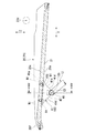
図1、図2に示すように、椅子1は、床面F上に載置される脚部10と、脚部10に支持された座部20と、座部20の後方に設けられた背凭れ部30と、を備えている。座部20は、着座面20aを上方に向けた使用位置P1から、前端側を上方に跳ね上げた跳ね上げ位置P2(図4参照)まで回動可能である。以下、椅子1における座部20を除いた集合体を、座部20を回動可能に支持する支持構造体10Aと称することがある。
Hereinafter, the chair according to the embodiment of the present invention will be described with reference to the accompanying drawings.
As shown in FIGS. 1 and 2, the chair 1 has a
以下の説明において、便宜上、椅子1の座部20上に着座した利用者(着座者)が前を向く方向を「前方」、その反対方向を「後方」、つまり図2に示す紙面に直交する方向を前後方向又は奥行方向と称する。さらに、椅子1を設置する床側とその反対側とを結ぶ方向を上下方向、椅子1の幅方向、つまり図2の紙面に沿った横方向を左右方向又は幅方向と称する。また、座部20の説明における前後方向および上下方向の向きは、特に記載がなければ使用位置P1にあるときの向きとする。なお、図中適所には、椅子1の幅方向を示す矢印X、椅子1の奥行方向を示す矢印Y、椅子1の上下方向を示す矢印Zが示されている。
In the following description, for convenience, the direction in which the user (seat person) seated on the
<脚部>
図1〜図3に示すように、脚部10は、左右一対で構成された脚フレーム11と、これら左右の脚フレーム11同士を連結する前フレーム12と、を一体に備えている。脚部10は、金属材料からなる管状の材料により形成されている。
<Legs>
As shown in FIGS. 1 to 3, the
左右の脚フレーム11は、前方に配設された前脚13と、後方に配設された後脚14と、前脚13の上部と後脚14の上部とを互いに連結する上部連結杆15と、を有している。
The left and right leg frames 11 include a
前脚13は、その下端から鉛直上方に延びる鉛直部13aと、鉛直部13aの上端で湾曲して後方に向けて斜め上方に延びる斜行部13bと、を有している。この前脚13の鉛直部13aの下端には、キャスター16が装着されている。
The
後脚14は、その下端から鉛直上方に延びる鉛直部14aと、鉛直部14aの上方で湾曲して前方に向けて斜め上方に延びる斜行部14bと、を有している。この後脚14の鉛直部14aの下端には、キャスター17が装着されている。
The
また、後脚14は、斜行部14bに連続し、上部連結杆15よりも上方へさらに斜め上方に延びる上方延出部18を一体に備えている。
また、上方延出部18の上下中間部には、前下方に向かって斜めに延び、座部20の後部を支持する座支持部19が設けられている。
Further, the
Further, in the upper and lower intermediate portions of the upward extending
上部連結杆15は、前脚13の斜行部13bの上端に連続して形成され、斜行部13bの上端で湾曲して後方に向かうにしたがって次第に上方に向かって延びるよう形成されている。上部連結杆15の後端15bは、後脚14の斜行部14bの上部に溶接、ロウ付け等により接合されている。
The upper connecting
前フレーム12は、左右の前脚13の斜行部13bの上端部から前方に向けて斜め上方に延びる左右一対の斜行部12aと、左右の斜行部12aの上端に連続して形成され、左右の斜行部12aの上端で湾曲して左右方向(水平方向)に延び、左右の斜行部12a同士を連結する水平フレーム部12bと、を一体に備えている。前フレーム12の左右斜行部12aの下端は、それぞれ左右の前脚13の斜行部13bの上端部に溶接またはロウ付け等により接合されている。
The
この前フレーム12により、左右の脚フレーム11は、その前部において互いに連結されている。この前フレーム12は、座部20に着座する利用者の体重が左右の前脚13に作用する際に、これら前脚13が左右方向外側に拡開することを防ぐ役割を担っている。
By the
このような脚部10において、左右の脚フレーム11の前脚13及び後脚14は、上方から下方に向かうにしたがって左右方向外側に向かうように形成されている。
また、左右の脚フレーム11において、左右の上部連結杆15は、その間隔が、それぞれの後端15bから前端15aに向けて漸次小さくなるよう設けられている。これにより、左右の前脚13は、左右の後脚14に対し、床面Fから同じ高さにおける左右方向の間隔が小さくなるように設けられている。
In such a
Further, in the left and right leg frames 11, the left and right upper connecting
<背凭れ部>
背凭れ部30は、例えば合板等の木製材料により形成されている。背凭れ部30は、板状で座部20に着座する利用者の背中を受ける背本体31を備えている。背本体31は、利用者の背中の湾曲に沿うように、上下方向から見て後方に凸の緩やかな湾曲形状をなしている。
<Backrest>
The
背本体31の左右方向両側の下部には、それぞれ左右の後脚14の上方延出部18の上部に支持される被支持部32が設けられている。上方延出部18の上部は、斜行部14bに直線的に連続する下部に対し、上方に向かうにしたがって次第に後方に傾斜するように傾斜している。左右の被支持部32は、例えば前面側から挿通した不図示のボルトを上方延出部18に螺着することで、上方延出部18に締結されている。図中符号32aは被支持部32のボルト挿通部を隠す遮蔽部材を示す。
At the lower portions on both sides of the
一体の背本体31の左右方向両側の被支持部32を、左右の上方延出部18に固定することによって、脚部10の左右の脚フレーム11の後脚14は、背本体31を介して互いに連結されている。
この背凭れ部30は、上部が上方に向かうにしたがって後方に傾斜するように形成されている。これにより、座部20に着座する利用者の背中をより安定的に支持することが可能とされている。
By fixing the supported
The
<座部>
座部20は、背凭れ部30と同様、例えば合板等の木製材料により形成されている。座部20は、板状で着座する利用者の臀部および大腿部を受ける座本体21と、座本体21の後部下面に沿うように左右方向に延びる座後支持部材22と、を備えている。座本体21の後部は、利用者の臀部の湾曲に沿うように、前後方向から見て下方に凸の緩やかな湾曲形状をなしている。座本体21の前部は、後部に比べて前後方向から見た湾曲は小さいが、前端部20fを前下がりに湾曲させて大腿部に対するエッジ感を抑えている。座本体21は、脚部10の左右の上部連結杆15および前フレーム12の上方を覆うように配設されている。
<Seat>
Like the
座後支持部材22は、座本体21の後部を下方から支持する。座後支持部材22は、例えば樹脂又は金属材料により形成されている。座後支持部材22は、左右方向に延在する延在部22aと、延在部22aの左右両端部から屈曲して上方に向けて延出する被支持部22bと、を備えている。延在部22aは、座本体21の後部下面に沿う板状をなしている。延在部22aの左右中間部の前側には、半円状の凹部22a1が形成されている。なお、座後支持部材22には、例えば合成樹脂製のカバーが装着されており、図中の座後支持部材22はカバーの外観を示している。また、座後支持部材22に連結される座支持部19にも同様に、例えば合成樹脂製のカバーが装着されており、図中の座支持部19はカバーの外観を示している。
The seat
左右の被支持部22bは、座本体21よりも上方に突出する側面視三角形状をなしている。左右の被支持部22bは、脚部10における左右の座支持部19に左右方向内側から重なるように配置されている。左右の被支持部22bの頂部には、それぞれ左右方向に沿う左右の回動軸22dを介して、左右の座支持部19が連結されている。左右の回動軸22dは、互いに同軸をなしている。座部20の後部は、脚部10に対し、左右方向に沿う左右の回動軸22dを介して回動可能に支持されている。そして、図4に示すように、座部20は、前端部20fを上方に跳ね上げ可能となっている。なお、図中の回動軸22dは中心軸線で示している。
The left and right supported
図1〜図3に示すように、座部20の前端部20fを使用位置P1に降ろした状態では、座本体21の下面21aに固定された座受け部材40の凹溝45(図6等参照)が、脚部10の前フレーム12の水平フレーム部12b上に外嵌するように載置、係合される。
As shown in FIGS. 1 to 3, when the
また、図4に示すように、座部20を上方に跳ね上げた状態では、複数の椅子1を、前後方向に重畳することができるようになっている。ここで、脚部10は、前方に向けて左右方向の幅が漸次小さくなっているので、前方の椅子1の脚部10の内側に、後方の椅子1の脚部10を挿入することで、複数の椅子1を前後方向に重畳することが可能となっている。
Further, as shown in FIG. 4, in a state where the
座部20の前端部20fは遊端部となる。座部20の前側領域Sfは、左右両端から左右方向内側に離間した部位が座受け部材40を介して脚部10に支持されている。座部20が合板等の木製材料により形成される場合、座部20を積極的に撓ませることはないが、座部20が合成樹脂により形成される場合、座部20を積極的に撓ませる構成としてもよい。その場合、例えば座部20の前側領域Sfの座受け部材40よりも左右方向外側の部位は、着座荷重を受けると、座本体21の撓みによって下方へ変位可能である。このため、座部20の前側領域Sfは、着座者の大腿部を柔軟に支持することができる。
The
<座受け部材>
図4、図5に示すように、座本体21における回動軸22dから前方に離間した前部の下面21aには、左右一対の座受け部材40が固定されている。
左右の座受け部材40は、それぞれ座本体21の下面21aから下方に向けて突出し、脚部10の前フレーム12の水平フレーム部12bの左右側部に上方から係合可能である。
<Seat support member>
As shown in FIGS. 4 and 5, a pair of left and right
The left and right
図6〜図9を参照し、座受け部材40は、座部20に固定されるとともに水平フレーム部12bに当接して着座荷重を水平フレーム部12bに伝達可能とする座受け本体41と、座受け本体41の内側に保持されて荷重受け面43から下方に突出するとともに上方からの荷重により弾性変形して荷重受け面43を水平フレーム部12bに当接可能とする弾性部材42と、を備えている。
With reference to FIGS. 6 to 9, the
図9を参照し、座受け本体41は、座本体21の下面21aに整合し当接する前後方向に長い長円状の上面41aを形成する基部41bと、基部41bの下方に側面視山形をなして突出する突出部41cと、を備えている。突出部41cは、座本体21の下面21aから下方に突出するように設けられている。
With reference to FIG. 9, the seat receiving
図6、図7を参照し、突出部41cの前後にそれぞれ形成された傾斜面41dは、側面視で凹状をなしている。前後の傾斜面41dには、座受け本体41の前部および後部を上面41aと直交するように貫通するボルト挿通孔41eが開口している。前後のボルト挿通孔41eに下方から挿通したボルトB1を、座本体21に予め埋設された雌ねじ部材N1に螺着することで、座受け本体41が座本体21に締結固定されている。
With reference to FIGS. 6 and 7, the
図8、図9を参照し、突出部41cは、基部41bに対して、下方ほど左右幅を狭めるように形成されている。突出部41cの左右側面41fは、前後方向から見て凹状に形成されている。突出部41cの頂部(下端部)には、側面視で上方に向けた凹状をなす凹溝45が形成されている。凹溝45は、水平フレーム部12bの長さ方向(左右方向)に垂直な断面視(図6、図7参照)で、丸パイプ状の水平フレーム部12bの外周面に整合するように、側面視で概略半円状に形成されている。
With reference to FIGS. 8 and 9, the protruding
詳細には、図9に示すように、凹溝45は、側面視略台形状に形成されている。凹溝45は、略水平をなして水平フレーム部12bの上端に当接可能な上端面45aと、上端面45aの前後端から前後下方に斜めに延びる前後の傾斜面45bと、を形成している。上端面45aは荷重受け面43であり、水平フレーム部12bの上端に当接することで、座部20に加わった着座荷重を水平フレーム部12bに伝達する。このとき、上端面45aは、水平フレーム部12bから着座荷重の反力を受ける。
Specifically, as shown in FIG. 9, the
前後の傾斜面45bは、平面状または凹状をなし、水平フレーム部12bの外周面との間に僅かな隙間を空けて対向する(図6、図7参照)。前後の傾斜面45bは、水平フレーム部12bに対して座部20が前後方向に変位したときには、水平フレーム部12bに当接して係止する係止面46である。以下、上端面45aおよび前後の傾斜面45bを合わせて、凹溝45の内周面45nと称することがある。
The front and rear
座受け本体41における凹溝45の前後方向の両側に位置する部位は、それぞれ下方に向けて突出する凸部47とされている。これら前後の凸部47は、水平フレーム部12bに前後の傾斜面45bを当接可能である。このように、座受け本体41の頂部には、着座荷重が入力される荷重受け面43が形成されるとともに、水平フレーム部12bに対して前後方向で係止可能な係止面46が形成されている。
The portions of the
図7、図8を参照し、座受け本体41は、内部空間K1を有する中空状をなしている。内部空間K1は、座受け本体41における前後の傾斜面41d、左右の側面41f、および凹溝45の内周面45n等の外面を形成する壁部に囲まれて形成されている。内部空間K1は、上面41aおよび凹溝45の内周面45nで開口している。
With reference to FIGS. 7 and 8, the seat receiving
座受け本体41の上面41aには、内部空間K1を開口させる上面開口部41a1が形成されている。上面開口部41a1は、座本体21の下面21aと対向し、下面21aによって閉塞されている。
An upper surface opening 41a1 for opening the internal space K1 is formed on the
図9を併せて参照し、凹溝45の内周面45nには、内部空間K1を開口させる内周開口部45n1が形成されている。内周開口部45n1は、前後方向では凹溝45の上端面45aから前後の傾斜面45bの中間位置に渡る範囲に形成されている。内周開口部45n1は、左右方向では凹溝45の内周面45nの左右方向内側に形成されている。内周開口部45n1からは、座受け本体41内に保持した弾性部材42の下端部が凹溝45内に突出している。
With reference to FIG. 9, an inner peripheral opening 45n1 for opening the internal space K1 is formed on the inner
弾性部材42は、例えば円柱状のゴム部材で形成されている。弾性部材42は、長さ方向(軸方向)を概ね前後方向に向けて配置されている。詳細には、弾性部材42は、長さ方向を座本体21の下面21aと略平行でかつ左右方向と直交させるように配置されている。図中符号C1は弾性部材42の長さ方向に沿う中心軸線を示す。凹溝45は、中心軸線(長さ方向)C2を左右方向に沿わせている。水平フレーム部12bも凹溝45と同様に、中心軸線(長さ方向)C3を左右方向に沿わせている。したがって、弾性部材42は、凹溝45および水平フレーム部12bに対して、長さ方向を直交させるように配置されている。
The
弾性部材42は、座受け本体41の内部空間K1で、座受け本体41の内壁面との間に隙間を空けて配置されており、荷重を受けた際の内部空間K1での弾性変形が良好である。
また、座受け本体41の内部には、弾性部材42を開口部45n1と反対側から支持する弾性部材支持部44が設けられている。これにより、弾性部材42が荷重を受けた際、弾性部材42が内部空間K1側から弾性部材支持部44によって支持されるので、弾性部材42の弾性変形が良好である。
さらに、座受け本体41の開口部45n1の左右両側には、開口部45n1の外側から弾性部材42に係止し、弾性部材42の開口部45n1からの脱落を防ぐ係止爪45n2が設けられている。
The
Further, inside the seat receiving
Further, on both left and right sides of the opening 45n1 of the
係る構成により、座部20が着座位置に向けて回動し、座受け部材40の弾性部材42が水平フレーム部12bに上方から当接すると、弾性部材42における凹溝45内側に突出した下端部の長さ方向の中間部が、水平フレーム部12bに当接して部分的に弾性変形する。このため、弾性部材42を全長に渡って弾性変形させる場合に比べて、弾性部材42の上下方向の弾性変形量を増やすことが可能となり、緩衝性能の設定自由度が高まる。
With this configuration, when the
ここで、座部20を跳ね上げ位置P2から使用位置P1に向けて回動させるとき、座部20を勢いよく回動させると、座受け部材40が水平フレーム部12bに衝突し、衝突音が発生したり衝撃荷重によって座受け部材40や周辺部品に破損や経年劣化を生じさせる虞がある。
Here, when the
これに対し、本実施形態によれば、左右一対の座受け部材40が水平フレーム部12bへの当接部(内周面45n)に弾性部材42を突出させているので、座体の回動により座受け部材40が水平フレーム部12bに衝突しても、弾性部材42によって緩衝がなされる。このため、座体をすばやく降ろしても、水平フレーム部12bとの衝突による衝突音や衝撃荷重の発生が抑えられる。したがって、座体回動時の衝突音を抑えて品質を高めるとともに、衝撃荷重の発生を抑えて耐久性にも優れた椅子1を提供することができる。
On the other hand, according to the present embodiment, since the pair of left and right
そして、利用者が座体に着座したときには、着座荷重の入力により弾性部材42が撓むので、座受け本体41の荷重受け面43が水平フレーム部12bに当接して着座荷重を受けることが可能となり、着座荷重を安定して支持することができる。
Then, when the user is seated on the seat, the
以上説明したように、本実施形態の椅子1は、着座面20aを形成する座部20と、前記座部20を椅子幅方向に沿う枢軸(回動軸22d)回りに回動可能に支持する支持構造体10Aと、を備え、前記座部20および支持構造体10Aの少なくとも一方は、前記座部20が着座面20aを上方に向けた使用位置P1にあるときに、前記座部20および支持構造体10Aの内の相手側の水平フレーム部12bに係合して着座荷重を受ける座受け部材40を備え、前記座受け部材40は、前記座部20が使用位置P1にあるときに前記水平フレーム部12bに当接可能な荷重受け面43を形成する座受け本体41と、前記座受け本体41に保持されるとともに少なくとも一部が前記荷重受け面43上に突出し、前記荷重受け面43に向けて荷重が付与されたときには弾性変形して前記荷重受け面43内に没入する弾性部材42と、を備えている。
As described above, the chair 1 of the present embodiment rotatably supports the
この構成によれば、座部20および支持構造体10Aの少なくとも一方の座受け部材40が、荷重受け面43に弾性部材42を突出させているので、座部20を着座位置に降ろしたときに座受け部材40が相手側の水平フレーム部12bに衝突しても、弾性部材42によって緩衝がなされる。このため、座部20をすばやく降ろした際の衝突音や衝撃荷重の発生を抑えることができる。また、使用位置P1に降ろした座部20に利用者が着座した際には、荷重受け面43への荷重入力によって弾性部材42が荷重受け面43内に没入するので、座受け本体41によって着座荷重を安定して支持することができる。
According to this configuration, at least one
本実施形態の椅子1において、前記座受け本体41は、内部空間K1を有する中空状とされ、前記弾性部材42は、少なくとも一部が前記座受け本体41の内部空間K1に配置され、前記荷重受け面43には、前記座受け本体41の内部空間K1を開放する開口部45n1が形成され、前記弾性部材42は、前記開口部45n1を通じて前記荷重受け面43上に突出している。
この場合、弾性部材42を中空の座受け本体41の内部空間K1に配置するとともに、荷重受け面43に開口部45n1を形成して弾性部材42を部分的に突出させるので、弾性部材42による緩衝を確実に行った上で荷重受け面43を水平フレーム部12bに当接させるとともに、荷重を受けた弾性部材42を座受け本体41の内部空間K1で弾性変形させることができる。
In the chair 1 of the present embodiment, the
In this case, since the
本実施形態の椅子1において、前記弾性部材42は、前記座受け本体41の内部空間K1で、前記座受け本体41の内壁面との間に隙間を空けて配置されている。
この場合、内部空間K1に収容した弾性部材42の十分な弾性変形を許容し、良好な緩衝性能を得ることができる。
In the chair 1 of the present embodiment, the
In this case, sufficient elastic deformation of the
本実施形態の椅子1において、前記座受け本体41の内部に、前記弾性部材42を前記開口部45n1と反対側から支持する弾性部材支持部44を備えている。
この場合、荷重受け面43に向けた荷重入力によって弾性部材42が受けた荷重を、開口部45n1と反対側から弾性部材支持部44によって支持するので、弾性部材42を安定して弾性変形させることができる。
In the chair 1 of the present embodiment, the elastic
In this case, the load received by the
本実施形態の椅子1において、前記座受け本体41は、前記弾性部材42に係止して前記開口部45n1からの脱落を防ぐ係止爪45n2を備えている。
この場合、内部空間K1内に収容した弾性部材42が開口部45n1から脱落することを防ぎ、弾性部材42を安定して保持することができる。
In the chair 1 of the present embodiment, the seat receiving
In this case, the
本実施形態の椅子1において、前記座受け本体41は、第一の方向(左右方向)に沿って延びる前記水平フレーム部12bに対し、前記水平フレーム部12bの前記第一の方向と交差する断面視で外嵌するように係合する凹溝45を有し、前記凹溝45は、凹状の内周面45nの底部(上端面45a)を前記荷重受け面43とし、前記荷重受け面43を前記第一の方向と交差する第二の方向(前後方向)で挟んだ両側に、前記第二の方向で前記水平フレーム部12bに係止可能な係止面46(傾斜面45b)を有している。
この場合、水平フレーム部12bの長さ方向(第一の方向)と交差する交差方向(第二の方向)において、座支持体の凹溝45が水平フレーム部12bに係止可能となるので、座支持体の水平フレーム部12bへの係合位置が前記交差方向でずれることを防ぎ、着座荷重を安定して支持することができる。なお、例えばフレーム部が前後方向に延び、荷重受け面の左右方向の両側に係止面を有する等、第一の方向および第二の方向は様々である。
In the chair 1 of the present embodiment, the
In this case, the
本実施形態の椅子1において、前記弾性部材42は、前記第二の方向を長さ方向として延びる形状をなしている。
この場合、弾性部材42が水平フレーム部12bと交差するように延びる形状をなしているので、弾性部材42と水平フレーム部12bとが互いに交差するように当接して弾性部材42を良好に弾性変形させる。このため、弾性部材42の弾性変形量を増加させ、緩衝性能の向上を図ることができる。
In the chair 1 of the present embodiment, the
In this case, since the
本実施形態の椅子1において、前記弾性部材42は、前記凹溝45内で前記荷重受け面43上に突出している。
この場合、弾性部材42が凹溝45よりも外側に突出することを防ぎ、座受け部材40をコンパクトに形成することができる。
In the chair 1 of the present embodiment, the
In this case, the
なお、本発明は上記実施形態に限られるものではなく、例えば、上記実施形態では、座部20および背凭れ部30を木製の本体で構成されるものとしたが、少なくとも一方が樹脂製、鋼板製等の本体を備えてもよい。また、本体とは別にフレーム体を備えてもよい。座部20に荷重受け部を配置したが、座部20および支持構造体10Aの少なくとも一方に荷重受け部を配置した構成でもよい。荷重受け部は座部20および支持構造体10Aに一体形成される構成でもよい。
The present invention is not limited to the above embodiment. For example, in the above embodiment, the
荷重受け部は、椅子の座体に使用するものに限らず、折り畳み式の背凭れや脚等に使用してもよい。また、椅子に限らずデスク、テーブルおよびキャビネット等の他の什器に使用してもよい。
すなわち、本発明は、外部荷重が入力される可動部材と、前記可動部材を接近離反可能に支持する支持構造体と、を備える什器の荷重受け構造であって、前記可動部材および支持構造体の少なくとも一方に、前記可動部材および支持構造体の内の相手側のフレーム部に係合して前記外部荷重を受ける荷重受け部を備え、前記荷重受け部は、前記フレーム部に当接可能な荷重受け面を形成する荷重支持体と、前記荷重支持体に保持されるとともに少なくとも一部が前記荷重受け面上に突出し、前記荷重受け面に向けて荷重が付与されたときには弾性変形して前記荷重受け面内に没入する弾性部材と、を備えていることを特徴とする荷重受け構造を提供する。
この構成によれば、荷重入力部材および支持構造体の少なくとも一方の荷重受け部が、荷重受け面に弾性部材を突出させているので、可動部材の支持構造体への接近時に荷重受け部が相手側のフレーム部に衝突しても、弾性部材によって緩衝がなされる。このため、可動部材をすばやく移動させた際の衝突音や衝撃荷重の発生を抑えることができる。また、荷重入力部材への外部荷重の入力時には、荷重受け面への荷重入力によって弾性部材が荷重受け面内に没入するので、荷重支持体によって外部荷重を安定して支持することができる。
そして、上記実施形態における構成は本発明の一例であり、当該発明の要旨を逸脱しない範囲で種々の変更が可能である。
The load receiving portion is not limited to the one used for the seat body of the chair, and may be used for a foldable backrest, legs, or the like. Further, it may be used not only for chairs but also for other fixtures such as desks, tables and cabinets.
That is, the present invention is a load receiving structure of a fixture including a movable member to which an external load is input and a support structure for supporting the movable member so as to be able to approach and separate from each other. At least one of the movable member and the support structure is provided with a load receiving portion that engages with a mating frame portion and receives the external load, and the load receiving portion is a load capable of contacting the frame portion. The load support that forms the receiving surface, and when the load is held by the load support and at least a part of the load is projected onto the load receiving surface and a load is applied toward the load receiving surface, the load is elastically deformed and the load is applied. Provided is a load receiving structure characterized by comprising an elastic member that immerses in the receiving surface.
According to this configuration, at least one load receiving portion of the load input member and the support structure projects the elastic member from the load receiving surface, so that the load receiving portion is opposed to the load receiving portion when the movable member approaches the support structure. Even if it collides with the frame portion on the side, it is buffered by the elastic member. Therefore, it is possible to suppress the generation of collision noise and impact load when the movable member is moved quickly. Further, when the external load is input to the load input member, the elastic member is immersed in the load receiving surface by the load input to the load receiving surface, so that the external load can be stably supported by the load support.
The configuration in the above embodiment is an example of the present invention, and various modifications can be made without departing from the gist of the present invention.
1 椅子(什器)
10A 支持構造体
12b 水平フレーム部(フレーム部)
20 座部(可動部材)
20a 着座面
22d 回動軸(枢軸)
40 座受け部材(荷重受け部)
41 座受け本体(荷重支持体)
42 弾性部材
43 荷重受け面
44 弾性部材支持部
45 凹溝
45n1 開口部
45n2 係止爪
46 係止面
K1 内部空間
P1 使用位置
1 Chair (furniture)
20 Seat (movable member)
40 Seat receiving member (load receiving part)
41 Seat support body (load support)
42 Elastic member 43
Claims (7)
前記座部を椅子幅方向に沿う枢軸回りに回動可能に支持する支持構造体と、を備える椅子において、
前記座部および支持構造体の少なくとも一方は、前記座部が着座面を上方に向けた使用位置にあるときに、前記座部および支持構造体の内の相手側のフレーム部に係合して着座荷重を受ける荷重受け部を備え、
前記荷重受け部は、
前記座部が使用位置にあるときに前記フレーム部に当接可能な荷重受け面を形成する荷重支持体と、
前記荷重支持体に保持されるとともに少なくとも一部が前記荷重受け面上に突出し、前記荷重受け面に向けて荷重が付与されたときには弾性変形して前記荷重受け面内に没入する弾性部材と、を備え、
前記荷重支持体は、第一の方向に沿って延びる前記フレーム部に対し、前記フレーム部の前記第一の方向と交差する断面視で外嵌するように係合する凹部を有し、
前記凹部は、凹状の内周面の底部を前記荷重受け面とし、前記荷重受け面を前記第一の方向と直交する第二の方向で挟んだ両側に、前記第二の方向で前記フレーム部に係止可能な係止面を有し、
前記弾性部材は、前記第二の方向を長さ方向として延びる形状をなしている椅子。 The seat that forms the seating surface and
In a chair including a support structure that rotatably supports the seat portion around a pivot along the width direction of the chair.
At least one of the seat and the support structure engages with the mating frame within the seat and the support structure when the seat is in a position of use with the seating surface facing upwards. Equipped with a load receiving part that receives a seating load
The load receiving portion is
A load support that forms a load receiving surface that can come into contact with the frame when the seat is in the used position.
An elastic member that is held by the load support and at least a part of it projects onto the load receiving surface, and elastically deforms and immerses in the load receiving surface when a load is applied toward the load receiving surface. equipped with a,
The load support has a recess that engages the frame portion extending along the first direction so as to fit outward in a cross-sectional view intersecting the first direction of the frame portion.
The concave portion has the bottom of the concave inner peripheral surface as the load receiving surface, and the frame portion in the second direction on both sides of the load receiving surface in a second direction orthogonal to the first direction. Has a locking surface that can be locked to
The elastic member is a chair having a shape extending with the second direction as a length direction.
前記弾性部材は、少なくとも一部が前記荷重支持体の内部空間に配置され、
前記荷重受け面には、前記荷重支持体の内部空間を開放する開口部が形成され、
前記弾性部材は、前記開口部を通じて前記荷重受け面上に突出していることを特徴とする請求項1に記載の椅子。 The load support has an internal space and is hollow.
At least a part of the elastic member is arranged in the internal space of the load support.
An opening is formed on the load receiving surface to open the internal space of the load support.
The chair according to claim 1, wherein the elastic member projects onto the load receiving surface through the opening.
前記可動部材を接近離反可能に支持する支持構造体と、を備える什器の荷重受け構造であって、
前記可動部材および支持構造体の少なくとも一方に、前記可動部材および支持構造体の内の相手側のフレーム部に係合して前記外部荷重を受ける荷重受け部を備え、
前記荷重受け部は、
前記フレーム部に当接可能な荷重受け面を形成する荷重支持体と、
前記荷重支持体に保持されるとともに少なくとも一部が前記荷重受け面上に突出し、前記荷重受け面に向けて荷重が付与されたときには弾性変形して前記荷重受け面内に没入する弾性部材と、を備え、
前記荷重支持体は、第一の方向に沿って延びる前記フレーム部に対し、前記フレーム部の前記第一の方向と交差する断面視で外嵌するように係合する凹部を有し、
前記凹部は、凹状の内周面の底部を前記荷重受け面とし、前記荷重受け面を前記第一の方向と直交する第二の方向で挟んだ両側に、前記第二の方向で前記フレーム部に係止可能な係止面を有し、
前記弾性部材は、前記第二の方向を長さ方向として延びる形状をなしていることを特徴とする荷重受け構造。 Movable members to which an external load is input and
It is a load receiving structure of a fixture including a support structure for supporting the movable member so as to be able to approach and separate.
At least one of the movable member and the support structure is provided with a load receiving portion that engages with a frame portion on the other side of the movable member and the support structure to receive the external load.
The load receiving portion is
A load support that forms a load receiving surface that can come into contact with the frame portion,
An elastic member that is held by the load support and at least a part of it projects onto the load receiving surface, and elastically deforms and immerses in the load receiving surface when a load is applied toward the load receiving surface. equipped with a,
The load support has a recess that engages the frame portion extending along the first direction so as to fit outward in a cross-sectional view intersecting the first direction of the frame portion.
The concave portion has the bottom of the concave inner peripheral surface as the load receiving surface, and the frame portion in the second direction on both sides of the load receiving surface in a second direction orthogonal to the first direction. Has a locking surface that can be locked to
The elastic member has a load receiving structure characterized in that it has a shape extending with the second direction as a length direction.
Priority Applications (1)
| Application Number | Priority Date | Filing Date | Title |
|---|---|---|---|
| JP2017212730A JP6955968B2 (en) | 2017-11-02 | 2017-11-02 | Chair and load receiving structure |
Applications Claiming Priority (1)
| Application Number | Priority Date | Filing Date | Title |
|---|---|---|---|
| JP2017212730A JP6955968B2 (en) | 2017-11-02 | 2017-11-02 | Chair and load receiving structure |
Publications (2)
| Publication Number | Publication Date |
|---|---|
| JP2019083881A JP2019083881A (en) | 2019-06-06 |
| JP6955968B2 true JP6955968B2 (en) | 2021-10-27 |
Family
ID=66761510
Family Applications (1)
| Application Number | Title | Priority Date | Filing Date |
|---|---|---|---|
| JP2017212730A Active JP6955968B2 (en) | 2017-11-02 | 2017-11-02 | Chair and load receiving structure |
Country Status (1)
| Country | Link |
|---|---|
| JP (1) | JP6955968B2 (en) |
-
2017
- 2017-11-02 JP JP2017212730A patent/JP6955968B2/en active Active
Also Published As
| Publication number | Publication date |
|---|---|
| JP2019083881A (en) | 2019-06-06 |
Similar Documents
| Publication | Publication Date | Title |
|---|---|---|
| JP6822318B2 (en) | Vehicle seat | |
| JP6955968B2 (en) | Chair and load receiving structure | |
| JP2013132402A (en) | Chair | |
| JP5567402B2 (en) | Chair | |
| JP7240024B2 (en) | chair | |
| JP6213370B2 (en) | Vehicle seat with sliding mechanism | |
| JP6279883B2 (en) | Mounting structure of the exterior member in the chair | |
| JP4255804B2 (en) | Chair | |
| JP6777281B2 (en) | Chair | |
| JP6987373B2 (en) | Chair | |
| KR200458497Y1 (en) | Backrest and chair having the same | |
| JP5414229B2 (en) | Seat legrest | |
| JP6483762B2 (en) | Chair backrest device & chair | |
| JP2022073406A (en) | Chair structure and chair | |
| JP6433055B2 (en) | Chair | |
| JP2022073407A (en) | Chair structure and chair | |
| JP6695219B2 (en) | Chair load support member and chair | |
| JP7395316B2 (en) | Chair | |
| JP6490378B2 (en) | Chair | |
| JP2021019771A (en) | Seat part of chair utilizable as carpet, and chair having the seat part | |
| JP7330857B2 (en) | Chair | |
| JP6739247B2 (en) | Fixture components and fixtures | |
| JP6452225B2 (en) | Seat member, chair | |
| JP4486465B2 (en) | Chair backrest mounting structure | |
| JP7486296B2 (en) | Seats and chairs |
Legal Events
| Date | Code | Title | Description |
|---|---|---|---|
| A621 | Written request for application examination |
Free format text: JAPANESE INTERMEDIATE CODE: A621 Effective date: 20200527 |
|
| A977 | Report on retrieval |
Free format text: JAPANESE INTERMEDIATE CODE: A971007 Effective date: 20210325 |
|
| A131 | Notification of reasons for refusal |
Free format text: JAPANESE INTERMEDIATE CODE: A131 Effective date: 20210420 |
|
| A521 | Written amendment |
Free format text: JAPANESE INTERMEDIATE CODE: A523 Effective date: 20210604 |
|
| TRDD | Decision of grant or rejection written | ||
| A01 | Written decision to grant a patent or to grant a registration (utility model) |
Free format text: JAPANESE INTERMEDIATE CODE: A01 Effective date: 20210928 |
|
| A61 | First payment of annual fees (during grant procedure) |
Free format text: JAPANESE INTERMEDIATE CODE: A61 Effective date: 20211004 |
|
| R150 | Certificate of patent or registration of utility model |
Ref document number: 6955968 Country of ref document: JP Free format text: JAPANESE INTERMEDIATE CODE: R150 |