JP6955893B2 - Evaluation jig for the height position detection unit of the laser processing device and evaluation method for the height position detection unit of the laser processing device - Google Patents
Evaluation jig for the height position detection unit of the laser processing device and evaluation method for the height position detection unit of the laser processing device Download PDFInfo
- Publication number
- JP6955893B2 JP6955893B2 JP2017086311A JP2017086311A JP6955893B2 JP 6955893 B2 JP6955893 B2 JP 6955893B2 JP 2017086311 A JP2017086311 A JP 2017086311A JP 2017086311 A JP2017086311 A JP 2017086311A JP 6955893 B2 JP6955893 B2 JP 6955893B2
- Authority
- JP
- Japan
- Prior art keywords
- height position
- detection unit
- position detection
- laser beam
- unit
- Prior art date
- Legal status (The legal status is an assumption and is not a legal conclusion. Google has not performed a legal analysis and makes no representation as to the accuracy of the status listed.)
- Active
Links
Images


Classifications
-
- B—PERFORMING OPERATIONS; TRANSPORTING
- B23—MACHINE TOOLS; METAL-WORKING NOT OTHERWISE PROVIDED FOR
- B23K—SOLDERING OR UNSOLDERING; WELDING; CLADDING OR PLATING BY SOLDERING OR WELDING; CUTTING BY APPLYING HEAT LOCALLY, e.g. FLAME CUTTING; WORKING BY LASER BEAM
- B23K26/00—Working by laser beam, e.g. welding, cutting or boring
- B23K26/02—Positioning or observing the workpiece, e.g. with respect to the point of impact; Aligning, aiming or focusing the laser beam
- B23K26/03—Observing, e.g. monitoring, the workpiece
-
- B—PERFORMING OPERATIONS; TRANSPORTING
- B23—MACHINE TOOLS; METAL-WORKING NOT OTHERWISE PROVIDED FOR
- B23K—SOLDERING OR UNSOLDERING; WELDING; CLADDING OR PLATING BY SOLDERING OR WELDING; CUTTING BY APPLYING HEAT LOCALLY, e.g. FLAME CUTTING; WORKING BY LASER BEAM
- B23K26/00—Working by laser beam, e.g. welding, cutting or boring
- B23K26/02—Positioning or observing the workpiece, e.g. with respect to the point of impact; Aligning, aiming or focusing the laser beam
- B23K26/04—Automatically aligning, aiming or focusing the laser beam, e.g. using the back-scattered light
-
- H—ELECTRICITY
- H01—ELECTRIC ELEMENTS
- H01L—SEMICONDUCTOR DEVICES NOT COVERED BY CLASS H10
- H01L21/00—Processes or apparatus adapted for the manufacture or treatment of semiconductor or solid state devices or of parts thereof
- H01L21/67—Apparatus specially adapted for handling semiconductor or electric solid state devices during manufacture or treatment thereof; Apparatus specially adapted for handling wafers during manufacture or treatment of semiconductor or electric solid state devices or components ; Apparatus not specifically provided for elsewhere
- H01L21/67005—Apparatus not specifically provided for elsewhere
- H01L21/67242—Apparatus for monitoring, sorting or marking
- H01L21/67259—Position monitoring, e.g. misposition detection or presence detection
-
- B—PERFORMING OPERATIONS; TRANSPORTING
- B23—MACHINE TOOLS; METAL-WORKING NOT OTHERWISE PROVIDED FOR
- B23K—SOLDERING OR UNSOLDERING; WELDING; CLADDING OR PLATING BY SOLDERING OR WELDING; CUTTING BY APPLYING HEAT LOCALLY, e.g. FLAME CUTTING; WORKING BY LASER BEAM
- B23K26/00—Working by laser beam, e.g. welding, cutting or boring
- B23K26/02—Positioning or observing the workpiece, e.g. with respect to the point of impact; Aligning, aiming or focusing the laser beam
- B23K26/04—Automatically aligning, aiming or focusing the laser beam, e.g. using the back-scattered light
- B23K26/046—Automatically focusing the laser beam
-
- B—PERFORMING OPERATIONS; TRANSPORTING
- B23—MACHINE TOOLS; METAL-WORKING NOT OTHERWISE PROVIDED FOR
- B23K—SOLDERING OR UNSOLDERING; WELDING; CLADDING OR PLATING BY SOLDERING OR WELDING; CUTTING BY APPLYING HEAT LOCALLY, e.g. FLAME CUTTING; WORKING BY LASER BEAM
- B23K26/00—Working by laser beam, e.g. welding, cutting or boring
- B23K26/08—Devices involving relative movement between laser beam and workpiece
- B23K26/083—Devices involving movement of the workpiece in at least one axial direction
-
- B—PERFORMING OPERATIONS; TRANSPORTING
- B23—MACHINE TOOLS; METAL-WORKING NOT OTHERWISE PROVIDED FOR
- B23K—SOLDERING OR UNSOLDERING; WELDING; CLADDING OR PLATING BY SOLDERING OR WELDING; CUTTING BY APPLYING HEAT LOCALLY, e.g. FLAME CUTTING; WORKING BY LASER BEAM
- B23K26/00—Working by laser beam, e.g. welding, cutting or boring
- B23K26/36—Removing material
- B23K26/38—Removing material by boring or cutting
-
- B—PERFORMING OPERATIONS; TRANSPORTING
- B23—MACHINE TOOLS; METAL-WORKING NOT OTHERWISE PROVIDED FOR
- B23K—SOLDERING OR UNSOLDERING; WELDING; CLADDING OR PLATING BY SOLDERING OR WELDING; CUTTING BY APPLYING HEAT LOCALLY, e.g. FLAME CUTTING; WORKING BY LASER BEAM
- B23K26/00—Working by laser beam, e.g. welding, cutting or boring
- B23K26/50—Working by transmitting the laser beam through or within the workpiece
- B23K26/53—Working by transmitting the laser beam through or within the workpiece for modifying or reforming the material inside the workpiece, e.g. for producing break initiation cracks
-
- B—PERFORMING OPERATIONS; TRANSPORTING
- B23—MACHINE TOOLS; METAL-WORKING NOT OTHERWISE PROVIDED FOR
- B23K—SOLDERING OR UNSOLDERING; WELDING; CLADDING OR PLATING BY SOLDERING OR WELDING; CUTTING BY APPLYING HEAT LOCALLY, e.g. FLAME CUTTING; WORKING BY LASER BEAM
- B23K26/00—Working by laser beam, e.g. welding, cutting or boring
- B23K26/70—Auxiliary operations or equipment
- B23K26/702—Auxiliary equipment
- B23K26/705—Beam measuring device
-
- G—PHYSICS
- G01—MEASURING; TESTING
- G01B—MEASURING LENGTH, THICKNESS OR SIMILAR LINEAR DIMENSIONS; MEASURING ANGLES; MEASURING AREAS; MEASURING IRREGULARITIES OF SURFACES OR CONTOURS
- G01B11/00—Measuring arrangements characterised by the use of optical techniques
- G01B11/02—Measuring arrangements characterised by the use of optical techniques for measuring length, width or thickness
- G01B11/06—Measuring arrangements characterised by the use of optical techniques for measuring length, width or thickness for measuring thickness ; e.g. of sheet material
- G01B11/0608—Height gauges
-
- G—PHYSICS
- G01—MEASURING; TESTING
- G01B—MEASURING LENGTH, THICKNESS OR SIMILAR LINEAR DIMENSIONS; MEASURING ANGLES; MEASURING AREAS; MEASURING IRREGULARITIES OF SURFACES OR CONTOURS
- G01B7/00—Measuring arrangements characterised by the use of electric or magnetic techniques
- G01B7/02—Measuring arrangements characterised by the use of electric or magnetic techniques for measuring length, width or thickness
-
- H—ELECTRICITY
- H01—ELECTRIC ELEMENTS
- H01L—SEMICONDUCTOR DEVICES NOT COVERED BY CLASS H10
- H01L21/00—Processes or apparatus adapted for the manufacture or treatment of semiconductor or solid state devices or of parts thereof
- H01L21/02—Manufacture or treatment of semiconductor devices or of parts thereof
-
- H—ELECTRICITY
- H01—ELECTRIC ELEMENTS
- H01L—SEMICONDUCTOR DEVICES NOT COVERED BY CLASS H10
- H01L21/00—Processes or apparatus adapted for the manufacture or treatment of semiconductor or solid state devices or of parts thereof
- H01L21/67—Apparatus specially adapted for handling semiconductor or electric solid state devices during manufacture or treatment thereof; Apparatus specially adapted for handling wafers during manufacture or treatment of semiconductor or electric solid state devices or components ; Apparatus not specifically provided for elsewhere
- H01L21/67005—Apparatus not specifically provided for elsewhere
- H01L21/67011—Apparatus for manufacture or treatment
- H01L21/67092—Apparatus for mechanical treatment
-
- B—PERFORMING OPERATIONS; TRANSPORTING
- B23—MACHINE TOOLS; METAL-WORKING NOT OTHERWISE PROVIDED FOR
- B23K—SOLDERING OR UNSOLDERING; WELDING; CLADDING OR PLATING BY SOLDERING OR WELDING; CUTTING BY APPLYING HEAT LOCALLY, e.g. FLAME CUTTING; WORKING BY LASER BEAM
- B23K2103/00—Materials to be soldered, welded or cut
- B23K2103/50—Inorganic material, e.g. metals, not provided for in B23K2103/02 – B23K2103/26
- B23K2103/56—Inorganic material, e.g. metals, not provided for in B23K2103/02 – B23K2103/26 semiconducting
Description
本発明は、レーザー加工装置の高さ位置検出ユニットの評価用治具及びレーザー加工装置の高さ位置検出ユニットの評価方法に関する。 The present invention relates to an evaluation jig for a height position detection unit of a laser processing apparatus and an evaluation method for a height position detection unit of a laser processing apparatus.
半導体デバイスやLED(Light Emitting Diode)デバイスが形成されたウエーハや各種板状被加工物を分割予定ラインに沿って加工する際に用いられるレーザー加工装置が知られている。レーザー加工装置は、被加工物に対して透過性を有する波長のレーザー光線を分割予定ラインに沿って照射し、被加工物の内部に改質層を形成し、改質層を破断基点として被加工物を複数のデバイスチップに分割する加工方法を実施する際に用いられる。この種のレーザー加工装置は、改質層を形成する際に、切削ブレードによる切削加工と異なり、切削水を使わず、切り代も非常に狭いという優位性があり、使用が広がっている。 A laser processing device used for processing a wafer on which a semiconductor device or an LED (Light Emitting Diode) device is formed or various plate-shaped workpieces along a planned division line is known. The laser machining apparatus irradiates the workpiece with a laser beam having a wavelength that is transparent to the workpiece along the planned division line, forms a modified layer inside the workpiece, and uses the modified layer as a fracture base point for machining. It is used when carrying out a processing method for dividing an object into a plurality of device chips. Unlike cutting with a cutting blade, this type of laser machining device has the advantage of not using cutting water and having a very narrow cutting allowance when forming a modified layer, and its use is widespread.
改質層は、被加工物の厚さ方向で一定の位置に形成されないと、改質層から外れた位置で破断されてしまったり、破断されないといった問題が発生する。そこで、分割予定ラインに沿って被加工物の高さを加工前に測定する高さ位置検出ユニットと、高さ位置検出ユニットの測定した結果に合わせてレーザー光線の集光点を調整できる集光点位置調整ユニットとを備えるレーザー加工装置が開発された(例えば、特許文献1参照)。このレーザー加工装置により、被加工物の厚さが面内でばらついていたとしても、被加工物の表面から所定の深さに改質層を形成する事が出来る。 If the modified layer is not formed at a fixed position in the thickness direction of the workpiece, there will be a problem that the modified layer is broken or not broken at a position deviated from the modified layer. Therefore, a height position detection unit that measures the height of the workpiece along the planned division line before machining, and a focusing point that can adjust the focusing point of the laser beam according to the measurement results of the height position detection unit. A laser processing apparatus including a position adjusting unit has been developed (see, for example, Patent Document 1). With this laser processing device, even if the thickness of the work piece varies in the plane, the modified layer can be formed at a predetermined depth from the surface of the work piece.
特許文献1に示されたレーザー加工装置は、被加工物の加工を実施する前に、高さ位置検出ユニットが正しく高さを検出できるかを評価する必要がある。このために、特許文献1に示されたレーザー加工装置は、予め高さ位置の情報(水平方向の位置と高さとの関係を示す情報)を把握している評価用板状物をチャックテーブルで固定し、チャックテーブルを加工送りしながら評価用板状物に検出用レーザー光線を照射して高さを測定する。測定して得られた高さの情報と、予め把握している高さ位置の情報とを照らし合わせ、これらに差がなければ高さ位置検出ユニットの検出精度が加工に適していると判定できる。しかしながら、この方法では、予め高さ位置を把握している評価用板状物が無いと、高さ位置検出ユニットの評価が出来ないという課題があった。
The laser machining apparatus shown in
本発明は、このような点に鑑みてなされたものであり、予め高さ位置が既知である評価用板状物を用いることなく、高さ位置検出ユニットの評価を行うことができるレーザー加工装置の高さ位置検出ユニットの評価用治具及びレーザー加工装置の高さ位置検出ユニットの評価方法を提供することを目的とする。 The present invention has been made in view of these points, and is a laser processing apparatus capable of evaluating a height position detection unit without using an evaluation plate-like object whose height position is known in advance. It is an object of the present invention to provide a jig for evaluating a height position detection unit of a laser processing apparatus and a method for evaluating a height position detection unit of a laser processing apparatus.
上述した課題を解決し、目的を達成するために、本発明のレーザー加工装置の高さ位置検出ユニットの評価用治具は、被加工物を保持面で保持するチャックテーブルと、被加工物に対して透過性を有する波長の加工用レーザー光線を該チャックテーブルに保持された被加工物に照射する発振器と加工用レーザー光線を集光する集光器を有するレーザー光線照射ユニットと、該加工用レーザー光線の集光点位置を変位させる集光点位置調整ユニットと、該チャックテーブルに保持された被加工物に検出用レーザー光線を該集光器を通して照射し、該被加工物の上面高さ位置を検出する高さ位置検出ユニットと、該高さ位置検出ユニットからの検出信号に基づいて該集光点位置調整ユニットを制御する制御ユニットと、を備えるレーザー加工装置の該高さ位置検出ユニットの評価用治具であって、該検出用レーザー光線が照射される被照射面と、該被照射面と交差する方向に該被照射面を移動させるアクチュエータと、該アクチュエータを支持し該保持面に載置される基台部と、該アクチュエータの移動を制御する制御部と、を備えることを特徴とする。 In order to solve the above-mentioned problems and achieve the object, the evaluation jig of the height position detection unit of the laser processing apparatus of the present invention includes a chuck table for holding the workpiece on the holding surface and the workpiece. On the other hand, a laser beam irradiation unit having an oscillator for irradiating a work piece held on the chuck table with a processing laser beam having a transmissive wavelength and a condenser for condensing the processing laser beam, and a collection of the processing laser beams. A height that detects the height position of the upper surface of the workpiece by irradiating the condensing point position adjusting unit that displaces the position of the light spot and the workpiece held on the chuck table with a laser beam for detection through the concentrator. A jig for evaluating the height position detection unit of a laser processing apparatus including a vertical position detection unit and a control unit that controls the condensing point position adjustment unit based on a detection signal from the height position detection unit. An irradiated surface to which the detection laser beam is irradiated, an actuator for moving the irradiated surface in a direction intersecting the irradiated surface, and a group that supports the actuator and is placed on the holding surface. It is characterized by including a base portion and a control unit that controls the movement of the actuator.
前記レーザー加工装置の高さ位置検出ユニットの評価用治具において、該アクチュエータは、ピエゾアクチュエータ又はボイスコイルモータでも良い。 In the evaluation jig of the height position detection unit of the laser processing apparatus, the actuator may be a piezo actuator or a voice coil motor.
本発明のレーザー加工装置の高さ位置検出ユニットの評価方法は、レーザー加工装置の高さ位置検出ユニットの評価方法であって、前記評価用治具を該レーザー加工装置のチャックテーブルの保持面に載置する載置ステップと、該評価用治具の該アクチュエータを制御し、該被照射面を所望の振幅で移動させる移動プログラムを設定するプログラム設定ステップと、該保持面に載置された該評価用治具の該被照射面に該レーザー加工装置の検出用レーザー光線を照射し、該移動プログラムによって所望の振幅で移動する該被照射面の高さ位置の変動を該レーザー加工装置の高さ位置検出ユニットで検出する高さ検出ステップと、該高さ検出ステップで検出された該高さ位置の変動と、該プログラム設定ステップで設定した該振幅とを比較し、該高さ位置検出ユニットが該被照射面の高さ位置を検出できたか否かを判定する比較判定ステップと、を備えることを特徴とする。 The evaluation method of the height position detection unit of the laser processing apparatus of the present invention is the evaluation method of the height position detection unit of the laser processing apparatus, and the evaluation jig is placed on the holding surface of the chuck table of the laser processing apparatus. A mounting step for mounting, a program setting step for setting a movement program for controlling the actuator of the evaluation jig and moving the irradiated surface with a desired amplitude, and the mounting on the holding surface. The irradiated surface of the evaluation jig is irradiated with a laser beam for detection of the laser processing device, and the height position of the irradiated surface that moves with a desired amplitude by the movement program is changed to the height of the laser processing device. The height position detection unit detects the height detection step, compares the fluctuation of the height position detected in the height detection step with the amplitude set in the program setting step, and the height position detection unit It is characterized by including a comparison determination step for determining whether or not the height position of the irradiated surface can be detected.
本願発明は、予め高さ位置が既知である評価用板状物を用いることなく、高さ位置検出ユニットの評価を行うことができるという効果を奏する。 The present invention has an effect that the height position detection unit can be evaluated without using an evaluation plate-like object whose height position is known in advance.
本発明を実施するための形態(実施形態)につき、図面を参照しつつ詳細に説明する。以下の実施形態に記載した内容により本発明が限定されるものではない。また、以下に記載した構成要素には、当業者が容易に想定できるもの、実質的に同一のものが含まれる。さらに、以下に記載した構成は適宜組み合わせることが可能である。また、本発明の要旨を逸脱しない範囲で構成の種々の省略、置換又は変更を行うことができる。 An embodiment (embodiment) for carrying out the present invention will be described in detail with reference to the drawings. The present invention is not limited to the contents described in the following embodiments. In addition, the components described below include those that can be easily assumed by those skilled in the art and those that are substantially the same. Further, the configurations described below can be combined as appropriate. In addition, various omissions, substitutions or changes of the configuration can be made without departing from the gist of the present invention.
〔実施形態1〕
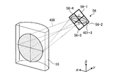
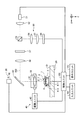
実施形態1に係るレーザー加工装置の高さ位置検出ユニットの評価用治具を説明する。図1は、実施形態1に係る高さ位置検出ユニットの評価用治具により評価されるレーザー加工装置の概略の構成例を示す斜視図である。図2は、図1に示すレーザー加工装置の加工対象のウエーハの斜視図である。図3は、図1に示されたレーザー加工装置の高さ位置検出ユニット等の構成を示す図である。図4は、図3に示す高さ位置検出ユニットが有する非点収差の説明図である。図5は、図3に示す高さ位置検出ユニットの光検出器における検出用レーザー光線のビームが縦長楕円形の場合を示す説明図である。図6は、図3に示す高さ位置検出ユニットの光検出器における検出用レーザー光線のビームが円形の場合を示す説明図である。図7は、図3に示す高さ位置検出ユニットの光検出器における検出用レーザー光線のビームが横長楕円形の場合を示す説明図である。
[Embodiment 1]
The jig for evaluating the height position detection unit of the laser processing apparatus according to the first embodiment will be described. FIG. 1 is a perspective view showing a schematic configuration example of a laser processing apparatus evaluated by the evaluation jig of the height position detection unit according to the first embodiment. FIG. 2 is a perspective view of a wafer to be processed by the laser processing apparatus shown in FIG. FIG. 3 is a diagram showing a configuration of a height position detection unit and the like of the laser processing apparatus shown in FIG. FIG. 4 is an explanatory diagram of astigmatism included in the height position detection unit shown in FIG. FIG. 5 is an explanatory diagram showing a case where the beam of the detection laser beam in the photodetector of the height position detection unit shown in FIG. 3 has a vertically elongated ellipse. FIG. 6 is an explanatory diagram showing a case where the beam of the detection laser beam in the photodetector of the height position detection unit shown in FIG. 3 is circular. FIG. 7 is an explanatory view showing a case where the beam of the detection laser beam in the photodetector of the height position detection unit shown in FIG. 3 has a horizontally long ellipse.
実施形態1に係る高さ位置検出ユニットの評価用治具1は、図1に示すレーザー加工装置10の図3に示す高さ位置検出ユニット50を評価するための治具である。図1に示すレーザー加工装置10は、被加工物である図2に示すウエーハ201の分割予定ライン202に図3に示す改質層203を形成する装置である。
The
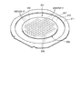
実施形態1に係るレーザー加工装置10の加工対象であるウエーハ201は、実施形態1ではシリコン、サファイア、ガリウムヒ素などを基板204とする円板状の半導体ウエーハや光デバイスウエーハである。ウエーハ201は、図2に示すように、表面205の交差(実施形態1では、直交)する複数の分割予定ライン202によって区画された複数の領域にそれぞれデバイス206が形成されている。
The
ウエーハ201は、デバイス206として、IC(Integrated Circuit)又はLSI(Large Scale Integration)などの半導体デバイスやLED(Light Emitting Diode)デバイスが各領域に形成される。分割予定ライン202は、互いに平行な複数の第1分割予定ライン202−1と、第1分割予定ライン202−1に直交する互いに平行な複数の第2分割予定ライン202−2とを備える。実施形態1において、ウエーハ201は、表面205に粘着テープ210が貼着され、粘着テープ210の外縁が環状フレーム211に貼着されることで、裏面207が露出した状態で環状フレーム211の開口に粘着テープ210で支持される。
In the
レーザー加工装置10は、ウエーハ201に対して透過性を有する波長の加工用レーザー光線300(図3に示す)をウエーハ201の裏面207側から分割予定ライン202−1,202−2に沿って照射し、加工用レーザー光線300でウエーハ201の内部に破断起点となる改質層203を形成するものである。なお、改質層203とは、密度、屈折率、機械的強度やその他の物理的特性が周囲のそれとは異なる状態になった領域のことを意味し、溶融処理領域、クラック領域、絶縁破壊領域、屈折率変化領域、及びこれらの領域が混在した領域等を例示できる。
The
レーザー加工装置10は、図1に示すように、ウエーハ201を保持面21で保持するチャックテーブル20と、レーザー光線照射ユニット30と、図3に示す集光点位置調整ユニット40と、図3に示す高さ位置検出ユニット50とを備える。また、レーザー加工装置10は、チャックテーブル20とレーザー光線照射ユニット30とをX軸方向に相対移動させるX軸移動ユニット60と、チャックテーブル20とレーザー光線照射ユニット30とをY軸方向に相対移動させるY軸移動ユニット70と、撮像ユニット80と、制御ユニット100とを備える。
As shown in FIG. 1, the
チャックテーブル20は、ウエーハ201を保持する保持面21を有する。保持面21は、粘着テープ210を介して環状フレーム211の開口に貼着されたウエーハ201を保持する。保持面21は、ポーラスセラミック等から形成された円盤形状であり、図示しない真空吸引経路を介して図示しない真空吸引源と接続されている。保持面21は、載置されたウエーハ201を、粘着テープ210を介して吸引し保持する。実施形態1では、保持面21は、X軸方向及びY軸方向と平行な平面である。チャックテーブル20の周囲には、ウエーハ201の周囲の環状フレーム211を挟持するクランプ部22が複数配置されている。また、チャックテーブル20は、回転ユニット23によりZ軸方向と平行な中心軸線回りに回転させる。回転ユニット23は、X軸移動ユニット60によりX軸方向に移動される移動テーブル24上に配置されている。
The chuck table 20 has a holding
X軸移動ユニット60は、チャックテーブル20をX軸方向に移動させることで、チャックテーブル20をX軸方向に加工送りする加工送り手段である。X軸移動ユニット60は、軸心回りに回転自在に設けられたボールねじ61と、ボールねじ61を軸心回りに回転させるパルスモータ62と、チャックテーブル20をX軸方向に移動自在に支持するガイドレール63とを備える。
The
Y軸移動ユニット70は、チャックテーブル20をY軸方向に移動させることで、チャックテーブル20を割り出し送りする割り出し送り手段である。Y軸移動ユニット70は、軸心回りに回転自在に設けられたボールねじ71と、ボールねじ71を軸心回りに回転させるパルスモータ72と、チャックテーブル20をY軸方向に移動自在に支持するガイドレール73とを備える。
The Y-
レーザー光線照射ユニット30は、ウエーハ201が透過性を有する波長の加工用レーザー光線300をチャックテーブル20に保持されたウエーハ201に裏面207側から照射するユニットである。レーザー光線照射ユニット30は、加工用レーザー光線300でウエーハ201の内部に改質層203を形成するユニットである。
The laser
レーザー光線照射ユニット30は、図1に示す加工ヘッド31と、図3に示す発振器32と、集光器である集光レンズ33とを備える。加工ヘッド31は、レーザー加工装置10の装置本体11から立設した壁部12に連なった支持柱13の先端に取り付けられている。
The laser
発振器32は、加工用レーザー光線300を発振し、発振した加工用レーザー光線300をダイクロイックミラー59を介して、加工ヘッド31の先端からチャックテーブル20に保持されたウエーハ201に照射する。ダイクロイックミラー59は、発振器32と集光レンズ33との間における加工用レーザー光線300の光路上に配置されている。ダイクロイックミラー59は、加工用レーザー光線300を透過する。発振器32が発振する加工用レーザー光線300は、例えば、YAGレーザー光線またはYVOレーザー光線である。実施形態1において、加工用レーザー光線300の波長は、例えば、1064nmであるが、これに限定されない。集光レンズ33は、加工用レーザー光線300をウエーハ201の内部に集光するものである。
The
集光点位置調整ユニット40は、加工用レーザー光線300の集光点301の位置をZ軸方向に変位させるものである。集光点位置調整ユニット40は、集光レンズ33を保持するレンズホルダ41と、レンズホルダ41をZ軸方向に移動させる駆動ユニット42とを備える。駆動ユニット42は、周知のボールねじやパルスモータ、ピエゾモータにより構成される。
The condensing point
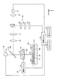
高さ位置検出ユニット50は、チャックテーブル20に保持されたウエーハ201に図3に示す検出用レーザー光線400を集光レンズ33を通して照射し、チャックテーブル20に保持されたウエーハ201の上面である裏面207の高さ位置であるZ軸方向の位置を検出するものである。なお、本発明では、Z軸方向の位置は、保持面21を基準(0μm)としている。高さ位置検出ユニット50は、検出用発振器51と、コリメートレンズ52と、偏光ビームスプリッター53と、凸レンズ54と、シリンドリカルレンズ55と、光検出器56と、λ/4板57と、凸レンズ58とを有する。
The height
検出用発振器51は、例えばレーザーダイオードから構成され、所定の波長の検出用レーザー光線400を発振し、検出用レーザー光線400をコリメートレンズ52と偏光ビームスプリッター53とλ/4板57と凸レンズ58とに順に通してダイクロイックミラー59に照射する。光検出器56は、図5、図6及び図7に示すように、分割領域56−1,56−2,56−3,56−4を4つ備えるフォトダイオードから構成される。検出用発振器51から照射された検出用レーザー光線400は、コリメートレンズ52により平行光に変換された後、偏光ビームスプリッター53、及びλ/4板57を透過し、ダイクロイックミラー59で反射される。ダイクロイックミラー59で反射された検出用レーザー光線400は、集光レンズ33を介して保持面21上のウエーハ201の裏面207に照射される。
The
ウエーハ201の裏面207で反射された検出用レーザー光線400は、ダイクロイックミラー59で反射され、凸レンズ58を透過してλ/4板57に入射する。ここで、ウエーハ201の裏面207で反射された検出用レーザー光線400は、ウエーハ201に向かう往路と該ウエーハ201で反射された復路とでλ/4板57を2回通過しているため、その偏光方向が90°回転する。このため、ウエーハ201の裏面207で反射された検出用レーザー光線400は、偏光ビームスプリッター53において反射され、凸レンズ54により集光されてシリンドリカルレンズ55に入射する。
The
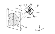
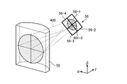
シリンドリカルレンズ55は、図4に示すように、円柱を軸方向に沿って半分にした略半円柱状を呈する。シリンドリカルレンズ55は、例えば、α方向のみにレンズ効果を有し、β方向においてはレンズ効果を有しない。すなわち、ウエーハ201の裏面207で反射された検出用レーザー光線400は、シリンドリカルレンズ55を通過する際、α方向の焦点位置とβ方向の焦点位置がずれて非点収差が発生した状態で光検出器56に入射する(図5、図6及び図7参照)。
As shown in FIG. 4, the
シリンドリカルレンズ55を透過した検出用レーザー光線400は、図4、図5、図6及び図7に示すように、ビーム401−1,401−2,401−3の平面形状が光軸上の位置によって縦長楕円形、円形、横長楕円形の順に変化する。このため、4分割フォトダイオードからなる光検出器56でビーム401−1,401−2,402−3を受光すると、ビーム401−1,401−2,402−3の平面形状に応じて各分割領域56−1,56−2,56−3,56−4に入射する光量のバランスが変化する。
As shown in FIGS. 4, 5, 6 and 7, the
図5に示すように、ビーム401−1が縦長楕円形の場合、光検出器56における分割領域56−1及び56−3の入射光量が分割領域56−2及び56−4の入射光量よりも大きくなる。また、図6に示すように、ビーム401−2が円形の場合、光検出器56における分割領域56−1,56−2,56−3,56−4の入射光量が等しくなる。また、図7に示すように、ビーム401−3が横長楕円形の場合、光検出器56における分割領域56−2及び56−4の入射光量が分割領域56−1及び56−3の入射光量よりも大きくなる。
As shown in FIG. 5, when the beam 401-1 has a vertically long elliptical shape, the incident light amount of the divided regions 56-1 and 56-3 in the
光検出器56は、分割領域56−1,56−2,56−3,56−4で検出した入射光量を制御ユニット100に出力する。制御ユニット100は、分割領域56−1及び分割領域56−3の入射光量の和と、分割領域56−2及び分割領域56−4の入射光量の和との差分値を算出する。
The
図5に示したビーム401−1が縦長楕円形の場合、上記の差分値は正(0よりも大きい)となる。図6に示したビーム401−2が円形の場合、差分値は0(ゼロ)となる。図7に示したビーム401−3が横長楕円形の場合、差分値は負(0よりも小さい)となる。 When the beam 401-1 shown in FIG. 5 has a vertically elongated ellipse, the above difference value is positive (greater than 0). When the beam 401-2 shown in FIG. 6 is circular, the difference value is 0 (zero). When the beam 401-3 shown in FIG. 7 has a horizontally long ellipse, the difference value is negative (smaller than 0).
実施形態1において、高さ位置検出ユニット50は、分割領域56−1,56−2,56−3,56−4で検出した入射光量を制御ユニット100に出力する。
In the first embodiment, the height
撮像ユニット80は、チャックテーブル20に保持されたウエーハ201を撮像するものであり、レーザー光線照射ユニット30とX軸方向に並列する位置に配設されている。実施形態1では、撮像ユニット80は、支持柱13の先端に取り付けられている。撮像ユニット80は、チャックテーブル20に保持されたウエーハ201を撮像するCCD(Charge Coupled Device)カメラや赤外線カメラにより構成される。
The
制御ユニット100は、レーザー加工装置10の構成要素をそれぞれ制御して、ウエーハ201に改質層203を形成する動作をレーザー加工装置10に実施させるものである。制御ユニット100は、コンピュータである。制御ユニット100は、CPU(Central Processing Unit)のようなマイクロプロセッサを有する演算処理装置と、ROM(Read Only Memory)又はRAM(Random Access Memory)のようなメモリを有する記憶装置と、入出力インターフェース装置とを有する。
The
制御ユニット100の演算処理装置は、記憶装置に記憶されているコンピュータプログラムに従って演算処理を実施して、レーザー加工装置10を制御するための制御信号を入出力インターフェース装置を介してレーザー加工装置10の上述した構成要素に出力する。また、制御ユニット100は、加工動作の状態や画像などを表示する液晶表示装置などにより構成される表示ユニット101や、オペレータが加工内容情報などを登録する際に用いる入力ユニット102と接続されている。入力ユニット102は、表示ユニット101に設けられたタッチパネルと、キーボード等とのうち少なくとも一つにより構成される。また、実施形態1において、制御ユニット100は、レーザー加工装置の高さ位置検出ユニットの評価用治具1も構成する。
The arithmetic processing unit of the
また、制御ユニット100は、分割領域56−1,56−2,56−3,56−4で検出した入射光量から前述した差分値を算出し、算出した差分値に基づいて、集光レンズ33とウエーハ201の裏面207とのZ軸方向の距離、即ちウエーハ201の裏面207のZ軸方向の位置を算出する。なお、実施形態1において、集光レンズ33による加工用レーザー光線300の集光点301の位置と、集光レンズ33による検出用レーザー光線400の集光点の位置とは互いに異なる。
Further, the
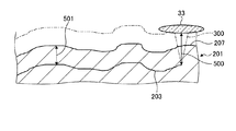
次に、レーザー加工装置10の加工動作を図面に基いて説明する。図8は、図1に示すレーザー加工装置の加工動作中の集光レンズとウエーハの裏面との位置関係を示す説明図である。
Next, the machining operation of the
レーザー加工装置10は、オペレータが加工内容情報を制御ユニット100に登録し、オペレータがウエーハ201をチャックテーブル20の保持面21に載置し、オペレータから加工動作の開始指示があった場合に、加工動作を開始する。加工動作では、レーザー加工装置10の制御ユニット100は、真空吸引源を駆動して、保持面21にウエーハ201を吸引保持する。
In the
加工動作では、レーザー加工装置10の制御ユニット100は、撮像ユニット80が撮像したウエーハ201の画像に基いてアライメントを実行し、回転ユニット23に複数の第1分割予定ライン202−1をX軸方向と平行にした後、複数の第1分割予定ライン202−1のうち予め定められた一つの第1分割予定ライン202−1の一端とレーザー光線照射ユニット30の加工ヘッド31とをZ軸方向に相対させる。レーザー加工装置10の制御ユニット100は、X軸移動ユニット60にチャックテーブル20をX軸方向に移動させながら高さ位置検出ユニット50の検出用発振器51から検出用レーザー光線400を発振させて、検出用レーザー光線400を一つの第1分割予定ライン202−1の一端から他端に向けて順に照射させる。レーザー加工装置10の制御ユニット100は、高さ位置検出ユニット50の光検出器56の検出信号に基づいて、一つの第1分割予定ライン202−1の一端から他端にかけてのウエーハ201の裏面207のZ軸方向の位置を算出し、記憶する。
In the processing operation, the
レーザー加工装置10の制御ユニット100は、回転ユニット23に複数の第2分割予定ライン202−2をX軸方向と平行にした後、複数の第2分割予定ライン202−2のうち予め定められた一つの第2分割予定ライン202−2の一端とレーザー光線照射ユニット30の加工ヘッド31とをZ軸方向に相対させる。レーザー加工装置10の制御ユニット100は、X軸移動ユニット60にチャックテーブル20をX軸方向に移動させながら高さ位置検出ユニット50の検出用発振器51から検出用レーザー光線400を発振させて、検出用レーザー光線400を一つの第2分割予定ライン202−2の一端から他端に向けて順に照射させる。レーザー加工装置10の制御ユニット100は、高さ位置検出ユニット50の光検出器56の検出信号に基づいて、一つの第2分割予定ライン202−2の一端から他端にかけてのウエーハ201の裏面207のZ軸方向の位置を算出し、記憶する。なお、高さ位置検出ユニット50が裏面207のZ軸方向の位置を検出する分割予定ライン202−1,202−2は、ウエーハ201の裏面207の中心を通るものが望ましく、又は、ウエーハ201の裏面207の中心により近いものが望ましい。
The
レーザー加工装置10の制御ユニット100は、複数の分割予定ライン202−1,202−2の全長に亘って加工用レーザー光線300を照射してウエーハ201の内部に改質層203を形成する。レーザー加工装置10の制御ユニット100は、加工用レーザー光線300を照射する際には、高さ位置検出ユニット50の検出信号から算出された分割予定ライン202−1,202−2の一端から他端にかけてのウエーハ201の裏面207のZ軸方向の位置に基づいて、裏面207と集光レンズ33との距離が、図8に示すように、ウエーハ201の内部に改質層203を形成する位置に基づいて定められた距離500で一定となるように、集光点位置調整ユニット40を制御する。すると、図8に示すように、改質層203の裏面207からの距離501は、分割予定ライン202−1,202−2の全長に亘って一定になる。なお、図8は、集光レンズ33の軌跡を一点鎖線で示しているとともに、裏面207の高さの変化を実際よりも誇張して示している。レーザー加工装置10の制御ユニット100は、全ての分割予定ライン202−1,202−2に沿って、ウエーハ201の内部に改質層203を形成すると、加工動作を終了する。
The
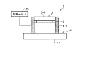
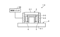
次に、実施形態1に係るレーザー加工装置の高さ位置検出ユニットの評価用治具1を図面に基いて説明する。図9は、実施形態1に係る高さ位置検出ユニットの評価用治具の構成を示す断面図である。図10は、図9に示す高さ位置検出ユニットの評価用治具の被照射面が上昇した状態を示す断面図である。図11は、図9に示す高さ位置検出ユニットの評価用治具の制御部が設定する移動プログラムの一例を示す説明図である。
Next, the
レーザー加工装置の高さ位置検出ユニットの評価用治具1(以下、単に評価用治具と記す)は、レーザー加工装置10の高さ位置検出ユニット50のウエーハ201の裏面207の位置の検出精度を評価するための治具である。評価用治具1は、図9及び図10に示すように、被照射部材2と、前述した制御ユニット100とを備えるアクチュエータ3と、基台部4とを備える。
The
被照射部材2は、基台部4にZ軸方向に移動自在に設けられ、かつ基台部4がチャックテーブル20の保持面21上に載置されると、レーザー光線照射ユニット30の加工ヘッド31に対向する。被照射部材2は、基台部4がチャックテーブル20の保持面21上に載置されると、X軸方向とY軸方向との双方と平行でかつ加工ヘッド31と対向する被照射面2−1を備える。被照射面2−1は、高さ位置検出ユニット50の検出用発振器51が発振した検出用レーザー光線400が照射される。
The
アクチュエータ3は、基台部4内に収容され、被照射面2−1と交差する方向であるZ軸方向に被照射面2−1を移動させるものである。実施形態1において、アクチュエータ3は、被照射部材2に取り付けられている。アクチュエータ3は、圧電体を2枚の電極で挟んで構成された所謂ピエゾアクチュエータであり、電極に電力が印加されることで、図9及び図10に示すように、被照射面2−1をZ軸方向に移動させる。なお、実施形態1において、アクチュエータ3は、ピエゾアクチュエータであるが、これに限定されない。
The
基台部4は、アクチュエータ3を支持しチャックテーブル20の保持面21に載置されるものである。基台部4は、平板状で形成されかつチャックテーブル20の保持面21に載置される平板部4−1と、平板部4−1から立設した円筒状に形成された円筒部4−2とを備える。基台部4は、円筒部4−2内にアクチュエータ3を収容しかつ平板部4−1上にアクチュエータ3を支持する。
The base portion 4 supports the
制御ユニット100は、アクチュエータ3を制御する。制御ユニット100は、図1に示すように、記憶部110と、制御部120とを備える。記憶部110は、移動プログラム設定プログラム111を記憶している。移動プログラム設定プログラム111は、高さ位置検出ユニット50を評価する際に、アクチュエータ3を制御し、被照射面2−1を図11に示す所望の振幅600でZ軸方向に移動させて、被加工物であるウエーハ201の分割予定ライン202−1,202−2の裏面207の位置を模擬するための移動プログラム601を設定するためのプログラムである。なお、移動プログラム設定プログラム111は、高さ位置検出ユニット50を評価する際の被照射面2−1のZ軸方向の位置が、高さ位置検出ユニット50がウエーハ201の分割予定ライン202−1,202−2に検出用レーザー光線400を照射して検出すると想定されるZ軸方向の位置に等しくなるような移動プログラム601を設定するのが望ましい。
The
制御部120は、高さ位置検出ユニット50を評価する際には、入力ユニット102の操作によりオペレータから加工対象のウエーハ201の検出用レーザー光線400が照射される分割予定ライン202−1,202−2の全長及び検出用レーザー光線400を照射する際のチャックテーブル20の移動速度が入力される。制御部120は、高さ位置検出ユニット50を評価する際には、入力された分割予定ライン202−1,202−2の全長及び検出用レーザー光線400を照射する際のチャックテーブル20の移動速度に基づいて、移動プログラム設定プログラム111を実行して、例えば図11に示す移動プログラム601を設定する。実施形態1において、図11に示す移動プログラム601は、アクチュエータ3による被照射面2−1のZ軸方向の振幅600、被照射面2−1の移動回数、被照射面2−1の移動速度を含む。なお、図11の横軸は、高さ位置検出ユニット50の評価を行うために検出用レーザー光線400を照射開始してからの経過時間を示し、縦軸は、被照射面2−1のZ軸方向の位置を示している。
When the
即ち、制御部120は、高さ位置検出ユニット50を評価する際には、入力された分割予定ライン202−1,202−2の全長及び検出用レーザー光線400を照射する際のチャックテーブル20の移動速度に基づいて、移動プログラム設定プログラム111を実行して、アクチュエータ3による被照射面2−1のZ軸方向の振幅600、被照射面2−1の移動回数、被照射面2−1の移動速度を設定する。制御部120は、高さ位置検出ユニット50を評価する際には、設定した移動プログラム601通りにアクチュエータ3の移動を制御する。
That is, when evaluating the height
制御ユニット100の演算処理装置は、記憶装置に記憶されているコンピュータプログラムに従って演算処理を実施して、制御部120の機能を実現する。制御ユニット100の記憶装置は、記憶部110の機能を実現する。
The arithmetic processing unit of the
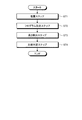
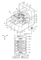
次に、実施形態1に係るレーザー加工装置の高さ位置検出ユニットの評価方法を図面に基いて説明する。図12は、実施形態1に係る高さ位置検出ユニットの評価方法を示すフローチャートである。図13は、図12に示す高さ位置検出ユニットの評価方法の載置ステップ及び高さ検出ステップを示す説明図である。図14は、図12に示す高さ位置検出ユニットの評価方法の比較判定ステップの判定結果の一例を示す説明図である。 Next, an evaluation method of the height position detection unit of the laser processing apparatus according to the first embodiment will be described with reference to the drawings. FIG. 12 is a flowchart showing an evaluation method of the height position detection unit according to the first embodiment. FIG. 13 is an explanatory diagram showing a mounting step and a height detection step of the evaluation method of the height position detection unit shown in FIG. FIG. 14 is an explanatory diagram showing an example of the determination result of the comparison determination step of the evaluation method of the height position detection unit shown in FIG.
実施形態1に係るレーザー加工装置の高さ位置検出ユニットの評価方法(以下、単に評価方法と記す)は、レーザー加工装置10の高さ位置検出ユニット50のウエーハ201の裏面207の位置の検出精度を評価する方法である。評価方法は、図12に示すように、載置ステップST1と、プログラム設定ステップST2と、高さ検出ステップST3と、比較判定ステップST4とを備える。
The evaluation method of the height position detection unit of the laser machining apparatus according to the first embodiment (hereinafter, simply referred to as an evaluation method) is the detection accuracy of the position of the
載置ステップST1は、評価用治具1をチャックテーブル20の保持面21に載置するステップである。実施形態1において、載置ステップでは、オペレータが、図13に示すように、レーザー加工装置10のチャックテーブル20の保持面21の中央に載置する。評価方法は、プログラム設定ステップST2に進む。
The mounting step ST1 is a step of mounting the
プログラム設定ステップST2は、評価用治具1のアクチュエータ3を制御し、被照射面2−1を所望の振幅600で移動させる移動プログラム601を設定するステップである。プログラム設定ステップST2では、オペレータが、入力ユニット102を操作して加工対象のウエーハ201の検出用レーザー光線400が照射される分割予定ライン202−1,202−2の全長及び検出用レーザー光線400を照射する際のチャックテーブル20の移動速度および被照射面2−1の所望の高さ位置を入力する。
The program setting step ST2 is a step of setting a
プログラム設定ステップST2では、制御ユニット100は、検出用レーザー光線400が照射される分割予定ライン202−1,202−2の全長及び検出用レーザー光線400を照射する際のチャックテーブル20の移動速度の入力を受け付けると、制御部120が、移動プログラム設定プログラム111を実行して、例えば、図11に示す移動プログラム601を設定する。実施形態1において、プログラム設定ステップST2で設定された図11に示す移動プログラム601は、振幅600を5μmとし、移動回数を1往復とし、移動速度を10μm/secとしている。評価方法は、高さ検出ステップST3に進む。
In the program setting step ST2, the
高さ検出ステップST3は、保持面21に載置された評価用治具1の被照射面2−1に検出用レーザー光線400を照射し、移動プログラム601によって所望の振幅600で移動する被照射面2−1の高さ位置であるZ軸方向の位置の変動を高さ位置検出ユニット50で検出するステップである。高さ検出ステップST3では、制御ユニット100は、オペレータからの評価開始指示を入力ユニット102などを介して受け付けると、X軸移動ユニット60及びY軸移動ユニット70を制御して、加工ヘッド31を被照射面2−1にZ軸方向に対向させる。そして、制御ユニット100は、図13に示すように、制御部120がプログラム設定ステップST2で算出した移動プログラム601を実行してアクチュエータ3を動作させるとともに、検出用レーザー光線400を被照射面2−1に照射する。すると、制御ユニット100は、高さ位置検出ユニット50の光検出器56の検出結果に基づいて、図14に示す一点鎖線で示すように被照射面2−1のZ軸方向の位置602を検出する。
In the height detection step ST3, the irradiated surface 2-1 of the
なお、図14の横軸は、高さ位置検出ユニット50の評価を行うために検出用レーザー光線400を照射開始してからの経過時間を示し、縦軸は、被照射面2−1のZ軸方向の位置を示している。また、図14の実線は、プログラム設定ステップST2で設定された移動プログラム601を示し、一点鎖線は、光検出器56の検出結果に基づいて算出された被照射面2−1のZ軸方向の位置602を示している。評価方法は、移動プログラム601の実行が終了すると、高さ検出ステップST3を終了して、比較判定ステップST4に進む。
The horizontal axis of FIG. 14 shows the elapsed time from the start of irradiation of the
比較判定ステップST4は、高さ検出ステップST3で検出された被照射面2−1の高さ位置であるZ軸方向の位置の変動と、プログラム設定ステップST2で設定した移動プログラム601の振幅600とを比較し、高さ位置検出ユニット50が被照射面2−1のZ軸方向の位置を検出できたか否かを判定するステップである。比較判定ステップST4は、制御ユニット100は、図14に示すように、プログラム設定ステップST2で設定された移動プログラム601と、高さ検出ステップST3で光検出器56の検出結果に基づいて算出された被照射面2−1のZ軸方向の位置602とを表示ユニット101に表示する。
In the comparison determination step ST4, the fluctuation of the position in the Z-axis direction, which is the height position of the irradiated surface 2-1 detected in the height detection step ST3, and the
実施形態1において、比較判定ステップST4では、オペレータが、プログラム設定ステップST2で設定された移動プログラム601と、高さ検出ステップST3で光検出器56の検出結果に基づいて算出された被照射面2−1のZ軸方向の位置602とを対比して、高さ位置検出ユニット50が被照射面2−1のZ軸方向の位置を検出できたか否かを判定する。具体的には、比較判定ステップST4では、オペレータが、プログラム設定ステップST2で設定された移動プログラム601と、高さ検出ステップST3で光検出器56の検出結果に基づいて算出された被照射面2−1のZ軸方向の位置602との最大の差603が予め定められた所定値を越えていると、高さ位置検出ユニット50が被照射面2−1の高さ位置を検出できていないと判定して、高さ位置検出ユニット50が不良であると判定する。
In the first embodiment, in the comparison determination step ST4, the operator calculates the
比較判定ステップST4では、オペレータが、プログラム設定ステップST2で設定された移動プログラム601と、高さ検出ステップST3で光検出器56の検出結果に基づいて算出された被照射面2−1のZ軸方向の位置602との最大の差603が予め定められた所定値以下であると、高さ位置検出ユニット50が被照射面2−1の高さ位置を検出できていると判定して、高さ位置検出ユニット50が良品であると判定する。なお、実施形態1において、比較判定ステップST4では、オペレータが、プログラム設定ステップST2で設定された移動プログラム601と、高さ検出ステップST3で光検出器56の検出結果に基づいて算出された被照射面2−1のZ軸方向の位置602との最大の差603に基づいて判定したが、本発明では、制御ユニット100の制御部120が同様に自動的に判定し、判定結果を表示ユニット101に表示しても良い。
In the comparison determination step ST4, the operator performs the Z-axis of the irradiated surface 2-1 calculated based on the
実施形態1に係る評価用治具1は、被照射面2−1をZ軸方向に移動するアクチュエータ3を備えているので、アクチュエータ3で被照射面2−1をZ軸方向に移動させることで、ウエーハ201の検出用レーザー光線400が照射される分割予定ライン202のZ軸方向の位置を被照射面2−1で模擬することができる。その結果、評価用治具1は、アクチュエータ3によって移動される被照射面2−1に検出用レーザー光線400が照射されることによって、予めZ軸方向の位置が既知である評価用板状物を用いることなく、高さ位置検出ユニット50の評価を行うことができる。
Since the
また、評価用治具1は、アクチュエータ3がピエゾアクチュエータであるので、微小な振幅600での被照射面2−1の移動を可能とすることができ、ウエーハ201の検出用レーザー光線400が照射される分割予定ライン202のZ軸方向の位置を被照射面2−1で模擬することができる。
Further, in the
実施形態1に係る評価方法は、プログラム設定ステップST2で設定した移動プログラム601通りにアクチュエータ3を制御して、被照射面2−1をZ軸方向に移動するので、ウエーハ201の検出用レーザー光線400が照射される分割予定ライン202のZ軸方向の位置を被照射面2−1で模擬することができる。その結果、評価方法は、高さ検出ステップST3において、アクチュエータ3によってZ軸方向に移動される被照射面2−1に検出用レーザー光線400を照射されることによって、予めZ軸方向の位置が既知である評価用板状物を用いることなく、高さ位置検出ユニット50の評価を行うことができる。
In the evaluation method according to the first embodiment, the
また、評価方法は、高さ検出ステップST3において、アクチュエータ3によってZ軸方向に移動される被照射面2−1に検出用レーザー光線400を照射されることによって、予めZ軸方向の位置が既知である評価用板状物を用いることなく、高さ位置検出ユニット50の評価を行うことができるので、チャックテーブル20をX軸方向に移動させることなく、高さ位置検出ユニット50の評価を行うことができる。その結果、評価方法は、チャックテーブル20のX軸方向に移動に伴う振動の影響を受けることなく、高さ位置検出ユニット50の評価を行うことができる。
Further, in the evaluation method, in the height detection step ST3, the position in the Z-axis direction is known in advance by irradiating the irradiated surface 2-1 moved in the Z-axis direction by the
〔実施形態2〕
実施形態2に係るレーザー加工装置の高さ位置検出ユニットの評価用治具1−2を説明する。図15は、実施形態2に係る高さ位置検出ユニットの評価用治具の構成を示す断面図である。図15は、実施形態1と同一部分に同一符号を付して説明を省略する。
[Embodiment 2]
The evaluation jig 1-2 of the height position detection unit of the laser processing apparatus according to the second embodiment will be described. FIG. 15 is a cross-sectional view showing the configuration of the evaluation jig of the height position detection unit according to the second embodiment. In FIG. 15, the same parts as those in the first embodiment are designated by the same reference numerals, and the description thereof will be omitted.
実施形態2に係るレーザー加工装置の高さ位置検出ユニットの評価用治具1−2(以下、単に評価用治具と記す)は、アクチュエータ3−2が実施形態1と異なる以外、実施形態1と同じ構成である。 The evaluation jig 1-2 (hereinafter, simply referred to as an evaluation jig) of the height position detection unit of the laser processing apparatus according to the second embodiment is the first embodiment except that the actuator 3-2 is different from the first embodiment. It has the same configuration as.
評価用治具1−2のアクチュエータ3−2は、図15に示すように、基台部4の円筒部4−2の内周面に取り付けられた円筒状の永久磁石5と、被照射部材2の円柱部の外周面に取り付けられたコイル6とを備える所謂ボイスコイルモータである。アクチュエータ3−2は、コイル6に電力が印加されることで、被照射面2−1をZ軸方向に移動させる。なお、実施形態2において、アクチュエータ3−2は、ボイスコイルモータであるが、これに限定されない。
As shown in FIG. 15, the actuator 3-2 of the evaluation jig 1-2 includes a cylindrical
実施形態2に係る評価用治具1−2は、実施形態1と同様に、被照射面2−1をZ軸方向に移動するアクチュエータ3−2を備えているので、アクチュエータ3−2によって移動される被照射面2−1に検出用レーザー光線400が照射されることによって、予めZ軸方向の位置が既知である評価用板状物を用いることなく、高さ位置検出ユニット50の評価を行うことができる。
Since the evaluation jig 1-2 according to the second embodiment includes the actuator 3-2 that moves the irradiated surface 2-1 in the Z-axis direction as in the first embodiment, the evaluation jig 1-2 is moved by the actuator 3-2. By irradiating the irradiated surface 2-1 to be irradiated with the
〔実施形態3〕
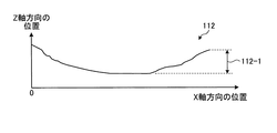
実施形態3に係るレーザー加工装置の高さ位置検出ユニットの評価用治具1を説明する。図16は、実施形態3に係る高さ位置検出ユニットの評価用治具の構成を示す説明図である。図17は、図16に示す高さ位置検出ユニットの評価用治具の制御ユニットの記憶部が記憶した高さパターンの一例を示す説明図である。図18は、図16に示す高さ位置検出ユニットの評価用治具の制御ユニットの記憶部が記憶した高さパターンの他の例を示す説明図である。図19は、図16に示す高さ位置検出ユニットの評価用治具の制御ユニットの記憶部が記憶した高さパターンの更に他の一例を示す説明図である。図16から図19は、実施形態1と同一部分に同一符号を付して説明を省略する。
[Embodiment 3]
The
実施形態3に係るレーザー加工装置の高さ位置検出ユニットの評価用治具1(以下、単に評価用治具と記す)は、制御ユニット100−3の記憶部110−3が、図16に示すように、移動プログラム設定プログラム111の他に高さパターン112,113,114を記憶部110−3に記憶している以外、実施形態1の評価用治具1と構成が同じである。図17、図18及び図19に示す高さパターン112,113,114は、被加工物であるウエーハ201の検出用レーザー光線400が照射される分割予定ライン202−1,202−2の裏面207のZ軸方向の位置を示すものである。なお、図17、図18及び図19の横軸は、検出用レーザー光線400が照射される分割予定ライン202−1,202−2のX軸方向の位置を示し、縦軸は、検出用レーザー光線400が照射される分割予定ライン202−1,202−2の裏面207のZ軸方向の位置を示している。
The evaluation jig 1 (hereinafter, simply referred to as an evaluation jig) of the height position detection unit of the laser processing apparatus according to the third embodiment is shown in FIG. 16 by the storage unit 110-3 of the control unit 100-3. As described above, the configuration is the same as that of the
また、高さパターン112,113,114の被照射面2−1のZ軸方向の最も低い位置と最も高い位置とのZ軸方向の距離112−1,113−1,114−1は、移動プログラム601が含む振幅600と同程度であり、例えば、5μm程度である。なお、図17に示す高さパターン112は、中央部が外縁部よりも凹んだウエーハ201の検出用レーザー光線400が照射される分割予定ライン202−1,202−2の裏面207のZ軸方向の位置を示している。図18に示す高さパターン113は、裏面207に細かい凹凸が形成されたウエーハ201の検出用レーザー光線400が照射される分割予定ライン202−1,202−2の裏面207のZ軸方向の位置を示している。図19に示す高さパターン114は、中央部が外縁部よりも凹みかつ裏面207に細かい凹凸が形成されたウエーハ201の検出用レーザー光線400が照射される分割予定ライン202−1,202−2の裏面207のZ軸方向の位置を示している。
Further, the distance between the lowest position and the highest position in the Z-axis direction of the irradiated surface 2-1 of the
なお、実施形態3において、記憶部110−3は、高さパターン112,113,114を三つ記憶しているが、本発明おいて、記憶部110−3が記憶する高さパターン112,113,114は、三つに限定されない。また、図17、図18及び図19に示す高さパターン112,113,114は、複数のウエーハ201の検出用レーザー光線400が照射される分割予定ライン202の裏面207のZ軸方向の位置を測定して生成することができる。
In the third embodiment, the storage unit 110-3 stores three
実施形態3に係るレーザー加工装置の高さ位置検出ユニットの評価方法(以下、単に評価方法と記す)のプログラム設定ステップST2では、オペレータが、入力ユニット102を操作して高さパターン112,113,114のうちいずれかを選択する。プログラム設定ステップST2では、制御ユニット100−3は、検出用レーザー光線400が照射される分割予定ライン202−1,202−2の全長及び検出用レーザー光線400を照射する際のチャックテーブル20の移動速度の入力に加えて、選択された高さパターン112,113,114を受け付けると、制御部120が、移動プログラム設定プログラム111を実行して、移動プログラム601を設定する。
In the program setting step ST2 of the evaluation method of the height position detection unit of the laser processing apparatus according to the third embodiment (hereinafter, simply referred to as an evaluation method), the operator operates the
実施形態3の移動プログラム設定プログラム111は、検出用レーザー光線400が照射される分割予定ライン202−1,202−2の全長及び検出用レーザー光線400を照射する際のチャックテーブル20の移動速度に基づいて、被照射面2−1のZ軸方向の位置が選択された高さパターン112,113,114と等しくなるような移動プログラム601を設定するものである。このために、実施形態3に係る評価方法のプログラム設定ステップST2では、制御ユニット100−3の制御部120は、移動プログラム設定プログラム111を実行して、被照射面2−1のZ軸方向の位置が選択された高さパターン112,113,114と等しくなるような移動プログラム601を設定する。
The movement
実施形態3に係る評価用治具1及び評価方法は、実施形態1と同様に、被照射面2−1をZ軸方向に移動するアクチュエータ3を備えているので、アクチュエータ3によって移動される被照射面2−1に検出用レーザー光線400が照射されることによって、予めZ軸方向の位置が既知である評価用板状物を用いることなく、高さ位置検出ユニット50の評価を行うことができる。
Since the
また、実施形態3に係る評価用治具1及び評価方法は、複数のウエーハ201の検出用レーザー光線400が照射される分割予定ライン202の裏面207のZ軸方向の位置を測定して生成することができる高さパターン112,113,114に被照射面2−1のZ軸方向の位置が等しくなるような移動プログラム601を設定するので、被照射面2−1の位置を実際のウエーハ201に近付けることができる。
Further, the
なお、本発明は、上記実施形態に限定されるものではない。即ち、本発明の骨子を逸脱しない範囲で種々変形して実施することができる。なお、実施形態1から実施形態3において、評価用治具1,1−2の制御ユニット100,100−3がレーザー加工装置10の各構成要素の制御をおこなっているが、本発明は、評価用治具1,1−2の制御ユニット100,100−3を、レーザー加工装置10の各構成要素の制御をおこなう制御ユニットと別のもので構成しても良い。
The present invention is not limited to the above embodiment. That is, it can be modified in various ways without departing from the gist of the present invention. In the first to third embodiments, the
1,1−2 評価用治具
2−1 被照射面
3 アクチュエータ
4 基台部
10 レーザー加工装置
20 チャックテーブル
21 保持面
30 レーザー光線照射ユニット
32 発振器
33 集光レンズ(集光器)
40 集光点位置調整ユニット
50 高さ位置検出ユニット
100,100−3 制御ユニット
120 制御部
201 ウエーハ(被加工物)
207 裏面(上面)
300 加工用レーザー光線
301 集光点
400 検出用レーザー光線
600 振幅
601 移動プログラム
ST1 載置ステップ
ST2 プログラム設定ステップ
ST3 高さ検出ステップ
ST4 比較判定ステップ
1, 1-2 Evaluation jig 2-1
40 Focus point
207 Back side (top side)
300
Claims (3)
該検出用レーザー光線が照射される被照射面と、
該被照射面と交差する方向に該被照射面を移動させるアクチュエータと、
該アクチュエータを支持し該保持面に載置される基台部と、
該アクチュエータの移動を制御する制御部と、を備える高さ位置検出ユニットの評価用治具。 A chuck table that holds the work piece on the holding surface, an oscillator that irradiates the work piece held on the chuck table with a laser beam for processing having a wavelength that is transparent to the work piece, and a laser beam for processing are focused. A laser beam irradiation unit having a concentrator, a condensing point position adjusting unit that displaces the condensing point position of the processing laser beam, and a condensing laser beam for detection on a workpiece held on the chuck table. A height position detection unit that detects the height position of the upper surface of the workpiece by irradiating through the light, and a control unit that controls the light collection point position adjustment unit based on a detection signal from the height position detection unit. It is a jig for evaluation of the height position detection unit of the laser processing apparatus provided with
The surface to be irradiated with the detection laser beam and
An actuator that moves the irradiated surface in a direction intersecting the irradiated surface,
A base portion that supports the actuator and is placed on the holding surface, and
A jig for evaluating a height position detection unit including a control unit that controls the movement of the actuator.
請求項1又は請求項2に記載の評価用治具を該レーザー加工装置のチャックテーブルの保持面に載置する載置ステップと、
該評価用治具の該アクチュエータを制御し、該被照射面を所望の振幅で移動させる移動プログラムを設定するプログラム設定ステップと、
該保持面に載置された該評価用治具の該被照射面に該レーザー加工装置の検出用レーザー光線を照射し、該移動プログラムによって所望の振幅で移動する該被照射面の高さ位置の変動を該レーザー加工装置の高さ位置検出ユニットで検出する高さ検出ステップと、
該高さ検出ステップで検出された該高さ位置の変動と、該プログラム設定ステップで設定した該振幅とを比較し、該高さ位置検出ユニットが該被照射面の高さ位置を検出できたか否かを判定する比較判定ステップと、を備えるレーザー加工装置の該高さ位置検出ユニットの評価方法。 This is an evaluation method for the height position detection unit of a laser processing device.
A mounting step of mounting the evaluation jig according to claim 1 or 2 on a holding surface of a chuck table of the laser processing apparatus, and a mounting step.
A program setting step of controlling the actuator of the evaluation jig and setting a movement program for moving the irradiated surface with a desired amplitude, and
The irradiated surface of the evaluation jig placed on the holding surface is irradiated with a laser beam for detection of the laser processing apparatus, and the height position of the irradiated surface is moved by the movement program with a desired amplitude. A height detection step in which fluctuations are detected by the height position detection unit of the laser processing device, and
By comparing the fluctuation of the height position detected in the height detection step with the amplitude set in the program setting step, was the height position detection unit able to detect the height position of the irradiated surface? A method for evaluating the height position detection unit of a laser processing apparatus including a comparison determination step for determining whether or not the laser processing apparatus is used.
Priority Applications (6)
| Application Number | Priority Date | Filing Date | Title |
|---|---|---|---|
| JP2017086311A JP6955893B2 (en) | 2017-04-25 | 2017-04-25 | Evaluation jig for the height position detection unit of the laser processing device and evaluation method for the height position detection unit of the laser processing device |
| KR1020180043349A KR102325713B1 (en) | 2017-04-25 | 2018-04-13 | Jig for evaluation of height position detection unit of laser machining apparatus and evaluation method of height position detection unit of laser machining apparatus |
| CN201810341730.6A CN108723584B (en) | 2017-04-25 | 2018-04-17 | Jig for evaluating height position detection unit and evaluation method |
| TW107113764A TWI753155B (en) | 2017-04-25 | 2018-04-23 | A jig for evaluating a height position detection unit of a laser processing apparatus and an evaluation method for a height position detection unit of a laser processing apparatus |
| DE102018206307.9A DE102018206307A1 (en) | 2017-04-25 | 2018-04-24 | Evaluation clamping and evaluation method for a detection unit for a height position of a laser processing apparatus |
| US15/962,481 US10864598B2 (en) | 2017-04-25 | 2018-04-25 | Evaluation jig and evaluation method for height position detection unit of laser processing apparatus |
Applications Claiming Priority (1)
| Application Number | Priority Date | Filing Date | Title |
|---|---|---|---|
| JP2017086311A JP6955893B2 (en) | 2017-04-25 | 2017-04-25 | Evaluation jig for the height position detection unit of the laser processing device and evaluation method for the height position detection unit of the laser processing device |
Publications (2)
| Publication Number | Publication Date |
|---|---|
| JP2018183794A JP2018183794A (en) | 2018-11-22 |
| JP6955893B2 true JP6955893B2 (en) | 2021-10-27 |
Family
ID=63714588
Family Applications (1)
| Application Number | Title | Priority Date | Filing Date |
|---|---|---|---|
| JP2017086311A Active JP6955893B2 (en) | 2017-04-25 | 2017-04-25 | Evaluation jig for the height position detection unit of the laser processing device and evaluation method for the height position detection unit of the laser processing device |
Country Status (6)
| Country | Link |
|---|---|
| US (1) | US10864598B2 (en) |
| JP (1) | JP6955893B2 (en) |
| KR (1) | KR102325713B1 (en) |
| CN (1) | CN108723584B (en) |
| DE (1) | DE102018206307A1 (en) |
| TW (1) | TWI753155B (en) |
Families Citing this family (5)
| Publication number | Priority date | Publication date | Assignee | Title |
|---|---|---|---|---|
| US11152238B2 (en) * | 2017-11-30 | 2021-10-19 | Taiwan Semiconductor Manufacturing Co., Ltd. | Semiconductor processing stage profiler jig |
| JP7189026B2 (en) * | 2019-01-07 | 2022-12-13 | 株式会社ディスコ | Workpiece processing method |
| JP7285694B2 (en) * | 2019-05-23 | 2023-06-02 | 株式会社ディスコ | Optical axis adjustment method for laser processing equipment |
| JP2021000645A (en) * | 2019-06-20 | 2021-01-07 | 株式会社ディスコ | Laser processing device |
| JP7339509B2 (en) * | 2019-08-02 | 2023-09-06 | 日亜化学工業株式会社 | Method for manufacturing light-emitting element |
Family Cites Families (19)
| Publication number | Priority date | Publication date | Assignee | Title |
|---|---|---|---|---|
| JPH0526620A (en) * | 1991-07-24 | 1993-02-02 | Okuma Mach Works Ltd | Defective action detecting method for laser sensor |
| JP2000263261A (en) * | 1999-03-16 | 2000-09-26 | Matsushita Electric Ind Co Ltd | Laser beam machining device and method of laser beam machining using same device |
| JP4914537B2 (en) * | 2000-04-19 | 2012-04-11 | オリンパス株式会社 | Sample support device applied to an inverted microscope |
| US20020042664A1 (en) * | 2000-05-31 | 2002-04-11 | Nikon Corporation | Evaluation method, position detection method, exposure method and device manufacturing method, and exposure apparatus |
| JP2005028423A (en) * | 2003-07-09 | 2005-02-03 | Disco Abrasive Syst Ltd | Laser beam machining method and device |
| JP4509578B2 (en) * | 2004-01-09 | 2010-07-21 | 浜松ホトニクス株式会社 | Laser processing method and laser processing apparatus |
| JP5243098B2 (en) * | 2008-05-09 | 2013-07-24 | 株式会社ディスコ | Laser processing equipment |
| JP2009283566A (en) * | 2008-05-20 | 2009-12-03 | Disco Abrasive Syst Ltd | Laser processing method and laser processing device for wafer |
| KR101488059B1 (en) * | 2008-06-06 | 2015-01-29 | 인피니트시마 리미티드 | Probe detection system |
| JP5199789B2 (en) * | 2008-08-25 | 2013-05-15 | 株式会社ディスコ | Laser processing apparatus and laser processing method |
| JP5329199B2 (en) | 2008-12-16 | 2013-10-30 | 株式会社ディスコ | Laser processing apparatus, laser processing control method, and laser processing program |
| US8389895B2 (en) * | 2010-06-25 | 2013-03-05 | Electro Scientifix Industries, Inc. | Method and apparatus for reliably laser marking articles |
| KR101211104B1 (en) * | 2010-08-18 | 2012-12-18 | 유병소 | Laser processing method and laser processing device |
| JP5535031B2 (en) * | 2010-10-25 | 2014-07-02 | 株式会社ミツトヨ | Measuring method of laser beam in optical axis direction, length measuring system, and inspection method of positioning accuracy |
| CN102922147B (en) * | 2012-10-19 | 2013-12-25 | 南通大学 | Constant-speed scanning positioning type post-welding seam tracking and residual stress removal system |
| JP6138556B2 (en) * | 2013-04-05 | 2017-05-31 | 株式会社ディスコ | Laser processing equipment |
| JP6328513B2 (en) * | 2014-07-28 | 2018-05-23 | 株式会社ディスコ | Wafer processing method |
| US11159784B2 (en) * | 2014-10-23 | 2021-10-26 | Cognex Corporation | System and method for calibrating a vision system with respect to a touch probe |
| US10185224B2 (en) * | 2015-05-04 | 2019-01-22 | Asml Netherlands B.V. | Method and apparatus for inspection and metrology |
-
2017
- 2017-04-25 JP JP2017086311A patent/JP6955893B2/en active Active
-
2018
- 2018-04-13 KR KR1020180043349A patent/KR102325713B1/en active IP Right Grant
- 2018-04-17 CN CN201810341730.6A patent/CN108723584B/en active Active
- 2018-04-23 TW TW107113764A patent/TWI753155B/en active
- 2018-04-24 DE DE102018206307.9A patent/DE102018206307A1/en active Pending
- 2018-04-25 US US15/962,481 patent/US10864598B2/en active Active
Also Published As
| Publication number | Publication date |
|---|---|
| DE102018206307A1 (en) | 2018-10-25 |
| US20180304402A1 (en) | 2018-10-25 |
| CN108723584B (en) | 2021-11-16 |
| TWI753155B (en) | 2022-01-21 |
| KR20180119487A (en) | 2018-11-02 |
| US10864598B2 (en) | 2020-12-15 |
| TW201838751A (en) | 2018-11-01 |
| JP2018183794A (en) | 2018-11-22 |
| KR102325713B1 (en) | 2021-11-11 |
| CN108723584A (en) | 2018-11-02 |
Similar Documents
| Publication | Publication Date | Title |
|---|---|---|
| JP6955893B2 (en) | Evaluation jig for the height position detection unit of the laser processing device and evaluation method for the height position detection unit of the laser processing device | |
| KR101770840B1 (en) | Laser beam irradiation device and laser machining apparatus | |
| KR20180119124A (en) | Laser processing method | |
| KR101886357B1 (en) | Method for detecting laser beam spot shape and apparatus for detecting laser beam spot shape | |
| JP7285636B2 (en) | Plate-like material processing method | |
| US20130306605A1 (en) | Modified layer forming method | |
| JP2010029906A (en) | Laser beam machining apparatus | |
| JP2020199509A (en) | Oscillator mounting base, laser processing device and method for adjusting oscillator mounting base | |
| JP2014233727A (en) | Laser processing apparatus | |
| JP6934381B2 (en) | Laser processing equipment | |
| CN112091412B (en) | Reflectivity measuring device and laser processing device | |
| JP2022104341A (en) | Laser processing device | |
| JP5839383B2 (en) | Wafer processing method | |
| JP2011104667A (en) | Method for controlling consumption amount of cutting blade in cutting device | |
| JP7292797B2 (en) | How to check the tilt | |
| JP7292798B2 (en) | How to check the tilt | |
| JP7433715B2 (en) | How to check the condition of laser processing equipment and condensing lens | |
| JP7475211B2 (en) | Inspection method for laser processing equipment | |
| JP7242140B2 (en) | Aberration confirmation method | |
| US20210039197A1 (en) | Processing performance confirmation method for laser processing apparatus | |
| JP7450447B2 (en) | laser processing equipment | |
| JP7266402B2 (en) | Chip manufacturing method | |
| JP5940936B2 (en) | Laser processing equipment | |
| JP2023137733A (en) | Dicing groove inspection method and dicing device | |
| JP2021037539A (en) | Optical axis adjusting jig and optical axis confirming method of laser beam machining device |
Legal Events
| Date | Code | Title | Description |
|---|---|---|---|
| A621 | Written request for application examination |
Free format text: JAPANESE INTERMEDIATE CODE: A621 Effective date: 20200219 |
|
| A131 | Notification of reasons for refusal |
Free format text: JAPANESE INTERMEDIATE CODE: A131 Effective date: 20210209 |
|
| TRDD | Decision of grant or rejection written | ||
| A01 | Written decision to grant a patent or to grant a registration (utility model) |
Free format text: JAPANESE INTERMEDIATE CODE: A01 Effective date: 20210907 |
|
| A61 | First payment of annual fees (during grant procedure) |
Free format text: JAPANESE INTERMEDIATE CODE: A61 Effective date: 20211004 |
|
| R150 | Certificate of patent or registration of utility model |
Ref document number: 6955893 Country of ref document: JP Free format text: JAPANESE INTERMEDIATE CODE: R150 |