JP6954153B2 - Fixing device and image forming device - Google Patents
Fixing device and image forming device Download PDFInfo
- Publication number
- JP6954153B2 JP6954153B2 JP2018011079A JP2018011079A JP6954153B2 JP 6954153 B2 JP6954153 B2 JP 6954153B2 JP 2018011079 A JP2018011079 A JP 2018011079A JP 2018011079 A JP2018011079 A JP 2018011079A JP 6954153 B2 JP6954153 B2 JP 6954153B2
- Authority
- JP
- Japan
- Prior art keywords
- heater
- fixing device
- heat
- grease
- endless belt
- Prior art date
- Legal status (The legal status is an assumption and is not a legal conclusion. Google has not performed a legal analysis and makes no representation as to the accuracy of the status listed.)
- Active
Links
Images


Classifications
-
- G—PHYSICS
- G03—PHOTOGRAPHY; CINEMATOGRAPHY; ANALOGOUS TECHNIQUES USING WAVES OTHER THAN OPTICAL WAVES; ELECTROGRAPHY; HOLOGRAPHY
- G03G—ELECTROGRAPHY; ELECTROPHOTOGRAPHY; MAGNETOGRAPHY
- G03G15/00—Apparatus for electrographic processes using a charge pattern
- G03G15/20—Apparatus for electrographic processes using a charge pattern for fixing, e.g. by using heat
- G03G15/2003—Apparatus for electrographic processes using a charge pattern for fixing, e.g. by using heat using heat
- G03G15/2014—Apparatus for electrographic processes using a charge pattern for fixing, e.g. by using heat using heat using contact heat
- G03G15/2053—Structural details of heat elements, e.g. structure of roller or belt, eddy current, induction heating
-
- G—PHYSICS
- G03—PHOTOGRAPHY; CINEMATOGRAPHY; ANALOGOUS TECHNIQUES USING WAVES OTHER THAN OPTICAL WAVES; ELECTROGRAPHY; HOLOGRAPHY
- G03G—ELECTROGRAPHY; ELECTROPHOTOGRAPHY; MAGNETOGRAPHY
- G03G15/00—Apparatus for electrographic processes using a charge pattern
- G03G15/20—Apparatus for electrographic processes using a charge pattern for fixing, e.g. by using heat
- G03G15/2003—Apparatus for electrographic processes using a charge pattern for fixing, e.g. by using heat using heat
- G03G15/2014—Apparatus for electrographic processes using a charge pattern for fixing, e.g. by using heat using heat using contact heat
- G03G15/206—Structural details or chemical composition of the pressure elements and layers thereof
-
- G—PHYSICS
- G03—PHOTOGRAPHY; CINEMATOGRAPHY; ANALOGOUS TECHNIQUES USING WAVES OTHER THAN OPTICAL WAVES; ELECTROGRAPHY; HOLOGRAPHY
- G03G—ELECTROGRAPHY; ELECTROPHOTOGRAPHY; MAGNETOGRAPHY
- G03G15/00—Apparatus for electrographic processes using a charge pattern
- G03G15/20—Apparatus for electrographic processes using a charge pattern for fixing, e.g. by using heat
- G03G15/2003—Apparatus for electrographic processes using a charge pattern for fixing, e.g. by using heat using heat
- G03G15/2014—Apparatus for electrographic processes using a charge pattern for fixing, e.g. by using heat using heat using contact heat
- G03G15/2064—Apparatus for electrographic processes using a charge pattern for fixing, e.g. by using heat using heat using contact heat combined with pressure
-
- G—PHYSICS
- G03—PHOTOGRAPHY; CINEMATOGRAPHY; ANALOGOUS TECHNIQUES USING WAVES OTHER THAN OPTICAL WAVES; ELECTROGRAPHY; HOLOGRAPHY
- G03G—ELECTROGRAPHY; ELECTROPHOTOGRAPHY; MAGNETOGRAPHY
- G03G2215/00—Apparatus for electrophotographic processes
- G03G2215/20—Details of the fixing device or porcess
- G03G2215/2003—Structural features of the fixing device
- G03G2215/2016—Heating belt
- G03G2215/2035—Heating belt the fixing nip having a stationary belt support member opposing a pressure member
Description
本発明は、媒体上に現像剤像を定着させる定着装置及び定着装置を有する画像形成装置に関する。 The present invention relates to a fixing device for fixing a developer image on a medium and an image forming device having a fixing device.
無端ベルト(エンドレスフィルム)と加熱手段(ヒータ部)とを備えたベルトユニット(加熱装置)と無端ベルトの外面に接触する加圧部材(加圧ローラ)とを有する定着装置が提案されている(例えば、特許文献1参照)。この定着装置では、媒体(記録材)が無端ベルトと加圧部材との間のニップ部を通過することで、媒体上に現像剤像が定着される。 A fixing device having a belt unit (heating device) provided with an endless belt (endless film) and a heating means (heater portion) and a pressurizing member (pressurizing roller) in contact with the outer surface of the endless belt has been proposed ( For example, see Patent Document 1). In this fixing device, the developer image is fixed on the medium by passing the medium (recording material) through the nip portion between the endless belt and the pressure member.
上記定着装置の加熱手段は、ヒータ本体と無端ベルトの内面に接触する摺動部材(熱拡散部材)とから構成される場合がある。この場合、ヒータ本体と熱拡散部材との間に塗布された熱伝導グリースが漏れ出て、熱拡散部材の下面と無端ベルトの内面との間に付着し、前記部材間の摺動グリースに混入し、摺動性を悪化させたり、熱伝達率のムラを発生させたりし、現像剤像の加熱が不足し、定着不良が生じやすい。 The heating means of the fixing device may be composed of a heater main body and a sliding member (heat diffusion member) that contacts the inner surface of the endless belt. In this case, the heat conductive grease applied between the heater body and the heat diffusion member leaks, adheres between the lower surface of the heat diffusion member and the inner surface of the endless belt, and is mixed with the sliding grease between the members. However, the slidability is deteriorated, the heat transfer coefficient is uneven, the heating of the developer image is insufficient, and fixing failure is likely to occur.
本発明は、現像剤像を良好に定着させることができる定着装置及びこれを有する画像形成装置を提供することを目的とする。 An object of the present invention is to provide a fixing device capable of satisfactorily fixing a developer image and an image forming device having the fixing device.
本発明の一態様に係る定着装置は、ベルトユニットと、前記ベルトユニットに接触する加圧部材と、を有し、媒体が前記ベルトユニットと前記加圧部材との間の接触位置を通過することで、前記媒体上に現像剤像を定着させる定着装置であって、前記ベルトユニットは、支持部と、前記支持部に移動可能に支持され、前記加圧部材に接触する外面を有する無端ベルトと、前記無端ベルトの内側に配置されたヒータと、前記ヒータで発生する熱を前記無端ベルトに伝える熱拡散部材と、を有し、前記熱拡散部材は、前記ヒータに接する第1の面と、前記無端ベルトの内面に接する第2の面と、前記ヒータより前記媒体の搬送方向の上流側に備えられた第1の壁部と、前記ヒータより前記搬送方向の下流側に備えられた第2の壁部と、を有し、前記支持部は、前記第1の壁部が挿入される第1の溝部と、前記第2の壁部が挿入される第2の溝部と、を有し、前記ヒータと前記熱拡散部材の前記第1の面との間に第1のグリースが塗布されており、前記熱拡散部材の前記搬送方向に直交する幅方向の前記第1の壁部及び前記第2の壁部を含む両端は、前記幅方向における前記無端ベルトの両端よりも外側に配置されており、前記加圧部材によって前記無端ベルトの前記外面に前記支持部に向かう押し付け力が付与されているときに、前記熱拡散部材及び前記ヒータは、前記支持部の当接面と対向して配設されることを特徴とする。
The fixing device according to one aspect of the present invention has a belt unit and a pressurizing member in contact with the belt unit, and the medium passes through a contact position between the belt unit and the pressurizing member. A fixing device for fixing a developer image on the medium, wherein the belt unit includes a support portion and an endless belt having an outer surface movably supported by the support portion and in contact with the pressurizing member. It has a heater arranged inside the endless belt and a heat diffusion member that transfers heat generated by the heater to the endless belt, and the heat diffusion member has a first surface in contact with the heater. A second surface in contact with the inner surface of the endless belt, a first wall portion provided on the upstream side of the medium in the transport direction from the heater, and a second wall portion provided on the downstream side of the heater in the transport direction. The support portion has a first groove portion into which the first wall portion is inserted and a second groove portion into which the second wall portion is inserted. A first grease is applied between the heater and the first surface of the heat diffusion member, and the first wall portion in the width direction orthogonal to the transport direction of the heat diffusion member and the first wall portion. Both ends including the
本発明によれば、現像剤像を良好に定着させることができる。 According to the present invention, the developer image can be satisfactorily fixed.
以下に、本発明の実施の形態に係る定着装置及び画像形成装置を、添付図面を参照しながら説明する。以下の実施の形態は、例にすぎず、本発明の範囲内で種々の変更が可能である。 Hereinafter, the fixing device and the image forming device according to the embodiment of the present invention will be described with reference to the accompanying drawings. The following embodiments are merely examples, and various modifications can be made within the scope of the present invention.
図には、xyz直交座標系の座標軸が示される。z軸は、定着装置の高さ方向に平行な座標軸である。+z軸方向は、上方向であり、−z軸方向は、下方向である。−z軸方向は、一般に重力方向であるが、重力方向に対し傾斜してもよい。y軸は、定着装置における媒体Pの搬送方向Fに平行な座標軸である。+y軸方向は、定着装置における搬送方向Fである。x軸は、定着装置における無端ベルトの幅方向に平行な座標軸、すなわち、加圧ローラの支軸に平行な座標軸である。 The figure shows the coordinate axes of the xyz Cartesian coordinate system. The z-axis is a coordinate axis parallel to the height direction of the fixing device. The + z-axis direction is the upward direction, and the −z-axis direction is the downward direction. The −z axis direction is generally the direction of gravity, but it may be inclined with respect to the direction of gravity. The y-axis is a coordinate axis parallel to the transport direction F of the medium P in the fixing device. The + y-axis direction is the transport direction F in the fixing device. The x-axis is a coordinate axis parallel to the width direction of the endless belt in the fixing device, that is, a coordinate axis parallel to the support axis of the pressure roller.
《1》画像形成装置
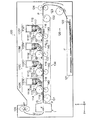
図1は、実施の形態に係る画像形成装置100の構成を概略的に示す図である。画像形成装置100は、例えば、電子写真カラープリンタである。画像形成装置100は、実施の形態に係る定着装置1を有する。
<< 1 >> Image forming apparatus FIG. 1 is a diagram schematically showing a configuration of an
図1に示されるように、画像形成装置100は、主要な構成として、電子写真方式により用紙などの媒体P上に現像剤像(トナー像)を形成する画像形成部110Y,110M,110C,110Kと、画像形成部110Y,110M,110C,110Kに媒体Pを供給する媒体供給部120と、媒体Pを搬送する搬送部130と、画像形成部110Y,110M,110C,110Kの各々に対応するように配置された転写部としての転写ローラ140と、媒体P上に転写された現像剤像Qを定着させる定着装置1と、定着装置1を通過した媒体Pを外部に排出する媒体排出部としての排紙ローラ対125とを有する。なお、画像形成装置100が有する画像形成部の数は、3以下又は5以上であってもよい。また、画像形成装置100は、電子写真プロセスによって媒体P上に画像を形成する装置であれば、画像形成部の数が1つであるモノクロプリンタであってもよい。
As shown in FIG. 1, the
図1に示されるように、媒体供給部120は、用紙カセット121と、用紙カセット121内に積載された媒体Pを1枚ずつ繰り出すホッピングローラ122と、用紙カセット121から繰り出された媒体Pを搬送するレジストローラ123と、媒体Pを搬送するローラ対124とを有する。
As shown in FIG. 1, the
画像形成部110Y,110M,110C,110Kは、媒体P上にイエロー(Y)の現像剤像、マゼンタ(M)の現像剤像、シアン(C)の現像剤像、及びブラック(K)の現像剤像をそれぞれ形成する。画像形成部110Y,110M,110C,110Kは、媒体搬送路に沿って搬送方向に(すなわち、図1において右から左に)並んで配置される。画像形成部110Y,110M,110C,110Kは、着脱自在に形成された各色用の画像形成ユニット112Y,112M,112C,112Kをそれぞれ有する。
The
画像形成部110Y,110M,110C,110Kは、各色用の露光装置としての光プリントヘッド111Y,111M,111C,111Kをそれぞれ有する。
The
画像形成ユニット112Y,112M,112C,112Kの各々は、回転可能に支持された像担持体としての感光体ドラム113と、感光体ドラム113の表面を一様に帯電させる帯電部材としての帯電ローラ114と、光プリントヘッド111Y,111M,111C,111Kによる露光によって感光体ドラム113の表面に静電潜像を形成した後に、感光体ドラム113の表面にトナーを供給して静電潜像に対応する現像剤像を形成する現像装置115とを有する。
Each of the
現像装置115は、トナーを収容する現像剤収容スペースを形成する現像剤収容部としてのトナー収容部と、感光体ドラム113の表面にトナーを供給する現像剤担持体としての現像ローラ116と、トナー収容部内に収容されたトナーを現像ローラ116に供給する供給ローラ117と、現像ローラ116の表面のトナー層の厚さを規制するトナー規制部材としての現像ブレード118とを有する。
The developing
光プリントヘッド111Y,111M,111C,111Kの各々による露光は、一様帯電した感光体ドラム113の表面に印刷用の画像データに基づいて実行される。光プリントヘッド111Y,111M,111C,111Kの各々は、感光体ドラム113の軸線方向に複数の発光素子が配列された発光素子アレイを含む。
The exposure by each of the
図1に示されるように、搬送部130は、媒体Pを静電吸着して搬送する搬送ベルト(転写ベルト)133と、駆動部により回転されて搬送ベルト133を駆動する駆動ローラ131と、駆動ローラ131と対を成して搬送ベルト133を張架するテンションローラ(従動ローラ)132とを有する。
As shown in FIG. 1, the
図1に示されるように、転写ローラ140は、搬送ベルト133を挟んで画像形成ユニット112Y,112M,112C,112Kの各々の感光体ドラム113に対向して配置されている。転写ローラ140によって、画像形成ユニット112Y,112M,112C,112Kの各々の感光体ドラム113の表面に形成された現像剤像(トナー像)は、媒体搬送路に沿って矢印方向に搬送される媒体Pの上面に順に転写されて、複数の現像剤像が重ねられたカラー画像が形成される。感光体ドラム113上に現像された画像(現像剤像)を媒体Pに転写した後に感光体ドラム113に残留したトナーを除去するクリーニング装置119を有する。
As shown in FIG. 1, the
定着装置1は、未定着の現像剤像Qを加熱及び加圧して媒体P上に定着させる。定着装置1の詳細は、後述する。
The
次に、画像形成装置100の動作を説明する。先ず、用紙カセット121内の媒体Pは、ホッピングローラ122によって繰り出され、レジストローラ123へ送られる。続いて、媒体Pはレジストローラ123からローラ対124を介して搬送ベルト133に送られ、この搬送ベルト133の走行に伴って、画像形成ユニット112Y,112M,112C,112Kへと搬送される。画像形成ユニット112Y,112M,112C,112Kにおいて、感光体ドラム113の表面は、帯電ローラ114によって帯電され、光プリントヘッド111Y,111M,111C,111Kによって露光され、静電潜像が形成される。静電潜像には、現像ローラ116上で薄層化されたトナーが静電的に付着されて各色の現像剤像が形成される。各色の現像剤像は、転写ローラ140によって媒体Pに転写され、媒体P上にカラーの現像剤像Qが形成される。転写後に、感光体ドラム113上に残留したトナーは、クリーニング装置119によって除去される。カラーの現像剤像Qが形成された媒体Pは、定着装置1に送られる。この定着装置1において、カラーの現像剤像Qが媒体Pに定着され、カラー画像が形成される。カラー画像が形成された媒体Pは、排紙ローラ対125によって用紙スタッカへ排出される。
Next, the operation of the
《2》定着装置
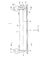
図2は、実施の形態に係る定着装置1の内部構造を概略的に示す斜視図である。図3は、定着装置1の内部を媒体の搬送方向F(+y軸方向)に見た正面図である。図4は、図3の定着装置1をIV−IV線で切る断面を概略的に示す断面図である。図5は、図4の定着装置1のA部を示す拡大断面図である。
<< 2 >> Fixing device FIG. 2 is a perspective view schematically showing an internal structure of the fixing
また、図6は、定着装置1のベルトユニット2の構造を概略的に示す分解斜視図である。図7は、図3の定着装置1をVII−VII線で切る断面を概略的に示す断面図である。図8は、図7のベルトユニット2のB部を示す拡大断面図である。図9は、ベルトユニット2の無端ベルトの内側の構造を概略的に示す分解斜視図である。
Further, FIG. 6 is an exploded perspective view schematically showing the structure of the
図2及び図3に示されるように、定着装置1は、加熱装置としてのベルトユニット2と、ベルトユニット2に接触する加圧部材としての加圧ローラ3と、ベルトユニット2及び加圧ローラ3を支持するサイドフレーム4及び5(「左サイドフレーム4」及び「右サイドフレーム5」とも言う)とを有する。サイドフレーム4及び5は、定着装置1の本体構造であるフレーム6の一部分である。未定着の現像剤像Q(図1に示される)を備えた媒体P(図1に示される)が搬送方向Fに搬送され、ベルトユニット2と加圧ローラ3との間の接触位置、すなわちニップ部Nを通過することで、媒体Pが加熱及び加圧されて、媒体P上に現像剤像Qが定着される。
As shown in FIGS. 2 and 3, the fixing
図2及び図3に示されるように、サイドフレーム4及び5には、互いに同軸的に配置された支軸41及び51が備えられている。図2及び図4に示されるように、サイドフレーム4には支軸41を中心にD4方向に回動可能に支持されたレバー部材42が備えられている。図6及び図7に示されるように、サイドフレーム5には支軸51を中心にD5方向に回動可能に支持されたレバー部材52が備えられている。
As shown in FIGS. 2 and 3, the side frames 4 and 5 are provided with
図4から図9に示されるように、ベルトユニット2は、ステー21と、ステー21に固定された保持部材22とを有している。ステー21と保持部材22とは、ベルトユニット2をサイドフレーム4及び5に支持するための支持部23を構成する。ただし、支持部23の構造は、図示の例に限定されず、種々の変更が可能である。図2から図4及び図6に示されるように、ステー21のx軸方向の両端部211及び212は、レバー部材42及び52にそれぞれ固定されている。固定方法は、限定されないが、例えば、ネジによる固定である。このため、ベルトユニット2は、レバー部材42及び52と共に支軸41及び51を中心に、図4のD4方向、すなわち図7のD5方向に回動可能に支持される。
As shown in FIGS. 4 to 9, the
また、図4から図9に示されるように、ベルトユニット2は、保熱部材としての保熱板24と、板状のヒータ25と、熱拡散部材としての熱拡散板26と、無端ベルト27とを有する。保熱板24は、ヒータ25で発生した熱を一時的に蓄える蓄熱性能と、ヒータ25で発生した熱を上部に(+z軸方向に)伝達させにくくするための熱遮断性能とを有する。ただし、ヒータ25が、保熱板24の性能を有する場合又はヒータ25の上部の温度上昇を許容する場合などには、保熱板24を備える必要はない。また、保熱板24及びヒータ25は、板状の形状又は平板状の形状に限定されない。
Further, as shown in FIGS. 4 to 9, the
図4から図9に示されるように、熱伝達特性を向上させるために、保熱板24の下面242とヒータ25の上面251とは、予め塗布されたグリース(第1のグリース)を介して密着している。このグリース(第1のグリース)は、例えば、熱伝導グリースである。また、熱伝達特性を向上させるために、ヒータ25の下面252と熱拡散板26の第1の面261とは、予め塗布されたグリース(第2のグリース)を介して密着している。このグリース(第2のグリース)は、例えば、熱伝導グリースである。第1のグリースと第2のグリースとは同じ成分のものであってもよく、異なる成分のものであってもよい。また、保熱板24とヒータ25との間は、グリースを塗布しない場合もある。また、無端ベルト27と熱拡散板26の摺動部との間には、摺動性を高め、摩耗を減らすために摺動グリースが塗布される。
As shown in FIGS. 4 to 9, in order to improve the heat transfer characteristics, the
図4及び図5に示されるように、保熱板24、ヒータ25、及び熱拡散板26は、無端ベルト27の内側に配置される。保熱板24、ヒータ25、及び熱拡散板26は、グリースの接着力によって一体的な構造物を形成する。保熱板24とヒータ25との間にグリースを塗布しない場合には、ヒータ25及び熱拡散板26は、グリースの接着力によって一体的な構造物を形成する。
As shown in FIGS. 4 and 5, the
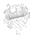
図4から図6及び図9に示されるように、熱拡散板26は、ヒータ25の下面252に接する第1の面261と、無端ベルト27の内面271に接する摺動面である第2の面262と、ヒータ25より搬送方向Fの上流側に備えられた第1の壁部263と、ヒータ25より搬送方向Fの下流側に備えられた第2の壁部264とを有する。第1の壁部263及び第2の壁部264は概ね+z軸方向に、すなわち、保持部材22に向けて立設している。第1の壁部263及び第2の壁部264は、熱拡散板26の長手方向すなわちx軸方向の全域に備えられている。保持部材22は、第1の壁部263が挿入される長溝である第1の溝部221と、第2の壁部264が挿入される長溝である第2の溝部222とを有する。第1の溝部221と第2の溝部222とは、保持部材22の長手方向すなわちx軸方向の全域に形成されている。図5及び図8に示されるように、熱拡散板26の断面形状は、略コの字状である。
As shown in FIGS. 4 to 6 and 9, the
熱拡散板26の幅方向すなわちx軸方向の両端は、幅方向における無端ベルト27の両端よりも外側に配置されることが望ましい。熱拡散板26の幅方向の両端には壁部が存在しないが、熱拡散板26の幅方向の両端からグリースが漏れ出たとしても、グリースが無端ベルト27の内面に付着しないからである。
It is desirable that both ends of the
熱拡散板26は、0.2mmから1.0mmの範囲内の厚さを持つ金属板であることが望ましい。熱拡散板26は、例えば、ステンレス、アルミニウム合金、又は鉄などの金属薄板に、無端ベルト27との摺動面の摩擦係数を低くし且つ耐摩耗性能を高くするための処理(例えば、ガラスコーティング又は硬質クロムコーティング)を行っている。この場合、第1の壁部263及び第2の壁部264として、金属板の折り曲げ加工によって形成される折り曲げ部を使用することができる。
The
図5、図6、図8及び図9に示されるように、第1の壁部263は、第1の溝部221内の突起部(フック部)221a(図8)及び221b(図5)に係合する(引っ掛かる又は嵌まる)係合部としての係合孔263a及び263bを有している。同様の突起部と係合孔を、第1の壁部263と第1の溝部221にではなく、又は、第1の壁部263と第1の溝部221に加えて、第2の壁部264と第2の溝部222内に備えてもよい。なお、第1の壁部263に係合孔が形成され、第1の壁部263に係合孔に係合する(引っ掛かる又は嵌まる)突起部を備えてもよい。
As shown in FIGS. 5, 6, 8 and 9, the
第1の溝部221は、第1の壁部263の先端が第1の溝部221の底面に接触しない深さを有し、第2の溝部222は、第2の壁部264の先端が第2の溝部222の底面に接触しない深さを有する。このような構造により、熱拡散板26は、第1の溝部221及び第2の溝部222の深さ方向(略z軸方向)に移動可能である。
The
図4から図6に示されるように、無端ベルト27は、ステー21の両端側のガイド面213及び214(図6)によって無端ベルト27の周方向(D2方向)に移動可能に支持される。図4及び図5に示されるように、無端ベルト27の内面271は熱拡散板26の第2の面262と摺動可能に接触する。
As shown in FIGS. 4 to 6, the
図2から図4に示されるように、無端ベルト27の外面272は、加圧ローラ3の周面と接触し、無端ベルト27と加圧ローラ3の接触位置(すなわち、接触範囲)にニップ部Nを形成する。加圧ローラ3は、モータ等の駆動力発生手段で発生した駆動力を伝達する駆動力伝達手段としての駆動ギヤ71〜73を介して受け取り、回転する。無端ベルト27は、加圧ローラ3のD3方向の回転に従動して、無端ベルト27の周方向であるD2方向に移動する。
As shown in FIGS. 2 to 4, the
図5に示されるように、現像剤像Qの定着動作時には、加圧ローラ3は無端ベルト27に押し付け力を付与している。この押し付け力は、例えば、図2に示される付勢手段としてのスプリング43及び53が、支軸41及び51を中心に回動するレバー部材42及び52を+y方向に押す力によって発生する。加圧ローラ3によって無端ベルト27の外面272に保持部材22に向かう押し付け力が付与されているときに、熱拡散板26、ヒータ25、及び保熱板24は、保持部材22に向けて押し付けられた密着状態である。つまり、密着状態は、無端ベルト27の内側に接する熱拡散板26、その上のヒータ25、その上の保熱板24は、保熱板24の上面241が保持部材22の下部の当接部としての当接面223に当接するまで押し上げられて、これらが互いに密着した状態である。
As shown in FIG. 5, the
無端ベルト27の外面272に加圧ローラ3による押し付け力が付与されていないときには、熱拡散部材26、ヒータ25、及び保熱板24は、保熱板24が保持部材22の当接面223から離れたフローティング状態である。
When the pressing force by the
印刷時にベルトユニット2が加圧ローラ3に押し付けられると(すなわち、加圧ローラ3がベルトユニット2からの押し付けに抗する力をベルトユニット2に付与すると)、ステー21で支えられた保持部材22の第1の溝221と第2の溝222によって第1の壁部263と第2の壁部264がガイドされて、熱拡散板26が略+z軸方向に押し上げられる。保持部材22の下部の当接面223と熱拡散板26の第1の面261との間に挟まれたヒータ25及び保熱板24は、熱拡散板26により押し付けられヒータ25と保熱板24の間が密着され、塗布されたグリースの一部(すなわち、グリースの内の過剰な部分)が熱拡散板26の第1の面261上に追い出される場合がある。また、熱拡散板26とヒータ25との間のグリースも同様な状態になる場合がある。熱拡散板26の第1の面261上に追い出されたグリースは、熱拡散板26の第1の面261において第1の壁部263と第2の壁部264の内側に滞留するため、無端ベルト27の内面271へ付着しない。
When the
以上に説明したように、実施の形態に係る定着装置1によれば、ヒータ25と熱拡散板26との間に塗布されたグリース又はヒータ25と保熱板24との間に塗布されたグリースが、熱拡散板26の第1の面261上に漏れ出ても、第1の壁部263と第2の壁部264とによってグリースが第1の面261の外側に流出することを阻止できる。このため、漏れ出たグリースが無端ベルト27の内面271と熱拡散板26の第2の面(下面)との間の摺動グリースに混入し、摺動性を悪化させたり、熱伝達率のムラを発生させたりする状況は発生しない。このため、漏れ出たグリースの流出に起因する、現像剤像の加熱不足、その結果生じる定着不良を防止することができる。
As described above, according to the
また、実施の形態に係る定着装置1によれば、保持部材22の当接面223と無端ベルト27の内面271との間で、熱拡散板26の第1の面261との間に、保熱板24、ヒータ25、及び熱拡散板26を上下方向(+z軸方向、−z軸方向)に移動可能なフローティング状態とする構造にして、加圧ローラ3の押し付け力で保熱板24が保持部材22に密着する密着状態になる。このため、各部品の寸法バラツキに関係なく、ヒータ25に熱拡散板26及び無端ベルト27を密着加圧することができる。よって、加熱量の不足による定着不良を防止できる。
Further, according to the
また、実施の形態に係る定着装置1によれば、熱拡散板26は、厚さが0.2mmから1.0mmの範囲内と薄く、また、材質として金属薄板をコの字に曲げた簡単な形状で安価に熱容量を少なくでき、ウォームアップ(WU)時間を短縮することができる。
Further, according to the
《3》変形例
上記実施の形態では、ヒータ25の上面251と保持部材22の当接面223との間に保熱板24を備えた構造を説明した。しかし、定着装置1は、保熱板24を備えない構造を採用してもよい。この場合には、ヒータ25の上面251が保持部材22の当接面223に当接する。
<< 3 >> Deformation Example In the above embodiment, a structure in which a
また、上記実施の形態では、画像形成装置100がカラープリンタである場合を説明した。しかし、画像形成装置100は、電子写真プロセスを利用する他の装置であってもよい。画像形成装置100は、例えば、多機能周辺装置(MFP)、ファクシミリ、複写機であってもよい。
Further, in the above embodiment, the case where the
1 定着装置、 2 ベルトユニット(加熱装置)、 3 加圧ローラ(加圧部材)、 4,5 サイドフレーム、 6 フレーム、 21 ステー、 22 保持部材、 23 支持部、 24 保熱板(保熱部材)、 25 ヒータ、 26 熱拡散板(熱拡散部材)、 27 無端ベルト、 41,51 支軸、 42,52 レバー部材、 221 第1の溝部、 222 第2の溝部、 223 当接面(当接部)、 261 第1の面、 262 第2の面、 263 第1の壁部、 264 第2の壁部、 271 内面、 272 外面、 F 搬送方向、 N 接触位置(ニップ部)、 P 媒体、 Q 現像剤像。 1 Fixing device, 2 Belt unit (heating device), 3 Pressurizing roller (pressurizing member), 4, 5 Side frame, 6 frame, 21 stay, 22 Holding member, 23 Support part, 24 Heat insulating plate (heat insulating member) ), 25 heater, 26 heat diffusion plate (heat diffusion member), 27 endless belt, 41,51 support shaft, 42,52 lever member, 221 first groove, 222 second groove, 223 contact surface (contact) Part), 261 first surface, 262 second surface, 263 first wall part, 264 second wall part, 271 inner surface, 272 outer surface, F transport direction, N contact position (nip part), P medium, Q Developer image.
Claims (13)
前記ベルトユニットに接触する加圧部材と、
を有し、
媒体が前記ベルトユニットと前記加圧部材との間の接触位置を通過することで、前記媒体上に現像剤像を定着させる定着装置であって、
前記ベルトユニットは、
支持部と、
前記支持部に移動可能に支持され、前記加圧部材に接触する外面を有する無端ベルトと、
前記無端ベルトの内側に配置されたヒータと、
前記ヒータで発生する熱を前記無端ベルトに伝える熱拡散部材と、
を有し、
前記熱拡散部材は、
前記ヒータに接する第1の面と、
前記無端ベルトの内面に接する第2の面と、
前記ヒータより前記媒体の搬送方向の上流側に備えられた第1の壁部と、
前記ヒータより前記搬送方向の下流側に備えられた第2の壁部と、
を有し、
前記支持部は、
前記第1の壁部が挿入される第1の溝部と、
前記第2の壁部が挿入される第2の溝部と、
を有し、
前記ヒータと前記熱拡散部材の前記第1の面との間に第1のグリースが塗布されており、
前記熱拡散部材の前記搬送方向に直交する幅方向の前記第1の壁部及び前記第2の壁部を含む両端は、前記幅方向における前記無端ベルトの両端よりも外側に配置されており、
前記加圧部材によって前記無端ベルトの前記外面に前記支持部に向かう押し付け力が付与されているときに、前記熱拡散部材及び前記ヒータは、前記支持部の当接面と対向して配設される
ことを特徴とする定着装置。 With the belt unit
A pressure member that comes into contact with the belt unit and
Have,
A fixing device for fixing a developer image on the medium by passing the medium through a contact position between the belt unit and the pressure member.
The belt unit is
Support part and
An endless belt that is movably supported by the support portion and has an outer surface that contacts the pressurizing member.
The heater arranged inside the endless belt and
A heat diffusion member that transfers the heat generated by the heater to the endless belt,
Have,
The heat diffusion member is
The first surface in contact with the heater and
A second surface in contact with the inner surface of the endless belt and
A first wall portion provided on the upstream side of the heater in the transport direction of the medium, and
A second wall portion provided on the downstream side in the transport direction from the heater, and
Have,
The support portion
The first groove into which the first wall is inserted, and
A second groove into which the second wall is inserted, and
Have,
A first grease is applied between the heater and the first surface of the heat diffusion member.
Both ends of the heat diffusion member including the first wall portion and the second wall portion in the width direction orthogonal to the transport direction are arranged outside the ends of the endless belt in the width direction.
When the pressure member applies a pressing force toward the support portion to the outer surface of the endless belt, the heat diffusion member and the heater are arranged so as to face the contact surface of the support portion. A fixing device characterized by being a belt.
前記無端ベルトの前記外面に前記押し付け力が付与されているときに、前記熱拡散部材、前記ヒータ、及び前記保熱部材は、前記支持部の当接面と対向して配設される
ことを特徴とする請求項1に記載の定着装置。 Further having a heat retaining member arranged between the heater and the support portion and temporarily accumulating the heat generated by the heater.
When the pressing force is applied to the outer surface of the endless belt, the heat diffusion member, the heater, and the heat retention member are arranged so as to face the contact surface of the support portion. The fixing device according to claim 1, wherein the fixing device is characterized.
前記保熱部材と前記ヒータとの間に第2のグリースが塗布されている
ことを特徴とする請求項4又は5に記載の定着装置。 A first grease is applied between the heater and the heat diffusion member.
The fixing device according to claim 4 or 5 , wherein a second grease is applied between the heat retaining member and the heater.
前記加圧ローラの回転に従動して前記無端ベルトが周方向に移動する
ことを特徴とする請求項1から9のいずれか1項に記載の定着装置。 The pressurizing member is a pressurizing roller.
The fixing device according to any one of claims 1 to 9, wherein the endless belt moves in the circumferential direction in accordance with the rotation of the pressure roller.
前記第2の溝部は、前記第2の壁部の先端が前記第2の溝部の底面に接触しない深さを有する
ことを特徴とする請求項1から10のいずれか1項に記載の定着装置。 The first groove portion has a depth at which the tip of the first wall portion does not come into contact with the bottom surface of the first groove portion.
The fixing device according to any one of claims 1 to 10, wherein the second groove portion has a depth at which the tip end of the second wall portion does not come into contact with the bottom surface of the second groove portion. ..
前記第1の壁部及び前記第2の壁部は、前記金属板の折り曲げ部である
ことを特徴とする請求項1から11のいずれか1項に記載の定着装置。 The heat diffusion member is a metal plate having a thickness in the range of 0.2 mm to 1.0 mm.
The fixing device according to any one of claims 1 to 11 , wherein the first wall portion and the second wall portion are bent portions of the metal plate.
Priority Applications (2)
| Application Number | Priority Date | Filing Date | Title |
|---|---|---|---|
| JP2018011079A JP6954153B2 (en) | 2018-01-26 | 2018-01-26 | Fixing device and image forming device |
| US16/249,878 US10459383B2 (en) | 2018-01-26 | 2019-01-16 | Fixing device and image forming apparatus |
Applications Claiming Priority (1)
| Application Number | Priority Date | Filing Date | Title |
|---|---|---|---|
| JP2018011079A JP6954153B2 (en) | 2018-01-26 | 2018-01-26 | Fixing device and image forming device |
Publications (3)
| Publication Number | Publication Date |
|---|---|
| JP2019128507A JP2019128507A (en) | 2019-08-01 |
| JP2019128507A5 JP2019128507A5 (en) | 2020-07-02 |
| JP6954153B2 true JP6954153B2 (en) | 2021-10-27 |
Family
ID=67392836
Family Applications (1)
| Application Number | Title | Priority Date | Filing Date |
|---|---|---|---|
| JP2018011079A Active JP6954153B2 (en) | 2018-01-26 | 2018-01-26 | Fixing device and image forming device |
Country Status (2)
| Country | Link |
|---|---|
| US (1) | US10459383B2 (en) |
| JP (1) | JP6954153B2 (en) |
Families Citing this family (9)
| Publication number | Priority date | Publication date | Assignee | Title |
|---|---|---|---|---|
| JP2020003611A (en) * | 2018-06-27 | 2020-01-09 | 株式会社沖データ | Fixation device and image formation device |
| JP2021018284A (en) * | 2019-07-18 | 2021-02-15 | キヤノン株式会社 | Fixing device and image forming apparatus |
| JP7363312B2 (en) * | 2019-09-30 | 2023-10-18 | 富士フイルムビジネスイノベーション株式会社 | Fixing device and image forming device |
| JP2021063940A (en) * | 2019-10-16 | 2021-04-22 | 富士ゼロックス株式会社 | Fixing device and image forming apparatus |
| JP2021086022A (en) | 2019-11-28 | 2021-06-03 | 株式会社沖データ | Fixing device and image forming apparatus |
| JP7354857B2 (en) | 2020-01-30 | 2023-10-03 | 沖電気工業株式会社 | Fixing device and image forming device |
| JP2021131482A (en) | 2020-02-20 | 2021-09-09 | 株式会社沖データ | Fixing device and image forming apparatus |
| US10935912B1 (en) | 2020-03-12 | 2021-03-02 | Toshiba Tec Kabushiki Kaisha | Heating device having first and second heat transfer units for an image forming unit |
| JP2022046302A (en) | 2020-09-10 | 2022-03-23 | 沖電気工業株式会社 | Fixing device and image forming apparatus |
Family Cites Families (8)
| Publication number | Priority date | Publication date | Assignee | Title |
|---|---|---|---|---|
| JP4732088B2 (en) * | 2005-09-13 | 2011-07-27 | キヤノン株式会社 | Image heating device |
| JPH11260533A (en) * | 1998-03-06 | 1999-09-24 | Canon Inc | Heating body assembly, heating apparatus, and image forming apparatus |
| WO2005054960A1 (en) * | 2003-12-02 | 2005-06-16 | Canon Denshi Kabushiki Kaisha | Metallic belt, fixing belt, and thermal fixing device |
| JP2010032697A (en) | 2008-07-28 | 2010-02-12 | Canon Inc | Image fixing device |
| US9229379B2 (en) * | 2012-09-11 | 2016-01-05 | Ricoh Company, Limited | Fixing device and image forming apparatus |
| KR20140085118A (en) * | 2012-12-27 | 2014-07-07 | 삼성전자주식회사 | Fixing device and image forming apparatus using the same |
| JP2016114876A (en) * | 2014-12-17 | 2016-06-23 | 株式会社リコー | Fixing device and image forming apparatus |
| JP6497147B2 (en) * | 2015-03-17 | 2019-04-10 | 株式会社リコー | Fixing apparatus and image forming apparatus |
-
2018
- 2018-01-26 JP JP2018011079A patent/JP6954153B2/en active Active
-
2019
- 2019-01-16 US US16/249,878 patent/US10459383B2/en active Active
Also Published As
| Publication number | Publication date |
|---|---|
| JP2019128507A (en) | 2019-08-01 |
| US10459383B2 (en) | 2019-10-29 |
| US20190235425A1 (en) | 2019-08-01 |
Similar Documents
| Publication | Publication Date | Title |
|---|---|---|
| JP6954153B2 (en) | Fixing device and image forming device | |
| US8224220B2 (en) | Fixing device and image forming apparatus capable of adjusting amount of oil applied for fixing | |
| US7764913B2 (en) | Fixing device and image forming apparatus | |
| JP6776647B2 (en) | Fixing device and image forming device | |
| KR101498105B1 (en) | Heating device, image forming apparatus, heating member and mounting method | |
| JP2008058563A (en) | Pressing member, fixing device using same, and image forming apparatus | |
| JP2009069701A (en) | Fixing device and image forming apparatus | |
| JP2009036812A (en) | Fixing device and image forming apparatus | |
| US7986908B2 (en) | Fixing device and image forming apparatus | |
| US9195182B2 (en) | Image heating apparatus, lubricant application system, lubricant application method, and lubricant container-applicator | |
| JP2007057784A (en) | Image forming apparatus | |
| JP2020046569A (en) | Fixing device and image forming device | |
| JP2014191039A (en) | Fixing device and image forming apparatus | |
| JP5034831B2 (en) | Fixing apparatus and image forming apparatus | |
| JP6190761B2 (en) | Image forming apparatus | |
| JP5347320B2 (en) | Fixing apparatus and image forming apparatus | |
| JP2008241843A (en) | Fixing device and image forming apparatus | |
| JP6122797B2 (en) | Fixing apparatus and image forming apparatus | |
| JP2015161841A (en) | Fixing device and image forming apparatus | |
| JP7047622B2 (en) | Fixing device and image forming device | |
| US11131948B2 (en) | Liquid applying device for fixing belt | |
| JP5739830B2 (en) | Fixing apparatus and image forming apparatus | |
| JP5990794B2 (en) | Fixing apparatus and image forming apparatus | |
| JP2019101372A (en) | Fixation device and image forming apparatus | |
| EP2950158B1 (en) | Fixing device and image forming apparatus |
Legal Events
| Date | Code | Title | Description |
|---|---|---|---|
| A521 | Written amendment |
Free format text: JAPANESE INTERMEDIATE CODE: A523 Effective date: 20200512 |
|
| A621 | Written request for application examination |
Free format text: JAPANESE INTERMEDIATE CODE: A621 Effective date: 20200512 |
|
| A977 | Report on retrieval |
Free format text: JAPANESE INTERMEDIATE CODE: A971007 Effective date: 20210317 |
|
| A131 | Notification of reasons for refusal |
Free format text: JAPANESE INTERMEDIATE CODE: A131 Effective date: 20210406 |
|
| A521 | Written amendment |
Free format text: JAPANESE INTERMEDIATE CODE: A523 Effective date: 20210603 |
|
| A711 | Notification of change in applicant |
Free format text: JAPANESE INTERMEDIATE CODE: A712 Effective date: 20210615 |
|
| A521 | Written amendment |
Free format text: JAPANESE INTERMEDIATE CODE: A523 Effective date: 20210616 |
|
| TRDD | Decision of grant or rejection written | ||
| A01 | Written decision to grant a patent or to grant a registration (utility model) |
Free format text: JAPANESE INTERMEDIATE CODE: A01 Effective date: 20210831 |
|
| A61 | First payment of annual fees (during grant procedure) |
Free format text: JAPANESE INTERMEDIATE CODE: A61 Effective date: 20210913 |
|
| R150 | Certificate of patent or registration of utility model |
Ref document number: 6954153 Country of ref document: JP Free format text: JAPANESE INTERMEDIATE CODE: R150 |