US7764913B2 - Fixing device and image forming apparatus - Google Patents
Fixing device and image forming apparatus Download PDFInfo
- Publication number
- US7764913B2 US7764913B2 US11/723,007 US72300707A US7764913B2 US 7764913 B2 US7764913 B2 US 7764913B2 US 72300707 A US72300707 A US 72300707A US 7764913 B2 US7764913 B2 US 7764913B2
- Authority
- US
- United States
- Prior art keywords
- pressing
- supporting
- fixing device
- urging
- roller
- Prior art date
- Legal status (The legal status is an assumption and is not a legal conclusion. Google has not performed a legal analysis and makes no representation as to the accuracy of the status listed.)
- Active, expires
Links
Images


Classifications
-
- G—PHYSICS
- G03—PHOTOGRAPHY; CINEMATOGRAPHY; ANALOGOUS TECHNIQUES USING WAVES OTHER THAN OPTICAL WAVES; ELECTROGRAPHY; HOLOGRAPHY
- G03G—ELECTROGRAPHY; ELECTROPHOTOGRAPHY; MAGNETOGRAPHY
- G03G15/00—Apparatus for electrographic processes using a charge pattern
- G03G15/20—Apparatus for electrographic processes using a charge pattern for fixing, e.g. by using heat
- G03G15/2003—Apparatus for electrographic processes using a charge pattern for fixing, e.g. by using heat using heat
- G03G15/2014—Apparatus for electrographic processes using a charge pattern for fixing, e.g. by using heat using heat using contact heat
- G03G15/206—Structural details or chemical composition of the pressure elements and layers thereof
-
- G—PHYSICS
- G03—PHOTOGRAPHY; CINEMATOGRAPHY; ANALOGOUS TECHNIQUES USING WAVES OTHER THAN OPTICAL WAVES; ELECTROGRAPHY; HOLOGRAPHY
- G03G—ELECTROGRAPHY; ELECTROPHOTOGRAPHY; MAGNETOGRAPHY
- G03G2215/00—Apparatus for electrophotographic processes
- G03G2215/20—Details of the fixing device or porcess
- G03G2215/2003—Structural features of the fixing device
- G03G2215/2009—Pressure belt
Definitions
- the present invention relates to a fixing device and an image forming apparatus.
- a charge roller charges a surface of a photosensitive drum.
- An exposure device such as an LED head exposes the surface of the photosensitive drum to form a static latent image or a latent image thereon.
- a developing roller attaches a thin layer of toner to the static latent image to form a toner image.
- a transfer roller transfers the toner image to a sheet.
- a fixing unit or fixing device fixes the toner image to the sheet before discharging the sheet.
- Patent Reference has disclosed a conventional fixing device of a belt nip type.
- the conventional fixing device is provided with a pressing pad pressed against a fixing roller or a fixing member through a pressing belt.
- FIG. 2 is a schematic sectional view showing the conventional fixing device.
- a fixing device 101 includes a pressing belt assembly 102 ; a fixing roller 103 facing the pressing belt assembly 102 ; a pressing belt 105 ; a pressing pad 106 ; a spring 107 for urging the pressing pad 106 against the fixing roller 103 through the pressing belt 105 ; a holder 108 for holding the pressing pad 106 ; and a heater 111 .
- the holder 108 is guided with a guide member (not shown) to freely slide back and forth.
- a nip portion n is formed between the pressing belt assembly 102 and the fixing roller 103 .
- the pressing belt 105 when the pressing belt 105 moves, an inner circumferential surface of the pressing belt 105 slides against an upper surface of the pressing pad 106 , thereby causing frictional resistance. Accordingly, the pressing pad 106 may be inclined, vibrate, or wobble, so that the holder 108 may seize the guide member. As a result, it is difficult to stably press the pressing pad 106 against the fixing roller 103 , thereby causing distortion, shift, or irregularity in an image, and lowering image quality.
- an object of the present invention is to provide a fixing device and an image forming apparatus capable of solving the problems of the conventional fixing device.
- the fixing device it is possible to stably press a pressing pad against a fixing member, thereby improving image quality.
- a fixing device comprises a heating member for heating a recording medium having a developer image; a pressing member for pressing the recording medium against the heating member; a supporting member for supporting the pressing member; a supporting shaft for supporting the supporting member to be freely rotatable; and an urging member for urging the supporting member in a specific rotational direction and urging the pressing member against the heating member.
- the fixing device comprises the heating member for heating the recording medium having the developer image; the pressing member for pressing the recording medium against the heating member; the supporting member for supporting the pressing member; the supporting shaft for supporting the supporting member to be freely rotatable; and the urging member for urging the supporting member in the specific rotational direction and urging the pressing member against the heating member.
- the supporting shaft supports the supporting member to be freely rotatable, and the supporting member supports the pressing member.
- the urging member urges the supporting member in the specific rotational direction, and urges the pressing member against the heating member. Accordingly, the pressing member is not inclined, or does not vibrate or wobble, so that the pressing member does not seize other component. As a result, it is possible to stably press the pressing member against the heating member, thereby preventing distortion, shift, or irregularity in an image, and improving image quality.
- FIG. 1 is a schematic sectional view showing a fixing device according to a first embodiment of the present invention
- FIG. 2 is a schematic sectional view showing a conventional fixing device
- FIG. 3 is a schematic sectional view showing a printer according to the first embodiment of the present invention.
- FIG. 4 is a perspective view showing a primary portion of the fixing device according to the first embodiment of the present invention.
- FIG. 5 is an exploded perspective view showing the primary portion of the fixing device according to the first embodiment of the present invention.
- FIG. 6 is a graph showing a pressure distribution of a nip portion of the fixing device according to the first embodiment of the present invention.
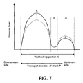
- FIG. 7 is a graph No. 1 showing a pressure distribution of a nip portion of a conventional fixing device
- FIG. 8 is a graph No. 2 showing a pressure distribution of the nip portion of the conventional fixing device
- FIG. 9 is a graph No. 3 showing a pressure distribution of the nip portion of the conventional fixing device
- FIG. 10 is a schematic sectional view showing a fixing device according to a second embodiment of the present invention.
- FIG. 11 is a perspective view showing a primary portion of the fixing device according to the second embodiment of the present invention.
- FIG. 12 is an exploded perspective view showing the primary portion of the fixing device according to the second embodiment of the present invention.
- a printer is used as an image forming apparatus for forming an image.
- FIG. 3 is a schematic sectional view showing a printer according to the first embodiment of the present invention.
- the printer includes a sheet supply cassette 11 as a recording medium storage unit disposed at a lower portion of the printer for storing a sheet (not shown) as a recording medium.
- a sheet supply mechanism is disposed adjacent to a front end of the sheet supply cassette 11 for separating and transporting the sheet one by one.
- the sheet supply mechanism includes sheet supply rollers 12 a and 12 b and a separation roller 13 .
- the sheet supply mechanism transports the sheet to a transport roller 14 disposed above the sheet supply mechanism, and then transports the sheet further to a transport roller 15 .
- a transport belt 17 as a transport member or a first transfer member moves and transports the sheet, so that the sheet passes through between image forming units 16 Bk, 16 Y, 16 M, and 16 C as image forming devices for forming images in black, yellow, magenta, and cyan, and transfer rollers 51 Bk, 51 Y, 51 M, and 51 C as second transfer members.
- photosensitive drums 52 Bk, 52 Y, 52 M, and 52 C as image supporting members form toner images or developer images in each color.
- the transfer rollers 51 Bk, 51 Y, 51 M, and 51 C transfer the toner images to the sheet, thereby forming a toner image in colors.
- a transfer unit is formed of the transport belt 17 and the transfer rollers 51 Bk, 51 Y, 51 M, and 51 C.
- the sheet after transferring the toner image, the sheet is transported to a fixing device 18 of a belt nip type as a fixing unit.
- the fixing device 18 fixes the toner image in colors to the sheet, thereby forming an image in colors.
- a discharge transport roller 20 discharges the sheet outside the printer.
- LED heads 21 Bk, 21 Y, 21 M, and 21 C as exposure devices are arranged to face the image forming units 16 Bk, 16 Y, 16 M, and 16 C for exposing surfaces of the photosensitive drums 52 Bk, 52 Y, 52 M, and 52 C to form latent images.
- the image forming units 16 Bk, 16 Y, 16 M, and 16 C are detachably attached to a main body of the printer.
- An upper cover 23 is disposed at an upper portion of the printer to freely open and close.
- the LED heads 21 Bk, 21 Y, 21 M, and 21 C are supported on the upper cover 23 .
- the sheet includes an ordinary copy paper, and may include a special sheet such as an OHP sheet, a card, a postcard, a cardboard with an area weight of more than 100 g/m 2 , an envelope, and a coated sheet with large heat capacity.
- a special sheet such as an OHP sheet, a card, a postcard, a cardboard with an area weight of more than 100 g/m 2 , an envelope, and a coated sheet with large heat capacity.
- the sheet supply rollers 12 a and 12 b and the separation roller 13 separate and transport the sheet stored in the sheet supply cassette 11 one by one.
- the transport rollers 14 and 15 transport the sheet to the transport belt 17 .
- the photosensitive drums 52 Bk, 52 Y, 52 M, and 52 C are charged with a charge roller, and the LED heads 21 Bk, 21 Y, 21 M, and 21 C expose the surfaces of the photosensitive drums 52 Bk, 52 Y, 52 M, and 52 C to form the latent images.
- a developing roller develops the latent images to form the toner images or the developer images on the photosensitive drums 52 Bk, 52 Y, 52 M, and 52 C.
- the sheet passes through between the photosensitive drums 52 Bk, 52 Y, 52 M, and 52 C and the transfer rollers 51 Bk, 51 Y, 51 M, and 51 C for sequentially transferring the toner images in black, yellow, magenta, and cyan to the sheet, thereby forming the toner image in colors.
- the sheet After transferring the toner images, the sheet is transported to the fixing device 18 for fixing the toner image in colors to the sheet, thereby forming the image in colors.
- a cleaning blade as a cleaning device scrapes and removes toner remaining on the photosensitive drums 52 Bk, 52 Y, 52 M, and 52 C after transferring the toner images, so that toner can be used in a next charging operation.
- FIG. 1 is a schematic sectional view showing the fixing device 18 according to the first embodiment of the present invention.
- FIG. 4 is a perspective view showing a primary portion of the fixing device 18 according to the first embodiment of the present invention.
- FIG. 5 is an exploded perspective view showing the primary portion of the fixing device 18 according to the first embodiment of the present invention.
- FIG. 6 is a graph showing a pressure distribution of a nip portion of the fixing device 18 according to the first embodiment of the present invention.
- FIG. 7 is a graph No. 1 showing a pressure distribution of a nip portion of a conventional fixing device.
- FIG. 8 is a graph No. 2 showing a pressure distribution of the nip portion of the conventional fixing device.
- FIG. 9 is a graph No. 3 showing a pressure distribution of the nip portion of the conventional fixing device.
- a horizontal axis represents a width of the nip portion and a vertical axis represents a pressure level.
- a fixing roller 32 as a fixing member is pressed against a pressing belt assembly 33 as a pressing unit.
- a nip portion N is formed between the fixing roller 32 and the pressing belt assembly 33 for fixing a toner image T that is not fixed to a sheet P yet.
- the fixing roller 32 is supported on a bearing (not shown) to be freely rotatable, and is driven with a fixing motor (not shown) as a drive device to rotate clockwise at a specific circumferential speed.
- a thermistor (not shown) is disposed as a temperature detection unit adjacent to a surface of the fixing roller 32 .
- a heater 37 is disposed in the fixing roller 32 as a heating member or a heating source.
- the heater 37 is formed of a halogen lamp, and may include an induction heating member instead of the halogen lamp.
- the pressing belt assembly 33 includes a pressing roller 34 as a pushing member, a pressing belt 35 with an endless shape as a belt member, and a pressing pad 36 as a pressing member.
- a pair of springs 38 is provided as a first urging member for urging the pressing roller 34 toward the fixing roller 32 , so that the pressing roller 34 is pressed against the fixing roller 32 through the pressing belt 35 with a specific pressure or a pressing force. Accordingly, the sheet P is pressed against the fixing roller 32 . Further, the pressing belt 35 is placed in a contact state with the fixing roller 32 .
- the springs 38 are formed of a coil spring.
- the pressing pad 36 is disposed inside the pressing belt 35 at an upstream side of the pressing roller 34 in a direction that the pressing belt 35 moves.
- a plurality of springs 42 is provided as a second urging member for urging the pressing pad 36 toward the fixing roller 32 , so that the pressing pad 36 is pressed against the fixing roller 32 through the pressing belt 35 with a specific pressing force. Accordingly, the sheet P is pressed against the fixing roller 32 .
- the springs 42 are formed of a coil spring.
- the nip portion N is a contact area of the pressing belt 35 and the fixing roller 32 between the pressing roller 34 and the pressing pad 36 .
- the fixing roller 32 rotates, the pressing belt 35 moves with friction generated between the pressing belt 35 and the fixing roller 32 at the nip portion N. It is possible to easily change a width of the nip portion N (width in a direction that the pressing belt 35 moves) through changing a width of the pressing pad 36 .
- the fixing roller 32 is formed of a hollow roller having an outer diameter of about 28 mm.
- a core metal portion is covered with an elastic layer 32 a made of a porous silicone rubber with high temperature resistance and having a thickness of about 1.2 mm.
- an outer circumferential surface is coated with a fluorine resin layer 32 b as a release layer having a thickness of 30 ⁇ m.
- the core metal portion is formed of metal such as iron and steel, and may be formed of other metal such as aluminum.
- the pressing belt 35 has a two-layer structure formed of a base layer and a release layer coated on the base layer.
- the base layer is formed of a polyimide with high temperature resistance, and is formed in a belt member having a diameter of 30 mm and a thickness of 80 ⁇ m.
- the release layer is formed of a PFA coating having a thickness of 20 ⁇ m.
- the pressing roller 34 is formed of a material having hardness higher than at least that of the fixing roller 32 . Accordingly, the fixing roller 32 elastically deforms at a pressing portion of the pressing roller 34 relative to the fixing roller 32 , thereby maintaining a self-stripping function of the sheet P.
- the pressing roller 34 is formed of an elastic member having an outer diameter of 34 mm. More specifically, a metal core shaft 34 a is covered with an elastic member 34 b formed of a silicone sponge with heat resistance and having a thickness of 1 mm.
- the silicone sponge has a crown shape having an outer diameter difference of 0.1 mm to obtain a uniform pressure distribution along an axial direction of the pressing roller 34 .
- the pressing roller 34 and the fixing roller 32 form a nip portion C having a nip width of about 4 mm.
- the pressing pad 36 is formed of a base member; a heat resistant resin layer partially formed on the base member at a specific location; and a low friction member formed on a surface contacting with the pressing belt 35 . Further, the pressing pad 36 is disposed such that the low friction member contacts with an inner surface of the pressing pad 36 .
- the base member is formed of a metal member formed through an extruding process or a drawing process, i.e., an aluminum extruded member in the embodiment.
- the heat resistant resin layer is formed of a silicone rubber having a hardness of 15 to 40° (JIS A). In the embodiment, the heat resistant resin layer has a hardness of 40° and a thickness of about 1.0 mm. The heat resistant resin layer contacts with the pressing belt 35 in a contact width of about 4.0 mm.
- the pressing pad 36 has a crown shape having a center portion protruding by 0.1 mm relative to both end portions thereof to obtain a uniform pressure distribution along a longitudinal direction of the pressing pad 36 .
- the low friction member is provided for reducing friction between the inner surface of the pressing belt 35 and a surface of the pressing pad 36 .
- the low friction member is formed of a silicone type coating containing graphite, and has a thickness of 20 ⁇ m.
- the pressing pad 36 is disposed apart from the pressing roller 34 by about 1.0 mm.
- a plurality of springs 42 is disposed along the axial direction of the fixing roller 32 for urging the pressing pad 36 against the fixing roller 32 through the pressing belt 35 . Further, the pressing pad 36 and the fixing roller 32 form a nip portion A having a nip width of about 4.0 mm with the pressing belt 35 inbetween.
- FIG. 6 is a graph showing a pressure distribution of the nip portion of the fixing device 18 according to the first embodiment of the present invention.
- the pressing pad 36 is pressed against the fixing roller 32 in the nip portion A with an average surface pressure smaller than an average surface pressure of the pressing roller 34 pressed against the fixing roller 32 in the nip portion C.
- the average surface pressure is calculated from a total pressure applied in the nip portion A or C divided by an area of the nip portion A or C.
- the springs 38 urge the pressing roller 34 and the springs 42 urge the pressing pad 36 such that the average surface pressure in the nip portion C becomes about 2.0 kg/cm 2 and the average surface pressure in the nip portion A becomes about 0.8 kg/cm 2 .
- the pressing belt 35 and the fixing roller 32 form a nip portion B (small pressure portion), and the pressing belt 35 is pressed against the fixing roller 32 in the nip portion B with tension thereof.
- both end portions of the pressing roller 34 are supported on pressing roller levers 41 a disposed at left and right sides as a first supporting member through bearings br 1 , so that the pressing roller 34 is freely rotatable.
- the pressing roller levers 41 a are disposed to be freely rotatable around supporting shafts sh 1 ( FIG. 1 ) disposed on both side surfaces.
- the springs 38 are disposed between the pressing roller levers 41 a and a front plate 91 ( FIG. 1 ). Accordingly, the springs 38 urge the pressing roller levers 41 a in a counterclockwise direction ( FIG. 1 ), so that the pressing roller 34 is urged toward the fixing roller 32 .
- both end portions of the pressing pad 36 are fixed and supported to pressing pad levers 41 b disposed at left and right sides as a second supporting member.
- the pressing pad levers 41 b are disposed to be freely rotatable around the supporting shafts sh 1 ( FIG. 1 ) disposed on both side surfaces.
- the springs 42 are disposed between the pressing pad levers 41 b and a frame member 45 fixed to the pressing pad levers 41 b ( FIG. 1 ), so that the springs 42 urge the pressing pad 36 toward the fixing roller 32 .
- the springs 42 are disposed along the longitudinal direction of the pressing pad 36 to make the pressure distribution uniform at the nip portion A in the longitudinal direction.
- a guide member 44 is disposed around the frame member 45 for guiding the pressing belt 35 . Accordingly, the pressing belt 35 does not receive tension along a circumferential direction thereof except the nit portion N and surrounding areas thereof.
- the pressing belt 35 moves, the pressing belt 35 tries to move in the axial direction of the pressing roller 34 , that is, the longitudinal direction of the pressing pad 36 .
- an end portion of the pressing belt 35 contacts with an inner side surface of one of flange members f 1 formed between the guide member 44 and the pressing pad levers 41 b , thereby restricting the lateral movement of the pressing belt 35 .
- the supporting shafts sh 1 are disposed such that a rotational radius R 1 of the pressing roller 34 with the pressing roller levers 41 a becomes smaller than or equal to a rotational radius R 2 of the pressing pad 36 with the pressing pad levers 41 b (R 1 ⁇ R 2 ).
- the pressing roller levers 41 a and the pressing pad levers 41 b are disposed to be rotatable around the common supporting shafts sh 1 , thereby reducing the number of parts and a size of the fixing device 18 .
- the pressing roller levers 41 a and the pressing pad levers 41 b may be disposed to be rotatable around different supporting shafts.
- the fixing roller 32 starts rotating. That is, a gear disposed on one end of the fixing roller 32 engages a drive gear fixed to an output shaft of the fixing motor inside the main body of the printer, so that the fixing roller 32 rotates in a direction for transporting the sheet P.
- the fixing roller 32 rotates, the pressing belt 35 moves through friction with the fixing roller 32 at the nip portion N.
- a current is supplied to the heater 37 from a power supply circuit (not shown), so that the heater 37 heats the fixing roller 32 from inside thereof.
- the thermistor (not shown) detects a surface temperature of the fixing roller 32 thus heated, and inputs a result to a temperature control circuit of a control unit (not shown).
- the temperature control circuit controls the power supply circuit to supply the current to the heater 37 according to the surface temperature of the fixing roller 32 , thereby maintaining the surface temperature of the fixing roller 32 at a fixing temperature.
- the sheet P is transported to the nip portion N through the guide member 92 .
- the toner image T ( FIG. 1 ) is heated and fixed to the sheet P as a fixed image.
- a pressing pad 106 is disposed to be freely rotatable relative to a guide member. Accordingly, the pressing pad 106 may be inclined, vibrate, or wobble, so that the pressing pad 106 may seize the guide member.
- the pressing pad 106 seizes other component and the pressing pad 106 does not move back to an original pressing position, the pressing pad 106 is urged toward a fixing roller 103 with a smaller force. Since springs urge the pressing pad 106 , a reactive force is applied to a frame member to move downward and is applied to pressing roller levers to rotate in a clockwise direction. Accordingly, as shown in FIG. 7 , when a pressure level at a nip portion A decreases, a pressure level at a nip portion C increases.
- the pressing pad 36 is fixed to the pressing pad levers 41 b to be freely rotatable around the supporting shafts sh 1 disposed outside the pressing belt 35 . Accordingly, the pressing pad 36 is not inclined, or does not vibrate or wobble, so that the pressing pad 36 does not seize other component. As a result, it is possible to stably press the pressing pad 36 against the fixing roller 32 , thereby preventing distortion, shift, or irregularity in an image, and improving image quality.
- the toner image When the pressing roller 34 is pressed against the fixing roller 32 with a large force, the toner image may be shifted in the transport direction, i.e., image shift.
- the image shift occurs when an excessive strain is generated in the elastic layer on the fixing roller 32 due to the large pressing force of the pressing roller 34 .
- the pressing pad 36 does not seize other component, thereby preventing the pressing force of the pressing roller 34 from increasing. Accordingly, it is possible to prevent the image shift, thereby improving image quality.
- the pressing pad 106 slides against the guide member. Since a space is formed between the pressing pad 106 and the guide member, when a pressing belt moves, the pressing pad 106 is inclined. Accordingly, as shown in FIG. 8 , the pressing force of the pressing pad 106 at a nip portion B decreases, and a range of the nip portion B is widened.
- the embodiment it is possible to prevent the pressing pad 36 from being inclined when the pressing belt 35 moves. Accordingly, it is possible to prevent the pressing force of the pressing pad 36 at the nip portion B from decreasing and a range of the nip portion B from being widened. As a result, it is possible to suppress air and moisture generated from toner, thereby preventing an image from being distorted and improving image quality.
- the pressing pad 106 seizes the fixing roller 103 when the pressing belt 105 moves, the pressing force of the pressing pad 36 at the nip portion A increases and the pressing force of the pressing roller 34 at the nip portion C decreases as shown in FIG. 9 .
- the pressing force of the pressing pad 106 becomes too large, a frictional force between the pressing belt 105 and the pressing pad 106 becomes greater than a frictional force between the pressing belt 105 and the fixing roller 103 , thereby making it difficult to stably move the pressing belt 105 .
- the pressing belt 105 may be cracked, thereby generating a slip stick phenomena and creating a jitter in an image.
- the supporting shafts sh 1 are disposed such that the rotational radius R 1 of the pressing roller 34 becomes smaller than or equal to the rotational radius R 2 of the pressing pad 36 (R 1 ⁇ R 2 ). Accordingly, it is possible to prevent the pressing pad 36 from seizing the fixing roller 32 when the pressing belt 35 moves. As a result, it is possible to prevent the pressing force of the pressing pad 36 from becoming too large, thereby making it possible to stably move the pressing belt 35 , and preventing jitter in an image and improving image quality.
- a second embodiment of the present invention will be explained next.
- Components in the second embodiment similar to those in the first embodiment are designated with the same reference numerals, and explanations thereof are omitted.
- the components similar to those in the first embodiment provide the similar effects.
- FIG. 10 is a schematic sectional view showing a fixing device according to the second embodiment of the present invention.
- FIG. 11 is a perspective view showing a primary portion of the fixing device according to the second embodiment of the present invention.
- FIG. 12 is an exploded perspective view showing the primary portion of the fixing device according to the second embodiment of the present invention.
- the both end portions of the pressing roller 34 as the pushing member are supported on pressing roller levers 61 a disposed at left and right sides as a first supporting member through the bearings br 1 , so that the pressing roller 34 is freely rotatable.
- the pressing roller levers 61 a are disposed to be freely rotatable around the supporting shafts sh 1 ( FIG. 10 ) disposed on both side surfaces.
- the springs 38 as the first urging member are disposed between the pressing roller levers 61 a and the front plate 91 ( FIG. 10 ). Accordingly, the springs 38 urge the pressing roller levers 61 a in a counterclockwise direction ( FIG. 10 ), so that the pressing roller 34 is urged toward the fixing roller 32 as the heating member or fixing member.
- the both end portions of the pressing pad 36 as the pressing member are fixed and supported to pressing pad levers 61 b disposed at left and right sides as a second supporting member.
- the pressing pad levers 61 b are disposed to be freely rotatable around the supporting shafts sh 1 ( FIG. 10 ).
- Springs 62 as a second urging member are disposed between the pressing pad 36 and the pressing pad levers 61 b , so that the springs 62 urge the pressing pad 36 toward the fixing roller 32 .
- the springs 62 are disposed at the both end portions of the pressing pad 36 .
- Each of the springs 62 has one end portion abutting against a stopper 93 formed as a cut portion at a specific position of one of the pressing pad levers 61 a .
- each of the springs 62 has the other end portion abutting against a stopper 94 formed as a cut portion at a specific position of one of the pressing pad levers 61 b .
- the springs 62 are directly disposed between the pressing roller levers 61 a and the pressing pad levers 61 b . Accordingly, it is possible to reduce a size of the pressing belt assembly 33 as the pressing unit and a circumferential length of the pressing belt 35 .
- the fixing roller 32 is formed of a hollow roller having an outer diameter of about 25 mm.
- a core metal portion is covered with the elastic layer 32 a made of a silicone rubber with high temperature resistance and having a thickness of about 1.0 mm.
- the outer circumferential surface is coated with the fluorine resin layer 32 b as a release layer having a thickness of 30 ⁇ m.
- the pressing belt 35 has a two-layer structure formed of the base layer and the release layer coated on the base layer.
- the base layer is formed of a polyimide with high temperature resistance, and is formed in a belt member having a diameter of 24 mm and a thickness of 70 ⁇ m.
- the release layer is formed of a PFA coating having a thickness of 10 ⁇ m.
- the pressing roller 34 is formed of an elastic member having an outer diameter of 14 mm. More specifically, the metal core shaft 34 a is covered with the elastic member 34 b formed of a silicone sponge with heat resistance and having a thickness of 1 mm.
- the silicone sponge has a crown shape having an outer diameter difference of 0.2 mm to obtain a uniform pressure distribution along the axial direction of the pressing roller 34 . Further, the pressing roller 34 and the fixing roller 32 form the nip portion C having a nip width of about 3 mm.
- the pressing pad 36 is formed of a base member; a heat resistant resin layer partially formed on the base member at a specific location; and a low friction member formed on a surface contacting with the pressing belt 35 . Further, the pressing pad 36 is disposed such that the low friction member contacts with an inner surface of the pressing pad 36 .
- the heat resistant resin layer is formed of a silicone rubber having a hardness of 15 to 40° (JICA).
- the heat resistant resin layer has a hardness of 40° and a thickness of about 1.0 mm.
- the heat resistant resin layer contacts with the pressing belt 35 in a contact width of about 4.0 mm in the direction that the pressing belt 35 moves.
- the pressing pad 36 has a crown shape having a center portion protruding by 0.2 mm relative to both end portions thereof to obtain a uniform pressure distribution along the longitudinal direction of the pressing pad 36 .
- the low friction member is provided for reducing friction between the inner surface of the pressing belt 35 and the surface of the pressing pad 36 .
- the low friction member is formed of a silicone type coating containing graphite, and has a thickness of 20 ⁇ m.
- the pressing pad 36 is disposed apart from the pressing roller 34 by about 1.0 mm.
- the springs 62 urge the pressing pad 36 against the fixing roller 32 through the pressing belt 35 .
- the pressing pad 36 and the fixing roller 32 form the nip portion A having a nip width of about 3.0 mm with the pressing belt 35 inbetween.
- the springs 38 urge the pressing roller 34 and the springs 62 urge the pressing pad 36 such that the average surface pressure in the nip portion C becomes about 2.0 kg/cm 2 and the average surface pressure in the nip portion A becomes about 0.8 kg/cm 2 .
- the pressing belt 35 and the fixing roller 32 form the nip portion B (small pressure portion) between the nip portions A and C, and the pressing belt 35 is pressed against the fixing roller 32 in the nip portion B with tension thereof.
- a guide member 64 is supported on the pressing pad 36 for guiding the pressing belt 35 .
- the supporting shafts sh 1 are disposed such that a rotational radius R 1 of the pressing roller 34 with the pressing roller levers 61 a becomes smaller than or equal to a rotational radius R 2 of the pressing pad 36 with the pressing pad levers 61 b (R 1 ⁇ R 2 ).
- the printer is explained as the image forming apparatus.
- the image forming apparatus may include a copier, a facsimile, a multifunction device, and the like.
Abstract
Description
Claims (10)
Applications Claiming Priority (2)
| Application Number | Priority Date | Filing Date | Title |
|---|---|---|---|
| JP2006-096433 | 2006-03-31 | ||
| JP2006096433A JP4855814B2 (en) | 2006-03-31 | 2006-03-31 | Fixing apparatus and image forming apparatus |
Publications (2)
| Publication Number | Publication Date |
|---|---|
| US20080131179A1 US20080131179A1 (en) | 2008-06-05 |
| US7764913B2 true US7764913B2 (en) | 2010-07-27 |
Family
ID=38674710
Family Applications (1)
| Application Number | Title | Priority Date | Filing Date |
|---|---|---|---|
| US11/723,007 Active 2028-01-06 US7764913B2 (en) | 2006-03-31 | 2007-03-15 | Fixing device and image forming apparatus |
Country Status (2)
| Country | Link |
|---|---|
| US (1) | US7764913B2 (en) |
| JP (1) | JP4855814B2 (en) |
Cited By (4)
| Publication number | Priority date | Publication date | Assignee | Title |
|---|---|---|---|---|
| US20090226227A1 (en) * | 2008-03-10 | 2009-09-10 | Hiroko Furukata | Fixing device and image forming device |
| US20090245901A1 (en) * | 2008-03-27 | 2009-10-01 | Brother Kogyo Kabushiki Kaisha | Thermal Fixing Unit Having Pivotally Movable Pressure Pad and Image Forming Device Provided with the Same |
| US20120057910A1 (en) * | 2010-09-06 | 2012-03-08 | Oki Data Corporation | Image forming apparatus and fixing unit |
| US20130071155A1 (en) * | 2011-09-20 | 2013-03-21 | Noboru Suzuki | Fixing Device |
Families Citing this family (8)
| Publication number | Priority date | Publication date | Assignee | Title |
|---|---|---|---|---|
| JP5125151B2 (en) * | 2007-03-05 | 2013-01-23 | 富士ゼロックス株式会社 | Fixing device and image forming apparatus using the same |
| US7664452B2 (en) * | 2007-05-22 | 2010-02-16 | Kyocera Mita Corporation | Fixing device, and image forming apparatus provided with the same |
| JP5216364B2 (en) * | 2008-02-25 | 2013-06-19 | 京セラドキュメントソリューションズ株式会社 | Fixing device in image forming apparatus |
| JP5739830B2 (en) * | 2012-03-30 | 2015-06-24 | 株式会社沖データ | Fixing apparatus and image forming apparatus |
| JP5555305B2 (en) * | 2012-12-17 | 2014-07-23 | 株式会社東芝 | Fixing method |
| JP5854238B2 (en) * | 2013-05-07 | 2016-02-09 | コニカミノルタ株式会社 | Fixing apparatus and image forming apparatus |
| CN109407491B (en) * | 2017-08-18 | 2022-04-15 | 柯尼卡美能达株式会社 | Fixing device and image forming apparatus |
| JP7338260B2 (en) * | 2019-06-21 | 2023-09-05 | ブラザー工業株式会社 | Fixing device and image forming device |
Citations (6)
| Publication number | Priority date | Publication date | Assignee | Title |
|---|---|---|---|---|
| JPH0934291A (en) | 1995-05-16 | 1997-02-07 | Fuji Xerox Co Ltd | Image fixing device |
| US6249657B1 (en) * | 1999-02-16 | 2001-06-19 | Sharp Kabushiki Kaisha | One-way heat fixing device for fixing developers on a recording medium and a method therefor |
| US6282398B1 (en) * | 1997-06-09 | 2001-08-28 | Nitto Kogyo Co., Ltd. | Fixing apparatus |
| US6763218B2 (en) * | 2001-08-17 | 2004-07-13 | Nitto Kogyo Co., Ltd. | Fixing apparatus |
| US7113716B2 (en) * | 2003-03-14 | 2006-09-26 | Brother Kogyo Kabushiki Kaisha | Wrinkle prevented thermal fixing device and image forming apparatus |
| US7327979B2 (en) * | 2004-09-30 | 2008-02-05 | Konica Minolta Business Technologies, Inc. | Image forming apparatus |
Family Cites Families (3)
| Publication number | Priority date | Publication date | Assignee | Title |
|---|---|---|---|---|
| JP2004212844A (en) * | 2003-01-08 | 2004-07-29 | Kyocera Mita Corp | Fixing device |
| JP4182015B2 (en) * | 2003-03-10 | 2008-11-19 | キヤノン株式会社 | Dry toner, dry toner manufacturing method, and image forming method |
| JP4722494B2 (en) * | 2004-02-25 | 2011-07-13 | 株式会社沖データ | Fixing device |
-
2006
- 2006-03-31 JP JP2006096433A patent/JP4855814B2/en active Active
-
2007
- 2007-03-15 US US11/723,007 patent/US7764913B2/en active Active
Patent Citations (6)
| Publication number | Priority date | Publication date | Assignee | Title |
|---|---|---|---|---|
| JPH0934291A (en) | 1995-05-16 | 1997-02-07 | Fuji Xerox Co Ltd | Image fixing device |
| US6282398B1 (en) * | 1997-06-09 | 2001-08-28 | Nitto Kogyo Co., Ltd. | Fixing apparatus |
| US6249657B1 (en) * | 1999-02-16 | 2001-06-19 | Sharp Kabushiki Kaisha | One-way heat fixing device for fixing developers on a recording medium and a method therefor |
| US6763218B2 (en) * | 2001-08-17 | 2004-07-13 | Nitto Kogyo Co., Ltd. | Fixing apparatus |
| US7113716B2 (en) * | 2003-03-14 | 2006-09-26 | Brother Kogyo Kabushiki Kaisha | Wrinkle prevented thermal fixing device and image forming apparatus |
| US7327979B2 (en) * | 2004-09-30 | 2008-02-05 | Konica Minolta Business Technologies, Inc. | Image forming apparatus |
Cited By (8)
| Publication number | Priority date | Publication date | Assignee | Title |
|---|---|---|---|---|
| US20090226227A1 (en) * | 2008-03-10 | 2009-09-10 | Hiroko Furukata | Fixing device and image forming device |
| US8086119B2 (en) * | 2008-03-10 | 2011-12-27 | Fuji Xerox Co., Ltd. | Fixing device and image forming device |
| US20090245901A1 (en) * | 2008-03-27 | 2009-10-01 | Brother Kogyo Kabushiki Kaisha | Thermal Fixing Unit Having Pivotally Movable Pressure Pad and Image Forming Device Provided with the Same |
| US8295751B2 (en) * | 2008-03-27 | 2012-10-23 | Brother Kogyo Kabushiki Kaisha | Thermal fixing unit having pivotally movable pressure pad and image forming device provided with the same |
| US20120057910A1 (en) * | 2010-09-06 | 2012-03-08 | Oki Data Corporation | Image forming apparatus and fixing unit |
| US8706014B2 (en) * | 2010-09-06 | 2014-04-22 | Oki Data Corporation | Fixing unit and image forming apparatus reducing occurrence of wrinkles on recording medium |
| US20130071155A1 (en) * | 2011-09-20 | 2013-03-21 | Noboru Suzuki | Fixing Device |
| US8971778B2 (en) * | 2011-09-20 | 2015-03-03 | Brother Kogyo Kabushiki Kaisha | Fixing device |
Also Published As
| Publication number | Publication date |
|---|---|
| JP4855814B2 (en) | 2012-01-18 |
| JP2007271845A (en) | 2007-10-18 |
| US20080131179A1 (en) | 2008-06-05 |
Similar Documents
| Publication | Publication Date | Title |
|---|---|---|
| US7764913B2 (en) | Fixing device and image forming apparatus | |
| US10114321B2 (en) | Lubricating device for belt-shaped member, fixing device, and image forming apparatus | |
| JP4793464B2 (en) | Fixing device and image forming apparatus using the same | |
| US7457575B2 (en) | Fusing device, image forming apparatus, and belt | |
| US7711305B2 (en) | Fixing device, fixing belt, and image forming apparatus | |
| JP6954153B2 (en) | Fixing device and image forming device | |
| JP5640407B2 (en) | Fixing apparatus and image forming apparatus | |
| US20020102118A1 (en) | Fixing device capable of changing smoothness of surface of toner of fixed toner image on sheet and image forming apparatus using said fixing device | |
| US20090035034A1 (en) | Fixing device and image forming apparatus using the same | |
| JP4595447B2 (en) | Fixing device and image forming apparatus | |
| JP2005173441A (en) | Fixing device and image forming apparatus | |
| US6029040A (en) | Fixing apparatus and releasing agent supplying apparatus | |
| US20110008083A1 (en) | Image heating apparatus | |
| US7359665B2 (en) | Image forming apparatus having fixing device with endless fixing belt | |
| JP2017083520A (en) | Fixing device and image forming apparatus | |
| JP2013024895A (en) | Fixing device and image formation device | |
| EP0856782B1 (en) | Toner fixing apparatus | |
| JP4893338B2 (en) | Fixing apparatus and image forming apparatus | |
| US11163248B2 (en) | Fixing device and image forming apparatus | |
| JP4927612B2 (en) | Fixing apparatus and image forming apparatus | |
| JP2006091182A (en) | Fixing device, belt tube and image forming apparatus | |
| JP2006126536A (en) | Fixing device and image forming apparatus | |
| JP2009003088A (en) | Image heating device | |
| JP4041728B2 (en) | Fixing apparatus and image forming apparatus | |
| JP2006126467A (en) | Fixing apparatus and image forming apparatus |
Legal Events
| Date | Code | Title | Description |
|---|---|---|---|
| AS | Assignment |
Owner name: OKI DATA CORPORATION, JAPAN Free format text: ASSIGNMENT OF ASSIGNORS INTEREST;ASSIGNOR:TSUNODA, SHIGERU;REEL/FRAME:019110/0184 Effective date: 20070208 |
|
| FEPP | Fee payment procedure |
Free format text: PAYOR NUMBER ASSIGNED (ORIGINAL EVENT CODE: ASPN); ENTITY STATUS OF PATENT OWNER: LARGE ENTITY |
|
| STCF | Information on status: patent grant |
Free format text: PATENTED CASE |
|
| FPAY | Fee payment |
Year of fee payment: 4 |
|
| MAFP | Maintenance fee payment |
Free format text: PAYMENT OF MAINTENANCE FEE, 8TH YEAR, LARGE ENTITY (ORIGINAL EVENT CODE: M1552) Year of fee payment: 8 |
|
| MAFP | Maintenance fee payment |
Free format text: PAYMENT OF MAINTENANCE FEE, 12TH YEAR, LARGE ENTITY (ORIGINAL EVENT CODE: M1553); ENTITY STATUS OF PATENT OWNER: LARGE ENTITY Year of fee payment: 12 |
|
| AS | Assignment |
Owner name: OKI ELECTRIC INDUSTRY CO., LTD., JAPAN Free format text: MERGER;ASSIGNOR:OKI DATA CORPORATION;REEL/FRAME:059365/0145 Effective date: 20210401 |