JP6950968B2 - Electromagnetic wave phase amplitude generator, electromagnetic wave phase amplitude generation method and electromagnetic wave phase amplitude generation program - Google Patents
Electromagnetic wave phase amplitude generator, electromagnetic wave phase amplitude generation method and electromagnetic wave phase amplitude generation program Download PDFInfo
- Publication number
- JP6950968B2 JP6950968B2 JP2018534384A JP2018534384A JP6950968B2 JP 6950968 B2 JP6950968 B2 JP 6950968B2 JP 2018534384 A JP2018534384 A JP 2018534384A JP 2018534384 A JP2018534384 A JP 2018534384A JP 6950968 B2 JP6950968 B2 JP 6950968B2
- Authority
- JP
- Japan
- Prior art keywords
- electromagnetic wave
- amplitude
- phase
- image
- information indicating
- Prior art date
- Legal status (The legal status is an assumption and is not a legal conclusion. Google has not performed a legal analysis and makes no representation as to the accuracy of the status listed.)
- Active
Links
- 238000000034 method Methods 0.000 title claims description 61
- 238000003384 imaging method Methods 0.000 claims description 186
- 238000004364 calculation method Methods 0.000 claims description 31
- 230000001678 irradiating effect Effects 0.000 claims description 5
- 238000001228 spectrum Methods 0.000 claims description 5
- 239000011159 matrix material Substances 0.000 description 24
- 238000010586 diagram Methods 0.000 description 22
- 238000007796 conventional method Methods 0.000 description 14
- 238000005286 illumination Methods 0.000 description 11
- 238000001514 detection method Methods 0.000 description 7
- 230000008569 process Effects 0.000 description 5
- 238000000149 argon plasma sintering Methods 0.000 description 4
- 230000008859 change Effects 0.000 description 3
- 238000010894 electron beam technology Methods 0.000 description 3
- 239000012472 biological sample Substances 0.000 description 2
- 239000000463 material Substances 0.000 description 2
- 238000013178 mathematical model Methods 0.000 description 2
- 230000003287 optical effect Effects 0.000 description 2
- 238000005192 partition Methods 0.000 description 2
- 238000012545 processing Methods 0.000 description 2
- 239000004065 semiconductor Substances 0.000 description 2
- NAWXUBYGYWOOIX-SFHVURJKSA-N (2s)-2-[[4-[2-(2,4-diaminoquinazolin-6-yl)ethyl]benzoyl]amino]-4-methylidenepentanedioic acid Chemical compound C1=CC2=NC(N)=NC(N)=C2C=C1CCC1=CC=C(C(=O)N[C@@H](CC(=C)C(O)=O)C(O)=O)C=C1 NAWXUBYGYWOOIX-SFHVURJKSA-N 0.000 description 1
- 101100153168 Arabidopsis thaliana TIC21 gene Proteins 0.000 description 1
- 101100273813 Homo sapiens CDKN1A gene Proteins 0.000 description 1
- 108700038981 SUMO-1 Proteins 0.000 description 1
- 101100083338 Saccharomyces cerevisiae (strain ATCC 204508 / S288c) PIC2 gene Proteins 0.000 description 1
- 101100083337 Schizosaccharomyces pombe (strain 972 / ATCC 24843) pic1 gene Proteins 0.000 description 1
- 102100026940 Small ubiquitin-related modifier 1 Human genes 0.000 description 1
- 241000195615 Volvox Species 0.000 description 1
- 230000002411 adverse Effects 0.000 description 1
- 238000006243 chemical reaction Methods 0.000 description 1
- 238000004891 communication Methods 0.000 description 1
- 238000004590 computer program Methods 0.000 description 1
- 239000006059 cover glass Substances 0.000 description 1
- 238000002474 experimental method Methods 0.000 description 1
- 239000011521 glass Substances 0.000 description 1
- 230000006872 improvement Effects 0.000 description 1
- 239000004973 liquid crystal related substance Substances 0.000 description 1
- 239000002184 metal Substances 0.000 description 1
- 230000000644 propagated effect Effects 0.000 description 1
- 239000000523 sample Substances 0.000 description 1
- 230000009466 transformation Effects 0.000 description 1
- 238000011179 visual inspection Methods 0.000 description 1
Images


Classifications
-
- H—ELECTRICITY
- H04—ELECTRIC COMMUNICATION TECHNIQUE
- H04N—PICTORIAL COMMUNICATION, e.g. TELEVISION
- H04N23/00—Cameras or camera modules comprising electronic image sensors; Control thereof
- H04N23/56—Cameras or camera modules comprising electronic image sensors; Control thereof provided with illuminating means
-
- G—PHYSICS
- G01—MEASURING; TESTING
- G01N—INVESTIGATING OR ANALYSING MATERIALS BY DETERMINING THEIR CHEMICAL OR PHYSICAL PROPERTIES
- G01N21/00—Investigating or analysing materials by the use of optical means, i.e. using sub-millimetre waves, infrared, visible or ultraviolet light
- G01N21/17—Systems in which incident light is modified in accordance with the properties of the material investigated
-
- G—PHYSICS
- G03—PHOTOGRAPHY; CINEMATOGRAPHY; ANALOGOUS TECHNIQUES USING WAVES OTHER THAN OPTICAL WAVES; ELECTROGRAPHY; HOLOGRAPHY
- G03H—HOLOGRAPHIC PROCESSES OR APPARATUS
- G03H1/00—Holographic processes or apparatus using light, infrared or ultraviolet waves for obtaining holograms or for obtaining an image from them; Details peculiar thereto
- G03H1/04—Processes or apparatus for producing holograms
- G03H1/0443—Digital holography, i.e. recording holograms with digital recording means
-
- G—PHYSICS
- G01—MEASURING; TESTING
- G01J—MEASUREMENT OF INTENSITY, VELOCITY, SPECTRAL CONTENT, POLARISATION, PHASE OR PULSE CHARACTERISTICS OF INFRARED, VISIBLE OR ULTRAVIOLET LIGHT; COLORIMETRY; RADIATION PYROMETRY
- G01J9/00—Measuring optical phase difference; Determining degree of coherence; Measuring optical wavelength
-
- G—PHYSICS
- G01—MEASURING; TESTING
- G01N—INVESTIGATING OR ANALYSING MATERIALS BY DETERMINING THEIR CHEMICAL OR PHYSICAL PROPERTIES
- G01N21/00—Investigating or analysing materials by the use of optical means, i.e. using sub-millimetre waves, infrared, visible or ultraviolet light
- G01N21/01—Arrangements or apparatus for facilitating the optical investigation
-
- G—PHYSICS
- G01—MEASURING; TESTING
- G01N—INVESTIGATING OR ANALYSING MATERIALS BY DETERMINING THEIR CHEMICAL OR PHYSICAL PROPERTIES
- G01N21/00—Investigating or analysing materials by the use of optical means, i.e. using sub-millimetre waves, infrared, visible or ultraviolet light
- G01N21/17—Systems in which incident light is modified in accordance with the properties of the material investigated
- G01N21/25—Colour; Spectral properties, i.e. comparison of effect of material on the light at two or more different wavelengths or wavelength bands
- G01N21/31—Investigating relative effect of material at wavelengths characteristic of specific elements or molecules, e.g. atomic absorption spectrometry
- G01N21/33—Investigating relative effect of material at wavelengths characteristic of specific elements or molecules, e.g. atomic absorption spectrometry using ultraviolet light
-
- G—PHYSICS
- G01—MEASURING; TESTING
- G01N—INVESTIGATING OR ANALYSING MATERIALS BY DETERMINING THEIR CHEMICAL OR PHYSICAL PROPERTIES
- G01N21/00—Investigating or analysing materials by the use of optical means, i.e. using sub-millimetre waves, infrared, visible or ultraviolet light
- G01N21/17—Systems in which incident light is modified in accordance with the properties of the material investigated
- G01N21/25—Colour; Spectral properties, i.e. comparison of effect of material on the light at two or more different wavelengths or wavelength bands
- G01N21/31—Investigating relative effect of material at wavelengths characteristic of specific elements or molecules, e.g. atomic absorption spectrometry
- G01N21/35—Investigating relative effect of material at wavelengths characteristic of specific elements or molecules, e.g. atomic absorption spectrometry using infrared light
- G01N21/3563—Investigating relative effect of material at wavelengths characteristic of specific elements or molecules, e.g. atomic absorption spectrometry using infrared light for analysing solids; Preparation of samples therefor
-
- G—PHYSICS
- G01—MEASURING; TESTING
- G01N—INVESTIGATING OR ANALYSING MATERIALS BY DETERMINING THEIR CHEMICAL OR PHYSICAL PROPERTIES
- G01N21/00—Investigating or analysing materials by the use of optical means, i.e. using sub-millimetre waves, infrared, visible or ultraviolet light
- G01N21/17—Systems in which incident light is modified in accordance with the properties of the material investigated
- G01N21/25—Colour; Spectral properties, i.e. comparison of effect of material on the light at two or more different wavelengths or wavelength bands
- G01N21/31—Investigating relative effect of material at wavelengths characteristic of specific elements or molecules, e.g. atomic absorption spectrometry
- G01N21/35—Investigating relative effect of material at wavelengths characteristic of specific elements or molecules, e.g. atomic absorption spectrometry using infrared light
- G01N21/3581—Investigating relative effect of material at wavelengths characteristic of specific elements or molecules, e.g. atomic absorption spectrometry using infrared light using far infrared light; using Terahertz radiation
-
- G—PHYSICS
- G01—MEASURING; TESTING
- G01N—INVESTIGATING OR ANALYSING MATERIALS BY DETERMINING THEIR CHEMICAL OR PHYSICAL PROPERTIES
- G01N21/00—Investigating or analysing materials by the use of optical means, i.e. using sub-millimetre waves, infrared, visible or ultraviolet light
- G01N21/17—Systems in which incident light is modified in accordance with the properties of the material investigated
- G01N21/47—Scattering, i.e. diffuse reflection
- G01N21/49—Scattering, i.e. diffuse reflection within a body or fluid
-
- G—PHYSICS
- G01—MEASURING; TESTING
- G01N—INVESTIGATING OR ANALYSING MATERIALS BY DETERMINING THEIR CHEMICAL OR PHYSICAL PROPERTIES
- G01N21/00—Investigating or analysing materials by the use of optical means, i.e. using sub-millimetre waves, infrared, visible or ultraviolet light
- G01N21/84—Systems specially adapted for particular applications
-
- G—PHYSICS
- G01—MEASURING; TESTING
- G01N—INVESTIGATING OR ANALYSING MATERIALS BY DETERMINING THEIR CHEMICAL OR PHYSICAL PROPERTIES
- G01N22/00—Investigating or analysing materials by the use of microwaves or radio waves, i.e. electromagnetic waves with a wavelength of one millimetre or more
-
- G—PHYSICS
- G01—MEASURING; TESTING
- G01N—INVESTIGATING OR ANALYSING MATERIALS BY DETERMINING THEIR CHEMICAL OR PHYSICAL PROPERTIES
- G01N23/00—Investigating or analysing materials by the use of wave or particle radiation, e.g. X-rays or neutrons, not covered by groups G01N3/00 – G01N17/00, G01N21/00 or G01N22/00
-
- G—PHYSICS
- G03—PHOTOGRAPHY; CINEMATOGRAPHY; ANALOGOUS TECHNIQUES USING WAVES OTHER THAN OPTICAL WAVES; ELECTROGRAPHY; HOLOGRAPHY
- G03H—HOLOGRAPHIC PROCESSES OR APPARATUS
- G03H1/00—Holographic processes or apparatus using light, infrared or ultraviolet waves for obtaining holograms or for obtaining an image from them; Details peculiar thereto
- G03H1/04—Processes or apparatus for producing holograms
- G03H1/0465—Particular recording light; Beam shape or geometry
-
- G—PHYSICS
- G03—PHOTOGRAPHY; CINEMATOGRAPHY; ANALOGOUS TECHNIQUES USING WAVES OTHER THAN OPTICAL WAVES; ELECTROGRAPHY; HOLOGRAPHY
- G03H—HOLOGRAPHIC PROCESSES OR APPARATUS
- G03H1/00—Holographic processes or apparatus using light, infrared or ultraviolet waves for obtaining holograms or for obtaining an image from them; Details peculiar thereto
- G03H1/04—Processes or apparatus for producing holograms
- G03H1/08—Synthesising holograms, i.e. holograms synthesized from objects or objects from holograms
- G03H1/0866—Digital holographic imaging, i.e. synthesizing holobjects from holograms
-
- G—PHYSICS
- G01—MEASURING; TESTING
- G01N—INVESTIGATING OR ANALYSING MATERIALS BY DETERMINING THEIR CHEMICAL OR PHYSICAL PROPERTIES
- G01N21/00—Investigating or analysing materials by the use of optical means, i.e. using sub-millimetre waves, infrared, visible or ultraviolet light
- G01N21/01—Arrangements or apparatus for facilitating the optical investigation
- G01N2021/0106—General arrangement of respective parts
- G01N2021/0112—Apparatus in one mechanical, optical or electronic block
-
- G—PHYSICS
- G03—PHOTOGRAPHY; CINEMATOGRAPHY; ANALOGOUS TECHNIQUES USING WAVES OTHER THAN OPTICAL WAVES; ELECTROGRAPHY; HOLOGRAPHY
- G03H—HOLOGRAPHIC PROCESSES OR APPARATUS
- G03H1/00—Holographic processes or apparatus using light, infrared or ultraviolet waves for obtaining holograms or for obtaining an image from them; Details peculiar thereto
- G03H1/04—Processes or apparatus for producing holograms
- G03H1/0443—Digital holography, i.e. recording holograms with digital recording means
- G03H2001/0454—Arrangement for recovering hologram complex amplitude
-
- G—PHYSICS
- G03—PHOTOGRAPHY; CINEMATOGRAPHY; ANALOGOUS TECHNIQUES USING WAVES OTHER THAN OPTICAL WAVES; ELECTROGRAPHY; HOLOGRAPHY
- G03H—HOLOGRAPHIC PROCESSES OR APPARATUS
- G03H2222/00—Light sources or light beam properties
- G03H2222/40—Particular irradiation beam not otherwise provided for
- G03H2222/44—Beam irradiating the object at recording stage
-
- H—ELECTRICITY
- H03—ELECTRONIC CIRCUITRY
- H03M—CODING; DECODING; CODE CONVERSION IN GENERAL
- H03M7/00—Conversion of a code where information is represented by a given sequence or number of digits to a code where the same, similar or subset of information is represented by a different sequence or number of digits
- H03M7/30—Compression; Expansion; Suppression of unnecessary data, e.g. redundancy reduction
- H03M7/3059—Digital compression and data reduction techniques where the original information is represented by a subset or similar information, e.g. lossy compression
- H03M7/3062—Compressive sampling or sensing
Description
本発明は、電磁波位相振幅生成装置、電磁波位相振幅生成方法及び電磁波位相振幅生成プログラムに関する。
本願は、2016年8月15日に、日本に出願された特願2016−159312号に基づき優先権を主張し、その内容をここに援用する。The present invention relates to an electromagnetic wave phase amplitude generator, an electromagnetic wave phase amplitude generation method, and an electromagnetic wave phase amplitude generation program.
The present application claims priority based on Japanese Patent Application No. 2016-159312 filed in Japan on August 15, 2016, the contents of which are incorporated herein by reference.
従来、電磁波を撮像対象に照射し、照射された電磁波が撮像対象によって散乱した電磁波を、領域毎に電磁波を減衰させる大きさが異なるランダムなパターンを持つ散乱板を介して撮像し、撮像画像とランダムなパターンとから、撮像対象によって散乱した電磁波の位相と振幅とを示す複素振幅を生成する技術が知られている(例えば、非特許文献1)。 Conventionally, an electromagnetic wave is irradiated to an image pickup target, and the electromagnetic wave scattered by the image pickup target is imaged through a scattering plate having a random pattern of different magnitudes for attenuating the electromagnetic wave for each region, and the image is taken as an image. A technique for generating a complex amplitude indicating the phase and amplitude of an electromagnetic wave scattered by an imaging target from a random pattern is known (for example, Non-Patent Document 1).
従来の技術では、一度の撮像によって撮像対象によって散乱した電磁波の位相と振幅とを示す複素振幅を生成することができる。しかし、撮像対象が散乱した電磁波を散乱板が弱めてしまい、信号雑音比が低くなりノイズが増える。また、撮像対象に照射する電磁波の状態を散乱板が弱める分強めると、撮像対象への侵襲性が大きくなり、撮像対象に悪影響が生じるという問題があった。
本発明の課題は、信号雑音比を高めた、撮像対象への侵襲性が小さい電磁波位相振幅生成装置、電磁波位相振幅生成方法及び電磁波位相振幅生成プログラムを提供することにある。In the conventional technique, it is possible to generate a complex amplitude indicating the phase and amplitude of the electromagnetic wave scattered by the imaging target by one imaging. However, the scattering plate weakens the electromagnetic waves scattered by the imaging target, and the signal-to-noise ratio becomes low and noise increases. Further, if the state of the electromagnetic wave irradiating the image pickup target is strengthened by the amount that the scattering plate weakens, the invasiveness to the image pickup target becomes large, and there is a problem that the image pickup target is adversely affected.
An object of the present invention is to provide an electromagnetic wave phase amplitude generator, an electromagnetic wave phase amplitude generation method, and an electromagnetic wave phase amplitude generation program, which have an increased signal-to-noise ratio and are less invasive to an imaging target.
本発明の一態様は、分割された領域ごとに照射される電磁波の状態が決められた空間周波数上においてランダムな照射パターンの前記電磁波を撮像対象に照射する照射部と、前記照射部が照射する前記照射パターンの前記電磁波を、前記撮像対象が散乱する前記電磁波である散乱電磁波を撮像することにより撮像画像を生成する撮像部と、前記撮像部が生成する前記撮像画像と、前記照射パターンを示す情報と、前記撮像対象の信号を示す情報と、に基づいて、前記撮像対象のスパース性に基づくスパース拘束演算を行うことにより、前記撮像対象からの前記電磁波の少なくとも位相と振幅とを示す情報を生成する生成部と、を備え、前記照射パターンを示す情報には、前記電磁波の複数距離の波面の状態をそれぞれ示す距離毎波面パターン情報が含まれ、前記生成部は、前記距離毎波面パターン情報にさらに基づいて、前記撮像対象のスパース性に基づくスパース拘束演算を行うことにより、前記撮像対象の断層面の位相と振幅とを示す情報を生成する電磁波位相振幅生成装置である。 One aspect of the present invention is an irradiation unit that irradiates an imaging target with the electromagnetic wave having a random irradiation pattern on a spatial frequency in which the state of the electromagnetic wave emitted for each divided region is determined, and the irradiation unit irradiates the image pickup target. An imaging unit that generates an image by capturing the electromagnetic wave of the irradiation pattern with the scattered electromagnetic wave that is the electromagnetic wave scattered by the imaging target, the captured image generated by the imaging unit, and the irradiation pattern are shown. By performing a sparse constraint calculation based on the sparseness of the imaging target based on the information and the information indicating the signal of the imaging target, information indicating at least the phase and amplitude of the electromagnetic wave from the imaging target can be obtained. The information indicating the irradiation pattern includes a generation unit for generating, and distance-by-distance wave surface pattern information indicating the state of the wave surface at a plurality of distances of the electromagnetic wave, and the generation unit includes the distance-by-distance wave surface pattern information. This is an electromagnetic wave phase amplitude generator that generates information indicating the phase and amplitude of the fault plane of the imaging target by performing a sparse constraint calculation based on the sparseness of the imaging target.
また、本発明の一態様は、上記の電磁波位相振幅生成装置において、前記生成部は、生成した前記電磁波の少なくとも位相と振幅とを示す情報と前記撮像対象の信号を示す情報とに基づいて、前記電磁波の少なくとも位相と振幅とを示す情報を生成することを繰り返しおこなうことにより、前記電磁波の少なくとも位相と振幅とを示す情報を生成する。 Further, in one aspect of the present invention, in the electromagnetic wave phase amplitude generator, the generator is based on information indicating at least the phase and amplitude of the generated electromagnetic wave and information indicating the signal to be imaged. By repeatedly generating information indicating at least the phase and amplitude of the electromagnetic wave, information indicating at least the phase and amplitude of the electromagnetic wave is generated.
また、本発明の一態様は、前記撮像部の解像度である第1の解像度は、前記生成部によるスパース拘束演算の解像度である第2の解像度よりも解像度が低く、前記生成部は、前記第1の解像度と前記第2の解像度との対応関係にさらに基づいて前記電磁波の少なくとも位相と振幅とを示す情報を生成することを繰り返しおこなうことにより、前記電磁波の少なくとも位相と振幅とを示す情報を前記第1の解像度よりも解像度を高くして生成する。 Further, in one aspect of the present invention, the first resolution, which is the resolution of the imaging unit, is lower than the second resolution, which is the resolution of the sparse constraint calculation by the generation unit, and the generation unit is the first resolution. By repeatedly generating information indicating at least the phase and amplitude of the electromagnetic wave based on the correspondence between the resolution of 1 and the second resolution, information indicating at least the phase and amplitude of the electromagnetic wave can be obtained. It is generated with a higher resolution than the first resolution.
また、本発明の一態様は、上記の電磁波位相振幅生成装置において、前記空間周波数上においてランダムな前記照射パターンとは、前記空間周波数上において一様にスペクトルが広がるパターンである。 Further, in one aspect of the present invention, in the electromagnetic wave phase amplitude generator, the irradiation pattern that is random on the spatial frequency is a pattern in which the spectrum spreads uniformly on the spatial frequency.
また、本発明の一態様は、上記の電磁波位相振幅生成装置において、前記電磁波とは、可視光線、X線、紫外線、赤外線、テラヘルツ波、ミリ波及びマイクロ波のうち少なくとも1つである。 Another embodiment of the present invention, in the electromagnetic wave phase amplitude generator, the electromagnetic wave and the visible light, X-rays, ultraviolet, infrared, terahertz waves, is at least one millimeter wave and microwave.
また、本発明の一態様は、分割された領域ごとに照射される電磁波の状態が決められた空間周波数上においてランダムな照射パターンの前記電磁波を撮像対象に照射する照射ステップと、前記照射ステップから照射される前記照射パターンの前記電磁波を、前記撮像対象が散乱する前記電磁波である散乱電磁波を撮像することにより撮像画像を生成する撮像ステップと、前記撮像ステップから生成される前記撮像画像と、前記照射パターンを示す情報と、前記撮像対象の信号を示す情報と、に基づいて、前記撮像対象のスパース性に基づくスパース拘束演算を行うことにより、前記撮像対象からの前記電磁波の少なくとも位相と振幅とを示す情報を生成する生成ステップとを有し、前記照射パターンを示す情報には、前記電磁波の複数距離の波面の状態をそれぞれ示す距離毎波面パターン情報が含まれ、前記生成ステップは、前記距離毎波面パターン情報にさらに基づいて、前記撮像対象のスパース性に基づくスパース拘束演算を行うことにより、前記撮像対象の断層面の位相と振幅とを示す情報を生成する電磁波位相振幅生成方法である。 Further, one aspect of the present invention comprises an irradiation step of irradiating an imaging target with the electromagnetic wave having a random irradiation pattern on a spatial frequency in which the state of the electromagnetic wave irradiated for each divided region is determined, and the irradiation step. An imaging step of generating an image by imaging the electromagnetic wave of the irradiation pattern to be irradiated with the scattered electromagnetic wave which is the electromagnetic wave scattered by the imaging target, the captured image generated from the imaging step, and the above. By performing a sparse constraint calculation based on the sparseness of the imaging target based on the information indicating the irradiation pattern and the information indicating the signal of the imaging target, at least the phase and amplitude of the electromagnetic wave from the imaging target can be obtained. have a generation step of generating information indicating the information indicating the irradiation pattern, the distance each wavefront pattern information indicating respective states of the wavefront of the plurality distance of the electromagnetic wave is included, said generating step, said distance This is an electromagnetic wave phase amplitude generation method that generates information indicating the phase and amplitude of the fault plane of the imaging target by performing a sparse constraint calculation based on the sparseness of the imaging target based on the wave surface pattern information.
また、本発明の一態様は、コンピュータに、分割された領域ごとに照射される電磁波の状態が決められた空間周波数上においてランダムな照射パターンの前記電磁波を撮像対象に照射する照射ステップと、前記照射ステップから照射される前記照射パターンの前記電磁波を、前記撮像対象が散乱する前記電磁波である散乱電磁波を撮像することにより撮像画像を生成する撮像ステップと、前記撮像ステップから生成される前記撮像画像と、前記照射パターンを示す情報と、前記撮像対象の信号を示す情報と、に基づいて、前記撮像対象のスパース性に基づくスパース拘束演算を行うことにより、前記撮像対象からの前記電磁波の少なくとも位相と振幅とを示す情報を生成する生成ステップとを実行させるための電磁波位相振幅生成プログラムであって、前記照射パターンを示す情報には、前記電磁波の複数距離の波面の状態をそれぞれ示す距離毎波面パターン情報が含まれ、前記生成ステップは、前記距離毎波面パターン情報にさらに基づいて、前記撮像対象のスパース性に基づくスパース拘束演算を行うことにより、前記撮像対象の断層面の位相と振幅とを示す情報を生成する電磁波位相振幅生成プログラムである。 Further, one aspect of the present invention includes an irradiation step of irradiating a computer with the electromagnetic wave having a random irradiation pattern on an imaging target on a spatial frequency in which the state of the electromagnetic wave irradiated for each divided region is determined. An imaging step of generating an image by imaging the electromagnetic wave of the irradiation pattern irradiated from the irradiation step and the scattered electromagnetic wave which is the electromagnetic wave scattered by the imaging target, and the captured image generated from the imaging step. By performing a sparse constraint calculation based on the sparseness of the imaging target based on the information indicating the irradiation pattern and the information indicating the signal of the imaging target, at least the phase of the electromagnetic wave from the imaging target is performed. It is an electromagnetic wave phase amplitude generation program for executing a generation step for generating information indicating the amplitude and the amplitude, and the information indicating the irradiation pattern includes the wave surface for each distance indicating the state of the wave surface at a plurality of distances of the electromagnetic wave. The pattern information is included, and the generation step obtains the phase and amplitude of the fault plane of the imaging target by performing a sparse constraint calculation based on the sparseness of the imaging target based on the distance-by-wave plane pattern information. It is an electromagnetic wave phase amplitude generation program that generates the information shown.
本発明によれば、信号雑音比を高めた、撮像対象への侵襲性が小さい電磁波位相振幅生成装置、電磁波位相振幅生成方法及び電磁波位相振幅生成プログラムを提供することができる。 According to the present invention, it is possible to provide an electromagnetic wave phase amplitude generator, an electromagnetic wave phase amplitude generation method, and an electromagnetic wave phase amplitude generation program, which have an increased signal-to-noise ratio and are less invasive to the imaging target.
[第1の実施形態]
以下、図面を参照して電磁波位相振幅生成装置の実施形態について説明する。[First Embodiment]
Hereinafter, embodiments of the electromagnetic wave phase amplitude generator will be described with reference to the drawings.
[電磁波位相振幅生成装置の構成]
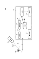
図1は、電磁波位相振幅生成装置100の外観構成の一例を示す図である。[Configuration of electromagnetic wave phase amplitude generator]
FIG. 1 is a diagram showing an example of the appearance configuration of the electromagnetic wave
電磁波位相振幅生成装置100は、照射部RLと、端末装置10とを備える。
照射部RLから照射される電磁波は、撮像対象OBに照射される。撮像対象OBとは、電磁波位相振幅生成装置100によって観察される試料である。具体的には、撮像対象OBとは、不透明及び無色透明な生体試料、非生体試料である材料及び素材などである。ここで、電磁波とは、可視光線、X線、電子線、紫外線、赤外線、テラヘルツ波、ミリ波及びマイクロ波のうち少なくとも1つである。なお、上述した電磁波は、これに限られず、どのような波長の電磁波であってもよい。この一例では、電磁波が可視光線の場合について説明する。以下の説明では、可視光線を単に光と記載する場合もある。また、以下の説明では、照射部RLから照射される光を、照射光REWとも記載する。端末装置10は、撮像対象OBが散乱した散乱光SLを、撮像画像として撮像する。端末装置10とは、この一例ではスマートフォンなどの撮像装置を備える端末である。The electromagnetic wave
The electromagnetic wave emitted from the irradiation unit RL is applied to the image pickup target OB. The imaging target OB is a sample observed by the electromagnetic wave
照射部RLは、照明Lと、散乱板MPとを備える。照射部RLは、分割された領域ごとに照射される電磁波の状態が決められた空間周波数上においてランダムな照射パターンの電磁波を撮像対象に照射する。電磁波の状態とは、電磁波の強度、振幅及び位相の状態である。電磁波の強度及び振幅の状態とは、電磁波の強さの状態のことである。電磁波の位相の状態とは、電磁波の波の遅れや進みの状態のことである。
空間周波数上とは、端末装置10が撮像する撮像画像における空間周波数上である。照明Lから出射される光は、散乱板MPに当たり、散乱板MPの領域ごとに異なる光の散乱率に応じた強さの散乱光を照射光REWとして、散乱板MPから撮像対象OBに対して照射される。The irradiation unit RL includes an illumination L and a scattering plate MP. The irradiation unit RL irradiates the image pickup target with an electromagnetic wave having a random irradiation pattern on a spatial frequency in which the state of the electromagnetic wave to be irradiated for each divided region is determined. The state of the electromagnetic wave is the state of the intensity, amplitude, and phase of the electromagnetic wave. The state of the intensity and amplitude of the electromagnetic wave is the state of the intensity of the electromagnetic wave. The phase state of an electromagnetic wave is the state of delay or advance of an electromagnetic wave wave.
The spatial frequency is on the spatial frequency in the captured image captured by the
具体的には、照明Lは、光を出射する。照明Lから出射される光は、散乱板MPを介して、撮像対象OBに照射される。照明Lとは、位相及び振幅がランダムに変化する光よりも可干渉性が高い光を出射する光源である。つまり、可干渉性が高い光源とは、光源から出射される光の位相及び振幅に相関がある光源である。より具体的には、照明Lとは、レーザー光源、半導体レーザー光源、LED(LIGHT EMITTING DIODE)光源である。 Specifically, the illumination L emits light. The light emitted from the illumination L is applied to the imaging target OB via the scattering plate MP. The illumination L is a light source that emits light having higher coherence than light whose phase and amplitude change randomly. That is, the light source having high coherence is a light source having a correlation with the phase and amplitude of the light emitted from the light source. More specifically, the illumination L is a laser light source, a semiconductor laser light source, and an LED (LIGHT EMITTING DIODE) light source.
散乱板MPには、照明Lから出射された光が照射される。散乱板MPは、照明Lから出射された光を散乱する。散乱板MPは、散乱した光を照射光REWとして、撮像対象OBに対して照射する。散乱板MPとは、照明Lから照射される光の強さを、領域ごとに変える板である。散乱板MPとは、電磁波の強度、電磁波の振幅及び電磁波の位相のうち少なくとも1つを変調する光学素子である。この一例では、散乱板MPとは、空間光変調器である。 The scattering plate MP is irradiated with the light emitted from the illumination L. The scattering plate MP scatters the light emitted from the illumination L. The scattering plate MP irradiates the image pickup target OB with the scattered light as the irradiation light REW. The scattering plate MP is a plate that changes the intensity of the light emitted from the illumination L for each region. The scattering plate MP is an optical element that modulates at least one of the intensity of an electromagnetic wave, the amplitude of an electromagnetic wave, and the phase of an electromagnetic wave. In this example, the scattering plate MP is a spatial light modulator.
散乱板MPは、光を散乱する程度が異なるように分割された領域を備える。ここで、領域とは、撮像対象OBの大きさに応じた大きさの領域である。この一例では、散乱板MPは、領域は正方形に分割された領域である。また、光を散乱する程度が異なるように分割された領域とは、光の散乱率が異なるパターンである。具体的には、散乱板MPとは、電磁波の強さのみをランダムにして電磁波の位相を一定にする散乱板である。なお、散乱板MPは、電磁波の強さを一定にして電磁波の位相のみをランダムにする散乱板であってもよい。散乱板MPは、電磁波の強さと電磁波の位相とをランダムにする散乱板であってもよい。 The scattering plate MP includes regions divided so that the degree of scattering light is different. Here, the region is a region having a size corresponding to the size of the imaging target OB. In this example, the scattering plate MP is a region whose region is divided into squares. Further, the region divided so that the degree of light scattering is different is a pattern in which the light scattering rate is different. Specifically, the scattering plate MP is a scattering plate in which only the intensity of electromagnetic waves is randomized to keep the phase of electromagnetic waves constant. The scattering plate MP may be a scattering plate in which the intensity of the electromagnetic wave is constant and only the phase of the electromagnetic wave is randomized. The scattering plate MP may be a scattering plate that randomizes the intensity of the electromagnetic wave and the phase of the electromagnetic wave.
ここで、本実施形態の一例では、散乱板MPの光の散乱率が異なるパターンとは、撮像対象OBに照射される光が当たる領域のパターンが、空間周波数上において一様にスペクトルが広がるパターンである。言い換えると、散乱板MPの光の散乱率が異なるパターンとは、撮像対象OBに照射される光が当たる領域のパターンが、空間周波数上において原点以外にピークを持たないパターンである。
具体的には、散乱板MPの光の散乱率が異なるパターンとは、空間周波数上においてホワイトノイズ様のパターンである。ホワイトノイズ様とは、概ね周期性が観測しにくいパターンである。つまり、散乱板MPの光の散乱率が異なるパターンは、空間周波数上において全くピークを持たないパターン又は空間周波数上において、均一にスペクトルが広がっているパターンである必要は無い。Here, in an example of the present embodiment, the pattern in which the scattering rate of the light of the scattering plate MP is different is the pattern in which the pattern of the region where the light irradiated to the image pickup target OB hits has a uniformly widened spectrum on the spatial frequency. Is. In other words, the pattern in which the scattering rates of the light of the scattering plate MP are different is a pattern in which the pattern in the region where the light irradiated to the imaging target OB hits has no peak other than the origin on the spatial frequency.
Specifically, the pattern in which the light scattering rate of the scattering plate MP is different is a white noise-like pattern on the spatial frequency. White noise-like is a pattern whose periodicity is generally difficult to observe. That is, the patterns in which the light scattering rates of the scattering plates MP are different need not be a pattern having no peak on the spatial frequency or a pattern in which the spectrum is uniformly spread on the spatial frequency.
端末装置10は、表示部13を備える。端末装置10は、照射光REWが照射された撮像対象OBが散乱した散乱光SLを撮像する。撮像対象OBが散乱した散乱光SLとは、撮像対象OBの信号を示す情報である。端末装置10は、散乱光SLを撮像した撮像画像と、散乱板MPのランダムな照射パターンを示す情報とに基づいて、撮像対象OBからの散乱光SLの少なくとも位相と振幅とを示す情報を生成する。以下の説明では、撮像対象OBからの散乱光SLの少なくとも位相と振幅とを示す情報を、複素振幅情報と記載する場合がある。
The
表示部13は、端末装置10が生成する散乱光SLの少なくとも位相と振幅とを示す情報に基づく、散乱光SLの強度、位相及び振幅を表示する。具体的には、表示部13は、生成部12が生成する複素振幅情報を表示する。また、表示部13は、生成部12が複素振幅情報に基づく再構成された画像の情報を表示する。この一例では、具体的には表示部13とは、液晶ディスプレイである。
The
[電磁波位相振幅生成装置の構成の一例]
次に、図2を参照して、本実施形態に係る電磁波位相振幅生成装置100の構成の一例について説明する。
図2は、電磁波位相振幅生成装置100の機能構成の一例を示す図である。照射部RLと、撮像対象OBとについては、上述した説明と同様である。[Example of configuration of electromagnetic wave phase amplitude generator]
Next, an example of the configuration of the electromagnetic wave
FIG. 2 is a diagram showing an example of the functional configuration of the electromagnetic wave
端末装置10は、操作検出部14と、撮像部11と、画像取得部15と、生成部12と、記憶部16と、表示部13と、を備える。
The
操作検出部14は、電磁波位相振幅生成装置100を操作するユーザからの操作を検出する。具体的には、操作検出部14は、照射部RLから撮像対象OBに対して照射光REWを照射する場合には、ユーザが照射コマンドを操作したことを検出する。ユーザからの照射コマンド検出した操作検出部14は、照射部RLに対して、照射光REWを照射する指令を出力する。
The
撮像部11は、撮像素子(不図示)を備える。撮像素子は、撮像対象OBが散乱した散乱光SLを撮像する。具体的には、撮像素子は、複数の画素を有する。撮像素子は、散乱光SLの振幅又は散乱光SLの強度に応じた電荷を画素にそれぞれ溜める。撮像部11は、撮像素子が溜めた電荷に基づいて、散乱光SLを撮像する。以下の説明では、撮像素子は、横yピクセル、縦xピクセルの画素を有する。撮像対象OBと撮像部11が備える撮像素子との間の距離は、距離zである。撮像部11は、散乱光SLを撮像した撮像画像IPを生成する。撮像部11は、散乱光SLを生成した撮像画像IPを、画像取得部15に対して出力する。以下の説明では、撮像画像IPとは、散乱光SLの強度を示す情報である。
The
画像取得部15は、撮像部11から撮像画像IPを取得する。画像取得部15は、撮像部11から取得した撮像画像IPを、生成部12に対して出力する。
記憶部16には、散乱板MPのランダムな照射パターンを示すパターン情報RPIが記憶される。The
The
生成部12は、撮像部11から撮像画像IPを取得する。生成部12は、記憶部16に記憶されるパターン情報RPIを取得する。
生成部12は、撮像部11が生成する撮像画像IPと、パターン情報RPIと、散乱光SLを示す情報と、に基づいて、撮像対象OBからの散乱光SLの少なくとも位相と振幅とを示す情報を生成する。生成部12は、撮像対象OBのスパース性に基づくスパース拘束演算を行うことにより、位相と振幅とを示す情報を生成する。生成部12が生成する位相と振幅とを示す情報とは、散乱光SLの複素振幅情報である。生成部12は、生成した複素振幅情報に基づいて、散乱光SLの位相を示す情報P及び散乱光SLの振幅を示す情報VAを生成する。The
The
生成部12は、生成した位相と振幅とを示す情報、散乱光SLの位相を示す情報P及び散乱光SLの振幅を示す情報VAを、表示部13に出力する。
表示部13は、生成部12から取得した位相と振幅とを示す情報、散乱光SLの位相を示す情報P及び散乱光SLの振幅を示す情報VAを表示する。The
The
[電磁波位相振幅生成装置の動作の概要]
次に、図3を参照して、電磁波位相振幅生成装置100の動作の概要について説明する。
図3は、電磁波位相振幅生成装置100の動作の一例を示す流れ図である。
照射部RLは、撮像対象OBに対してランダムな照射パターンの電磁波を照射する(ステップS110)。撮像部11は、撮像対象OBが散乱した散乱光SLを、撮像画像IPとして撮像する(ステップS120)。[Outline of operation of electromagnetic wave phase amplitude generator]
Next, the outline of the operation of the electromagnetic wave
FIG. 3 is a flow chart showing an example of the operation of the electromagnetic wave
The irradiation unit RL irradiates the image pickup target OB with electromagnetic waves having a random irradiation pattern (step S110). The
撮像部11は、生成部12に対して、撮像画像IPを出力する。生成部12は、撮像画像IPを取得する。生成部12は、記憶部16から照射パターンを示すパターン情報RPIを取得する。生成部12は、撮像部11から取得した撮像画像IPと、記憶部16から取得したパターン情報RPIとに基づいて、撮像対象OBのスパース性に基づくスパース拘束演算を行うことにより、散乱光SLの位相と振幅とを示す情報を生成する。
The
具体的には、生成部12は、式(1)及び式(2)から、散乱光SLの位相と振幅とを示す情報を生成する。
Specifically, the

式(1)は順問題すなわち数理モデルを使って予測する問題を示す式である。 Equation (1) is an equation showing a forward problem, that is, a problem predicted using a mathematical model.
式(2)は逆問題すなわちデータから数理モデルを推定する問題を示す式である。
式(1)及び式(2)に含まれるx及びyとは、撮像素子が備える画素の数である縦xピクセル及び横yピクセルと対応する数である。以下の数式におけるx及びyも、同様である。Equation (2) is an inverse problem, that is, an equation showing a problem of estimating a mathematical model from data.
The x and y included in the equations (1) and (2) are numbers corresponding to the vertical x pixels and the horizontal y pixels, which are the number of pixels included in the image sensor. The same applies to x and y in the following formulas.
式(1)及び式(2)に含まれる|g|2とは、撮像素子が撮像した撮像画像IPである。具体的には、撮像画像IPとは、散乱光SLの振幅の絶対値を二乗した情報である。
式(1)及び式(2)に含まれるgとは、散乱光SLの位相と振幅とを示す複素振幅情報である。以下の説明では、散乱光SLの位相と振幅とを示す複素振幅情報を、単に複素振幅情報gと記載することがある。より具体的には、gとは、式(3)に示す行列である。以下の数式におけるgも同様である。 | G | 2 included in the formula (1) and the formula (2) is an image captured image IP imaged by the image sensor. Specifically, the captured image IP is information obtained by squaring the absolute value of the amplitude of the scattered light SL.
The g contained in the equations (1) and (2) is complex amplitude information indicating the phase and amplitude of the scattered light SL. In the following description, the complex amplitude information indicating the phase and amplitude of the scattered light SL may be simply referred to as the complex amplitude information g. More specifically, g is a matrix represented by the equation (3). The same applies to g in the following formula.
式(1)及び式(2)に含まれるPzとは、撮像対象OBと、撮像素子との距離zにおけるフレネル伝播のテープリッツ行列である。より具体的には、Pzとは、式(4)に示す行列である。以下の数式におけるPzも同様である。 The Pz included in the equations (1) and (2) is a Fresnel-propagated Toeplitz matrix at a distance z between the image pickup target OB and the image pickup element. More specifically, Pz is a matrix represented by the equation (4). The same applies to Pz in the following formula.
式(1)及び式(2)に含まれるMとは、散乱板MPのパターン情報RPIを示す行列である。具体的には、Mとは、式(5)に示す行列である。以下の数式におけるMも同様である。この一例では、パターン情報RPIとは、照射された光を散乱しない0から、光の強さをそのままにして散乱する1までの数値によって、散乱板MPのパターンを示す情報である。 M included in the equations (1) and (2) is a matrix showing the pattern information RPI of the scattering plate MP. Specifically, M is a matrix represented by the equation (5). The same applies to M in the following formula. In this example, the pattern information RPI is information indicating the pattern of the scattering plate MP by a numerical value from 0 that does not scatter the irradiated light to 1 that scatters the irradiated light as it is.
式(1)及び式(2)に含まれるfとは、撮像対象OBの信号を示す情報である。より具体的には、fとは、式(6)に示す行列である。以下の数式におけるfも同様である。 The f contained in the equations (1) and (2) is information indicating the signal of the image pickup target OB. More specifically, f is a matrix represented by the equation (6). The same applies to f in the following formula.
ここで、式(2)に含まれるl2とは、l2ノルムである。以下の数式におけるl2も、同様である。
式(2)に含まれる、R(f)とは、スパース拘束である。具体的には、R(f)とは、撮像対象OBの信号を示す情報のスパース性に基づく正則である。式(2)に含まれるτとは、正則のためのパラメータである。以下の数式におけるR(f)及びτも同様である。
つまり、生成部12は、撮像対象OBのスパース性に基づくスパース拘束演算を行うことにより、散乱光SLの複素振幅情報gを生成する(ステップS130)。なお、生成部12は、スパース拘束演算を公知の手法によって生成する。例えば、生成部12は、公知のスパースソルバーを用いてスパース拘束演算を行う。Here, l2 included in the equation (2) is the l2 norm. The same applies to l2 in the following formula.
R (f) included in the formula (2) is a sparse constraint. Specifically, R (f) is a regularity based on the sparsity of the information indicating the signal of the image pickup target OB. Τ included in the equation (2) is a parameter for regularity. The same applies to R (f) and τ in the following formulas.
That is, the
生成部12は、生成した複素振幅情報gに基づいて、散乱光SLの強度を再構成する。
具体的には、生成部12は、生成した複素振幅情報gの絶対値の二乗から散乱光SLの強度を示す情報を再構成する。生成部12は、再構成した散乱光SLの強度を示す情報と、撮像部11が撮像対象OBを撮像した撮像画像とを比較する(ステップS140)。再構成した散乱光SLの強度を示す情報と、撮像部11が撮像対象OBを撮像した撮像画像とが近似する場合には、処理を終了する(ステップS140;YES)。再構成した散乱光SLの強度を示す情報と、撮像部11が撮像対象OBを撮像した撮像画像とが近似しない場合には、生成した複素振幅情報gを、式(1)及び式(2)に代入して、ステップS130の処理を繰り返す(ステップS140;NO)。なお、生成部12は、再構成した散乱光SLの強度を示す情報と、撮像部11が撮像対象OBを撮像した撮像画像とを比較する方法は、公知の技術を用いてもよい。また、再構成した散乱光SLの強度を示す情報と、撮像部11が撮像対象OBを撮像した撮像画像とを比較する方法は、ユーザの目視によって、近似しているか否かを判断してもよい。The
Specifically, the
[電磁波位相振幅生成装置の動作の具体例]
ここまでは、生成部12の動作の概要について説明した。生成部12は、式(1)及び式(2)を解くことにより、複素振幅情報gを生成する。電磁波位相振幅生成装置100は、式(1)及び式(2)を解く場合には、式(1)に示す順問題が非線形問題であり、容易に解くことができない場合がある。
ここで、複素振幅情報gを生成する方法の一例について説明する。[Specific example of operation of electromagnetic wave phase amplitude generator]
Up to this point, the outline of the operation of the
Here, an example of a method for generating complex amplitude information g will be described.
[補助平面による解法]
以下の説明では、生成部12は、オルタネイティングプロジェクションによって、複素振幅情報gを生成する。
生成部12は、補助平面aを、撮像対象OBと、撮像素子との間に設定する。補助平面aを仮定すると、式(1)は、式(7)及び式(8)によって表現することができる。[Solution by auxiliary plane]
In the following description, the
The
ここで、式(7)に含まれるz1とは、撮像対象OBと、補助平面aとの距離である。
式(7)に含まれるZ2とは、補助平面aと、撮像素子との距離である。距離z1と、距離z2とを加算すると、撮像対象OBと撮像素子との距離zである。つまり、補助平面aとは、撮像対象OBから距離z1及び撮像素子から距離z2離れた位置に仮定される複素振幅情報である。Here, z1 included in the equation (7) is the distance between the image pickup target OB and the auxiliary plane a.
Z2 included in the formula (7) is the distance between the auxiliary plane a and the image sensor. When the distance z1 and the distance z2 are added, the distance z between the image pickup target OB and the image pickup element is obtained. That is, the auxiliary plane a is complex amplitude information assumed at a distance z1 from the image pickup target OB and a distance z2 from the image pickup element.
式(8)とは、撮像対象OBと、補助平面aとの距離がz1の場合の式である。式(8)に示すように、補助平面aは、線形問題を解くことにより生成する。 The formula (8) is a formula when the distance between the image pickup target OB and the auxiliary plane a is z1. As shown in the equation (8), the auxiliary plane a is generated by solving the linear problem.
なお、補助平面aは、後程説明する式(9)から生成される仮置きのgを逆フレネル変換することにより、生成される。つまり、生成部12は、位相推定問題を解くことにより、複素振幅情報gを生成することができる。
The auxiliary plane a is generated by performing an inverse Fresnel transformation of the temporarily placed g generated from the equation (9) described later. That is, the
生成部12は、初期値として、複素振幅情報gに仮の値を設定する。初期値としての複素振幅情報gの仮の値は、どの様な値であってもよい。生成部12は、仮の値を設定した補助平面gを、式(9)に代入する。生成部12は、式(9)を、G−S法によって仮置きのgを生成する。G−S法とは、反復型位相推定法である。
The
式(10)とは、式(9)を変形した式である。生成部12は、式(10)によって、仮置きのgを生成する。なお、式(10)に示すように、生成部12は、撮像画像IPを、距離z2の位置での複素振幅情報及び補助平面aの強度によって要素単位で除算する。
生成部12は、要素単位で除算した値を1/2乗した値と、距離z2の位置での複素振幅情報及び補助平面aを要素単位で乗算することにより、仮置きのgを生成する。生成部12は、生成した仮置きのgを、逆フレネル変換することにより、仮置きの補助平面aを生成する。The equation (10) is a modified equation of the equation (9). The
The
生成部12は、式(10)から生成された仮置きの補助平面aを、式(11)に代入する。生成部12は、式(11)を、TwIST法によって解くことにより、仮置きのfを生成する。TwIST法とは、圧縮センシングの一般的な解法である。
生成部12は、仮置きのfを伝播させる。生成部12は、伝播させた仮置きのfを初期値として、式(10)から補助平面aを生成する。
つまり、生成部12は複素振幅情報gの初期値にランダムな値を代入して、G−S法により補助平面aを生成する。生成部12は、生成した補助平面aを式(11)に代入し、仮置きのfをTwIST法により生成する。生成部12は、生成した仮置きのfを式(10)に代入し、ランダムな値よりも精度がよい仮置きのgを生成する。
生成部12は、上述した処理を、仮置きのgから再構成した散乱光SLの強度を示す情報と、撮像部11が撮像対象OBを撮像した撮像画像とが近似するまで繰り返す。The
The
That is, the
The
なお、式(1)及び式(2)を解く方法は、上述したG−S法及びTwIST法のオルタネイティングプロジェクションによる方法に限られない。 The method of solving the equations (1) and (2) is not limited to the above-mentioned method by the alternate projection of the GS method and the TwIST method.
[電磁波位相振幅生成装置が生成した撮像対象からの散乱光の位相と振幅とを示す情報の一例]
次に、図4から図6を参照して、電磁波位相振幅生成装置100が生成する複素振幅情報gの一例について説明する。
図4は、散乱光SLの振幅を示す情報VAと散乱光SLの位相を示す情報Pとの一例を示す図である。
図4(a)は、散乱光SLの振幅を示す情報VAの一例である。
図4(b)は、散乱光SLの位相を示す情報Pの一例である。この一例では、実験のため、位相を示す情報Pは、元の位相を90度回転させた位相である。[Example of information indicating the phase and amplitude of scattered light from an imaging target generated by the electromagnetic wave phase amplitude generator]
Next, an example of the complex amplitude information g generated by the electromagnetic wave
FIG. 4 is a diagram showing an example of information VA indicating the amplitude of the scattered light SL and information P indicating the phase of the scattered light SL.
FIG. 4A is an example of the information VA showing the amplitude of the scattered light SL.
FIG. 4B is an example of information P indicating the phase of the scattered light SL. In this example, for the sake of experimentation, the information P indicating the phase is the phase obtained by rotating the original phase by 90 degrees.
次に、図5は、散乱板MPと、撮像画像IPとの一例を示す図である。
図5(a)は、散乱板MPと、散乱板MPの一部を拡大した散乱板MPEとの一例である。散乱板MPは、空間周波数上においてランダムなパターンである。つまり、散乱板MPのパターンを、フーリエ変換すると、空間周波数上でのピークが周期的に発生していないパターンである。
図5(b)は、撮像対象OBが散乱した散乱光SLを撮像部11が撮像した撮像画像IPの一例である。Next, FIG. 5 is a diagram showing an example of the scattering plate MP and the captured image IP.
FIG. 5A is an example of the scattering plate MP and the scattering plate MPE in which a part of the scattering plate MP is enlarged. The scattering plate MP is a random pattern on the spatial frequency. That is, when the pattern of the scattering plate MP is Fourier transformed, it is a pattern in which peaks on the spatial frequency do not occur periodically.
FIG. 5B is an example of the captured image IP in which the
次に、図6は、生成部12が生成する位相と振幅とを示す情報gから生成される情報の一例を示す図である。
図6(a)は、生成部12が生成した振幅を示す情報から生成される強度RVAの一例を示す図である。図6(a)と、図4(a)とを比較すると、生成部12は、散乱光SLの振幅を示す情報VAと近似する振幅情報を生成することがわかる。
図6(b)は、生成部12が生成した位相を示す情報RPの一例を示す図である。図6(b)と、図4(b)とを比較すると、生成部12は、散乱光SLの位相を示す情報Pと近似する位相情報を生成することがわかる。Next, FIG. 6 is a diagram showing an example of information generated from the information g indicating the phase and amplitude generated by the
FIG. 6A is a diagram showing an example of the intensity RVA generated from the information indicating the amplitude generated by the
FIG. 6B is a diagram showing an example of an information RP showing the phase generated by the
[まとめ]
以上説明したように、電磁波位相振幅生成装置100は、照射部RLと、撮像部11と、生成部12とを備える。撮像部11は、照射部RLから照射される照射光REWを、撮像対象OBが散乱した散乱光SLを撮像する。生成部12は、撮像部11が撮像した撮像画像IPと、パターン情報RPIと、撮像対象OBの信号を示す情報fとに基づいて、撮像対象OBのスパース性に基づくスパース拘束演算を行うことにより、複素振幅情報gを生成する。電磁波位相振幅生成装置100は、散乱光SLを直接、撮像素子によって検出することができ、信号雑音比を高めることができる。また電磁波位相振幅生成装置100は、散乱光SLを直接、撮像素子によって検出することができるため、散乱光SLを直接、撮像素子によって検出しない場合と比較して、照射部RLから出射される光の強さを抑えることができる。つまり、電磁波位相振幅生成装置100は、撮像対象への侵襲性を小さくすることができる。[summary]
As described above, the electromagnetic wave
電磁波位相振幅生成装置100は、複素振幅情報gを生成することができるため、撮像対象OBの厚みや、電磁波の屈折率の分布情報を得ることができる。電磁波位相振幅生成装置100は、撮像対象OBの厚みや電磁波の屈折率の分布情報を得ることができるため、定量性がある情報を、複素振幅情報gから算出できる。
Since the electromagnetic wave
電磁波位相振幅生成装置100は、一度の撮像による撮像画像IPと、ランダムな照射パターンを示すパターン情報RPIとに基づいて、複素振幅情報gを生成することができるため、電磁波に弱い撮像対象OBを傷めずに、複素振幅情報gを生成することができる。また、電磁波位相振幅生成装置100は、一度の撮像による撮像画像IPと、ランダムな照射パターンを示すパターン情報RPIとに基づいて、複素振幅情報gを生成することができるため、動く撮像対象OBの場合にも、複素振幅情報gを生成することができる。
Since the electromagnetic wave
生成部12は、生成した電磁波の少なくとも位相と振幅とを示す情報gと撮像対象OBの信号を示す情報とに基づいて、電磁波の少なくとも位相と振幅とを示す情報gを生成することを繰り返しおこなう。生成部12は、複素振幅情報gの生成を繰り返すことにより、非線形問題を、線形問題にすることができ、電磁波の少なくとも位相と振幅とを示す情報gを生成することができる。
The
上述した、照射部RLが照射するランダムなパターンが、空間周波数上において一様にスペクトルが広がるパターンである場合には、電磁波位相振幅生成装置100は、照射部RLから照射光REWが照射される全ての面において、良好に散乱光SLの複素振幅情報gを生成することができる。
When the random pattern irradiated by the irradiation unit RL described above is a pattern in which the spectrum spreads uniformly on the spatial frequency, the electromagnetic wave
また、電磁波とは、可視光線、X線、電子線、紫外線、赤外線、テラヘルツ波、ミリ波及びマイクロ波のうち少なくとも1つである。電磁波位相振幅生成装置100は、レンズを必要としない構成のため、従来、レンズを作ることが困難な、X線、電子線、紫外線、赤外線及びテラヘルツ波などの電磁波の位相と振幅とを示す情報を生成することができる。また、電磁波位相振幅生成装置100は、レンズを必要としない構成のため、電磁波位相振幅生成装置100の筐体の大きさを小さく構成することができる。
The electromagnetic wave is at least one of visible light, X-ray, electron beam, ultraviolet ray, infrared ray, terahertz wave, millimeter wave and microwave. Since the electromagnetic wave
上述した、散乱板MPが撮像対象OBごとに複数種類存在する場合には、記憶部16には、散乱板MPの種類ごとにパターン情報RPIが記憶される。この場合には、生成部12は、操作検出部14が検出するユーザからの操作によって、読み出すパターン情報RPIを選択する。
When there are a plurality of types of the scattering plate MP described above for each type of the imaging target OB, the
上述した説明では、生成部12がスパース拘束演算をして複素振幅情報gを生成する場合について説明したが、複素振幅情報gは、他の装置が演算してもよい。他の装置とは、ネットワーク上のサーバが稼働するウェブサービスなどである。この場合には、生成部12は、複素振幅情報gを生成するために必要な情報を他の装置に出力する。生成部12は、他の装置が生成した複素振幅情報gを取得すればよい。
In the above description, the case where the
[第2の実施形態]
図7を参照して、本実施形態に係る電磁波位相振幅生成装置100−1の構成の一例について説明する。
図7は、電磁波位相振幅生成装置100−1の構成の一例を示す図である。本実施形態に係る電磁波位相振幅生成装置100−1は、撮像対象OBを三次元撮像できる点において、上述した電磁波位相振幅生成装置100と異なる。なお、第1の実施形態と同様の構成については同一の符号を付してその説明を省略する。[Second Embodiment]
An example of the configuration of the electromagnetic wave phase amplitude generator 100-1 according to the present embodiment will be described with reference to FIG. 7.
FIG. 7 is a diagram showing an example of the configuration of the electromagnetic wave phase amplitude generator 100-1. The electromagnetic wave phase amplitude generator 100-1 according to the present embodiment is different from the electromagnetic wave
電磁波位相振幅生成装置100−1は、散乱光SLの複数距離の波面の状態に基づいて撮像対象OBのスパース性に基づくスパース拘束演算を行うことにより、散乱光SLの位相と振幅とを示す情報を生成する。ここで、散乱光SLの複数距離の波面とは、散乱光SLの波面のうち、散乱光SLの進行方向に互いに離れている複数の波面をいう。一例として、散乱光SLの複数距離の波面とは、ある瞬間において、撮像部11からの距離が互いに異なる波面をいう。
具体的には、記憶部16には、パターン情報RPIが記憶されている。本実施形態のパターン情報RPIは、散乱光SLの複数距離の波面の状態を示す距離毎波面パターン情報を含んでいる。つまり、記憶部16には、距離毎波面パターン情報を含むパターン情報RPIが記憶されている。
生成部12は、撮像部11から取得した撮像画像IPと、記憶部16から取得したパターン情報RPIとに基づいて、撮像対象OBのスパース性に基づくスパース拘束演算を行うことにより、散乱光SLの位相と振幅とを示す情報を生成する。ここで、本実施形態の生成部12は、パターン情報RPIに含まれる距離毎波面パターン情報に基づいて、散乱光SLの波面毎に撮像対象OBのスパース性に基づくスパース拘束演算を行う。The electromagnetic wave phase amplitude generator 100-1 performs a sparse constraint calculation based on the sparseness of the imaging target OB based on the state of the wave surface of the scattered light SL at a plurality of distances, thereby indicating the phase and amplitude of the scattered light SL. To generate. Here, the multi-distance wave planes of the scattered light SL refer to a plurality of wave planes of the scattered light SL that are separated from each other in the traveling direction of the scattered light SL. As an example, the multi-distance wave surface of the scattered light SL means a wave surface in which the distances from the
Specifically, the pattern information RPI is stored in the
The
ここで、撮像部11が撮像する散乱光SLの各波面には、撮像対象OBの各断層面の情報が含まれている。生成部12は、散乱光SLの波面毎にスパース拘束演算を行うことにより、撮像対象OBの各断層面の位相と振幅とを示す情報を生成する。
電磁波位相振幅生成装置100−1は、生成部12が生成する撮像対象OBの各断層面の位相と振幅とを示す情報、つまり、撮像対象OBの三次元構造を示す情報を生成することができる。Here, each wave surface of the scattered light SL imaged by the
The electromagnetic wave phase amplitude generator 100-1 can generate information indicating the phase and amplitude of each tomographic surface of the imaging target OB generated by the
電磁波位相振幅生成装置100−1による撮像対象OBの各断層面の位相と振幅とを示す情報の生成結果の一例を図8及び図9に示す。
図8は、生成部12が生成する撮像対象OBの振幅断層画像の一例である。
図9は、生成部12が生成する撮像対象OBの位相断層画像の一例である。
この図8及び図9は、撮像対象OBがボルボックスである場合の一例を示す。図8及び図9に示すように、電磁波位相振幅生成装置100−1によれば、撮像部11の光軸AX方向の位置を様々に変えた断層画像を生成することができる。また、電磁波位相振幅生成装置100−1によれば、この断層画像を再構成することにより、撮像対象OBの三次元構造を示す画像を得ることができる。8 and 9 show an example of the generation result of information indicating the phase and amplitude of each tomographic surface of the image-imaging target OB by the electromagnetic wave phase amplitude generator 100-1.
FIG. 8 is an example of an amplitude tomographic image of the imaging target OB generated by the
FIG. 9 is an example of a phase tomographic image of the imaging target OB generated by the
8 and 9 show an example in which the imaging target OB is a volvox. As shown in FIGS. 8 and 9, according to the electromagnetic wave phase amplitude generator 100-1, it is possible to generate a tomographic image in which the position of the
[第3の実施形態]
図10から図23を参照して、本実施形態に係る電磁波位相振幅生成装置100−2の構成の一例について説明する。本実施形態に係る電磁波位相振幅生成装置100−2は、撮像部11の解像度が比較的低い場合においても、高解像度の位相と振幅とを示す情報を得ることができる点において、上述した電磁波位相振幅生成装置100及び電磁波位相振幅生成装置100−1と異なる。なお、上述した各実施形態と同様の構成については同一の符号を付してその説明を省略する。[Third Embodiment]
An example of the configuration of the electromagnetic wave phase amplitude generator 100-2 according to the present embodiment will be described with reference to FIGS. 10 to 23. The electromagnetic wave phase amplitude generator 100-2 according to the present embodiment has the above-mentioned electromagnetic wave phase in that information indicating a high-resolution phase and amplitude can be obtained even when the resolution of the
図10は、電磁波位相振幅生成装置100−2の構成の一例を示す図である。
図11は、電磁波位相振幅生成装置100−2の構成の他の一例を示す図である。
本実施形態の一例において、撮像部11の解像度が、生成部12によるスパース拘束演算の解像度よりも解像度が低いとは、撮像部11の撮像素子の画素数が比較的少ないことをいう。例えば、撮像部11の解像度が低いとは、撮像部11の撮像素子の画素数が、散乱板MPのパターンの空間周波数を解像可能な程度の画素数よりも少ないことをいう。ここで、散乱率が互いに異なる散乱板MP上の各領域1つ1つを「散乱板MPの散乱区画SC」と称するとすると、撮像部11の解像度が低いとは、撮像部11の撮像素子の画素数が、散乱板MPの散乱区画数よりも少ないことをいう。
また、「撮像部11の撮像素子の画素数が、散乱板MPの散乱区画数よりも少ないこと」とは、式(1)及び式(2)に含まれる|g|2(すなわち、撮像画像IP)の行列の大きさが、同式に含まれるM(すなわち、散乱板MPのパターン情報RPI)の行列の大きさに比べて小さいことを意味する。FIG. 10 is a diagram showing an example of the configuration of the electromagnetic wave phase amplitude generator 100-2.
FIG. 11 is a diagram showing another example of the configuration of the electromagnetic wave phase amplitude generator 100-2.
In an example of the present embodiment, the resolution of the
Further, "the number of pixels of the image sensor of the
図10には、符号化開口型回折イメージングの構成の一例を示す。この一例の構成の場合、撮像対象OBから出射される物体光OLが散乱板MPに入射する。この物体光OLに応じた散乱光SLが散乱板MPから出射され、出射された散乱光SLが撮像部11に入射する。つまり、この一例の構成の場合、散乱板MPが撮像対象OBと撮像部11との間に配置される。
同図には、撮像部11の撮像素子の画素PXの数と、散乱板MPの散乱区画SCの数との比が、1:4である場合を示す。すなわち、同図の例では、撮像部11の撮像素子の画素PXの数が、散乱板MPの散乱区画SCの数よりも少ない。FIG. 10 shows an example of the configuration of coded aperture type diffraction imaging. In the case of the configuration of this example, the object light OL emitted from the image pickup target OB is incident on the scattering plate MP. The scattered light SL corresponding to the object light OL is emitted from the scattering plate MP, and the emitted scattered light SL is incident on the
The figure shows a case where the ratio of the number of pixels PX of the image sensor of the
図11には、符号化照明型回折イメージングの構成の一例を示す。この一例の構成の場合、散乱板MPから照射光REWが出射され、出射された照射光REWが撮像対象OBに照射される。撮像対象OBに照射光REWが照射されるとこの照射光REWに応じた散乱光SLが撮像対象OBから出射され、出射された散乱光SLが撮像部11に入射する。つまり、この一例の構成の場合、撮像対象OBが散乱板MPと撮像部11との間に配置される。
同図の一例の場合においても、図10に示す一例と同様に、撮像部11の撮像素子の画素PXの数と、散乱板MPの散乱区画SCの数との比が、1:4である。すなわち、同図の例においても、撮像部11の撮像素子の画素PXの数が、散乱板MPの散乱区画SCの数よりも少ない。FIG. 11 shows an example of the configuration of coded illumination type diffraction imaging. In the case of the configuration of this example, the irradiation light REW is emitted from the scattering plate MP, and the emitted irradiation light REW is irradiated to the imaging target OB. When the imaging target OB is irradiated with the irradiation light REW, the scattered light SL corresponding to the irradiation light REW is emitted from the imaging target OB, and the emitted scattered light SL is incident on the
In the case of the example of FIG. 10, the ratio of the number of pixels PX of the image sensor of the
なお、撮像部11の撮像素子の画素PXの数と、散乱板MPの散乱区画SCの数との比は、いわゆるビニングによって可変にされていてもよい。ここで、ビニングとは、撮像素子の画素PXのうち、いくつかの画素PXをひとまとめにして1画素として撮像動作を行うことである。一例として、撮像部11の撮像素子の画素PXについて2×2ビニングを行うと、ビニング後の画素数がビニング前の1/4になる。例えば、撮像部11の撮像素子の画素PXの数と、散乱板MPの散乱区画SCの数とが一致している場合において2×2ビニングを行うと、撮像素子のビニング後の画素PXの数と、散乱板MPの散乱区画SCの数との比が、1:4になる。本実施形態の撮像部11は、撮像対象OBの種類や大きさに応じた、又は得たい解像度や処理速度に応じたビニングが可能にされていてもよい。
以下、この図10と図11とに示す構成例のうち、図11に示す符号化照明型回折イメージングの場合を一例にして説明する。The ratio of the number of pixels PX of the image sensor of the
Hereinafter, among the configuration examples shown in FIGS. 10 and 11, the case of the coded illumination type diffraction imaging shown in FIG. 11 will be described as an example.
第1の実施形態において説明したように、生成部12は、式(1)及び式(2)に示す演算により、すなわち、散乱板MPのパターン情報RPIに基づいてスパース拘束演算を行うことにより、散乱光SLの位相と振幅とを示す情報を生成する。
本実施形態においては、撮像部11の撮像素子の画素数が散乱板MPの散乱区画数よりも少ない。この場合、式(1)及び式(2)に含まれる|g|2の行列の大きさと、同式に含まれるMの行列の大きさとが一致しない。なお、ここでいう行列の大きさとは、例えば、行列の行数及び列数のことである。このように、式(1)及び式(2)に含まれる|g|2の行列の大きさと、同式に含まれるMの行列の大きさとが不一致の場合には、2つの行列の対応関係に基づいて、散乱光SLの位相と振幅とを生成する演算を行う。これら2つの行列の大きさが不一致の場合、例えば、2つの行列の大きさを一致させることにより、散乱光SLの位相と振幅とを生成する演算を行う。As described in the first embodiment, the
In the present embodiment, the number of pixels of the image sensor of the
このように2つの行列の大きさが不一致である場合に、2つの行列の大きさを一致させる手順には、例えば、
(手順1:従来の手順)撮像部11が撮像した撮像画像IPを補間(例えば、線形補間)することにより、散乱光SLの位相と振幅とを生成する。
(手順2:本実施形態の手順)撮像部11が撮像した撮像画像IPを補間せずに、散乱光SLの位相と振幅とを生成する。
の2通りがある。本実施形態の生成部12は、(手順2)を採用する。When the sizes of the two matrices do not match in this way, the procedure for matching the sizes of the two matrices includes, for example,
(Procedure 1: Conventional procedure) The phase and amplitude of the scattered light SL are generated by interpolating (for example, linear interpolation) the captured image IP captured by the
(Procedure 2: Procedure of the present embodiment) The phase and amplitude of the scattered light SL are generated without interpolating the captured image IP captured by the
There are two ways. The
ここで、(手順1)の場合には、|g|2の行列の要素を補間(例えば、線形補間)しつつ行列の大きさを拡大することにより、2つの行列の大きさを一致させる。この(手順1)の場合には、撮像部11が撮像した撮像画像IPには含まれていない情報が、補間によって生成される。Here, in the case of (Procedure 1), the sizes of the two matrices are matched by expanding the size of the matrix while interpolating (for example, linear interpolation) the elements of the matrix of | g | 2. In the case of this (procedure 1), information not included in the captured image IP captured by the
一方、上述した(手順2)による場合、すなわち本実施形態の生成部12は、式(1)及び式(2)に含まれる|g|2の要素を補間せずに演算を行う。具体的には、本実施形態の記憶部16には、|g|2の行列の各要素(すなわち、撮像部11の画素)と、Mの行列の各要素(すなわち、散乱板MPの画素)との対応関係が記憶されている。生成部12は、記憶部16に記憶されているこの対応関係に基づいて、撮像画像IPの画素値を、Mの行列の各要素に対応付けることにより、散乱光SLの位相と振幅とを生成する。この|g|2の行列の各要素と、Mの行列の各要素との対応関係とは、撮像部11の解像度と生成部12によるスパース拘束演算の解像度との対応関係の一例である。
この(手順2)の場合、すなわち本実施形態の生成部12によれば、撮像画像IPに対する補間を行わないため、撮像部11が撮像した撮像画像IPには含まれていない情報が生成されない。On the other hand, in the case of the above-mentioned (procedure 2), that is, the
In the case of this (procedure 2), that is, according to the
[実験結果の一例]
本実施形態の電磁波位相振幅生成装置100−2による振幅画像及び位相画像の生成実験の結果の一例について、図12から図23を参照して説明する。まず、図12から図17を参照して振幅画像についての実験結果の一例を説明する。次に、図18から図23を参照して位相画像についての実験結果の一例を説明する。[Example of experimental results]
An example of the result of the amplitude image and the phase image generation experiment by the electromagnetic wave phase amplitude generator 100-2 of the present embodiment will be described with reference to FIGS. 12 to 23. First, an example of the experimental result for the amplitude image will be described with reference to FIGS. 12 to 17. Next, an example of the experimental result for the phase image will be described with reference to FIGS. 18 to 23.
[振幅画像についての実験結果の一例]
図12は、撮像画像IPの画素数の比較の一例を示す図である。図12(A)は、撮像部11の撮像素子の画素数が、散乱板MPの散乱区画数と一致している場合の撮像部11による撮像画像IP(画像PIC1)の一例を示す。図12(B)は、撮像部11の撮像素子の画素数が、散乱板MPの散乱区画数よりも少ない場合の撮像部11による撮像画像IP(画像PIC2)の一例を示す。ここでは、撮像対象OBがワイヤー(細い金属線)である。この一例では、撮像対象OBであるワイヤーの位置が周期的に移動する。したがって、この一例では撮像画像IPに撮像されているワイヤーの位置は、撮像タイミングによって互いに異なっている。
この一例に示すように、撮像素子の画素数が散乱板MPの散乱区画数よりも少ない場合(図12(B))には、撮像素子の画素数が散乱板MPの散乱区画数と一致している場合(同図(A))に比べて撮像画像IPの画素どうしの間隔が大きい。すなわち、撮像素子の画素数が、散乱板MPの散乱区画数よりも少ない場合には、撮像画像IPの解像度が低い。[Example of experimental results for amplitude images]
FIG. 12 is a diagram showing an example of comparison of the number of pixels of the captured image IP. FIG. 12A shows an example of an image image IP (image PIC1) captured by the
As shown in this example, when the number of pixels of the image pickup device is smaller than the number of scattering sections of the scattering plate MP (FIG. 12B), the number of pixels of the image pickup element matches the number of scattering sections of the scattering plate MP. The distance between the pixels of the captured image IP is larger than that in the case of ((A) in the figure). That is, when the number of pixels of the image pickup device is smaller than the number of scattering sections of the scattering plate MP, the resolution of the captured image IP is low.
図13は、撮像素子の画素数が散乱板MPの散乱区画数と一致している場合の散乱光SLの振幅画像及び位相画像の一例を示す図である。図13(A)は、撮像素子の画素数が散乱板MPの散乱区画数と一致している場合の、散乱光SLの振幅画像(画像PIC3)の一例である。図13(B)は、撮像素子の画素数が散乱板MPの散乱区画数と一致している場合の、散乱光SLの位相画像(画像PIC4)の一例である。同図は、撮像部11の撮像素子の画素数が比較的多い場合、すなわち解像度が高い場合における散乱光SLの振幅画像及び位相画像を示している。
FIG. 13 is a diagram showing an example of an amplitude image and a phase image of the scattered light SL when the number of pixels of the image pickup element matches the number of scattering sections of the scattering plate MP. FIG. 13A is an example of an amplitude image (image PIC3) of the scattered light SL when the number of pixels of the image sensor matches the number of scattered sections of the scattering plate MP. FIG. 13B is an example of a phase image (image PIC4) of the scattered light SL when the number of pixels of the image sensor matches the number of scattered sections of the scattering plate MP. The figure shows an amplitude image and a phase image of scattered light SL when the number of pixels of the image sensor of the
図14は、撮像素子の画素数が散乱板MPの散乱区画数よりも少ない場合における、生成部12による散乱光SLの振幅画像及び位相画像の一例を示す図である。すなわち、同図は、撮像部11の撮像素子の画素数が比較的少ない場合、つまり解像度が低い場合における散乱光SLの振幅画像(画像PIC5)及び位相画像(画像PIC6)を示している。生成部12は、上述した(手順2)によって散乱光SLの振幅画像及び位相画像を生成する。より具体的には、生成部12は、式(1)及び式(2)に含まれる|g|2の行列の各要素(すなわち、撮像部11の画素)と、Mの行列の各要素(すなわち、散乱板MPの散乱区画SC)との対応関係に基づいて撮像画像IPの画素値をMの行列の各要素に対応付けることにより、散乱光SLの位相と振幅とを生成する。つまり、生成部12は、|g|2の要素の補間をしない。図14(A)は、|g|2の要素の補間をしなかった場合の散乱光SLの振幅画像の一例である。図14(B)は、|g|2の要素の補間をしなかった場合の散乱光SLの位相画像の一例である。
撮像部11の解像度が比較的低い場合(図14に示す場合)であっても、撮像部11の解像度が比較的高い場合(図13に示す場合)と同等の解像度の振幅画像及び位相画像が得られている。FIG. 14 is a diagram showing an example of an amplitude image and a phase image of the scattered light SL by the
Even when the resolution of the
ここで比較対象として、上述した(手順1)、すなわち従来手法による演算結果の一例を図15に示す。
図15は、従来手法による散乱光SLの振幅画像(画像PIC7)及び位相画像(画像PIC8)の一例を示す図である。従来手法によると、振幅画像及び位相画像ともに、本実施形態の生成部12による場合(図14の場合)に比べて解像度が低い。Here, as a comparison target, FIG. 15 shows an example of the above-mentioned (procedure 1), that is, the calculation result by the conventional method.
FIG. 15 is a diagram showing an example of an amplitude image (image PIC7) and a phase image (image PIC8) of scattered light SL by a conventional method. According to the conventional method, both the amplitude image and the phase image have lower resolutions than the case of the
本実施形態の場合、撮像部11の撮像素子の画素数が散乱板MPの散乱区画数よりも少ない。つまり、本実施形態の場合、撮像部11の解像度が散乱板MPの空間周波数に対して低い。このため、仮に、撮像部11が撮像した撮像画像IPを1フレームだけ使用して、生成部12が振幅画像や位相画像を生成する場合には、生成された画像の解像度は低くなってしまう。
しかしながら、上述したように、本実施形態の生成部12は、複数フレームの撮像画像IPを使用して、振幅画像や位相画像を繰り返し生成する。これら複数フレームのそれぞれの撮像画像IPには、撮像対象OBが撮像されている。これら複数の撮像画像IPにそれぞれ撮像されている撮像対象OBは、フレーム毎に互いに異なる。つまり、これら複数の撮像画像IPには、撮像対象OBの互いに異なる情報が含まれている。
生成部12は、撮像画像IPに含まれる撮像対象OBの情報をフレーム毎に繰り返し取得することにより、撮像対象OBについて、1フレームの撮像画像IPから得られる情報よりも多くの情報を取得することができる。これにより、生成部12は、撮像部11の解像度を超える解像度の振幅画像や位相画像を生成することができる。In the case of this embodiment, the number of pixels of the image sensor of the
However, as described above, the
The
ここで、一般的に、撮像素子は、撮像された画像の画素値を示す信号を画素毎に出力する。この画素値を示す信号の出力時間が画素毎に一定である場合、撮像素子の画素数が少ない場合には、画素数が多い場合に比べて撮像素子の全画素からの信号の出力時間が短い。つまり、画素数が少ない場合には、画素数が多い場合に比べて撮像動作をより高速にすることができる。 Here, in general, the image pickup device outputs a signal indicating the pixel value of the captured image for each pixel. When the output time of the signal indicating this pixel value is constant for each pixel, when the number of pixels of the image pickup element is small, the output time of the signal from all the pixels of the image pickup element is shorter than when the number of pixels is large. .. That is, when the number of pixels is small, the imaging operation can be made faster than when the number of pixels is large.
図16は、時系列に生成された振幅画像及び位相画像の一例を示す図である。図16(A)は、図12(A)に示した条件において、すなわち撮像部11の撮像素子の画素数が散乱板MPの散乱区画数と一致している場合において生成された振幅画像及び位相画像の一例を示す。図16(B)及び図16(C)は、いずれも図12(B)に示した条件において、すなわち撮像部11の撮像素子の画素数が散乱板MPの散乱区画数よりも少ない場合において生成された振幅画像及び位相画像の一例を示す。ここで、図16(B)は、上述した(手順1)すなわち従来の手順によって生成された振幅画像及び位相画像の一例を示す。図16(C)は、上述した(手順2)すなわち本実施形態の生成部12が採用する手順によって生成された振幅画像及び位相画像の一例を示す。
FIG. 16 is a diagram showing an example of an amplitude image and a phase image generated in time series. 16 (A) shows the amplitude image and the phase generated under the conditions shown in FIG. 12 (A), that is, when the number of pixels of the image sensor of the
上述したように、本実施形態の撮像部11の解像度は、生成部12によるスパース拘束演算の解像度よりも解像度が低い。つまり、本実施形態の撮像部11の画素数は、散乱板MPの散乱区画数よりも少ない。換言すれば、撮像部11の撮像素子の画素数は、撮像素子の画素数が散乱板MPの散乱区画数と一致している場合に比べて少ない。本実施形態の撮像部11は、撮像素子の画素数が散乱板MPの散乱区画数と一致している場合(図16(A))に比べて、撮像動作が高速化される(図16(C))。
As described above, the resolution of the
また、本実施形態の撮像部11の解像度は、上述した(手順2)によって振幅画像及び位相画像を生成する。一方、従来手法である(手順1)による場合には、上述したように、撮像部11が撮像した撮像画像IPには含まれていない情報が、補間によって生成される。この撮像画像IPには含まれていない情報は、上述した式(1)及び式(2)による演算においては雑音(ノイズ)成分に相当する。したがって、従来手法である(手順1)によって生成された振幅画像及び位相画像(図16(B))は、(手順2)によって生成された振幅画像及び位相画像(図16(C))に比べて解像度が低い。すなわち、本実施形態の生成部12は、従来手法に比べて解像度が高い振幅画像及び位相画像を生成することができる。
Further, the resolution of the
図17は、振幅画像の解像度の比較結果の一例を示す図である。同図には、振幅画像が示す撮像対象OBの座標と振幅(強度)との関係を示す。撮像素子が、本実施形態の撮像部11の撮像素子よりも高解像度である場合の波形を波形W1A及び波形W1Bに示す。
このうち波形W1Aは、図16(A)のうち、撮像対象OBが停止している場合の振幅画像の解像度を示す。この波形W1Aは、振幅画像の解像度の基準例である。
波形W1Bは、図16(A)のうち、撮像対象OBが移動している場合の振幅画像の解像度を示す。撮像素子が、本実施形態の撮像部11の撮像素子よりも高解像度である場合には、撮像動作の速度が遅いため、画像にブレが生じる。この波形W1Bは、上述した波形W1Aよりも座標の広がりが大きく、基準例に比べて解像度が低下していることを示している。
本実施形態の撮像部11の解像度の場合において、上述の(手順2)すなわち本実施形態の生成部12が採用する手法によって振幅画像を生成した場合(つまり、図16(C)の場合)の波形を波形W1Cに示す。波形W1Cは、図16(C)のうち、撮像対象OBが移動している場合の振幅画像の解像度を示す。この波形W1Cは、上述した波形W1Bよりも座標の広がりが小さく、解像度が向上しており、撮像対象OBが移動している場合であっても、基準例と同等の解像度が得られていることを示している。FIG. 17 is a diagram showing an example of the comparison result of the resolution of the amplitude image. The figure shows the relationship between the coordinates of the imaging target OB shown by the amplitude image and the amplitude (intensity). Waveforms W1A and W1B show waveforms when the image sensor has a higher resolution than the image sensor of the
Of these, the waveform W1A shows the resolution of the amplitude image in FIG. 16A when the imaging target OB is stopped. This waveform W1A is a reference example of the resolution of the amplitude image.
Waveform W1B shows the resolution of the amplitude image in FIG. 16A when the image pickup target OB is moving. When the image sensor has a higher resolution than the image sensor of the
In the case of the resolution of the
[位相画像についての実験結果の一例]
図18は、撮像画像IPの画素数の比較の他の一例を示す図である。図18(A)は、撮像部11の撮像素子の画素数が、散乱板MPの散乱区画数と一致している場合の撮像部11による撮像画像IP(画像PIC9)の一例を示す。図18(B)は、撮像部11の撮像素子の画素数が、散乱板MPの散乱区画数よりも少ない場合の撮像部11による撮像画像IP(画像PIC10)の一例を示す。ここでは、撮像対象OBの周囲(例えば、空気AIR)の位相とは異なる位相を有する物体の一例として、薄いガラス(例えば、カバーガラスCG)を撮像対象OBにした。この一例に示すように、撮像素子の画素数が散乱板MPの散乱区画数よりも少ない場合(図18(B))には、撮像素子の画素数が散乱板MPの散乱区画数と一致している場合(同図(A))に比べて撮像画像IPの画角が狭い。すなわち、撮像素子の画素数が、散乱板MPの散乱区画数よりも少ない場合には、撮像画像IPの解像度が低い。[Example of experimental results for phase images]
FIG. 18 is a diagram showing another example of comparison of the number of pixels of the captured image IP. FIG. 18A shows an example of an image image IP (image PIC9) captured by the
図19は、撮像素子の画素数が散乱板MPの散乱区画数と一致している場合の散乱光SLの振幅画像及び位相画像の一例を示す図である。図19(A)は、撮像素子の画素数が散乱板MPの散乱区画数と一致している場合の、散乱光SLの振幅画像(画像PIC11)の一例である。図19(B)は、撮像素子の画素数が散乱板MPの散乱区画数と一致している場合の、散乱光SLの位相画像(画像PIC12)の一例である。同図は、撮像部11の撮像素子の画素数が比較的多い場合、すなわち解像度が高い場合における散乱光SLの振幅画像及び位相画像を示している。
FIG. 19 is a diagram showing an example of an amplitude image and a phase image of the scattered light SL when the number of pixels of the image pickup element matches the number of scattering sections of the scattering plate MP. FIG. 19A is an example of an amplitude image (image PIC11) of the scattered light SL when the number of pixels of the image sensor matches the number of scattered sections of the scattering plate MP. FIG. 19B is an example of a phase image (image PIC12) of the scattered light SL when the number of pixels of the image sensor matches the number of scattered sections of the scattering plate MP. The figure shows an amplitude image and a phase image of scattered light SL when the number of pixels of the image sensor of the
図20は、撮像素子の画素数が散乱板MPの散乱区画数よりも少ない場合における、生成部12による散乱光SLの振幅画像及び位相画像の一例を示す図である。すなわち、同図は、撮像部11の撮像素子の画素数が比較的少ない場合、つまり解像度が低い場合における散乱光SLの振幅画像(画像PIC13)及び位相画像(画像PIC14)を示している。生成部12は、上述した(手順2)によって散乱光SLの振幅画像及び位相画像を生成する。この(手順2)による場合、上述したように、生成部12は、|g|2の要素の補間をしない。図20(A)は、|g|2の要素の補間をしなかった場合の散乱光SLの振幅画像の一例である。図20(B)は、|g|2の要素の補間をしなかった場合の散乱光SLの位相画像の一例である。
撮像部11の解像度が比較的低い場合(図20に示す場合)であっても、撮像部11の解像度が比較的高い場合(図19に示す場合)と同等の解像度の振幅画像及び位相画像が得られている。FIG. 20 is a diagram showing an example of an amplitude image and a phase image of the scattered light SL by the
Even when the resolution of the
ここで比較対象として、上述した(手順1)、すなわち従来手法による演算結果の一例を図21に示す。
図21は、従来手法による散乱光SLの振幅画像(画像PIC15)及び位相画像(画像PIC16)の一例を示す図である。従来手法によると、振幅画像及び位相画像ともに、本実施形態の生成部12による場合(図20の場合)に比べて解像度が低い。Here, as a comparison target, FIG. 21 shows an example of the above-mentioned (procedure 1), that is, the calculation result by the conventional method.
FIG. 21 is a diagram showing an example of an amplitude image (image PIC15) and a phase image (image PIC16) of scattered light SL by a conventional method. According to the conventional method, both the amplitude image and the phase image have lower resolutions than the case of the
図22は、時系列に生成された振幅画像及び位相画像の他の一例を示す図である。図22(A)は、図18(A)に示した条件において、すなわち撮像部11の撮像素子の画素数が散乱板MPの散乱区画数と一致している場合において生成された振幅画像及び位相画像の一例を示す。図22(B)及び図22(C)は、いずれも図18(B)に示した条件において、すなわち撮像部11の撮像素子の画素数が散乱板MPの散乱区画数よりも少ない場合において生成された振幅画像及び位相画像の一例を示す。ここで、図22(B)は、上述した(手順1)すなわち従来の手順によって生成された振幅画像及び位相画像の一例を示す。図22(C)は、上述した(手順2)すなわち本実施形態の生成部12が採用する手順によって生成された振幅画像及び位相画像の一例を示す。
FIG. 22 is a diagram showing another example of the amplitude image and the phase image generated in time series. 22 (A) shows the amplitude image and the phase generated under the conditions shown in FIG. 18 (A), that is, when the number of pixels of the image sensor of the
上述したように、本実施形態の撮像部11の解像度は、生成部12によるスパース拘束演算の解像度よりも解像度が低い。つまり、本実施形態の撮像部11の画素数は、散乱板MPの散乱区画数よりも少ない。換言すれば、撮像部11の撮像素子の画素数は、撮像素子の画素数が散乱板MPの散乱区画数と一致している場合に比べて少ない。本実施形態の撮像部11は、撮像素子の画素数が散乱板MPの散乱区画数と一致している場合(図22(A))に比べて、撮像動作が高速化される(図22(C))。
As described above, the resolution of the
従来手法である(手順1)によって生成された振幅画像及び位相画像(図22(B))は、(手順2)によって生成された振幅画像及び位相画像(図22(C))に比べて解像度が低い。すなわち、本実施形態の生成部12は、従来手法に比べて解像度が高い振幅画像及び位相画像を生成することができる。
The amplitude image and phase image (FIG. 22 (B)) generated by the conventional method (procedure 1) have a higher resolution than the amplitude image and phase image (FIG. 22 (C)) generated by (procedure 2). Is low. That is, the
図23は、位相画像の解像度の比較結果の一例を示す図である。同図には、位相画像が示す撮像対象OBの座標と位相との関係を示す。撮像素子が、本実施形態の撮像部11の撮像素子よりも高解像度である場合の波形を波形W2A及び波形W2Bに示す。
このうち波形W2Aは、図22(A)のうち、撮像対象OBが停止している場合の位相画像の解像度を示す。この波形W2Aは、位相画像の解像度の基準例である。
波形W2Bは、図22(A)のうち、撮像対象OBが移動している場合の位相画像の解像度を示す。撮像素子が、本実施形態の撮像部11の撮像素子よりも高解像度である場合には、撮像動作の速度が遅いため、画像にブレが生じる。この波形W2Bは、上述した波形W2Aよりも基準座標(この一例では、0(ゼロ))における位相の変化が明確ではなく、基準例に比べて解像度が低下していることを示している。
本実施形態の撮像部11の解像度の場合において、上述の(手順2)すなわち本実施形態の生成部12が採用する手法によって位相画像を生成した場合(つまり、図22(C)の場合)の波形を波形W2Cに示す。波形W2Cは、図22(C)のうち、撮像対象OBが移動している場合の位相画像の解像度を示す。この波形W2Cは、上述した波形W2Bよりも位相の変化が明確、すなわち解像度が向上しており、撮像対象OBが移動している場合であっても、基準例と同等の解像度が得られていることを示している。FIG. 23 is a diagram showing an example of the comparison result of the resolution of the phase image. The figure shows the relationship between the coordinates and the phase of the imaging target OB shown by the phase image. Waveforms W2A and W2B show waveforms when the image sensor has a higher resolution than the image sensor of the
Of these, the waveform W2A shows the resolution of the phase image in FIG. 22 (A) when the imaging target OB is stopped. This waveform W2A is a reference example of the resolution of the phase image.
The waveform W2B shows the resolution of the phase image in FIG. 22 (A) when the image pickup target OB is moving. When the image sensor has a higher resolution than the image sensor of the
In the case of the resolution of the
以上説明したように、本実施形態の電磁波位相振幅生成装置100−2は、撮像部11の画素数の低減により動作を高速化するとともに、画素値を補間せずに振幅画像及び位相画像の生成を行うことにより振幅画像及び位相画像の解像度を向上させることができる。つまり、本実施形態の電磁波位相振幅生成装置100−2は、動作の高速化と、生成される振幅画像及び位相画像の解像度を向上させることとを両立させることができる。
As described above, the electromagnetic wave phase amplitude generator 100-2 of the present embodiment speeds up the operation by reducing the number of pixels of the
以上、本発明の実施形態を、図面を参照して詳述してきたが、具体的な構成はこの実施形態に限られるものではなく、本発明の趣旨を逸脱しない範囲で適宜変更を加えることができる。 Although the embodiments of the present invention have been described in detail with reference to the drawings, the specific configuration is not limited to this embodiment and may be appropriately modified without departing from the spirit of the present invention. can.
なお、上述の電磁波位相振幅生成装置100は内部にコンピュータを有している。そして、上述した装置の各処理の過程は、プログラムの形式でコンピュータ読み取り可能な記録媒体に記憶されており、このプログラムをコンピュータが読み出して実行することによって、上記処理が行われる。ここでコンピュータ読み取り可能な記録媒体とは、磁気ディスク、光磁気ディスク、CD−ROM、DVD−ROM、半導体メモリ等をいう。また、このコンピュータプログラムを通信回線によってコンピュータに配信し、この配信を受けたコンピュータが当該プログラムを実行するようにしてもよい。
The electromagnetic wave
また、上記プログラムは、前述した機能の一部を実現するためのものであってもよい。
さらに、前述した機能をコンピュータシステムにすでに記録されているプログラムとの組み合わせで実現できるもの、いわゆる差分ファイル(差分プログラム)であってもよい。Further, the above program may be for realizing a part of the above-mentioned functions.
Further, it may be a so-called difference file (difference program) that can realize the above-mentioned function in combination with a program already recorded in the computer system.
10…端末装置、11…撮像部、12…生成部、13…表示部、14…操作検出部、15…画像取得部、16…記憶部、100…電磁波位相振幅生成装置、RL…照射部、REW…照射光、SL…散乱光、MP…散乱板 10 ... Terminal device, 11 ... Imaging unit, 12 ... Generation unit, 13 ... Display unit, 14 ... Operation detection unit, 15 ... Image acquisition unit, 16 ... Storage unit, 100 ... Electromagnetic wave phase amplitude generator, RL ... Irradiation unit, REW ... irradiation light, SL ... scattered light, MP ... scattering plate
Claims (7)
前記照射部が照射する前記照射パターンの前記電磁波を、前記撮像対象が散乱する前記電磁波である散乱電磁波を撮像することにより撮像画像を生成する撮像部と、
前記撮像部が生成する前記撮像画像と、前記照射パターンを示す情報と、前記撮像対象の信号を示す情報と、に基づいて、前記撮像対象のスパース性に基づくスパース拘束演算を行うことにより、前記撮像対象からの前記電磁波の少なくとも位相と振幅とを示す情報を生成する生成部と、
を備え、
前記照射パターンを示す情報には、前記電磁波の複数距離の波面の状態をそれぞれ示す距離毎波面パターン情報が含まれ、
前記生成部は、前記距離毎波面パターン情報にさらに基づいて、前記撮像対象のスパース性に基づくスパース拘束演算を行うことにより、前記撮像対象の断層面の位相と振幅とを示す情報を生成する
電磁波位相振幅生成装置。 An irradiation unit that irradiates the image pickup target with the electromagnetic wave having a random irradiation pattern on a spatial frequency in which the state of the electromagnetic wave emitted for each divided region is determined.
An imaging unit that generates an image by imaging the electromagnetic wave of the irradiation pattern irradiated by the irradiation unit with the scattered electromagnetic wave that is the electromagnetic wave scattered by the imaging target.
The sparse constraint calculation based on the sparseness of the imaging target is performed based on the captured image generated by the imaging unit, the information indicating the irradiation pattern, and the information indicating the signal of the imaging target. A generator that generates information indicating at least the phase and amplitude of the electromagnetic wave from the image pickup target, and
Equipped with a,
The information indicating the irradiation pattern includes distance-by-distance wave surface pattern information indicating the state of the wave surface at a plurality of distances of the electromagnetic wave.
The generation unit further performs a sparse constraint calculation based on the sparseness of the imaging target based on the distance-by-wave plane pattern information, thereby generating information indicating the phase and amplitude of the tomographic surface of the imaging target. Phase amplitude generator.
生成した前記電磁波の少なくとも位相と振幅とを示す情報と前記撮像対象の信号を示す情報とに基づいて、前記電磁波の少なくとも位相と振幅とを示す情報を生成することを繰り返しおこなうことにより、前記電磁波の少なくとも位相と振幅とを示す情報を生成する
請求項1に記載の電磁波位相振幅生成装置。 The generator
The electromagnetic wave is generated by repeatedly generating information indicating at least the phase and amplitude of the electromagnetic wave based on the information indicating at least the phase and amplitude of the generated electromagnetic wave and the information indicating the signal to be imaged. The electromagnetic wave phase amplitude generator according to claim 1, which generates information indicating at least the phase and amplitude of the above.
前記生成部は、前記第1の解像度と前記第2の解像度との対応関係にさらに基づいて前記電磁波の少なくとも位相と振幅とを示す情報を生成することを繰り返しおこなうことにより、前記電磁波の少なくとも位相と振幅とを示す情報を前記第1の解像度よりも解像度を高くして生成する
請求項2に記載の電磁波位相振幅生成装置。 The first resolution, which is the resolution of the imaging unit, is lower than the second resolution, which is the resolution of the sparse constraint calculation by the generation unit.
The generation unit repeatedly generates information indicating at least the phase and amplitude of the electromagnetic wave based on the correspondence between the first resolution and the second resolution, thereby at least the phase of the electromagnetic wave. The electromagnetic wave phase amplitude generator according to claim 2 , wherein the information indicating the amplitude and the amplitude is generated at a resolution higher than that of the first resolution.
前記空間周波数上において一様にスペクトルが広がるパターンである
請求項1から請求項3のいずれか一項に記載の電磁波位相振幅生成装置。 The irradiation pattern that is random on the spatial frequency is
The electromagnetic wave phase amplitude generator according to any one of claims 1 to 3 , which is a pattern in which the spectrum spreads uniformly on the spatial frequency.
請求項1から請求項4のいずれか一項に記載の電磁波位相振幅生成装置。 The electromagnetic wave and the visible light, X-rays, ultraviolet, infrared, terahertz wave, electromagnetic wave phase amplitude according to claims 1, wherein at least is one of the millimeter wave and microwave to any one of claims 4 product Device.
前記照射ステップから照射される前記照射パターンの前記電磁波を、前記撮像対象が散乱する前記電磁波である散乱電磁波を撮像することにより撮像画像を生成する撮像ステップと、
前記撮像ステップから生成される前記撮像画像と、前記照射パターンを示す情報と、前記撮像対象の信号を示す情報と、に基づいて、前記撮像対象のスパース性に基づくスパース拘束演算を行うことにより、前記撮像対象からの前記電磁波の少なくとも位相と振幅とを示す情報を生成する生成ステップと
を有し、
前記照射パターンを示す情報には、前記電磁波の複数距離の波面の状態をそれぞれ示す距離毎波面パターン情報が含まれ、
前記生成ステップは、前記距離毎波面パターン情報にさらに基づいて、前記撮像対象のスパース性に基づくスパース拘束演算を行うことにより、前記撮像対象の断層面の位相と振幅とを示す情報を生成する
電磁波位相振幅生成方法。 An irradiation step of irradiating the imaging target with the electromagnetic wave having a random irradiation pattern on a spatial frequency in which the state of the electromagnetic wave irradiated for each divided region is determined.
An imaging step of generating an image by imaging the electromagnetic wave of the irradiation pattern irradiated from the irradiation step with the scattered electromagnetic wave which is the electromagnetic wave scattered by the imaging target.
By performing a sparse constraint calculation based on the sparseness of the imaging target based on the captured image generated from the imaging step, the information indicating the irradiation pattern, and the information indicating the signal of the imaging target. have a generation step of generating information indicating at least the phase and amplitude of the electromagnetic wave from the imaging target,
The information indicating the irradiation pattern includes distance-by-distance wave surface pattern information indicating the state of the wave surface at a plurality of distances of the electromagnetic wave.
In the generation step, information indicating the phase and amplitude of the tomographic surface of the imaging target is generated by performing a sparse constraint calculation based on the sparseness of the imaging target based on the distance-by-wave plane pattern information.
Electromagnetic wave phase amplitude generation method.
分割された領域ごとに照射される電磁波の状態が決められた空間周波数上においてランダムな照射パターンの前記電磁波を撮像対象に照射する照射ステップと、
前記照射ステップから照射される前記照射パターンの前記電磁波を、前記撮像対象が散乱する前記電磁波である散乱電磁波を撮像することにより撮像画像を生成する撮像ステップと、
前記撮像ステップから生成される前記撮像画像と、前記照射パターンを示す情報と、前記撮像対象の信号を示す情報と、に基づいて、前記撮像対象のスパース性に基づくスパース拘束演算を行うことにより、前記撮像対象からの前記電磁波の少なくとも位相と振幅とを示す情報を生成する生成ステップと
を実行させるための電磁波位相振幅生成プログラムであって、
前記照射パターンを示す情報には、前記電磁波の複数距離の波面の状態をそれぞれ示す距離毎波面パターン情報が含まれ、
前記生成ステップは、前記距離毎波面パターン情報にさらに基づいて、前記撮像対象のスパース性に基づくスパース拘束演算を行うことにより、前記撮像対象の断層面の位相と振幅とを示す情報を生成する
電磁波位相振幅生成プログラム。 On the computer
An irradiation step of irradiating the imaging target with the electromagnetic wave having a random irradiation pattern on a spatial frequency in which the state of the electromagnetic wave irradiated for each divided region is determined.
An imaging step of generating an image by imaging the electromagnetic wave of the irradiation pattern irradiated from the irradiation step with the scattered electromagnetic wave which is the electromagnetic wave scattered by the imaging target.
By performing a sparse constraint calculation based on the sparseness of the imaging target based on the captured image generated from the imaging step, the information indicating the irradiation pattern, and the information indicating the signal of the imaging target. An electromagnetic wave phase amplitude generation program for executing a generation step of generating information indicating at least the phase and amplitude of the electromagnetic wave from the imaging target .
The information indicating the irradiation pattern includes distance-by-distance wave surface pattern information indicating the state of the wave surface at a plurality of distances of the electromagnetic wave.
In the generation step, information indicating the phase and amplitude of the tomographic surface of the imaging target is generated by performing a sparse constraint calculation based on the sparseness of the imaging target based on the distance-by-wave plane pattern information.
Electromagnetic wave phase amplitude generation program.
Priority Applications (1)
| Application Number | Priority Date | Filing Date | Title |
|---|---|---|---|
| JP2021149259A JP7274234B2 (en) | 2016-08-15 | 2021-09-14 | Electromagnetic wave phase amplitude generating device, electromagnetic wave phase amplitude generating method and electromagnetic wave phase amplitude generating program |
Applications Claiming Priority (3)
| Application Number | Priority Date | Filing Date | Title |
|---|---|---|---|
| JP2016159312 | 2016-08-15 | ||
| JP2016159312 | 2016-08-15 | ||
| PCT/JP2017/029156 WO2018034241A1 (en) | 2016-08-15 | 2017-08-10 | Electromagnetic wave phase/amplitude generation device, electromagnetic wave phase/amplitude generation method, and electromagnetic wave phase/amplitude generation program |
Related Child Applications (1)
| Application Number | Title | Priority Date | Filing Date |
|---|---|---|---|
| JP2021149259A Division JP7274234B2 (en) | 2016-08-15 | 2021-09-14 | Electromagnetic wave phase amplitude generating device, electromagnetic wave phase amplitude generating method and electromagnetic wave phase amplitude generating program |
Publications (2)
| Publication Number | Publication Date |
|---|---|
| JPWO2018034241A1 JPWO2018034241A1 (en) | 2019-06-20 |
| JP6950968B2 true JP6950968B2 (en) | 2021-10-20 |
Family
ID=61196770
Family Applications (2)
| Application Number | Title | Priority Date | Filing Date |
|---|---|---|---|
| JP2018534384A Active JP6950968B2 (en) | 2016-08-15 | 2017-08-10 | Electromagnetic wave phase amplitude generator, electromagnetic wave phase amplitude generation method and electromagnetic wave phase amplitude generation program |
| JP2021149259A Active JP7274234B2 (en) | 2016-08-15 | 2021-09-14 | Electromagnetic wave phase amplitude generating device, electromagnetic wave phase amplitude generating method and electromagnetic wave phase amplitude generating program |
Family Applications After (1)
| Application Number | Title | Priority Date | Filing Date |
|---|---|---|---|
| JP2021149259A Active JP7274234B2 (en) | 2016-08-15 | 2021-09-14 | Electromagnetic wave phase amplitude generating device, electromagnetic wave phase amplitude generating method and electromagnetic wave phase amplitude generating program |
Country Status (5)
| Country | Link |
|---|---|
| US (2) | US10904415B2 (en) |
| EP (2) | EP4160319A1 (en) |
| JP (2) | JP6950968B2 (en) |
| CN (2) | CN113406004A (en) |
| WO (1) | WO2018034241A1 (en) |
Families Citing this family (2)
| Publication number | Priority date | Publication date | Assignee | Title |
|---|---|---|---|---|
| CN113406004A (en) | 2016-08-15 | 2021-09-17 | 国立大学法人大阪大学 | Electromagnetic wave phase amplitude generating apparatus, method and non-transitory recording medium |
| JP6781987B2 (en) * | 2017-02-17 | 2020-11-11 | 国立大学法人大阪大学 | Electromagnetic wave detection device, flow cytometer, electromagnetic wave detection method and electromagnetic wave detection program |
Family Cites Families (45)
| Publication number | Priority date | Publication date | Assignee | Title |
|---|---|---|---|---|
| JPS613032A (en) | 1984-06-18 | 1986-01-09 | Hitachi Ltd | Floc monitor system |
| JPH068784B2 (en) | 1985-10-01 | 1994-02-02 | 株式会社日立製作所 | Flock monitoring device |
| JPH07270314A (en) | 1994-03-29 | 1995-10-20 | Kubota Corp | Method and apparatus for turbidity detection |
| JP3444509B2 (en) | 1994-04-20 | 2003-09-08 | 株式会社リコー | Image reading device |
| JPH09311102A (en) | 1996-05-24 | 1997-12-02 | Hitachi Ltd | Flow type particle image analyzing method and device thereof |
| JP2941228B2 (en) | 1997-04-15 | 1999-08-25 | 日本カノマックス株式会社 | Particle measuring device and its calibration method |
| US8005314B2 (en) | 2005-12-09 | 2011-08-23 | Amnis Corporation | Extended depth of field imaging for high speed object analysis |
| US7217573B1 (en) | 1999-10-05 | 2007-05-15 | Hitachi, Ltd. | Method of inspecting a DNA chip |
| JP3822785B2 (en) | 2000-10-11 | 2006-09-20 | 株式会社堀場製作所 | Scattering particle size distribution measuring device |
| BR0017356A (en) * | 2000-10-16 | 2004-08-17 | Rudolf Schwarte | Process and device for detecting and processing wave signals. |
| FR2852700B1 (en) | 2003-03-19 | 2005-09-23 | Centre Nat Rech Scient | METHOD AND INSTALLATION OF ACOUSTO-OPTIC IMAGING. |
| US7812303B2 (en) | 2007-12-06 | 2010-10-12 | The United States Of America As Represented By The Secretary Of The Army | Method and system for creating an image using quantum properties of light based upon spatial information from a second light beam which does not illuminate the subject |
| WO2006127967A2 (en) | 2005-05-25 | 2006-11-30 | Massachusetts Institute Of Technology | Multifocal scanning microscopy systems and methods |
| GB0602380D0 (en) * | 2006-02-06 | 2006-03-15 | Qinetiq Ltd | Imaging system |
| US20100170796A1 (en) | 2007-02-08 | 2010-07-08 | Massachusetts Institute Of Technology | In Vitro Microfluidic Model of Microcirculatory Diseases, and Methods of Use Thereof |
| US7817254B2 (en) | 2008-01-30 | 2010-10-19 | Palo Alto Research Center Incorporated | Obtaining information from time variation of sensing results |
| JP5321145B2 (en) | 2009-03-04 | 2013-10-23 | 日本電気株式会社 | Image diagnosis support apparatus, image diagnosis support method, image diagnosis support program, and storage medium thereof |
| JP2011053150A (en) * | 2009-09-03 | 2011-03-17 | Nikon Corp | Method and device for measuring wavefront |
| JP5534214B2 (en) | 2009-10-05 | 2014-06-25 | ベイバイオサイエンス株式会社 | Flow cytometer and flow cytometry method |
| CA2824447C (en) | 2010-12-24 | 2018-03-20 | Huron Technologies International Inc. | Pathology slide scanner |
| EP2510958B2 (en) | 2011-04-11 | 2023-02-15 | Fresenius Medical Care Deutschland GmbH | Method and apparatus for monitoring a treatment of a patient, preferably for monitoring hemodialysis, hemodiafiltration and/or peritoneal dialysis |
| JP2013015357A (en) | 2011-07-01 | 2013-01-24 | Shimadzu Corp | Flow cytometer |
| WO2013066896A1 (en) * | 2011-10-31 | 2013-05-10 | Inview Technology Corporation | High-speed event detection using a compressive sensing hyperspectral imaging architecture |
| CN102495467A (en) | 2011-11-11 | 2012-06-13 | 上海电机学院 | Method utilizing time correlation property of chaotic laser for imaging and device adopting same |
| US8955973B2 (en) | 2012-01-06 | 2015-02-17 | Google Inc. | Method and system for input detection using structured light projection |
| US9176054B2 (en) * | 2012-06-07 | 2015-11-03 | Canon Kabushiki Kaisha | System for tomographic imaging using coherent light that has a random phase distribution |
| JP6196787B2 (en) | 2013-03-08 | 2017-09-13 | キヤノン株式会社 | Image forming apparatus and imaging system |
| WO2014143235A1 (en) | 2013-03-14 | 2014-09-18 | Integrated Plasmonics Corporation | Ambient light assisted spectroscopy |
| US9857361B2 (en) | 2013-03-15 | 2018-01-02 | Iris International, Inc. | Flowcell, sheath fluid, and autofocus systems and methods for particle analysis in urine samples |
| JP2015052663A (en) * | 2013-09-06 | 2015-03-19 | キヤノン株式会社 | Image processing method, image processing device, image-capturing device, and program |
| US10061111B2 (en) | 2014-01-17 | 2018-08-28 | The Trustees Of Columbia University In The City Of New York | Systems and methods for three dimensional imaging |
| CN104154878B (en) | 2014-07-29 | 2016-09-28 | 暨南大学 | A kind of optical imaging method using single pixel detector |
| WO2016027797A1 (en) * | 2014-08-19 | 2016-02-25 | 国立大学法人徳島大学 | Device for measuring material by using ghost imaging |
| JP2016057172A (en) | 2014-09-10 | 2016-04-21 | キヤノン株式会社 | Wavefront arithmetic unit, imaging system and wavefront arithmetic program |
| WO2016073985A1 (en) * | 2014-11-07 | 2016-05-12 | The General Hospital Corporation | Deep brain source imaging with m/eeg and anatomical mri |
| EP3264031B1 (en) | 2015-02-24 | 2023-07-26 | The University of Tokyo | Dynamic high-speed high-sensitivity imaging device and imaging method |
| JP6504559B2 (en) | 2015-02-27 | 2019-04-24 | 学校法人常翔学園 | Casting roll |
| CN104849874B (en) * | 2015-06-02 | 2017-04-19 | 西安电子科技大学 | Random scattering optical imaging system and random scattering optical imaging method based on sparse representation |
| CN105044897B (en) * | 2015-07-07 | 2017-12-05 | 中国科学院上海高等研究院 | Quick random optical based on sparse constraint is reconstructed into as system and method |
| CN105005053B (en) * | 2015-07-13 | 2017-11-21 | 西安电子科技大学 | Random scatter relevance imaging system and imaging method based on LED illumination |
| CN105223582B (en) * | 2015-09-01 | 2018-01-16 | 西安交通大学 | A kind of laser infrared radar imaging device and imaging method based on compressed sensing |
| EP3372985A4 (en) | 2015-10-28 | 2019-09-18 | The University Of Tokyo | Analysis device |
| WO2017223386A1 (en) * | 2016-06-22 | 2017-12-28 | Duke University | Multiple-input-multiple-output (mimo) imaging systems and methods for performing massively parallel computation |
| CN113406004A (en) | 2016-08-15 | 2021-09-17 | 国立大学法人大阪大学 | Electromagnetic wave phase amplitude generating apparatus, method and non-transitory recording medium |
| JP6781987B2 (en) * | 2017-02-17 | 2020-11-11 | 国立大学法人大阪大学 | Electromagnetic wave detection device, flow cytometer, electromagnetic wave detection method and electromagnetic wave detection program |
-
2017
- 2017-08-10 CN CN202110496768.2A patent/CN113406004A/en active Pending
- 2017-08-10 JP JP2018534384A patent/JP6950968B2/en active Active
- 2017-08-10 CN CN201780062816.9A patent/CN109804229B/en active Active
- 2017-08-10 EP EP22203951.3A patent/EP4160319A1/en active Pending
- 2017-08-10 WO PCT/JP2017/029156 patent/WO2018034241A1/en unknown
- 2017-08-10 EP EP17841464.5A patent/EP3499201B1/en active Active
-
2019
- 2019-02-11 US US16/272,569 patent/US10904415B2/en active Active
-
2020
- 2020-11-04 US US17/089,028 patent/US11412118B2/en active Active
-
2021
- 2021-09-14 JP JP2021149259A patent/JP7274234B2/en active Active
Also Published As
| Publication number | Publication date |
|---|---|
| US11412118B2 (en) | 2022-08-09 |
| WO2018034241A1 (en) | 2018-02-22 |
| US10904415B2 (en) | 2021-01-26 |
| US20190320100A1 (en) | 2019-10-17 |
| EP3499201A1 (en) | 2019-06-19 |
| EP3499201A4 (en) | 2020-02-26 |
| CN109804229B (en) | 2021-05-25 |
| EP3499201B1 (en) | 2022-12-07 |
| CN109804229A (en) | 2019-05-24 |
| EP4160319A1 (en) | 2023-04-05 |
| US20210120156A1 (en) | 2021-04-22 |
| CN113406004A (en) | 2021-09-17 |
| JPWO2018034241A1 (en) | 2019-06-20 |
| JP7274234B2 (en) | 2023-05-16 |
| JP2021185384A (en) | 2021-12-09 |
Similar Documents
| Publication | Publication Date | Title |
|---|---|---|
| Jarabo et al. | Recent advances in transient imaging: A computer graphics and vision perspective | |
| JP7274234B2 (en) | Electromagnetic wave phase amplitude generating device, electromagnetic wave phase amplitude generating method and electromagnetic wave phase amplitude generating program | |
| Heide et al. | Low-budget transient imaging using photonic mixer devices | |
| KR102083875B1 (en) | Apparatus and method for measuring quality of holographic image | |
| AU2009323838A2 (en) | Provision of image data | |
| CN108605086B (en) | Image pickup apparatus | |
| CN110455834B (en) | X-ray single exposure imaging device and method based on light intensity transmission equation | |
| IL172186A (en) | Method for fast image reconstruction with compact radiation source and detector arrangement using computerized tomography | |
| JP6975913B2 (en) | Imaging device | |
| KR101806969B1 (en) | Static Pattern Mask and Variable Focus Lens based 3D Shape Scanning System and Method | |
| US9696255B2 (en) | Image processing method of two-photon structured illumination point scanning microscopy | |
| US20170186216A1 (en) | Method and visualization apparatus for the volumetric visualization of a three-dimensional object | |
| KR101501512B1 (en) | 2D Phase-Matched Nonlinear Optical Structured Illumination Microscopy Apparatus and Method of The Same | |
| Liang et al. | Ultrafast optical imaging | |
| Volynskiĭ et al. | Recursion algorithms for processing video information in optical-coherence-tomography systems | |
| JP7033779B2 (en) | Radiation image generator | |
| Yoo et al. | Computational three-dimensional reconstruction in diffraction grating imaging by convolution with periodic δ-function array | |
| Rohe et al. | A Comparison of Phase-Based Approaches to Extract Motions from Radiographic Images. | |
| JP2018151334A (en) | Measurement system | |
| Feldkhun et al. | Frequency-mapped focus-free F-BASIS 3D microscopy | |
| Cuellar et al. | Digital holography three-dimensional imaging using frequency chirping of a laser | |
| Hua et al. | Fast single-shot imaging through scattering media based on a captured speckle pattern without a guidestar | |
| Malik et al. | Flying With Photons: Rendering Novel Views of Propagating Light | |
| Jarabo et al. | Visual Informatics | |
| Akhlaghi Bouzan | Harnessing Spatial Intensity Fluctuations for Optical Imaging and Sensing |
Legal Events
| Date | Code | Title | Description |
|---|---|---|---|
| A80 | Written request to apply exceptions to lack of novelty of invention |
Free format text: JAPANESE INTERMEDIATE CODE: A801 Effective date: 20190213 |
|
| A80 | Written request to apply exceptions to lack of novelty of invention |
Free format text: JAPANESE INTERMEDIATE CODE: A80 Effective date: 20190213 |
|
| A521 | Request for written amendment filed |
Free format text: JAPANESE INTERMEDIATE CODE: A523 Effective date: 20190404 |
|
| A621 | Written request for application examination |
Free format text: JAPANESE INTERMEDIATE CODE: A621 Effective date: 20200702 |
|
| A131 | Notification of reasons for refusal |
Free format text: JAPANESE INTERMEDIATE CODE: A131 Effective date: 20210601 |
|
| A521 | Request for written amendment filed |
Free format text: JAPANESE INTERMEDIATE CODE: A523 Effective date: 20210727 |
|
| TRDD | Decision of grant or rejection written | ||
| A01 | Written decision to grant a patent or to grant a registration (utility model) |
Free format text: JAPANESE INTERMEDIATE CODE: A01 Effective date: 20210817 |
|
| A61 | First payment of annual fees (during grant procedure) |
Free format text: JAPANESE INTERMEDIATE CODE: A61 Effective date: 20210915 |
|
| R150 | Certificate of patent or registration of utility model |
Ref document number: 6950968 Country of ref document: JP Free format text: JAPANESE INTERMEDIATE CODE: R150 |