JP6947664B2 - Insulation film peeling method - Google Patents
Insulation film peeling method Download PDFInfo
- Publication number
- JP6947664B2 JP6947664B2 JP2018041006A JP2018041006A JP6947664B2 JP 6947664 B2 JP6947664 B2 JP 6947664B2 JP 2018041006 A JP2018041006 A JP 2018041006A JP 2018041006 A JP2018041006 A JP 2018041006A JP 6947664 B2 JP6947664 B2 JP 6947664B2
- Authority
- JP
- Japan
- Prior art keywords
- region
- peeling
- scanning
- insulating film
- boundary
- Prior art date
- Legal status (The legal status is an assumption and is not a legal conclusion. Google has not performed a legal analysis and makes no representation as to the accuracy of the status listed.)
- Active
Links
Images


Classifications
-
- B—PERFORMING OPERATIONS; TRANSPORTING
- B23—MACHINE TOOLS; METAL-WORKING NOT OTHERWISE PROVIDED FOR
- B23K—SOLDERING OR UNSOLDERING; WELDING; CLADDING OR PLATING BY SOLDERING OR WELDING; CUTTING BY APPLYING HEAT LOCALLY, e.g. FLAME CUTTING; WORKING BY LASER BEAM
- B23K26/00—Working by laser beam, e.g. welding, cutting or boring
- B23K26/36—Removing material
- B23K26/362—Laser etching
-
- B—PERFORMING OPERATIONS; TRANSPORTING
- B23—MACHINE TOOLS; METAL-WORKING NOT OTHERWISE PROVIDED FOR
- B23K—SOLDERING OR UNSOLDERING; WELDING; CLADDING OR PLATING BY SOLDERING OR WELDING; CUTTING BY APPLYING HEAT LOCALLY, e.g. FLAME CUTTING; WORKING BY LASER BEAM
- B23K26/00—Working by laser beam, e.g. welding, cutting or boring
- B23K26/02—Positioning or observing the workpiece, e.g. with respect to the point of impact; Aligning, aiming or focusing the laser beam
- B23K26/06—Shaping the laser beam, e.g. by masks or multi-focusing
- B23K26/062—Shaping the laser beam, e.g. by masks or multi-focusing by direct control of the laser beam
- B23K26/0622—Shaping the laser beam, e.g. by masks or multi-focusing by direct control of the laser beam by shaping pulses
-
- B—PERFORMING OPERATIONS; TRANSPORTING
- B23—MACHINE TOOLS; METAL-WORKING NOT OTHERWISE PROVIDED FOR
- B23K—SOLDERING OR UNSOLDERING; WELDING; CLADDING OR PLATING BY SOLDERING OR WELDING; CUTTING BY APPLYING HEAT LOCALLY, e.g. FLAME CUTTING; WORKING BY LASER BEAM
- B23K26/00—Working by laser beam, e.g. welding, cutting or boring
- B23K26/08—Devices involving relative movement between laser beam and workpiece
- B23K26/082—Scanning systems, i.e. devices involving movement of the laser beam relative to the laser head
-
- B—PERFORMING OPERATIONS; TRANSPORTING
- B23—MACHINE TOOLS; METAL-WORKING NOT OTHERWISE PROVIDED FOR
- B23K—SOLDERING OR UNSOLDERING; WELDING; CLADDING OR PLATING BY SOLDERING OR WELDING; CUTTING BY APPLYING HEAT LOCALLY, e.g. FLAME CUTTING; WORKING BY LASER BEAM
- B23K26/00—Working by laser beam, e.g. welding, cutting or boring
- B23K26/36—Removing material
- B23K26/40—Removing material taking account of the properties of the material involved
- B23K26/402—Removing material taking account of the properties of the material involved involving non-metallic material, e.g. isolators
-
- H—ELECTRICITY
- H02—GENERATION; CONVERSION OR DISTRIBUTION OF ELECTRIC POWER
- H02G—INSTALLATION OF ELECTRIC CABLES OR LINES, OR OF COMBINED OPTICAL AND ELECTRIC CABLES OR LINES
- H02G1/00—Methods or apparatus specially adapted for installing, maintaining, repairing or dismantling electric cables or lines
- H02G1/12—Methods or apparatus specially adapted for installing, maintaining, repairing or dismantling electric cables or lines for removing insulation or armouring from cables, e.g. from the end thereof
- H02G1/1275—Methods or apparatus specially adapted for installing, maintaining, repairing or dismantling electric cables or lines for removing insulation or armouring from cables, e.g. from the end thereof by applying heat
- H02G1/128—Methods or apparatus specially adapted for installing, maintaining, repairing or dismantling electric cables or lines for removing insulation or armouring from cables, e.g. from the end thereof by applying heat using radiant energy, e.g. a laser beam
-
- H—ELECTRICITY
- H02—GENERATION; CONVERSION OR DISTRIBUTION OF ELECTRIC POWER
- H02K—DYNAMO-ELECTRIC MACHINES
- H02K15/00—Methods or apparatus specially adapted for manufacturing, assembling, maintaining or repairing of dynamo-electric machines
- H02K15/0056—Manufacturing winding connections
- H02K15/0068—Connecting winding sections; Forming leads; Connecting leads to terminals
-
- H—ELECTRICITY
- H02—GENERATION; CONVERSION OR DISTRIBUTION OF ELECTRIC POWER
- H02K—DYNAMO-ELECTRIC MACHINES
- H02K15/00—Methods or apparatus specially adapted for manufacturing, assembling, maintaining or repairing of dynamo-electric machines
- H02K15/04—Methods or apparatus specially adapted for manufacturing, assembling, maintaining or repairing of dynamo-electric machines of windings, prior to mounting into machines
-
- B—PERFORMING OPERATIONS; TRANSPORTING
- B23—MACHINE TOOLS; METAL-WORKING NOT OTHERWISE PROVIDED FOR
- B23K—SOLDERING OR UNSOLDERING; WELDING; CLADDING OR PLATING BY SOLDERING OR WELDING; CUTTING BY APPLYING HEAT LOCALLY, e.g. FLAME CUTTING; WORKING BY LASER BEAM
- B23K2101/00—Articles made by soldering, welding or cutting
- B23K2101/34—Coated articles, e.g. plated or painted; Surface treated articles
-
- B—PERFORMING OPERATIONS; TRANSPORTING
- B23—MACHINE TOOLS; METAL-WORKING NOT OTHERWISE PROVIDED FOR
- B23K—SOLDERING OR UNSOLDERING; WELDING; CLADDING OR PLATING BY SOLDERING OR WELDING; CUTTING BY APPLYING HEAT LOCALLY, e.g. FLAME CUTTING; WORKING BY LASER BEAM
- B23K2101/00—Articles made by soldering, welding or cutting
- B23K2101/36—Electric or electronic devices
- B23K2101/38—Conductors
-
- B—PERFORMING OPERATIONS; TRANSPORTING
- B23—MACHINE TOOLS; METAL-WORKING NOT OTHERWISE PROVIDED FOR
- B23K—SOLDERING OR UNSOLDERING; WELDING; CLADDING OR PLATING BY SOLDERING OR WELDING; CUTTING BY APPLYING HEAT LOCALLY, e.g. FLAME CUTTING; WORKING BY LASER BEAM
- B23K2103/00—Materials to be soldered, welded or cut
- B23K2103/30—Organic material
- B23K2103/42—Plastics
Description
本開示は、絶縁皮膜剥離方法に係り、特にレーザ光の照射によって絶縁皮膜付導線の絶縁皮膜を剥離する方法に関する。 The present disclosure relates to a method for peeling an insulating film, and more particularly to a method for peeling an insulating film of a conducting wire with an insulating film by irradiating a laser beam.
例えば、三相回転電機の各相の巻線を所定の巻回方法で結線するには、巻線である絶縁皮膜付導線の端部の絶縁皮膜を剥離して導線部分を露出し、相手側の導線部分と溶接等で接合する。絶縁皮膜は、金属芯線である導線を保護する役割を有しているので、絶縁皮膜の剥離長さは、回転電機の絶縁仕様等によって定められる。従来技術では、刃物で絶縁皮膜を物理的に剥離していたので、剥離長さは比較的精度よく管理できる。 For example, in order to connect the windings of each phase of a three-phase rotary electric machine by a predetermined winding method, the insulating film at the end of the conducting wire with an insulating coating, which is the winding, is peeled off to expose the conducting wire portion, and the other side is exposed. Join the conductor part of the above by welding or the like. Since the insulating film has a role of protecting the conducting wire which is a metal core wire, the peeling length of the insulating film is determined by the insulation specifications of the rotary electric machine and the like. In the conventional technique, the insulating film is physically peeled off by a cutting tool, so that the peeling length can be controlled with relatively high accuracy.
近年、レーザ加工が普及するにつれて、絶縁皮膜の剥離にレーザ光の照射を用いることが行われつつある。例えば、特許文献1には、絶縁皮膜を有する平角導線において端子部の絶縁皮膜をレーザ光の照射で除去する方法が述べられている。ここでは、絶縁皮膜を除去すべき端子部の一方側の側縁部から他方側の側縁部へ向けて一方向でレーザ光を複数回走査する一方向走査法を用いている。
In recent years, as laser processing has become widespread, the use of laser light irradiation for peeling an insulating film is being performed. For example,
絶縁皮膜付導線の絶縁皮膜をレーザ光の照射によって剥離する場合、一方側から他方側に一方向で走査する方法によれば、レーザヘッドは1回の照射ごとに一方側に戻ることになる。この戻るための復路時間は、レーザ照射に用いていないので、絶縁皮膜剥離の作業時間が長くかかる。また、レーザ光を絶縁皮膜に連続的に長時間照射すると、絶縁機能のために本来残しておきたい絶縁皮膜の部分まで過度に加熱されて炭化し、剥離長さがばらつき、絶縁性能が低下する恐れがある。そこで、絶縁性能を確保しつつ、絶縁皮膜剥離の作業時間を短縮できる絶縁皮膜剥離方法が要望される。 When the insulating film of the conductive wire with the insulating film is peeled off by irradiation with laser light, the laser head returns to one side with each irradiation according to the method of scanning from one side to the other side in one direction. Since the return trip time for returning is not used for laser irradiation, it takes a long time to peel off the insulating film. In addition, when the insulating film is continuously irradiated with laser light for a long time, the part of the insulating film that is originally desired to be left for the insulating function is excessively heated and carbonized, the peeling length varies, and the insulating performance deteriorates. There is a fear. Therefore, there is a demand for an insulating film peeling method that can shorten the working time for peeling the insulating film while ensuring the insulating performance.
本開示に係る絶縁皮膜剥離方法は、導線と導線を被覆する絶縁皮膜とを有する絶縁皮膜付導線の長手方向の先端部にレーザ光を照射して、先端部から測って予め定めた所定の剥離長さの剥離境界までの部分の絶縁皮膜を剥離する絶縁皮膜剥離方法であって、先端部から測って剥離境界の手前に予め定めた領域境界までの第一領域について、
一方側から他方側に向かってレーザ光の照射位置を移動し、他方側に達した後、他方側から一方側に向かってレーザ光の照射位置を移動する折返し走査を行う第一領域走査工程と、領域境界から剥離境界までの第二領域について、一方側から他方側に向かってレーザ光の照射を行い、他方側に達したら、レーザ光の照射を止めた状態で一方側に戻る一方向走査を行う第二領域走査工程と、を含む。
In the method for peeling an insulating film according to the present disclosure, a predetermined peeling method determined in advance by irradiating a tip portion of a lead wire with an insulating film having a lead wire and an insulating film covering the lead wire in the longitudinal direction and measuring from the tip portion. This is an insulating film peeling method that peels off the insulating film up to the peeling boundary of the length.
A first region scanning step in which the laser beam irradiation position is moved from one side to the other side, the laser beam irradiation position is moved from the other side to the other side, and then the laser beam irradiation position is moved from the other side to the other side. , The second region from the region boundary to the peeling boundary is irradiated with laser light from one side to the other side, and when it reaches the other side, unidirectional scanning returns to one side with the laser light irradiation stopped. The second region scanning step is performed.
上記構成によれば、所定の剥離長さに対応する剥離境界の手前に領域境界を定める。そして、先端側の第一領域においては、レーザ光を折返し走査によって照射するので、折返し位置では往路の照射に引き続き復路の照射を受ける。これによって往路の照射で付与された熱が放熱されないまま次の熱が付与され、絶縁皮膜の剥離効率を高くでき、絶縁皮膜剥離の作業時間が短縮される。一方、剥離境界側の第二領域では、往路のみレーザ光の照射を受け、復路ではレーザ光の照射を受けないので、絶縁皮膜剥離の作業時間は長くなるが、絶縁皮膜を過度に加熱することがなく、絶縁性能を確保できる。 According to the above configuration, the region boundary is defined before the peeling boundary corresponding to the predetermined peeling length. Then, in the first region on the tip side, the laser beam is irradiated by the folding scan, so that the laser beam is irradiated in the returning path following the irradiation in the outward path at the folding position. As a result, the next heat is applied without dissipating the heat applied in the outward irradiation, the peeling efficiency of the insulating film can be increased, and the work time for peeling the insulating film is shortened. On the other hand, in the second region on the peeling boundary side, only the outward path is irradiated with the laser beam, and the return path is not irradiated with the laser beam. Insulation performance can be ensured.
本開示に係る絶縁皮膜剥離方法は、導線と導線を被覆する絶縁皮膜とを有する絶縁皮膜付導線の長手方向の先端部にレーザ光を照射して、先端部から測って予め定めた所定の剥離長さの剥離境界までの部分の絶縁皮膜を剥離する絶縁皮膜剥離方法であって、先端部から測って剥離境界の手前に予め定めた領域境界までの第一領域について、中間位置から他方側に向かってレーザ光の照射位置を移動し、他方側に達した後、他方側から一方側に向かってレーザ光の照射位置を移動して折り返し、一方側に達した後、一方側から中間位置に向かってレーザ光の照射位置を移動して折り返し中間位置に戻る折返し走査を行う第一領域走査工程と、領域境界から剥離境界までの第二領域について、一方側から他方側に向かってレーザ光の照射を行い、他方側に達したら、レーザ光の照射を止めた状態で一方側に戻る一方向走査を行う第二領域走査工程と、を含む。 In the method for peeling an insulating film according to the present disclosure, a laser beam is irradiated to the tip portion of a lead wire with an insulating film having a lead wire and an insulating film covering the lead wire in the longitudinal direction, and a predetermined peeling method determined in advance is measured from the tip portion. This is an insulating film peeling method that peels off the insulating film up to the peeling boundary of the length. The first region from the tip to the predetermined region boundary before the peeling boundary is from the intermediate position to the other side. After moving the laser beam irradiation position toward the other side and reaching the other side, the laser light irradiation position is moved from the other side to one side and folded back, and after reaching one side, from one side to the intermediate position. With respect to the first region scanning step in which the laser beam irradiation position is moved toward and the folding back scanning is performed to return to the intermediate position, and the second region from the region boundary to the peeling boundary, the laser beam is emitted from one side to the other. It includes a second region scanning step in which irradiation is performed, and when the other side is reached, unidirectional scanning is performed in a state where the irradiation of the laser beam is stopped and the laser beam is returned to one side.
上記構成によれば、第一領域において、第一領域のいずれかの端面側を照射開始位置とする場合に比較し、絶縁皮膜の剥離効率が高いレーザ照射走査の折返し位置を2倍にでき、絶縁皮膜剥離の作業時間がさらに短縮できる。 According to the above configuration, in the first region, the folding back position of the laser irradiation scan, which has a high peeling efficiency of the insulating film, can be doubled as compared with the case where the irradiation start position is on any end face side of the first region. The work time for peeling the insulating film can be further shortened.
本開示に係る絶縁皮膜剥離方法は、第一領域走査工程において、一方側は、先端部であり、他方側は、領域境界であり、第二領域走査工程において、一方側は、領域境界であり、他方側は、剥離境界であることが好ましい。 In the insulating film peeling method according to the present disclosure, in the first region scanning step, one side is the tip portion, the other side is the region boundary, and in the second region scanning step, one side is the region boundary. The other side is preferably a peeling boundary.
本開示に係る絶縁皮膜剥離方法において、レーザ光の移動は、照射ピッチ毎の微小移動であることが好ましい。 In the insulating film peeling method according to the present disclosure, the movement of the laser beam is preferably a minute movement for each irradiation pitch.
本開示に係る絶縁皮膜剥離方法は、絶縁皮膜付導線が延びる方向を長手方向とし 絶縁皮膜付導線の幅に沿って右側を幅方向の右側とし左側を幅方向の左側として、第一領域走査工程においては、長手方向の一方側を先端部とし、長手方向の他方側を領域境界として、レーザ光の移動は、右側と左側との間で照射ピッチ毎の微小移動による微小走査による幅方向の折返し走査を行い、先端部から領域境界へ向かって幅方向の折返し走査を繰り返して長手方向について先端部から領域境界に向かう往路走査を行い、往路走査の後、領域境界から先端部へ向かって幅方向の折返し走査を繰り返して長手方向について領域境界から先端部に向かう復路走査を行い、これを所定回数繰り返して第一領域走査における折返し走査とし、第二領域走査工程においては、長手方向の一方側を領域境界とし、長手方向の他方側を剥離境界として、レーザ光の移動は、領域境界から剥離境界へ向かって照射ピッチ毎の微小移動による微小走査による長手方向の一方向折返し走査を行い、幅方向の右側から幅方向の左側へ向かって長手方向の一方向折返し走査を行い、これを所定回数繰り返して第二領域走査における一方向走査とすることが好ましい。 The insulating film peeling method according to the present disclosure is a first region scanning step in which the direction in which the insulating film-attached lead wire extends is the longitudinal direction, the right side is the right side in the width direction, and the left side is the left side in the width direction along the width of the insulating film-attached lead wire. In the case, one side in the longitudinal direction is the tip portion, and the other side in the longitudinal direction is the region boundary. Scanning is performed, and the folding scan in the width direction is repeated from the tip to the region boundary to perform the outward scanning from the tip to the region boundary in the longitudinal direction. After the outward scanning, the width direction is performed from the region boundary to the tip. The return scan from the region boundary to the tip in the longitudinal direction is repeated a predetermined number of times to obtain the fold scan in the first region scan, and in the second region scanning step, one side in the longitudinal direction is used. With the region boundary and the other side in the longitudinal direction as the peeling boundary, the movement of the laser beam is performed by performing microscanning by minute movement for each irradiation pitch from the region boundary to the peeling boundary, and performing one-way folding scanning in the longitudinal direction in the width direction. It is preferable to perform unidirectional folding scanning in the longitudinal direction from the right side to the left side in the width direction, and repeat this a predetermined number of times to obtain unidirectional scanning in the second region scanning.
本開示に係る絶縁皮膜剥離方法において、第一領域走査工程は、第一領域を複数のサブ領域に分け、各サブ領域について、サブ領域の中間位置を照射開始位置とすることが好ましい。 In the insulating film peeling method according to the present disclosure, in the first region scanning step, it is preferable that the first region is divided into a plurality of sub-regions, and the intermediate position of the sub-regions is set as the irradiation start position for each sub-region.
上記構成によれば、第一領域において、第一領域における中間位置からの照射開始に比較し、絶縁皮膜の剥離効率が高いレーザ照射走査の折返し位置をサブ領域の数に応じて増やせるので、絶縁皮膜剥離の作業時間が一層短縮される。 According to the above configuration, in the first region, the folding back position of the laser irradiation scan, which has a high peeling efficiency of the insulating film, can be increased according to the number of sub-regions as compared with the start of irradiation from the intermediate position in the first region. The work time for film peeling is further shortened.
本開示に係る絶縁皮膜剥離方法は、第二領域走査工程において、レーザ光の移動は、絶縁皮膜付導線の長手方向に対し所定の角度で傾斜した走査方向に沿った照射ピッチ毎の微小移動であることが好ましい。 In the method for peeling the insulating film according to the present disclosure, in the second region scanning step, the movement of the laser beam is a minute movement for each irradiation pitch along the scanning direction inclined at a predetermined angle with respect to the longitudinal direction of the conductive wire with the insulating film. It is preferable to have.
上記構成によれば、第二領域走査工程における走査方向が傾斜するので、傾斜していない場合に比較して、走査時間が長くなり、ゆっくりと絶縁皮膜の剥離を行うことができ、絶縁性能の確保が容易になる。 According to the above configuration, since the scanning direction in the second region scanning step is inclined, the scanning time is longer than in the case where it is not inclined, and the insulating film can be slowly peeled off, so that the insulating performance can be improved. It will be easier to secure.
上記構成の絶縁皮膜剥離方法によれば、絶縁性能を確保しつつ、絶縁皮膜剥離の作業時間を短縮できる According to the insulating film peeling method having the above configuration, the working time for peeling the insulating film can be shortened while ensuring the insulating performance.
以下に図面を用いて本開示に係る実施の形態につき詳細に説明する。以下において、絶縁皮膜付導線として、車両に搭載される回転電機のステータ巻線に用いられるセグメントコイルを述べるが、これは説明のための例示であって、先端部側の絶縁皮膜の剥離が必要な絶縁皮膜付導線であればよい。 Hereinafter, embodiments according to the present disclosure will be described in detail with reference to the drawings. In the following, a segment coil used for the stator winding of a rotary electric machine mounted on a vehicle will be described as a conducting wire with an insulating film, but this is an example for explanation, and it is necessary to peel off the insulating film on the tip side. Any conductor with an insulating film may be used.
以下に述べる形状、材質、寸法等は、説明のための例示であって、絶縁皮膜剥離方法の仕様等により、適宜変更が可能である。また、以下では、全ての図面において同様の要素には同一の符号を付し、重複する説明を省略する。 The shapes, materials, dimensions, etc. described below are examples for explanation, and can be appropriately changed depending on the specifications of the insulating film peeling method and the like. Further, in the following, the same elements are designated by the same reference numerals in all the drawings, and duplicate description will be omitted.
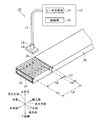
図1は、レーザ光を用いた絶縁皮膜剥離システム10の構成図である。以下では、特に断らない限り、レーザ光を用いた絶縁皮膜剥離システム10を、絶縁皮膜剥離システム10と呼ぶ。絶縁皮膜剥離システム10は、制御装置12を備える。制御装置12は、レーザ光源部14と、絶縁皮膜剥離方法に用いられる絶縁皮膜剥離プログラムを実行する制御部16を有する。絶縁皮膜剥離プログラムは、制御部16のメモリに格納される。レーザ光源部14は、波長1.06μmを有するYAGレーザと、YAGレーザが放射するレーザ光をビーム状に整形する光学系等を含む。レーザファイバ17は、レーザ光源部14から供給されるレーザ光20をレーザヘッド18に導く光学部品である。レーザヘッド18は、走査部19を備え、制御部16の制御の下で、照射対象物の任意の位置にレーザ光20を走査する。
FIG. 1 is a configuration diagram of an insulating
レーザ光源部14は、YAGレーザが放射し所定のレーザ出力W0を有するレーザ光を所定のビーム径d0のレーザビームに整形して出力する。レーザヘッド18から放射されるレーザ光20は、レーザ光源部14からのビーム径d0のレーザビームを、制御部16の制御の下で所定のパルス周波数f0でパルス化して放射されるパルスレーザ光である。
The laser light source unit 14 shapes the laser beam emitted by the YAG laser and has a predetermined laser output W0 into a laser beam having a predetermined beam diameter d0 and outputs the laser beam. The
走査部19は、レーザヘッド18に備えられ、レーザヘッド18の先端から放射されるビーム径d0のレーザビームを任意の方向に移動させる機構である。走査部19の機構としては、XYステージが用いられる。この場合は、XYステージのXY平面に対し平行に照射対象物の表面を配置し、XY平面に対し垂直下方にレーザビームを放射することで、照射対象物の表面にビーム径d0と同じ直径のスポット22が照射される。そこで、所定の走査経路24(図2参照)に沿ってXYステージを所定の走査速度V0(cm/s)で移動させることで、スポット22は、照射ピッチP0=(V0/f0)で走査経路24に沿って走査される。
The
以下では、レーザ光20は、波長が1.06μmでレーザ出力W0を有し、パルス周波数f0のパルスレーザ光が、照射対象物の表面にビーム径d0と同じ直径のスポット22として照射され、走査経路24に沿って、照射ピッチP0で走査されるものとする。
In the following, the
図1に、絶縁皮膜剥離システム10の構成要素ではないが、レーザ光20の照射対象物である絶縁皮膜付導線30を示す。絶縁皮膜付導線30は、車両に搭載される回転電機のステータ巻線に用いられるセグメントコイルである。絶縁皮膜付導線30は、断面形状が略矩形の導線32と、導線32の表面を被覆する絶縁皮膜34とを有する平角線である。導線32は、金属芯線で、銅線が用いられる。銅線に代えて、銅錫合金線、銀メッキ銅錫合金線等でもよい。絶縁皮膜34としては、ポリアミドイミドのエナメル皮膜が用いられる。
FIG. 1 shows a
セグメントコイルは、回転電機のステータコアに所定の配置関係で配置され、その先端部側は、他のセグメントコイルの先端部側と溶接等で結合され、所定の巻回方法で巻回された各相巻線を形成する。したがって、先端部側の絶縁皮膜を所定の剥離長さL0で剥離して導線32を露出させる必要があり、そのために、絶縁皮膜剥離システム10が用いられる。
The segment coils are arranged on the stator core of the rotary electric machine in a predetermined arrangement relationship, and the tip end side thereof is coupled to the tip end side of another segment coil by welding or the like, and each phase wound by a predetermined winding method. Form a winding. Therefore, it is necessary to peel off the insulating film on the tip end side with a predetermined peeling length L0 to expose the
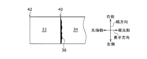
図1には、絶縁皮膜付導線30について、絶縁皮膜34がレーザ光20の照射によって剥離される剥離境界40を示す。絶縁皮膜付導線30の先端部42から測って剥離境界40までの長さが剥離長さL0である。剥離長さL0に対応する領域は、レーザ走査パターンが異なる2つの領域に分けられる。2つの領域の境界を領域境界44と呼ぶと、領域境界44は、先端部42から測って剥離境界40の手前に設定される。先端部42から領域境界44までの領域を第一領域50と呼び、領域境界44から剥離境界40までの領域を第二領域52と呼ぶ。第一領域の長手方向の長さと第二領域の長手方向の長さの関係は、(第一領域の長手方向の長さ)>(第二領域の長手方向の長さ)である。第一領域50と第二領域52とに分ける理由を含め、第一領域50と第二領域52の詳細については後述する。
FIG. 1 shows a peeling
図1に、互いに直交する三方向として、長手方向、幅方向、厚さ方向を示す。長手方向は、絶縁皮膜付導線30が延びる方向であり、長手方向の両方向を区別する場合には、絶縁皮膜付導線30の先端部42に向かう方向を先端側とし、反対方向を根元側とする。幅方向は、絶縁皮膜付導線30の幅方向であり、幅方向の両側を区別する場合には、根元側から先端側を見て右方向を右側とし、左方向を左側とする。厚さ方向は、絶縁皮膜付導線30の厚さ方向であり、厚さ方向の両側を区別する場合には、レーザ光20が照射される照射面の方向を上面側とし、反対側を下面側とする。以下の図でも同様である。
FIG. 1 shows the longitudinal direction, the width direction, and the thickness direction as three directions orthogonal to each other. The longitudinal direction is the direction in which the
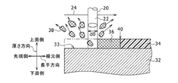
図2と図3は、波長1.06μmのレーザ光20による絶縁皮膜34の剥離を示す図である。各図において、レーザ光20のスポット22とその走査経路24とを示す。
2 and 3 are views showing peeling of the insulating
図2は、第一段階として、レーザ光20の照射によって絶縁皮膜34が炭化することを示す図である。波長1.06μmは、赤外線波長であるので、絶縁皮膜34の材質であるポリアミドイミドを透過し、導線32の銅を加熱する。レーザ光20の照射によって単位時間当たり単位面積の照射対象物が受けるエネルギをレーザエネルギ密度として、レーザエネルギ密度が所定以上あると、高温化した銅によってポリアミドイミドは炭化し、絶縁皮膜34は炭化層36となる。図2では、レーザ光20が走査経路24の先端側から根元側に向かって走査する途中を示すので、レーザ光20の現在のスポット22の位置よりも先端側の絶縁皮膜34が炭化層36となっている。
FIG. 2 is a diagram showing that the insulating
図3は、第一段階の後の第二段階として、炭化層36にレーザ光20が照射されると、黒色の炭化層36はレーザ光20のエネルギを吸収し高温となり、レーザエネルギ密度が所定以上あると、破片38となり気化して蒸散することを示す図である。図3では、レーザ光20が走査経路24に沿って先端側から根元側に向かって走査する途中を示すので、レーザ光20の現在のスポット22の位置よりも先端側の炭化層36が蒸散し、導線32の導線露出面33が現れている。このようにして、所定以上のレーザエネルギ密度のレーザ光20の照射によって、絶縁皮膜34が剥離される。
FIG. 3 shows that when the carbonized
図4は、絶縁皮膜剥離方法の手順を示すフローチャートである。各手順は、絶縁皮膜剥離システム10の制御部16によって実行される絶縁皮膜剥離プログラムの各処理手順に対応する。
FIG. 4 is a flowchart showing the procedure of the insulating film peeling method. Each procedure corresponds to each processing procedure of the insulating film peeling program executed by the
初めに剥離長さL0が設定される(S10)。剥離長さL0は、複数の絶縁皮膜付導線30の先端の導線露出面33を結合する結合装置の仕様等で定めることができる。結合装置の例は、溶接装置である。一例を挙げると、剥離長さL0は、数mmである。これは説明のための例示であって、場合によって10mmを超える場合もある。
First, the peeling length L0 is set (S10). The peeling length L0 can be determined by the specifications of a coupling device that couples the exposed
次に、剥離長さL0の部分について、第一領域50と第二領域52とが設定される(S12)。具体的には、長手方向に沿って、剥離長さL0を先端側のL50と根元側のL52の2つに分ける。ここで、L0=(L50+L52)で、L50>L52である。図1の例では、L50はL52の約5倍である。これは説明のための例示であって、結合装置の仕様、絶縁皮膜付導線30の仕様等によって適宜変更が可能である。
Next, the
そして、第一領域50について、折返し走査が行われる(S14)。折返し走査とは、走査領域内の一方側から他方側に向かってレーザヘッド18を移動させてレーザ光20の照射位置を移動する走査を行い、他方側に達した後、他方側から一方側に向かって、レーザ光の照射を継続しながらレーザヘッド18を移動させレーザ光20の照射位置を移動させて折り返す走査方法である。折返し数は、絶縁皮膜付導線30に対する絶縁皮膜剥離に必要な所定のレーザエネルギ密度の仕様等によって定められる。第一領域50の全体について折返し走査を行う走査モードを、以下では、レーザ光20の第一走査モードと呼ぶ。
Then, the folding scan is performed on the first region 50 (S14). Fold-back scanning is scanning in which the
また、第二領域52について、一方向走査が行われる(S16)。一方向走査とは、走査領域内の一方側から他方側に向かってレーザヘッド18を移動させてレーザ光20を照射する走査を行い、他方側に達したら、レーザ光20の照射を止めた状態でレーザヘッド18を移動させて一方側に戻らせる走査方法である。一方向走査の繰り返し数は、絶縁皮膜付導線30に対する絶縁皮膜剥離に必要な所定のレーザエネルギ密度の仕様、及び、絶縁皮膜付導線30の絶縁性能仕様等によって定められる。第二領域52の全体について一方向走査を行う走査モードを、以下では、レーザ光20の第二走査モードと呼ぶ。
Further, one-way scanning is performed on the second region 52 (S16). One-way scanning is a state in which the
S14とS16の処理順序は、S14を先に行い、次にS16を行う。これに代えて、S16を先に行い、次にS14を行ってもよい。 As for the processing order of S14 and S16, S14 is performed first, and then S16 is performed. Instead of this, S16 may be performed first, and then S14 may be performed.
剥離長さL0について第一領域50と第二領域52とに分けたのは、剥離境界40よりも根元側でレーザ光20の照射を受けない絶縁皮膜34の絶縁性能の確保と、絶縁皮膜付導線30の先端部42側における絶縁皮膜剥離の作業時間を短縮するためである。そこで、図5、図6を用いて、第一走査モードと第二走査モードについて述べる。図5は、第一領域50におけるレーザ光20の第一走査モード60を示す図であり、図6は、第二領域52におけるレーザ光20の第二走査モード62を示す図である。
The peeling length L0 was divided into the
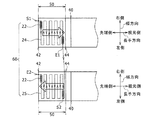
図5は、折返し走査を実行する第一走査モード60について、1回の折返し走査の走査経路24を示す図である。図5の上段の図は、1回の折返し走査の往路の走査経路24を示し、下段の図は、復路の走査経路25を示す。
FIG. 5 is a diagram showing a
図5における折返し走査の往路の走査経路24は以下の通りである。第一領域50の最も先端側で且つ最も右側の位置が、往路の走査開始位置S1である。レーザ光20は、パルスレーザ光であるので、レーザビームのスポット22は、照射ピッチP0で走査経路24上を走査する。右側を幅方向の一方側とすると、走査開始位置S1から幅方向における他方側である左側に向かう走査経路24に沿って、スポット22は幅方向に走査する。スポット22が幅方向の他方側である左側に達すると、スポット22は、長手方向に沿って長手方向の他方側である根元側に照射ピッチP0だけ微小走査する(図13参照)。長手方向の微小走査がなされた位置で、今度は、幅方向に沿って一方側である右側に向かう走査経路24に沿って、スポット22は幅方向に走査する。スポット22が幅方向の一方側である右側に達すると、スポット22は、長手方向に沿って長手方向の他方側である根元側に照射ピッチP0だけ微小走査し、次に、幅方向の他方側である左側へ向かう走査経路24に沿って走査する。なお、微小走査の前後において、適当な曲率半径を有してもよい。例えば、緩やかに照射ピッチを変更しながら走査方向を幅方向の他方側から幅方向の一方側に変化するようにしてもよい。以下で述べる「微小走査」についても同様である。
The
これを繰り返し、スポット22が第一領域50の最も根元側で且つ最も左側に達すると、そこが往路の走査終了位置E1である。図5の上段の図における白抜矢印は、幅方向の折返し走査を繰り返して、長手方向について先端側から根元側に向かって走査する第一走査モード60の往路部分を模式的に示す。
This is repeated, and when the
折返し走査の復路の走査経路25は、往路の走査終了位置E1を復路の走査開始位置S2とし、往路の走査経路24における走査方向を逆向きにした走査経路である。図5の下段の図では、第一領域50の最も先端側で且つ最も右側の位置が、復路の走査終了位置E2である。復路の走査終了位置E2は、往路の走査開始位置S1と同じである。図5の下段における白抜矢印は、幅方向の折返し走査を繰り返して、長手方向について根元側から先端側に向かって走査する第一走査モード60の復路部分を模式的に示す。
The
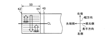
図6は、一方向走査を実行する第二走査モード62について、1回の一方向走査の走査経路26を示す図である。図6における一方向走査の1回の走査経路26は以下の通りである。第二領域52の最も先端側の領域境界44で且つ最も右側の位置が、一方向走査の走査経路26の走査開始位置S3である。先端側である領域境界44を長手方向の一方側とすると、走査開始位置S3から長手方向における他方側である剥離境界40に向かう走査経路26に沿って、スポット22は長手方向に走査する。スポット22が長手方向の他方側である剥離境界40に達すると、レーザ光20の照射を止めて、レーザヘッド18は、長手方向の一方側である領域境界44に戻り、さらに幅方向の他方側である左側に照射ピッチP0だけ微小移動する。その位置でレーザ光20の照射を始め、長手方向の他方側である剥離境界40に向かう走査経路26に沿って、スポット22の走査が行われる。スポット22が長手方向の他方側である剥離境界40に達すると、レーザ光20の照射を止めて、レーザヘッド18は、長手方向の一方側である領域境界44に戻り、さらに幅方向の他方側である左側に照射ピッチP0だけ微小移動する。これを繰り返して、スポット22が第二領域52の最も根元側の剥離境界40で且つ最も左側に達すると、そこが一方向走査の走査終了位置E3である。図6における白抜矢印は、長手方向の一方向走査を繰り返して、幅方向について右側から左側に向かって走査する第二走査モード62の1回分の走査を模式的に示す。
FIG. 6 is a diagram showing a
折返し走査と一方向走査の作用効果について、図7A、図7B、図8A、図8Bを用いて説明する。図7Aと図8Aは、それぞれ図5、図6の白抜矢印の走査方向を抜き出して示し、t0,t1等は、走査時間である。走査開始時間がt0で、時間経過と共にtの後の数字が増加する。四角枠で囲んだA,B,Cは、領域内の温度評価位置である。図7Bと図8Bは、横軸に時間、縦軸に温度を取り、対応する図7Aと図8Aの温度評価位置における温度の時間変化を示す図である。 The effects of the folded scan and the one-way scan will be described with reference to FIGS. 7A, 7B, 8A, and 8B. 7A and 8A show the scanning directions of the white arrows in FIGS. 5 and 6, respectively, and t0, t1, etc. are scanning times. The scanning start time is t0, and the number after t increases with the passage of time. A, B, and C surrounded by a square frame are temperature evaluation positions in the region. 7B and 8B are diagrams showing time changes in temperature at the corresponding temperature evaluation positions of FIGS. 7A and 8A, with time on the horizontal axis and temperature on the vertical axis.
図7Bは、折返し走査について、第一領域50内の温度評価位置として、先端側にA点、根元側の領域境界44付近にB点を取り、それぞれについて温度の時間変化を示す図である。A点もB点もレーザヘッド18の1往復につき、2回の照射を受けるが、B点は、折返し走査におけるレーザヘッド18の折返し点であり、時間t2でレーザヘッド18の往路のスポット22の照射を受け、引き続き時間t3で復路のスポット22の照射を受ける。{(時間t3)−(時間t2)}は、スポット22の照射ピッチP0の移動時間で、(照射ピッチP0/走査速度V0)で計算され、短い時間である。すなわち、折返し位置であるB点においては、短い時間内で2回の照射を受けるので、往路のスポット22の照射による熱が放熱されないうちに復路のスポット22の照射の熱を受ける。これにより、折返し位置であるB点の温度T2は、他の位置の温度よりも高くなり、絶縁皮膜付導線30における絶縁皮膜34の剥離効率が他の位置に比べ向上する。図5で述べたように、第一領域50における1回の折返し走査では、第一領域50の右側の側縁全体、左側の側縁全体、領域境界44の全体に連続して折返し位置が生じる。これらの折返し位置において、絶縁皮膜34の剥離効率が向上するので、一方向走査が行われる場合に比較して、第一領域50における絶縁皮膜剥離の作業時間が短縮される。
FIG. 7B is a diagram showing the time change of the temperature for each of the folded scans, with the point A on the tip side and the point B near the
一方、折返し点から離れたA点では、時間t1で往路のスポット22の照射を受け、1往復後の時間t4で復路のスポット22の照射を受けるので、照射間隔が長く、A点の温度T1は、B点の温度T2に比べ低い温度となる。照射間隔が十分長い場合には、A点の温度T1は、一方向走査が行われた場合の温度と同じとなる。
On the other hand, at point A away from the turning point, the
図8Bは、一方向走査について、第二領域52内の温度評価位置として、剥離境界40付近にC点を取り、2つの走査経路26に沿ってそれぞれ一方向走査を行った場合の温度の時間変化を示す図である。一方向走査においてレーザヘッド18は、領域境界44から剥離境界40に移動する時にレーザ光20を照射するが、剥離境界40から領域境界44に戻る時はレーザ光20の照射を止める。図8Bの例では、C点は、時間t1においてレーザ光20の照射を受けて温度がT1に上がるが、t2で温度が下がり始め、次にレーザ光20の照射を受ける時間t3で再び温度がT1に上昇する。第二領域52内では、どの位置においても、一定の時間間隔をおいてスポット22の照射を受け、図7Bの折返し走査におけるB点のように、他に比べて短い時間間隔でレーザ光20の照射を受ける位置がない。第二領域52内では、どの位置においてもレーザ光20の照射を受けた時間に温度がT1に上がるが、それ以上の温度になることがない。
FIG. 8B shows the temperature time when one-way scanning is performed along the two
図7B、図8Bを比較して分かるように、折返し走査においては、折返し位置が高い温度T2となるが、一方向走査においては、どの位置もT2より低い温度T1である。また、折返し走査では、レーザヘッド18の一往復の全体においてスポット22の照射を受けるが、一方向走査では、レーザヘッド18の一往復のうち、半分の往路のみにおいてスポット22の照射を受ける。このことにより、折返し走査が行われる第一領域50においては絶縁皮膜34の剥離効率が向上し、1往復の全部の時間に渡ってスポット22の照射を受けるので、絶縁皮膜剥離の作業時間が短縮される。一方向走査が行われる第二領域52では、絶縁皮膜剥離のための走査時間が長くなるが、剥離境界40よりも根元側の絶縁皮膜34は過度の高温に曝されることがないので、絶縁性能が確保される。
As can be seen by comparing FIGS. 7B and 8B, in the folding scan, the folding position has a high temperature T2, but in the one-way scanning, all the positions have a temperature T1 lower than T2. Further, in the folded scan, the
図7A、図7BのA点は、折返し走査において、折返し位置から離れた位置であるので、スポット22の照射を受ける時間間隔が長く、温度は一方向走査のC点と同じT1である。このことから、レーザ光20の照射を受ける時間間隔を短時間になるようにすれば、その位置の温度を高くできることになる。
Since the point A in FIGS. 7A and 7B is a position away from the folding position in the folding scan, the time interval for receiving the irradiation of the
図9Aと図9Bは、第一領域50において、折返し走査の照射開始位置を先端部42と領域境界44の中間位置CLに設定し、図7と同じ先端側のA点と根元側のB点の温度の時間変化を示す図である。図9Aは図7Aに対応する図であり、図9Bは図7Bに対応する図である。
In FIGS. 9A and 9B, in the
図9Aに示すように、中間位置CLにおける時間t0で照射が開始し、先端側に向かって走査され、時間t1で先端部42に達し、そこで折り返し、時間t2から根元側に向かって走査し時間t3で中間位置CLを通過して時間t4で根元側に達する。そこで折り返し、時間t5から中間位置CLに向かって走査され、時間t6で中間位置CLに戻る。この場合、A点もB点も折返し位置となるので、図9Bに示すように、高い温度T2となる。
As shown in FIG. 9A, irradiation starts at time t0 at the intermediate position CL, is scanned toward the tip side, reaches the
図10A、図10B、図10Cは、折返し走査の他の例を示す図である。図9Aでは、スポット22の走査方向として、幅方向の折返し走査を繰り返しながら、長手方向に走査し、長手方向の折返し走査を行ったが、その順序を逆にしてもよい。図10Aは、スポット22の走査方向として、長手方向の折返し走査を繰り返しながら、幅方向に走査することで、幅方向の折返し走査を行う場合を示す。この場合の中間位置CLは、第一領域50における幅方向の中間の位置となる。図10Bは、第一領域50を3つのサブ領域54に分け、それぞれに中間位置CLを設ける例である。この場合、高い温度T2を有する折返し位置を、合計6つに増やすことができる。図10Cは、第一領域50を6つのサブ領域56に分け、それぞれに中間位置CLを設ける例である。この場合、高い温度T2を有する折返し位置を、合計12に増やすことができる。このように、第一領域50を複数のサブ領域54,56に分けて、それぞれについて中間位置CLを照射開始位置として折返し走査を行うことで、高い温度T2を有する折返し位置の数を増やすことができる。
10A, 10B, and 10C are diagrams showing other examples of the folded scan. In FIG. 9A, as the scanning direction of the
上記では、第二領域52における一方向走査のスポット22の走査方向として、領域境界44から剥離境界40に向かう長手方向の一方向走査を繰り返すものとした。図11A、図11B、11Cは、一方向走査の走査方向の例を示す図である。図11Aは、スポット22の走査方向を長手方向に対し所定の角度θで傾斜する。図11Bは図11Aとは反対方向に所定の角度θで傾斜する例である。スポット22の走査方向を長手方向に傾斜させることで、傾斜していない場合に比較して、走査時間が長くなり、ゆっくりと絶縁皮膜34の剥離処理ができ、剥離境界40よりも根元側の絶縁性能の確保が容易になる。図11Cは、傾斜した角度θを付けないが、スポット22の走査方向として、剥離境界40から領域境界44に向かう長手方向の一方向走査を繰り返す例を示す図である。一方向走査においては、どの位置も同じ温度T1であるので、図11Cの場合も剥離境界40は温度T1となり、剥離境界40よりも根元側の絶縁皮膜34の絶縁性能を確保できる。
In the above, as the scanning direction of the
上記構成の作用効果について、比較例を用いてさらに説明する。図12は、第二領域52を設けない場合について、剥離境界40付近の絶縁皮膜34の状態を示す図である。この場合、剥離境界40よりも根元側にはレーザ光20が照射されないが、剥離境界40よりも先端側には絶縁皮膜剥離の作業時間の短縮のために折返し走査が行われる。したがって、剥離境界40は、高い温度T2となり、絶縁機能のために本来残しておきたい絶縁皮膜34の部分まで過度に加熱され、図12に示すように、炭化層36が生じることがある。剥離境界40よりも根元側の絶縁皮膜34の部分に炭化層36が生じると、剥離長さL0がばらつき、絶縁性能が低下する恐れがある。これに対し、図4の絶縁皮膜剥離方法においては、一方向走査が行われる第二領域52が設けられるので、剥離境界40の温度はT1よりも低い温度T2となり、剥離境界40付近に炭化層36が生じることが抑制され、剥離長さL0がばらつかない。
The effects of the above configuration will be further described with reference to comparative examples. FIG. 12 is a diagram showing a state of the insulating
次に、従来技術において、絶縁皮膜剥離の作業時間を短縮するために用いられる方法と比較する。レーザ光20を用いて絶縁皮膜34を剥離するには、単位時間、単位面積当たりに一定値以上の熱エネルギを付与する必要がある。そのためには、パルス周波数が一定の場合には、走査速度を遅くして、照射ピッチを狭くすることになる。図13Aは、照射ピッチP0の例で、図13Bは図13Aよりも狭い照射ピッチP1の例である。図13A と図13Bを比較して分かるように、照射ピッチを狭くすると、単位時間に走査経路24を走査する長さである走査速度が遅くなる。したがって、絶縁皮膜剥離の作業時間が長くなる。これに対し、図4の絶縁皮膜剥離方法では、第一領域50の絶縁皮膜剥離の作業時間を短縮できるが、照射ピッチは常にP0の一定値で、特に狭くする必要がない。
Next, it is compared with the method used in the prior art for shortening the working time of peeling the insulating film. In order to peel off the insulating
従来技術において、照射ピッチが一定の場合に絶縁皮膜剥離の作業時間を短縮するには、レーザ出力を高くするか、パルス周波数を高くするかである。レーザ出力を高くするには、大出力のレーザ光源部14とする必要があり、装置コストが高くなる。これに対し、図4の絶縁皮膜剥離方法では、第一領域50の絶縁皮膜剥離の作業時間を短縮できるが、レーザ光源部14のレーザ出力は常にW0の一定値で、特に大出力にする必要がない。
In the prior art, in order to shorten the working time of insulating film peeling when the irradiation pitch is constant, the laser output is increased or the pulse frequency is increased. In order to increase the laser output, it is necessary to use a high-power laser light source unit 14, which increases the equipment cost. On the other hand, in the method of peeling the insulating film of FIG. 4, the working time of peeling the insulating film in the
従来技術において、照射ピッチが一定でレーザ出力が一定の場合に絶縁皮膜剥離の作業時間を短縮するにはパルス周波数を高くする。図14Aと図14Bは、レーザ光20のパルス周波数を高くする場合を示す図である。図14Aは、パルス周波数f0の場合について、連続して放射される3つのスポット22を並べて、その位置精度を示す図である。f0は、各スポット22の位置精度が所定の範囲を超えてばらつかないように設定されている。図14Bは、f0より高いパルス周波数f1について、連続して放射される3つのスポット22を並べて、その位置精度を示す図である。パルス周波数をf0からf1に上げると、N回目のスポット22の照射から次の(N+1)回目のスポット22の照射へ移る時間が短くなり、スポット22の走査経路24上の位置精度が低下する。図14Bでは、スポット22の位置精度のばらつきを破線で示す。これに対し、図4の絶縁皮膜剥離方法では、第一領域50の絶縁皮膜剥離の作業時間を短縮できるが、パルス周波数は常にf0の一定値で、特に上げる必要がない。
In the prior art, when the irradiation pitch is constant and the laser output is constant, the pulse frequency is increased in order to shorten the working time for peeling the insulating film. 14A and 14B are diagrams showing a case where the pulse frequency of the
上記のように、図4の絶縁皮膜剥離方法では、レーザ光20に関するレーザ出力、照射ピッチ、パルス周波数を特に変更することなく、絶縁皮膜付導線30の先端側に折返し走査を行う第一領域50を設けて、絶縁皮膜剥離の作業時間を短縮できる。また、第一領域50と剥離境界40との間に一方向走査を行う第二領域52を設けて、絶縁皮膜付導線30の絶縁性能を確保することができる。
As described above, in the insulating film peeling method of FIG. 4, the
10 (レーザ光を用いた)絶縁皮膜剥離システム、12 制御装置、14 レーザ光源部、16 制御部、17 レーザファイバ、18 レーザヘッド、19 走査部、20 レーザ光、22 スポット、24,25,26 走査経路、30 絶縁皮膜付導線、32 導線、33 導線露出面、34 絶縁皮膜、36 炭化層、38 破片、40 剥離境界、42 先端部、44 領域境界、50 第一領域、52 第二領域、54,56 サブ領域、60 第一走査モード、62 第二走査モード。 10 Insulation film peeling system (using laser light), 12 control device, 14 laser light source part, 16 control part, 17 laser fiber, 18 laser head, 19 scanning part, 20 laser light, 22 spots, 24, 25, 26 Scanning path, 30 Insulated lead wire, 32 lead wire, 33 lead wire exposed surface, 34 insulating film, 36 carbonized layer, 38 debris, 40 peeling boundary, 42 tip, 44 region boundary, 50 first region, 52 second region, 54, 56 sub-regions, 60 first scan mode, 62 second scan mode.
Claims (7)
前記先端部から測って前記剥離境界の手前に予め定めた領域境界までの第一領域について、一方側から他方側に向かって前記レーザ光の照射位置を移動し、前記他方側に達した後、前記他方側から前記一方側に向かって前記レーザ光の照射位置を移動する折返し走査を行う第一領域走査工程と、
前記領域境界から前記剥離境界までの第二領域について、一方側から他方側に向かって前記レーザ光の照射を行い、前記他方側に達したら、前記レーザ光の照射を止めた状態で前記一方側に戻る一方向走査を行う第二領域走査工程と、
を含む、絶縁皮膜剥離方法。 A portion of a conductor with an insulating film having a conducting wire and an insulating film covering the conducting wire, which is irradiated with laser light in the longitudinal direction and measured from the tip portion to a peeling boundary having a predetermined peeling length. This is an insulating film peeling method for peeling the insulating film.
After moving the irradiation position of the laser beam from one side to the other side with respect to the first region measured from the tip portion to the region boundary predetermined in front of the peeling boundary and reaching the other side. A first region scanning step of performing a turn-back scanning that moves the irradiation position of the laser beam from the other side to the one side.
The laser beam is irradiated from one side to the other side of the second region from the region boundary to the peeling boundary, and when the other side is reached, the laser beam irradiation is stopped and the one side is stopped. The second region scanning step of performing one-way scanning and
Insulation film peeling method including.
前記先端部から測って前記剥離境界の手前に予め定めた領域境界までの第一領域について、中間位置から他方側に向かって前記レーザ光の照射位置を移動し、前記他方側に達した後、前記他方側から前記一方側に向かって前記レーザ光の照射位置を移動して折り返し、前記一方側に達した後、前記一方側から前記中間位置に向かって前記レーザ光の照射位置を移動して折り返し前記中間位置に戻る折返し走査を行う第一領域走査工程と、
前記領域境界から前記剥離境界までの第二領域について、一方側から他方側に向かって前記レーザ光の照射を行い、前記他方側に達したら、前記レーザ光の照射を止めた状態で前記一方側に戻る一方向走査を行う第二領域走査工程と、
を含む、絶縁皮膜剥離方法。 A portion of a conductor with an insulating film having a conducting wire and an insulating film covering the conducting wire, which is irradiated with laser light in the longitudinal direction and measured from the tip portion to a peeling boundary having a predetermined peeling length. This is an insulating film peeling method for peeling the insulating film.
After moving the irradiation position of the laser beam from the intermediate position toward the other side and reaching the other side with respect to the first region measured from the tip portion to the region boundary predetermined in front of the peeling boundary. The laser beam irradiation position is moved from the other side toward the one side and folded back, and after reaching the one side, the laser light irradiation position is moved from the one side toward the intermediate position. Folding The first region scanning step of performing folding scanning to return to the intermediate position, and
The laser beam is irradiated from one side to the other side of the second region from the region boundary to the peeling boundary, and when the other side is reached, the laser beam irradiation is stopped and the one side is stopped. The second region scanning step of performing one-way scanning and
Insulation film peeling method including.
前記一方側は、前記先端部であり、前記他方側は、前記領域境界であり、
前記第二領域走査工程において、
前記一方側は、前記領域境界であり、前記他方側は、前記剥離境界である、請求項1または請求項2に記載の絶縁皮膜剥離方法。 In the first region scanning step,
The one side is the tip portion, and the other side is the region boundary.
In the second region scanning step,
The method for peeling an insulating film according to claim 1 or 2, wherein one side is the region boundary and the other side is the peeling boundary.
前記第一領域走査工程においては、
前記長手方向の前記一方側を前記先端部とし、前記長手方向の前記他方側を前記領域境界として、
前記レーザ光の移動は、
前記右側と前記左側との間で照射ピッチ毎の微小移動による微小走査による幅方向の折返し走査を行い、
前記先端部から前記領域境界へ向かって前記幅方向の折返し走査を繰り返して長手方向について前記先端部から前記領域境界に向かう往路走査を行い、往路走査の後、前記領域境界から前記先端部へ向かって前記幅方向の折返し走査を繰り返して前記長手方向について前記領域境界から前記先端部に向かう復路走査を行い、これを所定回数繰り返して第一領域走査における折返し走査とし、
前記第二領域走査工程においては、
前記長手方向の前記一方側を前記領域境界とし、前記長手方向の前記他方側を前記剥離境界として、
前記レーザ光の移動は、
前記領域境界から前記剥離境界へ向かって照射ピッチ毎の微小移動による微小走査による長手方向の一方向折返し走査を行い、
前記幅方向の右側から前記幅方向の左側へ向かって前記長手方向の一方向折返し走査を行い、これを所定回数繰り返して第二領域走査における一方向走査とする、請求項1または請求項2に記載の絶縁皮膜剥離方法。 The direction in which the conducting wire with the insulating film extends is the longitudinal direction, the right side along the width of the conducting wire with the insulating coating is the right side in the width direction, and the left side is the left side in the width direction.
In the first region scanning step,
The one side in the longitudinal direction is the tip portion, and the other side in the longitudinal direction is the region boundary.
The movement of the laser beam is
Fold-back scanning in the width direction is performed by minute scanning by minute movement for each irradiation pitch between the right side and the left side.
The folding scan in the width direction is repeated from the tip portion toward the region boundary to perform an outward scan from the tip portion to the region boundary in the longitudinal direction, and after the outward scan, the region boundary is directed toward the tip portion. The folding scan in the width direction is repeated to perform a return scan from the region boundary to the tip portion in the longitudinal direction, and this is repeated a predetermined number of times to obtain a folding scan in the first region scanning.
In the second region scanning step,
The one side in the longitudinal direction is used as the region boundary, and the other side in the longitudinal direction is used as the peeling boundary.
The movement of the laser beam is
One-way folding scanning in the longitudinal direction is performed by minute scanning by minute movement at each irradiation pitch from the region boundary to the peeling boundary.
2. The method for peeling an insulating film.
前記第一領域を複数のサブ領域に分け、
各前記サブ領域について、前記サブ領域の中間位置を照射開始位置とする、請求項2に記載の絶縁皮膜剥離方法。 The first region scanning step is
The first region is divided into a plurality of sub-regions.
The method for peeling an insulating film according to claim 2, wherein an intermediate position of the sub-region is set as an irradiation start position for each of the sub-regions.
前記レーザ光の移動は、
前記絶縁皮膜付導線の長手方向に対し所定の角度で傾斜した走査方向に沿った照射ピッチ毎の微小移動である、請求項1または2に記載の絶縁皮膜剥離方法。 In the second region scanning step,
The movement of the laser beam is
The method for peeling an insulating film according to claim 1 or 2, wherein it is a minute movement for each irradiation pitch along a scanning direction inclined at a predetermined angle with respect to the longitudinal direction of the conducting wire with an insulating film.
Priority Applications (3)
| Application Number | Priority Date | Filing Date | Title |
|---|---|---|---|
| JP2018041006A JP6947664B2 (en) | 2018-03-07 | 2018-03-07 | Insulation film peeling method |
| US16/286,794 US11251591B2 (en) | 2018-03-07 | 2019-02-27 | Insulation film peeling method |
| CN201910159903.7A CN110238529B (en) | 2018-03-07 | 2019-03-04 | Method for peeling insulating film |
Applications Claiming Priority (1)
| Application Number | Priority Date | Filing Date | Title |
|---|---|---|---|
| JP2018041006A JP6947664B2 (en) | 2018-03-07 | 2018-03-07 | Insulation film peeling method |
Publications (2)
| Publication Number | Publication Date |
|---|---|
| JP2019155375A JP2019155375A (en) | 2019-09-19 |
| JP6947664B2 true JP6947664B2 (en) | 2021-10-13 |
Family
ID=67842157
Family Applications (1)
| Application Number | Title | Priority Date | Filing Date |
|---|---|---|---|
| JP2018041006A Active JP6947664B2 (en) | 2018-03-07 | 2018-03-07 | Insulation film peeling method |
Country Status (3)
| Country | Link |
|---|---|
| US (1) | US11251591B2 (en) |
| JP (1) | JP6947664B2 (en) |
| CN (1) | CN110238529B (en) |
Families Citing this family (6)
| Publication number | Priority date | Publication date | Assignee | Title |
|---|---|---|---|---|
| JP7432626B2 (en) * | 2020-01-31 | 2024-02-16 | 株式会社アイシン | How to remove the insulation coating of conductor wires |
| DE102020212087A1 (en) * | 2020-09-25 | 2022-03-31 | Trumpf Laser- Und Systemtechnik Gmbh | Multi-stage laser stripping of a rod-shaped conductor |
| WO2022186356A1 (en) * | 2021-03-03 | 2022-09-09 | 古河電気工業株式会社 | Film removal method and film removal device |
| WO2023175671A1 (en) * | 2022-03-14 | 2023-09-21 | 株式会社 東芝 | Laser removal method, method for manufacturing rotary electrical machine, and laser removal device |
| DE102022117276A1 (en) | 2022-07-12 | 2024-01-18 | Schaeffler Technologies AG & Co. KG | Method for producing a wave winding with stripped wire ends |
| WO2024053744A1 (en) * | 2022-09-08 | 2024-03-14 | 古河電気工業株式会社 | Film removal method and film removal device |
Family Cites Families (11)
| Publication number | Priority date | Publication date | Assignee | Title |
|---|---|---|---|---|
| JPH08182142A (en) * | 1994-12-26 | 1996-07-12 | Fujikura Ltd | Laser beam machining method |
| JP4275120B2 (en) | 2005-08-31 | 2009-06-10 | Tdk株式会社 | Coil parts manufacturing method and manufacturing apparatus |
| US20070193985A1 (en) * | 2006-02-20 | 2007-08-23 | Howard Patrick C | Method for removing a coating from a substrate using a defocused laser beam |
| JP2008109753A (en) * | 2006-10-24 | 2008-05-08 | Tdk Corp | Coating exfoliation method |
| JP2009297732A (en) | 2008-06-11 | 2009-12-24 | Aisin Aw Co Ltd | Method and apparatus of removing insulation coating film of insulation coated conductor |
| JP5394046B2 (en) * | 2008-11-26 | 2014-01-22 | 三桜工業株式会社 | Method for removing coated resin layer of resin-coated metal pipe |
| CN102896425A (en) * | 2012-09-26 | 2013-01-30 | 北京工业大学 | Method for rapidly preparing large area nano texture on metal surface by ultrafast laser |
| CN103692087B (en) * | 2013-12-03 | 2016-01-27 | 浙江温医雷赛医用激光科技有限公司 | The scan method that a kind of laser ablation based on space and time optimization is processed |
| JP2017123294A (en) | 2016-01-08 | 2017-07-13 | 株式会社オートネットワーク技術研究所 | Method of producing conductive member |
| JP6565798B2 (en) * | 2016-06-10 | 2019-08-28 | トヨタ自動車株式会社 | Film removal device |
| CN107175409A (en) * | 2017-05-26 | 2017-09-19 | 苏州菲镭泰克激光技术有限公司 | The three-dimensional laser fine machining system and method for crisp and hard material |
-
2018
- 2018-03-07 JP JP2018041006A patent/JP6947664B2/en active Active
-
2019
- 2019-02-27 US US16/286,794 patent/US11251591B2/en active Active
- 2019-03-04 CN CN201910159903.7A patent/CN110238529B/en active Active
Also Published As
| Publication number | Publication date |
|---|---|
| US20190280574A1 (en) | 2019-09-12 |
| JP2019155375A (en) | 2019-09-19 |
| CN110238529B (en) | 2021-05-04 |
| US11251591B2 (en) | 2022-02-15 |
| CN110238529A (en) | 2019-09-17 |
Similar Documents
| Publication | Publication Date | Title |
|---|---|---|
| JP6947664B2 (en) | Insulation film peeling method | |
| JP2683926B2 (en) | Insulation-coated wire stripping method and device | |
| KR101866601B1 (en) | Laser direct ablation with picosecond laser pulses at high pulse repetition frequencies | |
| JPH02297932A (en) | Manufacture of via holein copolymen induction layzy | |
| CN110340541B (en) | Wave-push type laser processing method, device and system | |
| JP2005136218A (en) | Method for activating impurity, and laser irradiation equipment | |
| US7632420B2 (en) | Laser removal of layer or coating from a substrate | |
| JP7063693B2 (en) | Flat wire laser welding method | |
| US20230219170A1 (en) | Multi-stage laser stripping of a rod-shaped conductor | |
| CN110957676B (en) | Method for removing coating layer of coil wire | |
| JP2013109948A (en) | Joining structure and joining method for rectangular wires | |
| JP2017037800A (en) | Cable harness and manufacturing method of the same | |
| KR20230049635A (en) | Laser Welding of Metal Pin Pairs with Time-Dependent Scan Pattern and Energy Input | |
| JP2010129970A (en) | Semiconductor device, and method of manufacturing semiconductor integrated circuit chip | |
| JP2010253492A (en) | Laser beam welding apparatus | |
| KR100894025B1 (en) | Method for resistor trimming with small uniform spot from solid-state UV laser | |
| JP5693074B2 (en) | Laser processing method | |
| CN1819878B (en) | Laser removal of layer or coating from a substrate | |
| JP2008109753A (en) | Coating exfoliation method | |
| JP4000187B2 (en) | Method of removing insulation coating from coil end | |
| JPH08182142A (en) | Laser beam machining method | |
| JP2009297732A (en) | Method and apparatus of removing insulation coating film of insulation coated conductor | |
| JP6519819B2 (en) | Method of manufacturing element chip | |
| US20220337136A1 (en) | Method for producing a stator arrangement | |
| JP6299438B2 (en) | Flat wire joining method |
Legal Events
| Date | Code | Title | Description |
|---|---|---|---|
| A621 | Written request for application examination |
Free format text: JAPANESE INTERMEDIATE CODE: A621 Effective date: 20201015 |
|
| A977 | Report on retrieval |
Free format text: JAPANESE INTERMEDIATE CODE: A971007 Effective date: 20210811 |
|
| TRDD | Decision of grant or rejection written | ||
| A01 | Written decision to grant a patent or to grant a registration (utility model) |
Free format text: JAPANESE INTERMEDIATE CODE: A01 Effective date: 20210824 |
|
| A61 | First payment of annual fees (during grant procedure) |
Free format text: JAPANESE INTERMEDIATE CODE: A61 Effective date: 20210916 |
|
| R151 | Written notification of patent or utility model registration |
Ref document number: 6947664 Country of ref document: JP Free format text: JAPANESE INTERMEDIATE CODE: R151 |