JP6941936B2 - Decelerator - Google Patents

Decelerator Download PDF

Info

Publication number
JP6941936B2
JP6941936B2 JP2016236080A JP2016236080A JP6941936B2 JP 6941936 B2 JP6941936 B2 JP 6941936B2 JP 2016236080 A JP2016236080 A JP 2016236080A JP 2016236080 A JP2016236080 A JP 2016236080A JP 6941936 B2 JP6941936 B2 JP 6941936B2
Authority
JP
Japan
Prior art keywords
intersection
gear
carrier member
casing
external
Prior art date
Legal status (The legal status is an assumption and is not a legal conclusion. Google has not performed a legal analysis and makes no representation as to the accuracy of the status listed.)
Active
Application number
JP2016236080A
Other languages
Japanese (ja)
Other versions
JP2018091427A (en
Inventor
安藤 学
学 安藤
真司 吉田
真司 吉田
Current Assignee (The listed assignees may be inaccurate. Google has not performed a legal analysis and makes no representation or warranty as to the accuracy of the list.)
Sumitomo Heavy Industries Ltd
Original Assignee
Sumitomo Heavy Industries Ltd
Priority date (The priority date is an assumption and is not a legal conclusion. Google has not performed a legal analysis and makes no representation as to the accuracy of the date listed.)
Filing date
Publication date
Application filed by Sumitomo Heavy Industries Ltd filed Critical Sumitomo Heavy Industries Ltd
Priority to JP2016236080A priority Critical patent/JP6941936B2/en
Priority to KR1020170155757A priority patent/KR102381750B1/en
Priority to DE102017128635.7A priority patent/DE102017128635A1/en
Priority to CN201711259815.1A priority patent/CN108150613B/en
Publication of JP2018091427A publication Critical patent/JP2018091427A/en
Application granted granted Critical
Publication of JP6941936B2 publication Critical patent/JP6941936B2/en
Active legal-status Critical Current
Anticipated expiration legal-status Critical

Links

Images

Classifications

    • FMECHANICAL ENGINEERING; LIGHTING; HEATING; WEAPONS; BLASTING
    • F16ENGINEERING ELEMENTS AND UNITS; GENERAL MEASURES FOR PRODUCING AND MAINTAINING EFFECTIVE FUNCTIONING OF MACHINES OR INSTALLATIONS; THERMAL INSULATION IN GENERAL
    • F16CSHAFTS; FLEXIBLE SHAFTS; ELEMENTS OR CRANKSHAFT MECHANISMS; ROTARY BODIES OTHER THAN GEARING ELEMENTS; BEARINGS
    • F16C19/00Bearings with rolling contact, for exclusively rotary movement
    • F16C19/22Bearings with rolling contact, for exclusively rotary movement with bearing rollers essentially of the same size in one or more circular rows, e.g. needle bearings
    • F16C19/34Bearings with rolling contact, for exclusively rotary movement with bearing rollers essentially of the same size in one or more circular rows, e.g. needle bearings for both radial and axial load
    • F16C19/36Bearings with rolling contact, for exclusively rotary movement with bearing rollers essentially of the same size in one or more circular rows, e.g. needle bearings for both radial and axial load with a single row of rollers
    • F16C19/364Bearings with rolling contact, for exclusively rotary movement with bearing rollers essentially of the same size in one or more circular rows, e.g. needle bearings for both radial and axial load with a single row of rollers with tapered rollers, i.e. rollers having essentially the shape of a truncated cone
    • FMECHANICAL ENGINEERING; LIGHTING; HEATING; WEAPONS; BLASTING
    • F16ENGINEERING ELEMENTS AND UNITS; GENERAL MEASURES FOR PRODUCING AND MAINTAINING EFFECTIVE FUNCTIONING OF MACHINES OR INSTALLATIONS; THERMAL INSULATION IN GENERAL
    • F16HGEARING
    • F16H57/00General details of gearing
    • F16H57/02Gearboxes; Mounting gearing therein
    • F16H57/021Shaft support structures, e.g. partition walls, bearing eyes, casing walls or covers with bearings
    • FMECHANICAL ENGINEERING; LIGHTING; HEATING; WEAPONS; BLASTING
    • F16ENGINEERING ELEMENTS AND UNITS; GENERAL MEASURES FOR PRODUCING AND MAINTAINING EFFECTIVE FUNCTIONING OF MACHINES OR INSTALLATIONS; THERMAL INSULATION IN GENERAL
    • F16HGEARING
    • F16H1/00Toothed gearings for conveying rotary motion
    • F16H1/28Toothed gearings for conveying rotary motion with gears having orbital motion
    • F16H1/32Toothed gearings for conveying rotary motion with gears having orbital motion in which the central axis of the gearing lies inside the periphery of an orbital gear
    • FMECHANICAL ENGINEERING; LIGHTING; HEATING; WEAPONS; BLASTING
    • F16ENGINEERING ELEMENTS AND UNITS; GENERAL MEASURES FOR PRODUCING AND MAINTAINING EFFECTIVE FUNCTIONING OF MACHINES OR INSTALLATIONS; THERMAL INSULATION IN GENERAL
    • F16HGEARING
    • F16H49/00Other gearings
    • F16H49/001Wave gearings, e.g. harmonic drive transmissions
    • FMECHANICAL ENGINEERING; LIGHTING; HEATING; WEAPONS; BLASTING
    • F16ENGINEERING ELEMENTS AND UNITS; GENERAL MEASURES FOR PRODUCING AND MAINTAINING EFFECTIVE FUNCTIONING OF MACHINES OR INSTALLATIONS; THERMAL INSULATION IN GENERAL
    • F16HGEARING
    • F16H57/00General details of gearing
    • F16H57/02Gearboxes; Mounting gearing therein
    • F16H57/023Mounting or installation of gears or shafts in the gearboxes, e.g. methods or means for assembly
    • FMECHANICAL ENGINEERING; LIGHTING; HEATING; WEAPONS; BLASTING
    • F16ENGINEERING ELEMENTS AND UNITS; GENERAL MEASURES FOR PRODUCING AND MAINTAINING EFFECTIVE FUNCTIONING OF MACHINES OR INSTALLATIONS; THERMAL INSULATION IN GENERAL
    • F16HGEARING
    • F16H57/00General details of gearing
    • F16H57/02Gearboxes; Mounting gearing therein
    • F16H57/029Gearboxes; Mounting gearing therein characterised by means for sealing the gearboxes, e.g. to improve airtightness
    • FMECHANICAL ENGINEERING; LIGHTING; HEATING; WEAPONS; BLASTING
    • F16ENGINEERING ELEMENTS AND UNITS; GENERAL MEASURES FOR PRODUCING AND MAINTAINING EFFECTIVE FUNCTIONING OF MACHINES OR INSTALLATIONS; THERMAL INSULATION IN GENERAL
    • F16HGEARING
    • F16H1/00Toothed gearings for conveying rotary motion
    • F16H1/28Toothed gearings for conveying rotary motion with gears having orbital motion
    • F16H1/32Toothed gearings for conveying rotary motion with gears having orbital motion in which the central axis of the gearing lies inside the periphery of an orbital gear
    • F16H2001/323Toothed gearings for conveying rotary motion with gears having orbital motion in which the central axis of the gearing lies inside the periphery of an orbital gear comprising eccentric crankshafts driving or driven by a gearing
    • FMECHANICAL ENGINEERING; LIGHTING; HEATING; WEAPONS; BLASTING
    • F16ENGINEERING ELEMENTS AND UNITS; GENERAL MEASURES FOR PRODUCING AND MAINTAINING EFFECTIVE FUNCTIONING OF MACHINES OR INSTALLATIONS; THERMAL INSULATION IN GENERAL
    • F16HGEARING
    • F16H57/00General details of gearing
    • F16H57/04Features relating to lubrication or cooling or heating
    • F16H57/0467Elements of gearings to be lubricated, cooled or heated
    • F16H57/0469Bearings or seals
    • F16H57/0471Bearing
    • FMECHANICAL ENGINEERING; LIGHTING; HEATING; WEAPONS; BLASTING
    • F16ENGINEERING ELEMENTS AND UNITS; GENERAL MEASURES FOR PRODUCING AND MAINTAINING EFFECTIVE FUNCTIONING OF MACHINES OR INSTALLATIONS; THERMAL INSULATION IN GENERAL
    • F16HGEARING
    • F16H57/00General details of gearing
    • F16H57/04Features relating to lubrication or cooling or heating
    • F16H57/048Type of gearings to be lubricated, cooled or heated
    • F16H57/0482Gearings with gears having orbital motion

Landscapes

  • Engineering & Computer Science (AREA)
  • General Engineering & Computer Science (AREA)
  • Mechanical Engineering (AREA)
  • Retarders (AREA)
  • Rolling Contact Bearings (AREA)

Description

本発明は、減速装置に関する。 The present invention relates to a speed reducer.

産業用ロボットのアームの関節部等に用いられる減速装置が知られている(例えば特許文献1)。この減速装置は、内歯歯車と外歯歯車の相対回転が、ケーシングとキャリヤ部材の相対回転として取り出される。このため、ケーシングとキャリヤ部材は、「主軸受」と称される径の大きい、すなわち負荷容量の大きい軸受を介して相対回転可能に構成される。 A speed reducing device used for a joint portion of an arm of an industrial robot is known (for example, Patent Document 1). In this speed reducer, the relative rotation of the internal gear and the external gear is taken out as the relative rotation of the casing and the carrier member. Therefore, the casing and the carrier member are configured to be relatively rotatable via a bearing having a large diameter, that is, a large load capacity, which is called a “main bearing”.

特開2009−250279号公報Japanese Unexamined Patent Publication No. 2009-250279

例えば産業用ロボットのアームなど、減速装置が組み込まれる産業機械によっては、あるいは産業機械の用途によっては、産業機械側から減速装置の主軸受に大きなモーメント荷重が加わるので、減速装置の主軸受には、モーメント荷重に対する高い耐性、すなわち大きなモーメント剛性が要求される。 For example, depending on the industrial machine in which the speed reducer is incorporated, such as the arm of an industrial robot, or depending on the application of the industrial machine, a large moment load is applied to the main bearing of the speed reducer from the industrial machine side. , High resistance to moment load, that is, large moment rigidity is required.

一方で、減速装置にはさらなる小型化が求められている。小型化を実現するための手法のひとつとして、主軸受にクロスローラ軸受を採用することがある。クロスローラ軸受を採用した場合、内部予圧を与えることで高いモーメント剛性を得ることができるが、ころが滑りながら移動する特性上、内部予圧を与えると回転トルクが飛躍的に高くなるとともに寿命も短くなるため好ましくない。したがって、大きなモーメント剛性を確保することはそれほど単純ではない。 On the other hand, the reduction gear is required to be further miniaturized. As one of the methods for realizing miniaturization, a cross roller bearing is adopted as the main bearing. When a cross roller bearing is used, high moment rigidity can be obtained by applying an internal preload, but due to the characteristics of the rollers moving while sliding, applying an internal preload dramatically increases the rotational torque and shortens the service life. Therefore, it is not preferable. Therefore, ensuring a large moment stiffness is not so simple.

本発明はこうした状況に鑑みてなされたものであり、その目的は、小型でありながらも主軸受のモーメント剛性が比較的高い減速装置を提供することにある。 The present invention has been made in view of such a situation, and an object of the present invention is to provide a reduction gear having a relatively high moment rigidity of a main bearing while being compact.

上記課題を解決するために、本発明のある態様の減速装置は、ケーシングと、ケーシングに設けられた内歯歯車と、内歯歯車と噛合う外歯歯車と、外歯歯車の自転成分または公転成分と同期するキャリヤ部材と、ケーシングとキャリヤ部材との間に配置された主軸受と、を備えた減速装置であって、主軸受は、ケーシングおよびキャリヤ部材の一方に設けられた外輪と、ケーシングおよびキャリヤ部材の他方に設けられた内輪と、外輪と内輪との間に配置される複数のテーパころと、を有する。複数のテーパころは、第1テーパころと、第1テーパころとは異なる転走面を転走する第2テーパころと、が周方向に交互に配置され、内歯歯車と外歯歯車の噛合い部の少なくとも一部が、外輪における第1テーパころの転走面と内輪における第1テーパころの転走面の同一平面上における延長線の交点である第1交点と、外輪における第2テーパころの転走面と内輪における第2テーパころの転走面の同一平面上における延長線の交点である第2交点との間に位置する。 In order to solve the above problems, the speed reducer according to an embodiment of the present invention includes a casing, an internal gear provided in the casing, an external gear that meshes with the internal gear, and a rotation component or revolution of the external gear. A speed reducer including a carrier member synchronized with a component and a main bearing arranged between the casing and the carrier member. The main bearing is an outer ring provided on one of the casing and the carrier member, and a casing. And an inner ring provided on the other side of the carrier member, and a plurality of tapered rollers arranged between the outer ring and the inner ring. As for the plurality of tapered rollers, the first tapered roller and the second tapered roller that rolls on a rolling surface different from the first tapered roller are alternately arranged in the circumferential direction, and the internal gear and the external gear mesh with each other. At least a part of the part is the first intersection, which is the intersection of the extension lines of the rolling surface of the first taper roller on the outer ring and the rolling surface of the first taper roller on the inner ring on the same plane, and the second taper on the outer ring. It is located between the rolling surface of the roller and the second intersection, which is the intersection of the extension lines on the same plane of the rolling surface of the second tapered roller on the inner ring.

なお、以上の構成要素の任意の組み合わせや、本発明の構成要素や表現を方法、装置、システムなどの間で相互に置換したものもまた、本発明の態様として有効である。 It should be noted that any combination of the above components and those in which the components and expressions of the present invention are mutually replaced between methods, devices, systems and the like are also effective as aspects of the present invention.

本発明によれば、小型でありながらも主軸受のモーメント剛性が比較的高い減速装置を提供できる。 According to the present invention, it is possible to provide a speed reducer having a relatively high moment rigidity of a main bearing while being compact.

第1の実施の形態に係る減速装置を示す断面図である。It is sectional drawing which shows the reduction gear which concerns on 1st Embodiment. 図2(a)〜(c)は、主軸受を示す拡大断面図である。2 (a) to 2 (c) are enlarged cross-sectional views showing the main bearing. 第2の実施の形態に係る減速装置を示す断面図である。It is sectional drawing which shows the reduction gear which concerns on 2nd Embodiment. 第3の実施の形態に係る減速装置を示す断面図である。It is sectional drawing which shows the reduction gear which concerns on 3rd Embodiment. 第4の実施の形態に係る減速装置を示す断面図である。It is sectional drawing which shows the reduction gear which concerns on 4th Embodiment.

以下、各図面に示される同一または同等の構成要素、部材、工程には、同一の符号を付するものとし、適宜重複した説明は省略する。また、各図面における部材の寸法は、理解を容易にするために適宜拡大、縮小して示される。また、各図面において実施の形態を説明する上で重要ではない部材の一部は省略して表示する。 Hereinafter, the same or equivalent components, members, and processes shown in the drawings shall be designated by the same reference numerals, and redundant description will be omitted as appropriate. In addition, the dimensions of the members in each drawing are shown enlarged or reduced as appropriate for easy understanding. In addition, some of the members that are not important for explaining the embodiment in each drawing are omitted and displayed.

(第1の実施の形態)
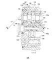
図1は、第1の実施の形態に係る減速装置100を示す断面図である。減速装置100は、センタークランクタイプの偏心揺動型の減速装置である。減速装置100は、例えば産業用ロボットのアームを構成する根本側の第1アームと先端側の第2アームとの関節部に用いられる。減速装置100は、第1アーム内に組み込まれるモータの回転を減速して第2アームに出力することにより、第2アームを第1アームに対して相対回転させる。
(First Embodiment)
FIG. 1 is a cross-sectional view showing a speed reducing device 100 according to the first embodiment. The speed reduction device 100 is a center crank type eccentric swing type speed reduction device. The speed reducing device 100 is used, for example, at a joint portion between a first arm on the root side and a second arm on the tip side, which constitute an arm of an industrial robot. The speed reducing device 100 decelerates the rotation of the motor incorporated in the first arm and outputs it to the second arm, thereby rotating the second arm relative to the first arm.

減速装置100は、入力軸2と、偏心体4、6、8と、ころ10、12、14と、外歯歯車16、18、20と、第1キャリヤ部材26と、第2キャリヤ部材28と、ケーシング36と、主軸受38と、内歯歯車40と、を備える。 The speed reducing device 100 includes an input shaft 2, eccentric bodies 4, 6, 8, rollers 10, 12, 14, external gears 16, 18, 20, a first carrier member 26, and a second carrier member 28. A casing 36, a main bearing 38, and an internal gear 40 are provided.

入力軸2は、例えばモータ等の回転駆動源に接続され、減速装置100(内歯歯車40)の回転軸Rを中心に回転する。入力軸2には、入力軸2と軸心のずれた3つの偏心体4、6、8が一体に形成されている。3つの偏心体4、6、8は、互いに120度の位相差を有して偏心している。なお、偏心体4、6、8は、入力軸2と別体で構成された上で、キー等によって入力軸2に固定されたものであってもよい。 The input shaft 2 is connected to a rotary drive source such as a motor, and rotates about the rotary shaft R of the speed reducer 100 (internal gear 40). The input shaft 2 is integrally formed with the input shaft 2 and three eccentric bodies 4, 6 and 8 whose axes are deviated from each other. The three eccentric bodies 4, 6 and 8 are eccentric with a phase difference of 120 degrees from each other. The eccentric bodies 4, 6 and 8 may be formed separately from the input shaft 2 and then fixed to the input shaft 2 by a key or the like.

各偏心体4、6、8の外周にはそれぞれ、ころ10、12、14を介して、3枚の外歯歯車16、18、20が揺動可能に外嵌されている。外歯歯車16、18、20にはそれぞれ、軸心からオフセットした位置に複数のオフセット貫通孔16a、18a、20aが形成されている。複数のオフセット貫通孔16a、18a、20aは、周方向に等間隔に形成されている。 Three external gears 16, 18 and 20 are swingably fitted on the outer circumferences of the eccentric bodies 4, 6 and 8 via rollers 10, 12 and 14, respectively. A plurality of offset through holes 16a, 18a, 20a are formed in the external gears 16, 18 and 20, respectively, at positions offset from the axis. The plurality of offset through holes 16a, 18a, 20a are formed at equal intervals in the circumferential direction.

オフセット貫通孔16a、18a、20aには、内ピン22および内ピン22に外嵌された内ローラ24が軸方向に貫通される。内ローラ24とオフセット貫通孔16a、18a、20aとの間には、最大で偏心体4、6、8の偏心量の2倍に相当する隙間が確保されている。内ローラ24は、外周面24aが外歯歯車16、18、20のオフセット貫通孔16a、18a、20aと摺動可能に当接するとともに、内周面24bが内ピン22の外周面22aと摺動可能に当接している。 The inner pin 22 and the inner roller 24 fitted on the inner pin 22 are axially penetrated through the offset through holes 16a, 18a, and 20a. A gap corresponding to twice the eccentric amount of the eccentric bodies 4, 6 and 8 is secured at the maximum between the inner roller 24 and the offset through holes 16a, 18a and 20a. In the inner roller 24, the outer peripheral surface 24a is slidably in contact with the offset through holes 16a, 18a, 20a of the outer gears 16, 18, 20 and the inner peripheral surface 24b is slidable with the outer peripheral surface 22a of the inner pin 22. It is in contact with possible.

第1キャリヤ部材26は、外歯歯車16、18、20の軸方向一方側(図1では右側)に配置されている。第1キャリヤ部材26は、ボルト30により内ピン22と締結されている。第2キャリヤ部材28は、外歯歯車16、18、20の軸方向他方側(図1では左側)に配置されている。本実施の形態では、第2キャリヤ部材28は、内ピン22と一体に形成される。したがって、第1キャリヤ部材26と第2キャリヤ部材28とは、内ピン22を介して連結されている。 The first carrier member 26 is arranged on one side in the axial direction (right side in FIG. 1) of the external gears 16, 18, and 20. The first carrier member 26 is fastened to the inner pin 22 by a bolt 30. The second carrier member 28 is arranged on the other side (left side in FIG. 1) of the external gears 16, 18, and 20 in the axial direction. In the present embodiment, the second carrier member 28 is formed integrally with the inner pin 22. Therefore, the first carrier member 26 and the second carrier member 28 are connected via the inner pin 22.

第1キャリヤ部材26と入力軸2との間に軸受32が配置され、第2キャリヤ部材28と入力軸2との間に軸受34が配置される。第1キャリヤ部材26および第2キャリヤ部材28は、軸受32、34を介して入力軸2を回転自在に支持する。 A bearing 32 is arranged between the first carrier member 26 and the input shaft 2, and a bearing 34 is arranged between the second carrier member 28 and the input shaft 2. The first carrier member 26 and the second carrier member 28 rotatably support the input shaft 2 via bearings 32 and 34.

ケーシング36は、略円筒状の部材であり、外歯歯車16、18、20、第1キャリヤ部材26および第2キャリヤ部材28を環囲する。ケーシング36と第2キャリヤ部材28との間には、主軸受38が配置される。ケーシング36と第2キャリヤ部材28は、主軸受38を介して相対回転可能に構成される。 The casing 36 is a substantially cylindrical member and surrounds the external gears 16, 18, 20, the first carrier member 26, and the second carrier member 28. A main bearing 38 is arranged between the casing 36 and the second carrier member 28. The casing 36 and the second carrier member 28 are configured to be relatively rotatable via the main bearing 38.

内歯歯車40は、ケーシング36の内周面に形成されている。内歯歯車40は、外歯歯車16、18、20と内接噛合する。内歯歯車40は、ケーシング36の内周面に形成された等間隔のピン溝に円柱状の外ピンを嵌め込むことで構成される。なお、内歯歯車40をケーシング36の内周面に一体形成してもよい。内歯歯車40の内歯の歯数は、外歯歯車16、18、20の外歯の歯数よりも僅かに(例えば1だけ)多くされている。 The internal gear 40 is formed on the inner peripheral surface of the casing 36. The internal gear 40 internally meshes with the external gears 16, 18, and 20. The internal gear 40 is configured by fitting cylindrical outer pins into pin grooves formed on the inner peripheral surface of the casing 36 at equal intervals. The internal gear 40 may be integrally formed on the inner peripheral surface of the casing 36. The number of internal teeth of the internal gear 40 is slightly (for example, only 1) larger than the number of external teeth of the external gears 16, 18, and 20.

ケーシング36と第2キャリヤ部材28との間には、オイルシール82が設けられる。これにより、減速装置100の内部が封止され、減速装置100内の潤滑剤が漏れるのが抑止される。 An oil seal 82 is provided between the casing 36 and the second carrier member 28. As a result, the inside of the speed reducer 100 is sealed, and leakage of the lubricant in the speed reducer 100 is prevented.

図2(a)〜(c)は、主軸受38を示す拡大断面図である。図2(a)は、テーパころ46の表示を省略した断面図であり、図2(b)は第1テーパころを含む断面図であり、図2(c)は第2テーパころを含む断面図である。図1に加えて図2を参照する。 2 (a) to 2 (c) are enlarged cross-sectional views showing the main bearing 38. FIG. 2A is a cross-sectional view in which the display of the tapered roller 46 is omitted, FIG. 2B is a cross-sectional view including the first tapered roller, and FIG. 2C is a cross-sectional view including the second tapered roller. It is a figure. See FIG. 2 in addition to FIG.

主軸受38は、外輪42と、内輪44と、複数のテーパころ46と、を含む。外輪42は、ケーシング36の内周面に固定される。外輪42は、内周面に、回転軸Rを環囲するよう設けられる転走面42a、42bを有する。転走面42aは軸方向において第1キャリヤ部材側(図2では右側)に位置し、転走面42bは軸方向において第2キャリヤ部材側(図2では左側)に位置する。転走面42aと転走面42bとは、回転軸Rを環囲する環状のV溝を形成する。 The main bearing 38 includes an outer ring 42, an inner ring 44, and a plurality of tapered rollers 46. The outer ring 42 is fixed to the inner peripheral surface of the casing 36. The outer ring 42 has rolling surfaces 42a and 42b provided on the inner peripheral surface so as to surround the rotation shaft R. The rolling surface 42a is located on the first carrier member side (right side in FIG. 2) in the axial direction, and the rolling surface 42b is located on the second carrier member side (left side in FIG. 2) in the axial direction. The rolling surface 42a and the rolling surface 42b form an annular V-groove that surrounds the rotation axis R.

内輪44は、第2キャリヤ部材28の外周面に固定される。内輪44は、外周面に、回転軸Rを環囲するよう設けられる転走面44a、44bを有する。転走面44aは軸方向において第1キャリヤ部材側に位置し、転走面44bは軸方向において第2キャリヤ部材側に位置する。転走面44aと転走面44bとは、回転軸Rを環囲する環状のV溝を形成する。 The inner ring 44 is fixed to the outer peripheral surface of the second carrier member 28. The inner ring 44 has rolling surfaces 44a and 44b provided on the outer peripheral surface so as to surround the rotation shaft R. The rolling surface 44a is located on the first carrier member side in the axial direction, and the rolling surface 44b is located on the second carrier member side in the axial direction. The rolling surface 44a and the rolling surface 44b form an annular V-groove that surrounds the rotation axis R.

転走面42aと転走面44bは、回転軸Rを含む平面において、転走面44aに向かうほど互いに近づくよう構成される。転走面42aと転走面44bは特に、回転軸Rを含む平面において、転走面42aの延長線L1と転走面44bの延長線L2とが、回転軸R上またはその近傍で交わるよう形成される。以下、延長線L1と延長線L2の交点を第1交点P1と呼ぶ。 The rolling surface 42a and the rolling surface 44b are configured to approach each other toward the rolling surface 44a on a plane including the rotation axis R. The rolling surface 42a and the rolling surface 44b are such that the extension line L1 of the rolling surface 42a and the extension line L2 of the rolling surface 44b intersect on or near the rotation axis R, particularly on a plane including the rotation axis R. It is formed. Hereinafter, the intersection of the extension line L1 and the extension line L2 will be referred to as a first intersection P1.

転走面42bと転走面44aは、回転軸Rを含む平面において、転走面44bに向かうほど互いに近づくよう構成される。転走面42bと転走面44aは特に、回転軸Rを含む平面において、転走面42bの延長線L3と転走面44aの延長線L4とが、回転軸R上またはその近傍で交わるよう形成される。以下、延長線L3と延長線L4の交点を第2交点P2と呼ぶ。 The rolling surface 42b and the rolling surface 44a are configured to approach each other toward the rolling surface 44b on a plane including the rotation axis R. The rolling surface 42b and the rolling surface 44a are such that the extension line L3 of the rolling surface 42b and the extension line L4 of the rolling surface 44a intersect on or near the rotation axis R, particularly on a plane including the rotation axis R. It is formed. Hereinafter, the intersection of the extension line L3 and the extension line L4 will be referred to as a second intersection P2.

さらには、軸方向位置について、内歯歯車40と、外歯歯車16、18、20との噛み合い位置の少なくとも一部が、第1交点P1との第2交点P2との間に位置するよう構成される。好ましくは、図1に示すように、外輪42および内輪44は、軸方向位置について、内歯歯車40と、外歯歯車16、18、20との噛み合い位置の全体が、第1交点P1との第2交点P2との間に位置するよう構成される。 Further, with respect to the axial position, at least a part of the meshing position between the internal gear 40 and the external gears 16, 18 and 20 is configured to be located between the first intersection P1 and the second intersection P2. Will be done. Preferably, as shown in FIG. 1, the outer ring 42 and the inner ring 44 have the entire meshing position of the inner gear 40 and the outer gears 16, 18 and 20 in the axial position with respect to the first intersection P1. It is configured to be located between the second intersection P2.

また、軸方向位置について、外歯歯車16、18、20と内ローラ24との接触位置の少なくとも一部が、好ましくはその全部が、第1交点P1との第2交点P2との間に位置するよう構成される。 Further, with respect to the axial position, at least a part, preferably all of the contact positions between the external gears 16, 18, 20 and the inner roller 24 are located between the first intersection P1 and the second intersection P2. It is configured to do.

また、本実施の形態では、軸方向位置について、軸受32、34およびオイルシール82が、第1交点P1との第2交点P2との間に位置するよう構成される。 Further, in the present embodiment, the bearings 32, 34 and the oil seal 82 are configured to be located between the first intersection P1 and the second intersection P2 in the axial position.

複数のテーパころ46はそれぞれ、略円錐台形状を有する。複数のテーパころ46は、転走面42a、42b、44a、44bの間に配置される。具体的には、複数のテーパころ46は、図2(b)のごとく上底側端面(面積が狭い方の端面)46aが内輪44の転走面44aと対向するテーパころ46(以下、「第1テーパころ」と呼ぶ)と、図2(c)のごとく上底側端面46aが内輪44の転走面44bと対向するテーパころ46(以下、「第2テーパころ」と呼ぶ)とが、転走面42a、42b、44a、44bの間に、周方向に交互に並ぶよう配置される。第1テーパころは、転走面42aと転走面44bを転走し、第2テーパころは、転走面42bと内輪44の転走面44aを転走する。 Each of the plurality of tapered rollers 46 has a substantially truncated cone shape. The plurality of tapered rollers 46 are arranged between the rolling surfaces 42a, 42b, 44a, 44b. Specifically, as shown in FIG. 2B, the plurality of tapered rollers 46 have a tapered roller 46 (hereinafter, "" The tapered roller 46 (hereinafter referred to as the "second tapered roller") in which the upper bottom side end surface 46a faces the rolling surface 44b of the inner ring 44 as shown in FIG. 2C. , Are arranged so as to be alternately arranged in the circumferential direction between the rolling surfaces 42a, 42b, 44a, 44b. The first tapered roller rolls on the rolling surface 42a and the rolling surface 44b, and the second tapered roller rolls on the rolling surface 42b and the rolling surface 44a of the inner ring 44.

以上のように構成された減速装置100の動作を説明する。ここでは、外歯歯車16、18、20と内歯歯車40との歯数差が1である場合を例に説明する。 The operation of the speed reducer 100 configured as described above will be described. Here, a case where the difference in the number of teeth between the external gears 16, 18 and 20 and the internal gear 40 is 1 will be described as an example.

入力軸2が回転すると、入力軸2と一体に形成された偏心体4、6、8が回転し、ころ10、12、14を介して外歯歯車16、18、20が揺動する。この揺動により、外歯歯車16、18、20と内歯歯車40の噛合位置が順次ずれてゆく現象が生じる。 When the input shaft 2 rotates, the eccentric bodies 4, 6 and 8 formed integrally with the input shaft 2 rotate, and the external gears 16, 18 and 20 swing via the rollers 10, 12 and 14. Due to this swing, a phenomenon occurs in which the meshing positions of the external gears 16, 18, 20 and the internal gear 40 are sequentially displaced.

外歯歯車16、18、20の歯数は、内歯歯車40の歯数よりも1だけ少ないため、外歯歯車16、18、20は、入力軸2が1回回転するごとに、1歯分(すなわち歯数差に相当する分)だけ内歯歯車40に対して位相がずれる(自転する)ことになる。この自転成分は、外歯歯車16、18、20のオフセット貫通孔16a、18a、20aと内ローラ24との摺動、および内ローラ24の内周面24bと内ピン22の外周面22aとの摺動を介して内ピン22に伝達され、内ピン22と一体に形成された第2キャリヤ部材28が1/(内歯歯車の歯数)に減速された回転速度にてケーシング36に対して相対回転する。したがって、ケーシング36が固定されている場合は第2キャリヤ部材28が回転し、第2キャリヤ部材28が固定されている場合はケーシング36が回転する。 Since the number of teeth of the external gears 16, 18 and 20 is one less than the number of teeth of the internal gear 40, the external gears 16, 18 and 20 have one tooth each time the input shaft 2 rotates once. The phase is shifted (rotated) with respect to the internal gear 40 by a minute (that is, a portion corresponding to the difference in the number of teeth). This rotation component comprises sliding the offset through holes 16a, 18a, 20a of the external gears 16, 18 and 20 with the inner roller 24, and the inner peripheral surface 24b of the inner roller 24 and the outer peripheral surface 22a of the inner pin 22. The second carrier member 28, which is transmitted to the inner pin 22 via sliding and is integrally formed with the inner pin 22, is reduced to 1 / (the number of teeth of the internal gear) with respect to the casing 36. Relative rotation. Therefore, when the casing 36 is fixed, the second carrier member 28 rotates, and when the second carrier member 28 is fixed, the casing 36 rotates.

以上説明した第1の実施の形態に係る減速装置100によれば、主軸受38は、従来のクロスローラ軸受とは異なり、テーパころ46が円錐台形状を有する。この場合、テーパころ46は、外輪42と内輪44との間を転がりながら移動する。そのため、主軸受38に内部予圧を与えても回転トルクが飛躍的に高くなったり、すべりによる著しい寿命低下の問題は生じない。したがって、主軸受38に内部予圧を与えることができ、モーメント剛性を高めることができる。つまり、小型でありながらも主軸受のモーメント剛性の高い減速装置100を実現できる。 According to the reduction gear 100 according to the first embodiment described above, the main bearing 38 has a truncated cone shape with the tapered roller 46, unlike the conventional cross roller bearing. In this case, the taper roller 46 moves while rolling between the outer ring 42 and the inner ring 44. Therefore, even if an internal preload is applied to the main bearing 38, there is no problem that the rotational torque is dramatically increased and the life is significantly shortened due to slippage. Therefore, an internal preload can be applied to the main bearing 38, and the moment rigidity can be increased. That is, it is possible to realize the reduction gear 100 which is small in size but has high moment rigidity of the main bearing.

また、減速装置100によれば、軸方向位置について、第1交点P1と第2交点P2の間に、内歯歯車40と外歯歯車16、18、20との噛み合い部の少なくとも一部が位置する。また、軸方向位置について、第1交点P1と第2交点P2の間に、外歯歯車16、18、20と内ローラ24との接触位置の少なくとも一部が位置する。ここで、第1交点P1および第2交点P2は、モーメント荷重の作用点であり、軸方向について、それらの間にモーメント荷重の影響を大きく受ける出力の取り出し部分が位置するようにすることで、モーメント荷重が噛み合いに与える影響を最小限に抑えることができる。 Further, according to the reduction gear 100, at least a part of the meshing portion between the internal gear 40 and the external gears 16, 18 and 20 is located between the first intersection P1 and the second intersection P2 in the axial position. do. Further, regarding the axial position, at least a part of the contact position between the external gears 16, 18, 20 and the inner roller 24 is located between the first intersection P1 and the second intersection P2. Here, the first intersection P1 and the second intersection P2 are the points of action of the moment load, and the output extraction portion that is greatly affected by the moment load is located between them in the axial direction. The influence of the moment load on the meshing can be minimized.

また、減速装置100によれば、軸方向位置について、第1交点P1と第2交点P2の間に軸受32、34が位置する。また、軸方向位置について、第1交点P1と第2交点P2の間にオイルシール82が位置する。これにより、モーメント荷重が軸受32、34やオイルシール82に与える影響を最小限に抑えることができる Further, according to the speed reducing device 100, the bearings 32 and 34 are located between the first intersection P1 and the second intersection P2 in the axial position. Further, regarding the axial position, the oil seal 82 is located between the first intersection P1 and the second intersection P2. As a result, the influence of the moment load on the bearings 32 and 34 and the oil seal 82 can be minimized.

(第2の実施の形態)
図3は、第2の実施の形態に係る減速装置200を示す断面図である。減速装置200は、振り分けタイプの偏心揺動型の減速装置である。
(Second Embodiment)
FIG. 3 is a cross-sectional view showing a speed reducing device 200 according to the second embodiment. The speed reducer 200 is a distribution type eccentric swing type speed reducer.

減速装置200は、入力軸102と、偏心体104、106と、ころ110、112と、外歯歯車116、118と、第1キャリヤ部材126と、第2キャリヤ部材128と、ケーシング136と、主軸受138と、内歯歯車140と、偏心体軸歯車150と、偏心体軸152と、を備える。 The speed reducer 200 includes an input shaft 102, eccentric bodies 104 and 106, rollers 110 and 112, external gears 116 and 118, a first carrier member 126, a second carrier member 128, a casing 136, and a main body. A bearing 138, an internal gear 140, an eccentric shaft gear 150, and an eccentric shaft 152 are provided.

偏心体軸152は、減速装置200(内歯歯車140)の回転軸Rの周りに等間隔に複数(例えば3本)設けられる。各偏心体軸152は、入力軸102と平行に配置される。 A plurality (for example, three) of eccentric body shafts 152 are provided around the rotation shaft R of the speed reducing device 200 (internal gear 140) at equal intervals. Each eccentric body axis 152 is arranged parallel to the input axis 102.

入力軸102は、例えばモータ等の回転駆動源に接続され、回転軸Rを中心に回転する。入力軸102の先端には、入力ピニオン102aが形成されており、偏心体軸152と同数の偏心体軸歯車150が入力ピニオン102aに噛合している。複数の偏心体軸歯車150はそれぞれ、対応する偏心体軸152の端部に形成されたスプライン152aとスプライン結合されるとともに、止め輪(不図示)によって軸方向の移動が規制されている。 The input shaft 102 is connected to a rotation drive source such as a motor, and rotates about the rotation shaft R. An input pinion 102a is formed at the tip of the input shaft 102, and the same number of eccentric shaft gears 150 as the eccentric shaft 152 mesh with the input pinion 102a. Each of the plurality of eccentric shaft gears 150 is spline-coupled to a spline 152a formed at the end of the corresponding eccentric shaft 152, and axial movement is restricted by a retaining ring (not shown).

偏心体軸152には、偏心体軸152と軸心のずれた2つの偏心体104、106が一体に形成されている。2つの偏心体104、106は、互いに180度の位相差を有して偏心している。複数(例えば3本)の偏心体軸152は、それぞれの偏心体104、106の偏心方向が互いに一致するように組み付けられる。なお、偏心体104、106は、偏心体軸152と別体で構成された上で、キー等によって偏心体軸152に固定されたものであってもよい。 The eccentric body shaft 152 is integrally formed with the eccentric body shaft 152 and two eccentric bodies 104 and 106 whose axes are deviated from each other. The two eccentric bodies 104 and 106 are eccentric with a phase difference of 180 degrees from each other. A plurality of (for example, three) eccentric body axes 152 are assembled so that the eccentric directions of the eccentric bodies 104 and 106 coincide with each other. The eccentric bodies 104 and 106 may be formed separately from the eccentric body shaft 152 and then fixed to the eccentric body shaft 152 by a key or the like.

各偏心体104、106の外周にはそれぞれ、ころ110、112を介して、2枚の外歯歯車116、118が揺動可能に外嵌されている。外歯歯車116、118にはそれぞれ、軸心からオフセットした位置に、複数の第1貫通孔116a、118aと複数の第2貫通孔116b、118bが形成されている。複数の第1貫通孔116a、118aは、周方向に等間隔に形成されており、偏心体軸152が貫通する。第2貫通孔116b、118bは、周方向に等間隔に形成されており、第2キャリヤ部材128の凸部128a(後述)が貫通する。 Two external gears 116 and 118 are swingably fitted on the outer circumferences of the eccentric bodies 104 and 106 via rollers 110 and 112, respectively. The external tooth gears 116 and 118 are formed with a plurality of first through holes 116a and 118a and a plurality of second through holes 116b and 118b at positions offset from the axial center, respectively. The plurality of first through holes 116a and 118a are formed at equal intervals in the circumferential direction, and the eccentric body shaft 152 penetrates therethrough. The second through holes 116b and 118b are formed at equal intervals in the circumferential direction, and the convex portions 128a (described later) of the second carrier member 128 penetrate.

第1キャリヤ部材126は、略円板形状を有し、外歯歯車116、118の軸方向一方側(図3では右側)に配置されている。第2キャリヤ部材128は、外歯歯車116、118の軸方向他方側(図3では左側)に配置されている。 The first carrier member 126 has a substantially disk shape and is arranged on one side (right side in FIG. 3) of the external gears 116 and 118 in the axial direction. The second carrier member 128 is arranged on the other side (left side in FIG. 3) of the external gears 116 and 118 in the axial direction.

第2キャリヤ部材128には、外歯歯車116、118の第2貫通孔116b、118bに隙間を有した状態で挿通され、第1キャリヤ部材126側に向けて軸方向に延びる複数の凸部(柱部)128aが周方向に等間隔に設けられている。第1キャリヤ部材126と第2キャリヤ部材128の凸部128aの先端部は、ボルト130により締結される。これにより、第1キャリヤ部材126と第2キャリヤ部材128は、一体的に回転する。 The second carrier member 128 is inserted through the second through holes 116b and 118b of the external gears 116 and 118 with a gap, and a plurality of convex portions extending in the axial direction toward the first carrier member 126 side (a plurality of convex portions ( Pillar portions) 128a are provided at equal intervals in the circumferential direction. The tip ends of the convex portion 128a of the first carrier member 126 and the second carrier member 128 are fastened by bolts 130. As a result, the first carrier member 126 and the second carrier member 128 rotate integrally.

第1キャリヤ部材126と偏心体軸152との間に軸受132が配置され、第2キャリヤ部材128と入力軸2との間に軸受134が配置される。第1キャリヤ部材126および第2キャリヤ部材128は、軸受132、134を介して、偏心体軸152を回転自在に支持する。 The bearing 132 is arranged between the first carrier member 126 and the eccentric body shaft 152, and the bearing 134 is arranged between the second carrier member 128 and the input shaft 2. The first carrier member 126 and the second carrier member 128 rotatably support the eccentric body shaft 152 via bearings 132 and 134.

ケーシング136は、略円筒状の部材であり、外歯歯車116、118、第1キャリヤ部材126および第2キャリヤ部材128を環囲する。ケーシング136と第2キャリヤ部材128との間には、主軸受138が配置される。ケーシング36と第2キャリヤ部材128は、主軸受138を介して相対回転可能に構成される。 The casing 136 is a substantially cylindrical member, and surrounds the external gears 116 and 118, the first carrier member 126, and the second carrier member 128. A main bearing 138 is arranged between the casing 136 and the second carrier member 128. The casing 36 and the second carrier member 128 are configured to be relatively rotatable via the main bearing 138.

内歯歯車140は、ケーシング136の内周面に形成されている。内歯歯車140は、外歯歯車116、118と内接噛合する。内歯歯車140は、ケーシング136の内周面に形成された等間隔のピン溝に円柱状の外ピンを嵌め込むことで構成される。なお、内歯歯車140をケーシング136の内周面に一体形成してもよい。内歯歯車140の内歯の歯数は、外歯歯車116、118の外歯の歯数よりも僅かに(例えば1だけ)多くされている。 The internal gear 140 is formed on the inner peripheral surface of the casing 136. The internal gear 140 internally meshes with the external gears 116 and 118. The internal gear 140 is configured by fitting cylindrical outer pins into pin grooves formed on the inner peripheral surface of the casing 136 at equal intervals. The internal gear 140 may be integrally formed on the inner peripheral surface of the casing 136. The number of internal teeth of the internal gear 140 is slightly (for example, only 1) larger than the number of external teeth of the external gears 116 and 118.

ケーシング136と第2キャリヤ部材128との間にオイルシール182が設けられ、第2キャリヤ部材128と入力軸102との間にオイルシール184が設けられる。これにより、減速装置200の内部が封止され、減速装置200内の潤滑剤が漏れるのが抑止される。 An oil seal 182 is provided between the casing 136 and the second carrier member 128, and an oil seal 184 is provided between the second carrier member 128 and the input shaft 102. As a result, the inside of the speed reducer 200 is sealed, and the leakage of the lubricant in the speed reducer 200 is suppressed.

主軸受138は、外輪142と、内輪144と、複数のテーパころ146と、を含む。外輪142、内輪144、テーパころ146はそれぞれ、外輪42、内輪44、テーパころ46と同様に構成される。 The main bearing 138 includes an outer ring 142, an inner ring 144, and a plurality of tapered rollers 146. The outer ring 142, the inner ring 144, and the tapered roller 146 are configured in the same manner as the outer ring 42, the inner ring 44, and the tapered roller 46, respectively.

本実施の形態では、軸方向位置について、内歯歯車140と、外歯歯車116、118との噛み合い位置の少なくとも一部が、好ましくは噛み合い位置の全部が、第1交点P1と第2交点P2との間に位置するよう構成される。また、軸方向位置について、外歯歯車116と、第2キャリヤ部材128の凸部128aとの接触位置の少なくとも一部、好ましくは全部が、第1交点P1との第2交点P2との間に位置するよう構成される。また、軸方向位置について、入力軸102の入力軸102と偏心体軸歯車150との噛み合い位置の少なくとも一部が、好ましくは噛み合い位置の全部が、第1交点P1と第2交点P2との間に位置するよう構成される。また、外輪142および内輪144は、軸方向位置について、軸受132、134およびオイルシール182、184が、第1交点P1との第2交点P2との間に位置するよう形成される。 In the present embodiment, with respect to the axial position, at least a part of the meshing positions of the internal gear 140 and the external gears 116 and 118, preferably all of the meshing positions, are the first intersection P1 and the second intersection P2. It is configured to be located between and. Further, regarding the axial position, at least a part, preferably all of the contact positions between the external gear 116 and the convex portion 128a of the second carrier member 128 are between the first intersection P1 and the second intersection P2. Configured to be located. Further, regarding the axial position, at least a part of the meshing position between the input shaft 102 of the input shaft 102 and the eccentric shaft gear 150, preferably the entire meshing position, is between the first intersection P1 and the second intersection P2. It is configured to be located in. Further, the outer ring 142 and the inner ring 144 are formed so that the bearings 132 and 134 and the oil seals 182 and 184 are located between the first intersection P1 and the second intersection P2 in the axial position.

以上のように構成された減速装置200の動作を説明する。ここでは、外歯歯車116、118と内歯歯車140との歯数差が1である場合を例に説明する。 The operation of the speed reducer 200 configured as described above will be described. Here, a case where the difference in the number of teeth between the external gears 116 and 118 and the internal gear 140 is 1 will be described as an example.

入力軸102が回転すると、入力軸102の入力ピニオン102aに噛合している複数の偏心体軸歯車150が回転(自転)し、複数の偏心体軸歯車150のそれぞれに連結されている偏心体軸152が回転(自転)する。 When the input shaft 102 rotates, the plurality of eccentric body shaft gears 150 meshing with the input pinion 102a of the input shaft 102 rotate (rotate), and the eccentric body shafts connected to each of the plurality of eccentric body shaft gears 150. 152 rotates (rotates).

偏心体軸152が回転すると、入力軸2と一体に形成された偏心体104、106が回転し、ころ110、112を介して外歯歯車116、118が揺動する。この揺動により、外歯歯車116、118と内歯歯車140の噛合位置が順次ずれてゆく現象が生じる。 When the eccentric body shaft 152 rotates, the eccentric bodies 104 and 106 formed integrally with the input shaft 2 rotate, and the external gears 116 and 118 swing via the rollers 110 and 112. Due to this swing, a phenomenon occurs in which the meshing positions of the external gears 116 and 118 and the internal gear 140 are sequentially displaced.

外歯歯車116、118の歯数は、内歯歯車140の歯数よりも1だけ少ないため、外歯歯車116、118は、偏心体軸152が1回回転するごとに、1歯分(すなわち歯数差に相当する分)だけ内歯歯車140に対して位相がずれる(自転する)ことになる。この結果、偏心体軸152が回転軸Rの周りを公転し、偏心体軸152を支持している第1キャリヤ部材126、第2キャリヤ部材128がケーシング136に対して相対的に回転する。したがって、ケーシング136が固定されている場合は第2キャリヤ部材128が回転し、第2キャリヤ部材128が固定されている場合はケーシング136が回転する。 Since the number of teeth of the external gears 116 and 118 is one less than the number of teeth of the internal gear 140, the external gears 116 and 118 have one tooth (that is, one tooth) for each rotation of the eccentric body shaft 152. The phase is shifted (rotated) with respect to the internal gear 140 by the amount corresponding to the difference in the number of teeth. As a result, the eccentric body shaft 152 revolves around the rotation shaft R, and the first carrier member 126 and the second carrier member 128 supporting the eccentric body shaft 152 rotate relative to the casing 136. Therefore, when the casing 136 is fixed, the second carrier member 128 rotates, and when the second carrier member 128 is fixed, the casing 136 rotates.

以上説明した第2の実施の形態に係る減速装置200によれば、第1の実施の形態に係る減速装置100と同様に、主軸受138に内部予圧を与えることができ、モーメント剛性を高めることができる。つまり、小型でありながらも主軸受のモーメント剛性の高い減速装置200を実現できる。 According to the speed reducing device 200 according to the second embodiment described above, the internal preload can be applied to the main bearing 138 and the moment rigidity is increased as in the speed reducing device 100 according to the first embodiment. Can be done. That is, it is possible to realize a reduction gear 200 which is small in size but has high moment rigidity of the main bearing.

また、減速装置200によれば、第1の実施の形態に係る減速装置100と同様に、軸方向位置について、第1交点P1と第2交点P2との間にモーメント荷重の影響を大きく受ける出力の取り出し部分が位置するようにすることで、モーメント荷重が噛み合いに与える影響を最小限に抑えることができる。 Further, according to the speed reducer 200, similarly to the speed reducer 100 according to the first embodiment, the output is greatly affected by the moment load between the first intersection P1 and the second intersection P2 with respect to the axial position. By locating the take-out portion of, the influence of the moment load on the meshing can be minimized.

また、減速装置200によれば、第1の実施の形態に係る減速装置100と同様に、軸方向位置について、第1交点P1と第2交点P2との間に軸受やオイルシールが位置するようにすることで、モーメント荷重がこれらに与える影響を最小限に抑えることができる。 Further, according to the speed reducer 200, similarly to the speed reducer 100 according to the first embodiment, the bearing and the oil seal are positioned between the first intersection P1 and the second intersection P2 in the axial position. By setting, the influence of the moment load on these can be minimized.

(第3の実施の形態)
図4は、第3の実施の形態に係る減速装置300を示す断面図である。減速装置300は、フラットタイプの撓み噛合い式の減速装置である。
(Third Embodiment)
FIG. 4 is a cross-sectional view showing a speed reducing device 300 according to a third embodiment. The speed reducing device 300 is a flat type flexible meshing type speed reducing device.

減速装置300は、波動発生器260と、外歯歯車216と、内歯歯車240と、キャリヤ部材226と、ケーシング236と、主軸受238と、第1軸受ハウジング272と、第2軸受ハウジング274と、を備える。 The reduction gear 300 includes a wave generator 260, an external gear 216, an internal gear 240, a carrier member 226, a casing 236, a main bearing 238, a first bearing housing 272, and a second bearing housing 274. , Equipped with.

波動発生器260は、入力軸202と、複数の第1転動体262aと、複数の第2転動体262bと、第1保持器264aと、第2保持器264bと、第1外輪部材266aと、第2外輪部材266bとを含む。入力軸202は、例えばモータ等の回転駆動源に接続され、減速装置300(内歯歯車240)の回転軸Rを中心に回転する。入力軸202には、回転軸Rに直交する断面が略楕円形状である起振体202aが一体に形成されている。 The wave generator 260 includes an input shaft 202, a plurality of first rolling elements 262a, a plurality of second rolling elements 262b, a first cage 264a, a second cage 264b, a first outer ring member 266a, and the like. Includes a second outer ring member 266b. The input shaft 202 is connected to a rotation drive source such as a motor, and rotates about the rotation shaft R of the reduction gear 300 (internal gear 240). A vibrator 202a having a substantially elliptical cross section orthogonal to the rotation axis R is integrally formed on the input shaft 202.

複数の第1転動体262aはそれぞれ、略円柱形状を有し、軸方向が回転軸R方向と略平行な方向を向いた状態で周方向に間隔を空けて設けられる。第1転動体262aは、第1保持器264aにより転動自在に保持され、起振体202aの外周面202bを転走する。第2転動体262bは、第1転動体262aと同様に構成される。複数の第2転動体262bは、第1保持器264aと軸方向に並ぶように配置された第2保持器264bにより転動自在に保持され、起振体202aの外周面202bを転走する。以降では、第1転動体262aと第2転動体262bとをまとめて「転動体262」とも呼ぶ。また、第1保持器264aと第2保持器264bとをまとめて「保持器264」とも呼ぶ Each of the plurality of first rolling elements 262a has a substantially cylindrical shape, and is provided at intervals in the circumferential direction in a state in which the axial direction is oriented substantially parallel to the rotation axis R direction. The first rolling element 262a is rotatably held by the first cage 264a and rolls on the outer peripheral surface 202b of the oscillating body 202a. The second rolling element 262b is configured in the same manner as the first rolling element 262a. The plurality of second rolling elements 262b are rotatably held by the second cage 264b arranged so as to be aligned with the first cage 264a in the axial direction, and roll on the outer peripheral surface 202b of the oscillating body 202a. Hereinafter, the first rolling element 262a and the second rolling element 262b are collectively referred to as a “rolling body 262”. Further, the first cage 264a and the second cage 264b are collectively referred to as "retainer 264".

第1外輪部材266aは、複数の第1転動体262aを環囲する。第1外輪部材266aは、可撓性を有し、複数の第1転動体262aを介して起振体202aにより楕円状に撓められる。第1外輪部材266aは、起振体202a(すなわち入力軸202)が回転すると、起振体202aの形状に合わせて連続的に変形する。第2外輪部材266bは、第1外輪部材266aと同様に構成される。第2外輪部材266bは、第1外輪部材266aとは別体として形成される。なお、第2外輪部材266bは、第1外輪部材266aと一体に形成されてもよい。以降では、第1外輪部材266aと第2外輪部材266bとをまとめて「外輪部材266」とも呼ぶ。 The first outer ring member 266a surrounds a plurality of first rolling elements 262a. The first outer ring member 266a has flexibility and is elliptically bent by the oscillating body 202a via the plurality of first rolling elements 262a. When the exciter 202a (that is, the input shaft 202) rotates, the first outer ring member 266a is continuously deformed according to the shape of the exciter 202a. The second outer ring member 266b is configured in the same manner as the first outer ring member 266a. The second outer ring member 266b is formed as a separate body from the first outer ring member 266a. The second outer ring member 266b may be integrally formed with the first outer ring member 266a. Hereinafter, the first outer ring member 266a and the second outer ring member 266b are collectively referred to as "outer ring member 266".

外歯歯車216は、可撓性を有する環状の部材であり、その内側には起振体202a、転動体262および外輪部材266が嵌まる。これにより、外歯歯車216は、楕円状に撓められる。外歯歯車216は、起振体202aが回転すると、起振体202aの形状に合わせて連続的に変形する。外歯歯車216は、第1外歯部216aと、第2外歯部216bと、基材216cと、を含む。第1外歯部216aと第2外歯部216bとは単一の基材である基材216cに形成されており、同歯数である。 The external tooth gear 216 is a flexible annular member, and a vibrating body 202a, a rolling element 262, and an outer ring member 266 are fitted inside the external gear 216. As a result, the external gear 216 is bent in an elliptical shape. When the oscillating body 202a rotates, the external tooth gear 216 is continuously deformed according to the shape of the oscillating body 202a. The external tooth gear 216 includes a first external tooth portion 216a, a second external tooth portion 216b, and a base material 216c. The first external tooth portion 216a and the second external tooth portion 216b are formed on a base material 216c which is a single base material, and have the same number of teeth.

内歯歯車240は、剛性を有する環状の部材である。内歯歯車240の第1内歯部240aは、楕円状に撓められた外歯歯車216の第1外歯部216aを環囲し、起振体202aの長軸近傍の所定領域で第1外歯部216aと噛み合う。第1内歯部240aは、第1外歯部216aよりも多くの歯を有する。 The internal gear 240 is an annular member having rigidity. The first internal tooth portion 240a of the internal tooth gear 240 surrounds the first external tooth portion 216a of the external tooth gear 216 bent in an elliptical shape, and is the first in a predetermined region near the long axis of the exciter 202a. It meshes with the external tooth portion 216a. The first internal tooth portion 240a has more teeth than the first external tooth portion 216a.

キャリヤ部材226は、剛性を有する円筒状の部材である。本実施の形態では、キャリヤ部材226の内周面に第2内歯部226aが形成されている。キャリヤ部材226の第2内歯部226aは、楕円状に撓められた外歯歯車216の第2外歯部216bを環囲し、起振体202aの長軸方向の2領域で第2外歯部216bと噛み合う。第2内歯部226aは、第2外歯部216bと同数の歯を有する。したがって、キャリヤ部材226は、第2外歯部216bひいては外歯歯車216の自転と同期して回転する。 The carrier member 226 is a rigid cylindrical member. In the present embodiment, the second internal tooth portion 226a is formed on the inner peripheral surface of the carrier member 226. The second internal tooth portion 226a of the carrier member 226 surrounds the second external tooth portion 216b of the external tooth gear 216 bent in an elliptical shape, and the second outer tooth portion is formed in two regions in the major axis direction of the exciter 202a. It meshes with the tooth portion 216b. The second internal tooth portion 226a has the same number of teeth as the second external tooth portion 216b. Therefore, the carrier member 226 rotates in synchronization with the rotation of the second external tooth portion 216b and thus the external tooth gear 216.

ケーシング236は、略円筒状の部材であり、キャリヤ部材226を環囲する。ケーシング236には、内歯歯車240がインロー嵌合により連結されて一体化される。ケーシング236とキャリヤ部材226は、主軸受238を介して相対回転可能に構成される。 The casing 236 is a substantially cylindrical member and surrounds the carrier member 226. The internal gear 240 is connected and integrated with the casing 236 by inlay fitting. The casing 236 and the carrier member 226 are configured to be relatively rotatable via the main bearing 238.

第1軸受ハウジング272は、環状の部材であり、入力軸202を環囲する。同様に、第2軸受ハウジング274は、環状の部材であり、入力軸202を環囲する。第1軸受ハウジング272と第2軸受ハウジング274とは、外歯歯車216および内歯歯車240を軸方向に挟むよう配置される。第1軸受ハウジング272は、インロー嵌合により内歯歯車240に連結される。第2軸受ハウジング274は、インロー嵌合によりキャリヤ部材226に連結される。 The first bearing housing 272 is an annular member and surrounds the input shaft 202. Similarly, the second bearing housing 274 is an annular member and surrounds the input shaft 202. The first bearing housing 272 and the second bearing housing 274 are arranged so as to sandwich the external gear 216 and the internal gear 240 in the axial direction. The first bearing housing 272 is connected to the internal gear 240 by inlay fitting. The second bearing housing 274 is connected to the carrier member 226 by inlay fitting.

第1軸受ハウジング272には軸受232が組み込まれ、第2軸受ハウジング274には軸受234が組み込まれている。そして、第1軸受ハウジング272および第2軸受ハウジング274は、軸受232、234を介して、入力軸202を回転自在に支持する。 The bearing 232 is incorporated in the first bearing housing 272, and the bearing 234 is incorporated in the second bearing housing 274. The first bearing housing 272 and the second bearing housing 274 rotatably support the input shaft 202 via the bearings 232 and 234.

入力軸202と第1軸受ハウジング272の間にはオイルシール282が配置され、ケーシング236とキャリヤ部材226との間にはオイルシール284が配置され、第2軸受ハウジング274と入力軸202との間にはオイルシール286が配置される。また、第1軸受ハウジング272と内歯歯車240の間にはOリング288が配置され、内歯歯車240とケーシング236との間にはOリング290が配置され、キャリヤ部材226と第2軸受ハウジング274との間にはOリング292が配置される。これらにより、減速装置300内の潤滑剤が漏れるのを抑止できる。 An oil seal 282 is arranged between the input shaft 202 and the first bearing housing 272, an oil seal 284 is arranged between the casing 236 and the carrier member 226, and between the second bearing housing 274 and the input shaft 202. An oil seal 286 is arranged in the housing. Further, an O-ring 288 is arranged between the first bearing housing 272 and the internal gear 240, an O-ring 290 is arranged between the internal gear 240 and the casing 236, and the carrier member 226 and the second bearing housing are arranged. An O-ring 292 is arranged between the 274 and the O-ring 292. As a result, it is possible to prevent the lubricant in the speed reducer 300 from leaking.

主軸受238は、外輪242と、内輪244と、複数のテーパころ246と、を含む。本実施の形態では、外輪242は、ケーシング236の内周面側にケーシング236と一体に形成され、内輪244は、キャリヤ部材226の外周面にキャリヤ部材226と一体に形成される。外輪242、内輪244、テーパころ246はそれぞれ、外輪42、内輪44、テーパころ46と同様に構成される。 The main bearing 238 includes an outer ring 242, an inner ring 244, and a plurality of tapered rollers 246. In the present embodiment, the outer ring 242 is integrally formed with the casing 236 on the inner peripheral surface side of the casing 236, and the inner ring 244 is integrally formed with the carrier member 226 on the outer peripheral surface of the carrier member 226. The outer ring 242, the inner ring 244, and the tapered roller 246 are configured in the same manner as the outer ring 42, the inner ring 44, and the tapered roller 46, respectively.

本実施の形態では、軸方向位置について、内歯歯車240の第1内歯部240aおよびキャリヤ部材226の第2内歯部226aと、外歯歯車216との噛み合い位置の少なくとも一部が、好ましくは噛み合い位置の全部が、第1交点P1と第2交点P2との間に位置するよう構成される。また、軸方向位置について、軸受232、234、オイルシール282、284、286が、第1交点P1との第2交点P2との間に位置するよう構成される。 In the present embodiment, with respect to the axial position, at least a part of the meshing position between the first internal tooth portion 240a of the internal gear 240 and the second internal tooth portion 226a of the carrier member 226 and the external gear 216 is preferable. Is configured so that all of the meshing positions are located between the first intersection P1 and the second intersection P2. Further, with respect to the axial position, the bearings 232, 234 and the oil seals 282, 284, 286 are configured to be located between the first intersection P1 and the second intersection P2.

以上のように構成された減速装置300の動作を説明する。ここでは、第1外歯部216aの歯数が100、第2外歯部216bの歯数が100、第1内歯部240aの歯数が102、第2内歯部226aの歯数が100の場合を例に説明する。また、内歯歯車240および第1軸受ハウジング272が固定状態にある場合を例に説明する。 The operation of the speed reducer 300 configured as described above will be described. Here, the number of teeth of the first external tooth portion 216a is 100, the number of teeth of the second external tooth portion 216b is 100, the number of teeth of the first internal tooth portion 240a is 102, and the number of teeth of the second internal tooth portion 226a is 100. The case of is described as an example. Further, a case where the internal gear 240 and the first bearing housing 272 are in a fixed state will be described as an example.

第1外歯部216aが楕円形状の長軸方向の2箇所で第1内歯部240aと噛み合っている状態で、入力軸202が回転すると、これに伴って第1外歯部216aと第1内歯部240aとの噛み合い位置も周方向に移動する。第1外歯部216aと第1内歯部240aとは歯数が異なるため、この際、第1内歯部240aに対して第1外歯部216aが相対的に回転する。内歯歯車240および第1軸受ハウジング272が固定状態にあるため、第1外歯部216aは、歯数差に相当する分だけ自転することになる。つまり、入力軸202の回転が大幅に減速されて第1外歯部216aに出力される。その減速比は以下のようになる。
減速比=(第1外歯部216aの歯数−第1内歯部240aの歯数)/第1外歯部216aの歯数
=(100−102)/100
=−1/50
When the input shaft 202 rotates while the first external tooth portion 216a is in mesh with the first internal tooth portion 240a at two points in the elliptical shape in the long axis direction, the first external tooth portion 216a and the first external tooth portion 216a and the first The meshing position with the internal tooth portion 240a also moves in the circumferential direction. Since the number of teeth is different between the first external tooth portion 216a and the first internal tooth portion 240a, at this time, the first external tooth portion 216a rotates relative to the first internal tooth portion 240a. Since the internal gear 240 and the first bearing housing 272 are in the fixed state, the first external tooth portion 216a rotates by the amount corresponding to the difference in the number of teeth. That is, the rotation of the input shaft 202 is significantly decelerated and output to the first external tooth portion 216a. The reduction ratio is as follows.
Reduction ratio = (number of teeth of the first external tooth portion 216a-number of teeth of the first internal tooth portion 240a) / number of teeth of the first external tooth portion 216a = (100-102) / 100
= -1/50

第2外歯部216bは、第1外歯部216aと一体的に形成されているため、第1外歯部216aと一体に回転する。第2外歯部216bと第2内歯部226aは歯数が同一であるため、相対回転は発生せず、第2外歯部216bと第2内歯部8aとは一体に回転する。このため、第1外歯部216aの自転と同一の回転が第2内歯部226aすなわちキャリヤ部材226に出力される。結果として、キャリヤ部材226からは入力軸202の回転を−1/50に減速した出力を取り出すことができる。 Since the second external tooth portion 216b is integrally formed with the first external tooth portion 216a, the second external tooth portion 216b rotates integrally with the first external tooth portion 216a. Since the second external tooth portion 216b and the second internal tooth portion 226a have the same number of teeth, relative rotation does not occur, and the second external tooth portion 216b and the second internal tooth portion 8a rotate integrally. Therefore, the same rotation as the rotation of the first external tooth portion 216a is output to the second internal tooth portion 226a, that is, the carrier member 226. As a result, the output obtained by reducing the rotation of the input shaft 202 to -1/50 can be taken out from the carrier member 226.

以上説明した第3の実施の形態に係る減速装置300によれば、第1の実施の形態に係る減速装置100と同様に、主軸受238に内部予圧を与えることができ、モーメント剛性を高めることができる。つまり、小型でありながらも主軸受のモーメント剛性の高い減速装置300を実現できる。 According to the speed reducing device 300 according to the third embodiment described above, the internal preload can be applied to the main bearing 238 and the moment rigidity is increased as in the speed reducing device 100 according to the first embodiment. Can be done. That is, it is possible to realize a reduction gear 300 which is small in size but has high moment rigidity of the main bearing.

また、減速装置300によれば、第1の実施の形態に係る減速装置100と同様に、軸方向位置について、第1交点P1と第2交点P2との間にモーメント荷重の影響を大きく受ける出力の取り出し部分が位置するようにすることで、モーメント荷重が噛み合いに与える影響を最小限に抑えることができる。 Further, according to the speed reducer 300, similarly to the speed reducer 100 according to the first embodiment, the output is greatly affected by the moment load between the first intersection P1 and the second intersection P2 with respect to the axial position. By locating the take-out portion of, the influence of the moment load on the meshing can be minimized.

また、減速装置300によれば、第1の実施の形態に係る減速装置100と同様に、軸方向位置について、第1交点P1と第2交点P2との間に軸受やオイルシールやOリングが位置するようにすることで、モーメント荷重がこれらに与える影響を最小限に抑えることができる。 Further, according to the speed reducer 300, similarly to the speed reducer 100 according to the first embodiment, a bearing, an oil seal, or an O-ring is provided between the first intersection P1 and the second intersection P2 in the axial position. By positioning them, the influence of the moment load on them can be minimized.

(第4の実施の形態)
図5は、第4の実施の形態に係る減速装置400を示す断面図である。減速装置400は、シルクハットタイプの撓み噛合い式の減速装置である。
(Fourth Embodiment)
FIG. 5 is a cross-sectional view showing a speed reducing device 400 according to a fourth embodiment. The speed reducing device 400 is a top hat type bending mesh speed reducing device.

減速装置400は、波動発生器360と、外歯歯車316と、内歯歯車340と、キャリヤ部材326と、ケーシング336と、主軸受338と、第1軸受ハウジング372と、第2軸受ハウジング374と、を備える。 The reduction gear 400 includes a wave generator 360, an external gear 316, an internal gear 340, a carrier member 326, a casing 336, a main bearing 338, a first bearing housing 372, and a second bearing housing 374. , Equipped with.

波動発生器360は、入力軸302と、内輪部材368と、複数の転動体362と、外輪部材366とを含む。入力軸302は、例えばモータ等の回転駆動源に接続され、減速装置400(内歯歯車340)の回転軸Rを中心に回転する。入力軸302には、回転軸Rに直交する断面が略楕円形状である起振体302aが一体に形成されている。 The wave generator 360 includes an input shaft 302, an inner ring member 368, a plurality of rolling elements 362, and an outer ring member 366. The input shaft 302 is connected to a rotary drive source such as a motor, and rotates about the rotary shaft R of the speed reducer 400 (internal gear 340). A vibrator 302a having a substantially elliptical cross section orthogonal to the rotation axis R is integrally formed on the input shaft 302.

内輪部材368は、環状の部材であり、起振体302aに外嵌する。内輪部材368は特に、接着または圧入により起振体302aに固定され、起振体302aと一体に回転する。内輪部材368の外周面368aは、転動体362が転走する転走面として機能する。なお、内輪部材368は、起振体302aと一体に形成されてもよい。 The inner ring member 368 is an annular member and fits externally on the exciter 302a. The inner ring member 368 is particularly fixed to the oscillating body 302a by adhesion or press fitting, and rotates integrally with the oscillating body 302a. The outer peripheral surface 368a of the inner ring member 368 functions as a rolling surface on which the rolling element 362 rolls. The inner ring member 368 may be formed integrally with the oscillator 302a.

複数の転動体362はそれぞれ、略球形状を有し、周方向に間隔を空けて設けられる。転動体362は、不図示の保持器により転動自在に保持される。 Each of the plurality of rolling elements 362 has a substantially spherical shape, and is provided at intervals in the circumferential direction. The rolling element 362 is rotatably held by a cage (not shown).

外輪部材366は、複数の転動体362を環囲する。外輪部材366は、可撓性を有し、複数の転動体362を介して起振体302aにより楕円状に撓められる。外輪部材366は、起振体302a(すなわち入力軸302)が回転すると、起振体302aの形状に合わせて連続的に変形する。 The outer ring member 366 surrounds a plurality of rolling elements 362. The outer ring member 366 has flexibility and is elliptically bent by the oscillating body 302a via the plurality of rolling elements 362. When the exciter 302a (that is, the input shaft 302) rotates, the outer ring member 366 is continuously deformed according to the shape of the exciter 302a.

外歯歯車316は、可撓性を有するシルクハット形状の部材であり、円筒状の胴部316dと、胴部316dの軸方向一方側(図5では右側)の外周に設けられる外歯部316aと、胴部316dの軸方向他端側(図5では左側)の端部から径方向外側に突出する張出部316eと、を含む。胴部316dには、起振体302a、転動体362および外輪部材366が嵌まる。これにより、胴部316dおよび外歯部316aは、楕円状に撓められる。胴部316dおよび外歯部316aは、起振体302aが回転すると、起振体302aの形状に合わせて連続的に変形する。 The external tooth gear 316 is a flexible top hat-shaped member, and is provided on the outer periphery of a cylindrical body portion 316d and one side in the axial direction (right side in FIG. 5) of the body portion 316d. And the overhanging portion 316e protruding radially outward from the end portion of the body portion 316d on the other end side in the axial direction (left side in FIG. 5). The oscillator 302a, the rolling element 362, and the outer ring member 366 are fitted to the body portion 316d. As a result, the body portion 316d and the external tooth portion 316a are bent in an elliptical shape. When the exciter 302a rotates, the body portion 316d and the external tooth portion 316a are continuously deformed according to the shape of the exciter 302a.

内歯歯車340は、剛性を有する環状の部材である。内歯歯車340の内歯部340aは、楕円状に撓められた外歯歯車316の外歯部316aを環囲し、起振体302aの長軸近傍の所定領域で外歯部316aと噛み合う。内歯部340aは、外歯部316aよりも多くの歯を有する。 The internal gear 340 is an annular member having rigidity. The internal tooth portion 340a of the internal tooth gear 340 surrounds the external tooth portion 316a of the external tooth gear 316 bent in an elliptical shape, and meshes with the external tooth portion 316a in a predetermined region near the long axis of the exciter 302a. .. The internal tooth portion 340a has more teeth than the external tooth portion 316a.

ケーシング336は、略円筒状の部材であり、外歯歯車316の胴部316dの軸方向他方側を環囲する。ケーシング336には、内歯歯車340がインロー嵌合により連結されて一体化される。 The casing 336 is a substantially cylindrical member, and surrounds the other side of the body portion 316d of the external gear 316 in the axial direction. Internal gears 340 are connected and integrated with the casing 336 by inlay fitting.

キャリヤ部材326は、剛性を有する円筒状の部材であり、ケーシング336を環囲する。キャリヤ部材326は、不図示のボルトにより、第2軸受ハウジング374とともに外歯歯車316の張出部316eに固定される。したがって、キャリヤ部材326は、外歯歯車316との自転と同期して回転する。 The carrier member 326 is a rigid cylindrical member that surrounds the casing 336. The carrier member 326 is fixed to the overhanging portion 316e of the external gear 316 together with the second bearing housing 374 by a bolt (not shown). Therefore, the carrier member 326 rotates in synchronization with the rotation with the external gear 316.

ケーシング336とキャリヤ部材326とは、主軸受338を介して相対回転可能に構成される。 The casing 336 and the carrier member 326 are configured to be relatively rotatable via the main bearing 338.

第1軸受ハウジング372は、環状の部材であり、入力軸302を環囲する。同様に、第2軸受ハウジング374は、環状の部材であり、入力軸302を環囲する。第1軸受ハウジング372と第2軸受ハウジング374とは、外歯歯車316および内歯歯車340を軸方向に挟むよう配置される。第1軸受ハウジング372は、インロー嵌合により内歯歯車340に連結される。また、第2軸受ハウジング374は、上述のように不図示のボルトにより、外歯歯車316の張出部316eに固定される。 The first bearing housing 372 is an annular member and surrounds the input shaft 302. Similarly, the second bearing housing 374 is an annular member that surrounds the input shaft 302. The first bearing housing 372 and the second bearing housing 374 are arranged so as to sandwich the external gear 316 and the internal gear 340 in the axial direction. The first bearing housing 372 is connected to the internal gear 340 by inlay fitting. Further, the second bearing housing 374 is fixed to the overhanging portion 316e of the external gear 316 by a bolt (not shown) as described above.

第1軸受ハウジング372には軸受332が組み込まれ、第2軸受ハウジング374には軸受334が組み込まれている。そして、第1軸受ハウジング372および第2軸受ハウジング374は、軸受332、334を介して、入力軸302を回転自在に支持する。 A bearing 332 is incorporated in the first bearing housing 372, and a bearing 334 is incorporated in the second bearing housing 374. The first bearing housing 372 and the second bearing housing 374 rotatably support the input shaft 302 via the bearings 332 and 334.

入力軸302と第1軸受ハウジング372の間にはオイルシール382が配置され、キャリヤ部材326とケーシング336との間にはオイルシール384が配置され、第2軸受ハウジング374と入力軸302との間にはオイルシール386が配置される。これらにより、減速装置400内の潤滑剤が漏れるのを抑止できる。 An oil seal 382 is arranged between the input shaft 302 and the first bearing housing 372, an oil seal 384 is arranged between the carrier member 326 and the casing 336, and between the second bearing housing 374 and the input shaft 302. An oil seal 386 is arranged in the housing. As a result, it is possible to prevent the lubricant in the speed reducer 400 from leaking.

主軸受338は、外輪342と、内輪344と、複数のテーパころ346と、を含む。本実施の形態では、外輪342は、キャリヤ部材326の内周面側にキャリヤ部材326と一体に形成され、内輪344は、ケーシング336の外周側にケーシング336と一体に形成される。外輪342、内輪344、テーパころ346はそれぞれ、外輪42、内輪44、テーパころ46と同様に構成される。 The main bearing 338 includes an outer ring 342, an inner ring 344, and a plurality of tapered rollers 346. In the present embodiment, the outer ring 342 is integrally formed with the carrier member 326 on the inner peripheral surface side of the carrier member 326, and the inner ring 344 is integrally formed with the casing 336 on the outer peripheral side of the casing 336. The outer ring 342, the inner ring 344, and the tapered roller 346 are configured in the same manner as the outer ring 42, the inner ring 44, and the tapered roller 46, respectively.

本実施の形態では、外輪342および内輪344は、軸方向位置について、内歯歯車340の内歯部340aと、外歯歯車316の外歯部316aとの噛み合い位置の少なくとも一部が、好ましくは噛み合い位置の全部が、第1交点P1と第2交点P2との間に位置するよう形成される。また、外輪342および内輪344は、軸方向位置について、軸受332、334、オイルシール382、384、386が、第1交点P1との第2交点P2との間に位置するよう形成される。 In the present embodiment, the outer ring 342 and the inner ring 344 preferably have at least a part of the meshing position between the inner tooth portion 340a of the inner tooth gear 340 and the outer tooth portion 316a of the outer tooth gear 316 in the axial position. All of the meshing positions are formed so as to be located between the first intersection P1 and the second intersection P2. Further, the outer ring 342 and the inner ring 344 are formed so that the bearings 332, 334, the oil seals 382, 384, and 386 are located between the first intersection P1 and the second intersection P2 in the axial position.

以上のように構成された減速装置400の動作を説明する。ここでは、外歯部316aの歯数が100、内歯部340aの歯数が102の場合を例に説明する。また、内歯歯車340および第1軸受ハウジング372が固定状態にある場合を例に説明する。 The operation of the speed reducer 400 configured as described above will be described. Here, a case where the number of teeth of the external tooth portion 316a is 100 and the number of teeth of the internal tooth portion 340a is 102 will be described as an example. Further, a case where the internal gear 340 and the first bearing housing 372 are in a fixed state will be described as an example.

外歯部316aが楕円形状の長軸方向の2箇所で内歯部340aと噛み合っている状態で、入力軸302が回転すると、これに伴って外歯部316aと内歯部340aとの噛み合い位置も周方向に移動する。外歯部316aと内歯部340aとは歯数が異なるため、この際、内歯部340aに対して外歯部316aが相対的に回転する。内歯歯車340および第1軸受ハウジング372が固定状態にあるため、外歯部316aひいては外歯歯車316は、歯数差に相当する分だけ自転することになる。キャリヤ部材326は、外歯歯車316と連結されているため、外歯歯車316の自転と同一の回転がキャリヤ部材326に出力される。結果として、キャリヤ部材326からは入力軸302の回転が大幅に減速されてキャリヤ部材326に出力される。 When the input shaft 302 rotates while the external tooth portion 316a is in mesh with the internal tooth portion 340a at two points in the elliptical long axis direction, the meshing position between the external tooth portion 316a and the internal tooth portion 340a is accompanied by this. Also moves in the circumferential direction. Since the number of teeth is different between the external tooth portion 316a and the internal tooth portion 340a, at this time, the external tooth portion 316a rotates relative to the internal tooth portion 340a. Since the internal gear 340 and the first bearing housing 372 are in the fixed state, the external tooth portion 316a and the external tooth gear 316 rotate by the amount corresponding to the difference in the number of teeth. Since the carrier member 326 is connected to the external gear 316, the same rotation as the rotation of the external gear 316 is output to the carrier member 326. As a result, the rotation of the input shaft 302 is significantly reduced from the carrier member 326 and output to the carrier member 326.

以上説明した第4の実施の形態に係る減速装置400によれば、第1の実施の形態に係る減速装置100と同様に、主軸受338に内部予圧を与えることができ、モーメント剛性を高めることができる。つまり、小型でありながらも主軸受のモーメント剛性の高い減速装置300を実現できる。 According to the speed reducing device 400 according to the fourth embodiment described above, the internal preload can be applied to the main bearing 338 and the moment rigidity is increased as in the speed reducing device 100 according to the first embodiment. Can be done. That is, it is possible to realize a reduction gear 300 which is small in size but has high moment rigidity of the main bearing.

また、減速装置400によれば、第1の実施の形態に係る減速装置100と同様に、軸方向位置について、第1交点P1と第2交点P2との間にモーメント荷重の影響を大きく受ける出力の取り出し部分が位置するようにすることで、モーメント荷重が噛み合いに与える影響を最小限に抑えることができる。 Further, according to the speed reducer 400, similarly to the speed reducer 100 according to the first embodiment, the output is greatly affected by the moment load between the first intersection P1 and the second intersection P2 with respect to the axial position. By locating the take-out portion of, the influence of the moment load on the meshing can be minimized.

また、減速装置400によれば、第1の実施の形態に係る減速装置100と同様に、軸方向位置について、第1交点P1と第2交点P2との間に軸受やオイルシールが位置するようにすることで、モーメント荷重がこれらに与える影響を最小限に抑えることができる。 Further, according to the speed reducing device 400, similarly to the speed reducing device 100 according to the first embodiment, the bearing and the oil seal are positioned between the first intersection P1 and the second intersection P2 in the axial position. By setting, the influence of the moment load on these can be minimized.

以上、実施の形態に係る減速装置について説明した。これらの実施の形態は例示であり、それらの各構成要素や各処理プロセスの組合せにいろいろな変形例が可能なこと、またそうした変形例も本発明の範囲にあることは当業者に理解されるところである。以下変形例を示す。 The speed reduction device according to the embodiment has been described above. It will be appreciated by those skilled in the art that these embodiments are exemplary and that various modifications are possible for each of these components and combinations of processing processes, and that such modifications are also within the scope of the present invention. By the way. A modified example is shown below.

(変形例1)
第3の実施の形態では、2つの内歯部(第1内歯部240a、第2内歯部226a)を有し、外歯歯車216が筒型であるフラット型の撓み噛合い式の減速装置について説明した。また第4の実施の形態では、1つの内歯部340aを有し、外歯歯車316がシルクハット形状であるシルクハットタイプの撓み噛合い式の減速装置について説明した。しかしながら、これに限られず、第1〜4の実施の形態の技術思想は、内歯歯車が1つで外歯歯車がカップ形状であるカップタイプの撓み噛合い式の減速装置についても適用できる。
(Modification example 1)
In the third embodiment, there are two internal tooth portions (first internal tooth portion 240a and second internal tooth portion 226a), and the external gear 216 is a tubular flat type flexible meshing type deceleration. The device has been described. Further, in the fourth embodiment, a silk hat type flexible meshing type speed reducer having one internal tooth portion 340a and having a top hat type external gear 316 has been described. However, the technical idea of the first to fourth embodiments is not limited to this, and can be applied to a cup-type flexible meshing speed reducer having one internal gear and a cup-shaped external gear.

また、実施の形態では特に言及しなかったが、第1〜4の実施の形態の技術思想は、単純遊星歯車機構を用いた減速装置についても適用できる。 Further, although not particularly mentioned in the embodiment, the technical idea of the first to fourth embodiments can be applied to a reduction gear using a simple planetary gear mechanism.

上述した実施の形態と変形例の任意の組み合わせもまた本発明の実施の形態として有用である。組み合わせによって生じる新たな実施の形態は、組み合わされる実施の形態および変形例それぞれの効果をあわせもつ。 Any combination of the embodiments and modifications described above is also useful as an embodiment of the present invention. The new embodiments resulting from the combination have the effects of the combined embodiments and variants.

また、請求項に記載の各構成要件が果たすべき機能は、実施の形態および変形例において示された各構成要素の単体もしくはそれらの連係によって実現されることも当業者には理解されるところである。例えば、請求項に記載のカム軸とカム軸受は、第1の実施の形態に記載の偏心体4、6、8が一体形成された入力軸2と軸受32、34によって実現されてもよく、第2の実施の形態に記載の偏心体104、106が一体形成された偏心体軸152と軸受132、134によって実現されてもよく、第3の実施の形態に記載の起振体202aが一体に形成された入力軸202と軸受232、234によって実現されてもよく、第4の実施の形態に記載の起振体302aが一体に形成された入力軸302と軸受332、334によって実現されてもよい。 It is also understood by those skilled in the art that the functions to be fulfilled by each of the constituent elements described in the claims are realized by a single component or a combination thereof shown in the embodiments and modifications. .. For example, the cam shaft and the cam bearing according to the claim may be realized by the input shaft 2 and the bearings 32, 34 in which the eccentric bodies 4, 6 and 8 according to the first embodiment are integrally formed. It may be realized by the eccentric body shaft 152 and the bearings 132, 134 integrally formed with the eccentric bodies 104 and 106 according to the second embodiment, and the oscillating body 202a according to the third embodiment is integrally formed. It may be realized by the input shaft 202 and the bearings 232 and 234 formed in the above, and may be realized by the input shaft 302 and the bearings 332 and 334 in which the exciter 302a according to the fourth embodiment is integrally formed. May be good.

また例えば、請求項に記載の駆動歯車と入力歯車は、第2の実施の形態の入力軸102に形成された入力ピニオン102aと偏心体軸歯車150によって実現されてもよい。 Further, for example, the drive gear and the input gear according to the claim may be realized by the input pinion 102a and the eccentric body shaft gear 150 formed on the input shaft 102 of the second embodiment.

16,18,20 外歯歯車、 36 ケーシング、 38 主軸受、 40 内歯歯車、 42 外輪、 42a,42b 転走面、 44 内輪、 44a,44b 転走面、 46 テーパころ、 100 減速装置。 16, 18, 20 External gear, 36 Casing, 38 Main bearing, 40 Internal gear, 42 Outer ring, 42a, 42b Rolling surface, 44 Inner ring, 44a, 44b Rolling surface, 46 Tapered roller, 100 Reducer.

Claims (5)

ケーシングと、前記ケーシングに設けられた内歯歯車と、前記内歯歯車と噛合う外歯歯車と、前記外歯歯車の自転成分または公転成分と同期するキャリヤ部材と、前記ケーシングと前記キャリヤ部材との間に配置された主軸受と、を備えた減速装置であって、
前記主軸受は、前記ケーシングおよび前記キャリヤ部材の一方に設けられた外輪と、前記ケーシングおよび前記キャリヤ部材の他方に設けられた内輪と、前記外輪と前記内輪との間に配置される複数のテーパころと、を有し、
前記複数のテーパころは、第1テーパころと、前記第1テーパころとは異なる転走面を転走する第2テーパころと、が周方向に交互に配置され、
前記内歯歯車と前記外歯歯車の噛合い部の少なくとも一部が、前記外輪における前記第1テーパころの転走面と前記内輪における前記第1テーパころの転走面の同一平面上における延長線の交点である第1交点と、前記外輪における前記第2テーパころの転走面と前記内輪における前記第2テーパころの転走面の同一平面上における延長線の交点である第2交点との間に位置することを特徴とする減速装置。
The casing, the internal gear provided in the casing, the external gear that meshes with the internal gear, the carrier member that synchronizes with the rotation component or the revolution component of the external gear, and the casing and the carrier member. It is a reduction gear equipped with a main bearing arranged between the two.
The main bearing has an outer ring provided on one of the casing and the carrier member, an inner ring provided on the other of the casing and the carrier member, and a plurality of tapers arranged between the outer ring and the inner ring. With a roller,
In the plurality of tapered rollers, the first tapered roller and the second tapered roller that rolls on a rolling surface different from the first tapered roller are alternately arranged in the circumferential direction.
At least a part of the meshing portion between the internal gear and the external gear is an extension of the rolling surface of the first tapered roller in the outer ring and the rolling surface of the first tapered roller in the inner ring on the same plane. The first intersection, which is the intersection of the lines, and the second intersection, which is the intersection of the extension lines on the same plane of the rolling surface of the second tapered roller in the outer ring and the rolling surface of the second tapered roller in the inner ring. A speed reducer characterized by being located between.
前記内歯歯車と前記外歯歯車の噛合い部の全体が、前記第1交点と前記第2交点との間に位置することを特徴とする請求項1に記載の減速装置。 The reduction gear according to claim 1, wherein the entire meshing portion between the internal gear and the external gear is located between the first intersection and the second intersection. 前記外歯歯車を揺動させるカム軸を支持するカム軸受が、前記第1交点と前記第2交点の間に位置することを特徴とする請求項1または2に記載の減速装置。 The reduction gear according to claim 1 or 2, wherein the cam bearing that supports the cam shaft that swings the external gear is located between the first intersection and the second intersection. 前記カム軸に設けられた駆動歯車と入力歯車の噛合い部が、第1交点と第2交点の間に位置することを特徴とする請求項3に記載の減速装置。 The speed reduction device according to claim 3, wherein the meshing portion between the drive gear and the input gear provided on the cam shaft is located between the first intersection and the second intersection. 当該減速装置の内部を封止するオイルシールが、前記第1交点と前記第2交点の間に位置することを特徴とする請求項1から4のいずれかに記載の減速装置。 The speed reduction device according to any one of claims 1 to 4, wherein an oil seal that seals the inside of the speed reduction device is located between the first intersection and the second intersection.
JP2016236080A 2016-12-05 2016-12-05 Decelerator Active JP6941936B2 (en)

Priority Applications (4)

Application Number Priority Date Filing Date Title
JP2016236080A JP6941936B2 (en) 2016-12-05 2016-12-05 Decelerator
KR1020170155757A KR102381750B1 (en) 2016-12-05 2017-11-21 Reducer device
DE102017128635.7A DE102017128635A1 (en) 2016-12-05 2017-12-01 Reduction gear
CN201711259815.1A CN108150613B (en) 2016-12-05 2017-12-04 Speed reducer

Applications Claiming Priority (1)

Application Number Priority Date Filing Date Title
JP2016236080A JP6941936B2 (en) 2016-12-05 2016-12-05 Decelerator

Publications (2)

Publication Number Publication Date
JP2018091427A JP2018091427A (en) 2018-06-14
JP6941936B2 true JP6941936B2 (en) 2021-09-29

Family

ID=62163986

Family Applications (1)

Application Number Title Priority Date Filing Date
JP2016236080A Active JP6941936B2 (en) 2016-12-05 2016-12-05 Decelerator

Country Status (4)

Country Link
JP (1) JP6941936B2 (en)
KR (1) KR102381750B1 (en)
CN (1) CN108150613B (en)
DE (1) DE102017128635A1 (en)

Families Citing this family (7)

* Cited by examiner, † Cited by third party
Publication number Priority date Publication date Assignee Title
DE102017126737A1 (en) * 2017-11-14 2019-05-16 Kimex Group s.r.o. transmission
EP3483473A1 (en) 2017-11-14 2019-05-15 Kimex Group s.r.o. Gearbox
DE112019003219T5 (en) * 2018-06-28 2021-03-18 Sumitomo Heavy Industries, Ltd. Speed reducer
JP2021067305A (en) * 2019-10-21 2021-04-30 住友重機械工業株式会社 Eccentric oscillation type speed reduction device
CN111022608B (en) * 2019-11-25 2021-06-08 燕山大学 Two-stage sine hammer-shaped roller oscillating tooth speed reducer
JP2021139427A (en) * 2020-03-04 2021-09-16 住友重機械工業株式会社 Speed reducing device, and method of assembling joint structure of robot
KR102456472B1 (en) * 2021-01-26 2022-10-20 주식회사 에스 피 지 Strain wave gear device

Family Cites Families (14)

* Cited by examiner, † Cited by third party
Publication number Priority date Publication date Assignee Title
FR811217A (en) * 1935-09-23 1937-04-09 Roller bearing
FR2615575B1 (en) * 1987-05-22 1994-01-14 Glaenzer Spicer BEARING WITH INTERSECREED TAPERED ROLLERS, AND APPLICATION TO A MOTOR HUB
JP4187331B2 (en) * 1998-12-22 2008-11-26 株式会社ハーモニック・ドライブ・システムズ Cross roller bearing
JP4390124B2 (en) * 2001-05-22 2009-12-24 株式会社ハーモニック・ドライブ・システムズ Lightweight bearing manufacturing method
JP2004308716A (en) * 2003-04-03 2004-11-04 Nsk Ltd Bearing unit
JP2009250279A (en) 2008-04-02 2009-10-29 Sumitomo Heavy Ind Ltd Reduction device
JP5130184B2 (en) * 2008-10-24 2013-01-30 住友重機械工業株式会社 Reducer with rotation detector
CN202326709U (en) * 2011-11-30 2012-07-11 瓦房店摩士瑞昌轴承制造有限公司 Outer tooth crossed roller type rotary supporting bearing
WO2014091522A1 (en) * 2012-12-12 2014-06-19 株式会社ハーモニック・ドライブ・システムズ Strain wave gearing unit with input bearing
JP5855274B2 (en) * 2013-05-08 2016-02-09 株式会社ハーモニック・ドライブ・システムズ Wave generator of wave gear device
CN104321558B (en) * 2013-05-08 2017-02-22 谐波传动系统有限公司 Wave generator of strain wave gear device
DE112013002253B4 (en) * 2013-06-20 2022-12-29 Harmonic Drive Systems Inc. Hollow type strain wave gear unit
CN104379966B (en) * 2013-06-20 2017-03-08 谐波传动系统有限公司 Wave gear device
CN105308357B (en) * 2013-06-20 2017-09-26 谐波传动系统有限公司 Bearing keeper, Bearning mechanism and Wave gear device

Also Published As

Publication number Publication date
CN108150613B (en) 2021-12-31
DE102017128635A1 (en) 2018-06-07
CN108150613A (en) 2018-06-12
JP2018091427A (en) 2018-06-14
KR20180064288A (en) 2018-06-14
KR102381750B1 (en) 2022-03-31

Similar Documents

Publication Publication Date Title
JP6941936B2 (en) Decelerator
KR102410231B1 (en) Reducer device
EP2068038B1 (en) Reduction gear
JP6789689B2 (en) Decelerator
JP6932068B2 (en) Eccentric swing type gear device
JP6685885B2 (en) Flexible mesh gear
JP2012057661A (en) Oscillation inscribed meshing type planetary gear device and method for manufacturing the same
JP2010091073A (en) Eccentric oscillation type gear device
JP7186171B2 (en) flexural mesh gearbox
JP2017044319A (en) Eccentric oscillation type gear device and industrial robot
JP2023184669A (en) gear unit
CN108425999A (en) Rolling bearing driver
JP7068102B2 (en) Hypocycloid reducer
JP2019027519A (en) Wave gear device
JP7175084B2 (en) flexural mesh gearbox
JP7207628B2 (en) transmission
JP6563778B2 (en) Planetary gear set
JP7033995B2 (en) Gear device
JP7210581B2 (en) reduction gear
JP7554043B2 (en) Gearbox
JP6890563B2 (en) Eccentric swing type speed reducer
JP2016211643A (en) Speed reducer and manufacturing method of speed reducer
JP6573788B2 (en) Gear device
JP2019167967A (en) Manufacturing method of reduction gear and reduction gear series
JP6507605B2 (en) Differential gear transmission

Legal Events

Date Code Title Description
A621 Written request for application examination

Free format text: JAPANESE INTERMEDIATE CODE: A621

Effective date: 20190520

A131 Notification of reasons for refusal

Free format text: JAPANESE INTERMEDIATE CODE: A131

Effective date: 20200317

A977 Report on retrieval

Free format text: JAPANESE INTERMEDIATE CODE: A971007

Effective date: 20200319

A02 Decision of refusal

Free format text: JAPANESE INTERMEDIATE CODE: A02

Effective date: 20200915

C60 Trial request (containing other claim documents, opposition documents)

Free format text: JAPANESE INTERMEDIATE CODE: C60

Effective date: 20201214

C22 Notice of designation (change) of administrative judge

Free format text: JAPANESE INTERMEDIATE CODE: C22

Effective date: 20210601

C23 Notice of termination of proceedings

Free format text: JAPANESE INTERMEDIATE CODE: C23

Effective date: 20210803

C03 Trial/appeal decision taken

Free format text: JAPANESE INTERMEDIATE CODE: C03

Effective date: 20210907

C30A Notification sent

Free format text: JAPANESE INTERMEDIATE CODE: C3012

Effective date: 20210907

A61 First payment of annual fees (during grant procedure)

Free format text: JAPANESE INTERMEDIATE CODE: A61

Effective date: 20210907

R150 Certificate of patent or registration of utility model

Ref document number: 6941936

Country of ref document: JP

Free format text: JAPANESE INTERMEDIATE CODE: R150