JP6573788B2 - Gear device - Google Patents
Gear device Download PDFInfo
- Publication number
- JP6573788B2 JP6573788B2 JP2015133651A JP2015133651A JP6573788B2 JP 6573788 B2 JP6573788 B2 JP 6573788B2 JP 2015133651 A JP2015133651 A JP 2015133651A JP 2015133651 A JP2015133651 A JP 2015133651A JP 6573788 B2 JP6573788 B2 JP 6573788B2
- Authority
- JP
- Japan
- Prior art keywords
- gear
- race
- outer cylinder
- diameter
- carrier
- Prior art date
- Legal status (The legal status is an assumption and is not a legal conclusion. Google has not performed a legal analysis and makes no representation as to the accuracy of the status listed.)
- Active
Links
Images


Description
本発明は、揺動歯車を有する歯車装置に関する。 The present invention relates to a gear device having a rocking gear.
産業用ロボットや工作機械といった様々な技術分野において、揺動歯車を有する歯車装置が用いられている(特許文献1を参照)。歯車装置は、揺動歯車に加えて、外筒と、キャリアと、軸受と、を備える。外筒は、キャリアを取り囲む。軸受は、外筒とキャリアとの間に配置され、外筒とキャリアとの間の相対回転を許容する。揺動歯車は、外筒に形成された内歯と噛み合いながら、揺動回転する。揺動歯車の揺動回転は、外筒又はキャリアの回転を生じさせる。 In various technical fields such as industrial robots and machine tools, gear devices having swing gears are used (see Patent Document 1). The gear device includes an outer cylinder, a carrier, and a bearing in addition to the swing gear. The outer cylinder surrounds the carrier. The bearing is disposed between the outer cylinder and the carrier and allows relative rotation between the outer cylinder and the carrier. The oscillating gear is oscillated and rotated while meshing with the inner teeth formed on the outer cylinder. The oscillating rotation of the oscillating gear causes the outer cylinder or the carrier to rotate.
軸受のレースは、揺動歯車の外周領域に重なり合い、外筒又はキャリアの回転中心軸の延設方向における揺動歯車の変位を規制する。したがって、上述の揺動回転の間、揺動歯車の外形輪郭に沿って形成される揺動歯車の角隅部は、軸受のレースの角隅部に強く衝突することもある。角隅部同士の衝突は、軸受及び揺動歯車の破損を生じさせる原因となり得る。 The race of the bearing overlaps with the outer peripheral region of the oscillating gear and regulates the displacement of the oscillating gear in the extending direction of the rotation center axis of the outer cylinder or the carrier. Therefore, during the above-described oscillating rotation, the corners of the oscillating gear formed along the outer contour of the oscillating gear may collide strongly with the corners of the bearing race. Collisions between corners can cause damage to the bearings and the rocking gear.
本発明は、揺動歯車及び/又は軸受の破損を引き起こしにくい構造を有する歯車装置を提供することを目的とする。 An object of this invention is to provide the gear apparatus which has a structure which is hard to cause a failure | damage of a rocking gear and / or a bearing.
本発明の一局面に係る歯車装置は、複数の内歯を含む内歯環を有する外筒と、前記外筒によって囲まれたキャリアと、前記外筒と前記キャリアとの間の相対回転を許容する軸受と、前記外筒内で揺動回転し、前記相対回転を生じさせる揺動歯車と、を備える。前記揺動歯車は、揺動回転の間、前記内歯環と順次噛み合う複数の外歯と、前記揺動歯車の歯底円と前記揺動歯車の歯先円との間の領域として規定される環状領域と、を含む。前記軸受は、前記環状領域に対向する環状の対向面を有するレースを含む。前記対向面は、前記揺動回転の間、前記環状領域全体に重なる。前記軸受は、環状に配列された複数の転動体を含む。前記レースは、前記複数の転動体によって囲まれるインナーレースである。 A gear device according to an aspect of the present invention allows an outer cylinder having an inner tooth ring including a plurality of inner teeth, a carrier surrounded by the outer cylinder, and relative rotation between the outer cylinder and the carrier. And a rocking gear that rocks and rotates in the outer cylinder and generates the relative rotation. The swing gear is defined as a region between a plurality of external teeth that sequentially mesh with the inner tooth ring during swing rotation, and a root circle of the swing gear and a tip circle of the swing gear. An annular region. The bearing includes a race having an annular facing surface facing the annular region. The opposing surface overlaps the entire annular region during the pivoting rotation. The bearing includes a plurality of rolling elements arranged in an annular shape. The race is an inner race surrounded by the plurality of rolling elements.
上記構成によれば、インナーレースの対向面は、外歯が形成される揺動歯車の環状領域全体に重なるので、インナーレースの角隅部と揺動歯車の角隅部との間の衝突は生じにくくなる。したがって、揺動歯車及び/又は軸受は、破損しにくくなる。 According to the above configuration, the opposing surface of the inner race, so overlaps the entire annular region of the swing gear external teeth are formed, the collision between the corners and the corners of the nutation gear of the inner race It becomes difficult to occur. Therefore, the oscillating gear and / or the bearing are not easily damaged.
上記構成において、前記軸受は、前記インナーレースと協働して前記複数の転動体を挟むアウターレースを含んでいてもよい。前記アウターレースは、前記対向面に沿って延びる環状の沿縁面を含んでいてもよい。前記対向面は、前記沿縁面よりも幅広であってもよい。 In the above structure, the bearing is pre-SL in cooperation with the inner race of the outer race that sandwich a plurality of rolling elements may be free Ndei. Before Symbol outer race, the沿縁surface of the annular extending along the opposed surface may be free Ndei. The opposing surface may be I wider der than the沿縁surface.
上記構成によれば、外歯が形成される環状領域全体に対向する対向面は、沿縁面よりも厚いので、歯車装置を設計する設計者は、広い領域を用いて、揺動歯車の不必要な変位を規制する構造を構築することができる。したがって、揺動歯車及び/又は軸受は、摩耗しにくくなる。 According to the above configuration, since the opposing surface facing the entire annular region where the external teeth are formed is thicker than the edge surface, the designer who designs the gear device uses a wide region to fix the swing gear. A structure that regulates the necessary displacement can be constructed. Therefore, the rocking gear and / or the bearing are not easily worn.
上記構成において、前記揺動歯車の中心は、前記外筒又は前記キャリアの回転中心軸周りを、円軌跡を描いて周回してもよい。前記対向面の内径は、前記歯底円の直径と前記円軌跡の直径との差以下であってもよい。 In the above configuration, the center of the rocking gear may circulate around a rotation center axis of the outer cylinder or the carrier while drawing a circular locus. An inner diameter of the facing surface may be equal to or less than a difference between a diameter of the root circle and a diameter of the circular locus.
上記構成によれば、対向面の内径は、歯底円の直径と円軌跡の直径との差以下であるので、レースの内周縁に沿って形成された角隅部と揺動歯車の角隅部との間の衝突は生じにくくなる。したがって、揺動歯車及び/又は軸受は、破損しにくくなる。 According to the above configuration, since the inner diameter of the opposing surface is equal to or less than the difference between the diameter of the root circle and the diameter of the circular locus, the corner corner formed along the inner periphery of the race and the corner of the swing gear Collisions with parts are less likely to occur. Therefore, the oscillating gear and / or the bearing are not easily damaged.
上記構成において、前記対向面の外径は、前記歯先円の直径と前記円軌跡の直径との和以上であってもよい。 The said structure WHEREIN: The outer diameter of the said opposing surface may be more than the sum of the diameter of the said tip circle, and the diameter of the said circular locus.
上記構成によれば、対向面の外径は、歯先円の直径と円軌跡の直径との和以上であるので、レースの外周縁に沿って形成された角隅部と揺動歯車の角隅部との間の衝突は生じにくくなる。したがって、揺動歯車及び/又は軸受は、破損しにくくなる。 According to the above configuration, since the outer diameter of the opposing surface is equal to or greater than the sum of the diameter of the tip circle and the diameter of the circular locus, the corner corner formed along the outer peripheral edge of the race and the corner of the swing gear Collisions with corners are less likely to occur. Therefore, the oscillating gear and / or the bearing are not easily damaged.
上述の歯車装置は、揺動歯車及び/又は軸受の破損を生じにくい。 The gear device described above is less likely to cause damage to the swing gear and / or the bearing.
<第1実施形態>
揺動歯車を有する歯車装置は、一般的に、外筒と、キャリアと、軸受と、を備える。軸受は、外筒と、外筒によって囲まれたキャリアとの間に配置される。外筒が、固定されるならば、軸受は、キャリアの回転を可能にする。キャリアが固定されるならば、軸受は、外筒の回転を可能にする。外筒内での揺動歯車の揺動回転は、モータや他の駆動源からの駆動力によって引き起こされる。揺動回転の間、揺動歯車は、外筒又はキャリアの回転中心軸に沿う方向に変位することもある。軸受のレースは、軸受内の転動体(ボールやコロ)を保護する役割だけでなく、回転中心軸に沿う方向の揺動歯車の変位を規制する役割をも担う。本発明者等は、揺動歯車とレースとの間の衝突が、歯車装置の信頼性を低下させるという課題を見出した。第1実施形態において、歯車装置の信頼性を高い水準で維持するための技術原理が説明される。第1実施形態において説明される技術原理は、揺動歯車を有する様々な歯車装置に適用可能である。したがって、第1実施形態の技術原理は、歯車装置の特定の構造に限定されない。
<First Embodiment>
A gear device having an oscillating gear generally includes an outer cylinder, a carrier, and a bearing. The bearing is disposed between the outer cylinder and the carrier surrounded by the outer cylinder. If the outer cylinder is fixed, the bearing allows the carrier to rotate. If the carrier is fixed, the bearing allows the outer cylinder to rotate. The oscillating rotation of the oscillating gear within the outer cylinder is caused by a driving force from a motor or other driving source. During the oscillating rotation, the oscillating gear may be displaced in a direction along the rotation center axis of the outer cylinder or the carrier. The bearing race plays a role not only to protect the rolling elements (balls and rollers) in the bearing but also to regulate the displacement of the oscillating gear in the direction along the rotation center axis. The present inventors have found a problem that a collision between the swing gear and the race reduces the reliability of the gear device. In the first embodiment, a technical principle for maintaining the reliability of the gear device at a high level will be described. The technical principle described in the first embodiment can be applied to various gear devices having a rocking gear. Therefore, the technical principle of the first embodiment is not limited to a specific structure of the gear device.
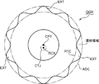
図1は、揺動歯車OGRの概略的な正面図である。図1を参照して、揺動歯車OGRの揺動回転が説明される。 FIG. 1 is a schematic front view of the swing gear OGR. With reference to FIG. 1, the swing rotation of the swing gear OGR will be described.
図1は、揺動歯車OGRの中心点CPTと、歯車装置(図示せず)の回転中心軸RCXと、を示す。揺動歯車OGRの中心点CPTは、歯車装置の回転中心軸RCXから離れている。歯車装置の外筒(図示せず)又はキャリア(図示せず)は、回転中心軸RCX周りに回転する。 FIG. 1 shows a center point CPT of the oscillating gear OGR and a rotation center axis RCX of a gear device (not shown). The center point CPT of the oscillating gear OGR is away from the rotation center axis RCX of the gear device. An outer cylinder (not shown) or a carrier (not shown) of the gear device rotates around the rotation center axis RCX.
図1は、回転中心軸RCXを中心とする円軌跡CTJを示す。揺動歯車OGRの揺動回転の間、中心点CPTは、円軌跡CTJに沿って移動する。 FIG. 1 shows a circular locus CTJ about the rotation center axis RCX. During the rocking rotation of the rocking gear OGR, the center point CPT moves along the circular locus CTJ.
図1は、揺動歯車OGRの歯底円RTCと、揺動歯車OGRの歯先円ADCと、を示す。以下の説明において、歯底円RTCと歯先円ADCとの間の領域は、「環状領域」と称される。揺動歯車OGRは、環状領域内で放射状に突出する複数の外歯EXTを含む。揺動歯車OGRの間、複数の外歯EXTは、外筒に形成された内歯(図示せず)に順次噛み合う。 FIG. 1 shows a root circle RTC of the oscillating gear OGR and a tooth tip circle ADC of the oscillating gear OGR. In the following description, a region between the root circle RTC and the tip circle ADC is referred to as an “annular region”. The oscillating gear OGR includes a plurality of external teeth EXT protruding radially within the annular region. During the swing gear OGR, the plurality of external teeth EXT sequentially mesh with internal teeth (not shown) formed on the outer cylinder.
図2は、揺動歯車OGRの回転変位を表す概念図である。図2を参照して、揺動歯車OGRの回転変位が説明される。 FIG. 2 is a conceptual diagram showing the rotational displacement of the oscillating gear OGR. With reference to FIG. 2, the rotational displacement of the rocking gear OGR will be described.
図2は、第1位置にある揺動歯車OGR(実線)と、第2位置にある揺動歯車OGR(点線)と、を示す。回転中心軸RCX周りの180°の回転位置差が、第1位置の揺動歯車OGRと第2位置の揺動歯車OGRとの間に存在する。 FIG. 2 shows the oscillating gear OGR (solid line) in the first position and the oscillating gear OGR (dotted line) in the second position. A rotational position difference of 180 ° around the rotation center axis RCX exists between the swing gear OGR at the first position and the swing gear OGR at the second position.
中心点CPTが位置的に変化しない通常の回転とは異なり、揺動回転下の揺動歯車OGRの中心点は、全方位的に変化する。したがって、図2に示される如く、環状領域も位置的に変化する。第2位置にある揺動歯車OGRの環状領域は、第1位置にある揺動歯車OGRの環状領域の下方に位置する。 Unlike normal rotation in which the center point CPT does not change in position, the center point of the oscillating gear OGR under oscillating rotation changes in all directions. Therefore, as shown in FIG. 2, the annular region also changes in position. The annular region of the oscillating gear OGR in the second position is located below the annular region of the oscillating gear OGR in the first position.
本発明者等は、軸受(図示せず)のレース(図示せず)の内周輪郭及び/又は外周輪郭が、環状領域の変動範囲内で規定されると、レースの角隅部が、揺動歯車OGRの外形輪郭に沿って規定される角隅部と点接触又は線接触し、レース及び/又は揺動歯車OGRの破損を生じやすいことを見出した。図2に示される如く、レースの内周輪郭及びレースの外周輪郭が、環状領域の変動範囲の外で規定されるならば、軸受のレースは、揺動歯車OGRに面接触することができる。この結果、レース及び/又は揺動歯車OGRの破損は生じにくくなる。 When the inner and / or outer contour of a race (not shown) of a bearing (not shown) is defined within the fluctuation range of the annular region, the inventors of the present invention will change the corner of the race. It has been found that the corners defined along the outer contour of the dynamic gear OGR are in point contact or line contact, and the race and / or the rocking gear OGR are likely to be damaged. As shown in FIG. 2, the bearing race can be in surface contact with the oscillating gear OGR if the inner and outer contours of the race are defined outside the variation range of the annular region. As a result, the race and / or the rocking gear OGR are hardly damaged.
以下の不等式によって表される条件が満たされるように、設計者は、レースの内径を決定してもよい。 The designer may determine the inner diameter of the race so that the condition represented by the following inequality is satisfied.
![]()
![]()
以下の不等式によって表される条件が満たされるように、設計者は、レースの外径を決定してもよい。 The designer may determine the outer diameter of the race so that the condition represented by the following inequality is satisfied.
![]()
![]()
<第2実施形態>
第1実施形態に関連して説明された設計原理は、様々な歯車装置に適用可能である。第2実施形態において、例示的な歯車装置が説明される。
Second Embodiment
The design principle described in relation to the first embodiment can be applied to various gear devices. In the second embodiment, an exemplary gear device is described.
図3A及び図3Bは、第2実施形態の歯車装置100を示す。図3Aは、歯車装置100の概略的な断面図である。図3Bは、図3Aに示されるA−A線に沿う歯車装置100の概略的な断面図である。図1乃至図3Bを参照して、歯車装置100が説明される。
3A and 3B show the
歯車装置100は、外筒200と、キャリア300(図3Aを参照)と、歯車部400(図3Aを参照)と、3つの駆動機構500(図3Aは、3つの駆動機構500のうち1つを示す)と、2つの主軸受600(図3Aを参照)と、を備える。第1実施形態の揺動歯車OGRの揺動回転に関する説明は、歯車部400の運動に援用される。
The
外筒200は、略円筒状の外殻筒210と、複数の内歯ピン220と、を含む。外殻筒210は、キャリア300、歯車部400及び駆動機構500が収容される円筒状の内部空間を規定する。内歯ピン220は、外殻筒210の内周面に沿って環状に並べられ、内歯環を形成する。本実施形態において、複数の内歯は、内歯ピン220によって例示される。
The
2つの主軸受600は、外筒200と、外筒200によって取り囲まれたキャリア300との間に配置される。2つの主軸受600それぞれは、外筒200とキャリア300との間の相対的な回転運動を可能にする。第1実施形態に関連して説明された軸受の設計原理は、2つの主軸受600それぞれに適用される。
The two
図3A及び図3Bそれぞれは、図1を参照して説明された回転中心軸RCXを示す。内歯ピン220それぞれは、回転中心軸RCXの延出方向に延びる円柱状の部材である。内歯ピン220それぞれは、外殻筒210の内壁に形成された溝部に嵌入される。したがって、内歯ピン220それぞれは、外殻筒210によって適切に保持される。
3A and 3B each show the rotation center axis RCX described with reference to FIG. Each
複数の内歯ピン220は、回転中心軸RCX周りに略一定間隔で配置される。内歯ピン220それぞれの半周面は、外殻筒210の内壁から回転中心軸RCXに向けて突出する。したがって、複数の内歯ピン220は、歯車部400と噛み合う内歯として機能する。
The plurality of internal teeth pins 220 are arranged at substantially constant intervals around the rotation center axis RCX. The half circumferential surface of each
キャリア300は、基部310(図3Aを参照)と、端板部320(図3Aを参照)と、を含む。キャリア300は、全体的に、円筒状である。上述の如く、キャリア300は、外筒200に対して相対的に回転することができる。キャリア300が、固定されるならば、外筒200は、回転中心軸RCX周りに回転する。外筒200が固定されるならば、キャリア300は、回転中心軸RCX周りに回転する。
The
基部310は、基板部311(図3Aを参照)と、9つのシャフト部312(図3Bを参照)と、を含む。9つのシャフト部312それぞれは、基板部311から端板部320に向けて延びる。端板部320は、9つのシャフト部312それぞれの先端面に接続される。端板部320は、リーマボルト、位置決めピンや他の適切な固定技術によって、9つのシャフト部312それぞれの先端面に接続されてもよい。本実施形態の原理は、端板部320と9つのシャフト部312それぞれとの間の特定の接続技術に限定されない。
The
歯車部400は、基板部311と端板部320との間に配置される。9つのシャフト部312は、歯車部400を貫通し、端板部320に接続される。
The
歯車部400は、第1歯車410(図3A参照)と、第2歯車420(図3A参照)と、を含む。第1歯車410は、基板部311と第2歯車420との間に配置される。第2歯車420は、端板部320と第1歯車410との間に配置される。
The
第1歯車410及び第2歯車420は、共通の設計図面に基づいて形成されてもよい。第1歯車410及び第2歯車420ぞれぞれは、図1を参照して説明された揺動歯車OGRに対応する。図3Aに示される第1歯車410は、図2を参照して説明された第1位置にある揺動歯車OGRに対応付けられてもよい。図3Aに示される第2歯車420は、図2を参照して説明された第2位置にある揺動歯車OGRに対応付けられてもよい。
The
第1歯車410及び第2歯車420は、内歯ピン220に噛み合いながら、外殻筒210内を周回移動する。この間、第1実施形態に関連して説明された如く、第1歯車410及び第2歯車420の中心は、回転中心軸RCX周りを周回することとなる。
The
3つの駆動機構500それぞれは、伝達歯車510(図3Aを参照)と、クランク軸520と、2つのジャーナル軸受530と、2つのクランク軸受540と、を含む。伝達歯車510は、モータといった適切な駆動源(図示せず)によって生成された駆動力を受け取る。伝達歯車510は、駆動源に直接的に接続されてもよい。代替的に、伝達歯車510は、駆動力を伝達することができる他の機構を通じて、駆動力を受け取ってもよい(間接的な接続)。本実施形態の原理は、伝達歯車510と駆動源との間の特定の接続構造に限定されない。
Each of the three
クランク軸520は、第1ジャーナル521(図3Aを参照)と、第2ジャーナル522(図3Aを参照)と、第1偏心部523(図3Aを参照)と、第2偏心部524(図3Aを参照)と、を含む。第1ジャーナル521は、キャリア300の基板部311によって取り囲まれる。第2ジャーナル522は、キャリア300の端板部320によって取り囲まれる。2つのジャーナル軸受530のうち一方は、第1ジャーナル521と基板部311との間に配置される。2つのジャーナル軸受530のうち他方は、第2ジャーナル522と端板部320との間に配置される。加えて、上述の伝達歯車510は、第2ジャーナル522に取り付けられる。
The
第1偏心部523は、第1ジャーナル521と第2偏心部524との間に位置する。第2偏心部524は、第2ジャーナル522と第1偏心部523との間に位置する。2つのクランク軸受540のうち一方は、第1偏心部523と第1歯車410との間に配置される。2つのクランク軸受540のうち他方は、第2偏心部524と第2歯車420との間に配置される。
The first
第1ジャーナル521は、第2ジャーナル522と同軸であり、共通の回転軸周りで回転する。第1偏心部523及び第2偏心部524それぞれは、円柱状に形成され、第1ジャーナル521及び第2ジャーナル522の回転軸から偏心している。第1歯車410と第2歯車420との間の周回位相差は、第1偏心部523及び第2偏心部524によって決定される。
The
伝達歯車510が回転すると、クランク軸520は、回転する。この結果、第1偏心部523及び第2偏心部524は、偏心回転する。この間、クランク軸受540を介して第1偏心部523に接続された第1歯車410は、複数の内歯ピン220と噛み合いながら、外筒200内で周回移動することができる。同様に、クランク軸受540を介して第2偏心部524に接続された第2歯車420は、複数の内歯ピン220と噛み合いながら、外筒200内で周回移動することができる。この結果、第1歯車410及び第2歯車420それぞれは、外筒200内で、第1実施形態に関連して説明された揺動回転を行うことができる。
When the
外筒200が固定されているならば、第1歯車410及び第2歯車420の揺動回転の間、キャリア300は、外筒200内で回転する。キャリア300が固定されているならば、第1歯車410及び第2歯車420の揺動回転の間、外筒200は、キャリア300の外側で回転する。
If the
図4は、主軸受600周りの歯車装置100の概略的な拡大断面図である。図1、図3A乃至図4を参照して、歯車装置100が更に説明される。
FIG. 4 is a schematic enlarged cross-sectional view of the
第1歯車410は、複数の外歯411(図3Bを参照)を含む。第1歯車410の揺動回転の間、複数の外歯411は、内歯環(環状の配列された複数の内歯ピン220)に順次噛み合う。同様に、第2歯車420は、複数の外歯421を含む。第2歯車420の揺動回転の間、複数の外歯421は、内歯環に順次噛み合う。
The
複数の外歯411が形成された領域は、図1を参照して説明された環状領域に相当する。同様に、複数の外歯421が形成された領域も、図1を参照して説明された環状領域に相当する。
The region where the plurality of
図4に示される如く、2つの主軸受600それぞれは、インナーレース610と、アウターレース620と、複数のボール630(図4は、2つの主軸受け600それぞれに対して1つのボール630を示す)と、を含む。キャリア300は、インナーレース610に嵌入される。アウターレース620は、インナーレース610を取り巻き、外筒200を支持する。複数のボール630は、インナーレース610とアウターレース620との間で環状に配列される。第1実施形態に関連して説明されたレースの設計原理は、インナーレース610に適用される。本実施形態において、複数の転動体は、複数のボール630によって例示される。
As shown in FIG. 4, each of the two
図4に示される如く、インナーレース610は、環状領域に対向する環状の対向面611を含む。歯車装置100を設計する設計者は、対向面611の内径を、第1実施形態に関連して説明された「数1」に示される不等式によって規定される関係が充足されるように設定することができる。同様に、設計者は、対向面611の外径を、第1実施形態に関連して説明された「数2」に示される不等式によって規定される関係が充足されるように設定することができる。したがって、対向面611は、第1歯車410及び第2歯車420の揺動回転の間、環状領域全体に重なることとなる。
As shown in FIG. 4, the
図4に示される如く、インナーレース610と協働して複数のボール630を挟むアウターレース620は、外筒200に当接し、且つ、対向面611に略面一の当接面621を含む。当接面621は、対向面611に沿って環状に延び、対向面611を取り巻く。当接面621の内径と外径との間の差は、対向面611の内径と外径との間の差よりも小さい値に設定されてもよい。この結果、設計者は、外筒200の内径に小さな値を与えることができる。本実施形態において、第1レース及び第2レースのうち一方は、インナーレース610によって例示される。第1レース及び第2レースのうち他方は、アウターレース620によって例示される。
As shown in FIG. 4, the
<第3実施形態>
第1実施形態に関連して説明された設計原理は、軸受のアウターレースに適用されてもよい。第3実施形態において、厚いアウターレースを有する軸受を備える例示的な歯車装置が説明される。
<Third Embodiment>
The design principle described in connection with the first embodiment may be applied to the outer race of the bearing. In a third embodiment, an exemplary gear device is described that includes a bearing having a thick outer race.
図5は、第3実施形態の歯車装置100Aの拡大部分断面図である。第2実施形態の説明は、第2実施形態と同一の符号が付された要素に対して援用される。図5を参照して、歯車装置100Aが説明される。
FIG. 5 is an enlarged partial cross-sectional view of the
第2実施形態と同様に、歯車装置100Aは、第1歯車410と、第2歯車420と、を備える。第1歯車410及び第2歯車420の揺動回転は、第2実施形態と同様の駆動構造によって引き起こされる。第2実施形態の説明は、第1歯車410、第2歯車420及びこれらを駆動する駆動構造に援用される。
Similar to the second embodiment, the
第2実施形態と同様に、歯車装置100Aは、外筒200を更に備える。第2実施形態の説明は、外筒200に援用される。
Similar to the second embodiment, the
歯車装置100Aは、2つの主軸受600Aと、キャリア300Aと、を更に備える。2つの主軸受600Aそれぞれは、アウターレース620Aと、複数のボール630A(図4は、2つの主軸受600Aそれぞれに対して1つのボール630Aを示す)と、を含む。複数のボール630Aは、キャリア300Aの外周面を取り囲むように環状に配列される。第2実施形態とは異なり、複数のボール630Aは、キャリア300Aに直接的に接触する。キャリア300Aの外周面は、複数のボール630Aの転動を許容するように加工される。第2実施形態の説明は、キャリア300Aの他の構造的特徴に援用される。
The
アウターレース620Aは、環状領域に対向する環状の対向面622を含む。歯車装置100Aを設計する設計者は、対向面622の内径を、第1実施形態に関連して説明された「数1」に示される不等式によって規定される関係が充足されるように設定することができる。同様に、設計者は、対向面622の外径を、第1実施形態に関連して説明された「数2」に示される不等式によって規定される関係が充足されるように設定することができる。したがって、対向面622は、第1歯車410及び第2歯車420の揺動回転の間、環状領域全体に重なることとなる。アウターレース620Aは、第1実施形態に関連して説明されたレースに対応する。
The
上述の様々な実施形態に関連して説明された設計原理は、様々な歯車装置に適用可能である。上述の様々な実施形態のうち1つに関連して説明された様々な特徴のうち一部が、他のもう1つの実施形態に関連して説明された歯車装置に適用されてもよい。 The design principles described in connection with the various embodiments described above are applicable to various gear devices. Some of the various features described in connection with one of the various embodiments described above may be applied to the gearing described in connection with another embodiment.
上述の実施形態の原理は、揺動回転する歯車を有する歯車装置に好適に利用される。 The principle of the above-described embodiment is suitably used for a gear device having a gear that rotates and rotates.
100,100A・・・・・・・・・・・・・・・・・・・・歯車装置
200・・・・・・・・・・・・・・・・・・・・・・・・・外筒
220・・・・・・・・・・・・・・・・・・・・・・・・・内歯ピン
300,300A・・・・・・・・・・・・・・・・・・・・キャリア
410・・・・・・・・・・・・・・・・・・・・・・・・・第1歯車
411・・・・・・・・・・・・・・・・・・・・・・・・・外歯
420・・・・・・・・・・・・・・・・・・・・・・・・・第2歯車
421・・・・・・・・・・・・・・・・・・・・・・・・・外歯
600,600A・・・・・・・・・・・・・・・・・・・・主軸受
610・・・・・・・・・・・・・・・・・・・・・・・・・インナーレース
611・・・・・・・・・・・・・・・・・・・・・・・・・対向面
620,620A・・・・・・・・・・・・・・・・・・・・アウターレース
622・・・・・・・・・・・・・・・・・・・・・・・・・対向面
630,630A・・・・・・・・・・・・・・・・・・・・ボール
ADC・・・・・・・・・・・・・・・・・・・・・・・・・歯先円
CTJ・・・・・・・・・・・・・・・・・・・・・・・・・円軌跡
EXT・・・・・・・・・・・・・・・・・・・・・・・・・外歯
OGR・・・・・・・・・・・・・・・・・・・・・・・・・揺動歯車
RCX・・・・・・・・・・・・・・・・・・・・・・・・・回転中心軸
RTC・・・・・・・・・・・・・・・・・・・・・・・・・歯底円
100, 100A ...
Claims (4)
前記外筒によって囲まれたキャリアと、
前記外筒と前記キャリアとの間の相対回転を許容する軸受と、
前記外筒内で揺動回転し、前記相対回転を生じさせる揺動歯車と、を備え、
前記揺動歯車は、揺動回転の間、前記内歯環と順次噛み合う複数の外歯と、前記揺動歯車の歯底円と前記揺動歯車の歯先円との間の領域として規定される環状領域と、を含み、
前記軸受は、前記環状領域に対向する環状の対向面を有するレースを含み、
前記対向面は、前記揺動回転の間、前記環状領域全体に重なり、
前記軸受は、環状に配列された複数の転動体を含み、
前記レースは、前記複数の転動体によって囲まれるインナーレースである
歯車装置。 An outer cylinder having an inner tooth ring including a plurality of inner teeth;
A carrier surrounded by the outer cylinder;
A bearing that allows relative rotation between the outer cylinder and the carrier;
A rocking gear that rocks and rotates in the outer cylinder and generates the relative rotation,
The swing gear is defined as a region between a plurality of external teeth that sequentially mesh with the inner tooth ring during swing rotation, and a root circle of the swing gear and a tip circle of the swing gear. An annular region,
The bearing includes a race having an annular facing surface facing the annular region;
The facing surface, between the pivot rotation, Ri Do heavy throughout the annular region,
The bearing includes a plurality of rolling elements arranged in an annular shape,
The race, Oh Ru gear with inner race surrounded by said plurality of rolling elements.
前記アウターレースは、前記対向面に沿って延びる環状の沿縁面を含み、
前記対向面は、前記沿縁面よりも幅広である
請求項1に記載の歯車装置。 Before SL bearing pre SL in cooperation with the inner race comprises an outer race that sandwich a plurality of rolling elements,
Before Symbol outer race includes沿縁surface of the annular extending along the opposed surface,
The facing surface is wider than the edge surface.
The gear device according to claim 1 .
前記対向面の内径は、前記歯底円の直径と前記円軌跡の直径との差以下である
請求項1又は2に記載の歯車装置。 The center of the oscillating gear rotates around the rotation center axis of the outer cylinder or the carrier while drawing a circular locus,
The gear device according to claim 1, wherein an inner diameter of the facing surface is equal to or less than a difference between a diameter of the root circle and a diameter of the circular locus.
請求項3に記載の歯車装置。 The gear device according to claim 3 , wherein an outer diameter of the facing surface is equal to or greater than a sum of a diameter of the tooth tip circle and the diameter of the circular locus.
Priority Applications (2)
| Application Number | Priority Date | Filing Date | Title |
|---|---|---|---|
| JP2015133651A JP6573788B2 (en) | 2015-07-02 | 2015-07-02 | Gear device |
| CN201620690913.5U CN205780628U (en) | 2015-07-02 | 2016-07-01 | Geared system |
Applications Claiming Priority (1)
| Application Number | Priority Date | Filing Date | Title |
|---|---|---|---|
| JP2015133651A JP6573788B2 (en) | 2015-07-02 | 2015-07-02 | Gear device |
Publications (2)
| Publication Number | Publication Date |
|---|---|
| JP2017015196A JP2017015196A (en) | 2017-01-19 |
| JP6573788B2 true JP6573788B2 (en) | 2019-09-11 |
Family
ID=57829026
Family Applications (1)
| Application Number | Title | Priority Date | Filing Date |
|---|---|---|---|
| JP2015133651A Active JP6573788B2 (en) | 2015-07-02 | 2015-07-02 | Gear device |
Country Status (2)
| Country | Link |
|---|---|
| JP (1) | JP6573788B2 (en) |
| CN (1) | CN205780628U (en) |
Families Citing this family (1)
| Publication number | Priority date | Publication date | Assignee | Title |
|---|---|---|---|---|
| CN111120789B (en) * | 2018-10-31 | 2022-08-09 | 佳能株式会社 | Rotating mechanism and equipment comprising same |
-
2015
- 2015-07-02 JP JP2015133651A patent/JP6573788B2/en active Active
-
2016
- 2016-07-01 CN CN201620690913.5U patent/CN205780628U/en active Active
Also Published As
| Publication number | Publication date |
|---|---|
| CN205780628U (en) | 2016-12-07 |
| JP2017015196A (en) | 2017-01-19 |
Similar Documents
| Publication | Publication Date | Title |
|---|---|---|
| JP5466739B2 (en) | Eccentric oscillating gear unit | |
| JP2005226827A (en) | Eccentrically swinging gear device | |
| JP2010156430A (en) | Deceleration device | |
| JP2019090477A (en) | Eccentric oscillation type gear device | |
| JP2016121719A (en) | Ball bearing for harmonic speed reducer | |
| JP2023184669A (en) | gear unit | |
| JP2017128302A (en) | Steering device | |
| JP2017044319A (en) | Eccentric oscillation type gear device and industrial robot | |
| JP2018091427A (en) | Reduction gear | |
| JP2014092249A (en) | Gear device | |
| JP6278762B2 (en) | Eccentric rocking gear device | |
| JP6573788B2 (en) | Gear device | |
| TWI763689B (en) | gear unit | |
| US8651992B2 (en) | Speed reducer, robot hand and robot | |
| JP2013100911A (en) | Flexible meshing type gear device and method for determining tooth profile of flexible meshing type gear device | |
| JP2011052785A (en) | Planetary reduction gear | |
| JP6144996B2 (en) | Eccentric oscillation type speed reducer | |
| TWI698599B (en) | Eccentric oscillating gear device and manufacturing method thereof | |
| JP6184546B2 (en) | Eccentric oscillating gear unit | |
| JP6372752B2 (en) | Traction power transmission device | |
| JPWO2020004005A1 (en) | Decelerator | |
| JP6757149B2 (en) | Gear device | |
| JP6446101B2 (en) | Eccentric oscillating gear unit | |
| JP2011021659A (en) | Eccentric reduction gear | |
| JP6624938B2 (en) | Gear device and output gear plate |
Legal Events
| Date | Code | Title | Description |
|---|---|---|---|
| A621 | Written request for application examination |
Free format text: JAPANESE INTERMEDIATE CODE: A621 Effective date: 20180612 |
|
| A977 | Report on retrieval |
Free format text: JAPANESE INTERMEDIATE CODE: A971007 Effective date: 20190410 |
|
| A131 | Notification of reasons for refusal |
Free format text: JAPANESE INTERMEDIATE CODE: A131 Effective date: 20190423 |
|
| A521 | Request for written amendment filed |
Free format text: JAPANESE INTERMEDIATE CODE: A523 Effective date: 20190621 |
|
| TRDD | Decision of grant or rejection written | ||
| A01 | Written decision to grant a patent or to grant a registration (utility model) |
Free format text: JAPANESE INTERMEDIATE CODE: A01 Effective date: 20190806 |
|
| A61 | First payment of annual fees (during grant procedure) |
Free format text: JAPANESE INTERMEDIATE CODE: A61 Effective date: 20190814 |
|
| R150 | Certificate of patent or registration of utility model |
Ref document number: 6573788 Country of ref document: JP Free format text: JAPANESE INTERMEDIATE CODE: R150 |
|
| R250 | Receipt of annual fees |
Free format text: JAPANESE INTERMEDIATE CODE: R250 |
|
| R250 | Receipt of annual fees |
Free format text: JAPANESE INTERMEDIATE CODE: R250 |