JP6941733B2 - A support frame for a pellicle, a method for manufacturing a pellicle and a support frame for a pellicle, and an exposure plate and an exposure apparatus using the pellicle. - Google Patents

A support frame for a pellicle, a method for manufacturing a pellicle and a support frame for a pellicle, and an exposure plate and an exposure apparatus using the pellicle. Download PDF

Info

Publication number
JP6941733B2
JP6941733B2 JP2020525616A JP2020525616A JP6941733B2 JP 6941733 B2 JP6941733 B2 JP 6941733B2 JP 2020525616 A JP2020525616 A JP 2020525616A JP 2020525616 A JP2020525616 A JP 2020525616A JP 6941733 B2 JP6941733 B2 JP 6941733B2
Authority
JP
Japan
Prior art keywords
support frame
pellicle
thin plate
filter
engaging portion
Prior art date
Legal status (The legal status is an assumption and is not a legal conclusion. Google has not performed a legal analysis and makes no representation as to the accuracy of the status listed.)
Active
Application number
JP2020525616A
Other languages
Japanese (ja)
Other versions
JPWO2019240166A1 (en
Inventor
彰 石川
彰 石川
敦 大久保
敦 大久保
陽介 小野
陽介 小野
高村 一夫
一夫 高村
Current Assignee (The listed assignees may be inaccurate. Google has not performed a legal analysis and makes no representation or warranty as to the accuracy of the list.)
Mitsui Chemicals Inc
Original Assignee
Mitsui Chemicals Inc
Priority date (The priority date is an assumption and is not a legal conclusion. Google has not performed a legal analysis and makes no representation as to the accuracy of the date listed.)
Filing date
Publication date
Application filed by Mitsui Chemicals Inc filed Critical Mitsui Chemicals Inc
Publication of JPWO2019240166A1 publication Critical patent/JPWO2019240166A1/en
Application granted granted Critical
Publication of JP6941733B2 publication Critical patent/JP6941733B2/en
Active legal-status Critical Current
Anticipated expiration legal-status Critical

Links

Images

Classifications

    • GPHYSICS
    • G03PHOTOGRAPHY; CINEMATOGRAPHY; ANALOGOUS TECHNIQUES USING WAVES OTHER THAN OPTICAL WAVES; ELECTROGRAPHY; HOLOGRAPHY
    • G03FPHOTOMECHANICAL PRODUCTION OF TEXTURED OR PATTERNED SURFACES, e.g. FOR PRINTING, FOR PROCESSING OF SEMICONDUCTOR DEVICES; MATERIALS THEREFOR; ORIGINALS THEREFOR; APPARATUS SPECIALLY ADAPTED THEREFOR
    • G03F1/00Originals for photomechanical production of textured or patterned surfaces, e.g., masks, photo-masks, reticles; Mask blanks or pellicles therefor; Containers specially adapted therefor; Preparation thereof
    • G03F1/62Pellicles, e.g. pellicle assemblies, e.g. having membrane on support frame; Preparation thereof
    • G03F1/64Pellicles, e.g. pellicle assemblies, e.g. having membrane on support frame; Preparation thereof characterised by the frames, e.g. structure or material, including bonding means therefor
    • GPHYSICS
    • G03PHOTOGRAPHY; CINEMATOGRAPHY; ANALOGOUS TECHNIQUES USING WAVES OTHER THAN OPTICAL WAVES; ELECTROGRAPHY; HOLOGRAPHY
    • G03FPHOTOMECHANICAL PRODUCTION OF TEXTURED OR PATTERNED SURFACES, e.g. FOR PRINTING, FOR PROCESSING OF SEMICONDUCTOR DEVICES; MATERIALS THEREFOR; ORIGINALS THEREFOR; APPARATUS SPECIALLY ADAPTED THEREFOR
    • G03F1/00Originals for photomechanical production of textured or patterned surfaces, e.g., masks, photo-masks, reticles; Mask blanks or pellicles therefor; Containers specially adapted therefor; Preparation thereof
    • G03F1/22Masks or mask blanks for imaging by radiation of 100nm or shorter wavelength, e.g. X-ray masks, extreme ultraviolet [EUV] masks; Preparation thereof
    • GPHYSICS
    • G03PHOTOGRAPHY; CINEMATOGRAPHY; ANALOGOUS TECHNIQUES USING WAVES OTHER THAN OPTICAL WAVES; ELECTROGRAPHY; HOLOGRAPHY
    • G03FPHOTOMECHANICAL PRODUCTION OF TEXTURED OR PATTERNED SURFACES, e.g. FOR PRINTING, FOR PROCESSING OF SEMICONDUCTOR DEVICES; MATERIALS THEREFOR; ORIGINALS THEREFOR; APPARATUS SPECIALLY ADAPTED THEREFOR
    • G03F7/00Photomechanical, e.g. photolithographic, production of textured or patterned surfaces, e.g. printing surfaces; Materials therefor, e.g. comprising photoresists; Apparatus specially adapted therefor
    • G03F7/70Microphotolithographic exposure; Apparatus therefor
    • G03F7/708Construction of apparatus, e.g. environment aspects, hygiene aspects or materials
    • G03F7/70983Optical system protection, e.g. pellicles or removable covers for protection of mask

Landscapes

  • Physics & Mathematics (AREA)
  • General Physics & Mathematics (AREA)
  • Health & Medical Sciences (AREA)
  • Engineering & Computer Science (AREA)
  • Environmental & Geological Engineering (AREA)
  • Epidemiology (AREA)
  • Public Health (AREA)
  • Preparing Plates And Mask In Photomechanical Process (AREA)
  • Exposure And Positioning Against Photoresist Photosensitive Materials (AREA)

Description

本発明は、半導体デバイス等をリソグラフィ技術により製造する際に使用するフォトマスクまたはレチクル(以下、これらを総称して「フォトマスク」ともいう)及び、塵埃が付着することを防ぐフォトマスク用防塵カバーであるペリクル等に関する。特に、本発明は、極端紫外光(Extreme Ultraviolet:EUV)リソグラフィ用のペリクル用支持枠、ペリクル及びペリクル用支持枠の製造方法、並びにペリクルを用いた露光原版及び露光装置に関する。 The present invention relates to a photomask or reticle (hereinafter, collectively referred to as "photomask") used when manufacturing a semiconductor device or the like by a lithography technique, and a dustproof cover for a photomask that prevents dust from adhering to the photomask or reticle. Regarding pellicle etc. In particular, the present invention relates to a pellicle support frame for extreme ultraviolet light (EUV) lithography, a method for manufacturing a pellicle and a pellicle support frame, and an exposure master plate and an exposure apparatus using the pellicle.

半導体素子は、リソグラフィと称される工程を経て製造される。リソグラフィでは、スキャナやステッパと呼ばれる露光装置を用いて、回路パターンが描画されたマスクに露光光を照射して、フォトレジストが塗布された半導体ウェハに回路パターンを転写する。現在までに、リソグラフィの波長は短波長化が進み、次世代のリソグラフィ技術として、EUVリソグラフィの開発が進められている。EUV光は、軟X線領域又は真空紫外線領域の波長の光を指し、13.5nm±0.3nm程度の光線を指す。EUV光は、あらゆる物質に対して吸収されやすく、したがって、EUVリソグラフィでは、露光装置内を真空にして露光する必要がある。EUV光は、あらゆる物質に対して吸収されやすいため、ペリクルに配置するペリクル膜も従来にないナノメートルオーダーの膜である必要がある。 Semiconductor devices are manufactured through a process called lithography. In lithography, an exposure device called a scanner or a stepper is used to irradiate a mask on which a circuit pattern is drawn with exposure light to transfer the circuit pattern to a semiconductor wafer coated with a photoresist. To date, the wavelength of lithography has been shortened, and EUV lithography is being developed as a next-generation lithography technology. EUV light refers to light having a wavelength in the soft X-ray region or vacuum ultraviolet region, and refers to light rays having a wavelength of about 13.5 nm ± 0.3 nm. EUV light is easily absorbed by all substances. Therefore, in EUV lithography, it is necessary to evacuate the inside of the exposure apparatus for exposure. Since EUV light is easily absorbed by all substances, the pellicle film placed on the pellicle also needs to be a film on the order of nanometers, which has never existed before.

露光装置内を真空にして行うEUVリソグラフィにおいては、当初、フォトマスクへのペリクルの装着は必須ではないと考えられていたため、現在開発されているEUV露光装置には、フォトマスクへペリクルを装着するための空間が3.0mm程度しか存在していない。しかし、5mm以上の高さを有する従来のペリクルを装着するための空間を露光装置内に確保するには、光学系の設計変更が必要となり、EUVリソグラフィの開発に遅延をきたすこととなる。したがって、従来のペリクルの半分以下程度の高さとするペリクルを新たに設計する必要がある。 Since it was initially thought that attaching a pellicle to a photomask was not essential for EUV lithography in which the inside of the exposure apparatus was evacuated, the EUV exposure apparatus currently being developed is equipped with a pellicle on a photomask. There is only about 3.0 mm of space for this. However, in order to secure a space in the exposure apparatus for mounting a conventional pellicle having a height of 5 mm or more, it is necessary to change the design of the optical system, which delays the development of EUV lithography. Therefore, it is necessary to newly design a pellicle that is less than half the height of the conventional pellicle.

露光装置内を真空にすると、フォトマスクとペリクルによって形成される閉空間(ペリクルの内側)と、その外側との圧力差が生じ、ペリクル膜がたるんだり、或いは膨らんだりしうる。この解決手段として、通気孔を設けることが考えられる。しかし、ペリクルの設置空間が大幅に制限されるため、ナノメートルオーダーのペリクル膜の損傷を防ぐには、ペリクルの枠体に配置した通気孔を介した十分な通気を確保する必要がある。通気孔にはペリクルの内側への異物混入を防ぐためその途中にフィルタを配置する必要があるが、ペリクルの設置空間が大幅に制限され、しかも枠体に許容される高さも大幅に制限されるため、枠体へのフィルタの配置も従来にない設計が要求される。 When the inside of the exposure apparatus is evacuated, a pressure difference is generated between the closed space formed by the photomask and the pellicle (inside the pellicle) and the outside thereof, and the pellicle film may sag or swell. As a solution to this, it is conceivable to provide ventilation holes. However, since the installation space of the pellicle is significantly limited, it is necessary to ensure sufficient ventilation through the ventilation holes arranged in the frame of the pellicle in order to prevent damage to the pellicle membrane on the order of nanometers. It is necessary to place a filter in the ventilation hole in the middle to prevent foreign matter from entering the inside of the pellicle, but the installation space of the pellicle is greatly limited, and the height allowed for the frame is also greatly limited. Therefore, an unprecedented design is required for the arrangement of the filter on the frame.

例えば、特許文献1には、耐熱性や通気スピード(減圧時間)、異物捕集効率の観点から、金属製又はセラミックス製であるとともに、ペリクルフレームと溶接によって連続的に一体化されたフィルタで通気孔を覆ったEUV露光用ペリクルが記載されている。 For example, in Patent Document 1, from the viewpoint of heat resistance, ventilation speed (decompression time), and foreign matter collection efficiency, a filter made of metal or ceramics and continuously integrated with a pellicle frame by welding is used. A pellicle for EUV exposure covering the pores is described.

特開2017−116697号公報Japanese Unexamined Patent Publication No. 2017-116697

通気孔を覆うフィルタは、EUV光の露光により劣化するため、交換する必要がある。ペリクルフレームと一体化されたフィルタを交換するのは容易ではなく、簡便にフィルタを交換可能なペリクルが望まれる。 The filter covering the vents deteriorates due to exposure to EUV light and needs to be replaced. It is not easy to replace the filter integrated with the pellicle frame, and a pellicle in which the filter can be easily replaced is desired.

本発明は、上述の問題を解決するもので、通気孔に容易に着脱可能なフィルタが設けられ、極端紫外光リソグラフィ用のペリクル膜を設けることができる支持枠、当該支持枠に極端紫外光リソグラフィ用のペリクル膜を設けたペリクル、及び支持枠の製造方法、並びにこれらの支持枠を用いた露光原版及び露光装置を提供することを目的とする。 The present invention solves the above-mentioned problems, and is a support frame in which a filter that can be easily attached and detached is provided in a ventilation hole and a pellicle film for extreme ultraviolet light lithography can be provided, and extreme ultraviolet light lithography is provided on the support frame. It is an object of the present invention to provide a pellicle provided with a pellicle film for use, a method for manufacturing a support frame, and an exposure plate and an exposure apparatus using these support frames.

本発明の一実施形態に係るペリクル用支持枠は、第1の支持枠部と、第2の支持枠部と、フィルタと、を有するペリクル用支持枠であって、前記フィルタは平板状の枠形状を有し、前記第1の支持枠部と前記第2の支持枠部とに挟持され、前記第1の支持枠部は、平板状の枠形状を有する第1の本体部と、前記第1の本体部から前記ペリクル用支持枠の厚み方向に突出した第1の係合部と、を有し、前記第2の支持枠部は、平板状の枠形状を有する第2の本体部と、前記第2の本体部の前記ペリクル用支持枠の厚み方向に設けられた凹部に配置され、前記第1の係合部と係合する第2の係合部と、を有する。 The support frame for a pellicle according to an embodiment of the present invention is a support frame for a pellicle having a first support frame portion, a second support frame portion, and a filter, and the filter is a flat plate-shaped frame. The first support frame portion has a shape and is sandwiched between the first support frame portion and the second support frame portion, and the first support frame portion includes a first main body portion having a flat plate-like frame shape and the first main body portion. It has a first engaging portion protruding from the main body portion of 1 in the thickness direction of the pellicle support frame, and the second support frame portion has a second main body portion having a flat plate-like frame shape. The second main body has a second engaging portion that is arranged in a recess provided in the thickness direction of the pellicle support frame and engages with the first engaging portion.

本発明の一実施形態において、前記第1の係合部は、前記第1の本体部から前記ペリクル用支持枠の厚み方向に延在する第1の延在部と、前記第1の延在部の前記第1の本体部とは反対側の端部から前記ペリクル用支持枠の厚み方向と交差する方向に延在する第2の延在部と、を有し、前記第2の係合部は、前記第1の支持枠部側に位置する前記第2の支持枠部の第1の面から前記ペリクル用支持枠の厚み方向に延在する第1の溝部と、前記第1の溝部の底部から前記ペリクル用支持枠の厚み方向と交差する方向に延在する第2の溝部とを有し、前記第2の延在部の少なくとも一部は、前記第2の溝部に収容されてもよい。 In one embodiment of the present invention, the first engaging portion includes a first extending portion extending from the first main body portion in the thickness direction of the pellicle support frame, and the first extending portion. The second engaging portion has a second extending portion extending in a direction intersecting the thickness direction of the pellicle support frame from an end portion of the portion opposite to the first main body portion. The portions are a first groove portion extending in the thickness direction of the pellicle support frame from the first surface of the second support frame portion located on the first support frame portion side, and the first groove portion. It has a second groove extending from the bottom of the pellicle in a direction intersecting the thickness direction of the pellicle support frame, and at least a part of the second extending portion is housed in the second groove. May be good.

本発明の一実施形態において、前記フィルタは、前記第1の係合部及び前記第2の係合部に対応する位置に開口を有し、前記第1の係合部は、前記開口を貫通して、前記第2の係合部と係合してもよい。 In one embodiment of the present invention, the filter has an opening at a position corresponding to the first engaging portion and the second engaging portion, and the first engaging portion penetrates the opening. Then, it may be engaged with the second engaging portion.

本発明の一実施形態において、前記第2の係合部は、前記第2の溝部の底部から前記第1の面の方向に離間して配置される固定具を有し、前記第2の溝部は、前記第1の溝部の底部と前記固定具とにより構成されてもよい。 In one embodiment of the present invention, the second engaging portion has a fixture that is disposed apart from the bottom of the second groove portion in the direction of the first surface, and the second groove portion. May be composed of the bottom portion of the first groove portion and the fixture.

本発明の一実施形態において、前記固定具は、治具と係合可能な第3の係合部を有していてもよい。 In one embodiment of the invention, the fixture may have a third engaging portion that can engage the jig.

本発明の一実施形態において、前記ペリクル用支持枠の内縁部と外縁部とを接続し、前記フィルタが配置された通気孔をさらに有してもよい。 In one embodiment of the present invention, the inner edge portion and the outer edge portion of the support frame for the pellicle may be connected to each other, and a vent hole in which the filter is arranged may be further provided.

本発明の一実施形態において、前記通気孔は、前記フィルタが配置され、前記ペリクル用支持枠の厚み方向と略平行な第1の方向に延びる第1の孔と、前記第1の孔の第1の端部に接続し、前記第1の方向と交差する第2の方向に延伸し、前記内縁部又は前記外縁部に開口を有する第2の孔と、を有してもよい。 In one embodiment of the present invention, the ventilation holes include a first hole in which the filter is arranged and extending in a first direction substantially parallel to the thickness direction of the pellicle support frame, and a first hole of the first hole. It may have a second hole that connects to the end of 1 and extends in a second direction that intersects the first direction and has an opening in the inner or outer edge.

本発明の一実施形態において、前記通気孔は、前記第1の孔の第2の端部に接続し、前記ペリクル用支持枠の厚み方向と交差する方向に設けられた第3の孔をさらに有してもよい。 In one embodiment of the present invention, the vent is connected to a second end of the first hole, and a third hole provided in a direction intersecting the thickness direction of the pellicle support frame is further provided. You may have.

本発明の一実施形態において、複数の前記第1の係合部と、複数の前記第2の係合部と、複数の前記通気孔と、を備えてもよい。 In one embodiment of the present invention, a plurality of the first engaging portions, a plurality of the second engaging portions, and a plurality of the vent holes may be provided.

本発明の一実施形態において、前記第1の支持枠部は、前記第1の本体部を構成する枠形状を有する薄板と、前記第1の延在部を構成する薄板と、前記第2の延在部を構成する薄板と、を含む積層体であってもよい。 In one embodiment of the present invention, the first support frame portion includes a thin plate having a frame shape constituting the first main body portion, a thin plate constituting the first extending portion, and the second It may be a laminated body including a thin plate constituting an extending portion.

本発明の一実施形態において、前記第2の支持枠部は、前記第1の溝部を構成する薄板と、前記第2の溝部を構成する薄板と、を含む積層体であってもよい。 In one embodiment of the present invention, the second support frame portion may be a laminated body including a thin plate forming the first groove portion and a thin plate forming the second groove portion.

本発明の一実施形態において、前記フィルタの前記枠形状の内側に配置された壁をさらに有してもよい。 In one embodiment of the invention, it may further have a wall arranged inside the frame shape of the filter.

本発明の一実施形態において、前記いずれかに記載のペリクル用支持枠と、ペリクル膜とを有するペリクルが提供される。 In one embodiment of the present invention, a pellicle having the pellicle support frame according to any one of the above and a pellicle film is provided.

本発明の一実施形態において、前記ペリクルと、原版と、を有する露光原版が提供される。 In one embodiment of the present invention, an exposed original plate having the pellicle and an original plate is provided.

本発明の一実施形態において、前記露光原版と、光学系とを有する露光装置が提供される。 In one embodiment of the present invention, an exposure apparatus having the exposure master plate and an optical system is provided.

本発明の一実施形態において、平板状の枠形状を有する第1の本体部と、前記第1の本体部からペリクル用支持枠の厚み方向に突出した第1の係合部と、を有する第1の支持枠部を準備し、平板状の枠形状を有する第2の本体部と、前記第2の本体部の前記ペリクル用支持枠の厚み方向に設けられた凹部に配置され、前記第1の係合部と係合する第2の係合部と、を有する第2の支持枠部を準備し、平板状の枠形状を有するフィルタを準備し、前記フィルタを前記第1の支持枠部と前記第2の支持枠部とを挟持し、前記第1の係合部と前記第2の係合部とを係合するペリクル用支持枠の製造方法が提供される。 In one embodiment of the present invention, there is a first main body portion having a flat plate-shaped frame shape, and a first engaging portion protruding from the first main body portion in the thickness direction of the pellicle support frame. The support frame portion 1 is prepared and arranged in a second main body portion having a flat plate-like frame shape and a recess provided in the second main body portion in the thickness direction of the pellicle support frame, and the first main body portion. A second support frame portion having a second engaging portion that engages with the engaging portion of the above is prepared, a filter having a flat plate-like frame shape is prepared, and the filter is attached to the first support frame portion. A method for manufacturing a support frame for a pellicle is provided, which sandwiches the second support frame portion with the second support frame portion and engages the first engaging portion with the second engaging portion.

本発明の一実施形態において、前記第1の本体部を構成する薄板と、第1の延在部を構成する薄板と、第2の延在部を構成する薄板とを接続して、前記第1の本体部から前記ペリクル用支持枠の厚み方向に突出した第1の係合部を有する前記第1の支持枠部を準備し、第1の溝部を構成する薄板と、第2の溝部を構成する薄板と、前記第2の本体部を構成する薄板とを接続して、前記第2の係合部を有する前記第2の支持枠部を準備し、前記第2の延在部の少なくとも一部を前記第2の溝部に収容して、前記第1の係合部と前記第2の係合部とを係合してもよい。 In one embodiment of the present invention, the thin plate forming the first main body portion, the thin plate forming the first extending portion, and the thin plate forming the second extending portion are connected to each other to form the first extending portion. The first support frame portion having the first engaging portion protruding from the main body portion of 1 in the thickness direction of the pellicle support frame is prepared, and the thin plate forming the first groove portion and the second groove portion are formed. By connecting the thin plate constituting the second main body portion and the thin plate constituting the second main body portion, the second support frame portion having the second engaging portion is prepared, and at least the second extending portion is provided. A part may be accommodated in the second groove portion, and the first engaging portion and the second engaging portion may be engaged with each other.

本発明によると、容易に着脱可能なフィルタが通気孔に設けられ、極端紫外光リソグラフィ用のペリクル膜を設けることができる支持枠、当該支持枠に極端紫外光リソグラフィ用のペリクル膜を設けたペリクル、及び支持枠の製造方法、並びにこれらを用いた露光原版及び露光装置が提供される。 According to the present invention, a support frame in which a filter that can be easily attached and detached is provided in a ventilation hole and a pellicle film for extreme ultraviolet light lithography can be provided, and a pellicle provided with a pellicle film for extreme ultraviolet light lithography on the support frame. , And a method for manufacturing a support frame, and an exposure plate and an exposure apparatus using these.

また、一実施形態において、フィルタの固定に接着剤が不要であるため、接着剤からのアウトガスの発生が低減され、原版とペリクルとによって形成される空間内のEUV光が照射される領域におけるコンタミネーションが抑制される。また、接着剤からのアウトガスによる露光装置の光学系のレンズに曇りを生じさせたり、露光不良や光量不足が生じたりすることを抑制することができる。 Further, in one embodiment, since an adhesive is not required for fixing the filter, the generation of outgas from the adhesive is reduced, and contamination in the region formed by the original plate and the pellicle and irradiated with EUV light is achieved. Nation is suppressed. In addition, it is possible to suppress the occurrence of fogging in the lens of the optical system of the exposure apparatus due to the outgas from the adhesive, and the occurrence of poor exposure or insufficient light intensity.

一実施形態に係るペリクル用支持枠111の模式図であり、(a)はペリクル用支持枠111をペリクル膜が配置される側からペリクル用支持枠111が配置される原版の面方向に見た模式図であり、(b)は(a)の線分ABにおけるペリクル用支持枠111の断面図であり、(c)は(a)の線分CDにおけるペリクル用支持枠111の断面図である。FIG. 6A is a schematic view of a pellicle support frame 111 according to an embodiment, in which the pellicle support frame 111 is viewed from the side where the pellicle film is arranged in the plane direction of the original plate on which the pellicle support frame 111 is arranged. It is a schematic diagram, (b) is a cross-sectional view of the pellicle support frame 111 in the line segment AB of (a), and (c) is a cross-sectional view of the pellicle support frame 111 in the line segment CD of (a). .. 一実施形態に係るペリクル用支持枠111を構成する第1の支持枠部11と第2の支持枠部16の詳細を説明する模式図であり、(a)は第1の支持枠部11の詳細を説明する模式図であり、(b)は第2の支持枠部16の詳細を説明する模式図であり、(c)及び(d)は、第1の支持枠部11と第2の支持枠部16とにより、フィルタ30を挟持して固定する方法を説明する模式図である。It is a schematic diagram explaining the details of the 1st support frame part 11 and the 2nd support frame part 16 which constitute the support frame 111 for pellicle which concerns on one Embodiment, and (a) is a schematic diagram of the 1st support frame part 11. It is a schematic diagram explaining the details, (b) is the schematic diagram explaining the detail of the 2nd support frame part 16, and (c) and (d) are the 1st support frame part 11 and the 2nd. It is a schematic diagram explaining the method of sandwiching and fixing a filter 30 by a support frame portion 16. (a)〜(c)は、第1の係合部11bを第2の係合部16bと係合させる方法を、ペリクル用支持枠111をペリクル膜が配置される側からペリクル用支持枠111が配置される原版の面方向に、第1の支持枠部11側に位置する第2の支持枠部16の第1の面aで見た模式図である。In (a) to (c), a method of engaging the first engaging portion 11b with the second engaging portion 16b is described in a method of engaging the pellicle support frame 111 with the pellicle support frame 111 from the side on which the pellicle film is arranged. Is a schematic view seen on the first surface a of the second support frame portion 16 located on the side of the first support frame portion 11 in the plane direction of the original plate on which the is arranged. 一実施形態に係るペリクル用支持枠111Aの模式図であり、(a)はペリクル用支持枠111Aをペリクル膜が配置される側からペリクル用支持枠111Aが配置される原版の面方向に見た模式図であり、(b)は(a)の線分ABにおけるペリクル用支持枠111Aの断面図であり、(c)は(a)の線分CDにおけるペリクル用支持枠111Aの断面図である。It is a schematic diagram of the support frame 111A for a pellicle which concerns on one Embodiment, (a) is seen | It is a schematic diagram, (b) is a cross-sectional view of the pellicle support frame 111A in the line segment AB of (a), and (c) is a cross-sectional view of the pellicle support frame 111A in the line segment CD of (a). .. 一実施形態に係るペリクル用支持枠111Aを構成する第1の支持枠部11Aと第2の支持枠部16Aの詳細を説明する模式図であり、(a)は第1の支持枠部11Aの詳細を説明する模式図であり、(b)は第2の支持枠部16Aの詳細を説明する模式図であり、(c)及び(d)は、第1の支持枠部11Aと第2の支持枠部16Aとにより、フィルタ30を挟持して固定する方法を説明する模式図である。It is a schematic diagram explaining the details of the 1st support frame part 11A and the 2nd support frame part 16A constituting the pellicle support frame 111A which concerns on one Embodiment, and (a) is a schematic diagram of the 1st support frame part 11A. It is a schematic diagram explaining the details, (b) is the schematic diagram explaining the detail of the 2nd support frame part 16A, (c) and (d) are the 1st support frame part 11A and the 2nd. It is a schematic diagram explaining the method of sandwiching and fixing a filter 30 by a support frame portion 16A. 一実施形態に係る薄板12Aの模式図であり、(a)は薄板12Aの上面図であり、(b)は(a)に示した線分ABでの薄板12Aの断面図であり、(c)は(a)に示した線分CDでの薄板12Aの断面図である。It is a schematic diagram of the thin plate 12A according to one embodiment, (a) is a top view of the thin plate 12A, (b) is a cross-sectional view of the thin plate 12A at the line segment AB shown in (a), and (c). ) Is a cross-sectional view of the thin plate 12A on the line segment CD shown in (a). 一実施形態に係る薄板13Aの模式図であり、(a)は薄板13Aの上面図であり、(b)は(a)に示した線分ABでの薄板13Aの断面図であり、(c)は(a)に示した線分CDでの薄板13Aの断面図である。It is a schematic diagram of the thin plate 13A according to one embodiment, (a) is a top view of the thin plate 13A, (b) is a cross-sectional view of the thin plate 13A at the line segment AB shown in (a), and (c). ) Is a cross-sectional view of the thin plate 13A on the line segment CD shown in (a). 一実施形態に係る薄板14Aの模式図であり、(a)は、薄板14Aの上面図であり、(b)は(a)に示した線分CDでの薄板14Aの断面図である。It is a schematic diagram of the thin plate 14A according to one embodiment, (a) is a top view of the thin plate 14A, and (b) is a cross-sectional view of the thin plate 14A with the line segment CD shown in (a). 一実施形態に係る薄板15Aの模式図である。(a)は薄板15Aの上面図であり、(b)は(a)に示した線分CDでの薄板15Aの断面図である。It is a schematic diagram of the thin plate 15A which concerns on one Embodiment. (A) is a top view of the thin plate 15A, and (b) is a cross-sectional view of the thin plate 15A with the line segment CD shown in (a). 一実施形態に係るフィルタ30の模式図であり、(a)はフィルタ30の上面図であり、(b)は(a)に示した線分ABでのフィルタ30の断面図であり、(c)は(a)に示した線分CDでのフィルタ30の断面図である。It is a schematic view of the filter 30 which concerns on one Embodiment, (a) is the top view of the filter 30, (b) is the sectional view of the filter 30 by the line segment AB shown in (a), (c). ) Is a cross-sectional view of the filter 30 on the line segment CD shown in (a). 一実施形態に係る薄板17Aの模式図であり、(a)は薄板17Aの上面図であり、(b)は(a)に示した線分ABでの薄板17Aの断面図であり、(c)は(a)に示した線分CDでの薄板17Aの断面図である。It is a schematic diagram of the thin plate 17A according to one embodiment, (a) is a top view of the thin plate 17A, (b) is a cross-sectional view of the thin plate 17A at the line segment AB shown in (a), and (c). ) Is a cross-sectional view of the thin plate 17A on the line segment CD shown in (a). 一実施形態に係る薄板18Aの模式図であり、(a)は薄板18Aの上面図であり、(b)は(a)に示した線分ABでの薄板18Aの断面図であり、(c)は(a)に示した線分CDでの薄板18Aの断面図である。It is a schematic diagram of the thin plate 18A according to one embodiment, (a) is a top view of the thin plate 18A, (b) is a cross-sectional view of the thin plate 18A at the line segment AB shown in (a), and (c). ) Is a cross-sectional view of the thin plate 18A on the line segment CD shown in (a). 一実施形態に係る薄板19Aの模式図であり、(a)は薄板19Aの上面図であり、(b)は(a)に示した線分ABでの薄板19Aの断面図であり、(c)は(a)に示した線分CDでの薄板19Aの断面図である。It is a schematic diagram of the thin plate 19A according to one embodiment, (a) is a top view of the thin plate 19A, (b) is a cross-sectional view of the thin plate 19A at the line segment AB shown in (a), and (c). ) Is a cross-sectional view of the thin plate 19A on the line segment CD shown in (a). 一実施形態に係るペリクル用支持枠111Bの模式図であり、(a)は、ペリクル用支持枠111Bをペリクル膜が配置される側からペリクル用支持枠111Bが配置される原版の面方向に見た模式図であり、(b)は(a)の線分ABにおけるペリクル用支持枠111Bの断面図であり、(c)は(a)の線分CDにおけるペリクル用支持枠111Bの断面図である。It is a schematic diagram of the pellicle support frame 111B which concerns on one Embodiment, (a) is seen from the side where the pellicle film is arranged, and (a) is seen in the plane direction of the original plate where the pellicle support frame 111B is arranged. (B) is a cross-sectional view of the pellicle support frame 111B in the line segment AB of (a), and (c) is a cross-sectional view of the pellicle support frame 111B in the line segment CD of (a). be. 一実施形態に係るペリクル用支持枠111Bを構成する第1の支持枠部11Bと第2の支持枠部16Bの詳細を説明する模式図であり、(a)は第1の支持枠部11Bの詳細を説明する模式図であり、(b)は第2の支持枠部16Bの詳細を説明する模式図であり、(c)及び(d)は、第1の支持枠部11Bと第2の支持枠部16Bとにより、フィルタ30を挟持して固定する方法を説明する模式図である。It is a schematic diagram explaining the details of the 1st support frame part 11B and the 2nd support frame part 16B constituting the pellicle support frame 111B which concerns on one Embodiment, and (a) is a schematic diagram of the 1st support frame part 11B. It is a schematic diagram explaining the details, (b) is the schematic diagram explaining the detail of the 2nd support frame part 16B, (c) and (d) are the 1st support frame part 11B and the 2nd. It is a schematic diagram explaining the method of sandwiching and fixing a filter 30 by a support frame portion 16B. (a)〜(d)は、第1の係合部11bを第2の係合部16bと係合させる方法を、ペリクル用支持枠111Bをペリクル膜が配置される側からペリクル用支持枠111Bが配置される原版の面方向に、第1の支持枠部11B側に位置する第2の支持枠部16Bの第1の面aで見た模式図である。In (a) to (d), a method of engaging the first engaging portion 11b with the second engaging portion 16b is described in a method of engaging the pellicle support frame 111B with the pellicle support frame 111B from the side on which the pellicle film is arranged. It is a schematic view seen on the 1st surface a of the 2nd support frame part 16B located on the 1st support frame part 11B side in the surface direction of the original plate on which is arranged. 変形例に係るペリクル用支持枠111Cの模式図であり、(a)はペリクル用支持枠111Cをペリクル膜が配置される側からペリクル用支持枠111Cが配置される原版の面方向に見た模式図であり、(b)は(a)の線分ABにおけるペリクル用支持枠111Cの断面図であり、(c)は(a)の線分CDにおけるペリクル用支持枠111Cの断面図である。It is a schematic diagram of the support frame 111C for a pellicle which concerns on a modification, and (a) is the schematic which looked at the support frame 111C for a pellicle from the side where the pellicle film is arranged, and in the plane direction of the original plate where the support frame 111C for a pellicle is arranged. It is a figure, (b) is the cross-sectional view of the pellicle support frame 111C in the line segment AB of (a), and (c) is the cross-sectional view of the pellicle support frame 111C in the line segment CD of (a). 一実施形態に係るペリクル用支持枠111Cを構成する第1の支持枠部11Cと第2の支持枠部16Cの詳細を説明する模式図であり、(a)は第1の支持枠部11Cの詳細を説明する模式図であり、(b)は第2の支持枠部16Cの詳細を説明する模式図であり、(c)及び(d)は、第1の支持枠部11Cと第2の支持枠部16Cとにより、フィルタ30を挟持して固定する方法を説明する模式図である。It is a schematic diagram explaining the details of the 1st support frame part 11C and the 2nd support frame part 16C constituting the pellicle support frame 111C which concerns on one Embodiment, and (a) is a schematic diagram of the 1st support frame part 11C. It is a schematic diagram explaining the details, (b) is the schematic diagram explaining the detail of the 2nd support frame part 16C, (c) and (d) are the 1st support frame part 11C and the 2nd. It is a schematic diagram explaining the method of sandwiching and fixing a filter 30 by a support frame portion 16C. 一実施形態に係るペリクル用支持枠111Dの模式図であり、(a)はペリクル用支持枠111Dをペリクル膜が配置される側からペリクル用支持枠111Dが配置される原版の面方向に見た模式図であり、(b)は(a)の線分ABにおけるペリクル用支持枠111Dの断面図であり、(c)は(a)の線分CDにおけるペリクル用支持枠111Dの断面図である。It is a schematic diagram of the support frame 111D for a pellicle which concerns on one Embodiment, (a) is seen | It is a schematic diagram, (b) is a cross-sectional view of the pellicle support frame 111D in the line segment AB of (a), and (c) is a cross-sectional view of the pellicle support frame 111D in the line segment CD of (a). .. 一実施形態に係るペリクル用支持枠111Dを構成する第1の支持枠部11Cと第2の支持枠部16Dの詳細を説明する模式図であり、(a)は第1の支持枠部11Cの詳細を説明する模式図であり、(b)は第2の支持枠部16Dの詳細を説明する模式図であり、(c)及び(d)は、第1の支持枠部11Cと第2の支持枠部16Dとにより、フィルタ30を挟持して固定する方法を説明する模式図である。It is a schematic diagram explaining the details of the 1st support frame part 11C and the 2nd support frame part 16D constituting the pellicle support frame 111D which concerns on one Embodiment, and (a) is a schematic diagram of the 1st support frame part 11C. It is a schematic diagram explaining the details, (b) is the schematic diagram explaining the detail of the 2nd support frame part 16D, (c) and (d) are the 1st support frame part 11C and the 2nd. It is a schematic diagram explaining the method of sandwiching and fixing a filter 30 by a support frame portion 16D. 一実施形態に係る固定具23Dを配置した薄板21Dの模式図であり、(a)は固定具23Dを配置した薄板21Dの上面図であり、(b)は固定具23Dの上面図であり、(c)は(a)に示した線分ABでの薄板21Dの断面図であり、(d)は(a)に示した線分CDでの固定具23Dを配置した薄板21Dの断面図である。It is a schematic view of the thin plate 21D which arranged the fixture 23D which concerns on one Embodiment, (a) is the top view of the thin plate 21D which arranged the fixture 23D, and (b) is the top view of the fixture 23D. (C) is a cross-sectional view of the thin plate 21D at the line segment AB shown in (a), and (d) is a cross-sectional view of the thin plate 21D in which the fixture 23D at the line segment CD shown in (a) is arranged. be. 一実施形態に係るペリクル用支持枠111Eを示す模式図であり、(a)はペリクル用支持枠111Eをペリクル膜が配置される側からペリクル用支持枠111Eが配置される原版の面方向に見た模式図であり、(b)は(a)の線分ABにおけるペリクル用支持枠111Eの断面図であり、(c)は(a)の線分CDにおけるペリクル用支持枠111Eの断面図である。It is a schematic diagram which shows the pellicle support frame 111E which concerns on one Embodiment, (a) is seen from the side where the pellicle film is arranged, and is seen in the plane direction of the original plate where the pellicle support frame 111E is arranged. (B) is a cross-sectional view of the pellicle support frame 111E in the line segment AB of (a), and (c) is a cross-sectional view of the pellicle support frame 111E in the line segment CD of (a). be. 一実施形態に係る天板25Eの模式図であり、(a)は天板25Eの上面図であり、(b)は(a)に示した線分ABでの天板25Eの断面図であり、(c)は(a)に示した線分CDでの天板25Eの断面図である。It is a schematic diagram of the top plate 25E according to one embodiment, (a) is a top view of the top plate 25E, and (b) is a cross-sectional view of the top plate 25E at the line segment AB shown in (a). , (C) are cross-sectional views of the top plate 25E on the line segment CD shown in (a). 一実施形態に係るペリクル100を示す模式図であり、(a)はペリクル100の上面図であり、(b)は(a)に示した線分ABでのペリクル100の断面図であり、(c)は(a)の線分CDにおけるペリクル100の断面図である。It is a schematic diagram which shows the pellicle 100 which concerns on one Embodiment, (a) is the top view of the pellicle 100, (b) is the cross-sectional view of the pellicle 100 with the line segment AB shown in (a). c) is a cross-sectional view of the pellicle 100 in the line segment CD of (a). 一実施形態に係る露光原版181の断面の構成を示す模式図である。It is a schematic diagram which shows the structure of the cross section of the exposure original plate 181 which concerns on one Embodiment. 一実施形態に係る露光装置180を示す模式図である。It is a schematic diagram which shows the exposure apparatus 180 which concerns on one Embodiment. 一実施形態に係るペリクル用支持枠111Fを示す模式図であり、(a)は、ペリクル用支持枠111Fをペリクル膜が配置される側からペリクル用支持枠111Fが配置される原版の面方向に見た模式図であり、(b)は、(a)の線分ABにおけるペリクル用支持枠111Fの断面図であり、(c)は、(a)の線分CDにおけるペリクル用支持枠111Fの断面図である。It is a schematic diagram which shows the pellicle support frame 111F which concerns on one Embodiment, (a) is a pellicle support frame 111F It is a schematic view as seen, (b) is a cross-sectional view of the pellicle support frame 111F in the line segment AB of (a), and (c) is the support frame 111F for the pellicle in the line segment CD of (a). It is a cross-sectional view. 一実施形態に係るペリクル用支持枠111Fの壁17Fの模式図であり、(a)は、壁17Fの上面図であり、(b)は(a)に示した線分ABでの壁17Fの断面図である。It is a schematic view of the wall 17F of the support frame 111F for a pellicle according to one embodiment, (a) is a top view of the wall 17F, and (b) is the wall 17F at the line segment AB shown in (a). It is a cross-sectional view. 一実施形態に係る薄板13Fの模式図であり(a)は、薄板13Fの上面図であり、(b)は(a)に示した線分ABでの薄板13Fの断面図であり、(c)は(a)に示した線分CDでの薄板13Fの断面図である。FIG. 6A is a schematic view of the thin plate 13F according to one embodiment, FIG. 3A is a top view of the thin plate 13F, and FIG. ) Is a cross-sectional view of the thin plate 13F on the line segment CD shown in (a). 一実施形態に係るフィルタ30Fの模式図であり、(a)は、フィルタ30Fの上面図であり、(b)は(a)に示した線分ABでのフィルタ30Fの断面図であり、(c)は(a)に示した線分CDでのフィルタ30Fの断面図である。It is a schematic view of the filter 30F which concerns on one Embodiment, (a) is the top view of the filter 30F, (b) is the sectional view of the filter 30F at the line segment AB shown in (a), and ( c) is a cross-sectional view of the filter 30F on the line segment CD shown in (a). 一実施形態に係るペリクル用支持枠111Gを示す模式図であり、(a)は、ペリクル用支持枠111Gをペリクル膜が配置される側からペリクル用支持枠111Gが配置される原版の面方向に見た模式図であり、(b)は、(a)の線分ABにおけるペリクル用支持枠111Gの断面図であり、(c)は、(a)の線分CDにおけるペリクル用支持枠111Gの断面図である。It is a schematic diagram which shows the pellicle support frame 111G which concerns on one Embodiment, (a) is a pellicle support frame 111G It is a schematic view as seen, (b) is a cross-sectional view of the pellicle support frame 111G in the line segment AB of (a), and (c) is the support frame 111G for pellicle in the line segment CD of (a). It is a cross-sectional view. 一実施形態に係るペリクル用支持枠111Gを構成する第1の支持枠部11Gと第2の支持枠部16Gの詳細を説明する模式図であり、(a)は第1の支持枠部11Gの詳細を説明する模式図であり、(b)は第2の支持枠部16Gの詳細を説明する模式図であり、(c)は、第1の支持枠部11Gと第2の支持枠部16Gとにより、フィルタ30Gを挟持して固定する方法を説明する模式図であり、(d)は、第1の支持枠部11Gと第2の支持枠部16Gとを分離する方法を説明する模式図である。It is a schematic diagram explaining the details of the 1st support frame part 11G and the 2nd support frame part 16G constituting the pellicle support frame 111G which concerns on one Embodiment, and (a) is a schematic diagram of the 1st support frame part 11G. It is a schematic diagram explaining the details, (b) is the schematic diagram explaining the detail of the 2nd support frame part 16G, (c) is the 1st support frame part 11G and the 2nd support frame part 16G. It is a schematic diagram explaining the method of sandwiching and fixing a filter 30G, and (d) is a schematic diagram explaining the method of separating the 1st support frame part 11G and the 2nd support frame part 16G. Is. 一実施形態に係る薄板12Gの模式図であり、(a)は、薄板12Gの上面図であり、(b)は(a)に示した線分ABでの薄板12Gの断面図であり、(c)は(a)に示した線分CDでの薄板12Gの断面図である。It is a schematic diagram of the thin plate 12G according to one embodiment, (a) is a top view of the thin plate 12G, (b) is a cross-sectional view of the thin plate 12G at the line segment AB shown in (a), and ( c) is a cross-sectional view of the thin plate 12G on the line segment CD shown in (a). 一実施形態に係る薄板13Gの模式図であり、(a)は、薄板13Gの上面図であり、(b)は(a)に示した線分ABでの薄板13Gの断面図であり、(c)は(a)に示した線分CDでの薄板13Gの断面図である。It is a schematic diagram of the thin plate 13G according to one embodiment, (a) is a top view of the thin plate 13G, (b) is a cross-sectional view of the thin plate 13G at the line segment AB shown in (a), and ( c) is a cross-sectional view of the thin plate 13G on the line segment CD shown in (a). 一実施形態に係るフィルタ30Gの模式図であり、(a)は、フィルタ30Gの上面図であり、(b)は(a)に示した線分ABでのフィルタ30Gの断面図であり、(c)は(a)に示した線分CDでのフィルタ30Gの断面図である。It is a schematic view of the filter 30G which concerns on one Embodiment, (a) is the top view of the filter 30G, (b) is the sectional view of the filter 30G at the line segment AB shown in (a), and ( c) is a cross-sectional view of the filter 30G on the line segment CD shown in (a). 一実施形態に係る薄板17Gの模式図であり、(a)は、薄板17Gの上面図であり、(b)は(a)に示した線分ABでの薄板17Gの断面図であり、(c)は(a)に示した線分CDでの薄板17Gの断面図である。It is a schematic diagram of the thin plate 17G according to one embodiment, (a) is a top view of the thin plate 17G, (b) is a cross-sectional view of the thin plate 17G at the line segment AB shown in (a), and ( c) is a cross-sectional view of the thin plate 17G on the line segment CD shown in (a). 一実施形態に係る薄板18Gの模式図であり、(a)は、薄板18Gの上面図であり、(b)は(a)に示した線分ABでの薄板18Gの断面図であり、(c)は(a)に示した線分CDでの薄板18Gの断面図である。It is a schematic diagram of the thin plate 18G according to one embodiment, (a) is a top view of the thin plate 18G, (b) is a cross-sectional view of the thin plate 18G at the line segment AB shown in (a), and ( c) is a cross-sectional view of the thin plate 18G on the line segment CD shown in (a). 一実施形態に係る平板状の部材19G−1の模式図であり、(a)は、平板状の部材19G−1の上面図であり、(b)は(a)に示した線分CDでの平板状の部材19G−1の断面図である。It is a schematic diagram of the flat plate-shaped member 19G-1 according to one embodiment, (a) is a top view of the flat plate-shaped member 19G-1, and (b) is a line segment CD shown in (a). It is sectional drawing of the flat plate-shaped member 19G-1 of. 一実施形態に係る壁状の部材19G−2の模式図であり、(a)は、壁状の部材19G−2の上面図であり、(b)は(a)に示した線分CDでの壁状の部材19G−2の断面図である。It is a schematic diagram of the wall-shaped member 19G-2 according to one embodiment, (a) is a top view of the wall-shaped member 19G-2, and (b) is a line segment CD shown in (a). It is sectional drawing of the wall-shaped member 19G-2 of.

以下、本発明の実施の形態を、図面を参照しながら説明する。但し、本発明は多くの異なる態様で実施することが可能であり、以下に例示する実施の形態の記載内容に限定して解釈されるものではない。また、図面は説明をより明確にするため、実際の態様に比べ、各部の幅、厚さ、形状等について模式的に表される場合があるが、あくまで一例であって、本発明の解釈を限定するものではない。また、本明細書と各図において、既出の図に関して前述したものと同様の要素には、同一の符号を付して、詳細な説明を適宜省略することがある。 Hereinafter, embodiments of the present invention will be described with reference to the drawings. However, the present invention can be implemented in many different modes and is not construed as being limited to the description of the embodiments illustrated below. Further, in order to clarify the explanation, the drawings may schematically represent the width, thickness, shape, etc. of each part as compared with the actual embodiment, but this is just an example, and the interpretation of the present invention is used. It is not limited. Further, in the present specification and each figure, the same elements as those described above with respect to the above-mentioned figures may be designated by the same reference numerals, and detailed description thereof may be omitted as appropriate.

[定義]
本明細書において、ある部材又は領域が、他の部材又は領域の「上に(又は下に)」あるとする場合、特段の限定がない限り、これは他の部材又は領域の直上(又は直下)にある場合のみでなく、他の部材又は領域の上方(又は下方)にある場合を含み、すなわち、他の部材又は領域の上方(又は下方)において間に別の構成要素が含まれている場合も含む。
[Definition]
As used herein, when a member or region is "above (or below)" another member or region, it is directly above (or directly below) the other member or region, unless otherwise specified. ), But also above (or below) the other member or region, i.e., with another component in between above (or below) the other member or region. Including cases.

本明細書において、極端紫外光(EUV光)とは、波長5nm以上30nm以下の光を指す。EUV光の波長は、5nm以上14nm以下が好ましい。 In the present specification, extreme ultraviolet light (EUV light) refers to light having a wavelength of 5 nm or more and 30 nm or less. The wavelength of EUV light is preferably 5 nm or more and 14 nm or less.

本明細書において、ペリクルとは、ペリクル膜と、ペリクル膜の一方の面に設けられたペリクル膜を支持すると共に原版に接続される支持部と、を有するものを意味する。ペリクル膜とはペリクルに使用される薄膜を意味する。支持部は、少なくとも、原版に接続される支持枠を含む。支持枠は通気孔を備える。ペリクルが原版に配置されたときに、通気孔は、ペリクルと原版とにより形成される閉鎖空間の内側と外側との通気を可能とする孔である。通気孔内部にはフィルタが配置される。支持枠は、通気孔内部にフィルタが配置された枠体である。支持部は、支持枠でペリクル膜を吊架するものであってもよいし、ペリクル膜および支持枠に接続される別の枠体をさらに有していてもよい。ペリクル膜を枠体に吊架した構造物をペリクル枠体と称する。したがって、ペリクルとは、ペリクル膜と支持部とが接続した構造体と定義することもできるし、ペリクル枠体と支持枠とが接続した構造体と定義することもできる。 As used herein, the term "pellicle" means a pellicle having a pellicle film and a support portion that supports the pellicle film provided on one surface of the pellicle film and is connected to the original plate. The pellicle film means a thin film used for a pellicle. The support includes at least a support frame connected to the original plate. The support frame is provided with ventilation holes. When the pellicle is placed on the original plate, the vent is a hole that allows ventilation between the inside and the outside of the closed space formed by the pellicle and the original plate. A filter is placed inside the vent. The support frame is a frame in which a filter is arranged inside the ventilation holes. The support portion may suspend the pellicle film with a support frame, or may further have a pellicle film and another frame connected to the support frame. A structure in which a pellicle film is suspended from a frame is called a pellicle frame. Therefore, the pellicle can be defined as a structure in which the pellicle film and the support portion are connected, or can be defined as a structure in which the pellicle frame and the support frame are connected.

本明細書において、「面」とは、平面に限られるものではなく、曲面を含む。 As used herein, the term "plane" is not limited to a plane, but includes a curved surface.

[本発明において見出した従来技術の問題点]
EUVペリクルを用いたリソグラフィ装置内を真空にする際に、該ペリクルの支持部に設けられたフィルタの面積が小さいと、空気がフィルタを通りにくく、ペリクルの内部まで真空にするのに比較的時間がかかる。特許文献1に記載されたEUV露光用ペリクルは、金属製又はセラミックス製のフィルタをペリクルフレームと溶接によって連続的に一体化して通気孔を覆うため、この問題を解決している。一方、通気孔を覆うフィルタは、EUV光の露光により劣化するため、交換する必要があるが、ペリクルフレームと一体化したフィルタを交換するのは困難である。また、従来の非EUV露光用のペリクルのように、有機系接着剤を用いてフィルタをペリクルフレームに固定した場合、フィルタをペリクルフレームから剥離することは可能であるが、真空化で露光するEUV露光用ペリクルでは、接着剤からアウトガスが発生する場合がある。アウトガスは、フォトマスクの表面に堆積物を生じさせたり、露光装置の光学系のレンズに曇りを生じさせたりして、露光不良や光量不足を生じさせる。また、1つの通気孔を1つのフィルタで覆う従来のペリクルでは、フィルタの交換作業が煩雑であった。
[Problems of Conventional Techniques Found in the Present Invention]
When the inside of the lithography apparatus using the EUV pellicle is evacuated, if the area of the filter provided on the support portion of the pellicle is small, it is difficult for air to pass through the filter and it takes a relatively long time to evacuate to the inside of the pellicle. It takes. The EUV exposure pellicle described in Patent Document 1 solves this problem because a metal or ceramic filter is continuously integrated with the pellicle frame by welding to cover the vents. On the other hand, the filter covering the ventilation holes is deteriorated by exposure to EUV light and needs to be replaced, but it is difficult to replace the filter integrated with the pellicle frame. Further, when the filter is fixed to the pellicle frame using an organic adhesive like the conventional pellicle for non-EUV exposure, the filter can be peeled off from the pellicle frame, but EUV exposed by vacuuming. In the exposure pellicle, outgas may be generated from the adhesive. Outgas causes deposits on the surface of the photomask and causes fogging on the lens of the optical system of the exposure apparatus, resulting in poor exposure and insufficient light intensity. Further, in the conventional pellicle in which one vent is covered with one filter, the filter replacement work is complicated.

[実施形態1]
図1は、本発明の一実施形態に係るペリクル用支持枠111の模式図である。図1(a)は、ペリクル用支持枠111をペリクル膜が配置される側からペリクル用支持枠111が配置される原版(マスク)の面方向に見た模式図である。なお、「原版の面方向」とは、原版の面と交差する方向であり、本実施形態においては、原版のに略直交する方向である。図1(b)は、図1(a)の線分ABにおけるペリクル用支持枠111の断面図であり、図1(c)は、図1(a)の線分CDにおけるペリクル用支持枠111の断面図である。図2は、ペリクル用支持枠111を構成する第1の支持枠部11と第2の支持枠部16の詳細を説明する模式図である。図2(a)は第1の支持枠部11の詳細を説明する模式図であり、図2(b)は第2の支持枠部16の詳細を説明する模式図である。また、図2(c)及び図2(d)は、第1の支持枠部11と第2の支持枠部16とにより、フィルタ30を挟持して固定する方法を説明する模式図である。また、図3(a)〜図3(c)は、第1の係合部11bを第2の係合部16bと係合させる方法を、ペリクル用支持枠111をペリクル膜が配置される側からペリクル用支持枠111が配置される原版の面方向に、第1の支持枠部11側に位置する第2の支持枠部16の第1の面aで見た模式図である。
[Embodiment 1]
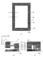
FIG. 1 is a schematic view of a pellicle support frame 111 according to an embodiment of the present invention. FIG. 1A is a schematic view of the pellicle support frame 111 viewed from the side where the pellicle film is arranged in the plane direction of the original plate (mask) on which the pellicle support frame 111 is arranged. The "plane direction of the original plate" is a direction that intersects the plane of the original plate, and in the present embodiment, is a direction that is substantially orthogonal to the plane of the original plate. 1 (b) is a cross-sectional view of the pellicle support frame 111 in the line segment AB of FIG. 1 (a), and FIG. 1 (c) is the support frame 111 for the pellicle in the line segment CD of FIG. 1 (a). It is a cross-sectional view of. FIG. 2 is a schematic view illustrating details of the first support frame portion 11 and the second support frame portion 16 constituting the pellicle support frame 111. FIG. 2A is a schematic view for explaining the details of the first support frame portion 11, and FIG. 2B is a schematic diagram for explaining the details of the second support frame portion 16. 2 (c) and 2 (d) are schematic views illustrating a method of sandwiching and fixing the filter 30 by the first support frame portion 11 and the second support frame portion 16. Further, FIGS. 3A to 3C show a method of engaging the first engaging portion 11b with the second engaging portion 16b on the side where the pellicle film is arranged on the pellicle support frame 111. It is a schematic view seen on the 1st surface a of the 2nd support frame part 16 located on the side of the 1st support frame part 11 in the plane direction of the original plate on which the support frame 111 for pellicle is arranged.

ペリクル用支持枠111は、第1の支持枠部11と、第2の支持枠部16と、フィルタ30と、を有する。フィルタ30は平板状の枠形状を有する。また、フィルタ30は第1の支持枠部11と第2の支持枠部16とに挟持される。ペリクル用支持枠111において、通気孔1は、ペリクル用支持枠111の内側(ペリクルを原版に装着した場合に閉空間が形成される側である。なお、ペリクルを原版に装着した場合の閉空間部分について、矢印Pにて示した。)ではペリクル用支持枠111の厚み方向L1(ペリクル膜の面方向と交差する方向であり、本実施形態においては、ペリクル膜の面方向に略直交する方向である。以下、第1の方向とも称する。)に延伸する孔3(第1の孔とも称する)と、孔3に接続し、第1の方向L1と交差する第2の方向L2(ペリクル膜の面方向と略平行な方向)に延伸する孔5(第2の孔とも称する)を有する。孔3はペリクル用支持枠111の内縁部に開口を有し、孔5は閉空間部分Pの外部へと延伸し、ペリクル用支持枠111の外縁部に開口を有する。 The pellicle support frame 111 has a first support frame portion 11, a second support frame portion 16, and a filter 30. The filter 30 has a flat frame shape. Further, the filter 30 is sandwiched between the first support frame portion 11 and the second support frame portion 16. In the pellicle support frame 111, the ventilation hole 1 is the inside of the pellicle support frame 111 (the side where a closed space is formed when the pellicle is mounted on the original plate. The closed space when the pellicle is mounted on the original plate. The portion is indicated by an arrow P) in the thickness direction L1 of the pellicle support frame 111 (the direction intersecting the surface direction of the pellicle film), and in the present embodiment, the direction substantially orthogonal to the surface direction of the pellicle film. A hole 3 (also referred to as a first hole) extending in the first direction (hereinafter, also referred to as a first direction) and a second direction L2 (pellicle film) connected to the hole 3 and intersecting the first direction L1. It has a hole 5 (also referred to as a second hole) extending in a direction substantially parallel to the plane direction of the above. The hole 3 has an opening at the inner edge of the pellicle support frame 111, and the hole 5 extends to the outside of the closed space portion P and has an opening at the outer edge of the pellicle support frame 111.

図1(a)及び図1(b)に示すように、フィルタ30を配置するため、一実施形態として、第1の支持枠部11は、上面の一部を切り欠いた階段状の構造を有する切り欠き部Nを有する。本実施形態においては、第1の支持枠部11と第2の支持枠部16とによりフィルタ30を挟持することによりペリクル用支持枠111に固定するため、第1の支持枠部11に切り欠き部Nを配置することにより、ペリクル用支持枠111の内縁部に孔3を配置することができる。また、後述するように、ペリクル膜またはペリクル枠体をペリクル用支持枠111の上面に配置することにより、ペリクルを得ることができる。したがって、本発明の一実施形態に係るペリクルにおいては、フィルタ30がペリクル膜から離間して配置される。 As shown in FIGS. 1A and 1B, in order to arrange the filter 30, as one embodiment, the first support frame portion 11 has a stepped structure in which a part of the upper surface is cut out. It has a notch N having a notch. In the present embodiment, the filter 30 is sandwiched between the first support frame portion 11 and the second support frame portion 16 to be fixed to the pellicle support frame 111, so that the first support frame portion 11 is notched. By arranging the portion N, the hole 3 can be arranged at the inner edge portion of the pellicle support frame 111. Further, as will be described later, the pellicle can be obtained by arranging the pellicle film or the pellicle frame on the upper surface of the pellicle support frame 111. Therefore, in the pellicle according to the embodiment of the present invention, the filter 30 is arranged apart from the pellicle membrane.

第1の支持枠部11は、平板状の枠形状を有する第1の本体部11aと、第1の本体部11aからペリクル用支持枠111の厚み方向L1に突出した第1の係合部11bを有する。第2の支持枠部16は、平板状の枠形状を有する第2の本体部16aと、第2の本体部16aのペリクル用支持枠111の第1の方向L1に設けられた凹部に配置され、第1の係合部11bと係合する第2の係合部16bを有する。 The first support frame portion 11 includes a first main body portion 11a having a flat plate-like frame shape, and a first engaging portion 11b protruding from the first main body portion 11a in the thickness direction L1 of the pellicle support frame 111. Have. The second support frame portion 16 is arranged in a second main body portion 16a having a flat plate-like frame shape and a recess provided in the first direction L1 of the pellicle support frame 111 of the second main body portion 16a. , Has a second engaging portion 16b that engages with the first engaging portion 11b.

第1の係合部11bは、第1の本体部11aからペリクル用支持枠111の第1の方向L1に延在する第1の延在部11cと、第1の延在部11cの第1の本体部11aとは反対側の端部からペリクル用支持枠111の第1の方向L1と交差する第2の方向L2に延在する第2の延在部11dと、を有する。第2の係合部16bは、第1の支持枠部11側に位置する第2の支持枠部16の第1の面aからペリクル用支持枠111の第1の方向L1に延在する第1の溝部16cと、第1の溝部16cの底部からペリクル用支持枠111の第1の方向L1と交差する第2の方向L2に延在する第2の溝部16dとを有する。第2の延在部11dの少なくとも一部は、第2の溝部16dに収容される。 The first engaging portion 11b includes a first extending portion 11c extending from the first main body portion 11a in the first direction L1 of the pellicle support frame 111, and a first extending portion 11c of the first extending portion 11c. It has a second extending portion 11d extending in a second direction L2 intersecting the first direction L1 of the pellicle support frame 111 from an end portion opposite to the main body portion 11a. The second engaging portion 16b extends from the first surface a of the second support frame portion 16 located on the side of the first support frame portion 11 to the first direction L1 of the pellicle support frame 111. It has a groove portion 16c of 1 and a second groove portion 16d extending from the bottom portion of the first groove portion 16c in a second direction L2 intersecting the first direction L1 of the pellicle support frame 111. At least a part of the second extending portion 11d is housed in the second groove portion 16d.

本実施形態に係る第1の支持枠部11及び第2の支持枠部16は、例えば、鋳造や射出成形により形成することができるが、これらに限定されるものではない。例えば、第1の本体部11aに第1の係合部11bを接続して、第1の支持枠部11を形成してもよい。また、平板状の枠形状の部材をエッチングすることにより第2の支持枠部16を形成してもよい。第1の支持枠部11及び第2の支持枠部16の材料としては金属、ガラス、シリコンウエハ、セラミクス、樹脂等が挙げられる。 The first support frame portion 11 and the second support frame portion 16 according to the present embodiment can be formed by, for example, casting or injection molding, but are not limited thereto. For example, the first engaging portion 11b may be connected to the first main body portion 11a to form the first support frame portion 11. Further, the second support frame portion 16 may be formed by etching a flat plate-shaped frame-shaped member. Examples of the material of the first support frame portion 11 and the second support frame portion 16 include metal, glass, silicon wafer, ceramics, resin and the like.

フィルタ30は、第1の係合部11b及び第2の係合部16bに対応する位置に開口bを有し、第1の係合部11bは、開口bを貫通して、第2の係合部16bと係合する。このような係合は、第1の支持枠部11の第1の係合部11bを、フィルタ30の開口bに通し、さらに、ペリクル用支持枠111の第1の方向L1に向かって第2の支持枠部16の第1の溝部16cに挿入し、第2の支持枠部16の底部に第1の係合部11bが到達した時点で第1の支持枠部11をペリクル用支持枠111の第1の方向L1と交差する第2の方向L2にスライドさせることにより行うことができる。このとき、第1の本体部11a、フィルタ30及び第2の本体部16aは、同一又は概略同一の幅を有する枠形状であるため、一体化してペリクル用支持枠111を構成することができる。本実施形態においては、フィルタ30は、平板状の枠形状を有する1つの部材であるため、通気孔毎にフィルタを配置する必要はなく、ペリクル用支持枠111に簡便に取り付けることができる。このようにして、ペリクル用支持枠111の内縁部と外縁部とを接続し、フィルタ30が配置された通気孔1が構成される。 The filter 30 has an opening b at a position corresponding to the first engaging portion 11b and the second engaging portion 16b, and the first engaging portion 11b penetrates the opening b and engages in a second engagement. Engage with the joint 16b. In such an engagement, the first engaging portion 11b of the first support frame portion 11 is passed through the opening b of the filter 30, and further, the pellicle support frame 111 is second toward the first direction L1. The first support frame portion 11 is inserted into the first groove portion 16c of the support frame portion 16 of the above, and when the first engaging portion 11b reaches the bottom portion of the second support frame portion 16, the first support frame portion 11 is inserted into the support frame 111 for the pellicle. This can be done by sliding in the second direction L2 which intersects the first direction L1 of. At this time, since the first main body portion 11a, the filter 30 and the second main body portion 16a have a frame shape having the same or substantially the same width, the pellicle support frame 111 can be integrated. In the present embodiment, since the filter 30 is one member having a flat plate-shaped frame shape, it is not necessary to arrange the filter for each ventilation hole, and the filter 30 can be easily attached to the pellicle support frame 111. In this way, the inner edge portion and the outer edge portion of the pellicle support frame 111 are connected to form the ventilation hole 1 in which the filter 30 is arranged.

フィルタ30はHEPA、ULPAなどのメンブレンフィルタ、不織布フィルタ、カーボンナノチューブやセルロースなどファイバーを積層したフィルタ、セラミックスフィルタ、ガラスフィルタ、金属焼結フィルタ、中空紙フィルタなどを利用することができる。本発明の一実施形態に係るペリクル用支持枠111は、フィルタ30の通気抵抗が高い場合であっても、通気口の面積を大きくとることができるため、真空引きを行う時間を低減することが可能であり、好ましくは、フィルタ30は、初期圧力損失が100Pa以上550Pa以下であり、粒径が0.15μm以上0.3μm以下の粒子に対して粒子捕集率が99.7%以上100%以下の特性を有するフィルタである。また、通気孔1が複数設けられる場合においては、複数の通気孔1に位置するフィルタ30の合計の面積、即ちペリクルの内側と外側との換気に有効なフィルタ30の合計の面積が100mm2以上2000mm2以下であることが好ましい。なお、このフィルタに関する説明は、各実施形態で共通するため、以下では説明を省略する。As the filter 30, a membrane filter such as HEPA or ULPA, a non-woven fabric filter, a filter in which fibers such as carbon nanotubes and cellulose are laminated, a ceramic filter, a glass filter, a metal sintered filter, a hollow paper filter and the like can be used. The pellicle support frame 111 according to the embodiment of the present invention can increase the area of the ventilation port even when the ventilation resistance of the filter 30 is high, so that the time for vacuuming can be reduced. It is possible, and preferably, the filter 30 has a particle collection rate of 99.7% or more and 100% with respect to particles having an initial pressure loss of 100 Pa or more and 550 Pa or less and a particle size of 0.15 μm or more and 0.3 μm or less. It is a filter having the following characteristics. When a plurality of ventilation holes 1 are provided, the total area of the filters 30 located in the plurality of ventilation holes 1, that is, the total area of the filters 30 effective for ventilation inside and outside the pellicle is 100 mm 2 or more. It is preferably 2000 mm 2 or less. Since the description of this filter is common to each embodiment, the description thereof will be omitted below.

ペリクル用支持枠111においては、第1の支持枠部11と第2の支持枠部16とによりフィルタ30を挟持し、第1の係合部11bと第2の係合部16bとを係合することにより、フィルタ30を固定している。本実施形態においては、フィルタ30を固定するために接着剤を用いていないため、第1の係合部11bと第2の係合部16bとにより係合している第1の支持枠部11と第2の支持枠部16を分離することにより、ペリクル用支持枠111からフィルタ30を簡便に取り外すことができる。即ち、第1の支持枠部11を第2の方向L2とは反対側の方向にスライドさせる、又は第2の支持枠部16を第2の方向L2にスライドさせることにより、第1の係合部11bと第2の係合部16bとの係合を解除する。その後、第1の支持枠部11を第1の方向L1とは反対側の方向に持ち上げる、又は第2の支持枠部16を第1の方向L1へ下ろすことにより、第1の支持枠部11と第2の支持枠部16を分離することができる。 In the pellicle support frame 111, the filter 30 is sandwiched between the first support frame portion 11 and the second support frame portion 16, and the first engaging portion 11b and the second engaging portion 16b are engaged with each other. By doing so, the filter 30 is fixed. In the present embodiment, since no adhesive is used to fix the filter 30, the first support frame portion 11 is engaged by the first engaging portion 11b and the second engaging portion 16b. By separating the second support frame portion 16 and the second support frame portion 16, the filter 30 can be easily removed from the pellicle support frame 111. That is, by sliding the first support frame portion 11 in the direction opposite to the second direction L2, or by sliding the second support frame portion 16 in the second direction L2, the first engagement The engagement between the portion 11b and the second engaging portion 16b is released. After that, by lifting the first support frame portion 11 in the direction opposite to the first direction L1 or lowering the second support frame portion 16 in the first direction L1, the first support frame portion 11 And the second support frame portion 16 can be separated.

従来のペリクルにおいては、通気孔毎にフィルタを配置していたため、それぞれのフィルタを取り外す必要があった。本実施形態においては、フィルタ30は、平板状の枠形状を有する1つの部材であるため、第1の支持枠部11と第2の支持枠部16を分離すれば、ペリクル用支持枠111から容易に取り外すことができる。 In the conventional pellicle, since the filter is arranged for each ventilation hole, it is necessary to remove each filter. In the present embodiment, since the filter 30 is one member having a flat plate-like frame shape, if the first support frame portion 11 and the second support frame portion 16 are separated, the pellicle support frame 111 can be used. It can be easily removed.

また、一実施形態において、フィルタ30として新しいフィルタを第1の支持枠部11と第2の支持枠部16とにより再度挟持することにより、フィルタ30を簡便に交換することができる。また、本実施形態においては、フィルタ30を固定するために接着剤を用いていないため、接着剤からのアウトガスの発生が低減され、原版とペリクルとによって形成される空間内のEUV光が照射される領域におけるコンタミネーションが抑制される。また、接着剤からのアウトガスによる露光装置の光学系のレンズに曇りを生じさせたり、露光不良や光量不足が生じたりすることを抑制することができる。 Further, in one embodiment, the filter 30 can be easily replaced by sandwiching the new filter as the filter 30 between the first support frame portion 11 and the second support frame portion 16 again. Further, in the present embodiment, since no adhesive is used to fix the filter 30, the generation of outgas from the adhesive is reduced, and EUV light in the space formed by the original plate and the pellicle is irradiated. Contamination in the area is suppressed. In addition, it is possible to suppress the occurrence of fogging in the lens of the optical system of the exposure apparatus due to the outgas from the adhesive, and the occurrence of poor exposure or insufficient light intensity.

ペリクル用支持枠111は、平板状の枠形状を有する第1の本体部11aと、第1の本体部11aからペリクル用支持枠111の厚み方向に突出した第1の係合部11bと、を有する第1の支持枠部11を準備し、平板状の枠形状を有する第2の本体部16aと、第2の本体部16aのペリクル用支持枠111の厚み方向に設けられた凹部に配置され、第1の係合部11bと係合する第2の係合部16bと、を有する第2の支持枠部16を準備し、平板状の枠形状を有するフィルタ30を準備し、フィルタ30を第1の支持枠部11と第2の支持枠部16とを挟持し、第1の係合部11bと第2の係合部16bとを係合することにより製造することができる。 The pellicle support frame 111 includes a first main body portion 11a having a flat plate-like frame shape, and a first engaging portion 11b protruding from the first main body portion 11a in the thickness direction of the pellicle support frame 111. The first support frame portion 11 to be provided is prepared, and is arranged in a recess provided in the thickness direction of the second main body portion 16a having a flat plate-shaped frame shape and the pellicle support frame 111 of the second main body portion 16a. , A second support frame portion 16 having a second engaging portion 16b that engages with the first engaging portion 11b is prepared, a filter 30 having a flat plate-shaped frame shape is prepared, and the filter 30 is used. It can be manufactured by sandwiching the first support frame portion 11 and the second support frame portion 16 and engaging the first engaging portion 11b and the second engaging portion 16b.

[実施形態2]
上述した実施形態1においては、第1の本体部11aと第1の係合部11bを一体成型、又は第1の本体部11aに第1の係合部11bを接続した第1の支持枠部11を用いる例を示したが、本発明に係るペリクル用支持枠及びペリクルはこれらに限定されるものではない。複数の板状の部材を積層して第1の支持枠部及び第2の支持枠部を構成する例について、実施形態2として説明する。以下においては、実施形態1とは異なる構成について、特に説明し、実施形態1と同様の構成については説明を省略する。
[Embodiment 2]
In the first embodiment described above, the first main body portion 11a and the first engaging portion 11b are integrally molded, or the first engaging portion 11b is connected to the first main body portion 11a. Although an example in which 11 is used is shown, the support frame for pellicle and the pellicle according to the present invention are not limited thereto. An example in which a plurality of plate-shaped members are laminated to form a first support frame portion and a second support frame portion will be described as the second embodiment. In the following, a configuration different from that of the first embodiment will be particularly described, and a description of the same configuration as that of the first embodiment will be omitted.

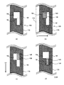
図4は、本発明の一実施形態に係るペリクル用支持枠111Aの模式図である。図4(a)は、ペリクル用支持枠111Aをペリクル膜が配置される側からペリクル用支持枠111Aが配置される原版の面方向に見た模式図である。図4(b)は、図4(a)の線分ABにおけるペリクル用支持枠111Aの断面図であり、図4(c)は、図4(a)の線分CDにおけるペリクル用支持枠111Aの断面図である。図5は、ペリクル用支持枠111Aを構成する第1の支持枠部11Aと第2の支持枠部16Aの詳細を説明する模式図である。図5(a)は第1の支持枠部11Aの詳細を説明する模式図であり、図5(b)は第2の支持枠部16Aの詳細を説明する模式図である。また、図5(c)及び図5(d)は、第1の支持枠部11Aと第2の支持枠部16Aとにより、フィルタ30を挟持して固定する方法を説明する模式図である。 FIG. 4 is a schematic view of a pellicle support frame 111A according to an embodiment of the present invention. FIG. 4A is a schematic view of the pellicle support frame 111A viewed from the side where the pellicle film is arranged in the plane direction of the original plate on which the pellicle support frame 111A is arranged. 4 (b) is a cross-sectional view of the pellicle support frame 111A in the line segment AB of FIG. 4 (a), and FIG. 4 (c) is the support frame 111A for the pellicle in the line segment CD of FIG. 4 (a). It is a cross-sectional view of. FIG. 5 is a schematic view illustrating details of the first support frame portion 11A and the second support frame portion 16A constituting the support frame 111A for the pellicle. FIG. 5A is a schematic view illustrating the details of the first support frame portion 11A, and FIG. 5B is a schematic diagram illustrating the details of the second support frame portion 16A. Further, FIGS. 5 (c) and 5 (d) are schematic views illustrating a method of sandwiching and fixing the filter 30 by the first support frame portion 11A and the second support frame portion 16A.

ペリクル用支持枠111Aは、第1の支持枠部11Aと、第2の支持枠部16Aと、フィルタ30と、を有する。フィルタ30は第1の支持枠部11Aと第2の支持枠部16Aとにより挟持される。第1の支持枠部11Aは、例えば、平板状の枠形状を有する薄板12Aと、薄板12Aの下面に配置された平板状の枠形状を有する薄板13Aとが積層して構成された第1の本体部11aを有する。また、本実施形態においては、第1の支持枠部11の切り欠き部Nは、薄板13Aの上面に薄板12Aを配置することにより構成され、第1の方向L1に延伸する孔3をペリクル用支持枠111Aの内縁部に配置することができる。
The pellicle support frame 111A includes a first support frame portion 11A, a second support frame portion 16A, and a filter 30. The filter 30 is sandwiched between the first support frame portion 11A and the second support frame portion 16A. The first support frame portion 11A is formed by, for example, laminating a thin plate 12A having a flat plate-like frame shape and a thin plate 13A having a flat plate-like frame shape arranged on the lower surface of the thin plate 12A. It has a main body 11a. In the present embodiment, notches N of the first support frame portion 11 A is constructed by arranging the thin plate 12A on the upper surface of the thin plate 13A, a hole 3 extending in the first direction L1 pellicle It can be arranged at the inner edge of the support frame 111A.

第1の支持枠部11Aは、薄板13Aの下面からペリクル用支持枠111Aの第1の方向L1に延在する薄板14Aと、薄板14Aの下面に配置され、薄板14Aからペリクル用支持枠111Aの第1の方向L1と交差する第2の方向L2に延在する薄板15Aとが積層して構成された第1の係合部11bを有する。本実施形態においては、第1の本体部11aからペリクル用支持枠111Aの第1の方向L1に延在する第1の延在部11cは、薄板14Aにより構成される。また、第1の延在部11cの第1の本体部11aとは反対側の端部から第2の方向L2に延在する第2の延在部11dは、薄板15Aにより構成される。 The first support frame portion 11A is arranged on the lower surface of the thin plate 14A extending from the lower surface of the thin plate 13A to the first direction L1 of the pellicle support frame 111A and the lower surface of the thin plate 14A, and from the thin plate 14A to the pellicle support frame 111A. It has a first engaging portion 11b formed by laminating a thin plate 15A extending in a second direction L2 intersecting with a first direction L1. In the present embodiment, the first extending portion 11c extending from the first main body portion 11a to the first direction L1 of the pellicle support frame 111A is composed of the thin plate 14A. Further, the second extending portion 11d extending in the second direction L2 from the end portion of the first extending portion 11c opposite to the first main body portion 11a is formed of a thin plate 15A.

第2の支持枠部16Aは、平板状の枠形状を有する薄板19Aの上面に平板状の枠形状を有する薄板18A及び平板状の枠形状を有する薄板17Aが順次積層して構成された第2の本体部16aを有する。また、本実施形態においては、後述するように、薄板18Aの外縁部には凹部が配置され、この凹部を薄板17Aと薄板19Aとにより挟持することにより、ペリクル用支持枠111Aの第2の方向L2に延伸する孔5を配置することができる。 The second support frame portion 16A is formed by sequentially laminating a thin plate 18A having a flat plate shape and a thin plate 17A having a flat frame shape on the upper surface of a thin plate 19A having a flat frame shape. It has a main body portion 16a of. Further, in the present embodiment, as will be described later, a recess is arranged at the outer edge of the thin plate 18A, and by sandwiching the recess between the thin plate 17A and the thin plate 19A, the second direction of the pellicle support frame 111A A hole 5 extending to L2 can be arranged.

薄板17Aには第1の溝部16cが配置され、薄板18Aには第2の溝部16dが配置される。薄板19Aの上面に薄板18A及び薄板17Aを順次積層することにより、第1の方向L1に延在する第1の溝部16cと第2の方向L2に延在する第2の溝部16dとが重畳し、第2の支持枠部16Aに凹部を形成する。この凹部は、第1の係合部11bと係合する第2の係合部16bとして機能する。第2の延在部11dの少なくとも一部は、第2の溝部16dに収容され、第1の係合部11bと第2の係合部16bとが係合する。 The first groove portion 16c is arranged on the thin plate 17A, and the second groove portion 16d is arranged on the thin plate 18A. By sequentially laminating the thin plate 18A and the thin plate 17A on the upper surface of the thin plate 19A, the first groove portion 16c extending in the first direction L1 and the second groove portion 16d extending in the second direction L2 are superimposed. , A recess is formed in the second support frame portion 16A. This recess functions as a second engaging portion 16b that engages with the first engaging portion 11b. At least a part of the second extending portion 11d is housed in the second groove portion 16d, and the first engaging portion 11b and the second engaging portion 16b engage with each other.

ここで、第1の支持枠部11A及び第2の支持枠部16Aを構成する各薄板について、さらに説明する。図6は、薄板12Aの模式図である。図6(a)は、薄板12Aの上面図であり、図6(b)は図6(a)に示した線分ABでの薄板12Aの断面図であり、図6(c)は図6(a)に示した線分CDでの薄板12Aの断面図である。薄板12Aは、例えば、矩形の枠形状であり、枠の内縁部(ペリクル膜が吊架される側であり、ペリクルとして使用した際に閉空間を形成する側である)に接続し、第2の方向に凹んだ凹部(窪み形状)12aを有する。凹部12aの数に特に限定はなく、ペリクルの閉空間と外部との換気に十分となるフィルタ30のために複数の凹部12aを設けることができる。図6(c)に示したように、凹部12aに隣接する領域は、第1の本体部11aの幅に相当する幅を有し、第1の支持枠部11Aに必要な強度を付与する。薄板12Aの原料としては金属、ガラス、シリコンウエハ、セラミクス、樹脂が挙げられる。本実施形態では、凹部12aが形成する開口が、第1の方向L1の孔に相当する。 Here, each thin plate constituting the first support frame portion 11A and the second support frame portion 16A will be further described. FIG. 6 is a schematic view of the thin plate 12A. 6 (a) is a top view of the thin plate 12A, FIG. 6 (b) is a cross-sectional view of the thin plate 12A at the line segment AB shown in FIG. 6 (a), and FIG. 6 (c) is FIG. It is sectional drawing of the thin plate 12A in the line segment CD shown in (a). The thin plate 12A has, for example, a rectangular frame shape, is connected to the inner edge of the frame (the side on which the pellicle film is suspended, and the side that forms a closed space when used as a pellicle), and is connected to a second. It has a concave portion (recessed shape) 12a recessed in the direction of. The number of recesses 12a is not particularly limited, and a plurality of recesses 12a may be provided for the filter 30 which is sufficient for ventilation between the closed space of the pellicle and the outside. As shown in FIG. 6C, the region adjacent to the recess 12a has a width corresponding to the width of the first main body portion 11a, and imparts the necessary strength to the first support frame portion 11A. Examples of the raw material of the thin plate 12A include metal, glass, silicon wafer, ceramics, and resin. In the present embodiment, the opening formed by the recess 12a corresponds to the hole in the first direction L1.

図7は、薄板13Aの模式図である。図7(a)は、薄板13Aの上面図であり、図7(b)は図7(a)に示した線分ABでの薄板13Aの断面図であり、図7(c)は図7(a)に示した線分CDでの薄板13Aの断面図である。薄板13Aは、例えば、矩形の枠形状であり、第1の方向L1に開口した開口部13aを有する。凹部12aと開口部13aとは、少なくとも一部が重畳し、第1の方向L1に延伸する孔3を構成する。開口部13aの数に特に限定はなく、凹部12aに対応する数を設けることができる。図7(c)に示したように、開口部13aに隣接する領域は、第1の本体部11aの幅に相当する幅を有し、第1の支持枠部11Aに必要な強度を付与する。薄板13Aの原料としては金属、ガラス、シリコンウエハ、セラミクス、樹脂が挙げられる。 FIG. 7 is a schematic view of the thin plate 13A. 7 (a) is a top view of the thin plate 13A, FIG. 7 (b) is a cross-sectional view of the thin plate 13A at the line segment AB shown in FIG. 7 (a), and FIG. 7 (c) is FIG. 7. It is sectional drawing of the thin plate 13A in the line segment CD shown in (a). The thin plate 13A has, for example, a rectangular frame shape and has an opening 13a opened in the first direction L1. At least a part of the recess 12a and the opening 13a overlap each other to form a hole 3 extending in the first direction L1. The number of openings 13a is not particularly limited, and a number corresponding to the recesses 12a can be provided. As shown in FIG. 7C, the region adjacent to the opening 13a has a width corresponding to the width of the first main body portion 11a, and imparts the necessary strength to the first support frame portion 11A. .. Examples of the raw material of the thin plate 13A include metal, glass, silicon wafer, ceramics, and resin.

図8は、薄板14Aの模式図である。図8(a)は、薄板14Aの上面図であり、図8(b)は図8(a)に示した線分CDでの薄板14Aの断面図である。薄板14Aは、例えば、矩形の形状であり、薄板13Aの下面に接続し、第1の本体部11aからペリクル用支持枠111Aの第1の方向L1に延在する第1の延在部11cを構成する。薄板14Aは、開口部13aが配置される薄板13Aの領域に隣接する領域に配置される。薄板14Aの数に特に限定はなく、開口部13aの両隣に位置する薄板13Aの領域に配置されることが好ましい。即ち、本実施形態においては、第1の係合部11bと第2の係合部16bが通気孔1の両側に配置されることにより、第1の支持枠部11Aと第2の支持枠部16Aとが係合する強度を高めることができ、フィルタを介して通気する際の空気漏れが少なくなる。薄板14Aの原料としては金属、ガラス、シリコンウエハ、セラミクス、樹脂が挙げられる。 FIG. 8 is a schematic view of the thin plate 14A. FIG. 8A is a top view of the thin plate 14A, and FIG. 8B is a cross-sectional view of the thin plate 14A on the line segment CD shown in FIG. 8A. The thin plate 14A has, for example, a rectangular shape, and is connected to the lower surface of the thin plate 13A, and has a first extending portion 11c extending from the first main body portion 11a in the first direction L1 of the pellicle support frame 111A. Constitute. The thin plate 14A is arranged in a region adjacent to the region of the thin plate 13A in which the opening 13a is arranged. The number of the thin plates 14A is not particularly limited, and it is preferable that the thin plates 14A are arranged in the region of the thin plates 13A located on both sides of the opening 13a. That is, in the present embodiment, the first engaging portion 11b and the second engaging portion 16b are arranged on both sides of the ventilation hole 1, so that the first supporting frame portion 11A and the second supporting frame portion are arranged. The strength of engagement with 16A can be increased, and air leakage during ventilation through the filter is reduced. Examples of the raw material of the thin plate 14A include metal, glass, silicon wafer, ceramics, and resin.

図9は、薄板15Aの模式図である。図9(a)は、薄板15Aの上面図であり、図9(b)は図9(a)に示した線分CDでの薄板15Aの断面図である。薄板15Aは、例えば、矩形の形状であり、薄板14Aの下面に接続し、ペリクル用支持枠111Aの第2の方向L2に延在する第2の延在部11dを構成する。このため、薄板15Aは、薄板14Aよりも第2の方向L2に所定の長さで延在する。薄板14Aから第2の方向L2に延在する薄板15Aの部分は、第2の係合部16bとの係合に関与する。ここで、第2の方向L2に延在する薄板15Aの部分の長さは、第1の支持枠部11Aと第2の支持枠部16Aとが係合する強度が得られる範囲で任意に設定可能である。第2の方向L2に延在する薄板15Aの部分を長くすると、第1の支持枠部11Aと第2の支持枠部16Aとの係合の確実性が高まる。一方、フィルタ30を第1の支持枠部11Aと第2の支持枠部16Aで挟んで固定する際の、第1の支持枠部11Aがフィルタ30に接して第2の方向L2に移動する距離が長くなると、第1の支持枠部11Aとフィルタ30との摩擦によりフィルタ30からの塵埃が生じるおそれがある。薄板15Aは、薄板15Aの数に特に限定はなく、薄板14Aの数に応じた数で配置される。薄板15Aの原料としては金属、ガラス、シリコンウエハ、セラミクス、樹脂が挙げられる。 FIG. 9 is a schematic view of the thin plate 15A. 9 (a) is a top view of the thin plate 15A, and FIG. 9 (b) is a cross-sectional view of the thin plate 15A with the line segment CD shown in FIG. 9 (a). The thin plate 15A has, for example, a rectangular shape, is connected to the lower surface of the thin plate 14A, and constitutes a second extending portion 11d extending in the second direction L2 of the pellicle support frame 111A. Therefore, the thin plate 15A extends in the second direction L2 with a predetermined length as compared with the thin plate 14A. The portion of the thin plate 15A extending from the thin plate 14A in the second direction L2 participates in the engagement with the second engaging portion 16b. Here, the length of the portion of the thin plate 15A extending in the second direction L2 is arbitrarily set within a range in which the strength with which the first support frame portion 11A and the second support frame portion 16A are engaged can be obtained. It is possible. When the portion of the thin plate 15A extending in the second direction L2 is lengthened, the certainty of engagement between the first support frame portion 11A and the second support frame portion 16A is increased. On the other hand, the distance at which the first support frame portion 11A comes into contact with the filter 30 and moves in the second direction L2 when the filter 30 is sandwiched and fixed between the first support frame portion 11A and the second support frame portion 16A. If becomes longer, dust from the filter 30 may be generated due to friction between the first support frame portion 11A and the filter 30. The number of thin plates 15A is not particularly limited, and the number of thin plates 15A is arranged according to the number of thin plates 14A. Examples of the raw material of the thin plate 15A include metal, glass, silicon wafer, ceramics, and resin.

図10は、フィルタ30の模式図である。図10(a)は、フィルタ30の上面図であり、図10(b)は図10(a)に示した線分ABでのフィルタ30の断面図であり、図10(c)は図10(a)に示した線分CDでのフィルタ30の断面図である。フィルタ30は、例えば、矩形の形状であり、第1の係合部11b及び第2の係合部16bに対応する位置に開口bを有する。即ち、開口bは、薄板13Aの開口部13aが配置される領域に隣接する領域に対応するフィルタ30の位置に配置される。フィルタ30において、ペリクル用支持枠111Aのフィルタとして機能するのは、通気孔1に対応する部分である。その他のフィルタ30の構成は実施形態1で説明した構成と同様の構成であってもよく、詳細な説明は省略する。 FIG. 10 is a schematic view of the filter 30. 10 (a) is a top view of the filter 30, FIG. 10 (b) is a cross-sectional view of the filter 30 at the line segment AB shown in FIG. 10 (a), and FIG. 10 (c) is a cross-sectional view of the filter 30. It is sectional drawing of the filter 30 in the line segment CD shown in (a). The filter 30 has, for example, a rectangular shape and has an opening b at a position corresponding to the first engaging portion 11b and the second engaging portion 16b. That is, the opening b is arranged at the position of the filter 30 corresponding to the area adjacent to the area where the opening 13a of the thin plate 13A is arranged. In the filter 30, it is the portion corresponding to the ventilation hole 1 that functions as the filter of the pellicle support frame 111A. The other configurations of the filter 30 may be the same as the configurations described in the first embodiment, and detailed description thereof will be omitted.

図11は、薄板17Aの模式図である。図11(a)は、薄板17Aの上面図であり、図11(b)は図11(a)に示した線分ABでの薄板17Aの断面図であり、図11(c)は図11(a)に示した線分CDでの薄板17Aの断面図である。薄板17Aは、例えば、矩形の枠形状であり、第1の方向L1に開口した開口部17aと、開口部17aに隣接して配置される開口部17bとを有する。開口部17aは、薄板13Aの開口部13aに対応する位置に配置され、開口部13aとともに第1の方向L1に延伸する孔3を構成する。また、開口部17bは、第1の方向L1に延在する第1の溝部16cに対応し、第2の係合部16bを構成する。開口部17aの数に特に限定はなく、第1の支持枠部11Aに配置された第1の係合部11bに対応する位置に配置することができる。薄板17Aの原料としては金属、ガラス、シリコンウエハ、セラミクス、樹脂が挙げられる。 FIG. 11 is a schematic view of the thin plate 17A. 11 (a) is a top view of the thin plate 17A, FIG. 11 (b) is a cross-sectional view of the thin plate 17A at the line segment AB shown in FIG. 11 (a), and FIG. 11 (c) is FIG. 11 It is sectional drawing of the thin plate 17A in the line segment CD shown in (a). The thin plate 17A has, for example, a rectangular frame shape, and has an opening 17a opened in the first direction L1 and an opening 17b arranged adjacent to the opening 17a. The opening 17a is arranged at a position corresponding to the opening 13a of the thin plate 13A, and constitutes a hole 3 extending in the first direction L1 together with the opening 13a. Further, the opening 17b corresponds to the first groove 16c extending in the first direction L1 and constitutes the second engaging portion 16b. The number of openings 17a is not particularly limited, and can be arranged at a position corresponding to the first engaging portion 11b arranged in the first support frame portion 11A. Examples of the raw material of the thin plate 17A include metal, glass, silicon wafer, ceramics, and resin.

図12は、薄板18Aの模式図である。図12(a)は、薄板18Aの上面図であり、図12(b)は図12(a)に示した線分ABでの薄板18Aの断面図であり、図12(c)は図12(a)に示した線分CDでの薄板18Aの断面図である。薄板18Aは、例えば、矩形の枠形状であり、枠の外縁部(ペリクルとして使用した際に閉空間を形成しない側である)に接続し、第2の方向に凹んだ凹部(窪み形状)18aを有する。凹部18aの数に特に限定はなく、ペリクルの閉空間と外部との換気に十分となるフィルタ30のために複数の開口を設けることができる。本実施形態では、薄板17Aと薄板19Aとにより挟持される凹部18aが形成する孔が、ペリクル用支持枠111Aの外縁部(ペリクル用支持枠111Aの内側とは反対側であり、ペリクルとして使用した際に閉空間を形成しない側である)に接続し、第2の方向L2に延伸する孔5に相当する。また、薄板18Aは、開口部17aよりも第2の方向L2に大きな所定の幅で開口した開口部18bを有する。開口部18bは、薄板17Aと薄板19Aとにより挟持することにより、第2の方向L2に延伸する第2の溝部16dを構成する。第1の溝部16cと第2の溝部16dとが接続して、第2の係合部16bを構成する。なお、薄板18A自体の形状も、所望の枠体の形状に応じて形状を適宜設定可能である。開口部17aから第2の方向L2に延在する開口部18bの部分は、第1の係合部11bとの係合に関与する。ここで、第2の方向L2に延在する開口部18bの部分の幅は、第1の支持枠部11Aと第2の支持枠部16Aとが係合する強度が得られる範囲で任意に設定可能である。第2の方向L2に延在する開口部18bの部分の幅を長くすると、第1の支持枠部11Aと第2の支持枠部16Aとの係合の確実性が高まる。一方、フィルタ30を第1の支持枠部11Aと第2の支持枠部16Aで挟んで固定する際の、第1の支持枠部11Aがフィルタ30に接して第2の方向L2に移動する距離が長くなると、第1の支持枠部11Aとフィルタ30との摩擦によりフィルタ30からの塵埃が生じる。薄板18Aの原料としては金属、ガラス、シリコンウエハ、セラミクス、樹脂が挙げられる。 FIG. 12 is a schematic view of the thin plate 18A. 12 (a) is a top view of the thin plate 18A, FIG. 12 (b) is a cross-sectional view of the thin plate 18A at the line segment AB shown in FIG. 12 (a), and FIG. 12 (c) is FIG. It is sectional drawing of the thin plate 18A in the line segment CD shown in (a). The thin plate 18A has, for example, a rectangular frame shape, is connected to the outer edge portion of the frame (the side that does not form a closed space when used as a pellicle), and is recessed in the second direction (recessed shape) 18a. Has. The number of recesses 18a is not particularly limited, and a plurality of openings can be provided for the filter 30 which is sufficient for ventilation between the closed space of the pellicle and the outside. In the present embodiment, the hole formed by the recess 18a sandwiched between the thin plate 17A and the thin plate 19A is the outer edge portion of the pellicle support frame 111A (the side opposite to the inside of the pellicle support frame 111A, and is used as a pellicle. Corresponds to the hole 5 which is connected to (the side that does not form a closed space) and extends in the second direction L2. Further, the thin plate 18A has an opening 18b opened with a predetermined width larger than the opening 17a in the second direction L2. The opening 18b constitutes a second groove 16d extending in the second direction L2 by being sandwiched between the thin plate 17A and the thin plate 19A. The first groove portion 16c and the second groove portion 16d are connected to form the second engaging portion 16b. The shape of the thin plate 18A itself can be appropriately set according to the desired shape of the frame. The portion of the opening 18b extending from the opening 17a in the second direction L2 participates in the engagement with the first engaging portion 11b. Here, the width of the portion of the opening 18b extending in the second direction L2 is arbitrarily set within a range in which the strength for engaging the first support frame portion 11A and the second support frame portion 16A can be obtained. It is possible. Increasing the width of the portion of the opening 18b extending in the second direction L2 increases the certainty of engagement between the first support frame portion 11A and the second support frame portion 16A. On the other hand, the distance at which the first support frame portion 11A comes into contact with the filter 30 and moves in the second direction L2 when the filter 30 is sandwiched and fixed between the first support frame portion 11A and the second support frame portion 16A. When becomes longer, dust is generated from the filter 30 due to friction between the first support frame portion 11A and the filter 30. Examples of the raw material of the thin plate 18A include metal, glass, silicon wafer, ceramics, and resin.

図13は、薄板19Aの模式図である。図13(a)は、薄板19Aの上面図であり、図13(b)は図13(a)に示した線分ABでの薄板19Aの断面図であり、図13(c)は図13(a)に示した線分CDでの薄板19Aの断面図である。薄板19Aはペリクル用支持枠111Aにおいては底板として機能し、例えば、矩形の枠形状であるが、所望の枠体の形状に応じて形状を適宜設定可能である。薄板19Aの原料としては金属、ガラス、シリコンウエハ、セラミクス、樹脂が挙げられる。なお、上述した各薄板は、それぞれ同種の材質から形成された薄板を組み合わせてもよいし、それぞれ異なった材質から形成された薄板を組み合わせてもよいし、一部共通する材質から形成された薄板を組み合わせてもよい。 FIG. 13 is a schematic view of the thin plate 19A. 13 (a) is a top view of the thin plate 19A, FIG. 13 (b) is a cross-sectional view of the thin plate 19A at the line segment AB shown in FIG. 13 (a), and FIG. 13 (c) is FIG. It is sectional drawing of the thin plate 19A in the line segment CD shown in (a). The thin plate 19A functions as a bottom plate in the pellicle support frame 111A, and has, for example, a rectangular frame shape, but the shape can be appropriately set according to the desired frame shape. Examples of the raw material of the thin plate 19A include metal, glass, silicon wafer, ceramics, and resin. The above-mentioned thin plates may be combined with thin plates formed of the same type of material, thin plates formed of different materials may be combined, or thin plates formed of some common materials may be combined. May be combined.

本実施形態では、各薄板の固定は、固定されればよく、特に制限されない。固定方法としては、例えば、粘着シート、接着剤、接合剤、常温接合、ダイレクト接合、原子拡散接合、金属接合、溶着、ハンダ接合、熱圧着、ホットメルト、フラックス接合、面ファスナー、ねじ・ピン・クリップ・カシメ等の機械的固定、磁気を用いて挟み込んで固定する方法などが挙げられる。 In the present embodiment, the fixing of each thin plate may be fixed and is not particularly limited. Examples of fixing methods include adhesive sheets, adhesives, adhesives, room temperature bonding, direct bonding, atomic diffusion bonding, metal bonding, welding, solder bonding, thermal pressure bonding, hot melt, flux bonding, surface fasteners, screws / pins, etc. Examples include mechanical fixing such as clipping and caulking, and a method of sandwiching and fixing using magnetism.

ペリクル用支持枠111Aへのフィルタ30の着脱は、実施形態1で説明した方法により行うことができる。第1の支持枠部11Aの第1の係合部11bを、フィルタ30の開口bに通し、さらに、ペリクル用支持枠111Aの第1の方向L1に向かって第2の支持枠部16Aの第1の溝部16cに挿入し、第2の支持枠部16Aの底部に第1の係合部11bが到達した時点で第1の支持枠部11Aをペリクル用支持枠111Aの第1の方向L1と交差する第2の方向L2にスライドさせることにより、第1の係合部11bと第2の係合部16bとを係合することができる。第1の支持枠部11Aと第2の支持枠部16Aによりフィルタ30を挟持することにより、ペリクル用支持枠111Aの内縁部と外縁部とを接続し、フィルタ30が配置された通気孔1が構成される。本実施形態においては、フィルタ30は、平板状の枠形状を有する1つの部材であるため、通気孔毎にフィルタを配置する必要はなく、ペリクル用支持枠111Aに簡便に取り付けることができる。また、本実施形態においては、フィルタ30を固定するために接着剤を用いていないため、第1の係合部11bと第2の係合部16bとにより係合している第1の支持枠部11Aと第2の支持枠部16Aを分離することにより、ペリクル用支持枠111Aからフィルタ30を簡便に取り外すことができる。従来のペリクルにおいては、通気孔毎にフィルタを配置していたため、それぞれのフィルタを取り外す必要があった。本実施形態においては、フィルタ30は、平板状の枠形状を有する1つの部材であるため、第1の支持枠部11Aと第2の支持枠部16Aを分離すれば、ペリクル用支持枠111Aから容易に取り外すことができる。 The filter 30 can be attached to and detached from the pellicle support frame 111A by the method described in the first embodiment. The first engaging portion 11b of the first support frame portion 11A is passed through the opening b of the filter 30, and the second support frame portion 16A of the second support frame portion 16A is further directed toward the first direction L1 of the pellicle support frame 111A. When the first engaging portion 11b reaches the bottom of the second support frame portion 16A after being inserted into the groove portion 16c of No. 1, the first support frame portion 11A is referred to the first direction L1 of the pellicle support frame 111A. By sliding in the intersecting second direction L2, the first engaging portion 11b and the second engaging portion 16b can be engaged with each other. By sandwiching the filter 30 between the first support frame portion 11A and the second support frame portion 16A, the inner edge portion and the outer edge portion of the pellicle support frame 111A are connected, and the ventilation hole 1 in which the filter 30 is arranged is formed. It is composed. In the present embodiment, since the filter 30 is one member having a flat plate-shaped frame shape, it is not necessary to arrange the filter for each ventilation hole, and the filter 30 can be easily attached to the pellicle support frame 111A. Further, in the present embodiment, since no adhesive is used to fix the filter 30, the first support frame is engaged by the first engaging portion 11b and the second engaging portion 16b. By separating the portion 11A and the second support frame portion 16A, the filter 30 can be easily removed from the pellicle support frame 111A. In the conventional pellicle, since the filter is arranged for each ventilation hole, it is necessary to remove each filter. In the present embodiment, since the filter 30 is one member having a flat plate-like frame shape, if the first support frame portion 11A and the second support frame portion 16A are separated, the pellicle support frame 111A can be separated from the filter 30. It can be easily removed.

また、一実施形態において、フィルタ30として新しいフィルタを第1の支持枠部11Aと第2の支持枠部16Aとにより再度挟持することにより、フィルタ30を簡便に交換することができる。また、本実施形態においては、フィルタ30を固定するために接着剤を用いていないため、接着剤からのアウトガスの発生が低減され、原版とペリクルとによって形成される空間内のEUV光が照射される領域におけるコンタミネーションが抑制される。また、接着剤からのアウトガスによる露光装置の光学系のレンズに曇りを生じさせたり、露光不良や光量不足が生じたりすることを抑制することができる。 Further, in one embodiment, the filter 30 can be easily replaced by sandwiching a new filter as the filter 30 between the first support frame portion 11A and the second support frame portion 16A again. Further, in the present embodiment, since no adhesive is used to fix the filter 30, the generation of outgas from the adhesive is reduced, and EUV light in the space formed by the original plate and the pellicle is irradiated. Contamination in the area is suppressed. In addition, it is possible to suppress the occurrence of fogging in the lens of the optical system of the exposure apparatus due to the outgas from the adhesive, and the occurrence of poor exposure or insufficient light intensity.

なお、本実施形態は、これに限定されず、第2の方向L2に対して、第1の支持枠部11Aの第1の係合部11bを配置する向きと、第2の係合部16bを配置する向きとを逆方向に配置してもよい。すなわち、第1の係合部11bと第2の係合部16bを係合させるときの第2の方向L2のスライド方向と、第1の係合部11bと第2の係合部16bとの係合を解除するときの第2の方向L2のスライド方向を、実施形態2とは第2の方向L2に対して逆方向に設定してもよい。また、フィルタ30を挟持する際に、第1の支持枠部11Aを第2の支持枠部16Aに対してスライドさせる方向を、第1の方向L1に設定してもよい。 The present embodiment is not limited to this, and the direction in which the first engaging portion 11b of the first support frame portion 11A is arranged and the second engaging portion 16b with respect to the second direction L2. May be arranged in the opposite direction to the direction in which the is arranged. That is, the slide direction of the second direction L2 when engaging the first engaging portion 11b and the second engaging portion 16b, and the first engaging portion 11b and the second engaging portion 16b. The slide direction of the second direction L2 when disengaging may be set in the direction opposite to the second direction L2 of the second embodiment. Further, when sandwiching the filter 30, the direction in which the first support frame portion 11A is slid with respect to the second support frame portion 16A may be set to the first direction L1.

[実施形態3]
上述した実施形態においては、第1の支持枠部11を一方向にスライドさせることにより、第1の係合部11bと第2の係合部16bを係合させ、第1の支持枠部11を逆方向にスライドさせることにより、第1の係合部11bと第2の係合部16bの係合を解除した。本実施形態においては、第1の支持枠部11を2つの方向に順次スライドすることによりロックする方法について説明する。
[Embodiment 3]
In the above-described embodiment, by sliding the first support frame portion 11 in one direction, the first engaging portion 11b and the second engaging portion 16b are engaged with each other, and the first support frame portion 11 is engaged. Was slid in the opposite direction to disengage the first engaging portion 11b and the second engaging portion 16b. In the present embodiment, a method of locking the first support frame portion 11 by sliding it in two directions in sequence will be described.

図14は、本発明の一実施形態に係るペリクル用支持枠111Bの模式図である。図14(a)は、ペリクル用支持枠111Bをペリクル膜が配置される側からペリクル用支持枠111Bが配置される原版の面方向に見た模式図である。図14(b)は、図14(a)の線分ABにおけるペリクル用支持枠111Bの断面図であり、図14(c)は、図14(a)の線分CDにおけるペリクル用支持枠111Bの断面図である。図15は、ペリクル用支持枠111Bを構成する第1の支持枠部11Bと第2の支持枠部16Bの詳細を説明する模式図である。図15(a)は第1の支持枠部11Bの詳細を説明する模式図であり、図15(b)は第2の支持枠部16Bの詳細を説明する模式図である。また、図15(c)及び図15(d)は、第1の支持枠部11Bと第2の支持枠部16Bとにより、フィルタ30を挟持して固定する方法を説明する模式図である。また、図16(a)〜図16(d)は、第1の係合部11bを第2の係合部16bと係合させる方法を、ペリクル用支持枠111Bをペリクル膜が配置される側からペリクル用支持枠111Bが配置される原版の面方向に、第1の支持枠部11B側に位置する第2の支持枠部16Bの第1の面aで見た模式図である。 FIG. 14 is a schematic view of a pellicle support frame 111B according to an embodiment of the present invention. FIG. 14A is a schematic view of the pellicle support frame 111B viewed from the side where the pellicle film is arranged in the plane direction of the original plate on which the pellicle support frame 111B is arranged. 14 (b) is a cross-sectional view of the pellicle support frame 111B in the line segment AB of FIG. 14 (a), and FIG. 14 (c) is the support frame 111B for the pellicle in the line segment CD of FIG. 14 (a). It is a cross-sectional view of. FIG. 15 is a schematic view illustrating details of the first support frame portion 11B and the second support frame portion 16B constituting the support frame 111B for the pellicle. FIG. 15A is a schematic view illustrating the details of the first support frame portion 11B, and FIG. 15B is a schematic diagram illustrating the details of the second support frame portion 16B. 15 (c) and 15 (d) are schematic views illustrating a method of sandwiching and fixing the filter 30 by the first support frame portion 11B and the second support frame portion 16B. Further, FIGS. 16A to 16D show a method of engaging the first engaging portion 11b with the second engaging portion 16b on the side where the pellicle film is arranged on the pellicle support frame 111B. It is a schematic view seen on the 1st surface a of the 2nd support frame part 16B located on the 1st support frame part 11B side in the surface direction of the original plate in which the support frame 111B for a pellicle is arranged.

本実施形態においては、L字型の開口部を有する薄板17Bで第1の溝部16eを構成し、L字型の開口部を有する薄板18Bで第2の溝部16fを構成する。第1の溝部16eに第2の溝部16fが接続することにより、第2の係合部16bが構成される。ペリクル用支持枠111Bは、第1の支持枠部11Bと、第2の支持枠部16Bと、フィルタ30と、を有する。フィルタ30は第1の支持枠部11Bと第2の支持枠部16Bとに挟持される。第1の支持枠部11Bは、例えば、上述した平板状の枠形状を有する薄板12Aと、薄板12Aの下面に配置された平板状の枠形状を有する薄板13Aとが積層して構成された第1の本体部11aを有する。また、第1の支持枠部11Bの切り欠き部の構成は、上述した実施形態と同様の構成であってもよく、詳細な説明は省略する。 In the present embodiment, the thin plate 17B having an L-shaped opening constitutes the first groove portion 16e, and the thin plate 18B having the L-shaped opening constitutes the second groove portion 16f. By connecting the second groove portion 16f to the first groove portion 16e, the second engaging portion 16b is formed. The pellicle support frame 111B includes a first support frame portion 11B, a second support frame portion 16B, and a filter 30. The filter 30 is sandwiched between the first support frame portion 11B and the second support frame portion 16B. The first support frame portion 11B is formed by laminating, for example, the above-mentioned thin plate 12A having a flat plate shape and the thin plate 13A having a flat plate shape arranged on the lower surface of the thin plate 12A. It has a main body portion 11a of 1. Further, the structure of the cutout portion of the first support frame portion 11B may be the same as that of the above-described embodiment, and detailed description thereof will be omitted.

第1の支持枠部11Bは、薄板13Aの下面からペリクル用支持枠111Bの第1の方向L1に延在する薄板14Bと、薄板14Bの下面に配置され、薄板14Bからペリクル用支持枠111Bの第1の方向L1と交差する第2の方向L2に延在する薄板15Bとが積層して構成された第1の係合部11bを有する。本実施形態においては、第1の本体部11aからペリクル用支持枠111Bの第1の方向L1に延在する第1の延在部11eは、薄板14Bにより構成される。また、第1の延在部11eの第1の本体部11aとは反対側の端部から第2の方向L2に延在する第2の延在部11fは、薄板15Bにより構成される。 The first support frame portion 11B is arranged on the lower surface of the thin plate 14B extending from the lower surface of the thin plate 13A to the first direction L1 of the pellicle support frame 111B and the lower surface of the thin plate 14B, and from the thin plate 14B to the pellicle support frame 111B. It has a first engaging portion 11b formed by laminating a thin plate 15B extending in a second direction L2 intersecting with a first direction L1. In the present embodiment, the first extending portion 11e extending from the first main body portion 11a to the first direction L1 of the pellicle support frame 111B is formed of a thin plate 14B. Further, the second extending portion 11f extending in the second direction L2 from the end portion of the first extending portion 11e opposite to the first main body portion 11a is formed of a thin plate 15B.

第2の支持枠部16Bは、上述した平板状の枠形状を有する薄板19Aの上面に平板状の枠形状を有する薄板18B及び平板状の枠形状を有する薄板17Bが順次積層して構成された第2の本体部16aを有する。また、本実施形態においては、薄板18Bの外縁部には凹部が配置され、この凹部を薄板17Bと薄板19Aとにより挟持することにより、ペリクル用支持枠111Bの第2の方向L2に延伸する孔5を配置することができる。 The second support frame portion 16B is formed by sequentially laminating a thin plate 18B having a flat plate shape and a thin plate 17B having a flat frame shape on the upper surface of the thin plate 19A having the flat frame shape described above. It has a second main body 16a. Further, in the present embodiment, a recess is arranged at the outer edge of the thin plate 18B, and by sandwiching the recess between the thin plate 17B and the thin plate 19A, a hole extending in the second direction L2 of the pellicle support frame 111B. 5 can be placed.

薄板17Bには第1の溝部16eが配置され、薄板18Bには第2の溝部16fが配置される。薄板19Aの上面に薄板18B及び薄板17Bを順次積層することにより、第2の支持枠部16Bの厚み方向である第1の方向L1に延在し、且つ、第1の方向L1に交差(又は直交)する第2の方向L2(ペリクル膜が配置される面方向)に延在し、その一部が第2の方向L2に交差(又は直交)する第4の方向L4(本実施形態においては第3の方向であるが、上述した実施形態との関係から、本明細書においては第4の方向と称する)に延在する第1の溝部16eと、第1の溝部16eよりも第2の方向L2にさらに延在する第2の溝部16fとが重畳し、第2の支持枠部16Bに凹部を形成する。この凹部は、第1の係合部11bと係合する第2の係合部16bとして機能する。第2の延在部11fの少なくとも一部は、第2の溝部16fに収容され、第1の係合部11bと第2の係合部16bとが係合する。本実施形態においては、第4の方向L4に延在する第1の溝部16eがロック機構16lを構成する。ロック機構16lにおける第1の溝部16eの第2の方向L2の幅は、第1の延在部11eを構成する薄板14Bの幅と概略等しいため、第1の係合部11bが第3の方向(第2の方向L2とは反対の方向)に戻ることにより第1の係合部11bと第2の係合部16bとの係合が解除されるのを防止することができる。
The first groove portion 16e is arranged on the thin plate 17B, and the second groove portion 16f is arranged on the thin plate 18B. By sequentially laminating the thin plate 18B and the thin plate 17B on the upper surface of the thin plate 19A, the thin plate 18B and the thin plate 17B extend in the first direction L1 which is the thickness direction of the second support frame portion 16B and intersect (or cross) the first direction L1. A fourth direction L4 (in the present embodiment) extending in the second direction L2 (orthogonal) (orthogonal) and partially intersecting (or orthogonal to) the second direction L2. Although it is the third direction, the first groove portion 16e extending in the third direction (referred to as the fourth direction in the present specification from the viewpoint of the above-described embodiment) and the second groove portion 16e than the first groove portion 16e. A second groove portion 16f extending further in the direction L2 overlaps with the second groove portion 16f to form a recess in the second support frame portion 16B. This recess functions as a second engaging portion 16b that engages with the first engaging portion 11b. At least a part of the second extending portion 11f is housed in the second groove portion 16f, and the first engaging portion 11b and the second engaging portion 16b engage with each other. In the present embodiment, the first groove portion 16e extending in the fourth direction L4 constitutes the lock mechanism 16l. Since the width of the first groove portion 16e in the lock mechanism 16l in the second direction L2 is substantially equal to the width of the thin plate 14B constituting the first extending portion 11e, the first engaging portion 11b is in the third direction. By returning to (the direction opposite to the second direction L2), it is possible to prevent the first engaging portion 11b and the second engaging portion 16b from being disengaged.

ここで、第1の支持枠部11B及び第2の支持枠部16Bを構成する各薄板について、さらに説明する。薄板12Aについては実施形態2において説明したため、詳細な説明は省略する。また、薄板13Aについても実施形態2において説明したため、詳細な説明は省略する。薄板14Bは、例えば、矩形の形状であり、薄板13Aの下面に接続し、第1の本体部11aからペリクル用支持枠111Bの第1の方向L1に延在する第1の延在部11を構成する。薄板14Bは、開口部16eが配置される薄板13Aの領域に隣接する領域に配置される。薄板14Bの数に特に限定はなく、開口部16eの両隣に位置する薄板13Aの領域に配置されることが好ましい。即ち、本実施形態においては、第1の係合部11bと第2の係合部16bが通気孔1の両側に配置されることにより、第1の支持枠部11Bと第2の支持枠部16Bとが係合する強度を高めることができる。
Here, each thin plate constituting the first support frame portion 11B and the second support frame portion 16B will be further described. Since the thin plate 12A has been described in the second embodiment, detailed description thereof will be omitted. Further, since the thin plate 13A has also been described in the second embodiment, detailed description thereof will be omitted. Sheet 14B is, for example, a rectangular shape, and connected to the lower surface of the thin plate 13A, the first extending portion 11 e extending from the first body portion 11a in the first direction L1 of the pellicle support frame 111B To configure. The thin plate 14B is arranged in a region adjacent to the region of the thin plate 13A in which the opening 16e is arranged. The number of the thin plates 14B is not particularly limited, and it is preferable that the thin plates 14B are arranged in the region of the thin plates 13A located on both sides of the opening 16e. That is, in the present embodiment, the first engaging portion 11b and the second engaging portion 16b are arranged on both sides of the ventilation hole 1, so that the first supporting frame portion 11B and the second supporting frame portion are arranged. The strength with which 16B engages can be increased.

薄板15Bは、例えば、矩形の形状であり、薄板14Bの下面に接続し、ペリクル用支持枠111Bの第2の方向L2に延在する第2の延在部11fを構成する。このため、薄板15Bは、薄板14Bよりも第2の方向L2に所定の長さで延在する点で、薄板15Aとは異なる。その他の薄板15Bの構成は薄板15Aの構成と同様であってもよく、詳細な説明は省略する。
The thin plate 15B has, for example, a rectangular shape, is connected to the lower surface of the thin plate 14B, and constitutes a second extending portion 11f extending in the second direction L2 of the pellicle support frame 111B. Therefore, the thin plate 15B is different from the thin plate 15A in that it extends in the second direction L2 with a predetermined length as compared with the thin plate 14B. The configuration of the other thin plate 15B may be the same as the configuration of the thin plate 15A, and detailed description thereof will be omitted.

図16に示したように、例えば、矩形の枠形状であり、薄板17Bは、第2の方向L2に延在する開口部の一部が第4の方向L4に延在するL字型の第1の溝部16eを有する。第1の溝部16eの第4の方向L4に延在する開口部は、ロック機構16lを構成する。ロック機構16lにおいて、第1の溝部16eの第2の方向L2の幅は、薄板14Bの第2の方向L2の幅と概略等しい。 As shown in FIG. 16, for example, the thin plate 17B has a rectangular frame shape, and the thin plate 17B has an L-shaped first opening extending in the second direction L2 and a part of the opening extends in the fourth direction L4. It has a groove portion 16e of 1. The opening extending in the fourth direction L4 of the first groove portion 16e constitutes the lock mechanism 16l. In the lock mechanism 16l, the width of the first groove portion 16e in the second direction L2 is substantially equal to the width of the thin plate 14B in the second direction L2.

薄板18Bは、矩形の枠形状であり、枠の外縁部に接続し、第2の方向に凹んだ凹部(窪み形状)を有する。凹部の数に特に限定はなく、ペリクルの閉空間と外部との換気に十分となるフィルタ30のために複数の開口を設けることができる。本実施形態では、薄板17Bと薄板19Aとにより挟持される凹部が形成する孔が、ペリクル用支持枠111Bの外縁部に接続し、第2の方向L2に延伸する孔5に相当する。また、薄板18Bは、第2の方向L2に延在する開口部の一部が第4の方向L4に延在するL字型の第2の溝部16fを有する。第2の溝部16fは、第1の溝部16eを構成する薄板17Bの開口部よりも第2の方向L2に大きな所定の幅で開口した開口部を有する。薄板18Bの開口部は、薄板17Bと薄板19Aとにより挟持することにより、第2の方向L2に延伸する第2の溝部16fを構成する。第1の溝部16eと第2の溝部16fとが接続して、第2の係合部16bを構成する。なお、薄板18B自体の形状も、所望の枠体の形状に応じて形状を適宜設定可能である。その他の薄板18Bの構成は薄板18Aの構成と同様であってもよく、詳細な説明は省略する。薄板19Aについては実施形態2において説明したため、詳細な説明は省略する。 The thin plate 18B has a rectangular frame shape, is connected to the outer edge portion of the frame, and has a recess (recessed shape) recessed in the second direction. The number of recesses is not particularly limited, and a plurality of openings can be provided for the filter 30 which is sufficient for ventilation between the closed space of the pellicle and the outside. In the present embodiment, the hole formed by the recess formed by the thin plate 17B and the thin plate 19A corresponds to the hole 5 which is connected to the outer edge of the pellicle support frame 111B and extends in the second direction L2. Further, the thin plate 18B has an L-shaped second groove portion 16f in which a part of the opening extending in the second direction L2 extends in the fourth direction L4. The second groove portion 16f has an opening having a predetermined width larger than the opening of the thin plate 17B constituting the first groove portion 16e in the second direction L2. The opening of the thin plate 18B constitutes a second groove portion 16f extending in the second direction L2 by being sandwiched between the thin plate 17B and the thin plate 19A. The first groove portion 16e and the second groove portion 16f are connected to form the second engaging portion 16b. The shape of the thin plate 18B itself can be appropriately set according to the desired shape of the frame. The configuration of the other thin plate 18B may be the same as the configuration of the thin plate 18A, and detailed description thereof will be omitted. Since the thin plate 19A has been described in the second embodiment, detailed description thereof will be omitted.

ペリクル用支持枠111Bへのフィルタ30の着脱は、第1の支持枠部11Bの第1の係合部11bを、フィルタ30の開口bに通し、さらに、ペリクル用支持枠111Bの第1の方向L1に向かって第2の支持枠部16Bの第1の溝部16eに挿入し、第2の支持枠部16Bの底部に第1の係合部11bが到達した時点で第1の支持枠部11Bをペリクル用支持枠111Bの第1の方向L1と交差する第2の方向L2にスライドさせることにより、第1の係合部11bと第2の係合部16bを係合させる。その後、第1の支持枠部11Bを第4の方向L4にスライドさせることにより、第1の係合部11bがロック機構16lに位置し、第1の係合部11bが第3の方向に戻ることができなくなり、第1の係合部11bと第2の係合部16bとが係合状態にロックされる。
To attach / detach the filter 30 to / from the pellicle support frame 111B, pass the first engaging portion 11b of the first support frame portion 11B through the opening b of the filter 30 and further, in the first direction of the pellicle support frame 111B. It is inserted into the first groove portion 16e of the second support frame portion 16B toward L1, and when the first engaging portion 11b reaches the bottom of the second support frame portion 16B, the first support frame portion 11B Is slid in the second direction L2 intersecting the first direction L1 of the pellicle support frame 111B to engage the first engaging portion 11b and the second engaging portion 16b. After that, by sliding the first support frame portion 11B in the fourth direction L4, the first engaging portion 11b is located in the lock mechanism 16l, and the first engaging portion 11b returns to the third direction. The first engaging portion 11b and the second engaging portion 16b are locked in the engaged state.

第1の本体部11a、フィルタ30及び第2の本体部16aは、同一又は概略同一の幅を有する枠形状であるため、一体化してペリクル用支持枠111Bを構成することができる。本実施形態においては、フィルタ30は、平板状の枠形状を有する1つの部材であるため、通気孔毎にフィルタを配置する必要はなく、ペリクル用支持枠111Bに簡便に取り付けることができる。このようにして、ペリクル用支持枠111Bの内縁部と外縁部とを接続し、フィルタ30が配置された通気孔1が構成される。 Since the first main body 11a, the filter 30 and the second main body 16a have the same or substantially the same width, the pellicle support frame 111B can be integrated. In the present embodiment, since the filter 30 is one member having a flat plate-shaped frame shape, it is not necessary to arrange the filter for each ventilation hole, and the filter 30 can be easily attached to the pellicle support frame 111B. In this way, the inner edge portion and the outer edge portion of the pellicle support frame 111B are connected to form the ventilation hole 1 in which the filter 30 is arranged.

図16においては、第1の溝部16eの第2の方向L2に延在する開口部の幅は、薄板14Bの第2の方向L2の幅の2倍の幅より僅かに大きく、第1の溝部16eの第4の方向L4に延在する開口部の長さは、薄板14Bの第4の方向L4の長さの2倍の長さより僅かに大きいが、本実施形態の第1の溝部16eの形状は、これに限定されない。例えば、第1の溝部16eの第2の方向L2に延在する開口部の幅は、第1の係合部11bを構成する薄板15Aを第1の方向L1へ挿入可能な幅であればよい。また、第1の溝部16eの第4の方向L4の長さは、第1の係合部11bを構成する薄板14Bが第3の方向に戻らないように、ロック機構16lへ移動できる長さであってもよい。即ち、第1の溝部16eの第2の方向L2の幅が薄板14Bの第2の方向L2の幅と概略等しくてもよく、第1の係合部11bの一部が収容されればよい。
In FIG. 16, the width of the opening extending in the second direction L2 of the first groove portion 16e is slightly larger than the width of twice the width of the thin plate 14B in the second direction L2, and the first groove portion The length of the opening extending in the fourth direction L4 of 16e is slightly larger than twice the length of the length of the thin plate 14B in the fourth direction L4, but the length of the first groove portion 16e of the present embodiment The shape is not limited to this. For example, the width of the opening extending in the second direction L2 of the first groove portion 16e may be a width that allows the thin plate 15A constituting the first engaging portion 11b to be inserted into the first direction L1. .. Further, the length of the first groove portion 16e in the fourth direction L4 is such that the thin plate 14B constituting the first engaging portion 11b can be moved to the lock mechanism 16l so as not to return to the third direction. There may be. That is, the width of the first groove portion 16e in the second direction L2 may be substantially equal to the width of the thin plate 14B in the second direction L2, and a part of the first engaging portion 11b may be accommodated.

本実施形態においては、フィルタ30は、平板状の枠形状を有する1つの部材であるため、通気孔毎にフィルタを配置する必要はなく、ペリクル用支持枠111Bに簡便に取り付けることができる。また、本実施形態においては、フィルタ30を固定するために接着剤を用いていないため、第1の係合部11bと第2の係合部16bとにより係合している第1の支持枠部11Bと第2の支持枠部16Bを分離することにより、ペリクル用支持枠111Bからフィルタ30を簡便に取り外すことができる。従来のペリクルにおいては、通気孔毎にフィルタを配置していたため、それぞれのフィルタを取り外す必要があった。本実施形態においては、フィルタ30は、平板状の枠形状を有する1つの部材であるため、第1の支持枠部11Bと第2の支持枠部16Bを分離すれば、ペリクル用支持枠111Bから容易に取り外すことができる。 In the present embodiment, since the filter 30 is one member having a flat plate-shaped frame shape, it is not necessary to arrange the filter for each ventilation hole, and the filter 30 can be easily attached to the pellicle support frame 111B. Further, in the present embodiment, since no adhesive is used to fix the filter 30, the first support frame is engaged by the first engaging portion 11b and the second engaging portion 16b. By separating the portion 11B and the second support frame portion 16B, the filter 30 can be easily removed from the pellicle support frame 111B. In the conventional pellicle, since the filter is arranged for each ventilation hole, it is necessary to remove each filter. In the present embodiment, since the filter 30 is one member having a flat plate-like frame shape, if the first support frame portion 11B and the second support frame portion 16B are separated, the pellicle support frame 111B can be separated from the filter 30. It can be easily removed.

また、一実施形態において、フィルタ30として新しいフィルタを第1の支持枠部11Bと第2の支持枠部16Bとにより再度挟持することにより、フィルタ30を簡便に交換することができる。また、本実施形態においては、フィルタ30を固定するために接着剤を用いていないため、接着剤からのアウトガスの発生が低減され、原版とペリクルとによって形成される空間内のEUV光が照射される領域におけるコンタミネーションが抑制される。また、接着剤からのアウトガスによる露光装置の光学系のレンズに曇りを生じさせたり、露光不良や光量不足が生じたりすることを抑制することができる。なお、本実施形態は、実施形態1〜2及びこれらの変形例にも適用することができる。 Further, in one embodiment, the filter 30 can be easily replaced by sandwiching a new filter as the filter 30 between the first support frame portion 11B and the second support frame portion 16B again. Further, in the present embodiment, since no adhesive is used to fix the filter 30, the generation of outgas from the adhesive is reduced, and EUV light in the space formed by the original plate and the pellicle is irradiated. Contamination in the area is suppressed. In addition, it is possible to suppress the occurrence of fogging in the lens of the optical system of the exposure apparatus due to the outgas from the adhesive, and the occurrence of poor exposure or insufficient light intensity. The present embodiment can also be applied to the first and second embodiments and modifications thereof.

[実施形態2及び3の変形例]
上述した実施形態2及び3の変形例について説明する。図17は、本発明の変形例に係るペリクル用支持枠111Cの模式図である。図17(a)は、ペリクル用支持枠111Cをペリクル膜が配置される側からペリクル用支持枠111Cが配置される原版の面方向に見た模式図である。図17(b)は、図17(a)の線分ABにおけるペリクル用支持枠111Cの断面図であり、図17(c)は、図17(a)の線分CDにおけるペリクル用支持枠111Cの断面図である。図18は、ペリクル用支持枠111Cを構成する第1の支持枠部11Cと第2の支持枠部16Cの詳細を説明する模式図である。図18(a)は第1の支持枠部11Cの詳細を説明する模式図であり、図18(b)は第2の支持枠部16Cの詳細を説明する模式図である。また、図18(c)及び図18(d)は、第1の支持枠部11Cと第2の支持枠部16Cとにより、フィルタ30を挟持して固定する方法を説明する模式図である。
[Modifications of Embodiments 2 and 3]
Modifications of the above-described second and third embodiments will be described. FIG. 17 is a schematic view of a pellicle support frame 111C according to a modified example of the present invention. FIG. 17A is a schematic view of the pellicle support frame 111C viewed from the side where the pellicle film is arranged in the plane direction of the original plate on which the pellicle support frame 111C is arranged. 17 (b) is a cross-sectional view of the pellicle support frame 111C in the line segment AB of FIG. 17 (a), and FIG. 17 (c) is the support frame 111C for the pellicle in the line segment CD of FIG. 17 (a). It is a cross-sectional view of. FIG. 18 is a schematic view illustrating details of the first support frame portion 11C and the second support frame portion 16C constituting the support frame 111C for the pellicle. FIG. 18A is a schematic diagram for explaining the details of the first support frame portion 11C, and FIG. 18B is a schematic diagram for explaining the details of the second support frame portion 16C. 18 (c) and 18 (d) are schematic views illustrating a method of sandwiching and fixing the filter 30 by the first support frame portion 11C and the second support frame portion 16C.

第1の支持枠部11Cは、薄板12C−1の下面に薄板12C−2と薄板13Cが積層した第1の本体部11aを有する。本実施形態においては、薄板12C−1及び薄板12C−2は、上述した薄板12Aと同様に、例えば、矩形の枠形状であり、枠の内縁部に接続し、第2の方向に凹んだ凹部(窪み形状)を有する。凹部の数に特に限定はなく、ペリクルの閉空間と外部との換気に十分となるフィルタ30のために複数の凹部を設けることができる。本実施形態においては、薄板12C−1と薄板12C−2とを積層して用いるため、薄板12C−1と薄板12C−2とは薄板12Aよりも薄い部材であってもよい。薄板12C−1及び薄板12C−2のその他の構成は、薄板12Aと同様の構成であってもよく、詳細な説明は省略する。本実施形態では、薄板12C−1及び薄板12C−2の凹部が形成する開口が、第1の方向L1の孔に相当する。第1の支持枠部11Cは、薄板13Cの下面からペリクル用支持枠111Cの第1の方向L1に延在する薄板14C−1、薄板14C−2及び薄板14C−3が積層した第1の延在部11gと、薄板14C−3の下面に配置され、薄板14C−3からペリクル用支持枠111Cの第1の方向L1と交差する第2の方向L2に延在する薄板15Cにより構成される第2の延在部11hとが積層して構成された第1の係合部11bを有する。 The first support frame portion 11C has a first main body portion 11a in which the thin plate 12C-2 and the thin plate 13C are laminated on the lower surface of the thin plate 12C-1. In the present embodiment, the thin plate 12C-1 and the thin plate 12C-2 have, for example, a rectangular frame shape, and are connected to the inner edge portion of the frame and are recessed in the second direction, similarly to the thin plate 12A described above. Has a (dented shape). The number of recesses is not particularly limited, and a plurality of recesses can be provided for the filter 30 which is sufficient for ventilation between the closed space of the pellicle and the outside. In the present embodiment, since the thin plate 12C-1 and the thin plate 12C-2 are laminated and used, the thin plate 12C-1 and the thin plate 12C-2 may be thinner than the thin plate 12A. Other configurations of the thin plate 12C-1 and the thin plate 12C-2 may be the same as those of the thin plate 12A, and detailed description thereof will be omitted. In the present embodiment, the openings formed by the recesses of the thin plate 12C-1 and the thin plate 12C-2 correspond to the holes in the first direction L1. The first support frame portion 11C is a first extension in which the thin plate 14C-1, the thin plate 14C-2, and the thin plate 14C-3 extending from the lower surface of the thin plate 13C to the first direction L1 of the pellicle support frame 111C are laminated. A second portion composed of an existing portion 11 g and a thin plate 15C arranged on the lower surface of the thin plate 14C-3 and extending from the thin plate 14C-3 in a second direction L2 intersecting the first direction L1 of the pellicle support frame 111C. It has a first engaging portion 11b formed by laminating the extending portion 11h of 2.

第2の支持枠部16Cは、平板状の枠形状を有する薄板19の上面に平板状の枠形状を有する薄板18Cと、平板状の枠形状を有する薄板17C−1及び薄板17C−2とが順次積層して構成された第2の本体部16aを有する。また、本実施形態においては、後述するように、薄板17C−2及び薄板18Cの外縁部には凹部が配置され、この凹部を薄板17C−1と薄板19とにより挟持することにより、ペリクル用支持枠111Cの第2の方向L2に延伸する孔5を配置することができる。
The second support frame portion 16C has a thin plate 18C having a flat frame-shaped on the upper surface of the thin plate 19 C having a planar frame shape, a thin plate 17C-1 and the thin plate 17C-2 having a planar frame-shaped Has a second main body portion 16a formed by sequentially laminating. In the present embodiment, as described later, the recess is arranged on the outer edge of the thin plate 17C-2 and the thin plate 18C, by sandwiching the recess by the sheet 17C-1 and the thin plate 19 C, pellicle A hole 5 extending in the second direction L2 of the support frame 111C can be arranged.

ペリクル用支持枠111Cは、第1の本体部11aを構成する薄板12Aに対応する薄板を複数の薄板(図17においては、薄板12C−1及び薄板12C−2)で構成する点、第1の係合部11bを構成する薄板14Aを複数の薄板(図17においては、薄板14C−1、薄板14C−2及び薄板14C−3)で構成する点で実施形態2とは異なる。また、ペリクル用支持枠111Cは、第2の係合部16bを構成する薄板17Aを複数の薄板(図17においては、薄板17C−1及び薄板17C−2)で構成する点で実施形態2とは異なる。即ち、本変形例においては、上述した実施形態2〜3及びそれらの変形例において、任意の薄板を複数の薄板を用いて構成することが可能である。また、本変形例においては、薄板17C−1と薄板17C−2のように、その一部が異なる薄板を組み合わせてもよい一例として、図17(b)において、薄板18と同様に、薄板17C−2は枠の外縁部に接続し、第2の方向に凹んだ凹部を有する点で薄板17C−1とは異なる。
The pellicle support frame 111C has a first point that the thin plate corresponding to the thin plate 12A constituting the first main body portion 11a is composed of a plurality of thin plates (thin plate 12C-1 and thin plate 12C-2 in FIG. 17). It differs from the second embodiment in that the thin plate 14A constituting the engaging portion 11b is composed of a plurality of thin plates (thin plate 14C-1, thin plate 14C-2, and thin plate 14C-3 in FIG. 17). Further, the pellicle support frame 111C is different from the second embodiment in that the thin plate 17A constituting the second engaging portion 16b is composed of a plurality of thin plates (thin plate 17C-1 and thin plate 17C-2 in FIG. 17). Is different. That is, in this modified example, in the above-described embodiments 2 to 3 and the modified examples thereof, any thin plate can be configured by using a plurality of thin plates. Further, in this modification, as the thin plate 17C-1 and the thin plate 17C-2, as an example may be combined with thin plate part is different, in FIG. 17 (b), the like the thin plate 18 C, thin 17C-2 is different from the thin plate 17C-1 in that it is connected to the outer edge of the frame and has a recess recessed in the second direction.

本変形例においては、第2の係合部16bに位置する薄板17C−1と薄板17C−2の形状を同じ形状とすることにより、第2の係合部16bの第1の方向L1の強度を高めることができる。一方、薄板17C−2は枠の外縁部に接続する凹部を有することにより、薄板18と積層して構成される第2の方向L2に延伸する孔5の第1の方向L1に対する高さを大きくし、換気能力を高めることができる。なお、本変形例はこれらに限定されるものではなく、任意の薄板の形状を隣接する他の薄板で実現してもよい。説明したこれらの構成以外は、実施形態2及び3とその変形例において上述した構成と同様の構成を用いてもよく、詳細な説明は省略する。
In this modification, the thin plate 17C-1 and the thin plate 17C-2 located at the second engaging portion 16b have the same shape, so that the strength of the second engaging portion 16b in the first direction L1 is strong. Can be enhanced. On the other hand, by the thin plate 17C-2 are having a recess for connecting the outer edge of the frame, the height to the first direction L1 of the hole 5 which extends in the second direction L2 formed by laminating the thin plate 18 C It can be made larger and the ventilation capacity can be increased. The present modification is not limited to these, and any thin plate shape may be realized by another adjacent thin plate. Other than these configurations described above, the same configurations as those described above may be used in the second and third embodiments and modifications thereof, and detailed description thereof will be omitted.

ペリクル用支持枠111Cへのフィルタ30の着脱は、実施形態1で説明した方法により行うことができる。第1の支持枠部11Cの第1の係合部11bを、フィルタ30の開口bに通し、さらに、ペリクル用支持枠111Cの第1の方向L1に向かって第2の支持枠部16Cの第1の溝部16gに挿入し、第2の支持枠部16Cの底部に第1の係合部11bが到達した時点で第1の支持枠部11Cをペリクル用支持枠111Cの第1の方向L1と交差する第2の方向L2にスライドさせることにより、薄板15Cにより構成される第2の延在部11hが第2の溝部16hに収容され、第1の係合部11bと第2の係合部16bとを係合することができる。第1の支持枠部11Cと第2の支持枠部16Cによりフィルタ30を挟持することにより、ペリクル用支持枠111Cの内縁部と外縁部とを接続し、フィルタ30が配置された通気孔1が構成される。 The filter 30 can be attached to and detached from the pellicle support frame 111C by the method described in the first embodiment. The first engaging portion 11b of the first support frame portion 11C is passed through the opening b of the filter 30, and the second support frame portion 16C of the second support frame portion 16C is further directed toward the first direction L1 of the support frame 111C for the pellicle. It is inserted into the groove portion 16g of No. 1, and when the first engaging portion 11b reaches the bottom portion of the second support frame portion 16C, the first support frame portion 11C is set with the first direction L1 of the pellicle support frame 111C. By sliding in the intersecting second direction L2, the second extending portion 11h formed of the thin plate 15C is accommodated in the second groove portion 16h, and the first engaging portion 11b and the second engaging portion are accommodated. It can engage with 16b. By sandwiching the filter 30 between the first support frame portion 11C and the second support frame portion 16C, the inner edge portion and the outer edge portion of the pellicle support frame 111C are connected, and the ventilation hole 1 in which the filter 30 is arranged is formed. It is composed.

本実施形態においては、フィルタ30は、平板状の枠形状を有する1つの部材であるため、通気孔毎にフィルタを配置する必要はなく、ペリクル用支持枠111Cに簡便に取り付けることができる。また、本実施形態においては、フィルタ30を固定するために接着剤を用いていないため、第1の係合部11bと第2の係合部16bとにより係合している第1の支持枠部11Cと第2の支持枠部16Cを分離することにより、ペリクル用支持枠111Cからフィルタ30を簡便に取り外すことができる。従来のペリクルにおいては、通気孔毎にフィルタを配置していたため、それぞれのフィルタを取り外す必要があった。本実施形態においては、フィルタ30は、平板状の枠形状を有する1つの部材であるため、第1の支持枠部11Cと第2の支持枠部16Cを分離すれば、ペリクル用支持枠111Cから容易に取り外すことができる。 In the present embodiment, since the filter 30 is one member having a flat plate-shaped frame shape, it is not necessary to arrange the filter for each ventilation hole, and the filter 30 can be easily attached to the pellicle support frame 111C. Further, in the present embodiment, since no adhesive is used to fix the filter 30, the first support frame is engaged by the first engaging portion 11b and the second engaging portion 16b. By separating the portion 11C and the second support frame portion 16C, the filter 30 can be easily removed from the pellicle support frame 111C. In the conventional pellicle, since the filter is arranged for each ventilation hole, it is necessary to remove each filter. In the present embodiment, since the filter 30 is one member having a flat plate-like frame shape, if the first support frame portion 11C and the second support frame portion 16C are separated, the pellicle support frame 111C can be separated from the filter 30. It can be easily removed.

また、一実施形態において、フィルタ30として新しいフィルタを第1の支持枠部11Cと第2の支持枠部16Cとにより再度挟持することにより、フィルタ30を簡便に交換することができる。また、本実施形態においては、フィルタ30を固定するために接着剤を用いていないため、接着剤からのアウトガスの発生が低減され、原版とペリクルとによって形成される空間内のEUV光が照射される領域におけるコンタミネーションが抑制される。また、接着剤からのアウトガスによる露光装置の光学系のレンズに曇りを生じさせたり、露光不良や光量不足が生じたりすることを抑制することができる。 Further, in one embodiment, the filter 30 can be easily replaced by sandwiching a new filter as the filter 30 between the first support frame portion 11C and the second support frame portion 16C again. Further, in the present embodiment, since no adhesive is used to fix the filter 30, the generation of outgas from the adhesive is reduced, and EUV light in the space formed by the original plate and the pellicle is irradiated. Contamination in the area is suppressed. In addition, it is possible to suppress the occurrence of fogging in the lens of the optical system of the exposure apparatus due to the outgas from the adhesive, and the occurrence of poor exposure or insufficient light intensity.

[実施形態4]
上述した実施形態においては、第2の支持枠部を構成する薄板が積層することにより第2の係合部16bを構成する例を示したが、本発明に係るペリクル用支持枠111はこれに限定されるものではない。本実施形態においては、閂様の固定具を第2の支持枠部に配置することにより第2の係合部16bを構成し、第1の係合部11bと係合する例について説明する。
[Embodiment 4]
In the above-described embodiment, an example is shown in which the thin plates constituting the second support frame portion are laminated to form the second engaging portion 16b, but the support frame 111 for a pellicle according to the present invention includes this. It is not limited. In the present embodiment, an example will be described in which a second engaging portion 16b is formed by arranging a bar-like fixing tool on the second supporting frame portion, and the second engaging portion 16b is engaged with the first engaging portion 11b.

図19は、本発明の一実施形態に係るペリクル用支持枠111Dの模式図である。図19(a)は、ペリクル用支持枠111Dをペリクル膜が配置される側からペリクル用支持枠111Dが配置される原版の面方向に見た模式図である。図19(b)は、図19(a)の線分ABにおけるペリクル用支持枠111Dの断面図であり、図19(c)は、図19(a)の線分CDにおけるペリクル用支持枠111Dの断面図である。図20は、ペリクル用支持枠111Dを構成する第1の支持枠部11Cと第2の支持枠部16Dの詳細を説明する模式図である。図20(a)は第1の支持枠部11Cの詳細を説明する模式図であり、図20(b)は第2の支持枠部16Dの詳細を説明する模式図である。また、図20(c)及び図20(d)は、第1の支持枠部11Cと第2の支持枠部16Dとにより、フィルタ30を挟持して固定する方法を説明する模式図である。また、図21は、固定具23Dを配置した薄板21Dの模式図である。図21(a)は、固定具23Dを配置した薄板21Dの上面図であり、図21(b)は、固定具23Dの上面図であり、図21(c)は図21(a)に示した線分ABでの薄板21Dの断面図であり、図21(d)は図21(a)に示した線分CDでの固定具23Dを配置した薄板21Dの断面図である。
FIG. 19 is a schematic view of a pellicle support frame 111D according to an embodiment of the present invention. FIG. 19A is a schematic view of the pellicle support frame 111D viewed from the side where the pellicle film is arranged in the plane direction of the original plate on which the pellicle support frame 111D is arranged. 19 (b) is a cross-sectional view of the pellicle support frame 111D in the line segment AB of FIG. 19 (a), and FIG. 19 (c) is the support frame 111D for the pellicle in the line segment CD of FIG. 19 (a). It is a cross-sectional view of. FIG. 20 is a schematic view illustrating details of the first support frame portion 11C and the second support frame portion 16D constituting the support frame 111D for the pellicle. FIG. 20A is a schematic view illustrating the details of the first support frame portion 11C, and FIG. 20B is a schematic diagram illustrating the details of the second support frame portion 16D. 20 (c) and 20 (d) are schematic views illustrating a method of sandwiching and fixing the filter 30 by the first support frame portion 11C and the second support frame portion 16D. Further, FIG. 21 is a schematic view of a thin plate 21D in which the fixture 23D is arranged. 21 (a) is a top view of the thin plate 21D on which the fixture 23D is arranged, FIG. 21 (b) is a top view of the fixture 23D, and FIG. 21 (c) is shown in FIG. 21 (a). It is a cross-sectional view of the thin plate 21D in the line segment AB, and FIG. 21 (d) is a cross-sectional view of the thin plate 21D in which the fixture 23D in the line segment CD shown in FIG. 21 (a) is arranged.

第1の支持枠部11Cは、実施形態2及び3の変形例で説明した構成と同様の構成であってもよく、詳細な説明は省略する。第2の支持枠部16Dは、平板状の枠形状を有する薄板19Dの上面に平板状の枠形状を有する薄板18D上に、平板状の枠形状を有する薄板21Dと薄板17Dとが順次積層して構成された第2の本体部16aを有する。また、本実施形態においては、後述するように、薄板17D及び薄板18Dの外縁部には凹部が配置され、この凹部を薄板17Dと薄板19Dとにより挟持することにより、ペリクル用支持枠111Dの第2の方向L2に延伸する孔5を配置することができる。本実施形態においては、薄板17Dとは、第2の係合部16bの位置において薄板18Dと同じ形状を有する。また、本実施形態においては、フィルタ30Dも第2の係合部16bの位置において薄板18Dと同じ形状を有する。即ち、薄板17D、薄板18D及びフィルタ30Dは、第2の係合部16bの位置において、第2の溝部16hを構成する開口部を有し、開口部の形状は、平面視において第2の延在部11hと概略同じ形状である。 The first support frame portion 11C may have the same configuration as that described in the modified examples of the second and third embodiments, and detailed description thereof will be omitted. In the second support frame portion 16D, the thin plate 21D having a flat plate shape and the thin plate 17D are sequentially laminated on the thin plate 18D having a flat plate shape on the upper surface of the thin plate 19D having a flat plate shape. It has a second main body portion 16a configured in the above manner. Further, in the present embodiment, as will be described later, recesses are arranged at the outer edges of the thin plate 17D and the thin plate 18D, and by sandwiching the recesses between the thin plate 17D and the thin plate 19D, the pellicle support frame 111D is the first. A hole 5 extending in the direction L2 of 2 can be arranged. In the present embodiment, the thin plate 17D has the same shape as the thin plate 18D at the position of the second engaging portion 16b. Further, in the present embodiment, the filter 30D also has the same shape as the thin plate 18D at the position of the second engaging portion 16b. That is, the thin plate 17D, the thin plate 18D, and the filter 30D have an opening forming the second groove portion 16h at the position of the second engaging portion 16b, and the shape of the opening is the second extension in a plan view. It has substantially the same shape as the existing portion 11h.

薄板21Dは、例えば、矩形の枠形状であり、枠の外縁部に接続し、第2の方向に凹んだ凹部(窪み形状)21aを有する。凹部21aの数に特に限定はなく、ペリクルの閉空間と外部との換気に十分となるフィルタ30Dのために複数の開口を設けることができる。本実施形態では、薄板18Cと積層し、薄板17Dと薄板19Dとにより挟持される凹部21aが形成する孔が、ペリクル用支持枠111Dの外縁部に接続し、第2の方向L2に延伸する孔5に相当する。また、薄板21Dは、凹部21aに隣接し、第2の溝部16hが配置される位置に相当する位置に、外縁部に接続し、固定具23Dを配置したときに第1の溝部16gを構成する開口部21bが配置される。第1の溝部16gは、平面視において第1の延在部11gと概略同じ形状である。薄板21Dの原料としては金属、ガラス、シリコンウエハ、セラミクス、樹脂が挙げられる。 The thin plate 21D has, for example, a rectangular frame shape, and has a concave portion (recessed shape) 21a that is connected to the outer edge portion of the frame and is recessed in the second direction. The number of recesses 21a is not particularly limited, and a plurality of openings can be provided for the filter 30D which is sufficient for ventilation between the closed space of the pellicle and the outside. In the present embodiment, a hole formed by a recess 21a laminated with the thin plate 18C and sandwiched between the thin plate 17D and the thin plate 19D is connected to the outer edge portion of the pellicle support frame 111D and extends in the second direction L2. Corresponds to 5. Further, the thin plate 21D is adjacent to the recess 21a and is connected to the outer edge portion at a position corresponding to the position where the second groove portion 16h is arranged, and constitutes the first groove portion 16g when the fixture 23D is arranged. The opening 21b is arranged. The first groove portion 16g has substantially the same shape as the first extending portion 11g in a plan view. Examples of the raw material of the thin plate 21D include metal, glass, silicon wafer, ceramics, and resin.

固定具23Dは、開口部21bの外縁部に配置することにより、開口部21bとともに第1の溝部16gを構成する部材である。図21(b)においては、固定具23Dは矩形の平板状の部材であるが、これに限定されるものではない。固定具23Dの外縁部側には、L字型の治具と係合可能な第3の係合部24Dを有する。第3の係合部24Dは、平面視においてL字型の溝部を有する。これによりL字型の冶具を用い容易に固定具23Dの着脱(抜き差し)が可能となる。固定具23Dの原料としては金属、ガラス、シリコンウエハ、セラミクス、樹脂が挙げられる。 The fixture 23D is a member that constitutes the first groove portion 16g together with the opening portion 21b by arranging the fixture 23D at the outer edge portion of the opening portion 21b. In FIG. 21B, the fixture 23D is a rectangular flat plate-shaped member, but is not limited thereto. A third engaging portion 24D capable of engaging with an L-shaped jig is provided on the outer edge portion side of the fixture 23D. The third engaging portion 24D has an L-shaped groove portion in a plan view. As a result, the fixture 23D can be easily attached / detached (inserted / removed) using an L-shaped jig. Examples of the raw material of the fixture 23D include metal, glass, silicon wafer, ceramics, and resin.

本実施形態においては、第2の係合部16bは、第2の溝部16hの底部から第1の方向L1に離間して配置される固定具23Dを有し、第2の溝部16hは、第1の溝部16gの底部と固定具23Dとにより構成される。第1の支持枠部11の第1の係合部11bを、フィルタ30Dの開口に通し、さらに、ペリクル用支持枠111Dの第1の方向L1に向かって第2の支持枠部16Dの第1の溝部16gに挿入する。固定具23Dを第2の支持枠部16Dの第3の方向にスライドさせることにより、薄板15Cにより構成される第2の延在部11hが第2の溝部16hに収容され、第1の係合部11bと第2の係合部16bとを係合することができる。第1の支持枠部11と第2の支持枠部16Dによりフィルタ30Dを挟持することにより、ペリクル用支持枠111Dの内縁部と外縁部とを接続し、フィルタ30Dが配置された通気孔1が構成される。また、本実施形態においては、固定具23Dを第2の支持枠部16Dから外すことにより、第1の係合部11bとの係合状態が解除される。
In the present embodiment, the second engaging portion 16b has a fixture 23D arranged apart from the bottom of the second groove portion 16h in the first direction L1, and the second groove portion 16h has a second groove portion 16h. It is composed of the bottom of the groove portion 16g of 1 and the fixture 23D. A first engaging portion 11b of the first supporting frame portion 11 C, passed through the opening of the filter 30D, furthermore, the second support frame portion 16D toward the first direction L1 of the pellicle support frame 111D It is inserted into the groove portion 16g of 1. By sliding the fixture 23D in the third direction of the second support frame portion 16D, the second extending portion 11h formed of the thin plate 15C is accommodated in the second groove portion 16h, and the first engagement is performed. The portion 11b and the second engaging portion 16b can be engaged with each other. By sandwiching the filter 30D by the first support frame portion 11 C and the second support frame portion 16D, vents 1 and connecting the inner edge and the outer edge of the pellicle support frame 111D, filter 30D is disposed Is configured. Further, in the present embodiment, by removing the fixture 23D from the second support frame portion 16D, the engagement state with the first engaging portion 11b is released.

本実施形態においては、フィルタ30Dは、平板状の枠形状を有する1つの部材であるため、通気孔毎にフィルタを配置する必要はなく、ペリクル用支持枠111Dに簡便に取り付けることができる。また、本実施形態においては、フィルタ30Dを固定するために接着剤を用いていないため、第1の係合部11bと第2の係合部16bとにより係合している第1の支持枠部11と第2の支持枠部16Dを分離することにより、ペリクル用支持枠111Dからフィルタ30Dを簡便に取り外すことができる。従来のペリクルにおいては、通気孔毎にフィルタを配置していたため、それぞれのフィルタを取り外す必要があった。本実施形態においては、フィルタ30Dは、平板状の枠形状を有する1つの部材であるため、第1の支持枠部11と第2の支持枠部16Dを分離すれば、ペリクル用支持枠111Dから容易に取り外すことができる。
In the present embodiment, since the filter 30D is one member having a flat plate-shaped frame shape, it is not necessary to arrange a filter for each ventilation hole, and the filter 30D can be easily attached to the pellicle support frame 111D. Further, in the present embodiment, since no adhesive is used to fix the filter 30D, the first support frame is engaged by the first engaging portion 11b and the second engaging portion 16b. by separating the parts 11 C and the second support frame portion 16D, it can be removed from the pellicle support frame 111D filters 30D conveniently. In the conventional pellicle, since the filter is arranged for each ventilation hole, it is necessary to remove each filter. In the present embodiment, the filter 30D are the one member having a planar frame shape, if separates the first supporting frame portion 11 C and the second support frame portion 16D, pellicle support frame 111D Can be easily removed from.

また、一実施形態において、フィルタ30Dとして新しいフィルタを第1の支持枠部11と第2の支持枠部16Dとにより再度挟持することにより、フィルタ30Dを簡便に交換することができる。また、本実施形態においては、フィルタ30Dを固定するために接着剤を用いていないため、接着剤からのアウトガスの発生が低減され、原版とペリクルとによって形成される空間内のEUV光が照射される領域におけるコンタミネーションが抑制される。また、接着剤からのアウトガスによる露光装置の光学系のレンズに曇りを生じさせたり、露光不良や光量不足が生じたりすることを抑制することができる。
Also, In one embodiment, by clamping the new filter as a filter 30D again by a first support frame portion 11 C and the second support frame portion 16D lifting, it is possible to easily replace the filter 30D. Further, in the present embodiment, since no adhesive is used to fix the filter 30D, the generation of outgas from the adhesive is reduced, and EUV light in the space formed by the original plate and the pellicle is irradiated. Contamination in the area is suppressed. In addition, it is possible to suppress the occurrence of fogging in the lens of the optical system of the exposure apparatus due to the outgas from the adhesive, and the occurrence of poor exposure or insufficient light intensity.

[実施形態5]
図22は、本発明の一実施形態に係るペリクル用支持枠111Eを示す模式図である。図22(a)は、ペリクル用支持枠111Eをペリクル膜が配置される側からペリクル用支持枠111Eが配置される原版の面方向に見た模式図である。図22(b)は、図22(a)の線分ABにおけるペリクル用支持枠111Eの断面図であり、図22(c)は、図22(a)の線分CDにおけるペリクル用支持枠111Eの断面図である。図22においては、一例として、実施形態2で説明したペリクル用支持枠111Aに天板25Eを配置した例を示すが、本実施形態はこれに限定されず、上記の実施形態及び変形例で説明した何れのペリクル用支持枠にも適用可能である。
[Embodiment 5]
FIG. 22 is a schematic view showing a pellicle support frame 111E according to an embodiment of the present invention. FIG. 22A is a schematic view of the pellicle support frame 111E viewed from the side where the pellicle film is arranged in the plane direction of the original plate on which the pellicle support frame 111E is arranged. 22 (b) is a cross-sectional view of the pellicle support frame 111E in the line segment AB of FIG. 22 (a), and FIG. 22 (c) is the support frame 111E for the pellicle in the line segment CD of FIG. 22 (a). It is a cross-sectional view of. In FIG. 22, as an example, an example in which the top plate 25E is arranged on the pellicle support frame 111A described in the second embodiment is shown, but the present embodiment is not limited to this, and will be described in the above-described embodiments and modifications. It can be applied to any of the pellicle support frames.

図23は、天板25Eの模式図である。図23(a)は、天板25Eの上面図であり、図23(b)は図23(a)に示した線分ABでの天板25Eの断面図であり、図23(c)は図23(a)に示した線分CDでの天板25Eの断面図である。天板25Eは、平板状の枠形状を有する薄板であり、薄板19Aと概略同一の形状を有する。天板25Eの原料としては金属、ガラス、シリコンウエハ、セラミクス、樹脂が挙げられる。図22(a)では、天板25Eが存在するため、上面からフィルタ30を観察することはできないが、下層でフィルタ30が配置される場所について、点線を用いて示している。 FIG. 23 is a schematic view of the top plate 25E. 23 (a) is a top view of the top plate 25E, FIG. 23 (b) is a cross-sectional view of the top plate 25E at the line segment AB shown in FIG. 23 (a), and FIG. 23 (c) is a sectional view of the top plate 25E. It is sectional drawing of the top plate 25E in the line segment CD shown in FIG. 23A. The top plate 25E is a thin plate having a flat plate-like frame shape, and has substantially the same shape as the thin plate 19A. Examples of the raw material of the top plate 25E include metal, glass, silicon wafer, ceramics, and resin. In FIG. 22A, since the top plate 25E is present, the filter 30 cannot be observed from the upper surface, but the location where the filter 30 is arranged in the lower layer is shown by a dotted line.

本実施形態においては、天板25Eは、薄板12Aの上に接続され、孔3の上部は天板25Eにより覆われる。本実施形態においては、薄板13A、薄板12A及び天板25Eが順次積層することにより、孔3の第2の端部に接続し、第2の方向L2に設けられた孔7(第3の孔)を有する通気孔1を構成する。天板25Eは、ペリクル膜またはペリクル膜体と接続される。実施形態5では、ペリクル膜またはペリクル膜体との接続を天板全体で行うことができるため、接続強度を高くすることができる。また、フィルタ30が天板25Eで覆われるため、露光光がフィルタ30に当たりにくく、フィルタ30の劣化をより抑えることができる。 In the present embodiment, the top plate 25E is connected on the thin plate 12A, and the upper portion of the hole 3 is covered with the top plate 25E. In the present embodiment, the thin plate 13A, the thin plate 12A, and the top plate 25E are sequentially laminated to be connected to the second end portion of the hole 3, and the hole 7 (third hole) provided in the second direction L2. ) Consists of a vent hole 1. The top plate 25E is connected to the pellicle film or the pellicle film body. In the fifth embodiment, since the connection with the pellicle film or the pellicle film body can be performed on the entire top plate, the connection strength can be increased. Further, since the filter 30 is covered with the top plate 25E, the exposure light is less likely to hit the filter 30, and the deterioration of the filter 30 can be further suppressed.

[実施形態6]
図27は、本発明の一実施形態に係るペリクル用支持枠111Fを示す模式図である。図27(a)は、ペリクル用支持枠111Fをペリクル膜が配置される側からペリクル用支持枠111Fが配置される原版の面方向に見た模式図である。図27(b)は、図27(a)の線分ABにおけるペリクル用支持枠111Fの断面図であり、図27(c)は、図27(a)の線分CDにおけるペリクル用支持枠111Fの断面図である。ペリクル用支持枠111Fは、実施形態2で説明したペリクル用支持枠111Aに類似した構成を有する。したがって、ペリクル用支持枠111Aと同じ又は類似した構成についての説明は省略する。ペリクル用支持枠111Fは、露光光を遮光する壁17Fが、フィルタよりも内側(図1において、矢印Pで示したペリクルを原版に装着した場合の閉空間部分側)に配置される点で、実施形態2に示したペリクル用支持枠111Aとは異なる。
[Embodiment 6]
FIG. 27 is a schematic view showing a pellicle support frame 111F according to an embodiment of the present invention. FIG. 27A is a schematic view of the pellicle support frame 111F viewed from the side where the pellicle film is arranged in the plane direction of the original plate on which the pellicle support frame 111F is arranged. 27 (b) is a cross-sectional view of the pellicle support frame 111F in the line segment AB of FIG. 27 (a), and FIG. 27 (c) is the pellicle support frame 111F in the line segment CD of FIG. 27 (a). It is a cross-sectional view of. The pellicle support frame 111F has a configuration similar to the pellicle support frame 111A described in the second embodiment. Therefore, the description of the same or similar configuration as the pellicle support frame 111A will be omitted. In the pellicle support frame 111F, the wall 17F that blocks the exposure light is arranged inside the filter (in FIG. 1, the closed space portion side when the pellicle indicated by the arrow P is mounted on the original plate). It is different from the pellicle support frame 111A shown in the second embodiment.

ペリクル膜を通して原版に照射されたEUV光は、原版の表面で散乱・回折し、一部のEUV光はペリクル用支持枠の内壁にも照射される。ここで、図4(b)及び図4(c)を参照すると、フィルタ30は端面が露出する構造となっている。このため、ペリクル用支持枠111Aの内側(断面方向B及びD側)では、フィルタ30の端面の露出面積は小さいものの、散乱・回折したEUV光に暴露され、光劣化を生じる可能性もある。光劣化により生じたアウトガスは、原版の表面にコンタミネーションを堆積させる懸念がある。 The EUV light irradiated to the original plate through the pellicle film is scattered and diffracted on the surface of the original plate, and some EUV light is also emitted to the inner wall of the support frame for the pellicle. Here, referring to FIGS. 4 (b) and 4 (c), the filter 30 has a structure in which the end face is exposed. Therefore, inside the pellicle support frame 111A (on the cross-sectional directions B and D sides), although the exposed area of the end face of the filter 30 is small, it may be exposed to scattered / diffracted EUV light and cause photodegradation. Outgas generated by photodegradation may cause contamination to accumulate on the surface of the original plate.

ペリクル用支持枠111Fにおいては、露光光を遮光する壁17Fが、フィルタ30Fよりも内側に配置されるため、フィルタ30Fが露光光に暴露することがなく、フィルタ30Fを保護することができる。図28(a)は、壁17Fの上面図であり、図28(b)は図28(a)に示した線分ABでの壁17Fの断面図である。壁17Fは、例えば、矩形の枠形状である。壁17Fの線分ABの幅は、EUV光を遮光可能な幅であればよく、壁17Fの原料のEUV光の透過率から決定することができる。一実施形態において、壁17Fは、EUV光を90%以上、95%以上、98%以上又は99%以上遮光することができる。壁17Fの原料としては金属、ガラス、シリコンウエハ、セラミクス、樹脂が挙げられるが、EUV光を反射又は散乱せず、吸収する材料であることが好ましい。 In the pellicle support frame 111F, since the wall 17F that blocks the exposure light is arranged inside the filter 30F, the filter 30F is not exposed to the exposure light and the filter 30F can be protected. FIG. 28A is a top view of the wall 17F, and FIG. 28B is a cross-sectional view of the wall 17F at the line segment AB shown in FIG. 28A. The wall 17F has, for example, a rectangular frame shape. The width of the line segment AB on the wall 17F may be a width that can block EUV light, and can be determined from the transmittance of EUV light as a raw material on the wall 17F. In one embodiment, the wall 17F can block EUV light by 90% or more, 95% or more, 98% or more or 99% or more. Examples of the raw material of the wall 17F include metal, glass, silicon wafer, ceramics, and resin, but a material that does not reflect or scatter EUV light but absorbs it is preferable.

壁17Fの高さは、フィルタ30Fが散乱・回折したEUV光に暴露されるのを防止する目的から、フィルタ30Fの厚みより大きいことが好ましく、フィルタ30Fの厚みと薄板13Fの厚みの合計値以下である。壁17Fの高さがフィルタ30Fの厚みと薄板13Fの厚みの合計値と等しければ、壁17Fは薄板12Fと薄板17Aとにより挟持され、切り欠き部N以外の部分では、フィルタ30FがEUV光により暴露されるのを完全に防ぐことができる。また、切り欠き部Nにおいても、壁17Fは、フィルタ30FがEUV光により暴露されるのを実質的に防ぐことができる。なお、壁17Fは、薄板17Aと一体で構成されていてもよい。 The height of the wall 17F is preferably larger than the thickness of the filter 30F for the purpose of preventing the filter 30F from being exposed to the scattered and diffracted EUV light, and is equal to or less than the total value of the thickness of the filter 30F and the thickness of the thin plate 13F. Is. If the height of the wall 17F is equal to the sum of the thickness of the filter 30F and the thickness of the thin plate 13F, the wall 17F is sandwiched between the thin plate 12F and the thin plate 17A, and the filter 30F is exposed to EUV light in the portion other than the notch N. It can be completely prevented from being exposed. Also in the notch N, the wall 17F can substantially prevent the filter 30F from being exposed to EUV light. The wall 17F may be integrally formed with the thin plate 17A.

図29は、薄板13Fの模式図である。図29(a)は、薄板13Fの上面図であり、図29(b)は図29(a)に示した線分ABでの薄板13Fの断面図であり、図29(c)は図29(a)に示した線分CDでの薄板13Fの断面図である。薄板12Fと薄板17Aとの間に壁17Fを配置するため、薄板13Fの幅は、薄板17Aの幅よりも閉空間部分側の幅が狭くなるように設定される。これ以外の構成については、薄板13Fは、薄板13Aと同様の構成を有してもよく、詳細な説明は省略する。 FIG. 29 is a schematic view of the thin plate 13F. 29 (a) is a top view of the thin plate 13F, FIG. 29 (b) is a cross-sectional view of the thin plate 13F at the line segment AB shown in FIG. 29 (a), and FIG. 29 (c) is FIG. 29. It is sectional drawing of the thin plate 13F in the line segment CD shown in (a). Since the wall 17F is arranged between the thin plate 12F and the thin plate 17A, the width of the thin plate 13F is set so that the width on the closed space portion side is narrower than the width of the thin plate 17A. Regarding other configurations, the thin plate 13F may have the same configuration as the thin plate 13A, and detailed description thereof will be omitted.

図30は、フィルタ30Fの模式図である。図30(a)は、フィルタ30Fの上面図であり、図30(b)は図30(a)に示した線分ABでのフィルタ30Fの断面図であり、図30(c)は図30(a)に示した線分CDでのフィルタ30Fの断面図である。薄板12Fと薄板17Aとの間に壁17Fを配置するため、フィルタ30Fの幅は、薄板17Aの幅よりも閉空間部分側の幅が狭くなるように設定される。これ以外の構成については、フィルタ30Fは、フィルタ30と同様の構成を有してもよく、詳細な説明は省略する。 FIG. 30 is a schematic view of the filter 30F. 30 (a) is a top view of the filter 30F, FIG. 30 (b) is a cross-sectional view of the filter 30F at the line segment AB shown in FIG. 30 (a), and FIG. 30 (c) is FIG. 30. It is sectional drawing of the filter 30F in the line segment CD shown in (a). Since the wall 17F is arranged between the thin plate 12F and the thin plate 17A, the width of the filter 30F is set so that the width on the closed space portion side is narrower than the width of the thin plate 17A. Regarding other configurations, the filter 30F may have the same configuration as the filter 30, and detailed description thereof will be omitted.

ペリクル用支持枠111Fにおいては、第1の支持枠部は、薄板12A、薄板13F、薄板14A及び薄板15Aで構成される。また、第2の支持枠部は、壁17F、薄板17A、薄板18A及び薄板19Aで構成される。ペリクル用支持枠111Fにおいては、ペリクル用支持枠111Aと同様に、第1の支持枠部と第2の支持枠部とによりフィルタ30Fを挟持する。図5(d)に示したように、第2の方向L2にスライドさせることにより、第1の係合部と第2の係合部とを係合するため、図27(b)及び図27(c)においては、壁17Fと、薄板13F及びフィルタ30Fとの間に僅かな隙間を設けることにより、薄板13F及びフィルタ30Fが壁17Fに衝突して発塵するのを防ぐことが好ましい。なお、フィルタ30FがEUV光により暴露されるのを防ぐ観点から、発塵しない程度の距離で壁17Fと、薄板13F及びフィルタ30Fとを近接させてもよい。 In the pellicle support frame 111F, the first support frame portion is composed of a thin plate 12A, a thin plate 13F, a thin plate 14A, and a thin plate 15A. The second support frame portion is composed of a wall 17F, a thin plate 17A, a thin plate 18A, and a thin plate 19A. In the pellicle support frame 111F, the filter 30F is sandwiched between the first support frame portion and the second support frame portion, similarly to the pellicle support frame 111A. As shown in FIG. 5 (d), the first engaging portion and the second engaging portion are engaged by sliding in the second direction L2, so that FIG. 27 (b) and FIG. 27 In (c), it is preferable to provide a slight gap between the wall 17F and the thin plate 13F and the filter 30F to prevent the thin plate 13F and the filter 30F from colliding with the wall 17F and generating dust. From the viewpoint of preventing the filter 30F from being exposed to EUV light, the wall 17F may be brought close to the thin plate 13F and the filter 30F at a distance that does not generate dust.

ペリクル用支持枠111Fにおいては、壁17Fを配置することにより、フィルタ30Fの劣化、及びコンタミネーションの堆積を抑制することができる。なお、図27においては、一例として、実施形態2で説明したペリクル用支持枠111Aに類似した構成を示すが、本実施形態はこれに限定されず、上記の実施形態及び変形例で説明した何れのペリクル用支持枠にも適用可能である。また、実施形態5において説明した天板25Eをペリクル用支持枠111Fに配置することができる。 By arranging the wall 17F in the pellicle support frame 111F, deterioration of the filter 30F and accumulation of contamination can be suppressed. Note that FIG. 27 shows, as an example, a configuration similar to the pellicle support frame 111A described in the second embodiment, but the present embodiment is not limited to this, and any of the above-described embodiments and modifications described above. It can also be applied to the support frame for pellicle. Further, the top plate 25E described in the fifth embodiment can be arranged on the pellicle support frame 111F.

[実施形態7]
上述した実施形態においては、第1の支持枠部と第2の支持枠部とをスライドさせること、又は固定具を用いることにより、フィルタを挟持して固定した。実施形態7においては、第3の固定方法について説明する。図31は、本発明の一実施形態に係るペリクル用支持枠111Gを示す模式図である。図31(a)は、ペリクル用支持枠111Gをペリクル膜が配置される側からペリクル用支持枠111Gが配置される原版の面方向に見た模式図である。図31(b)は、図31(a)の線分ABにおけるペリクル用支持枠111Gの断面図であり、図31(c)は、図31(a)の線分CDにおけるペリクル用支持枠111Gの断面図である。ペリクル用支持枠111Gは、引掛け部19Gを用いて第1の支持枠部と第2の支持枠部とを固定する点で、上述した実施形態とは異なる。
[Embodiment 7]
In the above-described embodiment, the filter is sandwiched and fixed by sliding the first support frame portion and the second support frame portion or by using a fixture. In the seventh embodiment, the third fixing method will be described. FIG. 31 is a schematic view showing a pellicle support frame 111G according to an embodiment of the present invention. FIG. 31A is a schematic view of the pellicle support frame 111G viewed from the side where the pellicle film is arranged in the plane direction of the original plate on which the pellicle support frame 111G is arranged. 31 (b) is a cross-sectional view of the pellicle support frame 111G in the line segment AB of FIG. 31 (a), and FIG. 31 (c) is a pellicle support frame 111G in the line segment CD of FIG. 31 (a). It is a cross-sectional view of. The pellicle support frame 111G is different from the above-described embodiment in that the first support frame portion and the second support frame portion are fixed by using the hook portion 19G.

図32は、ペリクル用支持枠111Gを構成する第1の支持枠部11Gと第2の支持枠部16Gの詳細を説明する模式図である。図32(a)は第1の支持枠部11Gの詳細を説明する模式図であり、図32(b)は第2の支持枠部16Gの詳細を説明する模式図である。また、図32(c)は、第1の支持枠部11Gと第2の支持枠部16Gとにより、フィルタ30Gを挟持して固定する方法を説明する模式図であり、図32(d)は、第1の支持枠部11Gと第2の支持枠部16Gとを分離する方法を説明する模式図である。 FIG. 32 is a schematic view illustrating the details of the first support frame portion 11G and the second support frame portion 16G constituting the support frame 111G for the pellicle. FIG. 32 (a) is a schematic view for explaining the details of the first support frame portion 11G, and FIG. 32 (b) is a schematic diagram for explaining the details of the second support frame portion 16G. Further, FIG. 32 (c) is a schematic view illustrating a method of sandwiching and fixing the filter 30G by the first support frame portion 11G and the second support frame portion 16G, and FIG. 32 (d) is a schematic view. , Is a schematic diagram illustrating a method of separating the first support frame portion 11G and the second support frame portion 16G.

ペリクル用支持枠111Gは、第1の支持枠部11Gと、第2の支持枠部16Gと、フィルタ30Gと、を有する。フィルタ30Gは第1の支持枠部11Gと第2の支持枠部16Gとにより挟持される。第1の支持枠部11Gは、例えば、平板状の枠形状を有する薄板12Gと、薄板12Gの下面に配置された平板状の枠形状を有する薄板13Gとが積層した構造を有する。また、第1の支持枠部11Gは、第2の支持枠部16Gに配置された引掛け部19Gと係合するための第1の係合部11mを有する。引掛け部19Gは、第1の係合部11mと係合するための第2の係合部16mを有する。ペリクル用支持枠111Gは、第1の係合部11mと第2の係合部16mとを係合することにより、フィルタ30Gを挟持して固定する。また、第1の係合部11mと第2の係合部16mとの係合を解除することにより、第1の係合部11mと第2の係合部16mとを分離して、フィルタ30Gを交換することが可能である。 The pellicle support frame 111G has a first support frame portion 11G, a second support frame portion 16G, and a filter 30G. The filter 30G is sandwiched between the first support frame portion 11G and the second support frame portion 16G. The first support frame portion 11G has, for example, a structure in which a thin plate 12G having a flat plate-like frame shape and a thin plate 13G having a flat plate-like frame shape arranged on the lower surface of the thin plate 12G are laminated. Further, the first support frame portion 11G has a first engaging portion 11m for engaging with the hook portion 19G arranged on the second support frame portion 16G. The hooking portion 19G has a second engaging portion 16m for engaging with the first engaging portion 11m. The pellicle support frame 111G sandwiches and fixes the filter 30G by engaging the first engaging portion 11m and the second engaging portion 16m. Further, by disengaging the first engaging portion 11m and the second engaging portion 16m, the first engaging portion 11m and the second engaging portion 16m are separated, and the filter 30G is separated. Can be exchanged.

第1の支持枠部11Gは、平板状の枠形状を有する薄板12Gと平板状の枠形状を有する薄板13Gが積層した構造を有する。図32(a)に示したように、第1の係合部11m(線分CD)においては、薄板12Gの第2の方向L2の幅は、薄板13Gの第2の方向L2の幅よりも短い。第1の係合部11mでの薄板12Gの幅と薄板13Gの幅との差は、第2の係合部16mと係合可能な範囲で任意に設定可能である。 The first support frame portion 11G has a structure in which a thin plate 12G having a flat plate-shaped frame shape and a thin plate 13G having a flat plate-shaped frame shape are laminated. As shown in FIG. 32 (a), in the first engaging portion 11 m (line segment CD), the width of the thin plate 12G in the second direction L2 is larger than the width of the thin plate 13G in the second direction L2. short. The difference between the width of the thin plate 12G and the width of the thin plate 13G at the first engaging portion 11m can be arbitrarily set within a range in which the thin plate 12G can be engaged with the second engaging portion 16m.

第2の支持枠部16Gは、平板状の枠形状を有する薄板19Aの上面に平板状の枠形状を有する薄板18G及び平板状の枠形状を有する薄板17Gが順次積層して構成された第2の係合部16mを有する。また、第2の支持枠部16Gは、引掛け部19Gを有する。引掛け部19Gは、所定の長さを有する壁状の部材19G−2と所定の長さを有する平板状の部材19G−1で構成される。引掛け部19Gは、薄板19Aの上面に壁状の部材19G−2と平板状の部材19G−1が順次積層して構成され、一実施形態において、2つの引掛け部19Gが薄板19Aの上面に対向して配置される。換言すれば、2つの引掛け部19Gは、薄板17G及び薄板18Gを挟んで配置される。図32(b)に示したように、第2の係合部16m(線分CD)においては、平板状の部材19G−1の第2の方向L2の幅は、壁状の部材19G−2の第2の方向L2の幅よりも長い。第2の係合部16mでの平板状の部材19G−1の幅と壁状の部材19G−2の幅との差は、第1の係合部11mと係合可能な範囲で任意に設定可能である。また、引掛け部19Gの数は特には限定されず、2つの引掛け部19Gを1対として、第2の支持枠部16Gは2対以上、好ましくは4対以上の引掛け部19Gを有する。 The second support frame portion 16G is formed by sequentially laminating a thin plate 18G having a flat plate shape and a thin plate 17G having a flat frame shape on the upper surface of a thin plate 19A having a flat frame shape. Has an engaging portion of 16 m. Further, the second support frame portion 16G has a hook portion 19G. The hook portion 19G is composed of a wall-shaped member 19G-2 having a predetermined length and a flat plate-shaped member 19G-1 having a predetermined length. The hooking portion 19G is configured by sequentially laminating a wall-shaped member 19G-2 and a flat plate-shaped member 19G-1 on the upper surface of the thin plate 19A, and in one embodiment, two hooking portions 19G are formed on the upper surface of the thin plate 19A. It is placed facing the. In other words, the two hooking portions 19G are arranged so as to sandwich the thin plate 17G and the thin plate 18G. As shown in FIG. 32 (b), in the second engaging portion 16 m (line segment CD), the width of the flat plate-shaped member 19G-1 in the second direction L2 is the wall-shaped member 19G-2. Longer than the width of the second direction L2. The difference between the width of the flat plate-shaped member 19G-1 and the width of the wall-shaped member 19G-2 at the second engaging portion 16m is arbitrarily set within a range in which it can be engaged with the first engaging portion 11m. It is possible. The number of hooking portions 19G is not particularly limited, and the two hooking portions 19G are paired, and the second support frame portion 16G has two or more pairs, preferably four or more pairs of hooking portions 19G. ..

ここで、第1の支持枠部11G及び第2の支持枠部16Gを構成する各薄板について、さらに説明する。なお、薄板19Aの構成については上述した実施形態において説明したため、さらなる説明は省略する。図33は、薄板12Gの模式図である。図33(a)は、薄板12Gの上面図であり、図33(b)は図33(a)に示した線分ABでの薄板12Gの断面図であり、図33(c)は図33(a)に示した線分CDでの薄板12Gの断面図である。薄板12Gは、例えば、矩形の枠形状であり、枠の内縁部(ペリクル膜が吊架される側であり、ペリクルとして使用した際に閉空間を形成する側である)に接続し、第2の方向に凹んだ凹部(窪み形状)12aを有する。凹部12aについては、上述した実施形態において説明したため、詳細な説明は省略する。図33(a)に示したように、凹部12aに隣接する領域は、薄板19Aの幅に相当する幅を有し、第1の支持枠部11Gに必要な強度を付与する。また、線分CDでの第1の係合部11mを構成する枠の両側の部分には、第2の方向に凹んだ凹部(窪み形状)12を有する。第1の係合部11mと第2の係合部16mとが係合する際に、平板状の部材19G−1が隣接して配置されるため、凹部12aに隣接する領域よりも、凹部12cを2つ配置した幅だけ、第2の方向L2の幅が狭く設定される。図31(c)において、第1の係合部11mと第2の係合部16mとが係合する際に、薄板12Gと平板状の部材19G−1との間には僅かな隙間が配置されてもよい。その他の薄板12Gの構成は、薄板12Aと同様の構成であってもよく、詳細な説明は省略する。
Here, each thin plate constituting the first support frame portion 11G and the second support frame portion 16G will be further described. Since the configuration of the thin plate 19A has been described in the above-described embodiment, further description will be omitted. FIG. 33 is a schematic view of the thin plate 12G. 33 (a) is a top view of the thin plate 12G, FIG. 33 (b) is a cross-sectional view of the thin plate 12G at the line segment AB shown in FIG. 33 (a), and FIG. 33 (c) is FIG. 33. It is sectional drawing of the thin plate 12G with the line segment CD shown in (a). The thin plate 12G has, for example, a rectangular frame shape, and is connected to the inner edge of the frame (the side on which the pellicle membrane is suspended and the side that forms a closed space when used as a pellicle), and is connected to a second. It has a concave portion (recessed shape) 12a recessed in the direction of. Since the recess 12a has been described in the above-described embodiment, detailed description thereof will be omitted. As shown in FIG. 33A, the region adjacent to the recess 12a has a width corresponding to the width of the thin plate 19A, and imparts the necessary strength to the first support frame portion 11G. Further, the portions on both sides of the frame constituting the first engaging portion 11 m of the line segment CD have recesses (recessed shapes) 12 c recessed in the second direction. When the first engaging portion 11m and the second engaging portion 16m are engaged, the flat plate-shaped member 19G-1 is arranged adjacent to each other, so that the recess 12c is more than the region adjacent to the recess 12a. The width of the second direction L2 is set narrower by the width in which the two are arranged. In FIG. 31 (c), when the first engaging portion 11m and the second engaging portion 16m are engaged, a slight gap is arranged between the thin plate 12G and the flat plate-shaped member 19G-1. May be done. The other thin plate 12G may have the same configuration as the thin plate 12A, and detailed description thereof will be omitted.

図34は、薄板13Gの模式図である。図34(a)は、薄板13Gの上面図であり、図34(b)は図34(a)に示した線分ABでの薄板13Gの断面図であり、図34(c)は図34(a)に示した線分CDでの薄板13Gの断面図である。薄板13Gは、例えば、矩形の枠形状であり、第1の方向L1に開口した開口部13aを有する。開口部13aについては、上述した実施形態において説明したため、詳細な説明は省略する。開口部13aに隣接する領域は、薄板19Aの幅に相当する幅を有し、第1の支持枠部11Gに必要な強度を付与する。また、線分CDでの第1の係合部11mを構成する枠の両側の部分には、第2の方向に凹んだ凹部(窪み形状)13を有する。第1の係合部11mと第2の係合部16mとが係合する際に、壁状の部材19G−2が隣接して配置されるため、開口部13aに隣接する領域よりも、凹部13cを2つ配置した幅だけ、第2の方向L2の幅が狭く設定される。図31(c)において、第1の係合部11mと第2の係合部16mとが係合する際に、薄板13Gと壁状の部材19G−2との間には僅かな隙間が配置されてもよい。その他の薄板13Gの構成は、薄板13Aと同様の構成であってもよく、詳細な説明は省略する。
FIG. 34 is a schematic view of the thin plate 13G. 34 (a) is a top view of the thin plate 13G, FIG. 34 (b) is a cross-sectional view of the thin plate 13G at the line segment AB shown in FIG. 34 (a), and FIG. 34 (c) is FIG. 34. It is sectional drawing of the thin plate 13G with the line segment CD shown in (a). The thin plate 13G has, for example, a rectangular frame shape and has an opening 13a opened in the first direction L1. Since the opening 13a has been described in the above-described embodiment, detailed description thereof will be omitted. The region adjacent to the opening 13a has a width corresponding to the width of the thin plate 19A, and imparts the necessary strength to the first support frame portion 11G. Further, the portions on both sides of the frame constituting the first engaging portion 11 m of the line segment CD have recesses (recessed shapes) 13 c recessed in the second direction. When the first engaging portion 11m and the second engaging portion 16m are engaged, the wall-shaped member 19G-2 is arranged adjacent to each other, so that the recess is larger than the region adjacent to the opening 13a. The width of the second direction L2 is set narrower by the width in which the two 13c are arranged. In FIG. 31 (c), when the first engaging portion 11m and the second engaging portion 16m are engaged, a slight gap is arranged between the thin plate 13G and the wall-shaped member 19G-2. May be done. The other thin plate 13G may have the same configuration as the thin plate 13A, and detailed description thereof will be omitted.

図35は、フィルタ30Gの模式図である。図35(a)は、フィルタ30Gの上面図であり、図35(b)は図35(a)に示した線分ABでのフィルタ30Gの断面図であり、図35(c)は図35(a)に示した線分CDでのフィルタ30Gの断面図である。フィルタ30Gは、例えば、矩形の形状であり、第1の係合部11m及び第2の係合部16mに対応する位置に2つの凹部30を有する。即ち、凹部30は、薄板13Gの開口部13aが配置される領域に隣接する領域に対応するフィルタ30Gの位置に配置される。第1の係合部11mと第2の係合部16mとが係合する際に、壁状の部材19G−2が隣接して配置されるため、開口部13aが配置される領域よりも、凹部30を2つ配置した幅だけ、第2の方向L2の幅が狭く設定される。図31(c)において、第1の係合部11mと第2の係合部16mとが係合する際に、フィルタ30Gと壁状の部材19G−2との間には僅かな隙間が配置されてもよい。フィルタ30Gのその他の構成は、フィルタ30と同様の構成であってもよく、詳細な説明は省略する。
FIG. 35 is a schematic view of the filter 30G. 35 (a) is a top view of the filter 30G, FIG. 35 (b) is a cross-sectional view of the filter 30G at the line segment AB shown in FIG. 35 (a), and FIG. 35 (c) is FIG. 35. It is sectional drawing of the filter 30G with the line segment CD shown in (a). Filter 30G is, for example, a rectangular shape, with two recesses 30 c at a position corresponding to the first engagement portion 11m and the second engagement portion 16m. That is, the recess 30 c is disposed in the filter 30G in the position corresponding to the region adjacent to the region where the opening portion 13a of the thin plate 13G is arranged. When the first engaging portion 11m and the second engaging portion 16m are engaged, the wall-shaped member 19G-2 is arranged adjacent to each other, so that the area where the opening 13a is arranged is larger than the area where the opening 13a is arranged. The width of the second direction L2 is set narrower by the width in which the two recesses 30 c are arranged. In FIG. 31 (c), when the first engaging portion 11m and the second engaging portion 16m are engaged, a slight gap is arranged between the filter 30G and the wall-shaped member 19G-2. May be done. Other configurations of the filter 30G may be the same as those of the filter 30, and detailed description thereof will be omitted.

図36は、薄板17Gの模式図である。図36(a)は、薄板17Gの上面図であり、図36(b)は図36(a)に示した線分ABでの薄板17Gの断面図であり、図36(c)は図36(a)に示した線分CDでの薄板17Gの断面図である。薄板17Gは、例えば、矩形の枠形状であり、第1の方向L1に開口した開口部17aを有する。開口部17aについては、上述した実施形態において説明したため、詳細な説明は省略する。開口部17aに隣接する領域は、薄板19Aの幅に相当する幅を有し、第2の支持枠部16Gに必要な強度を付与する。また、線分CDで第2の支持枠部16Gを構成する枠の両側の部分には、第2の方向に凹んだ凹部(窪み形状)17を有する。第1の係合部11mと第2の係合部16mとが係合する際に、壁状の部材19G−2が隣接して配置されるため、開口部17aに隣接する領域よりも、凹部17cを2つ配置した幅だけ、第2の方向L2の幅が狭く設定される。図31(c)において、第1の係合部11mと第2の係合部16mとが係合する際に、薄板17Gと壁状の部材19G−2との間には僅かな隙間が配置されてもよい。その他の薄板17Gの構成は、薄板17Aと同様の構成であってもよく、詳細な説明は省略する。
FIG. 36 is a schematic view of the thin plate 17G. 36 (a) is a top view of the thin plate 17G, FIG. 36 (b) is a cross-sectional view of the thin plate 17G at the line segment AB shown in FIG. 36 (a), and FIG. 36 (c) is FIG. 36. It is sectional drawing of the thin plate 17G with the line segment CD shown in (a). The thin plate 17G has, for example, a rectangular frame shape and has an opening 17a opened in the first direction L1. Since the opening 17a has been described in the above-described embodiment, detailed description thereof will be omitted. The region adjacent to the opening 17a has a width corresponding to the width of the thin plate 19A, and imparts the necessary strength to the second support frame portion 16G. On both sides of the portion of the frame constituting the second support frame portion 16G in the line segment CD, having a second recess which is recessed in a direction (depression shape) 17 c. When the first engaging portion 11m and the second engaging portion 16m are engaged, the wall-shaped member 19G-2 is arranged adjacent to each other, so that the recess is larger than the region adjacent to the opening 17a. The width of the second direction L2 is set narrower by the width in which the two 17c are arranged. In FIG. 31 (c), when the first engaging portion 11m and the second engaging portion 16m are engaged, a slight gap is arranged between the thin plate 17G and the wall-shaped member 19G-2. May be done. The other thin plate 17G may have the same configuration as the thin plate 17A, and detailed description thereof will be omitted.

図37は、薄板18Gの模式図である。図37(a)は、薄板18Gの上面図であり、図37(b)は図37(a)に示した線分ABでの薄板18Gの断面図であり、図37(c)は図37(a)に示した線分CDでの薄板18Gの断面図である。薄板18Gは、例えば、矩形の枠形状であり、第1の方向L1に開口した開口部18aを有する。開口部18aについては、上述した実施形態において説明したため、詳細な説明は省略する。開口部18aに隣接する領域は、薄板19Aの幅に相当する幅を有し、第2の支持枠部16Gに必要な強度を付与する。また、線分CDで第2の支持枠部16Gを構成する枠の両側の部分には、第2の方向に凹んだ凹部(窪み形状)18を有する。第1の係合部11mと第2の係合部16mとが係合する際に、壁状の部材19G−2が隣接して配置されるため、凹部18aに隣接する領域よりも、凹部18cを2つ配置した幅だけ、第2の方向L2の幅が狭く設定される。図31(c)において、第1の係合部11mと第2の係合部16mとが係合する際に、薄板18Gと壁状の部材19G−2との間には僅かな隙間が配置されてもよい。その他の薄板18Gの構成は、薄板18Aと同様の構成であってもよく、詳細な説明は省略する。
FIG. 37 is a schematic view of the thin plate 18G. 37 (a) is a top view of the thin plate 18G, FIG. 37 (b) is a cross-sectional view of the thin plate 18G at the line segment AB shown in FIG. 37 (a), and FIG. 37 (c) is FIG. 37. It is sectional drawing of the thin plate 18G in the line segment CD shown in (a). The thin plate 18G has, for example, a rectangular frame shape and has an opening 18a opened in the first direction L1. Since the opening 18a has been described in the above-described embodiment, detailed description thereof will be omitted. The region adjacent to the opening 18a has a width corresponding to the width of the thin plate 19A, and imparts the necessary strength to the second support frame portion 16G. On both sides of the portion of the frame constituting the second support frame portion 16G in the line segment CD, having a second recess which is recessed in a direction (recess shape) 18 c. When the first engaging portion 11m and the second engaging portion 16m engage, the wall-shaped member 19G-2 is arranged adjacent to each other, so that the recess 18c is more than the region adjacent to the recess 18a. The width of the second direction L2 is set narrower by the width in which the two are arranged. In FIG. 31 (c), when the first engaging portion 11m and the second engaging portion 16m are engaged, a slight gap is arranged between the thin plate 18G and the wall-shaped member 19G-2. May be done. The other thin plate 18G may have the same configuration as the thin plate 18A, and detailed description thereof will be omitted.

図38は、平板状の部材19G−1の模式図である。図38(a)は、平板状の部材19G−1の上面図であり、図38(b)は図38(a)に示した線分CDでの平板状の部材19G−1の断面図である。平板状の部材19G−1は、例えば、矩形の形状であり、壁状の部材19G−2を介して、薄板19Aの上面に接続し、第2の方向L2に延在する引掛け部19Gの第2の係合部16mを構成する。平板状の部材19G−1は、壁状の部材19G−2よりも第2の方向L2に所定の長さで延在する。壁状の部材19G−2から第2の方向L2に延在する平板状の部材19G−1の部分は、第1の係合部11mとの係合に関与する。ここで、第2の方向L2に延在する平板状の部材19G−1の部分の長さは、第1の支持枠部11Gと第2の支持枠部16Gとが係合する強度が得られる範囲で任意に設定可能である。このため、第2の方向L2に延在する平板状の部材19G−1の部分を長くすると、第1の支持枠部11Gと第2の支持枠部16Gとの係合の確実性が高まる。平板状の部材19G−1は、開口部12aが配置される薄板12Gの領域に隣接する領域に配置される。平板状の部材19G−1の数に特に限定はなく、開口部12aの両隣に位置する薄板12Gの領域に1対ずつ配置されることが好ましい。即ち、本実施形態においては、第1の係合部11mと第2の係合部16mが通気孔1の両側に配置されることにより、第1の支持枠部11Gと第2の支持枠部16Gとが係合する強度を高めることができ、フィルタを介して通気する際の空気漏れが少なくなる。平板状の部材19G−1の原料としては金属、ガラス、シリコンウエハ、セラミクス、樹脂が挙げられる。 FIG. 38 is a schematic view of the flat plate-shaped member 19G-1. FIG. 38 (a) is a top view of the flat plate-shaped member 19G-1, and FIG. 38 (b) is a cross-sectional view of the flat plate-shaped member 19G-1 on the line segment CD shown in FIG. 38 (a). be. The flat plate-shaped member 19G-1 has, for example, a rectangular shape, and is connected to the upper surface of the thin plate 19A via a wall-shaped member 19G-2, and has a hook portion 19G extending in the second direction L2. The second engaging portion 16m is formed. The flat plate-shaped member 19G-1 extends in a second direction L2 with a predetermined length from the wall-shaped member 19G-2. The portion of the flat plate-shaped member 19G-1 extending from the wall-shaped member 19G-2 in the second direction L2 participates in the engagement with the first engaging portion 11m. Here, the length of the portion of the flat plate-shaped member 19G-1 extending in the second direction L2 is such that the strength for engaging the first support frame portion 11G and the second support frame portion 16G can be obtained. It can be set arbitrarily within the range. Therefore, if the portion of the flat plate-shaped member 19G-1 extending in the second direction L2 is lengthened, the certainty of engagement between the first support frame portion 11G and the second support frame portion 16G is increased. The flat plate-shaped member 19G-1 is arranged in a region adjacent to the region of the thin plate 12G in which the opening 12a is arranged. The number of flat plate-shaped members 19G-1 is not particularly limited, and it is preferable that one pair is arranged in each region of the thin plate 12G located on both sides of the opening 12a. That is, in the present embodiment, the first engaging portion 11m and the second engaging portion 16m are arranged on both sides of the ventilation hole 1, so that the first supporting frame portion 11G and the second supporting frame portion are arranged. The strength of engagement with 16G can be increased, and air leakage during ventilation through the filter is reduced. Examples of the raw material of the flat plate-shaped member 19G-1 include metal, glass, silicon wafer, ceramics, and resin.

図39は、壁状の部材19G−2の模式図である。図39(a)は、壁状の部材19G−2の上面図であり、図39(b)は図39(a)に示した線分CDでの壁状の部材19G−2の断面図である。壁状の部材19G−2は、例えば、矩形の形状であり、薄板19Aの上面に接続し、ペリクル用支持枠111Gの第1の方向L1に延在する。壁状の部材19G−2は、第2の方向L2に延在する平板状の部材19G−1に接続して、引掛け部19Gの第2の係合部16mを構成する。壁状の部材19G−2は、開口部13aが配置される薄板13Gの領域に隣接する領域に配置される。壁状の部材19G−2の数に特に限定はなく、開口部13aの両隣に位置する薄板13Gの領域に1対ずつ配置されることが好ましい。即ち、本実施形態においては、第1の係合部11mと第2の係合部16mが通気孔1の両側に配置されることにより、第1の支持枠部11Gと第2の支持枠部16Gとが係合する強度を高めることができ、フィルタを介して通気する際の空気漏れが少なくなる。壁状の部材19G−2の原料としては金属、ガラス、シリコンウエハ、セラミクス、樹脂が挙げられる。 FIG. 39 is a schematic view of the wall-shaped member 19G-2. 39 (a) is a top view of the wall-shaped member 19G-2, and FIG. 39 (b) is a cross-sectional view of the wall-shaped member 19G-2 with the line segment CD shown in FIG. 39 (a). be. The wall-shaped member 19G-2 has, for example, a rectangular shape, is connected to the upper surface of the thin plate 19A, and extends in the first direction L1 of the pellicle support frame 111G. The wall-shaped member 19G-2 is connected to the flat plate-shaped member 19G-1 extending in the second direction L2 to form a second engaging portion 16m of the hooking portion 19G. The wall-shaped member 19G-2 is arranged in a region adjacent to the region of the thin plate 13G in which the opening 13a is arranged. The number of wall-shaped members 19G-2 is not particularly limited, and it is preferable that one pair is arranged in each region of the thin plate 13G located on both sides of the opening 13a. That is, in the present embodiment, the first engaging portion 11m and the second engaging portion 16m are arranged on both sides of the ventilation hole 1, so that the first supporting frame portion 11G and the second supporting frame portion are arranged. The strength of engagement with 16G can be increased, and air leakage during ventilation through the filter is reduced. Examples of the raw material of the wall-shaped member 19G-2 include metal, glass, silicon wafer, ceramics, and resin.

図32(c)及び図32(d)を参照して、ペリクル用支持枠111Gへのフィルタ30Gの着脱方法について説明する。図32(c)は、ペリクル用支持枠111Gにフィルタ30Gを固定する方法を説明する模式図である。第2の支持枠部16Gの薄板17Gの上面にフィルタ30Gを配置する。このとき、フィルタ30Gの凹部30は、壁状の部材19G−2に対応する位置に配置される。したがって、凹部30が配置された位置において、フィルタ30Gは、一対の壁状の部材19G−2により挟持される。その後、第1の支持枠部11Gを、第1の方向L1に向かってフィルタ30G上に配置する。これにより、第1の支持枠部11Gの凹部13cが1対の平板状の部材19G−1の間を通過し、薄板13Gとフィルタ30Gとが密着する。ペリクル用支持枠111Gにおいては、壁状の部材19G−2が可撓性を有することにより、薄板13Gの凹部13cが1対の平板状の部材19G−1の間を通過する際に、壁状の部材19G−2が第2の方向L2(薄板13Gの外側)に向かって撓むことにより、第1の係合部11mと第2の係合部16mとを係合させることができる。本実施形態においては、他の実施掲題で説明したスライドや固定具を用いる方式に比べ、フレームの構造が簡易になるともに、摺動動作のない固定方式であるため、発塵のリスクが低減される。
A method of attaching and detaching the filter 30G to and from the pellicle support frame 111G will be described with reference to FIGS. 32 (c) and 32 (d). FIG. 32 (c) is a schematic view illustrating a method of fixing the filter 30G to the pellicle support frame 111G. The filter 30G is arranged on the upper surface of the thin plate 17G of the second support frame portion 16G. In this case, the recess 30 c of the filter 30G is disposed at a position corresponding to the wall-like member 19G-2. Therefore, at the position where the recess 30c is arranged, the filter 30G is sandwiched by a pair of wall-shaped members 19G-2. After that, the first support frame portion 11G is arranged on the filter 30G toward the first direction L1. As a result, the recess 13c of the first support frame portion 11G passes between the pair of flat plate-shaped members 19G-1, and the thin plate 13G and the filter 30G are brought into close contact with each other. In the pellicle support frame 111G, since the wall-shaped member 19G-2 has flexibility, the wall-shaped member 19G-2 when the recess 13c of the thin plate 13G passes between the pair of flat plate-shaped members 19G-1. By bending the member 19G-2 toward the second direction L2 (outside of the thin plate 13G), the first engaging portion 11m and the second engaging portion 16m can be engaged with each other. In this embodiment, the structure of the frame is simpler and the fixing method does not have a sliding motion as compared with the method using slides and fixtures described in other embodiments, so that the risk of dust generation is reduced. NS.

図32(d)は、ペリクル用支持枠111Gにフィルタ30Gを取り外す方法を説明する模式図である。例えば、第2の係合部16mを第2の方向L2(薄板13Gの外側)に向かって引っ張りながら、第1の支持枠部11Gを第1の方向L1に向かって持ち上げる。これにより、第1の係合部11mと第2の係合部16mとの係合が解除され、第1の支持枠部11Gと第2の支持枠部16Gを分離する。ペリクル用支持枠111Gから第1の支持枠部11Gを取り外すことにより、フィルタ30Gを第2の支持枠部16Gから取り外して、交換することができる。 FIG. 32D is a schematic view illustrating a method of removing the filter 30G from the pellicle support frame 111G. For example, while pulling the second engaging portion 16m toward the second direction L2 (outside the thin plate 13G), the first support frame portion 11G is lifted toward the first direction L1. As a result, the engagement between the first engaging portion 11m and the second engaging portion 16m is released, and the first supporting frame portion 11G and the second supporting frame portion 16G are separated. By removing the first support frame portion 11G from the pellicle support frame 111G, the filter 30G can be removed from the second support frame portion 16G and replaced.

なお、本実施形態において説明したフィルタの挟持及び固定方法は、上述した他の実施形態の層構成に対しても適用可能である。 The method of sandwiching and fixing the filter described in this embodiment can also be applied to the layer structure of the other embodiments described above.

[ペリクル]
上述した各実施形態に示した支持枠にペリクル膜102またはペリクル枠体を配置することにより、ペリクルを構成することができる。後述するように、本発明の実施形態に係るペリクル膜102は非常に薄い膜であるため、ハンドリングの面から、ペリクル膜102の一方の面に第1の枠体を設けたペリクル枠体とし、ペリクル枠体を支持枠に配置する構成とすることが好ましい。ペリクル膜102またはペリクル枠体と、支持枠との接続方法は特に制限されないが、例えば、粘着シート、接着剤、接合剤、常温接合、ダイレクト接合、原子拡散接合、金属接合、溶着、ハンダ接合、熱圧着、ホットメルト、フラックス接合、面ファスナー、ファンデルワールス力、静電力、磁力、ねじ・ピン・クリップ・カシメ等の機械力で接続することができる。
[Pellicle]
The pellicle can be formed by arranging the pellicle film 102 or the pellicle frame on the support frame shown in each of the above-described embodiments. As will be described later, since the pellicle film 102 according to the embodiment of the present invention is a very thin film, a pellicle frame body having a first frame body provided on one surface of the pellicle film 102 is used from the viewpoint of handling. It is preferable that the pellicle frame is arranged on the support frame. The method of connecting the pellicle film 102 or the pellicle frame to the support frame is not particularly limited, and examples thereof include adhesive sheets, adhesives, adhesives, room temperature bonding, direct bonding, atomic diffusion bonding, metal bonding, welding, solder bonding, etc. It can be connected by thermal crimping, hot melt, flux joining, surface fastener, van der Waals force, electrostatic force, magnetic force, mechanical force such as screw, pin, clip, caulking.

図24は、本発明の一実施形態に係るペリクル100を示す模式図である。図24(a)は、ペリクル100の上面図であり、図24(b)は図24(a)に示した線分ABでのペリクル100の断面図であり、図24(c)は、図24(a)の線分CDにおけるペリクル100の断面図である。図24においては、一例として、実施形態5で説明したペリクル用支持枠111Eに第1の枠体104に配置されたペリクル膜102を配置した例を示すが、本実施形態はこれに限定されず、上記の実施形態及び変形例で説明した何れのペリクル用支持枠にも適用可能である。 FIG. 24 is a schematic view showing a pellicle 100 according to an embodiment of the present invention. 24 (a) is a top view of the pellicle 100, FIG. 24 (b) is a cross-sectional view of the pellicle 100 at the line segment AB shown in FIG. 24 (a), and FIG. 24 (c) is a view. It is sectional drawing of the pellicle 100 in the line segment CD of 24 (a). In FIG. 24, as an example, the pellicle film 102 arranged on the first frame body 104 is arranged on the pellicle support frame 111E described in the fifth embodiment, but the present embodiment is not limited to this. , Applicable to any of the pellicle support frames described in the above embodiments and modifications.

第1の枠体104は、略矩形の枠形状であり、金属、ガラス、シリコン、セラミクス、グラファイト、樹脂等から選択される材料で構成される。ペリクル膜102は、第1の枠体104に吊架され、第1の枠体104は、ペリクル膜102を支持する。第1の枠体104上にペリクル膜102を配置した構造体をペリクル枠体106と称する。ペリクル100において、ペリクル枠体106は、接着層39を介して、ペリクル用支持枠111Eの天板25Eの上面に貼付される。したがって、本実施形態においては、ペリクル膜102の一方の面に設けられた第1の枠体104を介して、ペリクル用支持枠111Eにペリクル膜102が設けられた構成となる。本実施形態においては、支持部がペリクル膜102を支持する第1の枠体104と、ペリクル用支持枠111Cを構成する第2の枠体とを有する例を示したが、本実施形態はこれに限定されず、第1の枠体104を介さずに、ペリクル用支持枠111Eにペリクル膜102を配置してもよい。 The first frame body 104 has a substantially rectangular frame shape, and is made of a material selected from metal, glass, silicon, ceramics, graphite, resin, and the like. The pellicle film 102 is suspended from the first frame body 104, and the first frame body 104 supports the pellicle film 102. The structure in which the pellicle film 102 is arranged on the first frame body 104 is referred to as a pellicle frame body 106. In the pellicle 100, the pellicle frame 106 is attached to the upper surface of the top plate 25E of the pellicle support frame 111E via the adhesive layer 39. Therefore, in the present embodiment, the pellicle film 102 is provided on the pellicle support frame 111E via the first frame body 104 provided on one surface of the pellicle film 102. In the present embodiment, an example is shown in which the support portion has a first frame body 104 that supports the pellicle film 102 and a second frame body that constitutes the pellicle support frame 111C. The pellicle film 102 may be arranged on the pellicle support frame 111E without passing through the first frame body 104.

接着層39は、ペリクル膜または第1の枠体と、支持枠と、を接着する層である。接着層39は、例えば、両面粘着テープ、シリコン樹脂粘着剤、アクリル系粘着剤、ポリオレフィン系粘着剤、無機系接着剤等である。EUV露光時の真空度を保持する観点から、接着層39は、アウトガスが少ないものが好ましい。アウトガスの評価方法として、例えば昇温脱離ガス分析装置を用いることができる。接着層39は、ペリクル膜または第1の枠体と、支持枠との接続まえに、あらかじめ支持枠に形成されていてもよい。接着層39は、支持枠のうち、最もペリクル膜側に配置された層の上に形成すればよい。 The adhesive layer 39 is a layer for adhering the pellicle film or the first frame body and the support frame. The adhesive layer 39 is, for example, a double-sided adhesive tape, a silicon resin adhesive, an acrylic adhesive, a polyolefin adhesive, an inorganic adhesive, or the like. From the viewpoint of maintaining the degree of vacuum during EUV exposure, the adhesive layer 39 preferably has a small amount of outgassing. As a method for evaluating outgas, for example, a heated desorption gas analyzer can be used. The adhesive layer 39 may be formed on the support frame in advance before the pellicle film or the first frame is connected to the support frame. The adhesive layer 39 may be formed on the layer arranged closest to the pellicle film side of the support frame.

[ペリクル膜]
ペリクル膜の厚さ(二層以上で構成される場合には総厚)は、例えば、10nm〜200nmとすることができ、10nm〜100nmが好ましく、10nm〜70nmがより好ましく、10nm〜50nmが特に好ましい。
[Pellicle membrane]
The thickness of the pellicle film (total thickness when composed of two or more layers) can be, for example, 10 nm to 200 nm, preferably 10 nm to 100 nm, more preferably 10 nm to 70 nm, and particularly preferably 10 nm to 50 nm. preferable.

ペリクル膜はEUV光の透過率が高いことが好ましく、EUVリソグラフィに用いる光(例えば、波長13.5nmの光や波長6.75nmの光)の透過率が50%以上であることが好ましく、80%以上であることがより好ましく、90%以上であることがさらに好ましい。ペリクル膜が保護層と積層される場合には、これらを含む膜の光の透過率が50%以上であることが好ましい。 The pellicle film preferably has a high transmittance of EUV light, and the transmittance of light used for EUV lithography (for example, light having a wavelength of 13.5 nm or light having a wavelength of 6.75 nm) is preferably 50% or more, and is 80. It is more preferably% or more, and even more preferably 90% or more. When the pellicle film is laminated with the protective layer, the light transmittance of the film containing these is preferably 50% or more.

ペリクル膜の材料は、公知のEUV用ペリクル膜の材料を用いればよい。ペリクル膜の材料としては、例えば、カーボンナノチューブ、ダイヤモンドライクカーボン、アモルファスカーボン、グラファイト、炭化ケイ素などの炭素系材料、単結晶シリコン、多結晶シリコン、非晶質シリコン、メタルシリサイドなどのシリコン系材料、芳香族ポリイミド、脂肪族ポリイミド、架橋ポリエチレン、架橋ポリスチレン、ポリエーテルイミド、ポリフェニレンサルフォン、ポリフェニレンエーテル、ポリエーテルサルフォン、ポリエーテルエーテルケトン、液晶ポリマー、ポリエチレンテレフタレート、芳香族ポリアミド、パリレンなどの高分子系材料が挙げられる。 As the material of the pellicle film, a known material for EUV pellicle film may be used. Examples of the material for the pellicle film include carbon-based materials such as carbon nanotubes, diamond-like carbon, amorphous carbon, graphite, and silicon carbide, and silicon-based materials such as monocrystalline silicon, polycrystalline silicon, amorphous silicon, and metal polyimide. Polymers such as aromatic polyimide, aliphatic polyimide, crosslinked polyethylene, crosslinked polystyrene, polyetherimide, polyphenylene sulfone, polyphenylene ether, polyether sulfone, polyether ether ketone, liquid crystal polymer, polyethylene terephthalate, aromatic polyamide, parylene, etc. System materials can be mentioned.

[露光原版]
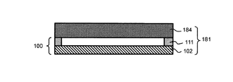
図25は、本発明の一実施形態に係る露光原版181の断面の構成を示す模式図である。一例として、露光原版181は、ペリクル膜102及びペリクル用支持枠111を含むペリクル100と、原版184と、を備える。本発明に係る露光原版181は、原版184に装着された極端紫外光リソグラフィ用のペリクル膜102が設けられたペリクル100において、ペリクル用支持枠111の通気孔に設けられたフィルタ30の着脱を可能にし、原版184へのコンタミネーションを低減することができる。図25においては、ペリクル膜102及びペリクル用支持枠111を含むペリクル100をパターンが形成された原版184の面に配置する例を示したが、本発明に係る露光原版はこれに限定されるものではなく、上述した各実施形態において説明した支持枠を有するペリクルを配置してもよい。
[Exposure original]
FIG. 25 is a schematic view showing the structure of a cross section of the exposure original plate 181 according to the embodiment of the present invention. As an example, the exposure original plate 181 includes a pellicle 100 including a pellicle film 102 and a support frame 111 for a pellicle, and an original plate 184. The exposure original plate 181 according to the present invention allows the filter 30 provided in the ventilation hole of the pellicle support frame 111 to be attached and detached in the pellicle 100 provided with the pellicle film 102 for extreme ultraviolet light lithography mounted on the original plate 184. It is possible to reduce the contamination to the original plate 184. FIG. 25 shows an example in which the pellicle 100 including the pellicle film 102 and the support frame 111 for the pellicle is arranged on the surface of the original plate 184 on which the pattern is formed, but the exposure original plate according to the present invention is limited to this. Instead, a pellicle having the support frame described in each of the above-described embodiments may be arranged.

本発明に係るペリクルを原版に装着する方法は、特に限定されない。例えば、原版に支持枠を直接貼り付けてもよく、支持枠の一方の端面にある原版用接着剤層を介してもよく、機械的に固定する方法や磁石などの引力を利用して原版と支持枠と、を固定してもよい。原版用接着剤層は、接着層39と同様のものを用いることができるため詳細な記載は省略する。 The method of mounting the pellicle according to the present invention on the original plate is not particularly limited. For example, the support frame may be directly attached to the original plate, or may be passed through an adhesive layer for the original plate on one end face of the support frame, and may be mechanically fixed or the original plate may be subjected to an attractive force such as a magnet. The support frame and the support frame may be fixed. Since the same adhesive layer as that of the adhesive layer 39 can be used as the adhesive layer for the original plate, detailed description thereof will be omitted.

[ペリクルの用途]
本発明のペリクルは、EUV露光装置内で、原版に異物が付着することを抑制するための保護部材としてだけでなく、原版の保管時や、原版の運搬時に原版を保護するための保護部材としてもよい。例えば、原版にペリクルを装着した状態(露光原版)にしておけば、EUV露光装置から取り外した後、そのまま保管すること等が可能となる。ペリクルを原版に装着する方法には、接着剤で貼り付ける方法、機械的に固定する方法等がある。
[Use of pellicle]
The pellicle of the present invention is used not only as a protective member for suppressing foreign matter from adhering to the original plate in the EUV exposure apparatus, but also as a protective member for protecting the original plate during storage of the original plate and transportation of the original plate. May be good. For example, if the pellicle is attached to the original plate (exposure original plate), it can be stored as it is after being removed from the EUV exposure apparatus. The method of attaching the pellicle to the original plate includes a method of attaching with an adhesive, a method of mechanically fixing the pellicle, and the like.

[露光装置]
図26は、本発明の一実施形態に係る露光装置180を示す模式図である。図26において、露光原版181は断面図で示す。
[Exposure device]
FIG. 26 is a schematic view showing an exposure apparatus 180 according to an embodiment of the present invention. In FIG. 26, the exposure original plate 181 is shown in a cross-sectional view.

一例として、EUV露光装置180は、EUV光を放出する光源182と、本実施形態の露光原版の一例である露光原版181と、光源182から放出されたEUV光を露光原版181に導く照明光学系183と、を備える。 As an example, the EUV exposure apparatus 180 is an illumination optical system that guides the EUV light emitted from the light source 182, the exposure original plate 181 which is an example of the exposure original plate of the present embodiment, and the EUV light emitted from the light source 182 to the exposure original plate 181. 183 and.

EUV露光装置180では、光源182から放出されたEUV光が照明光学系183で集光され照度が均一化され、露光原版181に照射される。露光原版181に照射されたEUV光は、原版184によりパターン状に反射される。 In the EUV exposure apparatus 180, the EUV light emitted from the light source 182 is collected by the illumination optical system 183, the illuminance is made uniform, and the exposure master plate 181 is irradiated. The EUV light applied to the exposure original plate 181 is reflected in a pattern by the original plate 184.

この露光原版181は、本実施形態の露光原版の一例である。光源182から放出されたEUV光がペリクル膜102を透過して原版184に照射されるように配置されている。原版184は、照射されたEUV光をパターン状に反射するものである。 The exposure original plate 181 is an example of the exposure original plate of the present embodiment. The EUV light emitted from the light source 182 is arranged so as to pass through the pellicle film 102 and irradiate the original plate 184. The original plate 184 reflects the irradiated EUV light in a pattern.

照明光学系183には、EUV光の光路を調整するための複数枚の多層膜ミラー189と光結合器(オプティカルインテグレーター)等が含まれる。 The illumination optical system 183 includes a plurality of multilayer mirrors 189 for adjusting the optical path of EUV light, an optical coupler, and the like.

光源182及び照明光学系183は、公知の光源及び照明光学系を用いることができる。 As the light source 182 and the illumination optical system 183, known light sources and illumination optical systems can be used.

EUV露光装置180において、光源182と照明光学系183との間、及び照明光学系183と原版184の間には、フィルター・ウィンドウ185及び186がそれぞれ設置されている。フィルター・ウィンドウ185及び186は、飛散粒子(デブリ)を捕捉し得るものである。また、EUV露光装置180は、原版184が反射したEUV光を感応基板187へ導く投影光学系188を備えている。投影光学系188は、原版184が反射したEUV光を感応基板187へ導くために、複数の多層ミラー190及び多層膜ミラー191を備えてもよい。
In the EUV exposure apparatus 180, filter windows 185 and 186 are installed between the light source 182 and the illumination optical system 183, and between the illumination optical system 183 and the original plate 184, respectively. The filter windows 185 and 186 are capable of capturing scattered particles (debris). Further, the EUV exposure apparatus 180 includes a projection optical system 188 that guides the EUV light reflected by the original plate 184 to the sensitive substrate 187. The projection optical system 188, to guide the EUV light original 184 is reflected to the photosensitive substrate 187 may comprise a plurality of multilayer mirrors 190 and the multilayer film mirror 191.

本発明の一実施形態に係る露光装置は、通気孔にフィルタが着脱可能に設けられ、極端紫外光リソグラフィ用のペリクル膜が設けられたペリクルが露光原版に接続されているため、露光装置の光学系への影響を低減することができる。 In the exposure apparatus according to the embodiment of the present invention, a filter is provided in a vent hole so as to be removable, and a pellicle provided with a pellicle film for extreme ultraviolet light lithography is connected to an exposure master plate. The influence on the system can be reduced.

本実施形態の露光装置は、露光光(好ましくはEUV光等、より好ましくはEUV光。以下同じ。)を放出する光源と、本実施形態の露光原版と、光源から放出された露光光を露光原版に導く光学系と、を備え、露光原版は、光源から放出された露光光がペリクル膜を透過して原版に照射されるように配置されていることが好ましい。 The exposure apparatus of the present embodiment exposes a light source that emits exposure light (preferably EUV light or the like, more preferably EUV light; the same applies hereinafter), the exposure master plate of the present embodiment, and the exposure light emitted from the light source. It is preferable that the exposure original plate is provided with an optical system leading to the original plate, and the exposure original plate is arranged so that the exposure light emitted from the light source passes through the pellicle film and irradiates the original plate.

この態様によれば、EUV光等によって微細化されたパターン(例えば線幅32nm以下)を形成できることに加え、異物による解像不良が問題となり易いEUV光を用いた場合であっても、異物による解像不良が低減されたパターン露光を行うことができる。 According to this aspect, in addition to being able to form a finely divided pattern (for example, a line width of 32 nm or less) by EUV light or the like, even when EUV light is used, which tends to cause a problem of poor resolution due to foreign matter, it is caused by foreign matter. Pattern exposure with reduced resolution defects can be performed.

[半導体装置の製造方法]
本実施形態の半導体装置の製造方法は、光源から放出された露光光を、本実施形態の露光原版のペリクル膜を透過させて原版に照射し、原版で反射させるステップと、原版によって反射された露光光を、ペリクル膜を透過させて感応基板に照射することにより、感応基板をパターン状に露光するステップと、を有する。
[Manufacturing method of semiconductor devices]
In the method of manufacturing the semiconductor device of the present embodiment, the exposure light emitted from the light source is transmitted through the pellicle film of the exposure original plate of the present embodiment, irradiated to the original plate, and reflected by the original plate, and is reflected by the original plate. It has a step of exposing the sensitive substrate in a pattern by irradiating the sensitive substrate with the exposure light through the pellicle film.

本実施形態の半導体装置の製造方法によれば、異物による解像不良が問題となり易いEUV光を用いた場合であっても、異物による解像不良が低減された半導体装置を製造することができる。例えば本発明に係る露光装置を用いることで、本実施形態の半導体装置の製造方法を行うことができる。 According to the method for manufacturing a semiconductor device of the present embodiment, it is possible to manufacture a semiconductor device in which resolution defects due to foreign substances are reduced even when EUV light is used, in which resolution defects due to foreign substances are likely to be a problem. .. For example, by using the exposure apparatus according to the present invention, the method for manufacturing the semiconductor device of the present embodiment can be performed.

本発明の一実施形態に係る半導体装置の製造方法によると、通気孔にフィルタが着脱可能に設けられ、極端紫外光リソグラフィ用のペリクル膜が設けられたペリクルが露光原版に接続されているため、極端紫外光リソグラフィにおいて、高精細の露光を行うことができる。 According to the method for manufacturing a semiconductor device according to an embodiment of the present invention, a pellicle provided with a removable filter in the ventilation hole and a pellicle film for extreme ultraviolet light lithography is connected to the exposure original plate. In extreme ultraviolet light lithography, high-definition exposure can be performed.

1 通気孔、3 孔、5 孔、7 孔、11 第1の支持枠部、11a 第1の本体部、11A 第1の支持枠部、11B 第1の支持枠部、11C 第1の支持枠部、11E 第1の支持枠部、11G 第1の支持枠部、11b 第1の係合部、11c 第1の延在部、11d 第2の延在部、11e 第1の延在部、11f 第2の延在部、11g 第1の延在部、11h 第2の延在部、12A 薄板、12C−1 薄板、12C−2 薄板、12F 薄板、12G 薄板、12a 凹部(窪み形状)13A 薄板、13C 薄板、13F 薄板、13G 薄板、13a 開口部、14A 薄板、14B 薄板、14C−1 薄板、14C−2 薄板、14C−3 薄板、15 薄板、15B 薄板、15C 薄板、16 第2の支持枠部、16A 第2の支持枠部、16B 第2の支持枠部、16C 第2の支持枠部、16D 第2の支持枠部、16G 第2の支持枠部、16a 第2の本体部、16b 第2の係合部、16c 第1の溝部、16d 第2の溝部、16e 第1の溝部、16f 第2の溝部、16g 第1の溝部、16h 第2の溝部、16l ロック機構、17A 薄板、17B 薄板、17C−1 薄板、17C−2 薄板、17D 薄板、17F 壁、17G 薄板、17a 開口部、17b 開口部、18 薄板、18A 薄板、18B 薄板、18C 薄板、18D 薄板、18G 薄板、18a 凹部(窪み形状)、18b 開口部、19A 薄板、19D 薄板、19G 引掛け部、19G−1 平板状の部材、19G−2 壁状の部材、21D 薄板、23D 固定具、21a 凹部(窪み形状)21b 開口部、24D 第3の係合部、25E 天板、30 フィルタ、30D フィルタ、30G フィルタ、39 接着層、100 ペリクル、102 ペリクル膜、104 第1の枠体、106 ペリクル枠体、111 ペリクル用支持枠、111A ペリクル用支持枠、111B ペリクル用支持枠、111C ペリクル用支持枠、111D ペリクル用支持枠、111E ペリクル用支持枠、180 露光装置、181 露光原版、182 光源、183 照明光学系、184 原版、185 フィルター・ウィンドウ、187 感応基板、188 投影光学系、189 多層膜ミラー、190 多層膜ミラー、191 多層膜ミラー
1 Vent hole, 3 hole, 5 hole, 7 hole, 11 1st support frame part, 11a 1st main body part, 11A 1st support frame part, 11B 1st support frame part, 11C 1st support frame , 11E 1st support frame part, 11G 1st support frame part, 11b 1st engagement part, 11c 1st extension part, 11d 2nd extension part, 11e 1st extension part, 11f 2nd extension, 11g 1st extension, 11h 2nd extension, 12A thin plate, 12C-1 thin plate, 12C-2 thin plate, 12F thin plate, 12G thin plate, 12a recess (recess shape) , 13A thin, 13C sheet, 13F sheet, 13G thin, 13a opening, 14A thin, 14B thin, 14C-1 sheet, 14C-2 sheet, 14C-3 sheet, 15 A thin, 15B thin, 15C sheet, 16 second Support frame part, 16A second support frame part, 16B second support frame part, 16C second support frame part, 16D second support frame part, 16G second support frame part, 16a second main body 16b second engaging part, 16c first groove part, 16d second groove part, 16e first groove part, 16f second groove part, 16g first groove part, 16h second groove part, 16l locking mechanism, 17A thin plate, 17B thin plate, 17C-1 thin plate, 17C-2 thin plate, 17D thin plate, 17F wall, 17G thin plate, 17a opening, 17b opening, 18 thin plate, 18A thin plate, 18B thin plate, 18C thin plate, 18D thin plate, 18G thin plate , 18a recess (recess shape), 18b opening, 19A thin plate, 19D thin plate, 19G hook part, 19G-1 flat plate member, 19G-2 wall member, 21D thin plate, 23D fixture, 21a recess (recess) Shape) , 21b opening, 24D third engaging part, 25E top plate, 30 filter, 30D filter, 30G filter, 39 adhesive layer, 100 pellicle, 102 pellicle film, 104 first frame, 106 pellicle frame , 111 pellicle support frame, 111A pellicle support frame, 111B pellicle support frame, 111C pellicle support frame, 111D pellicle support frame, 111E pellicle support frame, 180 exposure device, 181 exposure original plate, 182 light source, 183 lighting Optical system, 184 original plate, 185 filter window, 187 sensitive substrate, 188 projection optical system, 189 multilayer mirror, 190 multilayer mirror, 191 multilayer mirror

Claims (17)

第1の支持枠部と、第2の支持枠部と、フィルタと、を有するペリクル用支持枠であって、
前記フィルタは平板状の枠形状を有し、前記第1の支持枠部と前記第2の支持枠部とに挟持され、
前記第1の支持枠部は、平板状の枠形状を有する第1の本体部と、前記第1の本体部から前記ペリクル用支持枠の厚み方向に突出した第1の係合部と、を有し、
前記第2の支持枠部は、平板状の枠形状を有する第2の本体部と、前記第2の本体部の前記ペリクル用支持枠の厚み方向に設けられた凹部に配置され、前記第1の係合部と係合する第2の係合部と、を有することを特徴とするペリクル用支持枠。
A support frame for a pellicle having a first support frame portion, a second support frame portion, and a filter.
The filter has a flat plate-like frame shape, and is sandwiched between the first support frame portion and the second support frame portion.
The first support frame portion includes a first main body portion having a flat plate-like frame shape, and a first engaging portion protruding from the first main body portion in the thickness direction of the pellicle support frame. Have and
The second support frame portion is arranged in a second main body portion having a flat plate-like frame shape and a recess provided in the second main body portion in the thickness direction of the pellicle support frame, and the first support frame portion. A support frame for a pellicle, which comprises a second engaging portion that engages with the engaging portion of the pellicle.
前記第1の係合部は、前記第1の本体部から前記ペリクル用支持枠の厚み方向に延在する第1の延在部と、前記第1の延在部の前記第1の本体部とは反対側の端部から前記ペリクル用支持枠の厚み方向と交差する方向に延在する第2の延在部と、を有し、
前記第2の係合部は、前記第1の支持枠部側に位置する前記第2の支持枠部の第1の面から前記ペリクル用支持枠の厚み方向に延在する第1の溝部と、前記第1の溝部の底部から前記ペリクル用支持枠の厚み方向と交差する方向に延在する第2の溝部とを有し、
前記第2の延在部の少なくとも一部は、前記第2の溝部に収容されることを特徴とする請求項1に記載のペリクル用支持枠。
The first engaging portion includes a first extending portion extending from the first main body portion in the thickness direction of the pellicle support frame, and the first main body portion of the first extending portion. It has a second extending portion extending in a direction intersecting the thickness direction of the pellicle support frame from the end portion on the opposite side to the above.
The second engaging portion includes a first groove portion extending in the thickness direction of the pellicle support frame from the first surface of the second support frame portion located on the side of the first support frame portion. A second groove extending from the bottom of the first groove in a direction intersecting the thickness direction of the pellicle support frame.
The support frame for a pellicle according to claim 1, wherein at least a part of the second extending portion is housed in the second groove portion.
前記フィルタは、前記第1の係合部及び前記第2の係合部に対応する位置に開口を有し、
前記第1の係合部は、前記開口を貫通して、前記第2の係合部と係合することを特徴とする請求項1に記載のペリクル用支持枠。
The filter has openings at positions corresponding to the first engaging portion and the second engaging portion.
The support frame for a pellicle according to claim 1, wherein the first engaging portion penetrates the opening and engages with the second engaging portion.
前記第2の係合部は、前記第2の溝部の底部から前記第1の面の方向に離間して配置される固定具を有し、
前記第2の溝部は、前記第1の溝部の底部と前記固定具とにより構成されることを特徴とする請求項2に記載のペリクル用支持枠。
The second engaging portion has a fixture that is disposed apart from the bottom of the second groove in the direction of the first surface.
The support frame for a pellicle according to claim 2, wherein the second groove portion is composed of a bottom portion of the first groove portion and the fixture.
前記固定具は、治具と係合可能な第3の係合部を有することを特徴とする請求項4に記載のペリクル用支持枠。 The support frame for a pellicle according to claim 4, wherein the fixture has a third engaging portion that can be engaged with a jig. 前記ペリクル用支持枠の内縁部と外縁部とを接続し、前記フィルタが配置された通気孔をさらに有することを特徴とする請求項1に記載のペリクル用支持枠。 The support frame for a pellicle according to claim 1, wherein the inner edge portion and the outer edge portion of the support frame for the pellicle are connected to each other, and the support frame for the pellicle further has a ventilation hole in which the filter is arranged. 前記通気孔は、前記フィルタが配置され、前記ペリクル用支持枠の厚み方向と略平行な第1の方向に延びる第1の孔と、
前記第1の孔の第1の端部に接続し、前記第1の方向と交差する第2の方向に延伸し、前記内縁部又は前記外縁部に開口を有する第2の孔と、
を有することを特徴とする請求項6に記載のペリクル用支持枠。
The ventilation holes include a first hole in which the filter is arranged and extending in a first direction substantially parallel to the thickness direction of the pellicle support frame.
A second hole that connects to the first end of the first hole, extends in a second direction that intersects the first direction, and has an opening at the inner or outer edge.
The support frame for a pellicle according to claim 6, wherein the support frame for a pellicle is provided.
前記通気孔は、前記第1の孔の第2の端部に接続し、前記ペリクル用支持枠の厚み方向と交差する方向に設けられた第3の孔をさらに有することを特徴とする請求項7に記載のペリクル用支持枠。 The claim is characterized in that the ventilation hole is connected to a second end portion of the first hole and further has a third hole provided in a direction intersecting the thickness direction of the pellicle support frame. The support frame for the pellicle according to 7. 複数の前記第1の係合部と、複数の前記第2の係合部と、複数の前記通気孔と、を備えることを特徴とする請求項8に記載のペリクル用支持枠。 The support frame for a pellicle according to claim 8, further comprising a plurality of the first engaging portions, a plurality of the second engaging portions, and the plurality of the vent holes. 前記第1の支持枠部は、前記第1の本体部を構成する枠形状を有する薄板と、前記第1の延在部を構成する薄板と、前記第2の延在部を構成する薄板と、を含む積層体であることを特徴とする請求項2に記載のペリクル用支持枠。 The first support frame portion includes a thin plate having a frame shape constituting the first main body portion, a thin plate constituting the first extending portion, and a thin plate forming the second extending portion. The support frame for a pellicle according to claim 2, wherein the support frame includes, and is a laminated body. 前記第2の支持枠部は、前記第1の溝部を構成する薄板と、前記第2の溝部を構成する薄板と、を含む積層体であることを特徴とする請求項2に記載のペリクル用支持枠。 The pellicle for a pellicle according to claim 2, wherein the second support frame portion is a laminated body including a thin plate forming the first groove portion and a thin plate forming the second groove portion. Support frame. 前記フィルタの前記枠形状の内側に配置された壁をさらに有することを特徴とする請求項1に記載のペリクル用支持枠。 The support frame for a pellicle according to claim 1, further comprising a wall arranged inside the frame shape of the filter. 請求項1乃至12の何れか一に記載のペリクル用支持枠と、ペリクル膜とを有することを特徴とするペリクル。 A pellicle having the pellicle support frame according to any one of claims 1 to 12 and a pellicle film. 請求項13に記載のペリクルと、原版と、を有することを特徴とする露光原版。 An exposure original plate comprising the pellicle according to claim 13 and an original plate. 請求項14に記載の露光原版と、光学系とを有することを特徴とする露光装置。 An exposure apparatus comprising the exposure original plate according to claim 14 and an optical system. 平板状の枠形状を有する第1の本体部と、前記第1の本体部からペリクル用支持枠の厚み方向に突出した第1の係合部と、を有する第1の支持枠部を準備し、
平板状の枠形状を有する第2の本体部と、前記第2の本体部の前記ペリクル用支持枠の厚み方向に設けられた凹部に配置され、前記第1の係合部と係合する第2の係合部と、を有する第2の支持枠部を準備し、
平板状の枠形状を有するフィルタを準備し、
前記フィルタを前記第1の支持枠部と前記第2の支持枠部とを挟持し、前記第1の係合部と前記第2の係合部とを係合することを特徴とするペリクル用支持枠の製造方法。
A first support frame portion having a first main body portion having a flat plate-shaped frame shape and a first engaging portion protruding from the first main body portion in the thickness direction of the pellicle support frame is prepared. ,
A second main body having a flat plate-like frame shape and a recess provided in the second main body in the thickness direction of the pellicle support frame to engage with the first engaging portion. Prepare a second support frame portion having 2 engaging portions and
Prepare a filter with a flat frame shape,
For a pellicle, the filter is sandwiched between the first support frame portion and the second support frame portion, and the first engaging portion and the second engaging portion are engaged with each other. Manufacturing method of support frame.
前記第1の本体部を構成する薄板と、第1の延在部を構成する薄板と、第2の延在部を構成する薄板とを接続して、前記第1の本体部から前記ペリクル用支持枠の厚み方向に突出した第1の係合部を有する前記第1の支持枠部を準備し、
第1の溝部を構成する薄板と、第2の溝部を構成する薄板と、前記第2の本体部を構成する薄板とを接続して、前記第2の係合部を有する前記第2の支持枠部を準備し、
前記第2の延在部の少なくとも一部を前記第2の溝部に収容して、前記第1の係合部と前記第2の係合部とを係合することを特徴とする請求項16に記載のペリクル用支持枠の製造方法。
The thin plate forming the first main body portion, the thin plate forming the first extending portion, and the thin plate forming the second extending portion are connected, and the pellicle is used from the first main body portion. The first support frame portion having the first engaging portion protruding in the thickness direction of the support frame is prepared.
The second support having the second engaging portion by connecting the thin plate forming the first groove portion, the thin plate forming the second groove portion, and the thin plate forming the second main body portion. Prepare the frame and
16. A claim 16 characterized in that at least a part of the second extending portion is housed in the second groove portion to engage the first engaging portion with the second engaging portion. A method for manufacturing a support frame for a pellicle according to the above.
JP2020525616A 2018-06-12 2019-06-12 A support frame for a pellicle, a method for manufacturing a pellicle and a support frame for a pellicle, and an exposure plate and an exposure apparatus using the pellicle. Active JP6941733B2 (en)

Applications Claiming Priority (3)

Application Number Priority Date Filing Date Title
JP2018111648 2018-06-12
PCT/JP2019/023267 WO2019240166A1 (en) 2018-06-12 2019-06-12 Pellicle support frame, pellicle, method for manufacturing pellicle support frame, and exposure original plate and exposure device employing pellicle

Publications (2)

Publication Number Publication Date
JPWO2019240166A1 JPWO2019240166A1 (en) 2021-05-20
JP6941733B2 true JP6941733B2 (en) 2021-09-29

Family

ID=68842924

Family Applications (1)

Application Number Title Priority Date Filing Date
JP2020525616A Active JP6941733B2 (en) 2018-06-12 2019-06-12 A support frame for a pellicle, a method for manufacturing a pellicle and a support frame for a pellicle, and an exposure plate and an exposure apparatus using the pellicle.

Country Status (7)

Country Link
US (1) US11204547B2 (en)
EP (1) EP3809202A4 (en)
JP (1) JP6941733B2 (en)
KR (1) KR102459119B1 (en)
CN (1) CN112154376B (en)
TW (1) TWI787522B (en)
WO (1) WO2019240166A1 (en)

Families Citing this family (9)

* Cited by examiner, † Cited by third party
Publication number Priority date Publication date Assignee Title
CN111919171A (en) * 2018-03-27 2020-11-10 三井化学株式会社 Supporting frame for protection piece, protection piece and manufacturing method thereof, and exposure master and semiconductor device manufacturing method using the same
US11137693B2 (en) * 2018-11-30 2021-10-05 Iucf-Hyu (Industry-University Cooperation Foundation Hanyang University) Pellicle holder, pellicle inspection apparatus, and pellicle inspection method
TWI796629B (en) * 2020-01-31 2023-03-21 台灣積體電路製造股份有限公司 Lithography system, reticle structure and manufacturing method of reticle structure
US11662661B2 (en) 2020-01-31 2023-05-30 Taiwan Semiconductor Manufacturing Co., Ltd. EUV pellicle with structured ventilation frame
EP4165469A4 (en) 2020-09-16 2023-12-13 Lintec Of America, Inc. Ultra-thin, ultra-low density films for euv lithography
CN112684672B (en) * 2020-12-30 2022-07-01 南京深光科技有限公司 Mask metal frame conveying module
JP2022191120A (en) * 2021-06-15 2022-12-27 信越化学工業株式会社 Pellicle for exposure with easy air pressure adjustment
TW202326288A (en) * 2021-08-25 2023-07-01 日商信越化學工業股份有限公司 Exposure pellicle capable of adjusting atmospheric pressure at high speed
WO2023041185A1 (en) * 2021-09-20 2023-03-23 Applied Materials, Inc. Mask frame support element, edge exclusion mask, mask frame element, substrate support, substrate processing apparatus, and method of manufacturing one or more devices on a substrate

Family Cites Families (21)

* Cited by examiner, † Cited by third party
Publication number Priority date Publication date Assignee Title
JPH1062966A (en) * 1996-08-13 1998-03-06 Shin Etsu Chem Co Ltd Pellicle for lithography
JPH11295880A (en) * 1998-04-07 1999-10-29 Seiko Epson Corp Pellicle frame
JP2002107915A (en) * 2000-10-02 2002-04-10 Asahi Glass Co Ltd Pellicle and method for fixing pellicle plate and pellicle frame each other
JP2005268464A (en) * 2004-03-18 2005-09-29 Canon Inc Reticle cover and exposure apparatus
JP4577069B2 (en) * 2005-03-31 2010-11-10 日本軽金属株式会社 Pellicle support frame, pellicle frame, and method for manufacturing pellicle frame
JP4637053B2 (en) * 2006-05-15 2011-02-23 信越化学工業株式会社 Pellicle and pellicle peeling device
WO2008105531A1 (en) * 2007-03-01 2008-09-04 Nikon Corporation Pellicle frame apparatus, mask, exposure method, exposure apparatus and device manufacturing method
JP5731147B2 (en) * 2010-09-01 2015-06-10 旭化成イーマテリアルズ株式会社 Pellicle frame and pellicle
TWM401792U (en) * 2010-09-20 2011-04-11 He zhong-shan Frame device of photo-mask protection film
US8586267B2 (en) * 2011-09-12 2013-11-19 Samsung Austin Semiconductor, L.P. Removable transparent membrane for a pellicle
JP2013222143A (en) * 2012-04-18 2013-10-28 Renesas Electronics Corp Semiconductor device manufacturing method and exposure mask
US8968971B2 (en) * 2013-03-08 2015-03-03 Micro Lithography, Inc. Pellicles with reduced particulates
CN103246157A (en) * 2013-05-21 2013-08-14 上海和辉光电有限公司 Dustproof film framework, optical mask and installation method thereof
KR101918687B1 (en) * 2014-01-28 2018-11-14 삼성전자주식회사 Pellicle
EP3196699A4 (en) * 2014-09-19 2018-05-16 Mitsui Chemicals, Inc. Pellicle, production method thereof, exposure method
EP3196700B1 (en) * 2014-09-19 2019-01-30 Mitsui Chemicals, Inc. Pellicle, pellicle production method and exposure method using pellicle
JP6395320B2 (en) * 2015-03-30 2018-09-26 信越化学工業株式会社 Pellicle
CN107533283B (en) * 2015-04-27 2021-05-28 三井化学株式会社 Method for manufacturing pellicle and method for manufacturing photomask with pellicle
JP2017083791A (en) * 2015-10-30 2017-05-18 三井化学株式会社 Pellicle, method for producing pellicle and exposure method using the pellicle
JP6478283B2 (en) 2015-12-24 2019-03-06 信越化学工業株式会社 EUV exposure pellicle
JP6781864B2 (en) * 2016-07-05 2020-11-11 三井化学株式会社 Pellicle film, pellicle frame, pellicle, manufacturing method thereof, exposure original plate, exposure device, manufacturing method of semiconductor device

Also Published As

Publication number Publication date
WO2019240166A1 (en) 2019-12-19
EP3809202A1 (en) 2021-04-21
CN112154376A (en) 2020-12-29
TW202001414A (en) 2020-01-01
US20210080824A1 (en) 2021-03-18
EP3809202A4 (en) 2022-03-16
TWI787522B (en) 2022-12-21
JPWO2019240166A1 (en) 2021-05-20
US11204547B2 (en) 2021-12-21
CN112154376B (en) 2023-08-18
KR102459119B1 (en) 2022-10-26
KR20200138384A (en) 2020-12-09

Similar Documents

Publication Publication Date Title
JP6941733B2 (en) A support frame for a pellicle, a method for manufacturing a pellicle and a support frame for a pellicle, and an exposure plate and an exposure apparatus using the pellicle.
TWI741498B (en) Mask assembly container, pellicle assembly container, pellicle assembly, and method for making said pellicle assembly
KR102634793B1 (en) Mask assembly
CN113917783B (en) Protective film assembly, method for manufacturing the same, and exposure method
TWI670561B (en) Pellicle frame, pellicle and process for producing the same, exposure original plate and process for producing the same, exposure apparatus, and process for producing semiconductor device
KR101910302B1 (en) Pellicle, pellicle production method and exposure method using pellicle
JP2017083791A (en) Pellicle, method for producing pellicle and exposure method using the pellicle
KR20040064225A (en) Removable reticle window and support frame using magnetic force
WO2015174412A1 (en) Pellicle frame, pellicle, frame member, exposure original plate, exposure device, and method for manufacturing semiconductor device
TW201600924A (en) Pellicle mount apparatus
JP6945726B2 (en) Support frame for pellicle, pellicle, and manufacturing method thereof, and exposure original plate and semiconductor device manufacturing method using these.
JP2007141925A (en) Mask storage container and aligner
KR20040098753A (en) Reticle

Legal Events

Date Code Title Description
A521 Request for written amendment filed

Free format text: JAPANESE INTERMEDIATE CODE: A523

Effective date: 20201106

A621 Written request for application examination

Free format text: JAPANESE INTERMEDIATE CODE: A621

Effective date: 20201106

TRDD Decision of grant or rejection written
A01 Written decision to grant a patent or to grant a registration (utility model)

Free format text: JAPANESE INTERMEDIATE CODE: A01

Effective date: 20210817

A61 First payment of annual fees (during grant procedure)

Free format text: JAPANESE INTERMEDIATE CODE: A61

Effective date: 20210906

R150 Certificate of patent or registration of utility model

Ref document number: 6941733

Country of ref document: JP

Free format text: JAPANESE INTERMEDIATE CODE: R150